Printable Version of Topic
Click here to view this topic in its original format
914World.com _ 914World Garage _ Assistance with Restoring 73 Wiring Harness
Posted by: doug_b_928 Jan 31 2018, 03:55 PM
My main Winter project is to 'restore' the wiring harness on my 73. I admit that of all the jobs involved in restoring this car, this is the one that creates the most anxiety in me. I took it out of it's container last winter, spread it out on the floor, and promptly proceeded to put it back in the container. But, the time has come to conquer this thing. I have 4 rolls of wire tape that cost more to ship to me than the tape itself, and I think everything I need to do the job. I have pieces of a 74 harness (which I'm aware is not the same) and have already used one of the correct connectors from it for one of the license plate light connectors. Overall, I think the harness could be a lot worse, but there are some areas where POs have made some modifications/fixes and I'm not sure what they've done and why. I'll be asking for assistance from the wiring gurus in the thread as I work my way through. I have the wiring diagram from Jeff Bowlsby's website, a multimeter, PowerProbe3, and cleaning supplies. I'm removing all the tape, inspecting, cleaning, and then installing new tape. I'm just going to clean and inspect the rubber covered sheaths as they seem to be tight around the wires and it seems unlikely that there is anything wrong underneath them (on the upside, everything that ever worked on the car during my ownership, which wasn't everything that was supposed to, still did right before I removed the harness).
Okay, so with that introduction, my first questions. Starting at the back, I've worked my way through the license plate wires, to the trunk light wires, and I'm currently looking at the fuel pump wires. My car had vapor lock, so the fuel pump was relocated to the front of the car. The mechanic just cut the wires, left the ground wire dangling, and spliced in a positive wire which he ran through the firewall (poking a hole; no grommet), under the carpet and through a hole in the front firewall, where he then spliced in the connector and grounded to a screw he added to the front firewall. Here's a pic of the wires: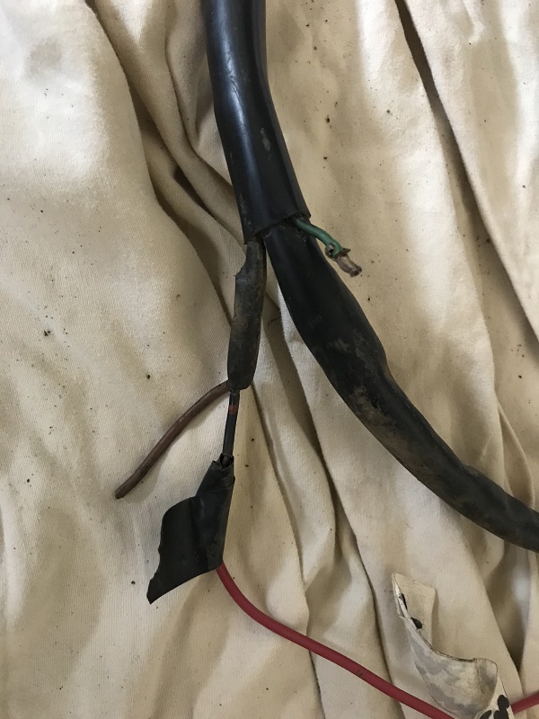
Because of the vapor lock issue, I'm thinking I should put my new pump in the front where the old one was (by the steering rack). I'm thinking of getting the NAPA Bosch fuel pump (N69133). From what I can tell looking at the wiring diagram, and I could be reading it wrong, the power wire goes to the 'regulator/relay plate). If it's source was at the fuse box under the dash I'd splice into the wire up there and put the original connector back on the wires in the engine bay (in case I ever wanted to put an original style in its original spot. If I'm correct about the wiring diagram, then, with my limited knowledge, I guess I have to run the power wire on the outside of the sheath (but at least it will be inside the new 914 rubber snorkel) and up to the fuel pump in the front? Is there any point in running the ground wire that way too, or would you just ground it to a screw on the car as it was before?
Also, in the pic above there is a green wire that looks like it had a connector on it at one time. Does anyone know what that was for? When I look at the 73 diagram it only shows the black with red dots and the ground for the fuel pump. On the diagram it shows the, IIRC, 'fan blower motor' having a green wire. However, if that's referring to the blower motor for the heater, I think the wires and connector below were for that (note no green wire).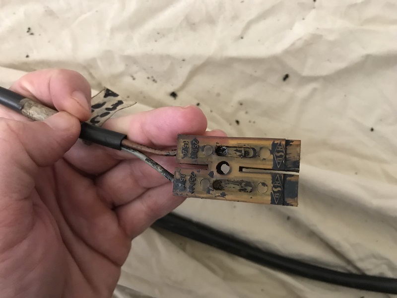
So, to summarize, what's the best approach for the fuel pump wiring, and what is that green wire for?
Posted by: dr914@autoatlanta.com Jan 31 2018, 05:11 PM
cannot tell much from the pics but if it is a green wire with a black stripe and it is near the original fuel pump lead wires, it is for the optional oil temperature sensor. Original had a plastic housing around it and connected to another wire that was sheathed and led down to the bottom of the sump

My main Winter project is to 'restore' the wiring harness on my 73. I admit that of all the jobs involved in restoring this car, this is the one that creates the most anxiety in me. I took it out of it's container last winter, spread it out on the floor, and promptly proceeded to put it back in the container. But, the time has come to conquer this thing. I have 4 rolls of wire tape that cost more to ship to me than the tape itself, and I think everything I need to do the job. I have pieces of a 74 harness (which I'm aware is not the same) and have already used one of the correct connectors from it for one of the license plate light connectors. Overall, I think the harness could be a lot worse, but there are some areas where POs have made some modifications/fixes and I'm not sure what they've done and why. I'll be asking for assistance from the wiring gurus in the thread as I work my way through. I have the wiring diagram from Jeff Bowlsby's website, a multimeter, PowerProbe3, and cleaning supplies. I'm removing all the tape, inspecting, cleaning, and then installing new tape. I'm just going to clean and inspect the rubber covered sheaths as they seem to be tight around the wires and it seems unlikely that there is anything wrong underneath them (on the upside, everything that ever worked on the car during my ownership, which wasn't everything that was supposed to, still did right before I removed the harness).
Okay, so with that introduction, my first questions. Starting at the back, I've worked my way through the license plate wires, to the trunk light wires, and I'm currently looking at the fuel pump wires. My car had vapor lock, so the fuel pump was relocated to the front of the car. The mechanic just cut the wires, left the ground wire dangling, and spliced in a positive wire which he ran through the firewall (poking a hole; no grommet), under the carpet and through a hole in the front firewall, where he then spliced in the connector and grounded to a screw he added to the front firewall. Here's a pic of the wires:
Because of the vapor lock issue, I'm thinking I should put my new pump in the front where the old one was (by the steering rack). I'm thinking of getting the NAPA Bosch fuel pump (N69133). From what I can tell looking at the wiring diagram, and I could be reading it wrong, the power wire goes to the 'regulator/relay plate). If it's source was at the fuse box under the dash I'd splice into the wire up there and put the original connector back on the wires in the engine bay (in case I ever wanted to put an original style in its original spot. If I'm correct about the wiring diagram, then, with my limited knowledge, I guess I have to run the power wire on the outside of the sheath (but at least it will be inside the new 914 rubber snorkel) and up to the fuel pump in the front? Is there any point in running the ground wire that way too, or would you just ground it to a screw on the car as it was before?
Also, in the pic above there is a green wire that looks like it had a connector on it at one time. Does anyone know what that was for? When I look at the 73 diagram it only shows the black with red dots and the ground for the fuel pump. On the diagram it shows the, IIRC, 'fan blower motor' having a green wire. However, if that's referring to the blower motor for the heater, I think the wires and connector below were for that (note no green wire).
So, to summarize, what's the best approach for the fuel pump wiring, and what is that green wire for?
Posted by: simonjb Jan 31 2018, 05:45 PM
As an aside, you can buy those connectors from Bughaus
Posted by: bbrock Jan 31 2018, 05:55 PM
cannot tell much from the pics but if it is a green wire with a black stripe and it is near the original fuel pump lead wires, it is for the optional oil temperature sensor. Original had a plastic housing around it and connected to another wire that was sheathed and led down to the bottom of the sump
 I'm just a couple months ahead of you on restoring my '73 harness but mine needed a lot more work. I just need some sleeving and grommets before I can button it up with new terminals where needed.
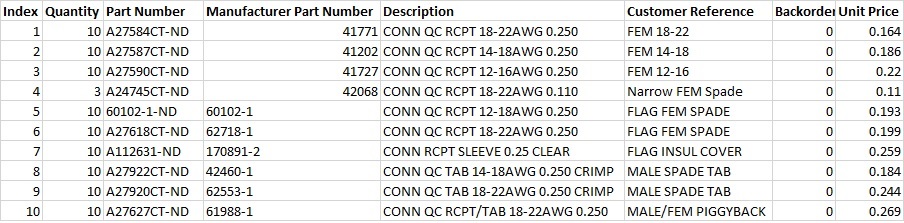
For the fuel pump, mine had already been relocated to the steering rack area but it was a piss poor job and I'm going to move it up into the fuel tank compartment and add a late access cover. To do this, I bought a few meters of black/red 1.0mm txl wire off ebay (18 gauge is about the same gauge and gxl wire is a closer match to OEM) and ran it from the 14-pin connector through the sleeving up to the front trunk where the pump will go. I have a lot of sleeving missing, so it was easier than yours will be, but it can be done. Find a small stiff wire, make sure the end is blunt so it doesn't tear up any insulation, lube it with some glycerine or electricians lube, and fish it up through the sleeve. Then pull you new wire down through the sleeving. For the ground, I ran a brown wire salvaged from another harness from the new pump location up to the blower assembly under the cowl. When everything is buttoned up, I will add one of these: https://www.digikey.com/product-detail/en/te-connectivity-amp-connectors/61988-1/A27627CT-ND/456719. You can't see it in that stupid picture, but it is a dual gender terminal with a male spade coming off the back. The plan is to plug this into the ground terminal at the blower, and plug the blower ground wire into the male spade. You could run your ground to anywhere you like, but this made for a pretty short wire run without having to splice into the harness. This way, the factory schematic will still be correct for my pump even though it is at the other end of the car.
If you need other spade terminals, you can get the OEM AMP terminals dirt cheap from digikey. I made the mistake of buying a bunch of no-name terminals on ebay before buying the good stuff from digikey.
Posted by: earossi Jan 31 2018, 06:15 PM
There is a guy over on the Pelican Engine Rebuilding forum who has a cottage business going to fabricate new Porsche wiring harnesses. He's done tons of these and feedback on the forum is extremely good. Not very expensive either.
Posted by: Jeff Bowlsby Jan 31 2018, 06:20 PM
When relocating the FP to the front note that the factory wiring gage changed significantly. Where the original location below the battery was 16 gage, use 12 gage if it goes to the front, per the factory schematics for 1975-76. For both power and ground circuits.
Posted by: mepstein Jan 31 2018, 06:21 PM
There is a guy over on the Pelican Engine Rebuilding forum who has a cottage business going to fabricate new Porsche wiring harnesses. He's done tons of these and feedback on the forum is extremely good. Not very expensive either.
What’s his name?
Posted by: malcolm2 Jan 31 2018, 06:27 PM
Hope I am not too late. But I bought one of these wire diagrams for my 75. This one should be for you. Double check, cause he has FI, etc....
https://colorwiringdiagrams.com/products/porsche-914-1972-1973
Prospero's Garage
Posted by: doug_b_928 Jan 31 2018, 06:49 PM
Wow! Thank you to all of you for your helpful responses. The expertise on this forum just might get me through this 
Thanks George and Brent for identifying that green wire. So, based on what George said I should put a new spade connector with plastic housing on that and call it good.
I have a pinning tool for removing connectors, but it's too short for these plastic housings. Will have to find something longer.
Brent, I think I'll have to study your posting for 2 weeks before I understand it . It's great to know you've been through this. I can tell you are much more knowledgeable than me so you might have to dumb down your advice to beginner level so that it doesn't go over my head.
Great to know about the housings and connectors and Jeff's tip on wire gauge is awesome (I'd have tried to match it to what's there).
Thanks again guys! Unfortunately, there will be more questions coming but I'm feeling better about it already.
Posted by: gothspeed Jan 31 2018, 06:59 PM
I am just about completed bringing my 73' harness up to snuff. There are tons of useful wire diagrams, sketches and pinout descriptions on Bowlsby's site (link below). I printed and referenced a great many of these. I am so grateful that Mr. Bowlsby keeps this information available to us! And if you need harnesses or sections thereof, he makes those too! 
http://bowlsby.net/914/Classic/TechNotebook.htm
Posted by: bbrock Jan 31 2018, 06:59 PM
Brent, I think I'll have to study your posting for 2 weeks before I understand it
. It's great to know you've been through this. I can tell you are much more knowledgeable than me so you might have to dumb down your advice to beginner level so that it doesn't go over my head.I'll be revisiting mine based on Jeff's wire gauge comment. I used the '74 diagram to decide wire sizes. Whoops!. I didn't really like the look of the thin-wall wire anyway, but will probably use it again with heavier gauge.
So, GXL and TXL. I didn't know about these until I researched for my harness. These are the two wire types that are automotive grade and what you want to look for if you buy wire. TXL is more modern with thin-walled insulation. Easier to pull through sheathing but looks skinney compared to to the same gage wire in the harness. GXL has thicker insulation like the old factory wire.
BTW, I had the same reaction as you looking at the harness at first. But after you spend a little time with it and your dagrams, it starts looking pretty simple.
Posted by: earossi Jan 31 2018, 08:23 PM
There is a guy over on the Pelican Engine Rebuilding forum who has a cottage business going to fabricate new Porsche wiring harnesses. He's done tons of these and feedback on the forum is extremely good. Not very expensive either.
What’s his name?
His forum name on the Pelican Engine Rebuilding forum is "timmy2". His name is Dennis. You should be able to get to him via PM or email.
He has created replacement harnesses for a number of Porsche models. If he does not have the pattern, you just need to send him your old harness and he'll provide a proper replacement with the correct connectors. And, he is reasonable.
Posted by: mepstein Jan 31 2018, 08:49 PM
There is a guy over on the Pelican Engine Rebuilding forum who has a cottage business going to fabricate new Porsche wiring harnesses. He's done tons of these and feedback on the forum is extremely good. Not very expensive either.
What’s his name?
His forum name on the Pelican Engine Rebuilding forum is "timmy2". His name is Dennis. You should be able to get to him via PM or email.
He has created replacement harnesses for a number of Porsche models. If he does not have the pattern, you just need to send him your old harness and he'll provide a proper replacement with the correct connectors. And, he is reasonable.
I know he does engine harnesses for 6’s. I didn’t realize he did chassis wire harness.
Posted by: doug_b_928 Feb 3 2018, 12:47 PM
So, using my spare harness pieces, I found the matching wire and what I think would be the proper housing for the oil temp sensor and installed it (can be seen in the pic below, barely, sorry). I've also put together a plan for the fuel pump wiring. As you can see, I salvaged one of those double housings and the proper connectors. In the pic below everything is just mocked up. I'll solder the wires with the male spade connectors, then install the housing and use female spade connectors with double wires. The double is so I can bring the original fuel pump connector back from the farm and install it on one pair (in case I ever want to install a pump in the original location) and then the other pair will have 12G wires attached that will be run up to the front of the car. I'm doubtful about getting the pair of wires in the small sheath for these wires, but I think I can get them through the shorter piece of sheath that goes up the firewall and has the snorkel around it. Would the edges on a coat hanger be too sharp to push through the sheath for pulling the wires? Anyone see any problems with this plan? 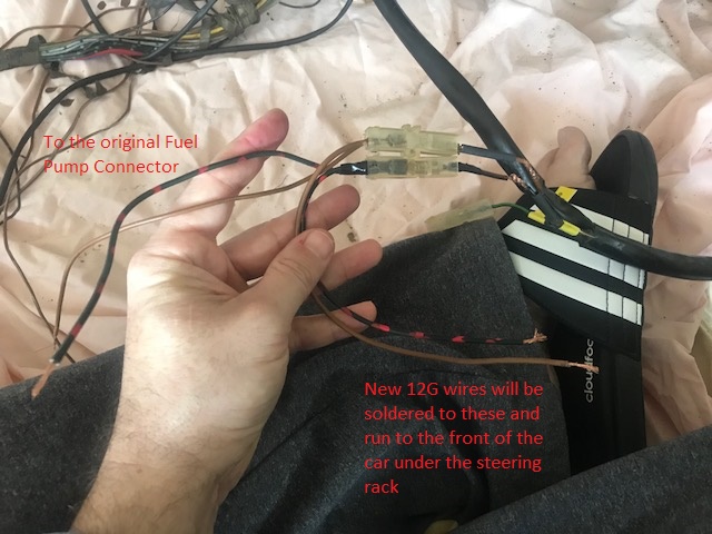
Posted by: Dave_Darling Feb 3 2018, 01:29 PM
A coat-hanger will poke through the snorkel. If you round the end carefully, it might not--not sure. The snorkel on my car has a couple of holes in it...
I wouldn't bother running the ground myself. A ground is a ground, so just running a wire to some fastener going solidly into the chassis should be fine. Or adding one of those Y connector things to an existing grounding lug.
--DD
Posted by: bbrock Feb 3 2018, 02:27 PM
A coat-hanger will poke through the snorkel. If you round the end carefully, it might not--not sure. The snorkel on my car has a couple of holes in it...
I wouldn't bother running the ground myself. A ground is a ground, so just running a wire to some fastener going solidly into the chassis should be fine. Or adding one of those Y connector things to an existing grounding lug.
--DD
Just route a brown wire from the new pump location whatever ground is easy and pleases you. Shorter is better anyway. On my car, there was a length of sheathing in the front trunk that was split and wrapped with ~1/2" wide vinyl electrical tape. I you want to run your wire through there and have trouble, you can just remove the tape, run the wire, then rewrap it and you'll never be able to tell you were in there. I bought some narrow tape on ebay, but I doubt you'd ever notice if you just used regular stuff.
Posted by: Jeff Bowlsby Feb 3 2018, 02:47 PM
Umm...
The 1975-76 schematic indicates that the FP CIRCUIT runs from the 14 pin connector (pin 13) to the fuel pump and needs to be 12 gage, presumably due to the ampacity requirements for that condition. You are leaving half of that circuit as 16 gage, splicing on a 12 gage section. Seems to me that the 16 gage section will be subject to overload and is a fire hazard if it overheats.
Now I know we are going to hear the masses chime in and say they just ran 16 ga lamp cord to the front trunk with no problems. What would an EE's say if (s)he were to anlayze/engineer the loads/distance of that circuit?
Posted by: doug_b_928 Feb 3 2018, 03:17 PM
Hmmm...So you're suggesting to pull the FP wire out of the 14 pin connector and add a 12G in it's place. Are those ends that fit in the 14 pin connector still available? I have a spare 14 pin connector with wires in it, is it possible to pull one of those ends off of a wire and crimp it onto my new wire?
Per Dave and Brent, I'll forego the ground and either connect directly to the chassis or find an existing ground close by.
Posted by: bbrock Feb 3 2018, 03:22 PM
Hmmm...So you're suggesting to pull the FP wire out of the 14 pin connector and add a 12G in it's place. Are those ends that fit in the 14 pin connector still available? I have a spare 14 pin connector with wires in it, is it possible to pull one of those ends off of a wire and crimp it onto my new wire?
You can reuse those pins. They are just soldered on. I unsoldered all of mine off the 14-pin connector just to make it easier to insall new sheathing. Just secure the pin somehow (I used a "helping hands" soldering station) and tug gently on the wire as you heat the pin with the soldering iron. When the solder melts, the wire will pop right out. Jut reverse to reinstall.
Posted by: doug_b_928 Feb 3 2018, 03:24 PM
Awesome Brent, thanks!
Posted by: earossi Feb 3 2018, 04:03 PM
There is a guy over on the Pelican Engine Rebuilding forum who has a cottage business going to fabricate new Porsche wiring harnesses. He's done tons of these and feedback on the forum is extremely good. Not very expensive either.
What’s his name?
His forum name on the Pelican Engine Rebuilding forum is "timmy2". His name is Dennis. You should be able to get to him via PM or email.
He has created replacement harnesses for a number of Porsche models. If he does not have the pattern, you just need to send him your old harness and he'll provide a proper replacement with the correct connectors. And, he is reasonable.
I know he does engine harnesses for 6’s. I didn’t realize he did chassis wire harness.
He can do any type of harness. You just supply him the old harness and he'll duplicate it "as new". If he has previously done a harness, he will have the schematics to replicate it. He apparently has sources from which to procure all the various connectors one finds on a Porsche harne3ss.
Posted by: porschetub Feb 3 2018, 11:54 PM
Dennis isn't doing full 914 looms or he told me he wasn't interested as he had loads of 911 work on,my 914 experience with him didn't pan out.
Appears things have changed if he's going that way ????
Perry sorted me well.
Posted by: doug_b_928 Feb 11 2018, 12:38 PM
Until today I haven't had any time for this project since last weekend. But I managed to finish everything in the engine compartment (including replacing the fuel pump wire with a new 12G; thanks Jeff and Brent!
The wiring in the cabin area is what scares me a bit. I'm working my way back to front. I already did the rear window defrost and the passenger seat contact and seat belt contact wiring. Here's a pic of the connector for the passenger seat contact: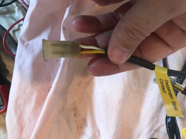
I can get continuity with the wires on the seat sensor when I probe from the back side of the housing, but can't when I probe from the connection/front side of the housing, so think I need to remove the plastic housing so I can clean the contacts. I don't have a spare one of these plastic housings. How does one remove the wires from this particular type of housing (doesn't look to be the same system as the spade connector housings)?
Posted by: bbrock Feb 11 2018, 02:04 PM
I haven't had to remove that one yet, but I believe it is the same principle only on a bullet type connector. I don't remember if there are one or two tangs in there, but look for tabs to press down to let you slide the connectors out the back. I'm sure someone who has done it on these particular connectors will give more specific advice.
I like those wire labels. Is that from a label maker?
Posted by: Jeff Bowlsby Feb 11 2018, 02:29 PM
Its a female hollow tube terminal extractor. I have one, but don't know where to send you the get another...maybe NAPA or someone who sells molex?
Posted by: doug_b_928 Feb 11 2018, 04:39 PM
Thanks guys. I was able to clean the connectors with the housing on to get continuity. Figured maybe I shouldn't mess with that one further until I see if it's a problem.
Next issue: During my ownership the car came with a red GM side marker light as an interior light....Yep... Their connections had fallen apart and most of the requisite wires were not connected. Here's a snip of the wiring diagram for the interior light: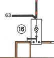
In looking at the wiring diagram, I see what appear to be two power wires: Black with red stripe going to fuse 8, and another black one. I can't tell where the plain black wire goes. Anyone know? I'd like to test its continuity.
There is a brown wire with white stripes that connects to both door switches. I've confirmed continuity to both. There are two ground wires as well. One I could trace to the hazard light switch. I can't tell where the other one goes. I thought from the diagram it might be the fresh air fan but didn't see it there.
All of these wires have their connectors cut off. I have a new aftermarket interior light, as shown below: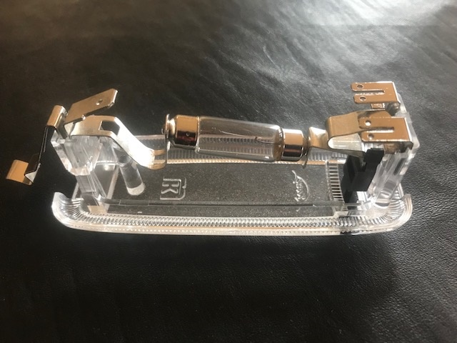
How are the wires to connect to the light? I'm guessing from the diagram that I need to put those small spade connectors on the two grounds and the brown with white stripe and have the latter on one of the double-male connectors on the light and the two grounds on the other double-male connector on the light. Then I need to have the two power wires (black with red and black) going to a single large spade connector that goes on the large male connector on the opposite end of the light. Is that correct?
Posted by: doug_b_928 Feb 11 2018, 04:43 PM
@ Brent...Yes, they are from a label maker. I bought yellow tape thinking it might look nice against the Raveena Green paint (showing more the green tint of the paint).
Posted by: doug_b_928 Feb 11 2018, 05:05 PM
update: I see the unknown ground goes to the ground for the heater blower motor in the engine compartment, so that mystery is solved. Still not sure about the black power wire and how to connect all to the light.
Posted by: Jeff Bowlsby Feb 11 2018, 07:01 PM
See wire 63 on the second page of the schematic. Look for it at the center console. Its unswitched power to the light.
Posted by: doug_b_928 Feb 11 2018, 07:17 PM
Got it. Thanks Jeff!
Looks like I'm there, just need to know how these wires connect to the light. Can anyone comment on my proposed connections above to the light itself?
Posted by: Dave_Darling Feb 11 2018, 10:35 PM
Black to the single terminal on the left. Brown to one of the two on the right; brown/white to the other. Not sure about the black/red wire. Could be crimped into the same female connector as the black one.
The black wire should always be "hot". The brown is always ground, the brown/white is grounded only when one door or the other is open.
--DD
Posted by: 914_teener Feb 11 2018, 11:06 PM
Got it. Thanks Jeff!
Looks like I'm there, just need to know how these wires connect to the light. Can anyone comment on my proposed connections above to the light itself?
Jeff is right...if you have a center console the black wire goes for the console gauge lights.
The spade terminals for the light shown on the picture are for a ground and switched ground. The switched brown wires came with two wires to one spade terminal and go to the two door switches. Test the switches in your doors first. Ask me how I know.
Posted by: doug_b_928 Feb 12 2018, 08:30 AM
Thanks guys. Now I just need to find some of those tiny VW terminal connectors. Which check with my local dealer.
Posted by: bbrock Feb 12 2018, 09:38 AM
Thanks guys. Now I just need to find some of those tiny VW terminal connectors. Which check with my local dealer.
If it's the narrow spades you are talking about, this should be it: https://www.digikey.com/product-detail/en/te-connectivity-amp-connectors/42068/A24745CT-ND/456662
Posted by: doug_b_928 Feb 12 2018, 09:44 AM
Thanks very much Brent. Do you know how to identify the other connectors and insulators for our harness at digikey? Figure if I have to pay shipping might as well get the other items as well instead of splicing in pieces from my spare 74 harness.
Posted by: gothspeed Feb 12 2018, 10:04 AM
The white striped ground wire comes from the driver side door switch. The constant ground and the white striped ground go to the 'switch side' of the dome light.
Posted by: bbrock Feb 12 2018, 10:04 AM
Thanks very much Brent. Do you know how to identify the other connectors and insulators for our harness at digikey? Figure if I have to pay shipping might as well get the other items as well instead of splicing in pieces from my spare 74 harness.
I found the 18-22g terminals work well for the most common wire sizes in the harness. The 14-18g is a little large for the 1.0mm wire. Digikey will also pop small size orders in a USPS envelope so you can keep shipping very cheap.
Posted by: doug_b_928 Feb 12 2018, 01:16 PM
Awesome, thanks!
Posted by: doug_b_928 Feb 13 2018, 09:25 PM
Thanks to Brent I'll be ordering new connectors from digikey tomorrow. In the meantime, the next thing I'm not sure about is the heater light. When I got my car way back when the cover was present and just stuck to the 'astro terf' that was used as carpet... So, not only having a proper interior light but also having a correct and working heater light will be a thrill for me after all of these years. I have a new heater light. Here is the base on the bottom: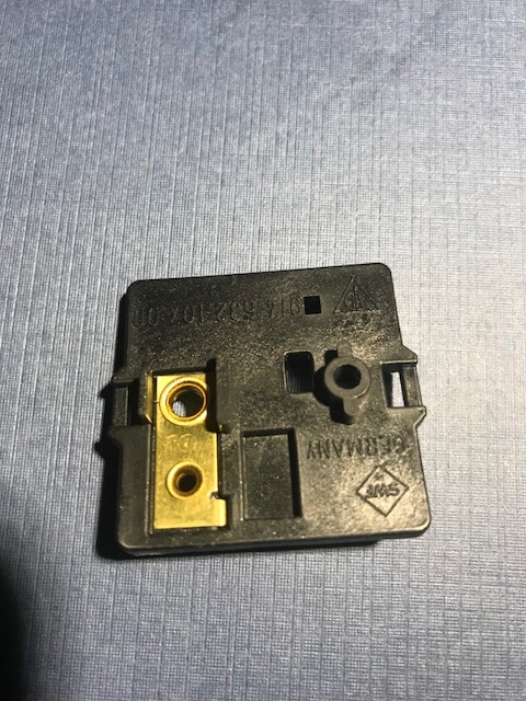
and the topside of the base: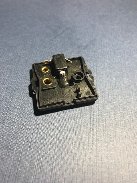
I've already installed a new bulb. I understand from the wiring diagram that a power wire and ground wire will come from the center console gauges. There's a diagram on Jeff's website that appears to be from a different year, but it shows a connector for the ground that would appear to fit under a screw. But in looking at the light base it appears that there are male spades to receive female wire connectors for both positive and ground. So, today's question is, what is the correct connection for this light base? Should a ground wire go directly to the spade connector, or should it go under the screw holding the base down?
Posted by: doug_b_928 Feb 13 2018, 09:54 PM
Another quicker question: I think my car has the harness for the interval wiper motor relay, but did not have a relay. Did all 72-76 cars come with the wiring for it and only the relay itself and hook up was optional? Or, did it have to come with the full option to get the wiring? Hope that makes sense.
PS Jeff's website has a really nice summary of how to hook up the relay.
Posted by: bbrock Feb 14 2018, 12:05 AM
IIRC, there is only a positive wire to the heater light and the mounting screw through the brass eye side IS the ground connection. I'll take a look tomorrow if nobody confirms or denies. Don't get too excited about that light. It just comes on and stays on whenever the headlights are switched on.
On the intermittent wiper, I believe all cars have a terminal to connect the intermittent harness to, but not the harness unless the option is installed. If it isn't, the terminal is folded back onto the harness and wrapped in electrical tape.
Posted by: doug_b_928 Feb 14 2018, 09:05 AM
Thanks as always, Brent. I appreciate you checking into the heater light wiring for me. To go from what was always there, it will still be exciting to have that light present and working the way it originally did.
I had a closer look at the harness that, for some reason, I had labelled intermittent wiper (I probably looked at some documentation and erroneously concluded that must be what it was for). It doesn't look like that's what it was for and I don't recall if I disconnected it from anything but I'm thinking not. It is connected to the fuse panel at the front spade terminal of fuse 9. Then there is a fuse in line, then a branch with a short piece of wire with no connector on it, and then it connects to the rest of the harness pictured below at the spade terminal identified in the picture. The rest is as shown in the pic. Does anyone recognize what this harness would be for? It does look like an original, period correct harness...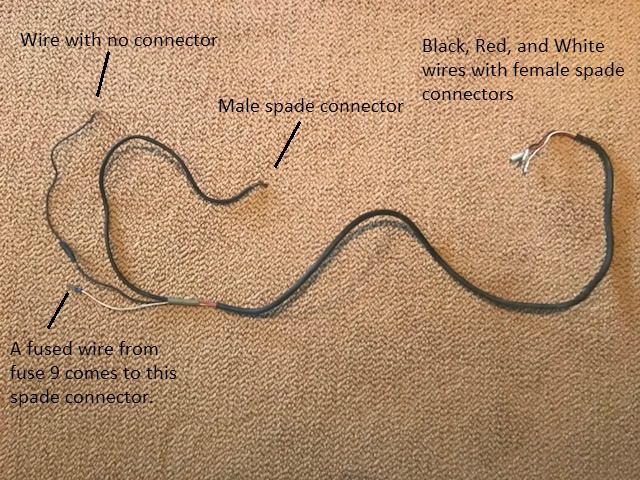
Posted by: bbrock Feb 14 2018, 09:30 AM
Just looked at my harness and confirmed only one wire going to the heater light. In the pic below, the wire to the heater light pigtails out of the connector for the center console illumination. I'm not sure if cars without center console have that connector, but I assume they do. The skinny terminal is connected to the male spade on the heater light, and the circuit is completed to ground through the mounting screw. And I hear you about getting even these "boring" little lights working. I'm the same way 
Looking forward to hearing what the mystery harness is for. I don't have that. First thought is maybe the radio. Look on Jeff's site any of the radio harnesses match? I think those are on the classics section.
Posted by: doug_b_928 Feb 14 2018, 09:53 AM
Thanks, Brent. That also gives me a sense of how long to make that wire (mine was completely destroyed). According to the wiring diagram there is a ground wire that comes from another of those connectors for the centre console to ground at the screw. I guess it just goes between the bottom of the base and the chassis, rather then up inside the base (i.e., between the screw and the base).
Re the harness, I think that mess was in the area under the cowl...so that's probably why I thought it was for the intermittent wiper function...
Posted by: bbrock Feb 14 2018, 10:05 AM
Thanks, Brent. That also gives me a sense of how long to make that wire (mine was completely destroyed). According to the wiring diagram there is a ground wire that comes from another of those connectors for the centre console to ground at the screw. I guess it just goes between the bottom of the base and the chassis, rather then up inside the base (i.e., between the screw and the base).
Re the harness, I think that mess was in the area under the cowl...so that's probably why I thought it was for the intermittent wiper function...
Just a warning, my harness was pretty damaged and I can't remember the original condition of that heater light wire. I know I replaced the spade so no guarantees the length on mine is correct. I'll look again at lunch to see if I'm overlooking a ground wire under that terminal, but it seems totally unnecessary since a metal screw is going to take that side of the circuit straight to ground once it is attached to the chassis.
I did a quick scan of harnesses on Jeff's site (the radio harnesses are in the wiring section, not classics) but didn't see anything that seemed to match what you have. Interesting mystery.
Posted by: bbrock Feb 14 2018, 12:50 PM
Ah! I just looked at the schematic and it looks like the ground wire that goes to the heater light comes off of the center console harness rather than the main. Mine is in a box in the shed on "the back forty," so I can't look at it. But it looks like the ground wire from the main connects into the console harness and then pigtails off to the heater light. I'm not seeing it in the pic on Jeff's harness gallery but it could be hiding in there.
Did you look at the pic of the intermittent harness on his gallery to compare with your mystery harness? Your suspicion may have been correct.
Posted by: doug_b_928 Feb 14 2018, 01:19 PM
Exactly, so I figure I'll just make up a single ground wire with a female spade to connect to the appropriate ground at the main harness and with one of those little connectors with a hole for the screw at the other end of the wire (my car didn't have the center console gauges). Here's the image from Jeff's page. It's not the same schematic in terms of wire color as for our 73s, and on our schematic the black with blue is coming back from a double wire on the male spade in the insulator for the centre console.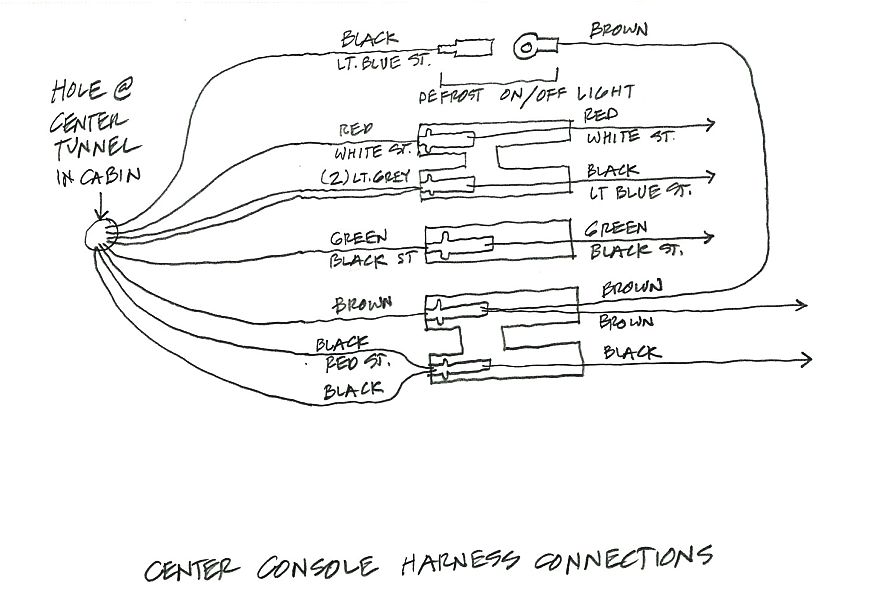
I checked Jeff's page re the intermittent relay wiring and I don't think that's it. There should have been a brown with black lead for that harness and there's no relay socket on it.
Posted by: bbrock Feb 14 2018, 06:12 PM
Exactly, so I figure I'll just make up a single ground wire with a female spade to connect to the appropriate ground at the main harness and with one of those little connectors with a hole for the screw at the other end of the wire (my car didn't have the center console gauges). Here's the image from Jeff's page. It's not the same schematic in terms of wire color as for our 73s, and on our schematic the black with blue is coming back from a double wire on the male spade in the insulator for the centre console.
I checked Jeff's page re the intermittent relay wiring and I don't think that's it. There should have been a brown with black lead for that harness and there's no relay socket on it.
No harm in adding that ground wire with ring connector, but I don't think it is necessary. The brown wire on the main harness side where the center console harness connects, runs back to the interior light (according to the diagram, and then to the chassis ground in the engine compartment. My hunch is the engineers decided to add that pigtail to ground on the console harness to provide a secondary, and closer ground as assurance the gauges would all have a good solid ground. I would further guess they were thinking mostly about the voltmeter although that goes a little counter to the crazy routing they chose to get power to the voltmeter. I'm confident the heater light will work fine with, or without that other ground, but it never hurts to add it.
Posted by: doug_b_928 Feb 17 2018, 09:29 AM
Brent, that was an awesome tip re digikey and thanks again for providing the part numbers. Wish I'd had those connectors earlier. They make things a lot easier.
So back at it today. I haven't figured out the mystery harness but hopefully that will be come clear as I get to that part of the main harness.
One thing I've noticed is that the wire that provides the power for the centre console gauges, and that pigtails power to the heater light, has melted to the other wires it is touching in the harness. It's wire 62 (black with blue striping). Here's the origin of the wire on the wiring diagram: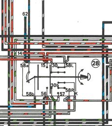
According to this, the wire comes from the 'Light Switch'. When I check for continuity I get it on one terminal on the light switch. But when I pull the wire on that terminal off, I don't get continuity on that wire. The really strange thing is I don't get continuity on any other connectors or wires on that switch, but I know there has to be. Anyway, given that wire 62 has melted in the past, what should I check to make sure that it won't happen again? As I get closer to the fuse panel with that wire should I add another fuse in line to prevent it from damaging the wire if it overheats again?
Posted by: doug_b_928 Feb 17 2018, 12:27 PM
Upon further investigation, things make a bit more sense. The wire for the heater light was pretty much nonexistent at the location where the light would be, the wire was melted up to its power source at the light switch. Someone had spliced in another wire to it about 7 inches back from the headlight switch (with the wrong colour which made it confusing). Here's that splice with butt connector (black with blue in and grey with red out).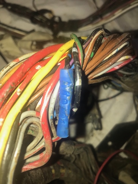
Other wires to/from the headlight switch seem to have been affected by heat. There are others with butt connectors and mismatched wires and a few others had electrical tape wrapped around missing/melted insulation. Here's a view of that: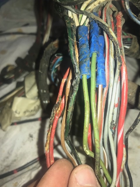
So, does it seem like the wire overheated at the heater light, that wire got really hot, and then shorted by the headlight switch? Or, would it be the reverse with something happening with that wire at the headlight switch and melting other wires around it?
Either way, If I replace everything with good, and hopefully correctly colored, patches of wire, should I be good to go?
Posted by: doug_b_928 Feb 18 2018, 10:59 AM
Today's question: I think I've figured out how I will run the 12G wire through to the steering rack area. I'm going to run a ground from the ground point screw by the frunk release handle to the fuel pump at the steering rack. I have a piece of salvaged ground wire with a ring connector but it appears to be 16G. Given that it's a far shorter run than the 12G + wire, am I ok to ground the fuel pump with the 16G wire? If not I can get a new ring connector and make a piece out of 12G.
Posted by: bbrock Feb 18 2018, 01:35 PM
Today's question: I think I've figured out how I will run the 12G wire through to the steering rack area. I'm going to run a ground from the ground point screw by the frunk release handle to the fuel pump at the steering rack. I have a piece of salvaged ground wire with a ring connector but it appears to be 16G. Given that it's a far shorter run than the 12G + wire, am I ok to ground the fuel pump with the 16G wire? If not I can get a new ring connector and make a piece out of 12G.
![popcorn[1].gif](style_emoticons/default/popcorn[1].gif) I have the exact same question.
I have the exact same question.
Posted by: Jeff Bowlsby Feb 18 2018, 04:06 PM
Fellas, its a circuit. From the power wire, through the pump, to the ground. Its only as good as its weakest link. So a 16 ga ground wire in a 12 ga circuit would be the weak link and may not protect your pump or the + wire.
The stock 75-76 FP ground cable is a stout cable that goes to a screw to the chassis under the fuel tank.
Posted by: doug_b_928 Feb 18 2018, 04:12 PM
Makes sense, thanks Jeff!
PS. Does the mystery harness look at all familiar and anything I need to do to prevent the melted wire issue from the headlight switch?
Posted by: Jeff Bowlsby Feb 18 2018, 04:18 PM
Don't know about the mystery harness. It may be a piece of some other harness, I am not familiar with it. Cannot say about the melted wires - that could have been caused by many things. Two loose power contacts rubbing together, abraided wires in contact, a shorted switch or other component. Just be thorough in your inspection.
Posted by: doug_b_928 Feb 18 2018, 04:21 PM
Perfect, thanks Jeff!
Posted by: doug_b_928 Feb 21 2018, 08:06 AM
My extremely limited knowledge of electronics continues...I'm trying to figure out the relays. A PO had disconnected two wires (going to fuses 2--white and 4--yellow) from the combination relay. I'm putting everything back to stock per the wiring diagram. Here's the diagram for the combination relay: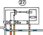
So the wires should connect to the relay as follows:
White = F
Red/white = 56
Yellow = 56a
Yellow/red = S
Here is the schematic on the side of the relay: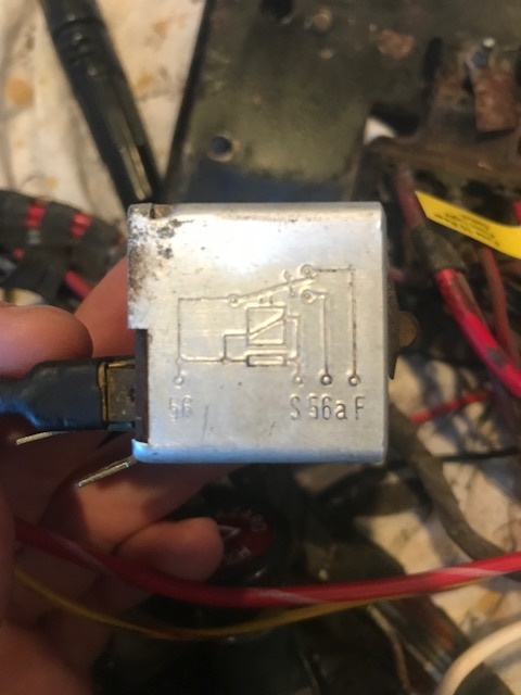
And here are the connectors on the relay: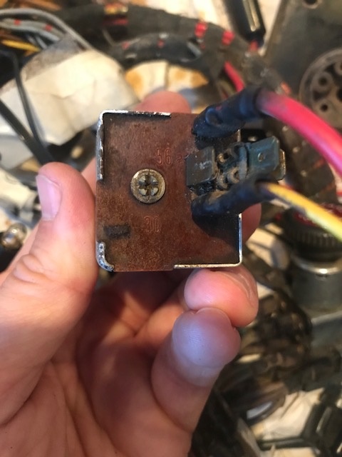
The only code I can see that corresponds to the schematic is 56a, which is the spade in the middle.
So, the question is, how do I know which of the other terminals is which?
Posted by: doug_b_928 Feb 21 2018, 06:36 PM
Hoping someone will chime in about my previous post in terms of how to read the relay schematic so I know which pins are which. In the meantime, the power antenna and radio were wired by soldering in wires with in-line fuses as shown below:
The Radio is wired to Fuse 8 which includes the cigarette lighter.
The antenna is wired to Fuse 11 which includes the interior light.
Is this an appropriate way to power these devices? I'm guessing that Fuse 8 (cigarette lighter) gets power when the key is turned on. But I wonder if Fuse 11 has constant power because it includes the interior light? If so, should I power the antenna from fuse 8 as well or does the radio itself tell the antenna to raise and lower?
Basically, I guess the main question is what's the best way to wire the radio and antenna into the original fuse panel?
Posted by: doug_b_928 Feb 21 2018, 06:46 PM
I just searched some old pictures and it appears the modified wiring originally looked more like this?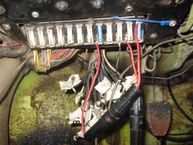
So, it looks like fuse 12 (on the direct connection to battery side) was wired to an inline fuse that then went to the fuse 8. Not sure why they did this.
The antenna was powered from fuse 11
And probably the radio was powered from fuse 10...
So, to instead of figuring out what the PO had done, again, the best way to ask is, what is the correct/best way to wire in power for the antenna and radio?
Posted by: gothspeed Feb 21 2018, 06:53 PM
Today's question: I think I've figured out how I will run the 12G wire through to the steering rack area. I'm going to run a ground from the ground point screw by the frunk release handle to the fuel pump at the steering rack. I have a piece of salvaged ground wire with a ring connector but it appears to be 16G. Given that it's a far shorter run than the 12G + wire, am I ok to ground the fuel pump with the 16G wire? If not I can get a new ring connector and make a piece out of 12G.
If you don't want to buy 12ga wire for this one short run. And if you don't mind appearance in that short distance, you can use three 16ga wires in parallel to the same connectors/lugs. You can heat shrink them together to make the wires look 'neater'. Otherwise just buy some 12ga wire to make it perfect
Here is a wire gauge calculator for length vs amps:
https://www.wirebarn.com/Wire-Calculator-_ep_41.html
Posted by: bbrock Feb 21 2018, 07:45 PM
I just searched some old pictures and it appears the modified wiring originally looked more like this?
So, it looks like fuse 12 (on the direct connection to battery side) was wired to an inline fuse that then went to the fuse 8. Not sure why they did this.
The antenna was powered from fuse 11
And probably the radio was powered from fuse 10...
So, to instead of figuring out what the PO had done, again, the best way to ask is, what is the correct/best way to wire in power for the antenna and radio?
Yeah, it's ugly to say the least. For starters, I'd put female spades on the radio and antenna wires and slide them onto the back of the fuse panel the proper way. There are several slots that have extra lugs for plugging in extras both before and after the fuse in the panel. I don't understand the jumper between fuse 12 and 8. Seems like a bad idea.
Somewhere I thought I ran across which fuse the factory radio harnesses plugged into, but for the life of me can't remember where, nor whether a modern radio would draw more power than whatever the factory or dealer would have installed. If nobody comes to the rescue with an answer, I'd be inclined to leave the inline fused in place, and plug them into whichever fuse has the fattest wire coming from the battery and an extra lug BEFORE the fuse. That way the radio and antenna would be protected with the inline fuses without running current through the fuse on the panel and possibly overloading it. I've never had an automatic antenna, but can't imagine they draw much power and how often are they operating anyway? I'd be inclined to twist the radio and antenna wires together and crimp a single female spade on the pair.
Now let's see if Jeff or anyone jumps in to point out how full of
 I am.
I am.
Posted by: doug_b_928 Feb 23 2018, 07:44 PM
Thanks very much Brent. Yeah, after all of this I definitely want to have a more professional installation. How do I know which terminals on the fuse panel are switched with the ignition?
Other outstanding issues:
1. I still don't know how to connect the wires to the combination relay (as outlined in my post above).
2. I don't yet know what radio I'll get (probably something that looks somewhat period correct but that will allow blue tooth etc), but do most have a power wire for the antenna or is that a separate power going directly from the fuse panel to the antenna?
3. A PO had installed an electric motor for the WW fluid. I understand that originally it would have had a pump that ran off of the air in the spare tire. I'd like to go back to original (this car will be a fair weather driver so electric pump is not necessary).
4. Where was the original button to activate the WW fluid?
5. Also, is the pump pictured below the original pump?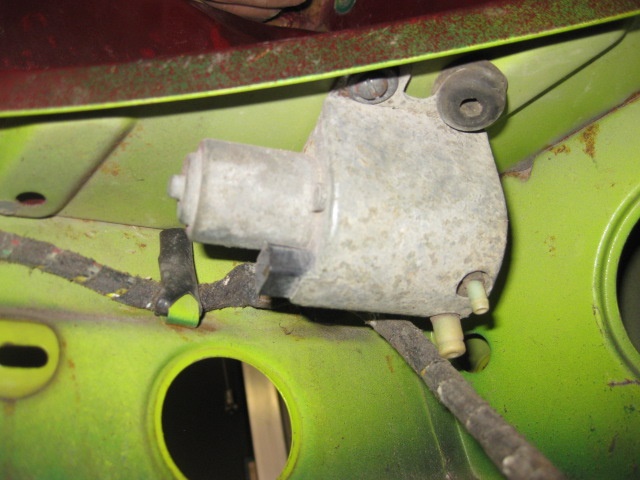
Posted by: doug_b_928 Feb 23 2018, 07:58 PM
Did a little searching and see that there was not washer pump at all originally. I'm guessing what's pictured above was someone's solution to the spare tire pump?
Posted by: Jeff Bowlsby Feb 23 2018, 08:05 PM
If my memory is right the radio clips to Fuse #7 but need to confirm.
That pump looks like it might be the pump for the factory headlight squirter system. If so its golden. Do you have any other parts to that system such as the squirters on the front rubber bumper pad?
Attached File(s) wwpump.pdf ( 94.27k )
Number of downloads: 24
wwpump.pdf ( 94.27k )
Number of downloads: 24
Posted by: doug_b_928 Feb 23 2018, 08:41 PM
Thanks very much as always Jeff. I'll await your confirmation for which fuse to go to for the radio and antenna. Is there a gauge that is best for radios?
I'm thinking now's the time to run wires for an electric washer in case I decide to go that route. The POs method was not pretty. Do you have a recommendation as to what to do to be 'electric WW motor ready' (e.g., where to run the wires, how many, what gauge, etc.)?
I don't recall any other parts as shown in the diagram you attached. Certainly no outlets on the front bumper top, but I suppose that could have been changed though I don't know why since the car is unbent on the front.
Posted by: Jeff Bowlsby Feb 23 2018, 08:56 PM
I know I have seen a harness with the radio at fuse 7, but also found this from the Dr.:
"the factory source was the cigar lighter Many though have tapped the second or third fuse over from the passenger right side so that
they could operate the radio without having to turn the key on"
Posted by: doug_b_928 Feb 23 2018, 09:01 PM
Thanks again Jeff!
As an update, here's a before and after of the fuse panel. It occurred to me that the labels might be an issue. I checked them for continuity and nothing. I assume that means they won't conduct electricity. But are they a fire hazard somehow?
Any chance you can make sense of the connectors on the combination relay above?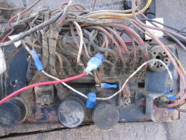
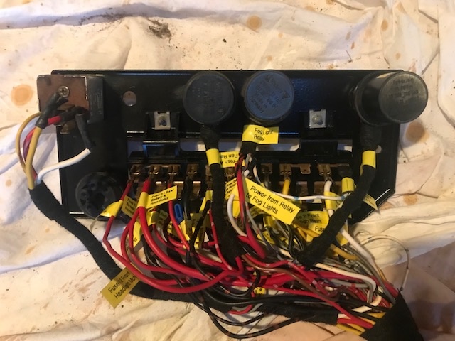
Posted by: Jeff Bowlsby Feb 23 2018, 09:44 PM
Looks good. Hope you see now why I don't recondition these chassis harnesses.
Attached image(s)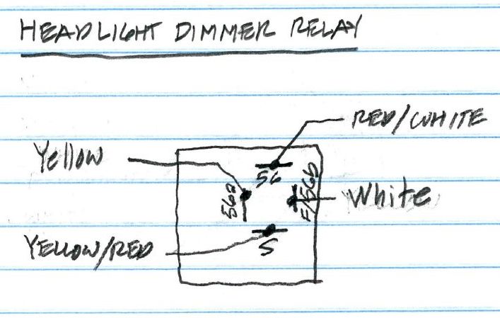
Posted by: doug_b_928 Feb 23 2018, 09:49 PM
Thanks Jeff. So to make sure, no fire issues with the labels? I chuckled with your comment because several times I have thought to myself “now I know why Jeff doesn’t do full harnesses anymore!”
Posted by: Jeff Bowlsby Feb 23 2018, 10:10 PM
I would not label them permanently, but I see no harm.
Posted by: doug_b_928 Feb 23 2018, 10:16 PM
Excellent, thanks Jeff. I'm leaving them for next time I have to go back in there (Don't want to have to through all that again if I can help it).
Posted by: bbrock Feb 23 2018, 11:49 PM
3. A PO had installed an electric motor for the WW fluid. I understand that originally it would have had a pump that ran off of the air in the spare tire. I'd like to go back to original (this car will be a fair weather driver so electric pump is not necessary).
 I'm with you here. People like to "upgrade" to electric pumps, but I think the original system is pure genius and one of my favorite quirks on a car that has so many of them. As you discovered, there is no pump. Just a hose from the spare tire to the fluid bottle, another from the fluid bottle to the switch, and then from the switch to the nozzles. On a '73, the washer is activated by pulling back on the wiper lever. A couple things if you restore it. First, get the right hose. It is under pressure and regular washer tubing will burst and leave you with a wet lap. 914rubber had a bunch of hose kits, not sure if they still do. Second, the connector that screws to the tire has a valve in it to make sure you maintain enough pressure in the tire to use it as a spare. You fill the spare to the max pressure on the sidewall and when you get down to something like 25 lbs. it shuts off.
Other than learning about the hose thing the wet way, I always thought the system worked beautifully even when teeners were out only cars for year round driving.
Nice work on the fuse panel. I'm doing the same with the labels. I'm leaving them on until it is ready to go back in the car.
Posted by: doug_b_928 Feb 24 2018, 05:46 AM
Thanks for WW fluid system explanation, Brent. Do you know if anyone sells a kit with everything to restore it?
I’m thinking I should still run a couple of wires (I’m guessing a positive and ground) for an electric pump just in case. Any thoughts as the appropriate gauge I should add?
My plan is to leave the labels on the whole harness. It will make it easy for the next person in another 50 years. I’m also not leaving gaps between the tape. I think it looks nice that way but after all the work cleaning the wires (which were dirty where they were exposed) I’ll sleep better knowing they will stay clean; and again the next guy will appreciate that someday too
Posted by: doug_b_928 Feb 24 2018, 10:05 AM
Update: I’ve added a couple pieces of wire (look like 16G) for power and ground to the WW pump so I have the option to go electric. I also see the black and brown wire for the intermittent wiper relay. From Sir Andy’s write-up in the tech section it looks to me though like the best way to power the washer is just use the brown/black wire for the intermittent wiper relay. Do I understand correctly that he relay is not needed, rather that wire gets power when the lever on the steering column is pulled (from the write-up it looks like he splices into that wire before the relay location)? Either way I’ll leave the added power wire as a backup.
Posted by: doug_b_928 Feb 24 2018, 02:35 PM
Technical question: the small black with blue wire that gives power to the gauge cluster lights was spanning from the gauges to the fresh air controls from outside the taped harness. It is originally that way, at least for this harness. It would be so much neater to make it a little longer (about 18” at most) and have it follow the loom for the fresh air instead of being a wire on its own getting tangled spanning two branches of the main harness. I measured he resistance in its original configuration as 14 ohms. Then I cut it and spliced in a piece and then rechecked the resistance, finding it to be 24 ohms. I realize that the longer the wire the greater the resistance. But that got me wondering if the factory had it that way to avoid problems with it being a bit longer. Will that change in length of a small wire create any problems?
Posted by: doug_b_928 Feb 25 2018, 10:19 PM
Winter job done (with the exceptions of needing to solder back on the original fuel pump connector once I bring it out of storage, new snorkel, and adding terminals for the new fuel pump and WW wires once I have them trimmed to the correct length). I just wanted to say thanks to all who have replied to my questions in this thread. Your assistance gave me the confidence to get through what I felt would be the most intimidating job of this entire restoration. Also, if anyone who reads this thread has answers to the unanswered questions above, please reply as I'd still like to know the answers. Here's the pic of the final product...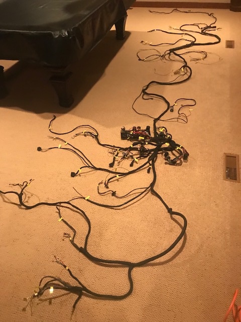
Posted by: bbrock Feb 25 2018, 11:18 PM

Posted by: doug_b_928 Feb 26 2018, 08:47 AM
Thanks Brent. There are two questions that I forgot to ask that are still bugging me a bit:
1. In the wiring for the Fuel Gauge (shown below), there is a brown with white wire that exits and goes through a diode, and from the diode it branches into two wires going to the safety belt warning light and the parking break contact. I could not get continuity through those wires. I removed the diode and could not get continuity through it. I did a little searching and could not see whether or not there should be continuity thorough a diode. But I assumed not. Should there be? Per what I read I tested the resistance in both directions and found different readings in each direction which indicated the diode is good. I'd like to know for sure if it's good before installing the harness back in the car. Is there anything else I should do?
2. The Turn Signal/Emergency Flasher Unit looks like a relay, but the pins are not marked the same as the other relays and when I looked for continuity across any two pins I could not find it. I have a spare from the parts harness and it behaved the same. Is this unit a relay or something else?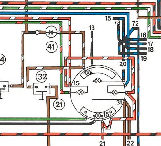
Posted by: doug_b_928 Feb 26 2018, 10:19 AM
Update re testing a diode: I found this youtube video which explains it well. My diode tested at .560 in 1 direction and OL in the other, so hopefully that means it's good .
https://www.youtube.com/watch?v=qSDRsz5-t7I&feature=youtu.be&autoplay=1&rel=0
Powered by Invision Power Board (http://www.invisionboard.com)
© Invision Power Services (http://www.invisionpower.com)