Printable Version of Topic
Click here to view this topic in its original format
914World.com _ 914World Garage _ Alternator question.
Posted by: Olympic 914 Mar 25 2018, 05:05 PM
Took the car out for a drive today, planning on going to dinner. everything is working as it should. getting on the PA turnpike and I had to accelerate briskly to get into traffic, and a moment later I noticed that the RED alternator light had come on. Pulled of at a wide spot to check the belt and wires and shut it off. Not checking the belt with it running. Belt good, plug tight, tapped the VR a couple times for good measure and started it back up. Light still on and now my Autometer AFR gauge just had bars. I know that is because it doesn't turn on until the voltage is +13v So not charging.
Now I am on a limited access highway with the next exit `12-15 miles away. Good thing had the battery fully charged on the tender before I left the house. So I made it to the next exit, turned around and headed back home for a total of 35 miles on battery only. Whew. But that shot dinner.....
Replace the VR with another I had that previously tested good. still no charging. checked the plug on the relay plate again. looks good.
I have not yet checked the wire connections at the alternator, possibly a wire vibrated loose during the brisk acceleration.
Now the question
I read to test the VR to short between D+ and DF and if the alternator is good voltage at the battery will go to alternator maximum of about 15-16V
So do I REMOVE the VR for this test? and jump between the D+ and DF at the relay plate.
OR
Leave the VR in place and short between those pins?
Posted by: Spoke Mar 26 2018, 07:21 AM

Took the car out for a drive today, planning on going to dinner. everything is working as it should. getting on the PA turnpike and I had to accelerate briskly to get into traffic, and a moment later I noticed that the RED alternator light had come on. Pulled of at a wide spot to check the belt and wires and shut it off. Not checking the belt with it running. Belt good, plug tight, tapped the VR a couple times for good measure and started it back up. Light still on and now my Autometer AFR gauge just had bars. I know that is because it doesn't turn on until the voltage is +13v So not charging.
Now I am on a limited access highway with the next exit `12-15 miles away. Good thing had the battery fully charged on the tender before I left the house. So I made it to the next exit, turned around and headed back home for a total of 35 miles on battery only. Whew. But that shot dinner.....
Replace the VR with another I had that previously tested good. still no charging. checked the plug on the relay plate again. looks good.
I have not yet checked the wire connections at the alternator, possibly a wire vibrated loose during the brisk acceleration.
Now the question
I read to test the VR to short between D+ and DF and if the alternator is good voltage at the battery will go to alternator maximum of about 15-16V
So do I REMOVE the VR for this test? and jump between the D+ and DF at the relay plate.
OR
Leave the VR in place and short between those pins?
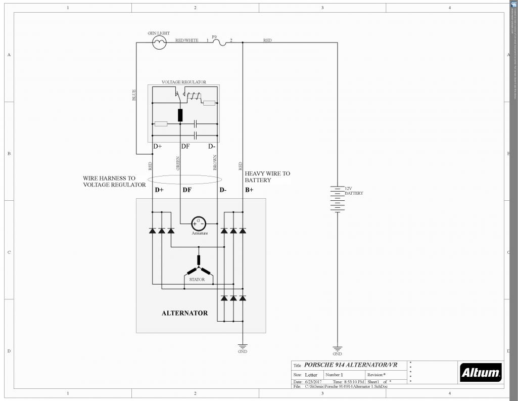
Yes, disconnect only the VR. Jump the D+ and DF pins. See diagram below. Shorting D+ and DF will provide maximum voltage to the armature and thus maximum alternator output.
Only do this test in short bursts as this stresses the alternator and battery to the max.
Attached thumbnail(s)
Posted by: Olympic 914 Mar 26 2018, 08:37 AM
Yes, disconnect only the VR. Jump the D+ and DF pins. See diagram below. Shorting D+ and DF will provide maximum voltage to the armature and thus maximum alternator output.
Only do this test in short bursts as this stresses the alternator and battery to the max.
OK did this test. Removed the VR and placed a jumper wire between D+ and DF on the relay plate. had a Multi tester hooked up and started the engine. tester showed voltage go to 15 , 16 and end around 17V when I shut if off.
so the alternator is good.
Now it gets weird. Plugged one of the voltage regulators back in and now its charging. battery is 12.8 at rest. ( fully charged it last night) and goes to 13.4 running, Gen light goes off. Tried the other VR and same result, but voltage only goes to 13.3
Maybe a bad connection? wires from alternator to plug look good.
I think I will order a new VR anyways. its easy to change....
Posted by: falcor75 Mar 26 2018, 08:47 AM
Ground cable between gearbox and chassi?
Posted by: Olympic 914 Mar 26 2018, 08:55 AM
Ground cable between gearbox and chassi?
New, Cleaned and connected.
Also B+ connection from alternator to starter checked and tight.
Didn't check connections at alternator since you can't get to them with alternator in car. (not easily at least )
Posted by: Mikey914 Mar 26 2018, 09:40 AM
Well if all works well great. I'd try driving it locally a bit.
There is a possibility that you have brushes are going out.
Put it under load (lights on) and drive it for about a half hour. It's rare when something is magically "fixed". Do also look for discoloration from heat on the harness, as this could indicate some damage making connection intermittently.
And by the way you CAN pull the alternator with the engine in the car. It's not bad as long as the screws are not stuck.
Posted by: Olympic 914 Mar 26 2018, 09:50 AM
Well if all works well great. I'd try driving it locally a bit.
There is a possibility that you have brushes are going out.
Put it under load (lights on) and drive it for about a half hour. It's rare when something is magically "fixed".
I will be heading out to do that now. Will carry a multi-tester when I go. Need to get one of those Jump-start boxes just in case.
The alternator was also new when I put it back together, so it has about 2K miles on it now. I understand that doesn't rule it out as a possible problem though. the tail and turn signals are LEDs (Thanks Spoke) and the headlights are Trucklite LEDs. I was trying to lessen the load on the alternator when I put it all back together.
Posted by: Olympic 914 Apr 18 2018, 07:20 PM
So this alternator problem continues to vex me.
tested it by jumping DF and D+ and had good voltage, also tested jumping 12V to DF and also had good voltage. by these tests I ASSUMED the alternator was OK.
it was a rebuilt Bosch AL75X with 2k miles on it.
I just had the engine out for a leaking galley plug and while there replaced the alternator wiring harness with a new one from Bowlsby. I had the Fuching alternator in my hands......
Now during another 300 mile trip the Alt light came on at a about.250 miles. I was stuck in the mother of all traffic jams when I noticed the alt had quit. Not too worried about getting home since I had brought my new jump-box along. but it made it. Stopped for a few minutes at a truck stop about 15 mile from home and when leaving there the alternator started charging again. I had noticed the regulator was very hot and I replaced it with the new Beru unit.
Took it out today for a little 40 mile ride and every thing was fine, decide to take the GF for a ride and before I get out of the driveway..... you guessed it, alt not charging.
Checked the bulb, checked the fuses, ground strap connected, try different relay plate. etc. etc. Ad Nauseam .......
this time when jumping DF and D+ I get NO charge, jump 12V to DF and get 14V
I guess one of the diodes in the alternator gave up the ghost. So now I think the alternator may have been intermittently going. 
 And I had it in my hand.....
I was really working hard to bring this thing to Hershey, but other than bringing it on a trailer it has me beat..
Next step will be to pull the alternator and probably order a new one. Shit...
Posted by: McMark Apr 19 2018, 05:30 AM
Dying relay board?
Posted by: Olympic 914 Apr 19 2018, 06:20 AM
Dying relay board?
I did hook up another relay board I had, and got the same result.
I saw your tutorial on removing the alternator and will be following that. Along with one I found on the Bird board.
To add to the complexity I do have HE and aux blower.
Posted by: malcolm2 Apr 19 2018, 07:08 AM
I have had some ALT probs too. Spoke must keep that how-to and photo on a virtual clip board. 
They seemed to be re-builder problems. The last issue left me stranded. I watched my volt gauge drop and drop and drop to about 8.5 and that was it. Thank goodness I was in a Cracker Barrel parking lot.
Once I dis-assembled the ALT I found what might have been my issue. One of the brushes was not completely centered and 1/8" of it was not wearing down and it was extending in between the 2 copper rings.
I believe the brush was touching something it was not supposed to. anyway here is a photo from my thread.
http://www.914world.com/bbs2/index.php?s=&showtopic=323711&view=findpost&p=2578920
I have a 75 and the HE do make it impossible to get the ALT out. I removed my AUX blower, hell that thing really did not do anything anyway.  I am getting pretty good at removing and installing the ALT now, but what a pain, and all the pieces and parts and sheet metal etc.... What a pain.
Best answer is to buy the best ALT you can and hope it never goes out again.
Posted by: McMark Apr 19 2018, 07:34 AM
I think malcolm2 is right -- and I don't think even Bosch rebuilds are immune. That's one of the reasons I ended up doing an alternator swap using a new manufactured alternator from a company with a good reputation.
Posted by: malcolm2 Apr 19 2018, 08:04 AM
Next step will be to pull the alternator and probably order a new one. Shit...
If you have a rebuilder in your area, maybe they can check yours out and be very careful with it if you go in with some 914world knowledge. Maybe they have some good Google or Yelp reviews.....? Might only take a day vs. getting a questionable re-built one from an assembly line rebuilder in a week.
I say all that only to also say, my last dead ALT came from a mom and pop rebuilder. Turns out Jr was the rebuilder. He knows how to put them together and paint them, but probably is not quite there on the how-and-why skills, especially on these 45 YO alternators. I was the guinea pig.
The unit on my car now was also rebuilt by Jr. at the same time that my dead one. Only $38 bucks each, so I was happy until I had to get a ride home from Cracker Barrel.

Posted by: malcolm2 Apr 19 2018, 09:13 AM
I am bored today. Hey Spoke, how is this???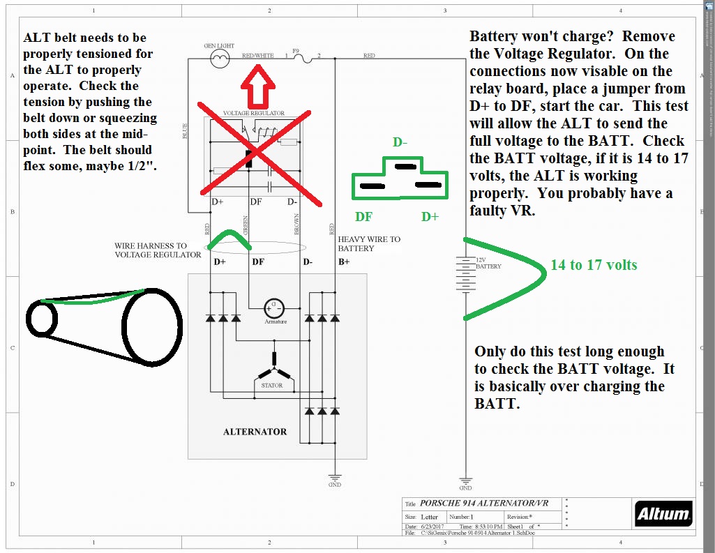
Posted by: Olympic 914 Apr 19 2018, 11:55 AM
There is also this.
I performed the tests below the red line.
There are four connections to the alternator itself. D+, DF,D-, and B+. If you look at the Haynes book, what is not readily apparent, but is true nevertheless, is that the set of diodes that connect to the D+ terminal are a duplicate set (except for lower curent rating) to the ones for the B+ terminal, which is the actual high current output of the alternator. The D+ terminal is therefore a duplicate output terminal of the alternator, with less current capability. The lower set of diodes on current track 80 is common to both the D+ and B+ functions, and forms the ground return for both the B+ and D+ outputs. The DF or "Dynamo Field" terminal connects to the ungrounded end of the alternator field winding, and is an input to the alternator. The current supplied to the DF terminal determines the strength of the magnetic field that penetrates the output windings, and thus controls the alternator's output. The D- terminal is connected to the alternator frame, and is the ground return for the voltage regulator. The other end of the field winding is also connected to ground at this point.
The Bosch alternator is incapable of self-excitation, or "boot-strapping" itself to an operating condition. Older DC generators and some U.S. alternators have residual magnetism retained in the core, or some other scheme to get enough field current to get themselves up and running. The Bosch alternator uses a different scheme. The charge warning lamp is connected between the ignition switch and the D+ terminal. When the car is first started, there is no output from the alternator at either the B+ or D+ terminals. The voltage regulator, sensing no output, is attempting to command maximum field current... it effectively shorts the D+ and DF terminals together. This places the D+ terminal close to ground potential, because the resistance of the field winding is not large. This means that there is +12 volts on one side of the charge warning lamp, and the other side of the lamp is grounded through the alternator field winding. Current thus flows through the lamp, lighting it. This same current, however, also flows through the alternator field winding, producing a magnetic field. This magnetic field is what the alternator needs to start up, and if everything is working correctly, that's exactly what happens. The alternator now begins to develop identical voltages at the D+ and B+ terminals. The D+ terminal is connected to one end of the charge warning lamp, while the other end of the lamp is connected to the battery via the ignition switch. Since the B+ terminal is hard-wired to the battery, and since both the D+ and B+ diodes are fed from the same set of windings in the alternator, no voltage difference can exist between these two points. The warning lamp goes out.
The voltage regulator "watches" the voltage at the D+ point, which should be the same as that applied to the battery. It now changes the short between the D+ and DF terminals into a variable resistance. This effectively controls the field current (whose source is now the output from the D+ terminal, and not the charge warning lamp) and thus regulates the output voltage of the alternator.
Fault conditions: When something happens to the charging system that causes it's output to be insufficient, the result is almost always a net voltage difference across the charge warning lamp, causing it to light. For example: Suppose an output (B+) diode opens. The efficiency of the main output is now considerably reduced. The voltage regulator does not know this, however, because it is looking at the D+ point. So, the B+ output is now lower than the D+ point and the warning lamp lights. Let's say that one of the D+ diodes failed: The D+ output is now reduced considerably. This means that the voltage regulator will have difficulty in maintaining sufficient field current for normal output. The field regulating resistance is low or short (between D+ and DF terminals) and the resulting load on the crippled D+ system drops it's voltage well below the battery voltage. Therefore, there is a net voltage difference across the charge warning lamp and it lights.
The bottom line is that in order for your light to light, you must have a net imbalance in the outputs of the D+ and B+ sections of the alternator (or between the D+ output and the battery voltage, which amounts to the same thing).
________________________________________________________________________________
To trouble-shoot the problem, you need to check the various sections independently. Thus the first check: Connect +12 volts from the battery to the DF terminal on the relay board. This is the maximum field current situation, and should result in maximum output of the alternator. Note that this checks the B+ diodes, the alternator windings, and the common diodes. It does NOT check the D+ diodes.
To check the D+ portion of the system, it is necessary to find out if the D+ output can produce enough current to drive the alternator to full output. To do this, short the D+ and DF terminals on the relay board. This will provide the maximum field current to the alternator that the alternator ITSELF can supply (not the battery, as in the earlier check) and so checks the remainder of the circuitry. If this test puts the light out, then the alternator is good, and the trouble is elsewhere. If it doesn't, then the alternator is almost certainly bad, with one other possibility:
In the Bosch system, the size of the charge warning lamp bulb is critical. Too low a wattage bulb will not supply enough field current for "bootstrap" operation to be reliable. The Bosch book that I have states that the lamps must be at least 2 watts for 12 volt systems. If you have replaced your charge warning lamp recently, then too small a lamp may be your culprit.
Posted by: McMark Apr 19 2018, 04:09 PM
Damn!!! That’s a fantastic post. 
Posted by: bulitt Apr 19 2018, 04:58 PM
Yes, you must excite the Alternator to wake it up. A bulb, resistor or gauge may be used.
Posted by: Edward Blume Apr 19 2018, 05:58 PM
I had my stock Bosch alternator professionally rebuilt for about $250 in Livermore CA. Dean's. Looks pretty too.
Posted by: Mikey914 Apr 20 2018, 10:20 AM
Yes, you must excite the Alternator to wake it up. A bulb, resistor or gauge may be used.
This is why you can't place a LED in the dash warning light. It inhibits the current to create the field as it is a diode.
Posted by: jcd914 Apr 20 2018, 10:36 AM
I don't recall the years but there was a TSB for 911's with certain alternators, that specified installation of a resistor in parallel to the charge indication lamp to boost the current flow thru the alternator for excitation.
We had an alternator/starter shop locally that we used, to avoided any of the rebuilt units available. They turned out a better product that any of out parts suppliers rebuilt units but it took a few days to get them done.
They may still be around I don't know.
Jim
Posted by: Olympic 914 Apr 22 2018, 11:52 AM
On Thursday took the alternator to the local FLAPS and had it tested , they said it had a fault but it passed 3 of 4 tests. still no good. so I ordered another alternator and took the bad one to a reputable local auto / truck electrical shop planning to have it rebuilt and keep as a spare... well they tested it and it and said it was good ??? and all my regulators tested good also.
Reinstalled it and it worked for two seconds, count .. one thousand one, one thousand two. before the alt light came on again....  So I figured I was out of luck for Hershey. No sense going if I can't take the car.
At 10:15 on Friday morning the Flaps called and said the new alternator came in.so I hurried down to pick it up, Installed it, I had a working charging system now, and after a quick ride around the block, headed off to Hershey.
Where I picked up ANOTHER regulator. this one a Bosch solid state.
So 450 miles later everything is working fine.... Finally...
I guess the alternator was the problem all along but intermittently working, Now I have a bunch of spare regulators and a new Bowlsby wiring harness.
Thanks for your help and suggestions.
Tom
Posted by: Spoke Apr 22 2018, 12:07 PM

Posted by: GregAmy May 13 2018, 01:22 PM
That post #15 is a gem...
Camping onto this one for a slightly different problem: GEN light comes on strong with key on, engine not running, But then the GEN light glows very soft at idle, and then comes on stronger as RPMs build. Battery is getting ~13.5 volts when running.
Check. I get around 15.5V at idle and up to 17+ as I rev it up.
Check. Same as above, 15+ V at idle and 17+ as I rev it up.
Problem is, I can't check to see if it extiguishes the GEN light, because my GEN light is not on with the voltage regulator removed. It'll only come on with the regulator installed. This makes sense, because looking at the wiring diagram the ground side of the GEN light is through the voltage regulator; it's blocked by diodes at the alternator from grounding.
Does everyone else's GEN light come on with key on and engine off when the VR is removed?
I did some further checks. Pulled the combo gauge out and measured voltage at the GEN light housing. With the engine off I'm getting 0V across the terminals, but with the engine running I'm getting ~2V at idle with the blue (D+) wire hotter than the red (system) voltage wire, rising to nearly 4V at revs. Measured to ground, I'm getting system (~13.5V) voltage from the S9 fuse and ~15.5V at idle and ~17.5V (max alternator output) at the blue D+.
That would certainly explain the glowing bulb.
So here's the key question: what is supposed to be at D+? I'm guessing the same as system. B+ is being regulated, so the rest of the car is getting the proper voltage, it's just the D+ wire that's too hot. Unfortunately, I don't know enough about these systems to understand why that could happen.
Since the rest of the car is not overcharging it seems safe to drive, and it'll still glow bright if I fail the alternator, but I'd prefer to not ignore it.
I REALLY don't want to replace the alternator in this thing...Thoughts appreciated.
Greg
Edit: an added data point. I swapped out the Hella solid state VR for a resgular Bosch VR of unknown provenance. Now I'm getting 13.5 on the D+ side and 12.2 on the B+ side. I might just buy a new VR from a local FLAPS and see if that resolves it.
Posted by: Spoke May 13 2018, 02:20 PM
Does everyone else's GEN light come on with key on and engine off when the VR is removed?
Yes, the light is on with key on and engine not running and off with VR removed.
Measured to ground, I'm getting system (~13.5V) voltage from the S9 fuse and ~15.5V at idle and ~17.5V (max alternator output) at the blue D+.
That would certainly explain the glowing bulb.
I'm not sure I follow your measurements. What are the 2 measurements at S9 and D+ both to ground at the same condition with the VR installed? At idle and 2k RPM. The difference between the voltage at S9 and D+ is the voltage across the GEN light.
These 2 voltage come from the 2 steering diode pins on the alternator which derive voltage from the same stator windings. They should always be the same during operation. This could point to alternator diode issue although I wouldn't replace the alternator unless sure it's not the VR. It would be convenient to swap the VR for a known good one before buying a new VR.
So here's the key question: what is supposed to be at D+?
D+ doesn't matter in this case. D+ is the voltage across the armature to provide field current for the armature coil. It will vary with load. The VR controls this.
Since the rest of the car is not overcharging it seems safe to drive, and it'll still glow bright if I fail the alternator, but I'd prefer to not ignore it.
Agreed it should be ok as long as the battery voltage stays above 13V and below 15V.
Posted by: GregAmy May 13 2018, 03:45 PM
How? Look at the wiring diagram: if you remove the voltage regulator then to what circuit will the GEN lamp ground? The diodes in the alternator should stop it from being grounded there, leaving only the circuits in the voltage regulator...so, to the wiring diagram, the GEN light should not be on with the VR removed and the key on.
Have you observed it that way yourself? If not, give it a try.
Exactly as I wrote above: "Measured to ground, I'm getting system (~13.5V) voltage from the S9 fuse and ~15.5V at idle and ~17.5V (max alternator output) at the blue D+."
Direct to battery using the same ground is within 0.2V of S9, as measured on the S9 side of the GEN light housing.
"Should".
Ain't.
Posted by: Spoke May 13 2018, 05:30 PM
How? Look at the wiring diagram: if you remove the voltage regulator then to what circuit will the GEN lamp ground? The diodes in the alternator should stop it from being grounded there, leaving only the circuits in the voltage regulator...so, to the wiring diagram, the GEN light should not be on with the VR removed and the key on.
Have you observed it that way yourself? If not, give it a try.
Exactly as I wrote above: "Measured to ground, I'm getting system (~13.5V) voltage from the S9 fuse and ~15.5V at idle and ~17.5V (max alternator output) at the blue D+."
Direct to battery using the same ground is within 0.2V of S9, as measured on the S9 side of the GEN light housing.
"Should".
Ain't.
I re-read my post and I had a few things wrong.
= With VR removed and engine not running, S9 is battery voltage (12.6V). The load looking into the D+ wire is infinite since the VR is the only load. and with the VR removed, electrically you only see the cathodes of the 3 alternator diodes. The GEN light doesn't light since current cannot flow into the cathodes of the 3 diodes.
= I said the voltage at D+ doesn't matter. I had confused D+ with DF. D+ should be exactly the same as the battery voltage. DF is variable with load and is controlled by the VR.
= About the measurements, here's what I think you've measured with the VR INSTALLED:
At idle:
V(S9) V(D+)
13.5V 15.5V
At elevated RPM
V(S9) V(D+)
13.5V 17.5V
Or are these numbers with VR REMOVED and D+ directly connected to DF?
Posted by: euro911 May 14 2018, 02:27 AM
I have several 'unknown condition' units I need to check out. I took one to Autozone several years ago and they said their machine didn't have the correct connector to test a type-4 alternator 
Posted by: GregAmy May 14 2018, 05:05 AM
= About the measurements, here's what I think you've measured with the VR INSTALLED:
At idle:
V(S9) V(D+)
13.5V 15.5V
At elevated RPM
V(S9) V(D+)
13.5V 17.5V
Or are these numbers with VR REMOVED and D+ directly connected to DF?
I am going to check these again tonight. But the S9 and D+ measurements at the GEN bulb housing were with VR installed; the only VR-out checks I did were for the tests in post #15, where I connected B to D+ and jumped D+ to DF; both tests showed max alternator output, ~17.5 volts.
I wish I knew alternators better (that's some serious magic, like CV joints and rotary engines) but it makes no sense that I'm seeing system/battery voltage on S9 but what seems to be max alternater output on D+.
More data tonight.
Posted by: GregAmy May 14 2018, 03:55 PM
= About the measurements, here's what I think you've measured with the VR INSTALLED:
Prior to start up
12.15V at the battery.
Voltage between from combo gauge housing (my ground inside) to battery 12.15
Key on, removed bulb:
11.83V between combo housing and red/white wire
0V between combo and blue wire
So my S9 circuit has a dirty connection somewhere, I'm losing 1/2V to the combo gauge.
Bulb back in, start car:
13.35V battery to combo gauge housing
13.32V between combo housing and red/white wire @ idle
~15.5v between combo housing and blue wire @ idle
Bulb glowing slightly
13.51V between combo housing and red/white wire @ revved
17.34V observed between combo housing and blue wire @ revved
Bulb glowing brighter, but not as bright as key on engine off.
Reminder: when I tested Battery to D+ and DF to D+ I got max alternator voltage both times.
So why is D+ showing max alternator output voltage when it's supposed to be the same as B+?
I'm'a gonna hit a FLAPS for a new voltage regulator, not really hopeful but fingers crossed.
Posted by: GregAmy May 14 2018, 04:32 PM
Aaaaand a new voltage regulator...
...didn't resolve it. Same problem. Wish I understood alternators better so I could understand the problem, but oh well. And I get to replace the alternator pigtail with a new one.
At least now I have a spare VR. Odd one too, from Echlin, remote mounts.
Who makes our preferred alternator so I won't have to do that job again? I've done it once before and I remember it was a fiddly job.
Dammit.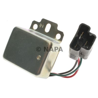
Posted by: Spoke May 15 2018, 07:04 PM
Bummer. I didn't think the VR was at fault but it is an easy swap to find out.
Are all the ground straps (Battery to chassis; chassis to transmission) clean and tight?
Posted by: GregAmy May 16 2018, 06:42 AM
Yep. All grounds and battery cables replaced by me a couple years ago.
Have not replaced the alternator pigtail though. I wonder if that's accessible with the alternator in the car?
Posted by: dangrouche May 17 2018, 11:27 AM
Yep. All grounds and battery cables replaced by me a couple years ago.
Have not replaced the alternator pigtail though. I wonder if that's accessible with the alternator in the car?
the pigtail at the alternator end needs the alternator removed, and the metal cover shield removed as well.

HERE IS METHOD TO TROUBLESHOOT THE INSTALLED ALTERNATOR:
I did have a complete functional alternator assembly(alternator with the pigtail connected). I attached an alligator clip to the "extra alternator" body and grounded it to the car. I also did the same by connecting the positive terminal of the the external alternator to the car battery terminal. I plugged in the pigtail of the extra alternator onto the relay board. I switched the ignition key to the "on" position. I looked at the idiot light to see whether it glowed or not. (It did not glow with the installed alternator. ) The idiot light DID glow with the extra alternator, which meant installed alternator was failed (diode or brushes).
At least this way, I did not have to go to the trouble of pulling and testing the installed alternator. In the end, I rebuilt the installed alternator for $15 with a pair of alternator brushes from RockAuto.
Posted by: GregAmy May 18 2018, 08:07 AM
Yeah. I had the race car on the lift so looked it over last night and it needs to be removed.
I've got a spare alternator on the bench, one removed some time ago, so I'm looking around to see if I can find someone to rebuild it. I'm in no rush; as noted before, best I can tell the only thing connected to the 17V on the D+ side is the GEN lamp, and with system at 13.5V it won't hurt anything for now while I get a replacement lined up.
Posted by: dangrouche May 18 2018, 11:24 AM
https://www.aspwholesale.com/index.php
here is a website that sells the bearings and brushes parts if you are up to rebuilding it yourself
Posted by: GregAmy Mar 25 2019, 07:58 PM
Camping onto this one for a slightly different problem: GEN light comes on strong with key on, engine not running, But then the GEN light glows very soft at idle, and then comes on stronger as RPMs build. Battery is getting ~13.5 volts when running.
So why is D+ showing max alternator output voltage when it's supposed to be the same as B+?
Quick follow up: alternator replacement solved it. I'm guessing a bad diode.
That's such a hateful job...
Posted by: worn Mar 25 2019, 08:13 PM
Camping onto this one for a slightly different problem: GEN light comes on strong with key on, engine not running, But then the GEN light glows very soft at idle, and then comes on stronger as RPMs build. Battery is getting ~13.5 volts when running.
So why is D+ showing max alternator output voltage when it's supposed to be the same as B+?
Quick follow up: alternator replacement solved it. I'm guessing a bad diode.
That's such a hateful job...
Maximum alternator output is triggered when you bypass the voltage regulator. The battery voltage is the same as the alternator voltage because the two are coupled by large wires. The alternator pushes charges into the battery, and the battery pushes back. The voltage produced by the battery matches the voltage produced by the alternator.
Have no good explanation for the charging light.
Haven’t much liked pulling and replacing the alternator either...
At home or far afield. I will say that Ockteenerfest is a good place to get parts though...
Posted by: GregAmy Mar 26 2019, 05:06 AM
Maximum alternator output is triggered when you bypass the voltage regulator. The battery voltage is the same as the alternator voltage because the two are coupled by large wires. The alternator pushes charges into the battery, and the battery pushes back. The voltage produced by the battery matches the voltage produced by the alternator.
Have no good explanation for the charging light.
It makes more sense if you read the back story (this page); I didn't quote it all because it's tedious...but short version, battery voltage (B+) was 13.5V but D+, the wire going to the dash gen light, was max voltage at 17.4V at RPM. They're supposed to be the same. So because D+ was more than B+, the gen light came on. It was dim at idle and got brighter with revs because the alternator was putting out more D+ with more RPM, while the voltage regulator was controlling B+ around 13.5 (4V differential).
The D+ wire only goes to the gen light, so it didn't hurt any systems to run it that way all last year. But it was an annoyance. I have the engine out of the race car for freshening so I chose to install its alternator into the street car, given the race car doesn't use the gen light or wire at all...but it might make a lot of sense to get it rebuilt before installing on the engine, since it's such a hateful job to replace it later...
Posted by: DRPHIL914 Mar 27 2019, 10:33 AM
Camping onto this one for a slightly different problem: GEN light comes on strong with key on, engine not running, But then the GEN light glows very soft at idle, and then comes on stronger as RPMs build. Battery is getting ~13.5 volts when running.
So why is D+ showing max alternator output voltage when it's supposed to be the same as B+?
Quick follow up: alternator replacement solved it. I'm guessing a bad diode.
That's such a hateful job...
Greg,
Glad you solved it. My issue was the lacke of a good ground due to the fan housing being powder coated , a new ground wire direct from the alternator to the body solved it. Something to keep in mind if you ever paint your engine tin and fan shroud!
I think it was Zach who had a similar issue that suggested this to me.
Phil
Posted by: VaccaRabite Mar 27 2019, 07:39 PM
Greg,
Glad you solved it. My issue was the lacke of a good ground due to the fan housing being powder coated , a new ground wire direct from the alternator to the body solved it. Something to keep in mind if you ever paint your engine tin and fan shroud!
I think it was Zach who had a similar issue that suggested this to me.
Phil
Yup. powder coating the doghouse makes it look good, but sucks for the alternator. I chased my tail over that for a LONG time last summer.
Zach
Posted by: Tdskip Mar 28 2019, 06:13 AM
I think malcolm2 is right -- and I don't think even Bosch rebuilds are immune. That's one of the reasons I ended up doing an alternator swap using a new manufactured alternator from a company with a good reputation.
I’ve gotten bad rebuilt ones, not unheard of unfortunately.
Posted by: Gatornapper Aug 31 2019, 07:07 PM
Ok, friends - this thread has been very helpful, but my situation is a bit different from any listed here.
New gel battery, resting voltage, 12.6. Ground connections good.
Gen Light:
* Comes on very bright as it should with ignition on, engine not running.
* Completely goes out when engine is running. No, it's not even dim.
* Comes on dim when headlights are on.
* MAXIMUM charging voltage with engine running, no loads except ignition, is 12.2, very slowly drops over time; drops to 11.9 with headlights on, slowly continues to drop over time. Strong battery lets me drive for 30 min with headlights on.
* Gen light never comes on bright when engine is running; only when engine is off.
So, alternator is not charging - OR, VR is not adjusting voltage for load.
DID THE D+ TO DF Jumper TEST: at rpm, voltage at battery jumps to 16.9 to over 17.
So alternator is good, right?
Purchased NOS regulator from great fellow member here.
My original VR and the NOS VR both perform exactly the same....no charging. Gen light is OFF unless I turn headlights on, then is dim. Engine running with either VR is 12.2, and seems to stay there for some time.
So it seems to me that there is some charging going on - just not enough.
Been doing auto electrics for almost 50 years and never seen this one. Never seen a VR/alternator problem before I couldn't diagnose and repair.
Oh - would the wrong size Gen lamp cause this? Seems the correct size to my by the way it is functioning......but hey, what do I know?
Oh- ordered a cheap new VR from Rock Auto to use as a test unit, but it won't be here for 10 days - like to have the car ready for the local 9/14 - 914 event.
TIA,
GN
Posted by: Spoke Aug 31 2019, 08:14 PM
Try these measurements with engine running; lights on and lights off.
D+ to chassis ground. Should be 14V
D- to chassis ground. Should be 0V
DF to chassis ground. Should be 5-9V
Battery POS post to chassis ground. Should be 14V
Battery NEG post to chassis ground. Should be 0V
D+, D-, DF can be measured in the plug coming from the alternator. Measure to chassis, not engine case or tin.
When did this start happening? Did you do any work on the car?
Posted by: Gatornapper Sep 1 2019, 07:20 AM
Only work on car had nothing to do with electrical. Problem has been there since I first ran engine a couple months ago - I've not been driving the car much and have been focused on other more important mechanical needs - like brakes.
Should I read these voltages at the VR pins as well? Or only the alternator plug? BTW, I cleaned both after the NOS VR did not produce proper voltage. Seem the relay board has to be good to get the 17v with D+ & DF jumped, right?
Car sat for almost 14 years......
Thanks for all these voltages to check - will do tomorrow.
GN
Try these measurements with engine running; lights on and lights off.
D+ to chassis ground. Should be 14V
D- to chassis ground. Should be 0V
DF to chassis ground. Should be 5-9V
Battery POS post to chassis ground. Should be 14V
Battery NEG post to chassis ground. Should be 0V
D+, D-, DF can be measured in the plug coming from the alternator. Measure to chassis, not engine case or tin.
When did this start happening? Did you do any work on the car?
Posted by: 914Sixer Sep 1 2019, 07:41 AM
Do you have a spare relay board to swap out?
Posted by: Spoke Sep 1 2019, 07:48 AM
Should I read these voltages at the VR pins as well? Or only the alternator plug? BTW, I cleaned both after the NOS VR did not produce proper voltage. Seem the relay board has to be good to get the 17v with D+ & DF jumped, right?
The voltage can be measured with the alternator plug connected to the relay board as in normal operation thus you'll also be measuring the VR pins. The nice part about these measurements is you don't have to set up anything difficult, just measure the voltages at the plug WRT chassis ground.
About the relay board, I have heard of guys having issues with the relay board because the VR or alternator plug pins pushing through to short out to ground or whatever is below the pins. Not sure how to test these. Maybe someone can chime in who has faced this issue.
Posted by: Gatornapper Sep 1 2019, 11:36 AM
I have quite a bit of experience with circuit boards, so if our voltage read-outs don't help, I can trouble-shoot the relay board too.......
GN
About the relay board, I have heard of guys having issues with the relay board because the VR or alternator plug pins pushing through to short out to ground or whatever is below the pins. Not sure how to test these. Maybe someone can chime in who has faced this issue.
Posted by: Gatornapper Sep 3 2019, 06:26 PM
Spoke -
Ran tests tonight after 1 hour drive, so nominal battery voltage at time of test was 12.2 v, not my normal 12.6
Results of Lights Off in Blue; Lights ON in Red. All readings to chassis ground from VR pins.
So what does this tell you? Clearly something major is wrong as the DF voltages are no different from the D- voltages. But when D+ and DF were jumped, battery voltage was about 17v....
Bad relay board? No, do not have another....
TIA,
GN
Try these measurements with engine running; lights on and lights off.
D+ to chassis ground. Should be 14V 11.73v 10.89
D- to chassis ground. Should be 0V .015v -.004v
DF to chassis ground. Should be 5-9V .015v-.004v
Battery POS post to chassis ground. Should be 14V 12.2v
Battery NEG post to chassis ground. Should be 0V 0v
D+, D-, DF can be measured in the plug coming from the alternator. Measure to chassis, not engine case or tin.
Posted by: 904svo Sep 3 2019, 07:28 PM
Just a WAG, measure the voltage between the alternator and the engine case with the engine running. There should be less than 1 volt. If its over 1 volt you have a grounding problem.There is a problem between the alternator and the engine case, there
should be a ground strap between the alternator and the engine caseto correct this problem.
Posted by: Spoke Sep 3 2019, 07:34 PM
Spoke -
Ran tests tonight after 1 hour drive, so nominal battery voltage at time of test was 12.2 v, not my normal 12.6
Results of Lights Off in Blue; Lights ON in Red. All readings to chassis ground from VR pins.
So what does this tell you? Clearly something major is wrong as the DF voltages are no different from the D- voltages. But when D+ and DF were jumped, battery voltage was about 17v....
Bad relay board? No, do not have another....
TIA,
GN
Try these measurements with engine running; lights on and lights off.
D+ to chassis ground. Should be 14V 11.73v 10.89
D- to chassis ground. Should be 0V .015v -.004v
DF to chassis ground. Should be 5-9V .015v-.004v
Battery POS post to chassis ground. Should be 14V 12.2v
Battery NEG post to chassis ground. Should be 0V 0v
D+, D-, DF can be measured in the plug coming from the alternator. Measure to chassis, not engine case or tin.
I assume the GEN light is off? It looks like there is no activity from the VR. DF drives the alternator armature and with 0V on DF thus 0V on the armature, the alternator is technically off and not running. You might want to check the resistance from the VR pins to the alternator plug just to make sure DF connects to DF, D+ to D+, and D- to D-.
If the VR pins to alternator plug resistances are good (0 ohm), then I would suspect the VR.
Posted by: Gatornapper Sep 3 2019, 07:37 PM
Thanks for the idea - I'll do that. But previously I've checked all grounding connections and they are all good. Completely refurbished the one from the battery negative terminal to the chassis......
Another good point to measure is from the alternator mounting strap to the chassis and to the engine case while running.....I'll do that one too. All should be way less than 1 volt.....really zero.
GN
Just a WAG, measure the voltage between the alternator and the engine case with the engine running. There should be less than 1 volt. If its over 1 volt you have a grounding problem.There is a problem between the alternator and the engine case, there
should be a ground strap between the alternator and the engine caseto correct this problem.
Posted by: Gatornapper Sep 3 2019, 08:08 PM
Spoke - yes, GEN light is OFF until I turn on headlights, then on, but very dim.
I will check for zero resistance between the VR pins and the alternator pins -
Thank you.
If all is well with the relay board, I have a bad VR that came with car and a bad NOS one I just bought from a forum member - who will refund my money if I want. First I want to make sure the NOS one is bad as well.
AND I have a cheap (Chineses I suspect) one coming next week from Rock Auto I got just for a point of reference.
Thanks!
GN
Spoke -
Ran tests tonight after 1 hour drive, so nominal battery voltage at time of test was 12.2 v, not my normal 12.6
Results of Lights Off in Blue; Lights ON in Red. All readings to chassis ground from VR pins.
So what does this tell you? Clearly something major is wrong as the DF voltages are no different from the D- voltages. But when D+ and DF were jumped, battery voltage was about 17v....
Bad relay board? No, do not have another....
TIA,
GN
Try these measurements with engine running; lights on and lights off.
D+ to chassis ground. Should be 14V 11.73v 10.89
D- to chassis ground. Should be 0V .015v -.004v
DF to chassis ground. Should be 5-9V .015v-.004v
Battery POS post to chassis ground. Should be 14V 12.2v
Battery NEG post to chassis ground. Should be 0V 0v
D+, D-, DF can be measured in the plug coming from the alternator. Measure to chassis, not engine case or tin.
I assume the GEN light is off? It looks like there is no activity from the VR. DF drives the alternator armature and with 0V on DF thus 0V on the armature, the alternator is technically off and not running. You might want to check the resistance from the VR pins to the alternator plug just to make sure DF connects to DF, D+ to D+, and D- to D-.
If the VR pins to alternator plug resistances are good (0 ohm), then I would suspect the VR.
Posted by: Gatornapper Sep 4 2019, 06:21 AM
Re: VR not working.
Both VR's I have get very hot - too hot to touch. So it seems that they are trying to work - lot of activity going on electrically to produce all that heat......
Posted by: Olympic 914 Sep 4 2019, 06:45 AM
Re: VR not working.
Both VR's I have get very hot - too hot to touch. So it seems that they are trying to work - lot of activity going on electrically to produce all that heat......
I had two original regulators that were tested as good at a auto electric shop and both of them would get hot when running. That may be why there is a hole in the relay board under the regulator, to let some air get in there.
I purchased a solid state regulator from BERU. and it works perfectly and does not get hot. you have to modify the mounting holes on the BERU unit and trim the plastic relay board cover for it to fit but when mounted you can't see the modification to the cover.
I think the BERU unit was $25-30
Posted by: Gatornapper Sep 4 2019, 09:42 AM
Thanks - would like to get one....
Checked BERU's site, cannot get to where I can purchase a unit......entered United States, and my zip code - got nothing......
I had two original regulators that were tested as good at a auto electric shop and both of them would get hot when running. That may be why there is a hole in the relay board under the regulator, to let some air get in there.
I purchased a solid state regulator from BERU. and it works perfectly and does not get hot. you have to modify the mounting holes on the BERU unit and trim the plastic relay board cover for it to fit but when mounted you can't see the modification to the cover.
I think the BERU unit was $25-30
Posted by: euro911 Sep 4 2019, 11:43 AM
Typically can't purchase products from companies' web sites ... need to purchase items from retail vendors
https://www.autohausaz.com/pn/12181365-90160320602?utm_source=google&utm_medium=cpc&utm_campaign=feed_Porsche& amp;gclid=Cj0KCQjwwb3rBRDrARIsALR3XeaylFd6IGznsURHGrguusp_7uiQkGzjZksNDzUFrH_o_s
2_cvYI0hgaAiXcEALw_wcB
Posted by: Gatornapper Sep 4 2019, 05:21 PM
Thanks Mark.
Typically can't purchase products from companies' web sites ... need to purchase items from retail vendors
https://www.autohausaz.com/pn/12181365-90160320602?utm_source=google&utm_medium=cpc&utm_campaign=feed_Porsche& amp;gclid=Cj0KCQjwwb3rBRDrARIsALR3XeaylFd6IGznsURHGrguusp_7uiQkGzjZksNDzUFrH_o_s
2_cvYI0hgaAiXcEALw_wcB
Posted by: Gatornapper Sep 4 2019, 05:28 PM
Ok, test results:
Relay board not the problem......zero resistance between the D+, D-, and DF at the VR contacts and their matching points at the cable to the alternator end. No corrosion or even dust at any of the contact points - but then I had cleaned them with electrical contact cleaner anyway.
Also, voltage between battery ground and engine while running is .007 volt......essentially nothing.
Ran separate ground from engine to chassis, no change in anything.
Only thing left is the VR as far as I can see things......
Long wait until next Tuesday.
GN
Posted by: jcd914 Sep 4 2019, 05:53 PM
Maybe I missed in the thread but did you check voltage between the alternator body and the engine case? Should be zero.
The alternator grounds to teh engine through the mounting to the engine, unless someone has added a ground strap.
There have been a few cases of painted or powder coated alternator bodies and/or mounting brackets that were preventing a good ground for the alternator.
Good luck
Jim
Posted by: Spoke Sep 4 2019, 07:06 PM
Re: VR not working.
Both VR's I have get very hot - too hot to touch. So it seems that they are trying to work - lot of activity going on electrically to produce all that heat......
Just to check: both VR's get very hot but both do not work and no charging is going on, correct? No charging means you see less than 12.6V while running.
It is odd that 2 VR's both do the same thing (get hot) but don't work. However when you short DF to D+ you get full charging from the alternator.
One more thing to check with engine off, check: remove the VR and disconnect the alternator cable. Then check resistance between D+ to DF, D+ to D- and D+ to D-. Just make sure there are no shorts on the relay board. All should be infinite.
Also measure resistance D+ to chassis; DF to chassis; and D- to chassis. All should be infinite although D+ might show some resistance as D+ is connected to the GEN bulb and to stuff on the other side of the bulb.
Again looking for shorts to ground. Just want to make sure there are no shorts on the relay board.
Posted by: Spoke Sep 4 2019, 07:24 PM
Ok, test results:
Relay board not the problem......zero resistance between the D+, D-, and DF at the VR contacts and their matching points at the cable to the alternator end. No corrosion or even dust at any of the contact points - but then I had cleaned them with electrical contact cleaner anyway.
Also, voltage between battery ground and engine while running is .007 volt......essentially nothing.
Ran separate ground from engine to chassis, no change in anything.
Only thing left is the VR as far as I can see things......
Long wait until next Tuesday.
GN
Good to check voltage from battery ground to engine is low. For the alternator, the important measurement is from the alternator case to battery ground/chassis. By measuring D- to chassis before you have done this test. See the schematic below. Notice the D- wire at the VR goes into the alternator and directly to ground. That ground is actually:
The alternator case to fan shroud to engine case to transmission case to transmission wire strap to chassis ground.
So measuring D- to chassis measures the total voltage drop of all those components. If you see less than about 0.2V drop from D- to chassis while the alternator is working, the alternator is properly grounded.
Keep in mind that without the alternator working, there is no current in the alternator to chassis ground so a zero volt reading would be expected even if the alternator ground is not good. The best way to ground the alternator is to run a wire from the alternator case to chassis. This is especially important if you have painted or powdercoated the fan shroud. Right Zach?
Attached thumbnail(s)

Posted by: Gatornapper Sep 4 2019, 08:09 PM
Jim - will check tomorrow, but checked all other places for a difference in potential with none.....glimpse of alternator I saw from below makes me think it is not original, but it wasn't painted......
All ideas appreciated.....
GN
Maybe I missed in the thread but did you check voltage between the alternator body and the engine case? Should be zero.
The alternator grounds to teh engine through the mounting to the engine, unless someone has added a ground strap.
There have been a few cases of painted or powder coated alternator bodies and/or mounting brackets that were preventing a good ground for the alternator.
Good luck
Jim
Posted by: Gatornapper Sep 4 2019, 08:23 PM
Spoke -
Will run all suggested tests tomorrow - rain coming so working in shop/garage will be fine.
I am also going to run a new #6 Cu. ground wire from the battery chassis ground bolt to the shroud. Extra ground protection. Doubt it will do anything as I only got .007v potential between those two points today with engine running.
Fan shroud is original. Car has only 61 k original miles - judging by pedal wear that is accurate...also by repair records I have.
So when I check D- to chassis that's with the VR removed, correct?
I have this sneaky feeling that the new VR I'm getting next Tuesday will show the same results as the original one and the NOS one I just got.......
GN
Posted by: Spoke Sep 5 2019, 04:15 AM
So when I check D- to chassis that's with the VR removed, correct?
You don't have to remove the VR for this measurement. The VR should be in the circuit. The alternator should be working though since a voltage drop here needs current to get a good measurement and that current is generated by the alternator when it is running.
Voltage here is V = I x R where I is current from the alternator and R is the resistance between the alternator case and chassis.
I have this sneaky feeling that the new VR I'm getting next Tuesday will show the same results as the original one and the NOS one I just got.......
GN
That's also my concern. This is why I asked you to do many resistance measurements on the relay board. There's not much in the alternator circuit (alternator, VR, GEN bulb, battery) but it has several connections which could cause issues namely the relay board.
Posted by: VaccaRabite Sep 5 2019, 07:58 AM
Keep in mind that without the alternator working, there is no current in the alternator to chassis ground so a zero volt reading would be expected even if the alternator ground is not good. The best way to ground the alternator is to run a wire from the alternator case to chassis. This is especially important if you have painted or powdercoated the fan shroud. Right Zach?
Yeah. I was driving myself batty chasing a similar issue last summer. You could not detect the resistance without power going through the system.
The voltage drop was minimal, but it does not take much resistance in the dog house for the battery to get drained. Running a grounding wire from the alt housing to a clean chassis ground eliminated the issue for me.
Zach
Posted by: Gatornapper Sep 5 2019, 10:59 AM
Dumb question: if the VR is in place, where do I get a reading on D- ? Seems all connections are obscured, no available point for probe......
GN
Posted by: Gatornapper Sep 5 2019, 11:03 AM
Zach -
First running one to the shroud. Then checking for potential between alternator frame and engine. If that doesn't do it, then I'll run one to alternator frame.
So you had similar symptoms? So I'm not crazy?
Thanks!
GN
Yeah. I was driving myself batty chasing a similar issue last summer. You could not detect the resistance without power going through the system.
The voltage drop was minimal, but it does not take much resistance in the dog house for the battery to get drained. Running a grounding wire from the alt housing to a clean chassis ground eliminated the issue for me.
Zach
Posted by: Spoke Sep 5 2019, 03:58 PM
Dumb question: if the VR is in place, where do I get a reading on D- ? Seems all connections are obscured, no available point for probe......
GN
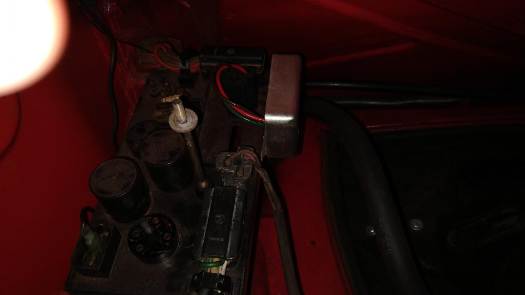
The D- signal can be found on the cable from the alternator. Below is my 914 showing the cable and its connector. You should be able to measure right on the connector with the VR left in place.
The VR I have was purchased at my local FLAPS and works very well. 14V all day.
Attached thumbnail(s)
Posted by: Spoke Sep 5 2019, 04:02 PM
This diagram shows which signals are which.
In this diagram, DF goes to DF, D- to D- and nothing else.
D+ goes to D+ then onto pin 2 of the 14 pin connector going to the cabin and to the GEN bulb.
Attached thumbnail(s)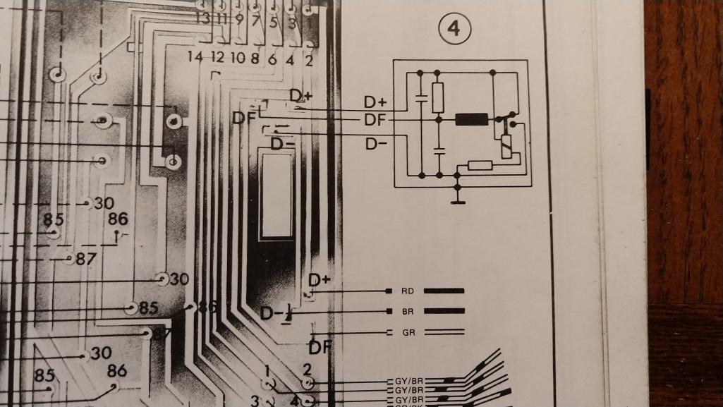
Posted by: Gatornapper Sep 5 2019, 04:54 PM
I should have told you all I don't have regular problems. If they are regular, I fix them, no one knows. The plot thickened a lot today. And in my view gets worse.
1. Received new SS VR from Rock Auto today, AC Delco, is like the European one.
a. Bad news: no change. 12.12 volts at battery with engine running
b. Good news: GEN light is now reflecting reality - it glows. Higher I rev engine,
more it glows. Light is very dim at idle tho. NO Gen light with original VR or
NOS one I had.
2. I completely refreshed main ground between chassis and tranny. No change.
3. Using a very unusual bronze ground connector used by electricians I securely attached a new #6 Cu. wire to the alternator case and connected the other end to the ground/negative on the battery. NO CHANGE. Bummer. I was hoping Zach's solution would work.
While I did not take voltage readings while engine was running (Spoke - DUH - of course I can probe generator cable connections - brain was not turned on.....), I did take readings with engine off. DF and D- had infinite resistance to ground. D+ had 74 ohms.
4. Just to make sure I wasn't dreaming, I again removed the VR and jumped D+ and DF, and once again, got between 16.8 and 17 volts at the battery. So alternator HAS to be good, correct?
Ok, now taking readings at alternator plug terminals while engine is running.
Hoping someone has some new insights.....
Thanks to all for laboring with me through this mystery.......
GN
Posted by: Spoke Sep 5 2019, 05:41 PM
It makes me wonder if the VR is not starting because of insufficient current though the GEN light. Try this test. Pull out the gauge with the GEN light. Start the engine. Carefully touch a screwdriver across the GEN bulb. This is to force the VR voltage to battery voltage. See if the alternator starts up. This shouldn't damage anything.
Don't touch the screwdriver to the case When doing this.
Posted by: Gatornapper Sep 5 2019, 06:05 PM
Spoke -
D- to engine or chassis with engine running, VR in place: .01v
Nothing. Zip. Nada. Zero. Barely measurable.
GN
Posted by: Gatornapper Sep 5 2019, 06:12 PM
Ok, I can do that, but then I need someone else at my DVM to read the voltage at the battery, right?
I personally doubt this is the problem - the light comes on at a correct brightness (seems to me) when ignition is on, engine off. It would only get dim with first 2 VR's, but now seems to work correctly with the new SS VR. This would indicate to me that its wattage is correct.
How much trouble to take gauge out? Don't you pull the whole instrument cluster? It's with the Temp Gauge........
Gotcha on not shorting anything......
I'm leaning toward a bad relay board. The GEN lamp and relay board are about all that's left, aren't they?
It makes me wonder if the VR is not starting because of insufficient current though the GEN light. Try this test. Pull out the gauge with the GEN light. Start the engine. Carefully touch a screwdriver across the GEN bulb. This is to force the VR voltage to battery voltage. See if the alternator starts up. This shouldn't damage anything.
Don't touch the screwdriver to the case When doing this.
Posted by: Gatornapper Sep 5 2019, 06:18 PM
I have another idea: I'll bring a 1 amp fused 12+ from the battery through an 1156 bulb to D+ on the alternator plug terminal. Or a smaller lamp.......
And just touch it to energize the armature.........
Whacha think?
GN
It makes me wonder if the VR is not starting because of insufficient current though the GEN light. Try this test. Pull out the gauge with the GEN light. Start the engine. Carefully touch a screwdriver across the GEN bulb. This is to force the VR voltage to battery voltage. See if the alternator starts up. This shouldn't damage anything.
Don't touch the screwdriver to the case When doing this.
Posted by: Spoke Sep 5 2019, 06:41 PM
I have another idea: I'll bring a 1 amp fused 12+ from the battery through an 1156 bulb to D+ on the alternator plug terminal. Or a smaller lamp.......
And just touch it to energize the armature.........
Whacha think?
What we're trying to do with the shorting the GEN bulb is to provide more energy to the VR and armature circuit to get the alternator to start. Once it starts, the GEN light should go out and the alternator will start working. So you don't need anyone to check with a DMM.
The 1156 bulb will work as well. That's basically what you're doing with shorting the GEN light. The GEN gauge pulls out of the dash by itself. Just like the tach and speedo will pull right out. Takes a little wiggling to pull it out. Sometimes the rubber gasket stays on the gauge and sometimes the rubber gasket stays on the dash.
The 1156 is a good idea. Just touch it from the battery to D+. This will provide a lot of current to the armature and should start up the alternator.
About the grounding, that you can get 17V on the battery when you short D+ to DF is a good indication that the ground is at least ok.
Posted by: Gatornapper Sep 5 2019, 07:05 PM
Spoke -
Ok, let's assume that jumping 12+ to the armature does activate the alternator, and it's charging. Now what?
Or, let's assume that jumping the 12+ does nothing - now what?
Wondering where we go from either one.....
TIA,
GN
What we're trying to do with the shorting the GEN bulb is to provide more energy to the VR and armature circuit to get the alternator to start. Once it starts, the GEN light should go out and the alternator will start working. So you don't need anyone to check with a DMM.
The 1156 bulb will work as well. That's basically what you're doing with shorting the GEN light. The GEN gauge pulls out of the dash by itself. Just like the tach and speedo will pull right out. Takes a little wiggling to pull it out. Sometimes the rubber gasket stays on the gauge and sometimes the rubber gasket stays on the dash.
The 1156 is a good idea. Just touch it from the battery to D+. This will provide a lot of current to the armature and should start up the alternator.
About the grounding, that you can get 17V on the battery when you short D+ to DF is a good indication that the ground is at least ok.
[/quote]
Posted by: Spoke Sep 5 2019, 07:29 PM
Spoke -
Ok, let's assume that jumping 12+ to the armature does activate the alternator, and it's charging. Now what?
Or, let's assume that jumping the 12+ does nothing - now what?
Wondering where we go from either one.....
TIA,
GN
At this point, we're just testing things to try and get the alternator/VR working.
Another new VR didn't do anything which means the VR is not the issue. Something else is and we need to uncover what that is.
Do the 1156 test and see what happens. If the alternator starts up and keeps running, then you know the alternator/VR can run.
Posted by: 914Sixer Sep 6 2019, 02:54 PM
Adding information from owners manual. Please read information. Your last VR has a problem.
Attached image(s)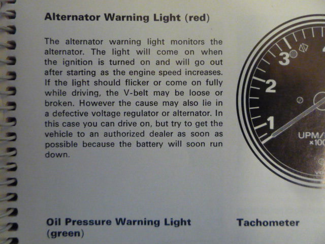
Posted by: Gatornapper Sep 6 2019, 03:34 PM
Mark - yes, I know this - so I have 3 bad VR's? 2 bad new ones in a row? One I got yesterday is SS too.......doubt it is bad.......
Belt is tight BTW.....
Understand and went through all this too.....except hitting DF with a full 12+v, which I'll do tonight......
https://www.pelicanparts.com/techarticles/914_alternator_troubleshoot/914_alternator_troubleshoot.htm
Thanks,
GN
Adding information from owners manual. Please read information. Your last VR has a problem.
Posted by: 914Sixer Sep 6 2019, 03:54 PM
I would say the Bosch ones are ok. Is the alternator harness the original?
Posted by: Spoke Sep 6 2019, 04:47 PM
I have another idea: I'll bring a 1 amp fused 12+ from the battery through an 1156 bulb to D+ on the alternator plug terminal.
About the 1156 bulb with 1A fuse; the 1156 bulb will be the fuse and the load. The 1A fuse isn't needed as the 1156 bulb when put across 12V will burn about 2A.
Waiting to see what happens with this test. This will see if the alternator/VR will start up with significantly more current via the 1156. If the alternator/VR does start up, then the 1156 bulb will go out. If the alternator/VR does not start up, then the 1156 bulb will continue to light.
Posted by: Gatornapper Sep 7 2019, 05:32 AM
I would say yes.
But remember, it puts out full voltage and more when D+ & DF are jumped - on that harness......if the harness were bad, I don't think you'd see that.
Somehow the armature is not getting excited.
GN
I would say the Bosch ones are ok. Is the alternator harness the original?
Posted by: Gatornapper Sep 7 2019, 05:46 AM
I have another idea: I'll bring a 1 amp fused 12+ from the battery through an 1156 bulb to D+ on the alternator plug terminal.
About the 1156 bulb with 1A fuse; the 1156 bulb will be the fuse and the load. The 1A fuse isn't needed as the 1156 bulb when put across 12V will burn about 2A. I thought of that myself after I suggested the setup - no need for 2 fuses....been very busy, will try tonight.....
Waiting to see what happens with this test. This will see if the alternator/VR will start up with significantly more current via the 1156. If the alternator/VR does start up, then the 1156 bulb will go out. If the alternator/VR does not start up, then the 1156 bulb will continue to light. Yup! Exactly. It will function as the GEN light......
Also doing this from Pelican's site: To trouble-shoot the problem, you need to check the various sections independently. Thus the first check: Connect +12 volts from the battery to the DF terminal on the relay board. This is the maximum field current situation, and should result in maximum output of the alternator. Note that this checks the B+ diodes, the alternator windings, and the common diodes. It does NOT check the D+ diodes.
But, essentially, this is duplicating the test with the 1156, and just energizing the armature from another route - directly on the DF wire instead of through the switch in the VR......
GN
Posted by: Gatornapper Sep 7 2019, 07:15 PM
Post I just made on Pelican's forum:
Greg -
Did your test. Plugged VR directly into alternator harness. Hit D+ with other side of lamp with 12+ on the opposite side. Lamp lit up - just like dash light - as it took the place of the dash GEN light in the circuit. Still no charging. 12.2 v at battery.
So clearly something is wrong, and it's not in the relay board or dash light circuit.
AND YET, using the 2 tests in this Pelican article,
https://www.pelicanparts.com/techarticles/914_alternator_troubleshoot/914_alternator_troubleshoot.htm
The alternator checks out fine.
Test 1 "checks the B+ diodes, the alternator windings, and the common diodes. It does NOT test the D+ diodes". I hit DF with 12+ volts, and the system charged at full normal voltage: 14.1 volts.
But as soon as I removed the 12+ v from DF, the charging ceased. Once the armature is energized, shouldn't it stay energized?
Test 2, we know, tests the D+ diodes and "D+ portion of the system", by jumping D+ and DF - my system also passed this, producing 17+ v at the battery.
So what part of the system is failing? I can't see how it is the harness - as in both tests 1 and 2 full charging voltage is being produced at the battery....using the existing harness.
Seems to me the problem is indeed inside the alternator - as it will not retain its charge on the armature once charged. Something is preventing the armature from retaining its charge......all other things seem working properly.
Any insight and wisdom is greatly appreciated.
GN
Posted by: ClayPerrine Sep 7 2019, 07:20 PM
You can't use just any light for the alternator light. It has to be a particular bulb to make the circuit work.
If you can connect DF to the positive battery post with the engine running, and get 17+ volts, then the alternator and harness is good. I would change the voltage regulator. Get a Bosch regulator, not some aftermarked reproduction.
Posted by: Gatornapper Sep 7 2019, 07:53 PM
Clay -
The 2nd VR I tried is NOS I got from a reliable forum member. It didn't work.
I only got the aftermarket one because it didn't work.
So you think I should buy a 2nd Bosch VR, only a modern one? How much are they? About $200, right?
Cannot see why the new SS VR I just got shouldn't work......
Pretty sure my GEN bulb is original, but will check it tomorrow - know it has to be 2 watt.
Thanks,
GN
You can't use just any light for the alternator light. It has to be a particular bulb to make the circuit work.
If you can connect DF to the positive battery post with the engine running, and get 17+ volts, then the alternator and harness is good. I would change the voltage regulator. Get a Bosch regulator, not some aftermarked reproduction.
Posted by: Gatornapper Sep 8 2019, 05:54 AM
Clay -
The strong implication of this statement in the Pelican article, "Too low a wattage bulb will not supply enough field current for "bootstrap" operation to be reliable. The Bosch book that I have states that the lamps must be at least 2 watts for 12 volt systems.", is that a higher wattage bulb, like I used in my test, should be no problem.
The problem is with a lower wattage bulb.
GN
You can't use just any light for the alternator light. It has to be a particular bulb to make the circuit work.
If you can connect DF to the positive battery post with the engine running, and get 17+ volts, then the alternator and harness is good. I would change the voltage regulator. Get a Bosch regulator, not some aftermarked reproduction.
Posted by: Spoke Sep 8 2019, 09:41 AM
Did you do the test with the 1156 bulb across the GEN light or across battery to D+? If so, what happened?
Posted by: Gatornapper Sep 8 2019, 11:24 AM
Yes. Nothing happened. Did not energize the armature, no charging, light went on and stayed on - just like GEN light......
As wattage of bulb was more than 2 watts, the filament being a lower resistance, the voltage hitting the armature would have been higher than that of the 2 watt Gen bulb - and the armature should have been excited and produced a charge.
HOWEVER, remember - when I hit DF with a full 12 volts - the system charges to a full 14.1 volts as it should........but as soon as you remove the external 12v to DF, the charging ceases. Once energized, the armature should stay excited, producing a charge.
So I'm thinking the problem is in the armature.....perhaps a break in insulation that allows leakage of the voltage. I.e., a short.
GN
Did you do the test with the 1156 bulb across the GEN light or across battery to D+? If so, what happened?
Posted by: Spoke Sep 8 2019, 04:45 PM
Yes. Nothing happened. Did not energize the armature, no charging, light went on and stayed on - just like GEN light......
OK, so a higher power GEN light doesn't get the VR started...
As wattage of bulb was more than 2 watts, the filament being a lower resistance, the voltage hitting the armature would have been higher than that of the 2 watt Gen bulb - and the armature should have been excited and produced a charge.
You applied the 1156 from 12V battery to D+, not to DF. DF energized is the responsibility of the VR. If the VR is not working, applying 12V to D+ will not energize DF.
HOWEVER, remember - when I hit DF with a full 12 volts - the system charges to a full 14.1 volts as it should........but as soon as you remove the external 12v to DF, the charging ceases. Once energized, the armature should stay excited, producing a charge.
Did you do this with the VR in place? Once you remove 12V from DF, if the VR is not operating, the voltage at DF could go to zero and the alternator will not function.
So I'm thinking the problem is in the armature.....perhaps a break in insulation that allows leakage of the voltage. I.e., a short.
GN
Your previous test seems in conflict with a bad armature as you were able to get 17V at the battery with the armature initially being driven with the GEN light:
DID THE D+ TO DF Jumper TEST: at rpm, voltage at battery jumps to 16.9 to over 17.
It still seems like the VR is not starting up. I would be curious to know the voltages at the VR when running. The VR I have on my 914 has a plug and wires connecting to the VR thus I can measure voltages right on the VR plug. They should be the same as the voltages on the alternator plug.
Here's another test: With VR in place, start engine then short DF to D+ with the 1156 bulb. What you'd be doing is simulating the VR pulling up on DF as it should but seems it isn't. If the battery voltage goes up, then the alternator should be good.
Posted by: Gatornapper Sep 8 2019, 06:17 PM
Yes. Nothing happened. Did not energize the armature, no charging, light went on and stayed on - just like GEN light......
OK, so a higher power GEN light doesn't get the VR started...Correct.
As wattage of bulb was more than 2 watts, the filament being a lower resistance, the voltage hitting the armature would have been higher than that of the 2 watt Gen bulb - and the armature should have been excited and produced a charge.
You applied the 1156 from 12V battery to D+, not to DF. YES. DF energized is the responsibility of the VR. If the VR is not working, applying 12V to D+ will not energize DF.
HOWEVER, remember - when I hit DF with a full 12 volts - the system charges to a full 14.1 volts as it should........but as soon as you remove the external 12v to DF, the charging ceases. Once energized, the armature should stay excited, producing a charge.
Did you do this with the VR in place? YES. Once you remove 12V from DF, if the VR is not operating, the voltage at DF could go to zero and the alternator will not function.3 VR's, 2 which are new, this occurred.
So I'm thinking the problem is in the armature.....perhaps a break in insulation that allows leakage of the voltage. I.e., a short.
GN
Your previous test seems in conflict with a bad armature as you were able to get 17V at the battery with the armature initially being driven with the GEN light: I agree - just stabbing in the dark for what's going on.....
DID THE D+ TO DF Jumper TEST: at rpm, voltage at battery jumps to 16.9 to over 17.
It still seems like the VR is not starting up. I would be curious to know the voltages at the VR when running. The VR I have on my 914 has a plug and wires connecting to the VR thus I can measure voltages right on the VR plug. They should be the same as the voltages on the alternator plug. I read zero resistance between each point of D+, DF, and D- between the VR pins and the alternator harness pins.
Read voltage from each point to ground? Will do.
Here's another test: With VR in place, start engine then short DF to D+ with the 1156 bulb. What you'd be doing is simulating the VR pulling up on DF as it should but seems it isn't. If the battery voltage goes up, then the alternator should be good.
What is strange to me is that once armature is excited/energized, it won't stay energized - or so it seems. This should not be. As the voltage across the GEN lamp is zero with a working VR and alternator once system is running, the initial exciting of the armature is enough. Correct?
Spoke - thanks for hanging with me on this. Thanks for the patience. Very frustrating for me - fixing electrical problems is my strong suite, and this is the first time ever I haven't found what is wrong and corrected it in my long life. I think there is something here about this system I am not seeing. But in actuality, the circuitry is very simple - as you well know.
Posted by: euro911 Sep 8 2019, 07:25 PM
At this point I'm suspecting one of the alternator diodes has gone bad.
I'd cut to the chase and try another alternator. Maybe another local member has a (known good) spare that you can try & buy
Posted by: Gatornapper Sep 8 2019, 07:33 PM
Mark -
Totally understand - but if one of the diodes were bad, I don't see how the alternator could put out a full 17+ volts on the test jumping D+ and DF, which my alternator did.
Unit also put out full 14.1v on other diode test......
I think something else is going on. Some think only the $200 Bosch VR will fix things.
Don't know anyone with an good alternator. If I have to pull it, pretty sure I can rebuild it myself.
Thanks,
GN
At this point I'm suspecting one of the alternator diodes has gone bad.
I'd cut to the chase and try another alternator. Maybe another local member has a (known good) spare that you can try & buy
Posted by: Spoke Sep 8 2019, 08:58 PM
At this point I'm suspecting one of the alternator diodes has gone bad.
I'd cut to the chase and try another alternator. Maybe another local member has a (known good) spare that you can try & buy
An easy way to test for burned diodes is to remove the VR and short DF to D+.
The alternator will produce maximum output.
At this point if all diodes are good, the battery voltage to chassis should equal the D+ voltage to chassis.
Posted by: VaccaRabite Sep 9 2019, 11:06 AM
At this point I'm suspecting one of the alternator diodes has gone bad.
I'd cut to the chase and try another alternator. Maybe another local member has a (known good) spare that you can try & buy
An easy way to test for burned diodes is to remove the VR and short DF to D+.
The alternator will produce maximum output.
At this point if all diodes are good, the battery voltage to chassis should equal the D+ voltage to chassis.

You need to know if the alternator is doing anything.
You will know immediately once DF is shorted to D+. The engine will suddenly have the full load of the alternator dragging on it and RPMs will drop. Using your meter should show 16-18 volts at idle this way. Don't do this longer then needed though, as you will be overcharging your battery.
Zach
Posted by: Gatornapper Sep 9 2019, 07:26 PM
Memories guys? Jerry & Zack - Long ago I jumped D+ & DF and did get full 17v at the battery and reported on that numerous times to support my view that the alternator is fine. Even ran the test multiple times.
Also put 12+v to DF as the Pelican article suggests to check all the other diodes, and it too produced a full 14.1 v at the battery, showing all the other alternator diodes are good.
Today verified that the GEN light is indeed 2 watts - and just for the fun of it installed a new 2 watt lamp.
No change.
Thanks,
GN
At this point I'm suspecting one of the alternator diodes has gone bad.
I'd cut to the chase and try another alternator. Maybe another local member has a (known good) spare that you can try & buy
An easy way to test for burned diodes is to remove the VR and short DF to D+.
The alternator will produce maximum output.
At this point if all diodes are good, the battery voltage to chassis should equal the D+ voltage to chassis.
Posted by: Spoke Sep 9 2019, 10:50 PM
...I jumped D+ & DF and did get full 17v at the battery...
I would like you to repeat this test and measure:
1) Battery voltage to chassis
2) D+ voltage to chassis
3) GEN light goes out
We're looking to see that VBAT and D+ are exactly the same. This would verify that the diodes in the VBAT path and D+ path are functioning.
If VBAT not equal to D+, then diodes in the alternator may be suspect. The GEN light might be lit as well if VBAT != D+.
If VBAT == D+ AND GEN light goes out, then likely the alternator is ok. This also means that the GEN light provides enough current excite the armature and to bootstrap the alternator into functionality.
If the alternator passes this test, then we suspect the VR AND/OR the wiring to/from the VR. Generating a voltage at DF to excite the alternator is the responsibility of the VR. Thus my request to measure the voltages D+, DF, and D- to chassis directly at the VR connector. If D+ is less than 13-14V, then the VR should raise the voltage at DF to further excite the alternator to produce voltage/current.
No voltage at the DF pin on the alternator connector with D+ less than 14V and D- around zero volts points to the VR and its wiring.
Posted by: Spoke Sep 9 2019, 11:52 PM
Here's a way to do a quick test on the VR. I just did this on my 914. The goal is to see if the VR will raise the voltage at DF.
There are 2 parts to this test. This is part 1; Isolation of the VR.
The set up for test 1 is as follows:
1) Remove the connector to the alternator. This will remove the load on DF and isolate the VR. This also removed the ground connection to the VR which will be reconnected in step 4.
2) Remove the power to the FI ECU (if you have FI). If you have carbs, remove the ground jumper from the FI connector on the relay board. This jumper powers the fuel pump. We want the fuel pump off.
3) Remove the 12V connector to the ignition coil. This keeps the points/Pertronix/electronic points from being powered. If you have some other electronic ignition system, remove 12V power from the unit.
4) Ground the D- pin at the alternator connector on the relay board. When you disconnect the alternator plug, the VR loses its ground. I used the jumper wire from the FI ECU connector for the fuel pump to ground D- as shown below.
5) Turn the ignition key to ON.
6) Observe that the GEN light is OFF.
7) At the alternator socket on the relay board, measure D+ to chassis and DF to chassis. On my car, I measured about 10.5V at both D+ and DF.
8) Turn the ignition key to OFF.
Notes:
At step 7, the VR on my 914 sensed only 10.5V and attempted to drive the armature via DF to a high voltage.
The resting voltage of the battery on my car was 12V. This seems low although all exterior marker lights (LEDs) were on as I've rewired the lights to come on when the ignition is ON.
Attached thumbnail(s)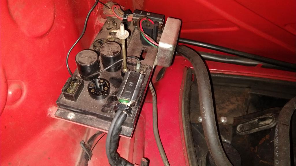
Posted by: Spoke Sep 10 2019, 12:04 AM
Part 2 of the VR test is to check the D+ and DF voltages with the alternator connected to the VR.
The set up for test 2 is as follows:
1) If test 1 was just run, all wires are connected as needed. If test 1 was not run, do steps 1 through 4.
2) Remove the ground jumper on the D- pin at the alternator connector on the relay board.
3) Connect the alternator cable to the alternator connector on the relay board. Now the alternator/VR are connected as in the running condition.
4) Turn the ignition key to ON, do not start the car.
5) Observe the GEN light on brightly.
6) At the alternator socket on the relay board, measure D+ to chassis and DF to chassis. On my car, I measured about 2.3V at D+ and 1.5V at DF.
7) The test is done. Reconnect the FI ECU or fuel pump connections. Reconnect the ignition wires to the coil.
Notes:
On my 914, very little voltage was present at D+ and DF since most of the voltage was dropped across the GEN light. Even with only 2.3V at D+, the VR still raised the voltage DF to 1.5V.
Once spinning when starting the car and initial engine running, this little voltage to DF should be enough for the alternator to generate at least a few more volts at D+ which will drive the DF (armature) even higher in voltage thus producing more voltage until the alternator/VR reaches 13-14V and the system is now in regulation.
Posted by: Gatornapper Sep 10 2019, 07:21 AM
Ok, will do today.
One additional bit of info: GEN light is OUT when engine is idling.....only comes on with rpm increase, more rpm = brighter GEN light. Bat to chassis when light is OUT is about 12.2 on a fully-charged 12.6 v resting battery.
GN
...I jumped D+ & DF and did get full 17v at the battery...
I would like you to repeat this test and measure:
1) Battery voltage to chassis
2) D+ voltage to chassis
3) GEN light goes out
We're looking to see that VBAT and D+ are exactly the same. This would verify that the diodes in the VBAT path and D+ path are functioning.
If VBAT not equal to D+, then diodes in the alternator may be suspect. The GEN light might be lit as well if VBAT != D+.
If VBAT == D+ AND GEN light goes out, then likely the alternator is ok. This also means that the GEN light provides enough current excite the armature and to bootstrap the alternator into functionality.
If the alternator passes this test, then we suspect the VR AND/OR the wiring to/from the VR. Generating a voltage at DF to excite the alternator is the responsibility of the VR. Thus my request to measure the voltages D+, DF, and D- to chassis directly at the VR connector. If D+ is less than 13-14V, then the VR should raise the voltage at DF to further excite the alternator to produce voltage/current.
No voltage at the DF pin on the alternator connector with D+ less than 14V and D- around zero volts points to the VR and its wiring.
Posted by: Gatornapper Sep 10 2019, 07:37 AM
What is this jumper in the lower left corner of my relay board?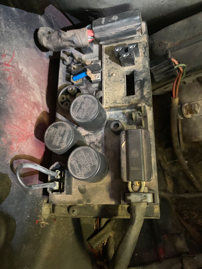
Posted by: ClayPerrine Sep 10 2019, 07:42 AM
What is this jumper in the lower left corner of my relay board?
That would jump the starter circuit to the fuel pump relay output. It doesn't make sense to be there.
Maybe you have a relay board issue? Did you try another one?
Posted by: Gatornapper Sep 10 2019, 07:42 AM
Spoke -
Do not know where/what this is - car is carbureted:
2) Remove the power to the FI ECU (if you have FI). If you have carbs, remove the ground jumper from the FI connector on the relay board. This jumper powers the fuel pump. We want the fuel pump off.
Posted by: Gatornapper Sep 10 2019, 08:12 AM
Clay -
Another relay board is being loaned to me and should be here tomorrow.
Should I remove this jumper? No idea why it is there, relay board looks original to car.....
If I remove it, will fuel pump relay still be energized by ignition key ON?
Thanks,
GN
That would jump the starter circuit to the fuel pump relay output. It doesn't make sense to be there.
Maybe you have a relay board issue? Did you try another one?
Posted by: Spoke Sep 10 2019, 08:25 AM
Spoke -
Do not know where/what this is - car is carbureted:
2) Remove the power to the FI ECU (if you have FI). If you have carbs, remove the ground jumper from the FI connector on the relay board. This jumper powers the fuel pump. We want the fuel pump off.
The way that jumper is installed, the FP will not run while you crank the engine. When you release the starter, the FP relay is energized through the starter and runs normally.
The front left pin should be connected to ground. This happens in your car when you release the starter.
Posted by: ClayPerrine Sep 10 2019, 08:27 AM
Clay -
Another relay board is being loaned to me and should be here tomorrow.
Should I remove this jumper? No idea why it is there, relay board looks original to car.....
If I remove it, will fuel pump relay still be energized by ignition key ON?
Thanks,
GN
That would jump the starter circuit to the fuel pump relay output. It doesn't make sense to be there.
Maybe you have a relay board issue? Did you try another one?
That jumper hooks the yellow wire for the starter to the output side of the fuel pump relay. It would not power the fuel pump when the car is running.
Like I said, it doesn't make any sense to be there. Without something to energize the ECU relay, the fuel pump relay won't turn on.
It is possible that someone moved the pins around in the harness connectors to the relay board. I would take a long wire, and hook it to the rearmost pin on the relay board where the jumper is. Then touch the other end to the positive battery post. The engine should crank if everything is wired correctly.
Posted by: Spoke Sep 10 2019, 08:42 AM
Ok, will do today.
One additional bit of info: GEN light is OUT when engine is idling.....only comes on with rpm increase, more rpm = brighter GEN light. Bat to chassis when light is OUT is about 12.2 on a fully-charged 12.6 v resting battery.
GN
That the GEN light goes out means the D+ voltage is equal to or near the Bat voltage. In the test that I detailed with the alternator yesterday, the GEN light was out on my car with the alternator unplugged from the relay board even though the VR was in the circuit.
In the run that you describe above, does the GEN light come on with key ON and engine not running?
In the run you describe, with more RPM the GEN light is brighter. It would be interesting to know what the battery voltage is as well as the D+ voltage. They are different but not sure which one is greater than the other.
Posted by: Spoke Sep 10 2019, 09:17 AM
Clay -
Another relay board is being loaned to me and should be here tomorrow.
Should I remove this jumper? No idea why it is there, relay board looks original to car.....
If I remove it, will fuel pump relay still be energized by ignition key ON?
Thanks,
GN
That would jump the starter circuit to the fuel pump relay output. It doesn't make sense to be there.
Maybe you have a relay board issue? Did you try another one?
That jumper hooks the yellow wire for the starter to the output side of the fuel pump relay. It would not power the fuel pump when the car is running.
Like I said, it doesn't make any sense to be there. Without something to energize the ECU relay, the fuel pump relay won't turn on.
It is possible that someone moved the pins around in the harness connectors to the relay board. I would take a long wire, and hook it to the rearmost pin on the relay board where the jumper is. Then touch the other end to the positive battery post. The engine should crank if everything is wired correctly.
The jump powers the FP relay any time the key is in the ON position. In the start position, the FP will not run.
Posted by: ClayPerrine Sep 10 2019, 12:05 PM
The jump powers the FP relay any time the key is in the ON position. In the start position, the FP will not run.
Per the wiring diagram and lots of years of experience, it won't work that way. If it does, then something has been altered in the wiring or the relay board.
Posted by: Spoke Sep 10 2019, 12:49 PM
The jump powers the FP relay any time the key is in the ON position. In the start position, the FP will not run.
Per the wiring diagram and lots of years of experience, it won't work that way. If it does, then something has been altered in the wiring or the relay board.
Yeah that jumper connection threw me for a loop too. I didn't think it work work and maybe something was re-wired from the OEM wiring.
However looking at the wire diagram below shows the path to ground for the fuel pump relay coil going through the starter bendix. When the starter is energized the FP turns off. When the key is ON, the FP will run. Not ideal but still operational. It would be best to remove that connection and just ground pin III of the FI connector.
Attached thumbnail(s)
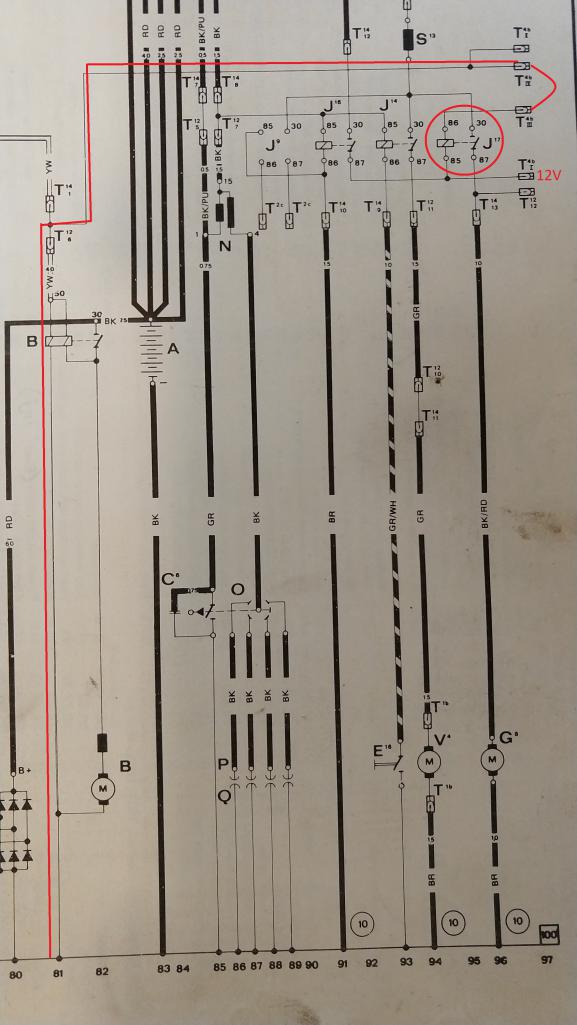
Posted by: lierofox Sep 10 2019, 01:12 PM
The jump powers the FP relay any time the key is in the ON position. In the start position, the FP will not run.
Per the wiring diagram and lots of years of experience, it won't work that way. If it does, then something has been altered in the wiring or the relay board.
From the relay board wiring diagram I have, it looks like Spoke's right.
Terminal III (top left) goes to the ground terminal on the fuel pump relay, the positive terminal of that relay is fed by the Power Supply relay.
Terminal II and IV (bottom 2) goes directly to the yellow starter wire.
With that configuration, yeah, the only way the relay would find ground is through the starter solenoid when it's NOT energized.
Posted by: ClayPerrine Sep 10 2019, 04:36 PM
The jump powers the FP relay any time the key is in the ON position. In the start position, the FP will not run.
Per the wiring diagram and lots of years of experience, it won't work that way. If it does, then something has been altered in the wiring or the relay board.
From the relay board wiring diagram I have, it looks like Spoke's right.
Terminal III (top left) goes to the ground terminal on the fuel pump relay, the positive terminal of that relay is fed by the Power Supply relay.
Terminal II and IV (bottom 2) goes directly to the yellow starter wire.
With that configuration, yeah, the only way the relay would find ground is through the starter solenoid when it's NOT energized.
That is not a good way to do it. Very Redneck.
Posted by: Gatornapper Sep 10 2019, 07:15 PM
NEVER have any problem starting this engine - is the easiest starting engine of any machine/vehicle I've ever owned - it always starts on the firing of the very first piston - or so it seems.
It does sometimes die after starting tho, and I have to switch the key back to "Off" to engage the starter a 2nd time.
Hard for me to believe the fuel pump isn't pumping when I crank this engine because while it idles terribly, it starts every time. It's never been a problem. Never.
The way that jumper is installed, the FP will not run while you crank the engine. When you release the starter, the FP relay is energized through the starter and runs normally.
The front left pin should be connected to ground. This happens in your car when you release the starter.
Posted by: Gatornapper Sep 10 2019, 07:22 PM
The GEN light is on bright when ignition is ON, engine NOT running - as it should be.
Funny that while I rev the engine up and down, the GEN light goes from Dim/off at idle to bright a 2,000 rpm - while the battery voltage remains fairly constant at 12.2 +/-.
I have not checked the D+ voltage in this scenario - will tomorrow.
Thanks,
GN
Ok, will do today.
One additional bit of info: GEN light is OUT when engine is idling.....only comes on with rpm increase, more rpm = brighter GEN light. Bat to chassis when light is OUT is about 12.2 on a fully-charged 12.6 v resting battery.
GN
That the GEN light goes out means the D+ voltage is equal to or near the Bat voltage. In the test that I detailed with the alternator yesterday, the GEN light was out on my car with the alternator unplugged from the relay board even though the VR was in the circuit.
In the run that you describe above, does the GEN light come on with key ON and engine not running?
In the run you describe, with more RPM the GEN light is brighter. It would be interesting to know what the battery voltage is as well as the D+ voltage. They are different but not sure which one is greater than the other.
Posted by: VaccaRabite Sep 10 2019, 07:24 PM
Memories guys? Jerry & Zack - Long ago I jumped D+ & DF and did get full 17v at the battery and reported on that numerous times to support my view that the alternator is fine. Even ran the test multiple times.
Also put 12+v to DF as the Pelican article suggests to check all the other diodes, and it too produced a full 14.1 v at the battery, showing all the other alternator diodes are good.
I don't usually remember what I had for lunch, let alone what happened 100 posts ago.

Electrical problems suck! When I was banging my head against the wall over my alternator problems I wanted to just beam Jerry over to my garage. the theory goes over my head really quick.
Zach
Posted by: euro911 Sep 10 2019, 07:31 PM
I was told to install that jumper for the fuel pump by a few highly respected/knowledgeable on this board ... (for a carbureted motor)
Posted by: Gatornapper Sep 10 2019, 07:35 PM
Clay -
Just to make sure I don't short something out, you mean Pin III, correct?
Think I'll fuse the jumper from 12+ just to be safe.
From all you all are saying, this jumper doesn't make any sense. I get that.
But I can almost certainly assure you that the FP is running while I crank the engine. If it didn't, it seems to me I'd have a lot of dry cranking from time to time.
While this engine has poor compression and doesn't idle, it's the best starting engine I've ever seen. It seems like 1 revolution and she's running - every time.
GN
Posted by: Gatornapper Sep 10 2019, 07:52 PM
Mark -
The first comforting thing I've heard about that jumper - as the Porsche dealer did the carb conversion, the jumper definitely doesn't look like a shade-tree mechanic one, but a very professional one. Note the extra insulation from the terminals back an inch or so....almost like it's a factory jumper....or commercial one.
Some modification would be necessary for fuel pump energizing when eliminating the ECU - as it controlled the fuel pump. So this totally makes sense......
GN
I was told to install that jumper for the fuel pump by a few highly respected/knowledgeable on this board ... (for a carbureted motor)
Posted by: Spoke Sep 10 2019, 08:30 PM
I was told to install that jumper for the fuel pump by a few highly respected/knowledgeable on this board ... (for a carbureted motor)
This connection has been socialized many times and succinctly documented by SirAndy in this thread:
http://www.914world.com/bbs2/index.php?showtopic=25954
The fuel pump relay coil is grounded as shown by SirAndy in this picture. What was done on Gatornapper's car is quite unique and not ideal but does work. On his list of things to do on his 914 is correcting this connection.
Attached image(s)
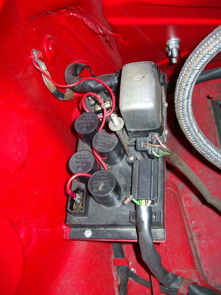
Posted by: Spoke Sep 10 2019, 08:34 PM
I don't usually remember what I had for lunch, let alone what happened 100 posts ago.
Zach
I concur.
Although not yet legally in PA... 

Posted by: Spoke Sep 10 2019, 08:47 PM
Mark -
The first comforting thing I've heard about that jumper - as the Porsche dealer did the carb conversion, the jumper definitely doesn't look like a shade-tree mechanic one, but a very professional one....
The jumper is well done and quite unique. The jumper on your 914 definitely stumped the band although it does work. SirAndy's solution is the one you want.
Put it on your list of things to correct. It is not as important as getting the alternator/VR working.
Posted by: GregAmy Sep 11 2019, 05:28 AM
Post #23 (on page 2 of now 7):
Post #36 (also on page 2 of now 7):
Quick follow up: alternator replacement solved it. I'm guessing a bad diode.
That's such a hateful job...
Replace the alternator.
Edit: print these out in color, and keep them in your manual. As an electrical professional, you can appreciate their value. I've got mine spliced together in a multi-fold so I can expand them out on the toolbox and work through any/all electrical issues...
http://web.archive.org/web/20140328013841/https://www.pelicanparts.com/914/914_electrical_diagrams.htm
Posted by: Gatornapper Sep 11 2019, 08:30 AM
Thanks Greg....started doing so on many of the comments here many schematics from the start. Thanks also for the list at Pelican - I've got a lot of their diagrams, but not the list you sent.
Trying $200 Bosche VR and working relay board tonight/tomorrow. If they do not correct things, will rebuild alternator or have it rebuilt. Like you, I suspect they will change nothing.
If the alternator is bad, I want a technical explanation for why it passes all the tests except for the one that counts - working.
Just don't want to rebuild alternator and discover I still have the same problem......since no one can explain why I'm getting these results, I see that as a possibility - one I do not like at all.
GN
Post #23 (on page 2 of now 7):
Post #36 (also on page 2 of now 7):
Quick follow up: alternator replacement solved it. I'm guessing a bad diode.
That's such a hateful job...
Replace the alternator.
Edit: print these out in color, and keep them in your manual. As an electrical professional, you can appreciate their value. I've got mine spliced together in a multi-fold so I can expand them out on the toolbox and work through any/all electrical issues...
http://web.archive.org/web/20140328013841/https://www.pelicanparts.com/914/914_electrical_diagrams.htm
Posted by: Gatornapper Sep 11 2019, 08:33 AM
Mark -
The first comforting thing I've heard about that jumper - as the Porsche dealer did the carb conversion, the jumper definitely doesn't look like a shade-tree mechanic one, but a very professional one....
The jumper is well done and quite unique. The jumper on your 914 definitely stumped the band although it does work. SirAndy's solution is the one you want.
Put it on your list of things to correct. It is not as important as getting the alternator/VR working. WILL DO!
Posted by: GregAmy Sep 11 2019, 08:53 AM
No one on this forum can provide that information to you.
A local rebuilder might...if you'd take the time to remove the alternator and bring it to them.
Posted by: Gatornapper Sep 11 2019, 10:51 AM
I understand that Greg. And I've been thinking of going to rebuilder soon to ask that very question......before I remove the alternator.......
No one on this forum can provide that information to you.
A local rebuilder might...if you'd take the time to remove the alternator and bring it to them.
Posted by: Spoke Sep 11 2019, 12:34 PM
I can understand questioning the health of the alternator in this situation.
However the simple DF to D+ test has the alternator producing 17V at the battery as expected for a good alternator.
An additional test with DF == D+ is to measure the voltage at D+. This should be equal to the battery voltage. This will go towards verifying the diodes are ok in the D+ as well as Battery outputs.
What is unexplained is why the VR produces no voltage at DF with the battery voltage at 12.x volts. The VR should be driving DF significantly if the battery voltage is in the 12.5V range.
Posted by: Gatornapper Sep 11 2019, 02:42 PM
Spoke -
May have found the problem, and it is indeed in the alternator.
Met this afternoon with the best mechanic I know in central VA.
The key is what I mentioned at least twice earlier - why, when I hit DF with 12+v and get a full charge at the battery, does the charge quit when I remove the 12v?????
Once charged, the armature should retain its charge - mine does not. For some reason, the armature loses its magnetism - when it should retain it once charged.
My mechanic friend said he has seen this on other bad alternators many times - but no one has ever explained to him WHY it occurs. It renders the alternator bad - even though all the diodes are fully functional.
So I suspect that is what I am dealing with.
GN
I can understand questioning the health of the alternator in this situation.
However the simple DF to D+ test has the alternator producing 17V at the battery as expected for a good alternator.
An additional test with DF == D+ is to measure the voltage at D+. This should be equal to the battery voltage. This will go towards verifying the diodes are ok in the D+ as well as Battery outputs.
What is unexplained is why the VR produces no voltage at DF with the battery voltage at 12.x volts. The VR should be driving DF significantly if the battery voltage is in the 12.5V range.
Posted by: Spoke Sep 11 2019, 04:05 PM
Spoke -
May have found the problem, and it is indeed in the alternator.
Met this afternoon with the best mechanic I know in central VA.
The key is what I mentioned at least twice earlier - why, when I hit DF with 12+v and get a full charge at the battery, does the charge quit when I remove the 12v?????
Once charged, the armature should retain its charge - mine does not. For some reason, the armature loses its magnetism - when it should retain it once charged.
My mechanic friend said he has seen this on other bad alternators many times - but no one has ever explained to him WHY it occurs. It renders the alternator bad - even though all the diodes are fully functional.
So I suspect that is what I am dealing with.
GN
About applying D+ to DF through the GEN light and getting 17V at the battery, then no output from the alternator when the D+ to DF connection is removed.
The alternator turning off when DF is disconnected from D+ (ie, interrupting the field current) is what one would expect if the VR is not in place or not functional. The alternator's output is somewhat proportional to the amount of field current and the rotational speed of the alternator. Take away the field current and the alternator stops.
There are lots of confusing data points with your charging systems for sure. I try to avoid swapping components w/o knowing exactly what is wrong. Especially the alternator which is not fun to remove.
There are 2 data points which are consistent with each other:
1) The alternator is not working (duh)
2) The VR is not producing voltage at DF
At this point I would be concerned with why the VR is not driving DF. I detailed a static test with engine not running to check the VR operation.
Posted by: Spoke Sep 11 2019, 04:07 PM
Here's a good description of an automotive charging system like the 914. Text and link provided.
https://www.americanautowire.com/view-faq/the-workings-of-an-alternator/
ALTERNATOR WARNING LIGHT
What does the little red light that says ALT, GEN or sometimes CHARGING mean when it comes on? Without being scientific, it means that either the alternator output voltage is lower than the battery voltage, or the battery voltage is lower than the alternator output voltage. If the light gets dimmer as you rev the engine up, then you most likely have a problem with the alternator. If the light gets brighter, then the battery is most likely the problem.
ALTERNATOR ROTOR
The rotor consists of a coil of wire wrapped around an iron core. Current through the wire coil – called “field” current – produces a magnetic field around the core. The strength of the field current determines the strength of the magnetic field. The field current is D/C, or direct current. In other words, the current flows in one direction only, and is supplied to the wire coil by a set of brushes and slip rings. The magnetic field produced has, as any magnet, a north and a south pole. The rotor is driven by the alternator pulley.
STATOR
Surrounding the rotor is another set of coils, three in total, called the stator. The stator is fixed to the shell of the alternator, and does not turn. As the rotor turns within the stator windings, the magnetic field of the rotor sweeps through the stator windings, producing an electrical current in the windings. Because of the rotation of the rotor, an alternating current is produced.
OUTPUT DIODES
A/C voltage is of little use in a D/C system, such as used in an automobile, so it has to be converted to D/C before it can be used. This conversion to D/C takes place in the “output diodes” and in the “diode trio.” Diodes have the property of allowing current to flow in only one direction, while blocking current flow in the other direction. The output diodes consist of six diodes, one pair for each winding. One of the pair is for the negative half cycle, and the other for the positive half cycle.
DIODE TRIO
The diode trio consists of three diodes, one per phase, which provides field current to the alternator regulator. This output will be discussed in more detail later in the “field current supply” section.
FIELD CURRENT SUPPLY
Field current supply is provided from two different sources – from the alternator itself, via the diode trio, and from the battery, via the alternator warning lamp. When you turn the key to “on”, the engine is not running and the alternator is not spinning. At this time, the voltage/current source for the field current is from the battery, through the ignition switch, and through the warning lamp. After the engine is started, and the alternator is up to speed, the output of the diode trio is fed back to the regulator, and serves as a source of current for the field current. At this time, the alternator is self sustaining, and the battery is no longer needed to power the automobiles electrical system.
REGULATOR
The regulator has two inputs and one output. The inputs are the field current supply and the control voltage input, and the output is the field current to the rotor. The regulator uses the control voltage input to control the amount of field current input that is allow to pass through to the rotor winding. If the battery voltage drops, the regulator senses this, by means of the connection to the battery, and allows more of the field current input to reach the rotor, which increases the magnetic field strength, which ultimately increases the voltage output of the alternator. Conversely, if the battery voltage goes up, less field current goes through the rotor windings, and the output voltage is reduced.
WARNING LIGHT
The alternator warning lamp travels a path to ground from the field current supply input to the voltage regulator. As a result, when the key is turned on, current flows through the warning lamp, through the resisters, transistors, and field coil in the alternator, and then to ground, causing the lamp to illuminate. Once the alternator is at full output its voltage will equal the battery voltage. At this time, with 12 volts on both sides, the lamp is out. If the alternator should fail, voltage from the diode trio would drop, and once again the lamp would light from the battery voltage. If the alternator output is only a little low, the lamp will be dimly lit. If the alternator fails completely, and the output voltage goes to zero, the lamp will be lit at full brilliance. Conversely, if the battery should fail, and the battery voltage drops, with the output voltage of the alternator on one side and the low battery voltage on the other, the lamp will also light. As stated earlier, if the light grows dimmer as the engine is revved up, it is because the alternator voltage is rising with the RPM, producing more voltage on the alternator side of the lamp. The closer the output voltage gets to the battery voltage, the dimmer the bulb becomes. By the same way, if the light gets brighter with increasing RPM, it is because as the alternator voltage increases, it is getting higher than the battery voltage. The higher the voltage with respect to the battery voltage, the greater the voltage difference across the lamp, and the brighter it gets.
https://www.americanautowire.com/view-faq/the-workings-of-an-alternator/
Posted by: Gatornapper Sep 12 2019, 07:18 AM
At this point I would be concerned with why the VR is not driving DF. I detailed a static test with engine not running to check the VR operation.
Precisely. Running your static test on 4 different VR's this am: Original, NOS, AC-Delco SS (probably made in China but copy of German one), and new Bosche loaned me by 914Sixer.
If none are producing voltage at DF, we know that's why system is not charging - and problem is neither in the VR nor the alternator.
914Sixer also loaned me a good relay board - that will be the next test if none of the VR's produce voltage at DF. What a gracious forum member Mark is. But we all already knew that, right?
GN
Posted by: VaccaRabite Sep 12 2019, 06:43 PM
Is there any chance one of the VR sockets on the relay board have pushed through the potting and are not making solid contact with the VR? Maybe there enough that you can probe it, but not enough for the VR to really plug in? Its really hard to see it looking at the relay board, but easy to feel if you reach under the board.
Zach
Posted by: Gatornapper Sep 13 2019, 06:53 AM
Zach -
Thanks man, but swapped a good relay board yesterday another member loaned me - no change. So relay board is fine.
The expensive Bosche VR he loaned me did produce a solid 13.1 volts at the battery too, but not 14.1, and the Gen light stayed on.
I only ran it for a few minutes, then put my cheap SS AC-Delco one back in and now the Gen light stays OUT! But voltage at battery is only 12.2 to 12.4. Drove car in city for an hour in heavy traffic, thinking when I got home the battery would be discharged in the 11 volt range.
Nope. 12.36 volts. Normal resting voltage on this new gel battery is 12.65, so it was down a little, but not much.
I retract what I said about alternator being bad. Spoke clarified that the armature is simply an electro-magnet with windings as they all have - and all electro-magnets lose their magnetism when no voltage is on the windings. So the armature needs voltage all the time to work. And the armature IS getting voltage because I do have a charging voltage of 12.2 to 12.4. Apparently this is sufficient for daytime driving with no other electrical loads.
So I may just run this VR until I drop the engine for a top-end rebuild in the next 6 or so months.......
GN
Is there any chance one of the VR sockets on the relay board have pushed through the potting and are not making solid contact with the VR? Maybe there enough that you can probe it, but not enough for the VR to really plug in? Its really hard to see it looking at the relay board, but easy to feel if you reach under the board.
Zach
Posted by: Gatornapper Sep 13 2019, 06:56 AM
Going to put a volt-meter in the cabin. Can someone advise me on where an original volt-meter would get its positive signal? Where I should tap the wiring for a 12v signal that will switch off with the ignition?
TIA,
GN
Posted by: 914Sixer Sep 13 2019, 07:04 AM
Cigar litter is always hot.
Posted by: VaccaRabite Sep 13 2019, 08:37 AM
Zach -
Thanks man, but swapped a good relay board yesterday another member loaned me - no change. So relay board is fine.
The expensive Bosche VR he loaned me did produce a solid 13.1 volts at the battery too, but not 14.1, and the Gen light stayed on.
I only ran it for a few minutes, then put my cheap SS AC-Delco one back in and now the Gen light stays OUT! But voltage at battery is only 12.2 to 12.4. Drove car in city for an hour in heavy traffic, thinking when I got home the battery would be discharged in the 11 volt range.
13.1 is acceptable - the battery is charging. 12.2 - 12.4 isn't. You have resistance somewhere and it will strand you eventually... I was where you are now last summer.
At around 11.5 volts your car starts running rough running. By 10.6 or so your car is dead. but your flashers will still work while you wait for the tow truck. And then you get to post on the Flatbed thread.
Zach
Posted by: Gatornapper Sep 13 2019, 09:12 AM
Just found this on Pelican's site for a rebuilt Bosche alternator - surprised I've never seen this issue before - this guy says the problem exists on multiple alternators he has......seems this would explain what's going on with my system. Of course, I won't know until I pull my alternator........
===================================
Andrew B.
October 25th, 2016
Rear cover can short circuit
This alternator doesn't come with the rear cover plate and wiring harness. You have to transfer those parts from your old alternator.
There is an un-insulated terminal on the back side of the alternator, labelled B+ (positive connection from the battery) That terminal can ground against the back cover plate, making a short circuit ground from the battery. The terminal has both a nut sticking up and a wide washer under the nut. I covered the washer with a ring of paper gasket material, held in place with a dab of RTV silicon, and then covered the nut with a small plastic cap, again held with RTV silicon. The Porsche parts diagrams show a gasket under the back cover plate. That would help space the cover up to clear this terminal, but that gasket was missing from my old alternator, and it is not included with this new one. I cut a new gasket from 1/16" paper gasket material and installed it under the cover. Checking the 3 or 4 old alternators I had in my parts collection, sure enough, they all have blobs or sealant or other somewhat jury rigged looking solutions to this problem. Bosch should really be providing an insulated cover for this terminal, or a back cover plate with more clearance."
GN
Posted by: Spoke Sep 15 2019, 06:47 PM
With all the measurement of voltages being discussed around Gatornapper's charging issues, I decided to take a few measurements of my 914 in which the charging system is working as expected.
If a charging system (alternator, VR, battery) is being evaluated for some issue, one should always think about taking a "set" of measurements to get a good feel for the health of the system. That set would include:
1) Battery voltage
2) D+ voltage at VR or alternator plug
3) DF voltage at VR or alternator plug
4) D- voltage at VR or alternator plug
Each measurement is taken with respect a chassis hard point. Not the battery negative or engine or transmission. Use either the stud behind the relay board or the stud behind the battery.
I took a couple of sets of measurements today after a 10 minute drive. 4 sets of measurements were taken:
1) At idle w/o headlights
2) at 2k RPM w/o headlights
3) at idle headlights ON
4) at 2k RPM headlights ON
First set at idle w/o headlights.
VBAT: 13.5Vdc
D+: 13.5-13.8Vdc bouncing around
DF: 12Vdc
D-: -25mv
at 2k RPM w/o headlights.
VBAT: 13.6Vdc
D+: 13.95Vdc steady
DF: 5Vdc
D-: -66mv
at idle headlights ON.
VBAT: 12.6Vdc
D+: 13.5Vdc
DF: 11.3Vdc
D-: -31mv
at 2k RPM headlights ON.
VBAT: 13.4Vdc
D+: 13.6Vdc
DF: 6Vdc
D-: -120mv
All 4 sets of these measurements took less than 5 minutes total. Notice VBAT and D+ are always within 1V of each other. This indicates the 6 steering diodes pointing to VBAT and D+ are in good shape.
Since the magnetic field generated by the armature is rotational speed dependent, as the RPM increased the VR dropped the voltage to the field windings (about 12V down to 5-6V) to keep the output voltage constant.
Notice the voltage of D- increases with increased alternator load maxing out at -0.12V with lights on at 2k RPM.
Posted by: Gatornapper Oct 2 2019, 07:58 AM
Spoke -
Just saw this for first time since back from our family vacation.....I'll take the same readings today or tomorrow with the new Bosche VR that does charge (13.4 at bat) but has the GEN light on almost all the time.
Today or tomorrow.......
GN
With all the measurement of voltages being discussed around Gatornapper's charging issues, I decided to take a few measurements of my 914 in which the charging system is working as expected.
If a charging system (alternator, VR, battery) is being evaluated for some issue, one should always think about taking a "set" of measurements to get a good feel for the health of the system. That set would include:
1) Battery voltage
2) D+ voltage at VR or alternator plug
3) DF voltage at VR or alternator plug
4) D- voltage at VR or alternator plug
Each measurement is taken with respect a chassis hard point. Not the battery negative or engine or transmission. Use either the stud behind the relay board or the stud behind the battery.
I took a couple of sets of measurements today after a 10 minute drive. 4 sets of measurements were taken:
1) At idle w/o headlights
2) at 2k RPM w/o headlights
3) at idle headlights ON
4) at 2k RPM headlights ON
First set at idle w/o headlights.
VBAT: 13.5Vdc
D+: 13.5-13.8Vdc bouncing around
DF: 12Vdc
D-: -25mv
at 2k RPM w/o headlights.
VBAT: 13.6Vdc
D+: 13.95Vdc steady
DF: 5Vdc
D-: -66mv
at idle headlights ON.
VBAT: 12.6Vdc
D+: 13.5Vdc
DF: 11.3Vdc
D-: -31mv
at 2k RPM headlights ON.
VBAT: 13.4Vdc
D+: 13.6Vdc
DF: 6Vdc
D-: -120mv
All 4 sets of these measurements took less than 5 minutes total. Notice VBAT and D+ are always within 1V of each other. This indicates the 6 steering diodes pointing to VBAT and D+ are in good shape.
Since the magnetic field generated by the armature is rotational speed dependent, as the RPM increased the VR dropped the voltage to the field windings (about 12V down to 5-6V) to keep the output voltage constant.
Notice the voltage of D- increases with increased alternator load maxing out at -0.12V with lights on at 2k RPM.
Posted by: AZBanks Oct 5 2019, 07:46 PM
I recently bought this car and it has some electrical "issues". Some PO in it's life thought he was an electrician when he was a spaghetti chef. I've seen more organized wiring in a can of Chef-Boyardee.
I am having charging issues. It is not charging. I did a drive last Saturday night and it left me stranded about a mile from the house. It died in front of a friends house so I left it there over night and towed it home the next day. I left it on the trickle charger all week and it fired right up yesterday.
Here are the symptoms I am seeing.
I am not getting the light on with the key in and turned on. I'm thinking I need to replace the bulb as my starting point. Does anyone have specs/part number on a proper replacement bulb?
I am getting 12 volts across the battery posts on an analog multimeter
I placed a jumper wire between D+ and DF. Started the car and the multimeter showed no voltage change at the battery posts.
Correct me if I am wrong but the light failure should not be an issue when I jumper D+ and DF. Jumpering D+ and DF effectively bypass the light.
Based on what I am seeing, I need to replace the bulb and the alternator.
The car is running carbs and here is a picture of the relay board. It looks to be missing a few things. 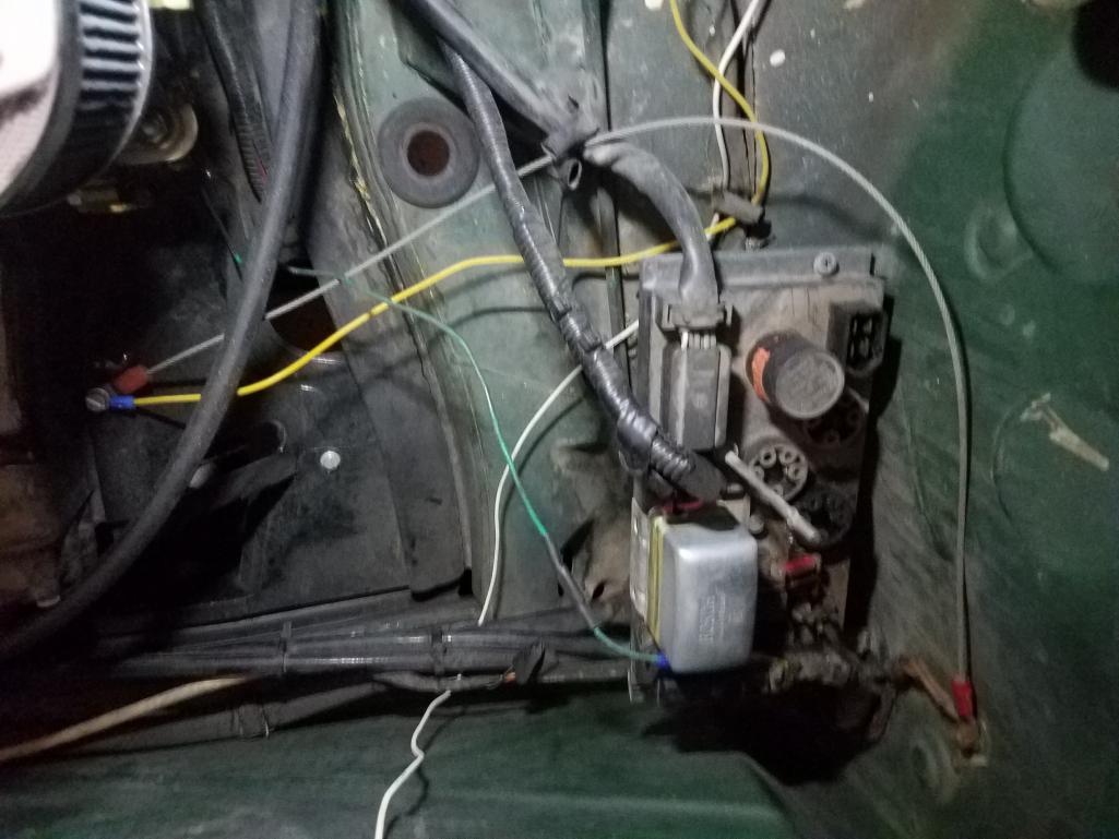
The yellow wire that comes down from the top of the pic and goes over and connects to the screw for the engine tin is the ground wire some PO(S) installed for the license plate lights. The white wire is the other license plate light wire. It goes from where you can see it in this picture, up through a hole that was drilled in the firewall, down behind the back pad, along the drivers side long and then up into the dash by the driver door hinges.
The other/silver "wire" connected to the same engine tin screw is a stainless steel cable that I think was installed as some kind of ground strap.(The other option is that it is there to keep the engine in place while accelerating so the massive torque doesn't rip the engine right out of the car... Yeah, I'm going with dumb @$$ PO ground strap attempt . )
The green wire goes(went) down to the starter solenoid and had four splices in it including the two you can see. Each splice was a different gauge of wire. It is/was the PO(S) attempt at a replacement for the factory yellow wire that goes down to the solenoid. I just couldn't deal with looking at it so I replaced it with a single yellow wire in the correct gauge with much better routing.
The fuel pump comes on when I turn the key to the on position. This is controlled by a switch under the dash which turns the fuel pump on and off when the key is in the on position.
There is some additional non-factory wiring in the tunnel that looks like it is not connected to anything in the engine compartment. I will remove it as I have time to work on the car.
On a semi related note, where is the best place to get the cloth tape the factory used to wrap the wiring harness?
Posted by: Spoke Oct 6 2019, 10:36 PM
I placed a jumper wire between D+ and DF. Started the car and the multimeter showed no voltage change at the battery posts.
Correct me if I am wrong but the light failure should not be an issue when I jumper D+ and DF. Jumpering D+ and DF effectively bypass the light.
Check the bulb resistance with your multimeter. If it is open, it needs to be replaced. Not sure what wattage it is. Someone else should chime in on that.
Jumping D+ to DF will not get the alternator started if the bulb is not in the circuit. The bulb provides a bit of armature field current to get the alternator started. Then D+ will pull up DF and the alternator will produce maximum output of about 17V.
Posted by: Gatornapper Oct 7 2019, 02:17 PM
Spoke -
Bulb is fine, lights brightly both with ignition on, engine not running, and when engine is running.
Remember? I checked to make sure it was 2 watt, which it was, and I still put in a new one.
Weird thing is new Bosch VR charges fine - but GEN light stays on most of the time. New SS VR - light is off, but max. voltage to battery is 12.4 to 12.6.
Still have to do the tests you listed....been busy.....
GN
I placed a jumper wire between D+ and DF. Started the car and the multimeter showed no voltage change at the battery posts.
Correct me if I am wrong but the light failure should not be an issue when I jumper D+ and DF. Jumpering D+ and DF effectively bypass the light.
Check the bulb resistance with your multimeter. If it is open, it needs to be replaced. Not sure what wattage it is. Someone else should chime in on that.
Jumping D+ to DF will not get the alternator started if the bulb is not in the circuit. The bulb provides a bit of armature field current to get the alternator started. Then D+ will pull up DF and the alternator will produce maximum output of about 17V.
Posted by: AZBanks Oct 9 2019, 08:53 AM
I think Spoke's response was for me. Sorry to hijack your thread. I'm having the same or at least a similar issue to what you are facing so I jumped in here instead of creating a new thread.
Spoke -
Bulb is fine, lights brightly both with ignition on, engine not running, and when engine is running.
Remember? I checked to make sure it was 2 watt, which it was, and I still put in a new one.
Weird thing is new Bosch VR charges fine - but GEN light stays on most of the time. New SS VR - light is off, but max. voltage to battery is 12.4 to 12.6.
Still have to do the tests you listed....been busy.....
GN
I placed a jumper wire between D+ and DF. Started the car and the multimeter showed no voltage change at the battery posts.
Correct me if I am wrong but the light failure should not be an issue when I jumper D+ and DF. Jumpering D+ and DF effectively bypass the light.
Check the bulb resistance with your multimeter. If it is open, it needs to be replaced. Not sure what wattage it is. Someone else should chime in on that.
Jumping D+ to DF will not get the alternator started if the bulb is not in the circuit. The bulb provides a bit of armature field current to get the alternator started. Then D+ will pull up DF and the alternator will produce maximum output of about 17V.
Posted by: AZBanks Oct 11 2019, 06:42 PM
I picked up a set of dash light bulbs from the bird. I thought I was getting one bulb so I ordered two. Turn out, I got two sets. If anyone needs a dash light bulb, let me know and I'll drop one in the mail, I have PLENTY!
I swapped out the bulb and nothing changed. Still no light when the key is in the on position.
Posted by: Spoke Oct 11 2019, 07:12 PM
I swapped out the bulb and nothing changed. Still no light when the key is in the on position.
Assume you're talking about the GEN light. Please get your voltmeter, start the car, measure:V+, VD, V-, and Battery to chassis. So much information about the state of the charging system is contained in one of these charging voltage sets. Please take all 4 measurements at the same time. Should take about 1 minute. Write them down and let me know what they are.
Powered by Invision Power Board (http://www.invisionboard.com)
© Invision Power Services (http://www.invisionpower.com)