Printable Version of Topic
Click here to view this topic in its original format
914World.com _ 914World Garage _ Build Thread: Restoration and New School V8
Posted by: Joemo5 Apr 5 2018, 12:07 AM
I probably should have joined 914world and started posting earlier but I have been reading and learning ALOT about these cars already from whats posted in other threads. For that, I thank you guys. I have some catching up to do. Heres my story.
I picked up my first 914 a few months ago as a project car that could eventually serve as a track car or weekend toy. Out of the many different types of cars that would make cool projects, I ended up with the 914 in my crosshairs after I discovered that not only they were mid engine but v8 swaps where not uncommon. Other factors include I had never came across one in the wild, which makes them rare to me. I also like the idea of following in my fathers footsteps with a mid engine european car. He had a Lotus Europa in is 20's. Jumping back the v8 idea though, the added weight of a more powerful drivetrain is at the center of the car, meaning there is a minimal increase in the rotational moment of inertia: the car should retain it's handling characteristics better than a v8 swap in a comparable sized car with a forward mounted engine.
After investigating several craigslist ads that turned out to have missing titles, a friend pointed me towards a local Porsche shop that was known for 914's. Bingo. More 914's than I expected. A few short conversations led to a cheap car that needed some work and was up for grabs. Heres what the '75 2.0l car looked like prior to being yanked out of the weeds.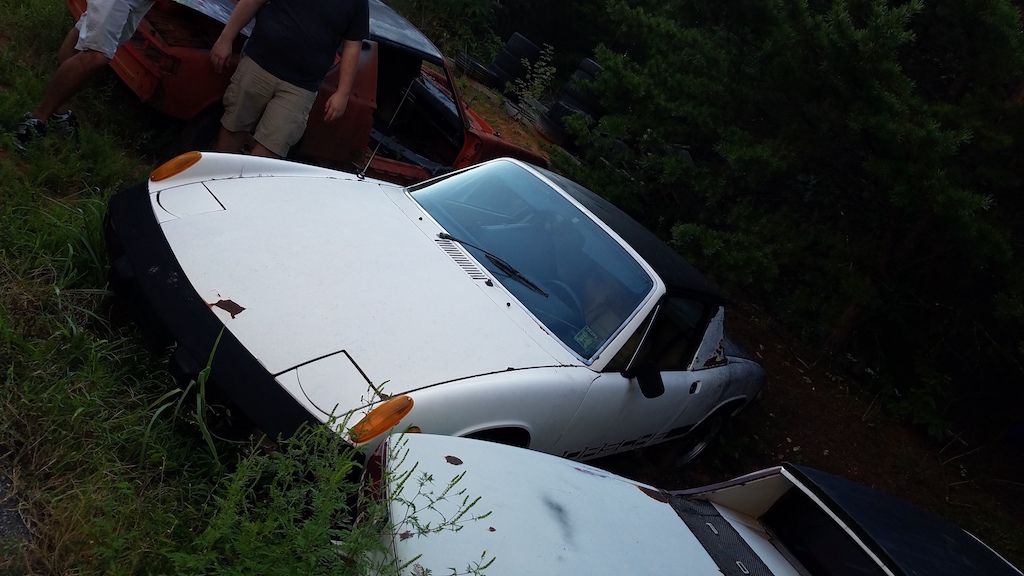
On the trailer headed home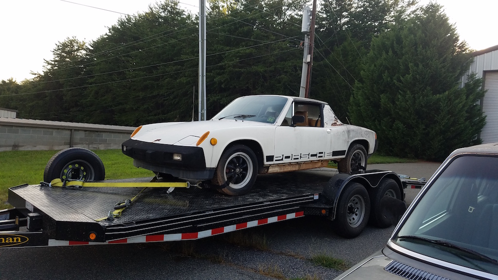
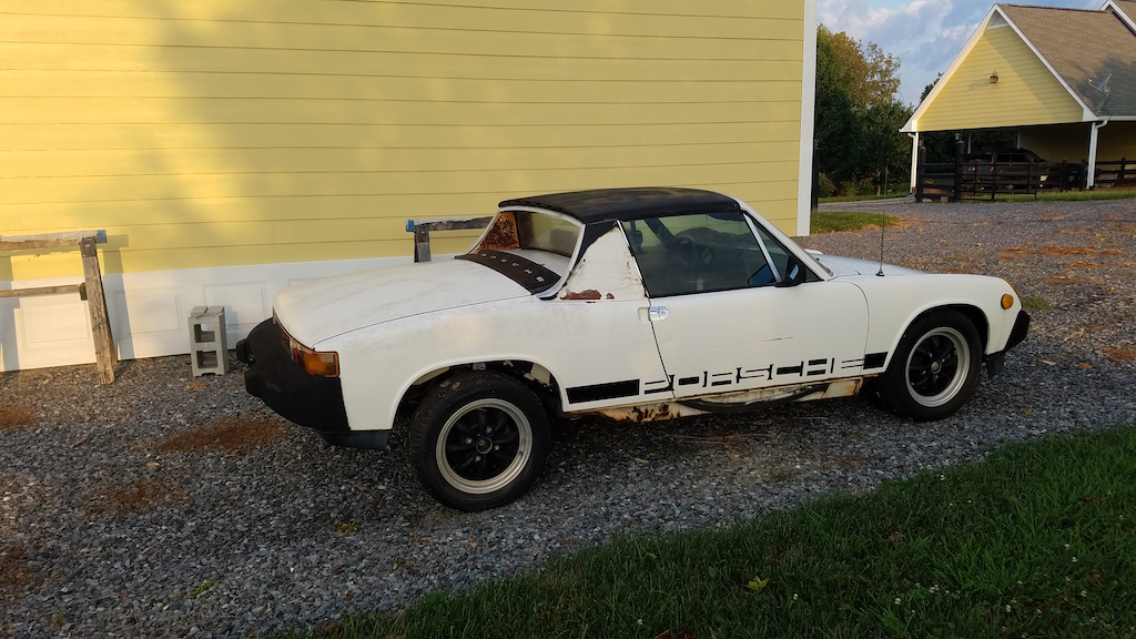
Some of my buddies and I broke out a pressure washer and the car looks good for sitting outside for a year or two.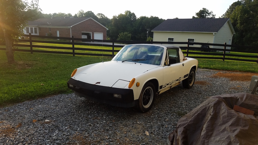
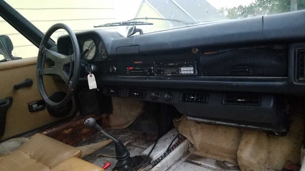
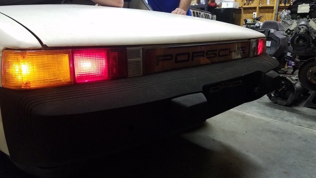
The car did not have the original engine or trans installed when purchased. Although, they were included in the sale. Some tinkering around got some of the electronics working off a jump start box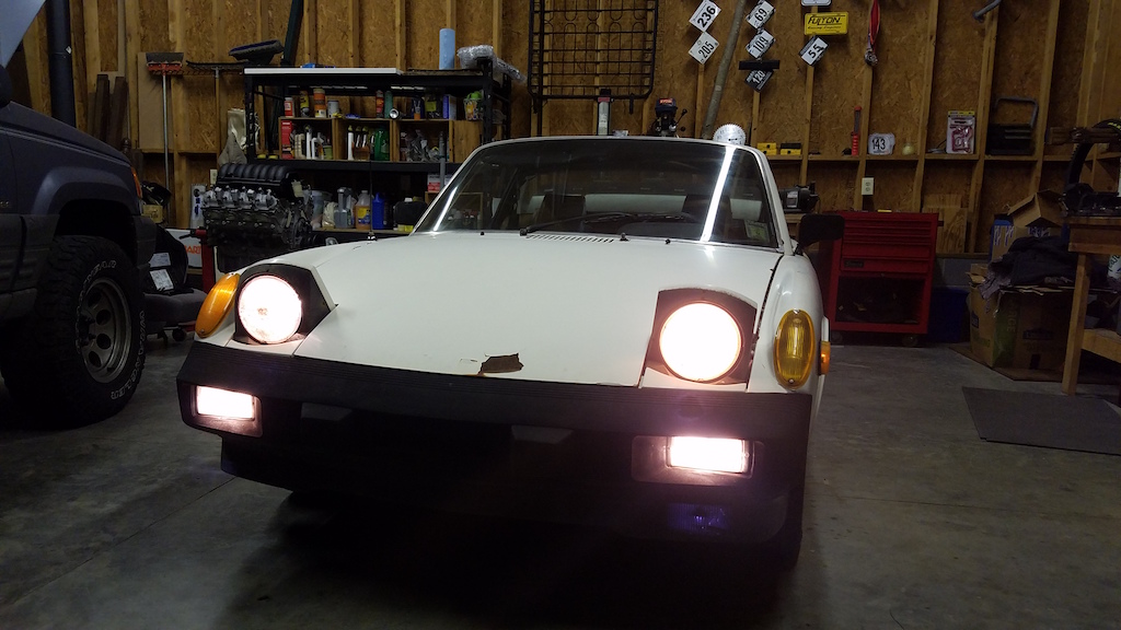
Now heres the fun part. A month or two later, I came across a craigslist deal that would add some originality to the project. An 5.3l L83 out of a 2015 silverado with only "15,000" miles for $1200. 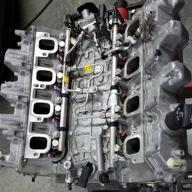
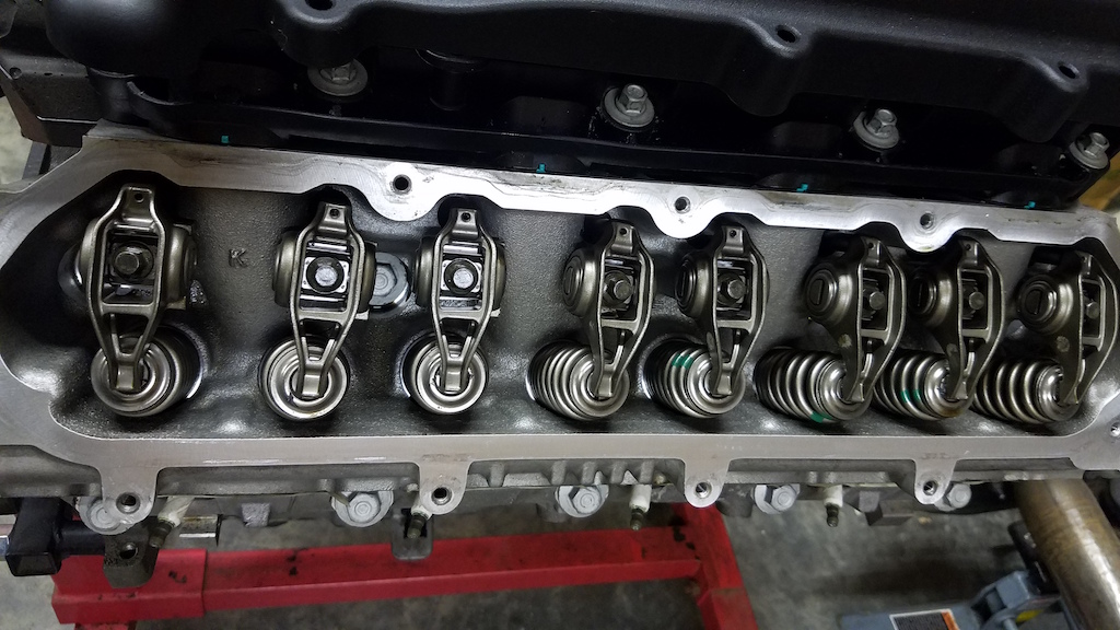
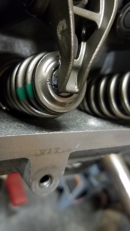
Would an engine with 15,000 miles still have the assembly grease in between the rocker and top of the valve? 
For those of you unfamiliar with this engine: It's NOT an LS, its part of the EcoTec Gen V family. The next generation of Chevy v8 that shares some of the architecture with the LS but with direct injection and variable valve timing. Also its an aluminum block which is different from the Gen IV 5.3 truck blocks which were cast iron. Rumor has it that GM is offering a stand alone kit for the gen V engines which, while costly, would simplify the install a lot.
Quick specs:
Stock 380hp and 416 ft-lbs on e85 fuel.
11.0:1 compression ratio
~400lb dressed. Anyone know how much the original 2.0l engine weighs?
At this point I'm sure most of you have thought: "What does the hell hole look like?" The rot is the worst of all the ones I have viewed online. The only saving grace is that after selling the original motor, trans and wheels, I have made back the purchase price of the car and have a few bucks in my pocket. I have some experience in fabrication and plan on being a sheet metal pro by the end of all this.
Heres a shot of the floor pans and fire wall area. 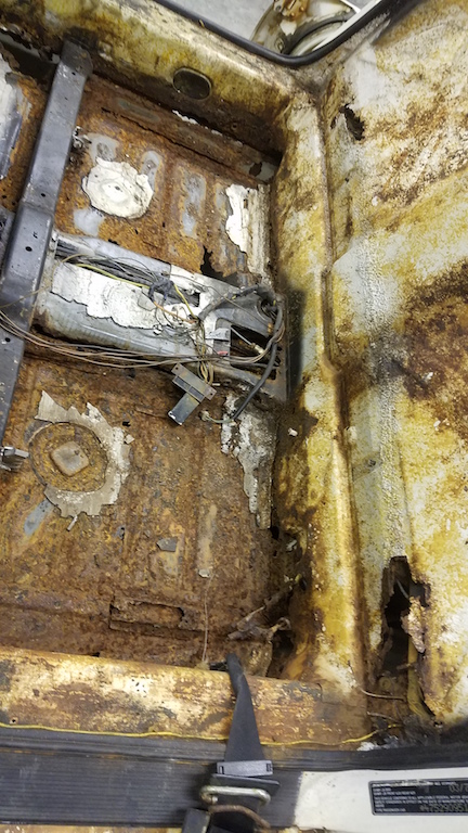
At this point the car is stripped and ready to be mounted on a rotisserie. Lots of bracing prior to mounting on the rotisserie of course. 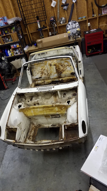
I have more pics and more details but that should do for now.
Attached image(s)
Posted by: Porschef Apr 5 2018, 03:59 AM
Well, that should be fun. Actually looks like a decent starting point, they all need some welding. With that engine, you're probably gonna need some upgrades...

Enjoy
Posted by: mepstein Apr 5 2018, 04:11 AM

Posted by: Cairo94507 Apr 5 2018, 06:17 AM
Nice find and bought the right way for the project you have in mind. I like the aluminum V-8 too. There are plenty of nice V-8 conversions on the World for you to look at and form your own plan as to how you want your car to come together. Keep the pictures coming and have fun with the build. 
Posted by: mepstein Apr 5 2018, 06:34 AM
A stock 914 engine weighs 250-260 with intake and exhaust. 325 with trans.
Posted by: BIGKAT_83 Apr 5 2018, 06:43 AM
Wondered how long it would be before someone used a GenV engine. I suspect most of the early LS clutch and flywheel things will work. I know the engine mounts are in a different location.
The high pressure fuel pump is located under the intake on the engine. What kind of pressure to you need to feed this pump?
Posted by: ValcoOscar Apr 5 2018, 06:58 AM
Great Intro....
This one I'll be following.
Posted by: Andyrew Apr 5 2018, 08:18 AM
That engine looks like fun! Which trans are you going with? Boxster/Cayman S seems like what you need with that kind of torque number.
LOTS of rust repair on the chassis though. Floor pans, and longs at the very least. Probably a suspension console and depending on how you want to do the firewall, some repair on that. Plan at least a year on the rust repair if you work on it every other weekend.
Posted by: Joemo5 Apr 5 2018, 09:56 AM

Wondered how long it would be before someone used a GenV engine. I suspect most of the early LS clutch and flywheel things will work. I know the engine mounts are in a different location.
The high pressure fuel pump is located under the intake on the engine. What kind of pressure to you need to feed this pump?
From what I have read, the feed pump should be 50-60 psi which is common of cars these days. The tricky part is the engine ecu controls a PWM pump in a returnless system.
Posted by: 914forme Apr 5 2018, 10:32 AM
From what I have read, the feed pump should be 50-60 psi which is common of cars these days. The tricky part is the engine ecu controls a PWM pump in a returnless system.
Then lets get into this a bit deeper. What makes that a complicated system? Take what we like to call in the diesel world the feed pump, and mount it as close to the tank as you can get. Run one feed line back to the engine, and to the real EFI high pressure pump. All my diesel are ran this way. Even the tractors are ran like this. These are need because they are all direct injection. Takes a huge amount of PSI to over come the compression on the engine. Diesels normally see, 1500 psi or more on the injector side of the pump.
BTW the feed / boaster/ first pump have a return, it is that most are now mounted in the tank, so the return is just dumped into the tank, no extra lines etc... seen.
Posted by: Joemo5 Apr 5 2018, 11:39 AM
From what I have read, the feed pump should be 50-60 psi which is common of cars these days. The tricky part is the engine ecu controls a PWM pump in a returnless system.
Then lets get into this a bit deeper. What makes that a complicated system? Take what we like to call in the diesel world the feed pump, and mount it as close to the tank as you can get. Run one feed line back to the engine, and to the real EFI high pressure pump. All my diesel are ran this way. Even the tractors are ran like this. These are need because they are all direct injection. Takes a huge amount of PSI to over come the compression on the engine. Diesels normally see, 1500 psi or more on the injector side of the pump.
BTW the feed / boaster/ first pump have a return, it is that most are now mounted in the tank, so the return is just dumped into the tank, no extra lines etc... seen.
Your correct about the direct injection high pressure pump system that's at the engine but the feed/supply pump is Pulse Width Modulated to control the pressure in the line. A pressure switch monitors the fuel line pressure and an electronic control module adjusts the supply voltage frequency to the pump accordingly so that the pump only runs if and as fast as needed. No in tank return system and no excess heat created which may be beneficial considering the front mounted radiator associated with most v8 swaps. I was wrong about the pressure required out of the supply pump. A little more research suggests that too keep the high pressure pump supplied correctly, 72 psi and 45gph is needed from the supply/feed pump. Finding a pump that fits those specs and fits in the 914 tank is the tricky part I was referring to.
Posted by: 914forme Apr 5 2018, 12:00 PM
Okay,
Lots of the Subaru swaps put the stock in tank fuel pump into the the 914 tank. Lots of interesting ways of getting this done. As for the Pulse Width Modulation system of the fuel pump.
http://www.speartech.com/product_p/gen5truckrework.htm
Hope that starts to send you towards your goal. Best of luck.
Posted by: JRust Apr 5 2018, 12:03 PM
Good looking project there. Love the v8 setup & hope you do the Boxtser S transmission. Awesome LS setup. Looking forward to that coming together. Lot's of metal work needed. That is a little easier when you aren't as concerned about it being stock. Give's you more options on how to do things. There are quite a few great build here that really go extreme on metal fab work. You are in the right place
Posted by: Andyrew Apr 5 2018, 12:35 PM
From what I have read, the feed pump should be 50-60 psi which is common of cars these days. The tricky part is the engine ecu controls a PWM pump in a returnless system.
Then lets get into this a bit deeper. What makes that a complicated system? Take what we like to call in the diesel world the feed pump, and mount it as close to the tank as you can get. Run one feed line back to the engine, and to the real EFI high pressure pump. All my diesel are ran this way. Even the tractors are ran like this. These are need because they are all direct injection. Takes a huge amount of PSI to over come the compression on the engine. Diesels normally see, 1500 psi or more on the injector side of the pump.
BTW the feed / boaster/ first pump have a return, it is that most are now mounted in the tank, so the return is just dumped into the tank, no extra lines etc... seen.
Your correct about the direct injection high pressure pump system that's at the engine but the feed/supply pump is Pulse Width Modulated to control the pressure in the line. A pressure switch monitors the fuel line pressure and an electronic control module adjusts the supply voltage frequency to the pump accordingly so that the pump only runs if and as fast as needed. No in tank return system and no excess heat created which may be beneficial considering the front mounted radiator associated with most v8 swaps. I was wrong about the pressure required out of the supply pump. A little more research suggests that too keep the high pressure pump supplied correctly, 72 psi and 45gph is needed from the supply/feed pump. Finding a pump that fits those specs and fits in the 914 tank is the tricky part I was referring to.
You can always just run a surge tank and then go with a high end pump like a Bosch 044. This is what I have, I put the tank in the engine bay and have a carb pump feeding into the surge tank. My setup shouldnt run out of fuel till ~600hp on E85, and Im not likely to turn it up that much...
Posted by: tazz9924 Apr 5 2018, 12:35 PM
Okay,
Lots of the Subaru swaps put the stock in tank fuel pump into the the 914 tank. Lots of interesting ways of getting this done. As for the Pulse Width Modulation system of the fuel pump.
http://www.speartech.com/product_p/gen5truckrework.htm
Hope that starts to send you towards your goal. Best of luck.
When i did my Subaru swap i got a walbro 255 that i mounted in the engine bay right off my stainless steel fuel lines
Posted by: burton73 Apr 5 2018, 02:46 PM
Bob B
Posted by: 914forme Apr 6 2018, 12:54 PM

I was suggesting he modify the 914 gas tank to accept the PWM in tank fuel pump used from his donor. In this case a Chevy / GMC pickup truck.
This would allow him to keep the same factory setup and fuel pump used in the original vehicle. The difference with the PWM is that it modulates the pressure to feed the fuel to the high pressure pump. On the Gen V that high pressure pump can reach pressures as high as 2500 PSI at the injector. To achieve this high pressure unfortunately it does not have a lot of ability to draw fuel into the pump. That is why it has the booster fuel pump. It is used to push the fuel into the high pressure pump.
The Gen V is a neat little engine, nothing revolutionary in it's design, just well put together. As the aftermarket support increases for this engine it will help keep hot rodding alive and well for years to come.
Watching this one come together, and making me think about the conversion myself.
Posted by: Joemo5 Apr 7 2018, 11:20 AM
I was suggesting he modify the 914 gas tank to accept the PWM in tank fuel pump used from his donor. In this case a Chevy / GMC pickup truck.
This would allow him to keep the same factory setup and fuel pump used in the original vehicle. The difference with the PWM is that it modulates the pressure to feed the fuel to the high pressure pump. On the Gen V that high pressure pump can reach pressures as high as 2500 PSI at the injector. To achieve this high pressure unfortunately it does not have a lot of ability to draw fuel into the pump. That is why it has the booster fuel pump. It is used to push the fuel into the high pressure pump.
The Gen V is a neat little engine, nothing revolutionary in it's design, just well put together. As the aftermarket support increases for this engine it will help keep hot rodding alive and well for years to come.
Watching this one come together, and making me think about the conversion myself.
I agree that the best option would be to use the pump from the doner and associated control system which is what I will try to do. However, that Speartech link you posted has info about using a normal high flow pump and vacuum referenced pressure regulator. So apparently someone out there has done it without the fancy PMW system. Honestly though, I'm a long way off from having to make fuel system decisions.
Posted by: Maltese Falcon Apr 7 2018, 11:50 AM
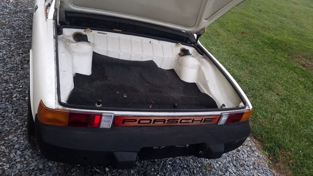
looks like the PO had an aftermarket a/c going on in the front trunk  If you plan to exit your spent radiator air out the bottom, you have a head start ...just close up what you don't need !
Posted by: Andyrew Apr 7 2018, 12:51 PM
looks like the PO had an aftermarket a/c going on in the front trunk If you plan to exit your spent radiator air out the bottom, you have a head start ...just close up what you don't need !Generates to much lift under the car at speed. Wheel well or hood exhaust would be my only choices
Posted by: Maltese Falcon Apr 7 2018, 03:30 PM
looks like the PO had an aftermarket a/c going on in the front trunk If you plan to exit your spent radiator air out the bottom, you have a head start ...just close up what you don't need !Generates to much lift under the car at speed. Wheel well or hood exhaust would be my only choices
Absolutely what Andyrew is saying...however I've used small portions of the trunk floor (The 2 knockout circles ) for my oil cooler spent- air exits... NO high speed lift whatsoever ; but on my current v8/ radiator build I'm going out the top^^^ Ford gt40 style all the way

Posted by: Joemo5 Apr 8 2018, 11:07 AM
Good looking project there. Love the v8 setup & hope you do the Boxtser S transmission. Awesome LS setup. Looking forward to that coming together. Lot's of metal work needed. That is a little easier when you aren't as concerned about it being stock. Give's you more options on how to do things. There are quite a few great build here that really go extreme on metal fab work. You are in the right placeThanks! That transmission is definitely what I'm leaning towards at the moment. Specifically the G86.20 out of 2000-2004 Boxster S. Mostly because there seems to be the most support for that model and it has acceptable gearing for a V8. Thats also the go to trans for Renegade hybrids. I wonder if there is anyone on 914 world with that trans that could share their experience?
Posted by: Joemo5 Apr 8 2018, 11:42 AM
I have been tied up doing transmission repairs on my daily, a 06 Subaru LGT. So in the mean time I've been playing around with an excel sheet left over from a college assignment. The idea being to get an idea of how the Boxster gearing plays out with a 914 and 5.3L EcoTech. Hopefully, the screen shots are legible.
Here are my inputs. Note that the 7000 rev limiter is high. Realistically, 6500 would be a better limit point with valve spring and push rod changes for the 5.3L to live happily. 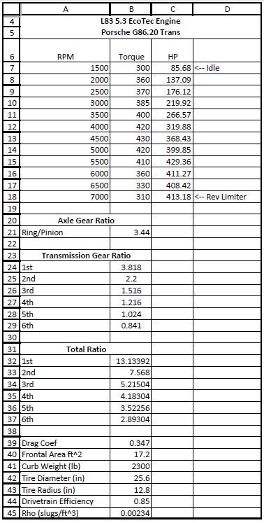
I pulled my torque data from the stock graph shown here
https://5startuning.com/product/2014-2016-chevygmc-silveradosierra-5-3l-1500-texas-speed-performance-l83tr-1-camshaft/
Plotted my points and calculated and equation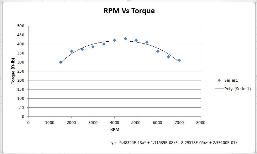
Found gear ratio's for the G86.20 trans from here
https://californiamotorsports.net/pages/porsche-986-boxster-transaxle-specifications
Below shows engine speed in each gear. Note this is for a rear 275/40R17 tire. (flares are definitely in my future) The blacked out area's are above the rev limiter or below idle. 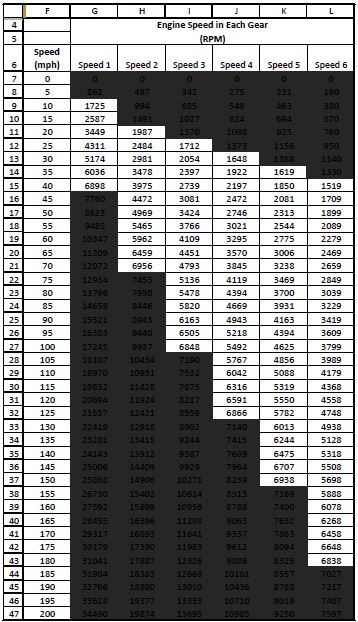
Using the equation calculated above and the gearing for the G86.20 determined the force the tire could potentially exert on the road in each gear "tractive force". I then used the drag coefficient and frontal area found in this link...
http://www.cassidy-online.com/porsche914/aerodynamic_aids/index.html
... to determine aerodynamic drag for the range of speeds shown. Note the drag coefficient and frontal area are for a narrow body car without a spoiler or front splitter. So realistically, I imagine the drag force would be higher. I also calculated a force induced by rolling resistance of the tire for range of speed shown. However, I feel less confident in that calculation but figured it plays a role so I included it. Below is a graph of "resistive force" (areo + rolling resistance) and "tractive force" in each gear shown in the Y axis and speed in the X axis.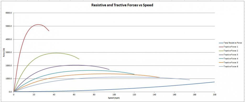
Subtracting the resistive forces from tractive forces gives an overall force applied to the car causing acceleration. Using the weight of the car (~2300lbs) you could come up with an acceleration in G's shown below in each gear, at each speed. Again, blacked out area's are either above 7000 rpm or below idle. 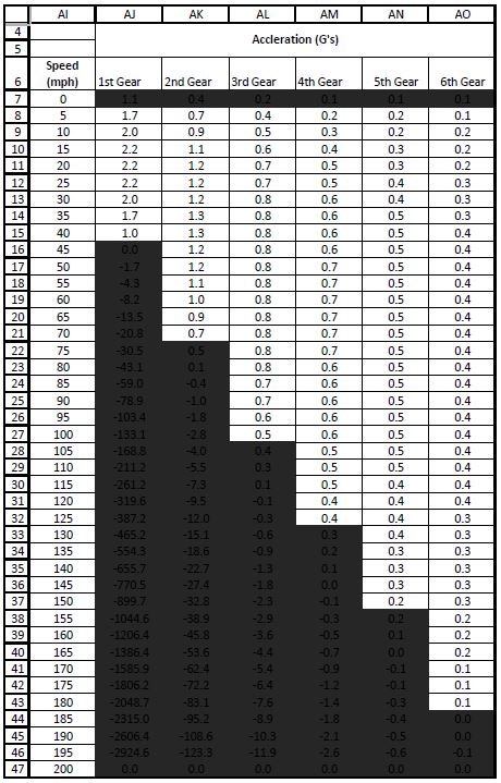
It's probably worth taking all this with a grain of salt.. there are a million and one variables not included that could affect any of the above. The car probably won't accelerate at 2G's either. More likely is a smoke show and a slightly smaller tire diameter. 
Posted by: Joemo5 May 7 2018, 09:57 PM
Well I have been busy and hope to stay busy. With as much metal work as this car needs, a rotisserie is in needed. So I'm going to build one based off the blue sky motorsports plan. In the process of stripping the car I realized there is a lot of rust to the passenger side frame rail along with a nice dent (pics to come later). Thus I need a good way to keep the car straight while repairs are made so I came up with this. 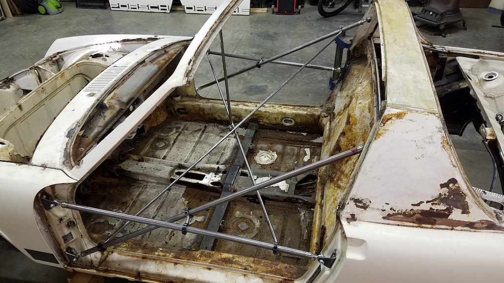
The idea is that triangles are stiff and tying each support to one another should do a good job at preventing any sagging or deformation. This is my first go at a rotisserie restoration so those who are experienced, please feel free to chime in on ways you have prevented the dreaded sagging frame that I've read about. When the doors were removed the gaps looked great. Lets hope they stay that way.
Here's some more detailed pics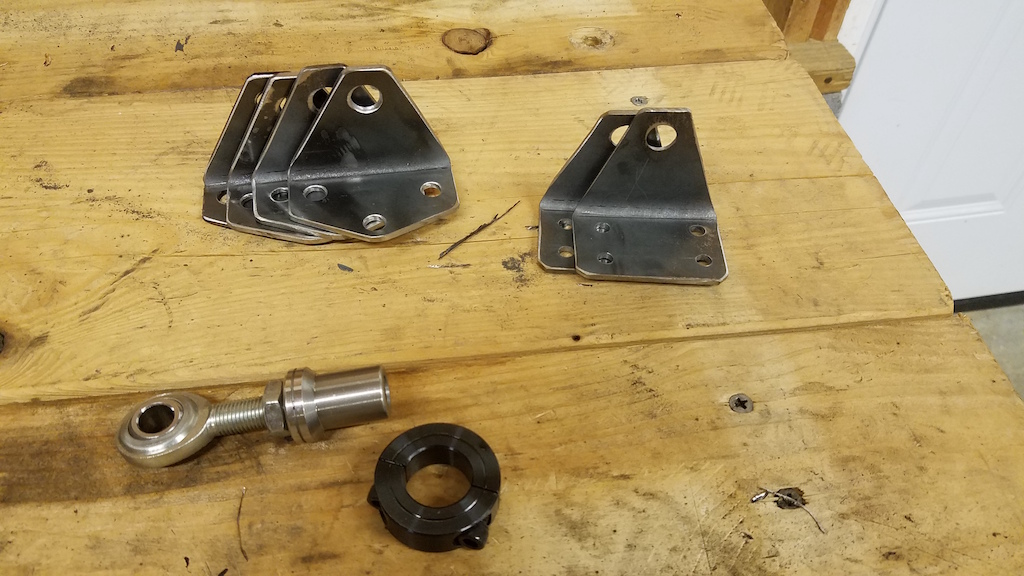
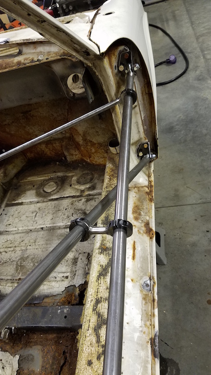
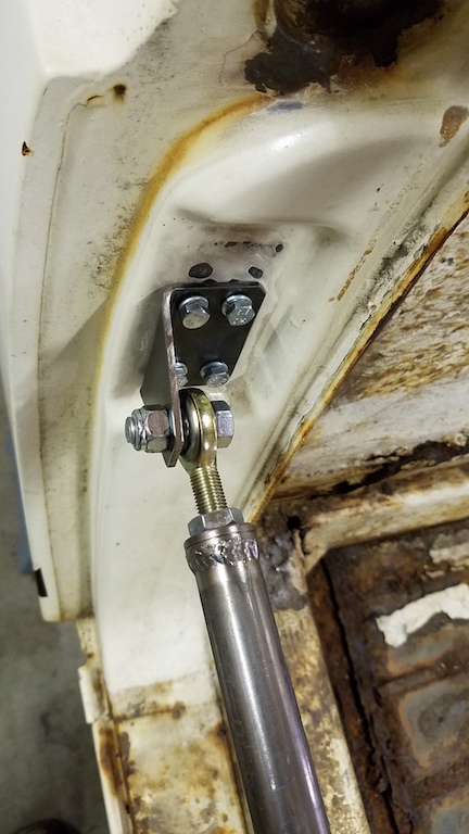
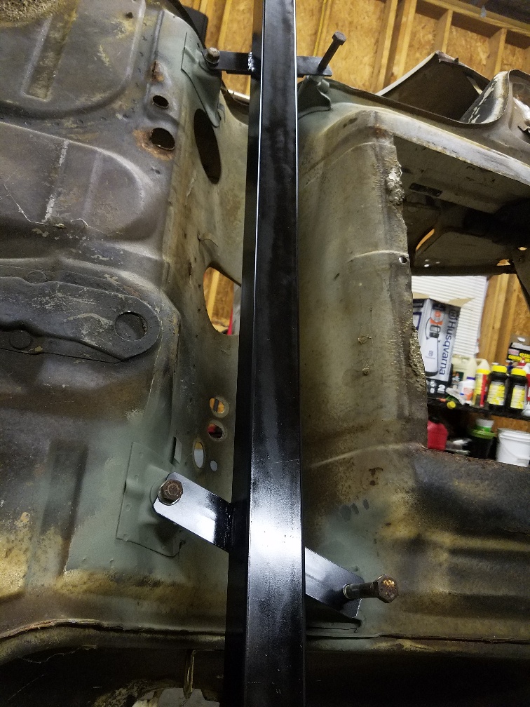
The entire system is modular and bolts in except for the vertical tube in the center that is tack welded to the underside of the windshield frame.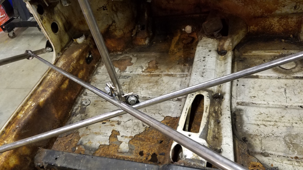
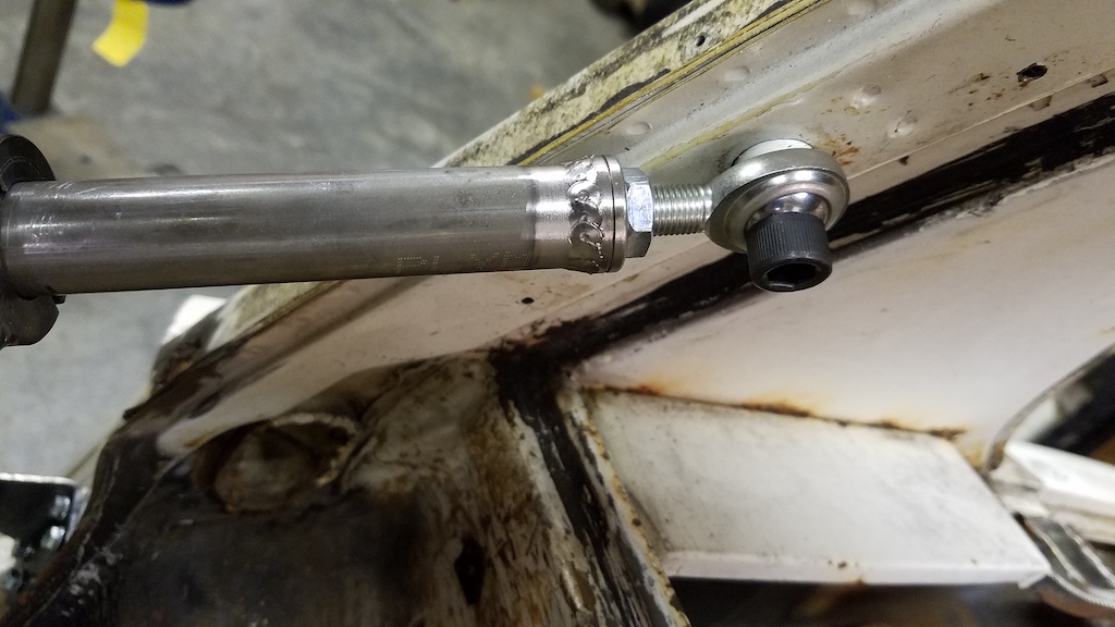
All the small diameter tubing is clamped to the larger tubing via shaft collar. Which should allow adjustments to be made to the length of the larger tubing members if the chassis where to flex. 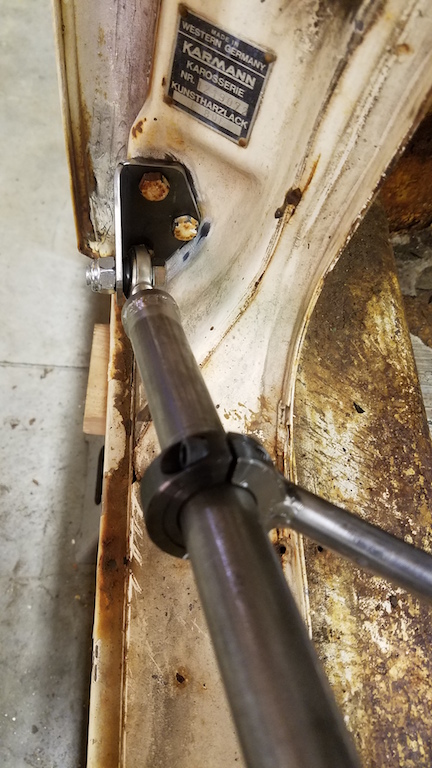
Lastly, heres a start on the rotisserie. 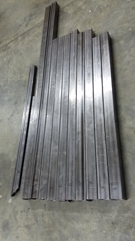
Posted by: mgp4591 May 8 2018, 12:25 AM
Wow, that's an amazing bracing system - great job! Now I'm fearing that mine isn't going to be enough... 
Posted by: mepstein May 8 2018, 05:05 AM
looks like the PO had an aftermarket a/c going on in the front trunk If you plan to exit your spent radiator air out the bottom, you have a head start ...just close up what you don't need !Generates to much lift under the car at speed. Wheel well or hood exhaust would be my only choices
Absolutely what Andyrew is saying...however I've used small portions of the trunk floor (The 2 knockout circles ) for my oil cooler spent- air exits... NO high speed lift whatsoever ; but on my current v8/ radiator build I'm going out the top^^^ Ford gt40 style all the way
I did the same thing. The two knockout circles are easy to remove and easily reversible.
Posted by: Joemo5 May 29 2018, 10:30 PM
looks like the PO had an aftermarket a/c going on in the front trunk If you plan to exit your spent radiator air out the bottom, you have a head start ...just close up what you don't need !Generates to much lift under the car at speed. Wheel well or hood exhaust would be my only choices
I am fond of the hood exit however, with a radiator and the front tower support there isn't much room a smooth transition. With either the hood exit or the fender well exit, I guess getting caught in the rain wouldn't be good? Some deutsch connections would take care of the electronics but it still seams like it would trap water.. assuming the car still had a complete trunk floor unlike mine.
Posted by: Joemo5 May 29 2018, 10:41 PM
Wow, that's an amazing bracing system - great job! Now I'm fearing that mine isn't going to be enough...
Thanks! I'd imagine it depends on how much of the longitudinal your planning on replacing. Since mine are nearly gone, I need all the stiffness I can get.
Posted by: Joemo5 May 29 2018, 10:51 PM
So the rotisserie is starting to take shape. Trying to hold back and go by the KISS method since this is just a means to an end..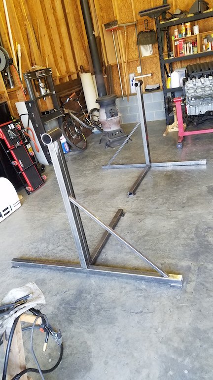
I went decided to veer away from the blue sky motorsports plans slightly with a different locking mechanism. Theres a plate with holes and spring pin that will catch the holes a set locations and a nut/bolt clamp that locks on that plate to really keep things from moving when needed. 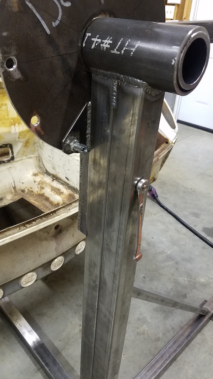
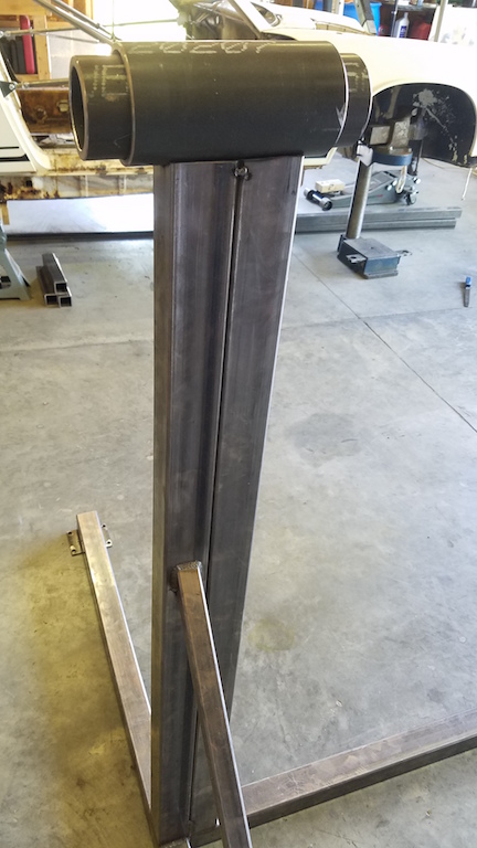
Posted by: Joemo5 Jun 5 2018, 08:35 PM
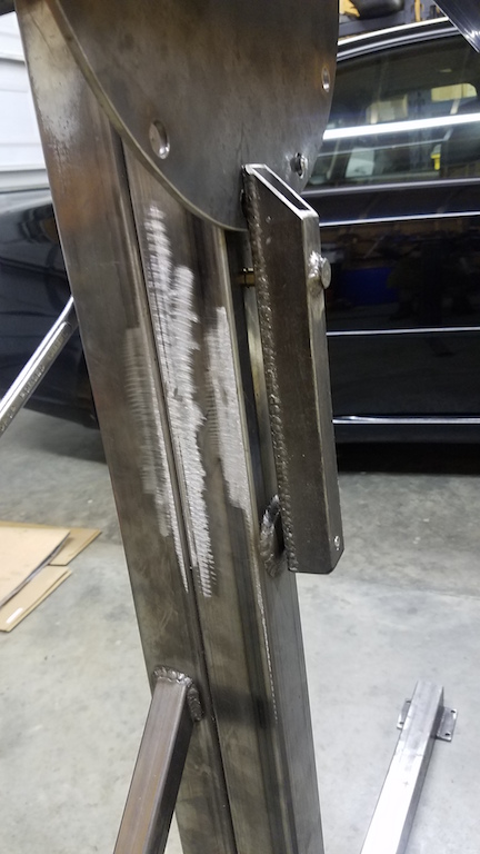
The rotisserie is complete and the car is mounted. Here is the finished rotisserie. I wish I made a beefier tie bar between the front and rear supports. That may be a wise investment. 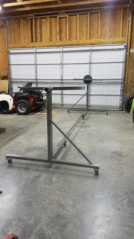
Heres a overview of the locking end. 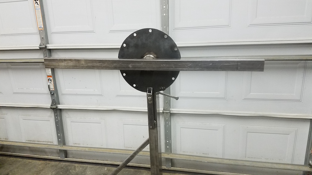
And here she is mounted up. We have had ridiculously humid weather recently, so I painted all the bare steel on the door supports and the rotisserie. 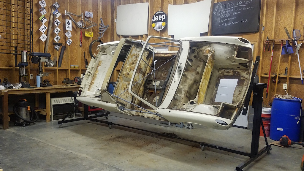
Posted by: Joemo5 Jun 5 2018, 09:37 PM
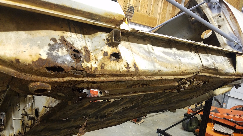
Here's some good pics of the worst section on the car. The passenger long is not only rusted through near the hell hole, it's also crushed from who knows what. 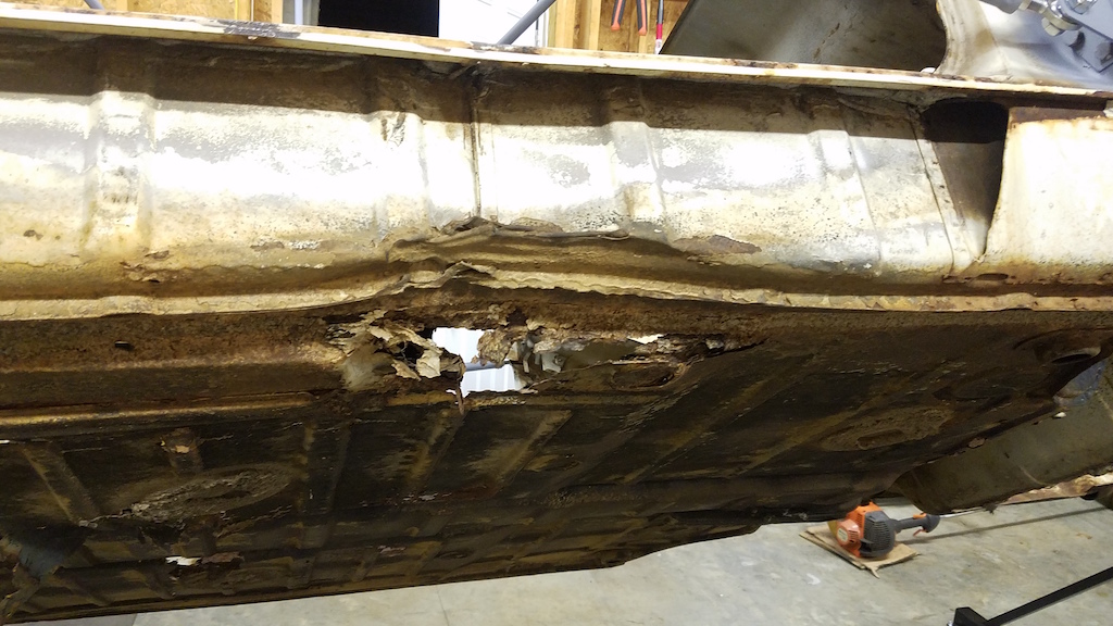
So at this point I'm wondering if it would be easier in the long run to get the entire thing blasted or dive in repairing the major problem areas?
On a less serious note.. 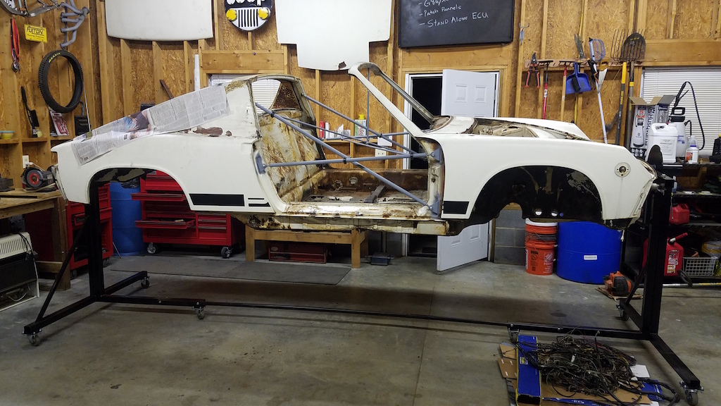
Posted by: mbseto Jun 6 2018, 08:07 AM
This looks like the start of a really cool project.
Posted by: Joemo5 Jan 27 2019, 11:34 PM
With a ton of sheet metal work still to do, it wasn't my intention to move forward with purchasing drivetrain components but I found a deal I couldn't pass up.
I had been looking at wrecked Boxster S's on Copart, a online auction website. The thought was; it might be possible to buy one, keep the transaxle and part out the other stuff too re-coupe most of the initial cost. Ironically, a junkyard a few minutes from my house bought a 2003 Boxster S I had my eye on. After talking to the guy, I got to see it run and drive and point out exactly what pieces and parts I wanted, so I went for it.
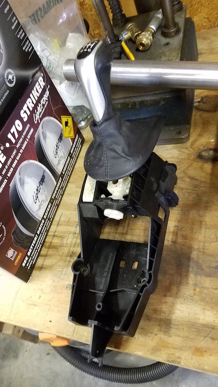
Ended up taking home the G86.20 trans, mounting brackets and rubber isolators, shifter cables, the shifter, the boxster center console and the Brembo brakes. 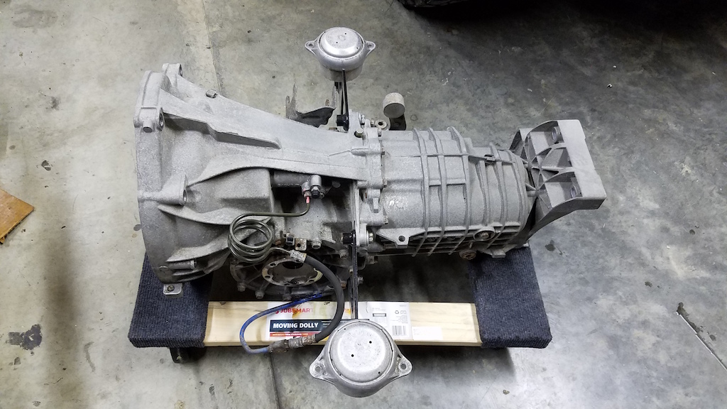
I didn't get the rotors because it looked like most people are using a rotor off a 930 carrera but that's with the non-S caliper's. I can't help but wonder if the Boxster S rotor's could be used with the correct caliper adapter? The bolt pattern for 5 lug conversions is 5x130 and so is the Boxster S. 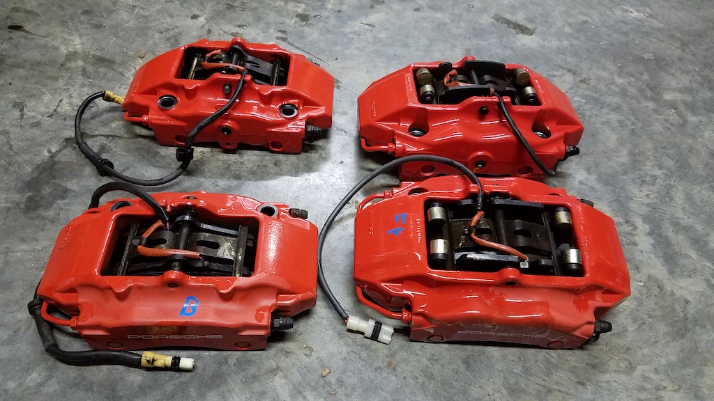
Posted by: Mueller Jan 27 2019, 11:49 PM
That is going to be a really nice build.
Many of us use the standard Boxster calipers since they will fit under 15" rims.
Posted by: 76-914 Jan 28 2019, 10:49 AM
What is the going rate on the G86 trans?
Posted by: Joemo5 Jan 28 2019, 05:17 PM
What is the going rate on the G86 trans?
$1700 for trans, shifter, and cables. It's got 98,000 miles on it which is high in comparison to other ones on the market but I got to see it run and drive which counts for something.
That is going to be a really nice build.
Many of us use the standard Boxster calipers since they will fit under 15" rims.
Thanks! I figured there was a reason there's less info out there on the "S" calipers.
Posted by: jimkelly Jan 28 2019, 05:39 PM
good amount of rust but clearly you are up for the challenge.
might want to consider a long reinforcement kit on top of all the repair you are gonna do?
https://www.pelicanparts.com/More_Info/INLONG002.htm?pn=IN-LONG-002& amp;gclid=Cj0KCQiA7briBRD7ARIsABhX8aAYo0DI67ONFOdD99w4F4Jgyqs8GoegUD6JSfjqZz_d6u
UiveyjMz0aAmwgEALw_wcB
Attached image(s)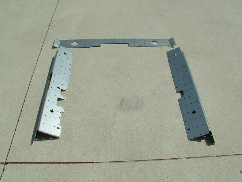
Posted by: Joemo5 Jan 28 2019, 06:36 PM
good amount of rust but clearly you are up for the challenge.
might want to consider a long reinforcement kit on top of all the repair you are gonna do?
https://www.pelicanparts.com/More_Info/INLONG002.htm?pn=IN-LONG-002& amp;gclid=Cj0KCQiA7briBRD7ARIsABhX8aAYo0DI67ONFOdD99w4F4Jgyqs8GoegUD6JSfjqZz_d6u
UiveyjMz0aAmwgEALw_wcB
I'm definitely going to add reinforcements. A roll cage is a no brainer but tying in to the suspension points, rear roll hoop and A pillars should help add in torsional rigidity. While I haven't done enough research into this yet, it seams like a lot of these V8 swaps end up turning a 2100 lbs car into a 2600+ lbs sled. Since my engine and drivetrain choices have added ~250lbs without including the cooling system and supporting equipment, I will try to add reinforcements (weight) very wisely.
Posted by: 914forme Jan 28 2019, 09:45 PM
If your not into originality this is the best system I have found to fix bad rockers, they really stiffen up the car. Still need o fix the rust but these and the Maddog kit, makes a very stiff chassis.
"Excellent for repairing longitudinal and jack receiver rust. Also extensively used for competition chassis stiffening and large engine installations. The panels are .100 thick (very strong) and extend from front wheel house to the outer rear suspension console. Welding is required. The rear section of the panel sandwiches between the outer suspension console and the trailing arm. Permanently restores door gap and eliminates flexing problems. Provides a base to weld to if additional repair is needed in floors, inner longitudinal, or firewall area. Excellent installation instructions included plus my personal assistance if you have questions. I have been selling and installing these for 28 years. There is nothing on the market for 914 chassis repair that is this strong, proven or easy to install. Porsche repair and restoration expert for 38 years.
Free Shipping.
"
Lifted from 914LTD http://914ltd.com/store.php?c=1384303079 is where you can order, Brad is a very nice guy and supporter of our hobby.
Posted by: 914forme Jan 28 2019, 09:59 PM
BTW, Brad's front and rear sway bar mounts are very nice. The front design is great and does not require cutting the car inner box section under the fuel tank.
Posted by: TravisNeff Jan 29 2019, 08:32 AM
How did you get the car up onto the rotisserie? I always wonder how this is done without a lift.
Posted by: Joemo5 Jan 29 2019, 07:13 PM
@http://www.914world.com/bbs2/index.php?showuser=2388 @http://www.914world.com/bbs2/index.php?showuser=2460 Thanks for the links to stiffener kits. The outside kit looks interesting in the fact that it runs all the way back to the suspension console.
I was lucky enough to have sway bars from the factory but that's not to say it couldn't be improved on.
Posted by: Joemo5 Jan 29 2019, 07:36 PM
How did you get the car up onto the rotisserie? I always wonder how this is done without a lift.
A few buddies lifted and another pushed the stand onto the pivot. Once stripped, these cars don't weigh much at all.
Posted by: ConeDodger Jan 30 2019, 10:59 AM
@http://www.914world.com/bbs2/index.php?showuser=12094 needs to get involved here I think...
Posted by: Joemo5 Mar 3 2019, 11:37 PM
I've spent a day drilling out spot welds and got part of the floor pan removed. I didn't want to remove all of the front portion until I knew how far up the replacement went. A rather large order to Restoration Design is in my future.
Here's the removed section. "Rust bucket" is an appropriate description.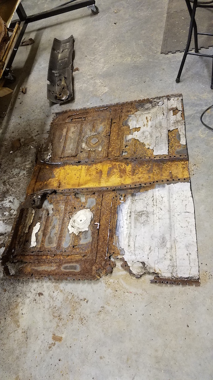
Here's the car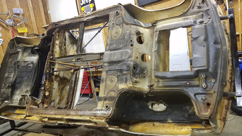
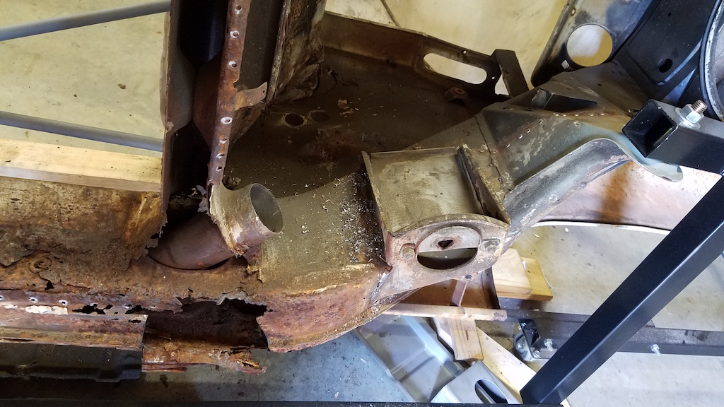
As I mentioned before, the most concerning portion of the car is the passenger longitudinal. Looking at this, I'm not sure how the car didn't sag or have misaligned door gaps. 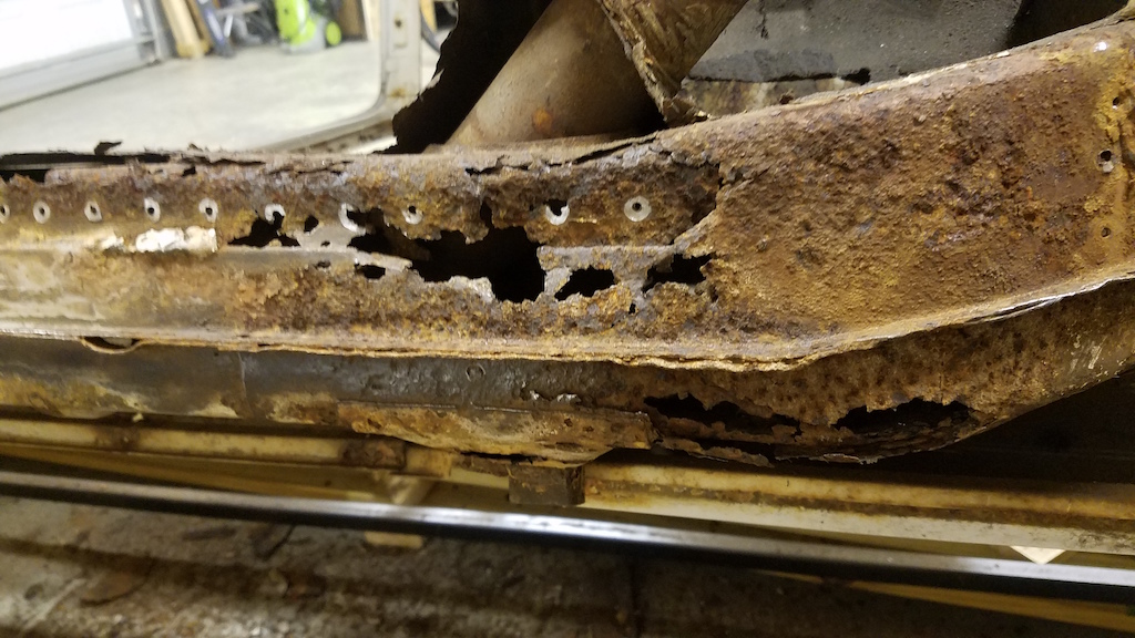
The rotisserie has been extremely convienent but I still worry about the two halves moving or becoming misaligned since both the inner and outer portion of the longitudinal have to be replaced. I'm thinking about tying the front suspension points to the rear suspension console via a brace of some sort. "Temporary frame rails" if you will. Of course, if either suspension console needs to be replaced this idea is useless.
Here's a look into that hole in the passenger longitudinal, looking back at the suspension console. The rust doesn't look nearly as bad as I had imagined near the suspension console. 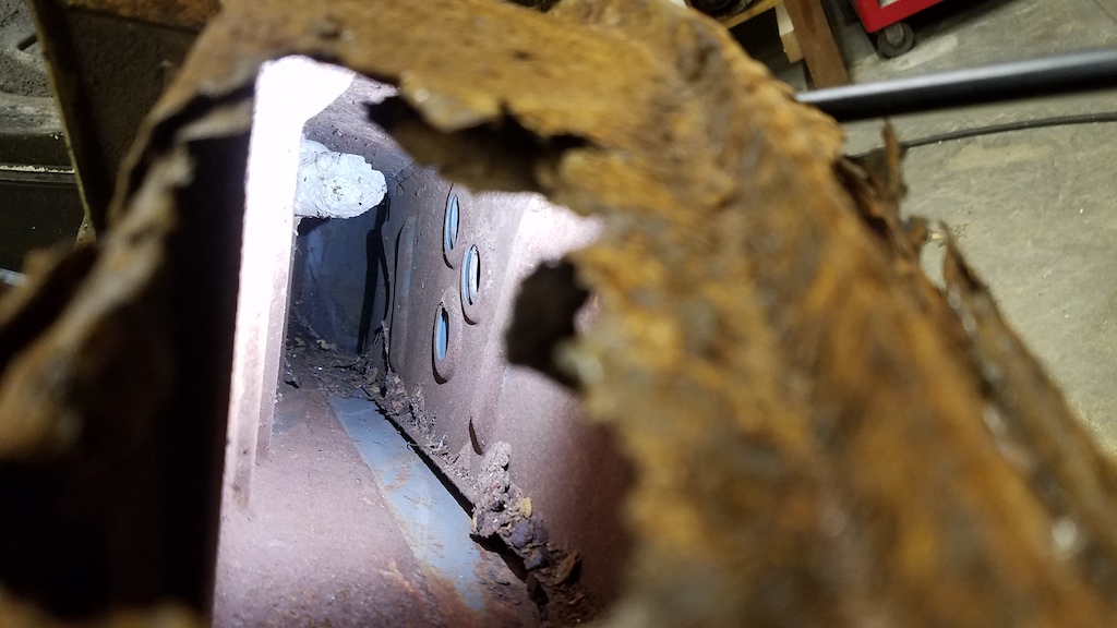
Posted by: Joemo5 May 20 2019, 06:35 PM
Several updates: Bought the major frame rail components from Restoration Design. 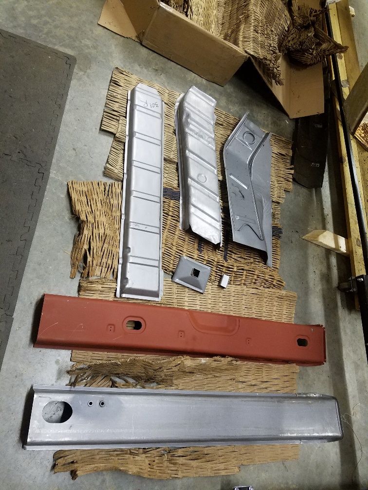
Built a lower support structure that ties the front and rear suspension points together. 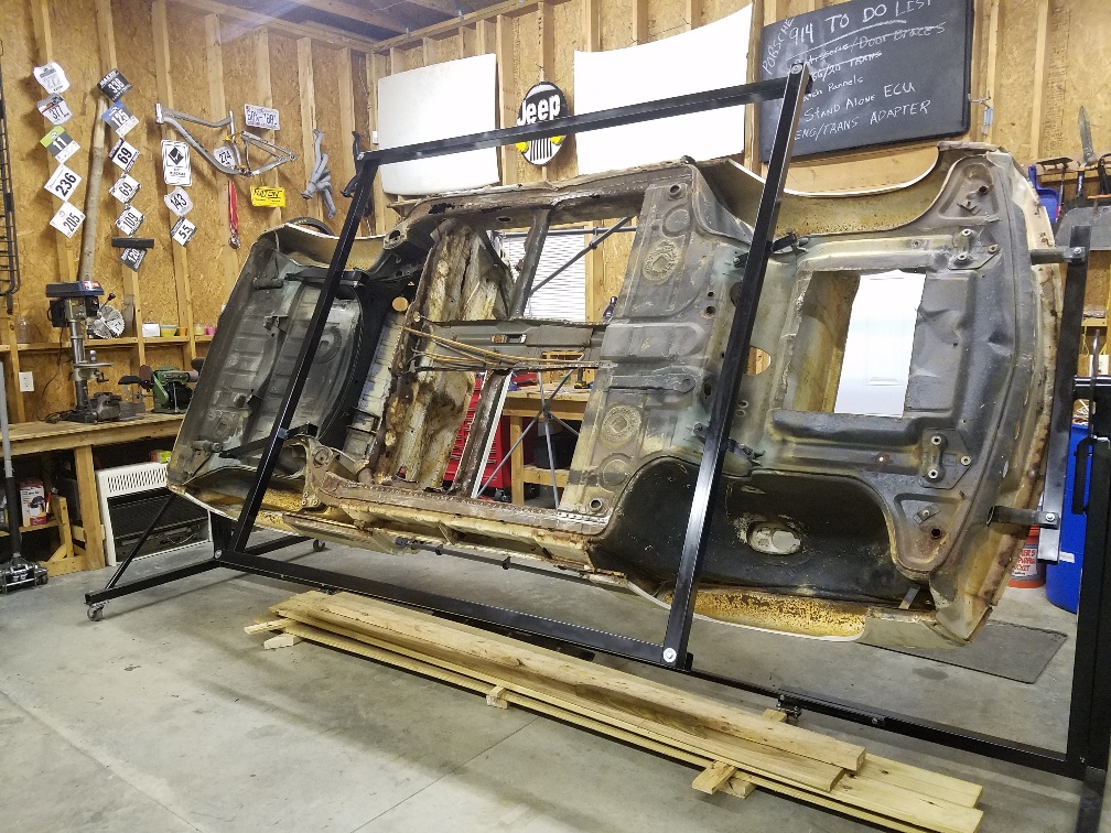
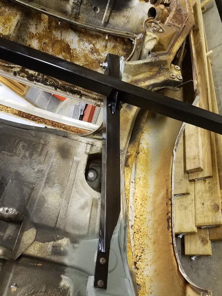
The idea here is to add additional support when the frame rails are cut out, and be able to test the torsional rigidity of the chassis as modifications are made. The rails that are parallel to the longs can be removed. Using the remaining rails should allow me to twist the car and measure the deflection. I really want to know what I'm getting when I make mods. Of course I wont do any of this testing until the rotten longs are repaired so that the chassis isnt permanently twisted out of wack.
Stiffening mods planned: Seam welding, roll cage, structural foam? and longitudinal stiffening.
Here's where I want input: Has anyone done any sort of internal stiffening for the longs on the 914? My primary goal is safety. Think side impact with a SUV. Second goal is minimal weight added and third is improved handling from a stiffer chassis.
I want to thank those who have shared the kits that weld on the outside or inner of longs. Those are still on the table. I found some really interesting stuff about structural foams used on Infinity brand cars but I'm not at that point yet. I'm planning on running the water lines down the inside of the frame rails and wondered if a metal tube liner that was welded at each end along with cross sections could add some stiffness.
Posted by: Joemo5 Aug 24 2019, 06:55 PM
I really need to update more frequently..
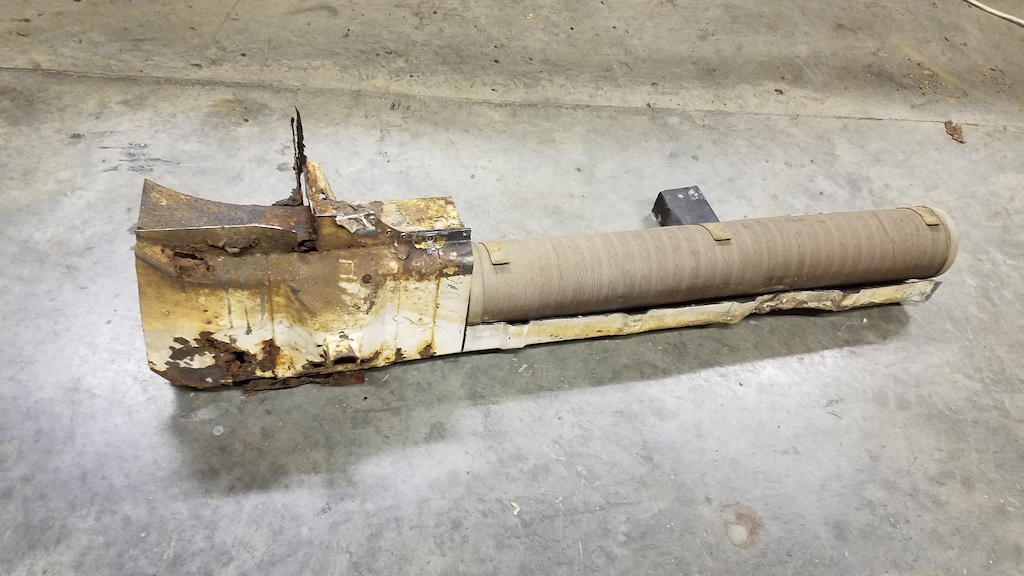
So I took the plunge and just cut out a large section of the rotten frame rail. The idea here is that I can look back at it in one piece to see how the replacements should fit. Here's some pics that show the process with before and after.
Looking at the outside: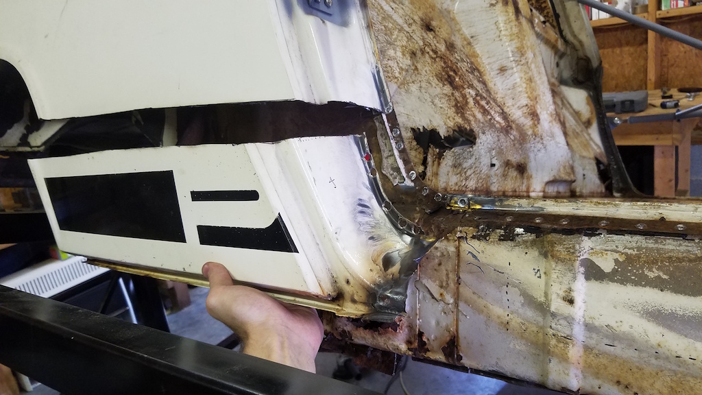
I didn't cut the entire long off so that I had a reference point for the new panels. It's going to mean lots of welding. Warpage is something I'm concerned about. 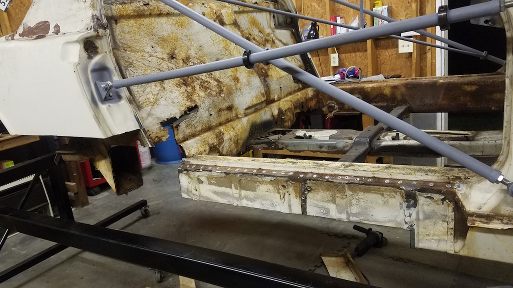
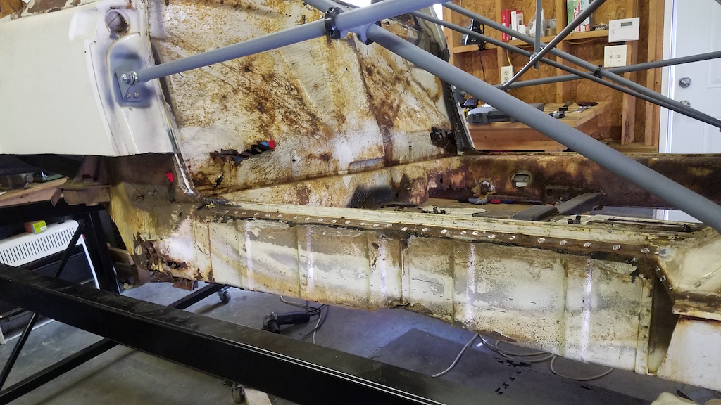
Looking from the inside: 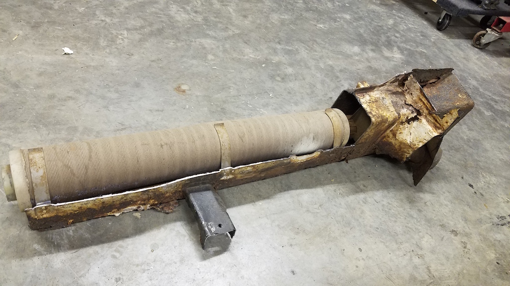
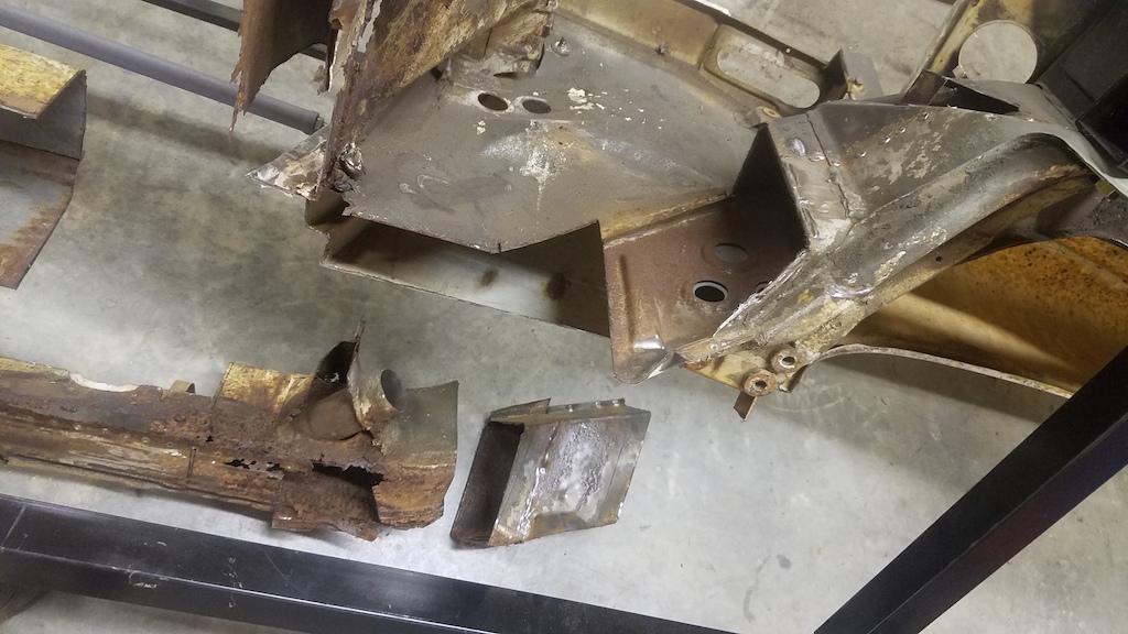
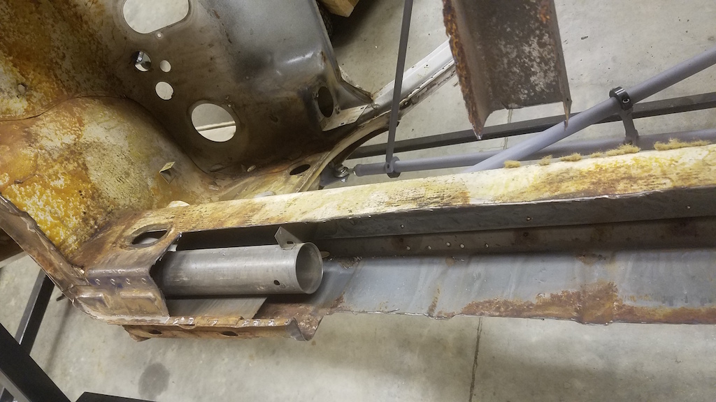
That last picture shows something interesting. There is an internal plate that is sandwiched between longitudinal panels. I'm betting that plate is there to help distribute the load into the long. Extending that plate the length of the long would probably improve chassis stiffness.
I've got a new computer on the way that will handle Solidworks FEA so I will give a shot at testing some of my ideas prior to building it. That new computer will also handle Flow Sim stuff quite well and I've got some wild idea's to try out..
Posted by: 914forme Aug 25 2019, 08:37 AM
If you are not going to use the heater duct for anything take it out, and run a piece front to back up the log as far as you can, out of 16 ro 14 ga. You can get it plasma cut for easy fitment. Makes part of the engmann kit with additional support all the way back.
This is open the inside (cabin side) up to the -4 mount. If you where using a bulk head mount, I would go all the way up the inside to the console.
Great progress way to jump in there, and get it done right!
Match that with the 914ltd kit, on the outside all new metal. That chassis would be strong.
Picture worth a thousand words here. Red is the new piece take all the way up the inner log in to the cabin - to the front.
Black ex is the heater tube too be removed. If you are using them for cooling lines or something else, just use an elbow and come out straight in the flat section of the log.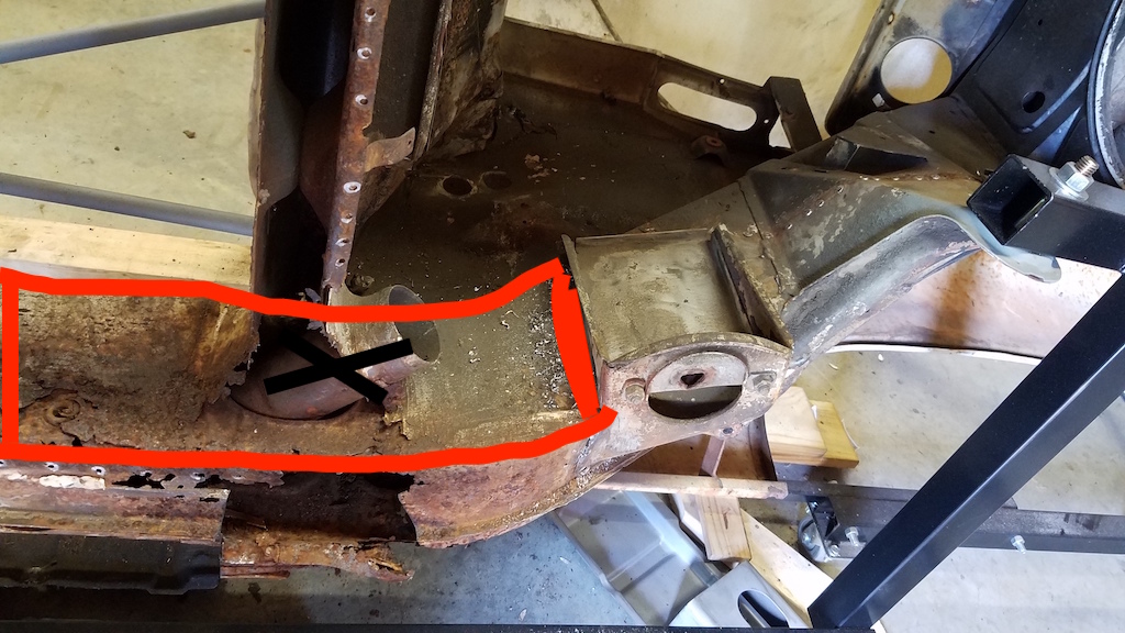
Posted by: 914forme Aug 25 2019, 08:48 AM
Of course you come this far,http://www.tangerineracing.com/chassis.htm.
Inner Console Reinforcements ,and Rear Pickup PointsReinforcing Kit. Both excellent products like all of Chris' stuff is
Posted by: Joemo5 Sep 15 2019, 10:25 PM
@http://www.914world.com/bbs2/index.php?showuser=2388 Thanks for the suggestions! I will likely experiment with various versions of stiffening with the new computer and stress analysis (FEA). It will likely be over engineered but it makes me happy.  Still waiting on the computer to come in.. Lenovo needs to get their act together.
Since the rust extends all the way back to the suspension console and I'm working in the area, I started looking into the raised suspension console option. After some research on the 914 simi trailing arms, I can't convince myself that's the way to go. So.. I'm looking into a 996 suspension swap. The rear has a multi-link setup that looks promising.
I'm picking up Boxster front suspension components tomorrow from the junk yard. Basically whats in the following pic, except for the struts and rack/pinion 
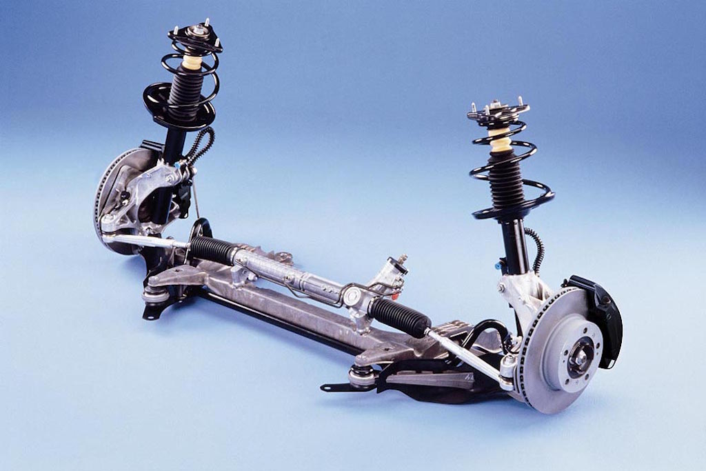
Lots of head scratching ahead of me. Bought some of the best suspension books known to man and will use Optimum K suspension software. 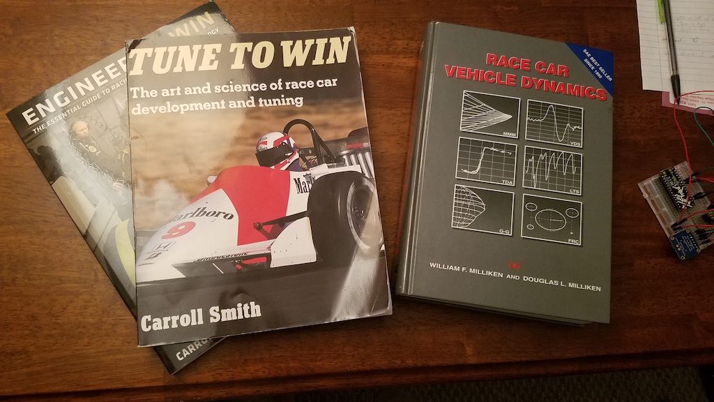
http://www.optimumg.com/software/optimumkinematics/
Posted by: Chris914n6 Sep 16 2019, 12:19 AM
Kool project.
Just wanted to touch base with a few things....
Your board mentions Stand alone ECU, it will need to be able to run Direct Injection. DI injectors are individually tested for flow and resistance and marked. These 2 numbers will need to be entered into the ECU to get the fueling accurate.
Variable output pumps have been around since the 90s. Back then it was 2 stage, normal driving and reduced voltage for quietness at idle. DI has been around in German cars for a decade, but they used normal feed pumps with a pressure regulator built into the assembly to feed a mechanical HP pump. Thus, I think the tightness of PWM is solely for emissions requirements and you should be able to do without as long as it's near the factory specs. The Stand alone can be programmed as needed.
Posted by: jd74914 Sep 16 2019, 05:21 AM
Why OptimumK? Not sure how different the prices are, but if you can get your hands on a copy of Lotus Shark I would definitely recommend going that route. OK isn't super computationally stable (at least the versions that I've used) and sometimes give some really wacky outputs. Just something to watch out for.
I'd also recommend picking up Gilespie's vehicle dynamics book. I've found it to be a bit more feasible than RCVD and it goes into some stuff very applicable to passenger vehicles like suspension loading due to angled axles, etc. which RCVD misses.
Posted by: 914forme Sep 16 2019, 06:10 AM
 Lenovo needs to get their act together
  100%.
100%.
We are now a Dell shop, orders come in on time, I have a dedicated rep, not a rep to my rep. End of October I am going to the Dell logistic center in Nashville to get the final details on our roll out plans done. Zero touch system configuration, we will just hand all new hires and new students a shrink wrapped laptop. Just like you get at the box stores. We touch it for no reason, except for DOA, very small number - normally due to the shipping company running a fork lift thru it. 
Our Dell service rates are at 0.33% across the entire fleet. We are a school, so that number is very low. Our Lenovo fleet was much higher repair rate. One year we had a failure rate of 33% - which meets Critical Situation Levels, nothing from Lenovo for the fix. We ended up fixing them with SSDs retrofitted. Following model from Lenovo only came with SSD or M2 Flash. We are a Lenovo repair center so, we got the money for all the hard drives we replaced. I had boxes of drives in our warehouse waiting to be chipped.
This year we ordered Lenovo Tiny - All - In - Ones, shipments have been back ordered so many times, promised ship dates revised three times now. And they are supposed to be here today, we will see, not holding my breath.
We have watched a steady decline in Lenovo over the last 4-5 years.
YMMV
Neat project, love the idea of Boxster / 996 suspension.
In reality I would go double wishbones up front if I was changing the entire thing out, and spending the time to do all the engineering. But then if using the trailing arms out back it is still a compromise.
Posted by: Joemo5 Sep 16 2019, 08:15 PM
@http://www.914world.com/bbs2/index.php?showuser=431 I'm hoping that by the time I get to setting up the fuel system, Gen V LT chevy swaps are as popular as the LS swaps and there will be lots of info out there on topic if there isn't already. i'm not there yet but you guys are probably right, the PWM fuel pump won't be that hard to get figured out.
@http://www.914world.com/bbs2/index.php?showuser=1659 I'd like to use Optimum K because I have experience with it and know that when working with it to design the SAE Baja car, we barely scratched the surface of what's available. The only downfall is that the free version only lasts 2 weeks and a yearly subscription is like $700. I haven't heard of Lotus Shark but will look into it. Thanks for the Gillespie recommendation.
@http://www.914world.com/bbs2/index.php?showuser=2388 I've had a Lenovo at work for the past 5 years with only one hiccup with a graphics card. Swapped it out for a Quadro P4000 and problem solved. So when looking for computer's I naturally leaned towards what I'm used to. Lenovo also seamed to have the best pricing/spec. I didn't look around too much though.. I did almost choke when I looked up what those BOXX computer's cost.  Ended up with a P320 with an i9-9900, 512g SSD, 16GB DDR4 RAM, and an RTX4000. Should blaze through simulations and run Solidworks with ease
Double A-arm? I like the sounds of that
Posted by: Joemo5 Sep 16 2019, 09:54 PM
Pics of the afore mentioned boxster suspension that I brought home today 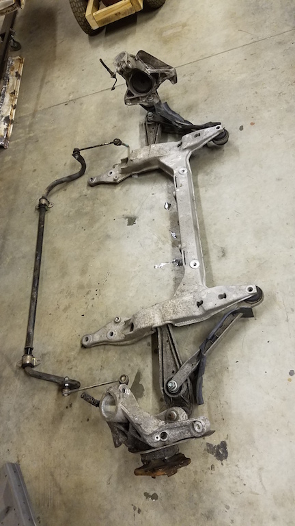
Heres the current idea: Use all of what's pictured but instead of a macpherson strut, convert it to a double A-arm suspension. The top mount for the strut is nothing but a clamping diameter. Fabrication wise, it shouldn't be too hard create an upper ball joint mount out of a chunk of aluminum that fits into that clamping diameter. Extending said chunk of aluminum out the bottom of the clamping diameter should allow attachment of a steering arm that sticks out rearwards and allows the use of the 914 steering rack. Maybe a little far fetched but i think it's feasible.
Since I have both the 914 and boxster suspension sitting in my garage, I weighted them both to get a comparison. I used a bathroom scale so these aren't all that accurate.
914 Suspension including: cross member, control arms, torsion bars, struts, rotors, calipers, hubs, and sway bar
113 lbs
Boxster Suspension including: Everything listed above EXCEPT struts
98lbs
The boxster rotors are really heavy.. like 16.5 lbs heavy.
While we're on this suspension topic.. here's my current plan for the rear suspension. I would like to swap in a suspension that will play well with the front suspension that I have chosen. The boxster, cayman and 996 all have front suspensions that are very similar. The 996 however, has a multilink rear suspension that looks like it would fit very well into the rear of a 914. Here's a google pic for reference: 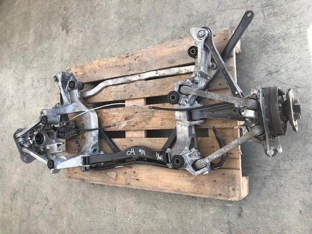
Use your imagination here.. take the above components, build a rear subframe that houses the engine and transmission. Wouldn't look identical but heres another picture for reference. 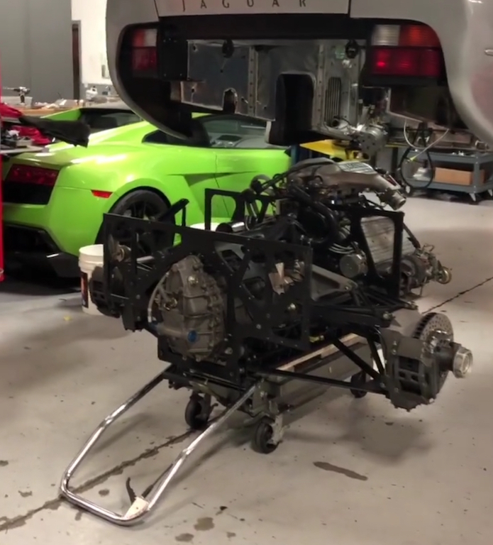
I'm definitely headed down a path of unknowns. it will be hard to put my thumbs on exactly what modifications need to be done before taking accurate measurements and putting it in optimum K. Ideally the rear would be a direct swap in and then alter the front double A-arm's until there's an acceptable roll axis and camber curves. The 996 rear suspension is likely catered for the rear engine and higher polar moment of inertia so there's that to deal with..
Why do I want to go down this path?
- My boxster S calipers are a direct fit to the boxster knuckles and should be to the 996 knuckles
- No compromised trailing arm geometry
- 4 corner wheel speed sensors (lots of options: ABS, traction control, etc)
- An off the shelf axle may work with my G86.20 trans: more research needed
- Off the shelf boxster/996 rotors and pads
- Use of this: https://www.jrishocks.com/shop/specialty/hydraulic-ride-height/
Posted by: dakotaewing Sep 16 2019, 09:55 PM
Great project! I'm kind of in a similar spot in my project, but it has been that way for years.
My only suggestion looking at your chassis would be to go ahead and get it soda blasted, and epoxy primer'd now.
It will expose anything hidden that you might not see other wise,
and will also save you the time of mechanically removing paint otherwise.
Posted by: Joemo5 Oct 5 2019, 07:39 PM
Great project! I'm kind of in a similar spot in my project, but it has been that way for years.
My only suggestion looking at your chassis would be to go ahead and get it soda blasted, and epoxy primer'd now.
It will expose anything hidden that you might not see other wise,
and will also save you the time of mechanically removing paint otherwise.
Yeahh, I would like to get it blasted. However every different option seams to have it's draw backs. Soda has to be neutralized, sand stays in cracks forever, dips remove paint in between pinch welds.. I haven't decided yet. My plan is to fix to replace the worst sections, then move on to the smaller rust issues, including blasting.
Posted by: mepstein Oct 5 2019, 07:51 PM
Plastic bead blasting with garnet on the rusty spots.
Posted by: Joemo5 Oct 5 2019, 09:24 PM
So I've been having some fun. I started breaking down the boxster suspension. Here's a pic pressing out the bearing. Those things were in there!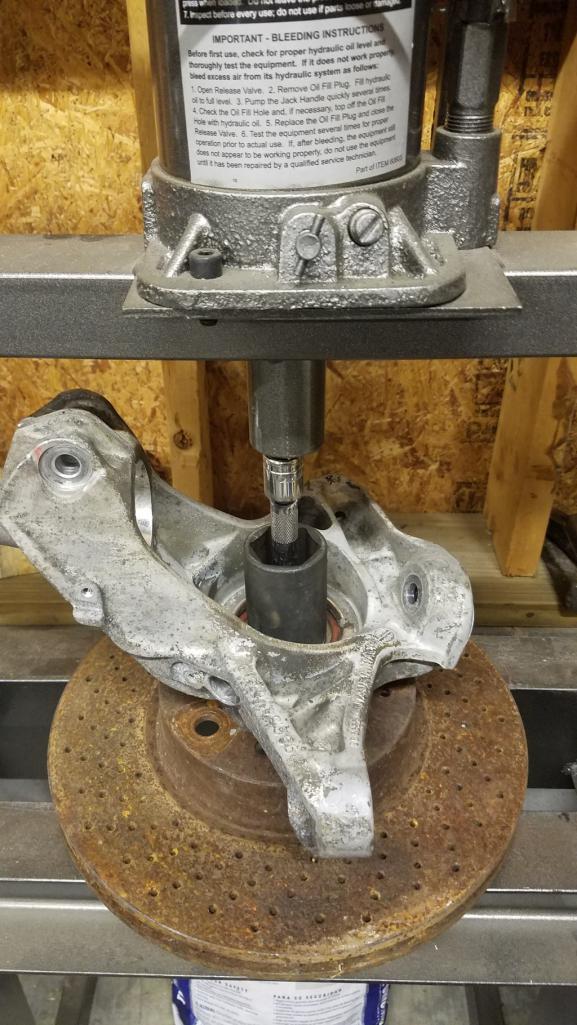
I was going to start attempting to model some of the important points in Solidworks and then remembered reading an article about photogrammetry and how it's possible to obtain 3D data from pictures. So I gave it a whirl and I am freaking mind blown. I used my samsung S7 camera (cell phone) on the auto settings and a really basic setup to suspend the knuckle from strings.
Here's the physical setup.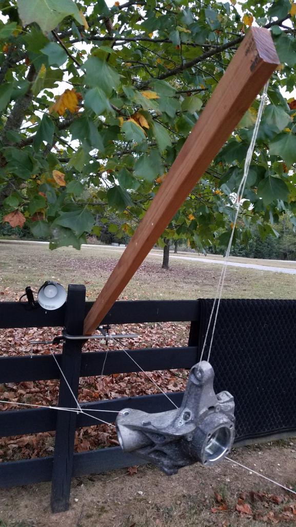
I took 219 picture at a multitude of angles. I did no editing of the pictures and uploaded them into RealityCapture. A few clicks later, about 10 minutes of processing time and NO cleanup this is what it generated.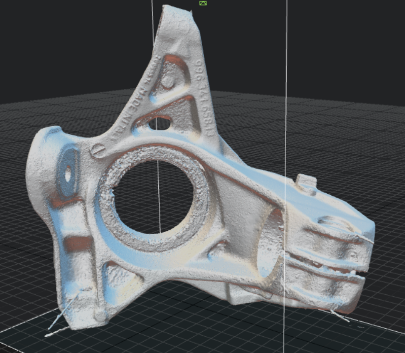
Here's a video flipping the mesh around
https://www.youtube.com/watch?v=SJXa_tz24t4
i am beyond stoked! This is more than good enough to cleanup and retain a reasonable accuracy for modeling purposes. I'm still learning how to cleanup the mesh and manage the file size. However, this took maybe 4 hours, including learning everything for the first time. I could likely repeat this process in less than an hour for a new part. The idea here is that this will vastly speed up my process to design a custom front dual A-arm suspension. What a time to be alive..
Posted by: Joemo5 Oct 7 2019, 08:22 PM
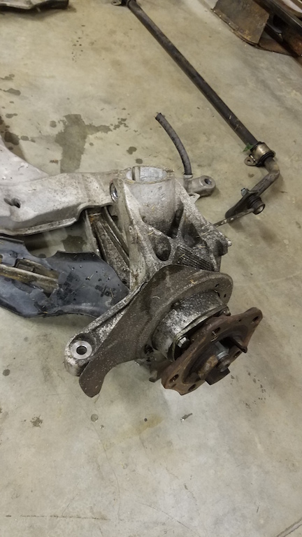
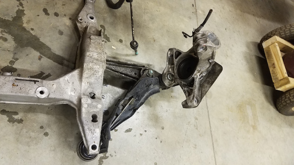
Dad and I drove to Tennessee yesterday and picked up the rear suspension out of a 996 C2. Made for about 12 hours of driving in one day but it was a killer deal. Here's what we brought home. 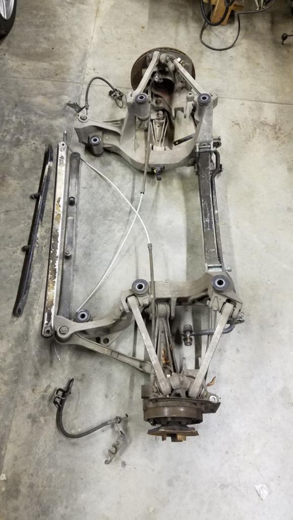
I took a few pictures of the mounting points on the 996 and was pondering the best way to mount it to the 914. The 996 has studs that stick down. I'm thinking the mounting points will be inboard of the 914 frame rails. 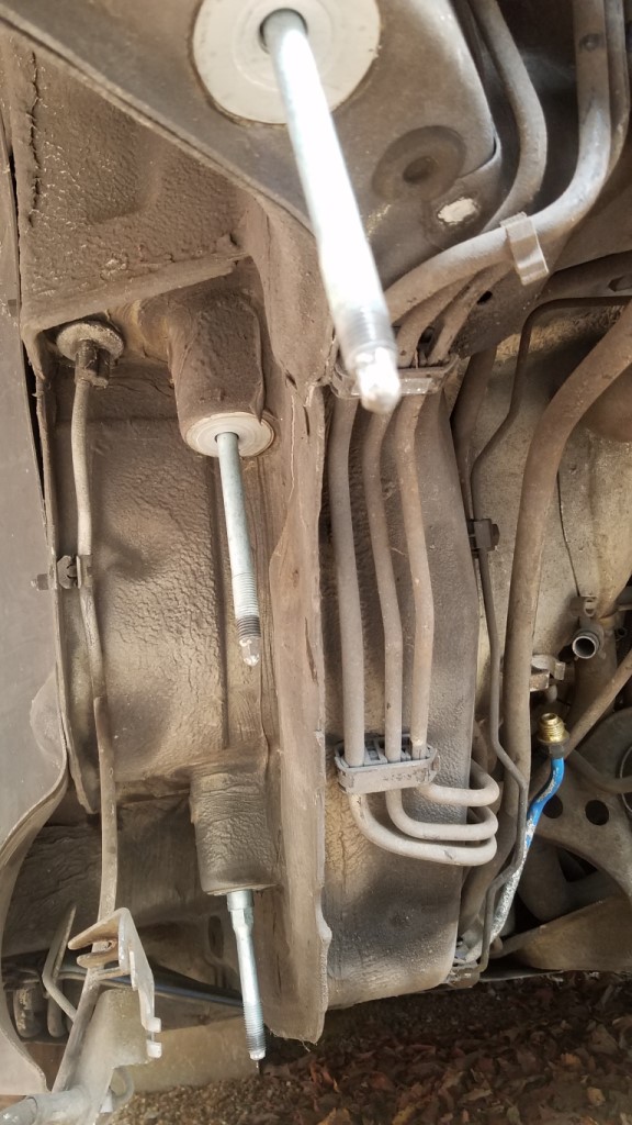
Along the same lines, I tossed the Boxster K-member on the bottom of the car to get an idea of where the mounting points fell. 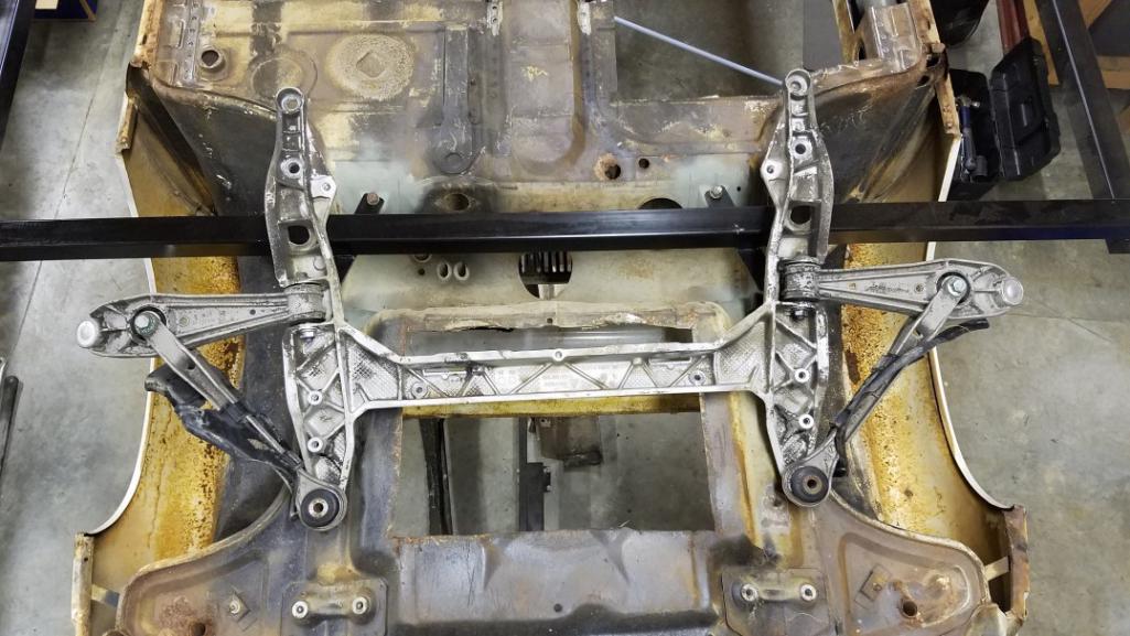
Posted by: cooler Feb 6 2021, 10:47 PM
I love this! Please continue!
Powered by Invision Power Board (http://www.invisionboard.com)
© Invision Power Services (http://www.invisionpower.com)