Printable Version of Topic
Click here to view this topic in its original format
914World.com _ 914World Garage _ Charging question on a 914-6
Posted by: db9146 Jul 28 2018, 08:11 PM
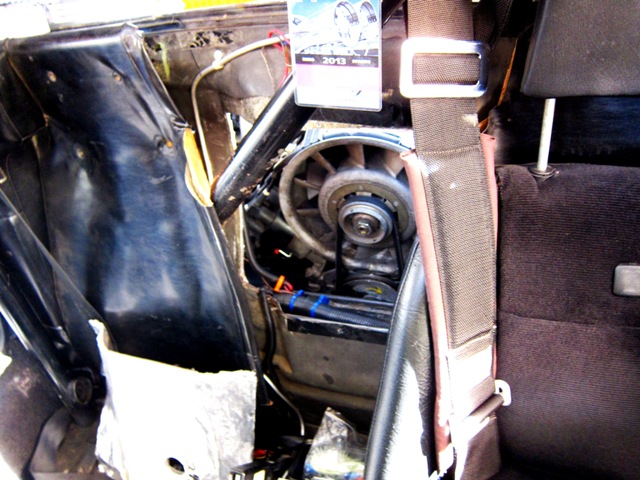
Well, I have made a temporary conversion of my -6, inserting a rebuilt 2.7S with ITBs, MS3, and distributorless ignition in place of the tired 2.0L. Before putting the engine in, I decided it best to install a new alternator along with a new engine/alternator wiring harness.
The alternator is for a 1965-1977 911 2.0-2.7 that uses an external VR.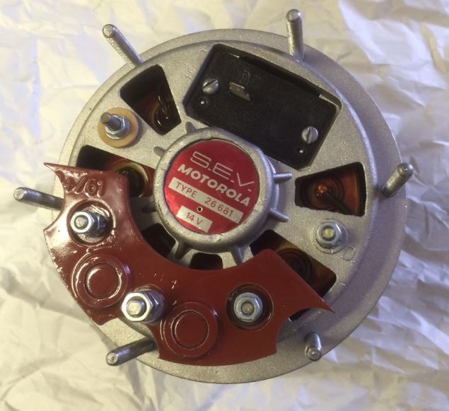
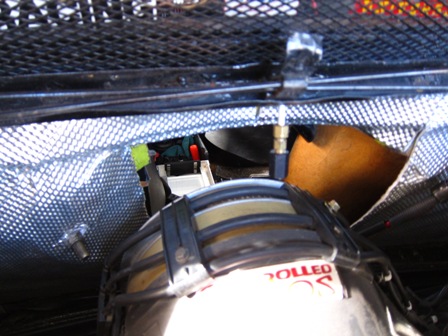
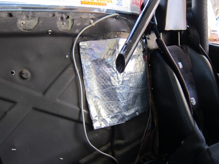
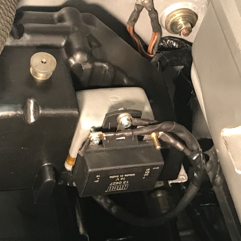
and here's the new wiring including a new ground strap to the engine case.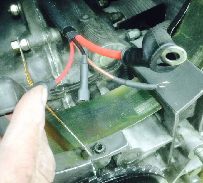
The large red cable goes to the starter, the smaller red wire is D+, the black is DF, and brown is D-.
I thought the problem might be the battery because of its age but when I checked the output of the charging system at the battery, there was none. I replaced some of the dash lights with LEDs but made sure not to replace the GEN warning light, which is not coming on despite the alternator not charging.
Should I next pull the D+, DF, and D- plug and check for alternator output across DF and D+ momentarily?
If there is output, what then?
If not, what's next?
Posted by: larryM Jul 28 2018, 10:48 PM
see my updated notes with pics below
http://www.914world.com/bbs2/index.php?showtopic=327218
http://www.pelicanparts.com/techarticles/101_Projects_Porsche_911/20-Alternator_Replacement/20-Alternator_Replacement.htm
http://nodasystech.com/design/porsche-911-alternator-wiring-diagram.php
http://www.aa1car.com/electrical.htm
http://easyautodiagnostics.com/misc-index/how-to-test-a-bad-alternator-1
Posted by: db9146 Jul 30 2018, 08:51 AM
Thanks Larry.
I hate electrical issues.....
Okay, the GEN light was on with the key on, and off as soon as I started the car yet when I checked the battery charging, the battery voltage was unchanged with the engine running at a fast idle.
So I swapped the VR and tried again. I am now seeing a voltage increase to 13.14.... better but still not what you would expect. I'm measuring with a multimeter across the terminals with the engine at about 1800-2000.
The harness from the new alternator to the starter motor and from the starter to the battery is all new and built from one of Perry Kiehl's kits, so its all properly sized. I installed new braided grounds at the alternator, the trans, and the battery. I've checked the battery and trans and they're tight. I remember distinctly tightening the strap on the alternator to engine case (and oriented it so it would foul anything). I did paint the trans but I can't believe that would be an issue with a new braided cable and hardware.
Any other ideas to consider to improve the low charging voltage?
Posted by: SirAndy Jul 30 2018, 11:33 AM
How exactly are you testing the output?
I know at least on my /6, i have to blip the throttle to get the engine over 2k+ rpm after i start it for the alternator to kick in and produce current.
If i just let it idle, it won't charge and the warning light stays on.
I've been told that this is somewhat normal ...

Posted by: db9146 Jul 31 2018, 12:39 PM
Last night, I measured the voltage at the battery again with it fully charged before I started. It was 12.8V. I turned the key (GEN light came on), then started it up (rev'ed it and GEN light went off) and measured the voltage at the battery again - no change.
I then replaced the VR with a "new" old VR that I just recently bought and measured the voltage again. This time it was about 13.15 at an elevated idle. So now it seems like its charging but not much, so I checked the chassis strap to the trans.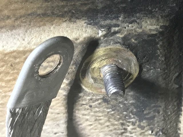
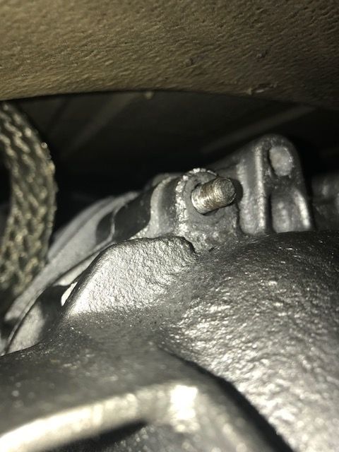
I removed the nuts and strap, checked that the area was as clean as I thought, and reattached the new strap in between.
I then moved to the ground strap connection for the battery. Before I installed the new engine, I repaired the ground stud which the PO had twisted off, cleaned up the area, and installed the new battery ground strap. Everything looked good and was tight here.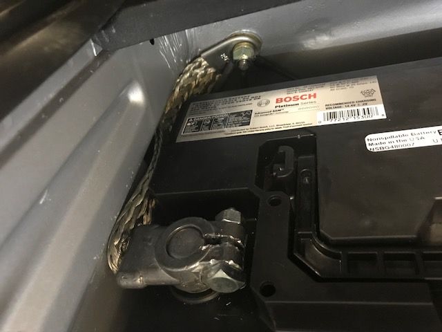
Even with this, I checked the battery voltage again and got 13.10, slightly less than I had measured before removing, checking, and reinstalling the trans ground strap.
Posted by: Mark Henry Jul 31 2018, 01:06 PM

Last night, I measured the voltage at the battery again with it fully charged before I started. It was 12.8V. I turned the key (GEN light came on), then started it up (rev'ed it and GEN light went off) and measured the voltage at the battery again - no change.
I then replaced the VR with a "new" old VR that I just recently bought and measured the voltage again. This time it was about 13.15 at an elevated idle. So now it seems like its charging but not much, so I checked the chassis strap to the trans.
Like Andy said you may have to take a speed run well over 3000rpm. The 13.15 is likely good, a points style regulator the voltage will fluctuate at least half a volt.
Do you have a gel cell battery? They always seem low compared to a wet cell.
The 12.8v fully charged could be perfectly normal if it's a gel cell like an optima.
Posted by: Spoke Jul 31 2018, 01:29 PM
If GEN light is on when key is ON and engine not started, then goes off, it sounds like the alternator is working.
Posted by: db9146 Jul 31 2018, 02:35 PM
MH and Spoke, I had started my last post earlier this afternoon and got interrupted by work....go figure.
Anyway, I did install a new Bosch AGM battery so these measurements are with it. The VR is an NOS Bosch metal can unit but I'm seriously contemplating a new SS one or even one of the variable VRs but I want to determine that everything is really okay before I go to an adjustable VR and cover up the symptom (lower charging voltage).
Posted by: db9146 Jul 31 2018, 05:23 PM
This is getting screwier by the moment......at least in my mind.
Tonight, before I started the engine, I measured battery voltage (new Bosch AGM, Group 48)...it was 13.11. Then I started the engine and idled it up, turned on the headlights and measured again....12.89. Turned the lights off, measured again...12.88. Hmmmmm.
I was about to pull the VR and jumper between DF and D+ when I jumped over and read this doc. (http://www.ratwell.com/technical/ChargingSystem.html#vrtest) on charging system testing. In it, it specifically states not to run this test as it can damage sensitive electronics such as ECUs!!! I''m running MS3x so I'm glad I read that...whew. But I did figure out a way to get a measurement at D+ below.
In the same doc, it gave measurements for ohms across, D+, D-, and DF terminals of the VR: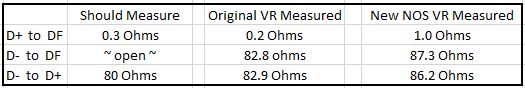
Next, I checked the alternator harness since I had built it new when I installed the new alternator in the engine last year. It checked out fine as well. Then, with the engine running, I pulled the alternator 3-pin connector loose from the circuit board just enough that I could get a multimeter probe under the connector housing and touch the spades for a direct measurement.
On the D+ pin at idle, I measured 13.7V. On the DF connector at idle (750 RPM), I measured a stable 7.4V, But when I idled up the engine to about 1800-2000, I measured the same 13.7V on the D+ pin and an erratic 3.7 - 4.? on the DF pin.
I believe the D+ pin should be reading the full output of the alternator before the voltage regulator, should it not? If so, then why was I only getting 13.7V? Shouldn't the reading have been closer to 15-16V?
Posted by: db9146 Jul 31 2018, 08:43 PM
You can also measure the unregulated output of the alternator by measuring between the lug on the starter where the B+ cable connects and a ground point, correct?
Posted by: Mark Henry Aug 1 2018, 09:54 AM
Is this alternator out of a 911 with the dual batteries?
IIRC the alternator for this has a lower output voltage, something to do with the dual batteries not being able to handle higher charging volts. So this could be normal for this alternator.
I don't have time to search this, but I'd check it out.
Posted by: Spoke Aug 1 2018, 10:32 AM
On the D+ pin at idle, I measured 13.7V. On the DF connector at idle (750 RPM), I measured a stable 7.4V, But when I idled up the engine to about 1800-2000, I measured the same 13.7V on the D+ pin and an erratic 3.7 - 4.? on the DF pin.
I believe the D+ pin should be reading the full output of the alternator before the voltage regulator, should it not? If so, then why was I only getting 13.7V? Shouldn't the reading have been closer to 15-16V?
In the above measurements, I assume the VR was still operating in the system.
The D+ pin is the output of the alternator to the VR. The VR will vary the voltage on pin DF based on the voltage it sees at D+. The VR will try to keep D+ in and around 13.5V or so, exactly what you are measuring. It will regulate D+ using DF to vary the magnetic field in the armature (rotating part of the alternator).
As far as the erratic voltage at D+ when the engine RPM are up, this could just be the normal regulation of the VR. As the engine RPMs increase, so does the output of the alternator increase. The VR will likely lower DF to maintain 13.5V or so at D+. If a voltage is moving around quickly, a DVM is not so useful and an oscilloscope is needed to be able to "watch" the voltage fluctuate.
D+ will only be 15-16V when D+ is shorted to DF as the alternator will be producing maximum voltage.
Posted by: db9146 Aug 2 2018, 09:03 PM
MH, the engine is from a ‘74 911S but I’m not aware if they had dual batteries.
Spoke, thanks for the explanation. I understand what you have explained but I guess my only remaining question is: if the alternator was generating 13.7V, then why wasn’t I measuring 13.7V at the battery? I have always thought that measuring voltage across the terminals of the battery with the engine running was a measurement of the regulated output of the alternator. That’s why I was thinking that I had a charging problem. (BTW, I’ve got a full set of your front and rear LED lights. I love ‘em.)
I have a new SS, adjustable VR on the way and will see if that makes a difference in the charging measured at the battery.
Posted by: 914Sixer Aug 2 2018, 09:18 PM
74 911 was a single battery.
Posted by: db9146 Aug 12 2018, 05:08 PM
Does anyone know the wattage of the light bulb in the combo gauge that tickles the alternator to start working? I need to confirm I have the right one....still chasing an issue and Okteenerfest is fast approaching.
Is there a specific wattage or just any incandescent 12V bulb?
Posted by: larryM Aug 13 2018, 09:03 PM
you wrote above: "the GEN warning light, ... is not coming ON"
if it is never ON, then you are not getting 12v field exciter current to the regulator
- your initial problem is to get juice to & thru that bulb & to the VR so that the VR can energize the alt field
"2-3 watt bulb is enough for normal alternator excitation." Scroll to page 20 of this > https://woodmizer.com/us/portals/0/docs/743d8322-c451-4676-8e08-89c0c8e77ef1.pdf
iGN ON (not running) - measure the voltage on the (blue) wire which should be attached to that bulb - where it connects to your relay panel - so you know if you have current twixt the ign sw & thru the bulb to the next potential roadblock item (the panel) - if ya got 12v there,
if you ground that wire the bulb should light, which tells ya circuit is active to that point
then see if you have 12v at the VR plug (color of wire is different after it leaves the panel) - if ya got 12v all the way to the VR, (and you already tried a new VR) then your alt field is not energizing, thus no output
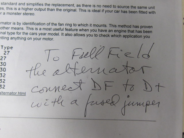
you should read 12V at field wire DF - if you then jumper DF to D+ with a fused jumper, (engine running) you should get full alternator output - if no 12V at VR DF with ign on, then your problem is upstream, either a bad regulator or bad wiring to dash & ign
OR - possible bad alt or incorrectly wired at the back of alt
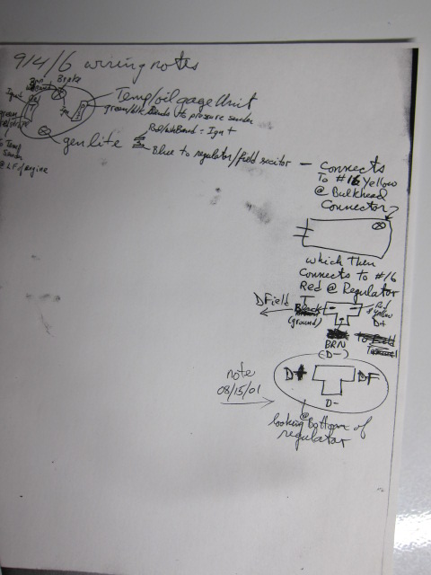
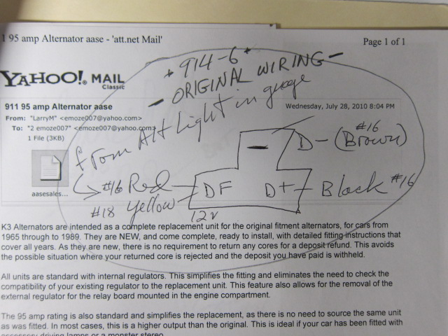
here are pics of some notes from back in 2009-10 when i had a similar problem (difference: my -6gt- never had a relay panel) 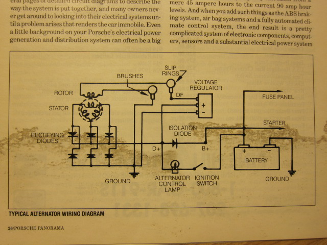
Posted by: porschetub Aug 14 2018, 02:20 PM
Thanks Larry.
I hate electrical issues.....
Okay, the GEN light was on with the key on, and off as soon as I started the car yet when I checked the battery charging, the battery voltage was unchanged with the engine running at a fast idle.
So I swapped the VR and tried again. I am now seeing a voltage increase to 13.14.... better but still not what you would expect. I'm measuring with a multimeter across the terminals with the engine at about 1800-2000.
The harness from the new alternator to the starter motor and from the starter to the battery is all new and built from one of Perry Kiehl's kits, so its all properly sized. I installed new braided grounds at the alternator, the trans, and the battery. I've checked the battery and trans and they're tight. I remember distinctly tightening the strap on the alternator to engine case (and oriented it so it would foul anything). I did paint the trans but I can't believe that would be an issue with a new braided cable and hardware.
Any other ideas to consider to improve the low charging voltage?
Interesting reading as I have the same issue almost exactly,same new parts even,rebuilt altenator,new loom,new NLA regulator,repaired relay board and new ground leads, I haven't done the relay jumper as yet as spoke mentioned and that will be my final attempt before pulling the altenator,I have a small GSM battery and someone mentioned funny things can happen with these...I just don't know.
Posted by: Spoke Aug 14 2018, 02:39 PM
So I swapped the VR and tried again. I am now seeing a voltage increase to 13.14.... better but still not what you would expect. I'm measuring with a multimeter across the terminals with the engine at about 1800-2000.
I recently checked my 930 battery voltage it wasn't much different from your 13.14V. I was surprised it was that low but I haven't had trouble with the charging system.
If the battery voltage is over 12.6V when running then the battery is being charged. If you have trouble starting the car then maybe more attention to the charging system is needed.
Posted by: db9146 Aug 14 2018, 07:38 PM
LarryM,
Thanks for the great additional info!!! Saved it for reference.
Tonight I checked and:
- I have a 12V 2W Osram buld in the GEN socket
- it lights when I turn the ignition on
- it goes out a moment or two after the engine starts up
- I get 12.5V at the dash light
- 12.5V at the D+ female on the circuit board that the VR plugs into
- 12.5V at the D+ male spade on the circuit board that the plug from the Alt. connects to
- and 12.5 at the DF male spade on the circuit board that the plug from the Alt. connects to.
LarryM, you mentioned that the issue may be upstream in the wiring at the dash or ignition switch. If I'm getting 12V at the GEN bulb and D+ on the circuit board, wouldn't that indicate that the wiring between the circuit board, dash, and ignition switch is okay?
I understand that the next step is to try to measure the full alternator output by jumping DF to D+ but I really don't want to do this because the new engine is running individual throttle-bodies and MS3x. (CAUTION: Voltage is unregulated during this test and could damage sensitive electronics. {http://bronek.org/sailing/zamindar/resources/Alternator-regulator%20troubleshooting.pdf}). I think that means that I could kill my ECU.
It seems I really need to find another way to test the alternator.
NOTE: Before trying to perform the full field testing, I read that one common way to test modern alternators is to test for a magnetic field with a screwdriver once the switch is turned to the "on" position. However, I don't this will work on a Porsche -6 since it relies on the bulb to provide the resistance to "tickle" the alternator into charging.
(Man I don't want to drop the engine for this....)
Posted by: db9146 Aug 14 2018, 08:09 PM
If the battery voltage is over 12.6V when running then the battery is being charged.
Spoke, why would you say that the battery is being charged at only 12.6V measured voltage at the battery with the engine running? I have always seen a figure between 13.6 and 14.4 as the output for a properly operating alternator. And yet, a couple weeks ago I took the car out for a drive in the evening and had the lights on. I stopped and had to get a jump to get the car started again. In talking with a friend this morning, he commented that if the old battery was so dead that it wouldn't start the car and then it ran fine the entire way home after a quick jump, that the alternator must be putting out some power just to run the engine and lights on the way home....a simple jump would not have provided the juice necessary for that.
So honestly, I am coming back to your comment and wondering if the new battery I installed and checking of all of the grounds didn't fix the problem....and I'll just have to adjust to a new "normal" charging voltage. I really can't think of another way to test the alternator output if I can't perform the full field test for damaging the ECU.
Posted by: Spoke Aug 14 2018, 08:43 PM
If the battery voltage is over 12.6V when running then the battery is being charged.
Spoke, why would you say that the battery is being charged at only 12.6V measured voltage at the battery with the engine running? I have always seen a figure between 13.6 and 14.4 as the output for a properly operating alternator.
The resting voltage of a battery is 12.6V. Anything higher than that indicates the battery is being charged. I just checked the battery voltage of my '86 930
when idling and revving to about 2500RPM and the battery voltage only increased to about 13.5V. I wasn't expecting the voltage to be that low but on the other hand I've never had an issue with starting or operating the car.
Likewise about the 13.6-14.4V as the output being standard. My 914 does just under 14V at most all RPM. Not sure why the 930 is lower. It hasn't caused a no-start issue or running issue so I'll let it go for now.
Posted by: db9146 Aug 15 2018, 09:51 AM
Spoke, I just updated my previous post. I agree with your comments above but my issue is that I never see a charging voltage above 13V now. I think when I saw those measurements, they were battery voltage of a brand new battery and now that I have run it some, I'm not seeing 13V. I'm also leaving it off the trickle charger in between occasional evening drives to check the battery/voltage in an "unsupported" environment.
Posted by: larryM Aug 15 2018, 09:22 PM
If I'm getting 12V at the GEN bulb and D+ on the circuit board, wouldn't that indicate that the wiring between the circuit board, dash, and ignition switch is okay?
NOTE: Before trying to perform the full field testing, I read that one common way to test modern alternators is to test for a magnetic field with a screwdriver once the switch is turned to the "on" position. However, I don't this will work on a Porsche -6 since it relies on the bulb to provide the resistance to "tickle" the alternator into charging.
(Man I don't want to drop the engine for this....)
- if light goes out on start, and you have battery volts at DF with ign ON not running, then "upstream" is all OK - the VR should be sending a signal to energize the field - ya gotta hope that field wire is attached correctly at the alternator
i agree with your observation to Spoke about charging volts - "... minimum charging voltage is 13.8 volts dc across the battery terminals, or at the output of the alternator. A single lead-acid cell starts to charge at anything over 2.25 volts. Since a 12 volt battery has six cells, any 12 volt lead-acid battery needs at least 13.8 volts to start to charge. Testing battery and charging system - W8JI.com https://www.w8ji.com/battery_and_charging_system.htm
- and if you turn on all the lights & loads it should kick up even higher, but will be regulated to 14.2-14.5 if your VR is good ... "To fully charge in reasonable times, alternator output must be 14.2 V to 14.5 V as measured right across the battery posts" (ibid)
various sources will say "13.2-14.8" is the output range ( or more typically 13.8-14.2 means OK alternator)
dunno about that magnet theory - (never heard that one before) where would you stick the screwdriver? - no way you can put it next to the alternator buried under the shroud - you might wanna test that idea on a different alternator on the bench
engine drop - that's why our GT cars had a porthole in the back firewall - i have had alt out & back in thru that porthole several times over 25 yrs -
it also makes timing & distributor & belt maintenance MUCH easier
- i did enlarge my factory porthole a bit to make it easier the second time when the new IR Valeo 95-amp came with incorrect wiring diagram & I had exactly the problem you seem to be experiencing)
 .... 2-days work cuz a vendor screwed up
you might consider cutting one in - your car is enuf modified now that "originality" should not be a concern
i think one of our vendors now sells a fiberglass cover for it, so you can use it for a pattern - (or i likely have an oem paper pattern stashed somewhere & could send it to you)

Posted by: larryM Aug 15 2018, 09:39 PM
p.s. - long ago i acquired some 911 engines & -6 stuff where the p.o. solved the 'engine drop" problem by cutting a large hole in the back of the shroud so he could get at the alternator wires - then he just made a nice grommeted rectangular patch & screwed it over the hole
(depends on how desperate one is & how much time & what shop resources one has, eh?)
i eventually threw that shroud away but i did keep the air duct for the oil cooler (3.2 has a removable duct which makes things much easier)
Posted by: larryM Aug 19 2018, 10:29 AM
given everything you have reported above - consider DD's idea of bad diodes
6. Check for Alternator AC Voltage Leak
Alternators use diodes to rectify alternating current produced by the alternator into direct current. When one or more diodes go bad, the alternator can cause all kinds of problems. AC voltage leak can cause your lights to dim and drain power from your battery, for example. Usually, you can detect this leak by measuring AC voltage across the battery posts using a digital multimeter.
Start and let the engine idle.
Set the parking brake and your transmission to Park (automatic) or Neutral (manual).
Set your meter to a low AC voltage range and take your measurement.
If you detect even a small amount of AC voltage, replace the alternator.
Once you've determined the condition of the system, you can go over the next section to zero in on the potential problem(s) that may be causing the condition of the charging system.
https://axleaddict.com/auto-repair/Alternator-Problems-Troubleshooting
then see -
IV. Troubleshooting for Unusual Charging System Voltage Drops
Posted by: db9146 Sep 6 2018, 01:50 PM
Well, I spent last week dropping the engine and addressing several items I had noticed, including pulling the alternator and having it checked. The local auto electrical shop put it on his bench tester, spun it up and said "so its 55 amp unit, huh?" so it checked out okay. I double checked the wiring, fan belt, etc. as it was going back in.
Everything seems to be the same as it was before I pulled the engine. All the connections are good, dash light working as it should, traced the 12v through the circuits following the info posted (thanks again, LarryM), and swapped to a different VR. Getting 13.1 to 13.2V at the battery with it running. Not really any different before dropping the engine other than knowing that the alternator is working and the connections are good (even pulled the grommet out from around the large cable to the starter/battery from the shroud enough that I could check the back of the alternator once it was back in the engine....once I remembered I had a tiny camera to check it with....doh).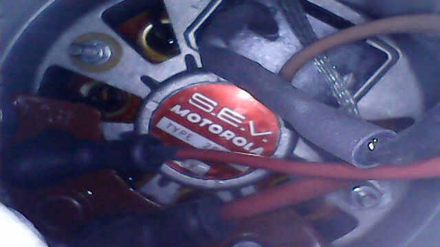
I also managed to seal a small oil leak, a small exhaust leak, clean up the underside of the car a little more, and install a new muffler so I guess it wasn't all for naught. I just really wish I could get the charging voltage up a bit. I may try a variable VR and see if that has any effect.
You know, thinking about the VR, the external VR for a 911S looks like this:
I wonder if even though the wiring is the same, there is some difference in the settings within the VR that is causing the output to be so low. The whole time I had the original engine in the car, I never checked the charging voltage. The original 2.0L -6 is a 911T engine I understand so you would think that the stock -6 VR would work fine with any other 911 engine with an external regulator, right?
Posted by: larryM Sep 8 2018, 09:50 PM
I wonder if even though the wiring is the same, there is some difference in the settings within the VR that is causing the output to be so low. ........... you would think that the stock -6 VR would work fine with any other 911 engine with an external regulator, right?
all the same - - all regulators are "variable" - they deliver to load demand
Part Number: 901.603.206.01
Brand: Bosch
Model: 911, 912E, 914
Year: 1965-1976
your post #5 above said ... "It was 12.8V. I turned the key (GEN light came on), then started it up (rev'ed it and GEN light went off) and measured the voltage at the battery again - no change."
therefore you have improved something, since you are now getting 13.2 which is in the "normal range" vs the 12.8 previous readings
13.2 V at what rpm?
and with what loads being drawn?
turn on everything electric, run 2000+ rpm, & see if it kicks up higher volts - it should
BUT- if the volts drop lower than 13.2 via that simple test, it ain't chargin' right
Posted by: db9146 Sep 11 2018, 07:39 AM
Well, I think I figured it out.
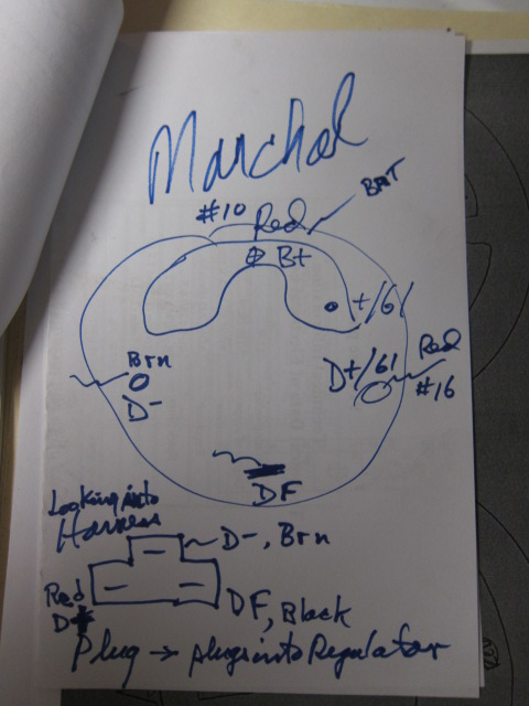
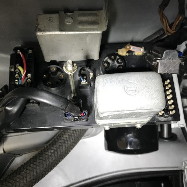
All 914-6s were set up for the Bosch style VRs which work with the Bosch externally regulated alternators in the stock 2.0L engines. The Bosch VR's housing fits nicely onto the stock -6 relay board. However, if you switch engines to a larger -6 that has an externally regulated SEV Marchal alternator like the one in my new engine, you can't use a Bosch VR.....you have to wire in an SEV Marchal regulator. This was my solution to get my charging system to work properly after installing a '74 911S 2.7L in my 914-6.
I actually gutted an old Bosch VR and made up a small harness that could plug into the stock relay board connector under the VR but then it exits through the rectangular hole in the relay and wraps back up to make the connections on the new SEV Marchal VR. Doing it this way keeps any water out of the relay board connector under the Bosch VR.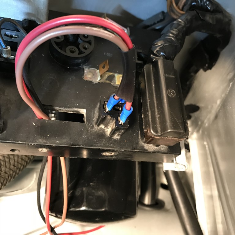
Frankly, I can't explain the difference, however, I can state my observations.
1) There is a label on the underside of the deck lid on an original 914-6 that states that you must match the manufacturer of the VF and alternator. Originally, my -6 had a Bosch alternator and a Bosch VR. When I installed the newly rebuilt 2.7 (which also had ITBs, Megasquirt, and distributorless ignition), I replaced the SEV Marchal alternator with a rebuilt one to avoid a problem down the road. I bought the SEV Marchal unit because I knew it would fit in the fan/fan housing. This is when my charging issue began. I could never get the new alternator to charge the new battery, despite chasing all of the connections and voltages. I could never find the problem.
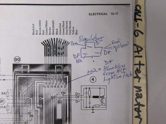
2) I then started my search and when looking at the Pelican Parts website for a '74 911S (the car my new engine came from), PP had a Bosch VR listed but also a separate call-out for an SEV Marchal unit. If they list two different VRs for the same car, then maybe there is some difference that I don't fully understand. I believe the diagrams above point to that difference but I am not an electrical engineer and I haven't taken the time to study this difference until I understood it, but only to the point to recognize that there is a difference.
3) Last night after installing the SEV Marchal VR, I was able to get 13.5 - 13.6 volts indicated at the battery for the first time since discovering the problem (  ). I know that this is not the 13.8-14.6 that is typically expected with other cars but it is in line with others who have posted about the charging voltages they have measured at the battery on other 911s/930s, including our own Spoke above..
So, while I can't state an explanation in specific terms, I have stepped through the problem in a logical manner (I believe), noted my observations along the way, and come to a satisfactory solution that I'm happy with.
There is another similar thread I joined in on over on the PP board here that has some diagrams https://forums.pelicanparts.com/porsche-911-technical-forum/1006571-alternator-problems.html which explain the differences between the Bosch system (alt. and VR) and the SEV Marchal system.
LarryM, thanks again for all the help figuring this out, for the posts you added, and for the IMs as well! 
Posted by: FlacaProductions Sep 11 2018, 09:15 AM
Just read this whole thread and I love it when a logical, thoughtful troubleshooting procedure ends with success. Nice work and good reference info for others in the future.
Posted by: ClayPerrine Sep 11 2018, 10:20 AM
There is a SEV Marchal Voltage regulator that plugs into the relay board. I ran one with my 73 911 engine for years.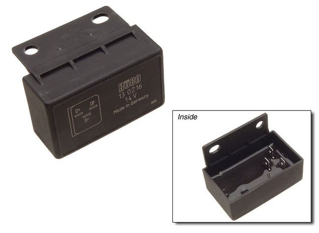
Worked fine with a stock six relay board.
Powered by Invision Power Board (http://www.invisionboard.com)
© Invision Power Services (http://www.invisionpower.com)