Printable Version of Topic
Click here to view this topic in its original format
914World.com _ 914World Garage _ 1973 2.0L Rustoration
Posted by: Superhawk996 Dec 21 2018, 04:10 PM
I purchased my first 914 back in 1987 (1973 1.7L) and had that car for nearly a decade and I personally put over 100,000 miles on it before it ultimately fell victim to a negligent driver that drove into the back end of it at about 40 mph while the vehicle was stopped at a red light. That rear end crash totaled the vehicle but what is amazing is how well it crumpled (early crush zones!) due to the kink in the frame where the halfshafts are. Everyone walked away unharmed.
I replaced it with a 1991 Miata. Great car in its own right but I've always missed my 914.
Purchased this "replacement" in May 2018 as a known poster child for a complete right side longitudinal rustoration.
This vehicle had been put into storage inside a pole barn around 2004 as far as I can tell.
Vehicle initially purchased in non-running condition:
Engine couldn't be started.
Transmission shift linkage was disconnected
Half shafts and CV's were in pieces, and the wheel stubs were not installed therefore the vehicle couldn't even be rolled without risking having the rear wheel separate from within the bearing.
Fiberglass laid into the floorpan . . . that can't be a good sign.
Vehicle looks great . . . until I got under it.
I spent the better part of the summer putting the items above back together and trying to confirm that it would:
1) Run under its own power
2) Drive though the neighborhood and shift though all gears.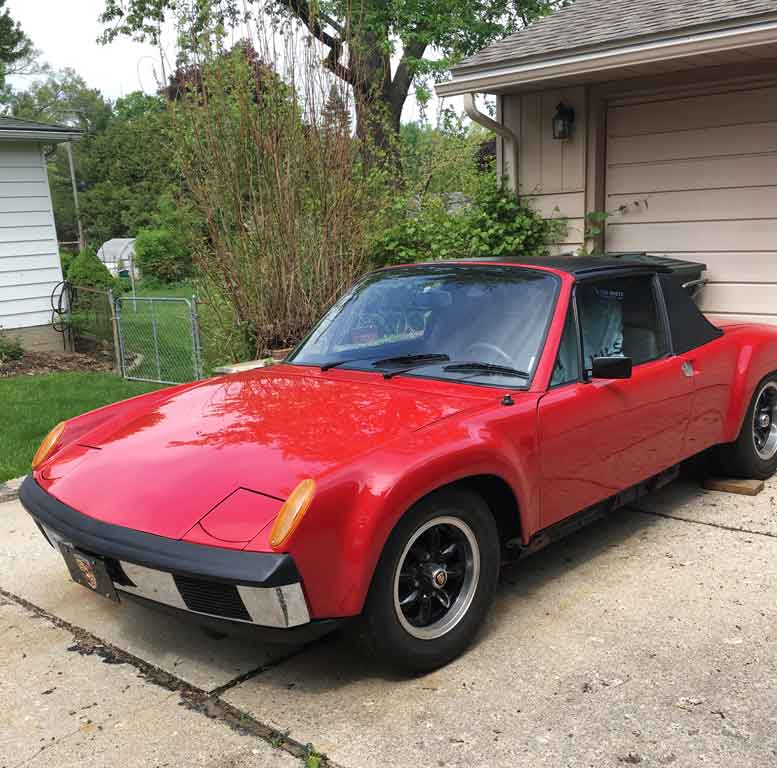
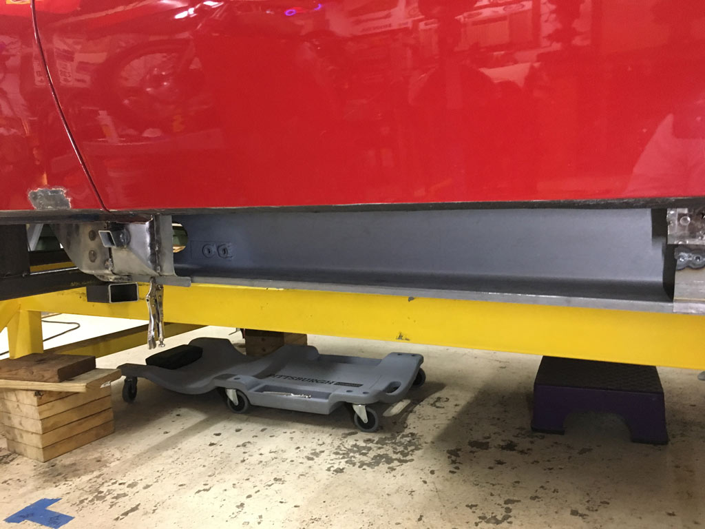
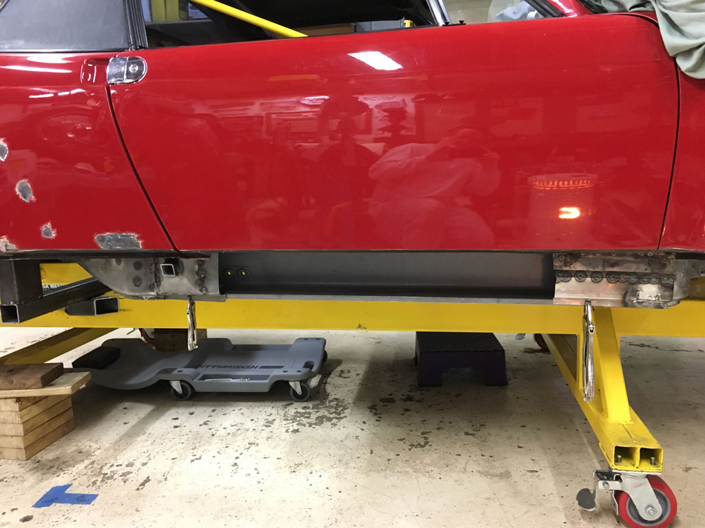
Looks pretty nice eh?
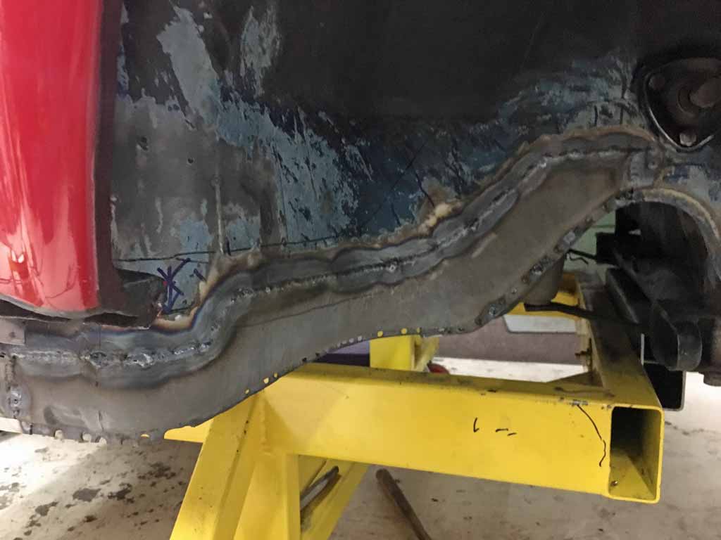
Here is what is lurking underneath once the rockers came off. 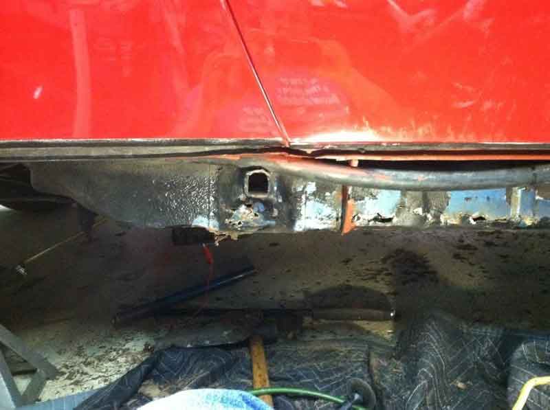
and when I started cutting back the rust. Oh my . . . .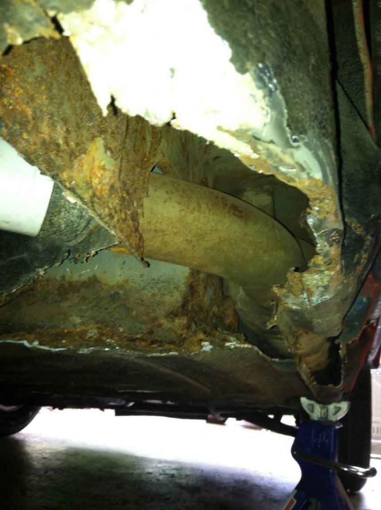
Posted by: Superhawk996 Dec 21 2018, 05:26 PM
With a new found 914 where else would I go but to the interwebz and I promptly found 914World! Much nicer than the old school 914 newsletters I used to have to subscribe to.

Everything you could ever want to know about 914's at your fingertips all on one place. At least this internet is good for something.
Basic Plan:
1) Find someone that has done it before
2) Follow their advice
I eventually found Jeff Hail's post on Bringing Out the Dead. Wonderful stuff and top level craftsmanship. It is so rare in these days to find someone so willing to share his skill and knowledge. I spent many hours reading that thread and many others on the site and I finally settled on a course of action. . . . copy Jeff!
http://www.914world.com/bbs2/index.php?showtopic=76791
Jeff's posts are so elegant and to the point. And to top it off he offered up a "blueprint" for his build cart.
So I copied it . . .  ruthlessly . . . . down to the paint color. Yellow makes perfect sense to me. Leave it raw, and it rusts. Paint it black and you'll surely smack your head on it having not seen it out of the corner of your eye.
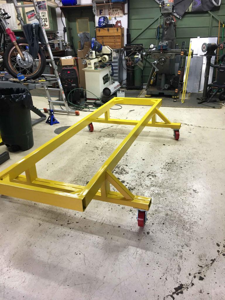
Posted by: Cairo94507 Dec 21 2018, 06:45 PM
 Well you found the best place in the world for a 914 owner- The World is here to answer all of your 914 questions and to assist in locating all of those hard to find parts. Welcome and enjoy.
  Merry Christmas.
Posted by: Superhawk996 Dec 21 2018, 06:52 PM
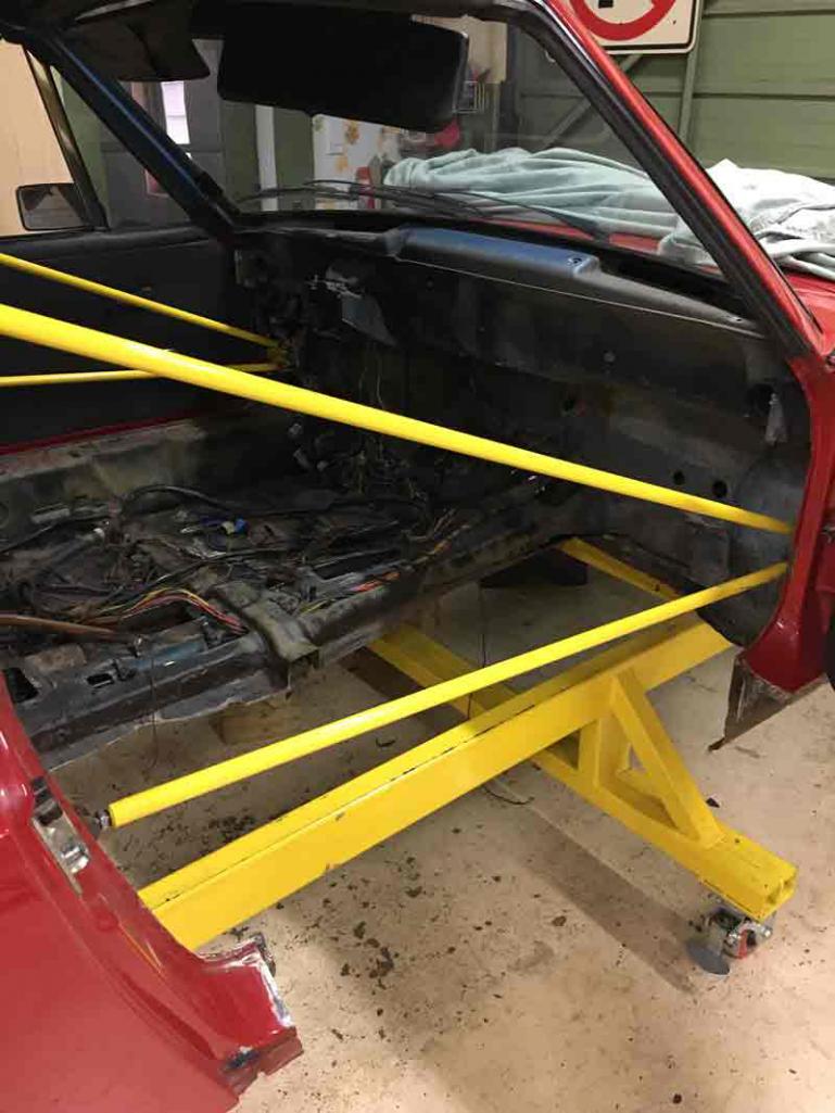
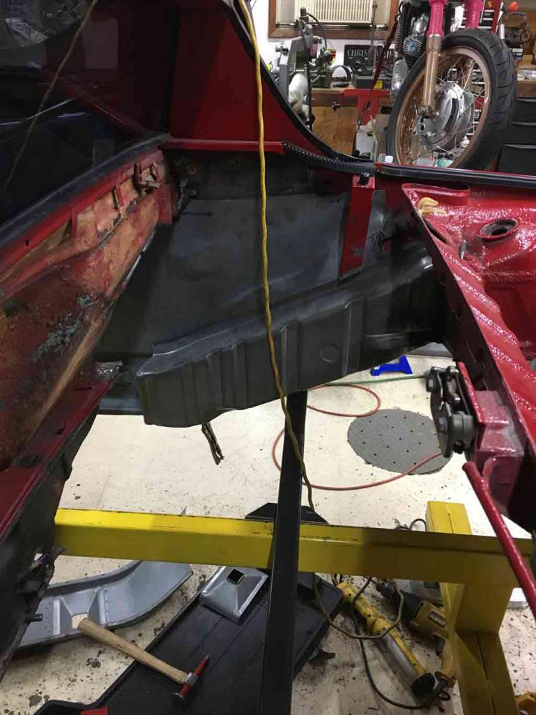
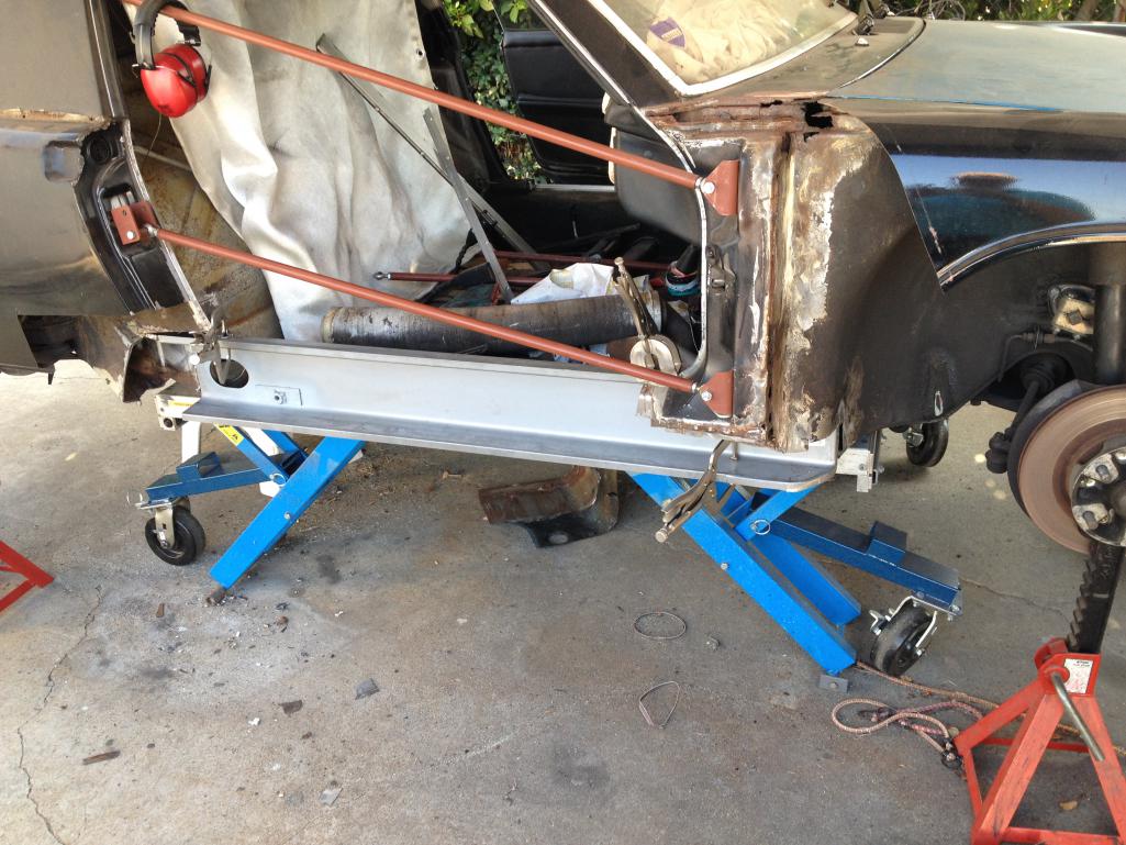
In the process, I also fabricated up some door braces mounting them on the inside of the cowl area to allow the doors to be kept in place to gauge door fits. The upper ties into the B=pillar seat belt attachment. The lower goes to the rear bulkhead. 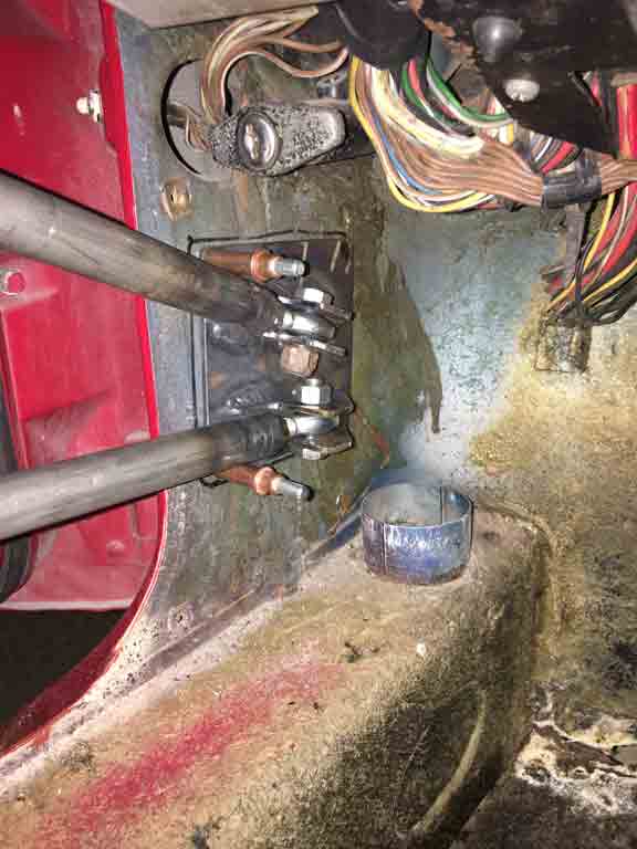
Additional rust excavation revealed that the fiberglass on the floor was a poor attempt to seal up the heavily rusted floorpan.
In the picture below you can see clear though the floor pan on the passenger side where it attaches to the longitudinal. 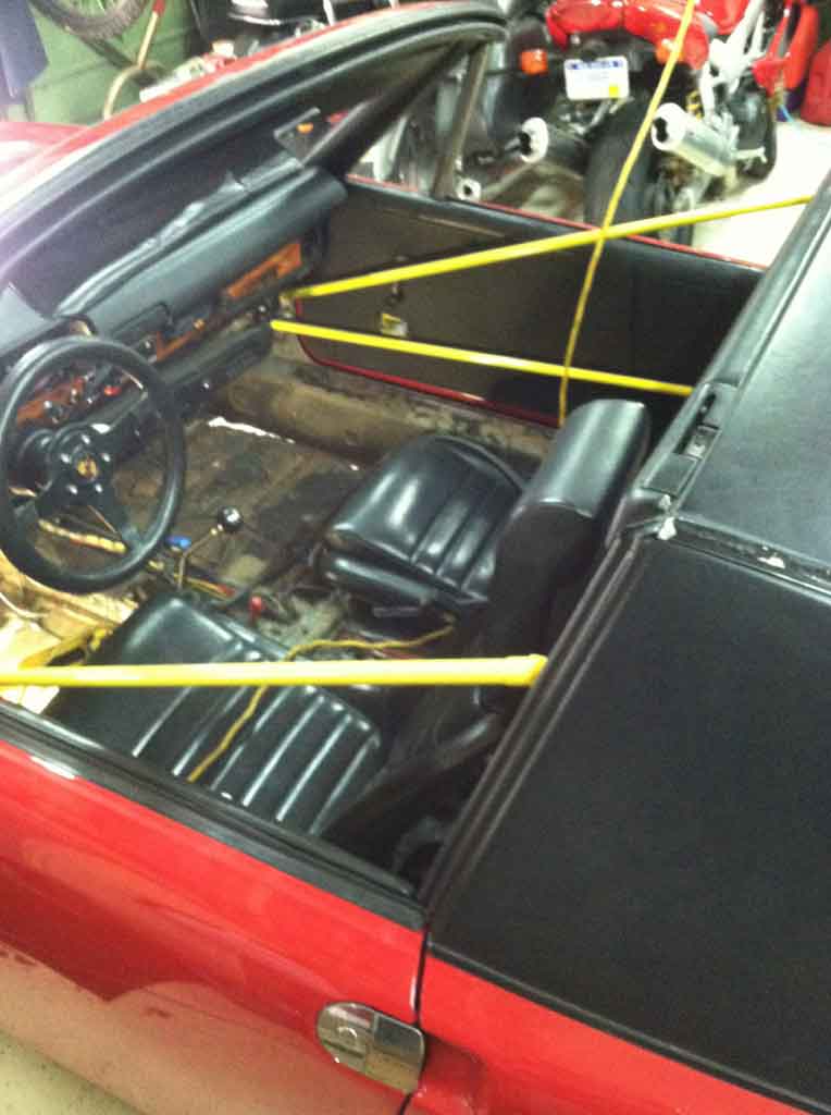
Posted by: Superhawk996 Dec 21 2018, 07:01 PM
At this point, it became clear that there would be more ordering of sheet metal than I had hoped for when I purchased the car. You know how this goes.
Hoping that maybe just a Engman or Restoration Design clamshell kit might be just enough to get er' back on the road for the summer and then come back at some point in the future to do it right. No such luck!

Posted by: Superhawk996 Dec 21 2018, 07:11 PM
This project started with a few goals in mind:
1) Save a 914 that otherwise might be a candidate for scrap despite how it looks from 20' away.
2) End up with a car of known pedigree. Going out and buying a $20K "rust free" 914 is no guarantee of getting a rust free car. As far as I'm concerned there really isn't such an animal. There are many nice cars out there. However, they all rust from the inside out. Don't get me wrong, I don't want to bag on anyone's car but I've been around 914's long enough to know they all have skeleton's in closet. For me, buying a known basket case is less traumatic than buying a $25K car and then finding out after the fact that someone creatively played a game of hide the rust.
3) Once I have a sound under body, then the possibilities are endless. Ultimately, I'd love to put a six in this car if I can ensure it is square and reasonably sound after fixing it.
Posted by: Superhawk996 Dec 21 2018, 08:07 PM
Alright, so now is probably a good time to plug a couple of vendors. I've been away from 914's for the better part of 20 years. It is so nice to come back and find that the internet has led to a vibrant 914 supply base.
Automobile Atlanta - they have been there since the start and though all my ups and downs as an owner. Good to see that they are still around.
Restoration Design. I am honestly impressed with these guys. Not only are they putting out some quality Porsche restoration sheet metal products, but I have a real appreciation for the fact that these guys are real tool and die shop type guys. Love the fact that they are making new parts that weren't even available on my last go round. I'm impressed with everything I've ordered from them so far and the customer service is top notch!!
Tangerine Racing. Awesome engine lift attachment for floor jacks. Why didn't I think of this after years of dropping engines as they wobbled around on a 3" diameter jack pad? I'm ashamed of myself! And to top that off, they make the bobbin's to replace the rear trailing arm fasteners. Not only have I broken one off myself in my original car (lots of work getting that out), my "new" car came with one pre-broken! Sure I could make one on the lathe but for the price, I'll gladly pay Tangerine $30 bucks or so and get onto the bodywork that this car so desperately needs.
Good job guys! Keep up the great work and thanks for keeping the faith!
Posted by: Jamie Dec 21 2018, 08:24 PM
You obviously know how to weld and have the tools, so dig in and good luck! We'll be watching for progress reports. 
Posted by: Superhawk996 Dec 21 2018, 08:25 PM
So what are the skeletons on this car that I've found so far (other than rust!)?
3 coats of paint. Original is Alaska Blue Metallic. Two repaints in red. Currently done in BMW #138 Cinnabar
Car was the victim of an A/C install (DPD parts). I'm very torn on this. My original car didn't have A/C. I had many sweaty summer drives on hot black vinyl seats! Now that I'm older and have enjoyed the A/C on the Miata I think it might be nice. On the other hand, the install is pure butchery! 
I'm trying to figure out a better way to do this. Maybe route the A/C lines though the tunnel when I have the floor pan off? Maybe do clean bulkhead pass-thru's into the cabin instead of just cutting holes with a hole saw?
Same for the York compressor and need to cut the right side engine shelf! No way.
There must be a slick way to mount a smaller Sanden compressor and/or do a top side center mount such that the butchery can be avoided.
There must be a better way. I've been poking around for ideas but haven'f found the right solution yet.
Posted by: Superhawk996 Dec 21 2018, 08:33 PM
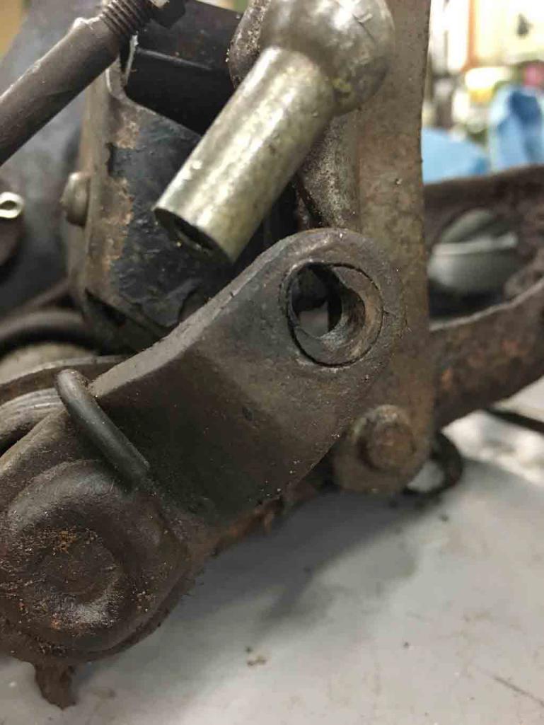
How about this one? Mileage on the ODO is 60K (ish). Must be 160K.
Here is the clutch pedal pivot. That kind of wear simply doesn't happen in 60,000 miles.
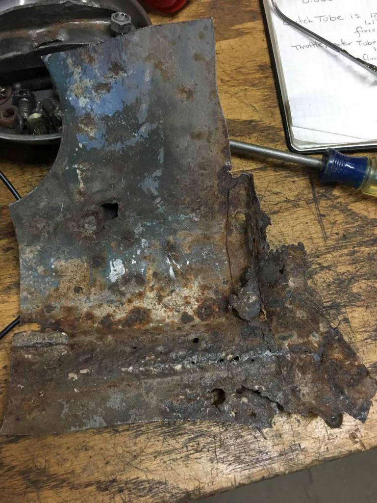
Posted by: Superhawk996 Dec 21 2018, 08:43 PM
All new vintage vehicle acquisitions come with surprises.
a 45 year old vehicle has typically had unmentionable things done to it. I've seen a lot of shady repairs but this vehicle is providing some new stories.
For anyone that might be reading this . . . Please take this as a warning and as a plea, brazing is not to be done on structural elements like the suspension console. if the metal is too thin to weld to, replace it! 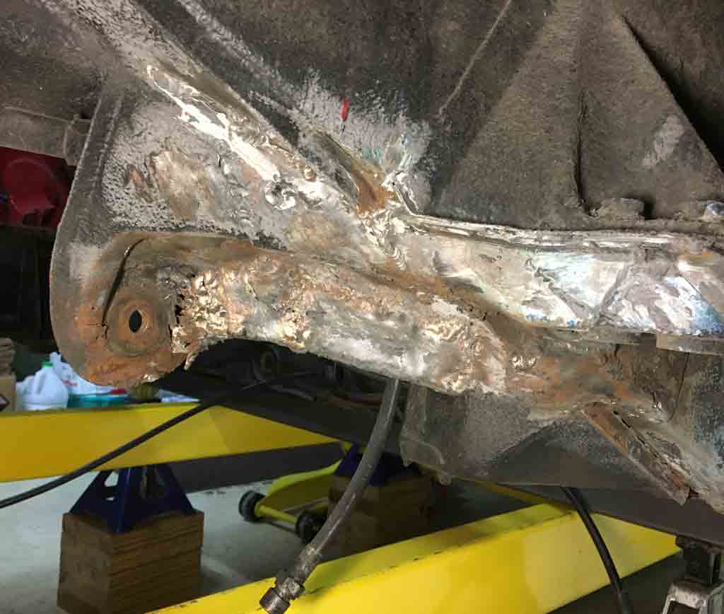
Posted by: Dave_Darling Dec 21 2018, 08:54 PM

I'm trying to figure out a better way to do this. Maybe route the A/C lines though the tunnel when I have the floor pan off?
There's a thread on here with a super-duper clean install of the AC in the stock cold air box. I know someone will be able to provide the link, hopefully soon. It is really an amazing build.
I have heard that you can use a setup like the smog pump pulley to run a modern compressor. Assuming it can hold enough power, that can give you room for the compressor without having to chop the heck out of the engine bay. You will still need to run the lines, though.
--DD
Posted by: Superhawk996 Dec 21 2018, 08:55 PM
This was another favorite. Some sort of home made Wheel spacers were glued to the brake rotors. 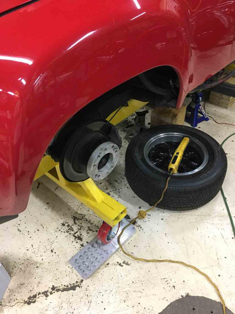
And to top that off, there was probably no more than 10mm of engaged thread on the lugs due to the added width of the spacers.
914's are already challenged with wheel balance since they are lug centric rather than hub centric. Adding in the imbalance of these wheel spaces must have resulted in "interesting" vibrations beyond 50-70 mph.
Luckily for me, my only "drive" so far has been limited to a 25 mph drive though the neighborhood once I got the engine running and the driveline back in operational order.
Unfortunately, that neighborhood drive also revealed a couple of brakes dragging pretty hard.
Posted by: Superhawk996 Dec 21 2018, 09:08 PM
Also found the driver side suspension console to have some stress cracking that lead to the start of rust. Not entirely surprising now that I suspect the chassis has about 160K miles. 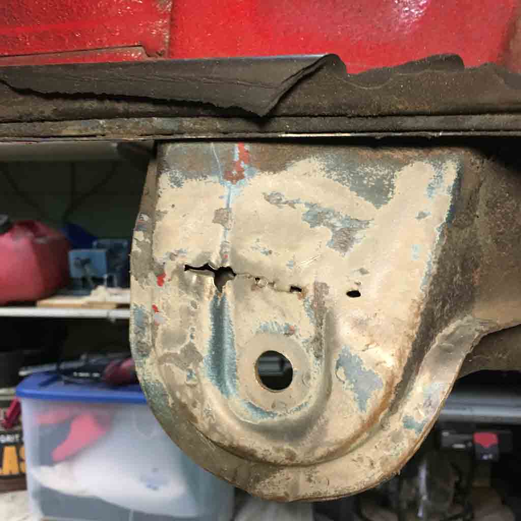
Unfortunately, there is no aftermarket sheet metal to replace the left side. I had a nice e-mail exchange with Restoration Design. It sounds like they are considering tooling up the left side suspension console but that it will take some serious time.
I've got to believe that at this point in time, many other "rust free" high mileage 914's are beginning to show their age and have similar stress cracking on the left side. I'm hoping Restoration Design will eventually produce this part.
Until then, I'll repair and reinforce it. If you're in need of a left side console, I'd recommend that you reach out to Restoration Design to reinforce the market need for left side suspension console parts!.
Posted by: Superhawk996 Dec 21 2018, 09:31 PM
All right, one last fun post for the evening.
I previously mentioned the fiberglass on the floorpan right?
Well, upon getting the right side longitudinal cut out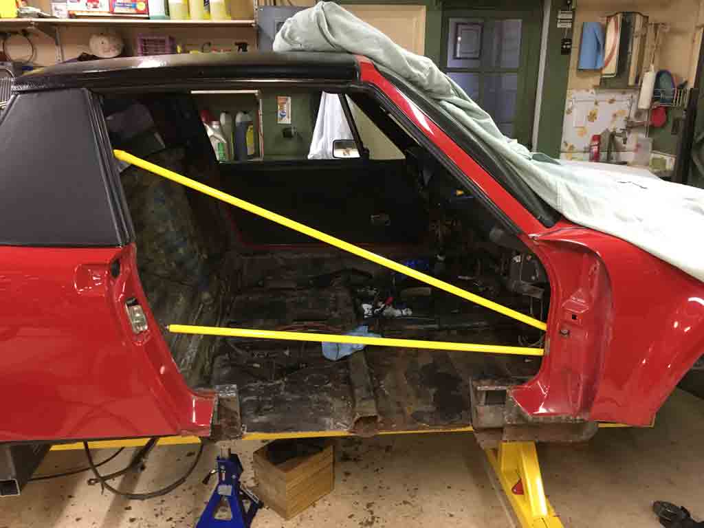
and sectioning the floor, it seems that someone thought they were building a boat. I understand the idea behind using fiberglass to seal up the pinholes in the floor pan. I don't think 1/4" of mat and resin was really necessary. 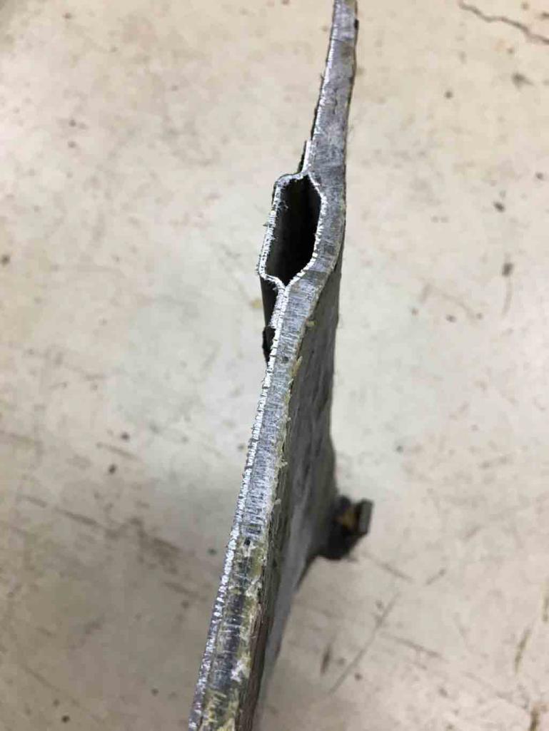

Posted by: euro911 Dec 22 2018, 06:04 AM
I really enjoy reading these kinds of brutal rustoration threads. Although I've been extremely fortunate that none of the 914s I've purchased were anywhere near this condition (being on the west coast), they did come with some minor age-related issues and/or PO hacks that needed to be dealt with. I'm OK with mechanical things like building motors, changing parts and repairing electrical systems, but I totally lack the welding, bodywork and painting skills some of you fellers have, and am in awe seeing the talent you guys display.
Subscribed to yet another success story in the making 
Posted by: 76-914 Dec 22 2018, 08:51 AM
That fiberglass added 40 lb's to the car. I always wonder why people want to dress up a basket case only to have the appearance of a nice care. Looks like she is in the road to a good recovery now. A while back we had a member who knowingly represented a "Polished Turd" as a jewel to an unsuspecting member. That went south in a hurry.  Looking forward to following your build and .
Posted by: bbrock Dec 22 2018, 09:40 AM
Anyone crazy enough to save a rusted out basket case is my kind of guy. Jeff Hail's build has been a great guide for many of us. Looking forward to seeing more of this one.
Posted by: Superhawk996 Dec 23 2018, 02:25 PM
Thank you for the kind words of encouragement! Will be trying to do some hardcore garage time between Christmas and New Years while I have some time off.
I'll put up some new posts in the coming days.
Posted by: Superhawk996 Dec 23 2018, 10:05 PM
Overall pretty happy with progress so far.
Floor pan and Inner Longitudinal removed. Lots of drilling of spot welds! Used the demo saw to remove more of the passenger side floor.

Then put passenger side door back on to gauge door fit. Overall I'm pretty happy. However, it seems the only way to get a decent fit is to shim the bottom hinge slightly (1 washer). I don't recall my old car having any door shims. However, it also seems odd that there is no way to "tilt" the door without using a shim.
Overall looks reasonable for a rough fit up but needs a little more tweaking. 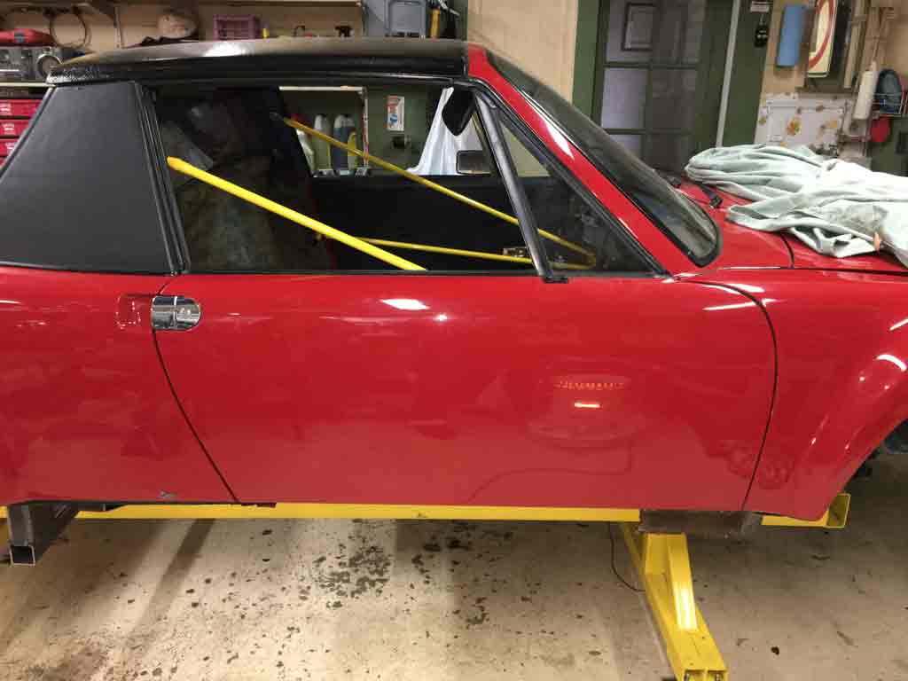
Posted by: Superhawk996 Dec 23 2018, 10:32 PM
Also did some more removal of the rear frame & inner wheelhouse. 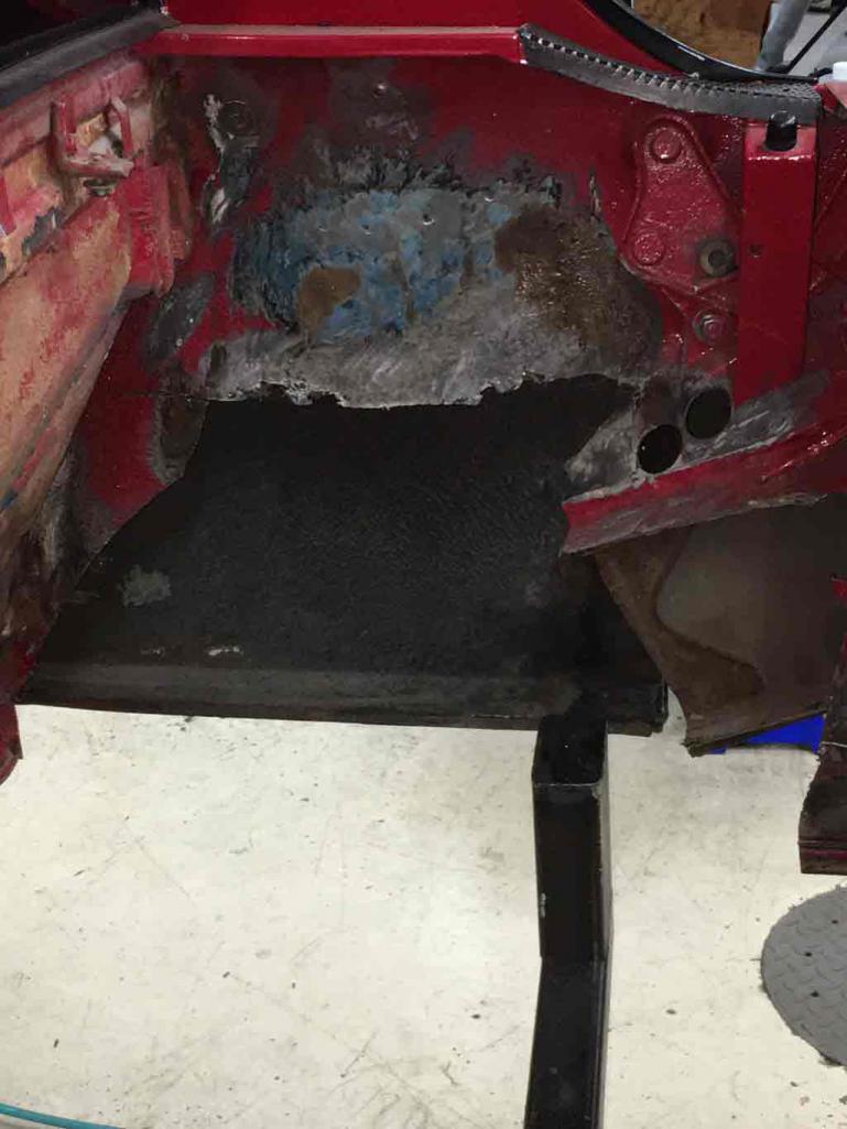
I can see that drilling spot welds is really going to be a re-occurring theme.
I can't believe how many spot welds are on the outer suspension console for the trailing arm. This is in addition to some factory MIG welds. 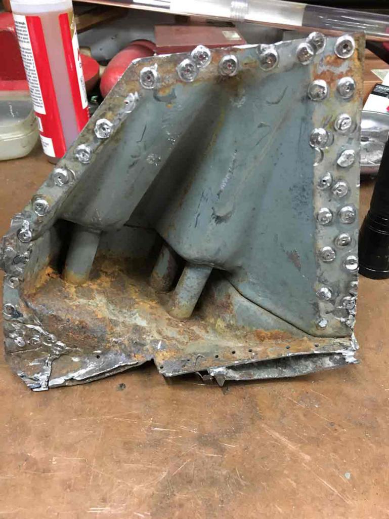
Pretty much the same story for the engine mount but with even more factory MIG along the outer perimeter.
Honestly, it took the better part of the day just to get these two pieces of sheetmetal freed up for recycling. Sure wish that new metal was available. 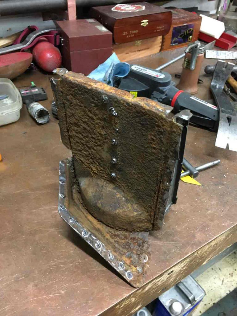
Just about the time I was thinking I was doing OK for the day, I got a little surprise. Turns out that during the demo of the frame, the saw blade had banged the rear fender from the inside -- totally buggering the paint.
This was a bit of a let down. Since the paint on the car is in very nice shape I've been trying to avoid cutting out a piece of the rear fender to allow easy access to the frame / console area like so may others have done.
I thought I had been careful. Nope. 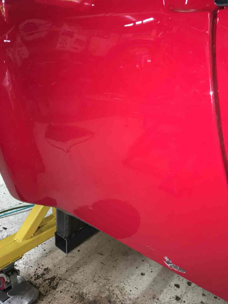
I think I'll still try not to cut out this section of rear quarter. At this point it is still easier to do a small paint repair than to deal with cutting into the quarter and having to deal with the fiberglass flares. Welding on the sheetmetal with the fiberglass is going to be a big problem that will likely force me to remove a portion of the flare, weld, and then have to reinstall the flare. Not a fun prospect.
Worst case . . . . paint will be hard to match. I had hoped to contain the re-spray to the door jambs and the engine compartment.
At some point, assuming I'm happy with all this structural work, I had planned to strip all paint in the future (maybe next winter) and return the car to original blue.
I had long ago resolved to never again have a red sports car. Can't tell you how many thousands of dollars I've paid to the highway robbers over the last 40 years or so. I've never changed the speed I drive but I can say with a straight face that white Miata never attracted 1/2 the attention my red 914 did!
Posted by: Superhawk996 Dec 23 2018, 10:42 PM
So after all that, I decided to take a look at how the rescued pieces will fit to the new sheet metal.
Gives me a good idea of what still needs to be trimmed & tweaked. 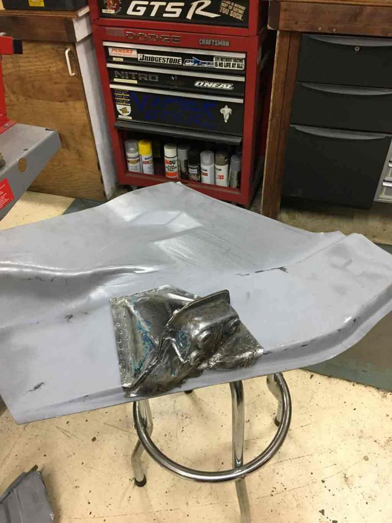
It also gives he a bit of hope and chance to forget the paint fiasco.
Two steps forward, one step back but focus on the overall forward progress.
I also had a chance to check out some of the projects you guys have posted.
Bbrock's project is awesome! Gives me hope that this is indeed worth doing. Likewise, I've been able to find a bit more info on a center mount AC compressor that another member did. Same thing, makes me realize that it can be done.
Such a shame the 914 had a relatively short life cycle. Had the line continued, think of the improvements that could have been made.
I was very excited a few years back when Porsche hinted of a return of the 914 (OK it was more like a decade ago!). But like a lot of concept talk around the auto shows, it was just a bluff!.
Oh well, if Porsche won't do it, I guess I'll have to keep the old school metal on the road on my own!
Posted by: sixnotfour Dec 23 2018, 10:46 PM
way to dive in...

Posted by: bbrock Dec 23 2018, 11:03 PM
Then put passenger side door back on to gauge door fit. Overall I'm pretty happy. However, it seems the only way to get a decent fit is to shim the bottom hinge slightly (1 washer). I don't recall my old car having any door shims. However, it also seems odd that there is no way to "tilt" the door without using a shim.
Overall looks reasonable for a rough fit up but needs a little more tweaking.
Believe it or not, you can often fix a sagging door by just grabbing the rear bottom and reefing up on it. Alternatively, if you look carefully, you may find a slight bulge in hinge pillar at the upper hinge. Over the years, the metal seems to stretch there and cause the door to droop at the rear. So you can gently push that bulge back with a body hammer. I was surprised how a tiny adjustment fixed my drooping doors. I used a combo of the two methods to fix the droop and achieve the gaps I wanted fore and aft.
Nice work you are doing!
Posted by: Superhawk996 Dec 23 2018, 11:22 PM
Then put passenger side door back on to gauge door fit. Overall I'm pretty happy. However, it seems the only way to get a decent fit is to shim the bottom hinge slightly (1 washer). I don't recall my old car having any door shims. However, it also seems odd that there is no way to "tilt" the door without using a shim.
Overall looks reasonable for a rough fit up but needs a little more tweaking.
Believe it or not, you can often fix a sagging door by just grabbing the rear bottom and reefing up on it. Alternatively, if you look carefully, you may find a slight bulge in hinge pillar at the upper hinge. Over the years, the metal seems to stretch there and cause the door to droop at the rear. So you can gently push that bulge back with a body hammer. I was surprised how a tiny adjustment fixed my drooping doors. I used a combo of the two methods to fix the droop and achieve the gaps I wanted fore and aft.
Nice work you are doing!
Tried that to a limited extent. However I pulled by back out really bad about a month ago so I wasn't in a hurry to overdo it! The "reefing method" is what used to get done in auto assembly plants to tweak door fits and window channel fits as recently as the late 90's. I might use a floor jack though if push comes to shove.
That was the 1st time for me with pulling my back like that and it was not fun and had me laid out for a couple days. I was trying to move my engine a bit without a dolly or hoist. Made the mistake of lifting and twisting at the same time. Used to be able to do that when I was 20. No so much anymore! Not only are the 914's older and in worse shape than I recall in the 80's -- so am I!
Posted by: bbrock Dec 23 2018, 11:37 PM
That was the 1st time for me with pulling my back like that and it was not fun and had me laid out for a couple days. I was trying to move my engine a bit without a dolly or hoist. Made the mistake of lifting and twisting at the same time. Used to be able to do that when I was 20. No so much anymore! Not only are the 914's older and in worse shape than I recall in the 80's -- so am I!
Oh man, I feel your pain. I was actually in my 20s, and it was the 80s) the first, and worst time I put my back out. Did if lifting a stainless steel pan that probably weighed all of two pounds and something I did hundreds of times each week for that job. But for some reason, my back went out and my knees just buckled. I had to chest crawl back to my office to call my wife. Then I had to somehow drive my 914 across town to where my wife worked so she could take me home. The only way I could operate the clutch was to put my foot on the peddle and then push my knee down with my hand. At least you were doing something manly and can blame age. I hope it heals quick.

Posted by: Superhawk996 Dec 23 2018, 11:53 PM
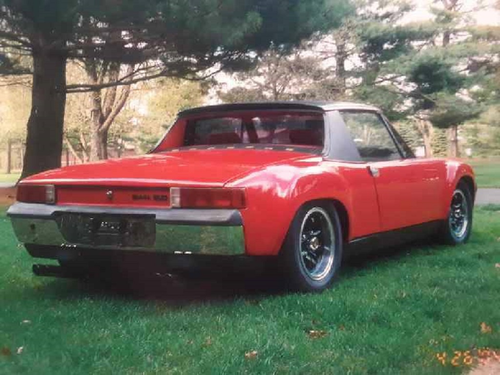
So here is a fun picture of my original 914 back in the early 90's.
They say that a 2 seat sports car is of limited use. I beg to differ. My buddy and I ran a house painting business during my 1st summer of college. I learned two important things.
1) Don't show up to do estimates in a 914. I never got any of those jobs. Wasn't until I started using my buddy's Citation that we started booking jobs!
2) You make do with what you have. This was bout a 16' ladder. At one point I had a 40' ladder on it but never got a picture of that one!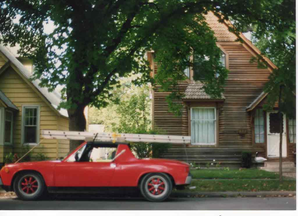
Posted by: whitetwinturbo Dec 27 2018, 12:00 AM
............I'm popped out just reading this thread ![popcorn[1].gif](style_emoticons/default/popcorn[1].gif)
Everyone is pulling for this one to be saved. Nice job!
Posted by: Superhawk996 Dec 29 2018, 09:02 PM
Getting back to work after a few days off.
Slow going lately. Still removing parts and cutting metal to get access to the Hell Hole areas.
Had to remove the trunk to get the old trunk hinges out. Of course that meant screwing around with the torsion bars which is always a smashed finger waiting to happen if not done properly.
Also a reminder that I need to move the battery to the frunk! Previously was crudely mounted in the trunk and taking up too much area in that already limited space. Plus I prefer the weight to go up front like I had it in my 1st 914. 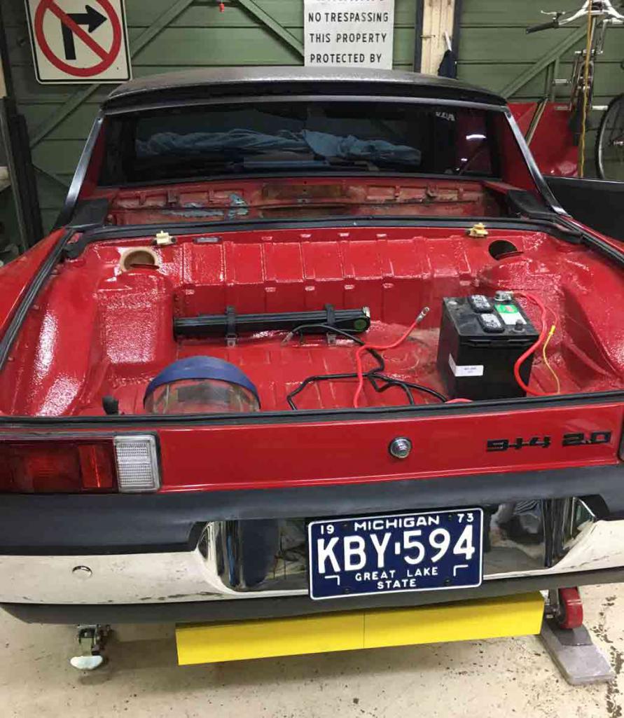
Previous paint job used bed liner type spay on material to hide a variety of repairs. I already know the rear trunk bottom edge has had the fiberglass treatment. Afraid to dig into that one this winter. Non structural and honestly, it is pretty inconspicuous at the moment. I don't see a way to repair this right now without ending up with even more paint work on my hands. 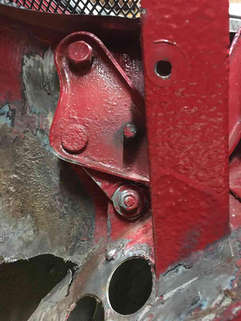
The trunk hinges had to be pulled:
1) to make way for new sheetmetal to repair the AC butchery. Hole saw pass thru is absurd. I can't believe the sheetmetal isn't rusted around the edges of the holes and leading to even more decay. Finally, a blessing! That is the mystery of this car so far. . . . how is the underbody so gone but the upper is in decent shape?
2) Repair the trunk hinge brackets. Although not broken off they were welded in with snot welds and look like they will eventually break. Even if they don't break I don't want someone to think I welded them!.
3) Upon removal, I discovered that the proper hinge bolts are long gone. Replaced with a 10 mm threaded bolt that is enlarging the bracket hole each time the trunk is opened. So the bright side is that I found this out before they broke! New brackets will address #2.
I'm constantly amazed how poorly previous owners took care of maintenance and repair. I understand 914's not getting due respect but come on. . . . 
Makes be a bit worried about getting to that engine and transmission.  I already know there are a couple of dicey exhaust studs and the compression is lacking
Got around to cutting the firewall to gain access to the Hell Hole to install the wheelhouse inner. More spot welds and cutting. 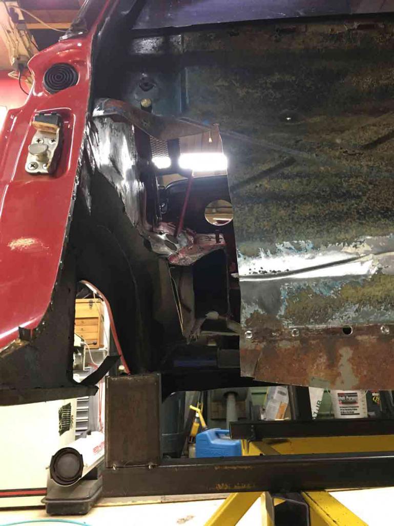
Spent the better part of two days getting this far. I think I was in for about 4 hours just to rough fit the inner frame rail. The way it fits up the the front of the trunk is tricky. Had to spend a lot of time reworking of the frame rail flanges to get it to fit right.
The one thing that bothers me is this frame section is corrugated. The original is two layers of steel. Inner is corrugated but the outer is smooth.
I think I'm probably going to have to fabricate a 0.030" (ish) outer layer to smooth out the appearance of this. Ideally, I'd like the rail to look OEM. May be too much work. Time to think that one over for a while. Open to suggestions if someone else has traveled this road. 
Lots of rough mock up to figure how how stuff will fit and what the best assembly sequence will be.
Discovered that the Restoration Design outer clam shell will need to cut into two pieces for my install. There is no way to weld on the upper portion without cutting off that rear fender so it will have to get welded to the wheelhouse section before that whole section is welded in. Also it needs to sandwich to the wheelhouse and the longitudinal which can't be done after the door jamb is finish welded.
Not a big deal but better to find it out now before welding starts!
Posted by: Superhawk996 Dec 29 2018, 09:31 PM
Posted a video up on YouTube. Posted as much for myself as a reminder that it did run . . .  and why I want to get it back on the road.
Shift linkage was out of adjustment and I had some trouble finding reverse and kept catching 2nd. That my story and I'm sticking to it. 
https://www.youtube.com/watch?v=jQ5_EblRToE
Posted by: Superhawk996 Dec 29 2018, 09:34 PM
Deleted duplicate post - oops!
Posted by: jmitro Dec 29 2018, 09:51 PM
https://www.harborfreight.com/4-ton-heavy-duty-portable-hydraulic-equipment-kit-62115.html
I used this tool to slightly stretch my very tight door gaps (and then I returned the tool for a refund after I got done
 )
)
Posted by: Superhawk996 Jan 1 2019, 12:08 PM
Spent a bit of time getting the 914 clock working.
Was initially non-functional when I first applied power to it.
Took a bit of poking around on the various forums to try to figure it out. Estimate to repair was about $285 from Hollywood Speedometer. I'm sure they would do a great job but that isn't in the cards right now.
Although I was able to get it working, it sill isn't fit for use and the front plastic lens is scratched. Oh, and the inner bezel is painted red (as are all my other gauges) -- Oh, the things people do to these cars! so at some point in time it may go in for a professional repair.
In the meantime, the curiosity of how it works and the itch to repair it was killing me.
When I first got it, the factory seal on the back of the clock was still in place which was a good sign. That meant only the front of the clock had been opened up to paint the inner bezel. Looking at the outer bezel closely did show signs of this but overall, it was done reasonably well and carefully without mauling the bezel too much.
Opening the back reveled the internal thermal fuse was open.
However, I put a jumper across it, and the clock still wouldn't run. It didn't start ticking on its own. I did eventually find that if I put some light finger pressure on the main spring gear that it would tick. I figure this was due to a gummed up mechanism.
Flushed the mechanism with denatured alcohol.
Repaired the thermal fuse. This one is a bit tricky. The back of the case says to only use 120C low melt temp solder. I can't seem to find this at a resonable price. I think the only solder alloy close to that temp is Indium based and the only places I could find it were about $250 for about 10 grams of it.
I did finally find some commercially available solder with a 138C melt point at Micro Center. Close enough for Government work. Certainly better than 60/40 Tin/Lead electronics solder with a melt temp of 188C but I'd rather eventually fix this in the long term. Luckily I have a power supply that I can do current limiting on so no risk in the short term. 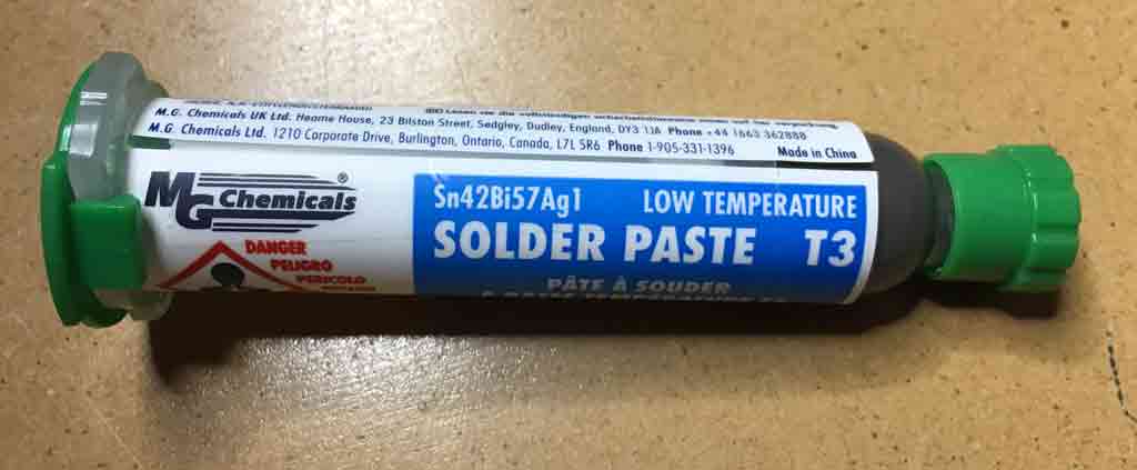
https://www.mgchemicals.com/downloads/tds/tds-4902p.pdf
Powered it up and voila! Or so it seemed.
Although it would run it wasn't self winding properly.
This is the most ingenious thing about the clock. When a set of contacts close, a solenoid is actuated which winds the clock. As the solenoid reaches the end of travel, the inertia of the winder mechanism carries it just a bit further than the contact on the solenoid arm, and opens contacts, and shutting off the solenoid. All this happens in a fraction of a second.
So what was happening is that although the contacts appeared to be closed, there were ever so slightly shy and not making electrical contact. I suspect this is due to mechanical wear, arching, or maybe something has gotten bent over the years. I tired cleaning the contacts but no luck.
I found that by putting a small shim (tip of a small tie wrap!) on top of the solenoid arm, it added just enough preload to close the contacts and to allow the winding mechanism to operate on its own.
Video below is with the tie wrap tip, taped into place with a small bit of green masking tape.
https://www.youtube.com/watch?v=NCQlqokfIPI
If anyone has more information on these clocks or has a more successful long term repair idea, I'd love to hear it. Otherwise I may eventually use a bit of glue to hold the tie wrap in place until I decide if $285 to restore the clock is worth it. Not likely in the short term until I get this car back on the road . . . I already have a $15 clock in my garage that works!
Also, I've found that a 1/2 Amp fast blow fuse is adequate to protect the clock in the short therm. The solenoid measures about 9 ohms so maximum steady state current flow would be 1.33 Amps by Ohms law. However, a solenoid is an inductor and inherently limits current in-rush and its inductance will be much higher than 9 ohms. I could dig up the equation to figure out the instantaneous inductance but that is too much work when trial and error works as well. Anyway, when I use a 1/2 Amp fuse, I can see the filament "bend" as the mechanism closes and current flows heating the fuse wire. However before it can get hot enough to blow, the current stops. In the long term, this bending of the fuse filament will fatigue it but for now, it works fine to protect the clock.
Posted by: bbrock Jan 1 2019, 01:41 PM
Happy New Year! Thanks for posting your clock repair experience. My clock hasn't been plugged in for 35 years and I can't remember if it was even working back then, so I may have to reference this soon.
FYI, I had my local glass shop cut new glass lenses for my tach which had a plastic lens and it was a reasonable price. Lenses on my console gauges look good but I may eventually do the same for them. SEM Trim Black is a dead nuts match for the satin black used on the bezels. I resprayed both inner and outer bezels on my main instrument panel gauges and they look like new. Much cheaper than a full professional restoration at least.
I'm curious about the thermal fuse. Is there no way to replace with one with long leads attached so it could be soldered in with normal solder without melting the fuse? Having never seen inside one of these clocks, just wondering
Posted by: Superhawk996 Jan 1 2019, 02:42 PM
I'm curious about the thermal fuse. Is there no way to replace with one with long leads attached so it could be soldered in with normal solder without melting the fuse? Having never seen inside one of these clocks, just wondering
Pelican forum has a picture that is not very clear - I'll try to post something a bit clearer in a day.
The bottom line is that the answer to the question is No. if the internal fuse is melted it needs to be re-soldered.
I've read of others just using normal solder and then putting the fuse external to the clock. Per my post, 1/2A fast blow would do the trick. However if the internal fuse melted (as mine was) it would need to be resoldered to get power to the solenoid. If you get closer to doing this, I'd be happy to walk you though it with better pictures or video.
https://cdn9.pelicanparts.com/techarticles/mult_vdo_clock_repair/fig3.jpg
Posted by: euro911 Jan 1 2019, 03:24 PM
Is there enough room inside the housing to solder in a miniature fuse 'socket'? Then you can install a small replaceable 1/2 amp fuse without worrying about melting the element when it needs to be replaced. I've replaced mini-fuses in old VCRs and microwave ovens, they're something like 1/8" diameter x 1/2" in length ... (unfortunately, I forgot the size designation)
Littlefuse also has miniature ceramic fuses with axial leads that could be used if you heat-sink each lead while quickly soldering one in 
https://www.littelfuse.com/products/fuses/axial-radial-thru-hole-fuses/pico-fuses/251/251_5.aspx
Posted by: Dion Jan 1 2019, 06:25 PM
Just spotted this thread. Nice work! & Good luck.
Look forward to seeing your progress. Looks like you have a handle on it all.
Posted by: bbrock Jan 1 2019, 06:42 PM
Littlefuse also has miniature ceramic fuses with axial leads that could be used if you heat-sink each lead while quickly soldering one in
https://www.littelfuse.com/products/fuses/axial-radial-thru-hole-fuses/pico-fuses/251/251_5.aspx
Yeah, those are what I was thinking about too. Here's an example of what I was looking at: https://www.galco.com/buy/NTE-Electronics/NTE8149?source=googleshopping&gclid=EAIaIQobChMIsoPKku7N3wIVoCCtBh0QYAJ7EAQYASABEgIvMvD_BwE
Posted by: Superhawk996 Jan 3 2019, 07:58 PM
I suppose you could add in one of those miniature fuses but it wouldn't serve much of a purpose.
What maybe isn't clear is that the internal "fuse" is the dab of low melting temp solder itself. Tthere are basically two "eyelet" loops.
One is fixed firm to the solenoid. The other is "sprung" down from the rear of the clock. This is just a piece of spring steel that is copper plated.
The sprung eyelet portion is pulled down to the fixed one and then the solder is placed which holds the two pieces together.
If a short were to occur in the solenoid, or if the mechanism were to jam preventing the winding contacts from being opened after only momentary contact, the thin spring steel will heat up, melting the low temp solder and the "fuse" then springs open breaking the current flow.
Remember, the purpose of the fuse isn't to protect the clock, rather, it protects the car's wiring.
So if the internal fuse is already opened from whatever cause, the root cause needs to be fixed. In my case this was to flush the sticky internals with alcohol to free up the stuck rewind mechanism and the mainspring gearing.
In theory, if you either put the mini-fuse inside (maybe between the eyelets) or outside the clock, it wouldn't really matter. Just protect your vehicle wiring.
I looked at the spec's on the mini-fuses you linked to. Those take quite a while (up to minutes) to blow depending on size of the fuse. It would take some careful sizing to get the right fuse vs. time to melt it. I'd prefer to just go with a simple external 1/2 fast blow automotive glass fuse since I know this works to run the clock but would also be low enough amperage to blow well before melting the clock power feed if a short were to occur.
Attached is a closer view. Sorry for limited resolution. I can send high res photo via e-mail if that would help.
Yellow arrow points to the "sprung" eyelet. Red circle is around the two eyelets that are now soldered with the low temp solder. 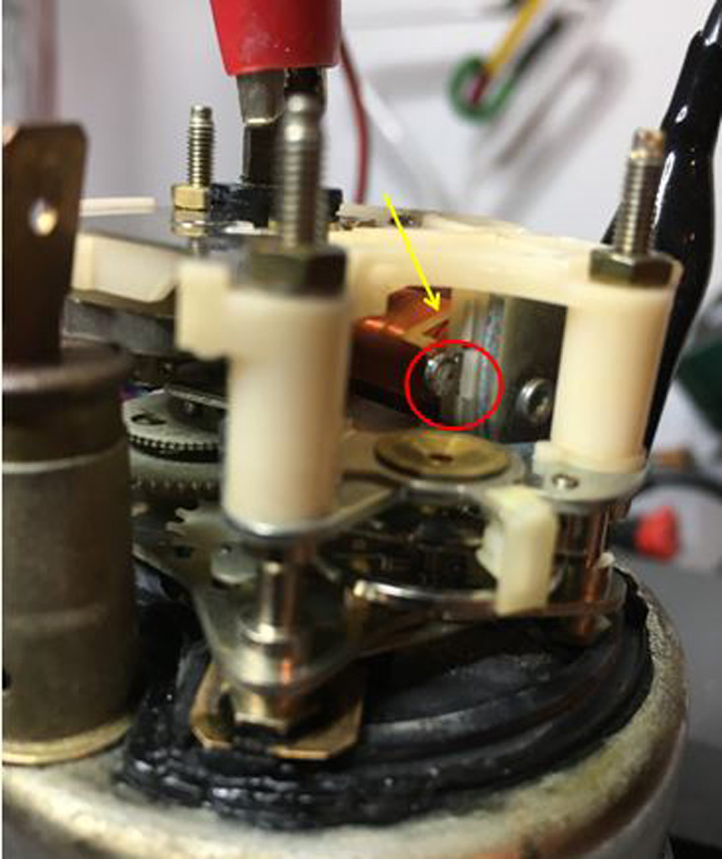
Posted by: FourBlades Jan 4 2019, 08:40 AM
Great looking restoration!
Check out this page for rear suspension inner console reinforcement plates:
http://www.tangerineracing.com/chassis.htm
John
Posted by: bbrock Jan 4 2019, 08:49 AM
Thanks for the details on the clock. Makes sense now. I'm thinking maybe I should open mine to clean and relube before plugging it in as a preventative measure.
Posted by: Superhawk996 Jan 5 2019, 05:59 PM
Happy to be of help!
I ordered some special watch oil that is supposed to be used to lube the clock jewel and other mechanical pivots. We'll see how that works!
I especially appreciate the tip on the trim spray and on getting glass cut - something will definitely have to be done to correct the red inner bezels!
I think I may try to polish out the plastic lens. If that doesn't work I'm going to try your glass tip.
Posted by: Superhawk996 Jan 5 2019, 06:07 PM
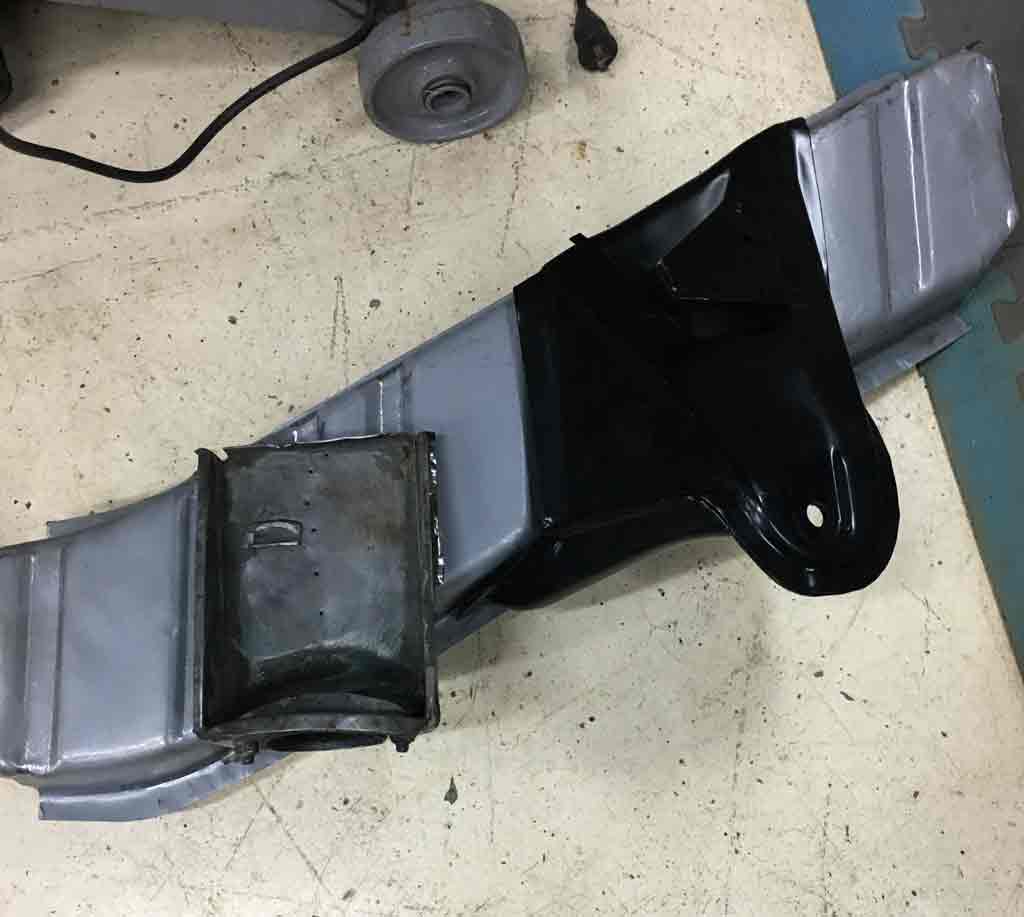
Didn't get much done that looks impressive.
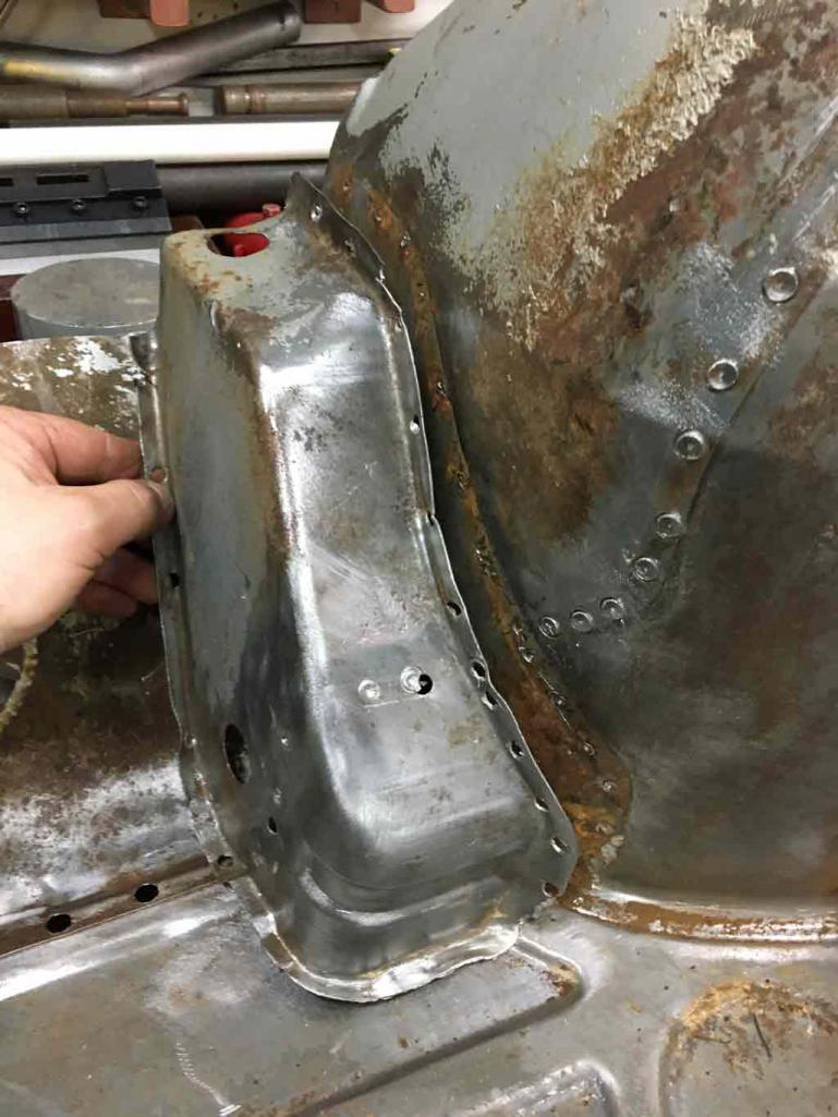
I did sandblast and prep the engine mount with POR Metal Prep.
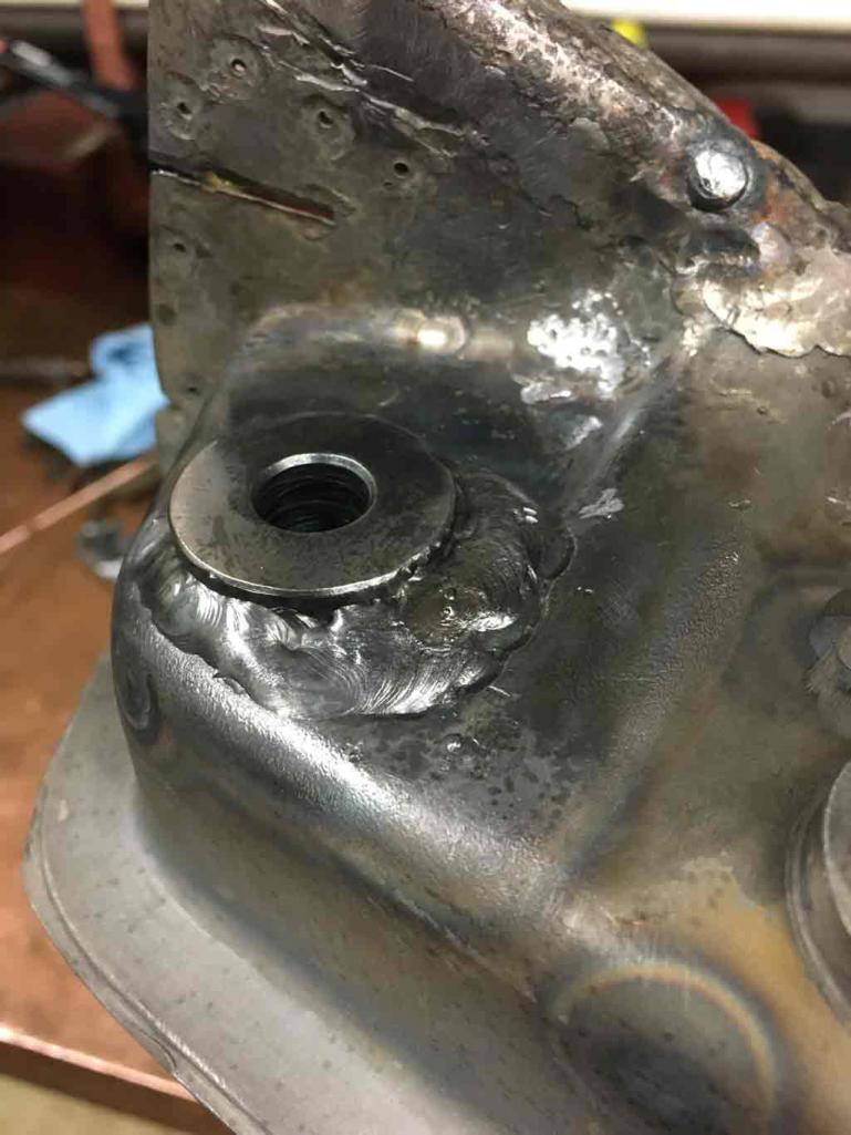
Back side was pretty heavily pitted. It cleaned up but there is some metal loss. 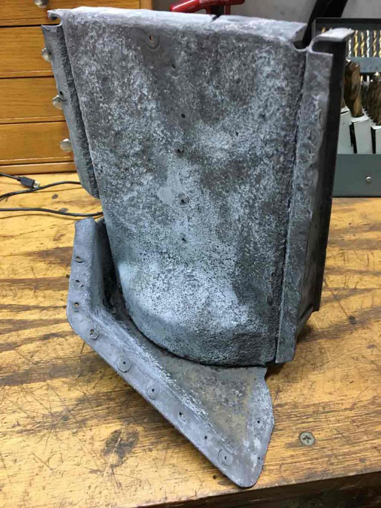
Does anyone have any tips on what to do with the heavily pitted material?
Front slide looks good. 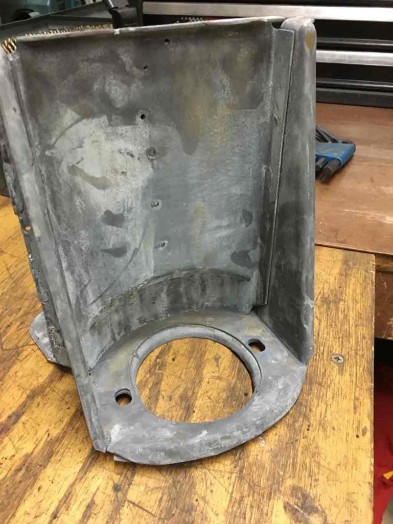
Seems like if I've gone to this trouble to do all this removal and salvage of the part, I'd rather know that there is enough material there for sure.
I think there is still enough base metal there to weld to but would feel better if I maybe doubled it from the front side?
Posted by: Superhawk996 Jan 19 2019, 11:35 AM
Great looking restoration!
Check out this page for rear suspension inner console reinforcement plates:
http://www.tangerineracing.com/chassis.htm
John
Thank you -- Love Tangerine!! Bought a set but haven't had time to get to these yet.
Posted by: Superhawk996 Jan 19 2019, 12:08 PM
Have not posted in a while but I've been working. Not terribly exciting visual progress.
At this point I'm basically struggling with too many degrees of freedom on placement of the inner wheel house panel.
I was finally able to settle on that and have since Cleco'd it into place after I was satisfied that the panel is in the right fore aft direction and also that the basis of the interface to the inner and outer longitudinal are at the right Z height and are basically level to the other driver side rail as a reference. 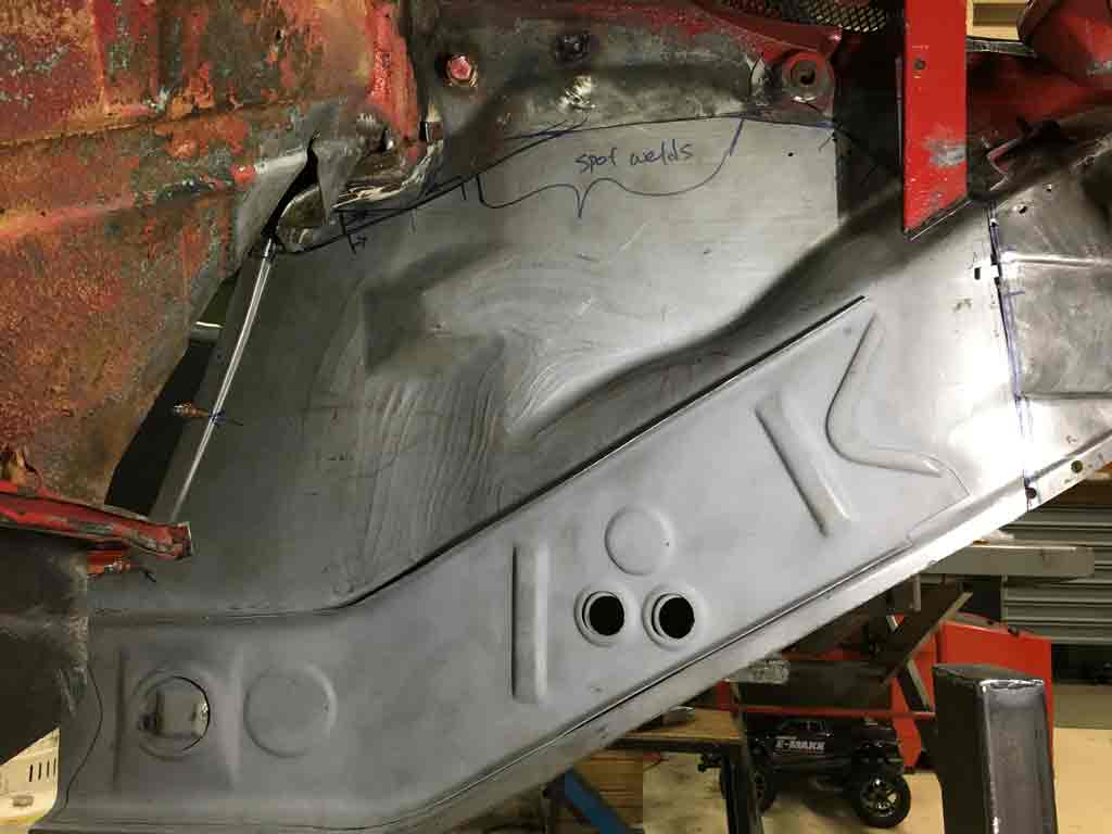
Spent the last couple weekends on two tick points:
1) Jack post location & prep
2) Getting outer suspension trailing arm mount prepped
On the jack post front I ran into a interesting issue. Since I've been using Jeff Hail's Thread as the basis for getting me started and rationality checking what I do I found that the dimensions he had noted didn't match to my vehicle for the jack post location.
Jeff has kindly posted so much information and he's a much better artist than I will ever be. I think this one may have been a typo. 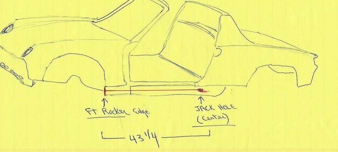
Dimension of 43 1/4" didn't match my vehicle though all of Jeff's other measurements for things like the suspension console mounts did match exactly.
This lead to much double checking and trying to figure out if I was doing something wrong. Ultimately the measurements from my car need to be considered "master" for my project.
In my case my jack post needs to be at 47 1/4 inches as measured from the very front of the front fender lip that the outer rocker locates from. It was the same for the driver side on my car. 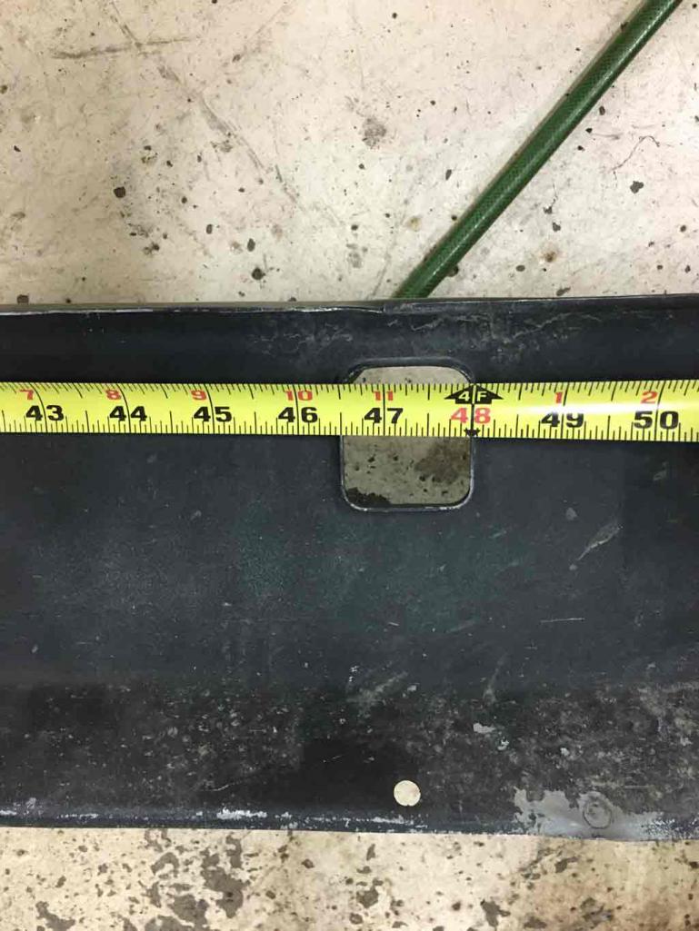
I can't reiterate the importance of doing mock up work just to double check. 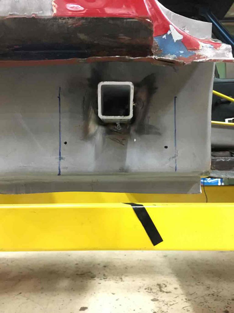
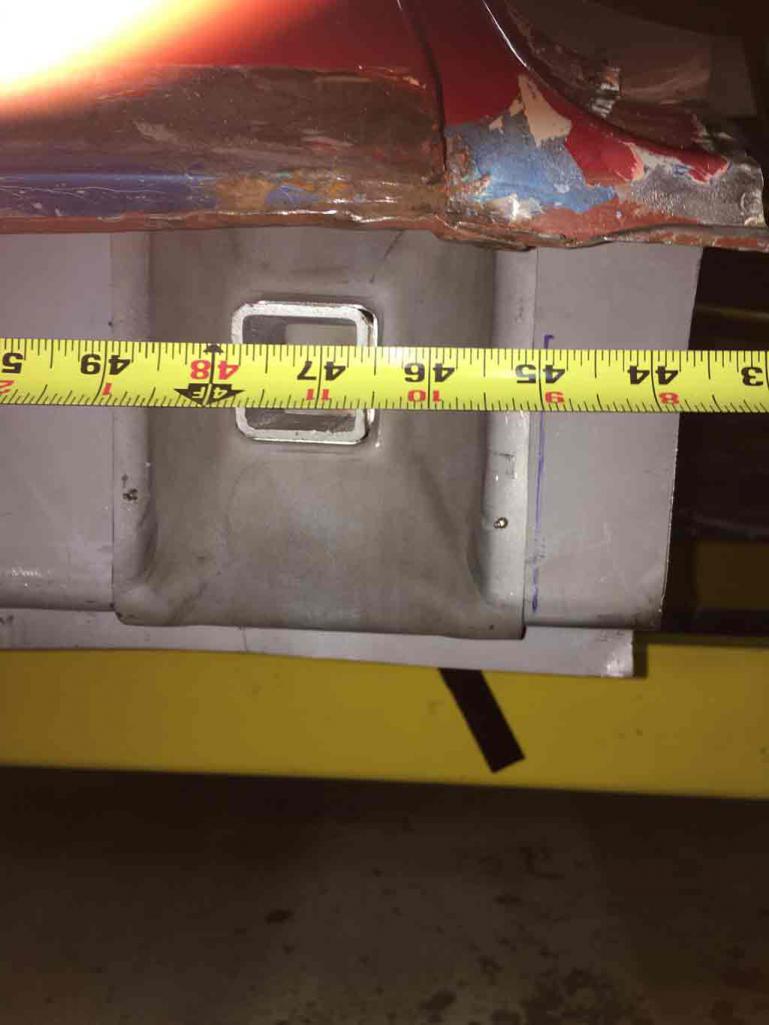
In my case, installation of the outer rocker confirms that 47 1/4" is the right measurement for me. 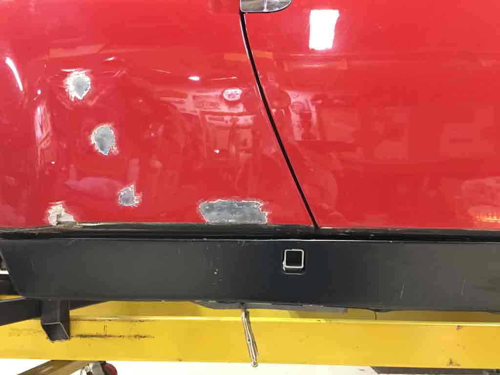
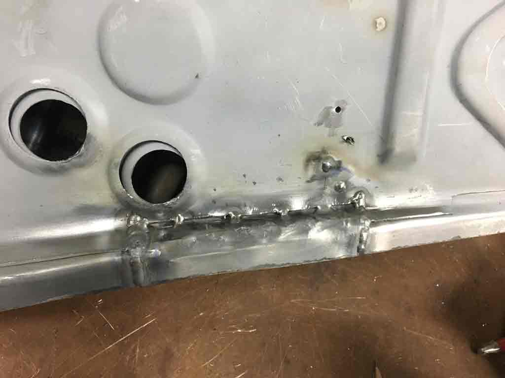
So satisfied that I had things in the right place, I've welded the jack post to the Wheelhouse panel. 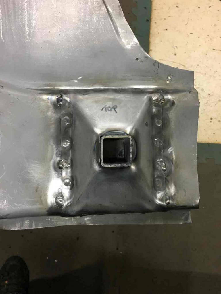
Posted by: Superhawk996 Jan 19 2019, 12:34 PM
The trailing arm mount on my car came with one of the three bolts pre-broken and better yet, there were remnants of a broken EZ-OUT in inside the bolt hole. The only real way to fix this is to either use and EDM machine to burn the hardened extractor out (not possible on vehicle) or to replace it.
This lead to me ordering a bobbin from Tangerine (Did I mention they are a great vendor ).
First I cleaned up the other two holes with a tap and Proof Torqued the fasteners to make sure they were sound and would hold torque. It would be really crappy to find out later after welding the console mount that one was weak and would strip. 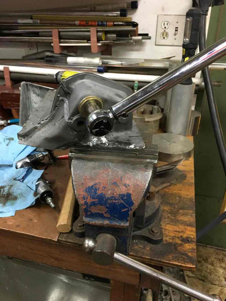
Putting it in the new bobbin took a bit of time. However the one thing I can say with absolute certainty is that this was much easier to do on the bench. I wouldn't look forward to doing this under the vehicle
Started by removing the bad bobbin.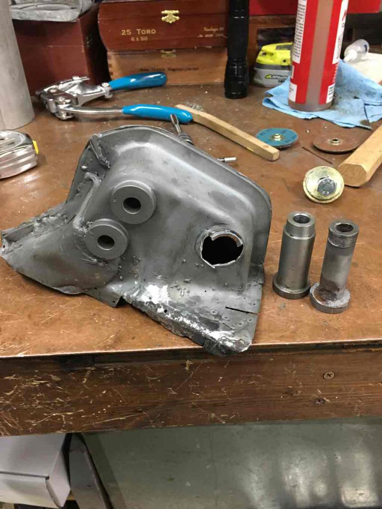
The new bobbin is on the left.
Since my outer console mount had some metal loss on the floor of the mount, I decided to put in some new metal as reinforcement. Had to do a little pattern development. 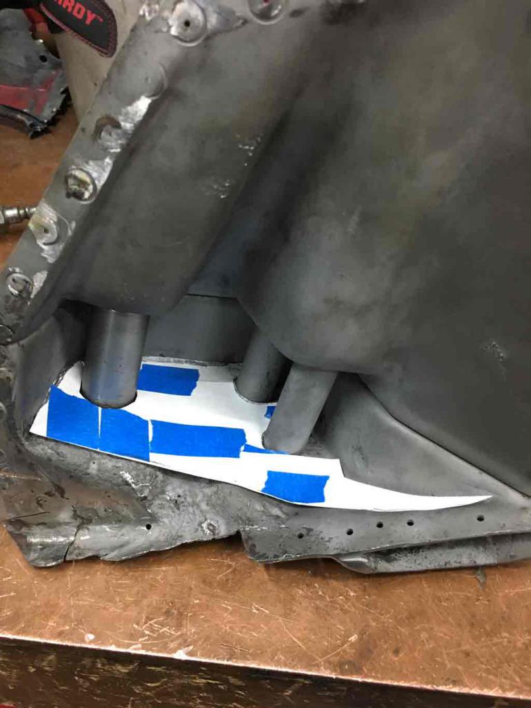
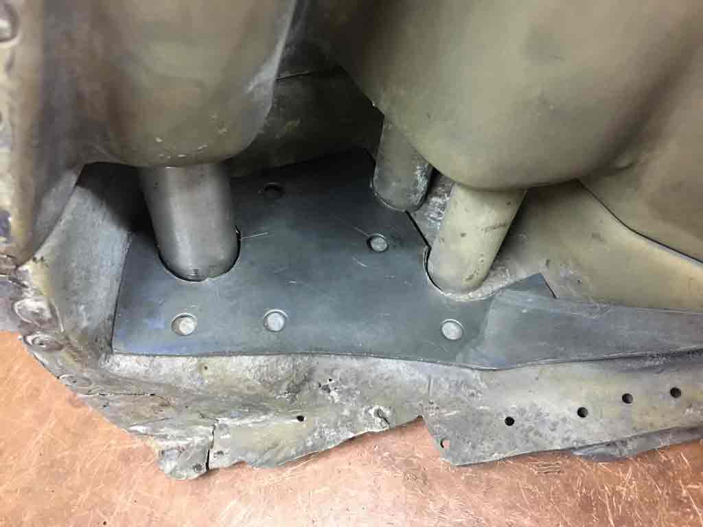
Welding in the reinforcement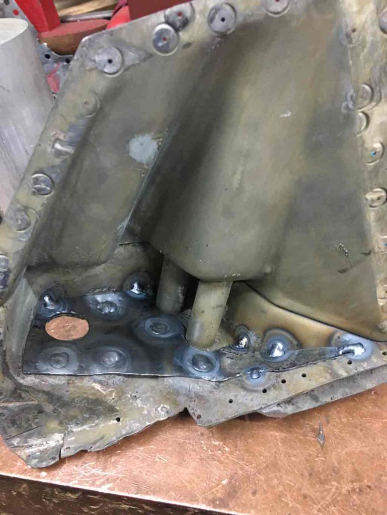
I also ran into a little problem where the new bobbin wasn't at quite the same height as the other two. It was maybe about 3/32" too low. I used the old trailing arm outer pivot to serve as a datum. By tightening the other two bolts first the third can then be pulled up to the right height. At that point I began tacking and final welding. 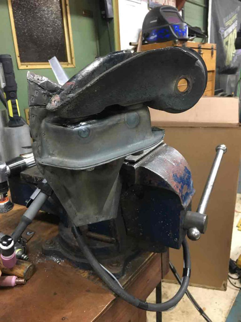
I also predictably ran into some issues blowing holes into the thin pitted metal that was previously reinforced. Patience . . . and TIG welder really helps with this. 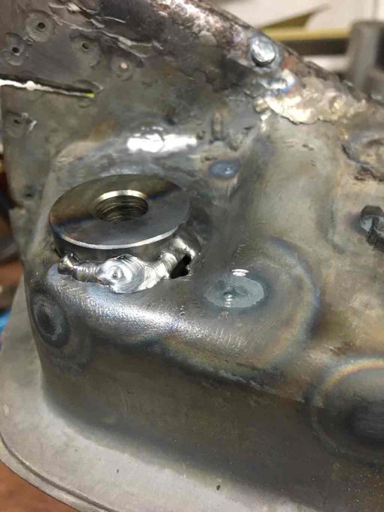
All in all things turnd out to may satisfaction. 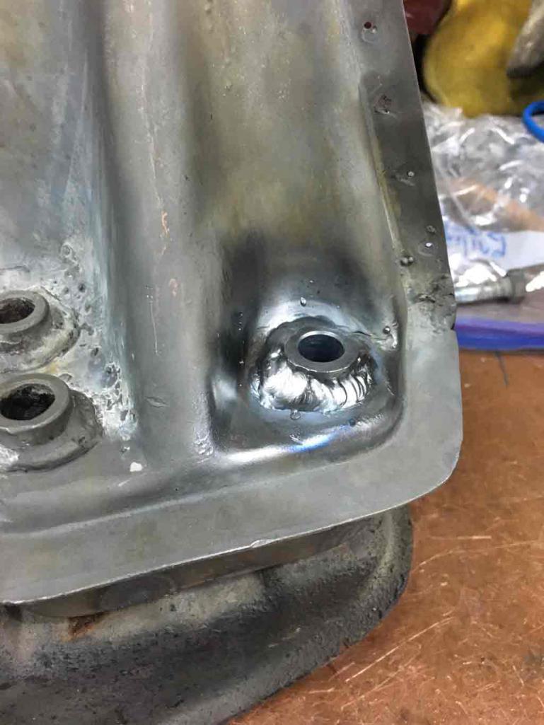
Next step: Gotta get this located properly to the inner wheelhouse panel. In my case, since I didn't cut the outer quarter panel for access, it needs to be welded to the panel before I weld in the wheelhouse panel.
Posted by: euro911 Jan 19 2019, 04:44 PM
I drill two holes in the bottom of each jack point support to allow for better drainage.
Then a small dose of Eastwood's Internal Frame Coating can be sprayed in there to keep the inside surfaces protected.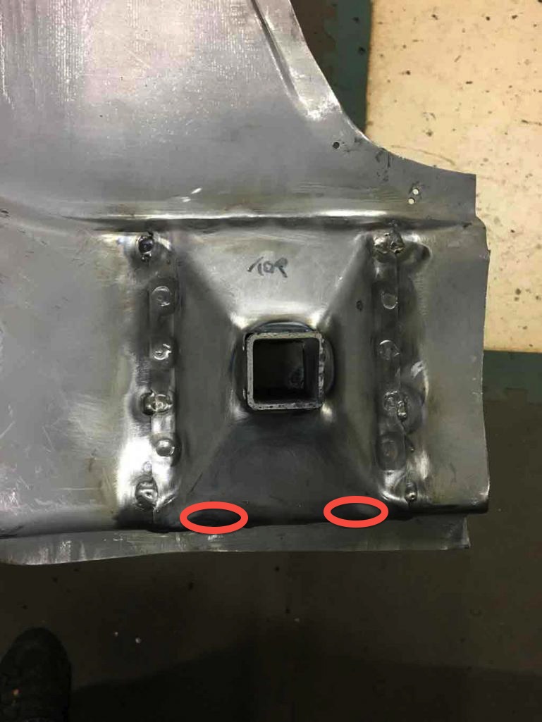
Posted by: Superhawk996 Jan 26 2019, 10:11 AM
I drill two holes in the bottom of each jack point support to allow for better drainage.
Then a small dose of Eastwood's Internal Frame Coating can be sprayed in there to keep the inside surfaces protected.
Thank you for confirmation others are doing this. I think this probably is the right thing to do. I was thinking of this when I was welding it up. the two options are keep water out which is near impossible or give it a way to drain. I will drill holes and coat the inside with paint before I do final assembly to the vehicle.
Posted by: Superhawk996 Jan 26 2019, 10:32 AM
Having a rough go of getting the trailing arm mount positioned properly. I've been chasing measurements around the past couple of weekends. May be drifting into OCD territory on this but I'd really like to ensure the suspension mounts are located as exactly as possible.
Would appreciate any insight from others that may have fought this battle. 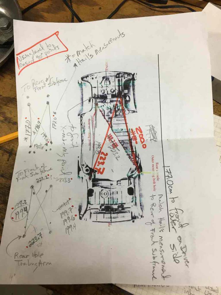
Currently can get X/Y dimension correct but Z dimension is too low by 5-6 mm. Trying to force it up in Z results imparts a twist to the body at the rear locators of 4 mm. I'd rather not do that.
Due to the geometry of the frame rail, the X dimension and the Z dimension are interrelated. the dark blue line is where the mount wants to be if Z dimension is correct, the current (orange line) is where X/Y dimensions are correct. You can see the variability between them and how they are related by the angle of the frame. 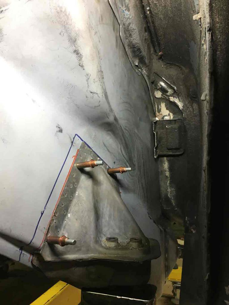
I've been using a trammel to measure the body locations but this measurement technique seems to have about 3mm of error on each end depending on how square the measurement point is to the trammel. This could account for up to 6mm of measurement error end to end. 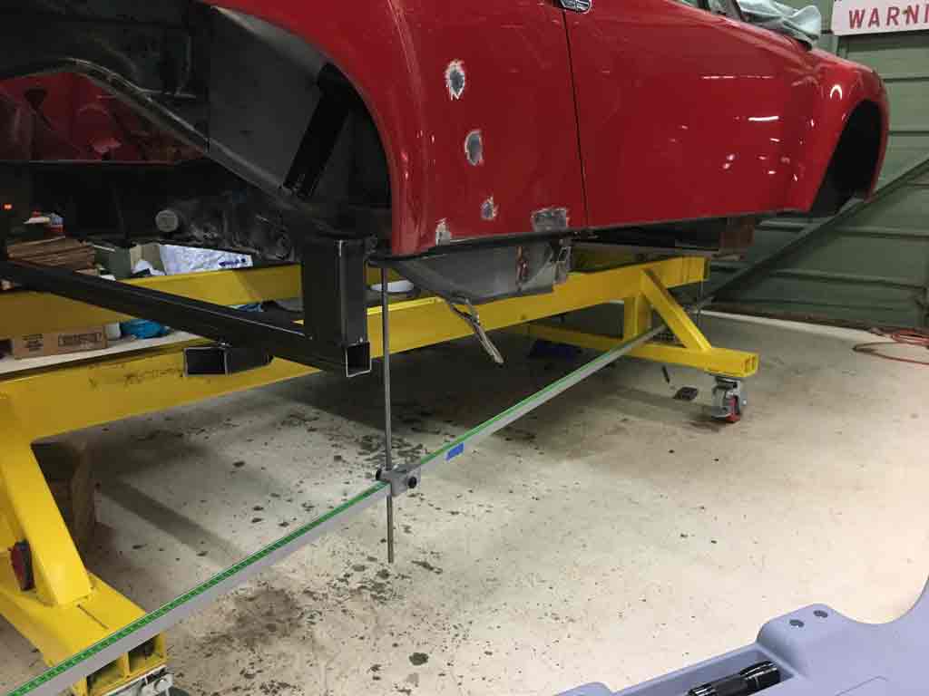
Ideally the trammel extensions should be kept as short as possible to minimize parallax error. However, that isn't possible given the need to clear the body cart and the difference in Z height between the front mounts and the rear trailing arm mount.
The error is actually much larger than 3mm unless I use a level to ensure that the trammel extensions are 90 degrees to the trammel bar.
I had loaned a laser plumb bob to a buddy for the last couple years to do a basement remodel. I've gotten that back and intend to remeasure everything today using the laser to drop the suspension locators to the floor and then measure that with a simple tape measure.
The laser plumb bob specs are +/- 3mm at a 15m on the laser projection upward and +/- 6mm at 15m on the downward projection. The downward projection is literally an inch off the floor so that error is negligible. Likewise, the up projection will only be less than 1 meter so again negligible. . . . . IN THEORY. 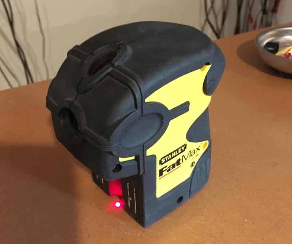
We'll see how this works out today. 
Posted by: Superhawk996 Jan 26 2019, 10:47 AM
Also picked up some front brake calibers from PMB to address my old ones that were sticking during my October "test" drive.
This is always a tough call given that I'm a pretty cheap bastard. Rebuild myself and save money but takes time OR pay someone else $$ and save time. Right now my time is in shorter supply.
I've rebuilt 914 calipers before and quite frankly it is a bit of a pain. And even when I've done it they still end up looking ratty even though they are perfectly functional.
I've got to say that the work PMB does is top notch. Automotive jewelry  !
! 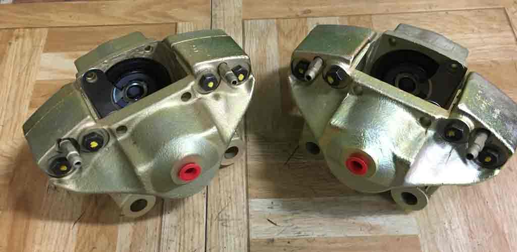
I intend to pick up some rears and to have my proportioning valve freshened by PMB as I can cash flow that in the coming months.
Posted by: Superhawk996 Jan 30 2019, 09:59 AM
Update on the trailing arm mount madness:
Laser plumb bob only confirmed the trammel measurements and that although X/Y position is reasonable, Z is off.
My solution was to notch the wheelhouse frame rail section. The radius of the stamping doesn't match my OEM part exactly and is pushing the mount low in Z.
By notching the rail I was able to tighten up the radius to match my trailing arm mount and move it up to proper Z location while maintaining X and Y dimensions. 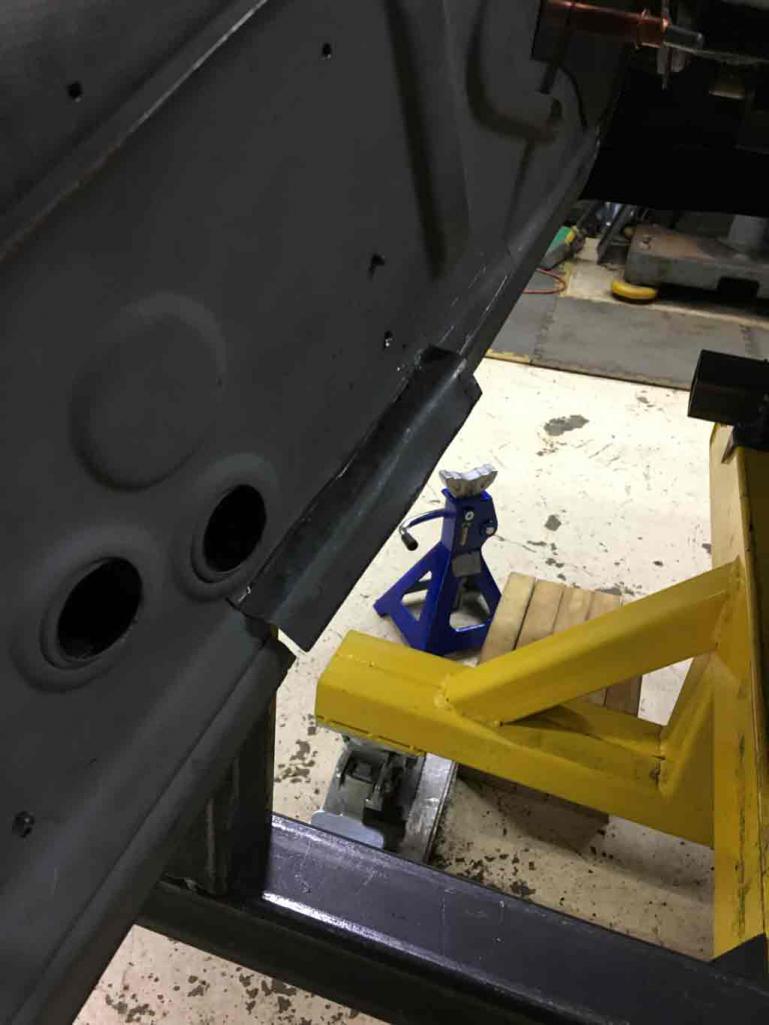
Once the part was correctly positioned I used a body hammer and dolly to return the flange to mate with the part and then welded the flange back where it belongs. In the photos below, I still need to add a doubler reinforcement on the inside to replace the material I removed. 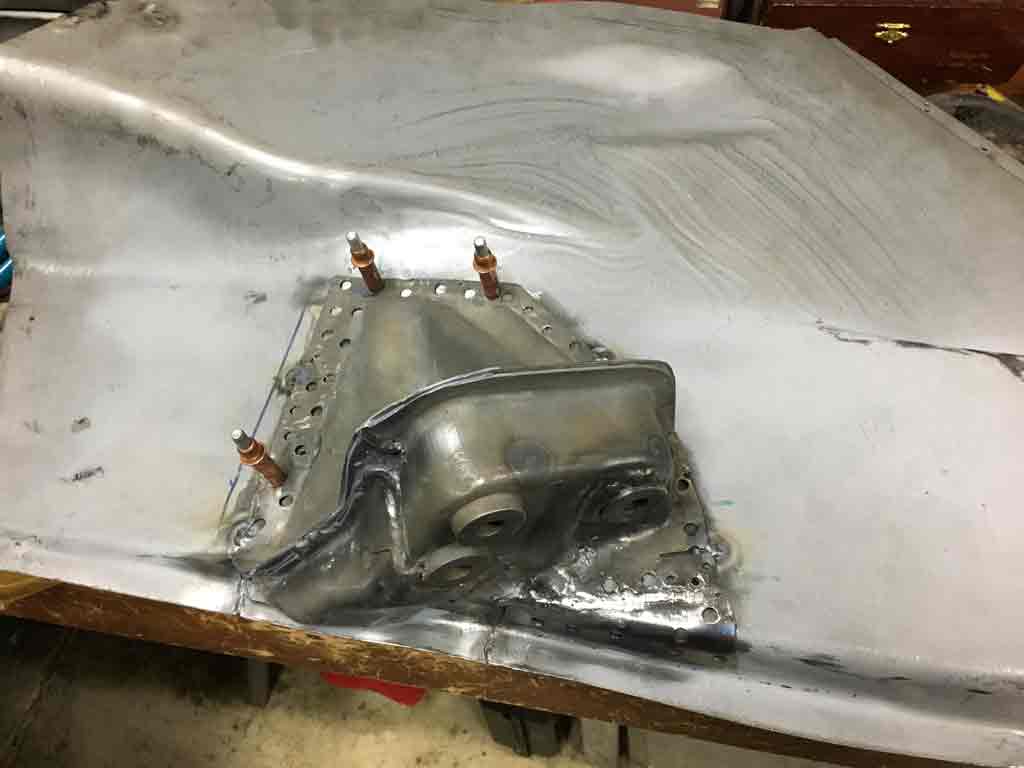
put the panel back into the vehicle and reconfirmed my measurements. All in all I'm pretty happy. When everything is metal finished and painted, the modification won't be evident and will be as structurally sound as the unmodified panel. 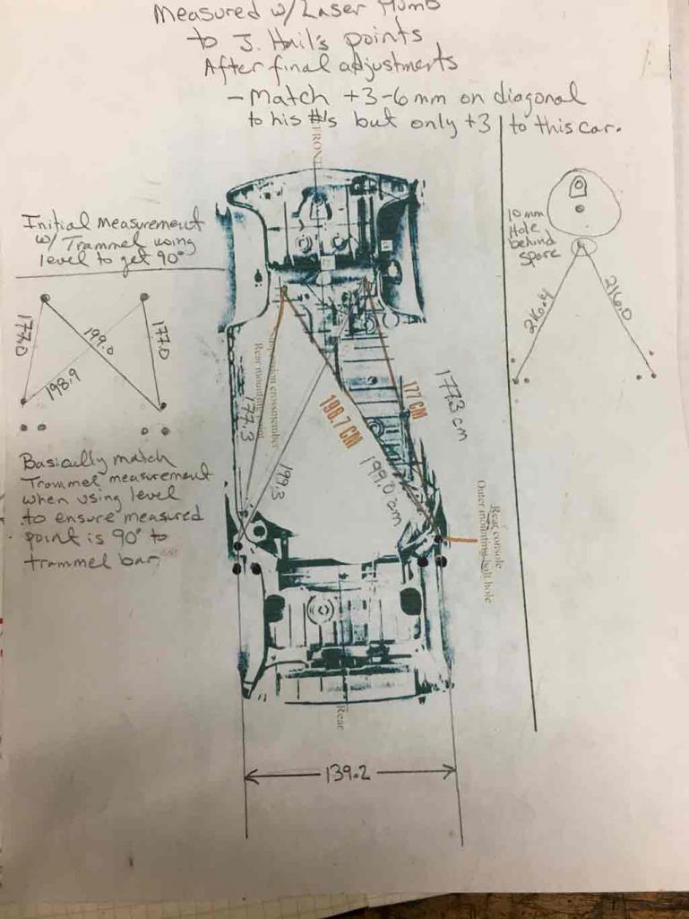
I'm still off on the diagonal by a 3mm (~ 1/8") but that can be adjusted when I instill the inner section of the frame that resides in the engine bay.
Looking forward to moving on!! I know fitting the inner frame rail is going to be time consuming based on the rough fit work I had to do already.
Once that is done, I hope to make more rapid progress. February is here and it takes forever to heat up the garage in order to accomplish any work! 
Still have lots to do!
Posted by: Superhawk996 Feb 9 2019, 06:24 PM
Back to work. Last couple of weekends have been limited work due to other priorities and some ridiculously cold weather.
Back to mocking up pieces to tweak fits. First order of business was to get the inner frame mated to the outer wheel house and to the fit up the connection at the rear trunk.
In my case I found that the outer house sheet metal which as a doubler welded to it was causing the inner to sit too high. I did some creative reforming with a hammer and dolly and got it down to the point where the angle of the two frame rails is within 1 degree of each other. 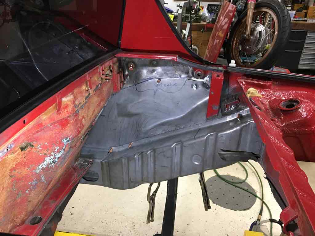
I then started to mock up the inner longitudinal. This one is a bit surprising that the sheetmetal overlap between the inner frame rail in the engine compartment only overlaps the inner longitudinal by about 1/4". That just isn't going to do. That joint will be too weak and it's right at a highly stressed location.
I'm considering welding in a good 6" of overlap and then installing the whole inner longitudinal + the engine compartment inner all as 1 big piece. 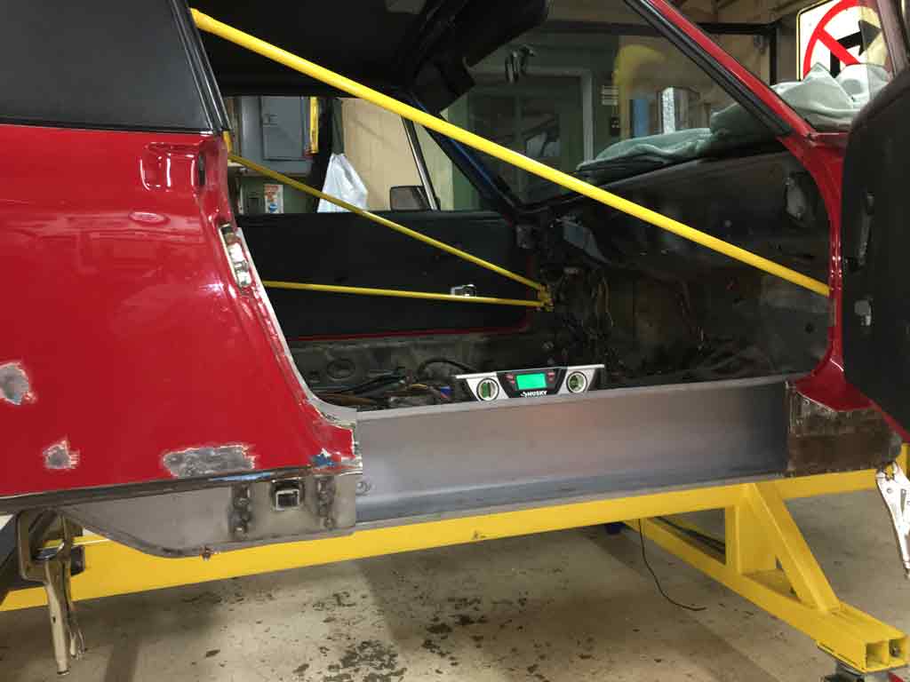
Overall, I'm pretty happy to see something roughly resembling a "frame" back under the car even if it's only a mock up. It will likely be a while before I can weld. I have quite a bit of pin hole rust up in the front wheel wheels that needs to be fixed before I weld in structure.
Question: Does anyone know why the AA inner longitudinal has two seat belt bolts? My driver side and the cutout part only had one. I can't see the point in this. I'm likely to cut the 2nd out and fill the hole so that I only have one like the original. 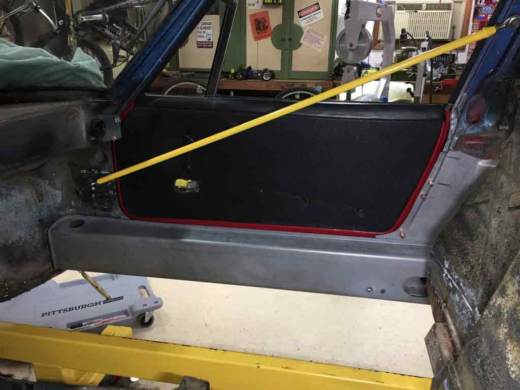
Posted by: R8CERX Mar 1 2019, 02:19 PM
WOW--AWESOME work!!
Cant wait to see end result!
Thanks for the advise!
Felix
Posted by: Superhawk996 Mar 15 2019, 09:45 PM
It's been a while since I posted. Things have a way of getting side tracked. 
Posted by: Superhawk996 Mar 15 2019, 10:08 PM
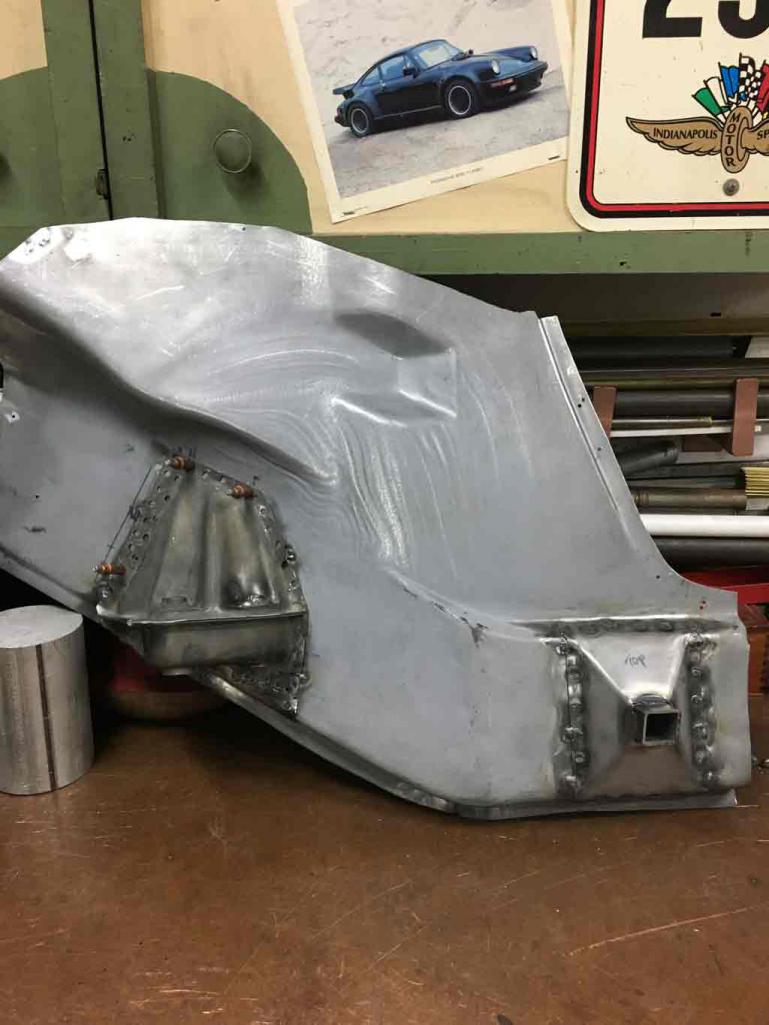
Although I had a rough mock up there is still more work to do on the wheelhouse inner panel.
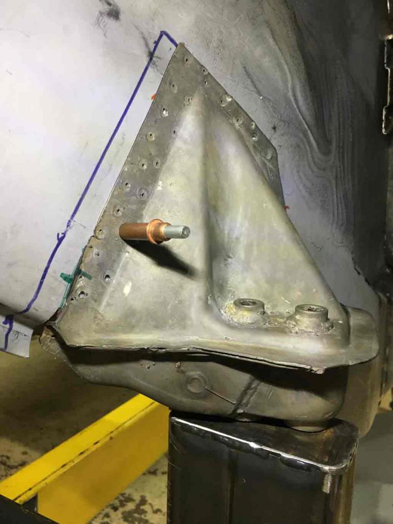
I finally decided to commit to final welding of the outer trailing arm mount.
I plan to add the Restoration Design outer clam shell to reinforce the whole outer longitudinal.
The problem is I'm not cutting my fender so all work has to be done from the "inside". This means that I can't assemble the whole longitudinal and then go back and add on the clam shell.
Much scratching of the head resulted in the decision to deconstruct the clam shell so that it can be added in pieces rather than one whole piece. The other thing is I don't like how the added layer of metal will push my existing door jamb outboard. I'll try to post picture of this as I go along. Hopefully the pictures will make things more obvious.
Here is the picture of just the rear section of the clam shell reinforcement in place. I feel that this piece is especially important since it adds another layer of metal to the transition area. This area where a lot of stress occurs and this area of the "frame" is weak since this area is where the inner longitudinal panels meet.
Even if I decide later not to add the rest of the clamshell for some unforseen reason, I feel that having a triple layer in this high stress area is time well spent. 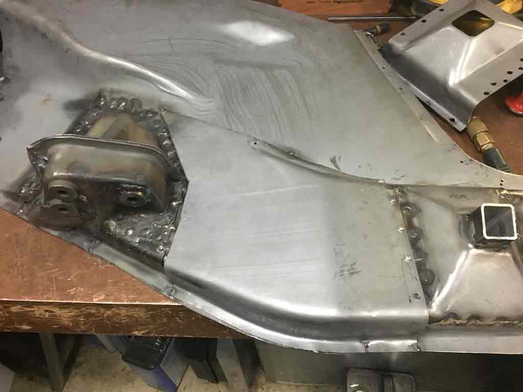
You can see the overlay for the jack post with the spot welds drilled in the background. I'll eventually install that but it needs some trimming to avoid pushing out the door jamb.
Welded in place. 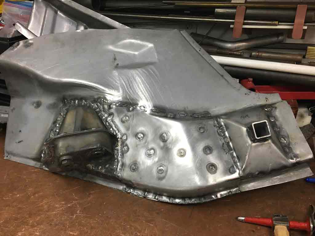
In the process of final welding I did get some warping of the panel that needed hammer and dolly work to put things back in the right place so the inner longitudinal in the engine compartment will fit as it originally did.
Likewise, this will require re-measurement all the way around the chassis again before I can put this panel in place for the final fitment.
During this whole process the Galvanneal steel is giving me fits with a TIG welder.
The zinc that is in the Galvanneal is constantly contaminating the electrode or causing popping that splashes the weld puddle up onto it. 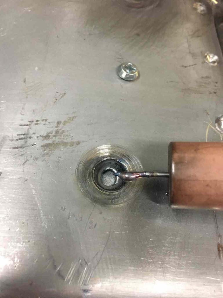
The only good thing is the constant stop / start to regrind the Tungsten helps avoid overheating the panel.
Posted by: Superhawk996 Mar 15 2019, 10:19 PM
The other thing that has derailed my effort to get the long in place is that the Tin Worms have consumed the lower 1" of just about the entire perimeter.
I suspect that someone repeatedly left the Targa off this vehicle and it got filled with water. leading to all the corrosion on the lower 1" of the entire floor pan. 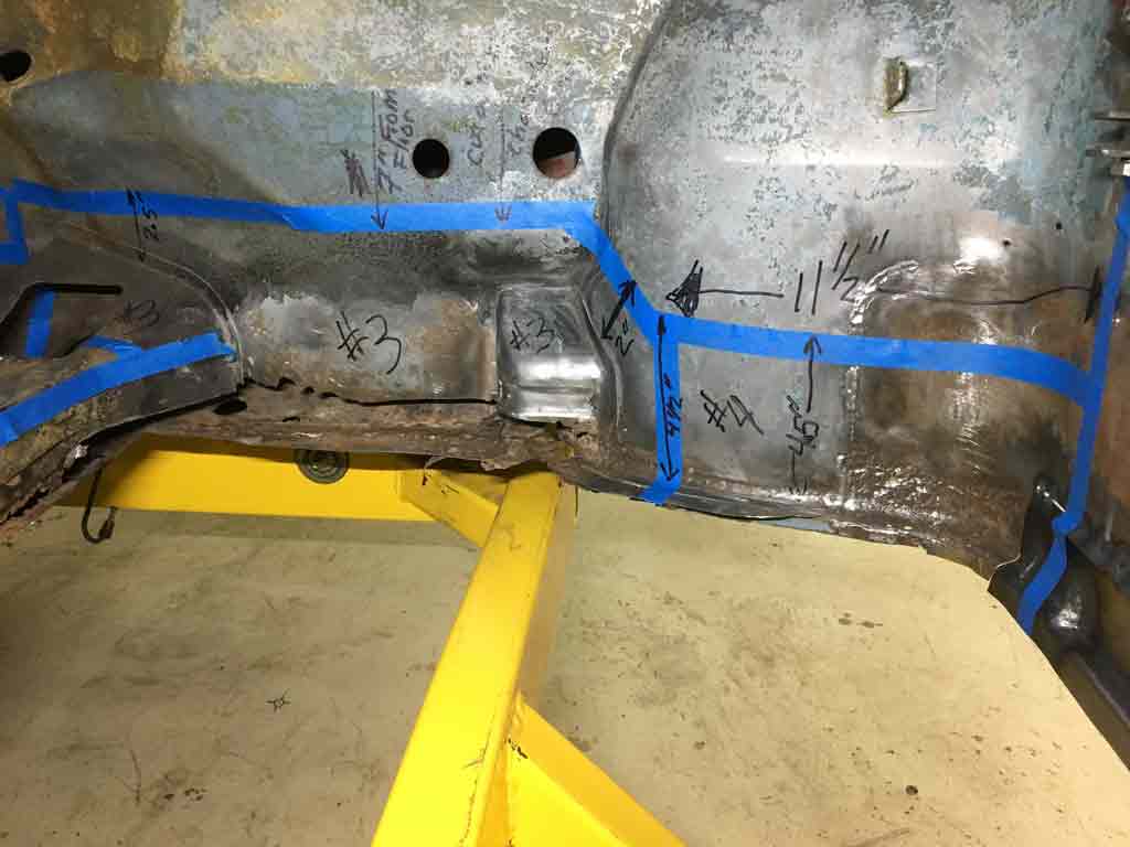
So before I can weld in the longitudinal I need to get some solid metal back in the lower cowl and wheelhouse area.
I started to fabricate the lower couple inches of the longitudinal outer. 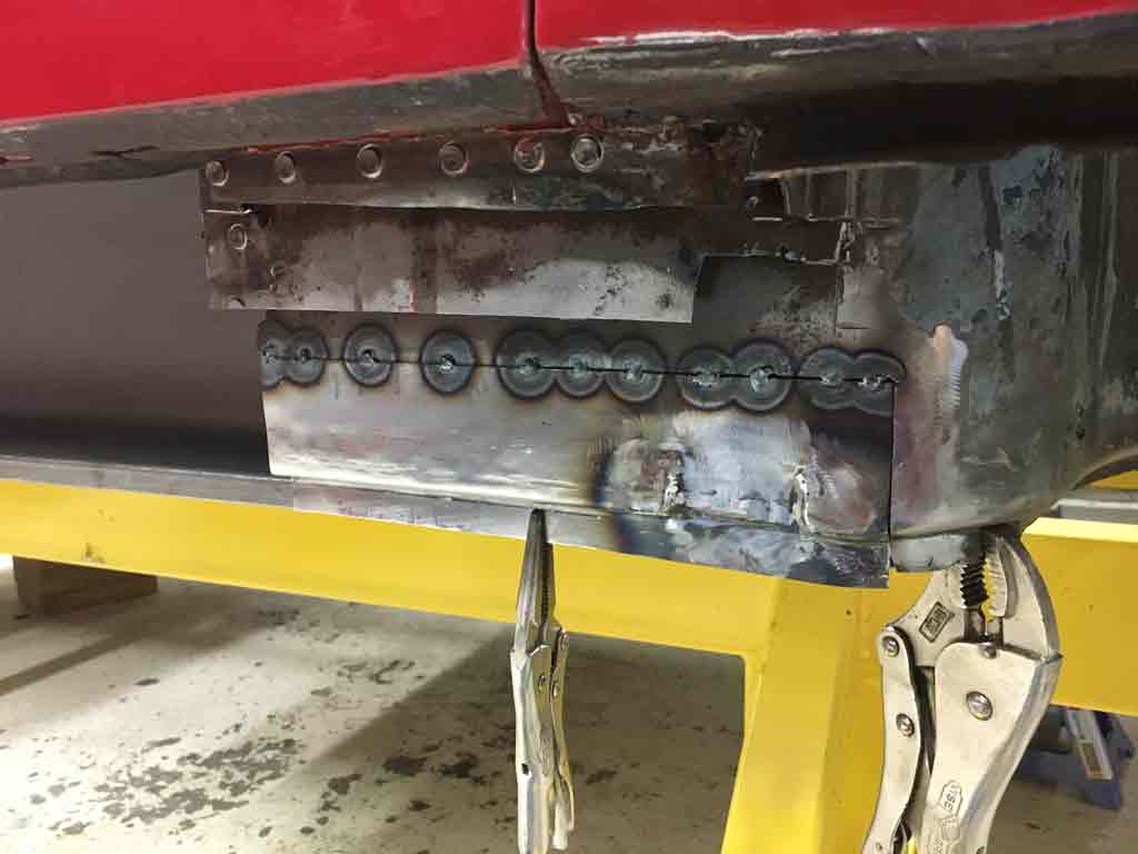
But the more I got to thinking about doing a from scratch fabrication I decided to see if I could find some donor sheet metal. The tight radius bends and the compound curvature of the wheelhouse weld flange was just going to be agonizingly slow to do from scratch.
Posted by: Superhawk996 Mar 15 2019, 10:32 PM
@http://www.914world.com/bbs2/index.php?showuser=7898
Came to my rescue and provided a whole front lower cowl as a donor. I can't say enough good things about Vince!!  His prices are reasonable and he was willing to help ensure I got sound metal and the right cuts to work with my need.
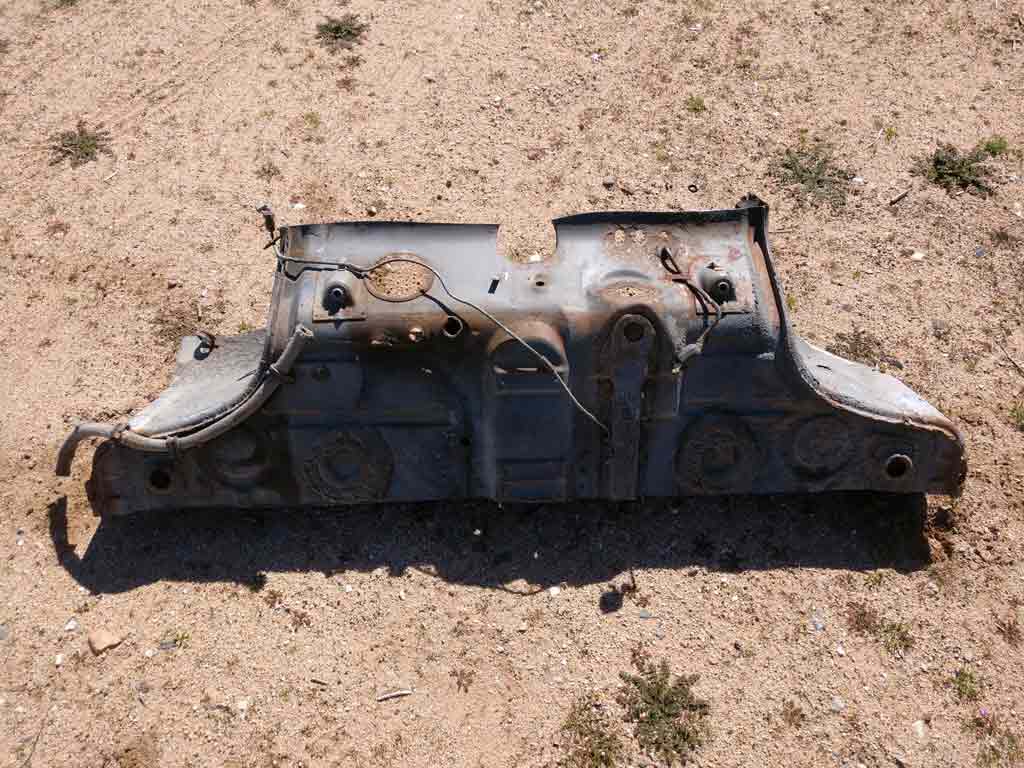
The time it takes to deconstruct stuff is amazing. Lots of drilling spot welds and maybe some profanity is the order of the day. 
Piece by piece I finally started getting to the individual panels I'll eventually need to piece this all back together into my vehicle. 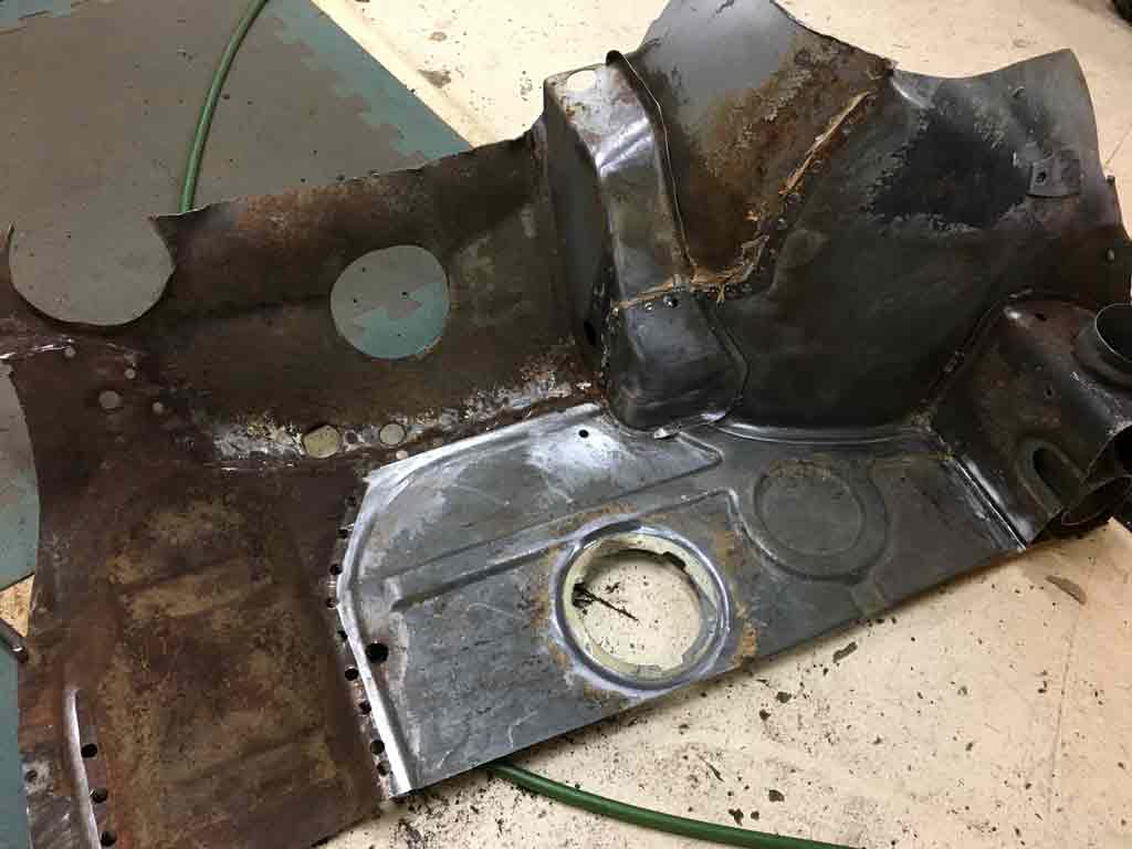
Posted by: Superhawk996 Mar 15 2019, 10:37 PM
I'll end up with some odds and ends that I won't be using.
If anyone is in need of the front tunnel section or the floorpan plug (previously filled empty hole) let me know and I'll pay it forward by sending to you for cost of shipping only.
With a little luck, I'll get a chance to start cutting out the bad metal on my tub and start fitting up this new donor sheet metal.
Posted by: bbrock Mar 15 2019, 10:41 PM
But the more I got to thinking about doing a from scratch fabrication I decided to see if I could find some donor sheet metal. The tight radius bends and the compound curvature of the wheelhouse weld flange was just going to be agonizingly slow to do from scratch.
That area gave me fits for the reason you mentioned. I got plenty of practice making multiple attempts until I got it right. Donor piece is the way to go.
Looking forward to seeing more about how you tackle that rear wheel house and long without cutting the fender. I'm really enjoying watching the quality work.
Posted by: Superhawk996 Mar 15 2019, 10:44 PM
@http://www.914world.com/bbs2/index.php?showuser=20845
You've set a pretty high bar. I'm just trying to keep up.
Posted by: mgphoto Mar 17 2019, 10:11 AM
Question: Does anyone know why the AA inner longitudinal has two seat belt bolts? My driver side and the cutout part only had one. I can't see the point in this. I'm likely to cut the 2nd out and fill the hole so that I only have one like the original.
I bought the same part through Sierra Madre collection, it only had the single hole.
I bought it about 3 1/2 years ago. It was a challenge to install, you’re doing great, do you have a picture of the long from outside of the car?
Posted by: Superhawk996 Mar 17 2019, 10:20 AM
@http://www.914world.com/bbs2/index.php?showuser=10225 Nice project photo. I love seeing the rest of you guys that are tearing into and fixing up cars that would otherwise get scrapped.
Not sure what you mean on the photo? Are you looking for a specific shot or angle. I will photo what ever I can to help you out.
Thanks for confirmation of one hole on other aftermarket longitudinal parts!!!
Posted by: mgphoto Mar 17 2019, 10:41 AM
I would like to see a photo of your car sort of the same as mine, I want to see the position of the second hole.
Posted by: Superhawk996 Mar 17 2019, 11:42 AM
I would like to see a photo of your car sort of the same as mine, I want to see the position of the second hole.
@http://www.914world.com/bbs2/index.php?showuser=10225
Here are two views. I can't get the innerwheel house / jack support out of the photo that is what currently holds it all in the car.
If these photos don't help I can take a picture of just the long with a tape measure.
My thought is the 2nd hole might have something to do with the early longitudinal on passenger side that had a fixed passenger seat and may have had the belt in slightly different spot.
The other more cynical view is that in the 1970's we were all much thinner and maybe now we are all running out "Belts" out a few more notches than we used to?
Posted by: Superhawk996 Mar 17 2019, 11:45 AM
Photo of passenger side donor sheet metal rough trimmed & sandblasted.
Still need to fix a few of the holes from drilling spot welds and then will do a quick dip in metal prep. 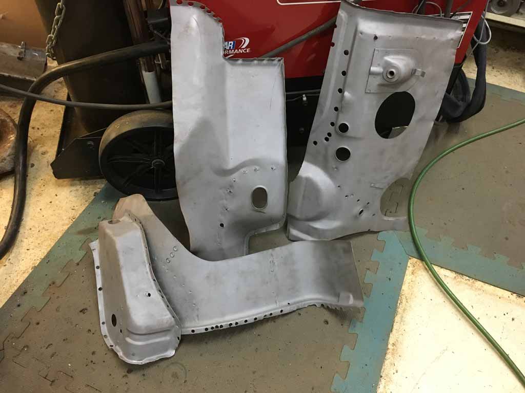
Posted by: bbrock Mar 17 2019, 12:20 PM
My thought is the 2nd hole might have something to do with the early longitudinal on passenger side that had a fixed passenger seat and may have had the belt in slightly different spot.
The other more cynical view is that in the 1970's we were all much thinner and maybe now we are all running out "Belts" out a few more notches than we used to?
Early vs. late is the only thing I can think of, but I think your "Fat Ass Hypothesis" has merit. I concur that factory only had one hole but have no idea if they changed the position when they moved to movable passenger seats and American butts got bigger.
Posted by: mgphoto Mar 20 2019, 11:54 AM
I would like to see a photo of your car sort of the same as mine, I want to see the position of the second hole.
@http://www.914world.com/bbs2/index.php?showuser=10225
Here are two views. I can't get the innerwheel house / jack support out of the photo that is what currently holds it all in the car.
If these photos don't help I can take a picture of just the long with a tape measure.
My thought is the 2nd hole might have something to do with the early longitudinal on passenger side that had a fixed passenger seat and may have had the belt in slightly different spot.
I don’t think so, I think the original mount was welded in the wrong place. It looks like the seatbelt mount might be to close to the bulkhead for it to swivel cleanly.
Take your original carpet and see where the holes line up.
Although I might not weld it up, it does leave an access hole. When I started, I got advice from a number of people on this board, one was Brad 914ltd, he said “belt and braces” paint the inside of the long and use cavity wax after assembly.
The original longs have a rubber patch which covers the holes. The extra hole might be useful.
Posted by: Superhawk996 Apr 6 2019, 04:17 PM
Time to post a little progress for March.
Here is the problem: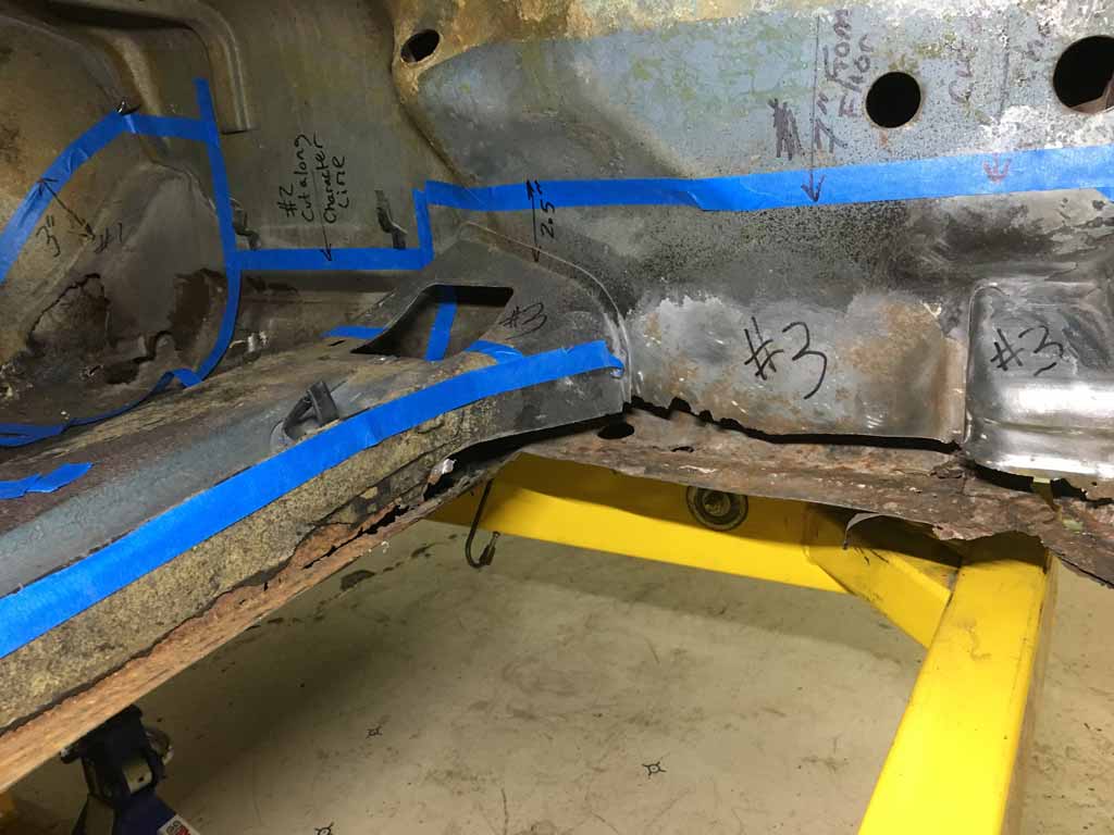
Everything starts with the simple task like getting ready to fit up the inner longitudinal. But then you have to deal with the fact that the metal it's supposed to mate to has been consumed by the tin worm. Then you have to stop the original task and then focus on this new one before you can do the main task. That is the way rustoration goes.
I took 3 vacation days from work that butted up to a weekend and went to town.
So with my newly prepped donor parts it's off to the races. Let the cutting begin.
First victim - getting rid of the rear steering rack mount on the passenger side. Like the rear suspension console, it came to me "pre-stripped" by the previous owner. That didn't really matter though because the sheetmetal was shot.
Tunnel was also removed. Like all the other metal, it is shot at that transition between to the floorpan. I got tired of getting a kink in my back attempting to work around it & scratching my back on it! Good riddance.
A donor tunnel has been sourced - we'll deal with that later 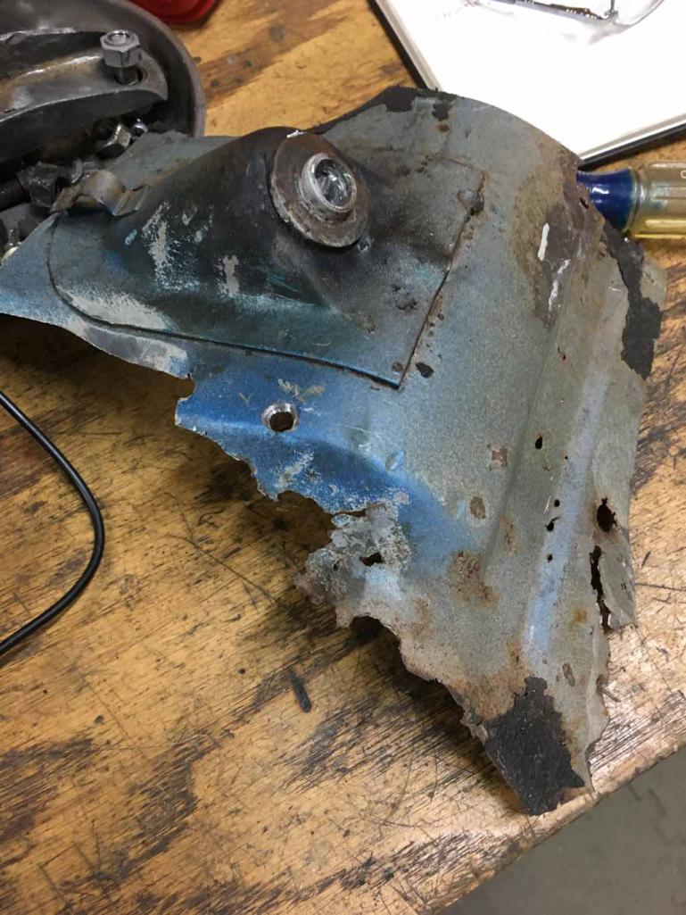
This car must have flexed and been as loose as the dickens given that the upper body sheetmetal is separated from the lower by rust though on the lower 1" all the way around. I often wonder how people don't notice chassis flex. 
Garbage metal on the back side of the rear rack mount; absolutely no structure left here 
The donor metal I obtained was then fitted in on the passenger side floor 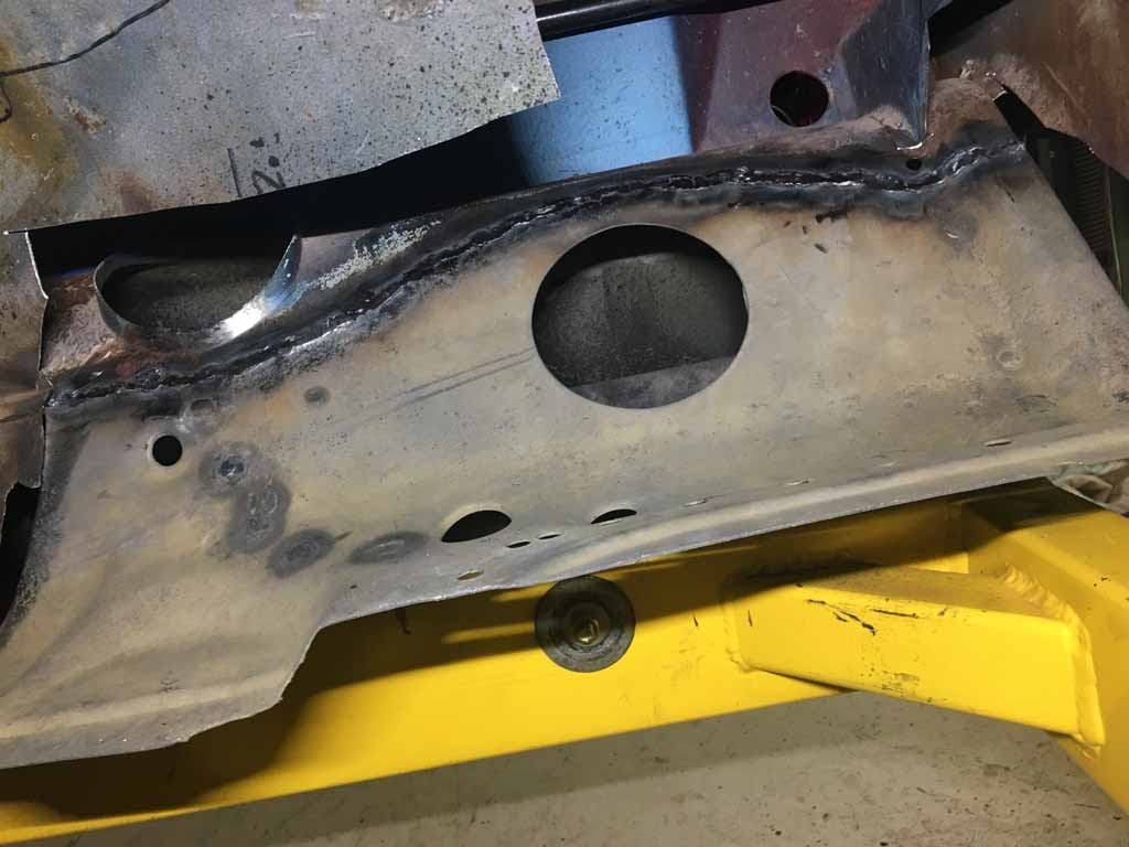
Then moved on to reworking the passenger side wheel wheel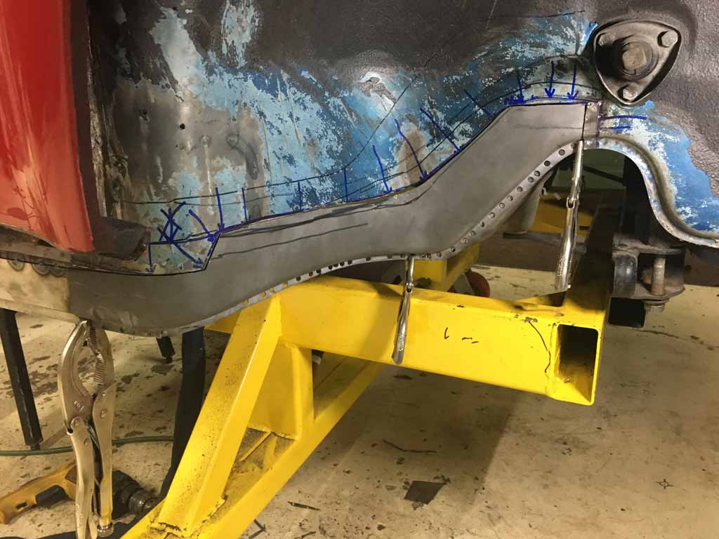
With that metal in place moved on to fixing the "frame" extension that comes in to the passenger compartment from under the fuel tank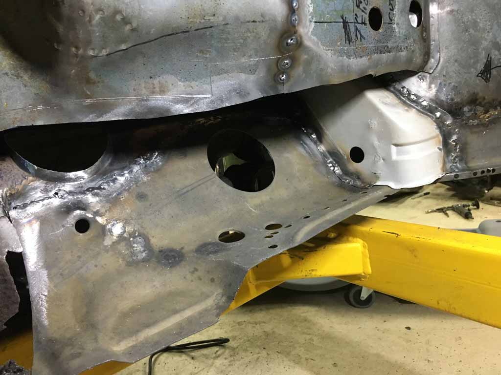
View from the Frunk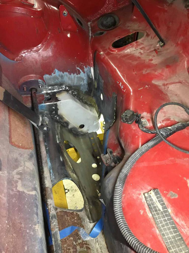
Spent some time fitting in the lower cowl and then returning my upper cowl access flap to its home. 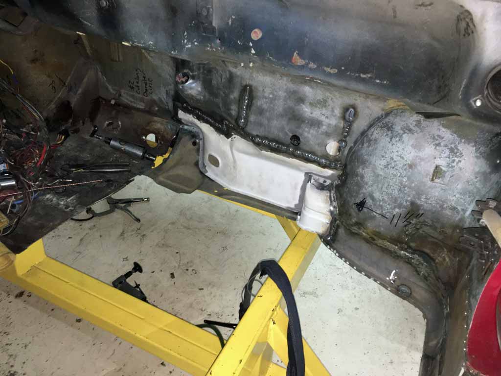
Although I'm making progress, I'm a well behind where I hoped to be by April. I think I'm about two months behind at this point. I would really like to keep this project contained to 1 winter season for the sheetmetal work but it's getting dicey. Not sure what I was thinking. 
Gratuitous Parts Porn: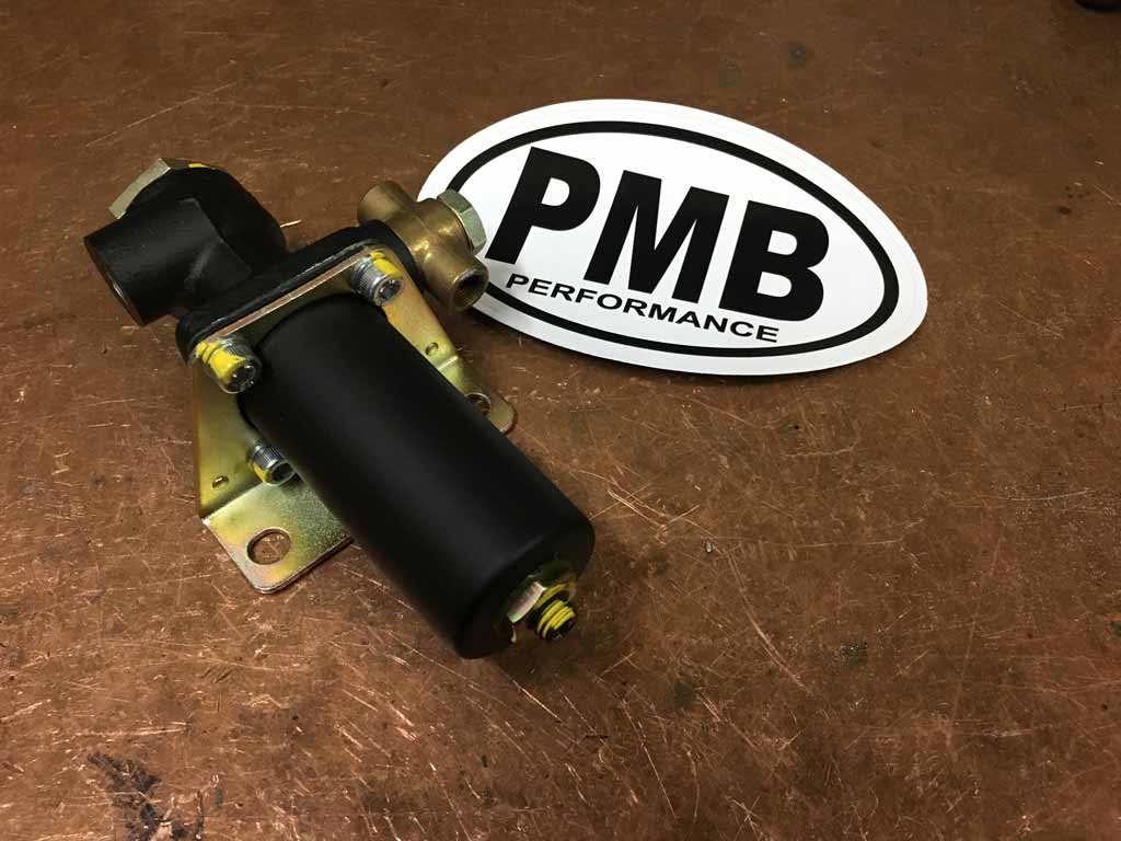
Got my proportioning valve back from restoration by PMB. Beautiful.
@http://www.914world.com/bbs2/index.php?showuser=1110
Posted by: bbrock Apr 6 2019, 06:02 PM
Just your mark-up is a work of art. That's quite the puzzle you are piecing back together! I think your car would have defeated me. Incredible work. 
Posted by: Superhawk996 Apr 6 2019, 06:26 PM
Just your mark-up is a work of art. That's quite the puzzle you are piecing back together! I think your car would have defeated me. Incredible work.
Please. . . I cheated and used donor sheet metal to do the wheel well. I can't imagine how you had the patience to do those compound curves from scratch.
Posted by: Superhawk996 Apr 6 2019, 06:35 PM
I was saving my effort doing complex metal forming for motorcycle projects that are currently on hold while I do the 914.
Wife no longer willing to ride on the back of motorcycles.
Started this Norton Commando cafe in 2012. Metal fab still stuck at this state although I did get the engine and trans rebuilt and added into the mock up. 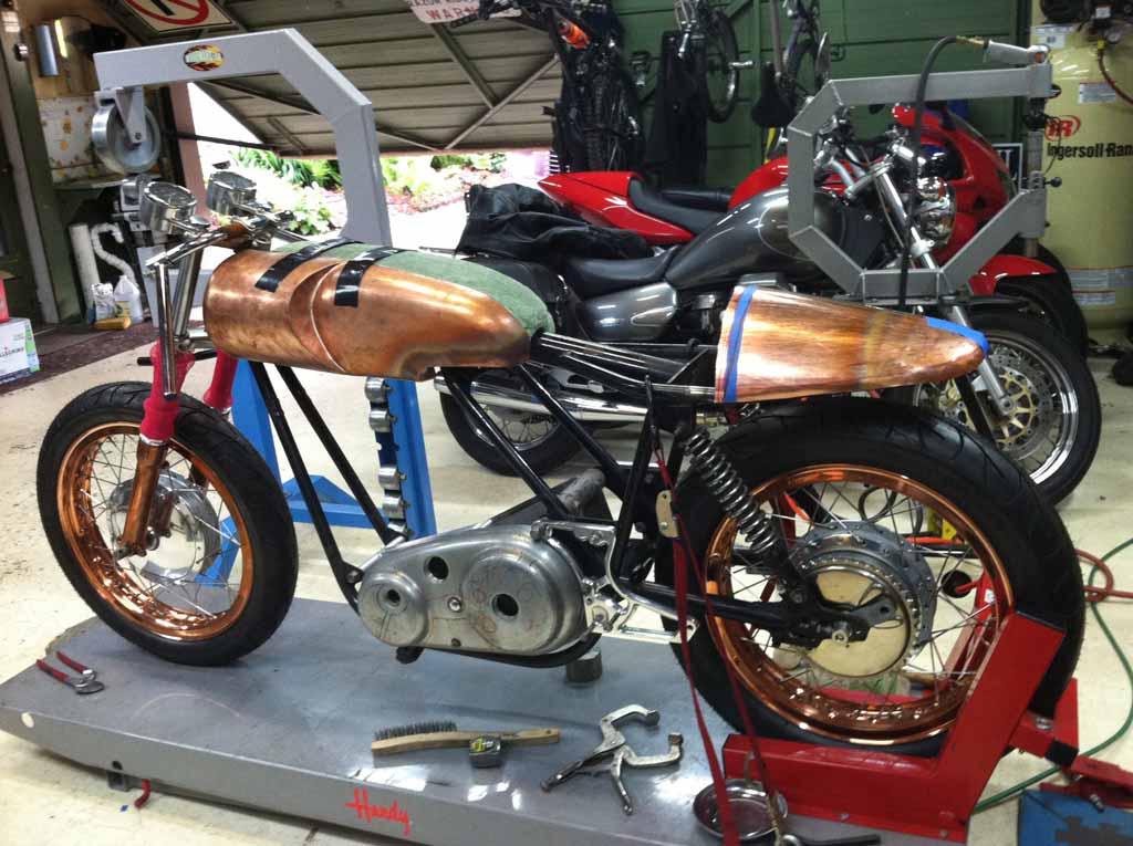
Previous aluminum tank of similar design. 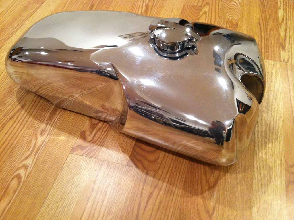
Posted by: Superhawk996 Apr 23 2019, 07:31 AM
Been a little bit slow posting lately. Spring and yard work and honeydew list is competing for time.
Today I'm at the butcher having bits of of my face carved up to remove some minor skin cancer. The good news is I can catch up on my posts between butchering sessions.
I am still working on the passenger side cowl to get that fixed up.
Here is a before & after view.
Attached image(s)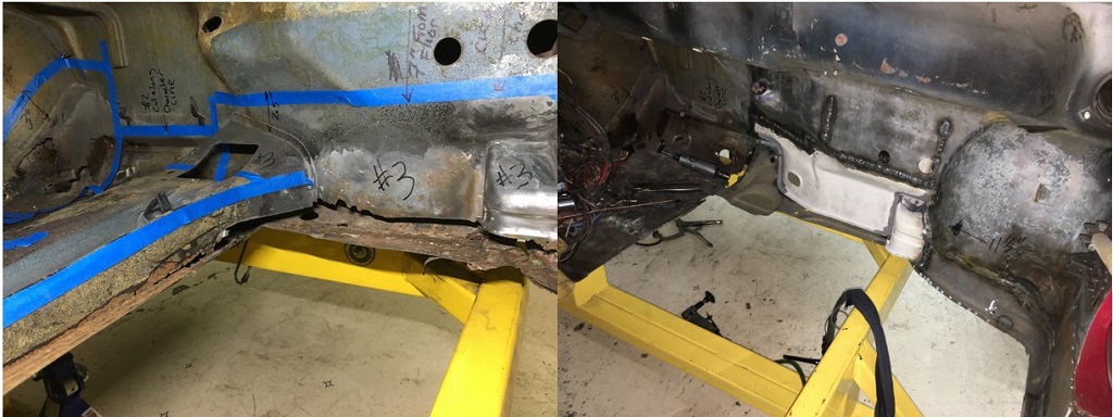
Posted by: Superhawk996 Apr 23 2019, 07:52 AM
This cowl area has taken way too much time.
A few lessons that I've had to remember the hard way. I knew better but sometimes you get in a hurry and try to shortcut things. It rarely works.
1) Panel fit up is paramount. you have to have gaps that are 1mm or less to get a nice weld.
2) Use lots and lots of tack welds. Don't leave big gaps between the tacks. This helps eliminate warping and more importantly as the tacks increase in number, it yields more heat transfer paths to prevent burn through. When you think you have enough, double it!
3) Do very short welds between the sport welds with minimal filler. if more filler is needed its easier to add more later.
I disregarded all three of these points and have regretted my choice!
I initially mis-trimmed the lower cowl a little bit under size. This lead to a 2-3mm gap. I should have just closed the gap up to 1mm and then had to bend the flanges down to the floorpan to make up for it.
Instead, I fitted the flange to the floorpan and then let the gap be 2-3 mm. This was a critical mistake. Trying to fill a gap this large is just asking for trouble.
I then did a awful lot of tack welds to bridge the gap . . . but not enough. I began to rush the job and wanted to get er' welded up. When I tried to close the open spaces between the tack welds I just ended up burning holes. This cowl sheet metal is only 0.036" thickness. Not very tolerant of being overheated.
To further compound my mistakes, I ended up having to add lots of filler rod to keep from burning holes. This leads to big booger looking welds and the need to grind welds which is very time consuming.
I then went back and ground down all the excess filler only to rediscover lots of pin holes that didn't fully fuse due to the large gap between the panels and the rapid addition of filler.
Then tried to fill the pin holes and proceeded to blow more holes now that the weld was thinned excessively. This was a viscous circle.
At some point you just realize you are making a mess and need to stop the madness.
It took several welding sessions just forcing myself to slow down and to fix my mistakes as best I could. Ultimately I ended up putting a light in the gas tank area so I could see the pin holes and then carefully filled them.
Posted by: Superhawk996 Apr 23 2019, 08:15 AM
The other thing that led to rushing the job was all of this welding is out of position welding and needed to be done with me sitting or kneeling in uncomfortable positions on the floor while working in this area.
Nothing leads to rushing more than being uncomfortable.
The other key thing is that is worth repeating is you can't weld what you can't see. some positions that I was forced into obscured my visibility to to the weld puddle. Not being able to see the puddle is a great way to let it get too hot and to burn through.
To top all this off, my cowl area has an abundance of holes (other than rust) that needed to be fixed.
1) A/C holes were cut for lines to pass through.
2) Sheet metal screws were randomly punched though the cowl area to support the A/C unit itself under the dash.
3) whenever a previous owner wanted a ground connection, they just shot another screw though the cowl.
I've started to address the large A/C line holes. The only problem here is this is overhead welding. Even more fun! 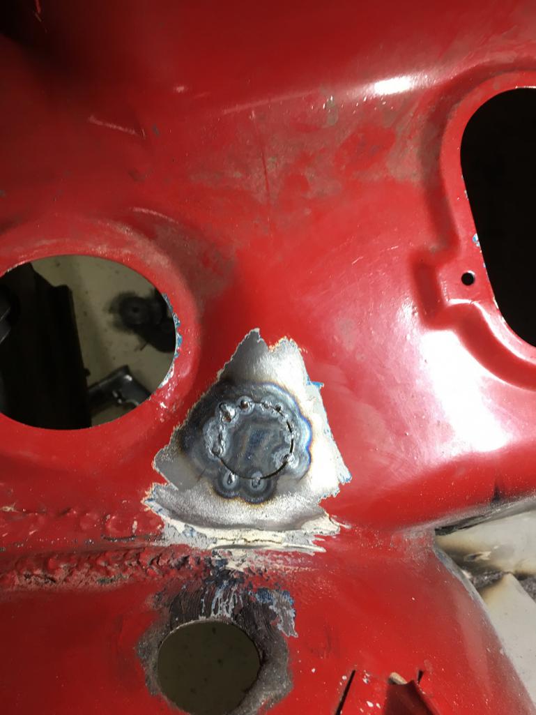
These holes are tucked right into the corner of the cowl & fender area.
I tried to weld this in from above but my welding helmet prevents me from getting my face in a good position to see the weld puddle. You can see this by the tack weld at about the 7:00 position of the hole -- completely missed the weld gap! Cannot weld what you cannot see! . I resorted to doing the other tack welds from inside the passenger compartment and from below.
I don't like this solution. I think my next try will be to use a gas lens and hang my Tungsten as far out as I can hoping to get better visibility to the weld. Trying to be slow and patient and find the best welding position to do this. If I start blowing holes in this area I'm screwed.
Posted by: tygaboy Apr 23 2019, 08:32 AM
 with all the "can't see = can't weld". I'm living some of that now, too.
From my experience, I will say that in some of these situations, I've found MIG is my friend (vs TIG) in that it was easier to find a workable position, I didn't have to worry about how to work the pedal or find room/see the filler rod.
If I could TIG everything, that would be my preference but...
Your build is looking great, btw. Really nice work!
Posted by: Superhawk996 Apr 23 2019, 08:35 AM
These are the easy ones. Just a quick dab or two of filler to weld up the sheet metal screw holes. 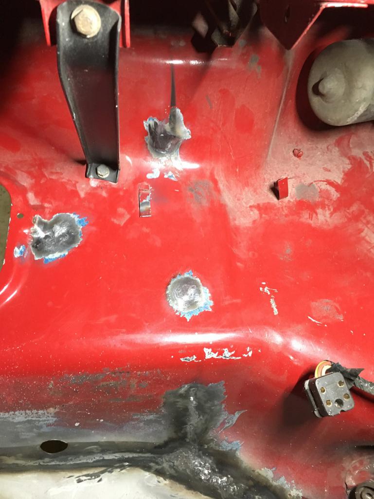
In just this photo, there are 3 holes! There are more on the driver side and one of them is about 0.5" diameter. I'm not sure what was run though that hole but is just the right size to be a a PITA.
1) it's behind / above the fuse block which will necessitate removal of the fuse block and wiring to access it.
2) 0.5" is just big enough that you can't easily trim a metal blank to fill the hole and therefore you just have to fill it by gradually adding filler around the perimeter of the hole until it can be closed up.
Can't wait to get to that one. I'll defer until I start working on the driver side of the car.
One point that I wanted to make as an engineer to those that might be thinking why worry about a few little holes. Don't forget that just in front of you is the gas tank. In a worst case crash / fire type accident, you don't want holes in the front cowl that could easily allow fuel and fire to enter the passenger compartment.
I know that the plastic vents and paper heater tubes won't last long in a fire but they do buy you seconds to minutes of time. a big 1" hole like one of these A/C hose pass through holes would allow fuel and/or fire access to the passenger compartment completely unimpeded.
Better safe than sorry!
Posted by: Superhawk996 Apr 23 2019, 08:48 AM
with all the "can't see = can't weld". I'm living some of that now, too.From my experience, I will say that in some of these situations, I've found MIG is my friend (vs TIG) in that it was easier to find a workable position, I didn't have to worry about how to work the pedal or find room/see the filler rod.
If I could TIG everything, that would be my preference but...
Your build is looking great, btw. Really nice work!
@http://www.914world.com/bbs2/index.php?showuser=19241
I'm a TIG lover due to the flexibility to weld so many types of metal and for the control it offers. If I burn holes I can't blame the equipment - It's my fault.
But boy is it slow for this type of work! Every week I contemplate buying a MIG but I haven't rationalized it yet. I do think that if I do I would sell it once this is done and try to recoup some of the cost.
For you other TiG lovers, I have to plug this product. It is a pressure sensitive Amptrol. No need to move finger to control amperage - just press harder or lighter.
I really haven't done much out of position TIG welding in the past. Most of it has been on a nice comfortable bench. I couldn't live without this.
When I first started to weld up my build cart, I was using my standard footpedal and doing all sorts of Yoga to try to weld and control the pedal with my knee, leg, elbow or whatever. I was pretty much impossible and led to the purchase of the TIG button.
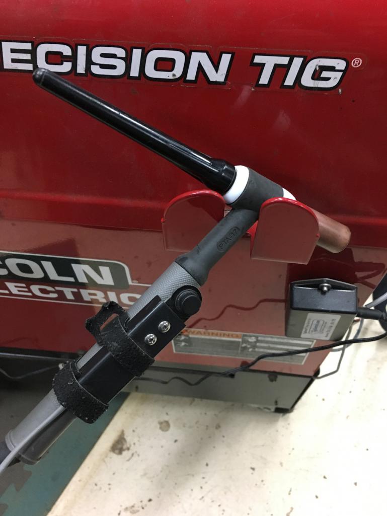
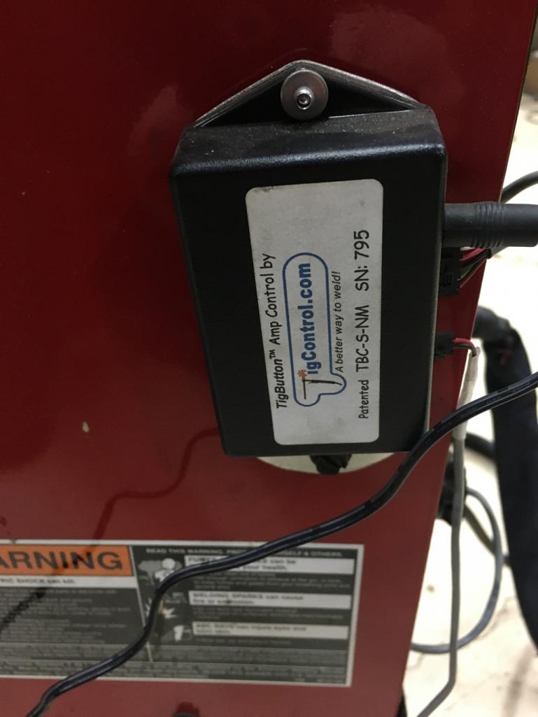
http://www.6061.com/tigbutton.htm
Posted by: Superhawk996 Apr 23 2019, 09:04 AM
The other work that has started in April is beginning to think about what to do with my engine.
As purchased it was setup with carbs. I've been thinking about returning to fuel injection.
As part of that I pulled the tin to see if the cylinder head temperature (CHT) sensor was still there.
As the subject of another thread, I found that the CHT is missing and even worse, the head isn't drilled and tapped for the CHT. It isn't on the cyl 1/2 side either. Apparently at some point the heads were swapped.
Turns out that they are at least the proper 2.0L cylinder head as verified by part number. In the photo you can see the start of the proper 2.0L P/N 039 101 371A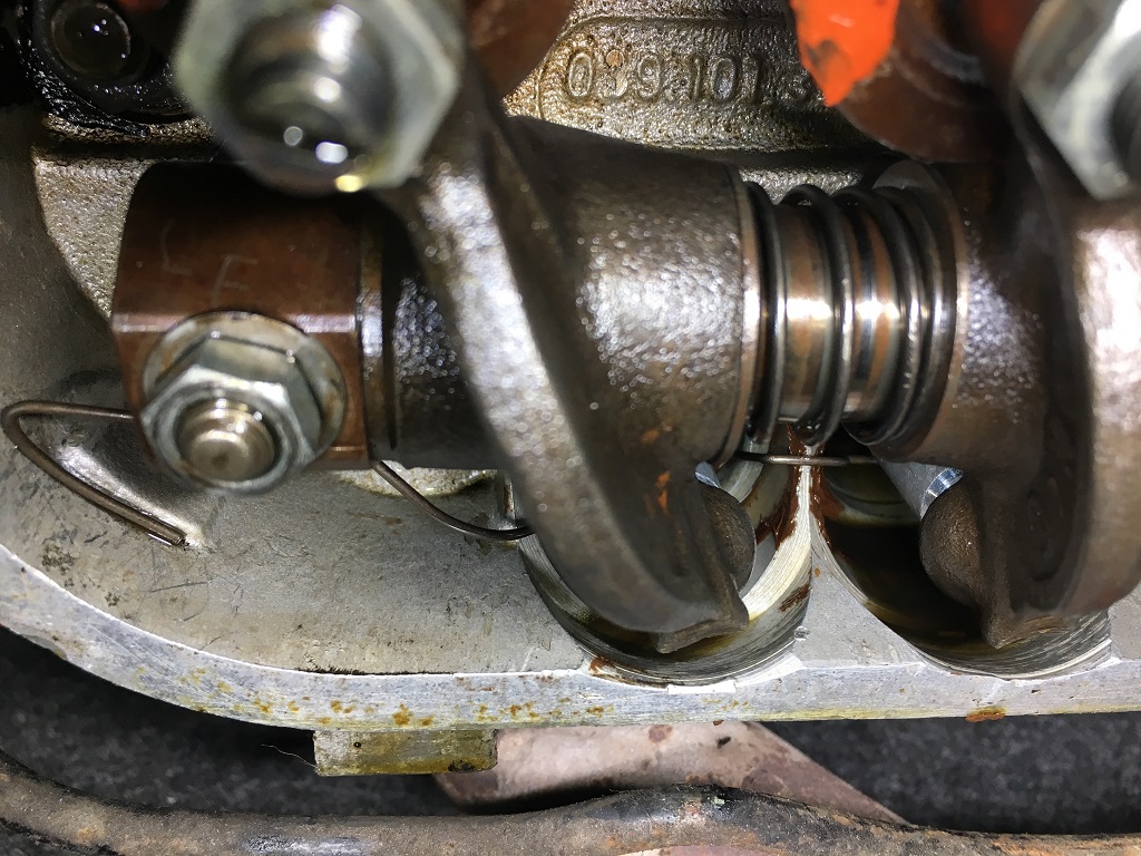
I pulled out my old broken 1.7L head from my original car just compare when I was in a panic thinking that they might not actually be a 2.0L head.
Also notice that some goober welded up the breather hole.
I guess I'll be doing some machine work! 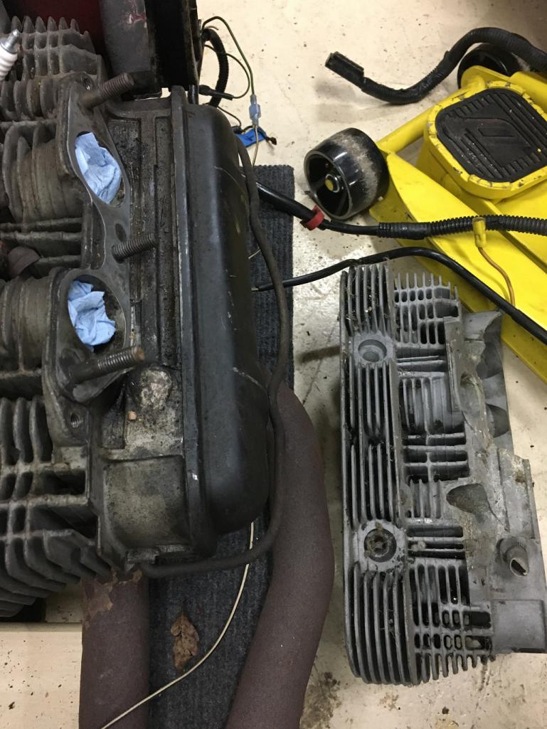
That 1.7L head was broken when my original 914 was rear ended. It has served as a learning bed for how to remove valves, valve guides, and how to weld cylinder heads! Still got some use again as a comparison to remind myself of what the difference looks like between 1.7L and 2.0L heads. My wife calls me a pack rat and can't understand why I would still have a cylinder head around from a car that was wrecked before the turn or the century.  Women!
I still haven't dug into the engine but fully expect that the cam has been swapped given that the heads aren't original.
My new engine yoke arrived yesterday.
@http://www.914world.com/bbs2/index.php?showuser=20845
Thanks for the recommendation and helping me save $$ on this item!
Posted by: Superhawk996 Apr 23 2019, 09:27 AM
Here is a bit of previous work. I removed the tunnel to better access the cowl for repair and because it was completely shot.
I figured it would be easier and a better repair to replace it completely rather than patch up what I had.
Here is the dissection to show it's internal condition. 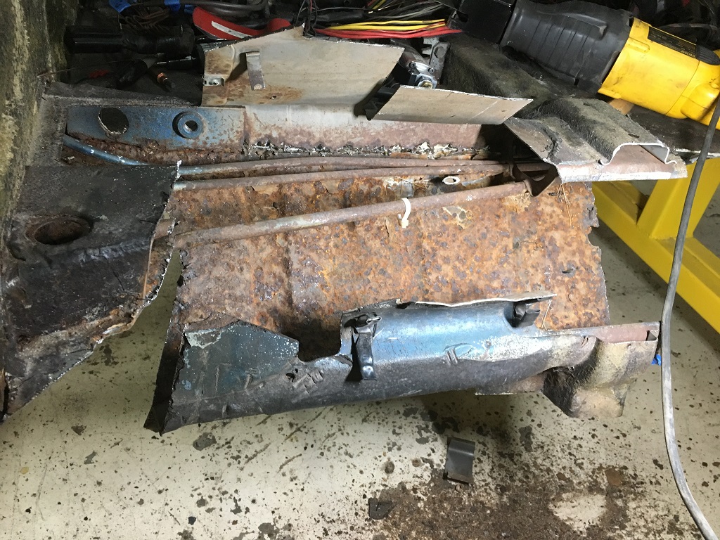
For any of you having problems removing and/or installing new throttle and/or clutch cables, don't rule out this possibility. 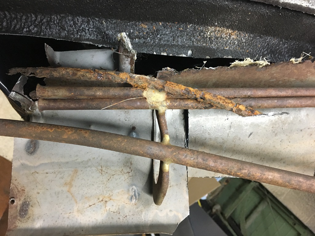
When I 1st was getting this car running, the throttle cable was stuck. When I pulled out the old cable, it hung up about half way out. I had to break it to get it out!
In order to get the car running, I cut a hole in the tunnel, and cut out a section of the tube and just fished the cable up to the pedal sled. It was a quick fix but wouldn't have been a good long term solution. The photo above shows why!
Posted by: Superhawk996 Apr 23 2019, 09:34 AM
For all you guys that think just a little rust in the floor pan isn't a big deal, here is what the bottom of the tunnel looked like from the outside. There is always way more rust than what you can easily see. 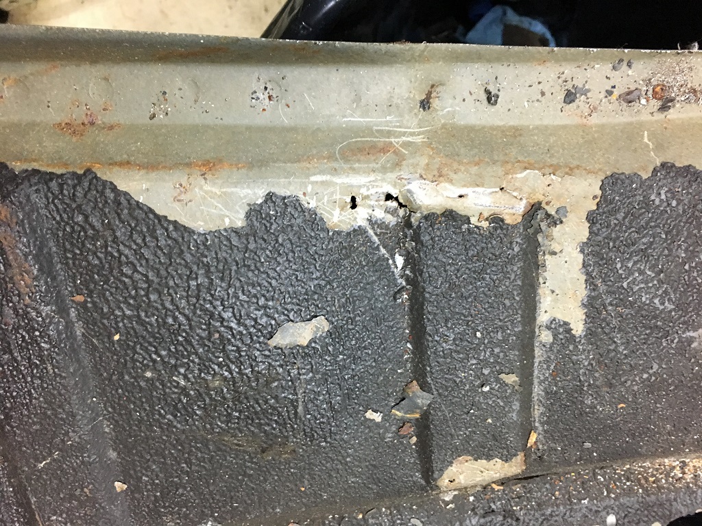
Random pin holes were hidden underneath the undercoating.
Not much of the previously shown damage was visible when I purchased the car but it was there none the less. Keep in mind how pretty this car looked top side. Really nice looking cars can have extensive rust hidden within and/or not easily visible without detrimming the carpets, rocker panels, etc.
Here is a reminder of how the car looked as purchased. Rust is Deceiving. 
Posted by: Dave_Darling Apr 23 2019, 12:05 PM
Would a copper backer help with the blow-through issues? Or with some of the pin-hole problems?
I'm not a welder, but other folks on here have described how well a copper backer can help with some tricky welds.
--DD
Posted by: Superhawk996 Apr 23 2019, 02:02 PM
Would a copper backer help with the blow-through issues? Or with some of the pin-hole problems?
I'm not a welder, but other folks on here have described how well a copper backer can help with some tricky welds.
--DD
Indeed it does. That was part of my slow down and do it right solution.
The problem was holding the copper in place given that I can't hold it with vise grips and I can't "reach around" the cowl to hold while I weld.
I ended up using a couple of rare earth magnets to hold the copper in place. Problem is the heat of welding then destroys the magnet. Doh!
If I got desperate I was going to use cleco's to hold the copper in place but that would have entailed drilling 1/8" holes to use the cleco. That seemed like two steps forward and one step back since I would have to then fill the 1/8" holes.
Arguably, had I just backed the large gap with the copper in the 1st place, I could done the weld, and fixed the cleco holes all in less time then I spent blowing holes, creating pin holes, and then doing fix it work. Lesson learned (again
) - taught by the school of hard knocks. Hopefully someone reads this and learns from it and/or maybe by writing it down I'll follow my own advice next time. Posted by: Superhawk996 Apr 28 2019, 04:49 PM
Well since I'm not supposed to be doing any heavy lifting per doctors orders, I decided to teardown my engine instead of doing bodywork with all the welding and grinding dust to get in the stitches in on my face.
Doc said not to lift more than 5 lbs. I didn't - the hand winch did.
Pretty uneventful weekend but I'm still sticking with the I hate previous owners rant.
When I pulled the oil breather off the top of the case I was horrified. Here's what I saw.
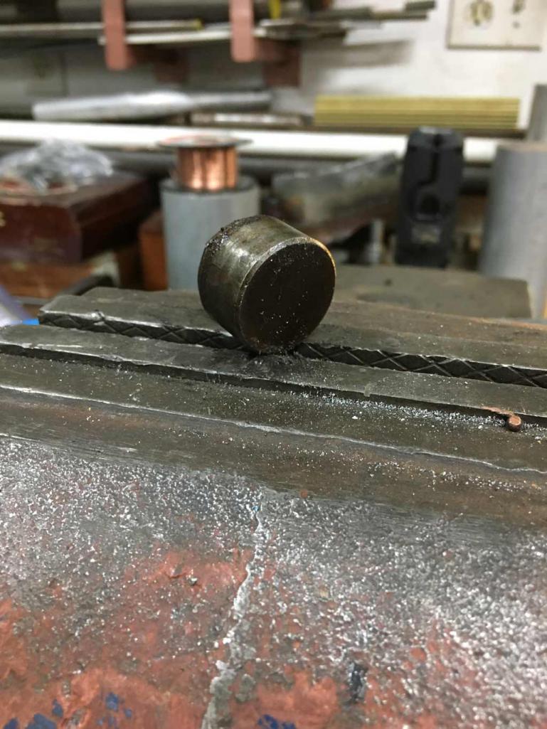
Worse than the rust debris / garbage there is some sort of round metal object in here. Luckily it was too big to ever fall into the case. 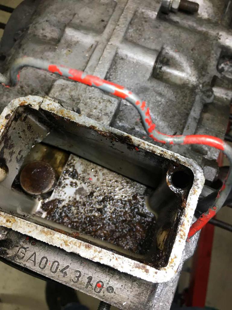
I have no idea what this is or where it came from. Any ideas? Here are two views of it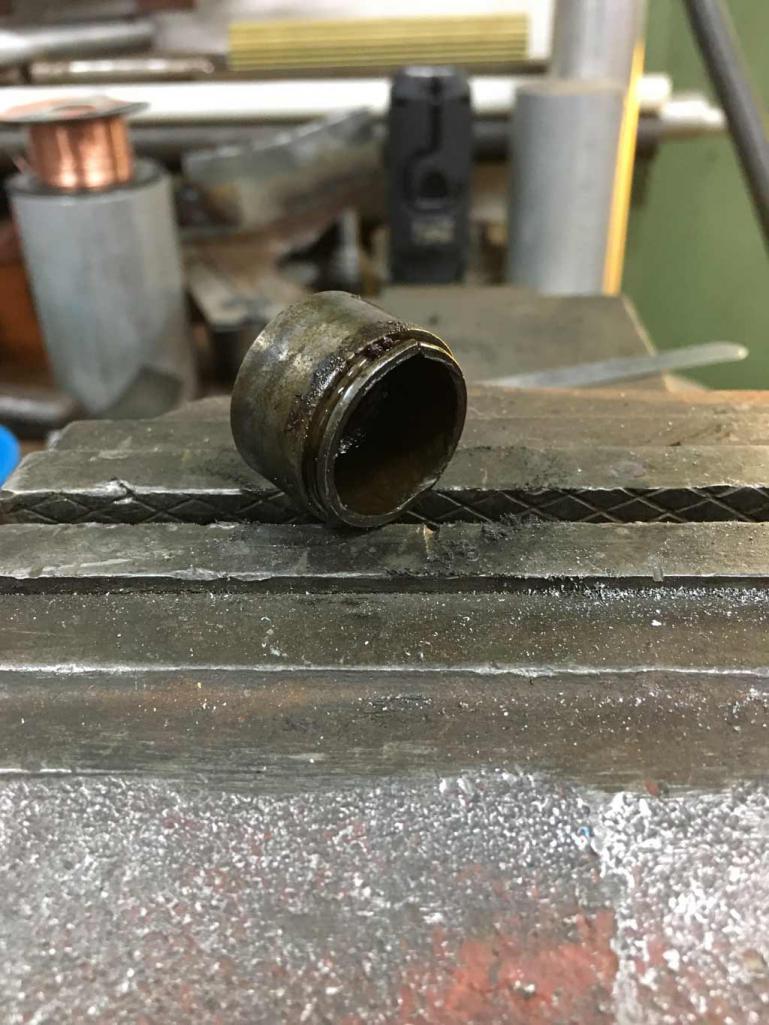
Posted by: Superhawk996 Apr 28 2019, 05:03 PM
On a more positive note. Most of the other engine components are in pretty good shape upon 1st look.
Lots of oil leaking on the case from push rod tubes, some weepage at the base of the cylinders.
Crank seals are hard as rocks and leaking profusely from getting it running and the brief neighborhood drive. Oil cooler seals were hard too and leaking.
Oil pressure sensor hole is indeed stripped and leaking and will need to be re-tapped.
Overall I'm relieved to find the cylinder heads are 2.0L parts and I think the valves may be original. IIRC the exhaust valves with the little dimple in the center are the original 2.0L sodium filled valves. I'm not sure - have to do so research on that. Regardless, all valves will get replaced at rebuild. 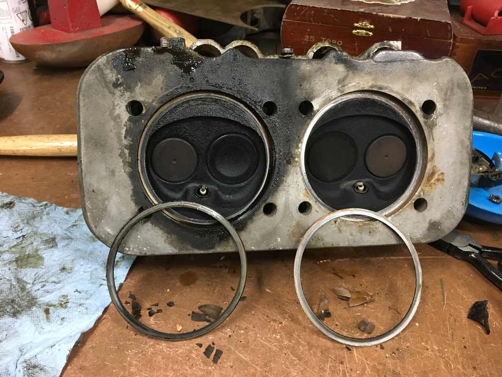
I also was happy to find the exhaust stud that I knew was missing appears to actually be a pulled timesert. The hole appears to have been drilled properly by a machine shop since it's located properly and not offset to the original stud bore. 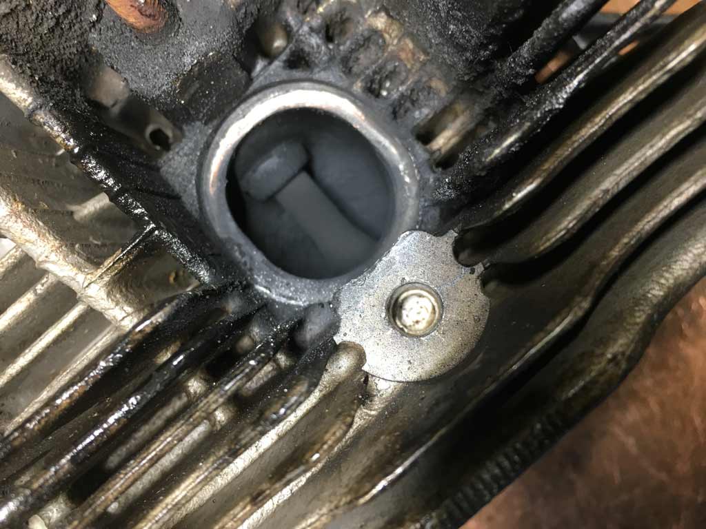
A couple of the cylinders are scored and one appear to be pretty corroded on the bottom of the bore. Probably from the long period of storage and condensation inside the cylinder forming. New pistons and cylinders planned so not a big deal. Was also happy to find the cylinders are 94mm and not some big bore conversion that machined the case or the heads. 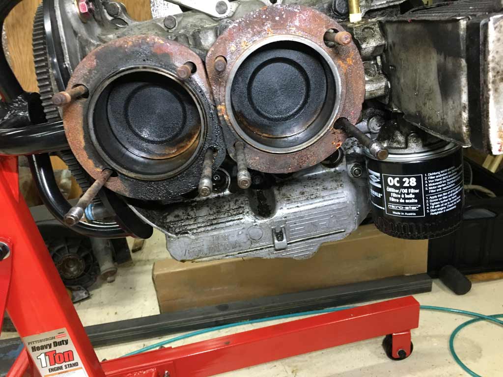
I haven't had a chance to split the case yet but after pulling the oil pump, I'm pretty sure the cam was changed based on the appearance of the cam gear. I can also see that someone covered the Cam plug and the oil galleys with epoxy or something like that. Hopefully this was a preventative measure rather than some crappy fix that I've become so accustomed to finding.
Posted by: bbrock Apr 28 2019, 05:13 PM
When I rebuilt my short block, I filled all the galley plugs with JB Weld as a preventative base on a tip I read (probably in VW Porsche Magazine) at the time. Seems like that might not be the best method but it was the best info I had available then. Maybe whoever did yours read the same article...
Posted by: Superhawk996 Apr 28 2019, 05:24 PM
I've gotta admit JB weld is pretty good at resisting oil.
I punched a hole in my Miata's sump going up a goat trail to a house out in Idaho. I didn't realize it until the lifters began to clatter and then I looked at the oil pressure and it was zero. Hmm, now what to do?
Being quite a way from town, I used JB Weld to patch up the crack. Filled it with oil, and it turned out to be a pretty robust fix. I was always afraid the JB weld would eventually let loose - that never happened.
Now in the interest of honesty . . . that is not my idea of a good fix. But the car had in excess of 220K miles on it at that point and they body was rusted away by mid-west cancer. Spending $$ to buy an new oil pan and/or for welding would have exceed the value of the car. I know . . .
Posted by: Superhawk996 Apr 28 2019, 05:27 PM
Here is the Miata in it's prime as a MUV. Miata Utility Vehicle. 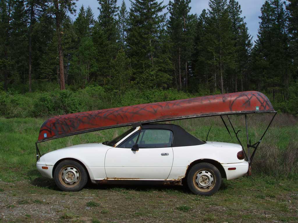
Posted by: bbrock Apr 28 2019, 05:57 PM
Here is the Miata in it's prime as a MUV. Miata Utility Vehicle.
Love it!
 It remains to be seen if I'll have the nerve to strap my canoe on my 914, but it would check off two of my most favorite things to do in one trip!
I was exploring JB Weld as a potential high temperature filler to smooth out some pits and dents on my valve covers and was surprised to see it rated up to 500 degrees. Too bad had just run out or I would have given it a go. Great stuff.
My brother lives in Sulphur Springs, TX where J-B Weld is located and has met the founder/inventor. He said the guy was sitting on a plane one day waiting for take-off and looked out to see a J-B Weld patch on the wing.

Posted by: Superhawk996 Apr 28 2019, 06:12 PM
@http://www.914world.com/bbs2/index.php?showuser=20845
Wait a few years, but, you definitely should do it, I'm biased given my penchant for strapping oversize items to sports cars.
Posted by: Superhawk996 Apr 28 2019, 06:18 PM
Here's a video of the posted Miata turning 220,000 miles.
I had a bet with a buddy that it wouldn't make 220K the way I drove it without an engine rebuild.
Video was sweet victory.
https://www.youtube.com/watch?v=6-m2IT4Xojo
Posted by: Dave_Darling Apr 28 2019, 07:02 PM
Worse than the rust debris / garbage there is some sort of round metal object in here. Luckily it was too big to ever fall into the case.
Interesting. It looks about the right diameter for the cover over the bottom of the PCV valve, but the cover is much thinner. Perhaps it was a home-made block-off for the PCV system?
The cover comes to mind because it always seems to fall off and land right in the spot you show
--DD.
Posted by: bbrock Apr 28 2019, 07:31 PM
Worse than the rust debris / garbage there is some sort of round metal object in here. Luckily it was too big to ever fall into the case.
Interesting. It looks about the right diameter for the cover over the bottom of the PCV valve, but the cover is much thinner. Perhaps it was a home-made block-off for the PCV system?
The cover comes to mind because it always seems to fall off and land right in the spot you show
--DD.
That was my first thought as well but I just took mine apart to clean and repaint a week ago and the cover was plastic.
Posted by: bbrock Apr 28 2019, 07:36 PM
Here's a video of the posted Miata turning 220,000 miles.
I had a bet with a buddy that it wouldn't make 220K the way I drove it without an engine rebuild.
Video was sweet victory.
https://youtu.be/6-m2IT4Xojo
Badass!
We'll just assume you weren't on a public road. ![whistle[1].gif](style_emoticons/default/whistle[1].gif)
Posted by: Tenner Apr 29 2019, 02:55 AM
A few posts earlier, you've been talked about the repairpanel of the inner frame section and it bothers you that it's not made like the original which is two layers of steel ...
This bothered me too and I decided to build my own repaipanel. The Panel will be a combination off an own build outer layer and the Restorationdesign repiarpanel as the inner reinforcement layer. This is what I've built so far.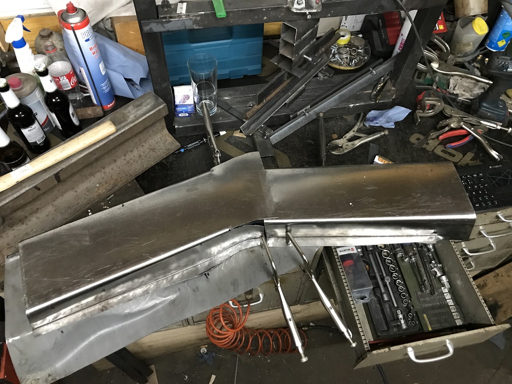
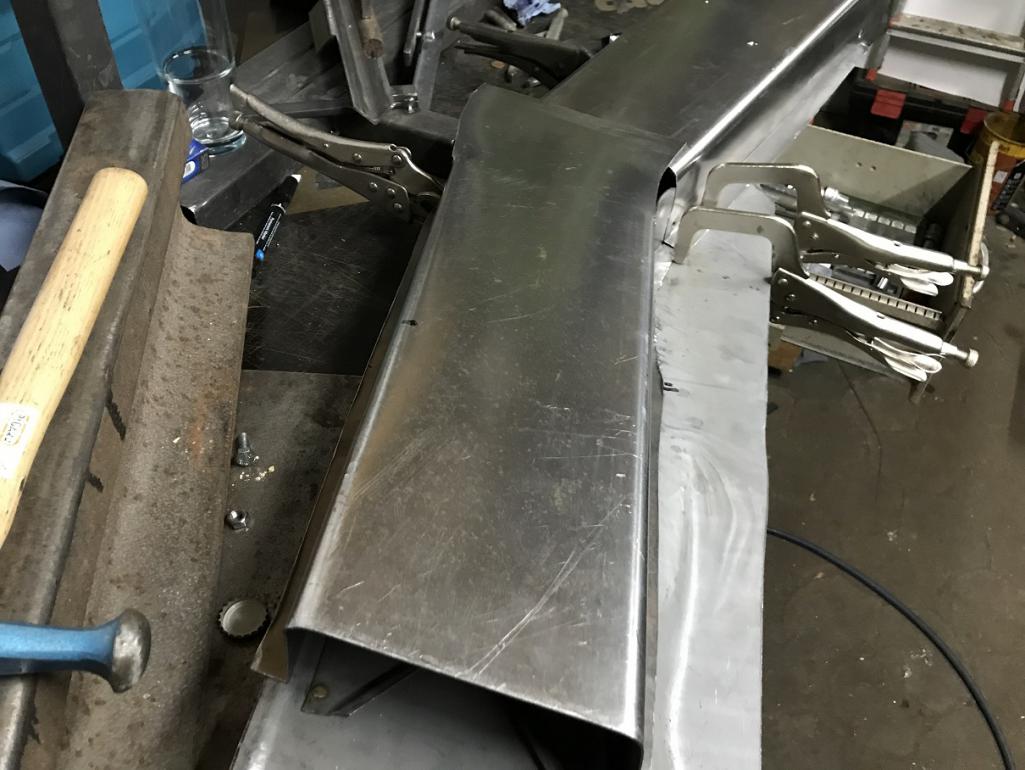
The panel is made from one piece of 1.2mm sheetmetal and fits nearly perfect to the inner wheelhouse repiarpanel. It took me about half a year and 4 tries to make it right. I ended up making my own tools to get the edges properly bended.
Next step is trim the overlap, fill the gaps, fit the inner layer and finaly fit it to the car before welding it in.
If anyone is interested in the building process, I will open a new thread to discribe the process
Posted by: injunmort Apr 29 2019, 04:33 AM
to fill pits in rocker covers, try boiler cement. I have used for similar purposes. dries rock hard (hard to sand) but stands up well to the environment. good enough to seal boiler fireboxes good enough for some light cosmetics. way cheaper than jb weld.
Posted by: Superhawk996 Apr 29 2019, 04:44 AM
@http://www.914world.com/bbs2/index.php?showuser=11863
Looks like nice work. You most definitely should open a thread. That is the biggest advantage of the site, the shared knowledge base and the ability to learn from others.
I probably would have never purchased this car and/or started this level of rehab without having seen some of the other build threads particularly Jeff Hail's and Brent's.
@http://www.914world.com/bbs2/index.php?showuser=1570 Hail
@http://www.914world.com/bbs2/index.php?showuser=20845
Both of those vehicles were just like mine - candidate for scrap. Without seeing that it could be done and more importantly, that it was worth doing, I would have never gotten started. At least here in the mid-west, good solid 914's are getting harder to find. When you do find them, they are priced such that at those price levels ($15k-25k) I'd be back to considering another Miata or a Lotus Elise with modern build quality vs. a 45 year old car that I know is going to have issues anyway.
Posted by: restore2seater Apr 29 2019, 08:04 AM
I have no idea what this is or where it came from. Any ideas? Here are two views of it
Not sure the size in the picture, but it looks kind of like one of the four ends of a ujoint off of a drive shaft.
Posted by: bbrock Apr 29 2019, 08:11 AM
@http://www.914world.com/bbs2/index.php?showuser=11863
Looks like nice work. You most definitely should open a thread. That is the biggest advantage of the site, the shared knowledge base and the ability to learn from others.
@http://www.914world.com/bbs2/index.php?showuser=11863 +1 on opening a thread. I also made my own double wall patch for that inner but not as nice or complete as yours. It is a PITA job so I think sharing your approach would help a lot of people!
Posted by: injunmort Apr 29 2019, 10:18 AM
brake piston
Posted by: Superhawk996 Apr 29 2019, 11:40 AM
brake piston
Good guess . . . but it would have to be off a Smart Car.
 Hard to see scale from the photo but it is 1" diameter and about 0.75" in height. Made of steel.
 Maybe from Motorcycle caliper . . . . ?
I have a feeling this is going to be one of those mysteries that I just end up chalking up to "what were they thinking".
Even if it were a home brew PVC block off, that doesn't even seem to fit in my engine's history since they had a EMPI type breather box hooked up to one of the heads and the other off the oil fill / breather box. Both of those lines were then fed into the top of one of the carbs.
Posted by: jd74914 Apr 29 2019, 12:08 PM
For you other TiG lovers, I have to plug this product. It is a pressure sensitive Amptrol. No need to move finger to control amperage - just press harder or lighter.
http://www.6061.com/tigbutton.htm
Wow, that is cool. Thanks for the info! I hate the finger slide or rotary track so much I've always either resorted for scratch start and constant current or ended up in weird positions working the pedal with my knee, elbow, thighs...
Kinda pricey piece though.
Posted by: Superhawk996 Apr 29 2019, 01:49 PM
For you other TiG lovers, I have to plug this product. It is a pressure sensitive Amptrol. No need to move finger to control amperage - just press harder or lighter.
http://www.6061.com/tigbutton.htm
Wow, that is cool. Thanks for the info! I hate the finger slide or rotary track so much I've always either resorted for scratch start and constant current or ended up in weird positions working the pedal with my knee, elbow, thighs...
Kinda pricey piece though.Not so bad if you consider that it is only about 10% of cost to get into a TIG rig to start. Then there is the sanity element. I tried the Yoga thing and quite honestly, I had a hard time controlling it while welding on 1/8" tube. There was no way I could pull off the out of position welds on sheet metal without it.
Owner of the TIG button is a real down to earth guy. The site didn't specifically have my Precision TIG unit listed as compatible. He offered to let me try it risk free. Worked great right out of the box. After trying it there was no way it was going to be returned. I don't even use my foot pedal anymore . . . even if I'm welding on the bench. It's that natural.
Posted by: Superhawk996 May 5 2019, 08:44 AM
So I got around to splitting the case and the results aren't good. Did I mention I really dislike the way the previous owners treated this vehicle? 
The source of the rust that was in the top of the oil filler has been found. I quickly put the oil filler & breather box aside when I was doing the initial teardown. I could see had some rust & oily gunk in there but I didn't dwell on it. 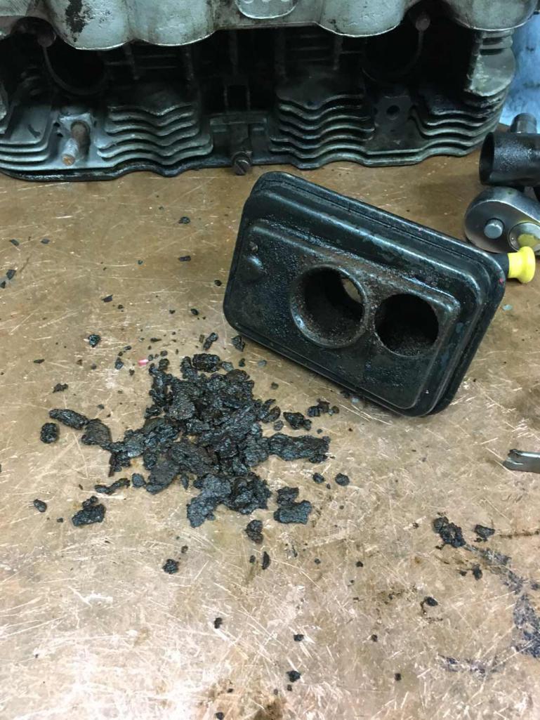
If someone has one of these they would care to sell, there will be an ad going up in the classified section to replace this one. PM me if you have an extra you want to get rid of!
What I can't believe is how much more rusty garbage is down in the sump.
There is a staggering amount of rust and crap sitting on both sides of the case. 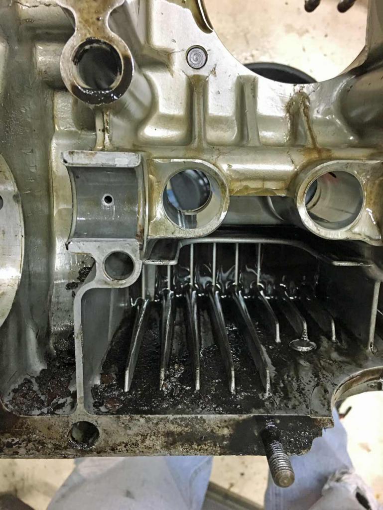 \
\
I find it a little bit hard to believe that all of this came out of the breather box.
There are other indications that this engine was not rebuilt properly.
I found a metal shaving behind one of the cam bearings. luckily there was no way for this to get though the bearing oiling hole. But it does speak to the fact that the oil galleys probably were not cleaned properly before the rebuild. 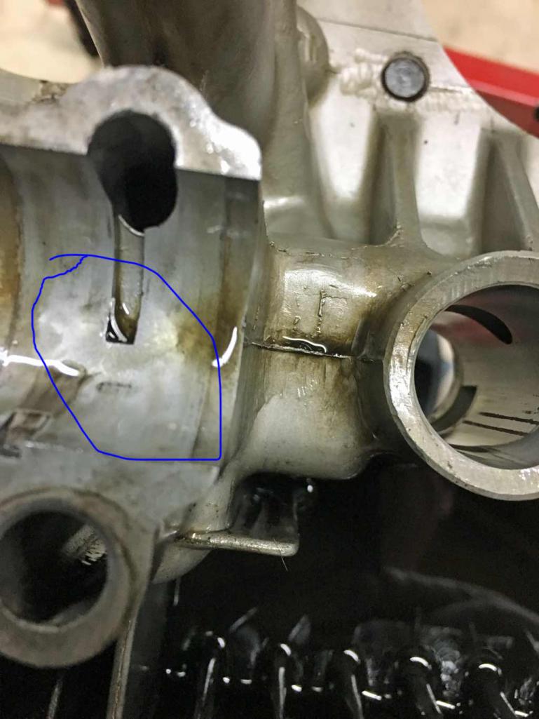
Of course the bearings are worn from all this garbage in the oil and the crank is lightly scored. Hopefully the crank can be cleaned up with either an aggressive polishing and/or maybe a 1st size under cut. I need to measure the journals today to see where they are at. 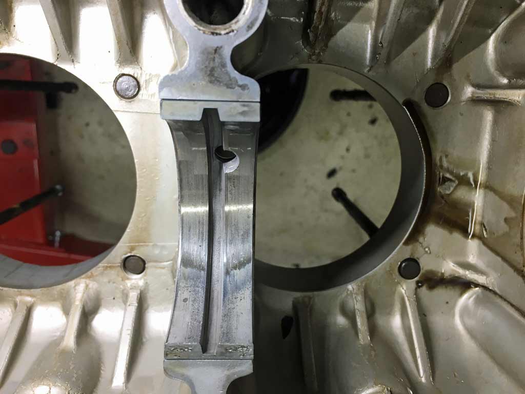
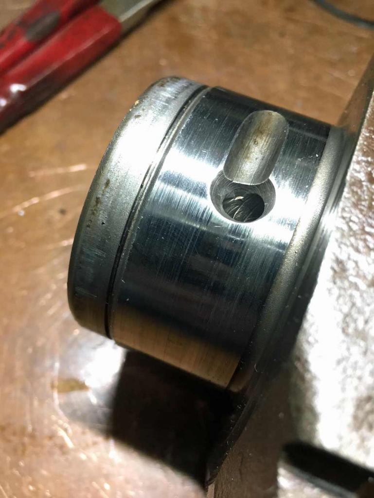
And now let's move on to the truly egregious and incompetent stuff.
Front crank seal bore has witness marks in it from someone threading a fastener into it. Maybe they had no idea how to pull a crank seal? 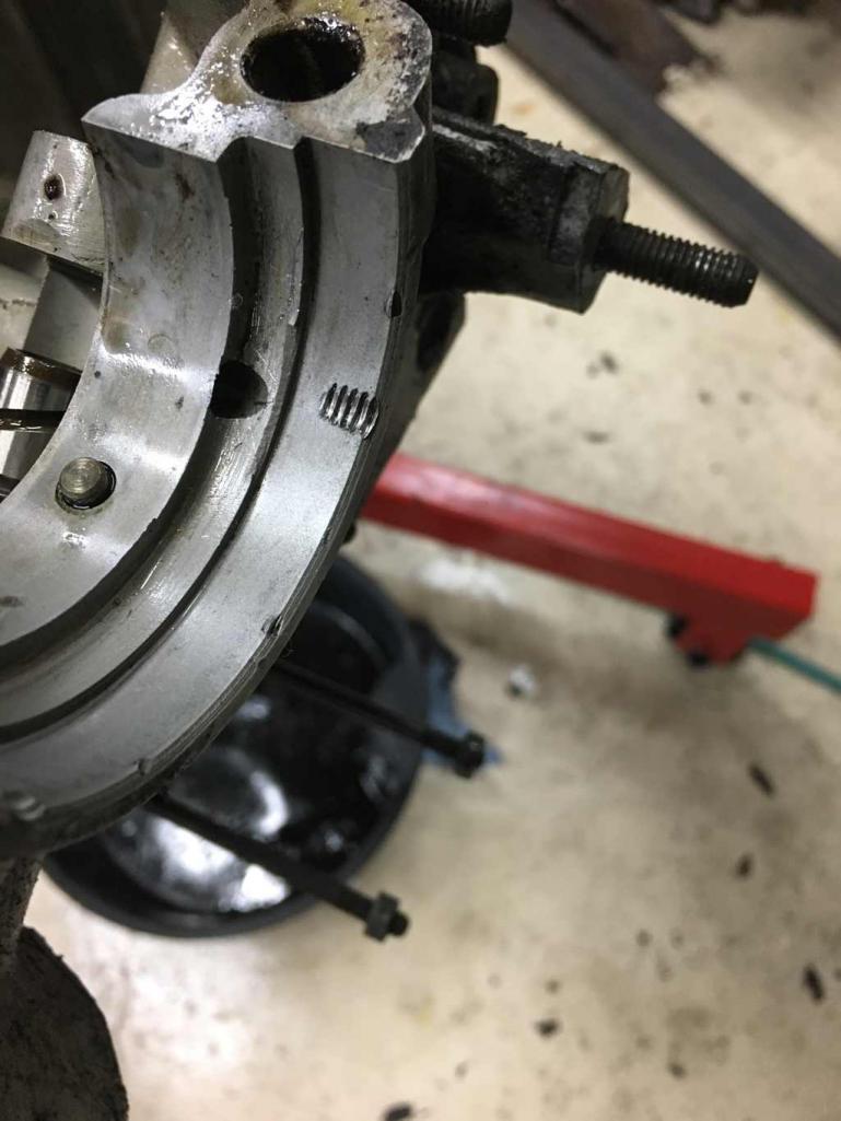
This case was literally covered in oil. It also tended to leak oil even when it wasn't running. As it sat on a dolly in my garage all winter, I kept wiping up weeping oil from under it. Eventually, I put a carboard box under it to catch the oil.
Now I know why. As far as I can tell there was little, if any sealant between the case halves!
Now keep in mind, someone plastered up the back side of the case with Epoxy / JB Weld type material over the cam plug and the oil galley plugs. After this find, I suspect they were trying to stop the oil leak that was actually coming from between the case halves from not having proper sealant on them.
There were also a number of other hits that the rebuilt was done on the cheap.
1) There were no vibration dampers on the six main bearing through bolts and/or any sealant under the washer heads to help bolt vibration and to help prevent leaks and weeping from these main case bolts. I'm always amused when a shade tree mechanic throws away parts. Surely they weren't serving any purpose and those stupid Germans were just putting extra parts in.
2) Numerous gaskets that looked like they were reused.
3) Lots of screwdriver marks on sealing surfaces where somebody was prying surfaces apart that shouldn't be touched by tools.
None of this appears to be un-fixable but it speaks to the horrors that you can find in an amateur engine rebuild by someone that clearly is just learning.
Posted by: bbrock May 5 2019, 10:10 AM
Gross! The curse of a great "beginner's engine." I should have you covered on an oil breather. I need to open it up to make sure there are no surprises inside. Should be clean though. I'll PM you later.
Posted by: Superhawk996 May 5 2019, 10:37 AM
By the way,
This engine had at least enough oil pressure to turn off the idiot light. So no guarantee that a used running engine with oil pressure means that the engine is in OK shape.
Brent, if you have a breather that would be stellar!
Posted by: Superhawk996 May 5 2019, 05:47 PM
Can’t catch a break. Both rod and main bearings are 0.010” undersized! Going to be looking for a new crank
Posted by: bbrock May 5 2019, 07:43 PM
Brent, if you have a breather that would be stellar!
I was hoping to have better news for you. Looks like this breather would clean up okay, but it's missing the cover for the PCV. It's yours if you want it, but you know me, I'd want one with all the right bits. I'll try to get out to the storage shed tomorrow. There is a small chance there is another breather of two hiding out there.
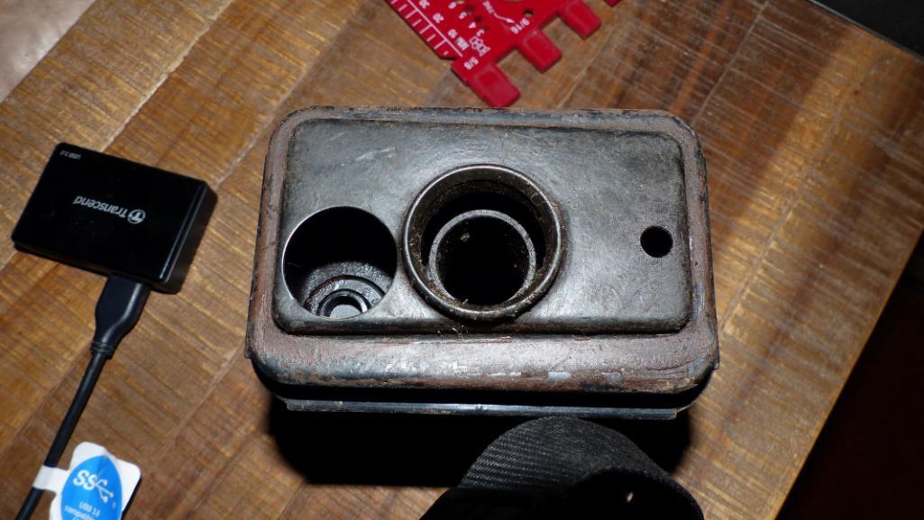
Posted by: Superhawk996 May 6 2019, 04:34 PM
Brent, if you have a breather that would be stellar!
I was hoping to have better news for you. Looks like this breather would clean up okay, but it's missing the cover for the PCV. It's yours if you want it, but you know me, I'd want one with all the right bits. I'll try to get out to the storage shed tomorrow. There is a small chance there is another breather of two hiding out there.
That’s funny because mine doesn’t have a cover either and I can’t find a picture of it nor can I recall from my original car what it looked like.
Posted by: bbrock May 6 2019, 05:56 PM
I assume this is to prevent oil from splashing into the PCV and gumming the valve. You could probably find a plastic button to snap in and slit the sides to let it breath.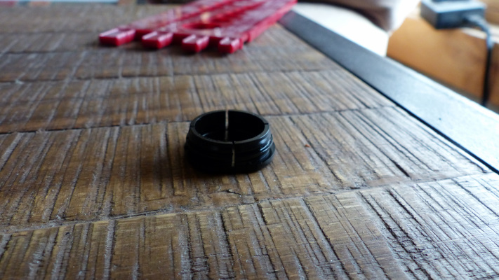
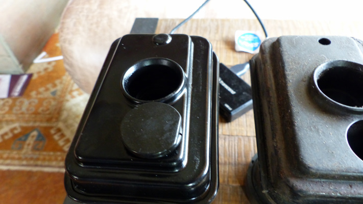
Posted by: Superhawk996 May 6 2019, 06:28 PM
I hate to even ask. What's the 3rd hole for? Maybe slightly different for 1.7L/1.8L?
Given the appearance of the button that would be pretty easy to fabricate out of Delron of something like that.
I just looked of AA and of course the cover button is NLA. I'll have to do some digging I wonder if 914 Rubber has it.
Definitely needs to be some sort of soft plastic given potential for it to drop into the case. Yikes!
Posted by: bbrock May 6 2019, 09:17 PM
Ha! Never noticed the third hole before. The breather on the right came out of a 1.7L. Don't know if that makes a differences though.
The hole under the PCV is just shy of 1 inch and I'll bet a 1 inch plastic hole plug would fit. Should be able to pick one up at the local auto parts store. Let me know if you want me to pop my extra one in the mail.
Posted by: bbrock May 6 2019, 09:18 PM
BTW, might not be clear in the pics, but the third hole on the breather is not a hole, just an indent stamp in the metal.
Posted by: FourBlades May 7 2019, 07:40 AM
Great job on the build!
Really enjoying the thread so far.
Once you get to drive it, it will all be worthwhile.
Mine needed a little work when I got it, can you say flintstone car?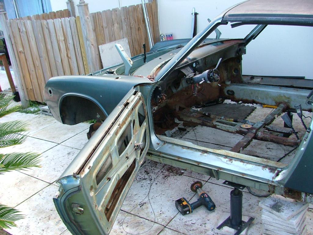
But it all worked out eventually.
John
Posted by: Superhawk996 May 7 2019, 08:01 AM
Great job on the build!
Really enjoying the thread so far.
Once you get to drive it, it will all be worthwhile.
Mine needed a little work when I got it, can you say flintstone car?
But it all worked out eventually.
John
Inspiration!
So nice to see others that have come back from the brink. I'm right in the middle which is the land of desperation where you start thinking why did I do this?
Only one way to go. Soldier on and finish it.
Posted by: FourBlades May 7 2019, 09:39 AM
I find it helps not to:
(1) Add up how much longer it will take to be on the road.
(2) How much it has cost so far.
(3) How much more it will cost to finish.
Just tackle the project you have selected for the day and enjoy the satisfaction of crossing another thing off.
John
Posted by: Superhawk996 May 16 2019, 06:01 PM
My stitches are all healed up and I'm looking forward to getting back to doing to what we do around here. 
I've been collecting up parts to put my engine back to stock 2.0L form with 94mm pistons and a stock crank and hopefully getting D-jet back on it instead of the carbs that it came with.
I know . . . . . the horror of it . . . . stock! 
Today the mailman was really pissed. Pistons and Cylinders arrived and I think he might have broken a sweat carrying them up to the door. In his defense, they are heavier than a letter. More likely he's mad that he has to keep getting out of the truck with all the regular parts arrivals.
So happy to have found NOS P&C's with proper dish. You can see the PO simply put VW BUS deep dish pistons in on the last rebuild. 914 compression ratio is pretty low by modern standards. Those deep dish would have lowered it even further. I'm sure they were cheap though!
@http://www.914world.com/bbs2/index.php?showuser=20991
Thanks for facilitating this transaction! 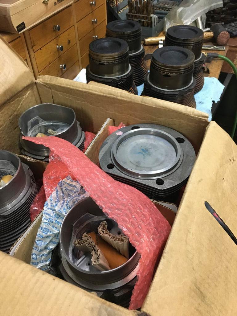
Fed Ex man isn't doing much better because my "new" crank showed up today too! The crank that came out of my engine had already been ground 0.010" on both the journals and the mains so why take a chance with that one. This new one will go to machining for a very light polish and a quick magnaflux check. Initial measurement of the mains and journals shows it to be on the high side of stock tolerance which is AWESOME!
@http://www.914world.com/bbs2/index.php?showuser=18761
Thanks for providing a heat transplant for this engine. 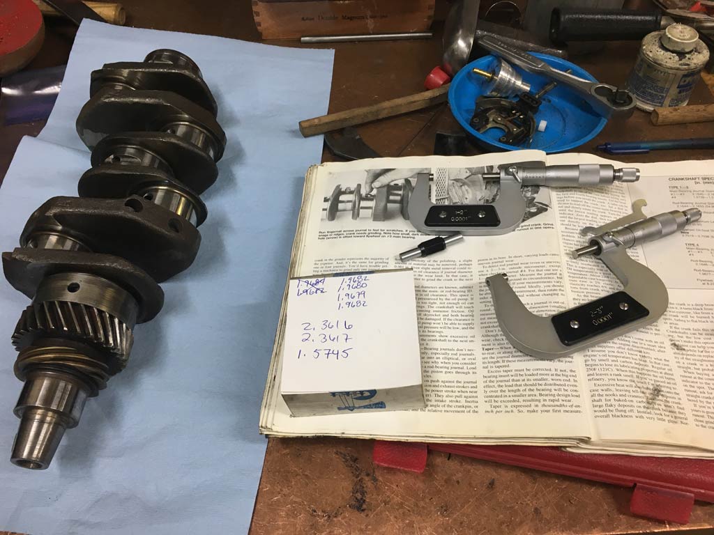
I've also picked up some stainless heat exchangers that will clean up nicely and have now been pressure tested to make sure there are no leaks in the actual heat changer that provides cabin air.
@http://www.914world.com/bbs2/index.php?showuser=17736
Thanks for making this an easy transaction! 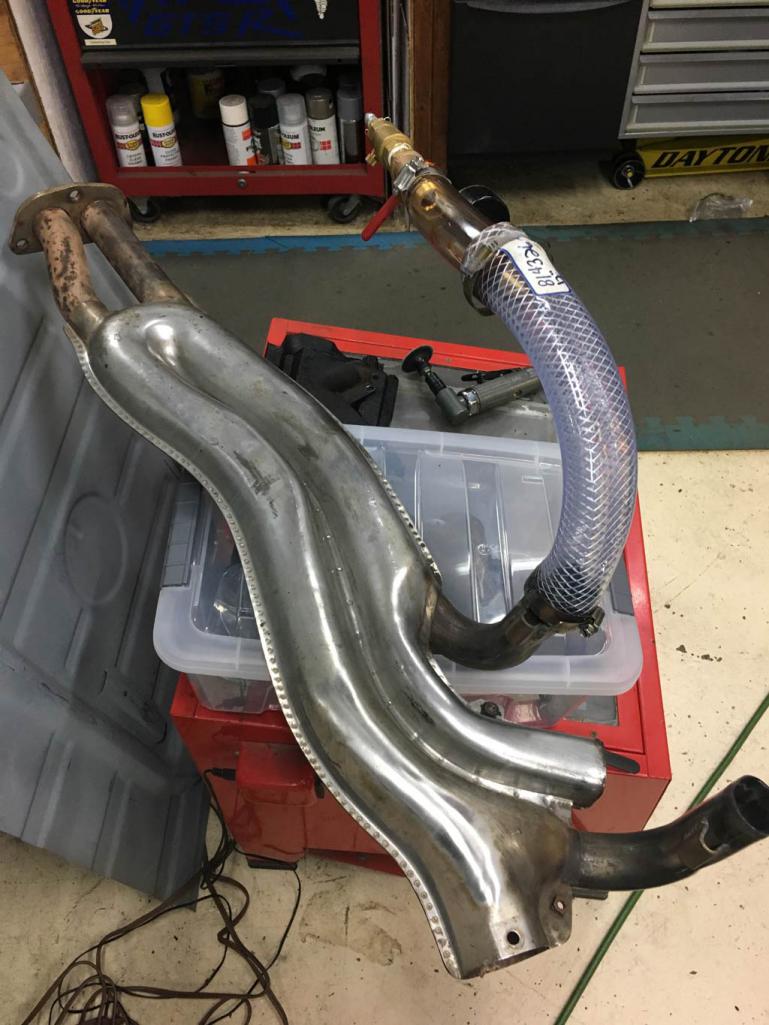
@http://www.914world.com/bbs2/index.php?showuser=3457
I'm sorry that you're cleaning out your private stash . . . . well maybe not!
Pedal sled has been rebuilt. I honestly can't even recall who I got the donor from . . . regardless thanks! My original base sled is too heavily rusted to even think about using. This one cleaned up nicely! 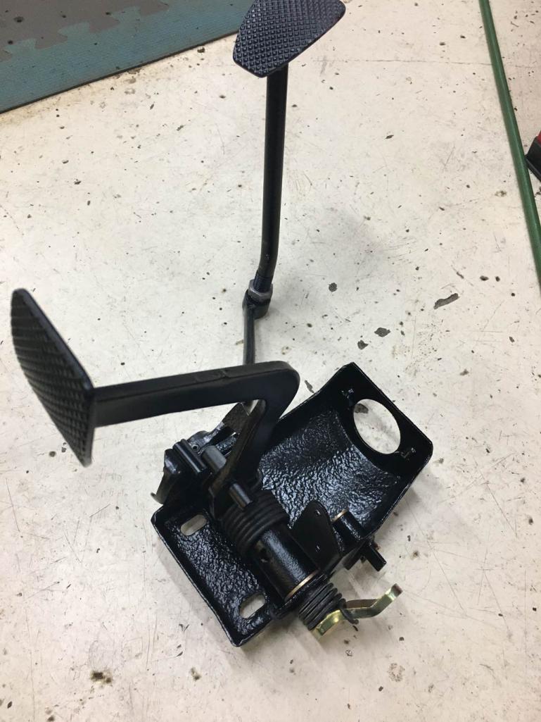
So many others have provided parts that would otherwise be an absolute pain in the  to source off Evil Bay.
I've left off so many others that have sold me parts either recently or in the past months only because I can't immediately recall your user names to provide a shout out. I've not had a single bad transaction which is a huge advantage of this community. I honestly can't imagine how I'd pull this rebuild off without 914World.com
For those that might be on the fence, go ahead and make a donation to this site. Let's keep this afloat and thank SirAndy for doing this!
@http://www.914world.com/bbs2/index.php?showuser=179
Thanks to all of you guys!!
Posted by: bbrock May 16 2019, 07:18 PM
Great progress! Anyone know what the CR on those bus jugs were? Man that's gotta be low. Jeffrey is the man for brokering NOS deals. I need to post up what he did for me when I update my thread.
Keep the postman angry. Stock rocks!
Posted by: Superhawk996 May 16 2019, 07:32 PM
Great progress! Anyone know what the CR on those bus jugs were? Man that's gotta be low. Jeffrey is the man for brokering NOS deals. I need to post up what he did for me when I update my thread.
Keep the postman angry. Stock rocks!
Special thanks to both Brent and Kevin for donating free parts, you guys are awesome. I’m sure I’ll have a few extras floating around after I get this back on the road. I will be sure to pay it forward as you guys have kindly done for me. Cheers
Posted by: 914_7T3 May 17 2019, 06:54 PM
I've been collecting up parts to put my engine back to stock 2.0L form with 94mm pistons and a stock crank and hopefully getting D-jet back on it instead of the carbs that it came with.
I know . . . . . the horror of it . . . . stock!
Today the mailman was really pissed. Pistons and Cylinders arrived and I think he might have broken a sweat carrying them up to the door. In his defense, they are heavier than a letter. More likely he's mad that he has to keep getting out of the truck with all the regular parts arrivals.
So happy to have found NOS P&C's with proper dish. You can see the PO simply put VW BUS deep dish pistons in on the last rebuild. 914 compression ratio is pretty low by modern standards. Those deep dish would have lowered it even further.
I'm sure they were cheap though! @http://www.914world.com/bbs2/index.php?showuser=20991
Thanks for facilitating this transaction!
My pleasure, we stock '73 2.0 guys need to stick together. Even if @http://www.914world.com/bbs2/index.php?showuser=20845 is running a Carb set-up
I will take some time to catch up on your thread!
Posted by: Superhawk996 May 19 2019, 09:36 AM
I did a little more "clean" work yesterday to take a look at my oil pump and sifting though FI parts.
As expected, oil pump is toast. With all that rust in the sump, it clearly has been pumping chunks! Now the real problem starts - trying to find a replacement oil pump.
Unlike when I built my last motor, type 4 pumps are now in short supply. I've reviewed a bunch of the threads on this site, and, I don't really like the options around using a type 1 pump.
Here's the trashed pump. The two issues are heavy scoring of the pump body and the pushing out of the stationary shaft that occurs as a result to having been overheated at some point (remember some damn previous owner pulled thermostat and cooling flaps )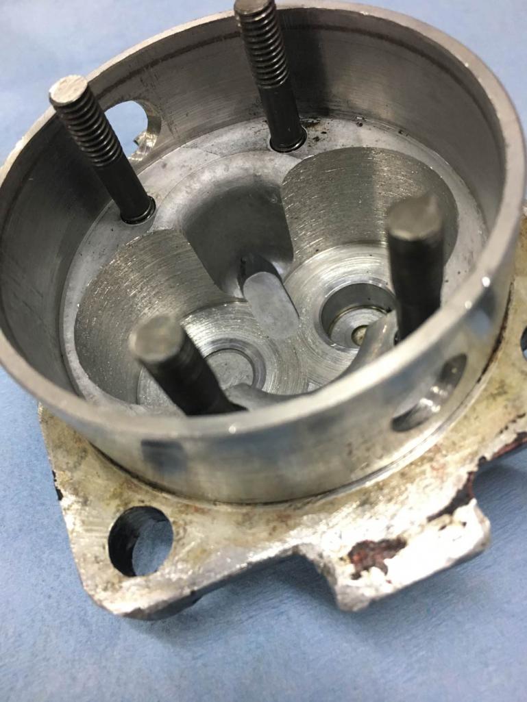
The camshaft I took out of the engine does show witness marks from the shaft contacting the cam gear bolt heads. 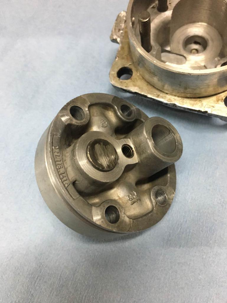
This situation has me thinking about ways to rebuild a Type 4 pump. I'm sure it can be done but the problem is time and effort to do so. I'm sort of surprised no one has come up with a CNC aftermarket replacement since there are still a lot of Type 4's running around in 914's and VW busses.
I've resorted to rolling the Evil Bay dice. I bought a pump that looks great on the outside - but it very well could be money down the drain once I open it up.
If it were able to be used, I'll certainly modify it to pin the stationary shaft in place so that well known failure mode can't occur. In reality, I reused my oil pump when I rebuilt my original 73' 1.7L to a 2.0L and that pump went about 100K miles before that vehicle was totaled by a rear-ender. When I tore the engine back down, that oil pump was still solid. Wish I had kept it but it was sold at Hersey decades ago.
We'll see where this eBay path leads.
I've also been picking my way though D-Jet parts trying to ensure I have usable components. The injector points need a bit of help. I'll fix these with a bit of new copper braid and some solder.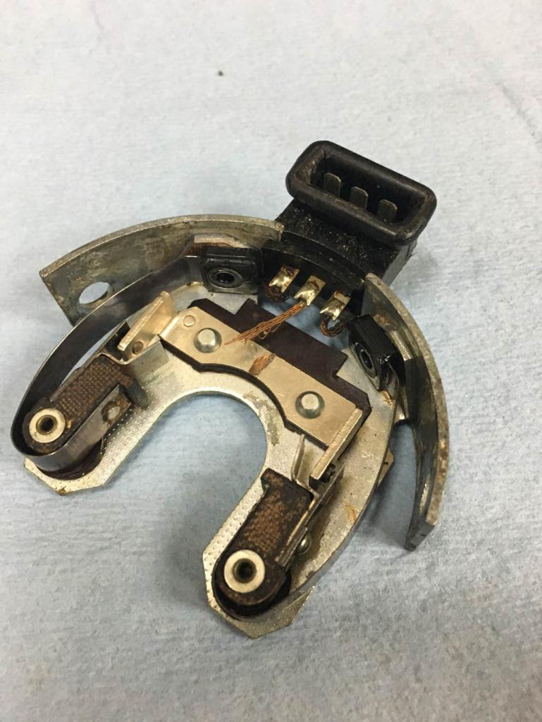
Posted by: 914_7T3 May 19 2019, 10:41 AM
I did a little more "clean" work yesterday to take a look at my oil pump and sifting though FI parts.
The camshaft I took out of the engine does show witness marks from the shaft contacting the cam gear bolt heads.
I've also been picking my way though D-Jet parts trying to ensure I have usable components. The injector points need a bit of help. I'll fix these with a bit of new copper braid and some solder.
Why didn't you say so, I have an extra trigger plate that is lightly used. Picked it up as a spare, but then found a NOS one

Let me know if you want it and I can email you pics and we can work something out.
Posted by: Superhawk996 May 19 2019, 11:14 AM
Why didn't you say so, I have an extra trigger plate that is lightly used. Picked it up as a spare, but then found a NOS one
Let me know if you want it and I can email you pics and we can work something out.
@http://www.914world.com/bbs2/index.php?showuser=20991 You're the best. If I wrote down a list of everything I "need" you'd have to send me your car!
Points already fixed.
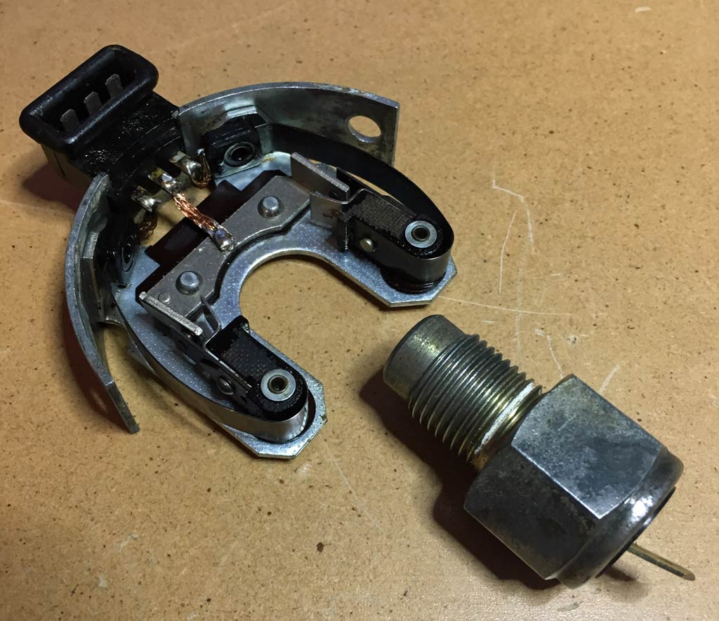
If only everything were that simple.
I will be looking for an Ambient Temp Sensor (in photo) and posting it at some point on WTB classifieds. Just in case you happen to have one sitting around.
Posted by: Superhawk996 Jun 4 2019, 06:40 PM
Finally got a call from the machine shop that was cleaning my case and seeing if they could polish out the crank that was already 0.010" undersize.
The case turned out nice but will still need lots of love. This engine had massive rust in the sump. All galley plugs will need to be pulled so that the ends of the galleys can be cleaned to ensure there isn't a nice little pile of rust at the dead end just waiting to come out inside a freshly rebuilt engine.
There will also be machine work to deck the piston seats lightly, and the oil pressure sensor hole is stripped and will need to be re-tapped. 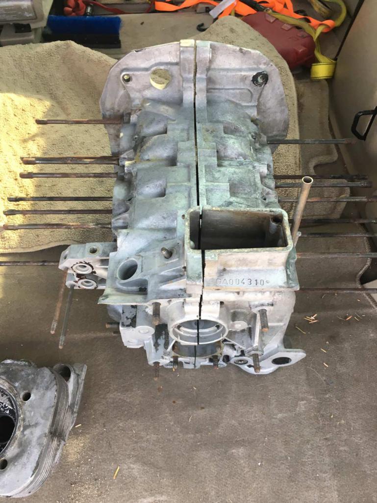
Now for the bad news. One cylinder is cracked at the boss for the valve guide. Likely a result of prior poor workmanship. I can see evidence of the valve guide having been replaced previously.
I'm undecided on next steps for this head. I hate to toss a 2.0L head. May weld it but that will be down the road since it will involve lots of work to weld it and then to re-machine the valve guide boss properly. I will probably bead blast it just to see if there are other cracks in the combustion chamber to help seal the deal. 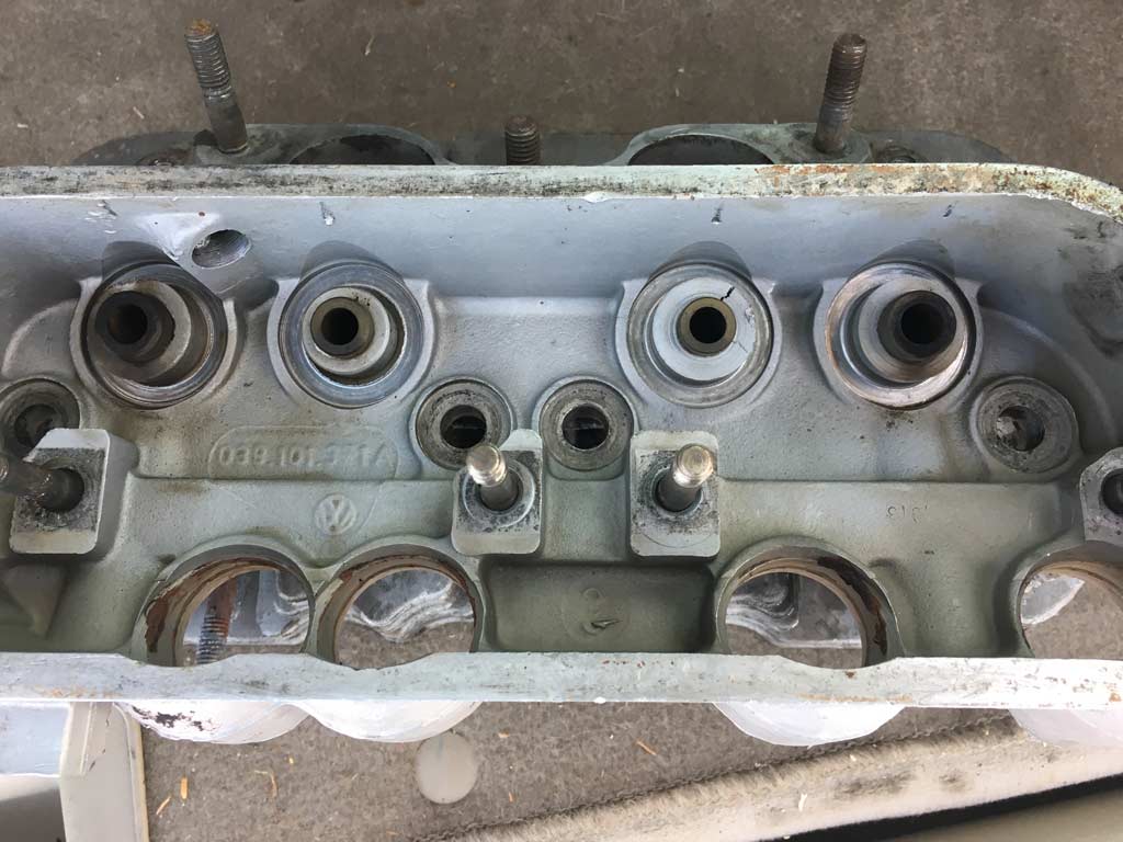
Ah . . . the joy of restoring 40+ year old cars.
Posted by: Superhawk996 Jun 4 2019, 06:46 PM
The crank actually did polish out pretty well but I need to measure it for myself to see where it is at. However, there is a bit of rust pitting just below where the Cam gear sits. This surface doesn't get bearing wear but it is a defect that I couldn't see with the cam gear in place.
I ended up getting another used standard size crank that is in good condition from Kevin W that will go into this engine.
If anyone is in desperate need of a 2.0L crank 0.010" under on both the mains and the rods. I will send this one to you for the cost of shipping (~$45) based on what I paid to get mine from Kevin.
Otherwise, it is probably headed toward becoming a lamp, a door stop, or something like that.
Posted by: bbrock Jun 4 2019, 06:54 PM
Finally got a call from the machine shop that was cleaning my case and seeing if they could polish out the crank that was already 0.010" undersize.
The case turned out nice but will still need lots of love. This engine had massive rust in the sump. All galley plugs will need to be pulled so that the ends of the galleys can be cleaned to ensure there isn't a nice little pile of rust at the dead end just waiting to come out inside a freshly rebuilt engine.
Is the plan to put the guts of the engine you just picked up into this case? Is this one numbers matching? Just curious.
Posted by: Superhawk996 Jun 4 2019, 07:12 PM
Is the plan to put the guts of the engine you just picked up into this case? Is this one numbers matching? Just curious.
That is a question I pondered for 14 hours while driving to/from Wisconsin.
I started this project with the mindset of saving a scrap car and not feeling bad that I'd eventually like to put a six into it after running the stock 2.0 Type 4 for a year or two.
To answer the question would take a COA. I don't feel good about sending those fools money given other members experiences with them.
Likely out come will be I'll cherry pick the best parts from each (both are 73' engines) and build one prime engine for me.
The other engine (if truly low miles) may just get pistons cleaned, cylinders honed, and put back together with fresh bearings etc. as a basic runner for sale later set up with my Dell's to someone in need? That is a very optimistic scenario.
Worst case, I'll part out what's left.
Posted by: Superhawk996 Jun 4 2019, 07:16 PM
Also as a point of note, KevinW donated a 017 CHT sensor to me before I bought engine GA000099.
I intend to fully document the resistance vs. temp behavior of both sensors for a sample size of two. I'll post the results since 017 CHT sensors seem to be a mystery. May be a bit before I get to this.
I have a few irons in the fire.
When done, I'll pay it forward by donating the extra sensor for cost of shipping to next user in need like Kevin did for me not knowing I'd end up buying another complete motor.
Posted by: Superhawk996 Jun 9 2019, 11:29 AM
Tool Of The Day Post.
I've been working to get my original case ready for some machine work.
Needed to pull the cylinder head studs.
I love these stud installers & extractors from Snap-On.
I know this can be done by jamming nuts together and hoping for the best. I did that for a lot of years when I was broke.
These collet type extractors make the job a pleasure rather than a pain. No risk of galling threads. Work the first time, every time. 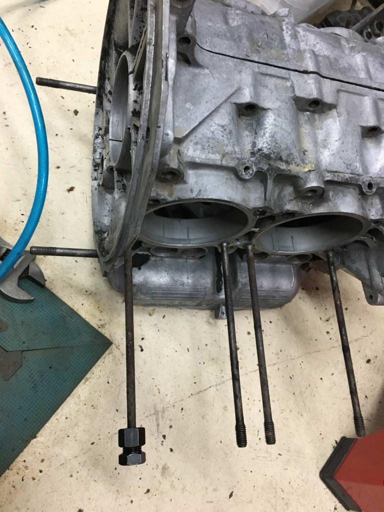
Posted by: Superhawk996 Aug 28 2019, 06:27 PM
Well it's been a while since I posted to this thread. Chassis work is on hold due to the Melanoma surgery stuff, but I'm still plugging away at the small stuff I can do without stressing my shoulder.
The engine that came out of this vehicle is GA004310. Whoever had this engine had a knack for screwing things up.
The flaps were removed from this car and the engine tin is sort of mangled on the passenger side tin at the corner where the flap rod passes through.
In anticipation of having tin sent out for media blast and power coat, I've been fixing tin cracks, stuck cheese head screws, and trying to straighten this tin back to original shape. Luckily I have decent tin from GA000099 to see what it should look like.
It's actually so bad, I'm sort of wondering if it was just a bad stamping. Otherwise, someone really worked to screw it up.
Here is the starting point. 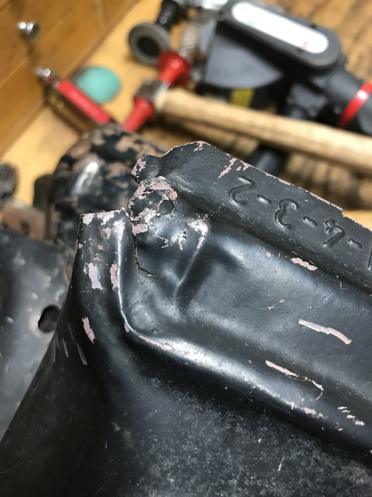
Just basic hammer and dolly work but the tight radius and the raised semi-circular formations are making it a tough slog. The photo below is getting closer but still needs a crack welded and some more shaping. 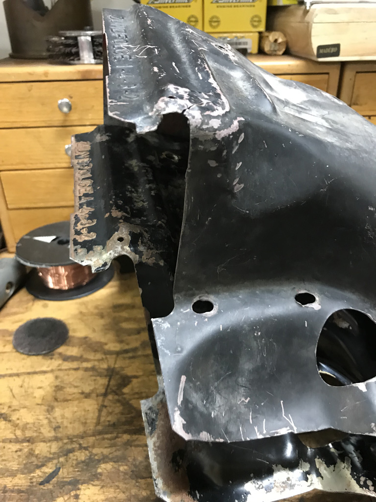
Getting a little closer to the right shape but I think a few of these creases are going to get locked in as the material work hardens. 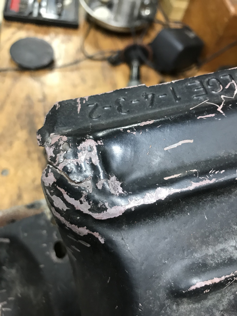
It also appears that the rear tin had two extra holes drilled for some reason. Will need to fill these. 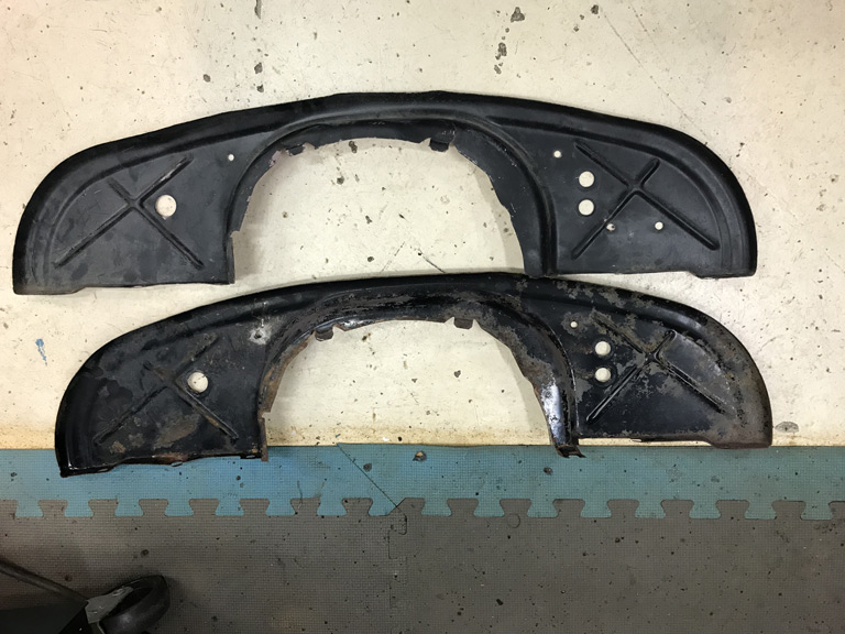
Now in the process of comparing tin between the two engines I noticed the tin from GA000099 had the 621 and I.0. markings that Brent has so carefully reproduced.
However, I did note that the I.O. mark is in a different location. Hopefully this doesn't mean he has to start all over again. 
@http://www.914world.com/bbs2/index.php?showuser=20845 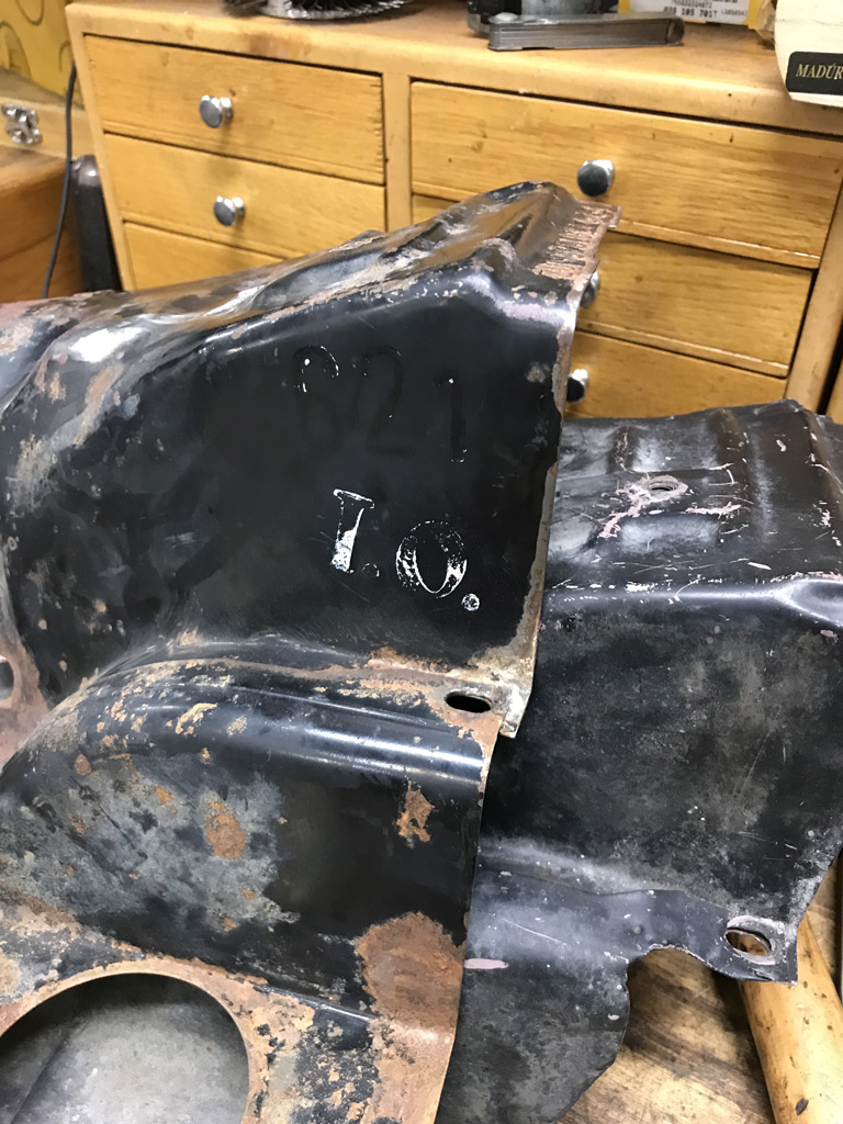
Posted by: bbrock Aug 28 2019, 07:57 PM
Now in the process of comparing tin between the two engines I noticed the tin from GA000099 had the 621 and I.0. markings that Brent has so carefully reproduced.
However, I did note that the I.O. mark is in a different location. Hopefully this doesn't mean he has to start all over again.
@http://www.914world.com/bbs2/index.php?showuser=20845
Ha!
Jeff Bowlsby has two pics of the I.O. stamp on his site. Neither show it where yours or mine were located. Seems they allowed creative license on that one as long as it was in the general neighborhood. Let me know if you want to borrow the stamps, or just pass them along to the next person who needs them. I can't imagine how tragic it would be to be driving around in a car with an engine that wasn't certified "in order." 
Posted by: Superhawk996 Aug 29 2019, 05:04 AM
Let me know if you want to borrow the stamps, or just pass them along to the next person who needs them. I can't imagine how tragic it would be to be driving around in a car with an engine that wasn't certified "in order."
@http://www.914world.com/bbs2/index.php?showuser=20845
I think I just might take you up on that and continue the trend you've started.
I'm still a few weeks from having this tin stripped and powder coated. I had hopped to drop off a massive batch of tin before the holiday weekend but I still have several pieces with cracks to weld up, one that needs fab work to repair A/C damage, another that needs a fuel pressure regulator bracket fabricated and those rear tin holes to fill.
But when that is done, the tin could get stamped quickly and then continue to the tradition of passing the stamps along if anyone else is crazy enough!
Posted by: Superhawk996 Sep 2 2019, 09:18 AM
More tin work in progress.
Tin on GA004310 was hacked up for dealer installed AC. Time to fix.
1st fabricated a new fuel pressure regulator bracket, the original had been cut off as part of the carb conversion and someone taking this engine apart and rebuilding with the deep dish bus pistons.
This piece bracket is made out of 0.057" and has a stamping dart in it for added stiffness. I was able to approximate the stamping dart with a small bench brake. 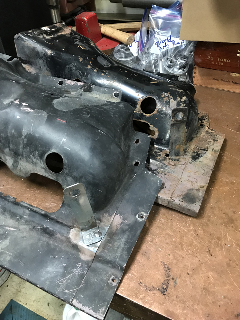
Started fabrication work to address the missing sheet metal section that was cut out of the cylinder 3/4 side tin to accommodate the York compressor.
Here is the start of it. 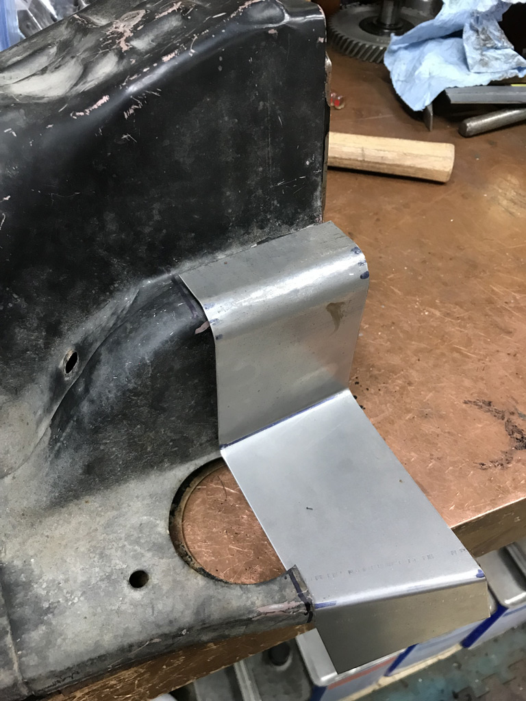
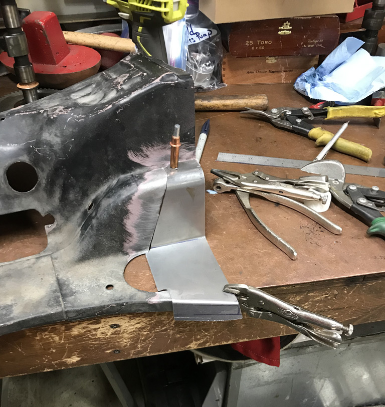
Will finish this up today.
Posted by: Superhawk996 Sep 18 2019, 02:45 AM
Well, 9/17 was my final skin graft surgery so I'll use the downtime to post up some work that I was able to get accomplished prior.
Engine Tin repair was completed. I did use a little bit of silicon bronze TIG rod to help fill in low spots and/or minor porosity to help with quality of final powder coating. 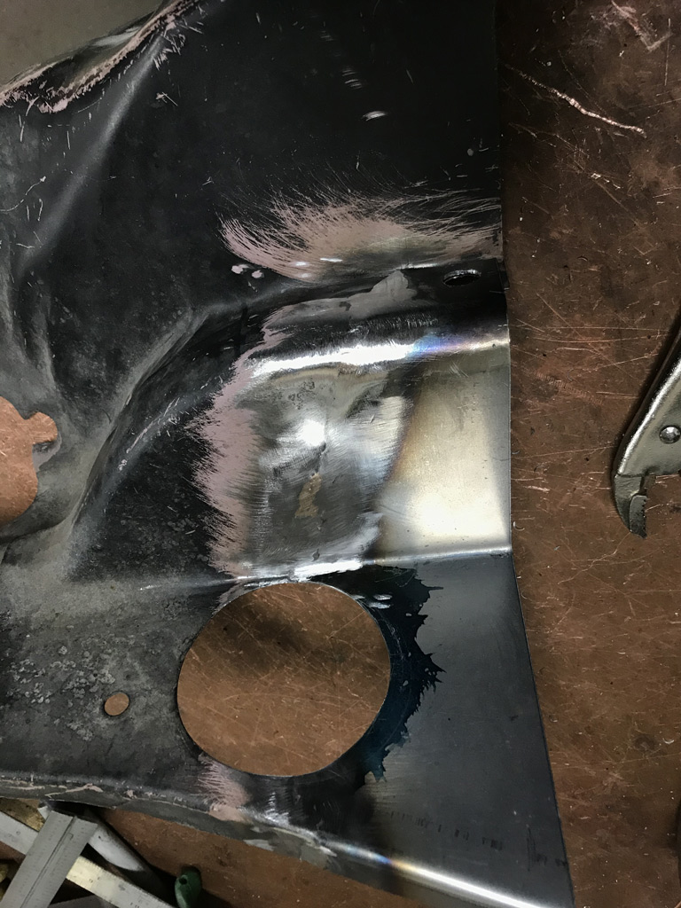
Mocked up to fan tin to determine where hole needed to be. 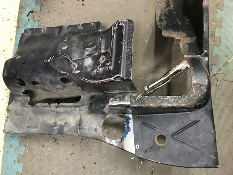
and there you have it A/C butchery repaired. Would have been way easier to buy tin, but, it made more sense to fix this and not break up a full set. 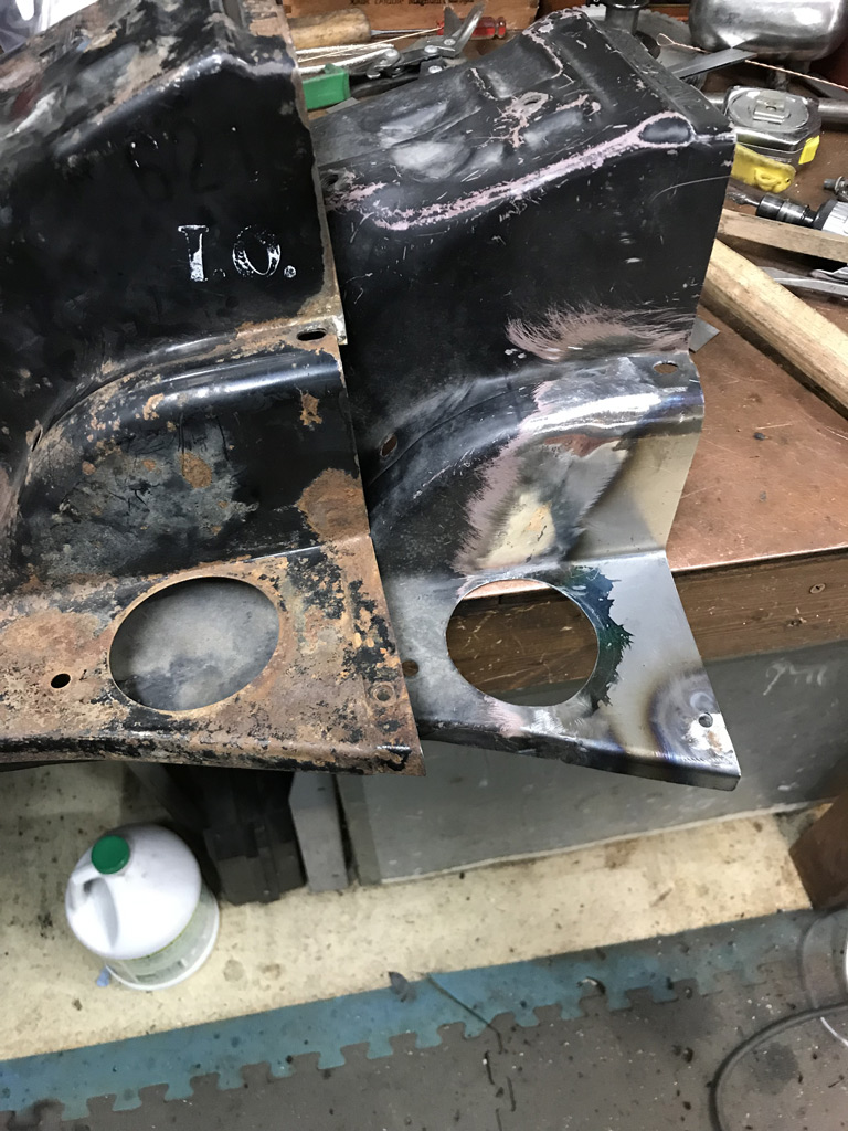
Posted by: Superhawk996 Sep 18 2019, 03:02 AM
Not having enough to do with two 2.0L engines already torn down and and various stages of rebuild, I decided to pull the trigger on the 2.4L six that was floating around over on the Classifieds forum.
You know, cause I really need more to do. But at some point, I have always wanted a 914 with a six. 914/6 prices are in the Stratosphere so a conversion is my best bet to have a six in my lifetime.
The plan:
1) Tear this engine down
2) Figure out what I have
3) Try to recoup some cost by selling off the 1973.5 CIS components to a needy 911 owner
4) Cash flowing the rebuild over time as finances permit
5)Offset this engine cost by selling GA004310 (engine from my car) 1st after it has been rebuilt
6) Selling GA000099 after a year or two when I have this engine rebuilt and the funds for the conversion parts (Need a set of Ben's awesome SS heat exchangers and a nice SS muffler, a DIY oil tank kit, and other hoses, engine mounts, etc.) These costs stack up pretty quickly and will be done over time to ease negative cash flow.
7) Determine induction -- PMO carbs would be nice but I'm contemplating modern MegaSquirt based FI with PMO ITB. Has to have a ITB's or Carbs for that look and oh so sweet induction noise.
8) Question my sanity again!
I want to post up front that this engine was bought as a core, at core price with no assumption that this would be a running motor. Engine was purchased from a terrific guy with no warranty expressed or implied! Thank you for selling this to me.
@http://www.914world.com/bbs2/index.php?showuser=22330
Upon arrival in my garage and finally up on the engine stand after a long drive, and lots of mid-west style sweating. 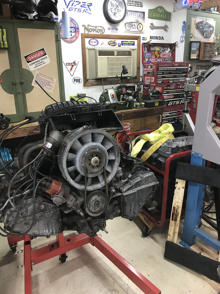
Also right up front I want to reinforce with you guys buying cars and then having overheating problems. Don't assume that the mice haven't set up home while your car and/or engine was in storage.
Here is the standard oil gunk, pollen or cottonwood fluff crap that clogs up oil coolers plus some deposits from Mickey Mouse. 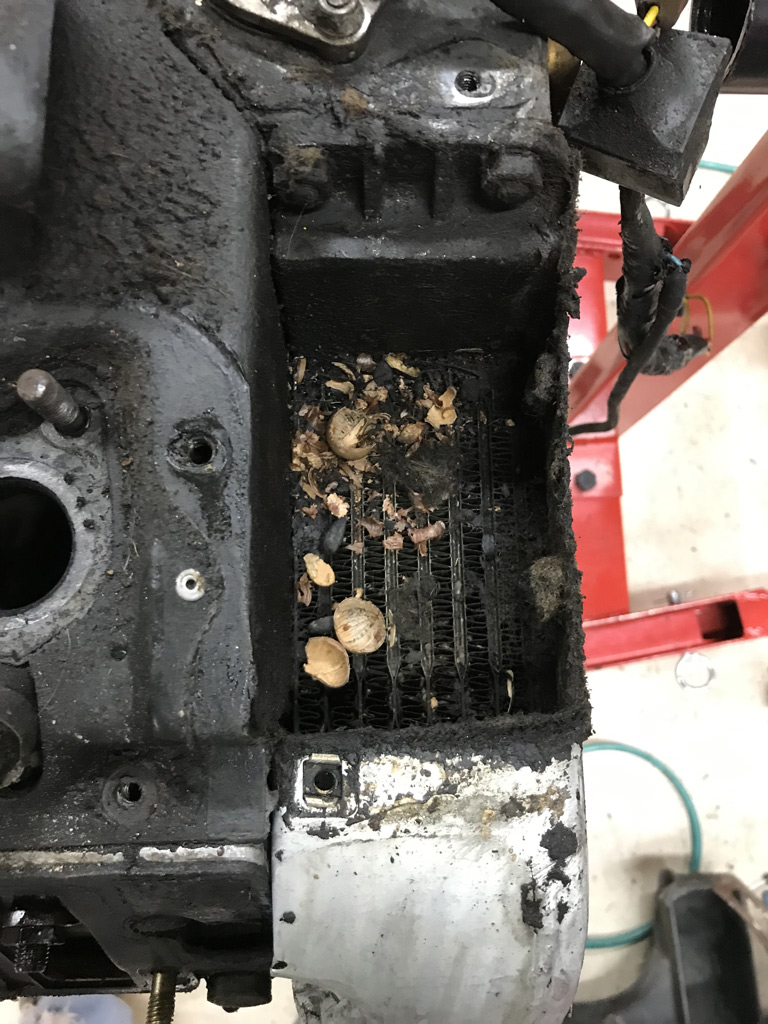
Posted by: defianty Sep 18 2019, 03:02 AM
Nice work.
Posted by: Superhawk996 Sep 18 2019, 03:36 AM
As I mentioned over in the buid thread for GA000099 I absolutely love tearing down old engines.
It is sort of like Christmas. You never know what is in the box. Sometimes its good, sometimes, it's sheer terror.
I purchased it in part because it is a 1973.5 7R motor. My car is a 73'. Seems like a good match to me.
Case shows signs of having been disassembled before as witnessed by RTV sealing the case and timing chain covers + heavily loaded in around the oil return tubes. I'm really hoping that someone didn't cut the cylinder spigots. Cylinders are cast iron so I have high hopes they are 2.4L originals.
Early plan of action:
1) Do leakdown just to see if I got lucky.
2) Teardown completely and assess what I have.
This engine purchase was a bit of a risk due to it being a 1973.5 2.4L and that only being a 1/2 year engine with CIS. The heads are different, CIS parts for 1973.5 are hard to find because, well you know Porsche. They were so hot to do CIS in 1973.5 that they turned around and changed a bunch of stuff for 1974! Hopefully some of this works to my advantage in trying to unload the CIS as a cost offset.
Another risk is that the air box has a ton of dirt in it. This could be debris from storage, engine shipping to Rolinkhaus, or it could be somebody was doing a track day and ingested this crap during an off course shunt. 
When I pulled the CIS boot, at least the throttle body and the CIS valve look to be clean. Not a guarantee a bunch of dirt / dust didn't come through though. 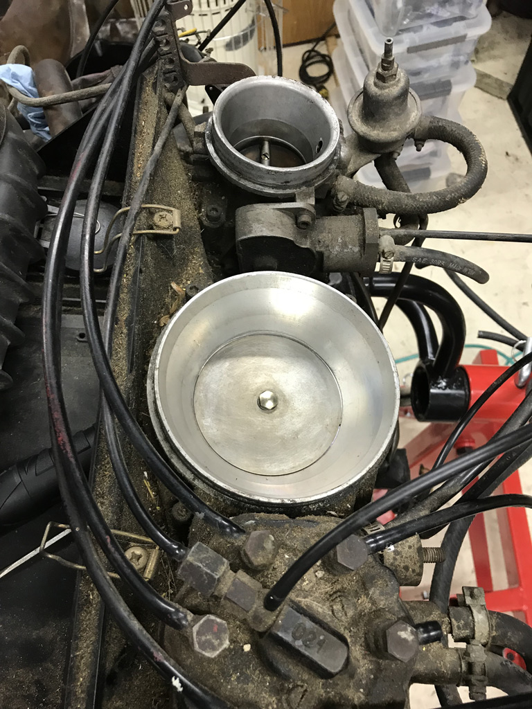
Opening up the rocker boxes to get a look at the valve gear, cams, and to be able to see them in preparation for leakdown checks. 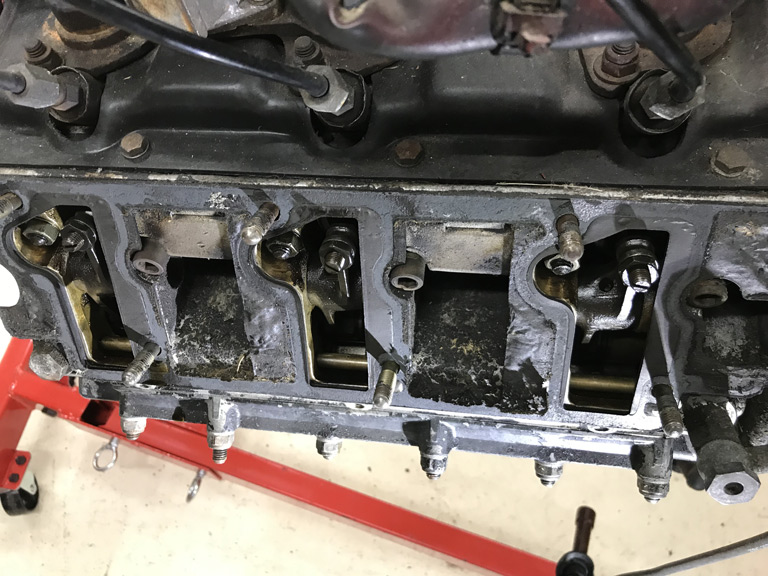
Not pristine but engine was supposedly 90K so not outlandish either.
Between the fact that the CIS internals and the fact that the side of the rocker boxes exposed air aren't covered in dust matching the air box, I'm going to say the airbox dirt probably came during shipping or storage.
Posted by: Superhawk996 Sep 18 2019, 03:47 AM
After pulling all rocker covers, I did a leakdown.
Not so encouraging. Bank 1-3 is 16% to 30%. Definitely rebuild time.
Bank 4-6 is more concerning. Basically, complete blow though with 70-90% leakage. Leaking into the case partially and hard out the exhaust valves. No compression feel when air is applied via the leak down gauge and starting before TDC and cycling up though and past TDC. Nothing . . . Nada. 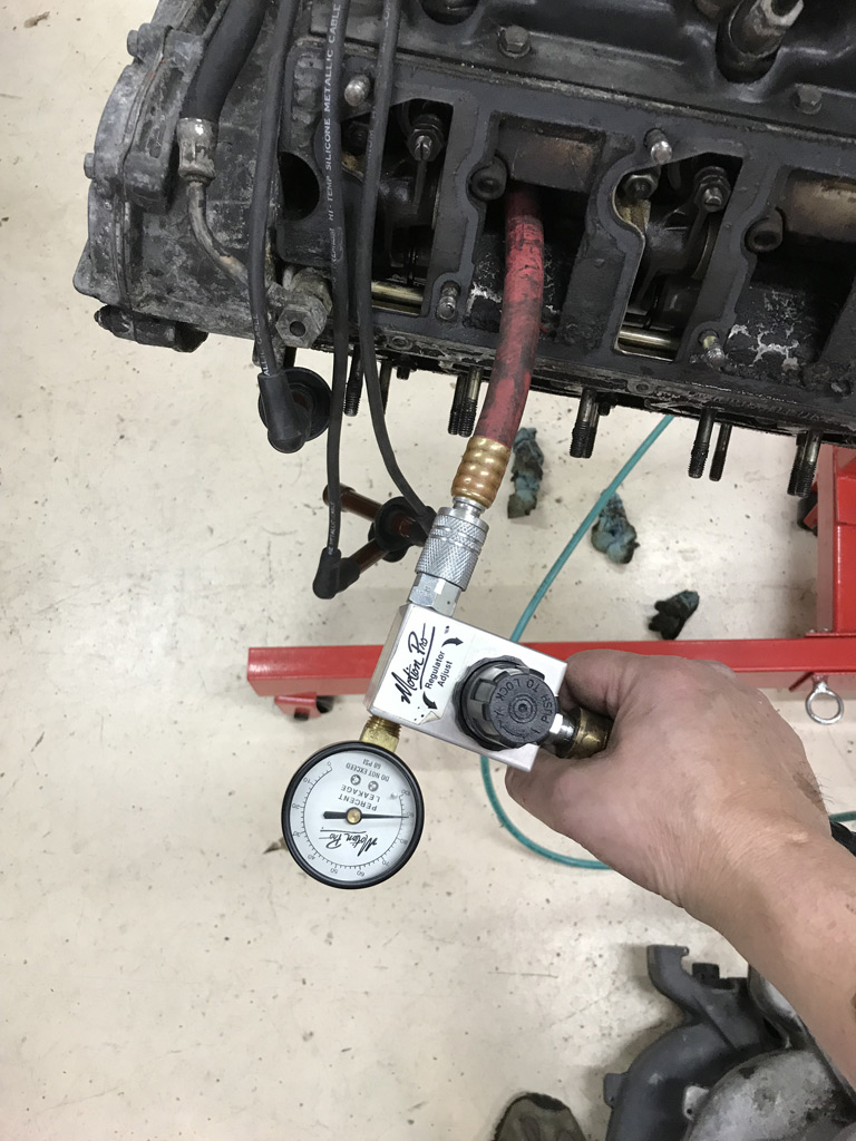
There is a lot going on in my head at this point. This is the sheer terror part! 
Valves seem to have clearance to rockers on the compression stroke so we really shouldn't have this much valve leakage. Might be burned valves.
I did pop a borescope into a couple of the cylinders before I purchased and didn't see any holes or valve heads in there and the engine turns freely. likewise, I can see all valve heads are attached. Whew!
I may go back and back off the exhaust valve adjusters just to be sure but honestly, it doesn't matter since a complete tear down is going to occur.
Posted by: Superhawk996 Sep 18 2019, 03:50 AM
Next order of business is to get the shroud pulled.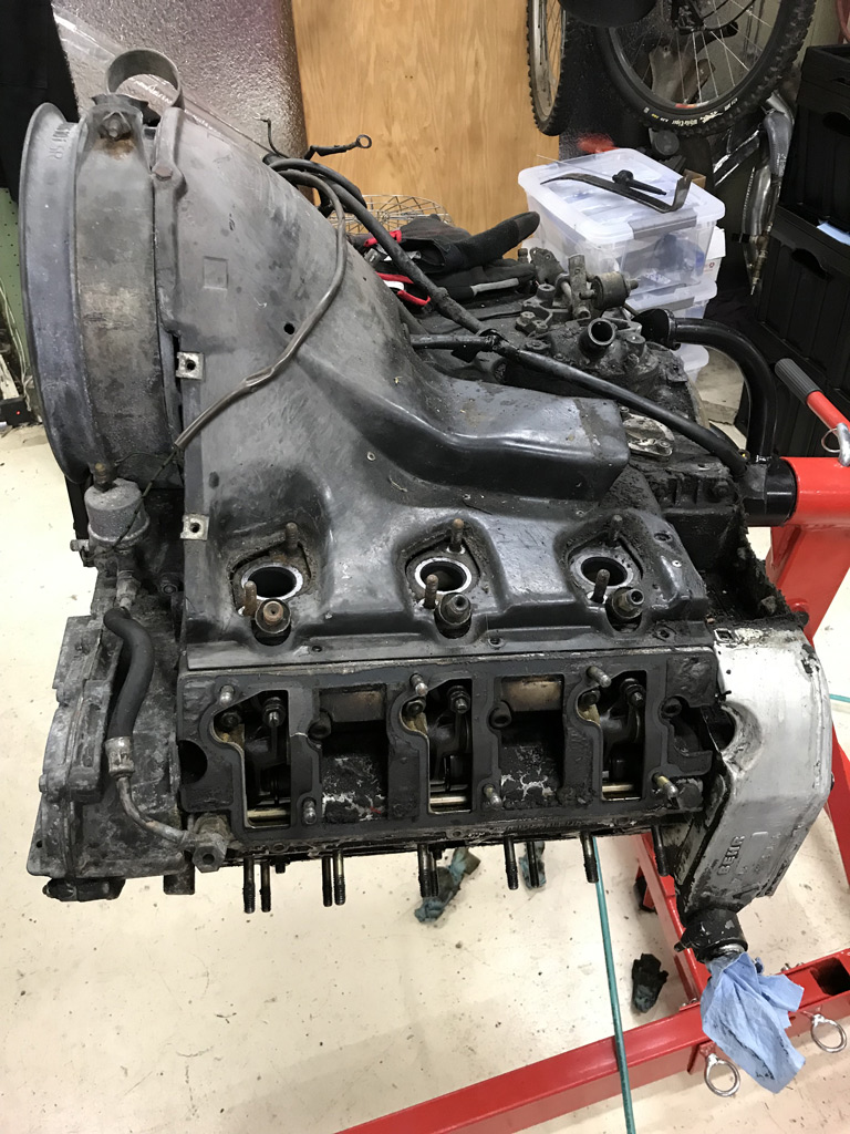
Easier said than done. CIS had to come off which is easy enough but the CIS injectors proved to be a challenge.
I've read all the Pelican forums about how hard these are to pull. I honestly can't imagine trying to do this in car.
I ended up using a slide hammer. I made an adapter to thread onto the CIS injector body and then to get a nice hard straight line pull out. They still didn't come easy.
Posted by: Superhawk996 Sep 18 2019, 04:13 AM
Removal of the shroud came with a few unpleasant surprises. Like all machinery of this age, it has been abused at some point in it's life.
This one appears to be no exception.
I found the fan housing to be cracked and a slight chip out of the backside of one of the fan blades. Most likely from an inept mechanic trying to wedge a screwdriver or pry bar between the fan and the housing to loosen the fan belt nut rather than using the proper holding tool.
You would think Porsche 911's might get a touch better attention than the 914's. . . but nope! Not if you happened to be in Iowa in 1974 and needed a fan belt replaced. Sorry - not trying to pick on Iowa . . . . just an analogy. Could have happened as easily in Detroit back in the day! 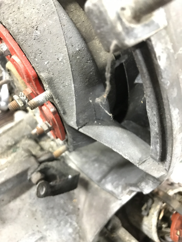
I've got to say, I'm continually confounded by American mechanics that never seemed to really grasp things like Magnesium.
1) It isn't as strong as cast iron and deserves a little more respect.
2) The legend that it can't be welded without starting on fire.
I also found this cracking on the case. The case is the desirable 7R case and is the bulk of the reason I chose to purchase this core.
I think this is just casting shrink at the casting gate where molten metal flows into the mold. The gate intentionally provides a place for metal to shrink from when the casting cools.
The fact that there is no oil residue here likely means this doesn't penetrate the case. We'll see when I get the case split. I'll keep my fingers crossed that it is indeed gate shrinkage. Or worst case, it is repairable by Otto's or the like. 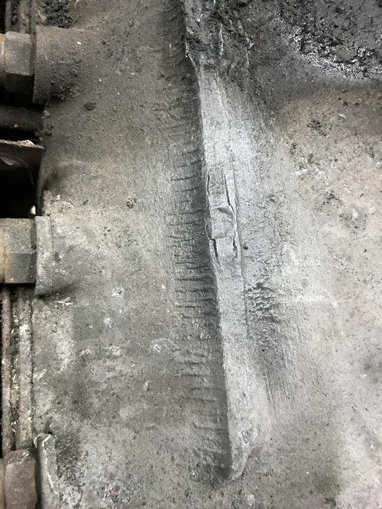
Posted by: Superhawk996 Sep 18 2019, 04:19 AM
So finally after much cursing and a little more disassembly, I finally got it down to a long block. 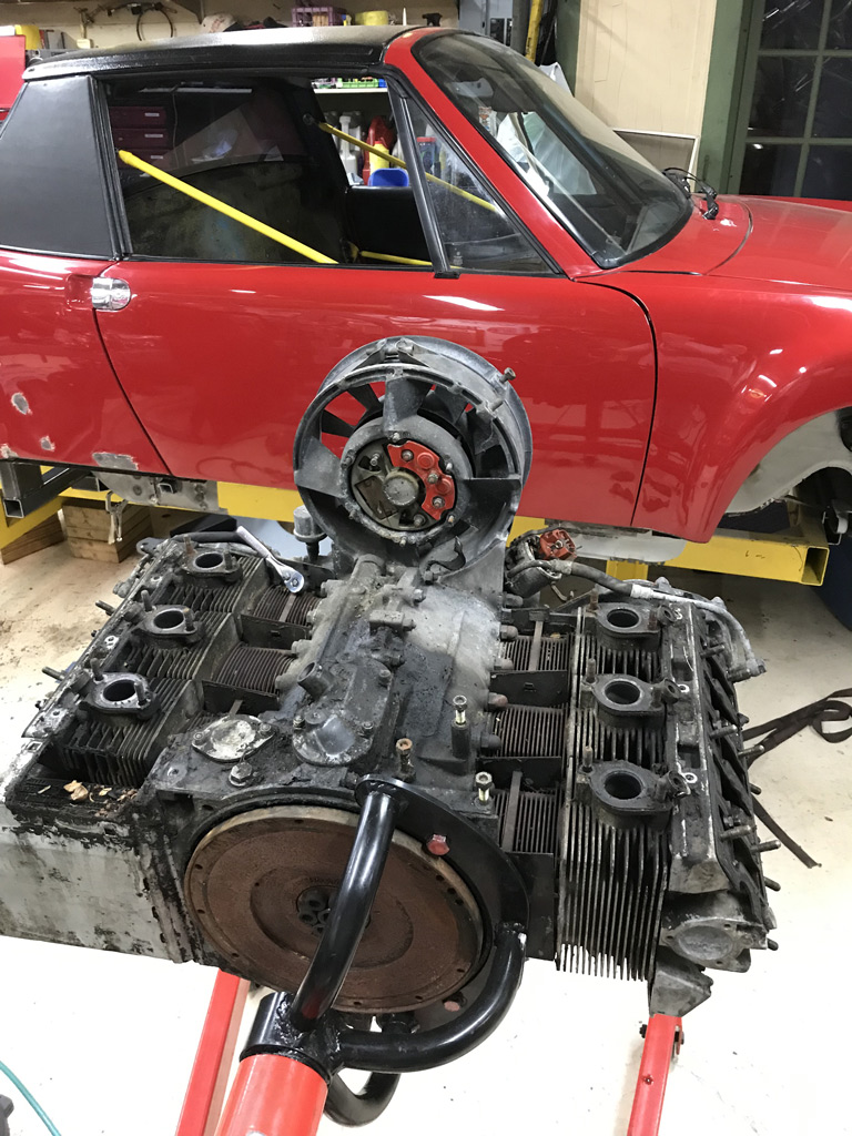
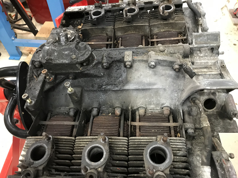
This is the current state of affairs.
Once I'm past this 2nd day of post surgery pain, I'll get back out into the garage and start working toward a complete teardown and determination of what's going on over on the bank 4-6 side of the engine.
Posted by: bbrock Sep 18 2019, 04:31 AM
Your sanity was never in question. It's 5am and you are posting on this forum Then again, it is 4am here and I'm reading... 
Your project(s) escalated quickly from insisting on dished 94mm pistons for your 4. Looking good!
Posted by: Superhawk996 Sep 18 2019, 04:43 AM
Your sanity was never in question. It's 5am and you are posting on this forum
Then again, it is 4am here and I'm reading... Your project(s) escalated quickly from insisting on dished 94mm pistons for your 4. Looking good!
@http://www.914world.com/bbs2/index.php?showuser=20845
Pain from surgery not allowing me to sleep. What's your excuse? Burning the 4am oil and getting an early start on the 914 today I hope. I hope you can get your paint work done before snow flies and/or that you can move indoors with a temp paint booth arrangement.
Yeah. I was just going to post on that topic of the NOS parts.
@http://www.914world.com/bbs2/index.php?showuser=20991
Jeffrey sure went out of his way and to extraordinary measures to hook me up on those 94mm KS NOS pistons, cylinders and NOS cam.
I had a long phone conversation with him about what is the right thing to do. I wanted to make sure that he is 100% on-board with the plan before I do anything.
So I think what is going to happen is:
1) I'll reassemble GA000099 with existing 94mm low dish P&C's which are in good shape and came out of this engine. I'll likely, use the original un-cracked Porsche 2.0L heads (after rebuilding those). Regrind the slightly worn stock cam that came out of this engine and put on stock FI. That gets me a stock NOS 2.0L for use until the six conversion can happen. This keeps an interesting low serial number GA engine NOS.
I'll drive this until I can fund the 2.4L engine rebuild and conversion. 2) I'll rebuild GA004310 with the 2.0L AAP heads prepped by HAM, and 96 mm P&C's. I think it will be easier to unload a 2056 with HAM heads as a cost offset for this 2.4L 911 engine. The catch will be if I can actually make any money for my rebuild time and effort. Doubt it. I at least need to recoup the costs.
I've thought of selling off the new unused HAM heads, the case, 2.0L tin, crank, etc. as parts but I suspect there will eventually be someone that needs a properly rebuilt 2.0L that doesn't have the means or time to DIY. Might be a long wait though vs. just parting out. Plus, selling parts piecemeal is a pain for me with all the postings and subsequent shipping time, etc. Or, list as a lot price for engine core parts? Undecided. 3) The KS 94mm pistons, cylinders and cam stay NOS and unused. It would be a shame to put into an engine just to drive it a year and then sell to someone that doesn't fully appreciate a stock 2.0L. Parts get put on the shelf for the next guy that wants to build up a 2.0L engine with 94mm NOS parts and really values that.
Open to better options but this is what Jeffrey and I came up with.
Posted by: 914_7T3 Sep 18 2019, 10:33 AM
Your sanity was never in question. It's 5am and you are posting on this forum
Then again, it is 4am here and I'm reading... Your project(s) escalated quickly from insisting on dished 94mm pistons for your 4. Looking good!
"Your project(s) escalated quickly........................................."
and it's more like your insanity was never in question
Posted by: euro911 Sep 18 2019, 12:57 PM
I'm undecided on next steps for this head. I hate to toss a 2.0L head. May weld it but that will be down the road since it will involve lots of work to weld it and then to re-machine the valve guide boss properly. I will probably bead blast it just to see if there are other cracks in the combustion chamber to help seal the deal.
Ah . . . the joy of restoring 40+ year old cars.
Even when rinsing the parts in an ultrasound tank, you may not dislodge all the beads. They'll eventually come loose while you're driving 90 mph on the turnpike
That's why I'm building a new soda blasting cabinet ... I have numerous parts including carburetors that I need to clean up.
Posted by: Superhawk996 Sep 18 2019, 02:55 PM
I'm undecided on next steps for this head. I hate to toss a 2.0L head. May weld it but that will be down the road since it will involve lots of work to weld it and then to re-machine the valve guide boss properly. I will probably bead blast it just to see if there are other cracks in the combustion chamber to help seal the deal.
Ah . . . the joy of restoring 40+ year old cars.
Even when rinsing the parts in an ultrasound tank, you may not dislodge all the beads. They'll eventually come loose while you're driving 90 mph on the turnpike
That's why I'm building a new soda blasting cabinet ... I have numerous parts including carburetors that I need to clean up.
In the case of heads, All valves, guides, etc. come out. No where for the bead to get stuck. Agree completely if the heads were not to be fully disassembled.
Whenever I've done a case, it is exterior only and all oil galleys get sealed off and ultimately galley plugs will get pulled anyway to ensure no other 40 year old debris resides within the galley.
Agree soda is a better choice but let's be honest, walnut shells and bead have been a mainstay for years before anyone came up with soda blasting. Even better yet is Dry Ice blasting which leaves absolutely no residue. I'm still waiting for someone to come up with an affordable dry ice blaster though.
It all comes down to diligence in getting things totally clean inside and out before assembly. That is true for any engine rebuild be it a lawn mower or a high end race engine. If I can't eat off of it, it isn't clean enough.
Posted by: Superhawk996 Sep 18 2019, 03:04 PM
and it's more like your insanity was never in question
Have to agree with you on that. Had I been sane, I would have started with a beautiful rust free CA car. I'd be driving by now.
Posted by: euro911 Sep 18 2019, 06:32 PM
Even some folks who have rust-free cars still don't have them on the road after more than 10 years.
Ask me how I know
Posted by: Superhawk996 Sep 28 2019, 10:55 AM
OK - Feeling better and getting back at it.
1st order of business was to get the right side cylinder bank heads off to see what happened. The curiosity was killing me. 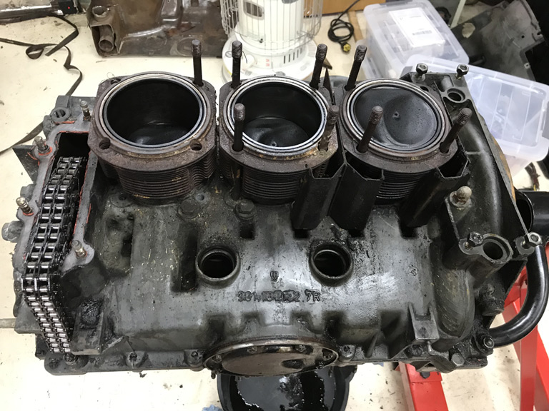
When the cylinder heads finally came off the problem is obvious. Mr Piston met Mr Valve. 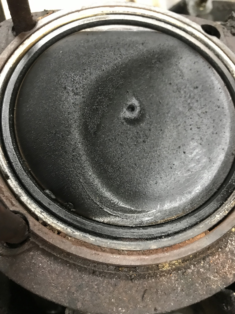
In addition cylinders 4,5, and 6 are trashed. Multiple causes here. Storage and corrosion are one issue but there is evidence in cylinder #4 that the cylinder is pretty torn up probably from deformation and side load of the piston when it met the valve.
Hopefully rods are OK but we'll figure that out later when I finally split the case.
On the head side, at least all the valves are intact but they are surely bent based on the leakdown test and the air escaping via the exhaust valves. Not a big deal, valves would be replaced anyway. Will have to wait to later to get a good look at the valve guides and particularly the casting around the valve guide. 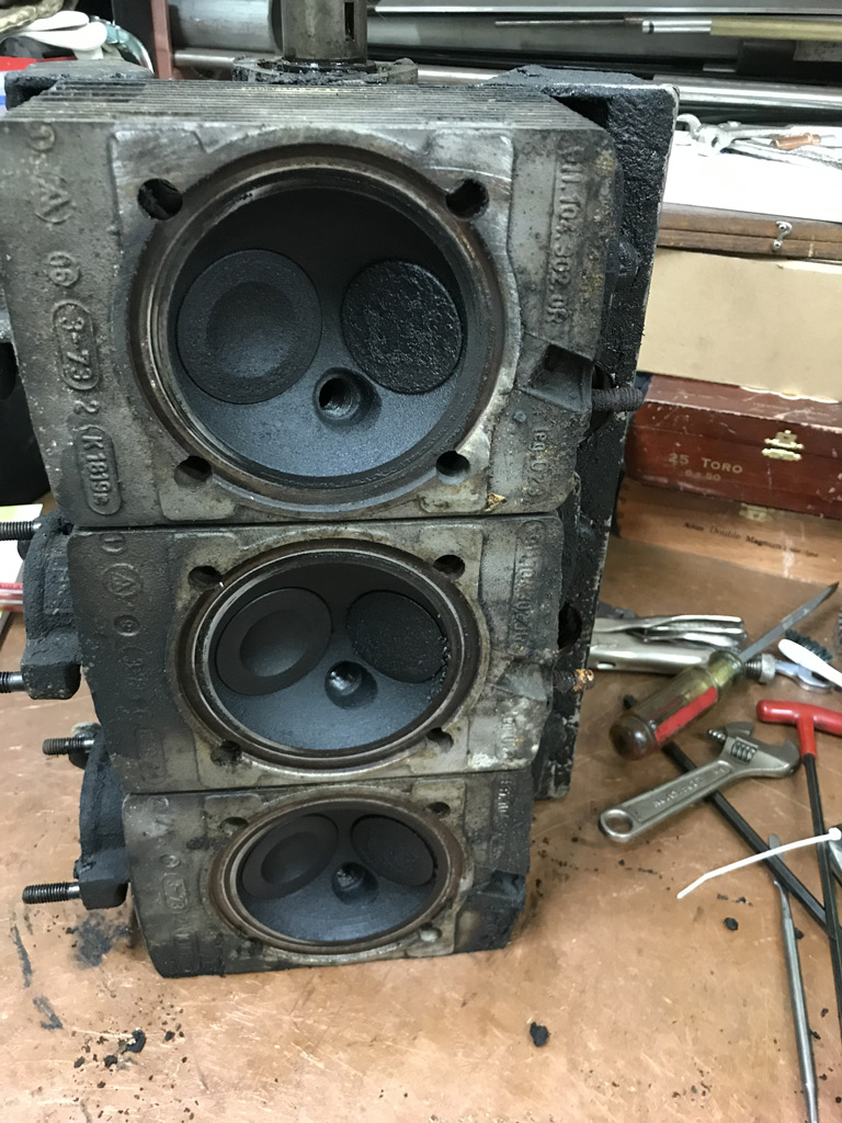
Well, at least now I know what happened.
Doesn't appear to be catastrophic at this point but I certainly will need to do so measuring on the granite surface plate to see if the rods are bent.
Posted by: Superhawk996 Sep 28 2019, 11:14 AM
Now here's the real mystery.
I'm a bit embarrassed to post the carnage to the CIS injector cups but I'm here to share the good, the bad, the ugly so you can learn from my own impatience with trying to get a cup out. This was literally a 1/2 model year solution by Porsche for 1973.5. For 74' the CIS injectors were moved up into the intake runners and have a proper insert in the runner to both insulate it from heat, and to seal it. The 74' CIS injector insert is serviceable. Imagine that. 1973.5 maybe not so much.
In the process of pulling the CIS injectors the rubber seals were so hard, I couldn't get the injectors out even when I heated them gently to "operating temperature" to try to soften the rubber. I'm sort of wondering what other trick might have been tried to soften the seals enough to allow the CIS injector to pass out without blowing out the thin wall cup perimeter. After the fact, I thought of maybe a solvent to soften the rubber. Too late!
As the CIS injectors came out, they trashed a couple of the CIS injector cups. Not really a concern since I'll end up either running carbs or more likely ITB's and modern FI via MegaSquirt. These cups need to go and get the holes tapped for plugs if they are not already tapped.
Before I bought the engine I did some research and thought the cups were threaded into the early 73' MFI threads. It is looking like that is not the case. Information on how to remove them is pretty much non existent. I did find one instance where someone converted to carbs and just make "plugs" to fit into the seals and cups were the CIS injectors were previously. That would work, but I'm to OCD for that. The cups need to go bye bye.
A post over on the bird came up with one fellow that indicates the CIS cups are press or shrink fit. They don't appar to be designed to be serviceable. I couldn't find them in the PET parts guide. Strangely, the crude ISO view seemed to show one on the head assembly but no separate part available. Not a good sign that they were ever intended to be serviceable.
Worst case I'll machine them out in the mill. 
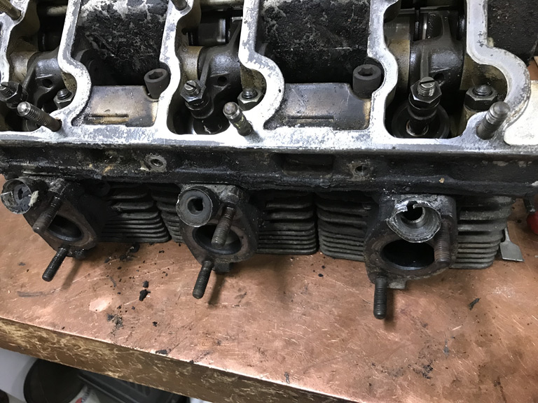
Posted by: Superhawk996 Sep 28 2019, 11:30 AM
Given that I now have three engines in pieces, keeping the balls in the air is getting tricky.
All the tin from the two 2.0L engines (GA004310 & GA000099) was dropped today for sandblasting and powder coat. One set will be done in black, one in red for my project.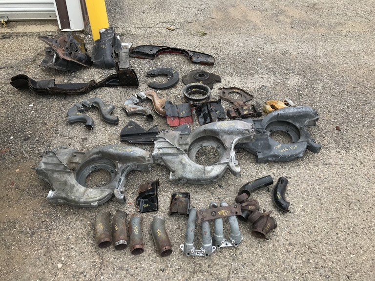
There are three fan shrouds because back when I needed flaps, I purchased a complete shroud off e-bay just to get the flaps.
All fan shrouds will be done in silver. Don't worry, I'll clean off the powder coating at the attachment points to make sure I have a good ground between the shroud and the case.
The extra shroud will go up on classifieds forum in a couple weeks when it's complete.
Posted by: bbrock Sep 28 2019, 01:39 PM
I've never touched a real Porsche engine so am learning here. Hard to believe those injector cups came from German engineers. What was the purpose of mounting them in the heads vs intake runners? Better spray pattern?
Posted by: mepstein Sep 28 2019, 01:53 PM
I've never touched a real Porsche engine so am learning here. Hard to believe those injector cups came from German engineers. What was the purpose of mounting them in the heads vs intake runners? Better spray pattern?
Porsche made so many changes on their engines from year to year. Some were good, some not so good. We have about a thousand heads on the shelf and it's often hard to match up 6 since they made so many changes and had different port sizes and injectors for carbs, MFI, CIS, T,E S, Turbo, 2.0, 2.2, 2.4, 2.7, 3.0, 3.3, etc.
Posted by: Superhawk996 Sep 30 2019, 07:03 PM
After much sweating and maybe a little swearing here is the weekend scoreboard.
Headstuds: 23 of 24 removed without lifting out the magnesium threads. There is always that one that refuses to go along with rest.
P&C's
Yup, the 1,2,3 bank pistons also kissed the heads. I guess that makes a perfect score of all 6. At least we have consistency.
Crankshaft:
Visually looks good. only the lightest of scoring that can't be felt with a fingernail. Standard bearings in place. 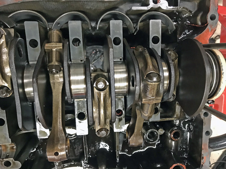
Case:
With respect to the previously mentioned casting gate, the shrink is over the main webs, in a very thick section, and is indeed casting shrinkage. No chance of perforation of the case.
Initial visual upon 1st splitting the case was great.
But, then I got to bearing #7. Not good. Something went very bad. Either casting porosity, corrosion, or major fretting. I don't see any fretting on the other bearing web's. Likewise this is the only place inside the case that looks like this. I'm going to rule out corrosion as I can't see how it would be localized to just one web. That leaves casting porosity as the likely suspect. 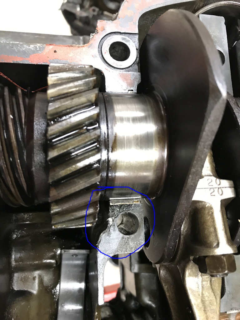
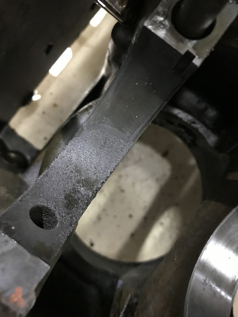
I had planned on this being a core engine and needing machine work. Sent pictures to Ollie's today and they think all can be made well in exchange for $$. Likely to be on the order of $2600 to include potential welding, machining, line bore, adding case savers, oil bypass modification, extraction and repair of a couple transmission studs, etc. Life if good if you're Ollie! 10-12 week lead time to even get to it. Good thing I have at least a year!
Overall not a bad weekend! Beats being at work but I had to go back today to pay for this endeavor.
Posted by: mepstein Sep 30 2019, 07:12 PM
Just saying...
Attached thumbnail(s)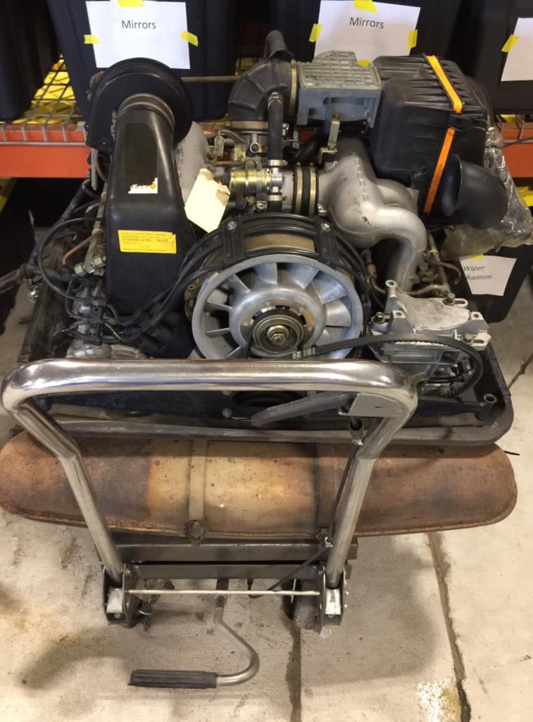
Posted by: Superhawk996 Sep 30 2019, 07:23 PM
@http://www.914world.com/bbs2/index.php?showuser=10825
You had me tempted but I'm not a chase the HP kind of guy. I will actually have more fun driving this car as a 2.0L Type 4 for a year or so and then go to the 2.4L when parts and funds permit.
I personally think 2.4L is the sweet spot for a six and the 2.0L for the type 4. I also wanted to keep a period correct engine. 1973.5 2.4L could have just as easily been installed by Porsche had they not been afraid the 914 would outperform their beloved 911.
7R case not highly stressed. 140-160 HP is just right for the type 901 trans to avoid having to baby it, or update to a 915.
Keeps a nice balance of HP vs. handling with an emphasis on handling.
Posted by: Superhawk996 Sep 30 2019, 08:03 PM
I've never touched a real Porsche engine so am learning here. Hard to believe those injector cups came from German engineers. What was the purpose of mounting them in the heads vs intake runners? Better spray pattern?
@http://www.914world.com/bbs2/index.php?showuser=20845
I think it was part of the learning and evolution. Evolution from Carbs to MFI was great for HP but costly. CIS was next logical step to bring down cost without hurting HP and CIS probably had an emissions advantage in an era where emissions controls was ramping up.
MFI was always in the heads. I think when they did the 1973.5 CIS they didn't have time to get the 74' intake runners tooled up for production so they put the CIS injectors in the heads for expediency. This caused issues with vapor lock and carbon deposits on the CIS injectors similar to what happens on the back side of an intake valve.
Moving the injectors to the intake runners yields better atomization, less carbon, and less vapor lock potential.
Given that I could see the need to quickly migrate from MFI to CIS I assumed they would just make an injector cup / adapter that threaded into the MFI ports. Silly me.
What did amaze me though was just how thin the aluminum cup is. It literally cracked when the rubber injector seal wouldn't yield from rubber hardening. another 0.020" of wall thickness would make these very robust. No idea why they made them so thin.
We all like to think Porsche was pretty smart but given the issues I've seen now with the GA000099 casting (early 73') and this 1973.5 911 case, I think quality control was . . . ahem . . . lacking in that era. Too much dope smoking is what I'm going to pin it on!
I don't have much memory of 1973 other than moving from Massachusetts to Michigan. I was only 6. However I vividly recall 1975-1976 and there was plenty of dope smokin' going on around me with friends older brothers and what not!
Posted by: sixnotfour Oct 1 2019, 09:44 AM
Wow, that sucks.weird porosity down in oil hole too ?? Here is my oh-shit, numbers matching -6 case , spun main bearing..... 
Attached image(s)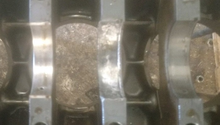
Posted by: Superhawk996 Oct 1 2019, 10:31 AM
Wow, that sucks.weird porosity down in oil hole too ?? Here is my oh-shit, numbers matching -6 case , spun main bearing.....
Yeah porosity appears to be in the oil hole too. Someone not paying attention in the foundry and/or Porsche was willing to accept it. Hard to tell which was the case.
The good news for both of us it can be fixed with Welding, machining and line bore. Like mine the bad news is the cost to do so.
There is very little that can’t be fixed. The issue is always cost and timing.
Seems like it would be worth the cost to keep matching numbers on a -6.
Posted by: mepstein Oct 1 2019, 10:53 AM
We are seeing this often on 2.7’s
Attached thumbnail(s)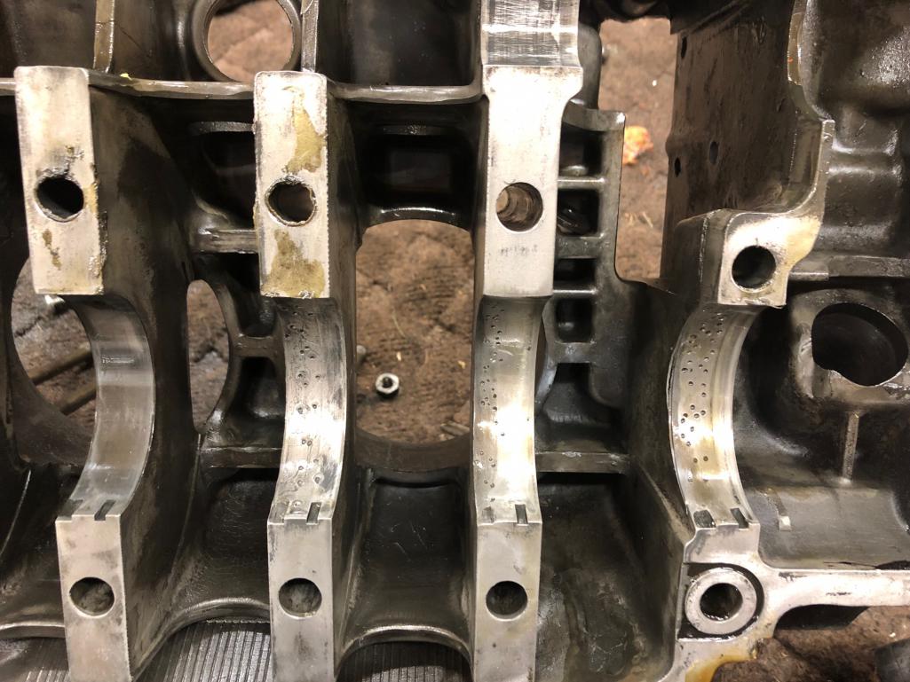
Posted by: Superhawk996 Oct 1 2019, 11:02 AM
We are seeing this often on 2.7’s
Apparently 1974 casting process was getting getting better with time.
Honestly there will always be some porosity in castings. In my case it seems a bit excessive but honestly it isn’t a show stopper at 140hp which isn’t going to flex or fret the case as much as a 2.8L RSR !
I’m just OCD and want it to be the best I can manage within my budget.
Posted by: mb911 Oct 3 2019, 06:54 PM
Also know that there is considered "acceptable" levels of porosity with magnesium and welding per all FAA repair manuals which is considered the holy grail of weld repair of magnesium
Posted by: Superhawk996 Oct 3 2019, 07:27 PM
@http://www.914world.com/bbs2/index.php?showuser=9892
You are correct for sure.
The porosity in the saddle is less concerning to me since that has a large surface area that the bearing load is shared over.
The main thing I don't like is how the end of the shell bearing is left unsupported right there at the case split line.
The case will need case savers, the oil bypass modification, and a few broken studs on the transmission end that will need to be repaired anyway so it wasn't as if I was expecting a pristine case. I'll measure case main bearing bores to see if they are oval. If they are still circular then it will be a much tougher call on the welding, case machining, and subsequent line bore that creates its own set of compromises.
I would have expected that certain areas of the case would be deemed critical and would be under higher quality control. Just seems odd that they would accept that defect that leaves a portion of the bearing unsupported albeit only slightly.
Posted by: GTSandberg Oct 4 2019, 07:20 AM
Inspiring thread, lots of knowledge and know how! Always encouraging to see people diving in to even more challenging project than your own
Posted by: Superhawk996 Oct 9 2019, 06:49 PM
Continued tear down of the case has finally resulted in a "basket case" engine. No more big parts sitting around. Everything now fits in bins! It's nice to have my limited floor space back.
I got the crank torn down. Still need to measure all the journals. Overall, the bearings are showing wear consistent to a high mileage core. It was purchased with the understanding that it probably had 90K on it. I'd say that is probably accurate based on bearing wear.
Crank and crank bearings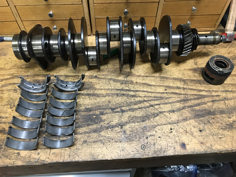
Rod bearings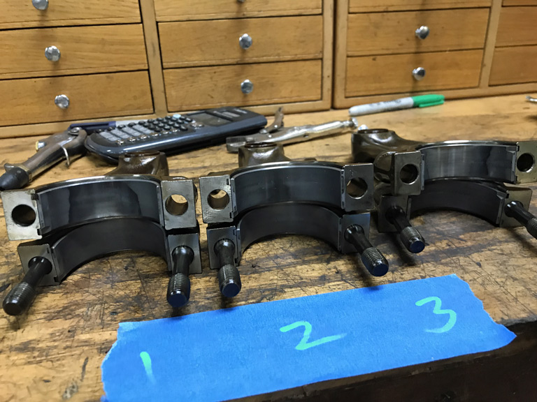
IMS bearings. 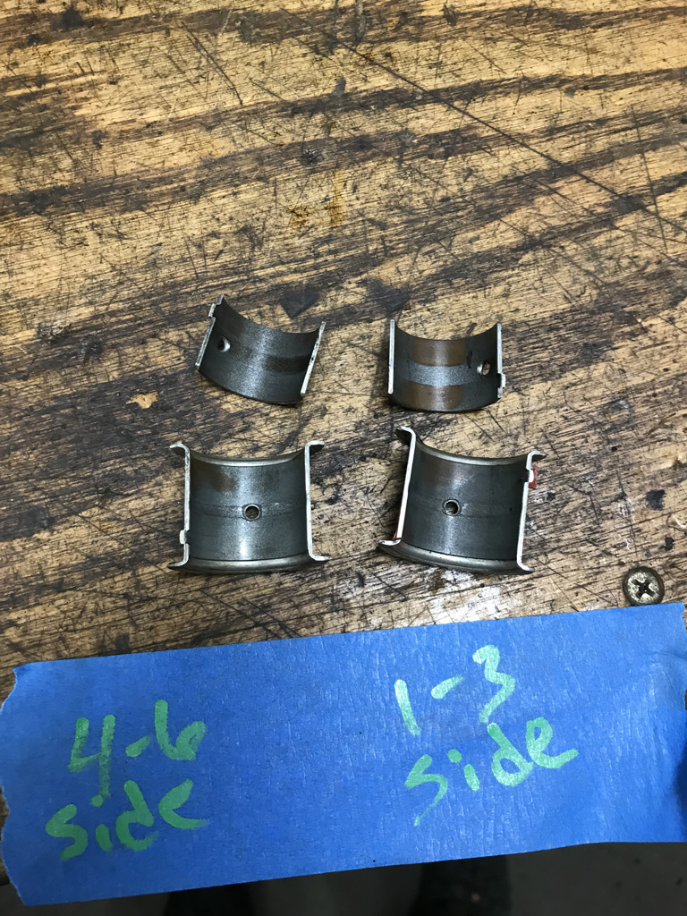
Next step is to get the bulk of the oil residue cleaned up off the case internals and to get it ready for shipping to Ollies.
Posted by: 914forme Oct 10 2019, 07:11 PM
You ever thought about picking up another case? I have a few just a few hours south. PM me if you want to talk it over.
Posted by: porschetub Oct 10 2019, 08:49 PM
Looks like that case has been 'fretting" on the bearing saddles,that shows in the main bearing wear,lots of excess point loading due to the case being out of round.
Best to replace the case as the work to fix what you have isn't a good $$$ solution,go for a case half machining and a linebore to resize to std main bearings,you appear to have the skills to do the rest yourself.
Good luck.
Posted by: Superhawk996 Oct 13 2019, 09:13 AM
Spent some time wrestling with parts.
I finally got time to get the fan, alternator, and the fan housing separated.
1) Non OEM alternator - when I pulled the fan shroud, I found a SEV Marchal alternator tag sitting on top of the engine. I had hoped as a long shot that maybe the engine would still have the original alternator. No such luck. Generic rebuild. 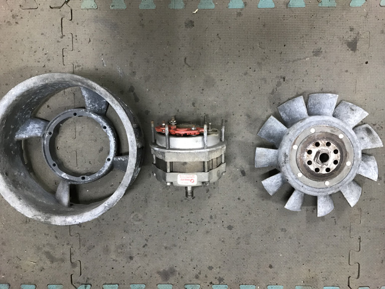
2) I wanted to get a better look at the fan housing cracking. A bit worse than hoped. If anyone has a spare 901.106.101.5R housing sitting around in good shape PM me. Otherwise, this one will likely go to Ben for welding and I'll have to do machine work to clean it back up. 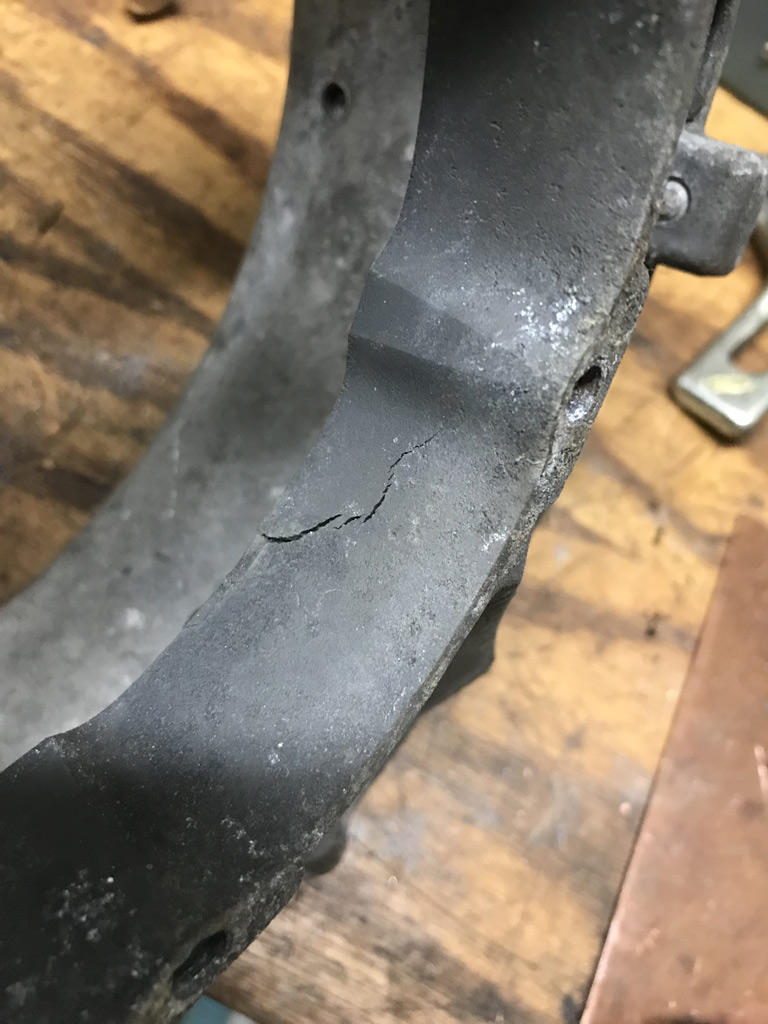
3) Someone savaged the fan hub. It is still useable but it looks like someone went after it with a cut off wheel - probably to clean up botched workmanship when the alternator was replaced. Damn Hacks! 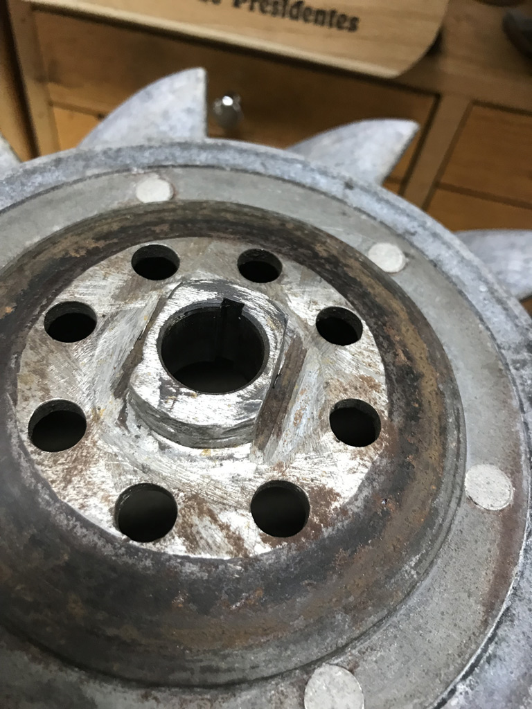
My bet is that some shade tree / low end mechanic is responsible for all this.
One blade of the fan has a small chip out of it. Probably from wedging a tool between the fan and the housing to try to loosen the pulley nut rather than using the proper tool.
That likely lead to the cracked fan housing which then propagated over time.
45 year old parts!
Posted by: Superhawk996 Oct 13 2019, 09:27 AM
Also had more fun than a barrel of monkeys trying to pull broken, damaged and corroded exhaust studs.
So far I'm 7 for 12 but wasted a ton of time trying to get the last 5. I started soaking with penetrating oils 2 weeks ago. All my usual tricks seem to have failed me on the last 5. Ollies charges $22 drill them out,so at this point, it seems more cost effective to just pay the $110 to get them drilled rather than to keep wasting my time. Heck, it would take me longer just to set them up in my mill than the $110 of time is worth. I'm sure Ollies has a nice jig that makes quick work of them. Heads need full rebuild anyway due to bent valves, and valve guides that are worn. 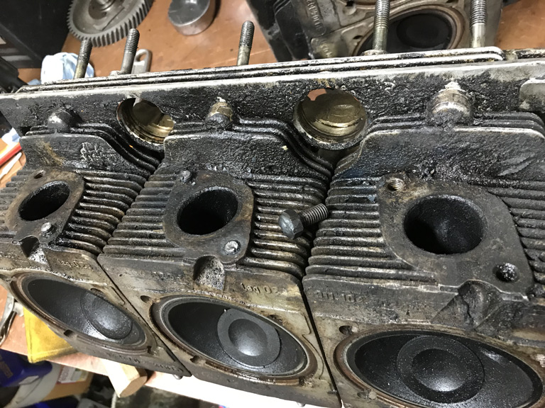
Thought it might be great opportunity to buy another cool tool from Stomski Racing, but, the cost of the tool is more than the cost to have it done by Ollies. Plus Stromski the drill jig counts on having at least one good stud to secure the tool to drill the other. Cool tool though but it is pricey. Would be worth it though if you had to do this under the car. No new tool for me!
https://www.stomskiracing.com/products/exhaust-head-stud-repair-kit
Posted by: Superhawk996 Oct 13 2019, 09:32 AM
Looks like that case has been 'fretting" on the bearing saddles,that shows in the main bearing wear,lots of excess point loading due to the case being out of round.
Best to replace the case as the work to fix what you have isn't a good $$$ solution,go for a case half machining and a linebore to resize to std main bearings,you appear to have the skills to do the rest yourself.
Good luck.
@http://www.914world.com/bbs2/index.php?showuser=18995
Agree that there is some fretting of the bearings there but that really shouldn't be surprising on a high mileage (90K) case.
Problem is I REALLY want the 1973.5 7R case because it matches the vintage of my car. Machining the cases and a line bore back to standard is pretty much a given for these old Mag cases so I'll just roll with the punches and get it fixed properly.
Hope to get the case boxed up and ready to ship today.
Posted by: bbrock Oct 13 2019, 11:34 AM
Those @#$% exhaust studs. About a third of my head rebuild bill was for extracting and replacing studs and busted engine tin screws. And that was for a /4
Bummer about no new tool. You'll just have to keep playing with the old one.
Posted by: mepstein Oct 13 2019, 12:09 PM
Also had more fun than a barrel of monkeys trying to pull broken, damaged and corroded exhaust studs.
So far I'm 7 for 12 but wasted a ton of time trying to get the last 5. I started soaking with penetrating oils 2 weeks ago. All my usual tricks seem to have failed me on the last 5. Ollies charges $22 drill them out,so at this point, it seems more cost effective to just pay the $110 to get them drilled rather than to keep wasting my time. Heck, it would take me longer just to set them up in my mill than the $110 of time is worth. I'm sure Ollies has a nice jig that makes quick work of them. Heads need full rebuild anyway due to bent valves, and valve guides that are worn.
Thought it might be great opportunity to buy another cool tool from Stomski Racing, but, the cost of the tool is more than the cost to have it done by Ollies. Plus Stromski the drill jig counts on having at least one good stud to secure the tool to drill the other. Cool tool though but it is pricey. Would be worth it though if you had to do this under the car. No new tool for me!
https://www.stomskiracing.com/products/exhaust-head-stud-repair-kit
We have the entire catalog of Stompski tools. Great stuff. We use the stud tool but most of the time just leave them in and the machine shop removes them while rebuilding the heads.
Posted by: Superhawk996 Oct 13 2019, 05:08 PM
Well each day it seems I have a couple of wins and couple of losses.
Let's cover the win 1st.
I finally got the funky 1973.5 2.4L CIS injector cups out of the heads. Turns out they are indeed a press fit.
I created a tool from some scrap material that let me pull them with a slide hammer and some gentle heating of the head. 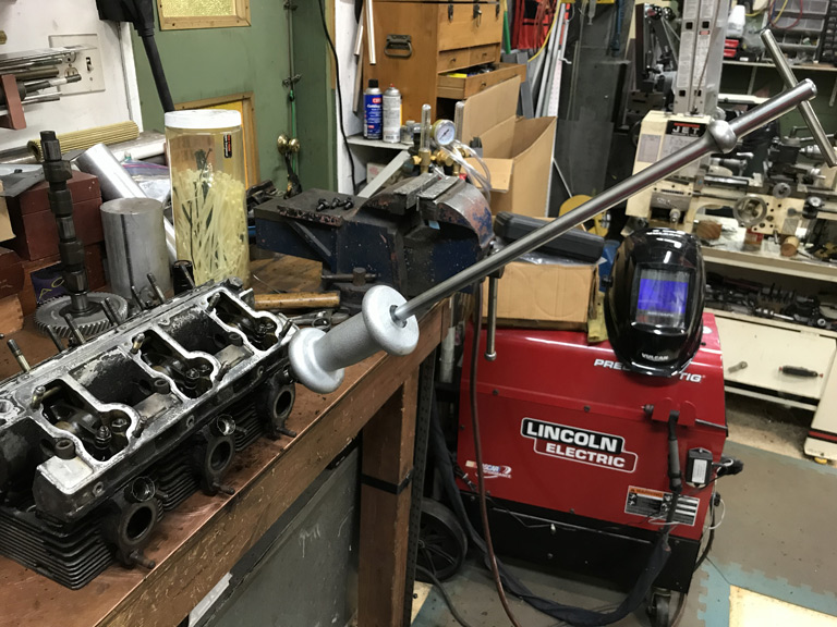
Here are the dimensions of the tool that worked for me just in case it can help someone else down the road. 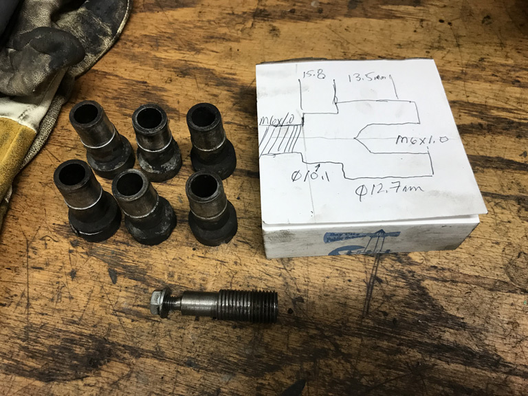
Head without the CIS injector cups. Now I need to start making plans to plug them! 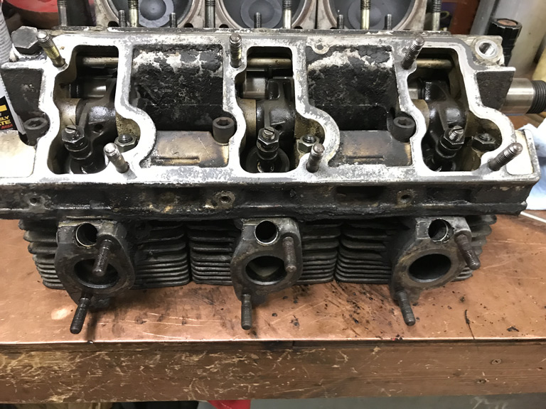
Posted by: Superhawk996 Oct 13 2019, 05:30 PM
Now for the loss of the day.
In the process of pulling the case studs in preparation for shipment to Ollies the upper engine mount boss cracked. I'll spare you the profanity that was uttered.
In taking a look at the broken off piece as well as the boss itself, I can see the boss had been cracked for some time. I just manged to finish the job. Magnesium is such a fickle material. The lightweight nature of it is awesome. The fact that it is prone to stress cracking over time . . . well, I guess you have to take the good with the bad. 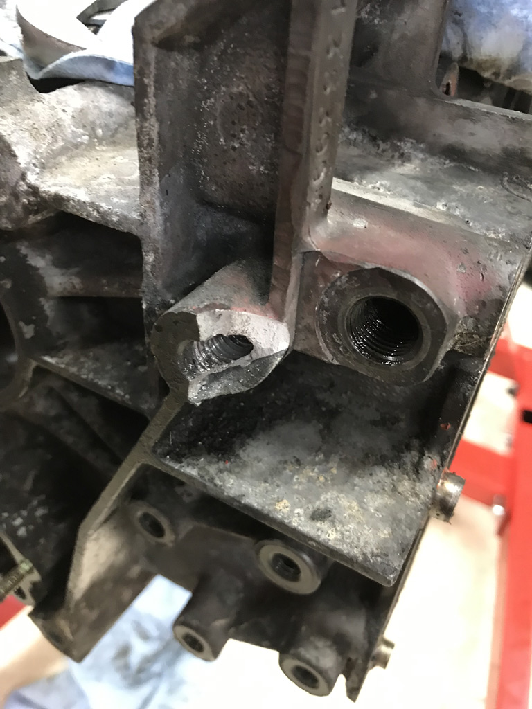
On the broken piece, notice the nice fresh white magnesium that cracked on the right side. Now look at the left. Dark and corroded. 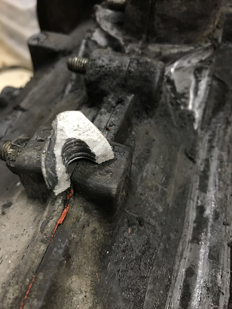
This was a pre-existing stress crack that had been propagating over time. It might be a good thing that it broke now, but, it sure doesn't feel that way. If it had broken after the case machining, I'd be absolutely screwed.
The way you can tell it was pre-existing is if you look closely at the dark section, you'll notice a characteristic "beach heading" sort of like the way water creates wavy patterns in the sand at the beach. This is a form of gradual crack propagation. Sort of a gradual erosion pattern over time. Then look at the white section. It's uniform, rough, and granular, sort of like a sugar cube surface. This is characteristic of the instant yield crack that coincided with the "snap" when it broke.
Usually I'm looking at these types of failure on parts at work. It hurts more to see it when my wallet is affected.
So off it goes to Ollies, they should be able to weld up the boss, building it back out and then doing a drill, tap, and facing on the boss. What a bummer. I've seen worse repaired. Luckily it will be buried under tin and between the engine and the firewall so I won't have to look at it.
The case got double boxed up, and it should go off for a final inspection and formal quotation request at some point this coming week. We'll see.
Posted by: porschetub Oct 14 2019, 11:40 PM
Looks like that case has been 'fretting" on the bearing saddles,that shows in the main bearing wear,lots of excess point loading due to the case being out of round.
Best to replace the case as the work to fix what you have isn't a good $$$ solution,go for a case half machining and a linebore to resize to std main bearings,you appear to have the skills to do the rest yourself.
Good luck.
@http://www.914world.com/bbs2/index.php?showuser=18995
Agree that there is some fretting of the bearings there but that really shouldn't be surprising on a high mileage (90K) case.
Problem is I REALLY want the 1973.5 7R case because it matches the vintage of my car. Machining the cases and a line bore back to standard is pretty much a given for these old Mag cases so I'll just roll with the punches and get it fixed properly.
Yes not an easy solution,its not like 2.4 cases are thick on the ground and the one you have numbers wise is rather like ''rocking horse shit'' to find.
Bugger you have had this bad luck,hope thinks improve some what for you,go well.
Hope to get the case boxed up and ready to ship today.
Posted by: Superhawk996 Nov 9 2019, 12:54 PM
Goodies arrived in the mail this week:
Ben fixed my cracked fan shroud for a mere fraction of what I was looking at to replace it with another used part. Welding mag just isn't on my bag of tricks.
Ben did a great job of not only welding the mag shroud, but he also clearanced the weld to allow the alternator to fit. I had assumed I'd have to take car of that myself. Thanks Ben! 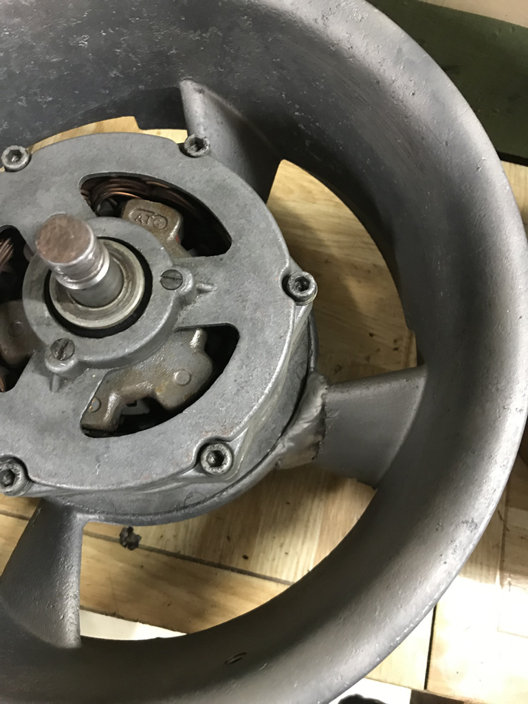
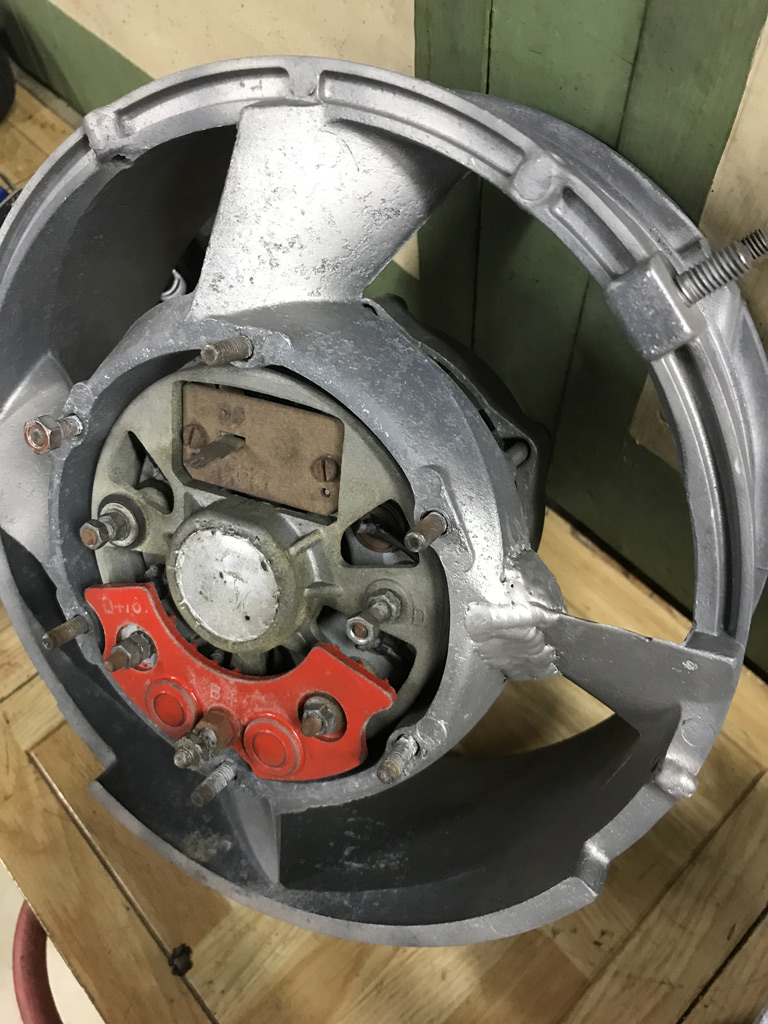
Now before anyone gets their panties in a wad about the size of the weld bead, keep in mind that none of this is easily visible with the fan installed.
I would much rather have the strength and extra material from the bead than trying to blend this back purely for cosmetic purposes. Even more so knowing that when this is actually installed in a 914 with the fan facing toward the rear bulkhead you can't see anything. 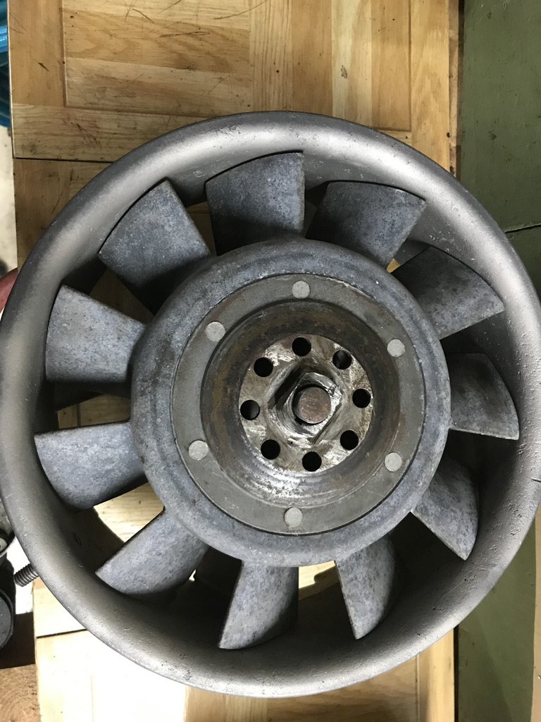
The fan spins perfectly with no contact to the welded shroud. No deformation of significance. Great job Ben!
To top that off, I purchased Ben's DIY oil tank kits. Looking forward to putting this little puzzle together! I did a quick bench top mock-up and the pieces are all nicely bent and look like they will fit up well with minimal tweaking. 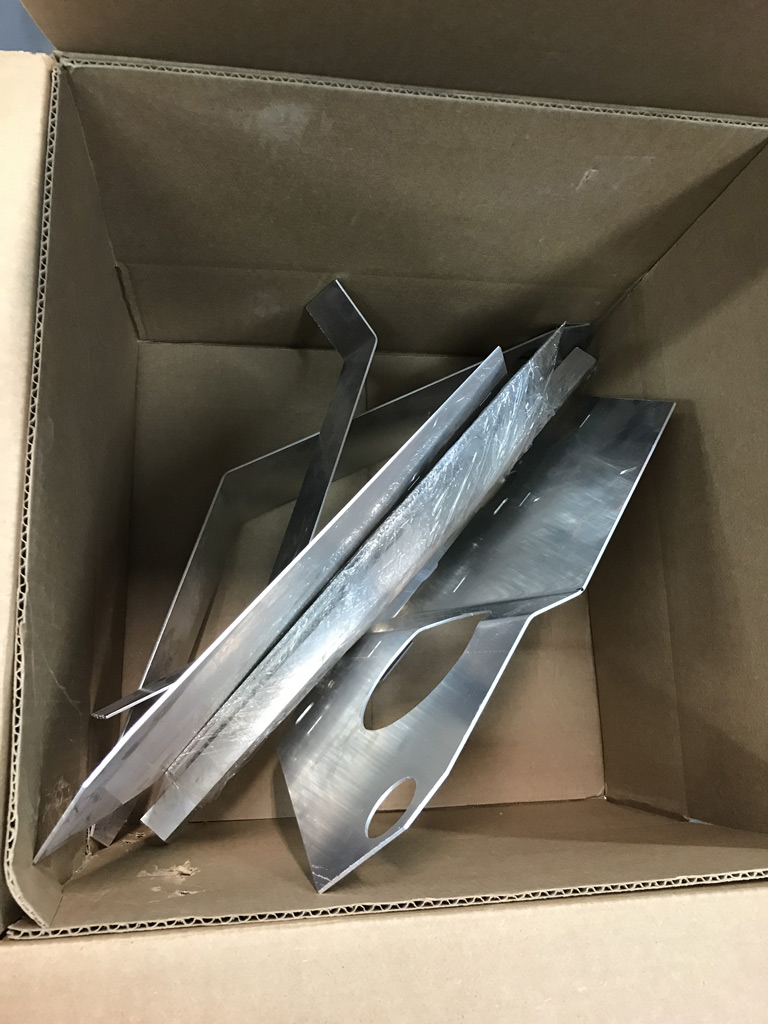
Hat's off to Ben!
Posted by: mb911 Nov 9 2019, 01:38 PM
Glad your happy with it.. The mag welding is always fun.. Porosity is nature of the beast..
I now have to decide on another run of oil tanks or not.
Posted by: mepstein Nov 9 2019, 02:30 PM
I’ll take mine welded. Thanks Ben.
Attached thumbnail(s)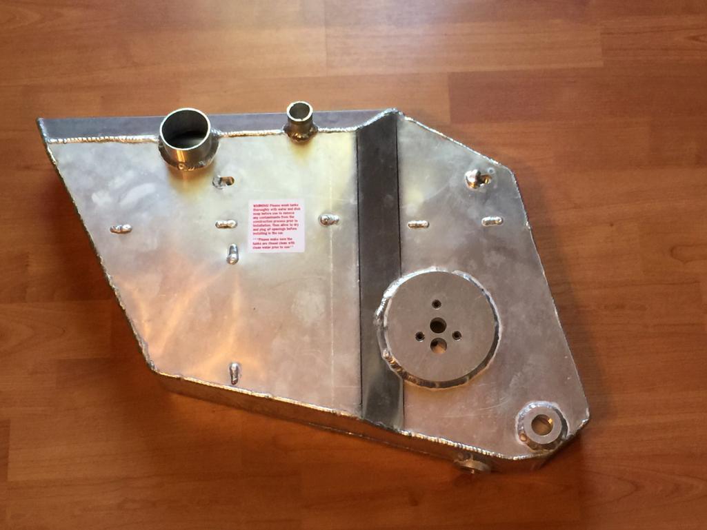
Posted by: porschetub Nov 9 2019, 03:15 PM
Excellent to see the fan housing repaired..many over on Pelican say it can't be done Ben has the skills,one thing I noticed with my housing was the importance of torqueing the mounting strap to spec,my fan had contact because I had done it up to tight,done up correctly the problem was sorted.
911 exhaust studs are bastard things ...1 third of mine were ok,the rest were too rusted @ the threads to reuse,heated and chilled them a few times and most came out,the rest I double nutted and welded the lower nut on,I let them cool and they came out.
I went for genuine replacement studs from Pelican and because I had heard conventional nuts loosen after a while I purchased a BMW 8mm "crush" exhaust nuts,they haven't required a retorque yet with my headers.
Good luck with your build.
Posted by: mepstein Nov 9 2019, 04:29 PM
Excellent to see the fan housing repaired..many over on Pelican say it can't be done Ben has the skills,one thing I noticed with my housing was the importance of torqueing the mounting strap to spec,my fan had contact because I had done it up to tight,done up correctly the problem was sorted.
911 exhaust studs are bastard things ...1 third of mine were ok,the rest were too rusted @ the threads to reuse,heated and chilled them a few times and most came out,the rest I double nutted and welded the lower nut on,I let them cool and they came out.
I went for genuine replacement studs from Pelican and because I had heard conventional nuts loosen after a while I purchased a BMW 8mm "crush" exhaust nuts,they haven't required a retorque yet with my headers.
Good luck with your build.
Ben’s been repairing fans and housing for years. He’s also done a 3.2 manifold and a 915 trans case for me. His welding credentials go way beyond small repairs but it’s nice to have his services available. Just wish he was closer so he could weld on my car.
Posted by: Superhawk996 Nov 9 2019, 04:47 PM
I couldn't be happier with Ben's work.
I'm still amazed at how many folks on forums will say that Magnesium can't be welded. I wish I had a proper welding shop, I'd give it a try buy there is just too much clutter in my garage should things go wrong.
I'll be taking next week off so I hope to get back to some welding on my chassis now that I'm pretty well healed up.
I also plan to go up to my father's house and retrieve a coupld of donor 901 transmissions that I stashed there about 20 years ago. They were stored off the ground, under a lean to, and with a vented tarp cover. Not sure anyting in them will be salvageable after 20 years but we'll see.
Posted by: Superhawk996 Nov 10 2019, 07:19 PM
Did a little measuring and it turns out that the bore used for the 911 engine 2.4L CIS injector cups are about 0.020" oversize to the standard drill that would be used for a 3/8 NPT tap.
This should be OK. Since a NPT thread form is a taper the oversize hole will result in two things:
1) the tapped thread will have slightly less than the standard thread engagement within the thread form.
2) the plug having to sit just a little deeper in the taperd thread to estalish a full seal.
So I went ahead a trial tapped one of the heads for a 3/8 NPT plug.
I'll go ahead and pick up a few Earls Aluminum NPT plugs and will make sure it fits and seals well before I do the others. 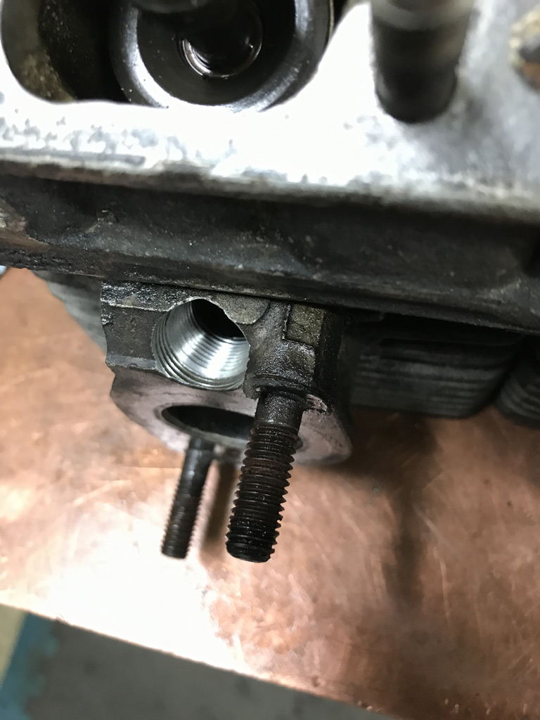
Posted by: Superhawk996 Nov 10 2019, 07:31 PM
I also did a little machine work on the GA004310 case that came with this car.
The first job was to drill out and Heli-Coil one of the M6 cheeseheads that was seized. This was straightforwad and drama free. Love when that happens. 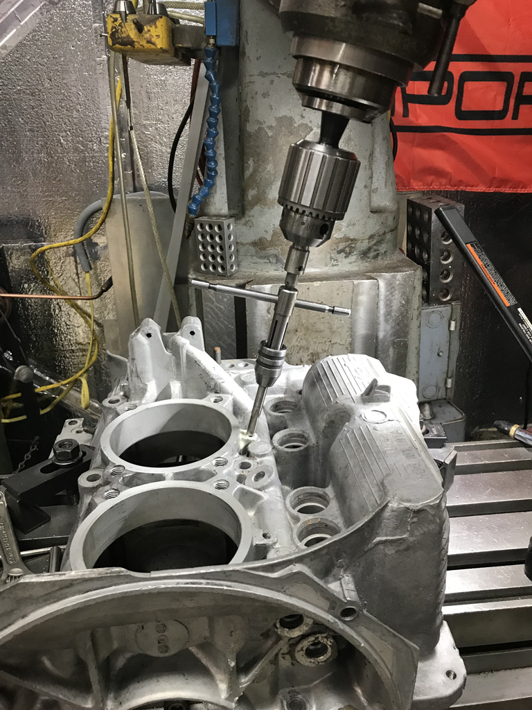
The other job is a bit of a head scratcher.
When I got this engine running it was leaking oil pretty badly from the oil pressure sensor. Somewhere in it's life, someone swapped the OEM pressure sensor and managed to strip it. Their hope was that lots of PTFE tape was going to seal it and that just wasn't the way it works. This car and this engine had such a rough life -- it is almost laughable if it weren't so sad. 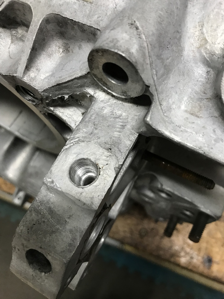
I had hoped that there would be enough material there to run the 1/8" NPT tap in a bit deeper and get enough thread to get a decent seal. As it turns out, that isn't going to happen either.
Although I was able to reestablish some thread, the tapped bottomed within the bore before I was able to create much new thread.
So now I think I have only two options
1) Weld the hole, drill, and retap. I don't see a good way to weld up this bore, it is pretty deep and I don't want to put a ton of heat into the area and end up having to remachine the oil cooler ports or something stupid.
2) Cut the bore oversize to 1/2", create a shrink fit aluminum plug, weld that around the top to ensure a leak free seal, then drill and tap a new NPT bore. I'm leaning toward this option.
Need to think about this overnight and see if I come up with a better plan before chips begin to fly tomorrow.
Anyone else ever repaired this oil pressure sensor thread area? How did you do it?
Posted by: gereed75 Nov 10 2019, 11:35 PM
This may not be a fix that meets your standard, but why not drill and thread for 1/4 NPT and put in a 1/4 x 1/8 adapter?
Posted by: Superhawk996 Nov 11 2019, 06:04 AM
This may not be a fix that meets your standard, but why not drill and thread for 1/4 NPT and put in a 1/4 x 1/8 adapter?
@http://www.914world.com/bbs2/index.php?showuser=15674
This is a really good suggestion. It speaks to why I felt the need to sleep on it before making chips. I need to do some closer measurement but I"m concerened about 3 things:
1) In side view of this area, there isn't a whole lot of meat there for anything other than a 1/8" NPT thread bore (see photo below of 1/4" adapter on top). The size of a 1/4" NPT is large enough that it is going to be a close call on thinning out the material too much. This also seriously limits how big I can make an aluminum plug.
In the case of a 1/8" NPT tap, the top of the taper is about 0.403" (major diameter). If I make a 1/2" plug, that only leaves 0.097" of diameter and 0.0485" (just over 1mm) of wall thickness (worst case @ full tap depth which won't happen) once I re-tap the machined the welded in plug. That really isn't much wall thickness after re-tapping. I wouldn't worry about it in steel but obviously we're dealing with aluminum here. Might not be so bad since I would never go full depth on the NPT tap.
Here is a quick sketch (Not to Scale) of what's being considered for an aluminum plug.
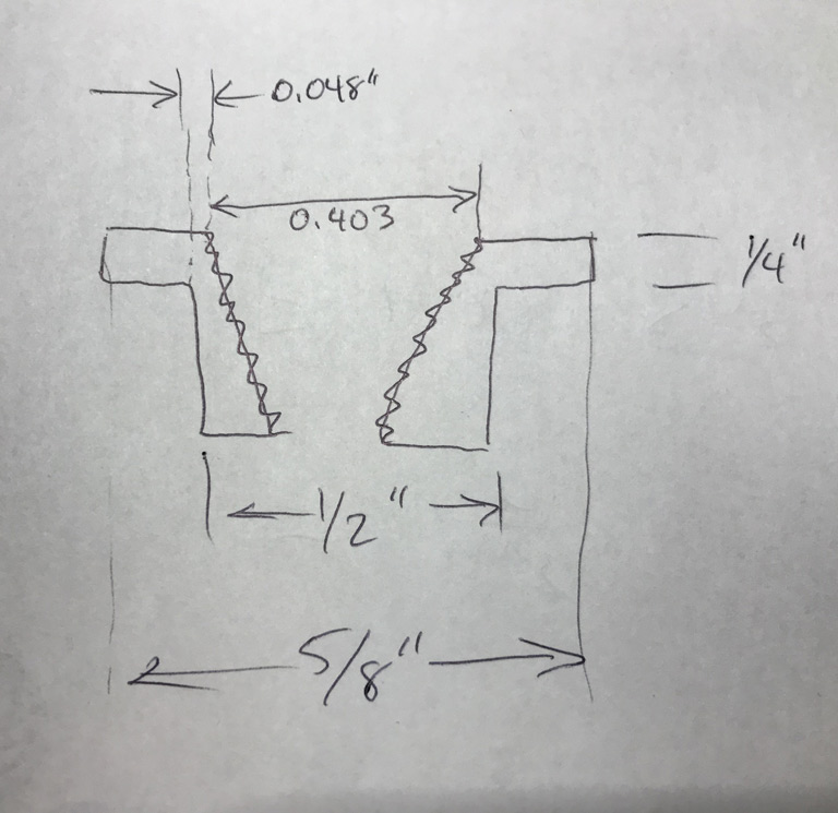
2) the added height of a 1/4" to 1/8" NPT addapter won't fit under the engine tin nicely. Likewise, it could be difficult to service later on with the tin installed. All my tin is out to powder coat - so I don't have tin to check this.
3) In general, the threaded in 1/4" to 1/8" adapter adds another potential leak path.
Here's the situation from the side view.
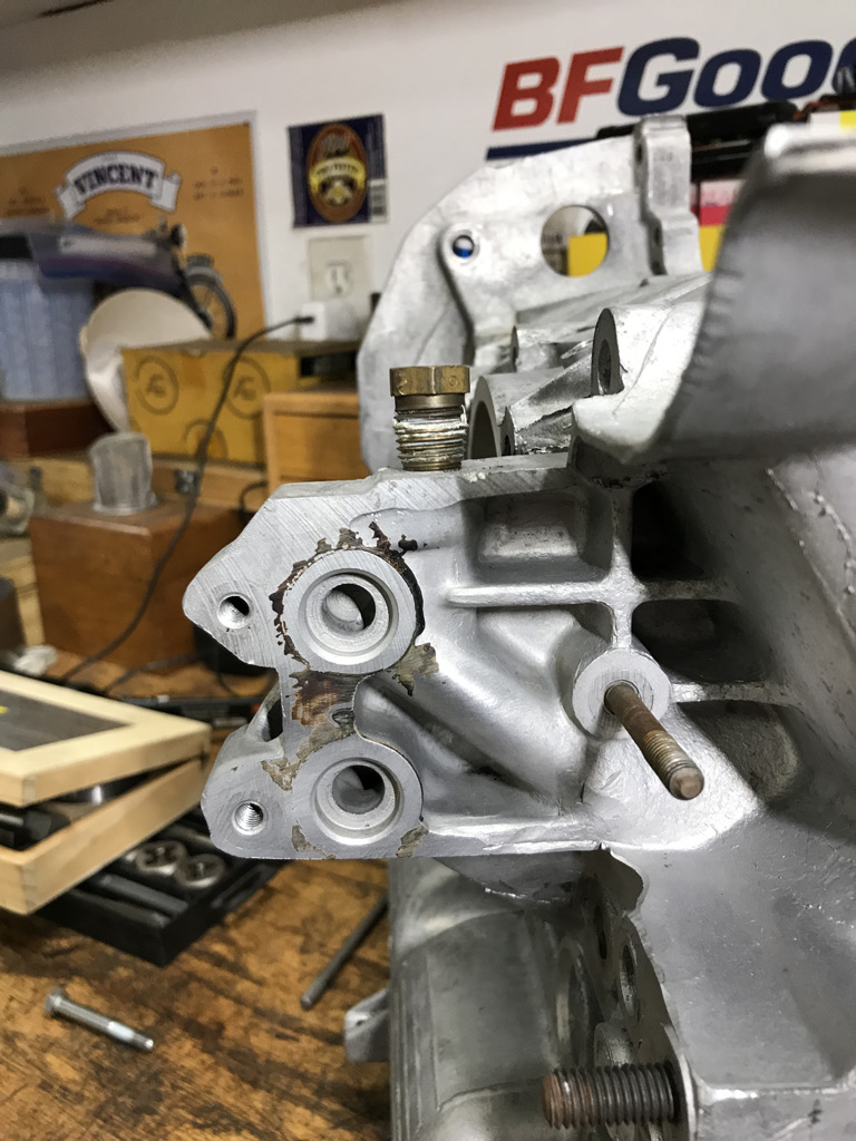
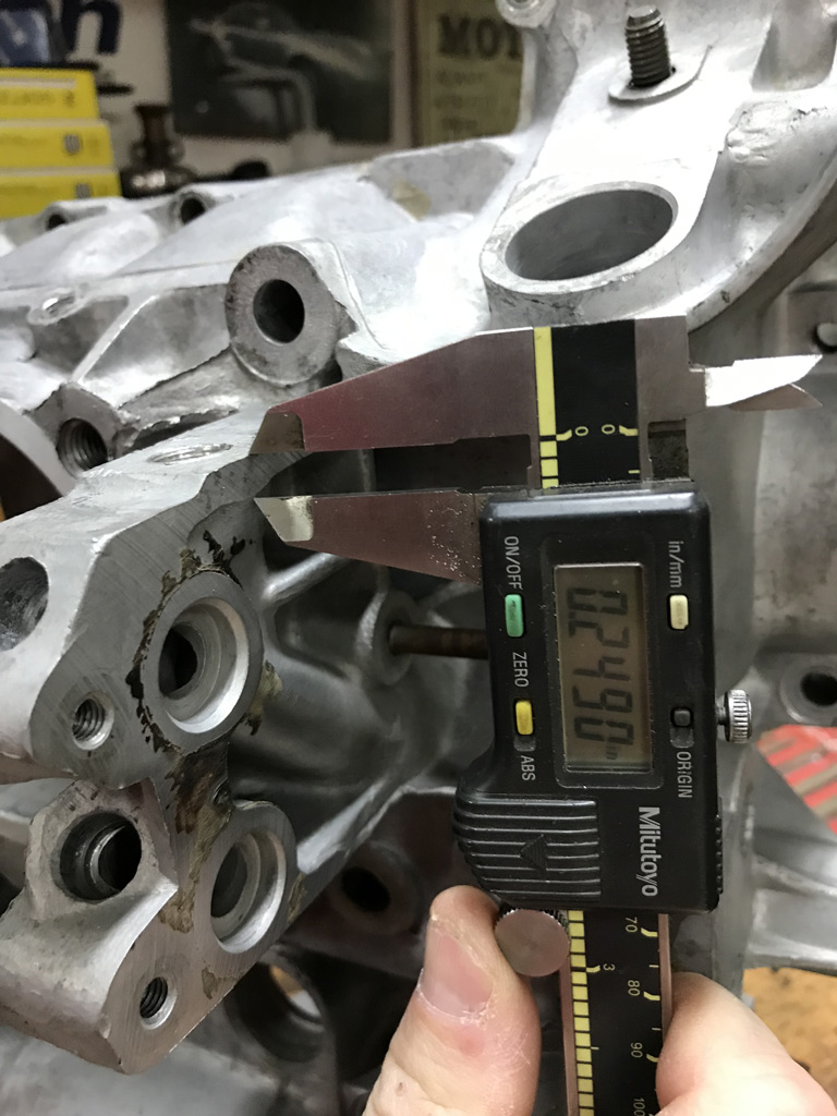
Posted by: Superhawk996 Nov 11 2019, 06:27 AM
I've also considering 1/8" NPT Heli-coils or Time-Sert now that I've thought about this a bit more after a good nights sleep.
The main issue is that the NPT Heli-coil uses a 3/8" drill. A 3/8 drill is already a loose fit to this hole. Having an oversize hole on a Heli-coil bore seems like a near certain leak path.
The other issue is a 1/8" NPT Heli-coil kit runs from $80-100. I don't see myself ever needing to use it again in my lifetime so it becomes a pretty large cost for a one use solution, that might still end up leaking.
A 1/8" NPT Time-Sert looks more appealing since the drill size is 13/32 (0.406") and this will be just barely large enough to clear out the stripped threads. I trust a Time-Sert to seal better than a Heli-coil if installed with some Loctite. About the same cost as the Heli-coil kit. Hmm.
Posted by: Superhawk996 Nov 11 2019, 07:38 PM
I pulled the trigger on fabrication of a ferrule to fix the stripped pressure sensor port. It just seemed like the right thing to do. It will be a solid fix that won't leak and there is no extra cost for one time use Time-Sert's (just my time), and there is no need to wait for Time-Serts to arrive. I wanted to keep this machine work moving forward.
After some measurement and a bit of a rethink on the dimensions I decided to only cut the lower bore to 7/16". The upper counterbore is 5/8". The upper 5/8" segment is 0.375" in length and the lower 7/16 segment is 0.25" in length. The bore in the case was cut on-size and the ferrule was built 0.002" oversize for a shink fit.
Here's a little video of the work to find the center line of the pressure port bore.
https://www.youtube.com/watch?v=FtXTVeNxI7w
Reamed the lower bore for a nice smooth finish. 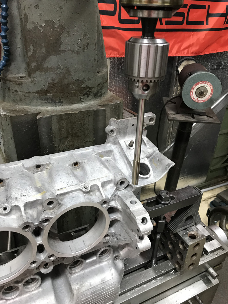
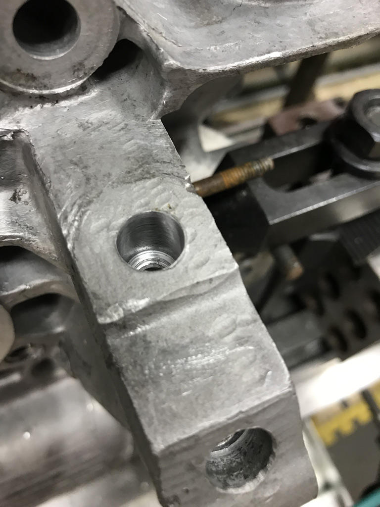
Then the 5/8" counterbore was cut 0.25" deep. 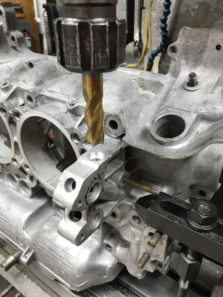
Then it was time to make the ferrule. 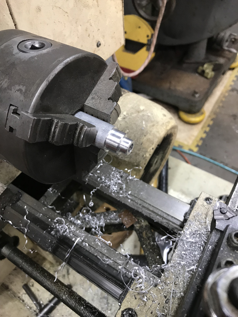
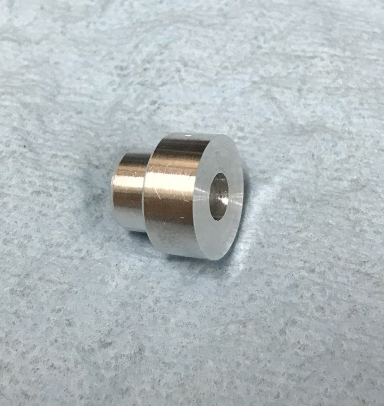
Put the ferrule in the freezer for about 1/2 hour, then heated the case with a rosebud oxy-acetylene torch and then tapped the ferrule home. 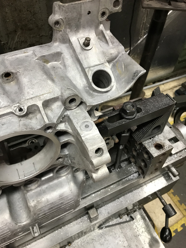
You'll notice I made the ferrule so that it stands proud of the surface by about 1/8" to give me something to weld to. It also gives me more material for the taper. The OEM Oil pressure sensor only theads in about 1/4" so having a 3/8" long section that is 5/8" diameter will give me plenty of material to tap into without thining the wall of the 7/16" diameter lower section. Once I have the port tapped to 1/8" NPT, I'll surface the top of the ferrule again for a nice flat surface.
And for good measure I welded the top 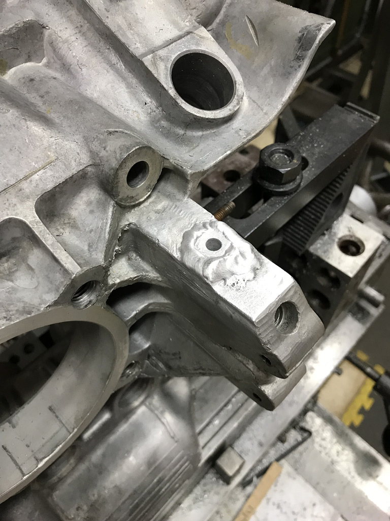
Drilled, tapped to 1/8" NPT and milled the top once things cooled back to room temperature. 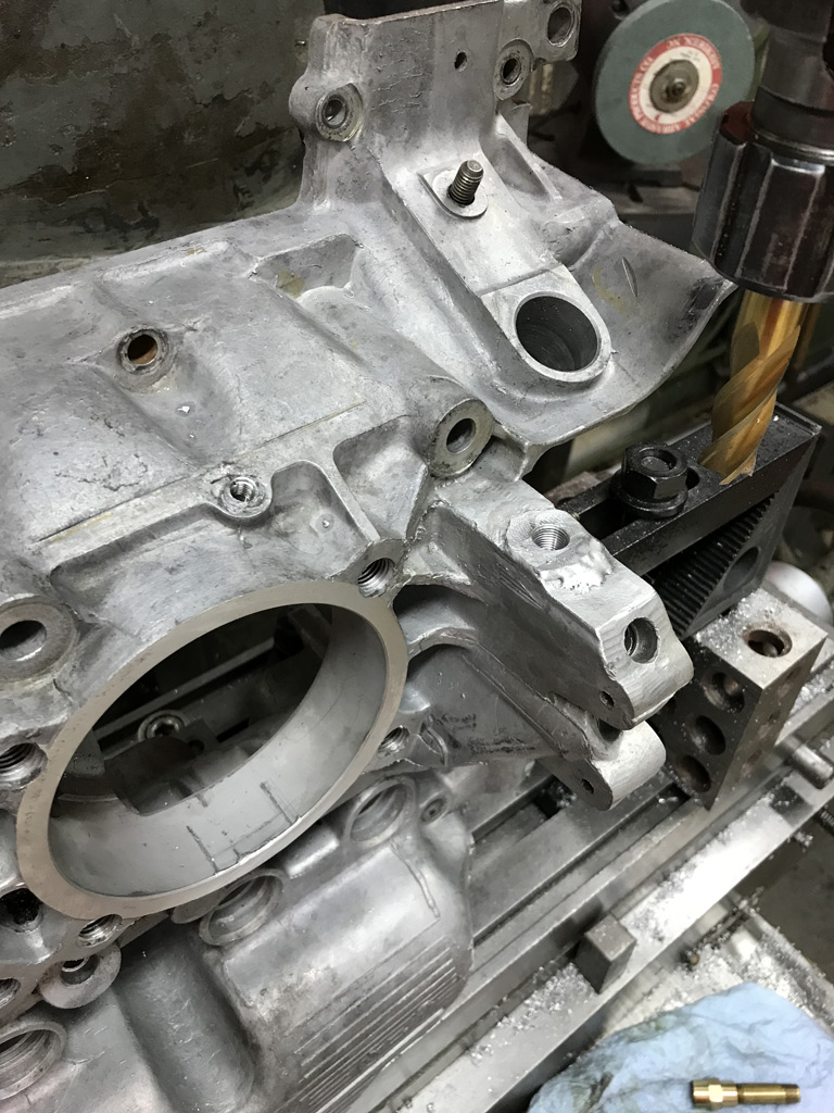
And finally, this critical machining project is finished. 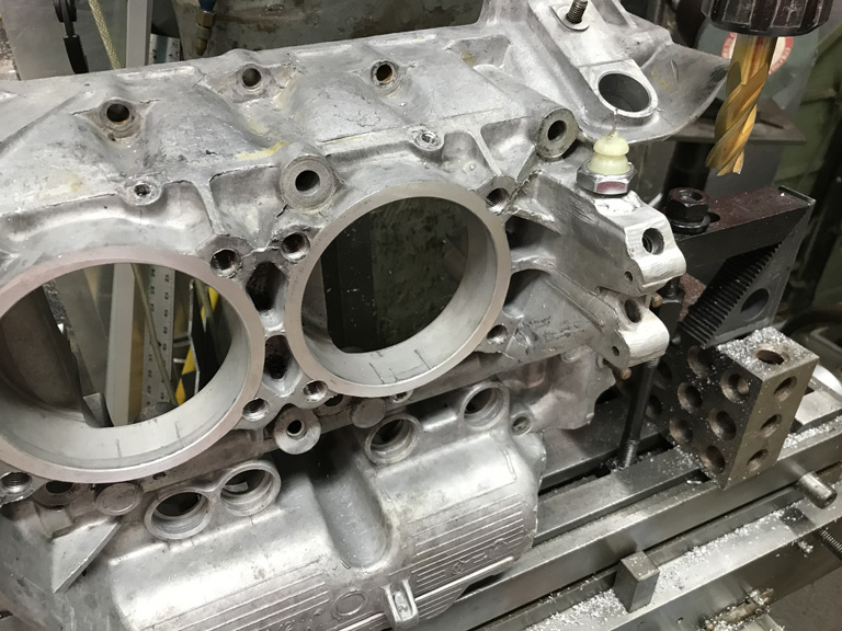
Posted by: Superhawk996 Nov 14 2019, 08:13 AM
Sorry to be jumping back and forth between the Type 4 GA004310 build and the teardown work for the 2.4L 911 engine but unfortunately this is the way I'm having to work at the moment.
Needed to get the 911 heads torn down and off my bench to free up space and to get them ready to be shipped to Ollies. 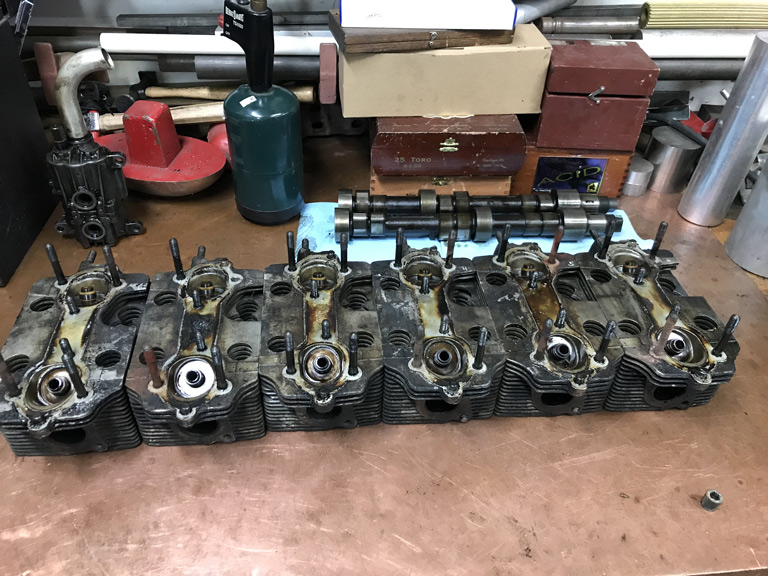
During the tear down I thought I find nearly all the valves to be bent based on the witness marks in the pistons. As it turns out only the #6 cylinder exhaust valve is bent to the point that it can easily be seen visually.
https://www.youtube.com/watch?v=x_P2JQpI5S8
Curiously, the #6 intake valve retainer was also cracked. 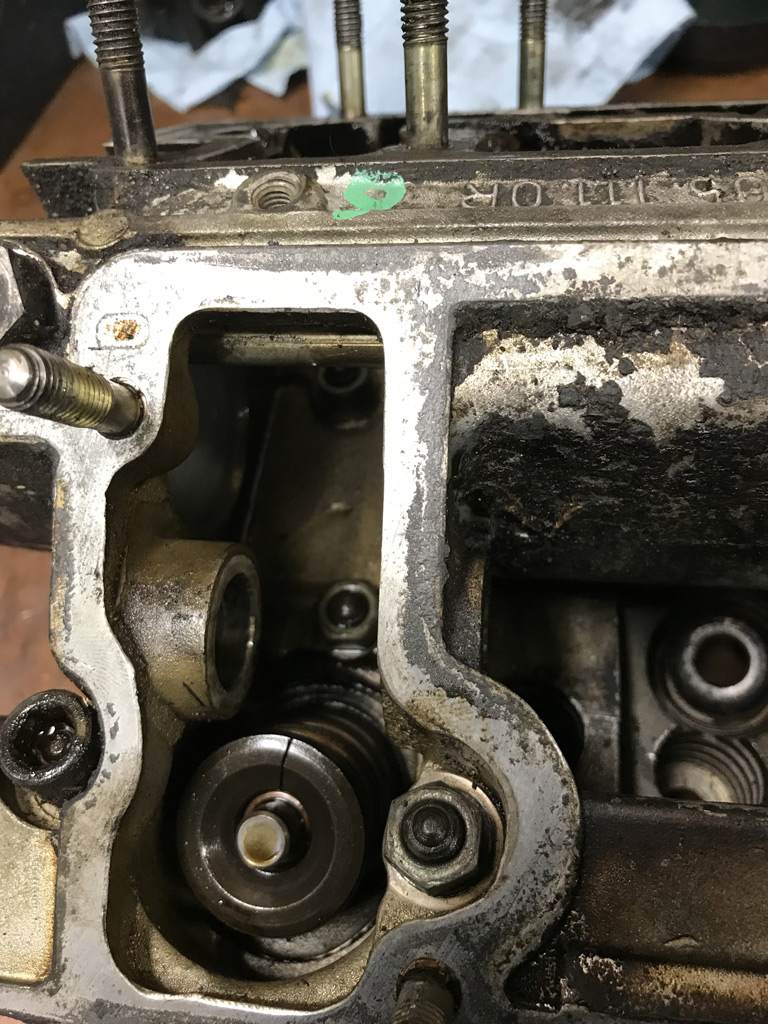
All the other exhaust valves had some pretty excessive carbon and light corrosion around the seat area but didn't seem to be terribly torn up to account for why I was getting such high leakdown off the exhuast valves.
I may chuck up the #4, and #5 valves today out of curiosity and put a dial indicator on them. However, it is a moot point. Since #6 is clearly bent, I'll reaplace all valves, springs, retainers, and keepers.
At this point I'm still not exactly sure what happened to this engine but I'm going to lean towards it having been over rev'd to the point that valves kissed pistons and cracked the #6 intake valve retainer.
Posted by: Superhawk996 Nov 14 2019, 10:17 AM
Looks like the 3/8" NPT plugs are going to be a workable solution for plugging the CIS injector ports.
Might need to think about making plugs later that can completely fill the old CIS bore so that I don't have a flow interruption where the old CIS port merges with the intake port but at this point, I think that is over-thinking it.
I can make custom port plugs later on if it becomes necessary to improve airflow and/or to keep fuel better atomized. The only real way to answer that is on a flow bench.
I suspect it isn't much of an issue given that the orginal 2.4L MFI 911E made 160HP with a similar flow interruption in the intake port area. The 911S was good for 190HP but did have larger valves and larger intake ports but the MFI still would have had an interruption in the intake port for the MFI injectors. 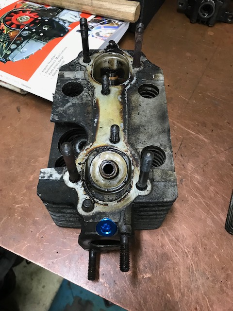
Posted by: kroelofsen Nov 14 2019, 11:33 AM
That is realy nice work! With the right machinery things become much easier...
Posted by: Superhawk996 Nov 14 2019, 12:39 PM
That is realy nice work! With the right machinery things become much easier...Indeed. However, believe it or not, I didn't have to do any machine work on the CIS injector ports. The CIS hole was very close (slightly oversize) to the size needed for a 3/8 NPT tap. I just got lucky on that one!
For anyone that thinks you need all the fancy tools, I can tell you I did my 1st car's restoration with not much more than a basic socket set, a pair of vice grips, a couple of adjustable wrenches, and a ball peen hammer.
I only bought an air compressor right before I did the paint work and at that point in my life, the compressor amounted to 1/2 month of pay!
I also distinctly remember deciding about 30 years ago at that point in time that I had to find a better paying career that would allow me to play with cars full time and would afford me the opportunity to have nicer tools. I eventually became an automotive engineer. I'd say it all worked OK.
Posted by: Superhawk996 Nov 14 2019, 12:55 PM
Given that I've had the sickness for about 30 years why stop now. I've been on vacation this week and mostly trying to catch up on neglected errands, and spending time with family.
Yesterday while visiting my father, I decided to retrieve a couple of transmissions that I've had in storage with him for about the last 24 years.
Total on hand - 4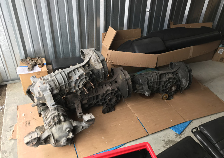
One that came with this car, one came with engine GA000099, and now these two on hand. 3 are side shifters and somehow I have a tailshifter even though I've always had 73's. I must have bought it ages ago for parts
I should now have plenty of donor parts to put together at least one really solid transmission. Won't know until I get inside them though.
@Dr Evil
A while back I purchased a Dr. Evil trans rebuild DVD to get a different perspective on how to properly rebuild these even though I've done a couple in the pre-internet era. Highly entertaining DVD's. Every now and again there is a comment in there that he just slips in that is hilarious. The best part might have been the labeling on the disks. 
Posted by: Superhawk996 Nov 24 2019, 04:01 PM
2.4L case, rods, and heads are now off to Ollies. Now its just a waiting game until they can do the work and wait for the bill.
Looking forward to the holiday weekend to get some quality garage time in. Neck is healed, pinched nerve is finally under control courtesy of Advil. Should be able to do some chassis work this coming long weekend.
In anticipation of that, I've just been continuing to gather parts. 5 lug conversion plan is starting to come together courtesy of Garold and Larmo! 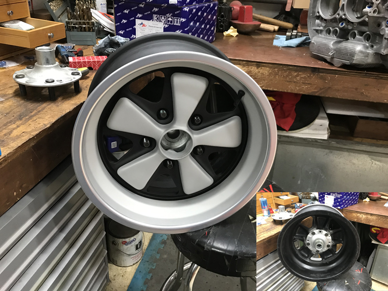
Posted by: Superhawk996 Nov 24 2019, 04:15 PM
The negative cash flow from the 914 is bad enough but I've also come to realize a new problem.
With the 914 tying up the garage, I don't have anywhere to work on the rest of the fleet. The choice is either work on them out in the open or pay someone else to do the dirty work.
My Jeep has penchant for developing dragging front calipers that need to be replaced every 4 years or so. With winter coming it was time to get that taken care of so I have a snow vehicle. Simultaneously, while commuting to work last week, the Mazda MPV parts hauler decided to spit out the #1 spark plug. I purchased the MPV used last fall for dirt cheap. It served me well so far by picking up two engines and hauling parts to/from storage, but, apparently somewhere in it's past, someone stripped the spark plug threads and it finally let loose.
My wife now realizes just how much my labor is worth. $1000 bill to repair the two of them in the same week! That sucks! I really hate paying others to do what I can for myself! Next time, I may just have to do it in the driveway!
Posted by: porschetub Nov 24 2019, 04:35 PM
Really impressed with your machine skills I have that but no gear to do it on ,up until recently I had use of a mill and lathe ,when I was a chief engineer on ships I had all this to work with in my spare time and sometimes when I was on "watch" on easy days,miss that part of the job.
Lots of stuff for folks to learn from your thread ,keep it up  .
.
Posted by: Superhawk996 Nov 24 2019, 07:09 PM
Really impressed with your machine skills I have that but no gear to do it on ,up until recently I had use of a mill and lathe ,when I was a chief engineer on ships I had all this to work with in my spare time and sometimes when I was on "watch" on easy days,miss that part of the job.
Lots of stuff for folks to learn from your thread ,keep it up
.@http://www.914world.com/bbs2/index.php?showuser=18995
Chief engineer on ships sounds like an ultra cool job. Ton's of cool machinery on a ship!
Posted by: Superhawk996 Nov 24 2019, 07:15 PM
One minor project completed today between Honey-Do projects of planting fall bulbs & yard chores.
Cleaned up one of the 2.4L cam tower housings. I don't have a lot of confidence in handing these off to my local machine shop for hot tanking. The surface finish between the heads and the cam tower housing is a very fine, almost lapped surface finish that doesn't rely on a gasket between the heads and the cam tower.
I'm a bit afraid that someone will end up banging parts on wire racks and/or metal benches. Plus, evertime I get parts back from the tank I still end up having to do a good hand scrub to get to my standard for cleanliness.
Used one of my favorite cleaners for motorcycles. S100 is the product name. It does a good job of breaking down grease deposits and then rinsing away clean. Still a lot of work involved with various brushes to get into the nooks but it turned out pretty well for about an hour and a half worth of work. Good enough for now. Will do final cleanup when engine is closer to assembly.
Attached image(s)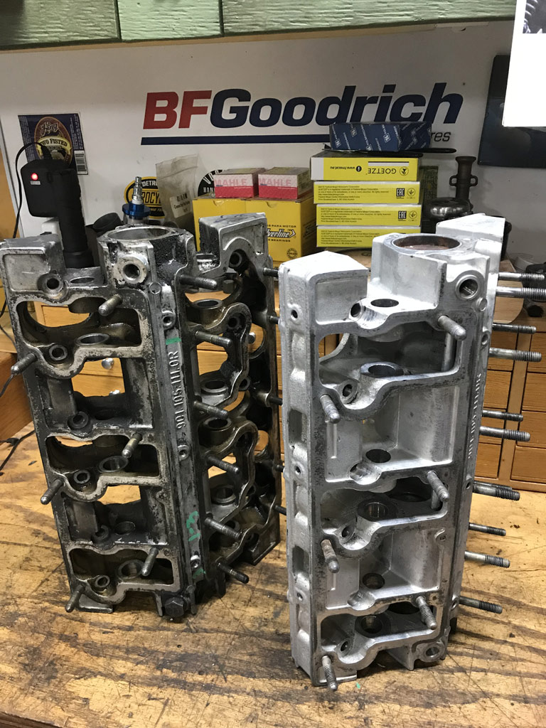
Posted by: eatpez Nov 25 2019, 11:27 AM
I love this thread and love the fact that you are also local to me. Inspires me to update my thread and continue the body work on my chassis, although the recent spell of really cold weather makes that more difficult without a properly heated garage.
If you ever need a second pair of hands, don't hesitate to send me a PM.
Posted by: Superhawk996 Nov 25 2019, 06:59 PM
@http://www.914world.com/bbs2/index.php?showuser=22543
Reddy Heater 55000 BTU kerosene heater has been my only heat for 20+ years.
Over the years I’ve added insulation. I just insulated my 1960’s vintage metal garage doors last year. Should have done that a decade ago. Don’t need fancy heat. Sure would be nice though!
I dream of building my dream pole barn with a lift and radiant floor heat .. . Maybe someday! 
Start basic. Don't let perfect be the enemy of good enough!
Brent Brock Has done amazing work out of a Harbor Freight temporary carport. I think Jeff Hail had a saying in his post to the effect of be the Spirit Of Can! Channel it. Don’t let obstacles stop you! Not even the crap we call winter.
Posted by: bbrock Nov 25 2019, 11:06 PM
Brent Brock Has done amazing work out of a Harbor Freight temporary carport.
Full disclosure though. The tent was in addition to a radiant floor heated (albeit cramped) garage. And I complain frequently. Kudos to you for soldiering on without central heat. I do envy your toys though. Posted by: Superhawk996 Nov 29 2019, 03:23 PM
Well another win some lose some day.
Picked up engine tin from Powder Coat. Overall I'm very happy with how it turned out even if it did take extraordinarily long. 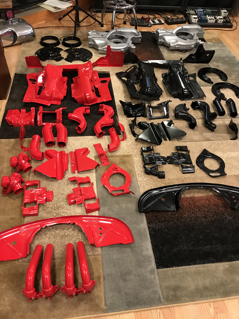
The red was done in gloss and the black in satin.
I'm pretty happy how the repairs turned out. I wasn't sure how much coverage I'd get with the powder coat. Overall, I'm happy but I can see a little of the weld seam in the engine tin I had to fabricate to reair the A/C butchery. 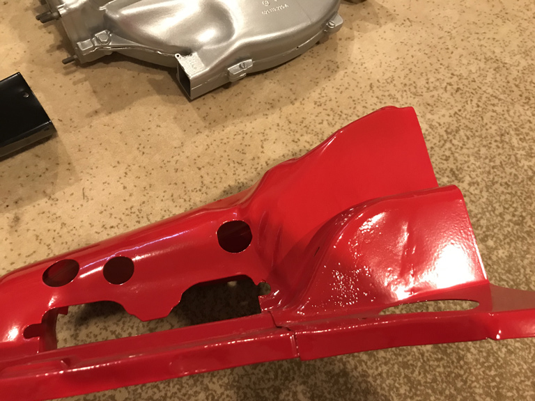
The Black Satin definately hides better than the gloss. Here is the tin that had the crack repair under the coil. 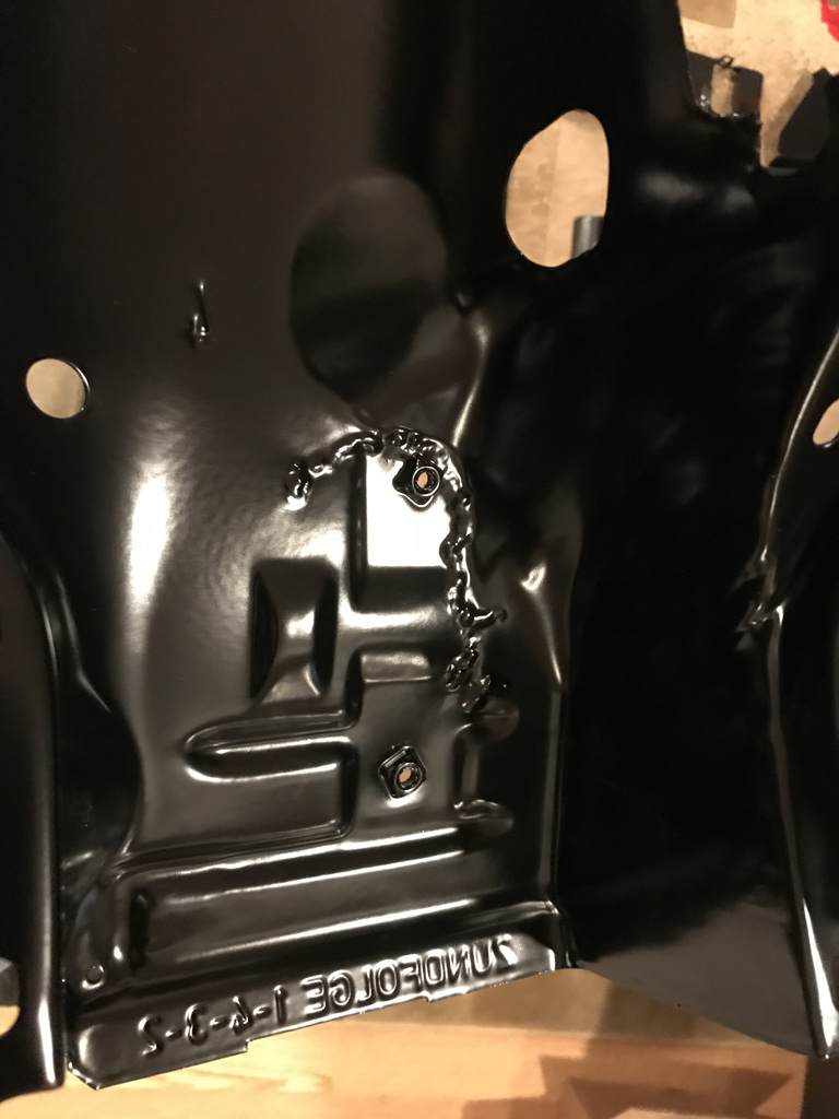
and the top side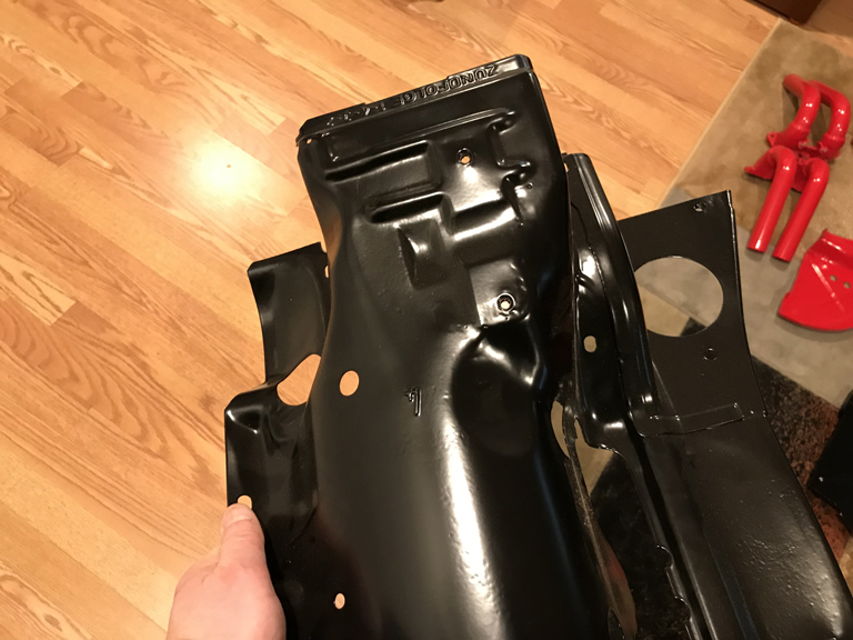
And of course there is always one little oopsie the you don't see coming. Looks like I missed a rust spot. When the tin was sandblasted it looks like it blew out and of course the powder coater just chugged along. 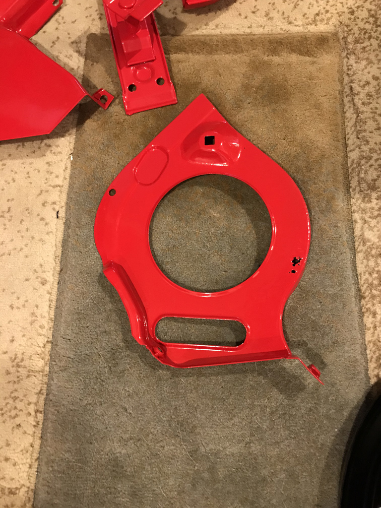
Oh well. At least this isn't on a visible area. I may just epoxy it a bit . . . or I may try to find another piece and have it powder coated seperately. We'll see.
Posted by: mepstein Nov 29 2019, 03:32 PM
I've often found rust holes after the fact when doing engine tin. That's one of the reasons our shop won't do outside parts for a fee. Too many little gotchas that can triple the time you can charge for.
Posted by: Superhawk996 Nov 29 2019, 03:44 PM
I've often found rust holes after the fact when doing engine tin. That's one of the reasons our shop won't do outside parts for a fee. Too many little gotchas that can triple the time you can charge for.
@http://www.914world.com/bbs2/index.php?showuser=10825
It all went pretty well on the whole. Only once piece out of many, so, no worries.
I spent a lot of time welding cracks and straightening before I sent it out. Speaks more to my lack of quality control than the powder coater's. He probably didn't even see it when suited up in the blast booth and depending on the lighting, may not even have seen it when applying the powder.
Doing retail repair work is definately a risk. Sort of explains why so many shops (not just yours) don't do outside work anymore. I worked retail in college. You get some dicey characters!
Posted by: Superhawk996 Dec 7 2019, 08:10 PM
Due to holiday's and work it seems like I haven't been making much progress. Last weekend was largely sent with the remnants of the 2.4L CIS & intake system tying to first get it taken apart so it fits in smaller boxes and then to determine what is salvageable.
Today, I spent a little time today messing with Ben's DIY oil tank kit.
Fit up and laser cutting are top notch. Unfortunately my welding technique doesn't quite lend itself to the nice, neat, uniform stack of dimes look. Functional -- yes. Pretty -- No.
Maybe someday.
Anyway, here are a couple quick pictures of the work so far. 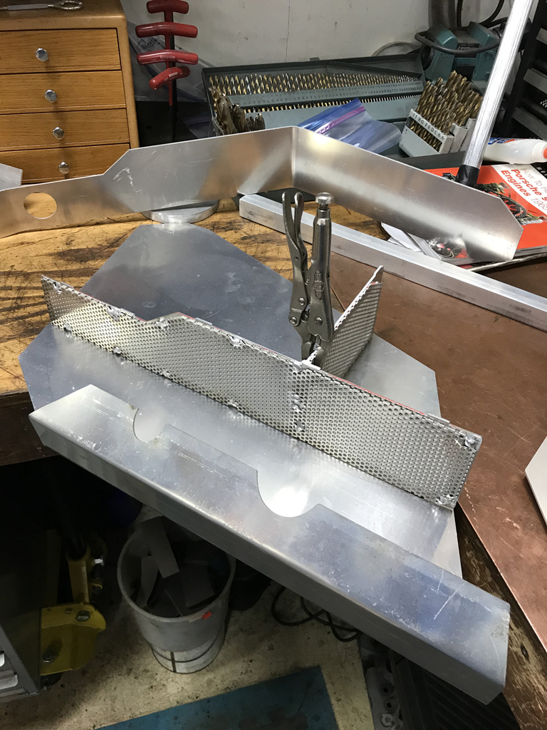
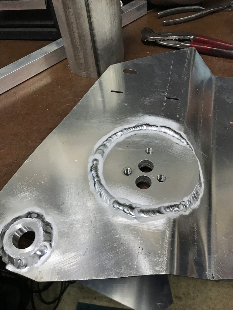
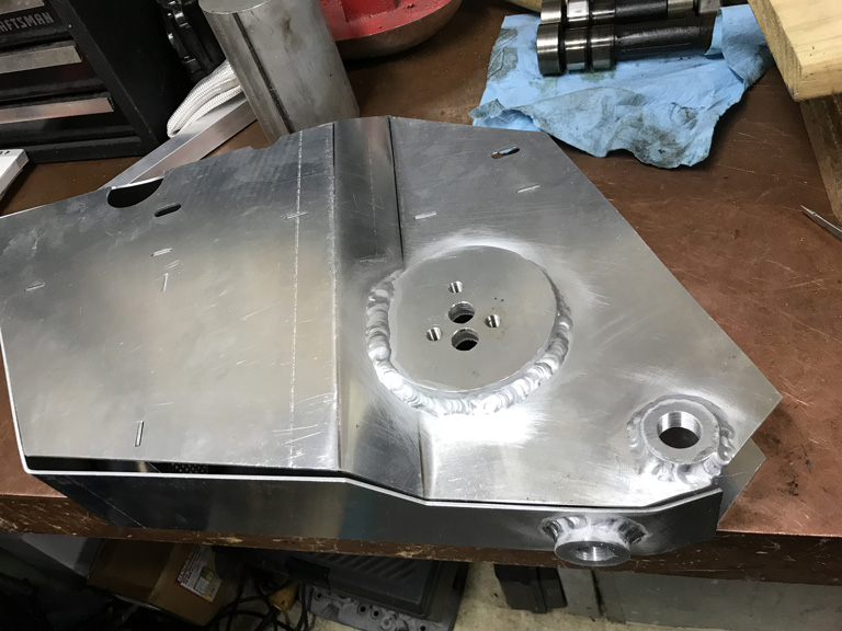
Posted by: mb911 Dec 7 2019, 09:06 PM
@http://www.914world.com/bbs2/index.php?showuser=22428
The top baffle needs 2 holes in it.. 1 for the filtered return oil to remove air from the oil and the. One for the oil filler neck/dipstick area..
Posted by: Superhawk996 Dec 8 2019, 09:03 AM
@http://www.914world.com/bbs2/index.php?showuser=22428
The top baffle needs 2 holes in it.. 1 for the filtered return oil to remove air from the oil and the. One for the oil filler neck/dipstick area..
@http://www.914world.com/bbs2/index.php?showuser=9892
Yup. Waiting on that sweet Black Friday group buy of GT filler necks to arrive.
Easy to burn in the holes by blowing out the Aluminum screen with the TIG Electrode. Certainly appreciate the reminder though. I'm still playing with the best way to do the internal oil lines.
I think I also need to get an oil filter console in my hands before I do that. I'm tempted to do a light surface cut on the big console disk to make it perfectly flat. However, that needs to be done after all backside welding is complete otherwise the welding will warp the flatness of the disk when I weld on the back side return lines.
I'd rather do that machine work before I have a fully assembled tank.
Probably overthinking this since I'm betting your intent was that this could be assembled without the need for any machine work under the assumption that the console 0-ring will accomodate any minor unflatness.
Posted by: mb911 Dec 8 2019, 09:56 AM
@http://www.914world.com/bbs2/index.php?showuser=22428
The top baffle needs 2 holes in it.. 1 for the filtered return oil to remove air from the oil and the. One for the oil filler neck/dipstick area..
@http://www.914world.com/bbs2/index.php?showuser=9892
Yup. Waiting on that sweet Black Friday group buy of GT filler necks to arrive.
Easy to burn in the holes by blowing out the Aluminum screen with the TIG Electrode. Certainly appreciate the reminder though. I'm still playing with the best way to do the internal oil lines.
I think I also need to get an oil filter console in my hands before I do that. I'm tempted to do a light surface cut on the big console disk to make it perfectly flat. However, that needs to be done after all backside welding is complete otherwise the welding will warp the flatness of the disk when I weld on the back side return lines.
I'd rather do that machine work before I have a fully assembled tank.
Probably overthinking this since I'm betting your intent was that this could be assembled without the need for any machine work under the assumption that the console 0-ring will accomodate any minor unflatness.
Correct.. The o ring does a pretty good job of sealing..
Posted by: Superhawk996 Dec 8 2019, 10:06 AM
Correct.. The o ring does a pretty good job of sealing..
@http://www.914world.com/bbs2/index.php?showuser=9892
Thanks Ben, appreciate the oversight. You have some awesome products! I'm absolutely amazed at how little tweaking it took to get the console disk, and the fitting bungs to fit. The laser cutting is nearly spot on.
Part of my rationale for doing this as DIY in the first place is to get more seat time with the welder, it's the only way to improve my Aluminum welding consistency.
Posted by: mb911 Dec 8 2019, 11:37 AM
Correct.. The o ring does a pretty good job of sealing..
@http://www.914world.com/bbs2/index.php?showuser=9892
Thanks Ben, appreciate the oversight. You have some awesome products! I'm absolutely amazed at how little tweaking it took to get the console disk, and the fitting bungs to fit. The laser cutting is nearly spot on.
Part of my rationale for doing this as DIY in the first place is to get more seat time with the welder, it's the only way to improve my Aluminum welding consistency.
Practice makes perfect
Posted by: Superhawk996 Dec 8 2019, 09:48 PM
Shifted gears a little bit as I work to clean up the garage and get rid of parts that I've been tripping over for months.
Goal is to get ready to get back to doing chassis work.
I've had a chunk of donor sheetmetal sitting on the floor that will be needed to fix the driver side fender inner to floor pan area that is rusted out.
Here is the starting point. 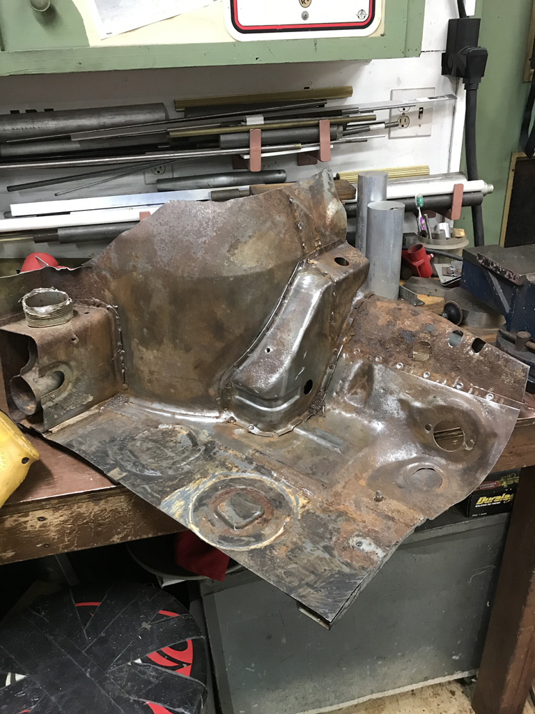
This piece of sheetmetal that holds the pedal boad is basically completely gone at the bottom on my car. This donor part is a good start but will still need some TLC to get it ready but it's better than trying to fabricate from scratch. 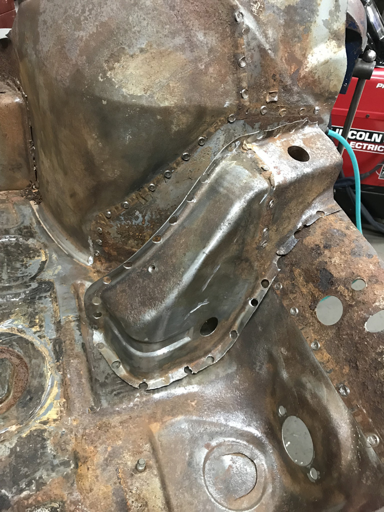
And here are all the parts discected. Much easier to store under a bench and out of my way for now. 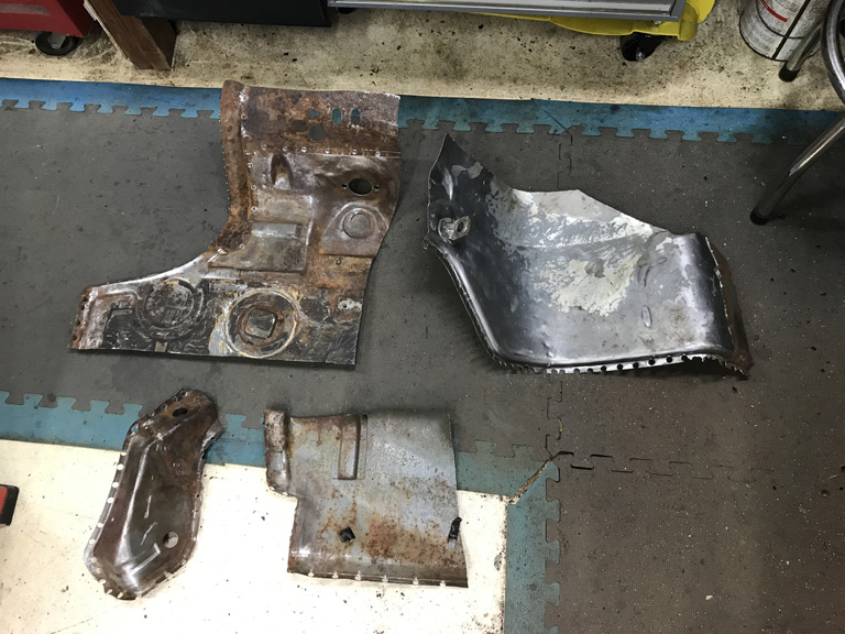
Posted by: tygaboy Dec 9 2019, 09:33 AM
Spot weld hell... I feel for you, brother.
Posted by: Superhawk996 Dec 13 2019, 06:49 PM
@http://www.914world.com/bbs2/index.php?showuser=9892
Ben, would you be able to post a picture of how you do your tank internals?
Did some more work today on the oil tank internals the plumbing to feed the filter was straight foraward. 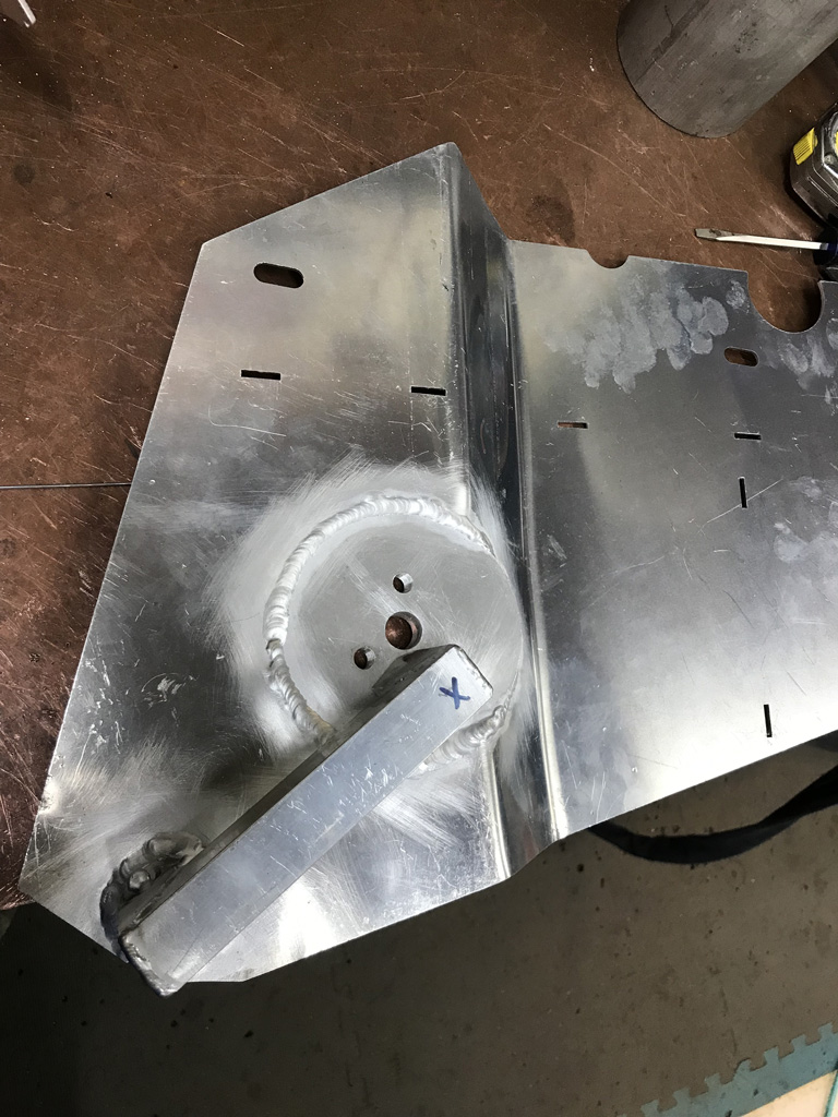
But since I don't have a GT filler neck in hand yet, I'm not sure which side the dip stick tube runs toward. Right, left, or maybe right down the center. The only picture i have of it is ambigious. 
I'd prefer to route the filterd oil outlet to the right side to get more time with the screens to deairate the oil. 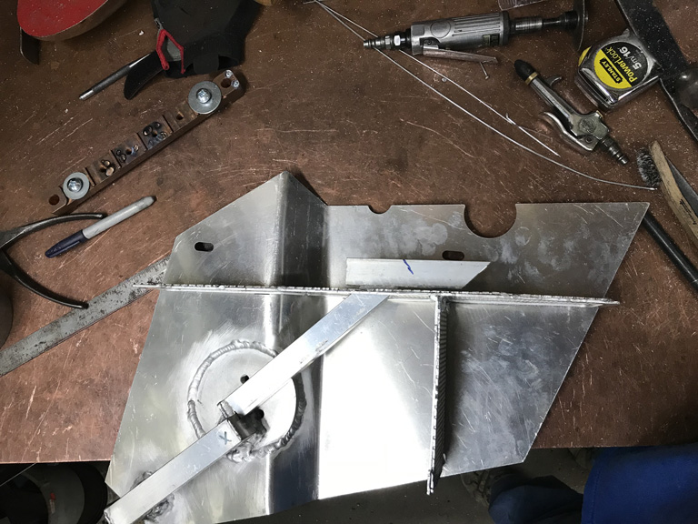
But I'm not sure if this routing will interfere with the dipstick tube.
The other option is to creat a U-turn back to the other side like the OEM tank but I'd rather not have to do this. 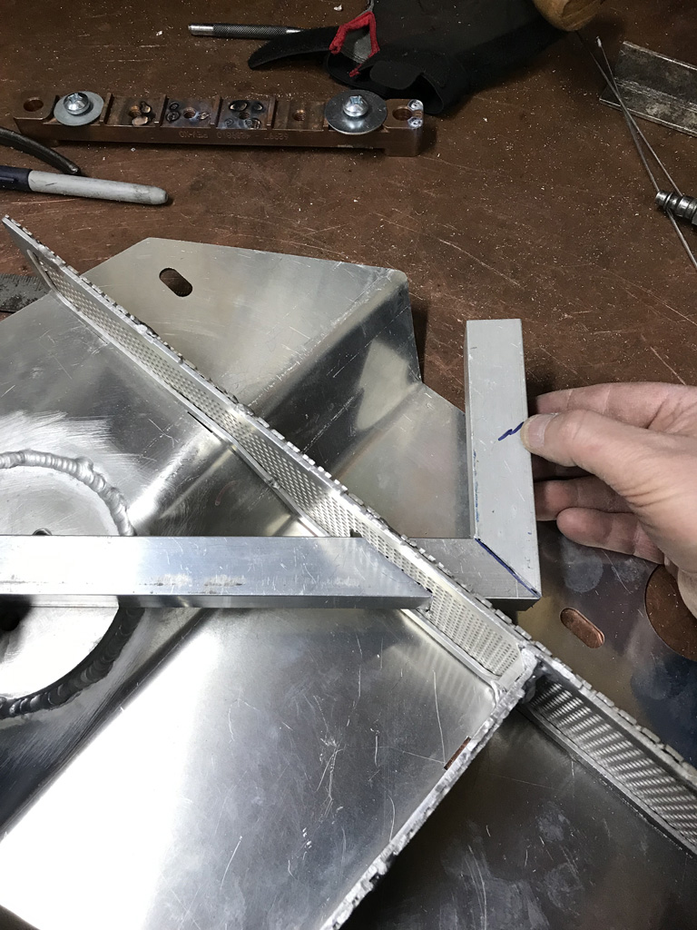
Any photos of your internals and/or a confirmation on which side the GT filler dipstick runs to would the awesome.
Posted by: mb911 Dec 13 2019, 07:14 PM
This is a super quick sketch..
Ps your filler came today.. 
Posted by: Superhawk996 Dec 13 2019, 07:23 PM
Perfect. Thank you Ben. Roughly aligns to what I wanted to do. I'll keep filtered oil exit closer to the vertical screen / baffle.
Posted by: sixnotfour Dec 14 2019, 01:12 AM
I dont know your 911 2.4 plan, but the 2.4 cis intake ports are tiny..Ollies gonna bore em out ??
Also as you did on the type 4sale case is what I do to the 2.4 cis inj. ports press in a shaft and weld the the top..when porting , smooth transition...lots of irons in the fire.. 
Posted by: mb911 Dec 14 2019, 09:20 AM
@http://www.914world.com/bbs2/index.php?showuser=22428
Make sure the mesh is at the exit of the bypass and extends 4-6 inches from there.. The idea is to remove the air bubbles from the oil.. Thats also the plan with the vertical baffle..
Ps I decided to make more tanks.. I just ordered more laser cuts..
Oh and pss.. I just hit my 4 year anniversary on my build..
Posted by: Tdskip Dec 14 2019, 09:38 AM
Thanks for the updates, great thread.
Posted by: Superhawk996 Dec 14 2019, 10:12 AM
the 2.4 cis intake ports are tiny..Ollies gonna bore em out ??
I don't see port size (or HP) as a measure of my manhood. I'm still deciding since 2.4L's are a bit of an odd bird. The valves are all 46mm/40mm for T, E, and S. The 2.4T heads have a 33mm exhaust port which is right between the E (32mm) and the S (36mm) so I'm not too worried about exhaust port size. The intake is a 30mm port which is 2mm smaller than most of the earlier heads at 32mm and about 36mm for the S variants.
Where it gets interesting is that a 2.4LT variant is 140 HP & 148.5 ft*lb of torque @ 4000. the 2.4L 911E is 165 HP@6200 & 151 lb*ft@4500 rpm.
So what is the take away? Remember the formula (RPM * T) / 5252=HP. So the only way the E has an advantage is that it makes about the same torque but up to higher RPM's.
The small 30mm intake port keeps flow velocity high which is a good thing at lower RPM's (i.e. good in town driveability). What it doesn't do is breath as well at the high RPM's but let's be honest, how often are you driving at 6200 RPM in a daily driver? When I had my Miata my daily goal was to hit redline (7200) at least once a day with it but it was only a short temporary burst here and there when accelerating. Never was able to drive there for extended periods of time.
I'm tempted to stay at 30mm in the short term and see how I like it. Since want to go to ITB's and modern FI I think some breathing capability will open up just by losing the long 2.4L CIS runners. But that will also degrade some of the low end torque as the runner length diminishes with ITB's. Or, it may lean in favor of more RPM but at lower torque which could end up being a wash. They can easily opened up at any time if I don't like them.
The bigger problem is PMO ITB's only have 34mm as their smallest port.
I see no need for 34mm ports with a 2.4L. From what I see online, I'm a bit worried that I'll have to do my own ITB's, modify PMO's, or maybe fabricate some sort of Plenum and runner system from the 2.4L CIS runners At this point Ollies hasn't even called to discuss so I'm still deciding.
Posted by: Superhawk996 Dec 14 2019, 10:33 AM
@http://www.914world.com/bbs2/index.php?showuser=22428
Ps I decided to make more tanks.. I just ordered more laser cuts..
For anyone cosidering Ben's tanks, his welded and assembled tank is a great value.
Lot's of time fitting, welding, etc. go into putting this together from scratch and that is by no means a reflection on the materials. The laser cut parts are great. The fit is very close. But fitup and tweaking is just part of the metal fabrication game! For me I'm a automotive mascochist (why else would anyone have a 914?) and love doing fab work and wanted to spend more time with my welder practicing aluminum welding so it is awsome.
But, I assure you, the price delta between DIY and finished product is well spent . . . just install and go your merry way!
Posted by: TravisNeff Dec 14 2019, 11:04 AM
I am loving this thread. Especially your copper topped welding table - that rocks!
Posted by: Superhawk996 Dec 14 2019, 11:23 AM
I am loving this thread. Especially your copper topped welding table - that rocks!
Thank you.
It makes life so much easier for welding. Last weekend I finally got fed up and tired of reconnecting my welding ground from the table top to the my vise. Sometimes it's just easier to use the vise to hold somthing when welding.
Side project was to cut another piece of coppper and extend my copper top under the vise, TIG'd the copper sheets together and then put the vise back on top. Ta da! No more need to keep moving the ground cable back and forth.
The copper bench top is also nice because it is soft and friendly to machined surfaces that sometimes get placed on it!
Posted by: 914forme Dec 14 2019, 03:41 PM
Just priced out copper plate what thickness are you using? And what are you backing it with, wood I am guessing as you had a grounding issue with the vice.
Posted by: Superhawk996 Dec 14 2019, 04:52 PM
Just priced out copper plate
what thickness are you using? And what are you backing it with, wood I am guessing as you had a grounding issue with the vice.@http://www.914world.com/bbs2/index.php?showuser=2388
Its over wood but copper is such an awesome conductor of heat it pulls heat away from hot spots I've never had any issues with scortching the wood below even with an Oxy-Acetylene torch. Doing TIG or MIG is a complete non issue since the heat is so focused.
Just measured it - about 0.060". It will be spendy but I've had this piece for over 15 years now. It is sort of a one time in a lifetime purchase. It doesn't wear out. The piece on my bench is structural copper (like for roofing) which is cheaper. I don't remember the material specification. Be sure they aren't quoting you oxygen free copper (OFC). There is a HUGE difference in price difference.
Ask me how I know. Norton Copper Cafe tank and rear cowl/oil tank has to C10100 (99.99% pure) OFC to avoid having weld contamination and porosity. One of these days I need to get this project restarted.
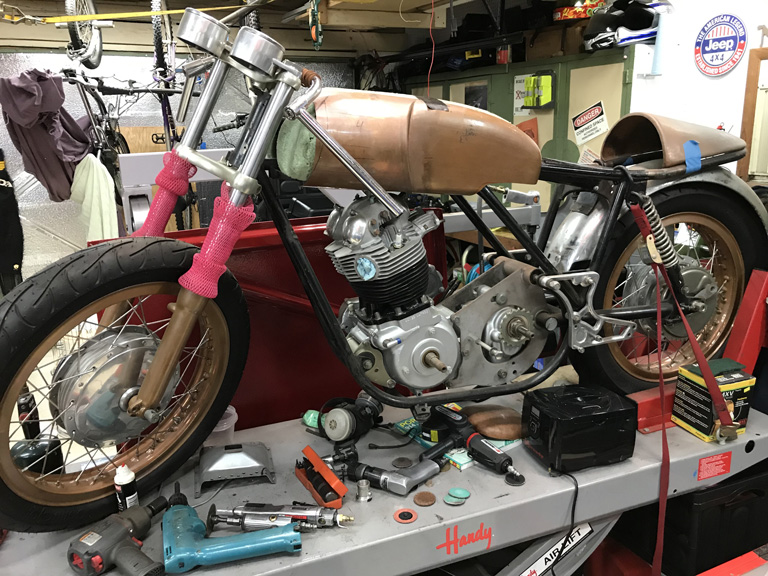
Posted by: Superhawk996 Dec 14 2019, 05:04 PM
Did some supsension work today! Oops. Wrong car. 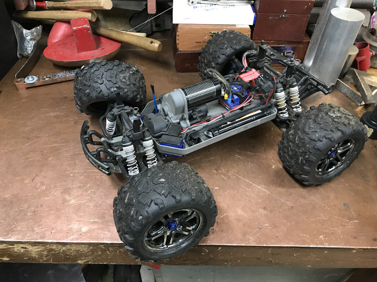
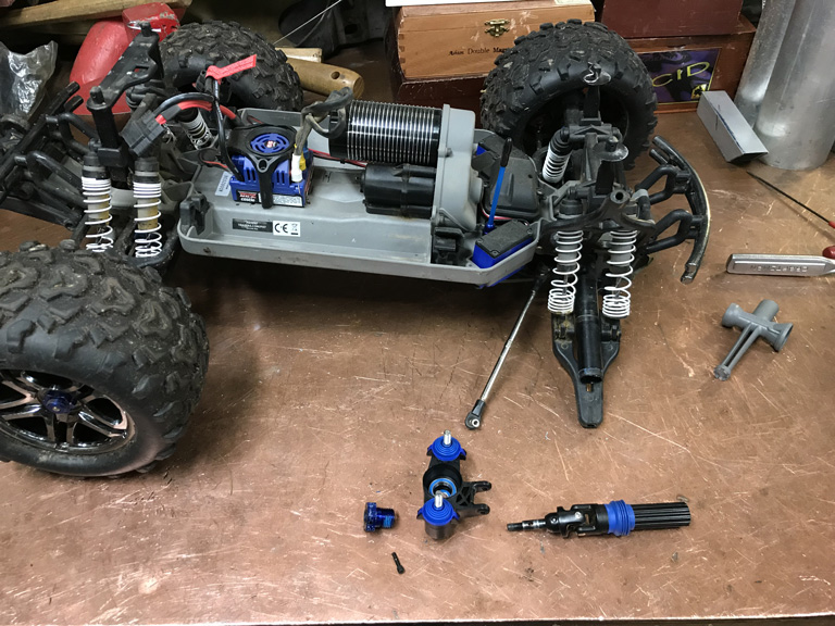
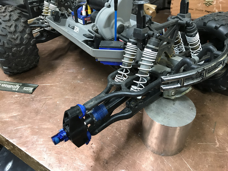
The curent state of RC cars amazes me. Pretty much everything built like a real car but scaled down. Dampers with basic valving and damping adjusted by oil viscosity and/or valve orifice size. Functional & adjustable ball joints etc. Motors are now 3 phase DC brushless and have amazing power and speed for thier size when run on Li-ion!
No real work on the 914 today but this was a fun distraction as I got generators and the snow blower ready for winter. Ran fuel out of all the small lawn equipment, and had to get a few Christmas lights up & operational on timers to keep the wife happy!
Posted by: Superhawk996 Dec 20 2019, 06:24 PM
All right. Time to get serious. On vacation for Christmas and it's time to get back to fixing this rusty chassis.
I've completely forgotten where I was, what I was doing, and wasn't sure whether or not the car has been bumped on it's build cart since I last left it.
Started with a complete remeasurement of the suspension mounting points and comparison back to the orignal measurements. I also established a better centerline than I had been previously using by adding a 3rd point to the centerline and making sure it lies on the other two. Lot of time spent. Seems like this should be quick but it really isn't. 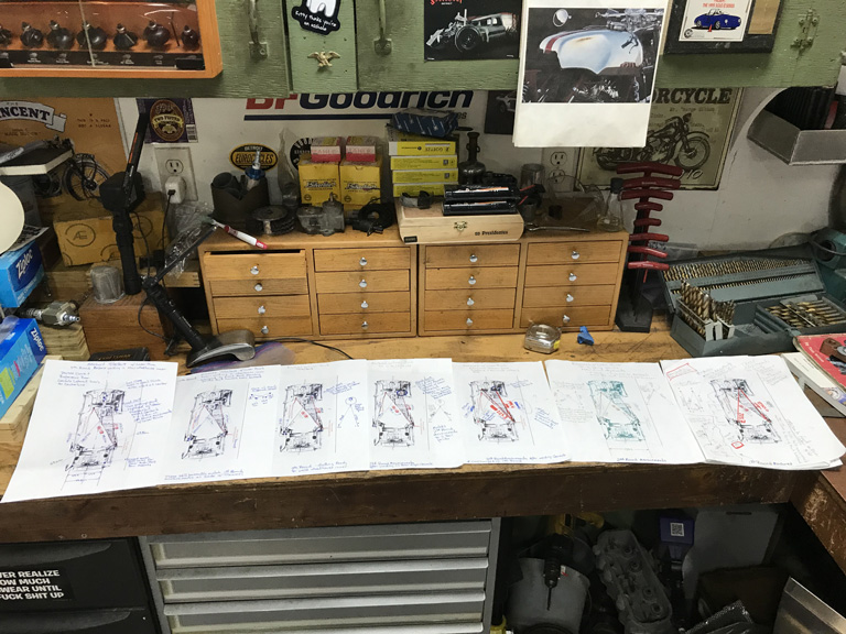
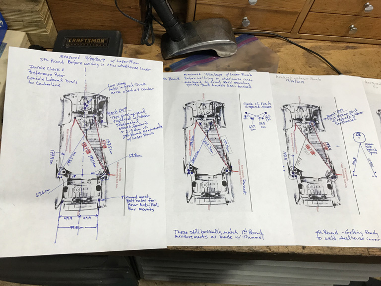
So in total this is the 5th round of measurements I've taken off the vehicle since before any metal cutting was started. Things are still pretty much in the right place.
I had a about a 2-3 mm shift in the right front, rear most steering rack mount when I swapped in the new sheetmetal last spring. This came about since the rank mount hole isn't perfectly on size and will accomodate minor movement of the pickup point within the hole. Overall no big deal but it was a slight shift that I now have to keep track of.
Posted by: Superhawk996 Dec 20 2019, 06:39 PM
On a fun note, the new GT style oil fill neck arrived from the Black Friday group buy that @http://www.914world.com/bbs2/index.php?showuser=9892 put on.
Now I can think about getting holes in the right spot for the dipstick tube and then I can think about closing this up. 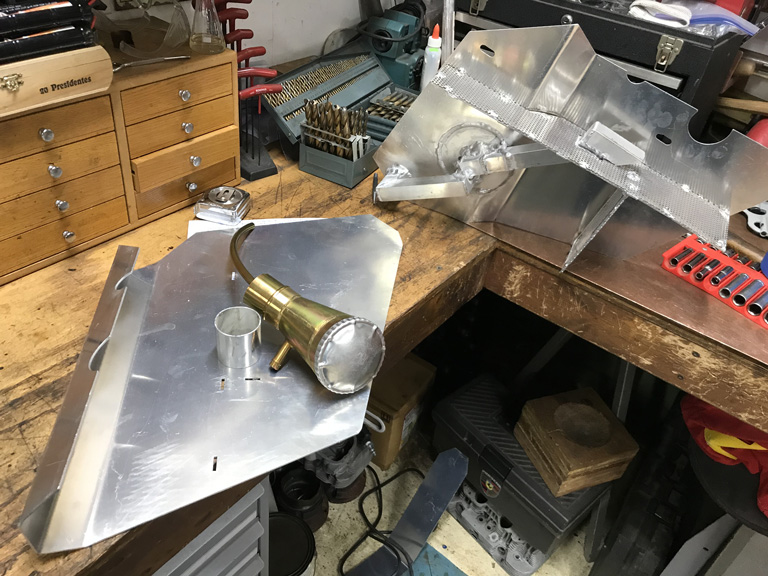
Posted by: mb911 Dec 20 2019, 08:28 PM
Don't forget before you drill holes in the chassis to make a template of the tank
Posted by: tygaboy Dec 21 2019, 09:06 AM
I feel for you Re: your chassis checking.
Don't you just love all the measuring and documenting your measurements then rechecking them to be sure you're not reading the tape upside down or backwards, then worrying you typo'd a number when you wrote it down then wondering if you really had the measuring device in the right location in the first place so you start all over then...
Wait, or is that just me?
Seriously, all your work is looking great. I'm enjoying your build of Ben's @http://www.914world.com/bbs2/index.php?showuser=9892 oil tank. That looks like a fun project. And thanks for documenting all of what you're up to.
Posted by: Superhawk996 Dec 21 2019, 10:05 AM
I feel for you Re: your chassis checking.
Don't you just love all the measuring and documenting your measurements then rechecking them to be sure you're not reading the tape upside down or backwards, then worrying you typo'd a number when you wrote it down then wondering if you really had the measuring device in the right location in the first place so you start all over then...
Wait, or is that just me?
Seriously, all your work is looking great. I'm enjoying your build of Ben's @http://www.914world.com/bbs2/index.php?showuser=9892 oil tank. That looks like a fun project. And thanks for documenting all of what you're up to.
@http://www.914world.com/bbs2/index.php?showuser=19241
Nope not just you . . . my back and ribs are killing me from all the stand up, sit down on creeper, scoot under car. Look for tape measure . . . .damn! Left it on the other side of the car or worse yet, still on bench. Scoot out from under car, sit up, stand up. Go get tape measuure. Repeat the whole sequence again . . . Sh^t wheres my Sharpie? Yeah the measuring gets old real quick. I've totally done re-measure wondering if I had the tape measure on the right point.
I've been watching your project. That is meaurement drama x 10 but your project is looking awesome!
FYI for anyone else doing this, using the laser has been a real winner for me. I've transerred all my points down onto the floor which makes measuring a whole lot easier. It has been way more repeatable than the trammel bar was.
But . . . crap . . . what's the coefficient of thermal expansion for concrete?
The main problem with the trammel is that in order to get accuracy and repeatability the measurement points need to be the same height from the bar and perpendicular to the bar. That is easier said than done, especially when working 18" off the ground and having to deal with the build cart that gets in the way and/or prevents the measurement points from being equal height.
My solution was to use the lathe to put a dimple right on the centerline of the bolt head with a spotting drill. Then shoot the laser plumb up to that point, and then mark the corresponding location on the concrete. Then measure the points on the floor. Ta da, no more errors from unequal length or non-perpendicular trammel points. The laser plumb was cheaper than the trammel bar to boot!
Posted by: Superhawk996 Dec 22 2019, 04:04 PM
Every job that you think you can do quickly will always take longer than you think. Especially if you sort of forgot where you left off.
After measurements were verified, I intended to get down to business and get the wheel house inner welded into position.
Just a couple quick trims to existing sheet metal and off we go . . . . well maybe not.
In order to make a proper butt weld I had to trim back a portion of the inner where it over laps to the sail panel structure. More spot welds to be drilled
For anyone that doesn't believe these cars rust from the inside out maybe this will change your perspective. 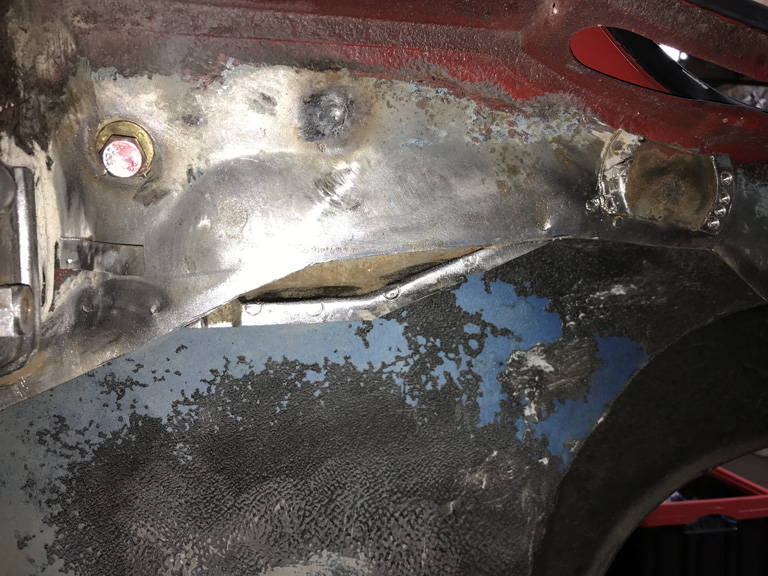
This gives some view into the inside of the sail panel. Not very much rust but it is there none the less. Tin worms never sleep. I used this excavation as an opportunity to break out the Eastwood frame paint/rust neutralizer.
Similarly when I removed the door latch adjustment pocket to get ready for the inner wheelhouse install the tin worms had been at work here too! 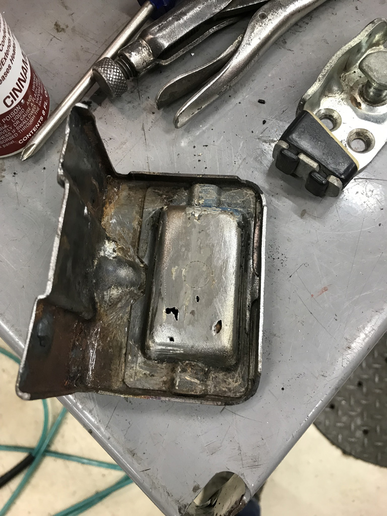
Also found some rust between the door jamb and the adjustment pocket that will get taken care of. This area is heavily sealed with factory seam sealer in this wet area but somehow moisure still get's below the seam sealer and takes root. 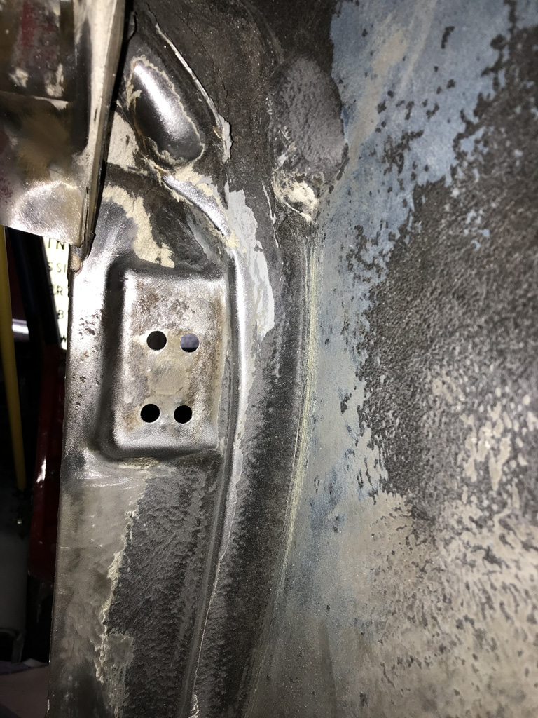
Nothing major but more side work to fix these issues.
Why not just do it right? Sandblasted and then fixed. Just put a simple backing plate was put on the adjuster/striker pocket with a little silicon bronze brazing rod to avoid any risk of potentially burning though thinned metal. This will keep additional water from getting in on the back side of the striker later on. I could probably just have sprayed it over with Wurth seam sealer but there was some risk of the sealer jambing up the adjustment plate. 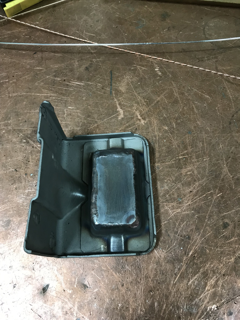
Now we're ready to weld right? Well not so fast. Since I had the blast cabinet fired up, it made sense to do a few other small parts that have been sitting on the bench and will need some paint at the same time I do the inner fender. And of course one of the oil cooler brackets was cracked and needed a quick weld. 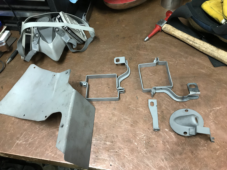
Posted by: Superhawk996 Dec 22 2019, 04:09 PM
Since I had already sprayed the sail panel inner with the rust neutralizer and the garage smelled of fumes I decided to do the inner wheelhouse while access is easier.
Flooded the supension console and drilled a couple drain holes into the jack post and then flooded that too for good measure as suggested by @http://www.914world.com/bbs2/index.php?showuser=7300 .
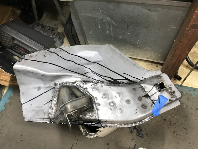
Don't worry, didn't leave all the paint trails all over the place. They were cleaned up later. And gave a light spray coat to the inner frame rail 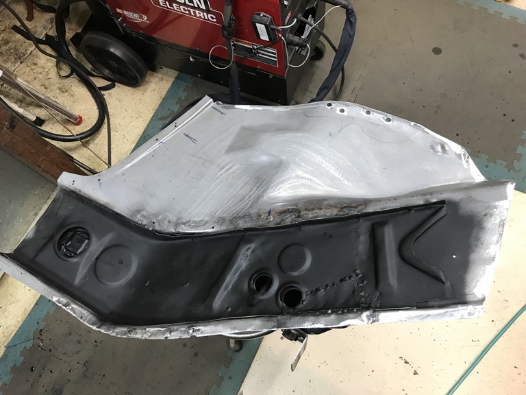
And while I was working inside the hell hole, it was prime time to get rid of the terrible worn trunk hinges that are worn and mangled, and poorly repaired previously. More spot welds. 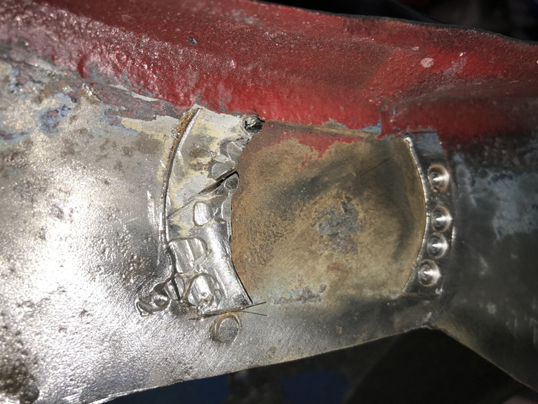
I still need to get a coat of epoxy primer on the fender inner while access to that area is wide open. . . . maybe tomorrow.
Posted by: Superhawk996 Dec 25 2019, 12:11 PM
Yesterday I was able to get in some work on the oil tank between family events.
Not exactly my finest hour. I had some trouble finding the right hole location for the dip stick tube. Due to the curvature of the tube and the variability of the hole as the oil fill neck installs laterally, it wan't a simple one cut operation.
In fact, I ended up cutting and slotting multiple holes until I found the right spot. 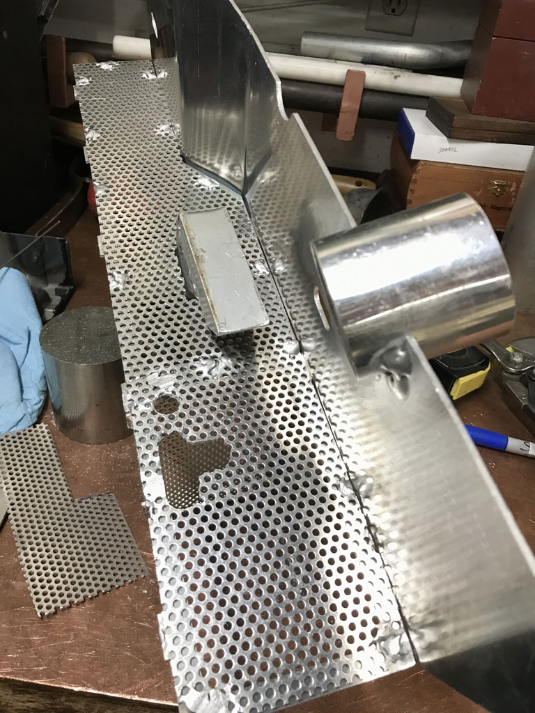
When it was all said and done, I ended up having to paste a small portion of the screen back over the healthy oversized hole. 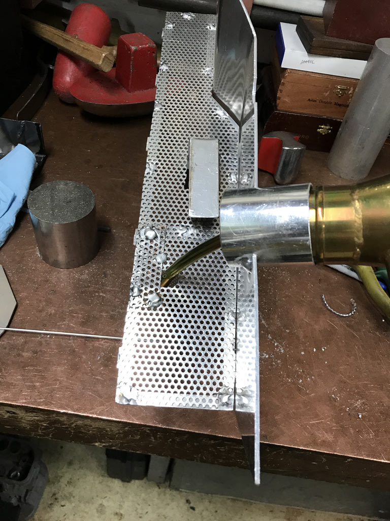
All in all I'm happy with the final position of the dipstick, just wish I had come up with a better way to locate the hole besides trial and error. 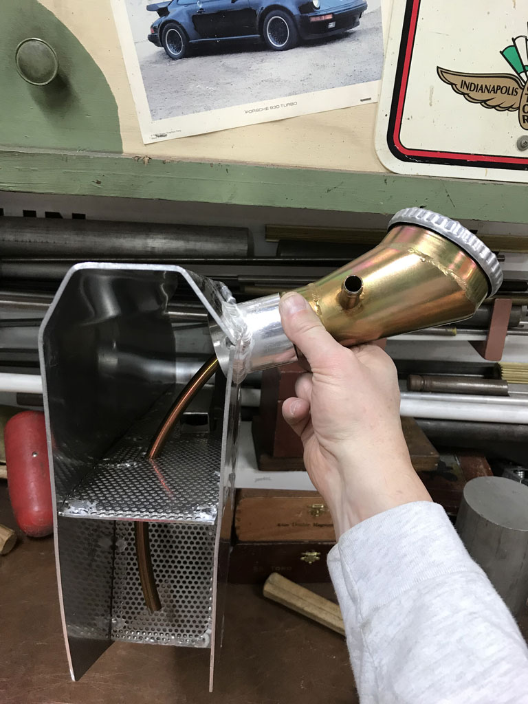
Still need to add on the mounting bungs and a baffled breather tube before I button up all of the sides. 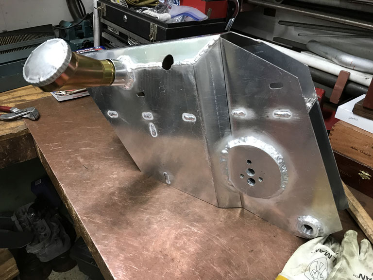
Posted by: Cairo94507 Dec 25 2019, 12:53 PM
That is very nice work. I know we are our own worst critics, but that looks nice to me.
Posted by: tygaboy Dec 25 2019, 01:10 PM
Nice!
Posted by: mb911 Dec 25 2019, 04:59 PM
I think its just fine.. I do my different by putting the bypass closer to the front and then leave the spot the dipstick tube goes into much larger.. The vertical baffle gets everything else. I do also leave about 1/2" of the vertical baffle off of the floor of the tank.. Just in case of blockage.
Posted by: Tdskip Dec 26 2019, 08:14 AM
Thanks for all of the updates, including the RC car.
Posted by: Superhawk996 Dec 26 2019, 09:01 AM
The tank project has been great filler work for the few hours that I could get in amongst the holiday events.
The problem is when doing hit or miss work, it is easy to miss the obvious in the rush to get something done. In my case, this was the failure to put the tank mounts on while I still had access to the internal side of the tank.
It would have been simple to just weld the mounting bungs on from the backside with a nice fillet weld and then I would have been done. Strong, no risk of leakage.
But nope, I forgot in the rush to paste the front and back side of the tank together.
So this meant welding them primarily from the front and trying to make sure that I had good penetration and also fully sealed them from leakage. Of course this required welding close the the aluminum threads and that a shaky hand and/or wandering arc would melt a few. And to top it off the weld bead ended up partially obsuring the threads so it wasn't even possible to get a tap started.
The solution was to counter bore the threads with a 5/16" end mill to clear away the weld bead and to take out the 1st couple of threads deformed by welding. 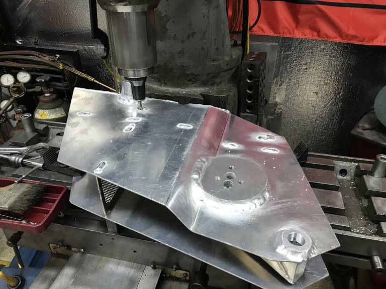
At this point I decided that I should probably build up the weld bead and make a nice flat mounting surface. 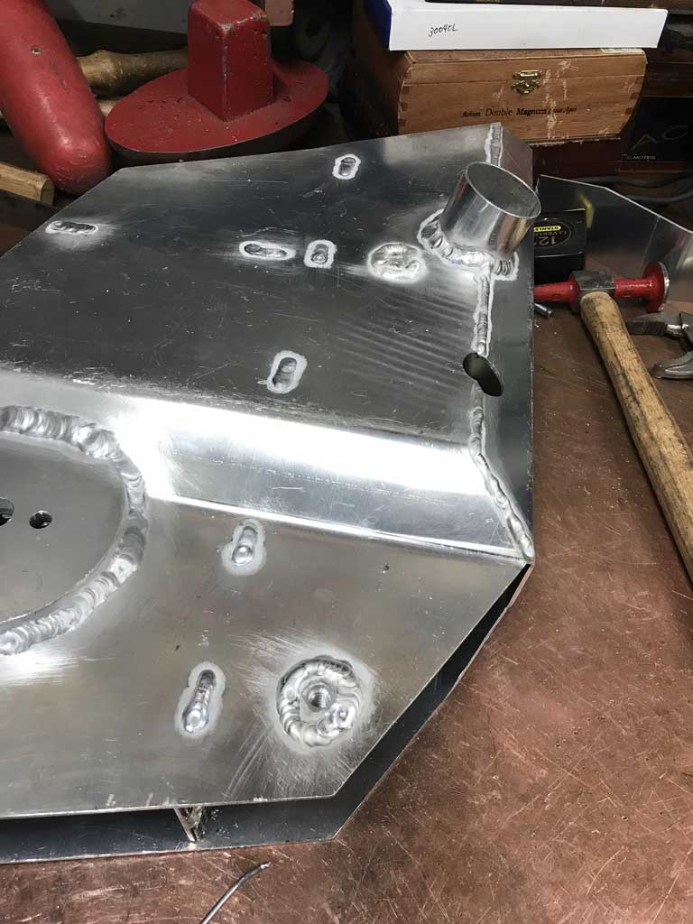
Then milled that surface flat and closer to the tank. 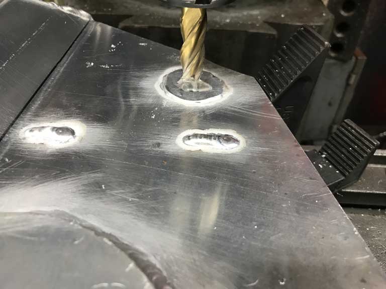
In the end, it turned out fine, I'm sure I have plenty of weld penetration to fuse the tank to the mounting bung and that there will be no leaks. It just involved a couple of hours of work that could have been avoided had I done the assembly in the proper order. 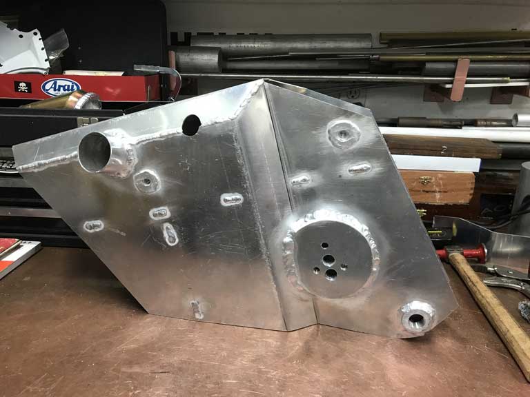
Posted by: FourBlades Dec 26 2019, 09:43 AM
Looking good! I never knew those oil tanks had so much going on inside them.
No wonder the aftermarket ones cost what they do.
Great work on your restoration, keep it coming!
John
Posted by: eatpez Dec 26 2019, 04:05 PM
@http://www.914world.com/bbs2/index.php?showuser=22428
Out of curiosity, what media do you prefer to use in your blast cabinet?
Posted by: Superhawk996 Dec 26 2019, 04:22 PM
@http://www.914world.com/bbs2/index.php?showuser=22428
Out of curiosity, what media do you prefer to use in your blast cabinet?
@http://www.914world.com/bbs2/index.php?showuser=22543
Usually use HF Aluminum Oxide in my very small benchtop cabinet. It lasts a lot longer and cuts better than sand or glass bead.
Sometimes I'll switch over to glass bead if necessary but it is a royal PITA to make the switch and too much time is lost cleaning out the Aluminum Oxide with no real guarantee that some won't come out of some nook and cranny. Only do this with non critical parts.
Glass bead wears out very quickly (like after 2x being shot) so I usually just shoot glass bead from a pressure pot outdoors and let it scatter and don't try to reuse it.
Tried Silicon Carbide once, like it, was pretty long lasting, but it is very pricey (2x-3x) the cost compared to Aluminum oxide.
Posted by: Superhawk996 Dec 31 2019, 10:11 AM
Almost finished up with the oil tank.
Put the sides on but ran into a slight glitch, I've had a little bit of twist enter the tank as I welded up the inner baffles. The net effect is that I had to split one of the tank side pieces in order to accomodate the slight twist. 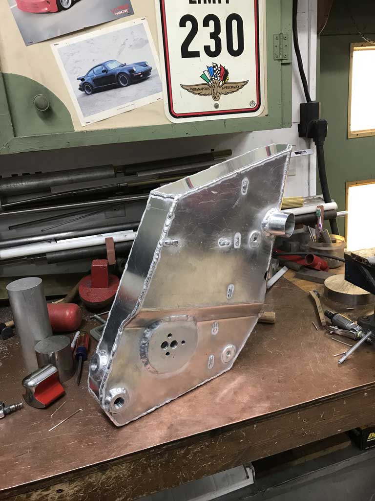
Hopefully this doesn't come back to haunt me later.
I've also wanted to fabricate a labryinth baffle for the tank breather. My first attempt with a couple of drilled discs was a failure and was far too restrictive. Currently working on a 2nd version. This style with just two staggered plates should allow for better breathing. 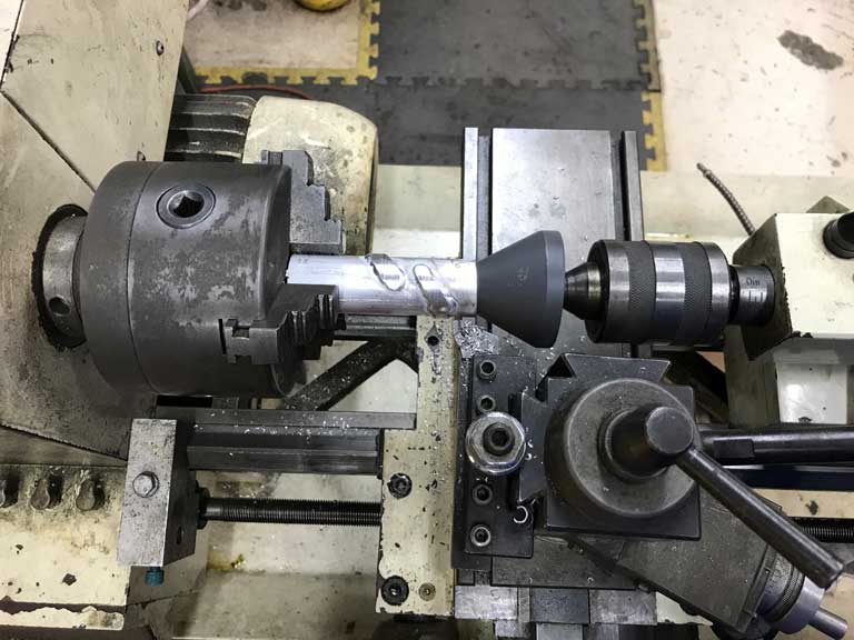
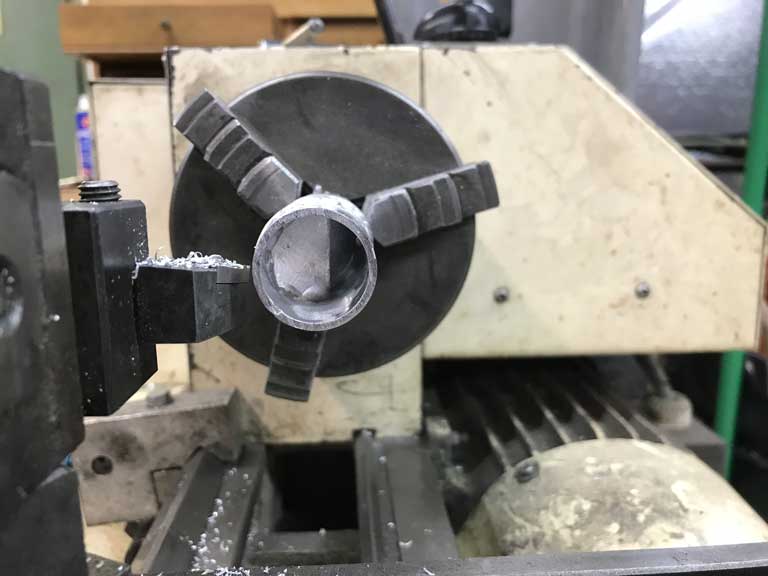
Hope to put the finishing touches on this tank today.
Posted by: Superhawk996 Dec 31 2019, 10:20 AM
I've also been spending some quality time in the hell hole.
Managed to get the wheelhouse inner welded in without moving the outer suspension console pick up points. Pretty happy so far. 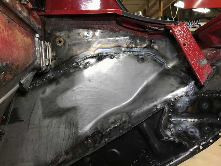
Good weld pentration on the butt weld that will allow the inside engine area to be ground flat but I will leave the bead on the exterior side for strength and it will eventually get covered either with undercoat or possibly reinforced later with the GT stiffening plate kit. 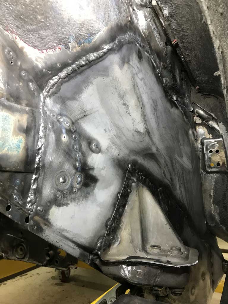
Still need to get the door latch striker welded in today.
Things will get trickier as I install the inner C-section of the longitudinal to this wheelhouse. If things dont fit perfectly the C section is much more rigid and will easily pull the flat wheel house sheet metal out of position.
Posted by: bkrantz Dec 31 2019, 09:19 PM
I've also been spending some quality time in the hell hole.
Managed to get the wheelhouse inner welded in without moving the outer suspension console pick up points. Pretty happy so far.
Good weld pentration on the butt weld that will allow the inside engine area to be ground flat but I will leave the bead on the exterior side for strength and it will eventually get covered either with undercoat or possibly reinforced later with the GT stiffening plate kit.
Still need to get the door latch striker welded in today.
Things will get trickier as I install the inner C-section of the longitudinal to this wheelhouse. If things dont fit perfectly the C section is much more rigid and will easily pull the flat wheel house sheet metal out of position.
Nice work! Where did you source the inner wheelhouse panel? I need to replace mine, but only above the frame member.
Posted by: Superhawk996 Jan 1 2020, 11:43 AM
Where did you source the inner wheelhouse panel? I need to replace mine, but only above the frame member.
@http://www.914world.com/bbs2/index.php?showuser=23343
AutoAtlanta has them. The upper secion is a bit tricky due to the formations in the metal this piece would be time consuming to fabricate from scratch. Could definately be done with but for the price, you can't beat the time saved vs. fabricating the whole thing from scratch. If you just need the upper, I'd buy this whole piece and just cut off the lower rail you don't need. Probably could resell the balance of the lower to someone in need on Classified Forum as a partial cost offset. If you just need a small section, then you'd be better off to fabricate from scratch.
The only thing I can gripe about is the panel has some wrinkling in it that I wish wasn't there. a light skim of filler will hide them.
In AA's defense, the panel has quite a bit of die draw and has a complicated form to it and isn't a simple stamping to recreate. I'm sure that the tooling to crate this wasn't cheap and probably either has some wear, and/or the stamping shop doesn't quite have all the details worked out beteen the tension on the binder, the lubrication or any number of other variables involved in stamping a part this complex.
I'm grateful it is available.
It did fit quite well and only required minimal hammer and dolly work to blend it to my vehicles existing structure.
Tthe other caveat was that in my case, it appears that there may be about 0.060" less draw to this panel vs. my original. I had to put .064" of spacer on the back side of my door latch to get the proper alignment of the latch stricker hole and to have it simultaneously touch off the wheel house inner for spot welding.
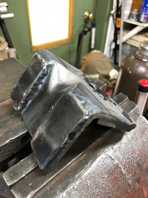
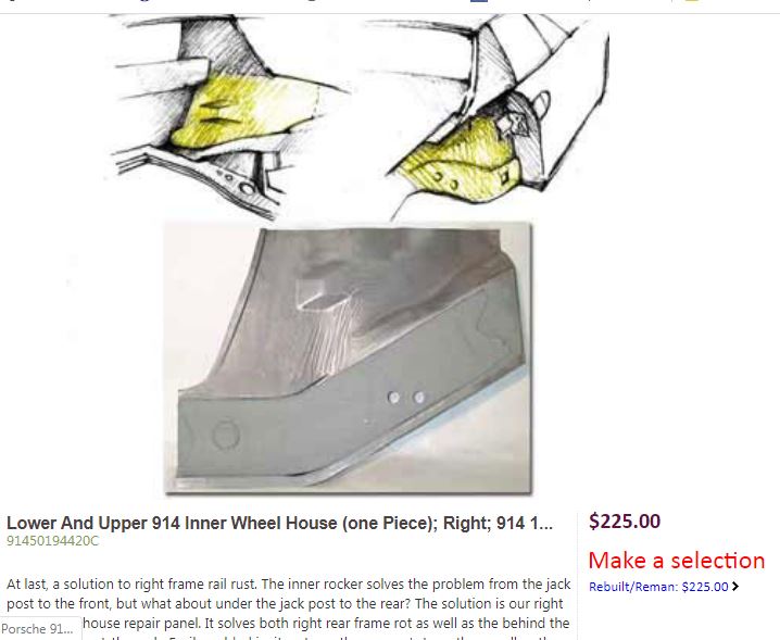
Posted by: bbrock Jan 1 2020, 11:48 AM
I got mine from Restoration Design (right side only) and was happy with the part: http://www.restoration-design.com/store/product/PP331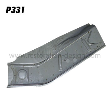
Posted by: Superhawk996 Jan 1 2020, 11:57 AM
I got mine from Restoration Design (right side only) and was happy with the part: http://www.restoration-design.com/store/product/PP331
@http://www.914world.com/bbs2/index.php?showuser=20845 .
Did it extend up higher to full height or was it just this lower portion only? I originally looked at RD but thought this was only the lower. From @http://www.914world.com/bbs2/index.php?showuser=23343 post, I think he is looking for the upper portion only.
Posted by: bbrock Jan 1 2020, 12:58 PM
I got mine from Restoration Design (right side only) and was happy with the part: http://www.restoration-design.com/store/product/PP331
@http://www.914world.com/bbs2/index.php?showuser=20845 .
Did it extend up higher to full height or was it just this lower portion only? I originally looked at RD but thought this was only the lower. From @http://www.914world.com/bbs2/index.php?showuser=23343 post, I think he is looking for the upper portion only.
It is the lower only as seen in the pic. I did do a bit of patchwork in the upper section but the areas I had to do were easy to fabricate.
Posted by: bkrantz Jan 1 2020, 10:31 PM
I got mine from Restoration Design (right side only) and was happy with the part: http://www.restoration-design.com/store/product/PP331
@http://www.914world.com/bbs2/index.php?showuser=20845 .
Did it extend up higher to full height or was it just this lower portion only? I originally looked at RD but thought this was only the lower. From @http://www.914world.com/bbs2/index.php?showuser=23343 post, I think he is looking for the upper portion only.
Yes, I need only the upper section, with all the compound curve shapes.
Posted by: Daryl32 Jan 25 2020, 01:35 PM
OK Oscar, you have put my work to shame....
What you are doing is so far out there for a DIY in the garage venture!
Hats off to you -
Posted by: Superhawk996 Jan 27 2020, 07:19 PM
Lots of work the last 3 weekends in the aptly named Hell Hole.
1st week was prepping the part of the rear longitudinal that attaches to the wheelhouse inner.
I nearly forgot to put on the two weld studs that secure the trunk torsion springs. 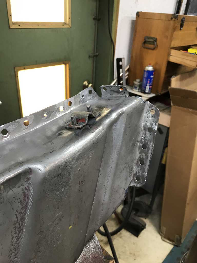
Then there was the obligatory hole drilling for the puddle welds and then painted the inside of the C-section with Eastwood frame coating but masked the weld flanges to keep them clean. 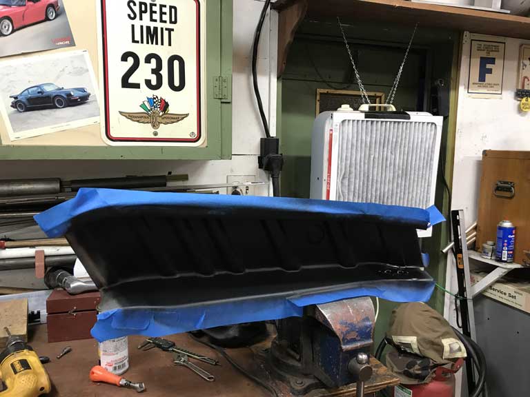
This Eastwood coating really seems to take the heat well and doesn't flake off after the heat of welding in the vicinity but at the same time I'm going really slow and making sure the overall sheet metal outside the immediate weld area doesn't heat up beyond what I can touch with a bare hand. This makes for really slow welding.
Of course there was a lot of time spent tweaking fits and getting the frame angle to match the driver side. 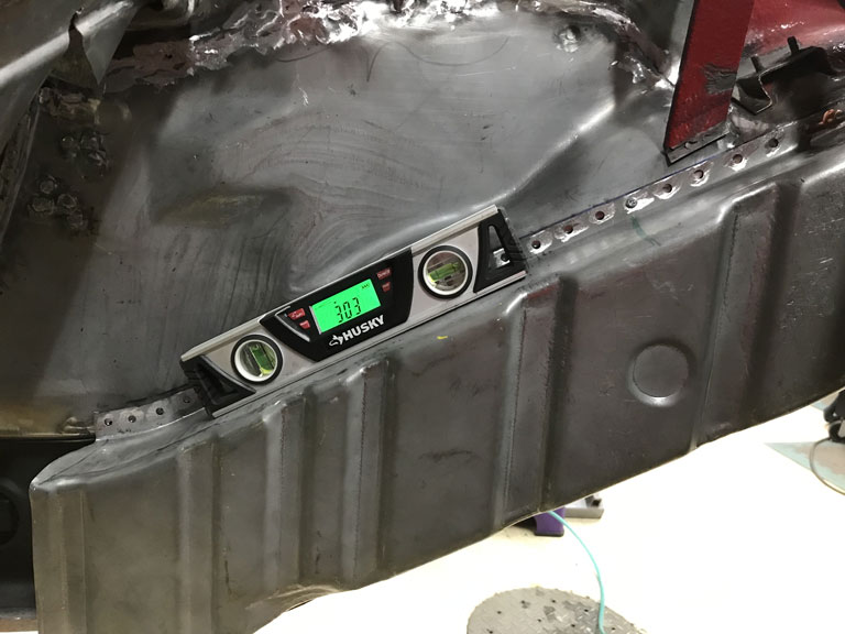
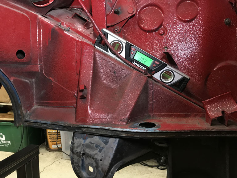
The attachement to the rear of the engine compartment and the front of the rear shock tower is a special kind of hell. 1st the area had to be cut open which of course was done long ago. But even so I ended up not quite gettting the top frame tab where I would have liked. I couldn't close up the air gap between the tab and the shock tower. Trying to do the puddle welds would have just resulted in buring out the flange and/or a giant booger weld. Ultimately I decided to live with this and do a couple little stitches where I had solid metal to metal contact since that little top tab really isn't carrying much load. The side flange and the bottom flange will take most of the load. 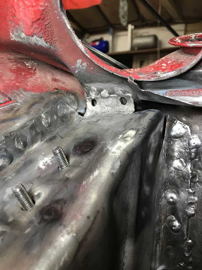
To top all that off, there is very little room inside this box section to manipulate the torch.
When it was all done, I dusted the tuna can flap with some Eastwood in anticipation of being able to put that flap back in postion either this week after work or early in the weekend. 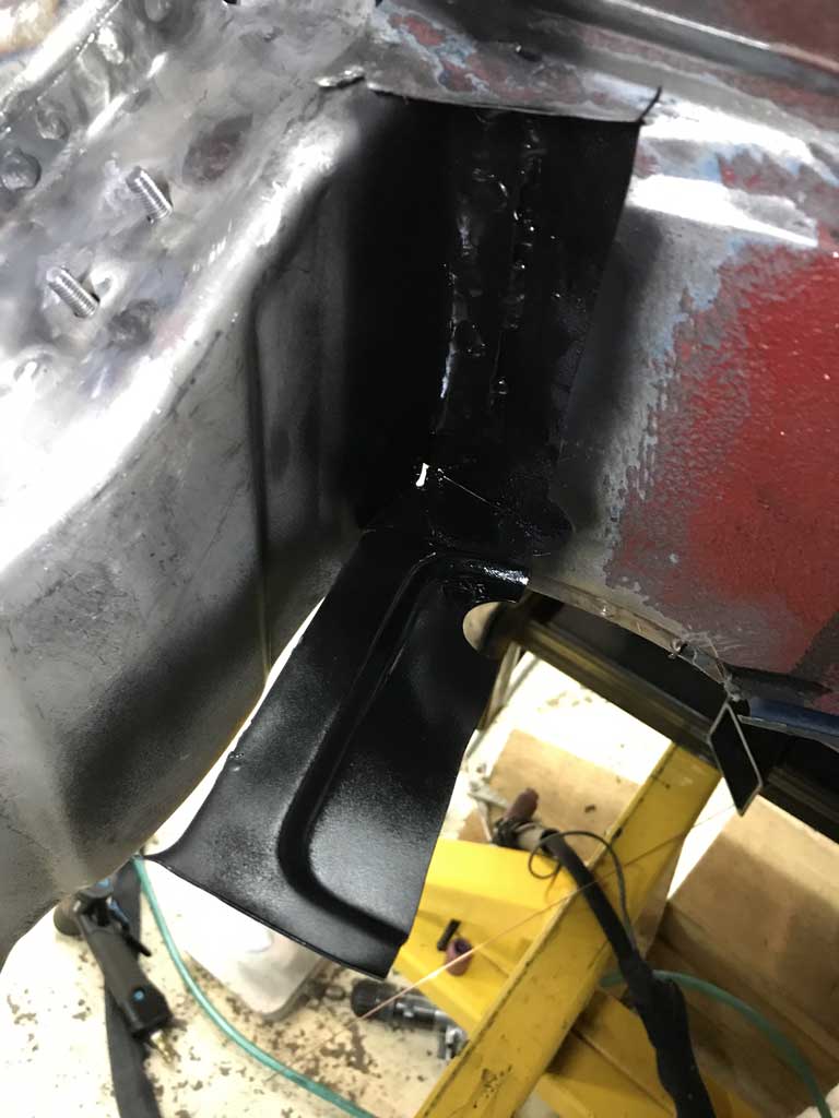
Lots of out of position welding on this section and the need to weld slowly, and constantly monitor the outer rear trailing arm pick up points for movment made this a slow painful ordeal. When it was all said and done, the suspension points hadn't moved so I'm going to call this past couple of weeks a success.
Posted by: bbrock Jan 27 2020, 10:25 PM
Nice work. Don't take this the wrong way, but it's nice to see someone of your skill complaining about all those awkward places where there is no room to manipulate the torch. Gawd those were frustrating.
Posted by: Superhawk996 Jan 28 2020, 08:14 PM
I dont know your 911 2.4 plan, but the 2.4 cis intake ports are tiny..Ollies gonna bore em out ??
Also as you did on the type 4sale case is what I do to the 2.4 cis inj. ports press in a shaft and weld the the top..when porting , smooth transition...lots of irons in the fire..
@http://www.914world.com/bbs2/index.php?showuser=2744
Finally decided. Ollies actively working on the heads. 34mm intake and leave exhaust stock. 1973 2.4l spec 911E was 32mm. 911S 36mm.
Smallest PMO ITB EFI manifolds are 34mm which is what I plan to use for induction. I don’t want to build a S spec motor so I feel 34mm splits the difference, will breathe a bit better than E spec and will allow me to get to modern FI.
Hopefully it all works as planned
Posted by: Superhawk996 Jan 28 2020, 08:18 PM
Nice work. Don't take this the wrong way, but it's nice to see someone of your skill complaining about all those awkward places where there is no room to manipulate the torch. Gawd those were frustrating.
@http://www.914world.com/bbs2/index.php?showuser=20845 . Thanks just trying to keep up with your precedent
Looking forward to some Idaho time and a few days of skiing in the near future! Missing the mountains!
Posted by: sixnotfour Jan 28 2020, 08:30 PM
Good choice.... Ive done em all...Right down the middle.....solex cams ...
Posted by: Superhawk996 Jan 29 2020, 05:50 AM
Good choice.... Ive done em all...Right down the middle.....solex cams ...
@http://www.914world.com/bbs2/index.php?showuser=2744
Are you running carbs or FI?
Posted by: sixnotfour Jan 29 2020, 10:44 AM
Good choice.... Ive done em all...Right down the middle.....solex cams ...
@http://www.914world.com/bbs2/index.php?showuser=2744
Are you running carbs or FI?
webers,,,
Posted by: Superhawk996 Feb 2 2020, 09:31 AM
Had great aspirations for a weekend of welding but got busy at work and forgot to check how much Argon I had left. Turns out, not enough. Talk about a failure to plan biting me in the butt!
Started to put the flap of the rear engine bulkhead back into place but ran out of argon. 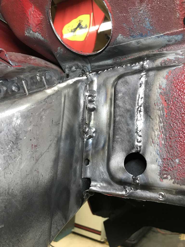
No shortage of other things to do.
Heard from Ollie's that my 2.4L mag case is going on vacation to CA for some welding along with some of it's other mag case friends. In talking with them it sounds like they are seeing more and more mag cases that have corrosion, sunken deck registers, and other isssues as they age that require more extensive rework than was the norm say 20 years ago. Was happy to hear that is well underway though!
Posted by: bkrantz Feb 2 2020, 09:18 PM
Could be dumber. I went out the other morning, got all set up, and started welding without opening the gas valve. Took me a few minutes to figure out why my weld puddle was splattering.
Posted by: bbrock Feb 3 2020, 08:14 AM
Could be dumber. I went out the other morning, got all set up, and started welding without opening the gas valve. Took me a few minutes to figure out why my weld puddle was splattering.
Can't count the number of times I've done that. And while sputtering crappy welds thinking, "what the heck is wrong with this welder now." The answer was always the dumbass holding the nozzle.
Posted by: tygaboy Feb 3 2020, 09:36 AM
Could be dumber. I went out the other morning, got all set up, and started welding without opening the gas valve. Took me a few minutes to figure out why my weld puddle was splattering.
Can't count the number of times I've done that. And while sputtering crappy welds thinking, "what the heck is wrong with this welder now." The answer was always the dumbass holding the nozzle.
I think I have you beat. I do that so often that as soon as the first weld "fails", I know EXACTLY why!
Posted by: Superhawk996 Mar 8 2020, 06:01 PM
Well February basically slipped away with very little 914 work.
Was traveling for work, a bit of vacation and then manged to get sick on vacation with a really nasty case of Bronchitis.
So it's March and time to make some progress.
Now that I have the wheelhouse inner and the inner frame rail in place I was able to weld my lower longitudinal bracce back in place in anticipation of putting the inner longitudinal back in place. 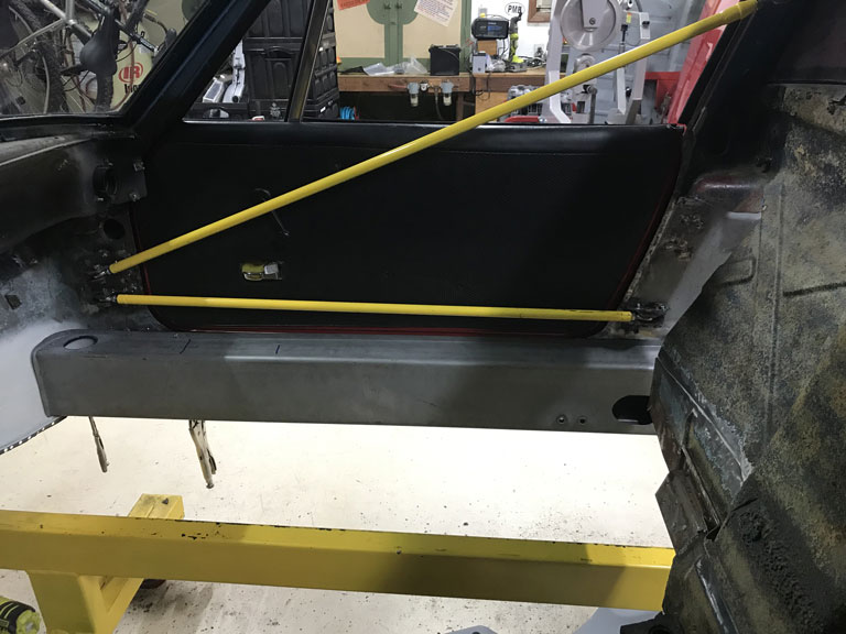
Spent some time evaluating the door gaps 1st with a simple gauge set to 1039mm "h" dimension from the door swith to the door striker plate. 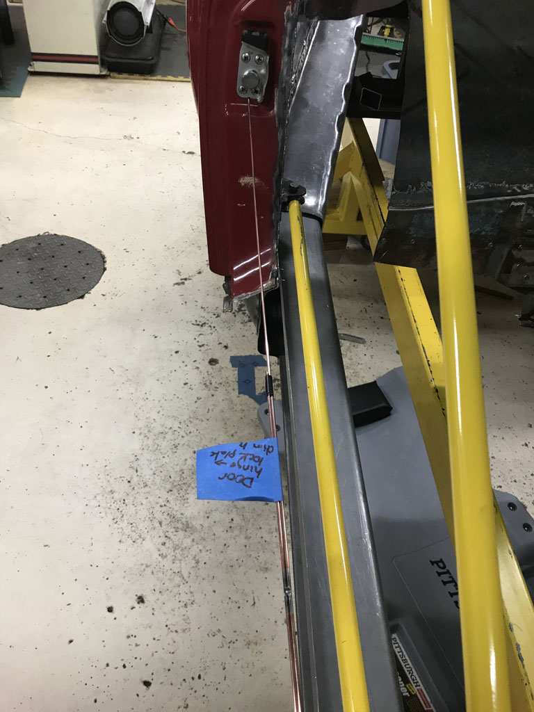
Then finally visual and just measuring to see how consistent I could get them visually. Not too bad. 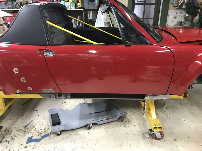
The slow part of this is that after tweaking things, I constantly have to go back and measure the rear suspension console to front suspension dimensions to make sure nothing has moved too far out of whack. Luckily, what I found is that by adding the brace, I was able to pull the lower door opening back to where it was before I welded in the wheelhouse inner and the inner frame inside the hell hole.
Started prepping the longitudinal inner by putting the heater tube pipe back in place and painting the inner with Eastwood frame paint. 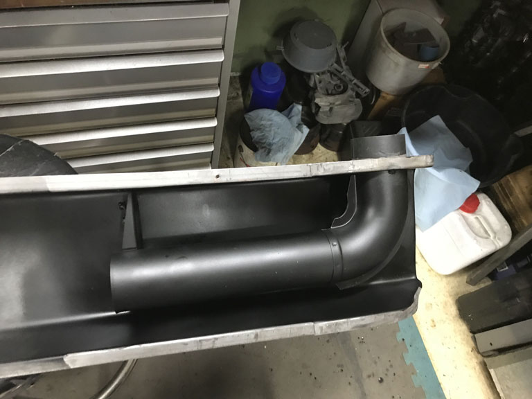
Unfortunately that sort of burned out the day.
Posted by: Superhawk996 Mar 14 2020, 04:42 PM
Completed the build out of the longitudinal today. With a little luck, I'll get the long welded in tomorrow or at least tacked in for yet another round of suspension measurements.
Started by mocking it up using Cleco's 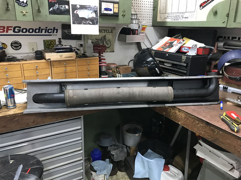
Decided to use solid rivits to secure the spring steel heater tube holders to the long. Same as the OEM attachment method. 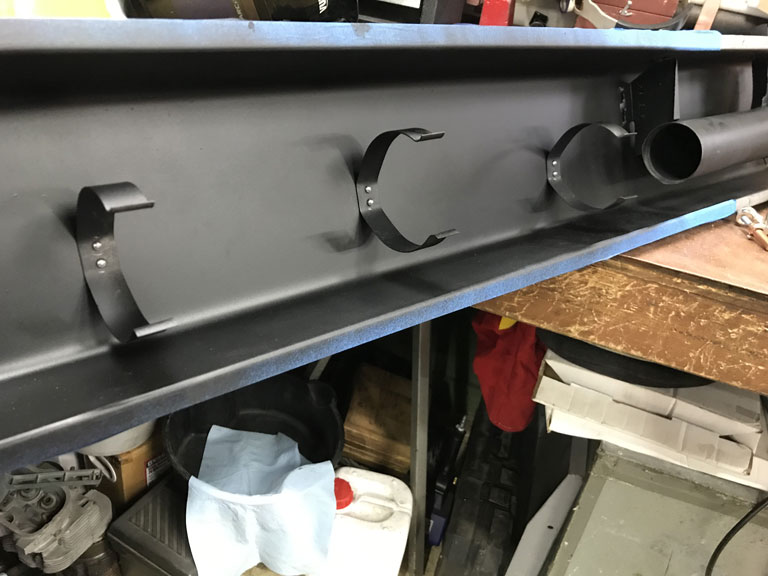
Unfortunately the reproduction longitudinal doesn't have the same offset recess as the original. This leaves the bucked rivets overflush to the longitudinal inner surface. 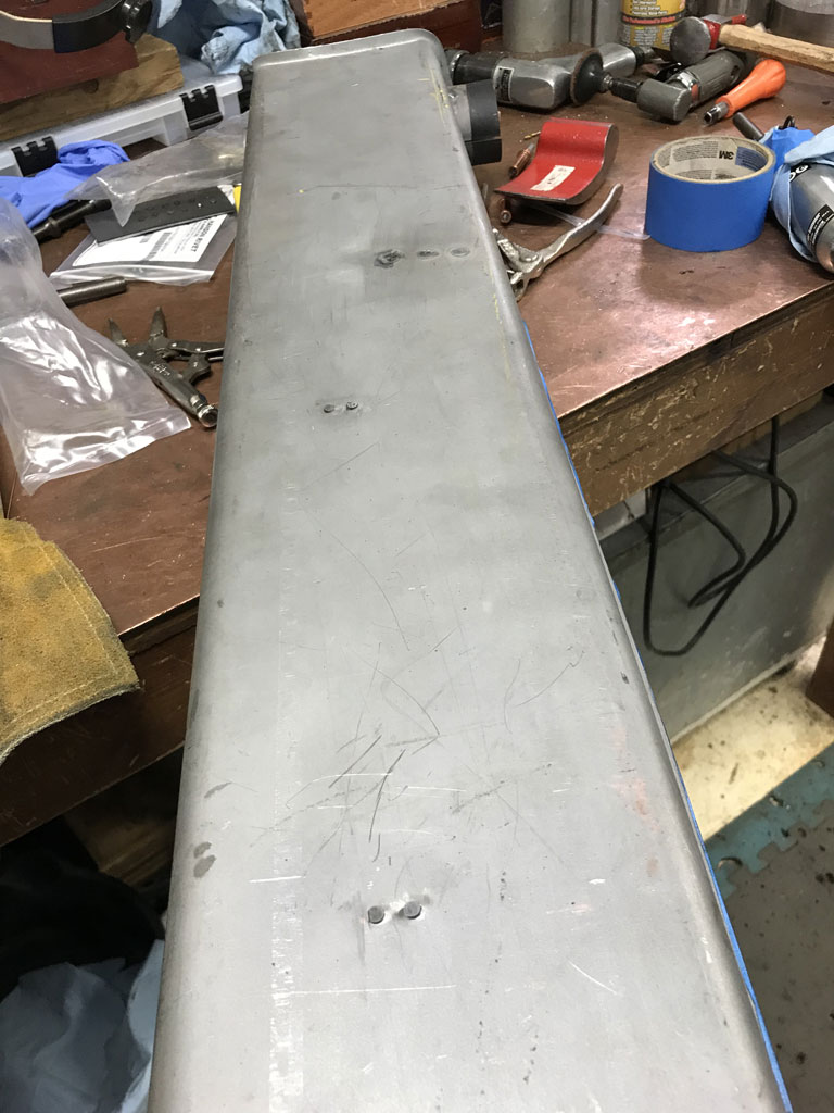
Hopefully these don't show though the carpet later on. I guesss in the worst case, I could put a thin layer of open cell foam over them to help smooth things out. Least of my worries at this point.
Posted by: bbrock Mar 14 2020, 06:37 PM
Those longs don't appear to have the recesses stamped into the bottom either. Glad to see someone else OCD enough to use solid rivets on the hose brackets. I don't know why I did it, but it had to be done. I can't imagine those rivets will show through the carpet.
Posted by: tygaboy Mar 14 2020, 07:11 PM
You had me at "Clecos"...
Posted by: Superhawk996 Mar 14 2020, 07:57 PM
Those longs don't appear to have the recesses stamped into the bottom either.
Yeah. Not to thrilled about that. I looked around at AA and RD and it didn't seem to me that anyone really had a longitudinal that was a true reproduction.
I get it. It would be a more complex tool and ultimatley no one really sees it directly once installed.
Would have been nice to have the option for 100% reproduction though! I guess I'm just happy to have the part at all.
Posted by: Superhawk996 Mar 17 2020, 09:05 AM
After a year apart, the front of the vehicle has been reunited with the rear. 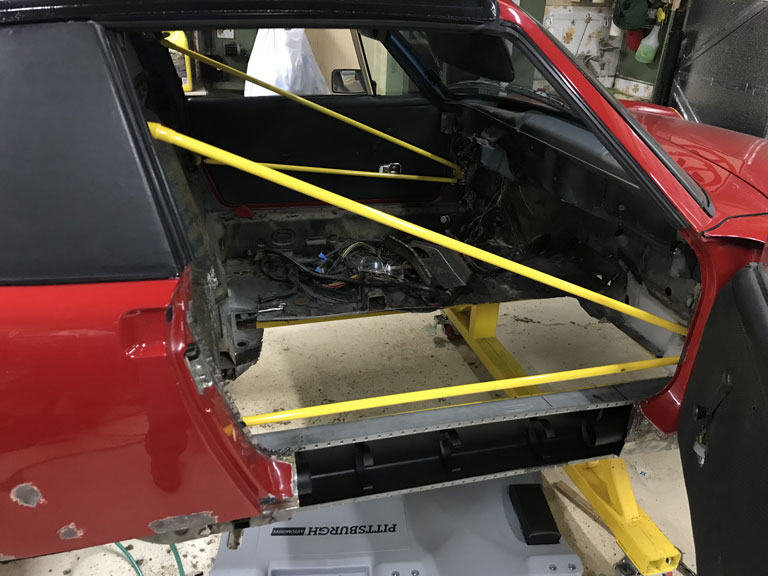
In the process of getting ready to weld the long to the front fender area I had to clear off some primer and I got carried away. I decided to strip the undercoating out of the fender well. Love the flail wheel for this. Makes quick and easy work of it and can do so without completely stripping the OEM paint underneath. 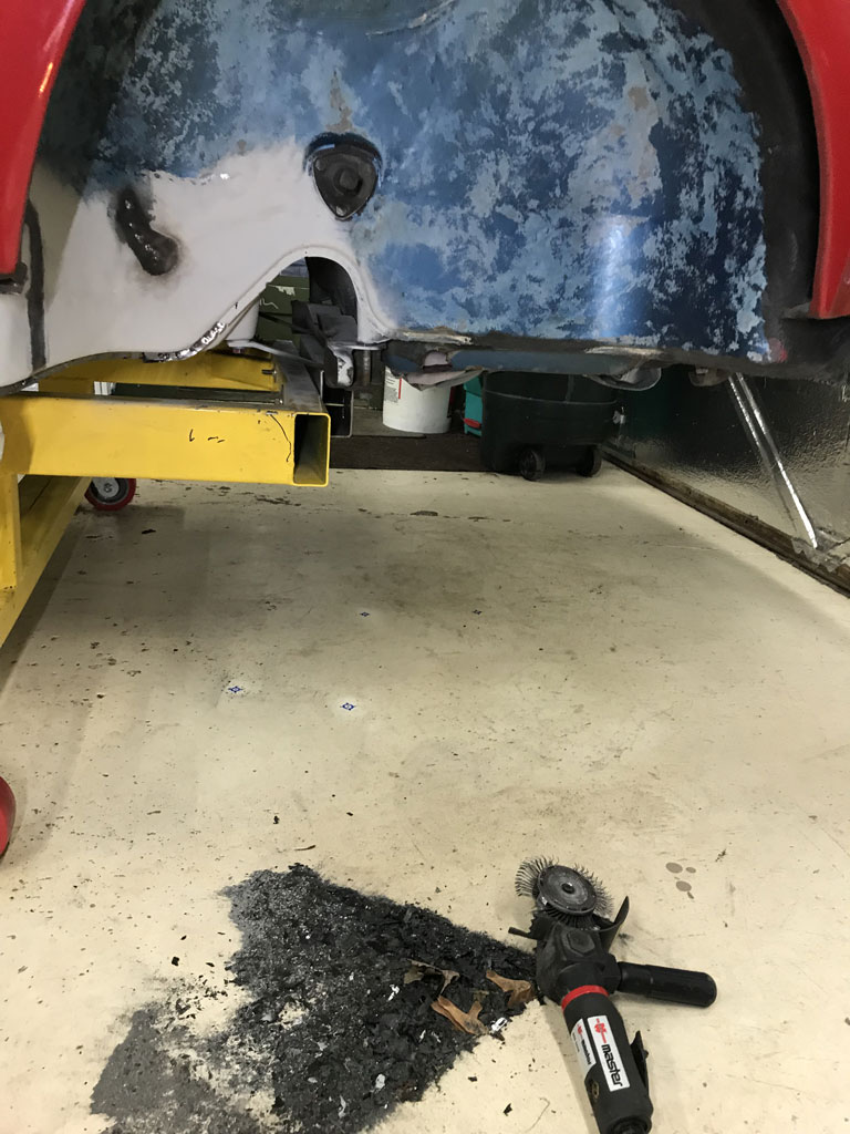
In the process, I'm now noticing that the passenger side front fender has been replaced at some point - potentially in conjunction with prior accident (on left side) that probably led to the addition of flares? Odd. Color of the panel looks like it might have been NOS sheetmetal. The underside of the panel certainly wasn't primered with the same primer as the panel exterior. Ah, the mysteries of a vintage car. If only they could speak and tell the tale. 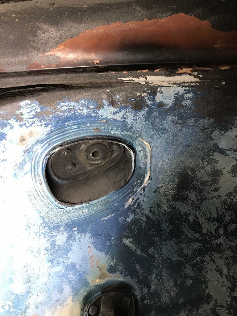
Will update my VIN registry to reflect non-OEM front passenger side fender.
Posted by: Superhawk996 Mar 21 2020, 01:35 PM
Fitting up the longitudinal outers. Finally starting to feel like some progress is being made. 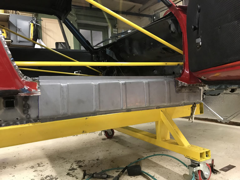
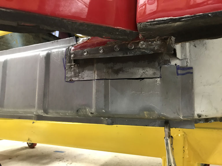
Posted by: bbrock Mar 21 2020, 01:49 PM
Such a great feeling when those outer longs go on.
Posted by: Superhawk996 Apr 4 2020, 02:18 PM
@http://www.914world.com/bbs2/index.php?showuser=20845
@http://www.914world.com/bbs2/index.php?showuser=9892
@http://www.914world.com/bbs2/index.php?showuser=19241
@http://www.914world.com/bbs2/index.php?showuser=1570
Need some tribal wisdom. Maybe talk me off the ledge if it's warranted.
Before I welded in the passenger side outer long I had the passenger side door gaps just about perfect with what I thought was a hint of preload on the wide side.
I welded so slowly it took about 3 days of on/off welding to get this bugger buttoned up. I knew that when I removed the door braces I'd have some shrink.
I think I got a little more than I expected and definately more than I wanted.
It seems to me that my passenger side door gap is a hint too tight (3mm but consistent). Being an OCD engineer, I'm on the verge of starting to cut welds and trying to push it back out and then reweld. I don't like this idea either since that opens up all sorts of possibilites for further screw ups and more shrinkage.
For what it's worth this car has been hit in the left front and was clipped so it's not like I have a virgin driver side to measure from. Although it was clipped, I've spent tons of hours measureing my suspension pick up points, door post gaps, header to roll bar gaps, etc., none of these has moved since welding in the longitudinal.
3mm gap just looks too tight to me. But at the same time it seems crazy to try to cut & re-weld for 1 - 1.5mm of improvment.
Well, here's what I have. Although you can see the door braces in the photo, they are just leaning on the firewall, not connected to anything.
Passenger side overall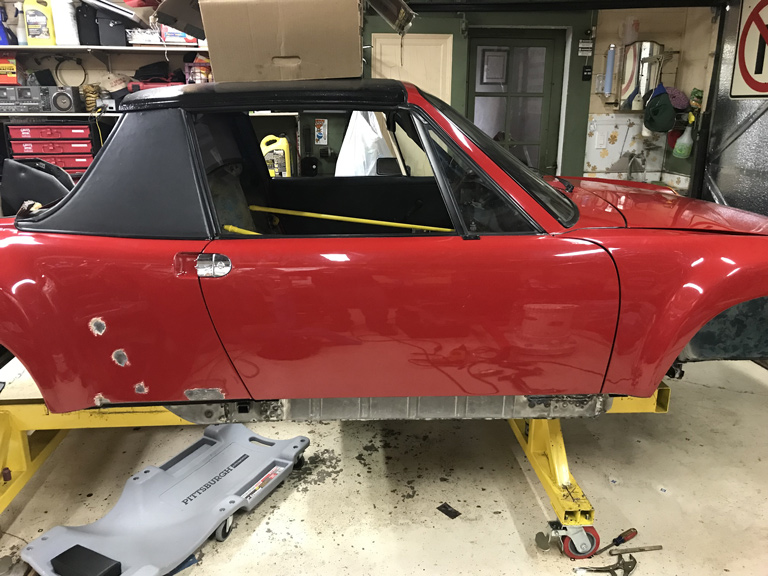
Passenger rear 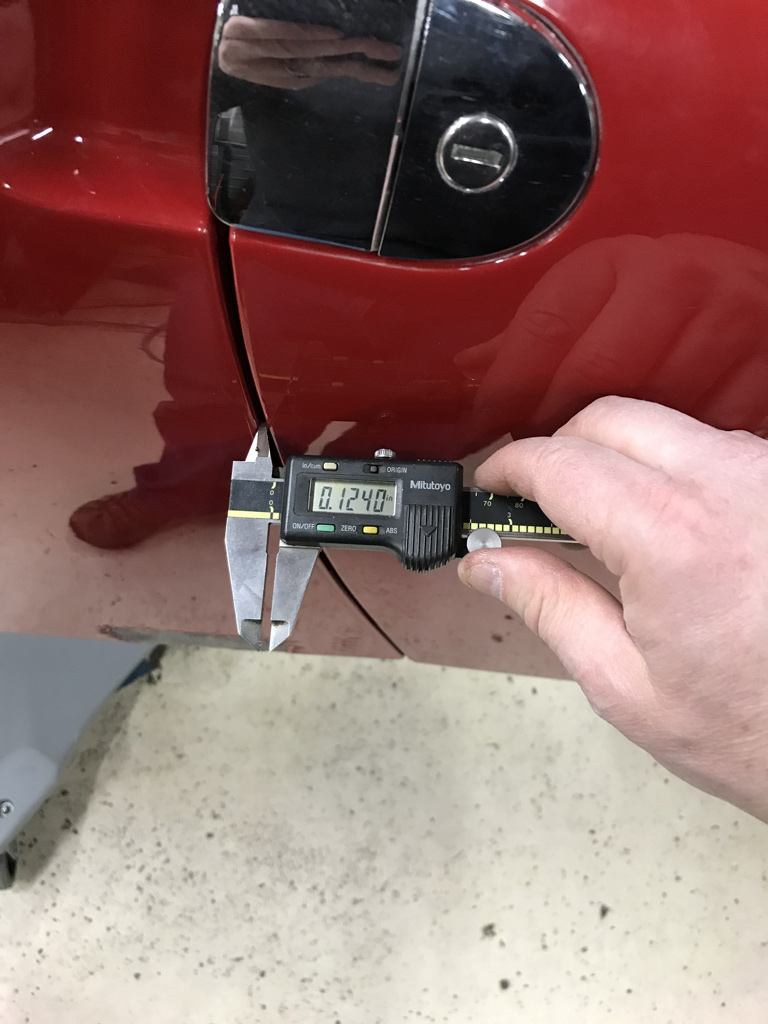
Passenger front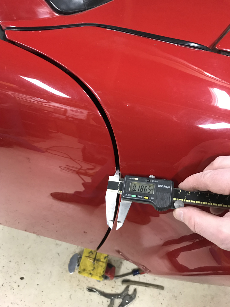
Driver rear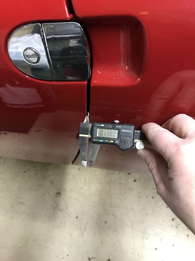
Driver front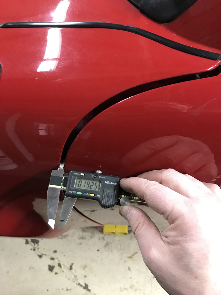
Posted by: Superhawk996 Apr 4 2020, 02:22 PM
I'm contemplating other solutions.
One might be to mill 1mm of the front of the door hinges to pull them forward about 1mm. I'm just worried this may have other implications for things like striker fits and/or fit of the triangular quarter window to the A-pillar.
1mm = 0.040" and doesn't sure seem like much but to me it looks like a country mile.
Other ideas?
Time to go work on another unrelated project before I do something unwarranted.
Posted by: tygaboy Apr 4 2020, 03:00 PM
OK, this may sound totally hack but...
I swapped my late doors for a set of early ones. The early ones are a little "longer" and I had what I felt looked like too tight a fit at the rear, particularly on the driver side.
WARNING: GRAPHIC CAR-NAGE follows! CWs and other purist-types may want to avoid this post!
So I took a 2x4 and small sledge hammer (I know, I know!), opened the door and bonked on the hinges, essentially driving the A pillar's hinge mounting surface forward until the front/rear door gaps sorta split the difference.
I also found that I could open the door just a bit and use it as a lever to set the door's up/down alignment to the body.
Stating the obvious: go slowly if you try this approach. I was surprised how easy it was to move the hinge area forward (and backward, if you go too far!)
I figured "Hey, these things are +/- 3mm so what's the big deal?"
What can I say, it worked for me. The doors open/close/latch and lock just fine.
YMMV.
Here's the best shot I currently have of how it turned out. Let me know if you'd rather I remove the pic.
Attached thumbnail(s)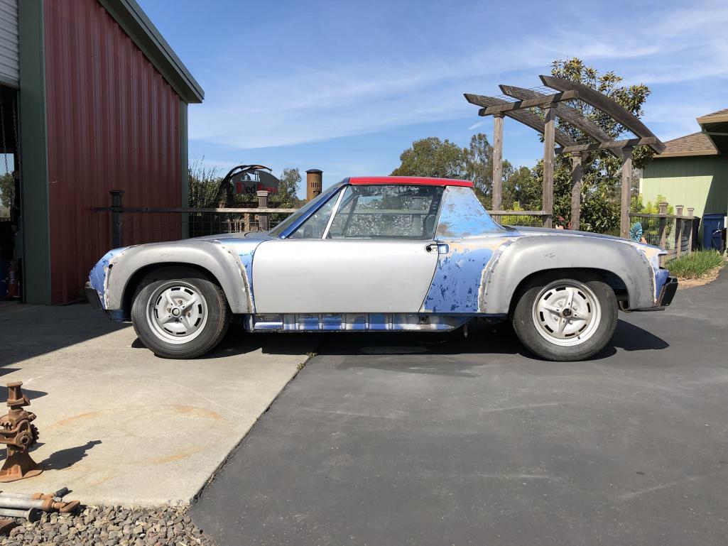
Posted by: Superhawk996 Apr 4 2020, 04:06 PM
@http://www.914world.com/bbs2/index.php?showuser=19241 .
Hmm. I sort of like the idea. I've definately reefed them up at the rear using the door as leverage to get the gap consistency I wanted.
When you did the "tweaking" did you just leave the door in place and hammer on the door hinge; bolts and all? Seems like that would be the way to go to do easy visual checks of the progress.
As another interesting tid bit, the passenger door on this car is an early doors - no impact bar and are clearly from another car (yellow on passenger side under the door trim).
I thought early and late doors had the same dimensions but differed only in impact bar and window regulator style. If that is true, that the early doors are a smidge longer that might help explain why the driver side door is a bit tighter at the rear too.
This car is an early build 73 - April and I know some early 73's had the earlier doors too so I never thought much of it other than that someone had swapped this door for sure and I haven't dug into the driver door to see what it is yet.
Posted by: mb911 Apr 4 2020, 04:14 PM
I agree with Chris .. You could also use a porta power to stretch it a bit.. My passenger front gap is not ideal.. I still have to work it through..
Posted by: mepstein Apr 4 2020, 04:22 PM
@http://www.914world.com/bbs2/index.php?showuser=19241 .
Hmm. I sort of like the idea. I've definately reefed them up at the rear using the door as leverage to get the gap consistency I wanted.
When you did the "tweaking" did you just leave the door in place and hammer on the door hinge; bolts and all? Seems like that would be the way to go to do easy visual checks of the progress.
As another interesting tid bit, the passenger door on this car is an early doors - no impact bar and are clearly from another car (yellow on passenger side under the door trim).
I thought early and late doors had the same dimensions but differed only in impact bar and window regulator style. If that is true, that the early doors are a smidge longer that might help explain why the driver side door is a bit tighter at the rear too.
This car is an early build 73 - April and I know some early 73's had the earlier doors too so I never thought much of it other than that someone had swapped this door for sure and I haven't dug into the driver door to see what it is yet.
I've never heard of early doors being longer.
Posted by: bbrock Apr 4 2020, 04:44 PM
WARNING: GRAPHIC CAR-NAGE follows! CWs and other purist-types may want to avoid this post!
The HORROR!!!!
 I can't believe you did that... but... that is exactly what I did. I had a door that was sagging plus an unacceptable wide gap that could not adjust out. After puzzling it over for a long time, I discover that the upper hinge post had indeed stretch from years of door weight and possibly a teenager or two leaning on an open door. So... Bang, bang, Maxwell's silver hammer came down upon its head... There is easily a mm of adjustment to be had there.
Posted by: tygaboy Apr 4 2020, 04:51 PM
I've never heard of early doors being longer.
@http://www.914world.com/bbs2/index.php?showuser=10825 - I didn't mean to imply they were, by design, longer than late doors, only that the set I have ended up being longer than the lates that were on the car. All within the usual tolerances for these cars. I suspect I just happen to end up with a set of each that may be on the inner/outer ranges.
Also, and this may have zero to do with any of this, but my suspension pickup mounting points measured way outside (longer) of the specs available on this site - see my build for details, if interested.
Posted by: mepstein Apr 4 2020, 04:55 PM
I've never heard of early doors being longer.
@http://www.914world.com/bbs2/index.php?showuser=10825 - I didn't mean to imply they were, by design, longer than late doors, only that the set I have ended up being longer than the lates that were on the car. All within the usual tolerances for these cars. I suspect I just happen to end up with a set of each that may be on the inner/outer ranges.
Also, and this may have zero to do with any of this, but my suspension pickup mounting points measured way outside (longer) of the specs available on this site - see my build for details, if interested.
Yea, the way these cars were made, I could see one line worker fitting it tight while another fit it loose and getting 1-5 mm difference in the final fit.
Posted by: tygaboy Apr 4 2020, 04:58 PM
@http://www.914world.com/bbs2/index.php?showuser=19241 .
When you did the "tweaking" did you just leave the door in place and hammer on the door hinge; bolts and all? Seems like that would be the way to go to do easy visual checks of the progress.
Yep, doors in place for the exact reason you mentioned. BAM, BAM, check. Repeat as needed.
Just watch the end of the piece of wood you use as the hinge bolts may chew it up and you just want to know what your pounding against.
Posted by: Superhawk996 Apr 6 2020, 08:03 AM
I haven't had a chance to bonk the doors yet though strangely I'm exited about the prospect of it. I would be such a simple & elegant solution.
I spent a little bit of time cleaning up the garage and working on couple other projects.
1st, as I was cleaning I passed by this gleaming gem. I had completely forgotten to thank @http://www.914world.com/bbs2/index.php?showuser=10825 for his generorsity in passing along this shining addtion to 2.4L six fan. I think this will be a spectacular accent piece when the fan gets painted or powdercoated. 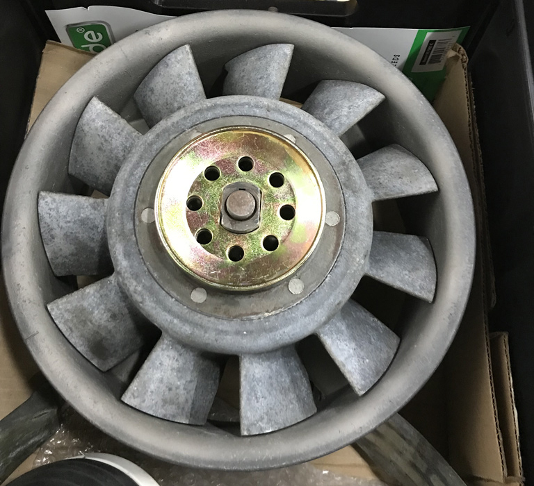
Posted by: Superhawk996 Apr 6 2020, 08:20 AM
I also spent some time working on engine tin.
Want to plead with those of you that have hacked up 2.0L passenger side tin from A/C installs, please don't toss it. It can be fixed and made to be perfectly serviceable.
If you have 2.0L passenger side hacked cylinder tin that you're contemplating scrapping feel free to send it my way!
Starting point: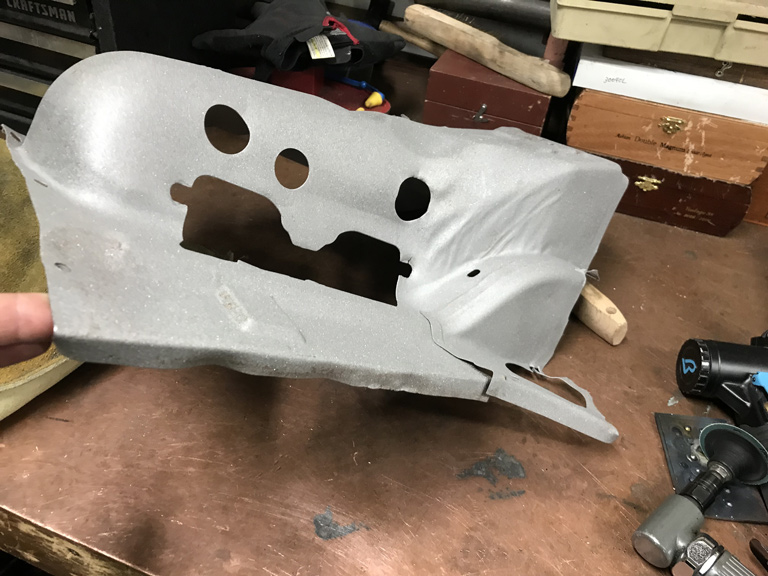
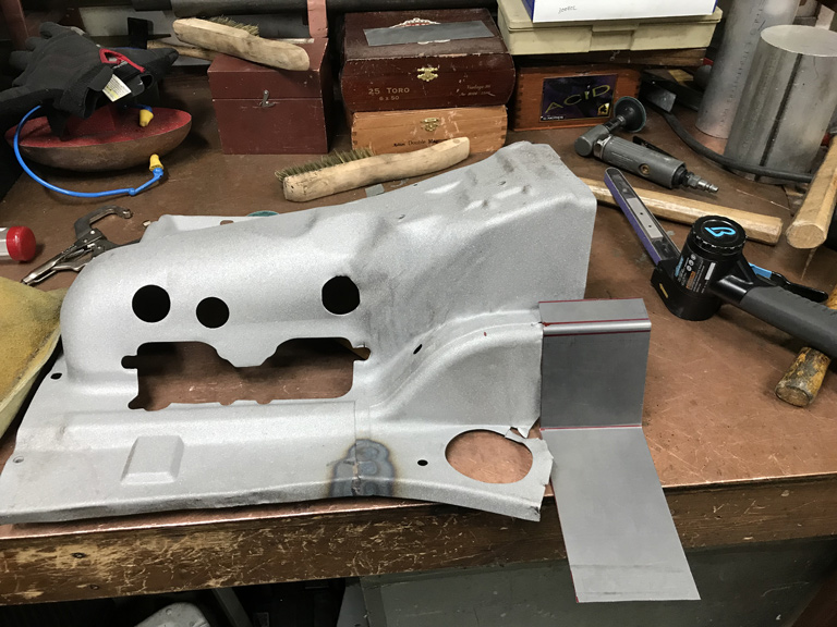
Finished serviceable tin: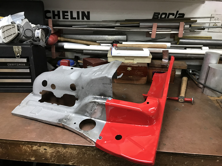
Posted by: bbrock Apr 6 2020, 08:56 AM
Nice work on that tin What is it about those six fans that make them so sexy?
Posted by: Superhawk996 Apr 6 2020, 09:22 AM
Nice work on that tin
What is it about those six fans that make them so sexy? @http://www.914world.com/bbs2/index.php?showuser=20845
Just like that special Marshal amp that Nigel Tufnel had. Insert best Spinal Tap imitation here . . .
It's that these go to 11 . . . See.

Not just 10 fan blades which anybody could do. . . but you see a Porsche fan has 11 blades.
Posted by: Superhawk996 Apr 7 2020, 07:56 AM
@http://www.914world.com/bbs2/index.php?showuser=19241
@http://www.914world.com/bbs2/index.php?showuser=20845
OK - So although I'm not a fan of bonking stuff with the BFH, I did make some progress but I hated every minute of it. It reminds me far too much or working on race cars under duress where expediency often trumps doing it right.
My bigggest hammer is about 5 lbs and I was seriously worried about missing the 2x4 and really Fuching up something else. Plus I'm old and frail and swinging a 5 lb hammer gets tiring really fast!
I gained about 0.020" or 0.5mm of movement and by that point I could see the hinge pillar sheetmetal starting to take on some deformation that I didn't like so I decided to call it quit's.
Overall, it looks much better to my eye than the overall picture does in the photo. If I'm still not happy later, I can always mill the door hinges another 0.020" and /or use some shim stock to tweak the fit's. In reality that won't likely happen until I get around to completely stripping this car back to return to original color of Alaska Blue Metallic. I personally despise red. Red cars have me cost thousands more in speeding tickets than other less eye catching color cars.
So here's the finished product. 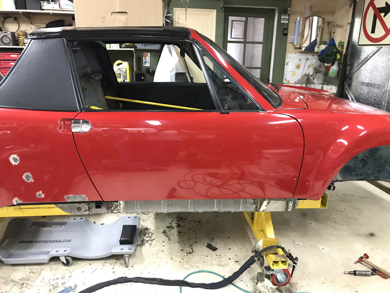
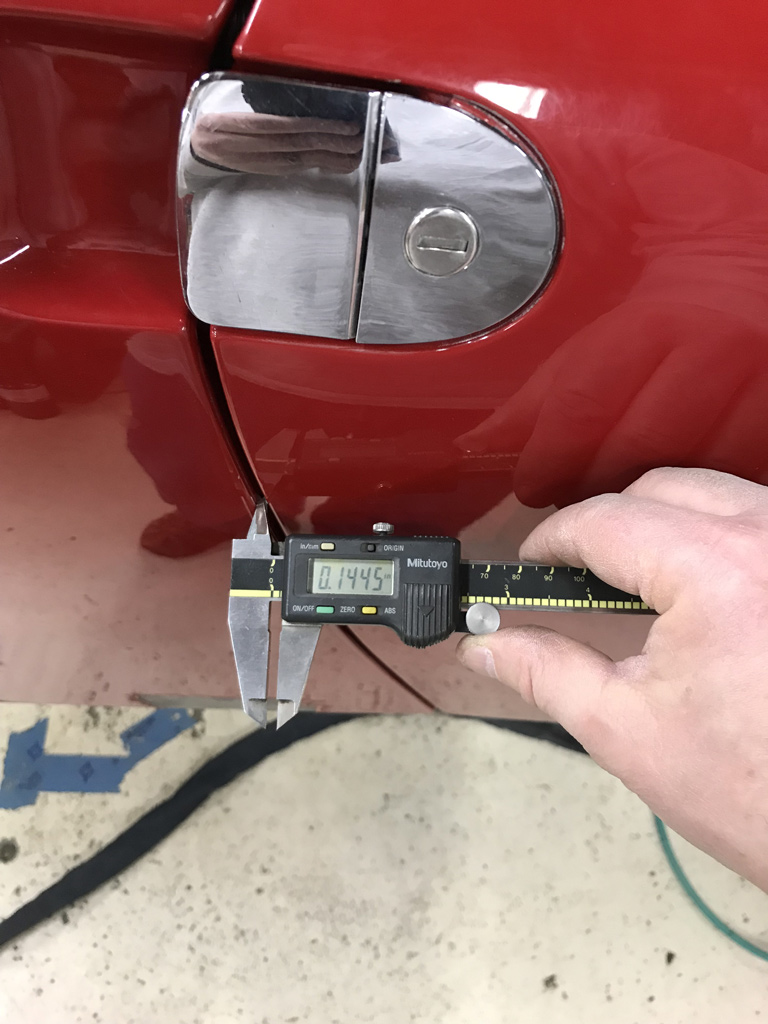
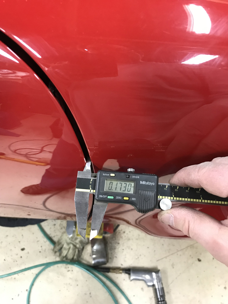
Posted by: bbrock Apr 7 2020, 08:02 AM
I would be happy with those gaps
Posted by: Superhawk996 Apr 7 2020, 08:08 AM
One of the other key projects for the day was to go out and hoard some Argon. My local gas supplier is one of the last in the area still open for business.
Now that I'm on forced vacation, I'm going though lots of gas and getting tired of having to stop to go exhange a tank. Now I have a spare on standby! 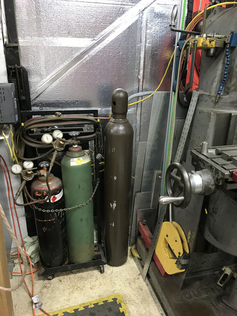
Having accomplished and after having tweaked the door fit, it was time to get the lower door post extension added that ties into the outer longitudinal. Fabrication of this little piece was way too time consuming. 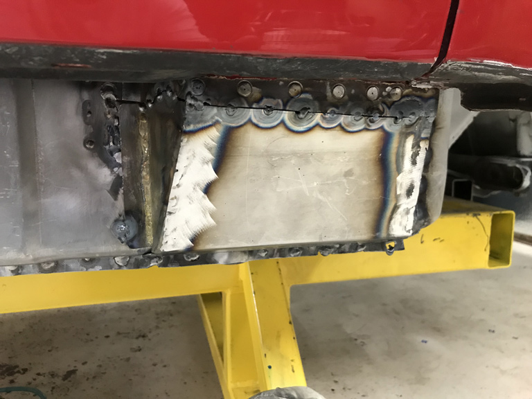
Most importantly, this piece had a couple of semi circular features that were used to fill in the remnants of previous AC damage left by a dealer turned loose with a hole saw 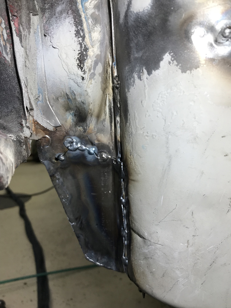
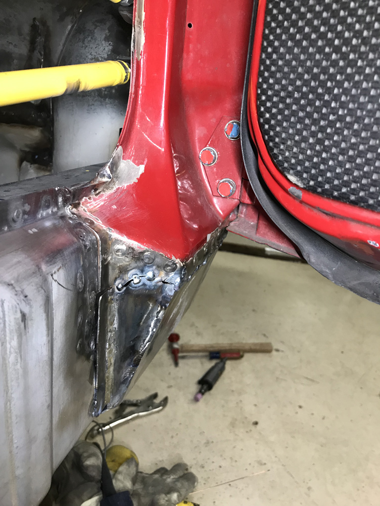
Posted by: tygaboy Apr 7 2020, 09:00 AM
I would be happy with those gaps
, big time. Nice work.Don't let perfect get in the way of really good.
(ask me how I know!)
Posted by: Superhawk996 Apr 7 2020, 11:54 AM
@http://www.914world.com/bbs2/index.php?showuser=20845
@http://www.914world.com/bbs2/index.php?showuser=19241
Thanks. That means a lot to me coming from you guys. Good enough to you = good enough to me and encourages me to keep moving forward rather than getting lost in 0.015" of door gap!
Posted by: euro911 Apr 7 2020, 12:50 PM
For some reason, some of us older guys have enough extra gas without having to run out and get more
Posted by: Superhawk996 Apr 8 2020, 09:49 AM
Started to prepare the rear bulkhead for new sheetmetal. Started by getting new panel holes for the snorkel and the speedo cable aligned to OEM sheetmetal. 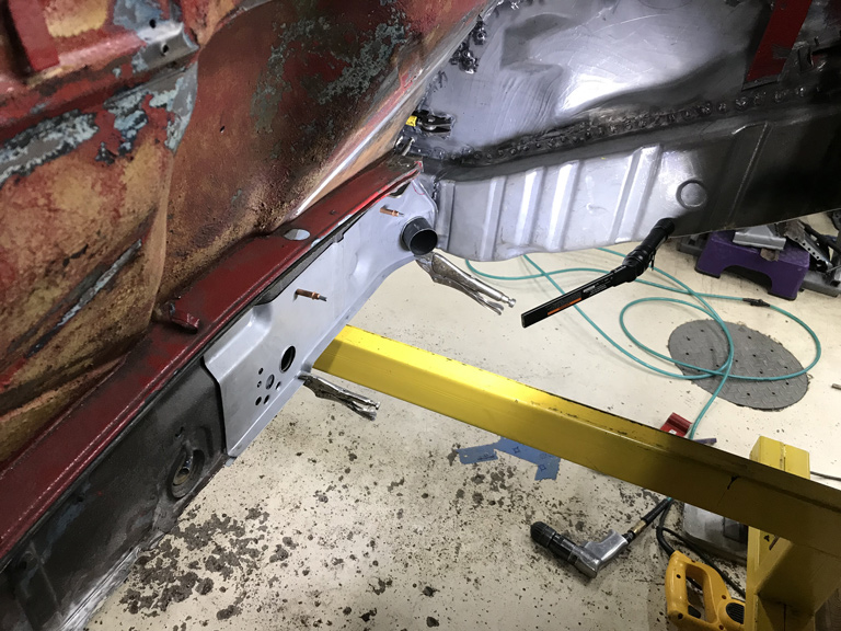
As usual, one thing leads to another. Needed to know how that outer bulkhead would fit to the inner bulkhead. And then of course since the inner bulkhead seemed too low, I needed to know how the new floorpan would fit.
After exhausting my supply of vice grips and welding clamps I had a temporary loose mockup. Turns out it all looks to be pretty straight forward and fits pretty darn well for repop sheetmetal. 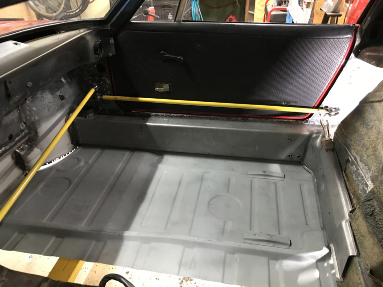
By then it was getting late, I was delerious, and after spending so much time in the hell hole, the sprayed on truck bed liner + the contact cement adhesive was grating on me.
Based on some pin holes that are on the interior passenger side that I had found when I had to cut out to access all of this work, I had a feeling that the driver side bulkhead was probably hiding some rust. Turns out I was right. That damn OEM engine pad that holds moisture had done its work. The driver side had some pretty heavy pitting and a few pin holes too. More metal work!
I was told this car was previously Florida car and owned by a body shop guy. I have found plenty of sand in the car so I suspect it may truly be a Florida car. Good body shop guy, well maybe not so much. Cheap body shop guy, maybe. I had an inclination that the spray on bedliner wasn't just there for noise deadning. I hate when people just try to cover over rust and pretend it isn't there.
After many hours of listening to the flail wheel and after going though a fresh $40 belt, I got most of the bulkhead stripped. That crap is tough and doesn't come off easily. If anyone has better suggestion to stripping bed liner I'm all ears! 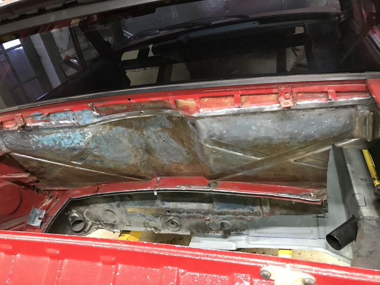
Posted by: kroelofsen Apr 8 2020, 12:02 PM
Hi I use citrus spray to remove that kind of gunk...
https://www.amazon.co.uk/Citrus-Based-Adhesive-Remover-MMM6041-3M/dp/B0006VPLKM
Posted by: Superhawk996 Apr 8 2020, 12:53 PM
Hi I use citrus spray to remove that kind of gunk...
https://www.amazon.co.uk/Citrus-Based-Adhesive-Remover-MMM6041-3M/dp/B0006VPLKM
@http://www.914world.com/bbs2/index.php?showuser=23255
Although that would work on the residual contact cement adhesive, I don't think it would even touch the spray on bed liner underneath a layer of paint.
If I'm mistaken, ping me back if you've sucessfully used it to remove spray on bed liner and how much of this stuff is needed.
Posted by: kroelofsen Apr 9 2020, 01:52 AM
Hi I use citrus spray to remove that kind of gunk...
https://www.amazon.co.uk/Citrus-Based-Adhesive-Remover-MMM6041-3M/dp/B0006VPLKM
@http://www.914world.com/bbs2/index.php?showuser=23255
Although that would work on the residual contact cement adhesive, I don't think it would even touch the spray on bed liner underneath a layer of paint.
If I'm mistaken, ping me back if you've sucessfully used it to remove spray on bed liner and how much of this stuff is needed.
Hi @http://www.914world.com/bbs2/index.php?showuser=22428 I used it to remove glue on the fire wall and to remove the undercoat in the wheel wells. It softens the under coat so it comes of more easy. It does not really touch paint although but it becomes dull...!
Posted by: djway Apr 9 2020, 03:01 AM
@http://www.914world.com/bbs2/index.php?showuser=19241
@http://www.914world.com/bbs2/index.php?showuser=20845
OK - So although I'm not a fan of bonking stuff with the BFH, I did make some progress but I hated every minute of it. It reminds me far too much or working on race cars under duress where expediency often trumps doing it right.
My bigggest hammer is about 5 lbs and I was seriously worried about missing the 2x4 and really Fuching up something else. Plus I'm old and frail and swinging a 5 lb hammer gets tiring really fast!
I gained about 0.020" or 0.5mm of movement and by that point I could see the hinge pillar sheetmetal starting to take on some deformation that I didn't like so I decided to call it quit's.
Overall, it looks much better to my eye than the overall picture does in the photo. If I'm still not happy later, I can always mill the door hinges another 0.020" and /or use some shim stock to tweak the fit's. In reality that won't likely happen until I get around to completely stripping this car back to return to original color of Alaska Blue Metallic. I personally despise red. Red cars have me cost thousands more in speeding tickets than other less eye catching color cars.
So here's the finished product.
If the door if functioning correctly and it is just the gap, which were bad from the factory on many cars, one trick is to weld on some welding rod to the leading edge then file to shape.
Posted by: Superhawk996 Apr 19 2020, 08:03 AM
Been a few weeks since I've posted. So many other things compete for garage time.
My wife has been insisting that I trim the "new" dog's hair since the dog groomers are no longer open. The important thing to understand is that I love dogs and that this is the Mother-In-Law dog that we are looking after while she is in assisted living.
I've grown up with Labradors. Very low maintenance dogs. The idea that I'd have to spend more to get a dog a haircut than I spend to cut my own haircuts just doesn't seem right.
Well, it just so happens that Amazon sells a set of dog clippers. How hard could it be?
Turns out not terribly hard. Mission accomplished. 
Posted by: Superhawk996 Apr 19 2020, 08:14 AM
On the garage front, lots of time spent on things that will never be seen, or appreciated later on.
Added a doubler to the inner longitudinal transition. Not so much becuase I think it was absolutely necessary Porsche did a good job of staggering the joints but more so for my own piece of mind. 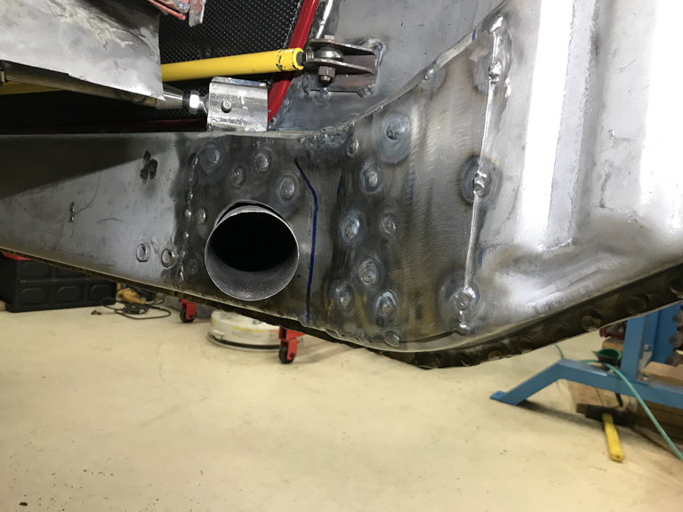
As it turns out, this might not have been a great move. Up until now I've been constantly checking my X & Y suspension pickup point locations and things were peachy. So yesterday just as a sanity check before moving on, I put the Z gauge back in place to check.
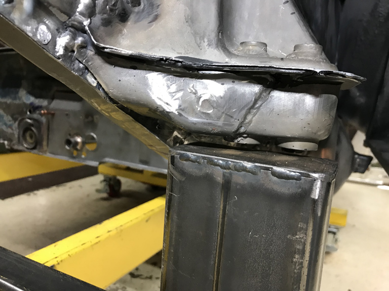
I now have a 6mm height change in Z! FUCH!
Now I'm trying to figure out the next step.
1) Leave as is. Add another 6mm of caster shim as needed later on.
2) Try to create a fixture to "pull" this back down and then I could heat the "frame" sections with a rosebud torch to stress relieve it and hopefully get it to settle back to where it should be.
Option 2 comes with the concern that my body dolly really isn't intended to be a Cellete that can stand up to body pulls. I'm very concerned that I'd have to double up my body dolly longitudinal member to prevent it from deforming as I pull down on the suspension console. Time to think about this carefully.
I will be doing yet another complete round of measurement on all suspension pick up points just to make absolutely sure that Z height is the only thing that moved.
Posted by: Superhawk996 Apr 19 2020, 08:22 AM
Fuming from having discoverd the suspension console FUBAR I took out some agression by stripping the rest of the hell hole shelf. 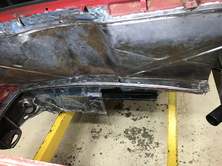
I then tried to distract myself for the remainder of the evening by prepping the lower bulkhead.
This car is crazy. Much of the lower 1" of the floorpan to anything is terribly rusted. But above that 1" line, things are pretty solid.
Case in point, here is the Speedometer cable tube after being removed from the original sheetmetal and blasted. Rock Solid. 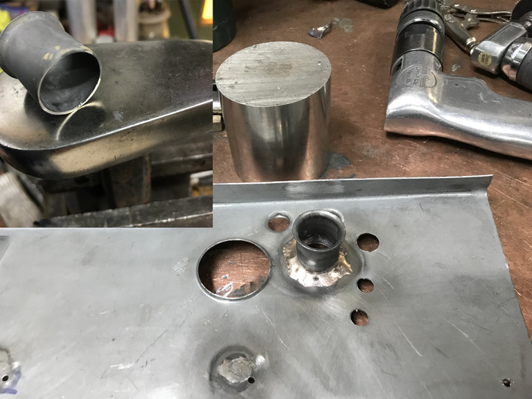
Brazed it to the replacement sheetmetal with some silicon bronze TIG filler.
Posted by: bbrock Apr 19 2020, 09:06 AM
I now have a 6mm height change in Z! FUCH!
Now I'm trying to figure out the next step.
1) Leave as is. Add another 6mm of caster shim as needed later on.
2) Try to create a fixture to "pull" this back down and then I could heat the "frame" sections with a rosebud torch to stress relieve it and hopefully get it to settle back to where it should be.
Option 2 comes with the concern that my body dolly really isn't intended to be a Cellete that can stand up to body pulls. I'm very concerned that I'd have to double up my body dolly longitudinal member to prevent it from deforming as I pull down on the suspension console.
Time to think about this carefully.I will be doing yet another complete round of measurement on all suspension pick up points just to make absolutely sure that Z height is the only thing that moved.
Oh man. That sucks. What about just cutting off the suspension console and repositioning to the correct geometry location?
Nice job on the hair cut!
Posted by: Superhawk996 Apr 19 2020, 11:33 AM
Oh man. That sucks. What about just cutting off the suspension console and repositioning to the correct geometry location?
@http://www.914world.com/bbs2/index.php?showuser=20845
Entertained that for about 0.5 seconds.
That thing was already swiss cheese when I took it off the 1st time. After all the puddle welds the swiss cheese holes will be even larger. The other thing is that I've tried to execute this whole excercise without cutting my rear quater panel or the door jamb. I have esentially built the "frame" and suspension structure from the outside inward.
Access to the front to the supension console for cutting puddle welds and/or to re-weld is non existant.
I've got to admit at this point that tribal wisdom about cutting the quarter and/or door jamb appears to be the better path than the one I've taken by trying to preserve the paint.
The new option crossing my mind is leave as-is. Mill a 6mm offset plate. Use as temporary solution. In future years I intend to strip all to bare metal, fix front quarter prior accident damage with lap welds and the shady trunk floorpan. At that time, I could put it on a Celette and have it pulled properly. Not ideal, but, I'm trying to prevent myself from getting too hung up on this as I contemplate solutions.
Still cleaning up the floor and getting ready to lay down new measurement points to insure X & Y dimensions haven't changed.
Need more think time. Open to alternatives like you've mentioned though if anyone else has experience recovering from a fiasco like this.
Posted by: mbseto Apr 19 2020, 01:37 PM
Your rear fender looks like it has bullet holes. Something you're not telling us?
Posted by: Superhawk996 Apr 19 2020, 01:43 PM
Your rear fender looks like it has bullet holes. Something you're not telling us?
I live in Detroit Metro area. Should be self explantory.
That is the other part of why I should have just cut the rear quarter panel. In the process of trying to preserve the quarter panel paint, I decided to do this repair from the inside.
As I was
the frame initially, the sawzall blade hit the rear quarter several times from the inside, chipping the paint and raising a dent. So for all my best efforts, that quarter still needs some touch up. Not so bright on my part. It was mentioned early on in my thread but there are a bunch of pages there so I'm sure others are wondering the same thing. With the wisdom of hindsight this probably wasn't the best way to approach the work.
Posted by: euro911 Apr 19 2020, 02:07 PM
Posted by: Superhawk996 Apr 19 2020, 05:26 PM
Well after two rounds of measurement this afternoon, no change in the X or Y dimensions and the suspension points are still square to each other. Whew!
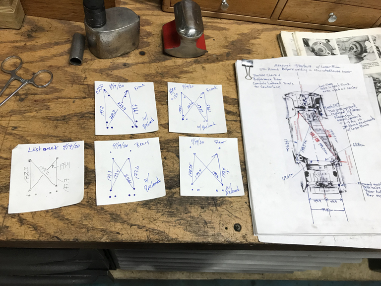
Adding an extra 6mm spacer is a lot easier to deal with than if the XY coordinates had shifted. At least it shifted up. That would give more negative camber which can be dialed out with shims. If it had shifed down in Z that would way worse and could result in postive camber with no way to dial it back toward negative camber! For the moment I'll be happy for this little gift.
For now I'm going to leave Z height alone. Need more time to think about how this could have shifted purely in Z direction.
Posted by: Superhawk996 Apr 25 2020, 03:36 PM
As usual, tools need fixin' before you can do actual work.
Air compressor has been running a really high duty cycle over the last couple years. Time to change the oil and the air filter.
Air filter is a little bit less than a manly size. Hard to belive this is all there is for filtration. Oh, well as long as it keeps working.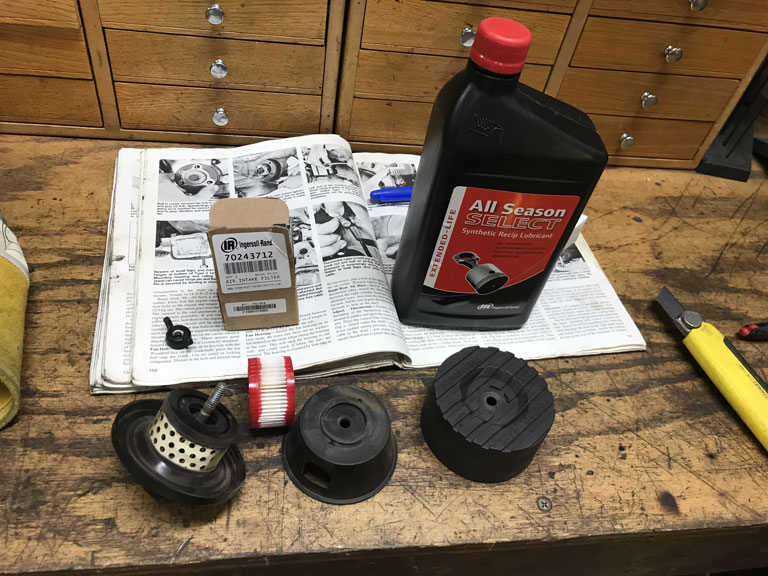
With that task buttoned up it's time to 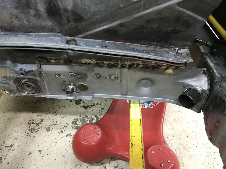
Posted by: Superhawk996 Apr 28 2020, 07:03 AM
Finally, not only is the front attached to the rear, the passenger long is now tied cross car too! 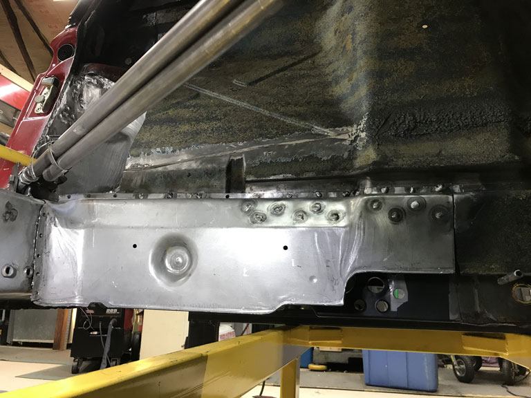
So here's the disaster of the week. This portion of the rear bulkhead welds over a U shaped channel that acts as the structure for the bulkhead and support for the 6 cylinder engine mount.
Wouldn't you know it, but even though I had the vertical rib lined up perfectly when it was tacked, when I laid in the final weld bead, it shrunk inward. This caused the panel to tip in at the top. The nature of the vertical stiffening bead makes it stand out even more and it looks like
Honestly, I'm not sure how to prevent this when having to weld thin sheet metal to what was effectely a much thinker structural element. I've done this in the past with a better degree of success but in this case, it tipped in way more than I anticipated and the more I tried to "fix" it, the worse it got. At this point I think the only "fix" is to cut the weld across the bead, and then use a slide hammer to pull it out. I don't think the fix is worth it given that this area really isn't seen. Have some time to think about that one. 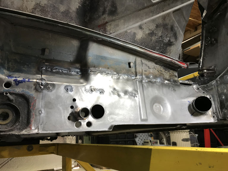
Certainly not the end of the world, but not really craftsmanship that I can be proud of.
Posted by: Superhawk996 Apr 28 2020, 07:08 AM
With the bulkhead attached to the long, I turned my attention toward wanting to mock up the tunnel.
I have a donor tunnel but it needs quite a bit of work before I can even get to the point of a mock up.
Stripped the tar.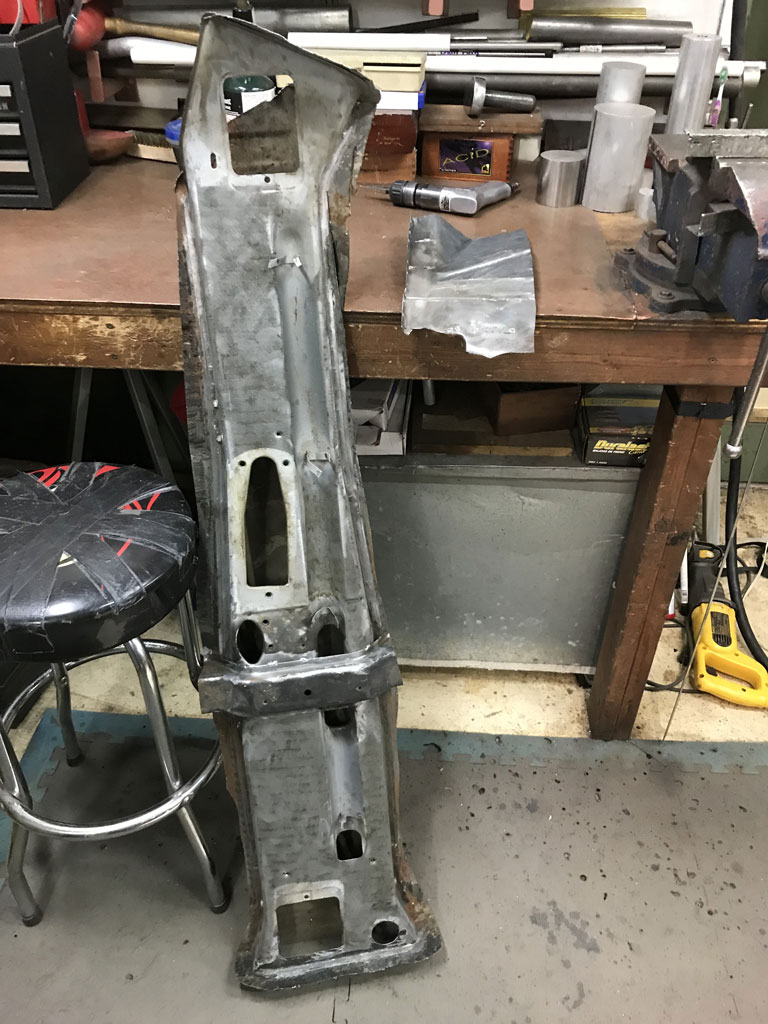
Spent a couple of solid hours drilling about 100 spot welds. I'll post some pictures of the tunnel internals once I get the last of the MIG welds cut and the tunnel split wide open. 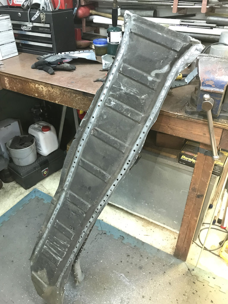
This tunnel had a broken clutch cable tube that was repaired with some bolted in hooks. It will be worth seeing the fix from the inside for those that may be struggling with broken clutch tubes. After that I'll have to source the metric size tubes from RD and then rebuild the tunnel internals.
Posted by: bbrock Apr 28 2020, 07:42 AM
Certainly not the end of the world, but not really craftsmanship that I can be proud of.
If you can figure out a way to pull that out enough to make it an outie rather than innie, a shrinking disc could work miracles to straighten that out after grinding down the welds. That's how I dealt with similar troughs left after welding my rear quarter panels back on. Too bad that spot is double-walled.
Posted by: Superhawk996 Apr 28 2020, 08:11 AM
Hmm. Maybe, but I think the main issue with attempting the shrinking disc is two fold.
1) the vertical bead. Shrinking usually works for large less crowned surfaces.
2) The thing that sucked the bead in is the U shaped structure behind it. As that puddle weld cools, it pull the non structural sheet metal toward the stiffer cooler U channel behind it.
might not hurt.
What I tried to do was to shink the panel back toward the sheetmetal with a little TIG torch heat. What it did was exactly the opposite. It actually sucked it toward the U channel.
If only I hadn't welded the interior side panel completely first. Then I could have had easy access to the back side of that panel and I could probably have bumped out the lip of the U channel.
Posted by: bbrock Apr 28 2020, 08:35 AM
Hmm. Maybe, but I think the main issue with attempting the shrinking disc is two fold.
1) the vertical bead. Shrinking usually works for large less crowned surfaces.
2) The thing that sucked the bead in is the U shaped structure behind it. As that puddle weld cools, it pull the non structural sheet metal toward the stiffer cooler U channel behind it.
might not hurt.
What I tried to do was to shink the panel back toward the sheetmetal with a little TIG torch heat. What it did was exactly the opposite. It actually sucked it toward the U channel.
If only I hadn't welded the interior side panel completely first.
Then I could have had easy access to the back side of that panel and I could probably have bumped out the lip of the U channel. Ah! I forgot about it being "glued" to the U-channel. And yes, the bead wouldn't allow it to go perfect like you might get on a flat panel, but I had a patch on the inner firewall where the disc pulled a beaded area flat enough that a thin skim of reinforced filler could smooth it over. That U-channel is the killer though. Bummer.
Posted by: Superhawk996 Apr 28 2020, 02:30 PM
Parts for the 2.4L six finally came back home from thier winter vacation in AZ at Ollies.
Just did a quick initial unpacking is encouraging. Case has cleaned up nicely after a media tumble. Has that nice grey magnesium look! 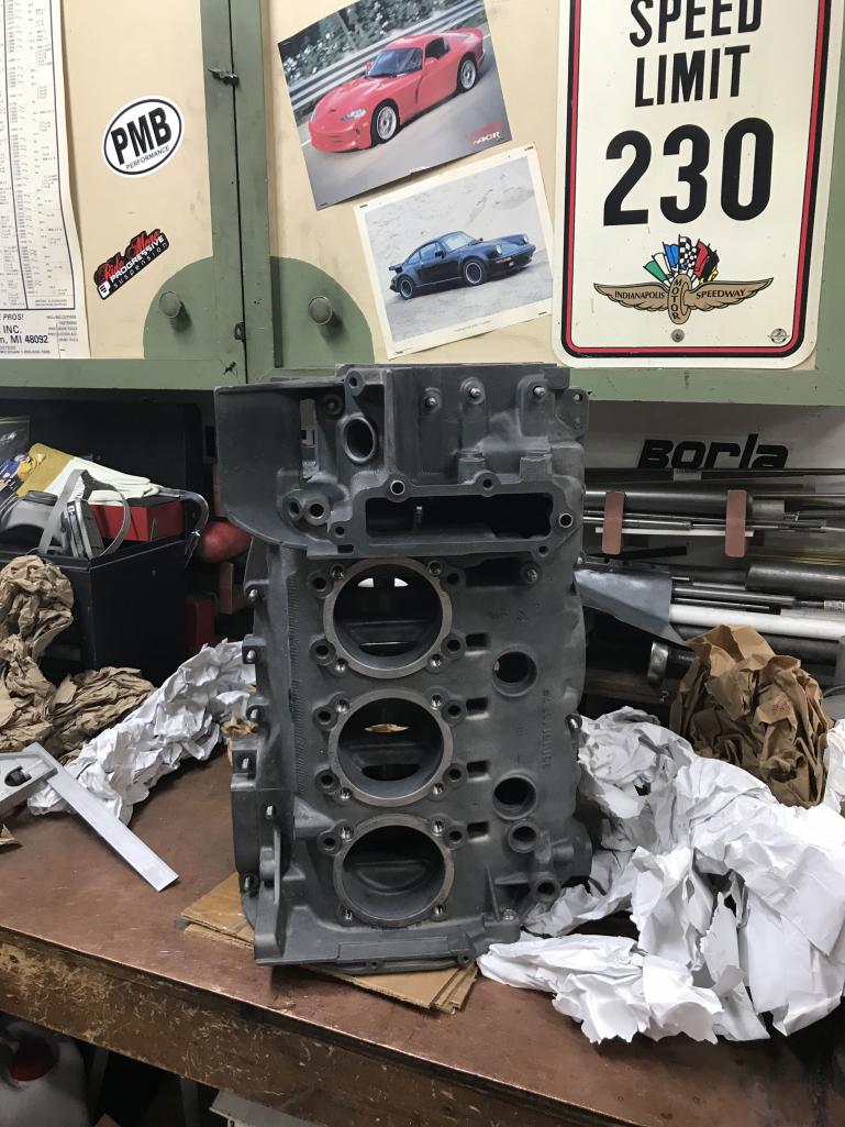
The engine mounting boss that cracked has been repaired very nicely. 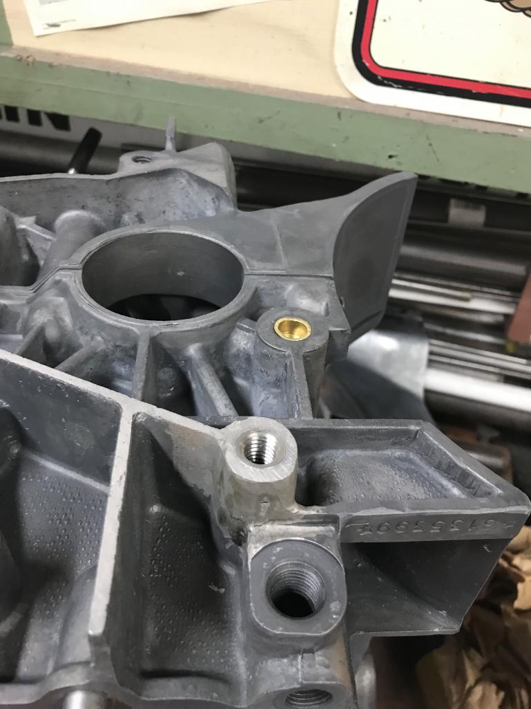
More unpacking still to be done. Will post some more pictures later of macining done to main bearings and addition of shuffle pins, etc.
Now the problem is these parts go on the back burner until I figure out whether or not I have a job due to the ongoing panicdemic.
Posted by: Superhawk996 Apr 28 2020, 05:36 PM
Here's a comparison of the bearing web that was a little bit compromised by porosity.
Before:
After: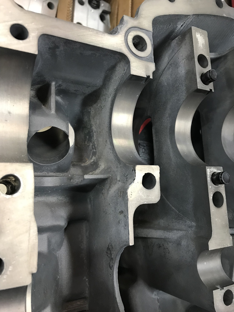
Posted by: Superhawk996 Apr 28 2020, 05:41 PM
Main Bearing Saddle with porosity
Before: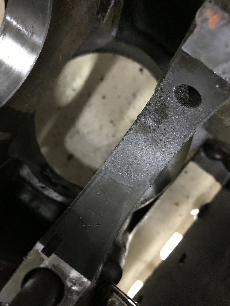
After line bore to standard bearing size: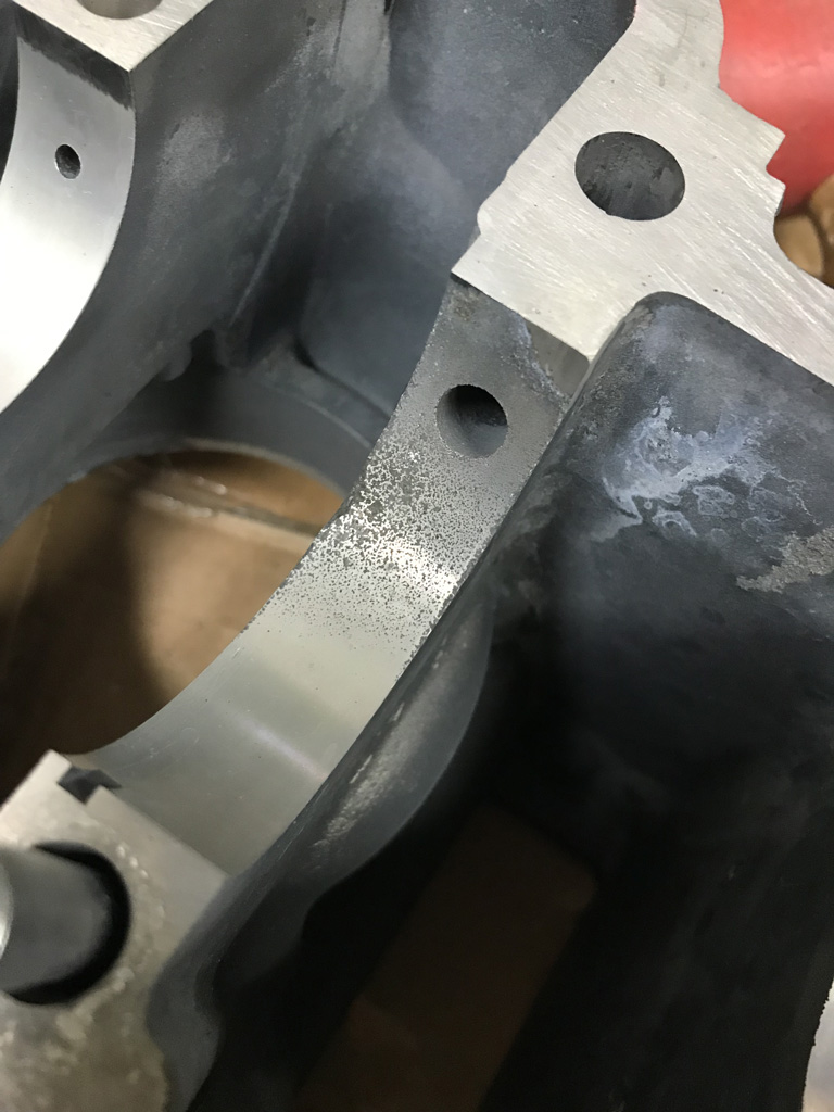
I'm very happy with the clean up on this main bearing saddle. Perfection was out of the question. In the end the bearing is well supported and the really crunch looking porosity is gone.
Posted by: Superhawk996 Apr 28 2020, 05:49 PM
Overall the case was updated with shuffle pins, the oil bypass modification, addition of case savers to all cylinder studs, cylinder decks were machined, and of course new case studs all around. 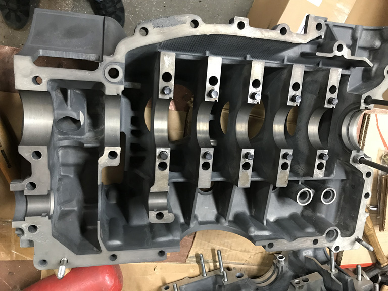
I'm pretty sure the shuffle pins are overkill for a street engine that will get built to E spec, but once this is put together, I wanted the case to outlive me.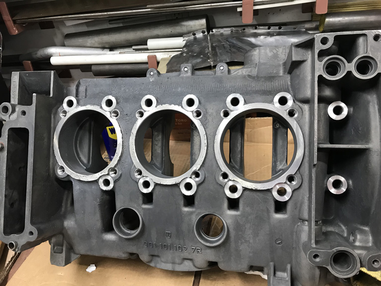
Posted by: Superhawk996 Apr 28 2020, 05:59 PM
Heads turned out great. Amazing what a good hot tank and media tumble can do for making parts look new again. 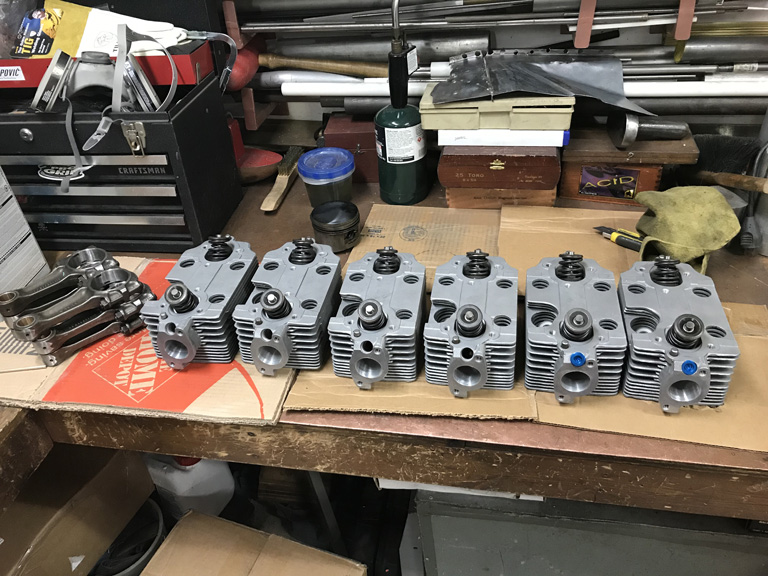
Heads were ported to 34mm to work with PMO ITB's.
Since I found a bent valve and a cracked valve retainer at teardown, these are completely new valves, guides, springs, guide seals, and then the heads were surfaced.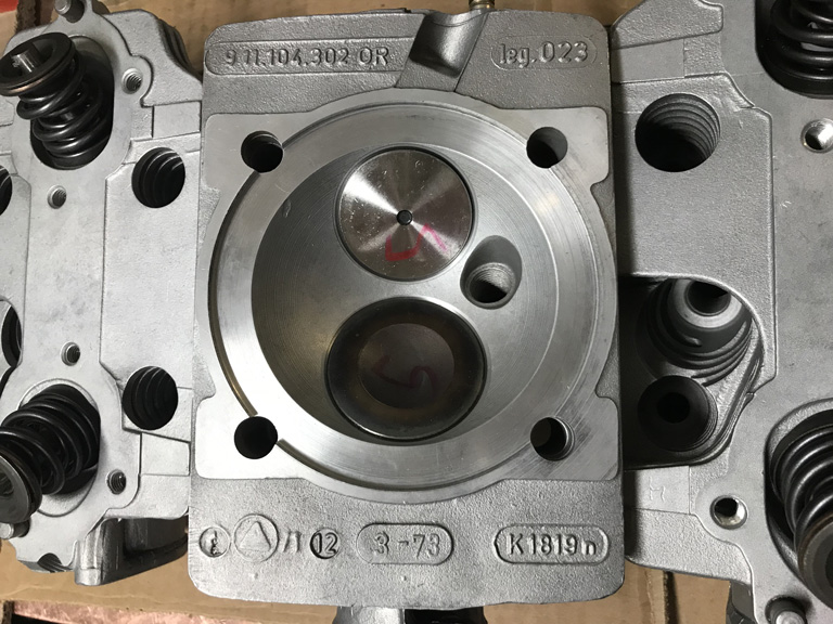
And of course, the rods were also had the small end bushings replaced and the big ends were resized.
Posted by: Superhawk996 Apr 28 2020, 06:21 PM
The big waste of time and money in this whole excercise was $140 spent trying to clean the oil cooler. Ollies spent a bunch of time getting it cleaned out but then it failed pressure testing. Unfortunatly they didn't mark where it was leaking. Trying to fix it is a non-starter since I don't feel like building up a fixture to pressure test it.
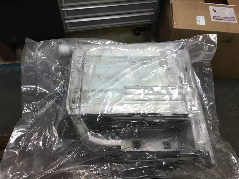
could be worse.
I started having second thoughts about cleaning it anyway. I hate reusing an oil cooler from an engine that I don't know the history of. It's always a little be hard to be sure that there isn't some schrapnel sitting in there just waiting to come out and destroy a new engine.
The main drawback was that 911 engine coolers are so pricey it seemed like it might be worth the gamble if this one were to come back cleaned and pressure tested.
Probably a sign that I was being foolish to use an old cooler on a fresh rebuild.
Posted by: mepstein Apr 28 2020, 07:17 PM
We would reuse a cooler out of a running engine but not one that was from a broken engine. I used the Stompski gauge to pressure check. If it failed, the cooler got tossed. Past experience was if a cooler had one leak and was fixed, it would shortly develop another. Are you doing a front cooler? If so, ditch the engine cooler and just use the front one.
Posted by: Superhawk996 Apr 29 2020, 05:49 AM
Past experience was if a cooler had one leak and was fixed, it would shortly develop another. Are you doing a front cooler? If so, ditch the engine cooler and just use the front one.
@http://www.914world.com/bbs2/index.php?showuser=10825
Thanks for sharing that learning from your shop. Makes sense. If something like an oil cooler weld has fatigued, even though you fix the one spot, there are likely to be more sports right in the vicinity that are on the verge of going bad.
Sort of the same thing I do with headlamps and tail lamps. When I replace them, I do it in pairs. Personal experience is roughly similar. By the time one reaches end of life, the other certainly isn't much further behind.
No front cooler for me so I'll eventually spring for a new engine cooler once I get this engine project back on track.
Posted by: porschetub Apr 29 2020, 08:51 PM
The big waste of time and money in this whole excercise was $140 spent trying to clean the oil cooler. Ollies spent a bunch of time getting it cleaned out but then it failed pressure testing. Unfortunatly they didn't mark where it was leaking. Trying to fix it is a non-starter since I don't feel like building up a fixture to pressure test it.
could be worse. I started having second thoughts about cleaning it anyway. I hate reusing an oil cooler from an engine that I don't know the history of. It's always a little be hard to be sure that there isn't some schrapnel sitting in there just waiting to come out and destroy a new engine.
The main drawback was that 911 engine coolers are so pricey it seemed like it might be worth the gamble if this one were to come back cleaned and pressure tested.
Probably a sign that I was being foolish to use an old cooler on a fresh rebuild.
Strange practice doing it that way?,pressure test always comes first,have been through all the 911 cooler BS,had one fail with a steady drip,had to buy a replacement in my country that was $$$$,tested ok and washed it in solvent for several days ,SO much crap came out then got it ultrasonically cleaned (more crap)and then got a local alloy guru to weld on the angled oil fitting...really a hassle as the PO said the 914-6 cooler he supplied was fine
.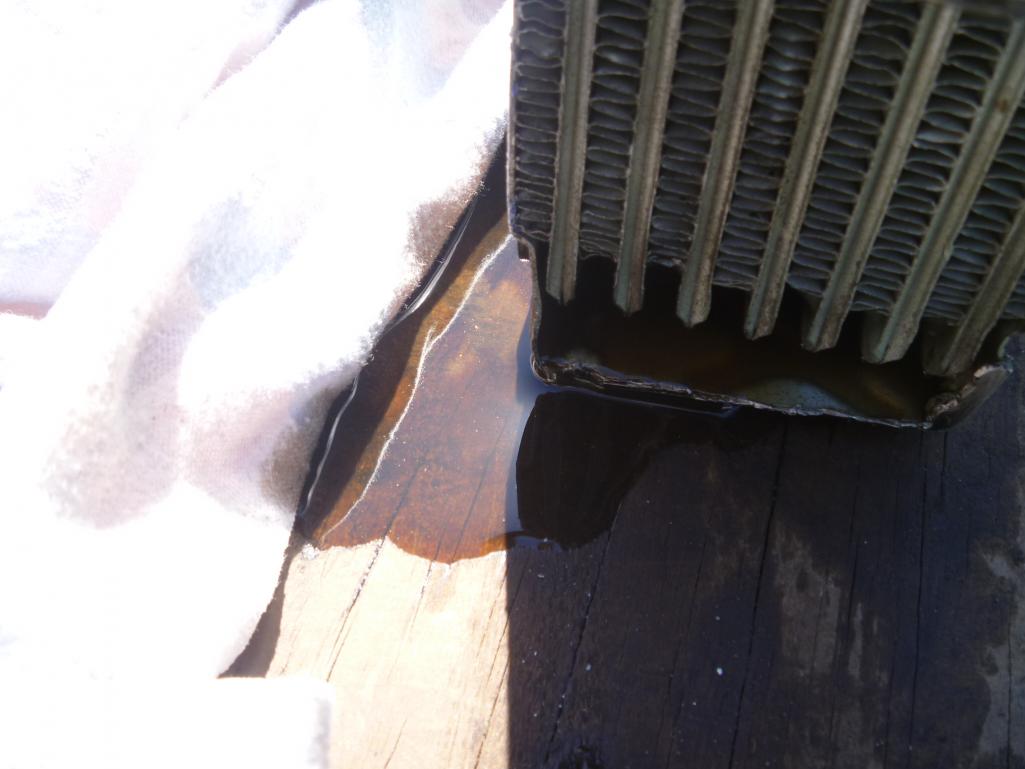
Pic shows old cooler with 20 psi on it,IMO in the 911 motor with a good oil pump they can reach high pressure on first startup with cold oil,a used cooler can be a gamble but my replacement has been fine.
Posted by: Superhawk996 Apr 30 2020, 06:07 AM
@http://www.914world.com/bbs2/index.php?showuser=18995
Sorry you had so much trouble too. Coolers are a PITA that is why I've always just replaced them as standard practice on Type 1 and Type 4 rebuilds I've done. I know Ollies went though several versions of clean and test. I'm not sure I ever got the full story. All I know for sure is that it wasn't clean like this when it went away, so they definately spent some time trying to save it.
They said initially there was some sort of blockage that kept coming out of the ultrasonic tank as black stuff. I'd be willing to bet they tested 1st but with some sort of blockage it could have passed pressure test 1st and then failed later once they got the blockage cleared?
Glad you got your cooler issued under control. Those leaks don't look fun at all.
I've seen a number of 914/6 coolers pass though FS/WTB but I can't bring myself to pay that kind of money for a cooler that I have no idea where its been. . . . though that philosophy wasn't in practice back in my younger dating years. At this point I'd prefer a virgin cooler. However, that expense of a new cooler will be put off until the panicdemic subsides and my job situation is a known entitiy.
Posted by: mb911 Apr 30 2020, 06:36 AM
I can tell you from personal experience the new coolers are not as near nice as the original.. From a quality stand point.
Just did a mod the other day for someone.. This was used and clean but very nice.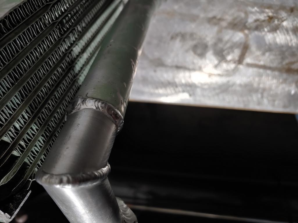
Posted by: FourBlades Apr 30 2020, 10:41 AM
Engine is looking great!
That should last a long time.
Getting a new cooler will be worth it just for not worrying about debris from the old one.
Can't wait to see this car on the road!
John
Posted by: Superhawk996 Apr 30 2020, 11:02 AM
Engine is looking great!
That should last a long time.
Getting a new cooler will be worth it just for not worrying about debris from the old one.
Can't wait to see this car on the road!
John
@http://www.914world.com/bbs2/index.php?showuser=8414
Thanks John! It's such a long slog starting with a car that should have been scrapped. The encouragement from the forum certainly helps keep me motivated.
Work in the short term will consist of the "free" work to fix the rust and replace the sheetmetal which was paid for over a year ago. No worries there.
Likewise I have enough already paid for parts to put together one of the 2.0L four cyclinders in my posession at the moment. So the engine work is "free" at this point.
Luckily I'm still working for now which is great. However, I don't know for how much longer as the L word is being rumored. The only upside to a layoff would be having time to work on the car with the parts that were previously paid for and sitting on hand.
At this point, based on slow progress to date, I'm shooting to be on road next summer. More time on my hands would pull that forward substantially.
Posted by: mb911 Apr 30 2020, 11:29 AM
Engine is looking great!
That should last a long time.
Getting a new cooler will be worth it just for not worrying about debris from the old one.
Can't wait to see this car on the road!
John
@http://www.914world.com/bbs2/index.php?showuser=8414
Thanks John! It's such a long slog starting with a car that should have been scrapped. The encouragement from the forum certainly helps keep me motivated.
Work in the short term will consist of the "free" work to fix the rust and replace the sheetmetal which was paid for over a year ago. No worries there.
Likewise I have enough already paid for parts to put together one of the 2.0L four cyclinders in my posession at the moment. So the engine work is "free" at this point.
Luckily I'm still working for now which is great. However, I don't know for how much longer as the L word is being rumored. The only upside to a layoff would be having time to work on the car with the parts that were previously paid for and sitting on hand.
At this point, based on slow progress to date, I'm shooting to be on road next summer. More time on my hands would pull that forward substantially.
@http://www.914world.com/bbs2/index.php?showuser=22428 I hear you.. I have made amazing progress on my car as I have not been working much and not many people buying parts so lots of free time.
Posted by: Superhawk996 May 3 2020, 12:20 PM
As promised, tunnel internals exposed. 
This donor tunnel has a previous clutch tube repair made with a coule of threaded J-hooks. Overall, one of the cleaner repairs i've seen when this breaks loose. 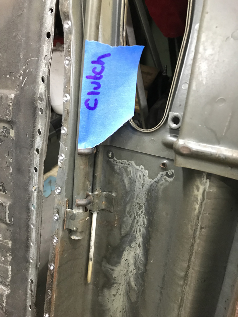
However the mid-tunnel support braket also has been fatigued and cracked. It's hard to say which end broke 1st and which failure led to the other. 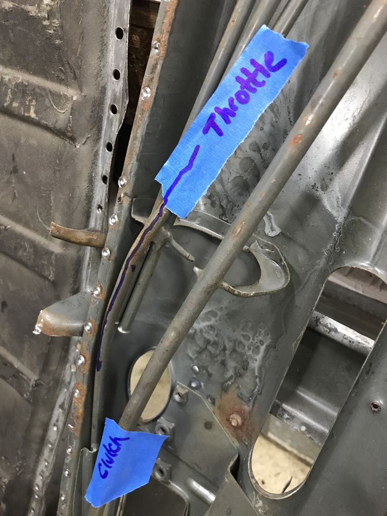
When I rebuild the tubes inside this tunnel, I'll do a little bit more reinfocement to make sure this doesn't happen again.
Posted by: Superhawk996 May 3 2020, 12:26 PM
I hear you.. I have made amazing progress on my car as I have not been working much and not many people buying parts so lots of free time.
@http://www.914world.com/bbs2/index.php?showuser=9892
It is a catch 22 isn't it? Age old truth. You can have time or you can have money. It is rare to have both at the same time.
Hopefully this crisis of fear will pass soon. Lot's of innocent folks that just want to make a living out there being harmed by all of this nonsense and thier inability to simply earn a living for themselves and thier family. That way we can all get back to buying those awesome parts from you
. Posted by: mb911 May 3 2020, 04:39 PM
I hear you.. I have made amazing progress on my car as I have not been working much and not many people buying parts so lots of free time.
@http://www.914world.com/bbs2/index.php?showuser=9892
It is a catch 22 isn't it? Age old truth. You can have time or you can have money. It is rare to have both at the same time.
Hopefully this crisis of fear will pass soon. Lot's of innocent folks that just want to make a living out there being harmed by all of this nonsense and thier inability to simply earn a living for themselves and thier family. That way we can all get back to buying those awesome parts from you
.Thanks for your support.. As you know not getting rich here but it fuels my habit.. Did make progress though again.. Almost have a runnner..
Posted by: Superhawk996 May 3 2020, 04:52 PM
Thanks for your support.. As you know not getting rich here but it fuels my habit.. Did make progress though again.. Almost have a runnner..
@http://www.914world.com/bbs2/index.php?showuser=9892
I watched the YouTube from the walkaround a Saturday or two ago -- Car looks great. You're almost there. It will be so excitiing to see another car saved and on the road! Cant wait to meet you in person one of these days at a midwest meetup when I get mine running!
Posted by: mb911 May 3 2020, 07:02 PM
Sounds good..
Posted by: Superhawk996 May 25 2020, 04:55 PM
Haven't been posting much progess lately but I continue to chip away at stuff.
Spent some quality time with the sandblaster - what a miserable job. Everytime I do this work, I wonder why I didn't just shop it out.
Managed to get some donor sheetmetal stripped down. I was primarily focused on getting the tunnel done. Once you're suited up and ready to deal with the PITA of sand blasting, I try to get as much done in one shot as I can. 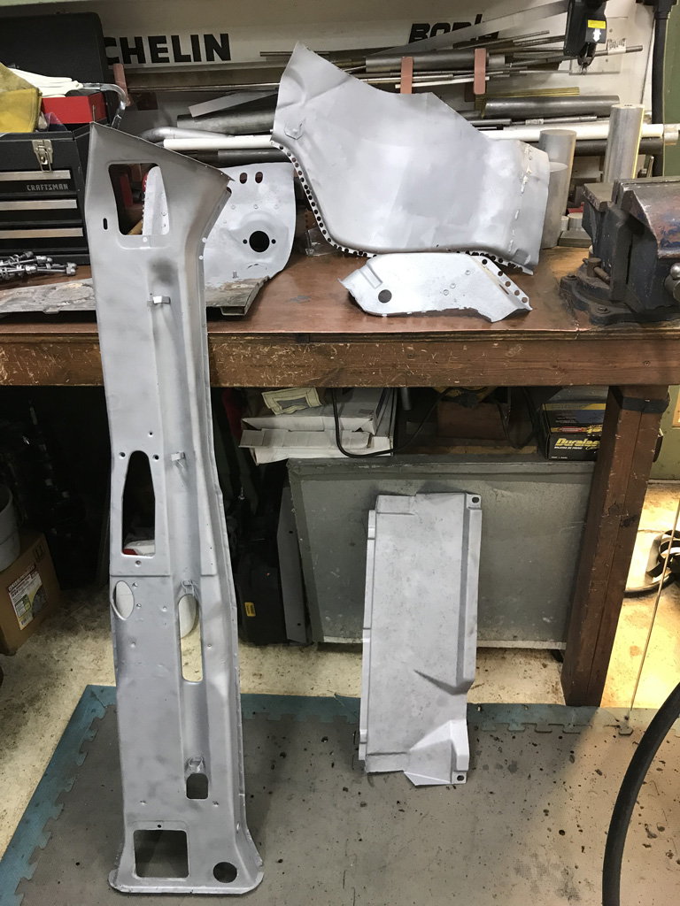
Luckily I got it done just before the hot humid weather rolled in - unlike last year!
Prepped the donor tunnel with Eastwood frame paint on the inside and Epoxy 2K on the outside. 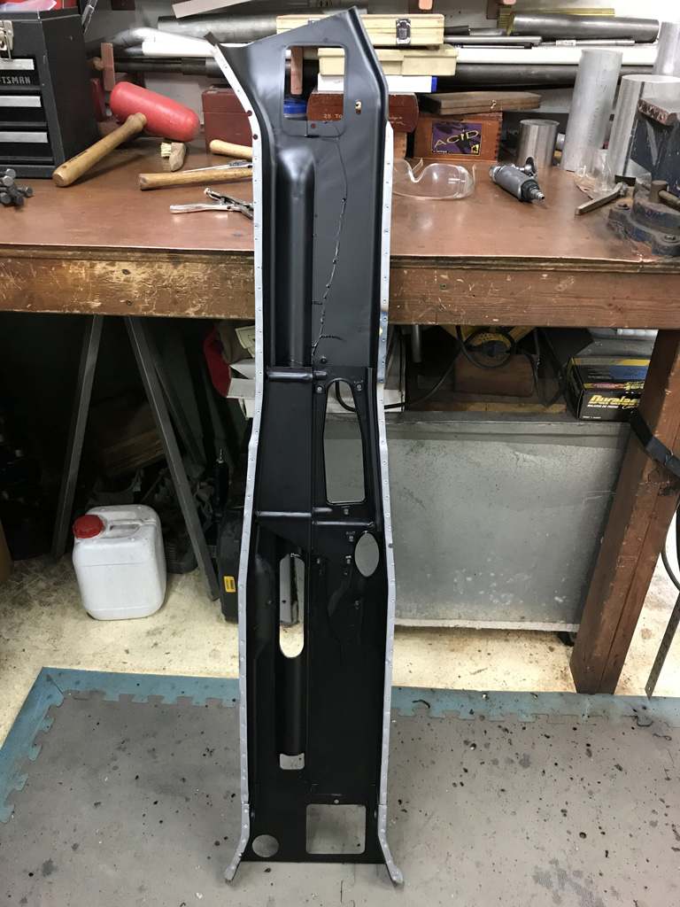
Metric tubing to rebuild the internals has arrived from Restoration Design but I've been putting that job off for a bit.
Posted by: Superhawk996 May 25 2020, 05:03 PM
Since parts came back from Ollie's I've been needing to check the line bore and make sure there aren't any issues that need to be addressed. 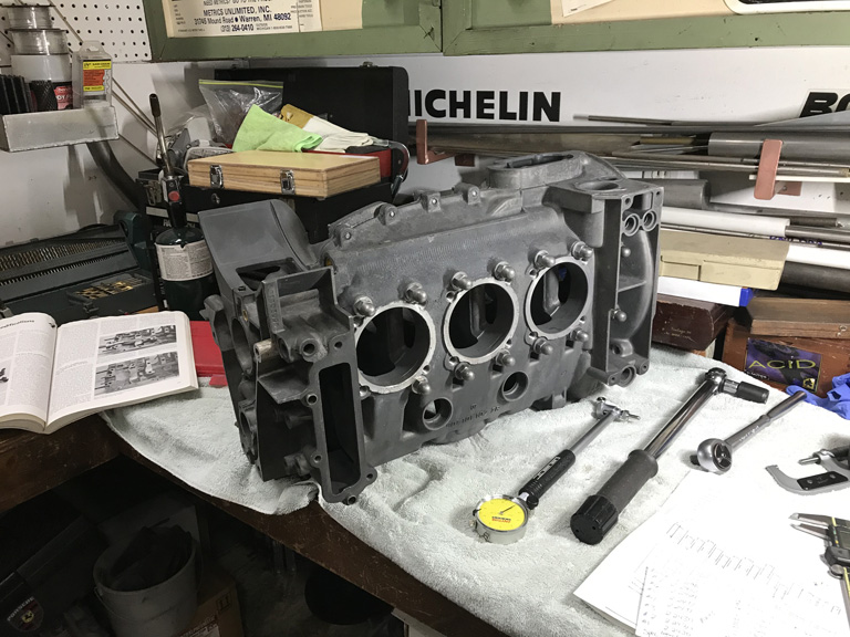
Unfortunately I ran into too much variability from my dial bore gauge. Despite setting it up with gauge blocks I'm having trouble getting the accuracy I need. More accurate bore gauge supposed to be here tomorrow.
Generally seems to be nice and circular but according to my dial gauge I'm running a little bit more toward the high side than I had hoped but need to keep in mind that we're working with a 47 year old mag case here. Bore's are nice and round though!
Posted by: Superhawk996 May 25 2020, 05:06 PM
Next order of business was to meausre the crank while I wait for the new bore gauge.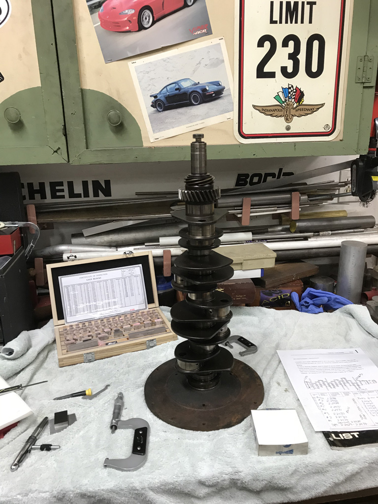
Measurements generally look good. 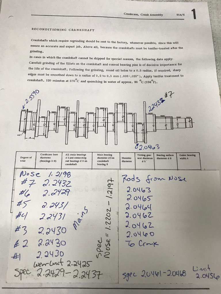
Generally same story here. Measuring above wear limit but a little bit on the lower end. I've got to balance that against the fact that I was using a relatively heavy touch on the Micrometer to get the smaller numbers rather than being light and getting a more appealing number.
Posted by: Superhawk996 May 25 2020, 05:12 PM
While waiting on the bore gauge, I decided to mount up a set of Glyco bearings and try some plastigauge.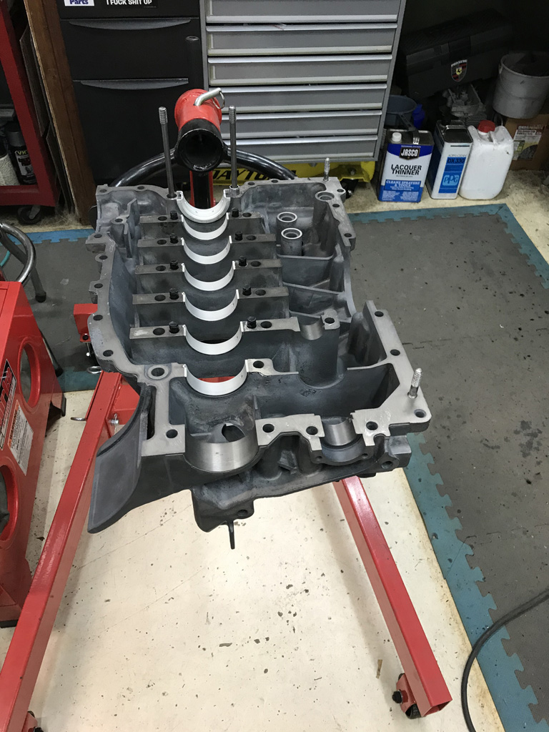
Coming up with 0.003" clearance which is a bit too loose for my liking. Would rather see 0.002" - 0.0025".
One option is to try ordering Porsche bearings but I hate to do that since my understanding is that Glyco was OEM supplier but there seem to be a lot of posts over on the bird forum that bearings from Porsche tend to run tigher. Wouldn't be unheard of for supplier to provide better spec parts to the OEM though.
Second option is to send the bearings out for specialized coating but that won't be cheap.
Third option is to cut the crank undersize but would rather not do that unless absolutely necessary.
Forth option - new crank assuming one can be located in better shape than what I already have.
We'll see what they measure with the more accurate bore gague but I really don't expect much change beyond a couple of tenths (0.0001"). Getting 0.0005" out via bearing tolerances is feasible but I don't think I'll get 0.001" out that way.
Since Porsche bearings are sold individually, I'll likely order 2 half shells and see if there is any promise there without having to go whole hog on a hunch.
Posted by: Superhawk996 May 27 2020, 05:35 PM
Not feeling any love from the new bore gauge. Accurate - yes. Repeatible - yes. Producing the desired anwer I'd like -- NO!
Well, I've now had the opportunity to measure the line bore and the bearing clearances.
The line bore is basically at the top end of the tolerance for the line bore size. I was hoping that it would have been bored at the bottom end. There is only a total tolerance of 0.0017" to work with. I didn't get an inspection sheet from Ollie's so I'll see what they think they bored it to but the bottom line is that I'm generally measuring 0.0005" or so over the upper limit of the line bore spec but I wouldn't put my hand tool accuracy up against a CMM measurement. We'll have to see what Ollies uses and where they think they lined bored it at.
My crank on the other hand is clearly toward the bottom end of the tolerance. Actually I'm only 0.0005" - 0.0007" off the Wear Limit.
My hope was for a tight line bore and being able to find a workable set of bearings based on some selective fitting. That doesn't appear to be in the cards.
Looks like there will be a 0.010" crank grind and the more expensive undersize bearings in my future. Win some, loose some. Bottome line: I'm coming up at 0.004" of measured main bearing clearance using micrometers and a digital bore gauge that are being set, checked, and repeatable with gauge blocks. Too much clearnace to assemble it as-is.
Any rework of the crank goes on the back burner for now. Potential COVID induced layoffs are a real possibility for me so expensive work will be put off until I know more. 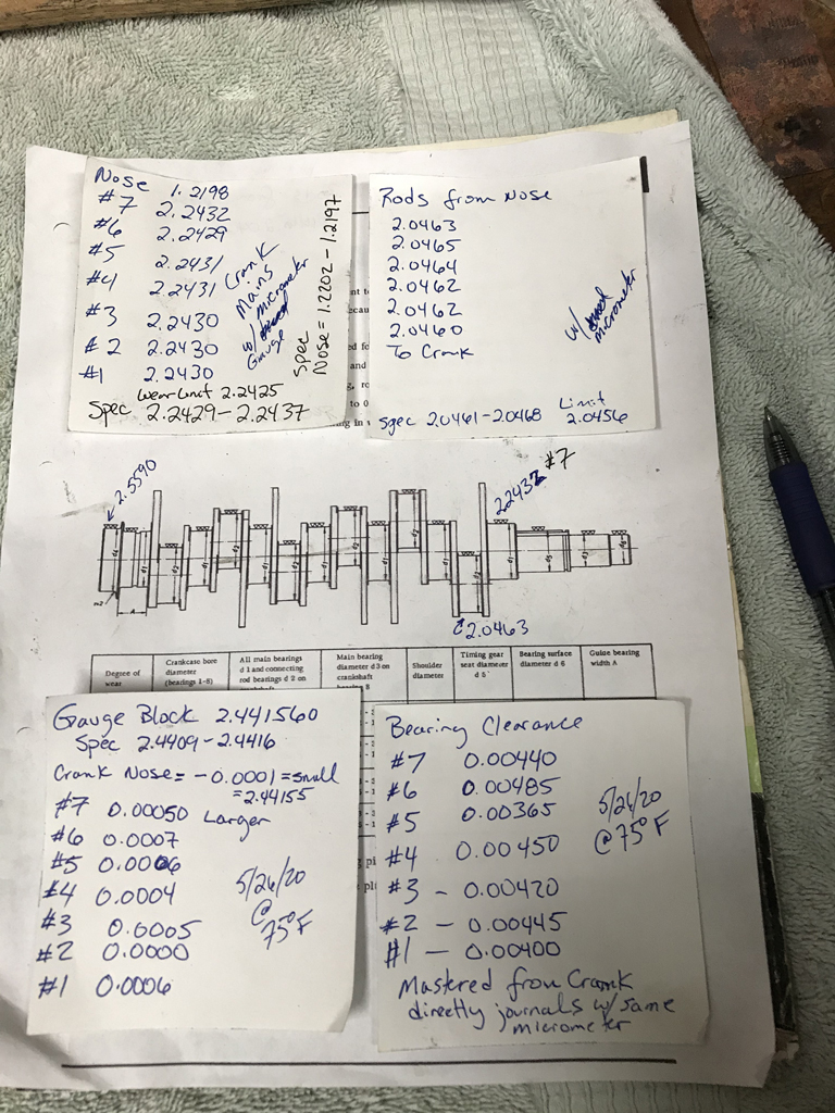
Posted by: Superhawk996 Jul 5 2020, 09:44 AM
Well after an extended period of time away from the garage, it's back to the grind . . . literally.
Spent a lot of time on my back yesterday grinding spot welds to remove the floorpan from the driver side longitudinal.
It's nice to finally have wide open space. I had been putting off this job for quite a while. Dreaded job, dirty, noisy, and tough working upside down. 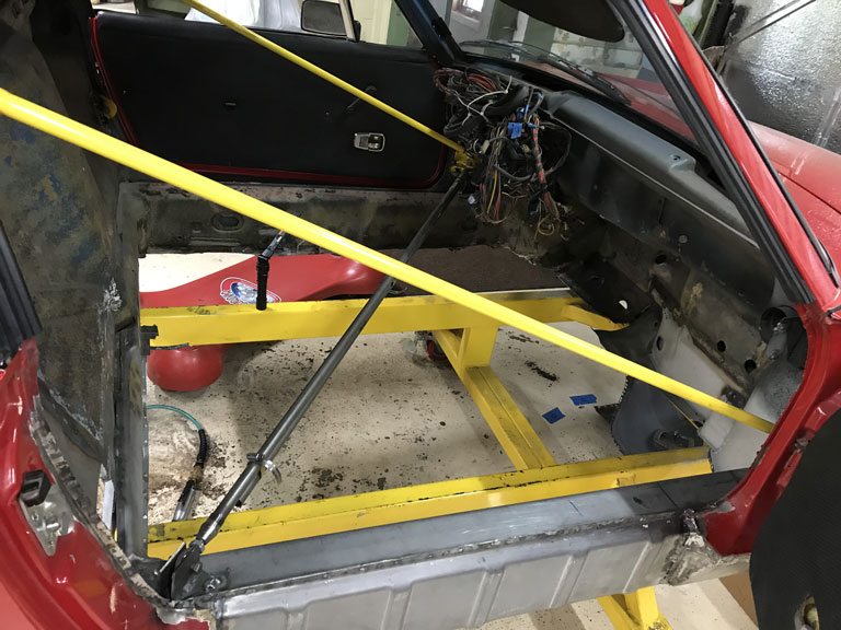
During the removal I discovered that the cross brace in front of the seats was completely eaten away about 3/8" from the driver side long. Luckily the long is completely unaffected. However, it's amazing that someone just fiberglassed over the rust perforation in the cross member as if it had no structural purpose. Simply amazing to me the that people did to these cars 
I have some localized pinholes in the driver side outer bulkhead near the shift rod. I decided that since the inner bulkhead is trashed at the floor pan, I'd remove the inner in order to gain better access to the outer.
Damn rodents had been storing nuts in the area between the panels. 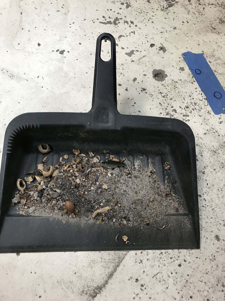
Damn previous owner somewhere along the line though they were making molds. Entire floor pan covered in fiberglass resin made this a dreadful job. My arms are still itching today. The good new is that except for a little resin clean up from the longitudinals and off the wheelhouse, all remnants of fiberglass are gone from the floorpan. 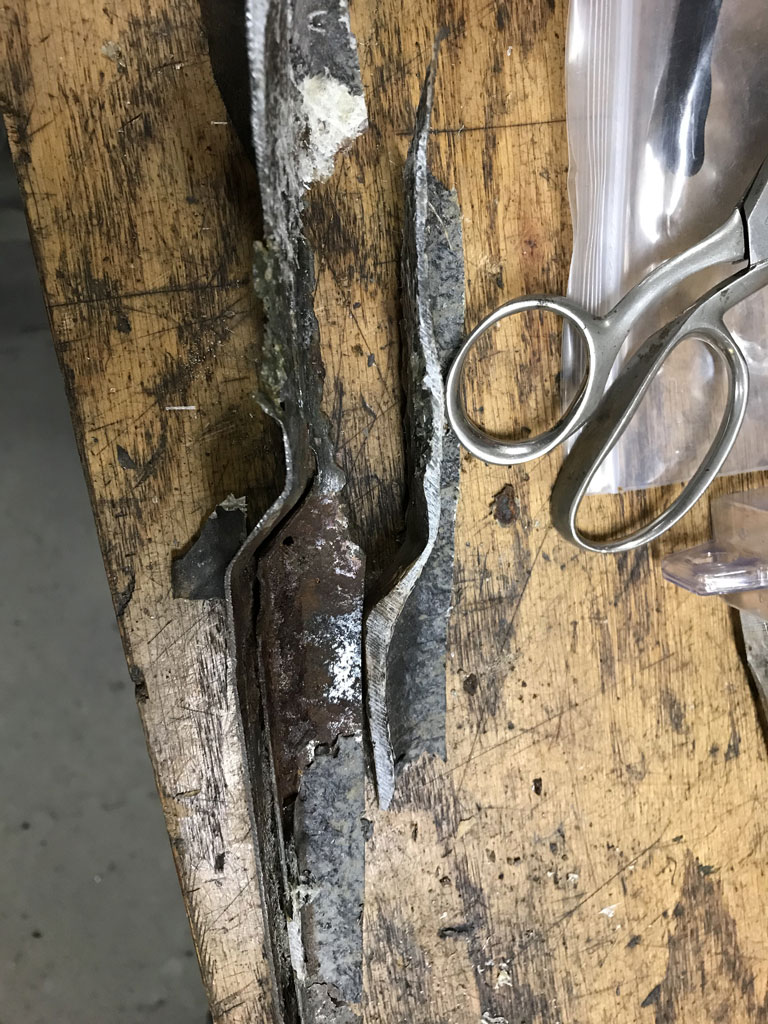
So with the driver side inner bulkhead removed, I can now get clear access to the outer in order to cut out the localized pin holes and replace with new metal from Restoration Design. 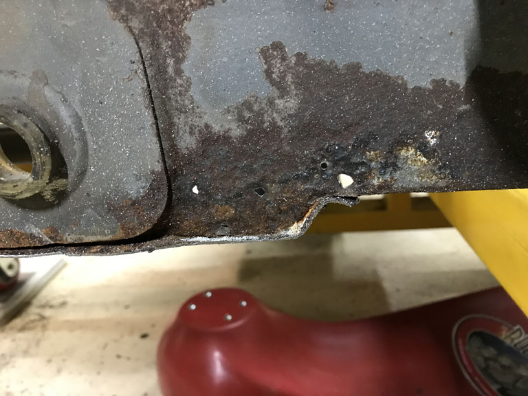
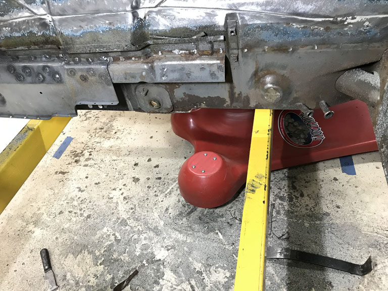
Posted by: Superhawk996 Jul 22 2020, 04:41 PM
Since Porsche bearings are sold individually, I'll likely order 2 half shells and see if there is any promise there without having to go whole hog on a hunch.
OK so #1 main bearing half shells came in and I thought I'd post the results.
This single OEM Porsche main bearing #1 is $75 per ½ shell. $150 for the bearing pair. Not a set – just Porsche OEM bearing #1.
I paid $165 for a whole SET of #1 - #7 bearings from Glyco – the OEM manufacturer. I’ve been reading stories on interwebz and the bird forum that Porsche 911 bearings are better and have tighter tolerances. In the nature of a skeptic I wasn’t sure I could believe Web info so I ordered just this one bearing for comparison
Yup – it’s true.
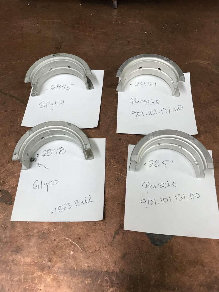
Glyco aftermarket bearing set
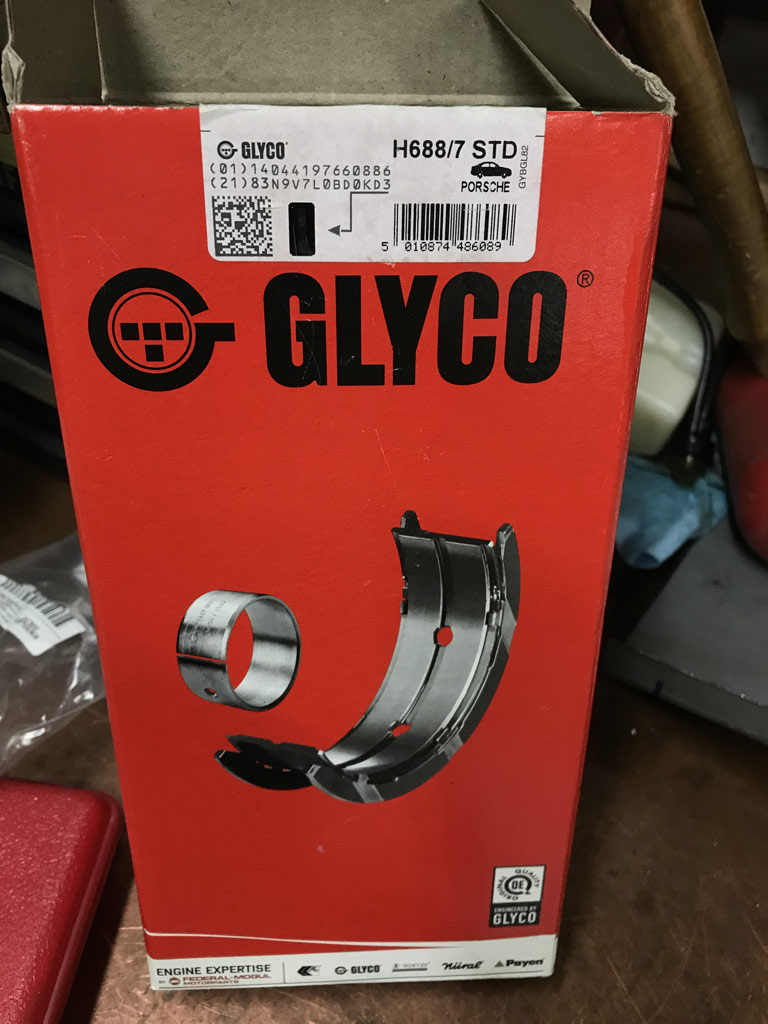
Porsche bearing ordered from Pelican - delivered in Porsche bag, Porsche p/n on bag and on bearing.
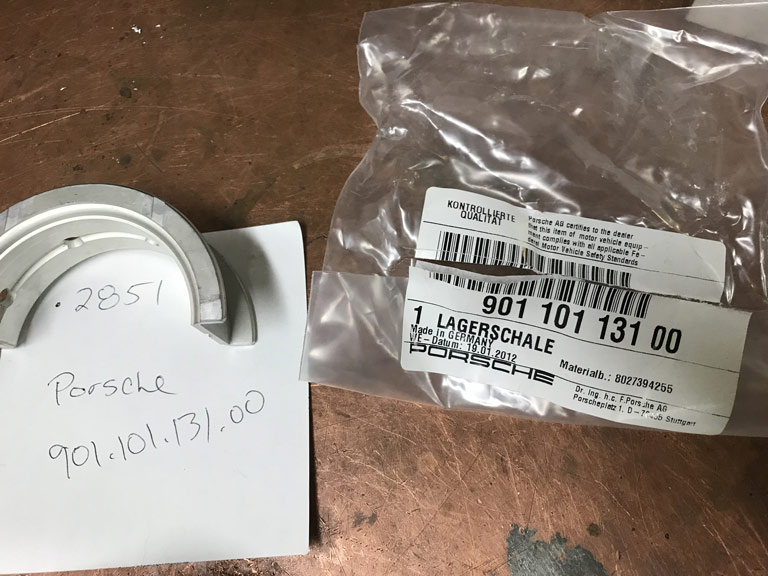
Although the OEM Porsche bearing bears the Glyco makers mark, it has a Porsche part number and different markings. Even the maker mark is slightly different. I'm not suspecting counterfit parts but see it as evidence that these Glyco aftermarket bearings are indeed different.
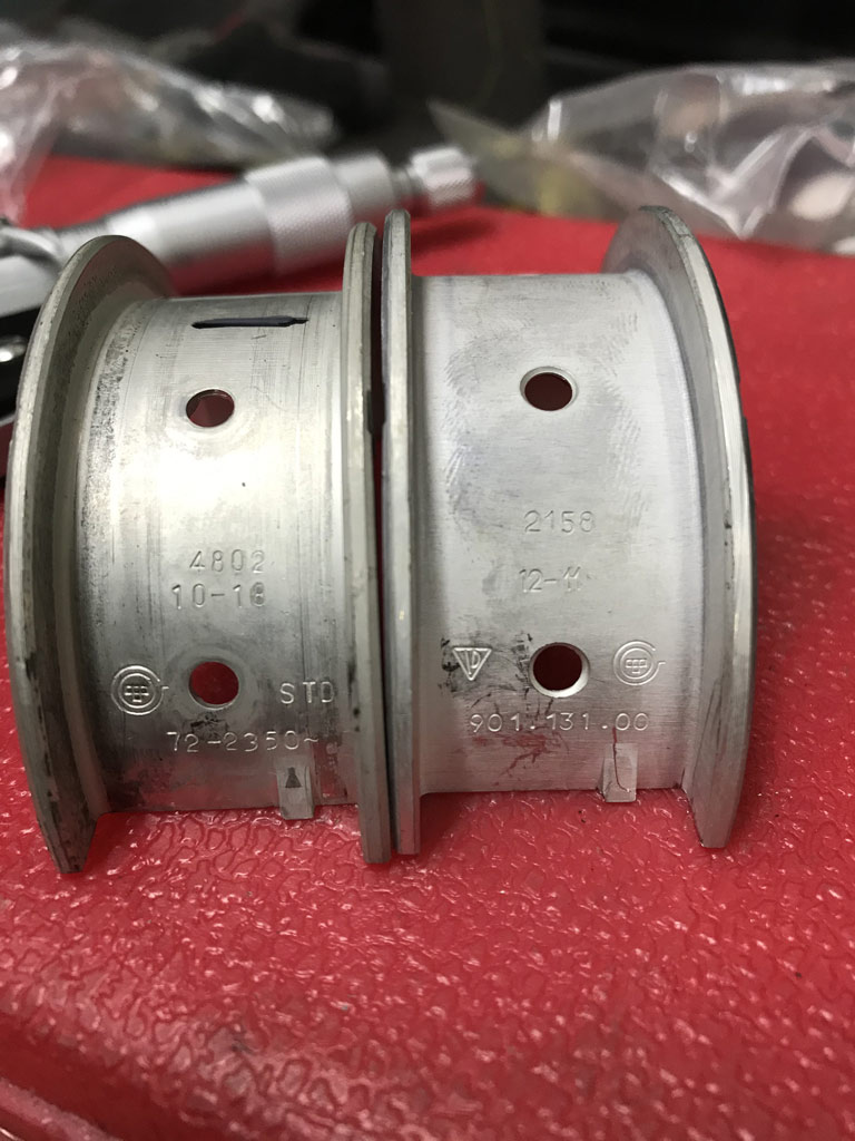
Clearly made in a different plant and/or via different sorting / handling / marking process.
More importantly these bearings would give me a tighter fit by around 0.0009” or nearly 0.001”. That is huge. I’d like to target 0.0025”-.003” max but was measuring 0.004”+ on the Glyco bearings with both plastigauge (well really .003” gauge that didn’t appear to crush fully) and the math between bore gauge of the bearing and the crank as mastered off the micrometer used on the crank.
Yes - I only measured 1 point on this comparison but it aligns with the postings on the bird forums about differences as posted by those that invested more time measuring two or three points per bearing.
Very frustrating.
Looks like I may end up having to pony up $850 dollars for the OEM Porsche Bearings. The other option is upgrade pump to 76' 4 rib pump or maybe a 930 pump but that is just counting on pump volume to mask larger clearances that would be present by using the aftermarket bearings.
Other option is grind crank undersize and be sure they grind to the high spec and then polish down as needed. Not ideal either. Time to think about this a bit more.
Posted by: Dion Jul 23 2020, 09:10 AM
Glad to see progress on the chassis.
Sorry about the bearing situation. You’ve done a tremendous amount of research into that. Amazing the price tag on the Porsche OEM bearings. Tough call. I’d have to go with the Porsche ones. Sounds like less of a headache in the long run. Have you looked to see if any deals to be had with EBS Racing? Only a suggestion. When i was working on my 2056 their prices at the time were cheaper than the bird or the dealer. Not sure of today but worth a look maybe. Save some coin. Good luck.
Posted by: barefoot Jul 24 2020, 06:16 AM
Prepped the donor tunnel with Eastwood frame paint on the inside and Epoxy 2K on the outside.
Metric tubing to rebuild the internals has arrived from Restoration Design but I've been putting that job off for a bit.
[/quote]
A general question on clutch tube failures. If the tab washer is correctly fitted at the tranny bracket that holds the rotating wheel, all the thrust force on the clutch cable should be absorbed by this attachment and not on the clutch tube ???
There are so many failures of the clutch tube that my guess may not be quite accurate, any insight from experienced builders ?
Posted by: Superhawk996 Jul 24 2020, 06:51 AM
A general question on clutch tube failures. If the tab washer is correctly fitted at the tranny bracket that holds the rotating wheel, all the thrust force on the clutch cable should be absorbed by this attachment and not on the clutch tube ???
There are so many failures of the clutch tube that my guess may not be quite accurate, any insight from experienced builders ?
@http://www.914world.com/bbs2/index.php?showuser=15673
The clutch tube has a bent radius as it travels through the tunnel.
Your point would be correct IF the cable traveled in a straight line. Given that the clutch cable tunnel tube does have a radius to it, there are side forces imposed on the cluth tube.
As you apply tension to the clutch cable, it wants to revert to a straight path, but, of course it can't being constrained by the tube. As it attempts to go straight, it imposes side load on the tunnel tube.
In normal use the side load on the tunnel tube is managable. The problem of side force get exaggerated by dragging / unlubed cables, the clutch cable wheel getting bound up and not rotating freely, high force pressure plates, and just plain old fatigue of the brazing over 50 years of use. Remember typical life cycle for a car from this era wasn't even 10 years, 100,000 miles.
Picture below should help visualize the radius of the clutch cable guide tube. In the picture you can see two things.
1) The clutch tube has been repaired with the "hook" fix at the front end of the tube.
2) The stamped braket that supports the tube behind the shifter his broken / torn.
Hard to say which occurred 1st but it give you a sense that things do fatigue and break either the support braket and/or the tube attachements.
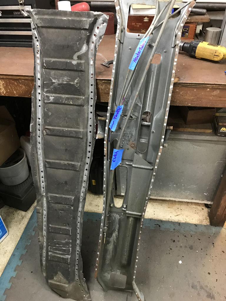
Posted by: barefoot Jul 24 2020, 05:20 PM
A general question on clutch tube failures. If the tab washer is correctly fitted at the tranny bracket that holds the rotating wheel, all the thrust force on the clutch cable should be absorbed by this attachment and not on the clutch tube ???
There are so many failures of the clutch tube that my guess may not be quite accurate, any insight from experienced builders ?
@http://www.914world.com/bbs2/index.php?showuser=15673
The clutch tube has a bent radius as it travels through the tunnel.
Your point would be correct IF the cable traveled in a straight line. Given that the clutch cable tunnel tube does have a radius to it, there are side forces imposed on the cluth tube.
As you apply tension to the clutch cable, it wants to revert to a straight path, but, of course it can't being constrained by the tube. As it attempts to go straight, it imposes side load on the tunnel tube.
In normal use the side load on the tunnel tube is managable. The problem of side force get exaggerated by dragging / unlubed cables, the clutch cable wheel getting bound up and not rotating freely, high force pressure plates, and just plain old fatigue of the brazing over 50 years of use. Remember typical life cycle for a car from this era wasn't even 10 years, 100,000 miles.
Picture below should help visualize the radius of the clutch cable guide tube. In the picture you can see two things.
1) The clutch tube has been repaired with the "hook" fix at the front end of the tube.
2) The stamped braket that supports the tube behind the shifter his broken / torn.
Hard to say which occurred 1st but it give you a sense that things do fatigue and break either the support braket and/or the tube attachements.
In my case the clutch tube had seperated form the front of the tunnel and gotten itself onto the WRONG side of the shifter mechanism, Wore a groove into the tube as I got the car. I was able to fashion a clamp from a conduit bracket & bolt it ti the tunnel side. Worked OK after that.
Barefoot
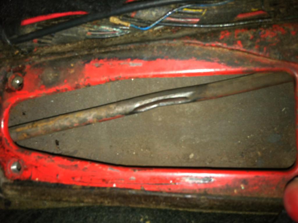
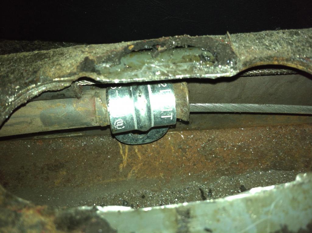
Posted by: Superhawk996 Jul 26 2020, 08:16 AM
@http://www.914world.com/bbs2/index.php?showuser=15673 .
That is amazing that it was clunking around in the tunnel and hitting the shifter that long to wear a hole in the clutch tube like that.
Good job getting it clamped back down!
Posted by: Superhawk996 Jul 26 2020, 08:23 AM
Been a little distracted by side jobs.
Did a repair for my neighbor's tractor for some sort of cover to the hydraulics. Since I occasionally get use of the tractor for winter it was only a fair trade. 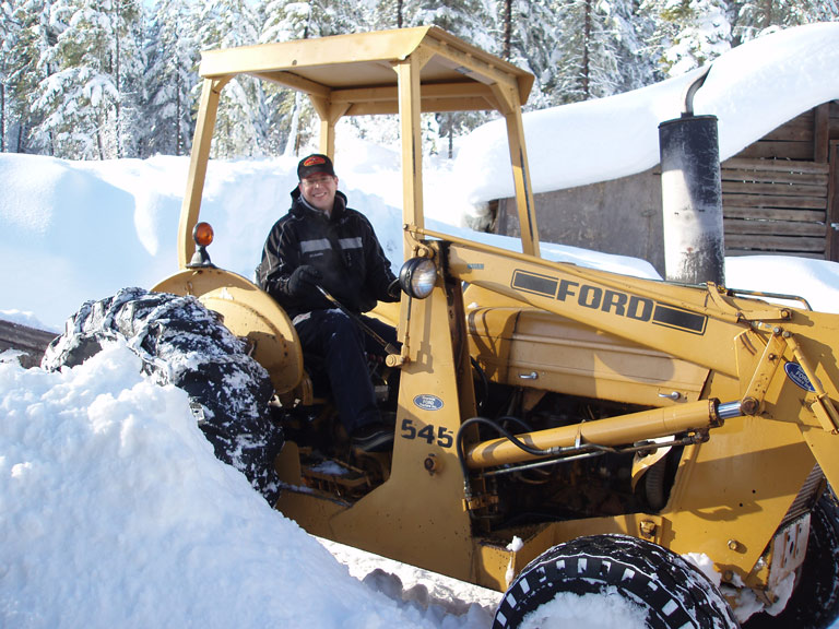
OEM part is diecast zinc pot metal. It had broken the ears off the cylindrical portion.
Pot metal is a PITA. Can't really weld it per se. However, I do have some Aladdin 3 in 1 rod that comes in handy for pot metal repairs. It is sort of a cross between soldering with an OxyAcetylene torch and brazing.
The problem is that the difference between being hot enough to flow the rod and the material just turning into mush is only a few degrees apart.
I was able to get it "glued" back together with the Aladdin rod and then remachined it but don't have much confidenece in the long term durability since I don't know what sort of loads are on it.
I decided to make a replacment out of 7075 Aluminum. That one should last. 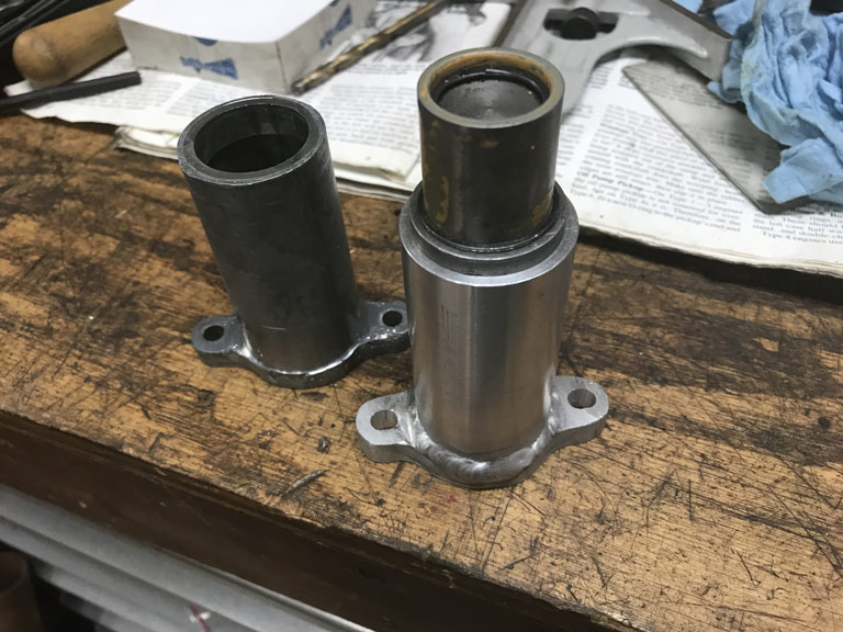
Posted by: Superhawk996 Jul 26 2020, 08:30 AM
The other distraction was trying to fix an AAR valve that had the heater wire intermittently shorting out to the housing. Not Good
I tried to set it up in a 4 jaw chuck to peel off some of the metal housing tube that supports the wire where it exits the housing. 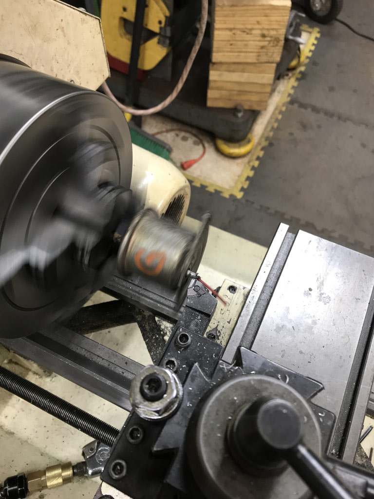
Bottom line: Complete failure and waste of several hours of work but at least it fun trying to save it.
In the end just as the bit was cutting though the last of the metal tube, it grabbed a few strands of the copper and shredded the little bit of the wire insulation that I had just gotten cleaned off.
Having failed, I completely disassembled the AAR down to the internals. Looks like this could be ripe for some sort of conversion to have a stepper motor drive the physical AAR valve. Obviously that would require an Arduino or something in there to drive the stepper motor but it could have opportunity to "tune" the AAR as the vehicle warms up.
Anyway -- failure for now and something to think about for the future.
Posted by: Superhawk996 Jul 26 2020, 08:39 AM
So back to some real work.
I had to pull the shifter bushing support off the old sheetmeal and get the pass-thru hole positioned properly. 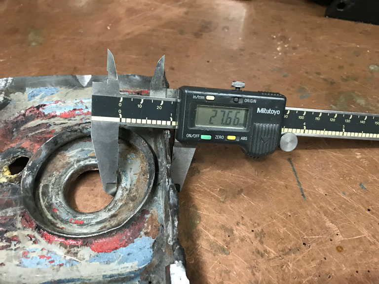
Welded it to the new sheetmetal and got it painted with some Eastwood frame coating to prevent surface rusting until I can get 2K epoxy on the exterior. 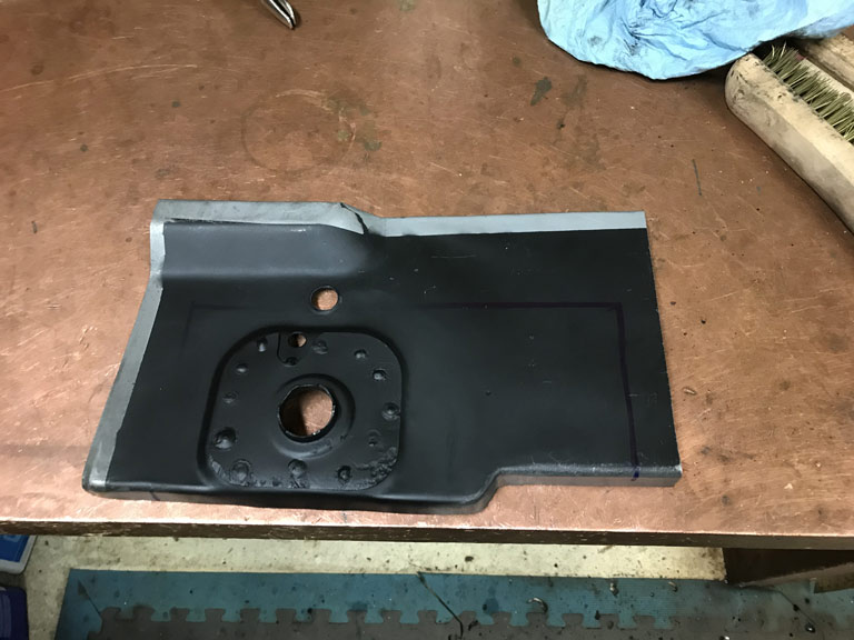
An then spent a couple more quality hours in the engine compartment fitting it up and trimming for welding today. 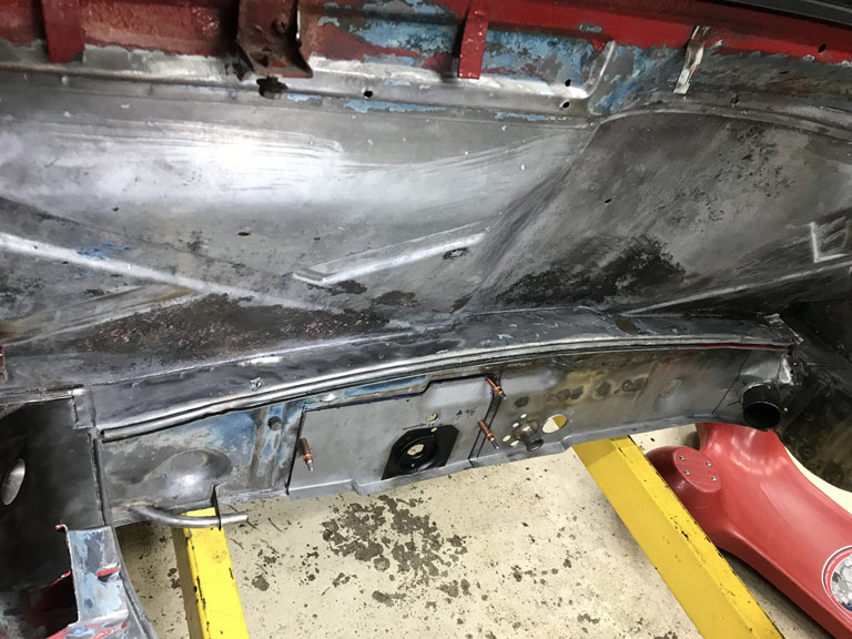
I don't know what it is about working in the "hell hole" but it seems like everytime I get scooted under the car I realize I've forgotten some tool, my sribe, sharpie or whatever.
Posted by: Superhawk996 Jul 26 2020, 05:17 PM
Outer bulkhead panel is done. I have the leftover piece of the panel outboard of the shifter left and won't be using it. If anyone is needs it, it's yours for the cost of shipping.
Seems to take forever to get even these little panels installed. 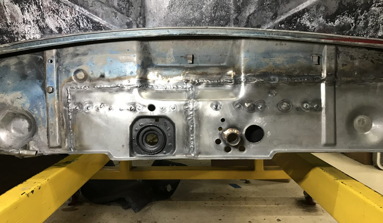
Really pleased with the weld penetration. 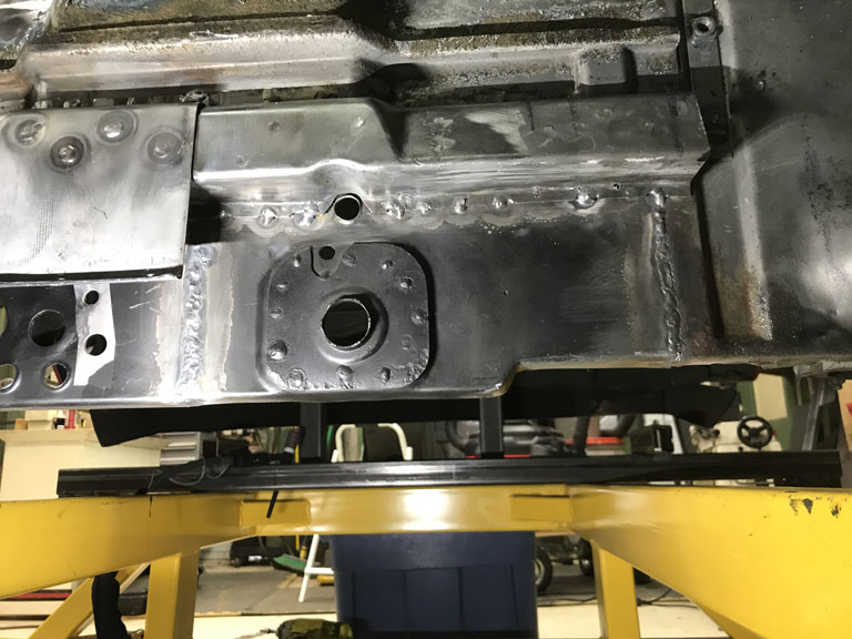
Nice and strong and will clean up with minimal weld clean up from the front side when it's time to do the finish work. 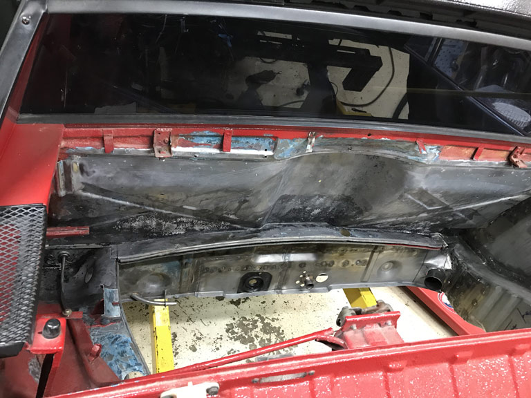
Looks like I can spend some time after work this week getting the inner panel ready for install.
Posted by: BeatNavy Jul 26 2020, 05:48 PM
That looks really clean and well done. Nice job. That lower firewall is NOT easy!
Posted by: Superhawk996 Aug 2 2020, 10:45 AM
Thought I'd be welding in the last portion of the driver side inner bukhead panel but it turns out that I've got two headaches.
One is real and I don't feel like welding right now. Probably dehydrated and need to drink more water and a couple Ibuprofen will help. Hopefully I'll be fixed shortly and welding in an hour or so.
The other headache was the repair panel I purchased from RD is missing a form feature to clear the floorpan stiffening dart. I'm mildly disappointed in RD. I really like these guys! But, the 325L panel that I purchased from them needed way more fabrication work than the similar part on the passenger side that I purased from AA for only about $10 more.
As I was finishing up panel prep yesterday, I noticed the lack of the floorpan form feature. Initially I was thinking maybe that floor pan stiffening dart isn't on the driver side.
Quick mockup of the floorpan has a dart there. 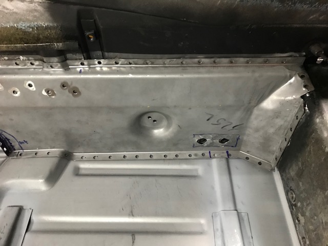
More work to prep the panel needed before I can weld it in.
In addition to this form feature, I also had to completely do the weld flange inside the tunnel. Yeah, Yeah . . . I know all panels are going to need some tweaking. But the AA panel on the passenger side had the tunnel flange formed by the stamping dies and fit the tunnel near perfectly as received. All in all, this was a couple additional hours of panel prep that I didn't have to do on the AA panel used for the passenger side. 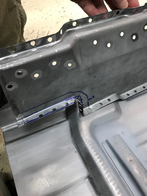
Don't get me wrong. I'd still go to RD for panels but was just surprised and/or disappointed that I had to do this work on the RD driver side part and not on the AA passenger side part. Likewise, I can't say with certaintly that the AA driver side part is any better. Just posting as information but not trying to run down RD.
Anyway, it as a good chance to get the floor pan halves and the donor tunnel in for a quick mockup. Nowhere near ready to weld in floorpan yet but sometimes just seeing a mockup give me a sense of hope & progress. 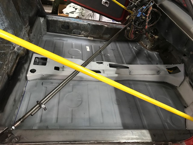
11/10/2020 update: have heard from @http://www.914world.com/bbs2/index.php?showuser=8858 at RD that the 325L panel stamping has been revised to add the floor pan formation to more easily fit up. Great company, great customer service on all that I’ve ordered and most importantly incorporating continuous improvement to make their products even better!
Posted by: Superhawk996 Aug 3 2020, 02:39 AM
Got up at 4:30am meeting with Asia only to find out they cancelled the meeting about an hour ago after I had already gone to bed
Driver side lower bulkhead sucessfully installed last night. 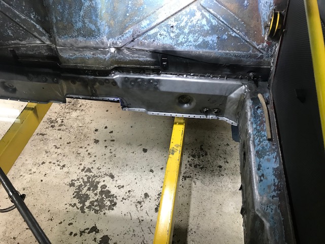
Time to move on to another section of bad sheetmetal and the last before I can install floorpan.
Next up: The driver pedal box area and driver side wheelhouse.
Posted by: Superhawk996 Aug 3 2020, 08:03 AM
This jalopy supposedly was a Florida car. I did find some sand in the passenger side longitudinal when I cut that apart which was completely replaced. Video below is of the driver side.
https://www.youtube.com/watch?v=PXeAENauvsY
Looks like I'll be at least doing a small trap door in the driver side longitudinal to get the rest of the sand out. There were small rust holes in the rear portion of the front wheel wheel to longitudinal area - I'm pretty sure this is how the sand got in there.
Will also need to run a borescope into driver side long just to make sure. Everything is solid with a pick and no signs of pinholes but better safe than sorry.
Posted by: tygaboy Aug 3 2020, 08:07 AM
It's fascinating to me how we each approach the repair process. I've done two cars worth of that lower firewall/rear floor repair and it wouldn't have occurred to me to install the firewall before the floor.
Not challenging your approach at all, just fun to see the other ways folks do things.
Regardless, you're moving right along and it's looking great!
Posted by: Superhawk996 Aug 3 2020, 08:14 AM
It's fascinating to me how we each approach the repair process. I've done two cars worth of that lower firewall/rear floor repair and it wouldn't have occurred to me to install the firewall before the floor.
Not challenging your approach at all, just fun to see the other ways folks do things.
Regardless, you're moving right along and it's looking great!
@http://www.914world.com/bbs2/index.php?showuser=19241
Considering my aproach was to build the passenger side innner wheel well and long from the inside out to avoid cutting the rear fender it's no wonder I'm doing it backwards.
Plus, I need the floorpan out to better access the driver footbox and wheelhouse area. Had I been able to save the tunnel and/or more of the lower 1" perimeter, I would have done it differently. My thought was that the floorpan doesn't offer any vertical stiffness or vertical structure which would move around my suspension points in Z height.
The floor pan does prevent matchboxing fore/aft movement though and I've tried to brace this movement with the diagonal brace.
The potential for movement keeps me measuring my suspension pickup points like an OCD maniac though.
Posted by: Superhawk996 Aug 9 2020, 08:33 AM
Well in an effort to get all the sand out of the driver longitudinal, I had to cut some holes.
The front driver side longitudinal had some minor rust at the transition to the floorpan. This was an obvious place to put an access hole. It won't be seen once reapaird and the floopan is reinstalled. 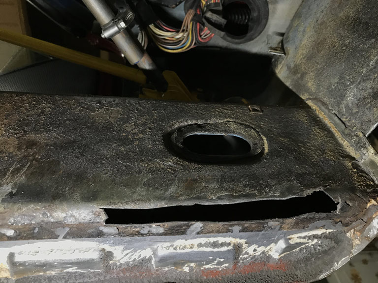
The rear was obvious too. There was a poor repair of the driver side jack point and I wanted to see what was under there. Usually it is rusted out in this area from the pyramid holding water and debris leading to localized rot. Sure enough. 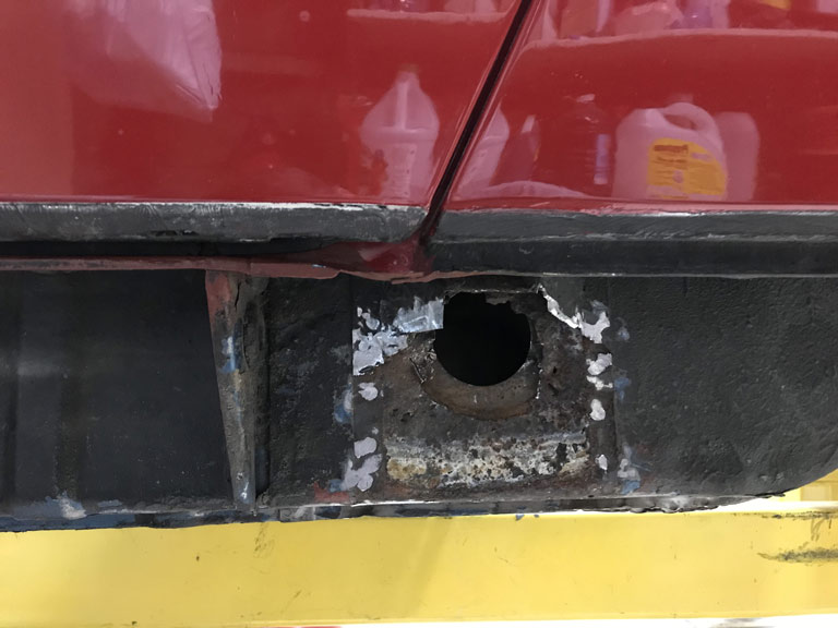
Having removed the sand over the course of several hours of swearing and cutting up my hands manipulating a small section of 3/8" vinyl hose (attached to shop vac) back and forth in the long though these access holes, I moved on.
Demolition of the pedal box area was entertaining. The floor pan that normally covers the rear mounting point for the front cross member was basically gone. Simply covered with a skim of fiberglass, rotted sheetmetal, and of course undercoating to hide the whole show. 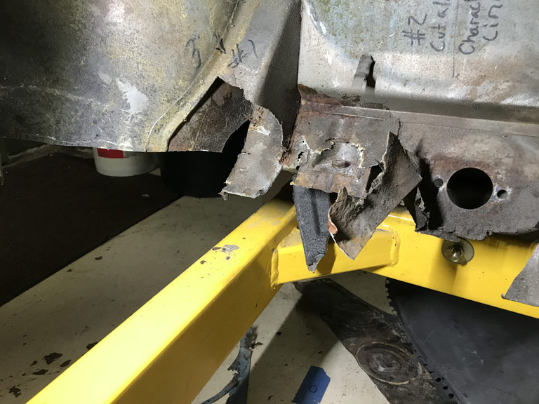
Well at least I'm moving forward and no longer working in the engine compartment for a while. We'll see about that because I might be cutting a surgical flap via the driver side wheel house inner in order to properly repair that driver side jack point. We'll see.
Posted by: Superhawk996 Aug 9 2020, 08:50 AM
The aftermarket bearing vs. Porsche OEM bearing saga continues.
I ordered two half shells at about $45 each that serve as main bearings for bearings #2 through #7.
I was hoping that they would measure a little tighter than aftermarket Glyco as bearing #1 half shells did. 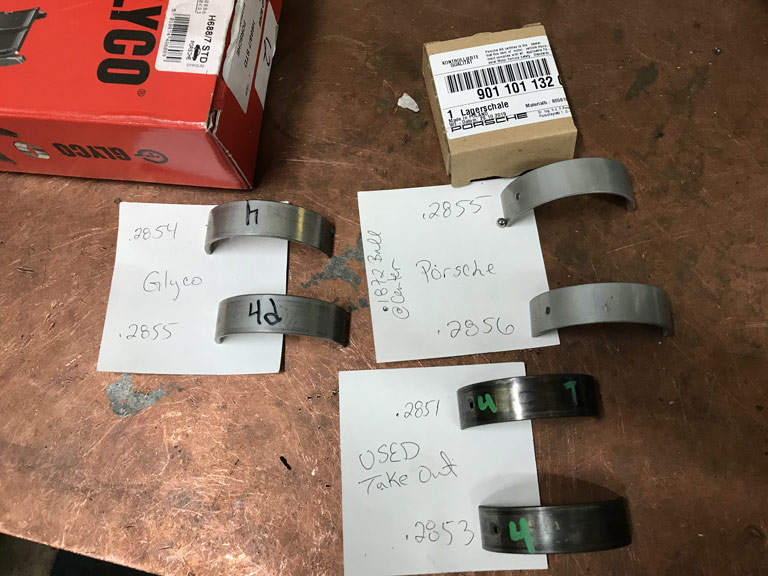
Nope. Well, maybe by 0.0001" - 0.0002" but I was hoping for something significant.
Posted by: 914forme Aug 9 2020, 10:22 AM
What is the goal?
From what I see you have had .0004 and .0003 wear on the bearing surfaces. What are your crank journals.
General rule of thumb is your looking for crank bearing clearance of 0.0020 - 0.0025.
I know you most likely know this, and or have access to the people who do know being part of th automotive industry. But with out the magical numbers and what these are once in the saddle and cap. We are just guessing with the clues given. Unless it was detailed a while ago and I did not read it.
Posted by: bkrantz Aug 9 2020, 08:43 PM
Demolition of the pedal box area was entertaining. The floor pan that normally covers the rear mounting point for the front cross member was basically gone. Simply covered with a skim of fiberglass, rotted sheetmetal, and of course undercoating to hide the whole
show. Well at least I'm moving forward and no longer working in the engine compartment for a while. We'll see about that because I might be cutting a surgical flap via the driver side wheel house inner in order to properly repair that driver side jack point. We'll see.
With all the crimes committed with undercoating, maybe it should be locked up and sold only to those with good intentions (and skills).
Posted by: Superhawk996 Aug 10 2020, 03:52 AM
What is the goal?
From what I see you have had .0004 and .0003 wear on the bearing surfaces. What are your crank journals.
General rule of thumb is your looking for crank bearing clearance of 0.0020 - 0.0025.
I know you most likely know this, and or have access to the people who do know being part of th automotive industry. But with out the magical numbers and what these are once in the saddle and cap. We are just guessing with the clues given. Unless it was detailed a while ago and I did not read it.
@http://www.914world.com/bbs2/index.php?showuser=2388
Agree with Goal of 0.0025 - 0.0003". The issue I had was that Line bore is at the high end of spec and the crank is about 0.0005" above wear limit and main bearing clearance was coming in at about 0.004" +/- a few tenhs, measued with bore gage and seemed to have a lack of complete crush on 0.003" Platigauge.
I'll probably do another trial assembly with crank nose bearing in place to double check all this. But it's looking more like crank is going to have to go undersize to get to 0.0025". Of course that also means undersize main bearings. This is why I was trying to figure out if there was something to be gained with the super expensive OEM bearings from Porsche.
Will likely do a triple check with the next size up of Plastigauge too that cover 0.004" and larger.
Posted by: 914forme Aug 10 2020, 05:05 AM
Got it, best of luck
Posted by: Superhawk996 Aug 15 2020, 12:36 PM
Well the time has come to do the part I've been dreading for a while. Time to fix the pedal box area.
Part of the dread was over stripping of the seam sealer from the area under the gas tank. My Wurth flail wheel won't fit in there. Turns out it wasn't so hard to do with a drill and really stiff wire wheel. Access sucks but it was doable. 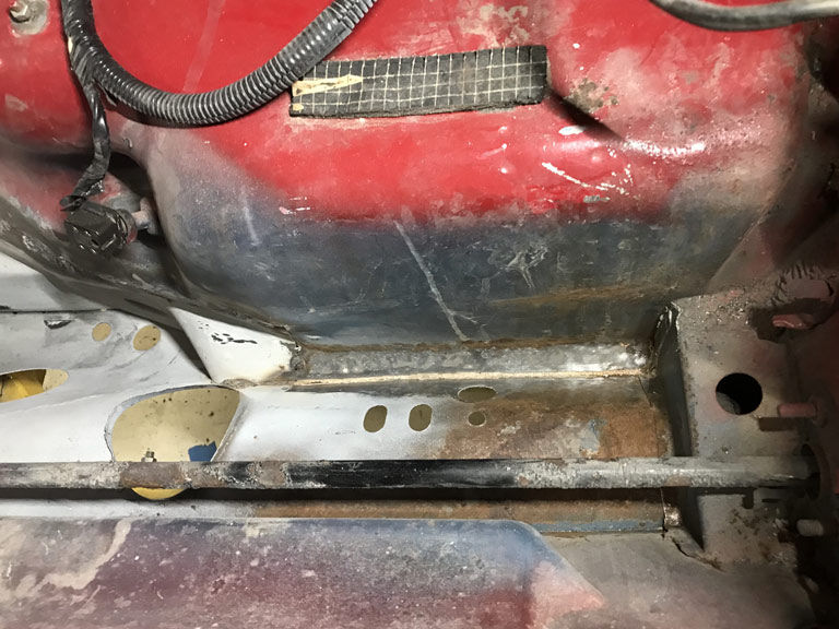
Next up was the need to create a tuna can flap to gain access to the area. The weld seam will go right below the area where the flap is normally spot welded down. This will give me a nice area to weld to with double metal thickness. 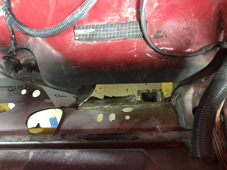
And as viewed inside the cabin.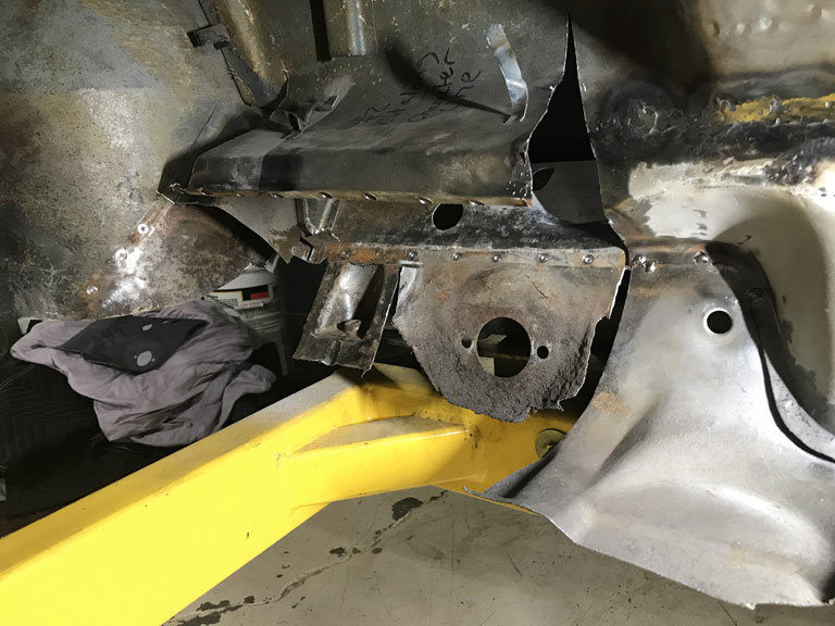
Currently prepping the new sheet metal with POR15 Metal Prep as I add this build entry.
I've tried both Ospho and POR15 Metal Prep and I'm leaning toward the Metal Prep as my preferred product. Just seems to work better for me and leaves a thin layer of zinc that holds off the surface rust until I can get primer on it.
Posted by: Superhawk996 Aug 16 2020, 04:08 PM
Well I knew this was going to be a PITA and it's turning out to be that way.
Initially I was hoping to use the donor sheet metal as-is without having to remove the suspension point that anchors the steering crossmember at the front firewall area.
There was simply too much car to car variation to make it work. I had initially marked the cross car postion of the pedal sled & master cylinder mount as reference.
There was no way to get that dimension to where it started and to simultaneously have the downward turned flange of the wheelhouse in the right place.
So off with the old pick up point. I have a new one from RD anyway just in case. I guess that was a good call. 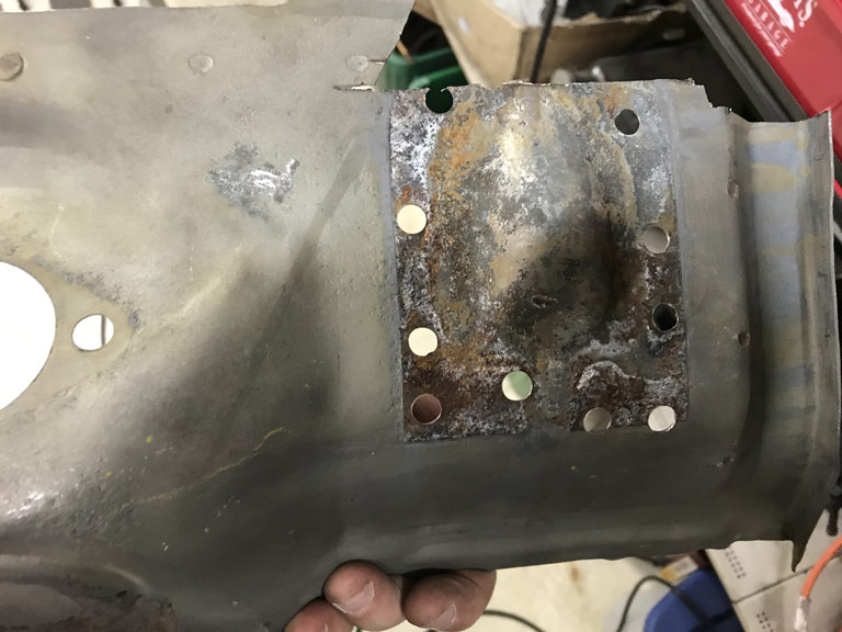
The positive side is that I can now sandblast the corrosion that was trapped internally.
Next problem was to make sure the floorpan character lines lined up between left side and the right side AND to have the pedal sled fit.
More mockup. 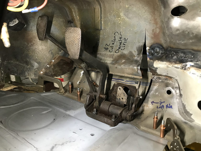
Well, when all is said and done, with everything where it belongs, I have about a 6-7mm gap between the panels.
Not insurmountable but it goes to show how much variability there can be beween donor sheetmetal and the vehicle it's going into. I would have expected a 3mm gap simply from the kerf when I split the panel over a year ago. The other 3mm is basically car to car variation.
It will all work out after I trim a thin gap filler and I'll be sure to use a copper backer to prevent welding problems. . . . I hope. 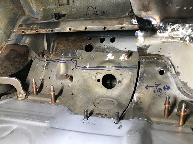
Posted by: Superhawk996 Aug 19 2020, 05:25 AM
Weeknight project was to get three tachometers bench tested to verify functionality.
Quick overview of setup details in the video. Currently working to setup as a little Arduino program that can do this without all the test equipment. This was done manually with a frequency generator controlling the frequency of the pulses to make sure the setup with a MOSFET driver was going to work to drive the coil.
https://www.youtube.com/watch?v=EO3XCJQ9tW4
Posted by: bbrock Aug 19 2020, 08:07 AM
That's awesome! If you get the Arduino setup working, I may have to copy it. Nice work on that pedal box too.
Posted by: Root_Werks Aug 19 2020, 08:53 AM
I haven't been keeping up on this thread enough, wow! It's come a long way, keep at it!
Posted by: bkrantz Aug 19 2020, 09:13 PM
Nice work on the pedal box area. That's one I did not have to repair on mine, and glad to skip it.
Posted by: Superhawk996 Aug 23 2020, 03:18 PM
That's awesome! If you get the Arduino setup working, I may have to copy it. Nice work on that pedal box too.
PM sent.
Arduino now functional to run the tach up and down by about 1000 RPM increments to avoid sudden changes that tend to bounce the needle off the pins.
If anyone wants a copy of the Arduino code, PM me, it's yours for the asking. Not elegant (I'm not a software guy) but functional.
https://www.youtube.com/watch?v=phWebSTri-w
Equipment needed:
12v power supply or battery
Sparkfun.com MOSFET shield
Arduino Uno
12v coil (can also use a inductor of about 2-9mH and a ballast resistor)
Associated jumper/test wires with alligator clips
Posted by: brcacti Aug 23 2020, 05:12 PM
"Where the heck did the year go?"
The older you are it seems the faster the years go by.
So drive that 914 when you can
Posted by: Superhawk996 Aug 23 2020, 07:12 PM
"Where the heck did the year go?"
The older you are it seems the faster the years go by.
So drive that 914 when you can
@http://www.914world.com/bbs2/index.php?showuser=23302
There, I updated the header for you. It has gotten out of date
Purchased in April of 2018 or something close to that. I did lose the better part of spring & summer 2019 to a skin graft surgery but that's just a lame excuse for not having gotten more done. I can't wait to drive it but I'm not even close yet. I hope to have all structural sheet metal and floorpans resolved by Jan/Feb.
Then the real fun begins. Need to put engine together, check out a transmission, and refresh a bunch of suspension stuff.
I'll be lucky to have it off the build cart by the 3 year anniversary. What was I thinking trying to save such a dog
Posted by: 914_7T3 Aug 23 2020, 07:27 PM
I'll be lucky to have it off the build cart by the 3 year anniversary. What was I thinking trying to save such a dog
It was the right thing to do!
Posted by: Superhawk996 Aug 24 2020, 05:54 AM
I'll be lucky to have it off the build cart by the 3 year anniversary. What was I thinking trying to save such a dog
It was the right thing to do!
@http://www.914world.com/bbs2/index.php?showuser=20991
Appreciate the words of encouragement.
My grandfather once told me that doing the right thing was rarely simple or the easiest path. Wisdom.
Still buying a CA car as the starting point next time.
Posted by: brcacti Aug 24 2020, 12:32 PM
"Where the heck did the year go?"
The older you are it seems the faster the years go by.
So drive that 914 when you can
@http://www.914world.com/bbs2/index.php?showuser=23302
There, I updated the header for you. It has gotten out of date
Purchased in April of 2018 or something close to that. I did lose the better part of spring & summer 2019 to a skin graft surgery but that's just a lame excuse for not having gotten more done. I can't wait to drive it but I'm not even close yet. I hope to have all structural sheet metal and floorpans resolved by Jan/Feb.
Then the real fun begins. Need to put engine together, check out a transmission, and refresh a bunch of suspension stuff.
I'll be lucky to have it off the build cart by the 3 year anniversary. What was I thinking trying to save such a dog
Hello, you seem very handy with working on cars. I am NOT a mechanic but just do lots of very small things to keep it up, My last 914 was also in the 80 for two years had it I think 1982 to 84, was a fun car signal orange in great shape but then it was only about 9 years old when I bought it and 11 years old when I sold it. Should gave kept it but we all make so many mistake especially ME, hehehe. I seem to have bought a survivor in mid 2019 and just go lucky I guess, seems to be in great shape but have not looked at th longs that you mention. I have looked at the hell hole, under both trunks carpet and almost no signs of rust. I am guessing it was always garage kept, I think if they are not they are doomed.
I also have a medical problem just doagnosed within a couple of weeks insulin resistant. Not quite pre diabetes or diabetes. Now I have to avoid ALL carbs just eat protein (meats) and fats/protein (nuts) and vegetables in mass. I understand completely when you get any king of medical problem you slow or stop everything
Posted by: Superhawk996 Sep 5 2020, 08:06 AM
Well, Labor Day weekend is here. I had big plans to get a big chunk of sheetmetal work done. Unfortunately life doesn't work that way.
My beloved Lincoln Precision TIG 225 has taken a dump. 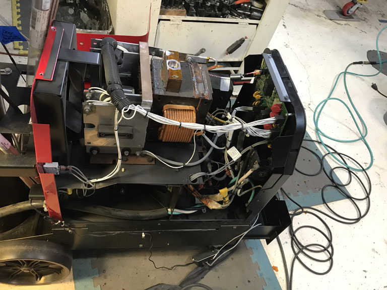
Worse yet, depite my previous love for Lincoln Electric, I fear I'm on the verge of a bad break up.
Lincoln Customer Service / Tech Support has proven themselves to be absolutely useless over the course of this past week.
My welder is now ramping up to about 80A-100A immediately after starting the arc. Of course this blows major holes in sheetmetal. It does the same thing regarless of what Amptrol is attached to it. It appears that it is a control board issue. The replacement board is about $900. Keep in mind that is 1/3 the cost of a new machine. Several calls to local welder repair shops seem to indicate that they belive it is a board issue but of course they can't confirm that without me schlepping a ~ 400lb machine to and from thier shop. I no longer have a utility trailer so any schelpping would involve a U-haul rental and even more wasted time.
For it's part, Lincoln Electric hides the detailed board schematics and any technical block diagrams of the board theory of operation behind their website which is only accessible if your a Lincoln Dealer or Authorized Repair Shop.
To make matters worse, the board is heavily potted on once side with the usual rubbery potting coupound. The other side has what appears to be an epoxy dip coating. This basically renders the board unserviceable according to a couple of the shops that I found that repair other boards for Miller, Hobart, ESAB, etc. I sort of get this from a reliability standpoint, these coatings shield the board from metallic dust and debris that could otherwise wreak havok. But come on. No once will touch the damn thing! One repair shop said they would try for $100/hr diagnostics & repair time and materials but no gurantee. 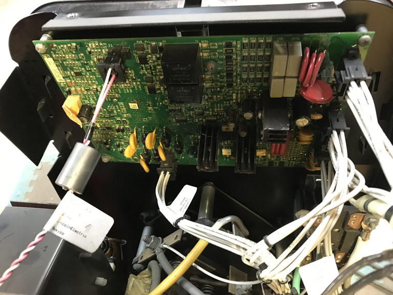
So I've ordered a replacement board but ouf course it isn't here yet. In fact they haven't even charged my card yet which makes me wonder if the company I ordered it from is having trouble getting it from Lincoln Electric.
Moral of the story, my next welder will be blue instead of red.
I guess I'll switch gears and do some work on engine cases, bearing fits, etc.
Posted by: mb911 Sep 5 2020, 08:12 AM
Well, Labor Day weekend is here. I had big plans to get a big chunk of sheetmetal work done. Unfortunately life doesn't work that way.
My beloved Lincoln Precision TIG 225 has taken a dump.
Worse yet, depite my previous love for Lincoln Electric, I fear I'm on the verge of a bad break up.
Lincoln Customer Service / Tech Support has proven themselves to be absolutely useless over the course of this past week.
My welder is now ramping up to about 80A-100A immediately after starting the arc. Of course this blows major holes in sheetmetal. It appears that it is a control board issue. The replacement board is about $900. Keep in mind that is 1/3 the cost of a new machine. Several calls to local welder repair shops seem to indicate that they belive it is a board issue but of course they can't confirm that without me schlepping a 400lb+ machine to and from thier shop.
For it's part, Lincoln Electric hides the detailed board schematics and any technical block diagrams of the board theory of operation behind their website which is only accessible if your a Lincoln Dealer or Authorized Repair Shop.
To make matters worse, the board is heavily potted on once side with the usual rubbery potting coupound.
The other side has what appears to be an epoxy dip coating. This basically renders the board unserviceable according to a couple of the shops that I found that repair other boards for Miller, Hobart, ESAB, etc. I sort of get this from a reliability standpoint, these coatings shield the board from metallic dust and debris that could otherwise wreak havok. But come on. No once will touch the damn thing! One repair shop said they would try for $100/hr diagnostics & repair time and materials but no gurantee. So I've ordered a replacement board but ouf course it isn't here yet. In fact they haven't even charged my card yet which makes me wonder if the company I ordered it from is having trouble getting it.
Moral of the story, my next welder will be blue instead of red.
I guess I'll switch gears and do some work on engine cases, bearing fits, etc.
Oh man don't go blue.. The same issues.. Lincoln does pretty good job on their machines.. We had 12 millers at school recently come in new in the box and all 12 boards were shot before even able to use the machines once.. Let me know if you need any help with Lincoln.. I am a national trainer for them and NC3 so I have some really great contacts there
Posted by: Superhawk996 Sep 5 2020, 08:27 AM
Oh man don't go blue.. The same issues.. Lincoln does pretty good job on their machines.. We had 12 millers at school recently come in new in the box and all 12 boards were shot before even able to use the machines once.. Let me know if you need any help with Lincoln.. I am a national trainer for them and NC3 so I have some really great contacts there
@http://www.914world.com/bbs2/index.php?showuser=9892
Thanks for the offer for help Ben. I may take you up on that. I'm going to check some of the big wirewound resistors this weekend that contribute to the the Micro Start circuit and/or Stabilizer Bypass and then just wait for a board hoping that does the trick. Unfortunately at Lincoln I can't even seem to get in touch with a person that actually knows the TIG 225 with any level of detail other than what I can read for myself out of the owners manual. One customer service rep said he would have a Precision TIG 225 expert call me. No call. Of course for my own stupidity, I din't ask for a name and a direct phone # to said expert. Next week.!
I can't see the point in pitching the rest of the hardware over a bad board. In my mind the transformer based machines may be heavier than crap but the transformers rarely fail. A modern inverter sure looks appaling from a weight / transport standpoint.
I appreciate the insight on Miller before I do something rash!
So many of our Industrial Giants have simply gone to a throw away mentality, it really makes me sad. To say the least, am I really supposed to scrap the whole rest of the chassis and transformers just beause a Printed Circuit board failed.
Posted by: mb911 Sep 5 2020, 08:43 AM
Oh man don't go blue.. The same issues.. Lincoln does pretty good job on their machines.. We had 12 millers at school recently come in new in the box and all 12 boards were shot before even able to use the machines once.. Let me know if you need any help with Lincoln.. I am a national trainer for them and NC3 so I have some really great contacts there
@http://www.914world.com/bbs2/index.php?showuser=9892
Thanks for the offer for help Ben. I may take you up on that. I'm going to check some of the big wirewound resistors this weekend that contribute to the the Micro Start circuit and/or Stabilizer Bypass and then just wait for a board hoping that does the trick. Unfortunately at Lincoln I can't even seem to get in touch with a person that actually knows the TIG 225 with any level of detail other than what I can read for myself out of the owners manual. One customer service rep said he would have a Precision TIG 225 expert call me. No call. Of course for my own stupidity, I din't ask for a name and a direct phone # to said expert. Next week.!
I can't see the point in pitching the rest of the hardware over a bad board. In my mind the transformer based machines may be heavier than crap but the transformers rarely fail. A modern inverter sure looks appaling from a weight / transport standpoint.
I appreciate the insight on Miller before I do something rash!
So many of our Industrial Giants have simply gone to a throw away mentality, it really makes me sad. To say the least, am I really supposed to scrap the whole rest of the chassis and transformers just beause a Printed Circuit board failed.
Send me an email and I will send you Dan's info
Posted by: bbrock Sep 5 2020, 10:58 AM
Oh no! That truly sucks. I'm feeling better about my ancient little Hobart. I don't think there is a single PCB to be found in it - not even a little switch circuit. Of course, they are owned by Miller now but not when it was built. I sometimes drool over the thought advancing to a nice modern Miller or Lincoln but maybe I'm better off.
The power woodworking tool industry is even worse for racing to the bottom. Most of the old major brands have been bought out at least once by conglomerates and chopped up into pieces. Even Delta bit the dust. Finding parts for tools more than a few years old is nearly impossible. One reason I gravitate to Makita is because I can still easily find parts for 30 year old tools. It's weird because in some ways power tools have never been better and more affordable, but there is no commitment to the customer any more. Like you said, throw away culture.
Good luck getting the welder repaired. Sorry it happened at the beginning of a long weekend.
Posted by: mb911 Sep 5 2020, 10:59 AM
Funny thing is miller is owned by ITW and Lincoln is still family run which is amazing to me
Posted by: Superhawk996 Sep 7 2020, 07:55 AM
The aftermarket bearing vs. Porsche OEM bearing saga continues.
I ordered two half shells at about $45 each that serve as main bearings for bearings #2 through #7.
I was hoping that they would measure a little tighter than aftermarket Glyco as bearing #1 half shells did.
Nope. Well, maybe by 0.0001" - 0.0002" but I was hoping for something significant.
OK - Time to put the Porsche OEM bearing vs Glyco aftermarket thing to bed.
The OEM Porsche bearings did reduce clearance by 0.001" vs. the aftermarket Glyco.
Recall I had a OEM bearing #1 and a pair of shells for bearing #2 -7. I put the OEM 1/2 shell bearings in postions #1 & #7 and then rechecked with Red Plastigauge for 0.002" - 0.006" this time given that I had some Green (.001" - 0.003") that didn't seem to compress fully when I did this the last time around.
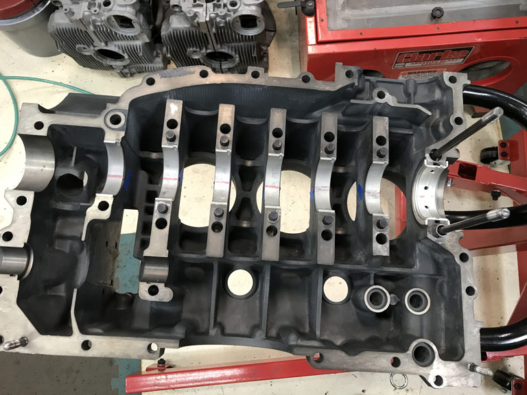
Results - Bearing #1 and #7 running at 0.003".
Number 7 Porsche OEM
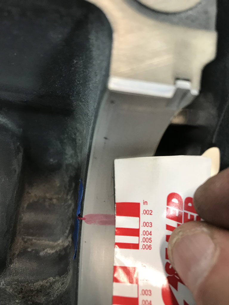
Number 1 Thrust Bearing Porsche OEM
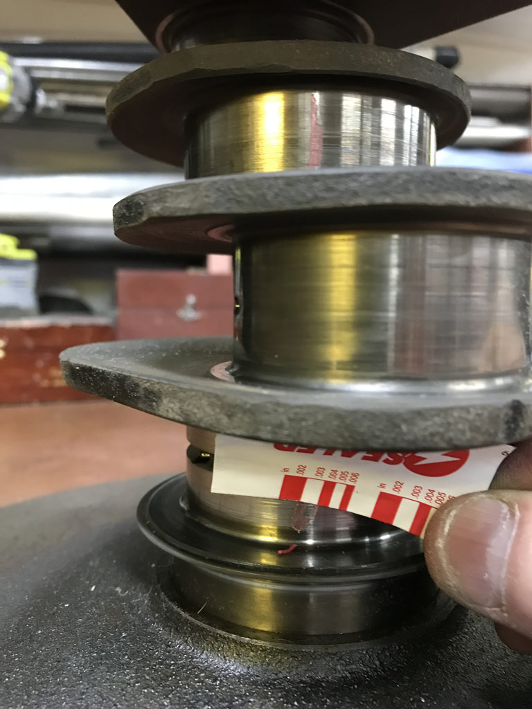
Number 2 thru 6
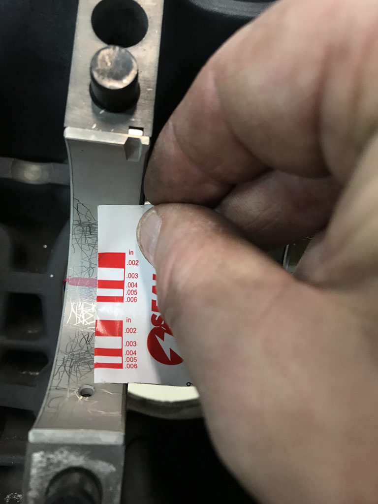
The good news is that all the rod clearances are looking good. Tightest was 0.001" and the other five were 0.0015" - 0.002" trending the tighter end at 0.0017" - 0.0018" or something like that (would need to measure with the bore gauge to know exactly).
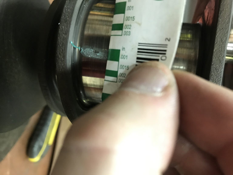
I now feel really confident that both the digital bore indicator method and the Plastigauge are in agreement that the Glyco bearings were giving me right around 0.004" of clearance (too much).
Bottom line, crank is going to have to go to Ollies to have the mains ground 0.010" under and to see if they can just put a light (0.0001" - 0.0002") polish put on the rod journals.
Posted by: 914_7T3 Sep 7 2020, 01:46 PM
Progress is good!
Posted by: Superhawk996 Sep 12 2020, 04:16 PM
Praise the Lord! Welder is fixed.
Many thanks to Ben for his advice and also for hooking me up with a knowledgable contact within Lincoln.
I wish I could say it was something simple but that didn't happen.
After having thouroughly checked out the basics like wiring and checking a couple of the big wire wound resistors, capacitors, adjusting the high frequency start point gap, and bunch of other stuff the only thing really left was the board.
Conversation with Ben's Lincoln contact convinced me that it was time to open the box with the high dollar circuit board that becomes unreturnable once opened.
Turns out that was the fix.
Laid down several good beads on .039" sheetmetal without blowing the HUGE holes that had previously occurred when the welder would surge the current uncontrollably at the start or end of a bead.
The unfortunate thing is no one can explain why the board went bad. As a former electronics tech, I've seen it happen before. Failure without explanation. Sometimes it just happens to circuits with fancy silicon in them. It sure aggravates me when I can't find a root cause though! New board is a revised Revision level so Lincoln certainly changed something on the board but no way to know what it was. Could be a transistor they can no longer get . . . or it could be that they changed a transistor that was operating too close to it's limits and had a penchant for failing. No way to know.
I'll keep my fingers crossed this board lasts at least 10 years like the 1st.
Back to on the car tomorrow.
Posted by: mb911 Sep 12 2020, 04:21 PM
I am glad that Dan could help.. He bleeds lincoln so he is the guy to ask.
Posted by: Superhawk996 Sep 17 2020, 10:56 AM
Quick post. Been super busy and not much time to spend welding. Hoping for better this weekend.
Spent some time filling the holes that got blown when welder 1st stareted acting up. Still have a couple more that need attention.
Cut a 4mm thick strip to fill the gap between the two panels and then got it pasted in position using a 0.040" tungsten and .035" MIG wire as filler rod. All done at very low current to hold it together temporarily with temporary tack welds largely just sitting on top.
Will use a copper backer this weekend and get the whole thing sewn together without blowing out the 4mm filler. 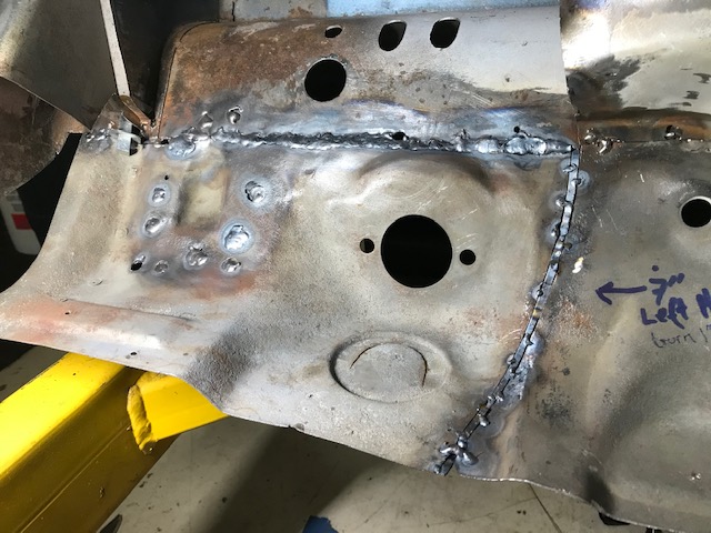
The whole area that sits below the brake reservoir then needs to be Ospho treated to address that surface rust before I put the flap back in place.
Posted by: Superhawk996 Sep 19 2020, 05:15 PM
Closing in on the worst of the pedal box area. It is just such a pain in the butt to work on this area without a rotiserrie. The wiring harness is tie wrapped up to the steering column mount and it is constantly touching or snagging my welding helmet.
Got the area with the 4 mm filler burned in. 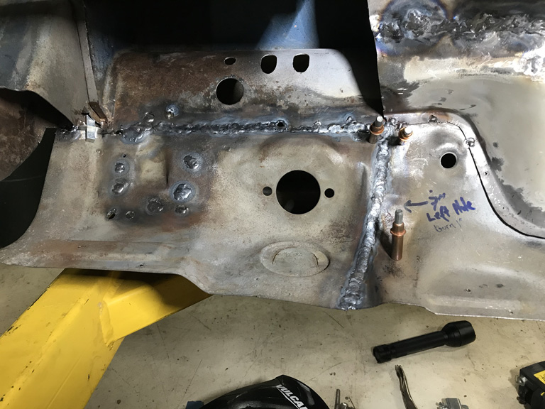
Used a copper backer that was held into place to help ensure good penetraiton and complete fusion of the 4 mm filler without burn through. 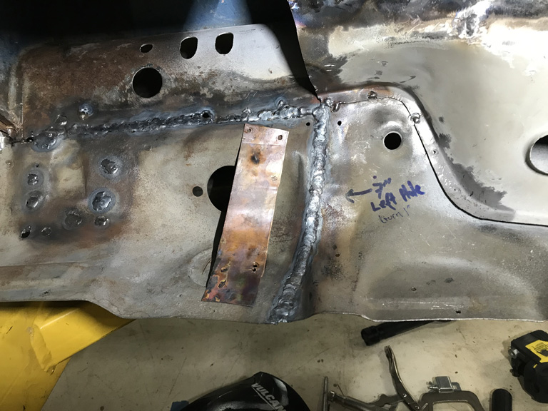
Totally happy with the penetration. Strong as the base metal. 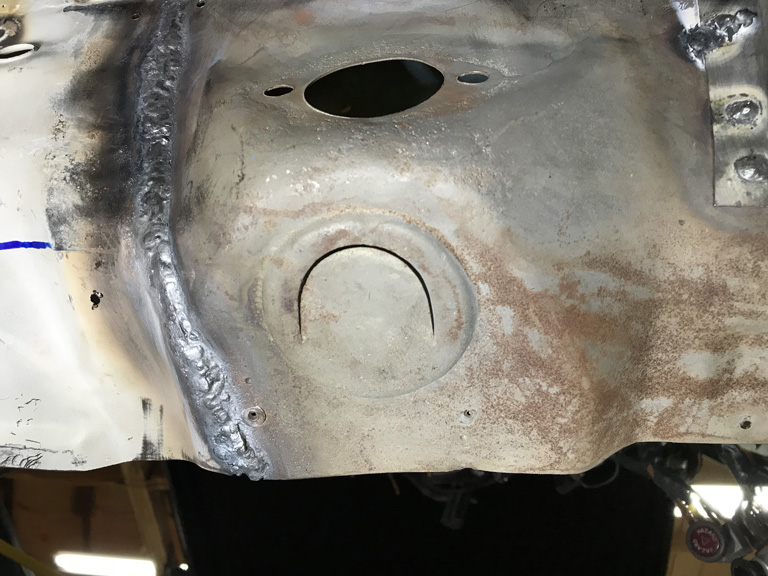
Then finished things off by filling the holes blown by the bad welder and making sure I had good weld penetration across the top. 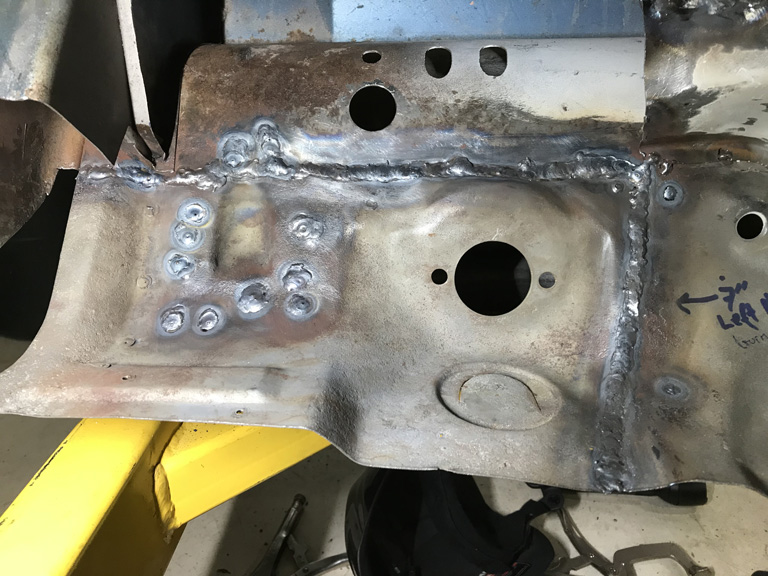
Dabbed some Ospho onto all surfaces. We had a bunch of humidity here that put a light surface rust on the panel. That will get the surface rust up under the tank area under control too.
Did a quick check of the suspension point vs. my reference point on the floor and movement of was only about 1 mm which is awesome.
Next up. Put the tuna can flap back and then attack the section of the wheel house that had to be removed.
Posted by: Superhawk996 Sep 21 2020, 06:12 AM
Well rather than put the tuna can flap back, I decided to get started on the work.
There were still remnants of fiberglass and epoxy resin that needed removing. Let me say that there is a special place in hell for those that use fiberglass to "repair" sheetmetal rather than man up and do it properly.
In the process of getting the last of the resin off the driver longitudinal, I found this nice stress crack. Not unheard of to have stress cracking here, but, I'll contend that someone drove this car around for quite a while with the passenger long completely roached and not able to bear it's fair share of the structural burden. 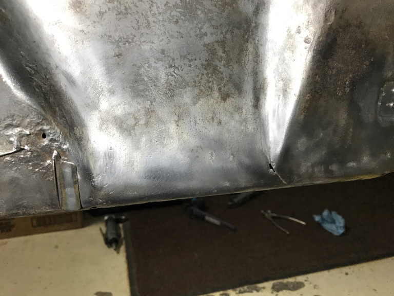
Since weekends have a way of disappearing too fast, I didn't get far with the wheel house but I was able to begin to trim away the donor sheetmetal. 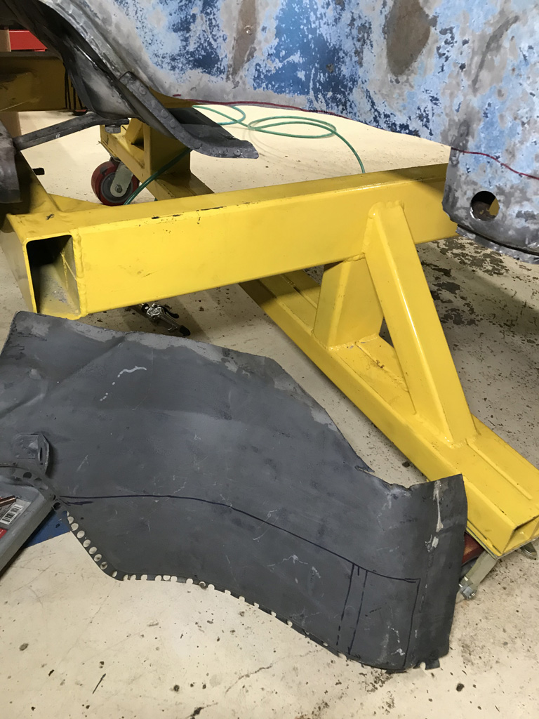
Rough mockup 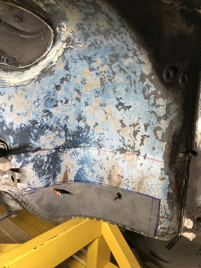
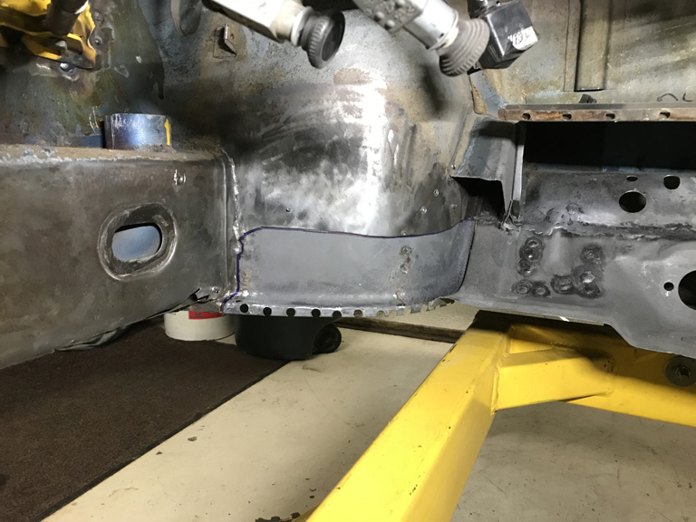
Maybe with a little luck this week I can get the final fitup done and get this tacked in before the weekend.
Posted by: Superhawk996 Oct 12 2020, 10:59 AM
Finished up the peal box area. What a PITA.
Front firewall / bulkhead sheetmetal is only about 0.030" which would be hard enough to weld but add a little surface rust on the backside and difficult access and it's a recipie for just blowing holes. 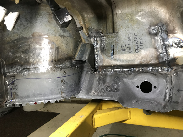
Copper backers cleco'd in place made it doable but I'm just glad to be done with this area. Final step is to use a shrinking wheel to suck out a little bit of the oil cannning that got created when the tuna can flap was bent up and out of the way. Bending the sheetmetal stretches it ever so slightly and shrinking it is the only way to get it back.
Attached image(s)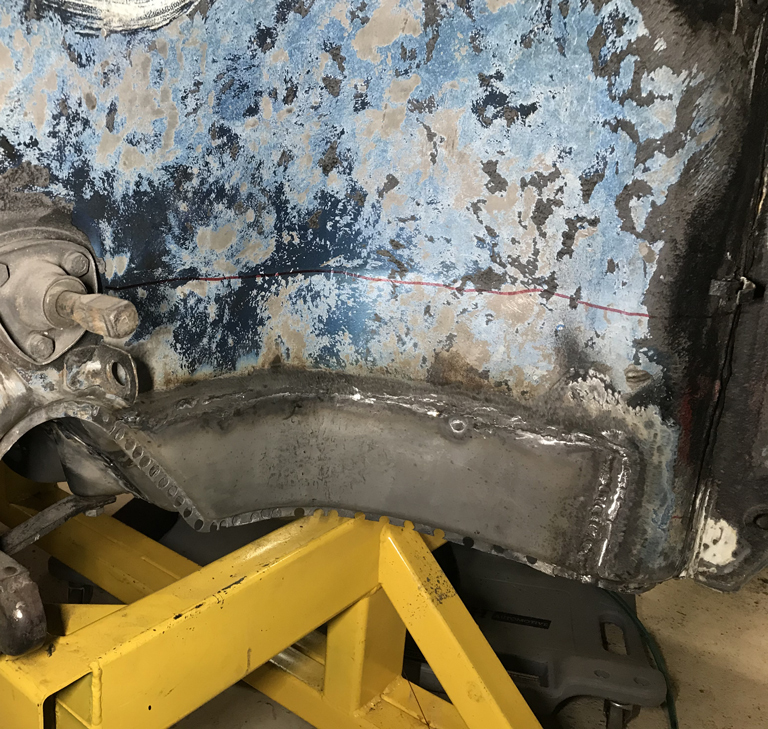
Posted by: Gint Oct 12 2020, 03:59 PM
2 years seems more like twenty minutes any more.
Ambitious project, but you're getting right to it.
This is another thread I'm going to have to take the time to read all the way through.
Posted by: Superhawk996 Nov 29 2020, 08:06 PM
November wasn't terribly productive since I was traveling for a couple weeks.
Manged to get the area under the gas tank cleaned up, seam sealed and laid down a light coat of primer to keet it all from surface rusting. 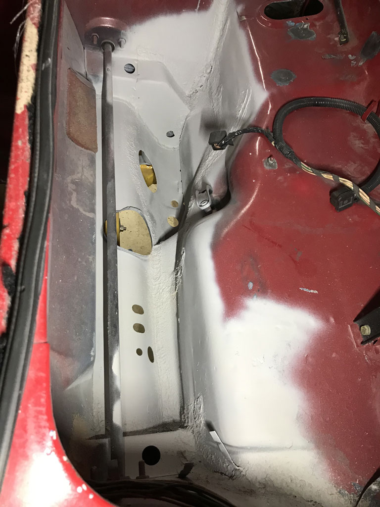
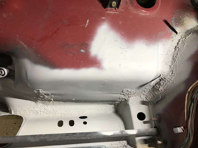
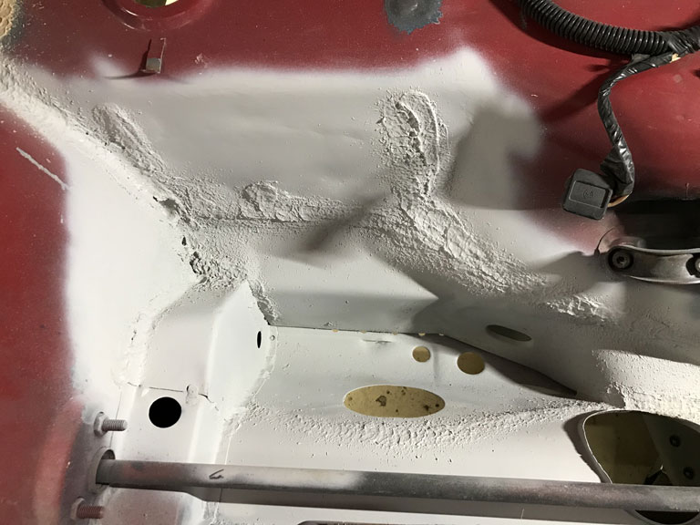
and did same for interior side. 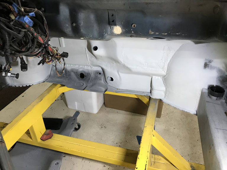
Then turned my attention toward the fun work of overhead welding in the driver side longitudinal patch to fill in the area that I cut out because it was rusted and it also allowed access to get the sand out of the driver side long. 
Brazed the parking brake cable tubes to the rear bulkhead. 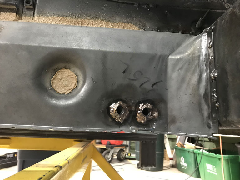
A good chunk of time has been spent playing with other miscellaneous parts. Lots of ultrasonic cleaning of fasteners and engine parts in anticipation of a rebuild this spring.
And of course a simple job like just wanting to swap the rear caliper adjusting screws over from my old calipers to the new PMB calipers was 50/50. One was super easy. the other of course was stuck and pre-stripped. Not a hard project but easily a hour detour trying to get the 4mm hex cap off. Finally resorted to the old welding tricks.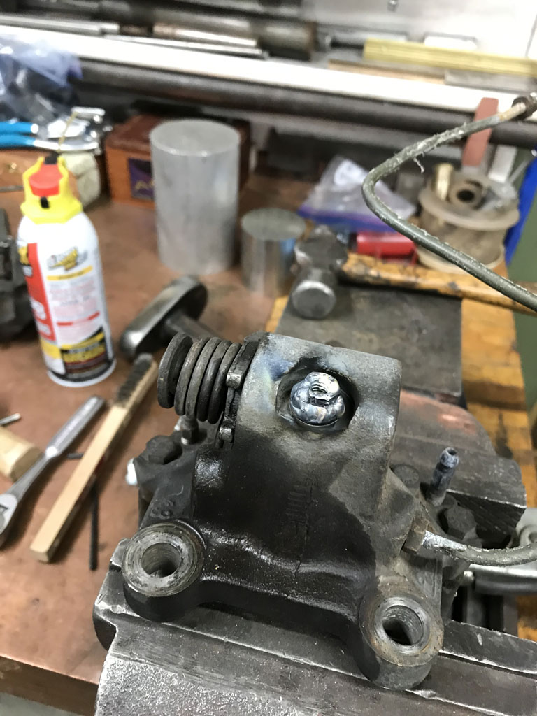
Bugger
Here's to hoping for a more productive December.
Posted by: Jett Nov 29 2020, 10:50 PM
Phil, just read this entire thread and was amazed by the passion and skill!
Can’t wait to see this one on the road!
Posted by: bbrock Nov 30 2020, 08:58 AM
Nice work! That peddle area is not a fun place to work so I'm sure that feels good to have it done, and done well. I can sure relate to the hours spent trying to get a stubborn nut or bolt loose Looking forward to the December progress.
Posted by: Superhawk996 Dec 12 2020, 07:26 PM
Driver side long is finally all prepped. 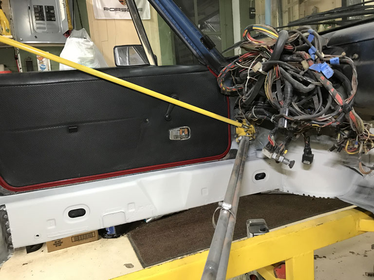
Rust repaired at the front edge with a patch, pinhole performations that got started under the fiber glass matt are filled. Who would think rust would start from inside the car!
Stress crack at the hand brake divot was welded up. The entire long was treated with Ospho twice - wire wheeling out any neutralized rust twice. Finally prepped for a coat of epoxy primer to keep it from flash rusting in the future.
Left an unpainted track where the new floor pan welds in. 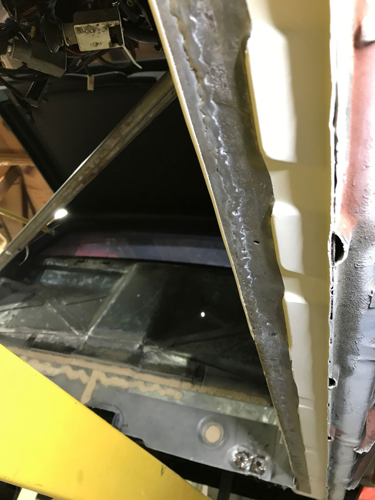
At this point, I'll start prepping the floor pan for welding tomorrow. Excited to be getting close to the milestone of having floor pans installed.
Posted by: Superhawk996 Dec 12 2020, 07:30 PM
The other exciting project for the day was inspecting and trial fitting a freshly ground crank from Ollies to see if the bearing clearance issues is fixed.
Remember from the last installment of the crank saga that I had bearing clearances that were at 0.004"+ and the OEM bearings didn't quite get it there.
Crank went to Ollies to take the mains and rods to 0.010" under and for the rest of the complete spa treatment (Magnaflux, heat treat, balancing, micropolish, etc.).
Initially checked it for straightness as a double check post heat treat.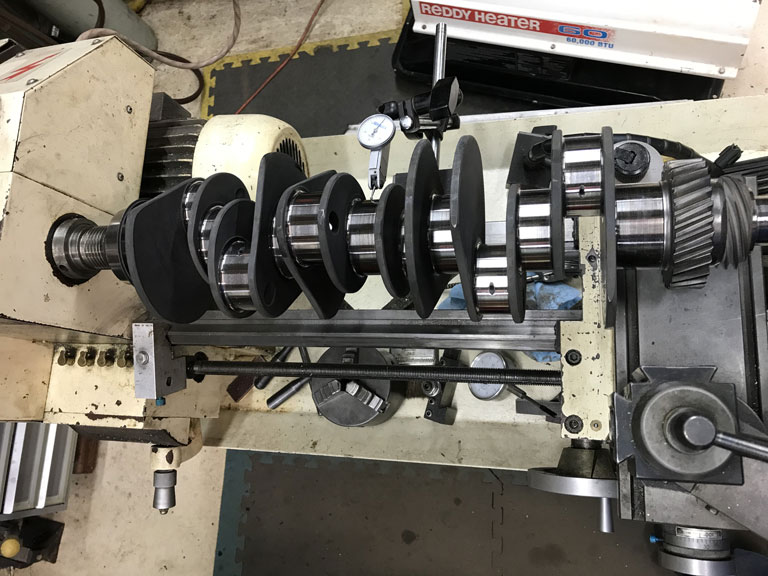
Then checked all journals on a go/no-go basis using gauge blocks to set up my micrometer. Then measured mains to get an idea of where they are at. Mostly running at 2.2334" vs spec of 2.2331" - 2.2338". Sweet.
Then used plastigauge to check clearances. OEM 0.010" undersize bearings are used across all bearings. 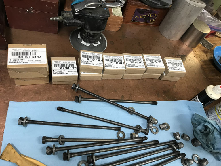
Bearing #7 is now at 0.002" and Bearing #1 is between 0.0015"-0.002". Huge improvment. 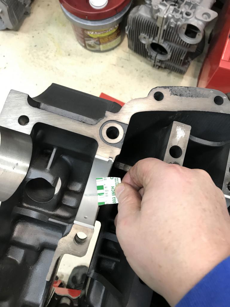
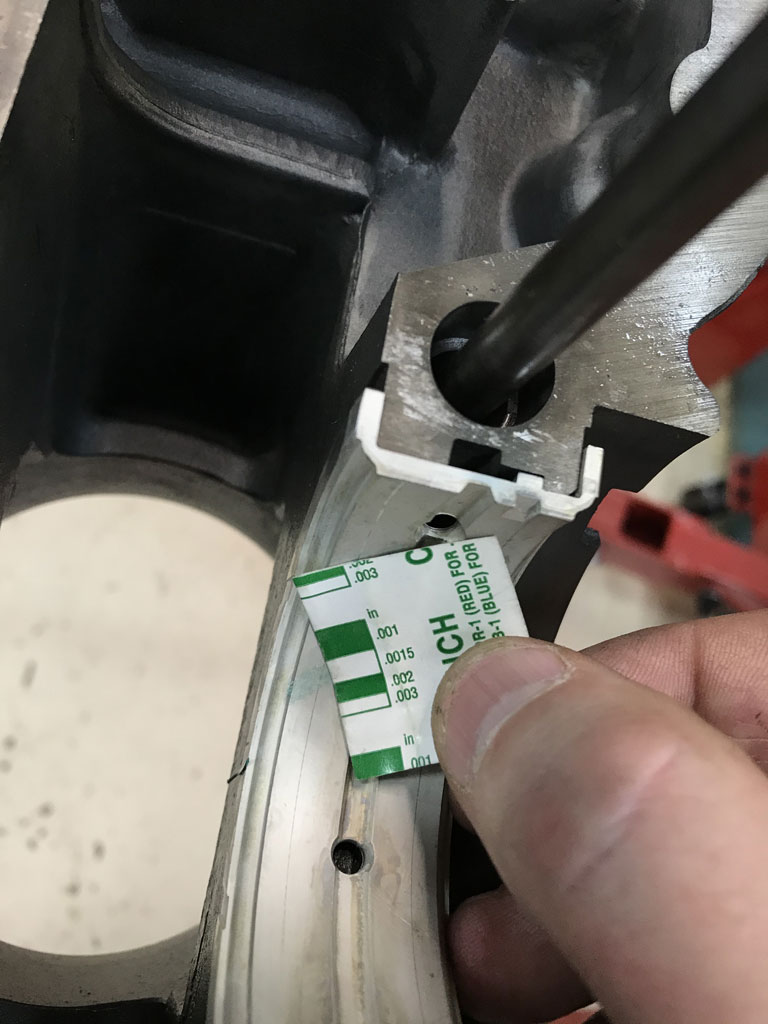
With good uniformity across all the rest of the bearings with absolutely no more than 0.003" clearance anywhere. Spec is 0.0011" - 0.0028". Success 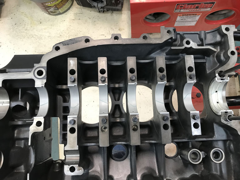
Unfortunately Ollies was unable to directly source the OEM rod bearings to me. Still waiting on those before I can plastigauge the rods.
Posted by: bbrock Dec 13 2020, 10:38 AM
Nice work straightening out those crank clearances. Good to have that behind you.
Excited to see that floor pan go in. I think that was the most momentous milestone for me in my entire build. It was the moment when a rusted out heap of scrap became a solid chassis in my mind.
Posted by: Superhawk996 Dec 21 2020, 07:49 AM
Rod bearings arrived just in time for the weekend.
Ollies Recommended Clevite 77 bearings which I purchased directly from thier supplier. Clevite is a subdivision of Mahle. These bearings have a Calico CT-1 dry film coating that is about 0.0003" thick. They are promoted as a race bearing which usually I wouldn't be game for but my thought was that they are still a Clevite 77 tri-metal bearing underneath. Worst thing should be that the dry film wears away, opens up clearance by 0.0003" and I'm no worse off. Asuming that I have good clearances to start with. As an added bonus they are substantially cheaper than Porsche OEM Rod bearings. Quick check of the bird forum shows quite a few successful users of Clevite bearings in 911 engines as a double check to Ollies recommendation. 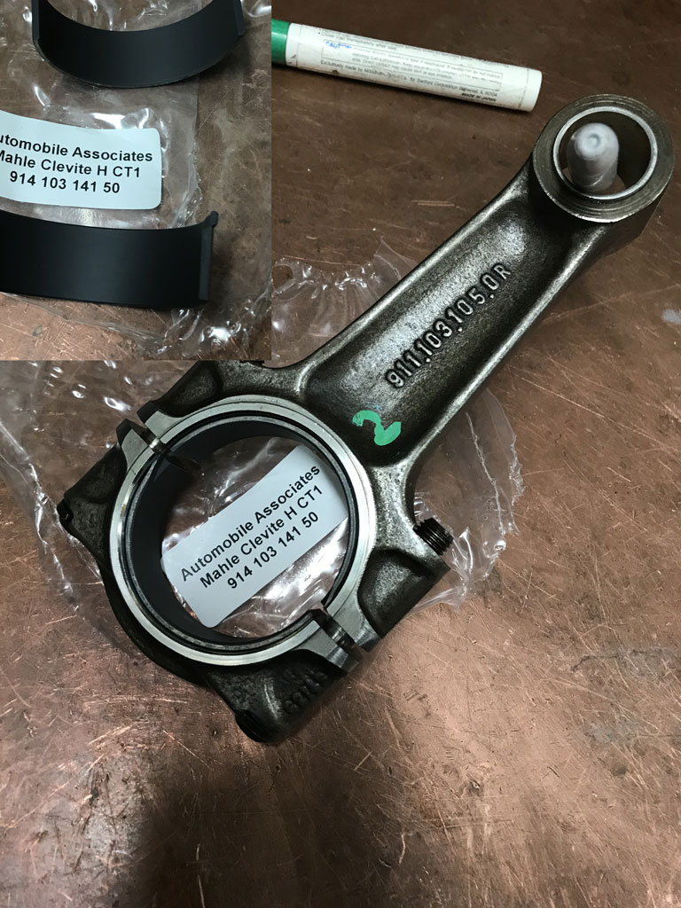
Spent pretty much a decent 8 hour day just trial fitting rod bearings and doing a mock assembly on the mains bearings. Last time I did the mains, I was only checking clearances and forgot to reassemble the crank and just give it a spin. At this point I'm getting sort of tired of removing, installing, and torquing the 11 case though bolts 13 acorn fasteners and the worst one that is hidden inside the cam chain area!
So the rod bearings worked out great.
All rods came up at 0.002" clearance with spec being 0.0011" - 0.0034". Perfect! 
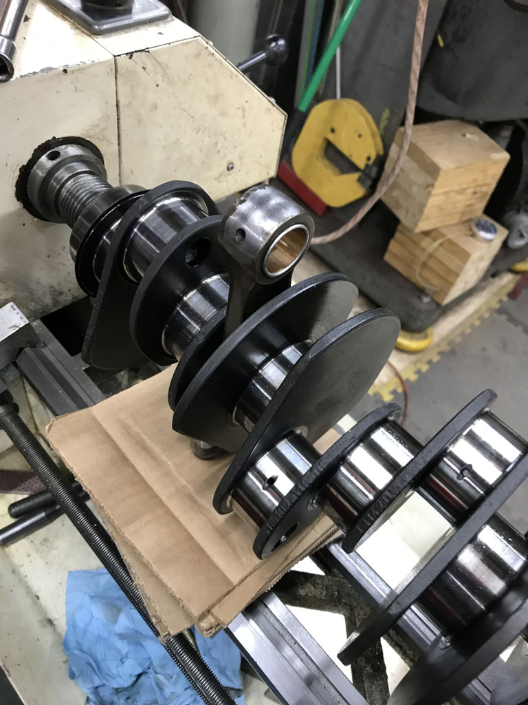
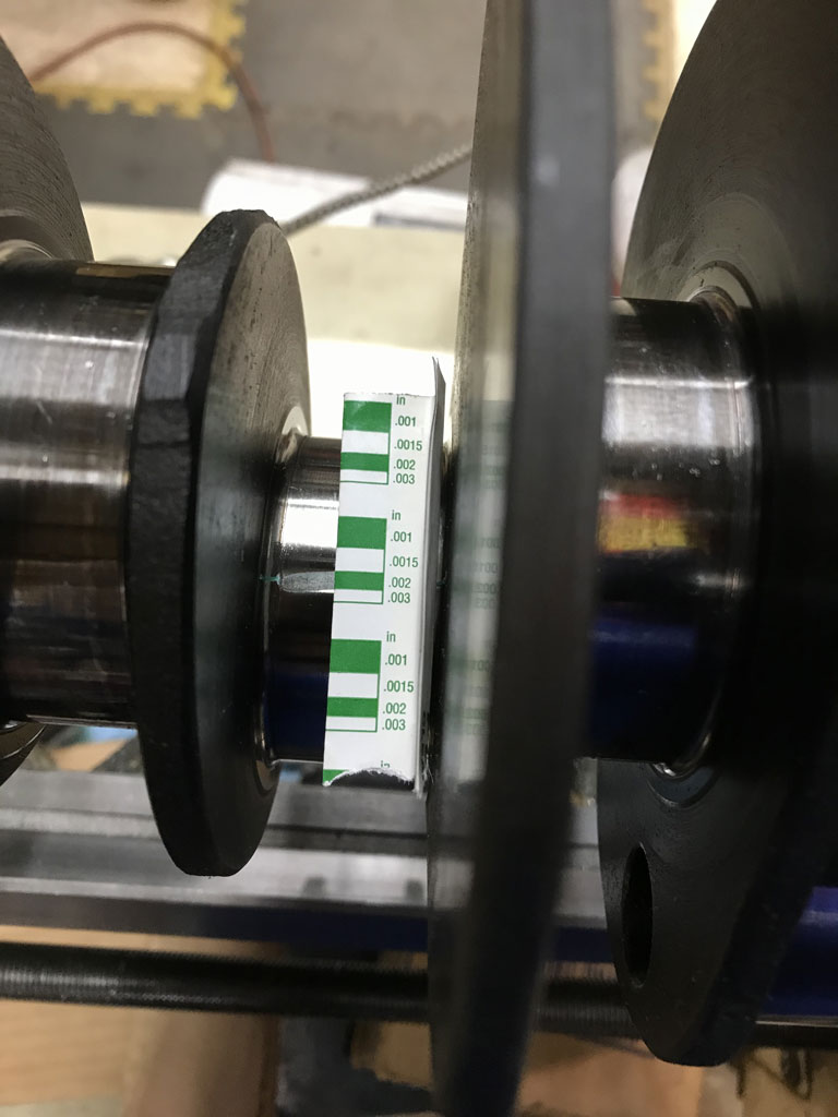
Then I moved on to mock up the whole crank into the case to make sure there are no assembly issues that would lead to binding or tight spots.
Thankfully no issues but watching Ian's video a few weeks back of the Bumblebee motor binding after a line bore sure had me a bit apreshensive. Thankfully - no issues. Crank rotated perfectly with only light hand force.
https://www.youtube.com/watch?v=x1rovlniCLo
At this point I'm so relieved to have the bottom end fully sorted. 
Posted by: mb911 Dec 21 2020, 08:25 AM
Rod bearings arrived just in time for the weekend.
Ollies Recommended Clevite 77 bearings which I purchased directly from thier supplier. Clevite is a subdivision of Mahle. These bearings have a Calico CT-1 dry film coating that is about 0.0003" thick. They are promoted as a race bearing which usually I wouldn't be game for but my thought was that they are still a Clevite 77 tri-metal bearing underneath. Worst thing should be that the dry film wears away, opens up clearance by 0.0003" and I'm no worse off. Asuming that I have good clearances to start with. As an added bonus they are substantially cheaper than Porsche OEM Rod bearings. Quick check of the bird forum shows quite a few successful users of Clevite bearings in 911 engines as a double check to Ollies recommendation.
Spent pretty much a decent 8 hour day just trial fitting rod bearings and doing a mock assembly on the mains bearings. Last time I did the mains, I was only checking clearances and forgot to reassemble the crank and just give it a spin. At this point I'm getting sort of tired of removing, installing, and torquing the 11 case though bolts 13 acorn fasteners and the worst one that is hidden inside the cam chain area!
So the rod bearings worked out great.
All rods came up at 0.002" clearance with spec being 0.0011" - 0.0034". Perfect!
[attachmentid=773658]
Then I moved on to mock up the whole crank into the case to make sure there are no assembly issues that would lead to binding or tight spots.
Thankfully no issues but watching Ian's video a few weeks back of the Bumblebee motor binding after a line bore sure had me a bit apreshensive. Thankfully - no issues. Crank rotated perfectly with only light hand force.
https://www.youtube.com/watch?v=x1rovlniCLo
At this point I'm so relieved to have the bottom end fully sorted.
1 tip I will give you is to buy the RSR rocker shaft seals.. I am now doing that in my engine over the winter.. Remember zero miles on my engine.
Posted by: Superhawk996 Dec 21 2020, 08:48 AM
1 tip I will give you is to buy the RSR rocker shaft seals.. I am now doing that in my engine over the winter.. Remember zero miles on my engine.
@http://www.914world.com/bbs2/index.php?showuser=9892
Only 1 tip for free? Will definately do the RSR seals as belt and supenders approach! Rocker shafts. So much yet to be done. I haven't even cleaned & inspected my rocker shafts yet. I rember thinking that I probably was going to have to replace a few of the fasteners and/or the conical jambs. I guess we will see how they clean up and/or how pitted they are from corrosion. Still on purchse list:
P&C's -- contemplating Nickies for weight save and way to push up C.R. a bit.
Cams -- engine was CIS so I need E spec cams.
New Oil Cooler -- Ollies was unable to clean the OEM part that came off this engine.
Contemplating a new 4 rib pump -- just in case I need to go external cooler later (remember that C.R. bump?) but I'm really not wanting to mount an external cooler.
Induction & EFI.
Let's face it, this engine won't be installed & running for a long time!
Plan is to put 2.0L four in 1st while I sort out the nuances of the 2.4L six build and conversion.
Posted by: mb911 Dec 21 2020, 08:54 AM
1 tip I will give you is to buy the RSR rocker shaft seals.. I am now doing that in my engine over the winter.. Remember zero miles on my engine.
@http://www.914world.com/bbs2/index.php?showuser=9892
Only 1 tip for free? Will definately do the RSR seals as belt and supenders approach! Rocker shafts. So much yet to be done. I haven't even cleaned & inspected my rocker shafts yet. I rember thinking that I probably was going to have to replace a few of the fasteners and/or the conical jambs. I guess we will see how they clean up and/or how pitted they are from corrosion. Still on purchse list:
P&C's -- contemplating Nickies for weight save and way to push up C.R. a bit.
Cams -- engine was CIS so I need E spec cams.
New Oil Cooler -- Ollies was unable to clean the OEM part that came off this engine.
Contemplating a new 4 rib pump -- just in case I need to go external cooler later (remember that C.R. bump?) but I'm really not wanting to mount an external cooler.
Induction & EFI.
Let's face it, this engine won't be running for a long time!
I would not do nickies unless you are set on track.. I have cast iron with nikisal lining done by melenium and that sure saves a bunch of money. As far as rockers and shafts contact Craig Garrett he is in MI and has done, heads, rockers etc for me for the last 15 years. Then for oil pump just have your pump modified for improved flow. I believe that is about $250 from Supertec to have that done..
Posted by: Superhawk996 Dec 21 2020, 09:23 AM
Not intended for track but I'm all about keeping the weight of the /6 conversion down for for improved handling and the weight/HP ratio low so I can at least keep up with a 2020 Toyota Camry (0-60 ~5.8 sec) .
Plus, how can you resist jewelry like this? 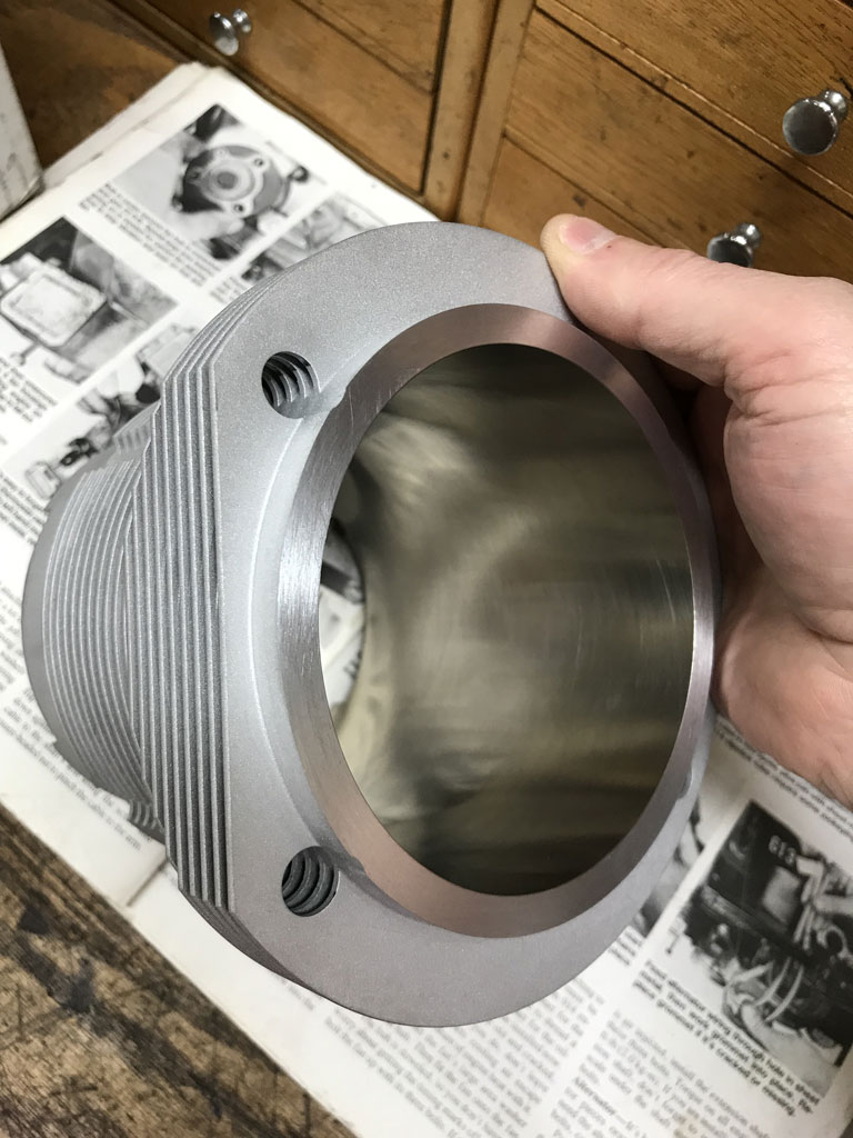
These are 100mm and slated to go toward GA004310. GA000099 stays 2.0L stock.
Posted by: Superhawk996 Dec 21 2020, 09:47 AM
In addition to the 2.4L engine work I was also able to get the driver side floor pan trimmed and tacked into position.
Prior to welding in the floor pan, I wanted to get another round of body measurements to make sure things hadn't moved around too much with the pedal box area repair.
Things are pretty much the same as the last two measurements. Minor improvement in the cross car diagonal that came about from relocating the rear most driver side attachement point as part of the pedal box repair. 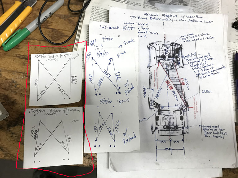
Here is the driver side floor, not yet fully installed. Since I chose not to go the rotisserie route, I'm having to do all welding overhead. Although not overly difficult, it does lead to a sore neck and shoulders after a while.
I think I counted something like 65-70 hole punches when I was prepping the panel. I probably only got about 15 of them puddle welded this weekend.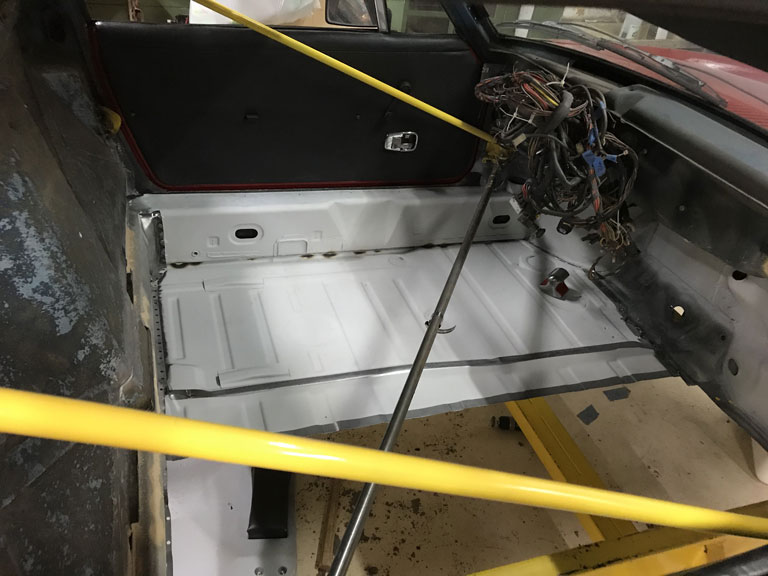
Next order of business is to rebuild the tunnel tubes. I belive the tunnel will need to be installed prior to the other 1/2 of the floorpan in order to be able to manipulate the tubes through the rear bulkhead exit holes.
I'm on vacation for the holiday starting this week so I hope to make some decent progress among time spent with friends and family. Plus I need to tear down a old tail shift trans for another member to have the case. Lots to do!
Posted by: 914werke Dec 21 2020, 11:00 AM
would you be interested in a complete scabbed tunnel, all lines intact?
Posted by: Superhawk996 Dec 21 2020, 11:11 AM
would you be interested in a complete scabbed tunnel, all lines intact?
@http://www.914world.com/bbs2/index.php?showuser=453
Thanks for the offer. Long ago I purchased a scabbed tunnel (lines cut) and it is pretty much all prepped to go in except for fabrication of the new tubes. I also already purchased the metric sized tube from RD so I'd be out all that coin and effort to change plans. Plus I intend to create a better attachement for the clutch tube to prevent ever having that break free in my lifetime.
Thanks for reading the post and reaching out to try to speed things up.
More than a few of your parts going into this build!
Recently received the throttle cable bracket that bolts to the case. Awesome work on those. Same for the bronze shift bushing. I'm looking forward to that helping get some of the slop out of the usual linkage play.
Posted by: mb911 Dec 22 2020, 11:08 AM
So will this be running this summer?
Posted by: Superhawk996 Dec 22 2020, 01:14 PM
@http://www.914world.com/bbs2/index.php?showuser=9892
Late summer or early fall with GA000099 2.0L engine is the goal.
My intent is to finish the floor structure (tunnel & cross braces) and then sort of slam it together just good enough to drive it some in the fall when the temps are enjoyable.
That might require just tacking some flat sheetmetal over the A/C condensor holes in the front trunk as short term solution.
Then when winter sets in, put it back up on the cart and finish the Frunk up along with some other minor non-structural repairs (like pinholes in rear bulkhead from rusting behind engine sound deadner. Could begin to think about the /6 conversion stuff at that point.
Really need to drive this little bastard. If you leave them on jack stands too long they get used to it and never come off them in pursuit of magical perfection
It's easy to lose sight of how many details and how much time it will take to put it back together from a tub. Last time I did it in 6 weeks including a quick paint job.
USAF in the late 80's decided I had 12 weeks to either reenlist or get out due to Gramm-Rudman Act reductions in armed forces. I wasn't supposed to separate for another 9 months. I said Fuch that. It was a good lesson in how Gov't lies, and cheats folks. If you want out early, too bad! That will come with a dishonorable discharge. If they want you out early for budget reasons . . . well no issues there. . . . off you go, no matter what your life plans were. Strangely, 30+ years later the Gov't is still Fuching people! Go figure.
It was a show becuase I had just torn my 914 down for paint to a bare tub minus all glass! Got er' done. But, I was in my 20's and I didn't get much sleep for 6 weeks!
Posted by: 930cabman Dec 24 2020, 08:37 AM
@http://www.914world.com/bbs2/index.php?showuser=9892
Late summer or early fall with GA000099 2.0L engine is the goal.
My intent is to finish the floor structure (tunnel & cross braces) and then sort of slam it together just good enough to drive it some in the fall when the temps are enjoyable.
That might require just tacking some flat sheetmetal over the A/C condensor holes in the front trunk as short term solution.
Then when winter sets in, put it back up on the cart and finish the Frunk up along with some other minor non-structural repairs (like pinholes in rear bulkhead from rusting behind engine sound deadner. Could begin to think about the /6 conversion stuff at that point.
Really need to drive this little bastard. If you leave them on jack stands too long they get used to it and never come off them in pursuit of magical perfection
It's easy to lose sight of how many details and how much time it will take to put it back together from a tub. Last time I did it in 6 weeks including a quick paint job.
USAF in the late 80's decided I had 12 weeks to either reenlist or get out due to Gramm-Rudman Act reductions in armed forces. I wasn't supposed to separate for another 9 months. I said Fuch that. It was a good lesson in how Gov't lies, and cheats folks. If you want out early, too bad! That will come with a dishonorable discharge. If they want you out early for budget reasons . . . well no issues there. . . . off you go, no matter what your life plans were. Strangely, 30+ years later the Gov't is still Fuching people! Go figure.
It was a
show becuase I had just torn my 914 down for paint to a bare tub minus all glass! Got er' done. But, I was in my 20's and I didn't get much sleep for 6 weeks!Wow, quite the build you have there. Good plan to bang it together and get some seat time this coming summer. Another confirmed crazy man. Keep up the good work and hold the line, you will be crossing the finish line before you know. Don't you just love Plastigage? so long as the clearances check out, the crank is reasonably straight and the crank spins by hand when the case is clamped, all is good.
Posted by: Superhawk996 Dec 27 2020, 07:10 PM
What started out as a simple plan to build out the tunnel has come with some complications.
Started out easily enough by adding a doubler to the braket that support the clutch tube. 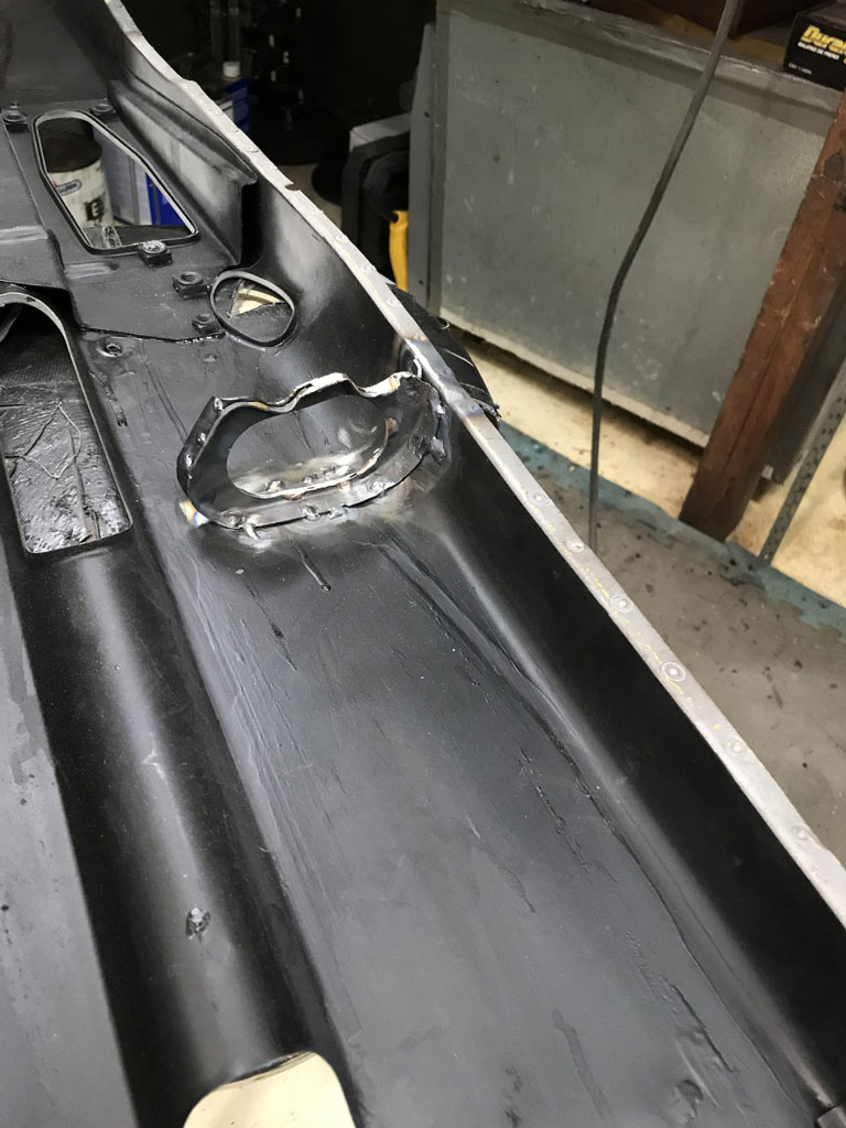
Fabrication of the clutch and throttle cable tubes was easy enough.
The problem arises trying to install the tunnel with the driver side floorpan in place. Although I was able to do it, I don't see how I can do it with the heater cable tubes installed into the tunnel.
The clutch and throttle cable tubes are as long as they can be while still allowing me to get the tunnel installed.
Here are the max length tubes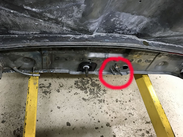
But from this other picture you get an idea of how long the tubes for the heater cables need to be. Oh so close, but, probably a smidge short. 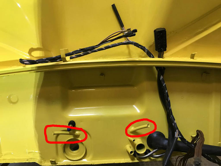
This left me in a bind. The driver side floor pan is tacked in about 12 places and will need to be removed. The heater cable tubes need to be installed with the Tunnel already installed. Since I'm not sure of the original VW build sequence, I can only assume that the tunnel (with tubes was installed) was installed before other parts like the rear bulkhead and/or the floorpan. Bummer.
So before I remove the floorpan to re-attack the tunnel heater cable tube problem, I figured I'd finish mocking up more of the floorpan to make install easier later on. Installed shifter to make sure tunnel is centered and that there is no binding of the shift rod as installed, etc. 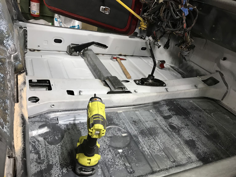
Tomorrow -- finish by mocking up the cross members and flanging them to the longs.
Then I may try one more attempt to come up with a way to install the tunnel with the heater cable tubes in place by ovaling out the exit holes for a bit more clearance. Extra clearance can be brazed up as long as it's not too large. If that fails, the driver side floorpan has to come out. Then I will need to do the heater cable tube install from underneath
Posted by: bbrock Dec 27 2020, 08:02 PM
Looks like you've had your own trials to handle this weekend. How fantastic would it be to have an assembly sequence manual! Can't count the number of times I've had to assembly things twice, or even thrice because I didn't really this thingy-mi-bob needed to go in first. What ever you end up doing, I know it will be done right. Looking good!
Posted by: Superhawk996 Dec 31 2020, 03:46 PM
File Under Two Steps Backward, One Step Forward.
First step backwards was removal of the driver side floor pan that was already puddle welded in more than a dozen spots. Removing spot welds is bad. Removing puddle welds is way worse. Not only in terms of the time it takes but also in the carnage it does to the panel. More on this later.
Fabricated the heater cable guide tubes that couldn't be fitted with the floor pan in place. Thought I had them close enough and brazed them into position.
All the aforementioned activity largely occured between 9pm and 1:30 am Tuesday night. Waking up the next morning my neck and back were so sore I took a day off to recover. Doing all this without a rotisserie is just masochism on my part. I still think I'm further ahead vs. stopping to build a rotisserie but I'm sure paying for it.
So after recovering I hit it again today.
Second step backward was having to un-braze the heater guide tubes and the throttle cable tube after finding they were sitting about 4-5mm too low preventing the floor pan from being reseated properly to the tunnel.
When I installed the tube bundle the other night, it was sitting about 4mm low in the tunnel bracket but being tired I figured there would be clearance. I thought filling the gap with braze wouldn't be an issue. I couldn't have been more wrong.
After un-brazing and then moving the bundle right into hard contact with the tunnel bracket, here is the clearance. The fuzzy grey on the bottom is the edge view of the driver floorpan. The tube in the foreground is the clutch cable tube, the one closest to the floorpan at the rear is the throttle cable tube. Just barely clears! 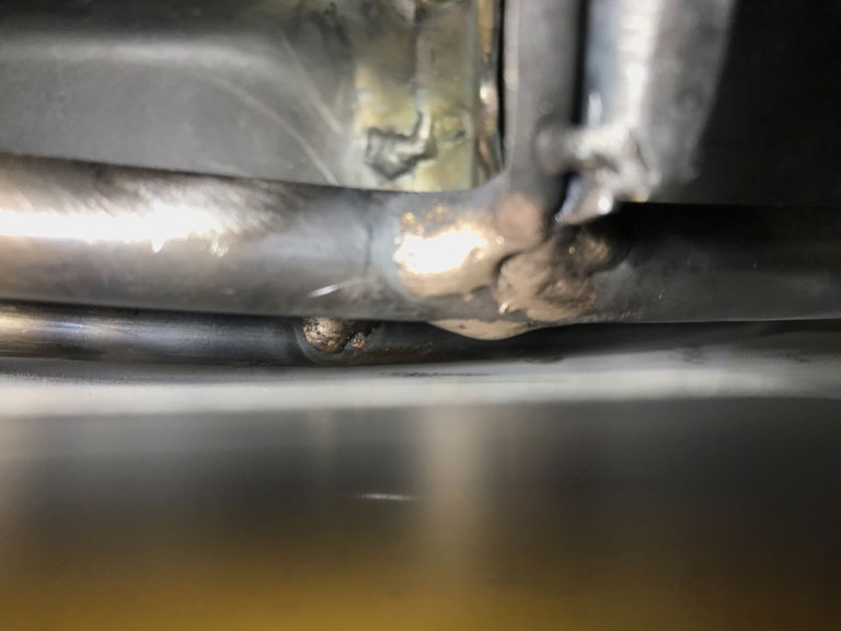
Tunnel lines fabricated, and brazed in proper postions.
After moving everything back to to be in hard contact with the bracket, it just barely clears with about 2mm of clearnace and the floor pan once again fits to the tunnel properly. One Step Forward.
Looking from rear: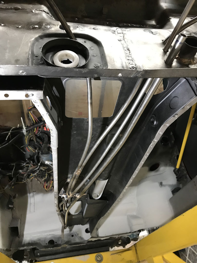
Looking from front: 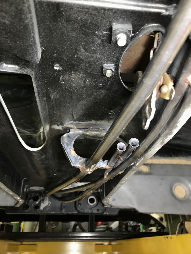
Next up repair the carnage to the floorpan perimeter where the puddle welds were removed.
Ordered new stainless brake line kit from PMB and a stainless fuel line set from Tangerine. These are getting installed prior to the floopan going back in!
Posted by: Superhawk996 Jan 2 2021, 10:56 AM
Floor pan flanges have been repaired.
Rear floor pan flange was the worst. Had to make and splice in a new flange to replace the part that had to have the puddle welds ground out to remove the pan.
Before: 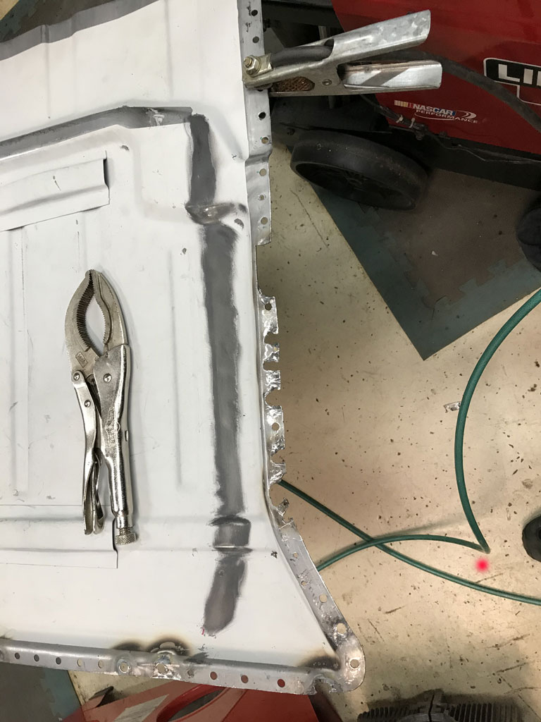
After: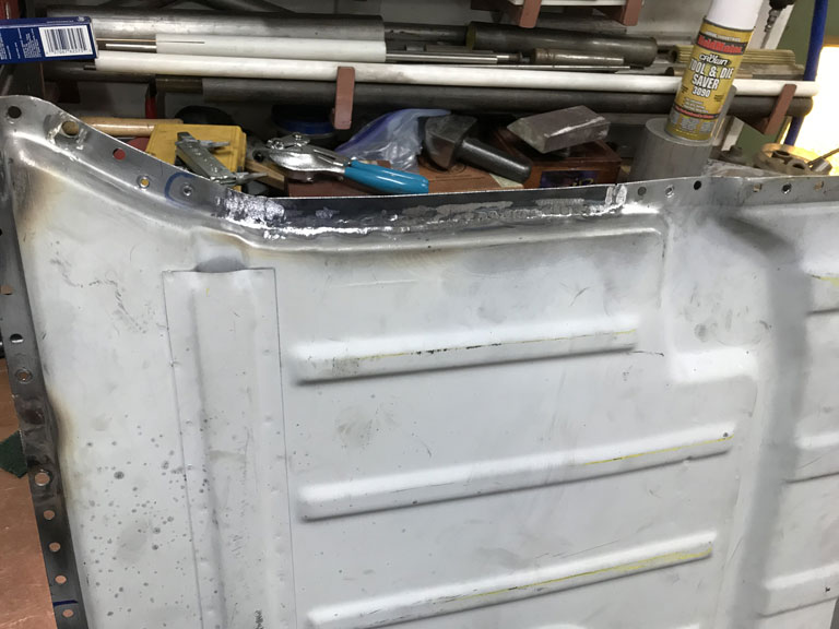
The side flange along the longitudinal was much easier. The holes were intermittently spaced and easily filled just by welding them back up and re-drilling the holes.
Hope to get the driver side pan reinstalled today. Will then wait for the brake tubes and the fuel lines before putting in the passenger side pan.
Posted by: 930cabman Jan 2 2021, 03:11 PM
Looks like you've had your own trials to handle this weekend. How fantastic would it be to have an assembly sequence manual! Can't count the number of times I've had to assembly things twice, or even thrice because I didn't really this thingy-mi-bob needed to go in first. What ever you end up doing, I know it will be done right. Looking good!
BB: the best part of this restoration, what goes first impacts what goes twelfth impacts ..... so goes the madness. As long as we keep moving forward the finish line is out there somewhere. I am sure the factory had the procedure but restoration is a complete new game.
Posted by: Superhawk996 Jan 4 2021, 07:15 AM
Still buttoning up loose ends before the floor pans can go in.
Throttle cable is well supported since it snakes behind a sheet metal doubler inside the tunnel. This was OEM routing.
Here is a quick picture of the fabrication of the throttle cable retention bracket that secures the end of the throttle cable tube. 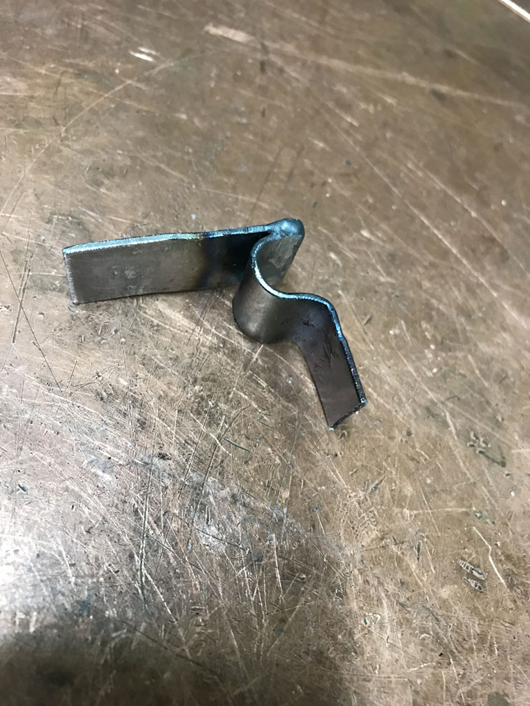
This is the belt and suspenders approch to securing the clutch cable tube. I used two retention bracketes vs. OEM single bracket. I also put a couple dabs of braze between those.
I won't be dealing with a broken clutch tube anytime in my lifetime. 
Posted by: saigon71 Jan 4 2021, 07:49 AM
This is aome amazing work hawk. Nice to see it coming together.
Posted by: bbrock Jan 4 2021, 09:14 AM
I like that tube reinforcement. Wish I had done that. I did add some reinforcement, but nothing as nice as this.
Posted by: Superhawk996 Jan 11 2021, 07:36 AM
OK I'm fully recovered the steps backwards and I'm moving forward again.
Tangerine fuel lines and PMB stainless brake tube were installed into the tunnel while everthing was wide open. 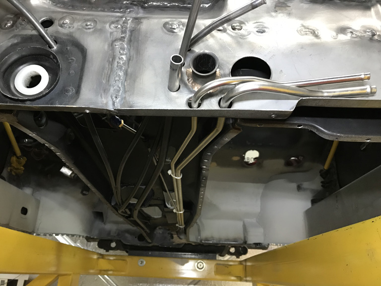
Next up was to put some Eastwood frame coating inside the pedal support bracket. I forgot to do this last time. I had written it off since I had the driver side floorpan tacked in. Well, since it had to come out to get the tunnel tubes installed, now was the time to fix that mistake. 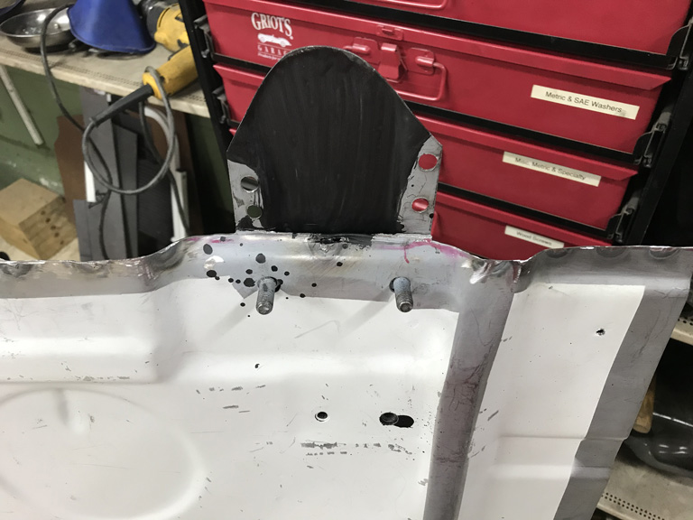
I've finally sprung for a supplied air painting hood. Man what a difference. Nice fresh air, cool breeze blowing in your face. No goggles getting paint misted and fogged. I should have done this years ago. 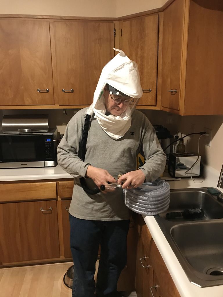
Moved on to primering the passenger side floorpan with 2K and then spent the entire day yesterday fitting the passenger side floorpan. 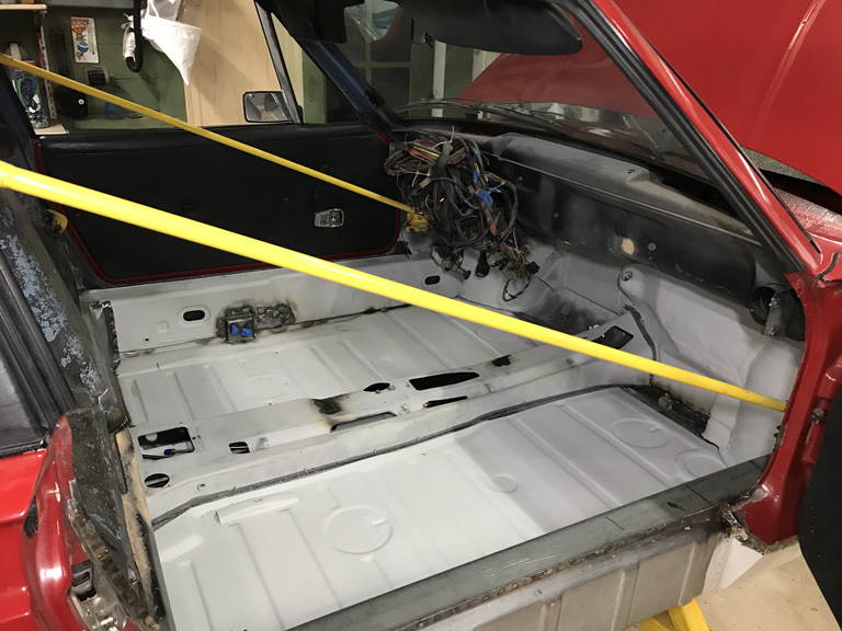
Got my work cut out for me now. Literally more than a hundred and maybe about 200 rosette welds to make to get all this secured. Plus there is a long, long seam down the length of the floor pan that butts the two side together that will take forever!
Posted by: mepstein Jan 11 2021, 08:16 AM
Are the ss fuel lines in for just a trial fit? I would wait on their permanent install until after paint. It only takes 5 minutes with the engine out.
Posted by: 930cabman Jan 11 2021, 08:17 AM
Great progress, where did you find the supplied air hood?
Posted by: bbrock Jan 11 2021, 09:05 AM
Looking great! And yes, I am jealous of that hood.
Posted by: Superhawk996 Jan 11 2021, 12:35 PM
Are the ss fuel lines in for just a trial fit? I would wait on their permanent install until after paint. It only takes 5 minutes with the engine out.
@http://www.914world.com/bbs2/index.php?showuser=10825
No they will stay in. I'm sure it would be straight forward though if the car were up high, and there were only two jackstands involved.
When the chassis is on the build cart it's not quite so simple to manipulate them to get them installed.
I'll just release the lines from the front grommet and pull them back about 5" to paint the fire wall. Obviously, I will quickly tape them though so as not to wreck that shiny stainless steel goodness.
I considered brazing them in to get rid of the grommets and make the chassis a little more water tight. In reality, that is a lost cause due to the shift rod bushing, the park brake cable tubes, etc. They will get grommets once I have some paint on it.
Posted by: Superhawk996 Jan 11 2021, 12:44 PM
Great progress, where did you find the supplied air hood?
@http://www.914world.com/bbs2/index.php?showuser=24877
Amazon. Hobby Air hood from Axis.
Be careful with cartridge respirators and urethane/epoxy (isocyanate paints). You cannot tell when the cartridge is isocynanate saturated. I've always just done small jobs and made sure the cartridges were fresh that day.
Needless to say, there is no cartridge manufacturer that will say their cartridge is acceptable for isocyanate use.
I just got tired of having to worry about it. Should have done this sooner.
Posted by: bbrock Jan 11 2021, 01:00 PM
Be careful with cartridge respirators and urethane/epoxy (isocyanate paints). You cannot tell when the cartridge is isocynanate saturated. I've always just done small jobs and made sure the cartridges were fresh that day.
That's what I've done. I'll use cartridges for basic solvent based stuff as long as I can't smell anything, but before doing anything that uses a catalyst, I open fresh cartridges.
Posted by: 930cabman Jan 11 2021, 01:06 PM
It's a miracle we live through half (or more) of this stuff. Thanks, I will be looking for the hood
Posted by: Superhawk996 Jan 11 2021, 01:27 PM
It's a miracle we live through half (or more) of this stuff. Thanks, I will be looking for the hood
For sure.
I always joke with my woodworking friends that any sissy can make sawdust . . . real men make things from metal.
No disrespect to any woodworkers here. There is certainly an art to wood work too. I just refuse to admit that to my closest friends.
Posted by: bbrock Jan 11 2021, 01:54 PM
It's a miracle we live through half (or more) of this stuff. Thanks, I will be looking for the hood
For sure.
I always joke with my woodworking friends that any sissy can make sawdust . . . real men make things from metal.
No disrespect to any woodworkers here. There is certainly an art to wood work too. I just refuse to admit that to my closest friends.
Disrespect taken! I used to think the same think as a lifelong woodworker. Then I dove into my 914 project. Guess what. Woodworking is harder.
Posted by: Superhawk996 Jan 11 2021, 02:22 PM
Disrespect taken! I used to think the same think as a lifelong woodworker. Then I dove into my 914 project. Guess what. Woodworking is harder.
@http://www.914world.com/bbs2/index.php?showuser=20845
Let me know next time you hold your woodworking dimensions to 0.001" or less. Just remember it's a piece of precision machined steel that is cutting that wood! Just sayin'
Just couldn't resist stiring the pot.

In all seriousness I hold wood working in high regard. When it's done well, it really is an art form. I have an acquaintance that deals in high end cabinetry that costs more than my house is worth. The workmanship is amazing.
Likewise, I've seen some of your woodwork and would hire you in a second when I decide the other house needs cabinets!
Posted by: 930cabman Jan 11 2021, 02:51 PM
Disrespect taken! I used to think the same think as a lifelong woodworker. Then I dove into my 914 project. Guess what. Woodworking is harder.
@http://www.914world.com/bbs2/index.php?showuser=20845
Let me know next time you hold your woodworking dimensions to 0.001" or less. Just remember it's a piece of precision machined steel that is cutting that wood! Just sayin'
Just couldn't resist stiring the pot.
In all seriousness I hold wood working in high regard. When it's done well, it really is an art form. I have an acquaintance that deals in high end cabinetry that costs more than my house is worth. The workmanship is amazing.
Likewise, I've seen some of your woodwork and would hire you in a second when I decide the other house needs cabinets!
We fabricate new custom windows and doors to less than 1/64", generally about .005. have a look at Jagulick.com
I have been lucky to have a solid background in both woods and metals.
All this stuff is very similar, it's all art .... just different materials
Posted by: bbrock Jan 11 2021, 04:21 PM
Disrespect taken! I used to think the same think as a lifelong woodworker. Then I dove into my 914 project. Guess what. Woodworking is harder.
@http://www.914world.com/bbs2/index.php?showuser=20845
Let me know next time you hold your woodworking dimensions to 0.001" or less. Just remember it's a piece of precision machined steel that is cutting that wood! Just sayin'
Just couldn't resist stiring the pot.
In all seriousness I hold wood working in high regard. When it's done well, it really is an art form. I have an acquaintance that deals in high end cabinetry that costs more than my house is worth. The workmanship is amazing.
Likewise, I've seen some of your woodwork and would hire you in a second when I decide the other house needs cabinets!
Let's make this a topic of discussion the next time you pass through my way. Could be fun
Posted by: SavingManuals Feb 8 2021, 10:23 AM
I'm new to the 914 community; so new that I don't yet have a car. Hoping to find a decent one here in Michigan. If you ever want an extra pair of untrained hands, some moral support, and maybe a couple beers, let me know! I'd love to see your project in person and I'd probably learn a bunch to boot. (Yeah, with a mask for covid). I'm about a 1/2 hr north of Troy. Regardless, looks like you're doing some magic there!
Posted by: Superhawk996 Feb 15 2021, 07:33 AM
I hate February
February is the month that never ends . . . even though it's only 28 days long.
The temperatures really drop, the snow piles up, the ice dams form on my garage roof from heating it. In order to keep the ice dams under control, I have to rake the snow off the roof. Yup, for you CA guys, roof rakes are a real thing.
The good news of February is that I now have the floor pan and tunnel completely welded in. That let me move on to getting the seat cross members positioned for welding and I was also able to mock up the seat tracks and tack in the seat hinges. 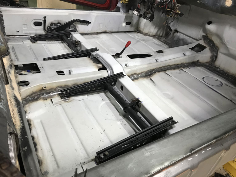
Oh, and then there are those time consuming details that you tend to forget about like locating the parking brake switch that needs to occur after you've already positioned the driver side seat cross member. 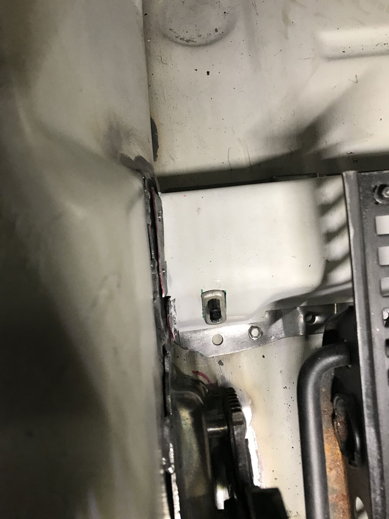
If anyone is interested, I have some donor sheetmetal for the tunnel section that needs to either go to a new home or the trash. I'll post one more time later on in classifieds. 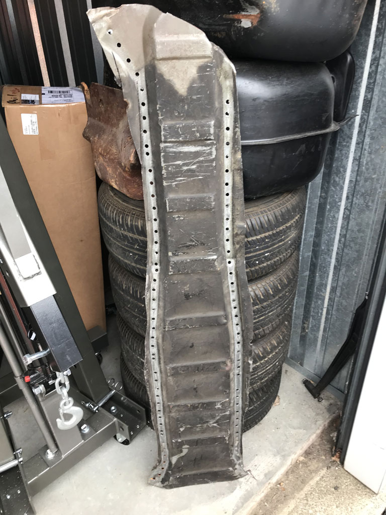
I also have the front tip of a tunnel that connects to the front firewall where the clutch cable and throttle cable exit. Both are unused leftovers from donor sheetmetal.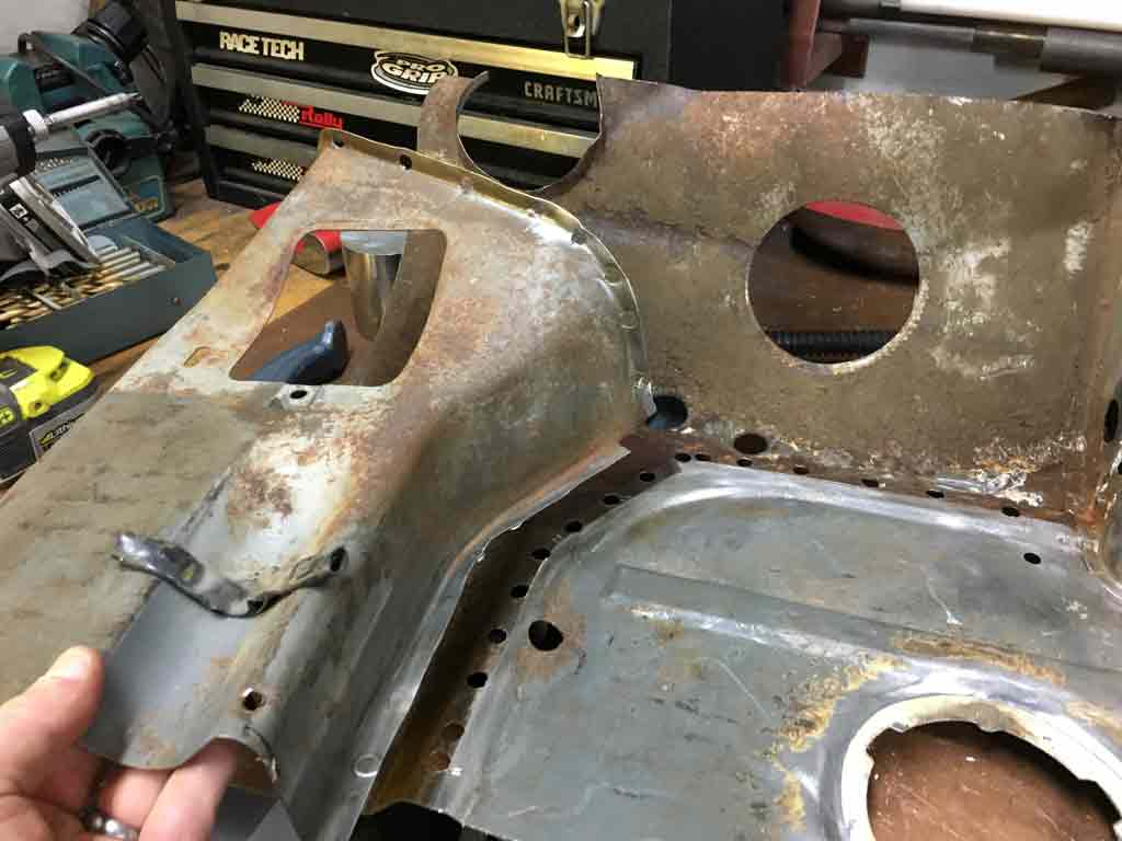
Posted by: bbrock Feb 15 2021, 08:23 PM
Looking good! Somebody is going to want that front tunnel section. I had to do a lot of fabrication up there. That little piece would have saved a lot of time.
Posted by: 930cabman Feb 23 2021, 03:09 PM
Looking good! Somebody is going to want that front tunnel section. I had to do a lot of fabrication up there. That little piece would have saved a lot of time.
Funny how that works, if I knew then what I know now ....
Posted by: Superhawk996 Feb 25 2021, 06:49 PM
Gratuitous Parts Porn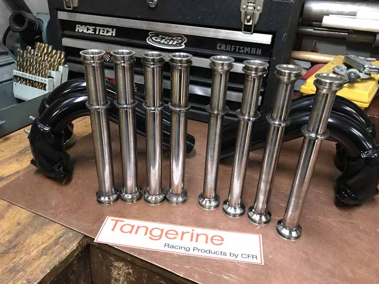
Parts being collected for /4 engine that will hopefully power this chassis down the road this fall. /6 conversion will occur the following winter with a little luck.
Inspected & compared to OEM. 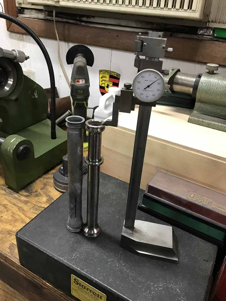
Can't wait to put these to use. Necessary - nope. But come on, these are an example of beautiful hand fabricated parts that will make you want to set valve clearances just so you can spend some time looking at the bottom of the engine.
Happy to have the opportunity to support our vendor community!
Posted by: mb911 Feb 25 2021, 06:52 PM
I know something else that will be boxed up and heading your way. The very last of my original design. Boxing tomorrow afternoon.
Posted by: Superhawk996 Feb 25 2021, 06:53 PM
I know something else that will be boxed up and heading your way. The very last of my original design. Boxing tomorrow afternoon.
That will make me the the proud owner of your 1st 2.0L muffler that will go with this /4 and the last of your original design pipes for the /6. Can't wait to see those! I think they need an autograph!
You guys make the rustoration slog bearable. Gotta keep the dream alive - so easy to get lost in the endless puddle welds.
Posted by: bbrock Feb 25 2021, 06:54 PM
Can't wait to put these to use. Necessary - nope. But come on, these are an example of beautiful hand fabricated parts that will make you want to set valve clearances just so you can spend some time looking at the bottom of the engine.
Happy to have the opportunity to support our vendor community!
I'm going to remember this the next time you poke fun at my OCD
They are purty though.
Posted by: Superhawk996 Feb 25 2021, 07:00 PM
I'm going to remember this the next time you poke fun at my OCD
They are purty though.
Yeah, I knew I had that coming.
Posted by: Superhawk996 Feb 28 2021, 06:46 PM
Details are a PITA
It takes way longer to button up the little detals than you think it should. Getting floor pan and the seat cross members installed was a major milestone. But, all the details are killing me.
Spent the whole afternoon on the following stuff:
1) Weld in @http://www.914world.com/bbs2/index.php?showuser=1319 's seat comb brackets. These in themselves were a huge timesaver. If I had to make them from scratch that would have taken a couple extra hours. That was about $35 bucks or so that was well spent!
2) After more trial fitting of the seat tracks, I was able to final weld the RD seat hinges to the floor pan
3) Weld in the RD bracket that goes over the parking brake equalizer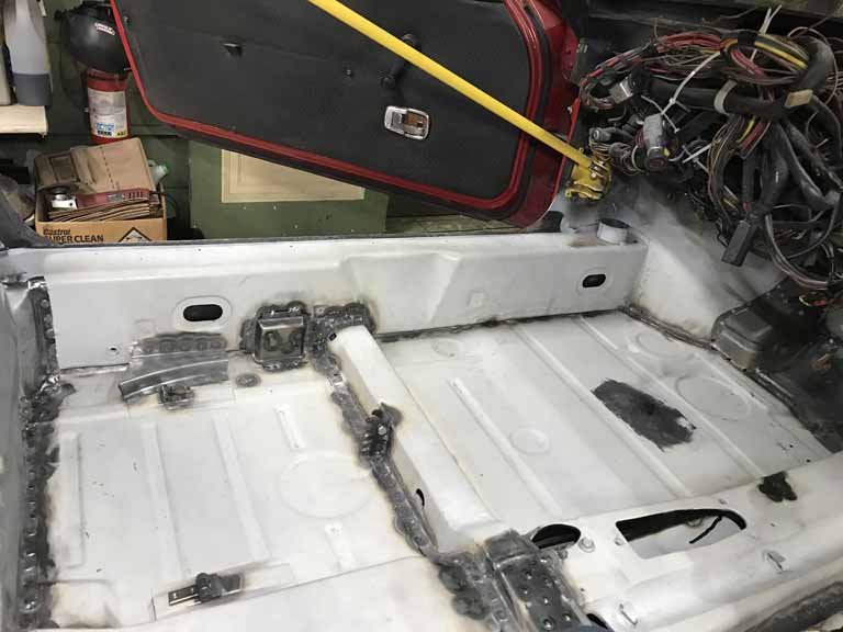
4) Used the shrinking wheel to remove some oil canning from the front of the driver side floor pan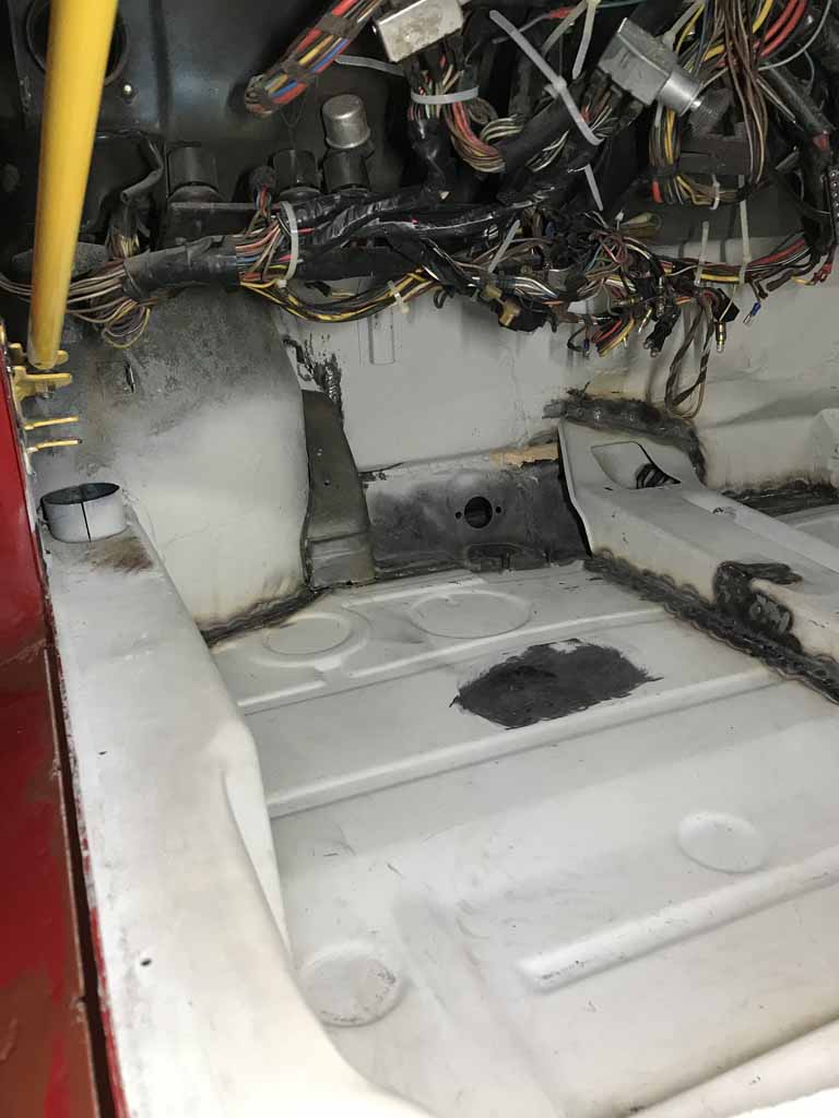
5) Trial fitting and mock up of the wheel house reinforcement that supports the plywood pedal board. This is the LAST job I need to do down in the dreaded pedal box area that aggravates me so much! 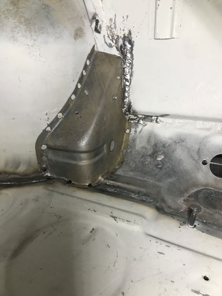
And I didn't even get around to fabrication of the little trim tab that holds the return spring that goes to the park brake equalizer.
The good news: Tomorrow is March. Fuch February! Good riddance! Days generally only get warmer from here on out. Was 46F today
Posted by: bkrantz Feb 28 2021, 09:31 PM
Yeah, the devil (or something nasty) is in the details. But the way you solve the details will prove the ultimate quality of the results. Keep up the good work!
Posted by: bdstone914 Feb 28 2021, 10:40 PM
I have one more pair of the seat adjuster combs. I sold the remainder to Restoration Designs as there cross members dont have them.
Posted by: bdstone914 Feb 28 2021, 10:47 PM
And I didn't even get around to fabrication of the little trim tab that holds the return spring that goes to the park brake equalizer.
Actually that tab has to hole for the cover plate plate. The spring hooks into a loop on the fire wall.
@http://www.914world.com/bbs2/index.php?showuser=22428
Posted by: Superhawk996 Mar 1 2021, 07:11 AM
And I didn't even get around to fabrication of the little trim tab that holds the return spring that goes to the park brake equalizer.
Actually that tab has to hole for the cover plate plate. The spring hooks into a loop on the fire wall.
@http://www.914world.com/bbs2/index.php?showuser=22428
@http://www.914world.com/bbs2/index.php?showuser=1319
Oh
I forgot about that extra cover plate. My car came to me without one.
Do you have any for sale? Obviously I could fab one up from scratch but this fall in the category that I'd much rather have OEM metal vs. a hokey homebrew fabrication.
Posted by: 930cabman Mar 1 2021, 07:15 AM
I'm a step behind you Hawk, just starting to get the floors in. It's either right or it's wrong.
Posted by: Archie Mar 2 2021, 07:35 PM
Gratuitous Parts Porn
Parts being collected for /4 engine that will hopefully power this chassis down the road this fall. /6 conversion will occur the following winter with a little luck.
Inspected & compared to OEM.
Can't wait to put these to use. Necessary - nope. But come on, these are an example of beautiful hand fabricated parts that will make you want to set valve clearances just so you can spend some time looking at the bottom of the engine.
Happy to have the opportunity to support our vendor community!
Nice. Very nice!
Posted by: Superhawk996 Mar 3 2021, 06:26 PM
Rut Roh, I think I'm developing a parts porn addiction.
I hope the wife doesn't find out. 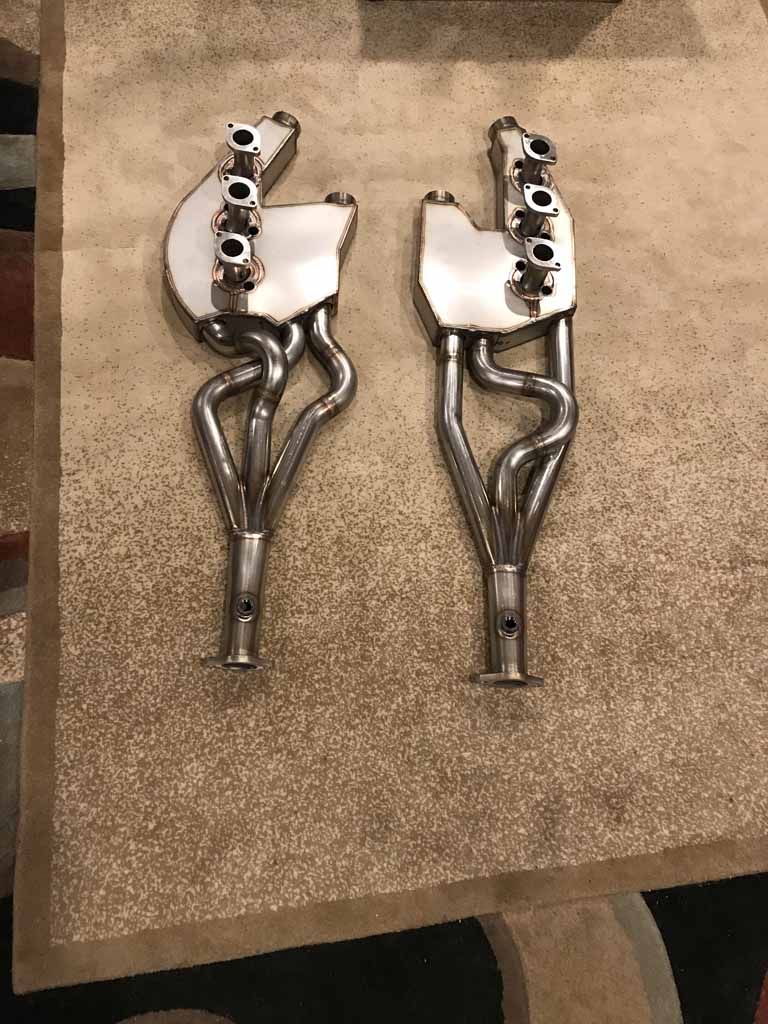
@http://www.914world.com/bbs2/index.php?showuser=9892 - parts recieved in perfect condition. Thanks for making these available to the community!
Posted by: Morph914 Mar 3 2021, 06:31 PM
Oh my! Those are parts porn for sure.
Posted by: Superhawk996 Mar 8 2021, 07:36 AM
Output from this weekend wasn't very impressive. Somebody stole Saturday. Not sure where it went.
I retrieved the pedal board from storage only to discover that it is missing the clutch pedal stop hardware. Sort of amazes me that I took some of this stuff apart so qucikly I didn't notice little details like this that were missing as received. I'll have to post a WTB over in classified and see if someone has a spare. 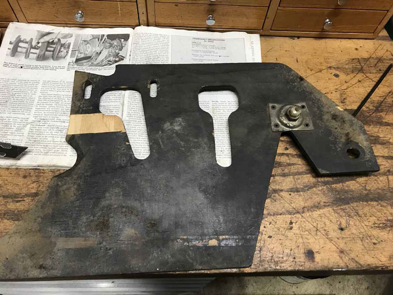
I spent most of Sunday with my body contorted into uncomfortable positions. Having installed the seat cross members and seat comb brackets there are new protrusions in the cabin to deal with and brusing to prove it.
Got this bugger welded in with a bunch of puddle welds to tie it back into the original sub that was still rock solid.
Flooded the inside with Eastwood Frame coating once it was welded in which is why it's so black around the edges. 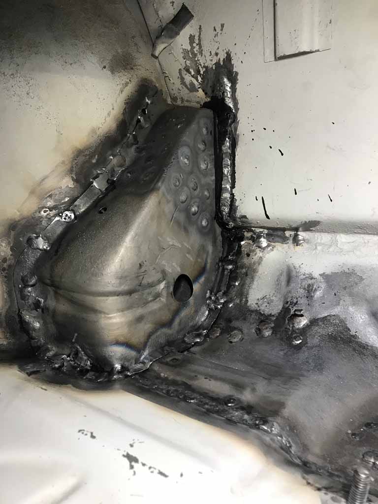
I truly hope this is my last extended excursion down into the pedal box area for welding purposes.
Still have some easy work to do like doing the seam sealer, etc. Also need to clean up the entire floorpan and get a fresh coat of 2K primer on it to cover all the new welds for crossmembers, tunnel, etc. That shouldn't be nearly as painful.
Posted by: Superhawk996 Mar 14 2021, 01:58 PM
Color By Numbers
I've been using Spray Max rattle can 2K primer all along with great results. Good adhesion, and super easy to use. Small quantity in the can is perfect for small panel sections. Most importantly, no gun clean up.
This weekend was a little science experiment. Previous owner told me car was repainted in BMW Color Code 138 - Cinnabar.
So I ordered up some Spray Max 2K single stage color from a paint supplier out in Spokane WA. About $33/can inclusive of shipping. Ordered 3 cans.
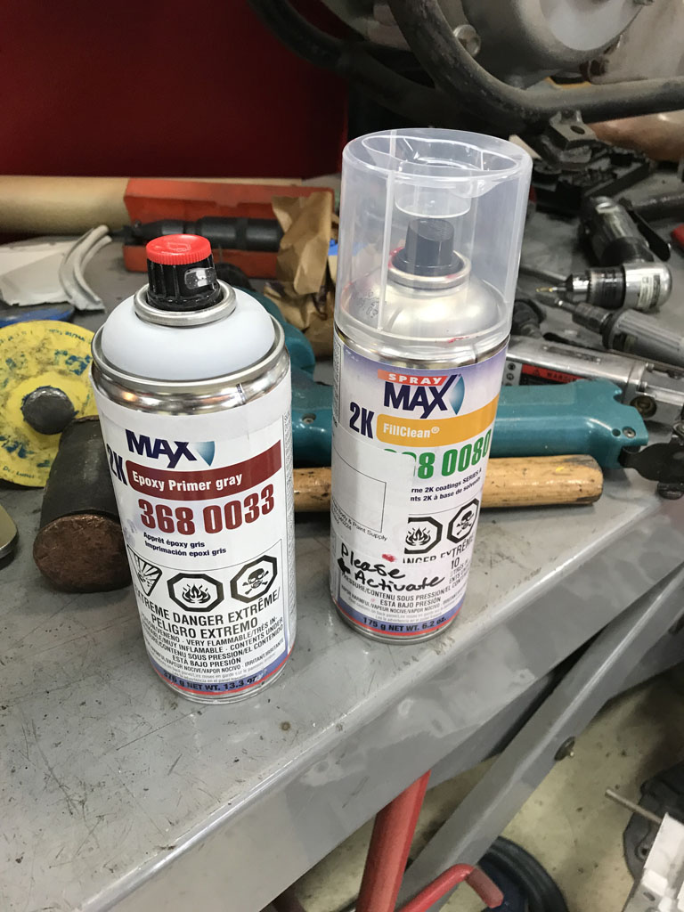
Since I know this car will eventually completely stripped and taken back to OEM color (Alaska Blue Metallic) way off in the future, I'm not terribly concerened about the passenger compartment or engine compartment finish quality.
So I figured, let's see how a rattle can catalyzed color works! 
So last night, I cleaned off any of the primer from weld areas that was heat affected, and did a quick wipe down with PPG degreaser and went to town with a fresh coat of primer to cover all the puddle welds and dusted the rest of the panels. 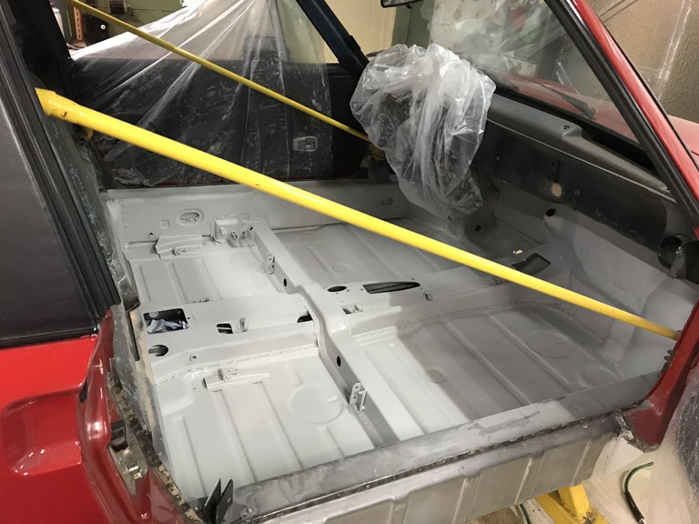
Now on to the fun this morning. Spray Max data sheet says for the 2k primer says "Can be topcoated with all conventional 1K and 2K paints. If the 2K epoxy primer-filler is topcoated after more than 1 day, it must be sanded first. "
I took this and ran with it in a way I wouldn't for an exterior panel. I decided I just give it a quick wipe down with a tack cloth and shoot the color -- no sanding. Don't start with me - I'd never do this for a top quality job.
Well, all said. I'm pretty happy with how this turned out. Maybe only slightly worse than Maaco. 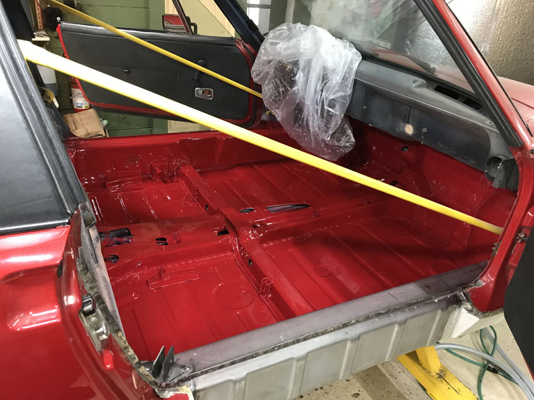
This 1/2 quality is not something I'd normally celebrate, but, not bad for a rattle can job. There is some dust in it (surely didn't clean the garage) and a couple random fisheyes. Not completly surprised by the fisheyes since I didn't do any sanding nor did I hit it again with PPG degreaser before I spayed the rattle can color. When it's all said and done, most of this gets covered by Dynamat and then carpet so I'm OK with it as a science project. It will all get stripped out again someday.
Next up was to see how the color matches. I took the opportunity to just shoot a little primer and color over my previous Fuch up to the rear quarter. Again, this is just a science project. I didn't fill the bondo hole. I didn't feather the paint. And, most obviously, I made no effort to blend the paint area. I wanted the sharp contrast line from masking.
I just wanted to get an idea of how close the rattle can paint is to the exterior panel color that could be sun faded to some extent.
I'm torn between trying to just do a quick spot repair on this to put it on the road this fall or to send it out for a professional touch up.
I'm not great at color matching. I'm an engineer after all. I can barely tell blue from green and my wife is convinced there is some color called Teal between the two.
To my eye, this was pretty darn close. It's off a little bit, but, it might be OK until I get back to OEM color. 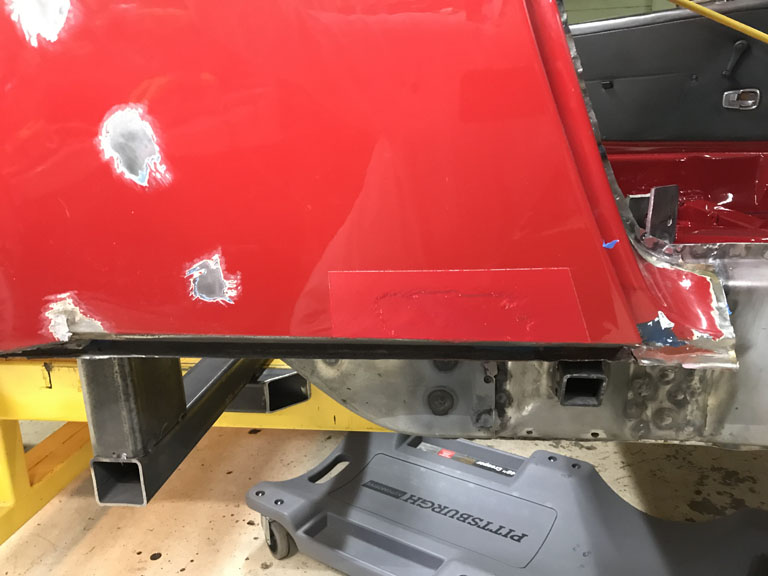
I'm thinking with actual time to do the spot repairs properly, and, with the use of a little Spray Max Spot Blend it will be good enough to drive it this fall. I don't like the idea of paying for a professional blend becuase those are never perfect either and ultimately the whole car needs to be stripped and returned to Alaska Blue. Sort of seems like a waste of time (at paint shop) and money. For a Pro shop to do it right, it will have to be blended out into the door and up into the trunk. That's just seems silly for a color I dislike anyway.
Posted by: Superhawk996 Apr 11 2021, 06:16 PM
Stupid 50 year old parts
Didn't have a lot of time this weekend to do big projects so I tried to get parts cleaned up and ready for some distant time in the future when this car might get put together again.
Wanted to get a variety of parts ready to go to powder coat but 50 year old abused parts had another plan.
First up was cleaning weld spatter from the rear trailing arms. Easy enough.
In the process I discovered that one of the trailing arms has a hole in the thru-tube that allows access to the rear caliper adjustment. I can't figure out how this happened. Measuring parts doesn't seem like I'm dealing with a tweaked trailing arm. I'm thinking some one tried to put a hook in there and tie it down and the hook pierced the thinwall tube?
I have a fix planned to insert a 1" OD .065" wall tube into this one and then weld it in place. Awaiting tube. A little more measuring too before I do the repair. 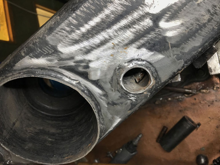
So I retrieved my engine cross bar to get that cleaned up a little. Well turns out that someone must have run it quite a while with a loose bolt. Somehow the through hole is oblong. 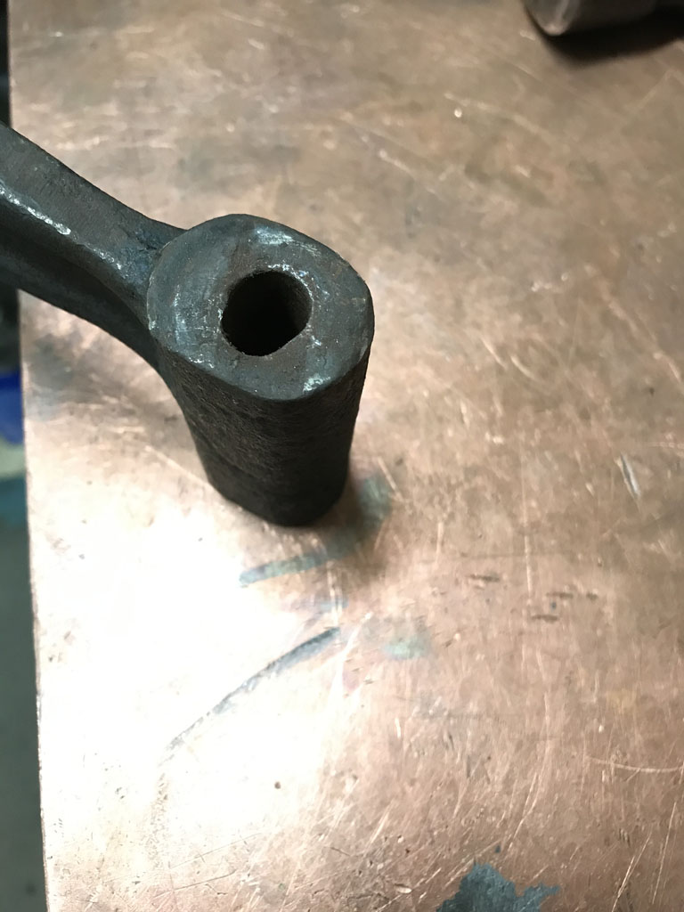
I've got a fix planned. But 1st I thought I had an easier solution. When I bought engine GA000099 it came with a engine bar. But of course it had some damage too.
Weird thing was it had a bolt sheared off and rusted into it. 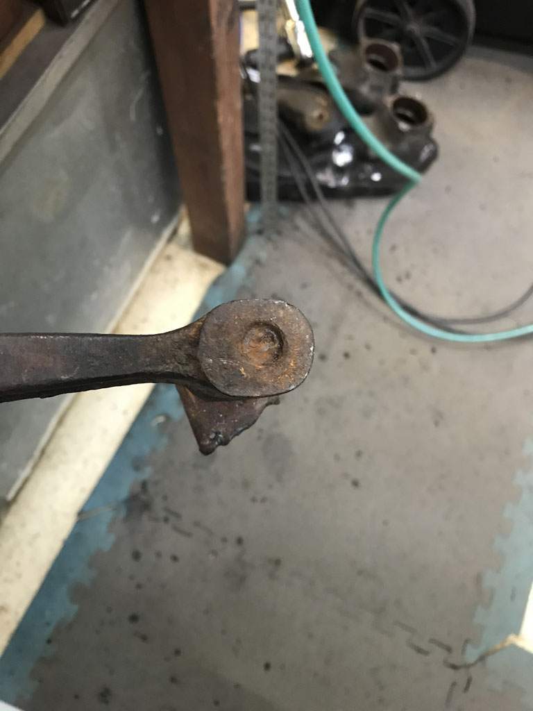
And the top looked like someone might have plasma cut the upper U shaped bracket to free it from the car since the bottom had clearly sheared off. 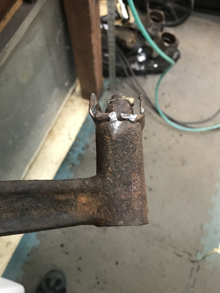
Sort of weird but I figured it would be easy enough to mill out the rusted bolt. Set it up in the mill. Only then did I notice the whole damn bar is bent! 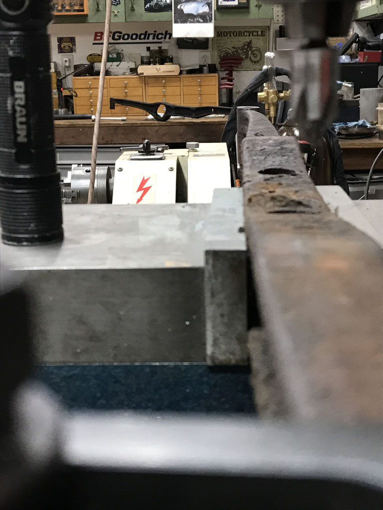
Ugh!
Well, I guess I'll revert back to fixing the engine bar that came with my car! Will machine up a plug to fill the oblong hole, will weld it in, and then rebore the through hole.
Good weeknight project. Maybe by then my 1" OD tube will show up and I can fix the trailing arm.
Some days . . .
Posted by: bbrock Apr 11 2021, 08:41 PM
My engine bar had a bolt rust welded into the bar and sheared off just like that. MAPP gas and a BFH took care of it. I'm pretty sure you could bend that straight too. I had to straighten one once and recall it being pretty easy to clamp in a vice and straighten it out.
I can't imaging that wallowed out hole will be an issue once the bolts are torqued down, but I like the sleeve idea.
Somehow I missed your March update with the rattle can 2K. That's pretty cool!
Posted by: Superhawk996 Apr 18 2021, 11:36 AM
Problem Fixes:
Trailing arm was fixed by inserting a piece of 1" OD, 0.065" wall tube into the orignal though tube and then welding it up slowly. This will keep water and excess garbage from being funneled into the trailing arm. 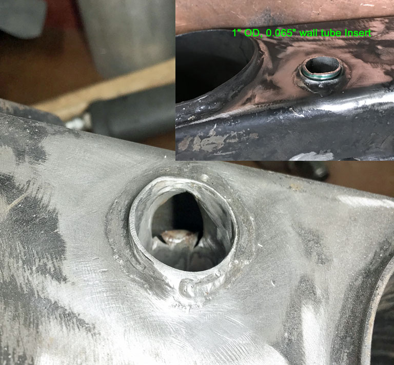
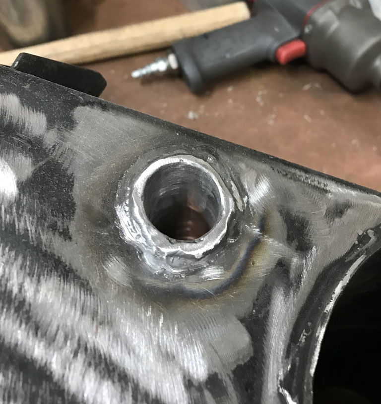
Engine bar was fixed by turning up an insert to fit the hole that was elongated and then welding it in place. 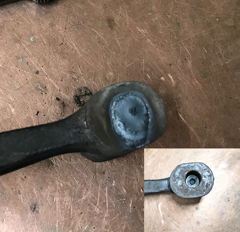
Excess weld was flycut back to original surface. Re-drilled the though hole. 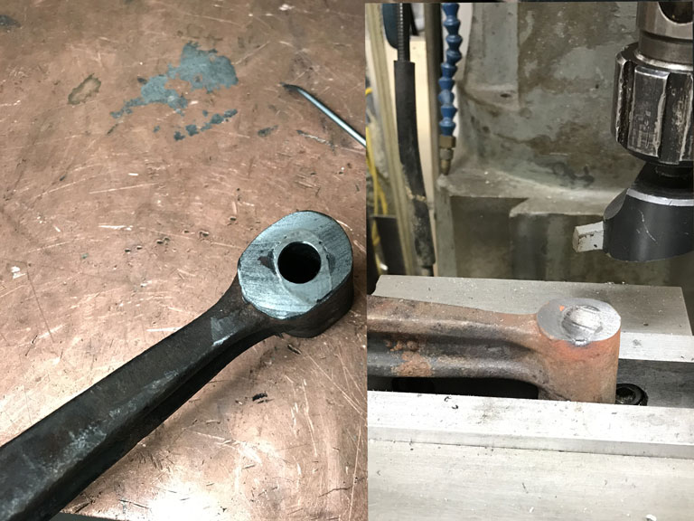
Fixed right and good for another 50 years. On to bigger and better things
Posted by: 930cabman Apr 18 2021, 12:57 PM
@Superhawk, when does it end??
Posted by: Superhawk996 Apr 18 2021, 01:57 PM
@Superhawk, when does it end??
@http://www.914world.com/bbs2/index.php?showuser=24877
End?
It never ends Finish chassis structural rustoration to get to a driveable state.
Many more bits still need powder coat and/or plating
Assemble the stock 2.0L four cylinder engine with hope of driving it a smidge this fall
Rebuild transmission for long term reliability.
Finish rebuild of 2.4L six and associated conversion bits and do conversion.
Eventually do full rotisserie re-paint and steel flares
1000 other little tasks (fix wiring, add the front fog lamps that are missing, replace all rubber seals)
And notice I haven't even included the other curve balls life always throws at us.
Posted by: 930cabman Apr 18 2021, 04:55 PM
True, it ends when we are carried by six, then our kids can figure it out. Lucky them
Posted by: Superhawk996 Apr 26 2021, 06:08 AM
Spent some time this weekend filling in the hole left when the passenger side bulkhead had to be cut to rebuild the long all the way back to the trunk.
Upper portion of the hole was easy. I just reused the section cut out and that was done months ago.
The lower portion that constitutes the hell hole was a bit more fabrication work. Not a big deal but time to create templates and need to fix a small section of pinholes down at the engine shelf slowed it down.
Wanted to recreate the same type of weld flange as was there originally.
Couple views of the templates. 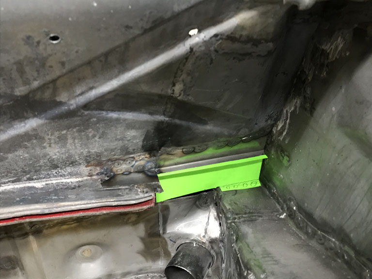
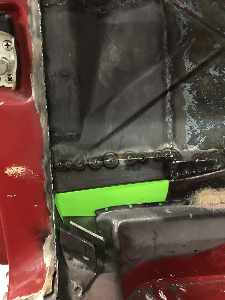
Metal in place 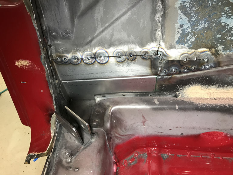
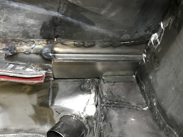
Unfortunately, I ran low on Argon and could only tack weld in parts this weekend. Poor planning on my part.
Posted by: Superhawk996 May 9 2021, 06:41 PM
No big progress of late. Lots of little jobs.
Finished up close out of the rear passenger side bulkhead and started some rough fit up of the inner suspension console. 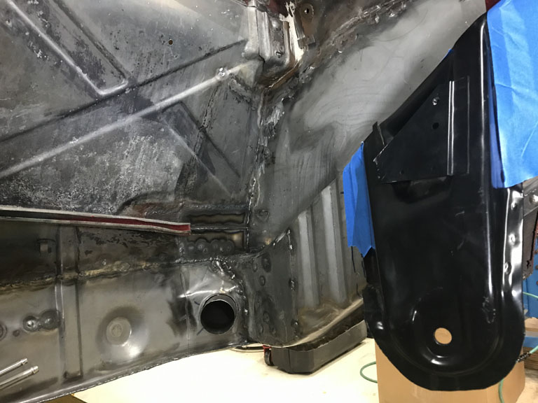
Filled another one of the holes in the passenger wheel house that was hacked for the AC install. Still needs some finish work. And of course there were also a couple of other P-clip holes where the metal surgeons just shot self tapping screws though the wheel house. 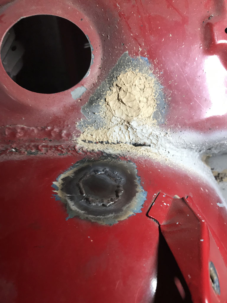
While I was screwing around up in that area I decided to do a little VIN excavation. The heavy primer and paint over it rendered it barely readable. 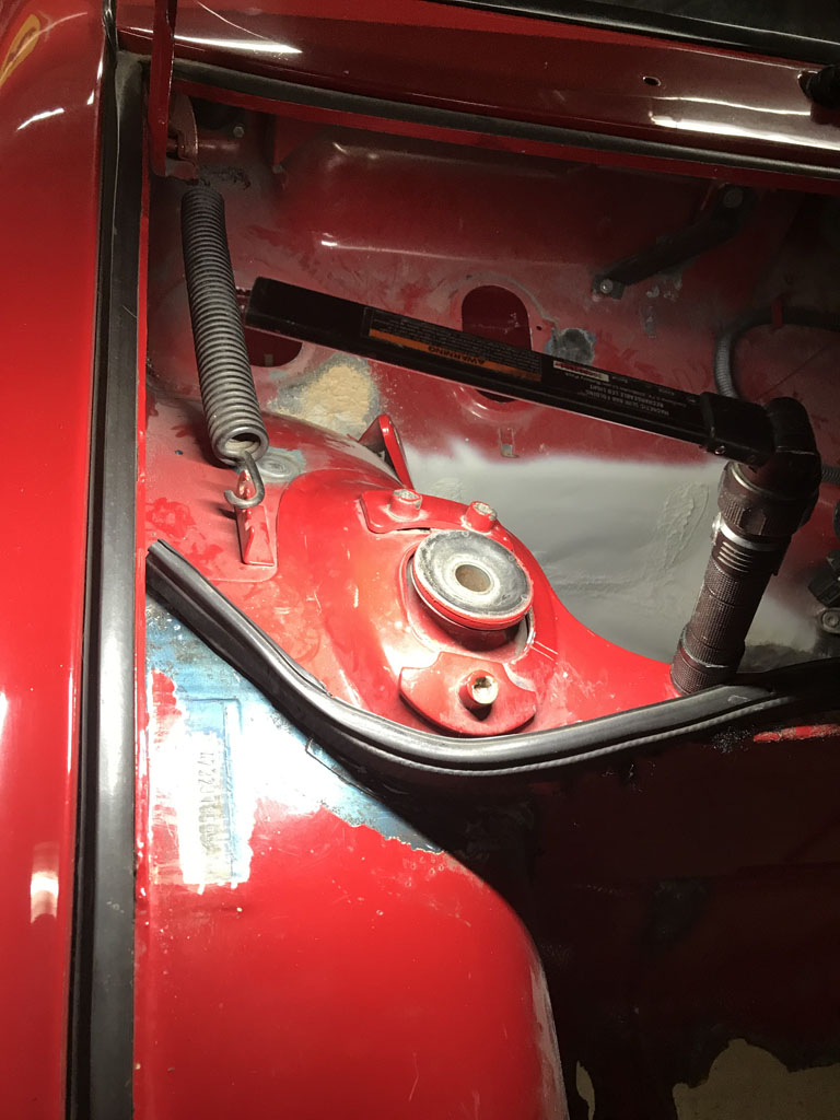
And in anticipation of having to do final fitting of the suspension console, I figured I better do another round of measurement since I hadn't done one since installing the floor pans, tunnel, and seat crossmembers.
I couldn't be happer than a pig in . I was able to get the last little bit of "match boxing" of the chassis out with a diagonal heim joint brace that went from rear of passenger door to the front driver cowl area. 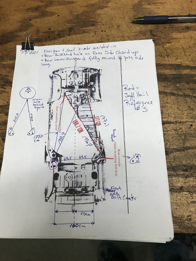
Posted by: 930cabman May 10 2021, 04:50 AM
Small bites are the only way we can complete these projects. Keep up the good work and thanks for documenting, I will be following soon with our rustout project, but on to the "rust free" project for now.
Measure twice, weld once should be our mantra
Posted by: Superhawk996 May 15 2021, 10:10 AM
Wanted to just drop a quick post to thank Pete at Restoration Design.
I couldn't find a local Detroit supplier that was willing to sell me some shear cuts of 18 gauge Galvaneal. My usual suspects don't stock Galvaneal, and/or weren't willing to sell just a partial sheet.
I only needed enough to "wrap" the corrugated longitudinal section up in the engine compartment. I want a smooth OEM look. And to top it off the location where my inner suspension console needs to sit is partially, overlapping one of the corrugations. It need to be built out a bit for stiffness and then I'll wrap this into two layers like OEM section was. I'll also have enough to fix the rust pin hole section of the rear bulkhead behind the driver that was damaged by the OEM noise insulation that holds water. 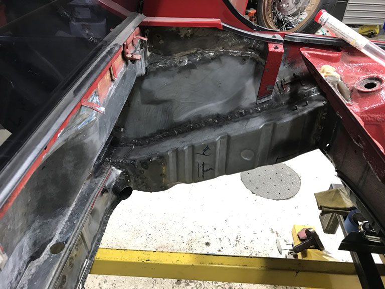
Why do I want Galvaneal so much? Short answer is that it has a thin layer of zinc annealed into the surface layer of the steel itself. It does a great job of holding off corrosion. Note that the bare metal shown above is over two years old, welded, and not showing any signs of surface rust that untreated sheet metal would. That is especially important to me where I'll end up with two layers of steel. The gap between two layers is a great place for corrosion to get started. I trust Galvaneal more than weldable primer.
So not finding what I wanted locally, a quick PM to @http://www.914world.com/bbs2/index.php?showuser=8858 landed me with exactly what I wanted at a very nominal cost. 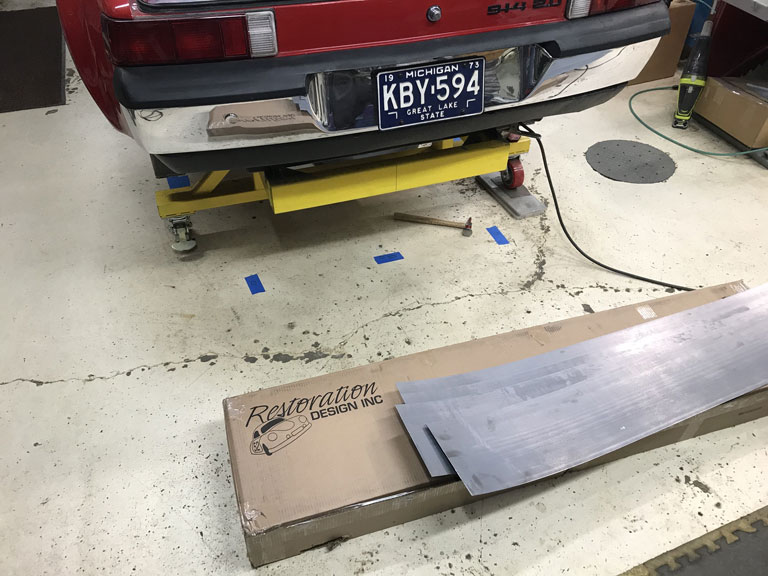
Awesome company & great people supporting our vintage Porsche's. Support them whenever you can!
Posted by: bbrock May 15 2021, 12:14 PM
Good idea using Galvaneal on sandwiched parts. Now I wish I had done that. I like the way it welds too even though I know that zinc is a bit nasty. I'm also not sold on weld-thru primer. After noticing that even the UPOL good stuff has about the same burn back as 2K epoxy and not being able to find a single hard datum that it actually protected the metal or prevented rust better than other primers , I decided to stop draining my wallet to resupply on weld-thru.
I don't mean to brag but two year old welded metal in my shop looks just your galvaneal even without the zinc. On second thought no. I DID mean to brag. As a Midwestern escapee, that's exactly what I intended to do.
Posted by: peteyd May 17 2021, 10:55 AM
@http://www.914world.com/bbs2/index.php?showuser=22428
I'm glad I could help out and get it to you before the weekend.
We want to eliminate this process for the customer in the future, so we will be making the two pieces combined. Once we get back to making tooling for the 914 that is.
Pete
Posted by: Superhawk996 May 29 2021, 09:46 AM
Parts Porn
Suspension parts back from powder coat this morning. @http://www.914world.com/bbs2/index.php?showuser=1319 provided a nice set of plated pivot shafts. 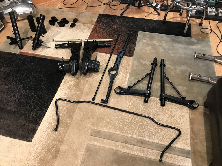
Will be a while before all this ends up back on the car. Memorial Day weekend, so hoping to get some time to get templates created for the engine bay long, and maybe get some of the welds under the floor pan cleaned up, seam sealed and painted. Might be ambitious.
Posted by: Superhawk996 Jun 1 2021, 06:27 AM
All in all, got some stuff done despite other comittments.
Got a template made. Will make this in 3 pieces. Top bottom and sides to accomidate ease of fabrication and to take care of the compound curvatures. 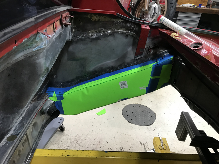
Underbody got seam sealed first, and then shot on some 2K epoxy primer. Still need to shoot some primer over the sealer once that dries. Undecided on how to proceed with all the puddle welds. Seam sealer seems like overkill since they aren't likey to wick in water. I'm thinking Raptor or other underbody coating will likely seal them and make them a little less obvious. Still time to decide on that. 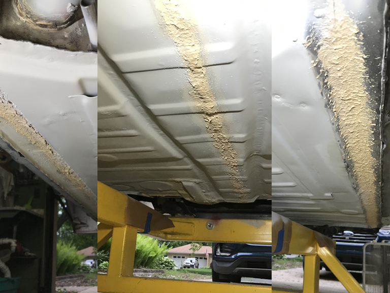
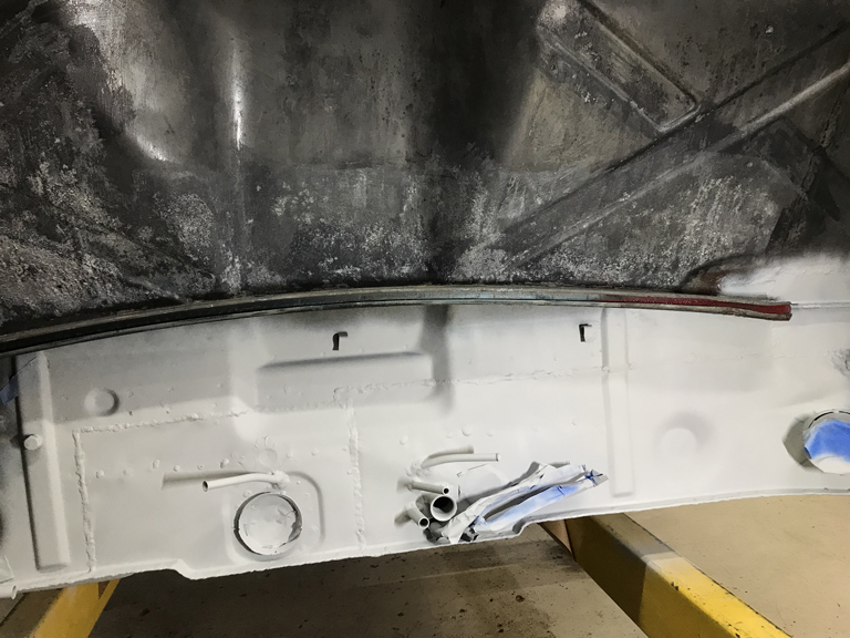
And I managed to get in a little bonus project. Bumper chrome was getting a bit nasty after 3 seasons of sitting around so a little maintenace polish was in order. The fact that this car was largely complete and had great bumpers was 1/2 the reason I bought it in the first place. 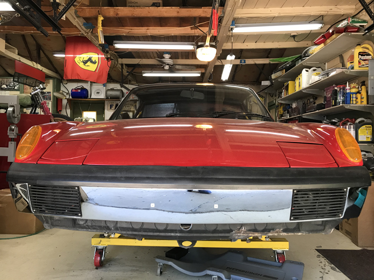
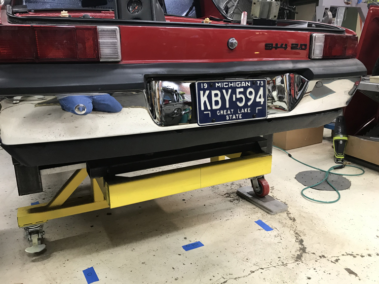
Posted by: Superhawk996 Jun 5 2021, 03:03 PM
You know you're getting too old when installing trailing arm bushings and a pivot shaft is enough work for one day.
Used @http://www.914world.com/bbs2/index.php?showuser=1319 's install tool to get the job done. I really would like to do this with a shop press, but I don't really have room for one. Somehow I've made do without one all my life but this job is testing me.
Nothing wrong with Bruce's tool. Just a lot of high effort wrench turning. Wouldn't even have affected me 20 years ago! In fact, it really is a pretty great tool that helps keep the bushings from being sucked into or pushed out of the the arm.
I bought the Restoration Design bushings that Bruce did a group buy on a while back. Apparently it comes with complimentary loaner of the installation too.
I decided on a belt and suspenders approach so I glued my bushings into the trailing arms using grip glue before starting the install. Loved the instruction label that came with the glue. 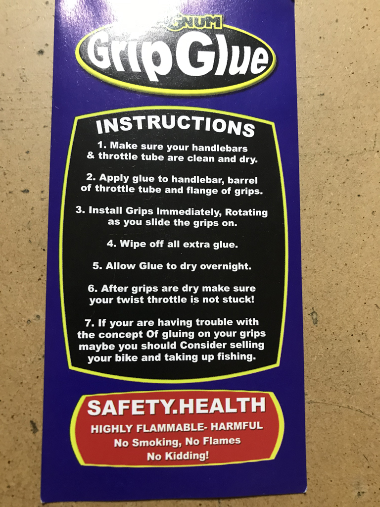
Tool setup is straight forward, using a threaded rod to pull the pivot shaft into the bushings. 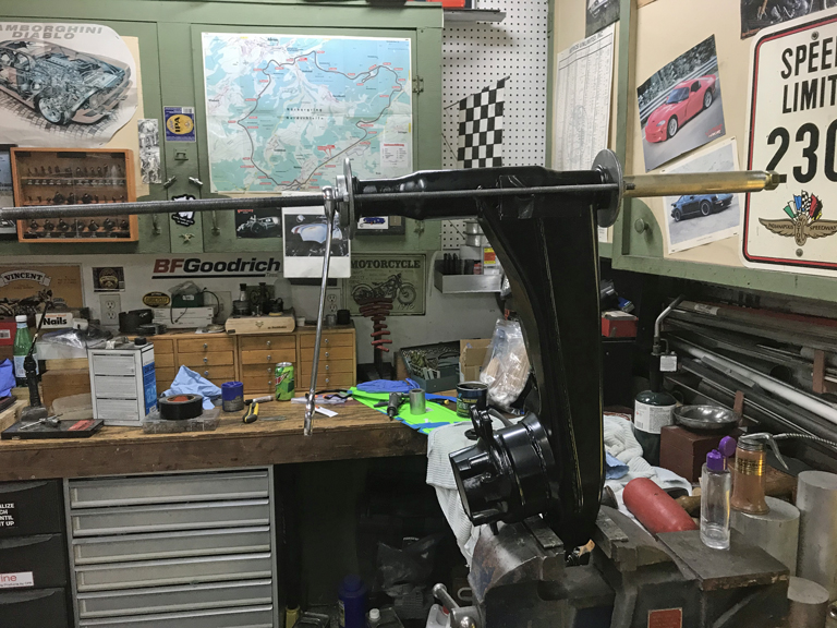
Lots of wrench turning later, done! 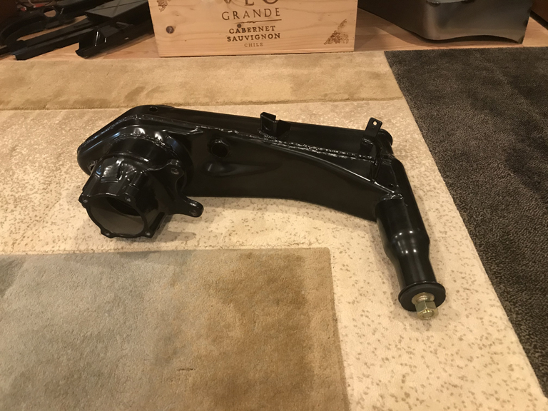
2nd one on deck for tomorrow!
Many thanks to Bruce for doing the group buy of RD bushings, for creating the install tool, and of course for the use of the tool!
Posted by: Superhawk996 Dec 6 2021, 10:20 AM
Been a long time since I've posted in June. Lots of life getting in the way of progress on the 914.
Trailing arm bushings were sucessfully replaced with RD 85 duro bushings.
During the install on the 2nd arm, I managed to put a tear into one of the bushings. Problem was, I only had 4 bushings.
To make a long story short, after trying to source them directly out of RD Europe, after multiple e-mails back and forth trying to make sure I got 85 duro parts rather than the softer OEM parts, Alex at RD Canada got involved and came though! Can't say enough good things about Restoration Design.
But by that time I was out west though the end of August and nowhere near the 914. By Sept, it became clear that my job and my wife's job are in jeopardy. Nothing like the possibility of the full loss of 100% of the household income to put a damper on things. Priorities immediately shifted. Sept/October were spent getting Michigan house ready to go up for sale.
Now there is a high priority on getting this thing back to a rolling chassis in preparation for a move. So close but yet so much to do to make that a reality. I think I have between now and spring to get it done.
Dug out the Caswell plating kit, knocked out the trailing arm bearing retainers to top off the new wheel bearings that had been pressed in. Did a bunch of other parts like the Front ARB lever arms, drop links,etc., while I was at it.
A couple quick pictures.
Retainers before plating: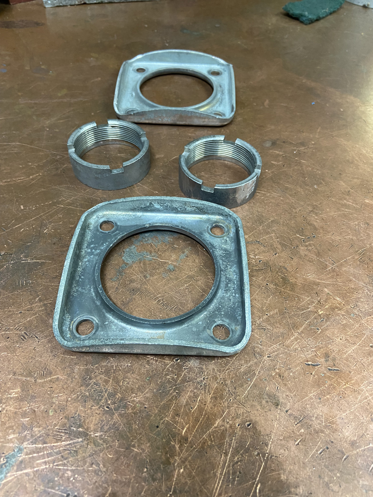
After - installed onto trailing arms: 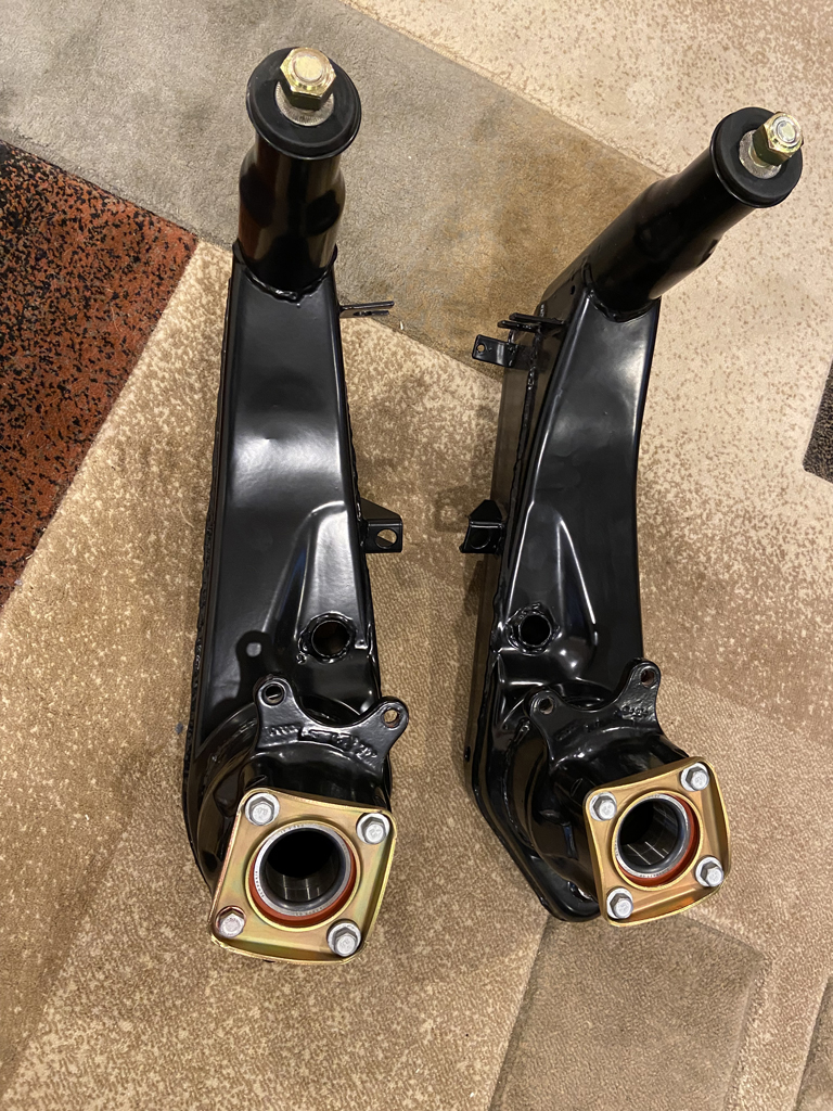
Next up - get the 5 lug hubs cleaned up and pressed.
Posted by: 930cabman Dec 6 2021, 01:45 PM
Lookin good, and yes, life can get the way big time. It took many years for our 914's to get in the condition they are(were) and will take a bit of time to get them right again.
Also, the boys at RD know how to rock it out. I can't say enough about them
Posted by: TRS63 Dec 7 2021, 02:05 AM
I finally took the time to read your thread from start to finish..amazing work here and a lot of very helpful details/pictures, thanks a lot!
Also loving to see another one TIG welding!
Cheers
Antoine
Posted by: 914_7T3 Dec 7 2021, 11:09 AM
Phil,
Your suspension components look great!
Not ideal to have so many things coming at you at the same time, hope you can get her rolling in time for the move!
Posted by: Superhawk996 Dec 9 2021, 05:44 PM
Cranked out a few more plated parts. Had intended to ship these out for professional plating but I don't have a local plating shop anymore and thought I might conserve the cash. 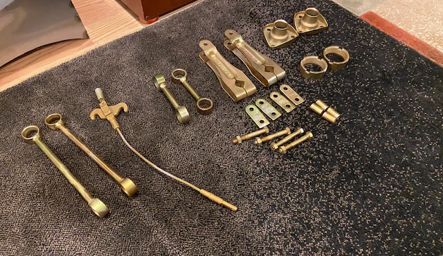
I can't seem to find a local plater that will quote the job without me schlepping part to them for quotation. I'm not in the mood to drive parts an hour across town as if we don't have the magic of the digital era.
My last known reliable shop that was literally 15 minutes from my house went out of busines a few years back.
If anyone around Detroit has a good recommendation for a shop that will quote off photos and is known to be reliable (i.e. good work and doesn't lose small parts), please post a response here.
It takes way too much time and effort to do this myself but at the moment I really have another viable alternative at the moment.
Posted by: Superhawk996 Dec 9 2021, 06:44 PM
Slowly getting warmed up to start some chassis welding again. But, like exercising, I can't just seem to jump right back in and start welding on critical structural components.
The warmup is to work on the section of the rear bulkhead behind the driver that has heavy pitting and some large pinholes thanks to the OEM NVH pad holding water. 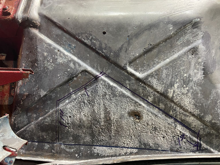
Back in the spring I tried to see if I could close one of the pinholes up with some really low amperage on the TIG. No dice.
Maybe it could be done with a copper backer but there really isn't much sense in just trying to plug the holes. The heavy, deep, pitting really necessitates new metal. 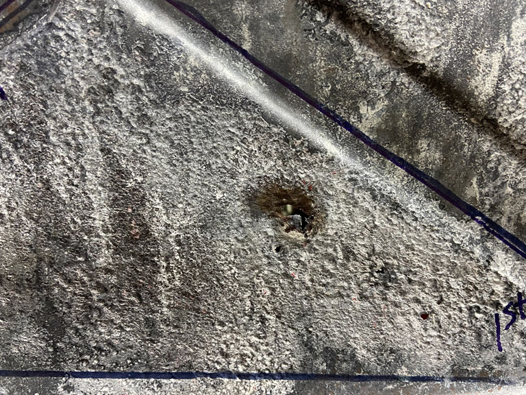
So I decided to pound out a small patch panel. 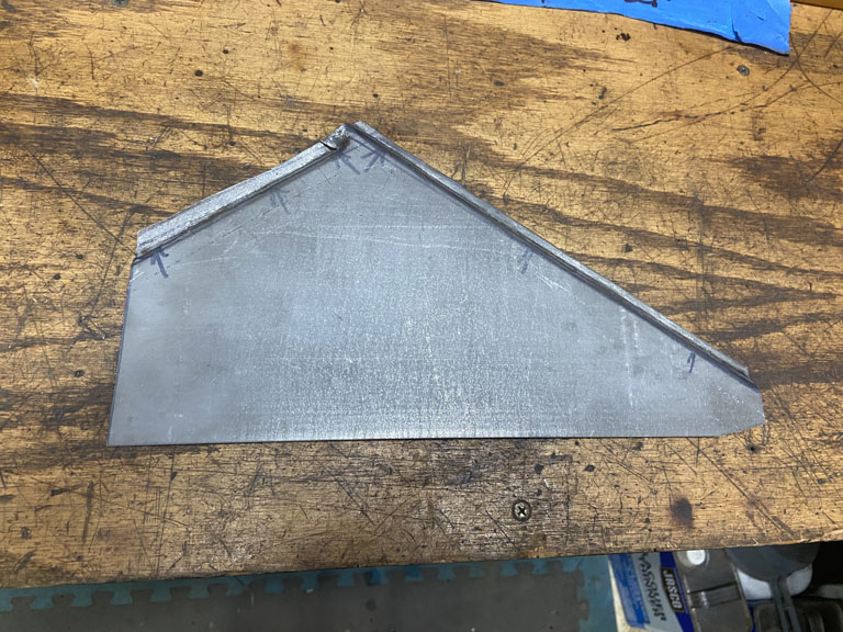
Initial rough fit looking good. Will tackle this over the weekend. 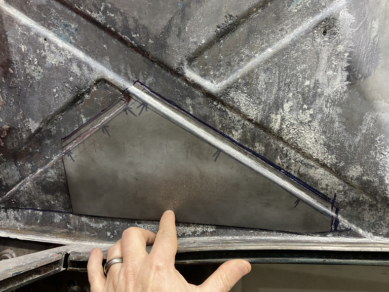
Posted by: Cairo94507 Dec 10 2021, 10:02 AM
Nice looking patch panel.
Posted by: Superhawk996 Dec 13 2021, 01:57 PM
So I'm pretty happy with the final installation of the bulkhead patch panel. After some careful fitting and very slow welding to prevent warping I think the character lines match nicely. 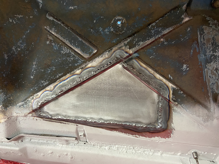
Used a copper backer to assure full pentration welds without blowing holes. 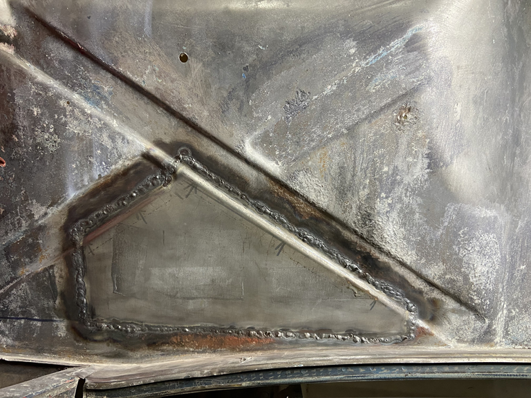
And now it's on to the next step. Clean up weld beads then need to go back and reapply Ospho to reactivate the Ospho previously left on the bulkhead for rust control. Then I can finish the cyclic process of applying Ospho, using a wire wheel to dig out rust from the pitting, and finally neutralizing the whole panel prior to a 2K primer. 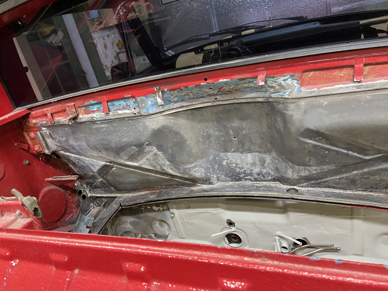
I also was able to knock out some bead blasting of a few other parts before I had to replace the bead. It sure leaves a nice finish but man, glass bead wears out so quickly. 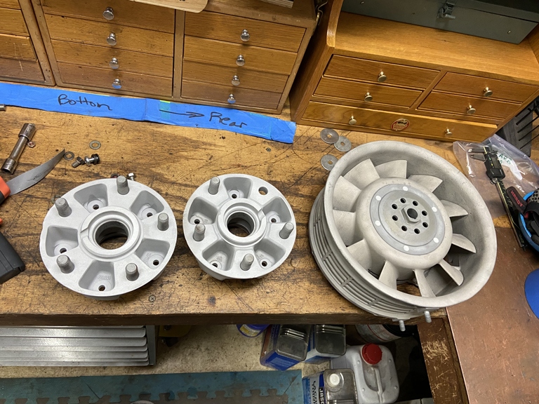
And then today - new hardware from BelMetric arrived. Time to restock my bolt cabinets looking ahead to a time when parts might actually start to go back on the car. That day is still a long way in the future but now I'm ready with proper yellow zinc hardware. 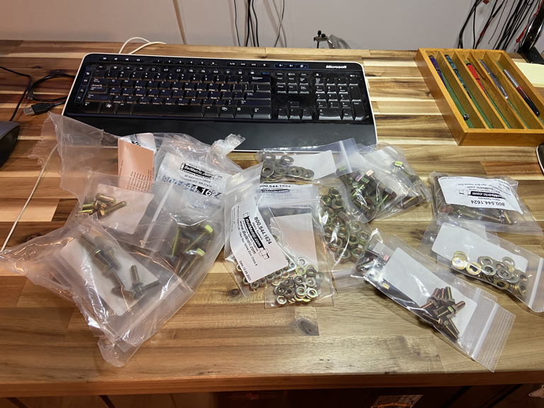
Posted by: Superhawk996 Dec 23 2021, 05:26 PM
Finally - A Major Milestone
Got the inner rear suspension console properly located (I think). 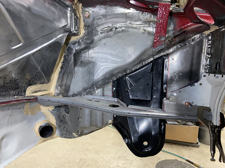
I've been stressing over how to do this the most accurately. Ultimately, I will install rear trailing arms to verify proper toe adjustment, and camber before I do final welding.
Jeff Hail's measurements triangulate off the hole in the middle of the rear bulkhead. Being a little OCD I wanted to eliminate all variability in how I use the tape measure.
I decided to machine up a little Bobbin that is a perfect fit to the OEM hole. In the center of the bobbin, there is a recess just big enough to nest a 1/8" welding rod. This allows me to mark the welding rod and get a much more accurate and repeatable measurement than I felt I could get with a tape measure.
Here is the little bobbin turned up on the lathe. 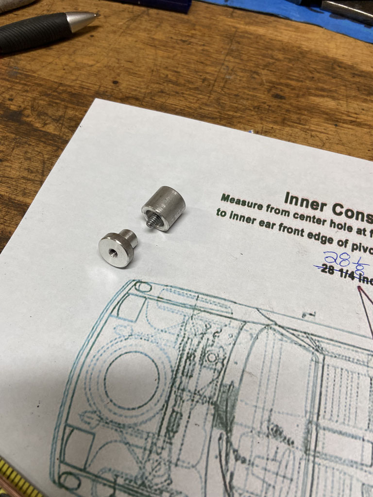
In position in the engine compartment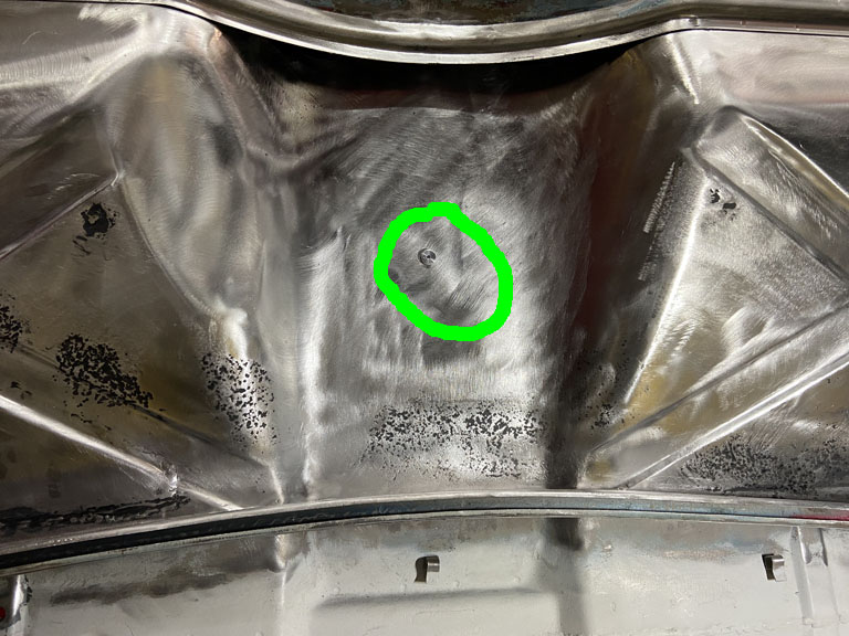
And how it is held in place on the interior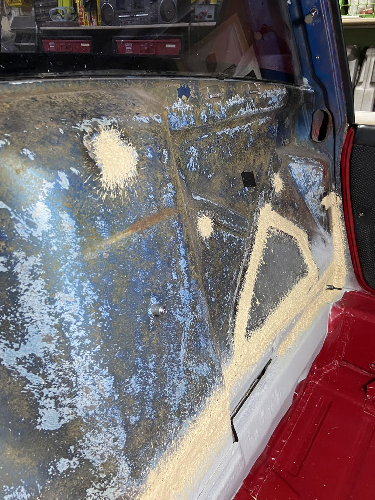
This worked out wonderfully in my opinion.
I worked with two pieces of welding rod. The first was cut to 33.5" and was used to verify the Jeff Hail dimensions to the outside of the console "ears". 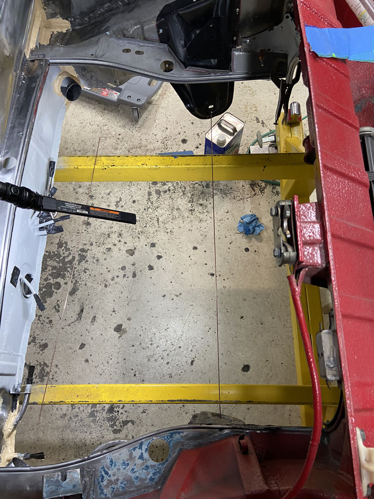
The second was used to measure from the bobbin to the leading edge of the suspension console ear though hole that the trailing arm pivot shaft goes though.
Starting with the Driver side, I got the same measurement as Jeff Hail had (28 1/8" + 1/8" for the bobbin) ==> 28 1/4". This is the same as I measured several years back when I first started this project. 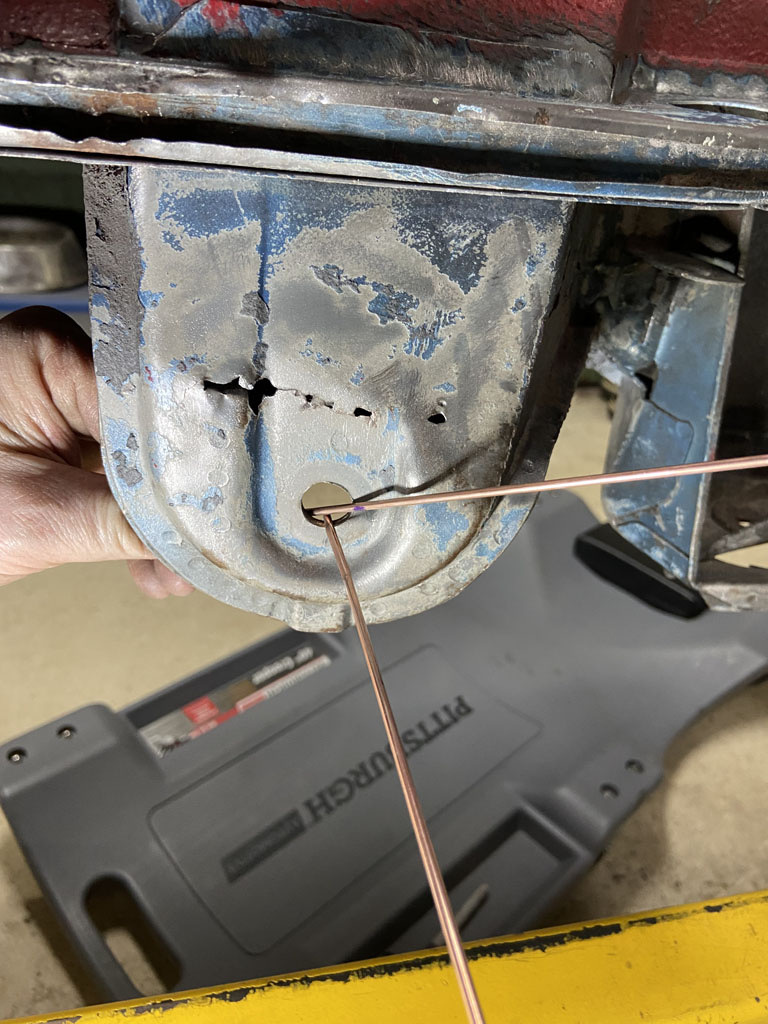
Then moved the console around until I duplicated the same measurements on the passenger side. 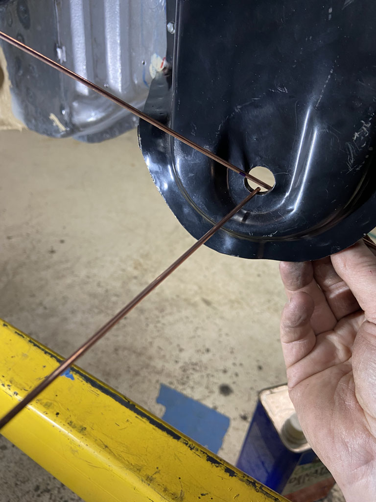
Then some double checks: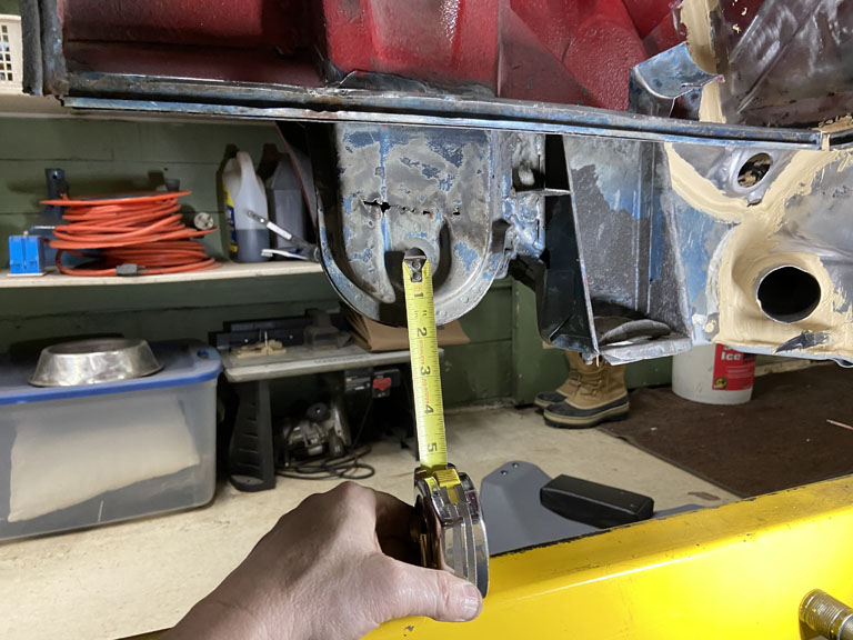
vs.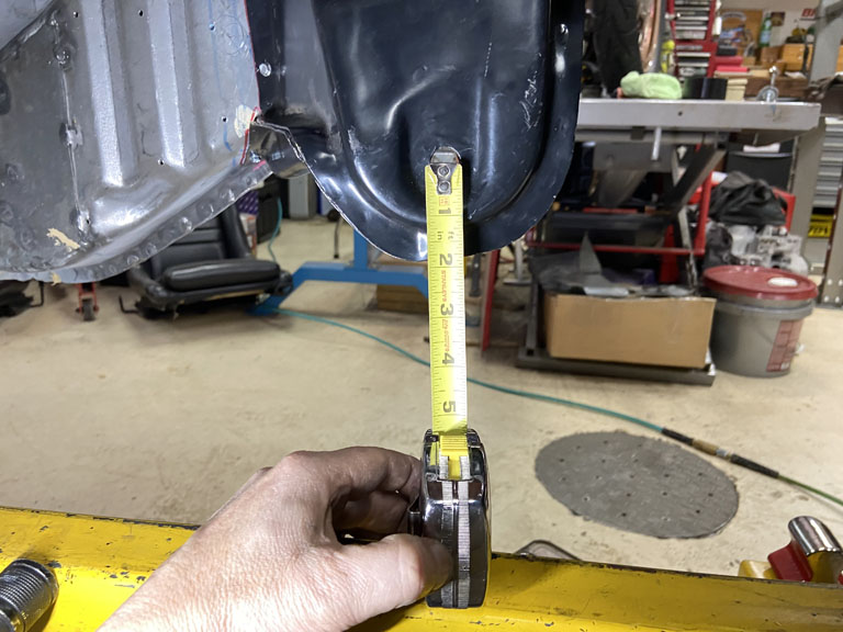
Then mocked up the engine compartment shelf and verified its position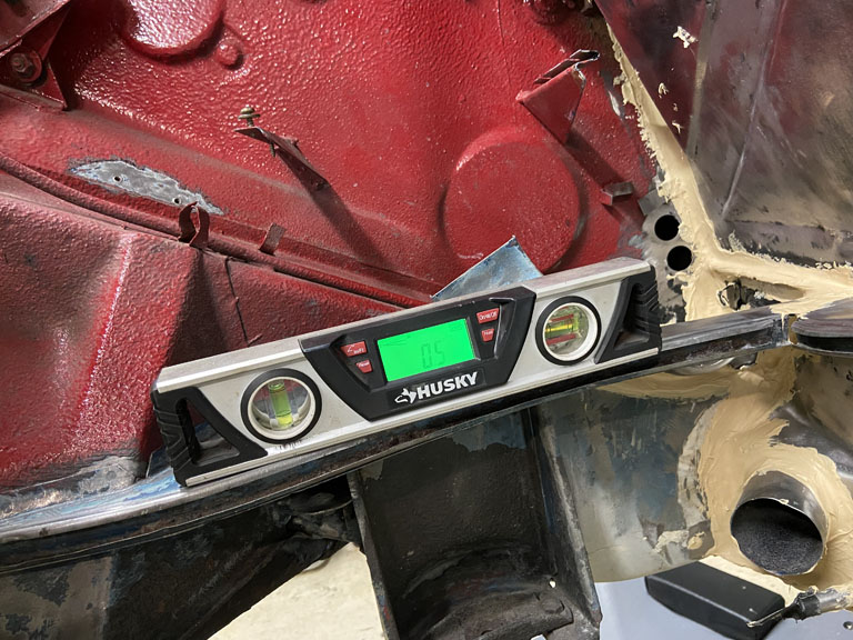
vs. 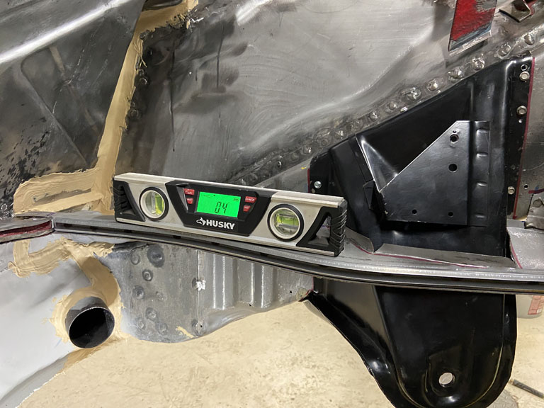
And then a quick check of overall shelf height. 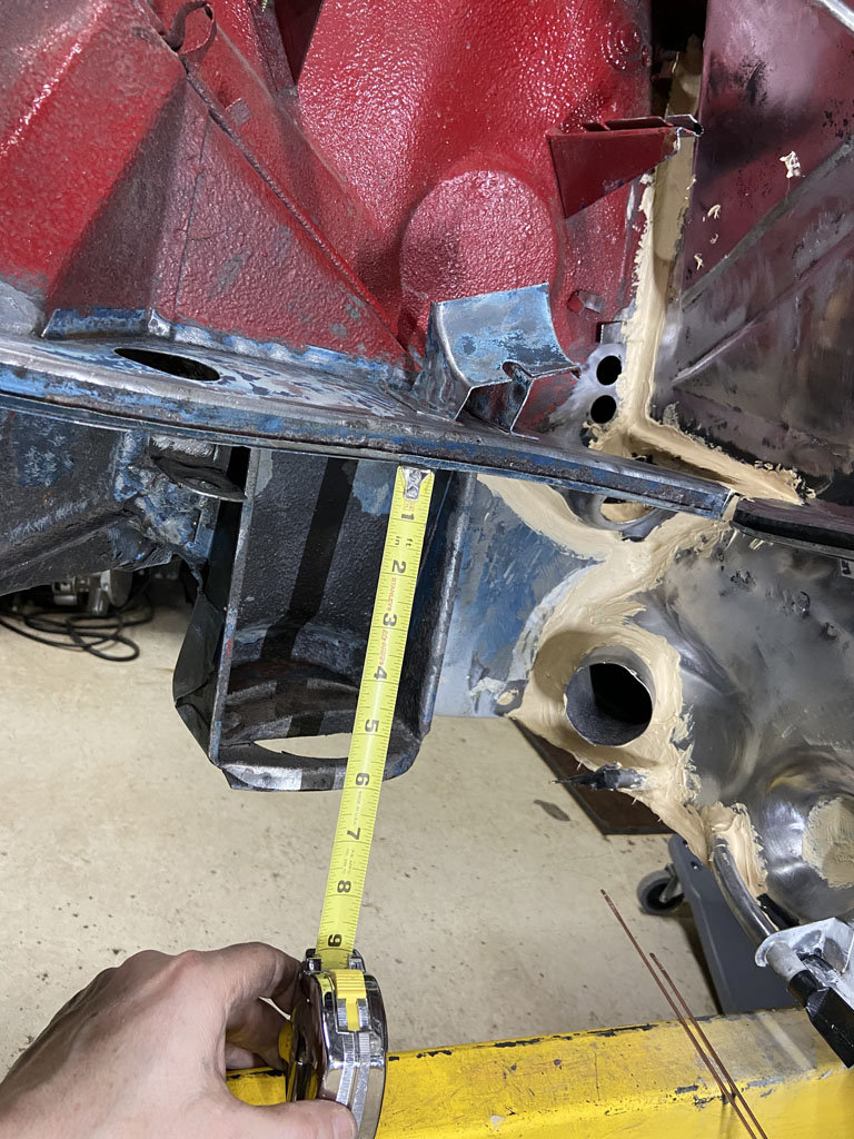
vs. 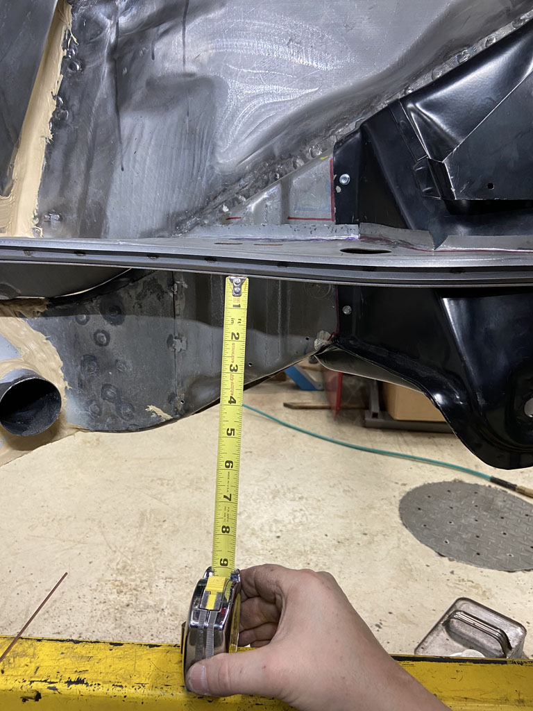
Took about 5 hours to get all this set up to my satisfaction. Can't wait to get around to getting this tack welded into position and then get the trailing arms mocked up!
Posted by: Superhawk996 Dec 23 2021, 05:39 PM
Front Control Arms
As a side project I knocked out the install of the Elephant Racing rubber front control arm bushings. 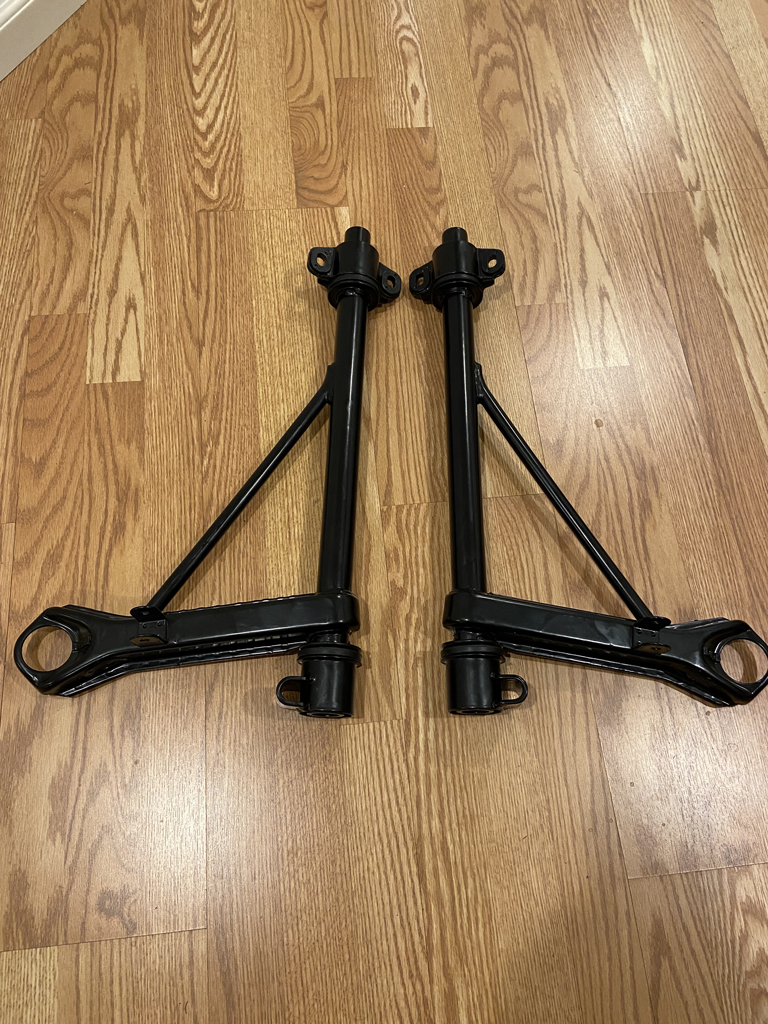
Very straight forward using their install tool and instructions. No drama on the install.
The only glitch is that I had the rear bushing retainers powder coated. Really should have simply re-plated them. The powder coating adds too much thickness to the outer diameter of the retainer for these to slip back into the front crossmember properly.
Argh! Nothing a little bit of work with a flap wheel won't fix but it will be a PITA. Learn from my mistake. Plate them - don't powdercoat!
Posted by: Jett Dec 23 2021, 06:06 PM
Great job! Very inspiring
Posted by: Superhawk996 Dec 29 2021, 10:46 AM
Forging Ahead:
Suspension console tacked welded in 5 places.
Time to start measuring before final welding. Started with a comparison to last know measurements. 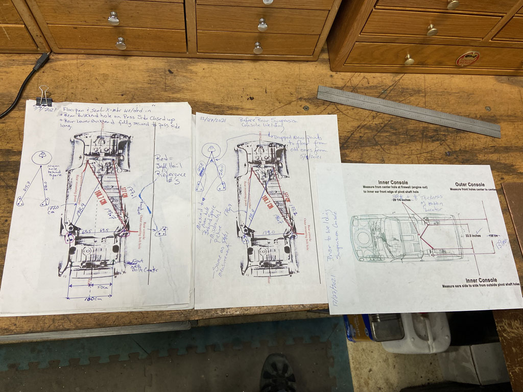
Then installed the Semi Trailing Arms (STA's) into a horizontal position for a baseline reference. Digital level at 0 degrees - measured at inside of STA right along the upper weld seam. 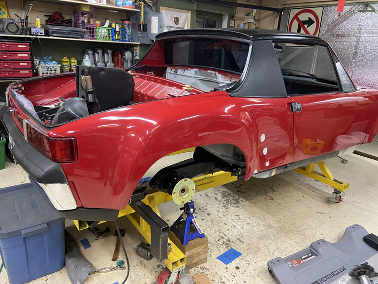
First check was of the driver side camber without shims which came in right at 89.9 degrees. This measurement will serve as baseline for comparison to the passenger side to be welded in. 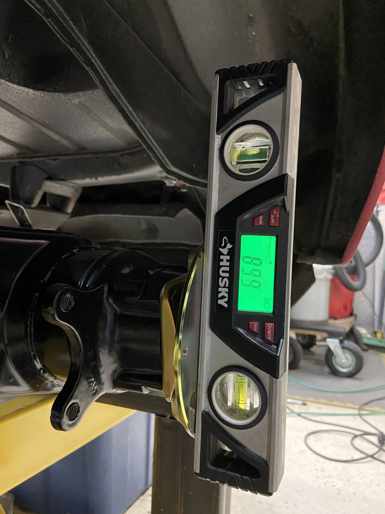
**Remember, no load on the car, and no deflection of the STA's so don't expect negative camber at this point in the game. Also remember that the STA's gain camber as they move into compression. I've arbitrarily chosen STA at horizontal as the baseline. I wish I had taken a ride height measurement between the hub center and the fender lip before I started long ago. If anyone has a car sitting on a 4 post hoist it would be swell if you could throw a digital level on the STA (inside along the weld seam) and let me know what angle the STA is at under normal ride height.
Passenger side came in at 89.4 degrees . This is not quite right as compared to driver side baseline. 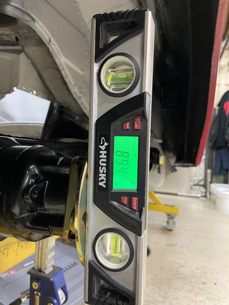
However, recall that during install of my outer suspension console, it ended up 5mm Higher in Z height than where it should be due to unplanned weld shrinkage. Not ideal but I knew I'd potentially have to add 5mm of "extra" shim to this side passenger side shim stack to compensate. Per the Peter Russek repair guide, 1mm of shim = 10 minutes of arc = 0.16 degrees. So if I have the outer approximately 4-5mm high in Z, that should mean that the passenger side would have 0.64 - 0.8 degrees negative camber MORE than the driver side. I'll take it. A little extra negative camber isn't a bad thing. As previously stated I can shim it out. However, since the math doens't line up perfectly, I need to go back and do a better measument of the outer suspension console in Z height to see if I can reconcile the disconnect between 0.64-0.8 predicted camber gain vs. the 0.5 degrees I see. Could be realted to my approximate 4-5mm measuremnt, or just be in the variance of my El Cheapo Husky brand digital level.
Onward.
Needed to verify that the wheelbase is the same between driver and passenger side.
This was done with a body trammel. I measured from the hole for the front Anti Roll Bar to the center of the rear hub. 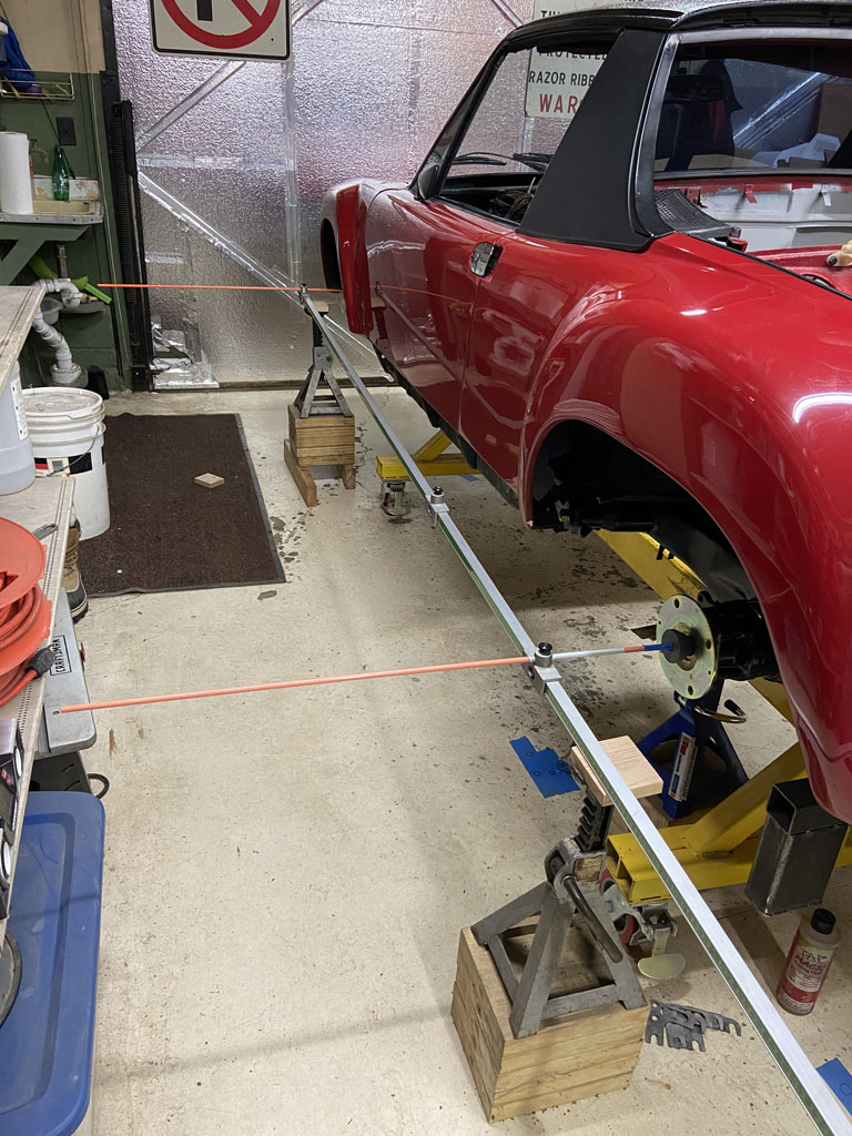
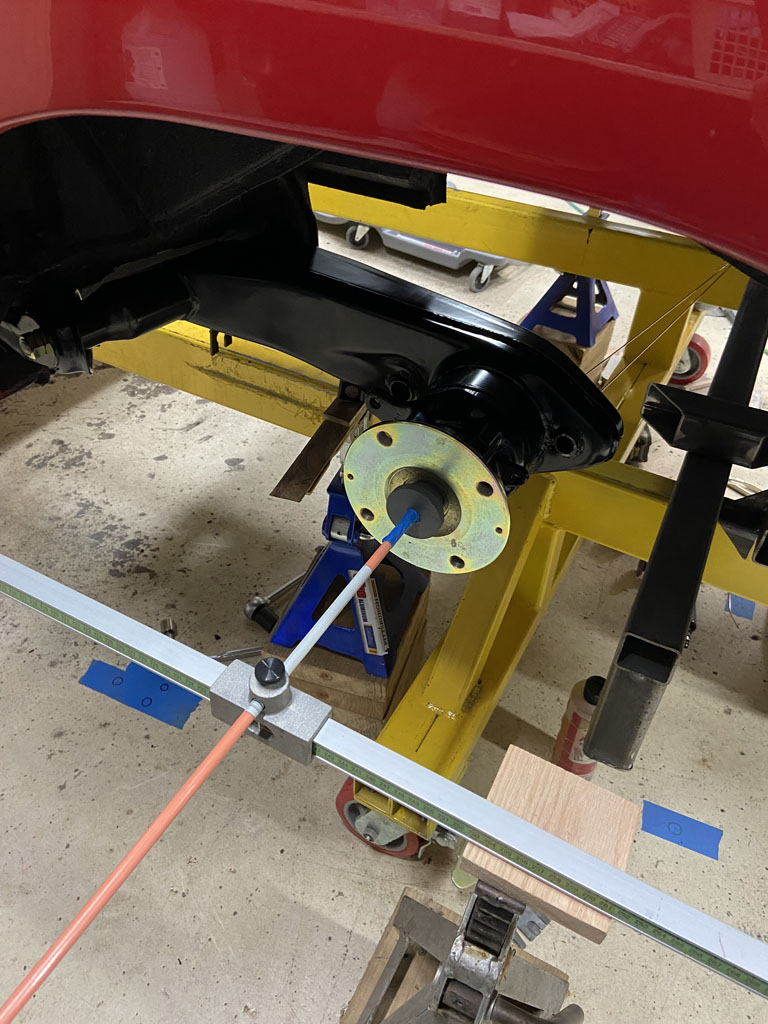
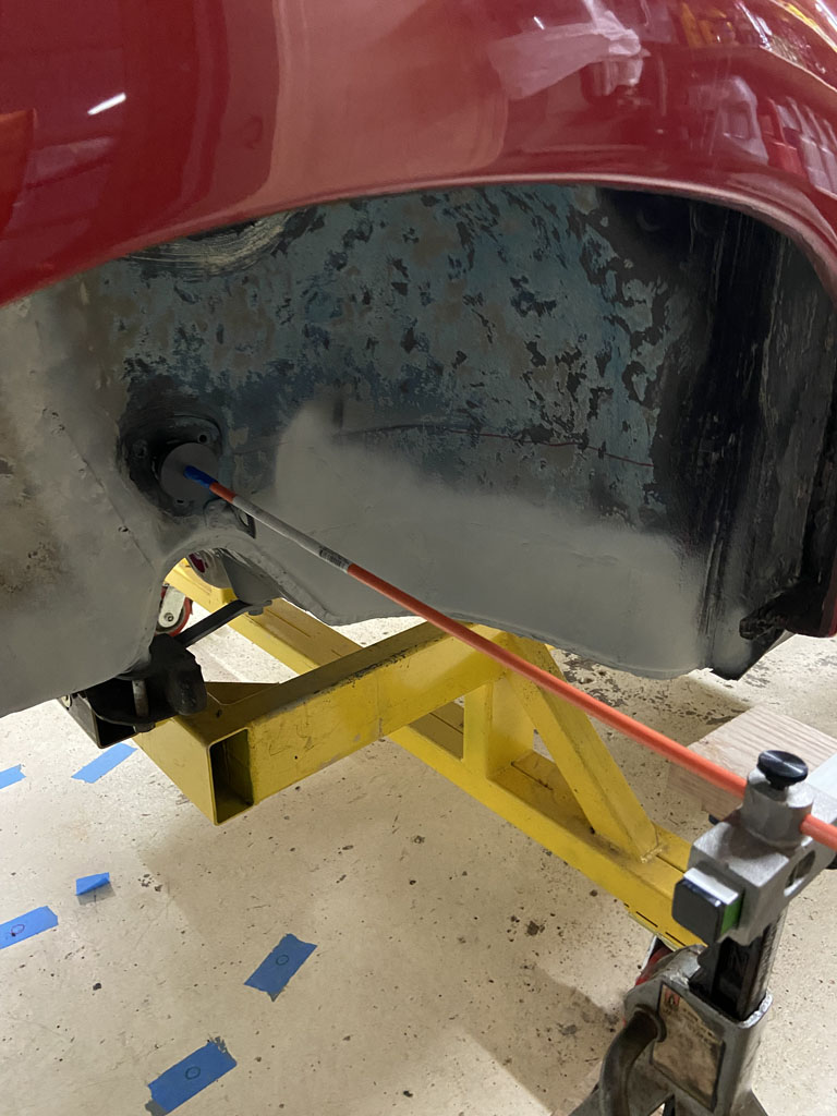
Without disturbing the trammel, I then flipped over to the driver side. 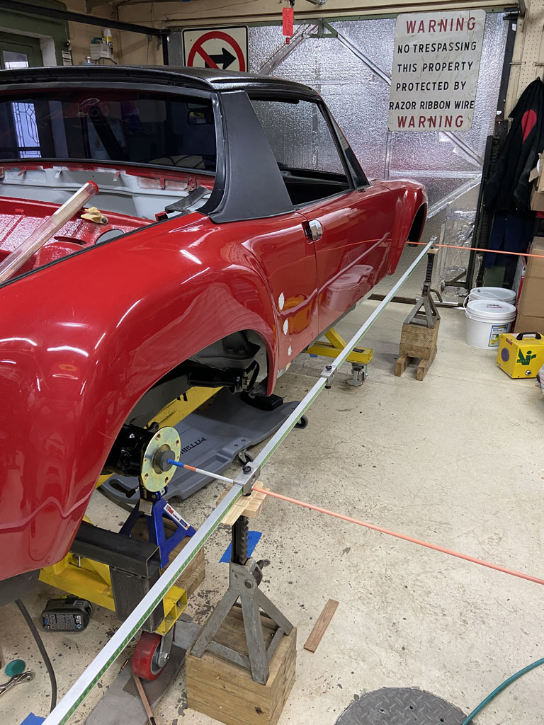
Success! Fits perfectly. Just in case it helps anyone in the future that reference measurement is 238cm. 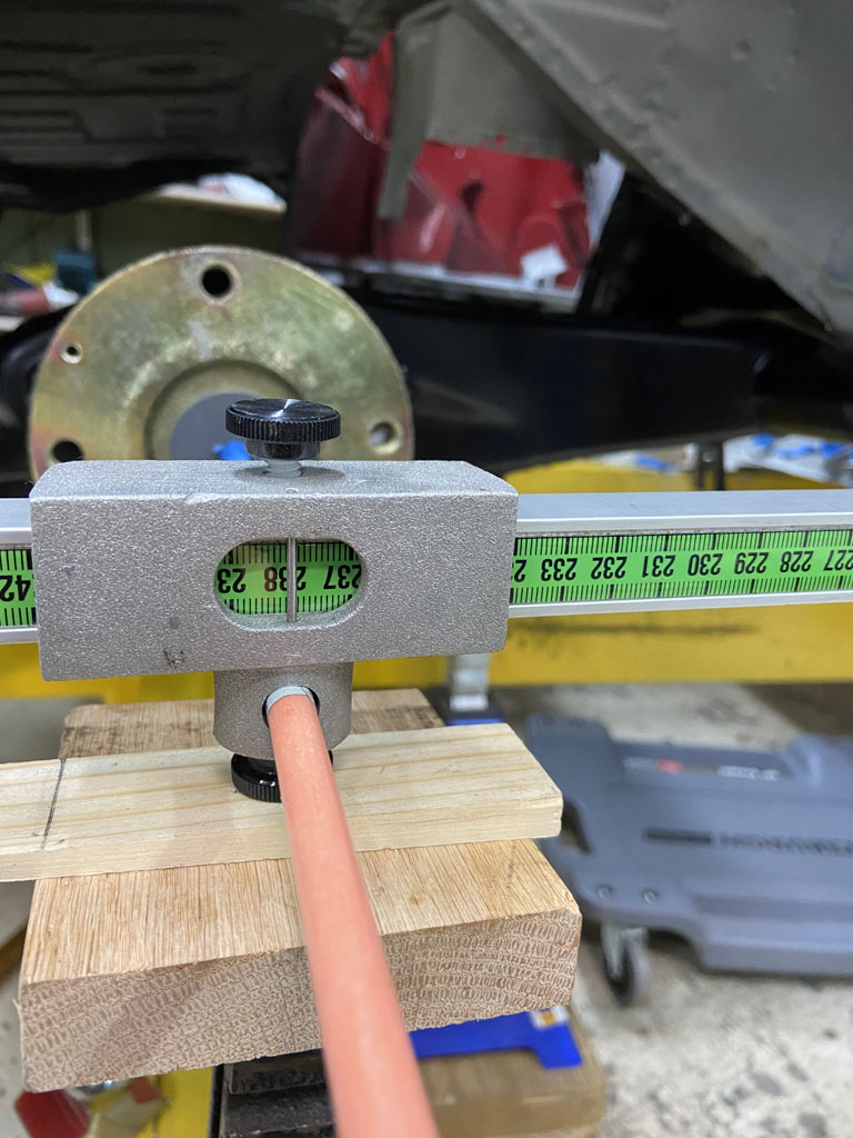
Then moved on to some quick body offset checks -- these are only approximate but wanted to make sure nothing was way out of place with the lateral location of the passenger side STA.
Driver side measured from tram bar to sheemetal in front of door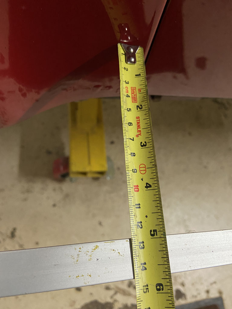
And again at rear of door. 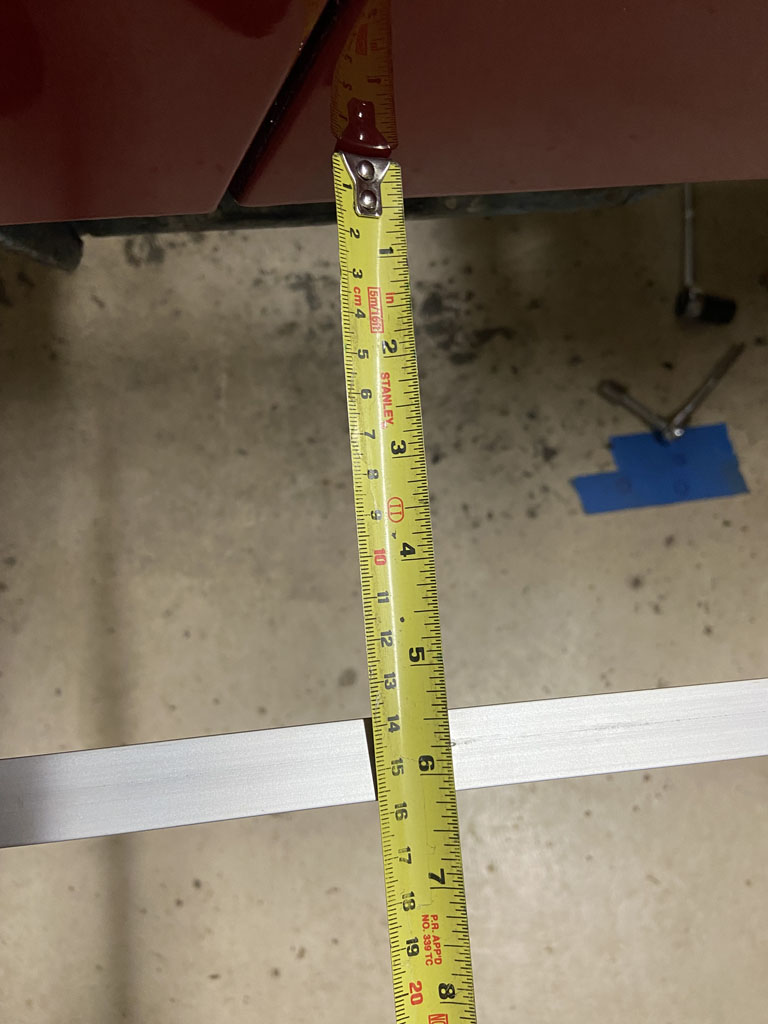
Repeated on passenger side front of door. 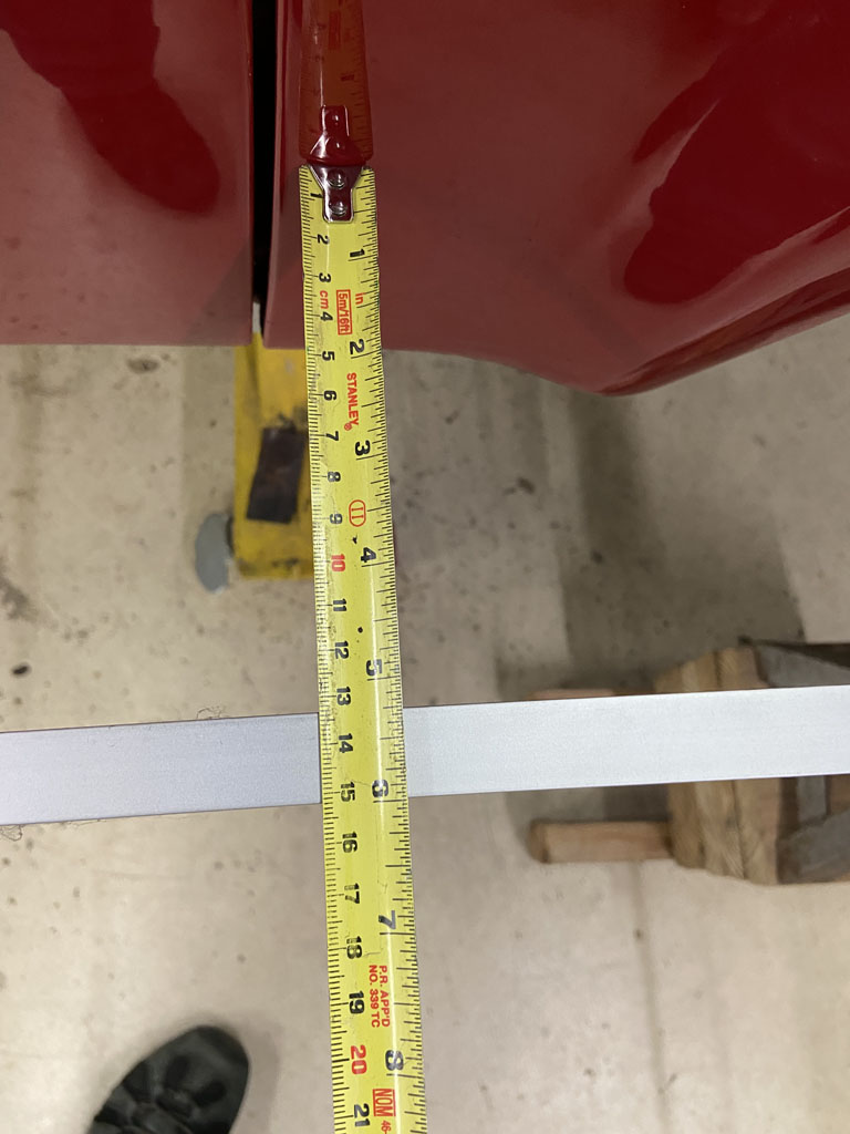
And passenger side rear of door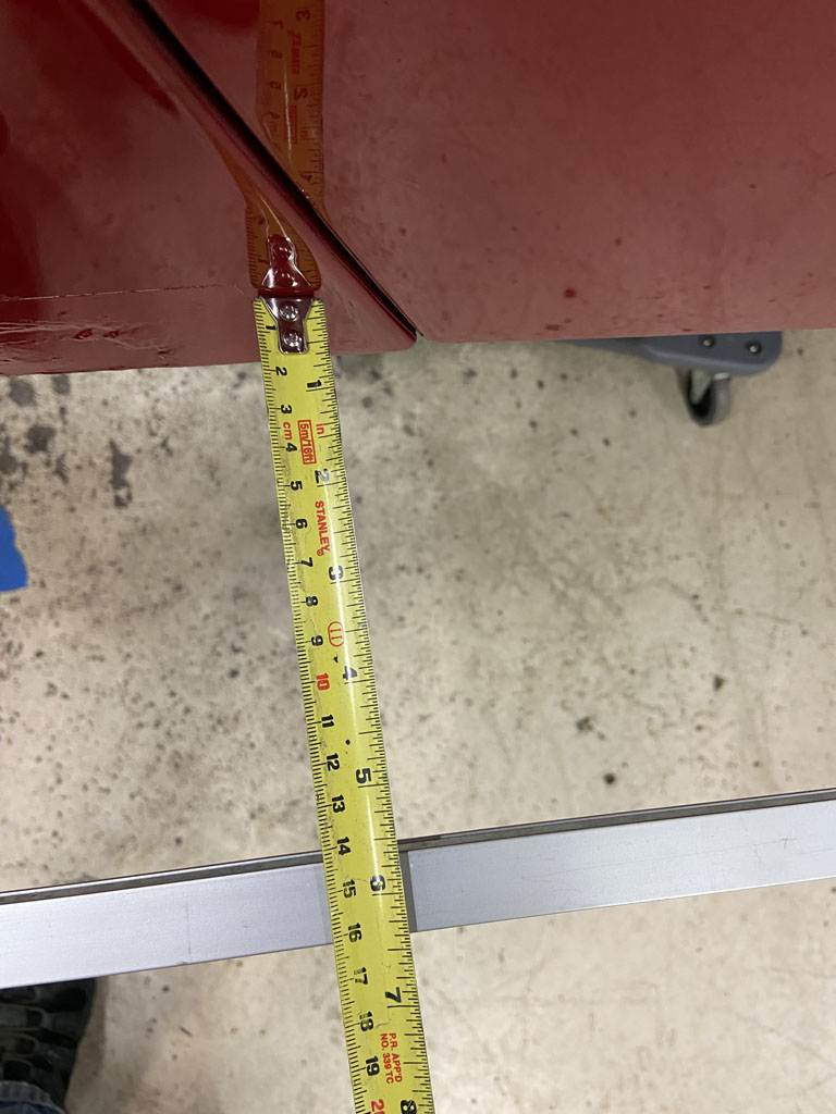
Not terrible. Overall about 6-7mm variance side to side. I don't think 6mm or 1/4" body variance of fender panels is out of the question in how outer sheetmetal attaches to the underbody structure and measurements that I've been so carefully been keeping track of.
Again, need to check this more carefully. I need to get front LCA's installed and then want to check track width at front compared to rear. Project for tomorrow.
Posted by: 930cabman Dec 29 2021, 05:16 PM
It's all numbers, but if not close to 100% it's wrong. Thank you for documenting this process, I will be fitting 4 new rear consoles at some point this winter and will refer to your process for sure.
Posted by: jesse7flying Dec 30 2021, 12:02 PM
Really nice work! I will certainly apply your lessons learned to my project.
Posted by: 930cabman Dec 30 2021, 02:25 PM
I am not by any stretch a computer guy, but the information being shared on 914World is probably the best of ANY other forum. As always some guys don't know their A%# from their elbow, but mostly this is invaluable stuff.
Thanks for posting Phil and Bob and Brent and ...................................
Happy New Year to all
Posted by: Superhawk996 Jan 1 2022, 11:21 AM
Checking Track Width, Wheelbase:
Dug out my front control arms and built them up with new Lemforder ball joints. 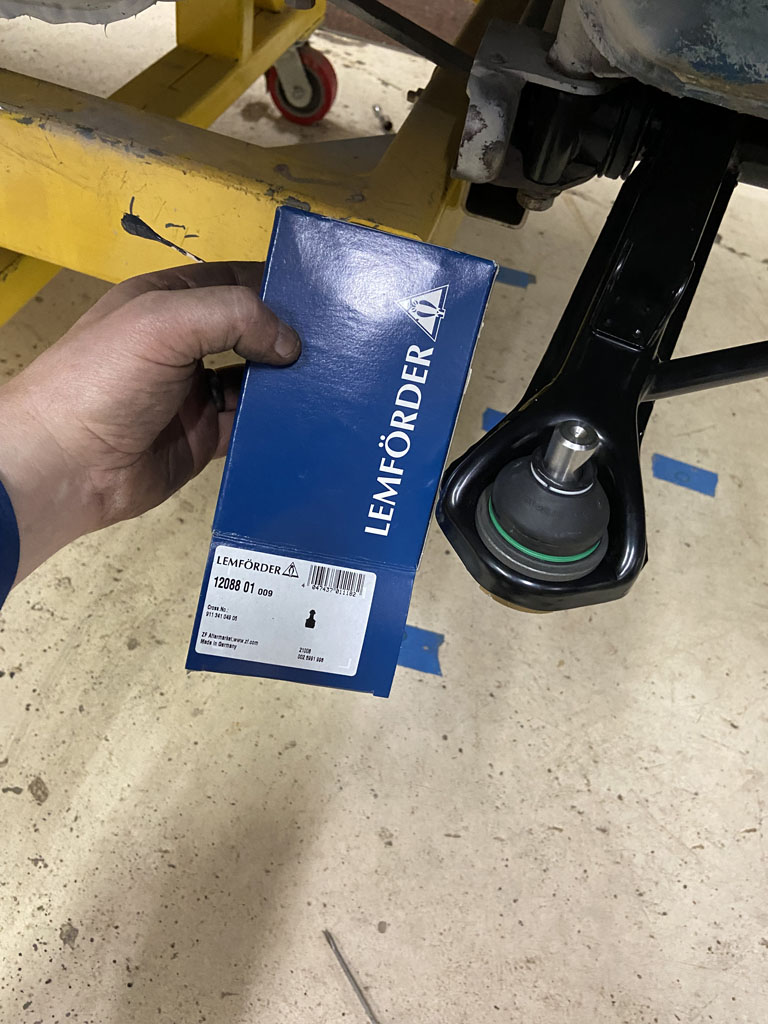
Added some new Boge inserts into the struts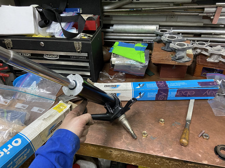
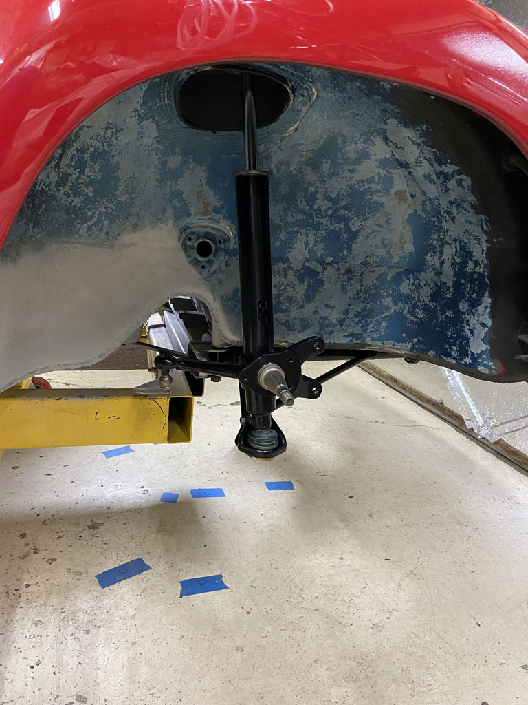
And we are off to the races to being able to measure track and wheel base directly after adding the front hub/rotor.
To measure front track, it is given at curb height. The suspension as installed ends up in rebound. Therefore, the front suspension needed to be jacked up near curb height to get a decent measurement.
Front track is listed as 1343mm with 5 1/2 x 15" wheels. But, in order to measure track off the rotor surface, we neeed to know the wheel offset. A bit of digging on the internet and PET shows the 5 1/2 x 15" wheel has an offset of 40mm.
So let's roll. Jacked up to near curb height. 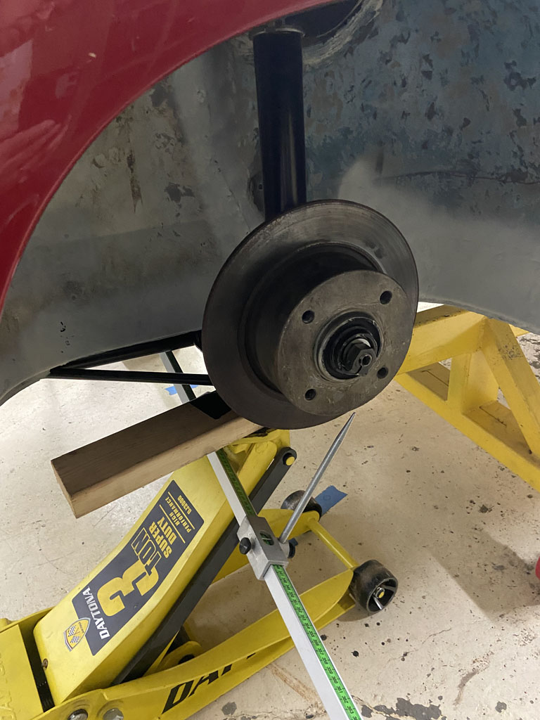
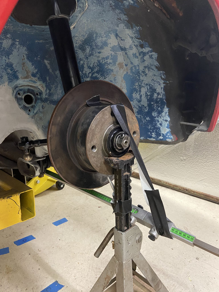
Direct measurement off the trammel is 1420mm. But remember, offset needs to accounted for to get track at the centerline of the wheel and tire.
So 1420mm - (40mm offset x 2) = 1340mm Looking good.
Next up rear track is listed as 1383mm with the 5 1/2" wheel.
Trammel measurement from rear rotor face to rear rotor face came up 1464mm.
Again accounting for offset 1464mm - 80mm = 1384mm.
Time to throw on some wheel & tires to see how things look.
Driver Side wheel to the sheetmetal fender flange that the rocker panel sits into. 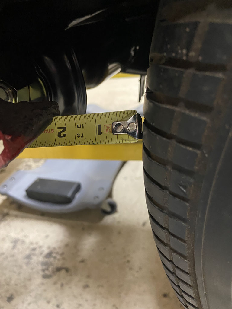
and comparing to passenger side 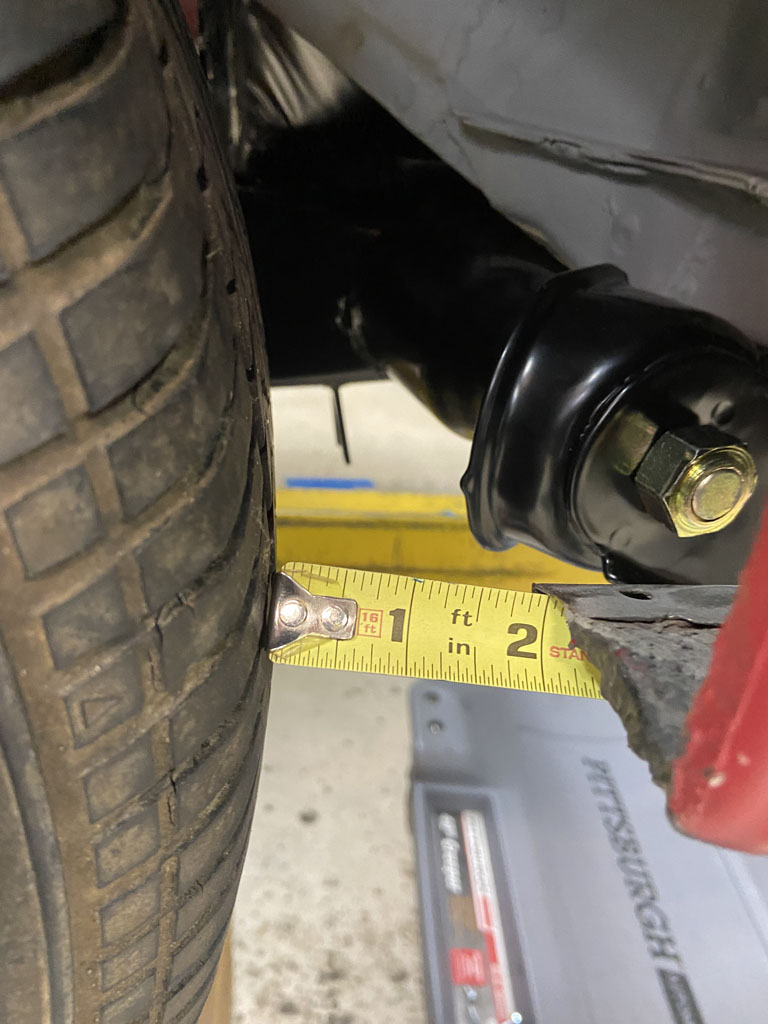
Right on! 
Let's check the wheelbase. Wheel base is listed as 2450mm. 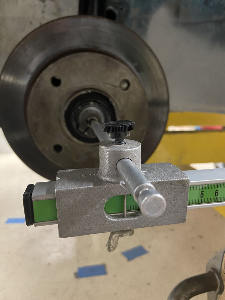
Driver side right on the money! 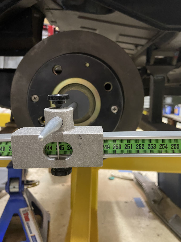
Passenger side: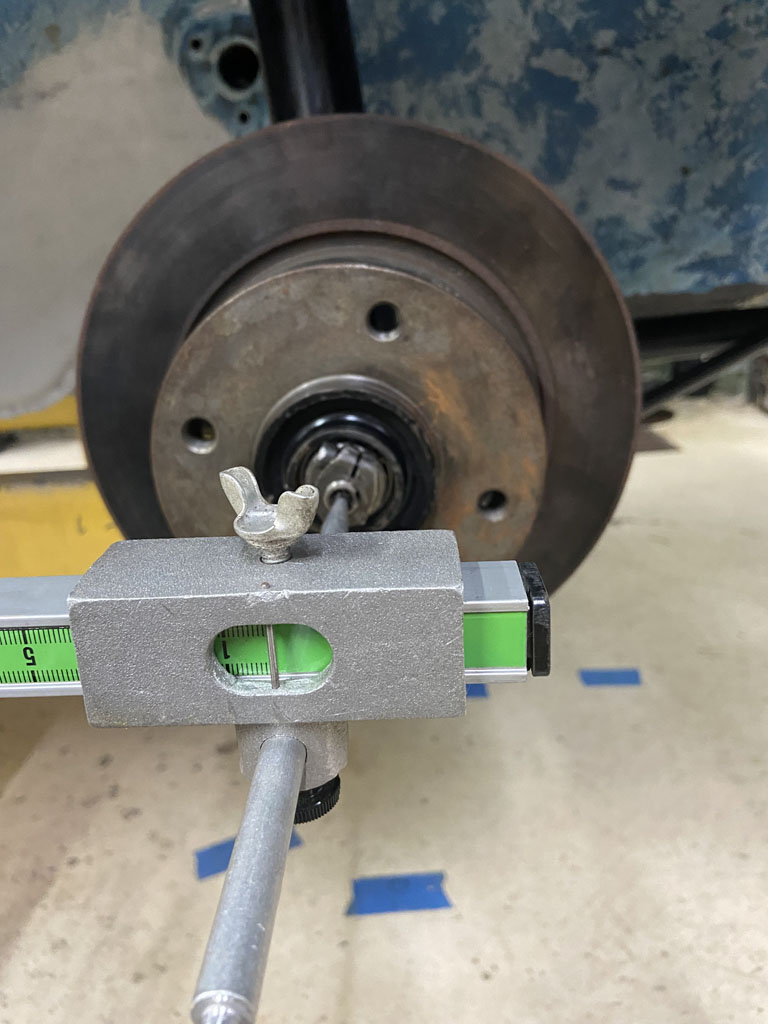
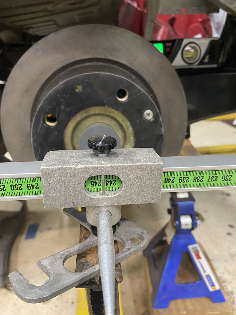
So here we have 2445mm. Looks like about 5mm different than passenger side. But, there is no need to panic. Remember that both sides measured the same from front ARB hole to rear hub centeline. I trust this measurement way more since there is only one degree of freedom (where the STA is) vs this direct wheelbase measurement that has two degress of freedom (STA location + position of the front strut spindle).
Even if there were a full 5mm of variance in wheelbase between driver and passenger side, I could live with that but the reality is that wheel base will vary slightly side to side as we do the final alignment to set rear toe-in.
So as a final reality check, I did move the rear wheels between maximum toe in and toe out doing a crude check from tire center line to centerline with a tap measure.
Looks like I can get a maximum toe in 7/16" and maximum toe out of 1/4". As an engineer I love symetry but in this case, we would never want toe out so I'll live with it.
And finally, I wanted to take a rough look at camber gain.
Before doing that recall, that I started out with a smidge more camber on the passenger side due to weld shrink when I put in the outer suspension console. I went back and shimmed passenger side until I had the same 89.9 degrees on the rear hub.
That took 4.3mm of shim. So that answers my previous doubt about how much higer in Z the outer console was. Not terrible. I would have rather been right on the money but I can live with having to have an "extra" 4.3 mm of shim on the passenger side.
So the math does work out (roughly). Per the Russek notes, 1mm of shim = 10' of camber = 0.16 degrees. So knowing that I'm 4.3mm high in Z, I should have an extra 0.68 degrees of camber on the passenger side. I had 0.5 degrees more. I'll chalk the other 0.18 degrees of error up to build variation, measurement error, and accuracy limitation & repeatability of my Husky angle gauge.
I then pushed the rear STA's up to a point where I thought they looked like they were closer to curb height. I then took a quick look at camber gained.
2 degrees on Driver Side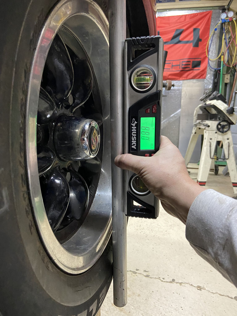
2.2 degrees on Passenger Side. 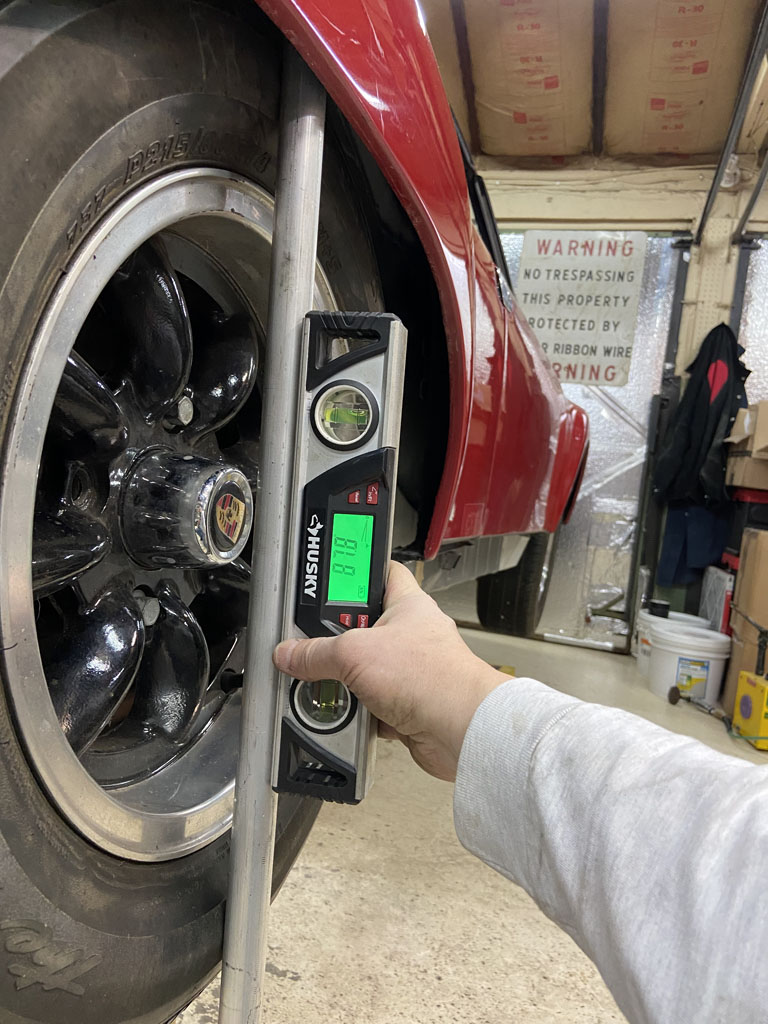
Loving it. So at this point, we've verified that camber gain is working properly (increasing as wheel goes into compression), that it is pretty close to symetrical side to side, and that near curb height we have more than enough camber. We would then add shims to take camber out closer to spec at curb.
Feeling really good about proceeding with final welding of the inner suspension console today.
Posted by: Superhawk996 Jan 3 2022, 05:15 PM
Well, I'm comitted now: 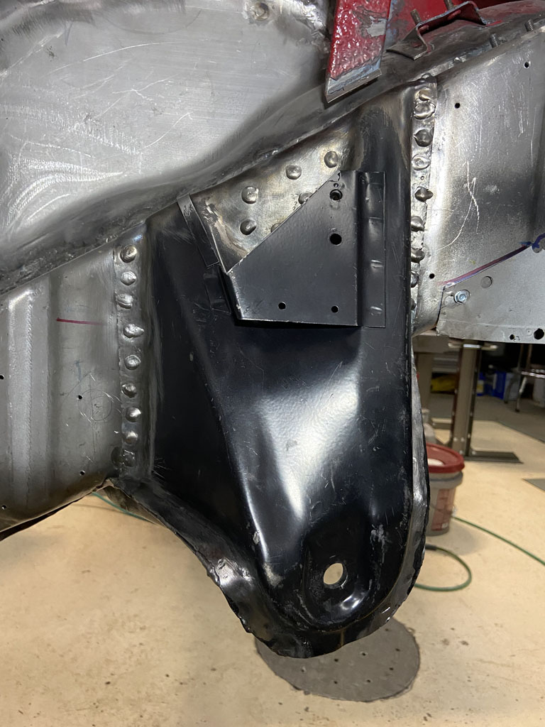
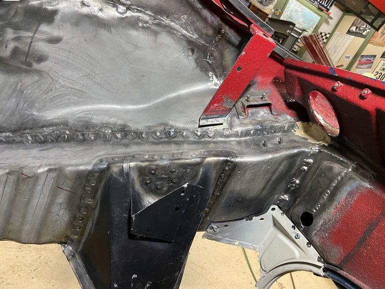
As usual there was a catch.
Why I didn't remove the old remnant of the "bow tie" from the outer suspension console when it was on the bench is beyond me. Oh well much more fun to work on it upside down under the car. 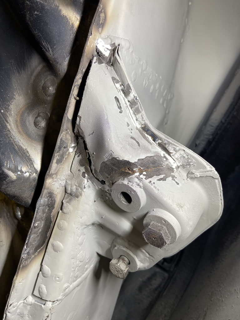
When I finally got it removed, I was impressed to find the black Eastwood Frame Coating and rust converter was still in between the sheetmetal layers and had held up well to all the welding that was done while installing the outer suspension console. 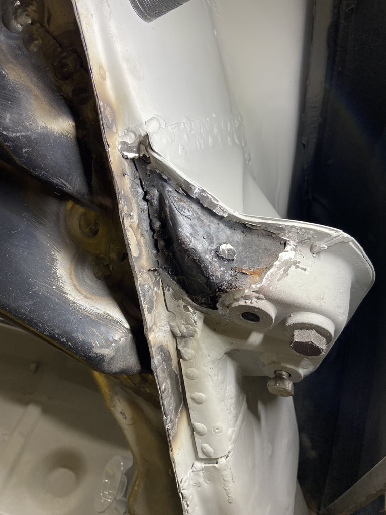
Although I had wanted to button on up and have the bow ties welded in place by end of last night. It just wasn't in the cards.
OEM remnant piece I measured was 2.0mm thick (0.080"). These laser cut parts are 0.100". Very tough to form. The two piece bow tie that is mocked up and spot welded is easy. The one piece part is much tougher. I've bent it about as close as my little 6" vice mounted press brake will get it. Going to have to break out the serious heat to finish forming it. 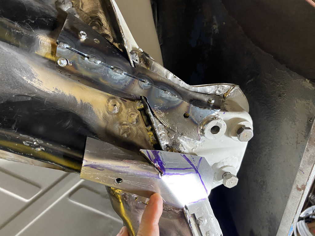
These pieces are way better than having to start from scratch, create templates, source the material, and then cut them out with a band saw. Many thanks to Cary (RIP) for designing them, 914Rubber @http://www.914world.com/bbs2/index.php?showuser=3348 for making them, and @http://www.914world.com/bbs2/index.php?showuser=10825 for donating these to me.
As a plea for the future:
Sure would be great to have the parts made from 0.080" material - don't need the extra weight of 0.100" thick material
Sure would be great to have these pre-stamped into the proper shape. I'd glady have paid some decent money to not be fiddling with forming these from flat sheet stock.
@http://www.914world.com/bbs2/index.php?showuser=8858
Posted by: Mikey914 Jan 4 2022, 12:07 AM
Well, I'm comitted now:
As usual there was a catch.
Why I didn't remove the old remnant of the "bow tie" from the outer suspension console when it was on the bench is beyond me.
Oh well much more fun to work on it upside down under the car. When I finally got it removed, I was impressed to find the black Eastwood Frame Coating and rust converter was still in between the sheetmetal layers and had held up well to all the welding that was done while installing the outer suspension console.
Although I had wanted to button on up and have the bow ties welded in place by end of last night. It just wasn't in the cards.
OEM remnant piece I measured was 2.0mm thick (0.080"). These laser cut parts are 0.100". Very tough to form. The two piece bow tie that is mocked up and spot welded is easy. The one piece part is much tougher. I've bent it about as close as my little 6" vice mounted press brake will get it. Going to have to break out the serious heat to finish forming it.
These pieces are way better than having to start from scratch, create templates, source the material, and then cut them out with a band saw. Many thanks to Cary (RIP) for designing them, 914Rubber @http://www.914world.com/bbs2/index.php?showuser=3348 for making them, and @http://www.914world.com/bbs2/index.php?showuser=10825 for donating these to me.
As a plea for the future:
Sure would be great to have the parts made from 0.080" material - don't need the extra weight of 0.100" thick material
Sure would be great to have these pre-stamped into the proper shape. I'd glady have paid some decent money to not be fiddling with forming these from flat sheet stock.
@http://www.914world.com/bbs2/index.php?showuser=8858
Pretty sure I can form these to be easy to install. Next run when we drop down.080 it will be easier.
Mark
Posted by: peteyd Jan 4 2022, 09:25 AM
As a plea for the future:
Sure would be great to have the parts made from 0.080" material - don't need the extra weight of 0.100" thick material
Sure would be great to have these pre-stamped into the proper shape. I'd glady have paid some decent money to not be fiddling with forming these from flat sheet stock.
@http://www.914world.com/bbs2/index.php?showuser=8858
I would have measured the originals that we scanned and made the tooling with the correct clearances to match the originals.
When we get back to this tooling, we will definitely be making them to the same thickness as Porsche did.
Pete
Posted by: Superhawk996 Jan 13 2022, 08:05 AM
Suspension console is nearly complete.
Finished welding in the "bow tie" console reinforcements that tie the outer console to the inner. Yeah, the welding sure isn't the stack of dimes look. It is so hard doing all the out of position welding. Much of it is overhead. Haven't quite come up with a good way to keep my arms raised for long periods of time without getting shaky. Guess I need to workout more!
I drizzled a little Eastwood Frame coating down into the gaps to prevent rust between the steel layers. It is very thin and really does creep into gaps. Anyway sprayed some into the gaps until it came out in other places. 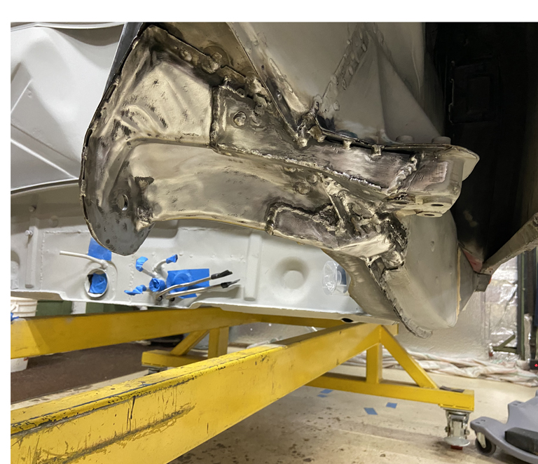
@http://www.914world.com/bbs2/index.php?showuser=24690 As a side note; mock up the suspension before final welding of the bow ties. I found that the outer console reinfocement was too long and the thickess of it was restricting range of toe-in adjustment. Had to trim the bow tie back about 3/8" so that it provided proper cleaance to the outer trailing arm pivot. Not a big deal but mock up of the trailing arm saved the day before I found this out too late at final assembly time.
Then moved my attention to the install of the Tangerine Racing inner suspension console reinforcements. I purchased them pre-shaped which does speed things up a little bit. However, there is still fine tuning that needs to be done as these get welded in. 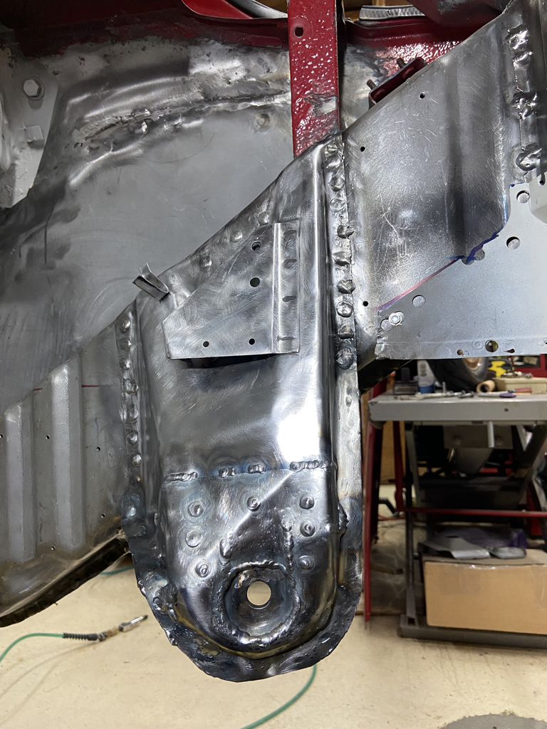
Still need to finish a couple perimeter welds on this and then repeat the Eastwood rust coating. Will then seal the perimeter with a little seam sealer. Will then shoot it with some 2K primer.
One thing that I screwed up -- I should have sand blasted the suspension console before the installation. When welding on it I was constantly getting massive smoke as the paint inside the console burned away. Very annoying.
Plus, now I'm thinking there is very little corrosion protection left inside the inner suspension console.
I'm thining I'm going to drill a small hole about 5/32" just big enough to get the Eastwood spray tube in there and then reshoot the inside of the console with the rust inhibiting coating. Then weld up the 5/32" hole. Sure there will be some localized burn away in the vicinity of the hole, but I'm thinking that this still has to be better protection than what little must be left of the original paint. Live & learn!
Next up: Repair the stress cracked Driver side inner suspension console and then put the other Tangerine stiffener over the driver side.
Posted by: Cairo94507 Jan 13 2022, 09:39 AM
Amazing work.
Posted by: Superhawk996 Jan 14 2022, 08:15 AM
Public Service Announcment
Keep your drain holes clean & clear to allow moisture to drain properly.
The rear suspension consoles on 914's have always been prone to rust, stress cracking, and subsequent failure. Especially as loads increase from spirited driving, Autocross, and the worst case, racing with sticky tires.
In the case of my chassis I suspect that it has about 160K miles on it. Stress cracking in this area wouldn't be surprising just with normal wear and tear.
When I first started rustoration, I quickly found evidence of stress cracking on the driver side inner console ear. Initially this area looked fine and was covered with undercoating that seems to have been applied to so many of these cars over the years. Not sure if someone was trying to hide it, or maybe the metal was just thin already and they simply sprayed over it not even knowing. This is how it looked after cleaning off the undercoating with a wire flail wheel. 
This stress cracking comes from 3 issues:
1) The stamping appears to be thinning in this area as the metal "flows" during pressing. When metal is stretched though the tight radius corners like this area has the material thins out.
2) This console ear bears lateral loads during corning leading to some higher material stress and cyclical fatigue.
3) Rust compromises the console from the inside out. It can look fine on the outside but be paper thin metal.
In my case, I started by cutting out the stress cracked area and verifying that I got back to an area that has full thickness metal. 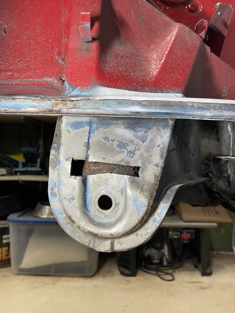
When I got the material cut out I made another upleaseant discovery. The ear is full of sand, rust particles, etc., and the drain hole is completely obstructed. You should be able to get a piece of 1/16" welding rod inserted up though the bottom drain to ensure its clear. No-go. 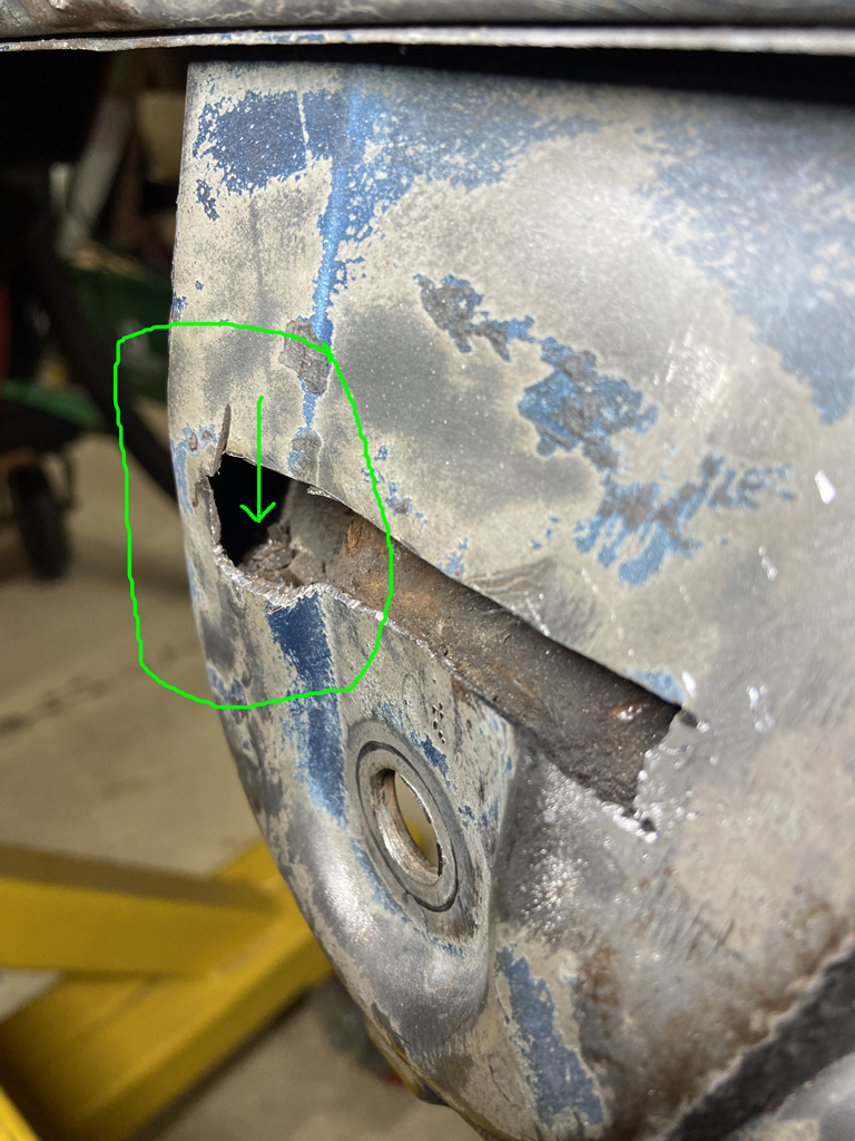
Getting my drain cleared proved to be really tough. Usually this can be done just by using a pick tool or wiggling the welding rod around and evenually the blockage can be cleared.
When I got the drain hole clear with a heavy duty pick, I still couldn't get the welding rod to insert all the way up into the console. The stuff up in there was hard as cement and not budging.
Time to get more agressive.
Progressively started drilling 1/8" holes and using the pick and welding rod to break up the debris that was blocking the lower channel. From the picture below you get an idea of how it had to be broken up in little sections. 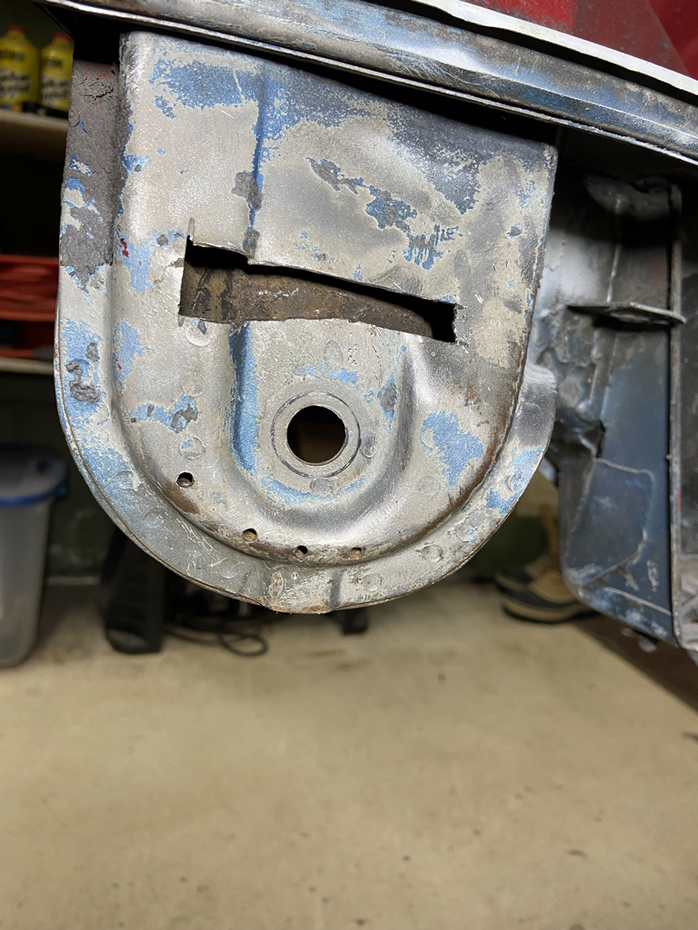
After about 90 minutes of fiddling around, I was able to get all the obstuction clear on both sides of the drain so that it will drain water freely.
Moral of the story: Keep your drain holes cleared as part of annual maintenance. Not just these drains, do all of them including the longs.
In my case, this wasn't a terribly big deal. I'll now have to weld up the holes in addition to fixing the stress cracked portion that originally started this job. At the end, it will get the Tangerine Racing reinfocement put over the whole area for some added strength.
Posted by: Superhawk996 Jan 17 2022, 11:25 AM
Driver side Console Repair Complete
Quick photos of repair to the inner console ear that was cracked.
Fitted and tacked in new metal. 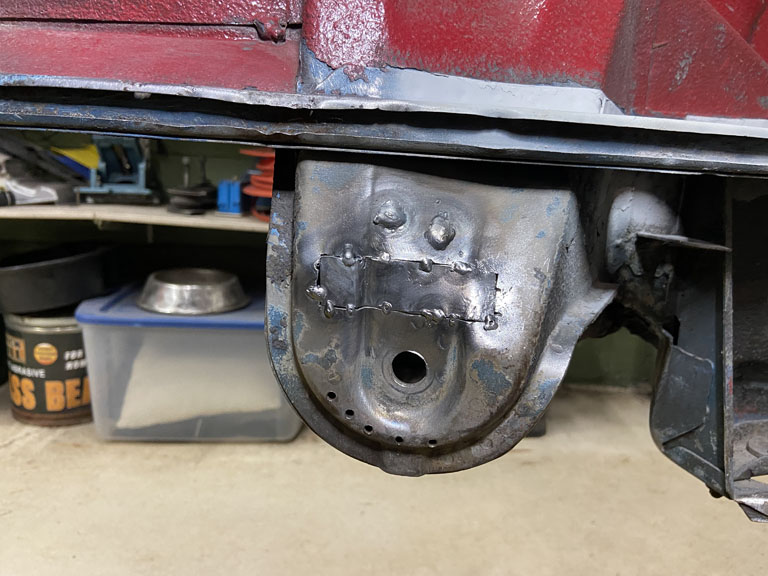
Welded it up.
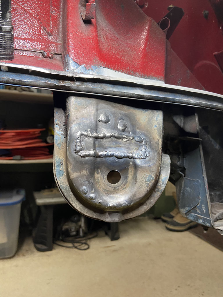
Ground down the weld beads a bit. Wish I could get the bead height just right. Every now and then I get the perfect combination of gap between metal, body position, and weld technique to lay in a bead that has 100% penetration but without excess bead. Puts a smile of my face. Just wish I could to it repeatedly at will even in out of postion welding. Have also come to the conclusion that I need to improve my left hand and out of postion welding skills. 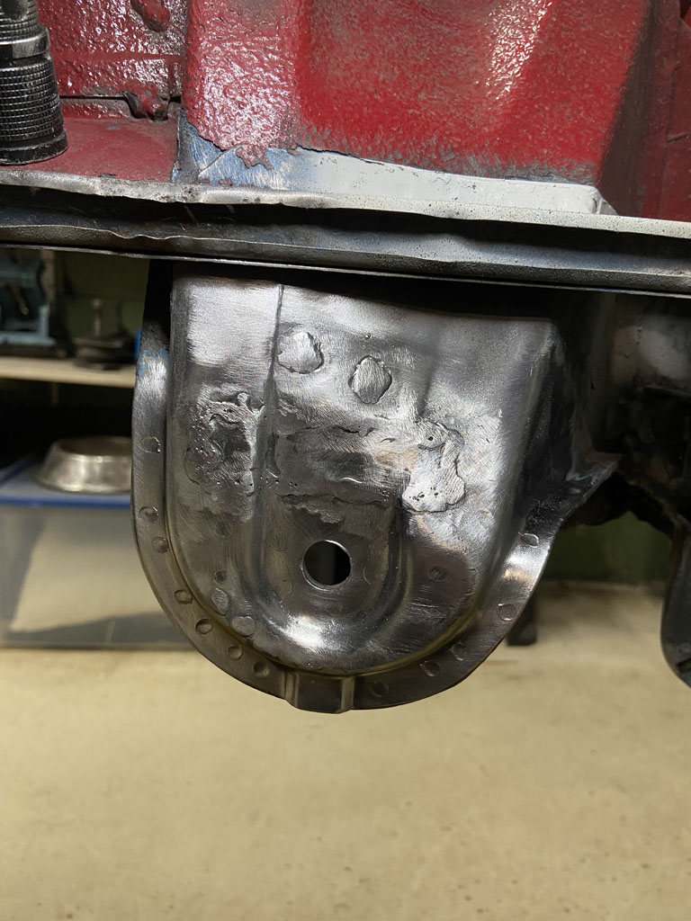
And finally put in the Tangerine Racing Stiffner. We are lucky to have vendors like Tangerine, 914Rubber, and others supporting us with niche parts like these that didn't exist last time I was working on 914's. 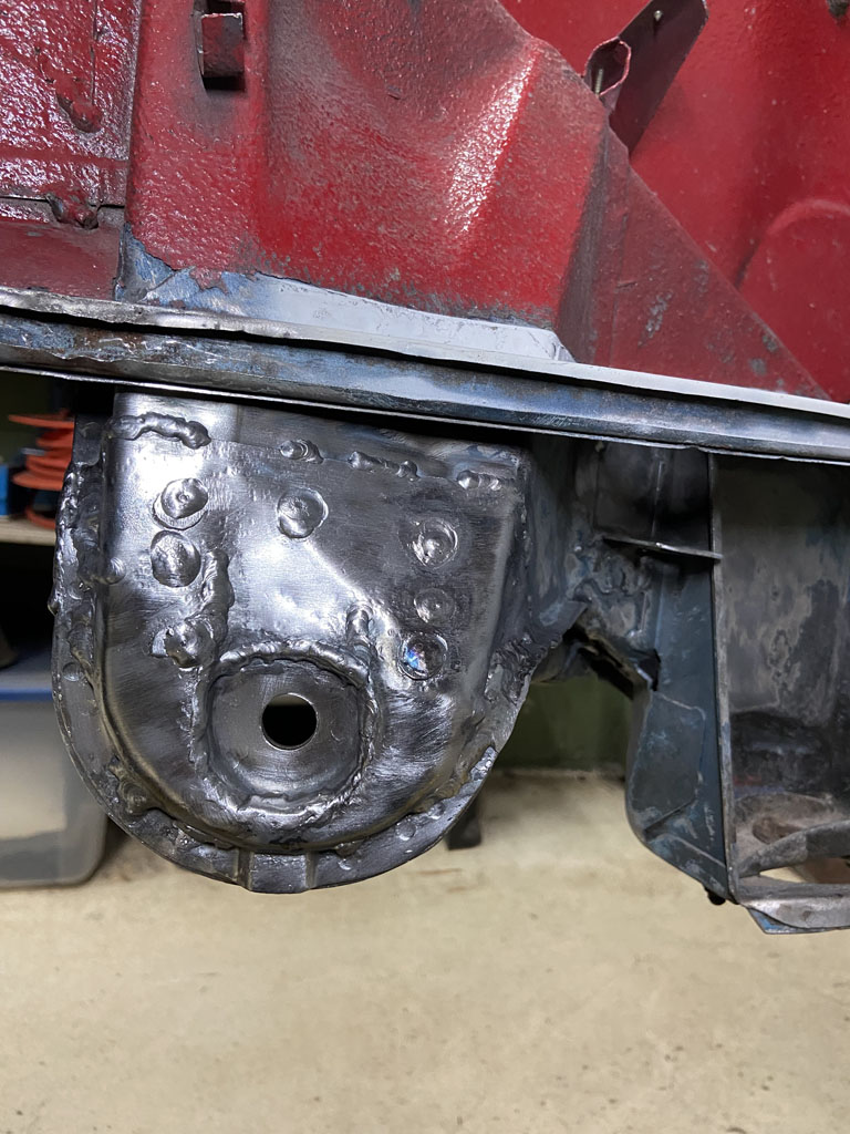
Stripped undercoat and paint off the rest of the driver side suspension console to ensure that there were no other cracks lurking on the driver side supspension console. Good to go! 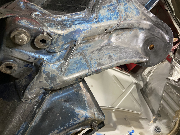
This has been such an odd car to work on. It was Florida car according to previous owner. So much of the metal is in almost pristine shape. Yet, the entire right side longitudinal was completely shot as was the entire floorpan.
Each time I see the wonderful Alaska Blue Metallic paint lurking below undercoating, I can't help but wonder what someone was thinking when they repainted the car red. Someday I'll get around to returning it to Alaska Blue Metallic but that won't be for a long time. Right now priority is to get this back to a rolling chasis.
Next up: Get the right side engine mount and engine shelf installed.
Posted by: Superhawk996 Jan 19 2022, 05:09 PM
Engine Mount Install Underway.
Started by cleaning it up and putting some Eastwood Frame Coating on the backside. 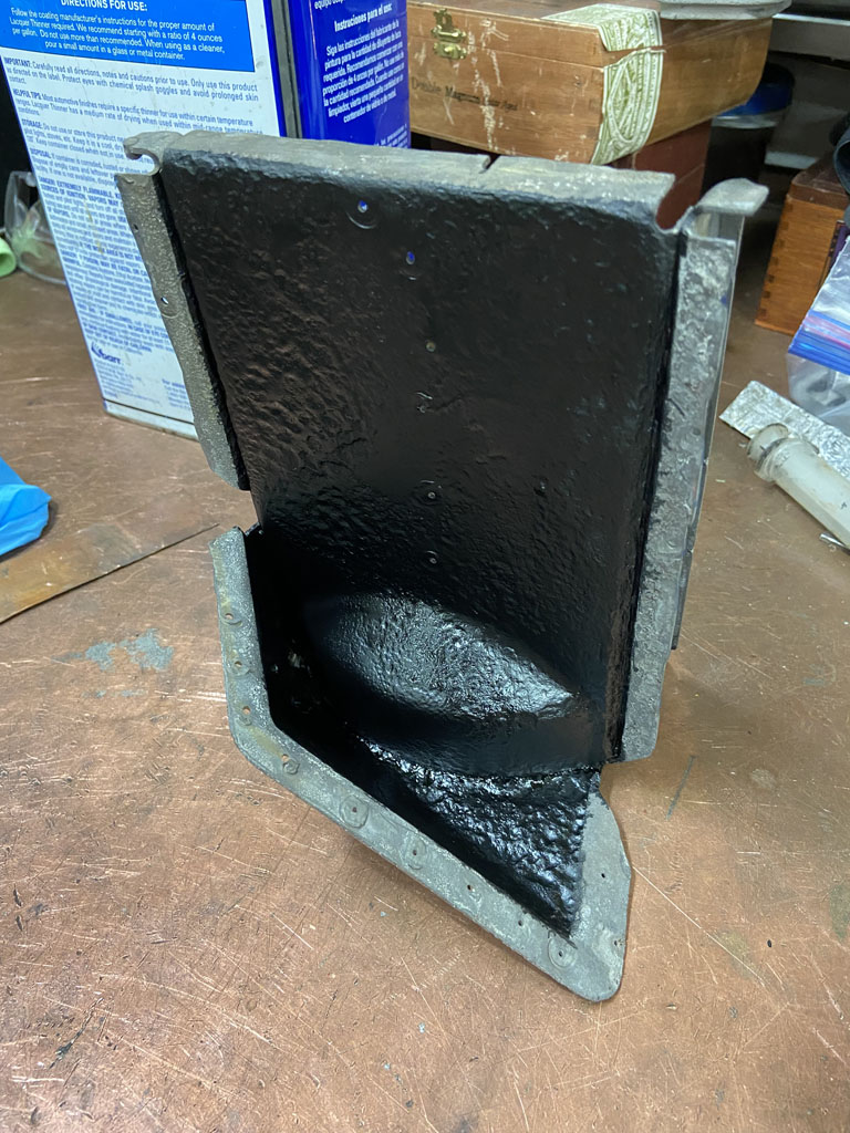
Now I'm a bit surprised no one has called me out on ditching the plan to double wrap that engine compartment longitudinal.
The backstory is that I hate the corrugation on this part. It doesn't reproduce the original at all. Having said that I am grateful that it is available and that I didn't have to fabricate it from scratch. But the corrugation still pisses me off.
I really want the long to look as close to OEM as it can and the corrugations just won't do. In addition, the engineer in me can't stop thinking that lateral stiffness is compromised by the corrugated ribs. Yes, they add overall stiffness to the panel that is far better than flat sheet. Agree completely. The problem is the OEM has the corrugation ribs on the INSIDE and I don't have to look at them. I also think the nature of the 2 piece design with the corrugations on the inside yields a stiffer part since the corrugations are effectively closed off and bridged by the outer panel.
If I wasn't so lazy, I'd do some CAE modeling and figure out if the single piece aftermarket piece (thicker single panel with corrugations) has the same overall stiffness as the OEM parts.
I'd rather be than do CAE on these parts. But couldn't let it go!
To top that off, after developing the templates to do a wrap, I ended up with the cut steel in my hands and decided that was just too much weight to add for what might be too little gain in lateral stiffness.
And as the final straw, when I was mocking up the rear suspension console, it just fit better to the corrugated long without the added thickness of the wrap.
So here's what I did under the suspension console and what I've continued to do under the Engine mount to get a smooth long appearance and to gain a bit of stiffness.
I closed out the corrugations. I used a doubled up 0.043" strip like this. 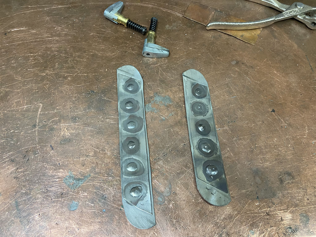
Here it is partially tacked into place and you get the idea of how it rolls over the upper and lower radius to close out the corrugation. 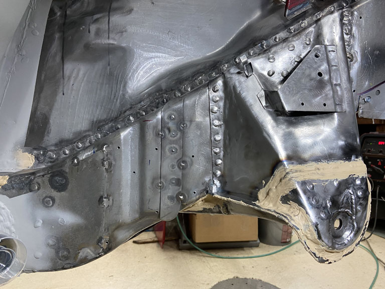
And of course, the weld beads need to be ground down to allow the engine mount to sit flat to the long. 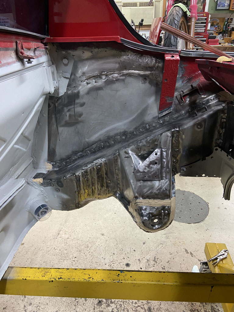
The main downside to this in my opinion is the time spent for an unquanified improvement. Well . . . at least I won't need to look at the corrugations that otherwise would have been apparent above the engine shelf!
With a little luck, I'll get around to actually locating the engine mount and welding it in later this week.
Posted by: Superhawk996 Jan 24 2022, 07:25 AM
Engine Mount Done - Onward to to shelf install.
It's a good thing I don't do this work comercially. I constantly underestimate how much time it is going to take to get to the next step.
Prep of parts is constantly underestimated. I'd be losing my if I were estimating these tasks on a job cost basis.
First the need to get the long coated (and dried) with some Eastwood Frame Coating so that there is some protection behind the engine mount. Then the need to drill the holes in the part for puddle welds. I would normally use a hand punch which is way quicker but the metal on the engine mount is too thick to use the hand punch. 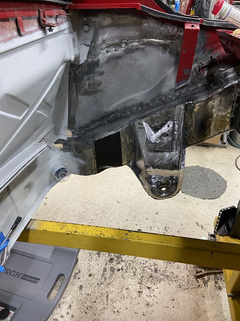
Then to do the basic mock-up work to make sure the part is properly located. In the case of the engine mount, you can't be too far off due to the dimple in the long but there is still a good 6mm of variation both fore and aft where the part could land and still "fit". 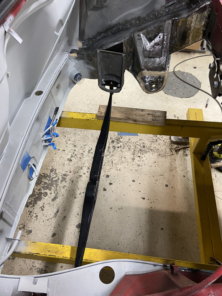
And then finally the welding time.
There are three things here that take forever. First that I'm using TIG. It is a slower process than MIG for sure. Second, the need to keep things cool between welds so that I don't warp anything. Third, all welding is out of position including the puddle welds underneath the long being overhead welds. On this third point, I'm glad I'm not doing MIG which would be a PITA with it's showers of sparks.
Doing this on a rotisserie would certainly be easier, but at this point, it doesn't make sense to stop to build a rotisserie to replace the body dolly that was needed for the the longitudinal and floor pan replacement work.
Win some, lose some. I'm going to call the engine mount being done a win. 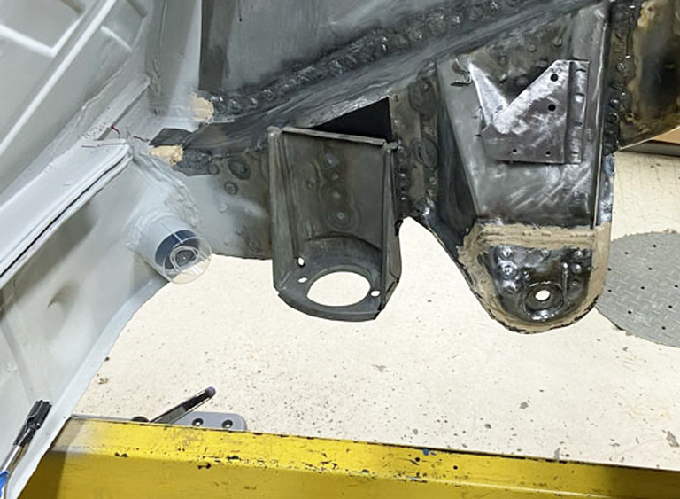
Posted by: Superhawk996 Jan 24 2022, 07:39 AM
Other diversions
As I work toward getting a rolling chassis, I needed some new parts. PMB and 914Rubber to the rescue. 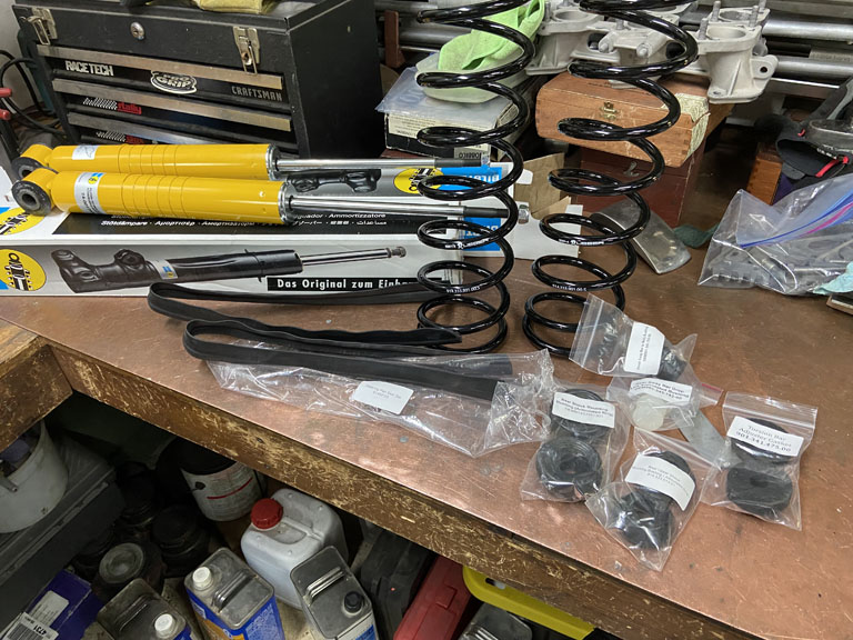
Vehicle came with KYB rear dampers and some sort of progressive spring. Those need to go bye bye. But I needed the spring top caps and associated hardware. 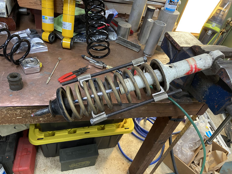
I did get a kick out of the sticker on the Bilstein's that say tested at Nurburgring Nordschleife. I'm not quite convinced these dampers were tested there though I've done some lapping there long ago, maybe someday I'll get the chance to go back if the world comes to its senses. 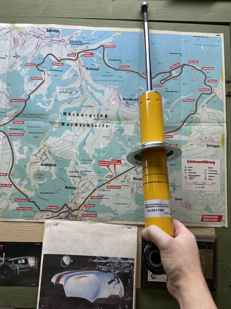
Being a bit OCD, I'm certainly going to have to find some yellow paint to put in that lowest groove so it doesn't rust in the first week it's exposed to the elements. Not sure why Bilstein chooses to put the clip in the lowest grove and then paint. Must be for low riders.
Posted by: Dion Jan 24 2022, 07:54 AM
Brilliant, just brilliant. Phil that is some mighty impressive work going on. I will be taking
some of your measurements into consideration when it comes time for the alignment on my car. You’ve done some homework for sure!
Keep it coming.
Thanks for posting the great details.
Posted by: 930cabman Jan 24 2022, 05:15 PM
Phil, you seem do get an awful lot of great work for being a candidate for OCD? And, where can you possibly find the time for this stuff, btw: keep up the good work and thanks again for documenting
Posted by: Superhawk996 Jan 30 2022, 06:34 PM
Getting Close To A Rolling Chassis:
Engine Shelf is in. Threw down some primer. 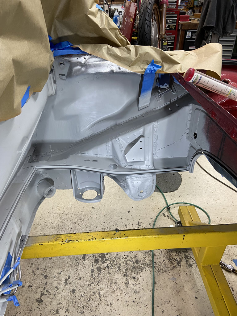
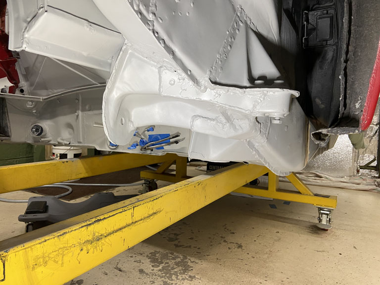
Up next: Time to get those trunk hinges replaced. Also need to bang out a few details like adding the little metal strips for the engine bay wiring harness, and the little lug that holds the parking brake cable. Not big projects but need to get done before I can be done bruising myself in the engine compartment.
Posted by: Superhawk996 Feb 4 2022, 10:07 AM

So tired of thinking that I'll have something knocked out over the weekend, only to find out that isn't likely to happen.
Dug out the new trunk hinge mounts for the body side. Welded in the threaded inserts. No problem there. 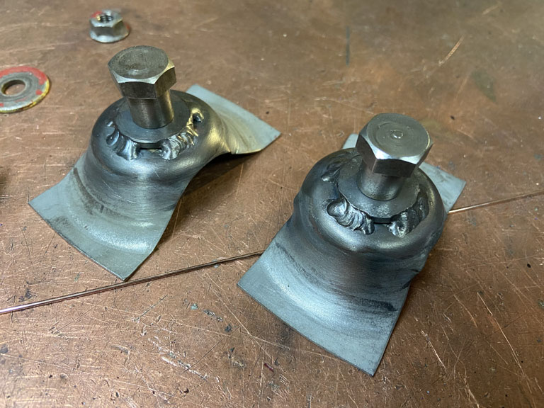
Then I went and dug out the passenger side trunk hinge.
Apparently I have a bad habit of setting aside parts without a good inspection 1st. When I got the hinge back in my hand it was clear that the decades of 1/2 fixes have taken their toll.
When I disassembled it, someone had substituted a threaded bolt and nut for the proper shoulder bolt. Of course the threaded fastener has basically "filed" the hinge bushing. 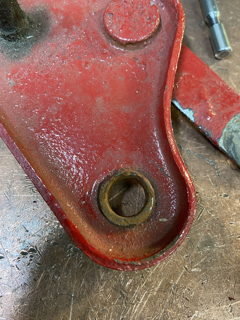
but wait, it gets worse. The other side surface that interfaces with the trunk hinge is corroded, pitted, and worn. That reduces bearing surface and the corroded pits and point loading will quickly wear upon the new hinge bracket. Not acceptable. 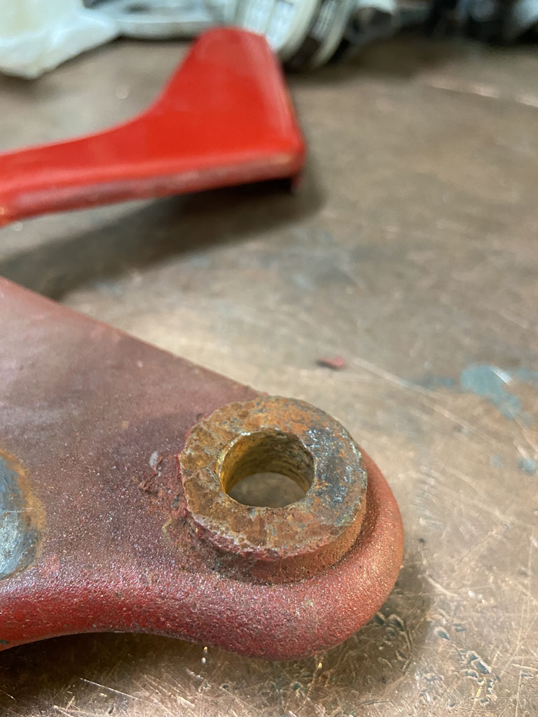
After being thoroughly disgusted with that I cleaned up the little linkage bracket only to discover that it has previously been stripped and 1/2 rethreaded. 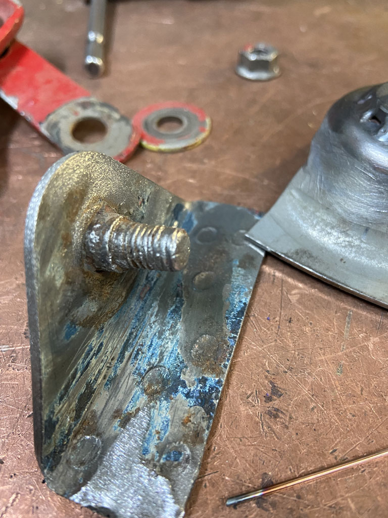
So I guess I'll spend time this weekend turning up new hinge bushing and a new stud.
If anything was working in my favor, I guess it is that I begrudgingly took apart the driver side hinge thinking I might find the same hackery. Thank God, the shoulder bolt is still there and the hinge interface surface appeared to be OK.
I guess the passenger side must have taken the usual battery acid hit which is what lead to the corrosion and subsequent "fixes". Oh, the joy of a 49 year old car. Crap like this makes me wish I had simply bought an Elise.
The frustration will pass . . . I find machining parts relaxes me.
Posted by: 930cabman Feb 4 2022, 06:17 PM
After all, we do this for therapy??? or maybe for relaxation.
Either/or a rolling chassis is a major milestone. Keep it going and thanks as always for posting your progress
Posted by: bbrock Feb 6 2022, 12:58 PM
Holy smokes Phil! I haven't been checking the World lately as life has been hectic, but you have been kicking !!! I found a good match for the Bilstein yellow with Testers enamel paint. When I'm finished with the brake job on my snow plow, I'll pull if off the shelf to get the color. I'm with you though. Those unpainted grooves have GOT to be dealt with
Posted by: Superhawk996 Feb 7 2022, 07:24 AM
Well, turns out I almost got the job done over the weekend. 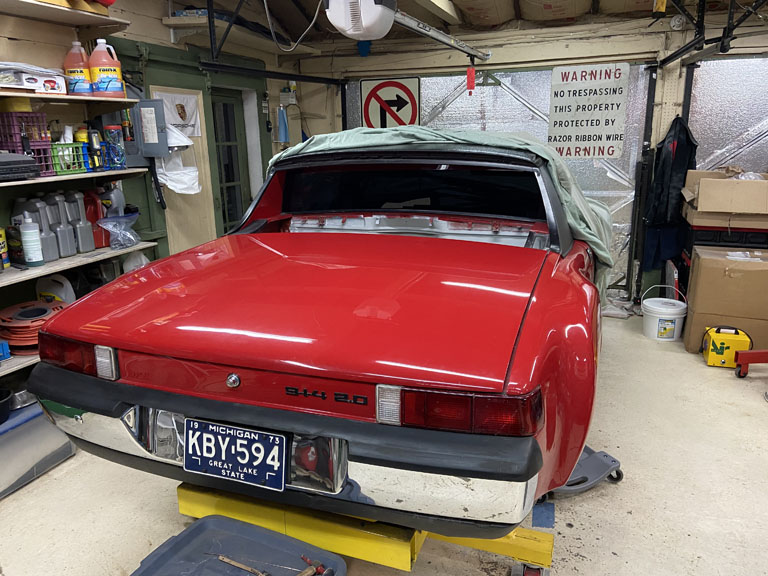
The problem is that the trunk gaps weren't quite where I wanted them and I chickened out on welding the hinges into postion. 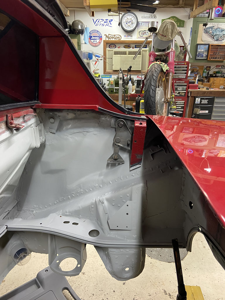
Another problem of too many degrees of freedom:
1) Trunk hinge slots
2) Trunk lock pin variance
3) Fit with seals in or seals out
4) Position of the new hinge bracket vs. the scribed location of the old.
Well . . . the weekend clock ran out before I could work my way through the variables
Here's the fabrication of the new bushings and threaded stud. Used the mill to cut off the off the button head of the old parts. Could also be done with a grinder but would be harder to keep a nice clean level surface for the new part to seat to. 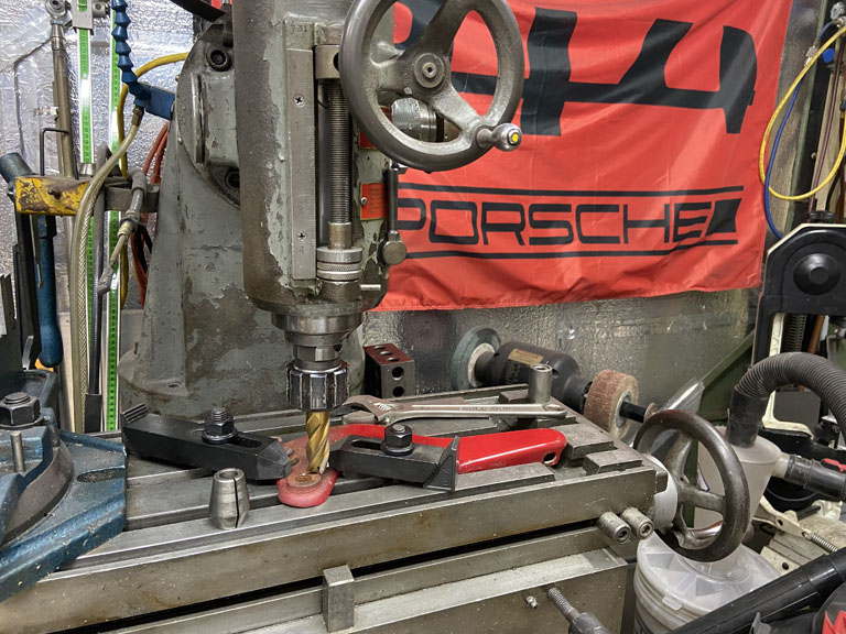
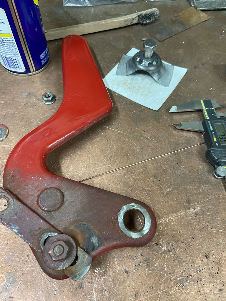
Turned up new parts in the lathe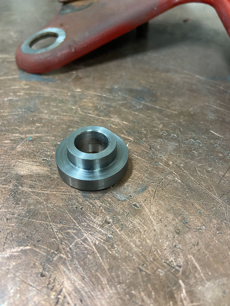
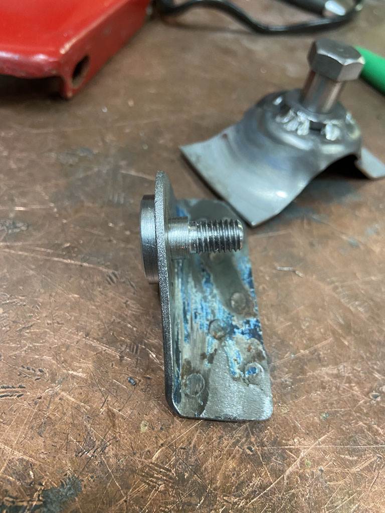
And of course sand blasted and welded the new bushing and stud parts in their new home.
Hope to button it up this week one of these nights after work.
Posted by: tygaboy Feb 7 2022, 09:11 AM
Awesome! When I saw your hinge issue, my first thought was, "No biggie, he'll just buy some replacement hinges... NOT!".
Give a man a dollar and he'll probably just spend it. Give a man a mill and lathe? Well. All sorts of way better stuff happens!
Fab on, my friend. As @http://www.914world.com/bbs2/index.php?showuser=20845 said: You're kickin' it!
Posted by: Superhawk996 Feb 7 2022, 09:41 AM
Awesome! When I saw your hinge issue, my first thought was, "No biggie, he'll just buy some replacement hinges... NOT!".
In all fairness, I did send Oscar a set of hood and trunk hinges for the GT lightening and plating treatement.
This was more about being OCD, not wanting to reuse skanky parts while I wait for something much nicer.
Plus, I have to justify that lathe and mill to the wife
Posted by: worn Feb 17 2022, 02:16 AM
Awesome! When I saw your hinge issue, my first thought was, "No biggie, he'll just buy some replacement hinges... NOT!".
In all fairness, I did send Oscar a set of hood and trunk hinges for the GT lightening and plating treatement.
This was more about being OCD, not wanting to reuse skanky parts while I wait for something much nicer.
Plus, I have to justify that lathe and mill to the wife
Looks to me like road salt could have contributed to the rust fandangos. I have entry level lathe and mill machine tools that have been used to fix household things, and the mig saved a beloved mixing bowl. So my wife has no problem with the tools. The problem is that now i can fix rather than buy. Oh, that is an easy project. Then comes the search through scrap metal hunks, figuring out tooling and clamping. There ensues holding my breath as i get close to final size. A weekend is traded for a little gizmo that i made myself!
Your car looks fantastic. When it is done take it on a ferry ride to Madison.
Posted by: Arno914 Feb 17 2022, 03:32 AM
We all know this very well...lost count over all those weekends fixing stuff...
Posted by: Shivers Feb 17 2022, 08:05 AM
I've been using my drill press as a mill, must be nice to have something that at least looks like a Bridgeport. I think your OCD has served you well, impossible not to be impressed. Great work!
Now I must ask, is it the lighting or is that table top copper? (tell me it's copper... ) I have pieces I clamp in place, sure would be nice to just clamp it to a table for fabrication.
Posted by: Superhawk996 Feb 17 2022, 08:51 AM
I've been using my drill press as a mill, must be nice to have something that at least looks like a Bridgeport. I think your OCD has served you well, impossible not to be impressed. Great work!
Now I must ask, is it the lighting or is that table top copper? (tell me it's copper...
) I have pieces I clamp in place, sure would be nice to just clamp it to a table for fabrication.@http://www.914world.com/bbs2/index.php?showuser=24781
Before I acquired the South Bend Mill for about $0.31/lb, I made do with many years with a X-Y table on a drill press. Works great as long as you're not trying to hog off heavy cuts of metal
I love the South Bend because it's 1950's vintage (I love vintage stuff) and it has positive drive NT30 tooling that I feel has advantages over R8 tapers. Unfortunately NT30 tooling is a little harder to come by, but, not obsolete by any stretch. Yes, part of my workbench top is copper, but, it's copper over wood. I mostly use it for bench welding so I can just lay parts on it or put in the vise and weld away. It's about 1/16" thick roofing copper. If you have some quoted, get it quoted as roofing copper. Oxygen Free Copper is way more expensive. For clamping and welding, I think HF has a cheap steel welding table with clap slots. Of course Miller / Lincoln others have nicer welding tables but $$$.
Posted by: Superhawk996 Feb 17 2022, 08:59 AM
We all know this very well...lost count over all those weekends fixing stuff...
For me, I think those are the best weekends.
I really hate throwing something away when I know it can be fixed. We've become a throw-a-way society. We give a lot of lip service to "green", or "sustainable" energy, houses, cars, etc., but, at the end of the day, nothing is more green than not tossing things into a landfill that can be reused, recycled, or fixed and kept in service.
Posted by: 76-914 Feb 17 2022, 09:37 AM
A weekend (or a weekday) without an accomplishment is wasted. Love those 50's mills and lathes. Wish I had some.
Posted by: Superhawk996 Feb 21 2022, 09:26 AM
Anyone else suffer from having to repair tools before you can do the job you intended to do?
I love these HF rechargeable flashlights. Problem is, like most things, they aren’t very durable. I’ve had these for a couple years but they are getting flaky. Not charging properly and the light flickers from time to time.
Like most modern things, they really aren’t designed to be serviced. The assumption is just throw it away and buy new ones. 
First trick is disassembly. My general thought is that if it was put together, it can be taken apart . . . Somehow.
Here’s the exploded view 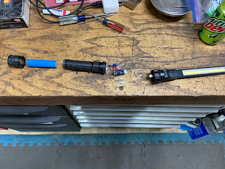
I never know whether to be impressed with miniaturization or pissed off how difficult it makes service. Lots of little surface mount components in these buggers!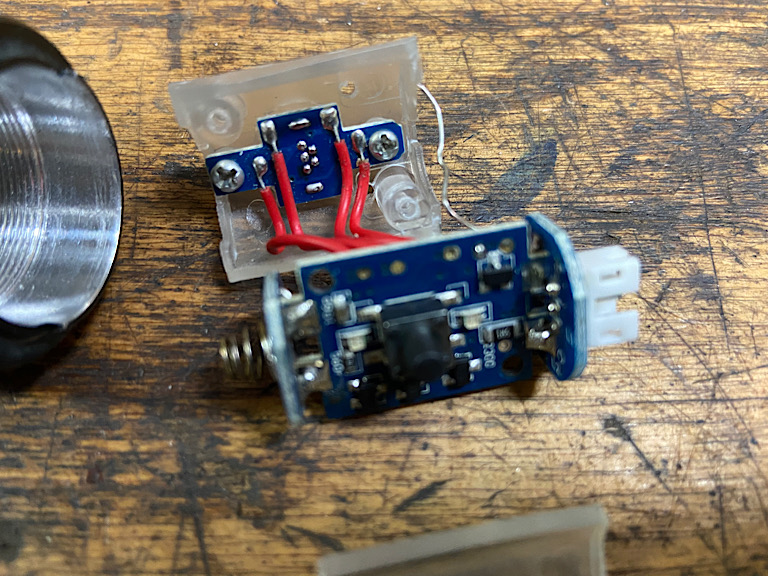
What I found under magnification is that the solder connections to the mini USB were broken from stress cracking as the charging cord is inserted and removed . I can’t even show pics of the repair. I’ll just say if you don’t have a very fine tip soldering iron and experience working with surface mount components, you’re screwed.
The final trick to reassembly was realization that the on/off button needs to be removed from the housing and then reinstalled after the circuit holder is reinstalled. 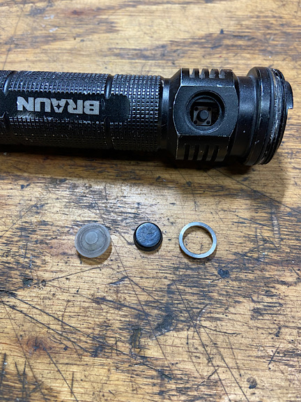
After several hours of work to repair two of these, I’m happy to say they are good as new. At least until they stress crack again. Hopefully not for a couple more years!
Posted by: Superhawk996 Feb 21 2022, 09:35 AM
Here was the original plan. Replace the driver side trunk hinge that had been broken and repaired in the past. The prior repair was a combination of self tapping sheet metal screws and later welding. 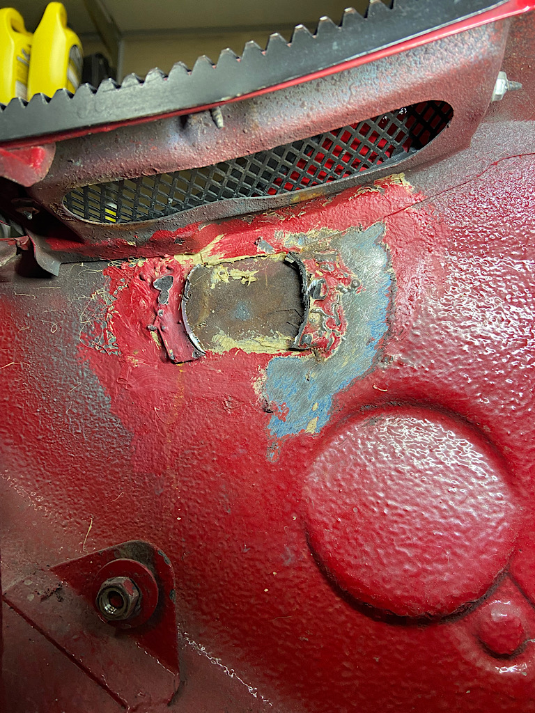
When I finally got it all cut away, there was a small hole where the OEM spot weld tore out. Not a big deal but hole needed to be fixed 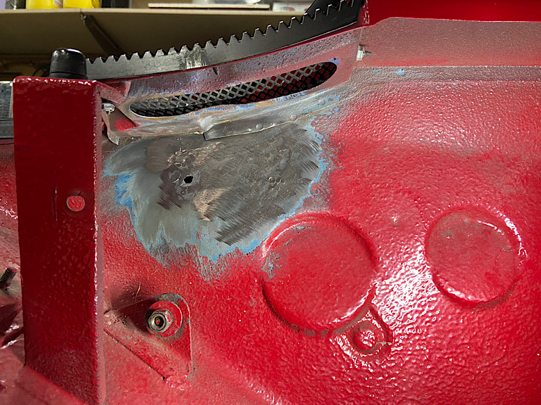
So after the flashlight repairs this is all I got done for the day.
Hopefully I’ll get time to locate and tack the hinge mount this week!
Posted by: 930cabman Feb 21 2022, 04:30 PM
We all know this very well...lost count over all those weekends fixing stuff...
For me, I think those are the best weekends.
I really hate throwing something away when I know it can be fixed. We've become a throw-a-way society. We give a lot of lip service to "green", or "sustainable" energy, houses, cars, etc., but, at the end of the day, nothing is more green than not tossing things into a landfill that can be reused, recycled, or fixed and kept in service.
Exactly, too bad most of us Americans would rather Amazon for anything than repair "some old junk". I always prefer to invest a couple $$ and repair old stuff than spend the long $$ to get some new crap.
Posted by: Superhawk996 Feb 26 2022, 10:29 AM
Engine lid mocked up. Of course the engine lid brackets for this are jacked up. And . . . don't start with me on the painted gold PORSCHE letters I still have the engine lid from my original teener as "wall art". I think I'm going to pull the script off that -- will be cool to have a little of my original 914 in this replacement.
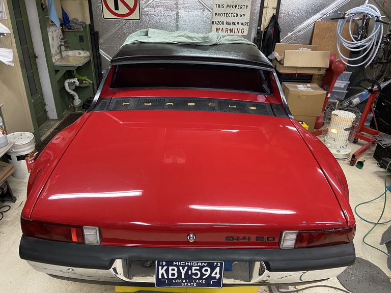
One of the engine lid brackets is broken loose from the firewall and has creative DAPO fix of shooting a bolt though the firewall and was tightened so tightly that it collapsed the formation that the hinge bracket is welded to.
This tips the engine lid mounting bracket to the driver side making the engine lid gaps tight on the driver side, wide on passenger side. Pictures of the as-is condition and final proper fix forthcoming.
Posted by: Superhawk996 Feb 26 2022, 03:18 PM
It's Always Worse Than You Thought
So here's the situation, I knew this part was -ery
Passenger side "fix":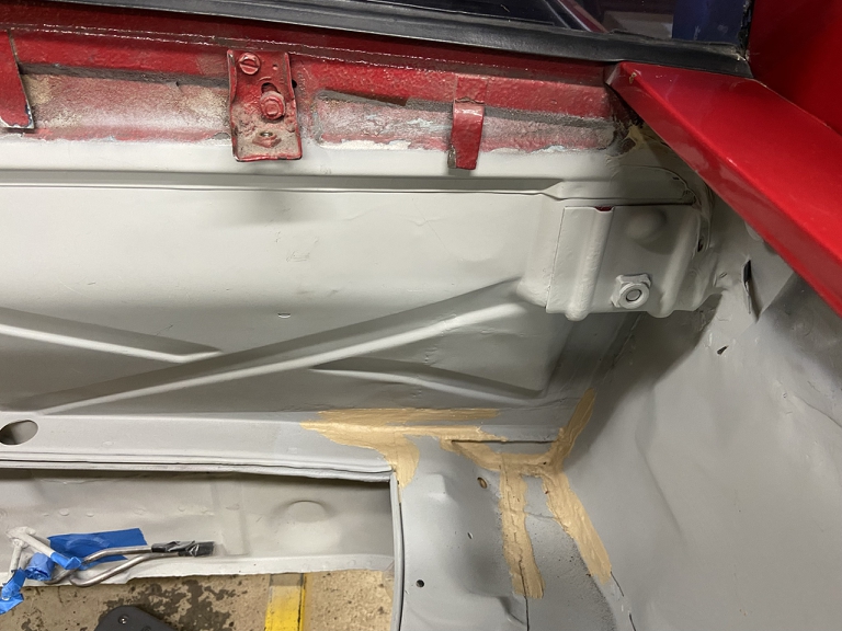
Inside passenger side. Clearly one hole shot and then someone decided to try again. Personally, I really enjoy it when the hardware is SAE rather than metric. It really gives the whole affair an air of I don't give a , let's just get this pile back on the road. It also let's me use some of those SAE tools that don't get much love anymore
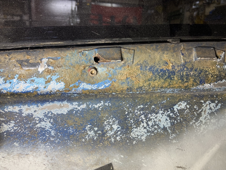
Driver side "fix":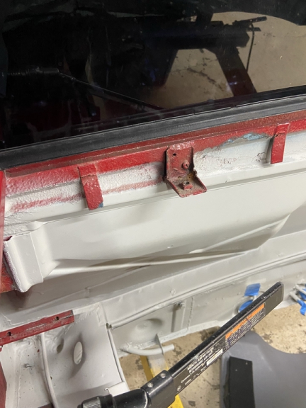
That would be bad enough but it gets worse after removing the brackets.
Passenger side Swiss Cheese. I guess they did shoot more than just two holes I'm betting the 1st "fix" was a couple of sheet metal screws that eventually let loose from letting the lid fly open repeatedly. That is probably what led to the genius idea of shooting a bolt all the way though to the interior. Brilliant! 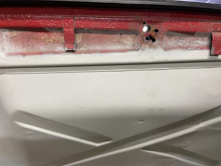
I think you see where this is going . . . wait for it . . .
Driver side: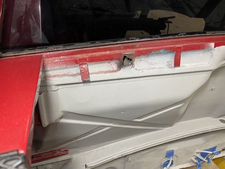
Clearly this had been stress cracked long ago before the red color change where we have a remnant of red overspray on top of rust.
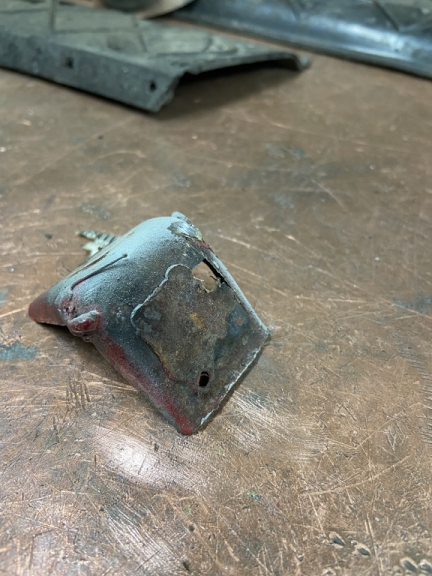
On a positive note, I already have RD brackets on hand to replace these
The driver side came to me pre-stripped but luckily had just enough thread in there after retapping that allowed me to get the lid in there for mock-up and to figure out that the whole lid needs to move 2.5mm to the right. 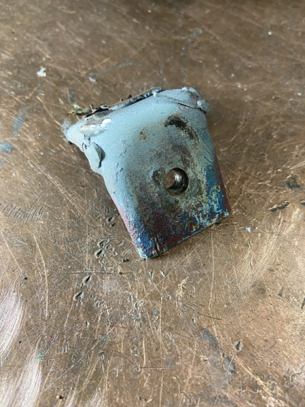
Time to get and
Posted by: Superhawk996 Feb 27 2022, 06:15 PM
Used the old welding rod post trick to get the little hole filler pieces sized and in position for tack welding.
The post allows you to hold the part, keeping it from dropping back in the hole while getting tack welds in place.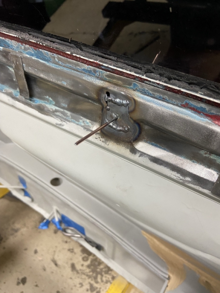
Here's the holes fixed - Driver side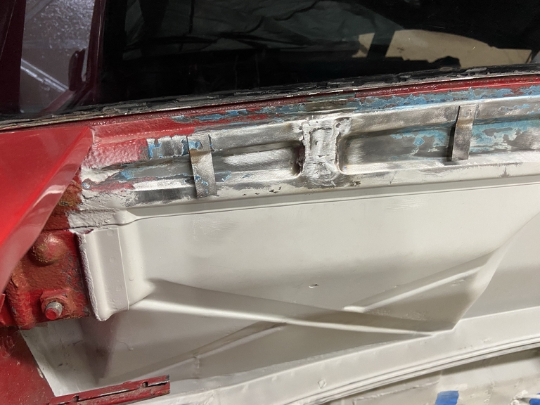
Passenger Side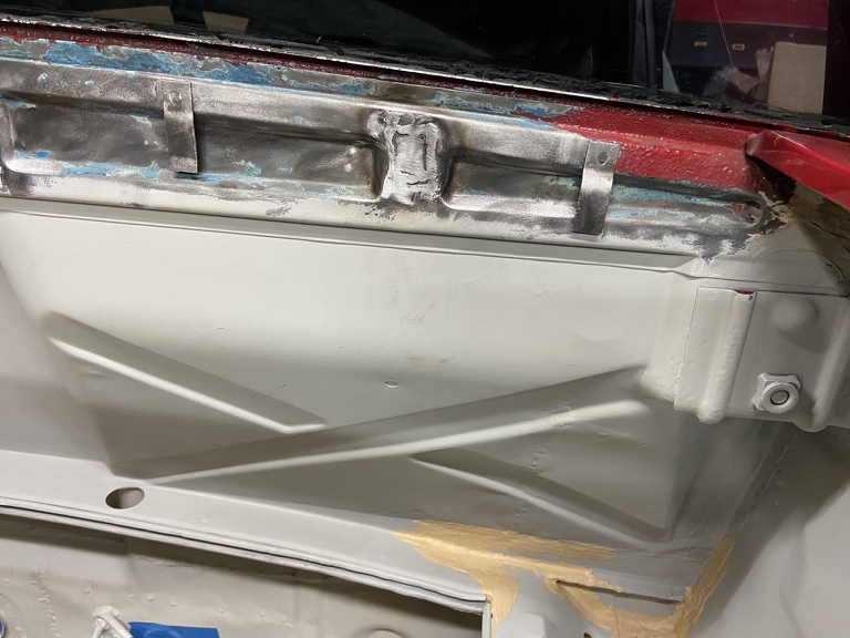
I think I'm going to add a small doubler over these patches. It will move the hinges 1mm further back in space but I think there is enough adjustability in the hinge to accommodate the 1mm of rearward movement. A little extra stiffness in this area wouldn't hurt.
Need to mock up to be sure before I go for it.
Posted by: Superhawk996 Feb 27 2022, 06:29 PM
Side Project Of The Day
Had to make a new set of bushings for a buddy's F2000 Anti Roll Bar (ARB). Thought some folks might be interested in this style of anti-roll bar and how it works.
The actual deflection occurs mostly in the tapered segments. As shown in the photo below the ARB would be at its softest. The closer the links are to vertical the more deflection will occur in the very shot tube between them.
The assembly rides in pillow block bearings supported by the two hex bolts on the ends. 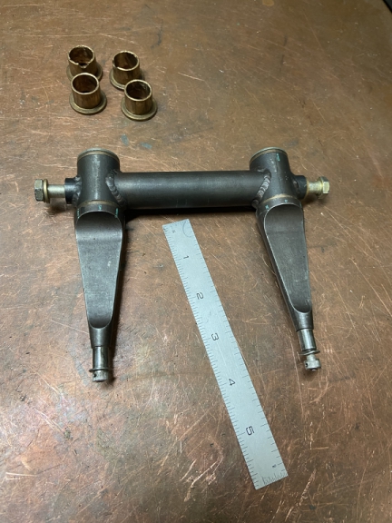
The links can be rotated so that the orientation of the links are either vertical (stiffer) or horizontal (more flexible). or somewhere between as shown below.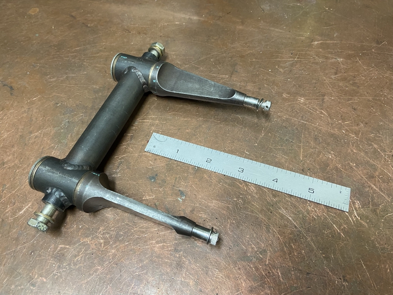
The orientation of the links can be controlled from the cockpit to allow for changes to the ARB rate during the race.
It's very small and compact to fit up in the front area of the chassis where there really isn't much package space.
Pretty cool but not quite applicable to a 914.
Posted by: Superhawk996 Mar 7 2022, 09:47 AM
This past Saturday was Autorama in Detroit. Finally! it was cancelled last two years and is the only thing to look forward to in March.
I always get a chuckle out of the awards for the rat rods. Here's this years survivor award. 
On Sunday I was able to get back to welding and finalized the truck and engine lid hinges.
On the engine lid, I did add a doubler over the original hinge location to reinforce it a bit since this area is prone to stress cracking. 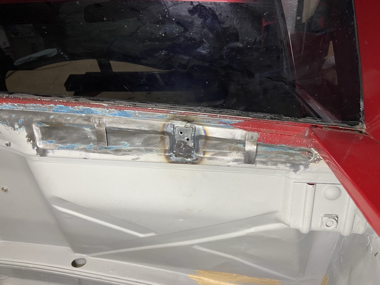
the extra 1mm of thickness caused absolutely no issues.
I'm pretty happy with the gaps given I'm dealing with 1970's quality fit & finish. I moved things around a lot and this is the best I could get. To take gaps & fits to the next level, would involve taking sheetmetal to bare metal and doing weld & grind work along the panel edges. 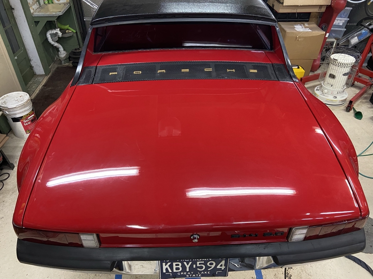
Posted by: rfinegan Mar 7 2022, 10:15 AM
WOW+++ impressive work going on here
Posted by: Shivers Mar 7 2022, 10:27 AM
Used the old welding rod post trick to get the little hole filler pieces sized and in position for tack welding.
The post allows you to hold the part, keeping it from dropping back in the hole while getting tack welds in place.
Good idea. I use a magnet and seam to hit it every time with the welder
Posted by: Superhawk996 Apr 11 2022, 03:08 PM
School of Hard Knocks - Lesson #7461
There hasn't been a lot of exciting stuff to post. Mostly just paint work.
Here's a hard learned lesson during the install of the passenger side door sill.
The rear door gap was being controlled by the loose leading edge of the door jamb panel. Sorry no photo. Depending on where the door jamb was placed, it would deflect the gap either tighter or looser. All though my build I had counted on this flexibility to set the rear door gap.
Well, I had it all set, and had it successfully tack welded in place. All looked great. Again sorry no photos since I wasn't expecting things to go awry at that point.
So as I'm looking at the trough between the sill stamping and the door jamb transition, I thought to myself . . . . . self . . . . you should just use Braze instead of more tack welds. That would minimize the amount of body filler needed to fill and smooth that trough.
Smart huh? 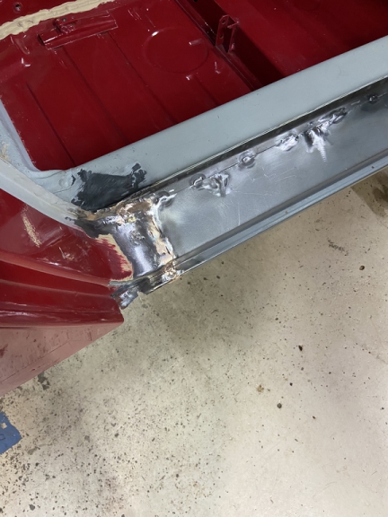
Uh . . . No.
Reinstall door only to find the gap had closed up All sorts of profanity that I hope the neighbors didn't hear. 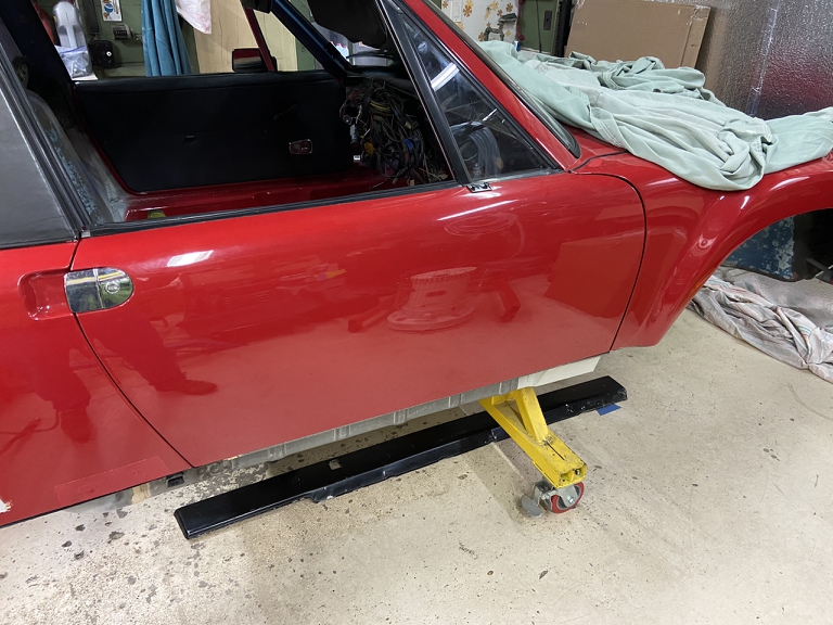
Rear gap closed up.
So what happened?
In order to set the gap, the rear quarter panel was essentially pushed rearward and was under compressive force being held by the tack welds. During the process of brazing, I tried to do too much, too quickly and it softened the steel, allowing the compressive force to buckle the soft steel back to where the panel wanted to be without the internal stress. This closed the gap.
I would have been far better to place a couple more tack welds and to have used the plastic filler that I was trying to minimize. UGH!
So Now What to Do?
I could have fixed this by simply cutting the door jamb, pushing it back to reset the door gap and then re-welding it slowly and carefully. Problem is that I'm now under pressure to get this chassis ready for a cross country trip on the back of a trailer. I am going to be moving soon and this needs to be able to go on a trailer for transport.
Yes, it's a lame excuse for not doing it right. My rationale is that I was eventually going to put steel flares on this car and to return the paint to Alaska Blue since I really do hate red cars. I know how to fix, it. I just need to keep forging ahead due to my move timeline.
So after multiple days of fighting with myself along the lines of "Just fix it right". "No, just get it done". "Yeah, but it would only take a day or two to fix it right". "No! I don't have the time." I finally yielded to the just get it done voice.
Posted by: Superhawk996 Apr 11 2022, 03:18 PM
Paint Progress.
So I've been struggling with paint match. Here are some photos. Original paint code is BMW #138.
When I did the interior, I determined that that code is close but it seems to be a bit darker, deeper red than the exterior and even of the trunk interior which really shouldn't be faded due to UV and the elements.
I painted the upper engine compartment in the same color since I had more of that color on hand.
I then painted the lower engine compartment in Honda R90 which is what PPG recommended as the best color match to a scan we did of the front headlamp cover. I was hoping to get a slightly lighter red.
Nope. 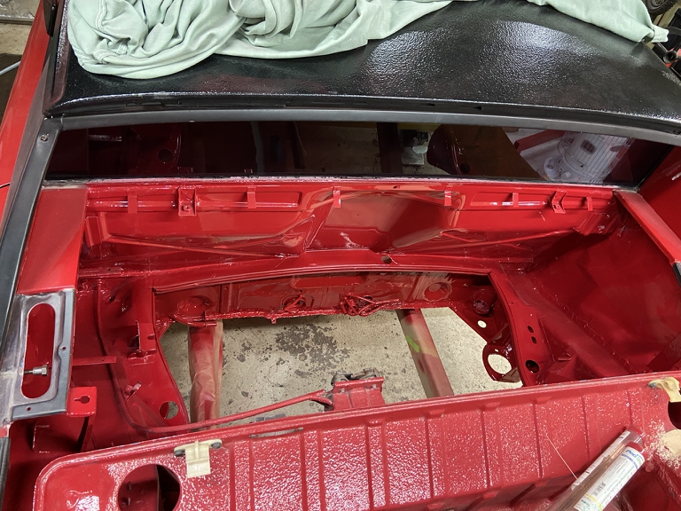
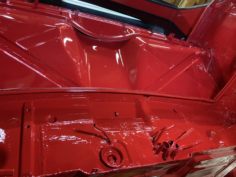
I'm not sure I can even tell the difference.
Then shot the bottom of the floor pan & under the sill. 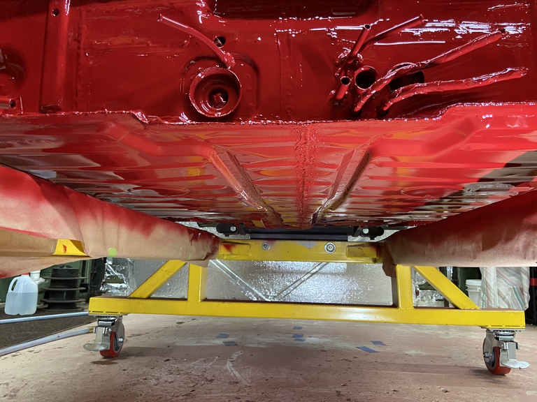
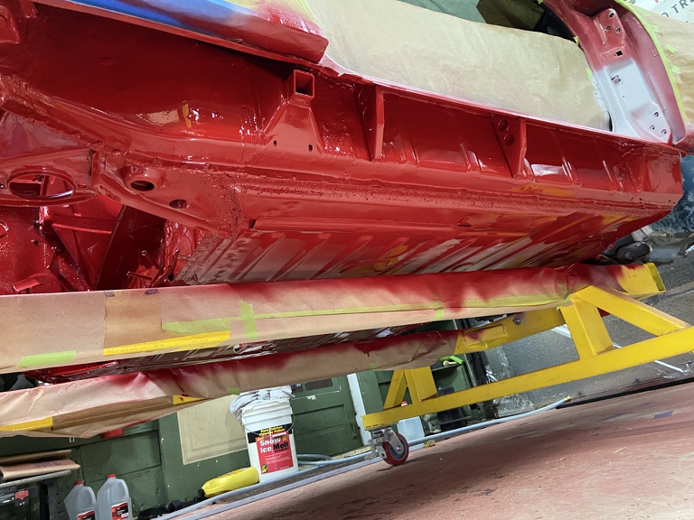
Not having had satisfaction on the engine compartment, I decided to try beige primer on the door jamb and went back to BMW#138
I don't know . . . . I think it's slightly closer but not much - might just be the difference in lighting. 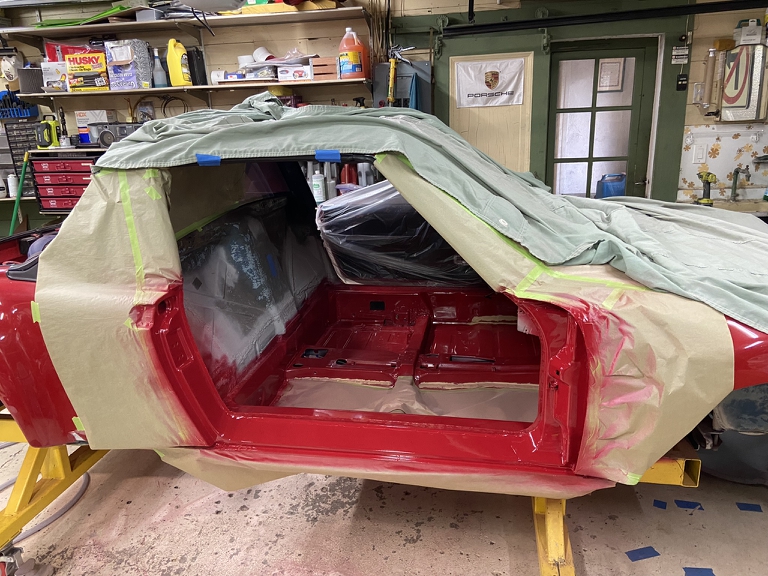
All this leads me to believe I'm going to have a very hard time blending the repairs that need to be made on the passenger side rear quarter later on.
Yup . . . Alaska Blue looking better all the time.
Posted by: 930cabman Apr 12 2022, 04:22 AM
Great progress, but having a cross country move in the program can easily throw a large wrench into things. Good thing she looks like she can be a roller in short time. Also, nice fix with the engine hinge mountings.
Posted by: Superhawk996 Jun 6 2022, 11:11 AM

Per previous posts - still in the midst of putting house on market and getting ready for a big move that will put this project on hold for a while.
Right now the focus is on buttoning up the large holes in the car that would let rain into the car during a cross country open air haul.
Posted by: Superhawk996 Jun 6 2022, 11:21 AM
First order of business has been packing up lots of to get the house in presentable shape for showings.
Apparently potential home buyers have no appreciation for a man cave filled with 914 parts sitting around on the floor.
Part of the packing entails putting the 2.4L 911 engine away for the move. 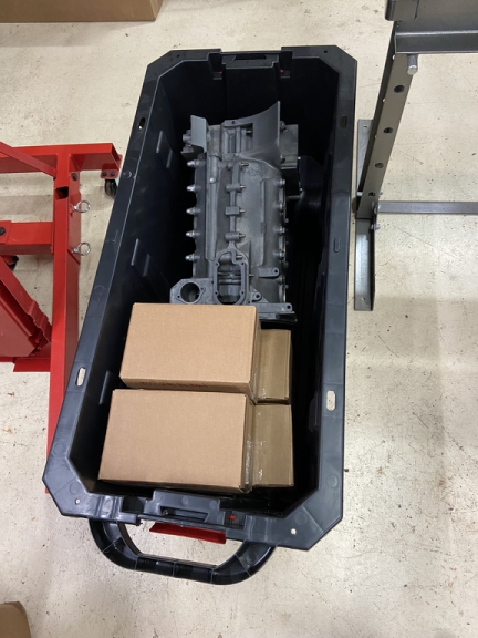
The other task lingering was to seal up the hole in the driver side long where the corroded jacking triangle had been.
Although the driver side long is very sound the jacking point had the usual corrosion that took out the 1st layer of metal that the jack tube welds to.
Here is the finished result - proving that you definitely can replace the jack point tube and pyramid without resorting to cutting the rear quarter panel. 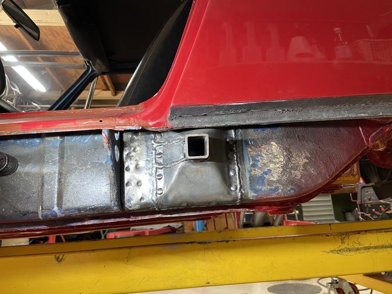
Starts with the usual fabrication of a shallow inverted pyramid arrangement that sort of sinks into the long to mimic the OEM form. 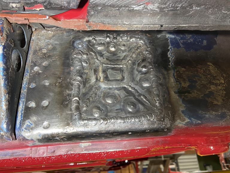
Then location of the tube and welding it to the long. 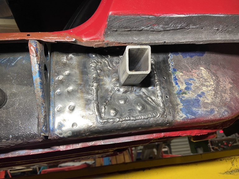
Then the super secret step. How to get the triangle over the post since the rear quarter panel is in the way? 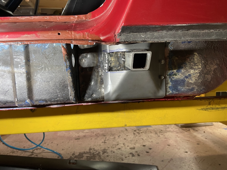
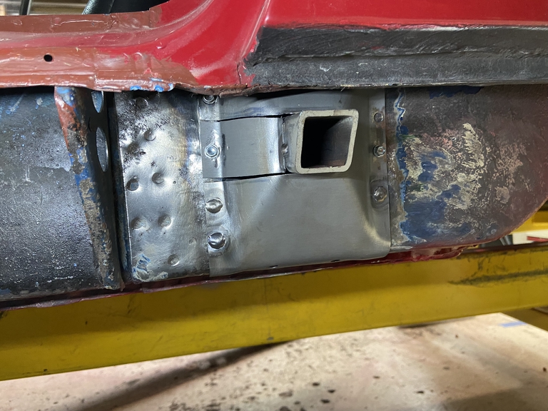
And of course, after that, it's simply a matter of welding it up! Ta da!
Now in all honesty, I was only able to get one lonely spot weld on the top of the triangle up between the inner and outer wheelhouse.
But, the jack point basically operates in double shear with a inward bending load at the top of the jack pyramid. So the attachment at the top of the long really isn't doing anything structural. I would have loved a couple more spot welds up there but it wasn't going to happen.
Final step was seam sealer around the entire triangle perimeter to seal it up and help keep water out.
Note: I still need to drill a couple drain holes on the bottom of the pyramid that isn't in the photos! After those holes are drilled, I'll flood the inside of the pyramid with Eastwood frame coating for future corrosion protection.
Posted by: Superhawk996 Jun 6 2022, 11:54 AM
Now -- time to do my own DAPO workmanship.
What to do about those massive holes created by the AC butchery? 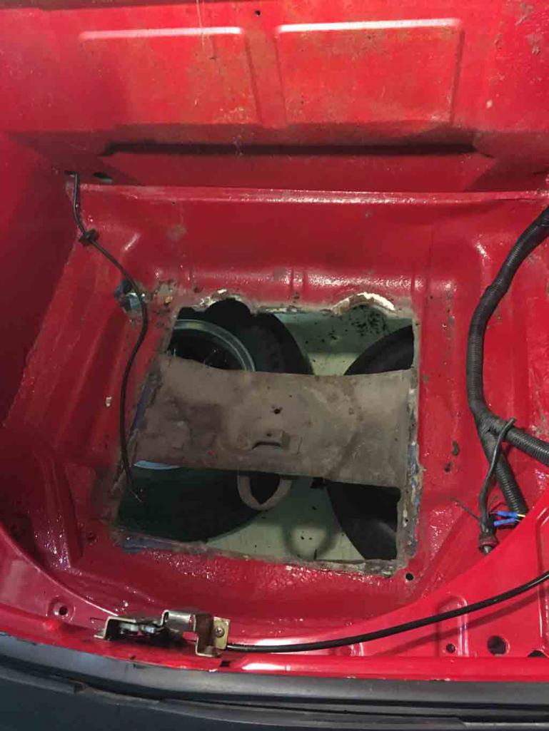
The first thing I have to say about this is for all you guys cutting holes like this for AC and/or water pumper radiator venting is that you don't have enough appreciation for how a unibody structure gets its stiffness.
Cutting holes this large in the Frunk floor pan seriously compromises the structural integrity - especially between the front LCA attachment points that are bearing lateral load.
In the following photos you can see sheet metal that is cracking at the corners that was not part of the the original butchery. This is occurring because the structure is flexing! 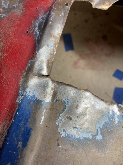
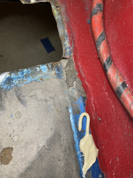
Now let it be said that I have a complete RD front trunk pan that I intend to install at some future point in time.
I just don't have time to do it now with the pending move. This means time for DAPO workmanship just to seal it up.
The short term solution was basically to cut some flat stock, roughly it to shape and then lap weld it in and seal it with seam sealer for the trip - only purpose being to keep water out.
This is my final result (rubber plugs and drain tubes on order for the 4 remaining OEM holes):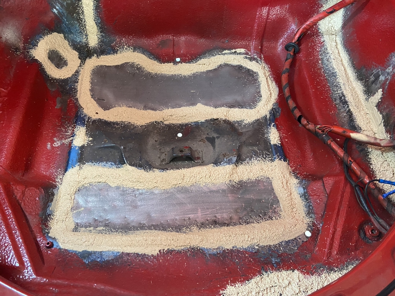
It's hard to convey how much stiffer the structure got after just welding in the first panel.
Along the way, I've had to squat in the Frunk while working on the fuel tank area. I could feel the structure flex unless I stood on the very sides, on top of the reinforcing gussets above the front LCA's. I was very careful to always do this because I could feel the flex.
After welding in these two crude patch panels, I can now stand in the frunk and I don't feel even a hint of flex.
Bottom line, if you're opening up holes like this for conversion cooling, you better be thinking about how you're going to reinforce the structure to gain back the structural rigidity that has been lost.
Posted by: bbrock Jun 6 2022, 09:23 PM
Well you know what? That patch is not half bad. Maybe too good. That's the kind of patch that is so good you can put the "proper" patch off indefinitely.
I would imagine you are quite relieved to have proper stiffness returned.
Posted by: autopro Jun 7 2022, 09:11 AM
I vote Alaska Blue
Great job on getting the chassis strength back up, it always amazes me how some people just think they can start cutting up a car and it will remain as strong as it originally was. Oh and I've had to move with two project cars not finished, it was a total pain in the rear but we got it done. It was actually good because I found parts I had forgot that I had
Posted by: 930cabman Jun 7 2022, 06:06 PM
Great progress, when will she be moving under her own power, after the move I'm sure.
Let me know I have a Carver and Sony maybe we can make a deal
Posted by: Superhawk996 Jun 9 2022, 06:29 AM
Great progress, when will she be moving under her own power, after the move I'm sure.
Unfortunately it won't be for a couple years. First order of business after the move is to put up a shop to work out of -- expect that will take me the better part of a year. After that I'll need to get all my tools set back up (Mill, lathe, welder, parts storage, etc.).
Don't worry, I'll still continue to be a troll on the World though.
Posted by: Superhawk996 Jun 9 2022, 06:49 AM
I'm growing a little uncomfortable at how easily I've adapted to a low standard of workmanship.
Quick paint prep yesterday to get something on work that can't be left exposed to the elements during the move.
I've got to say this looks much more convincing in color. 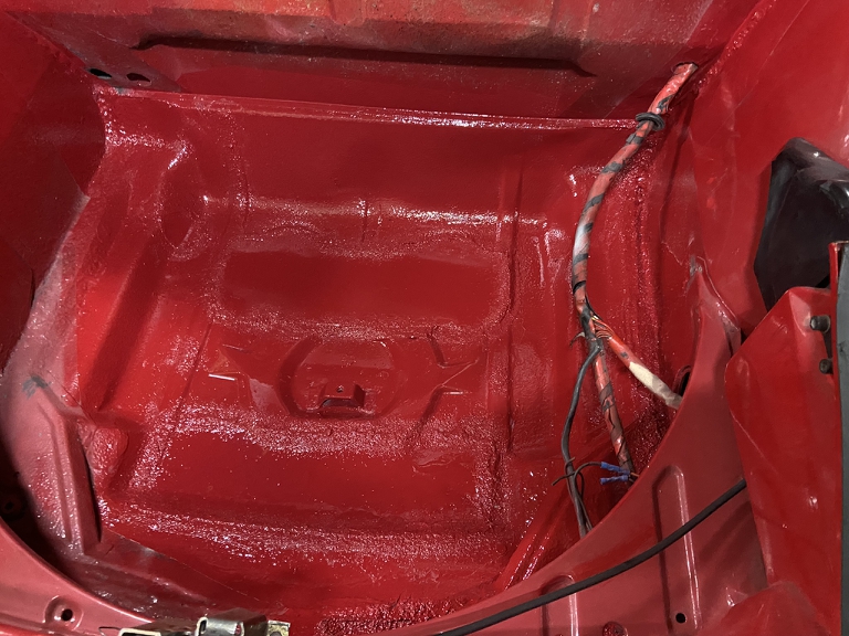
The bottom side got paint to protect the metal but will get undercoated too so that it sort of matches the area under the trunk and the rest of the front that I didn't fully strip. 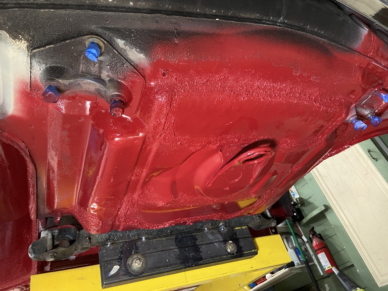
Someday, all this will need to be stripped to bare metal anyway in order to get back to Alaska Blue and to install steel flares.
Here is a quick shot of the driver side front wheelhouse to document that the front was poorly clipped (before me). Someday, this will get redone properly with proper fitting butt welds rather than lap welds as some collision shop did back in the day. 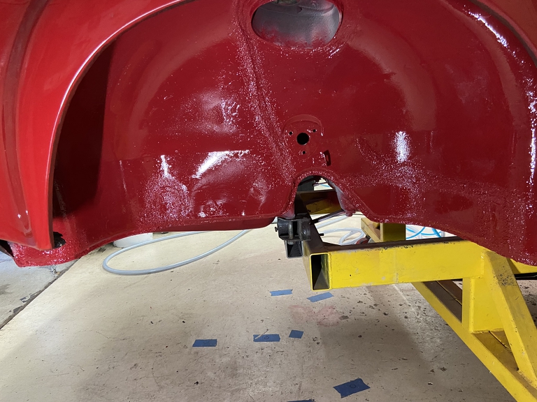
Passenger side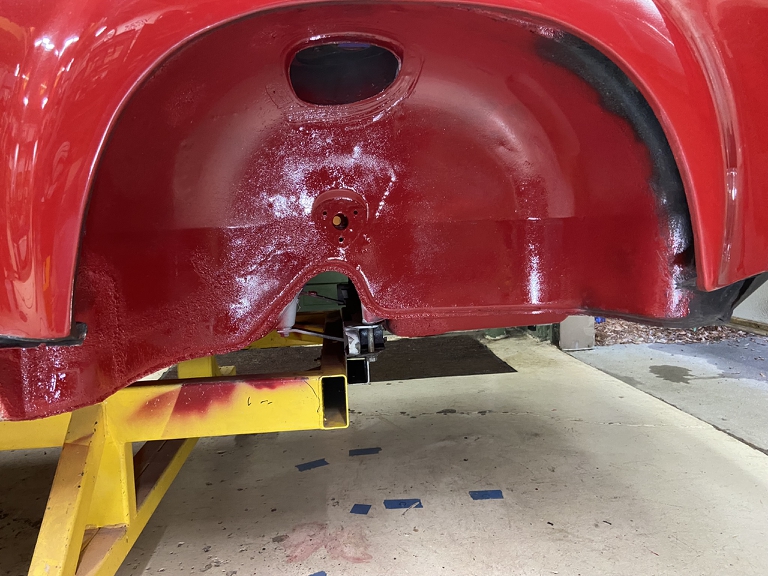
I ordered the whole body seal kit from 914Rubber so I've also been replacing seals to get the interior water tight for the trip.
Front targa seals done and a little bit of a view of the dash panel that was recovered in the proper basket weave vinyl instead of the wanna be MG / Jaguar wood dash that it had when I started. 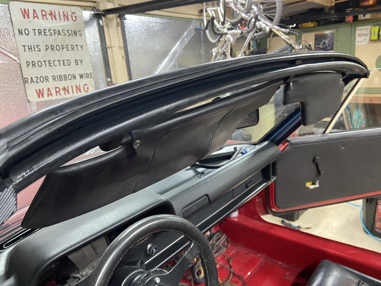
And finally, a really job of putting a little paint on the rear quarter panel damage that I did years ago. It already had dabs of primer but I really wanted to compare the new PPG color match (Honda R90) vs. the other area that I did with BMW #138. I think the R90 is a better match. Obviously this will all need to be sanded, re-filled, etc., and blended for a proper repair. Right now it just needs to keep moisture and rust out.
Unofficial poll:
Which do you think is the better color match? The diagonal swath, or the one on the lower right? 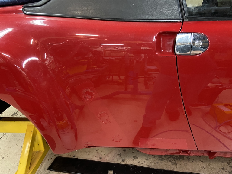
Hoping to have this back on it's suspension and sitting on the ground by the end of the weekend but a Friday graduation party for my buddy's triplets will lay waste to Friday as a full work day.
Posted by: Superhawk996 Jun 9 2022, 06:55 AM
Oh,
And one more photo hoping to convince people to stop cutting holes in these cars that compromises the structure!
Found another stress crack down by the front LCA attachment. When I was laying primer. The contrast between the primer made it stand right out. I had failed to notice this when it was dark paint and/or undercoating under here. 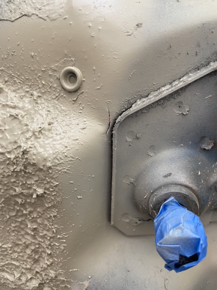
Posted by: 930cabman Jun 9 2022, 05:33 PM
Is this possibly caused due to the missing floor?
Posted by: Superhawk996 Jun 10 2022, 07:24 AM
Is this possibly caused due to the missing floor?
@http://www.914world.com/bbs2/index.php?showuser=24877
Yes, this is a result of the GIANT holes that were cut in the floor of the Frunk for the air conditioning condenser.
Unibody structures like the 914, are able to use thin sheet metal (~0.040") to handle high loads that would otherwise be transmitted into a thick steel frame in body on frame (BOF) construction. BOF construction was pretty much the norm right up though the early 80's for most domestic OEM's. In BOF construction, the body doesn't really bear any structural loads of the chassis. BOF construction is HEAVY! Since the frame bears the bulk of the chassis loads, you can cut lots of holes in a BOF body and have little effect. Not so with unibody construction.
Case in point, my buddy cut the roof of one of our typical 1970's domestic iron BOF winter beater cars when spring came. "Let's make it a convertible".
Sure it flexed a little bit more than it did when it had a roof but due to the thick steel frame underneath, it had very little effect. Don't try that with a unibody! The way a unibody like the 914 gets away with using such thin metal is due to the stiffness that can be created when the sheet metal is formed into geometric shapes like c-channels, box sections (like out longs), or just deep draw formations that stiffen sheet metal panels.
The Frunk has a lot of form pressed into the floor panel to create that stiffness. When the AC holes are cut an enormous amount of that stiffness is lost. The result is that loads are now concentrated, localized and ultimately those loads exceed the limits of the thin sheet metal. That is what leads to this type of cracking.
Posted by: Superhawk996 Jun 10 2022, 10:17 AM
Finishing up paint and undercoating 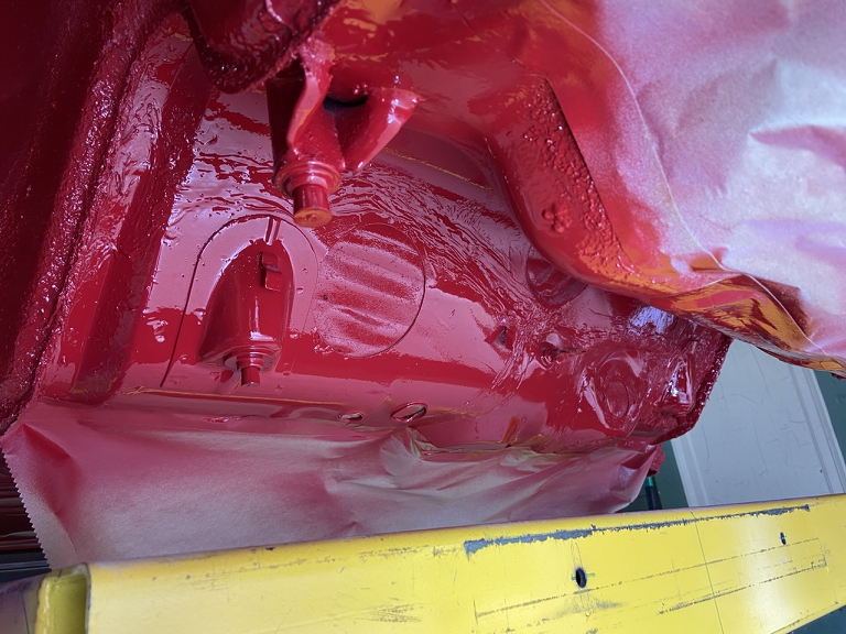
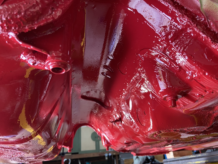
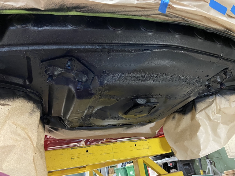
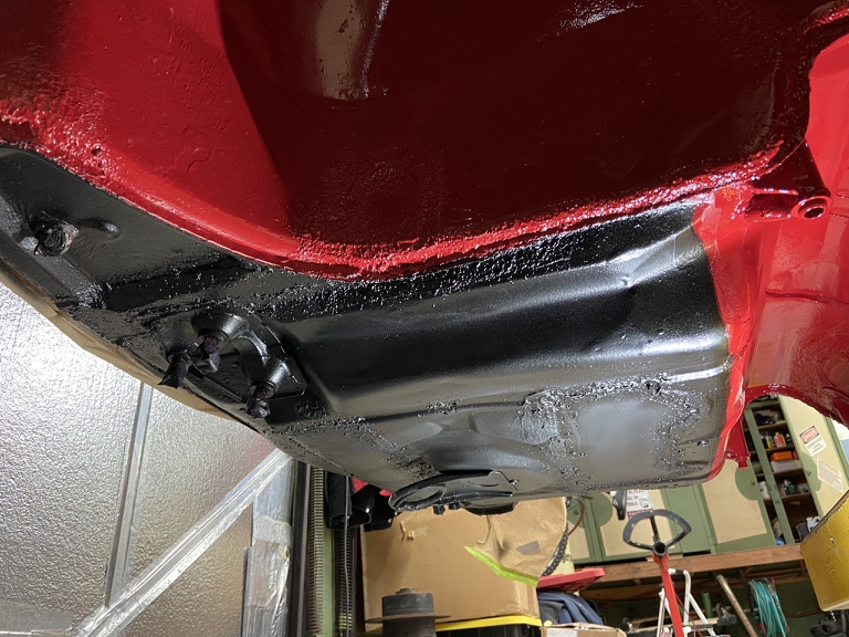
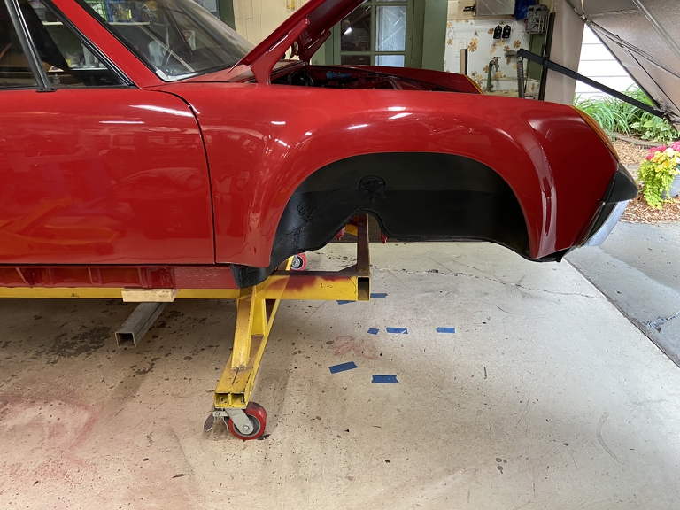
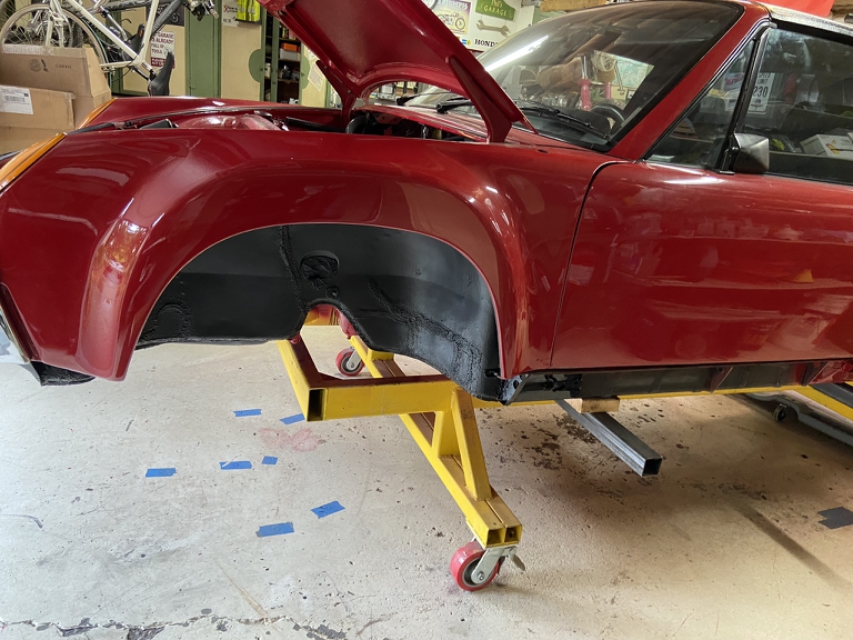
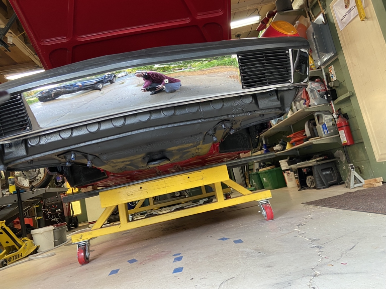
Suspension going on tomorrow.
Posted by: ndfrigi Jun 10 2022, 10:54 AM
wow great work and update with your project! Almost done!
Just wondering also if you are keeping the front wheel well and front trunk under side black?
Posted by: 930cabman Jun 10 2022, 06:58 PM
Suspension going on tomorrow!! a major victory is imminent !!
Also, with regards to the trunk floor being removed and the affect it has on the structure.
My youngest daughter is car shopping and has had Toyota, GM, .... she finally settled on a VW SUV and is all happy. She claims "it's just better", I said it's German engineering.
The krauts still have it, and always have
Posted by: autopro Jun 11 2022, 12:12 PM
You are moving so fast, kicking butt.
Posted by: Superhawk996 Jun 12 2022, 03:44 PM
Just wondering also if you are keeping the front wheel well and front trunk under side black?
@http://www.914world.com/bbs2/index.php?showuser=13474
I prefer body color under there. Problem is the car came to me with undercoating. Since I didn't fully strip the chassis for the rust repair work, I'm forced to try to match what was already there.
Someday chassis will get completely stripped. Then It can be done properly in body color when it goes back to OEM Alaska Blue Metallic.
Posted by: Superhawk996 Jun 12 2022, 03:57 PM
Well, it's officially a rolling chassis. No brakes though -- just good enough to roll onto a trailer. 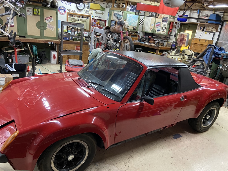
Seems odd to have it sitting so low. I've grown accustomed to safari height with it sitting on the build cart for so many years.
Bittersweet knowing that this is sort of the end of the line for it for a couple years while we get moved. First order of business is to build a shop built so I have a place to finish it.
A few of the pretty bits. Thanks to @http://www.914world.com/bbs2/index.php?showuser=10825 for the plated torsion bar caps!
Front ARB is just there plugging the holes so water doesn't get in there during the transport. 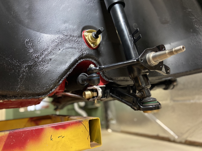
The rear ARB drop links were a bit of a PITA but got those installed so I don't have the rear ARB just swinging around under there while in transport. 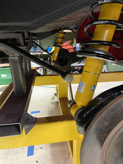
Unlike when the car was 1st transported to me - it now has the axle stubs to prevent the rear bearings from being damaged and/or separating. 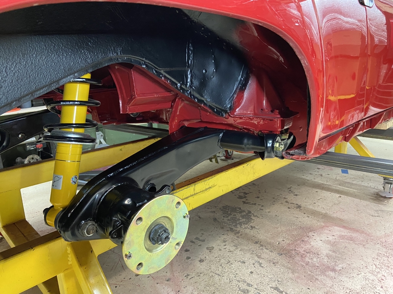
As has been the theme of late, here's another public service announcement.
Make sure you have the right lugs for the wheels you're running.
Here's another case where I didn't pay much attention when I stripped the car down. Wheels are supposed to use Ball Seat lug nuts. Someone was using conical lug nuts. This is a dangerous combination. 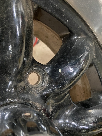
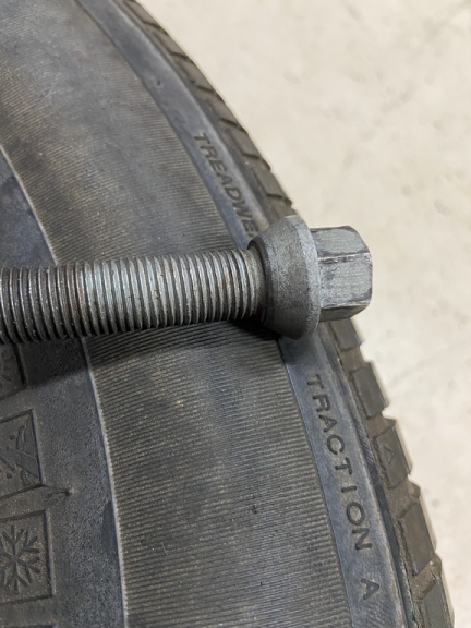
You can see that there is only minor point contact between the wheel lug seats and the conical -- this is a really good way to have wheels come loose on you! Don't do this!
Will work OK for my transport purposes but I'd never drive it like this!
Posted by: 930cabman Jun 13 2022, 06:22 PM
Not under power, but a major milestone just seeing her on wheels must feel great
Posted by: Superhawk996 Jun 14 2022, 07:00 AM
Airbox installed to give rain water a place to go when it inevitably gets rained on during transport. 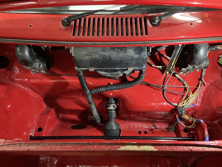
Airbox was updated with new seals from the 914Rubber airbox kit Group Buy last summer.
Here's the super secret rework to get the Bowden cable seal installed. @http://www.914world.com/bbs2/index.php?showuser=3348 Although the seal is a faithful reproduction of the OEM seal dimensionaly, the durometer is harder than my 50 year old seal and wouldn't install properly.
After much futility trying to install it without modification, I had to rework it.
Reshaped the backside to provide some lead in. The removal of some rubber also made it soft enough that it could be deformed and pushed though the hole with some trim sticks . . . and maybe some profanity. I don't know why but the profanity helps. 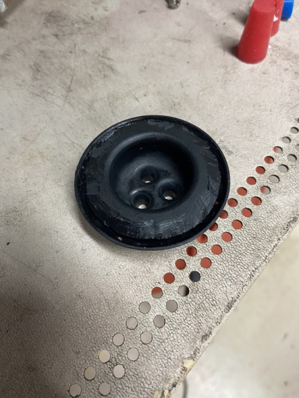
Finally - installed. 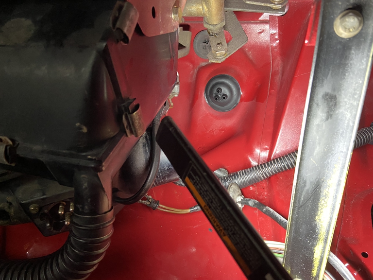
Posted by: bbrock Jun 14 2022, 11:10 AM
Profanity IA like cowbell. You can always use more.
Posted by: Mikey914 Jun 14 2022, 12:12 PM
We fit into a 75 to check this. Looks like there may be some variation.
Sounds like if we go to a softer durometer of rubber it would solve the problem. The current is 75 duro. We could drop to a Shore 60A and that would be more flexible.
Posted by: Superhawk996 Jun 14 2022, 01:44 PM
We fit into a 75 to check this. Looks like there may be some variation.
Sounds like if we go to a softer durometer of rubber it would solve the problem. The current is 75 duro. We could drop to a Shore 60A and that would be more flexible.
@http://www.914world.com/bbs2/index.php?showuser=3348
Remember those types of grommets were installed on a production line, shouldn't take more than a few minutes to get one installed. Having lived a good portion of my life in assembly plants, I can tell you that grommet would stop the line, land an engineer in front of the plant manager, and the ergo committee in about 5 minutes flat.
Huge interrelationship between dimensions, durometer, and shape (form) as I'm sure you already know. All I can say is my 50 year old grommet is softer, and I'd expect that to be significantly age hardened.
That OEM seal design has a ton of meat behind it that has to be compressed a lot to go though the sheet metal You could probably drop down into the low 50's and still be fine. That grommet does nothing but guide 3 Bowden cables (that are already largely self supporting) and help seal the firewall from air / noise infiltration. A move down from 75 durometer would be a huge help.
Good excuse to fund a development fleet. You probably need a 70', a 73', and that 75'!
Thanks for looking into it.
Posted by: Mikey914 Jun 14 2022, 01:50 PM
My biggest concern was that it wouldn't make a good seal. 75 Duro is a typical hardness. The sample I had was in great shape and tested out harder, so we tried to emulate that we had. If there is variation and they very well may be, the softer option should work well. I'll just have to double check it on an earlier car too. Which I now have.
-Mark
Posted by: mb911 Jun 15 2022, 05:46 AM
Phil,
Looks great.. I am happy for you and your move. Someday I may move from Wisconsin to a place more weather friendly for activities year round. Don't be a stranger
Posted by: Dion Jun 15 2022, 06:49 AM
Wow Phil, talk about under pressure. Great job! Car looks great. Ok, a few shortcuts
So what! Good enough for government work. Seriously, nice accomplishment.
Wish you plenty of luck with the move. I hope Mother Nature cooperates.
Can’t imagine the logistics of packing for cross country move.
I’m staying tuned.
Posted by: Jett Jun 15 2022, 08:19 AM
Phil I have a nice enclosed Featherlite that you can use for a few months while you move, but you would need to come get it. Let me know if I can help.
Posted by: Superhawk996 Aug 2 2022, 01:20 PM
Since I just can't seem to get into another day of packing boxes today I'll post a quick update on the 914 project and the move.
The 914 arrived on the other end successfully. 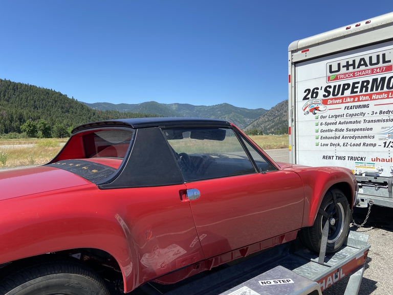
I hope I never have to move again unless it's to a hole 6' in the ground. Moving 2 cars, 5 motorcycles and a garage full of shop equipment has been a logistics challenge.
I did learn a good trick to using U-Haul's. Put down 3/4 plywood as a floor inside the box. That way, you can tie off stuff to the floor. Normally, this isn't possible since U-haul makes no provisions for actually tying stuff down other than their flimsy 3/4" thick wall boards.
Using the plywood floor, a variety of 2x4 blocking, and about 50 ratchet straps, I was able to get everything tied down. Nothing moved or shifted during the 2200 mile trip(s). 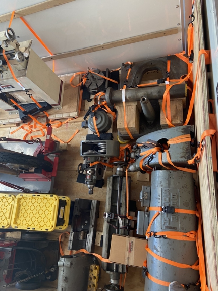
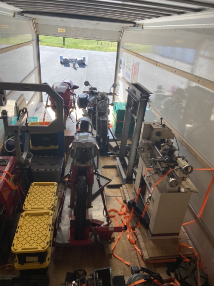
Once the 914 was on the other end, it was put into storage until I can get a garage erected.
The 914 didn't look so bad on the 1st load. 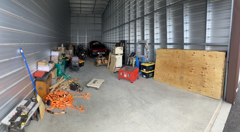
But after the 2nd trip, it's now thoroughly buried. 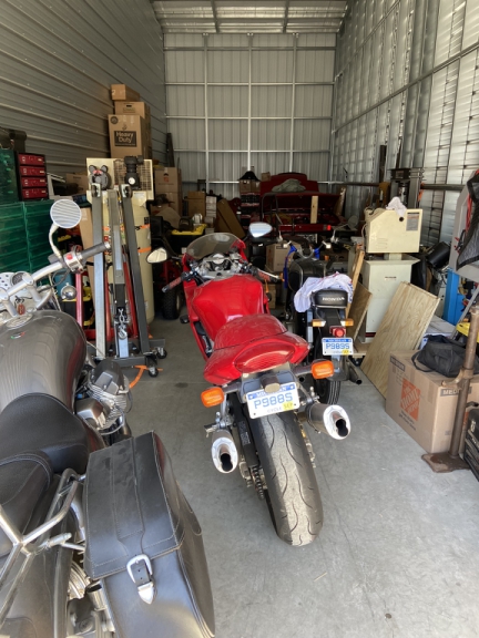
Final pickup of household stuff / furniture is in a couple weeks. Thankfully that will be done by professional movers.
I did leave my engine parts fairly accessible so maybe with a little luck, I might pull off an engine build (in the house) this winter -- don't mention this to my wife just yet ... She won't be totally surprised though. The black motorcycle in the last picture is a 1964 Honda Dream. The engine to that one was built on the kitchen counter of my studio apartment when I was in college.
Posted by: bbrock Aug 2 2022, 04:57 PM
A little heads up so I could buy stock in tie-down straps would have been nice.
Posted by: Superhawk996 Jun 14 2023, 06:16 PM
Status Update. I guess since I can’t post on the 914, I’ll post an occasional update on what is keeping me from working on it.
The short version: I don’t have a garage yet. The 914 still languishing in storage.
The garage foundation is almost complete. Slab pours next week.
The 3’x3’ pads without heating are for hoist placement.
Attached thumbnail(s)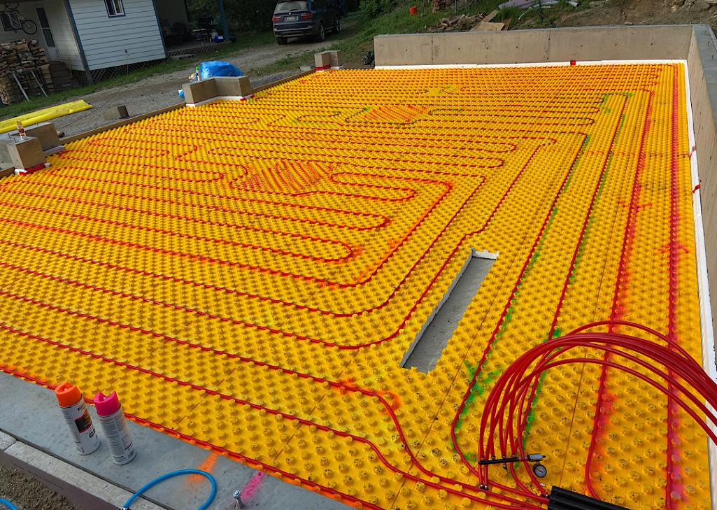
Posted by: jd74914 Jun 16 2023, 12:16 AM
Very cool!! That’s one thing I wish I had done when we did my garage.
Any drawings of what the structure is going to look like? I don’t see any sill anchor bolts, are you drilling those in later or going some other route?
Posted by: ClayPerrine Jun 16 2023, 10:07 AM
Status Update. I guess since I can’t post on the 914, I’ll post an occasional update on what is keeping me from working on it.
The short version: I don’t have a garage yet. The 914 still languishing in storage.
The garage foundation is almost complete. Slab pours next week.
The 3’x3’ pads without heating are for hoist placement.
So you aren't in Idaho anymore? Where did you land?
Posted by: Superhawk996 Jun 16 2023, 12:38 PM
Very cool!! That’s one thing I wish I had done when we did my garage.
Any drawings of what the structure is going to look like? I don’t see any sill anchor bolts, are you drilling those in later or going some other route?
Sill anchor bolts there - look down by the spray paint cans. Just don’t show up very well in the photo.
Structure will look something like this - haven’t entirely decided on exterior finishes.
2nd floor will be some storage and replacement for my finished basement / mancave I lost in the move

Posted by: Superhawk996 Jun 16 2023, 12:44 PM
So you aren't in Idaho anymore? Where did you land?
Exactly the opposite.
Left Detroit, left the auto industry last August. Moved to Idaho not too far from where I lived as a kid in the early 80s. I was in Detroit area for 27 years but if you love cars and wanted to work in the industry, that was where it was at.
Posted by: Superhawk996 Aug 5 2023, 06:09 PM
Framing as a one man crew is painfully slow.
Hoping to finish sheathing in a day or two. Floor trusses sitting on site - putting those up ought to be entertaining. 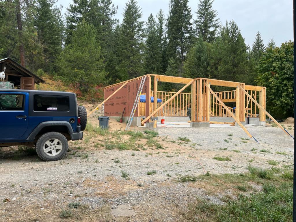
Posted by: Van B Aug 6 2023, 12:04 AM
An entire career of finding the most efficient and effective means to produce something and now look at what has become of you lol!
Are you pushing the nails in by hand too?
Posted by: 930cabman Aug 6 2023, 05:33 AM
An entire career of finding the most efficient and effective means to produce something and now look at what has become of you lol!
Are you pushing the nails in by hand too?
I'm sure it's an adventure, and certainly a day and night from the motor city.
Pushing nails by hand, that's a new one
Posted by: mb911 Aug 6 2023, 05:39 AM
Looks great Phil.
Posted by: Jett Aug 6 2023, 07:53 AM
Looks great!
Posted by: Van B Aug 6 2023, 09:24 AM
An entire career of finding the most efficient and effective means to produce something and now look at what has become of you lol!
Are you pushing the nails in by hand too?
I'm sure it's an adventure, and certainly a day and night from the motor city.
Pushing nails by hand, that's a new one
He’s not responding because he’s probably out harvesting fresh lumber lol!
Posted by: Superhawk996 Aug 6 2023, 10:42 AM
An entire career of finding the most efficient and effective means to produce something and now look at what has become of you lol!
Are you pushing the nails in by hand too?
I'm sure it's an adventure, and certainly a day and night from the motor city.
Pushing nails by hand, that's a new one
He’s not responding because he’s probably out harvesting fresh lumber lol!
You guys are the best.
@“Van B” comments did get me to stop and think about what I’m doing and why. Turns out I’m not after build time efficiency but rather cost savings and the joy (and frustration) of the journey itself. Though I have to admit I would rather be playing in the garage, rather than building the garage. Some days that is sort of a tough pill to swallow.
Labor shortages are a very real thing out here. Builders are going like gang-busters and not terribly interested in a small build like mine without a significant price premium to make it worth their time. The other thing is that my location is off the beaten path and of course that means contractors want even more money. They basically end up paying their crew to commute to my house. So let’s call it 8 hours of pay for the contractor to net 5-6 hours of work from a crew member. At least this was the case with the foundation. I wasn’t about to attempt concrete work myself!
So it turns out that build efficiency isn’t the priority. Capital efficiency is. Was interesting to stop and reconsider if it would be smarter to just pay the labor premium though. I will have to revisit that as fall gets closer to see if I can make a final push and get dry’d in before snow flies.
Posted by: Van B Aug 6 2023, 10:56 AM
Of course you know I’m giving you a hard time for the fun of it.
But on a serious note, when I’ve done construction projects in the past, I would hire someone for a day when I needed some extra muscle. But looks like you’re past those critical phases of the build now!
Posted by: Superhawk996 Aug 6 2023, 11:07 AM
Of course you know I’m giving you a hard time for the fun of it.
But on a serious note, when I’ve done construction projects in the past, I would hire someone for a day when I needed some extra muscle. But looks like you’re past those critical phases of the build now!
I seriously thought it was a funny and valid comment
It did get me thinking which I really appreciate! Most “muscle” is handled mechanically but won’t be an option for the second floor. Luckily the 2nd floor walls will just tip up (wall jacks) instead of having to be lifted 2 feet up onto the foundation.
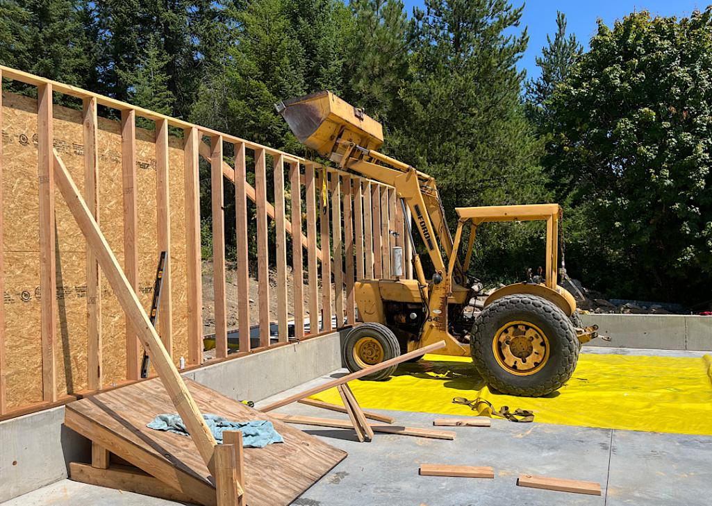
However when I put up the first couple sections of wall, the neighbors tractor was broken (leaking radiator and leaking power steering). So I had to get a little more creative with ramps, block and tackle, and the Jeep winch.
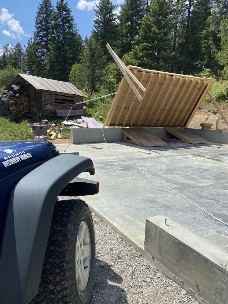
Those early stages when the tractor was broken, before I fixed that issue, really slowed me down in late June - early July.
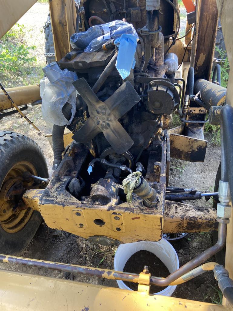
That’s my story and I’m sticking to it.
Posted by: Van B Aug 6 2023, 05:41 PM
Neighbor loaned you his busted tractor eh?
Neighbor: Hon, that engineer wants to borrow my tractor.
Wife: Your yellow one? I thought it was broken?
Neighbor: Did you hear the part where I said engineer?
Wife: Ohhhh.
Posted by: jd74914 Aug 7 2023, 08:28 AM
Posted by: 930cabman Aug 7 2023, 09:00 AM
Neighbor loaned you his busted tractor eh?
Neighbor: Hon, that engineer wants to borrow my tractor.
Wife: Your yellow one? I thought it was broken?
Neighbor: Did you hear the part where I said engineer?
Wife: Ohhhh.
Maybe we shouldn't laugh, it may be the case
Posted by: Superhawk996 Aug 7 2023, 12:40 PM
Neighbor loaned you his busted tractor eh?
Neighbor: Hon, that engineer wants to borrow my tractor.
Wife: Your yellow one? I thought it was broken?
Neighbor: Did you hear the part where I said engineer?
Wife: Ohhhh.
Maybe we shouldn't laugh, it may be the case
Pretty much nailed it.
However, I’ve been borrowing it occasionally since 2008 so it’s not like they waited for me to use it and break it. I’m just fortunate to having had them be so willing to loan it to me for last 15 years. A little maintenance is a small price to pay.
More like it’s been used and abused hard for 40+ years and just needs TLC to keep going for the next 10 or more years.
But there is a little SUV in the garage that the sons took the whole I/P out in the process of fixing an heater core leak. Now the kids can’t remember how they took it apart. They are looking for some help with that one that I’ve been putting off. They did seem a little too excited to have us move onto the hill permanently.
Posted by: Superhawk996 Aug 7 2023, 12:45 PM
That’s a favorite clip of mine.
Pretty much a summary of my childhood. When I was about 6 years old my parents gave me one of those old style store cash registers (1930s vintage) that was already broken. Man, did I have a field day taking that thing apart!
Happier than a bird with a French Fry.
Posted by: jd74914 Aug 8 2023, 08:30 AM
That’s a favorite clip of mine.
Pretty much a summary of my childhood. When I was about 6 years old my parents gave me one of those old style store cash registers (1930s vintage) that was already broken. Man, did I have a field day taking that thing apart!
Happier than a bird with a French Fry.I figured so much!
I started engineering school a bit after that show aired and thought it hit a little close to home too. And now I see the same thing with my 3 year old...he spent hours the other day taking apart two dead bolts. Tough when his mom is an engineer too.
Posted by: Superhawk996 Aug 8 2023, 03:09 PM
And now I see the same thing with my 3 year old...he spent hours the other day taking apart two dead bolts. Tough when his mom is an engineer too.
Sweet - give him some 914 lock cylinders next. See if he can re-key all your locks to the same key assuming your car is like most with mixed key sets
@http://www.914world.com/bbs2/index.php?showuser=1659
Posted by: jd74914 Aug 8 2023, 08:41 PM
And now I see the same thing with my 3 year old...he spent hours the other day taking apart two dead bolts. Tough when his mom is an engineer too.
Sweet - give him some 914 lock cylinders next. See if he can re-key all your locks to the same key assuming your car is like most with mixed key sets
That's a great idea. Probably keep him busy all weekend with a little file set.Now his 20 month old brother is more into machinery...kid can barely talk and still corrects people when they mix up skid steers and compact track loaders or other machine pairs. So proud! Bugs the shit out of my in-laws getting corrected by a toddler all the time.
Posted by: Superhawk996 Oct 17 2023, 07:56 AM
Sort of in a funk today. The news yesterday of Brent’s passing is weighing on me. I hadn’t heard from him since September and feared the worst - only to have it confirmed.
I had barely been on this forum but for more than a few months and was struck by Brent’s thread. I really appreciated his fortitude taking on the restoration of a chassis that almost anyone else would have scrapped. More than anything I appreciated his can do attitude and knack for fixing parts rather than simply writing a check. Only a short time later Brent invited an internet whacko to visit him and see his project in person. His generosity with his time, experiences, and even a few parts never ceased to amaze.
Visiting Brent’s project 2019: 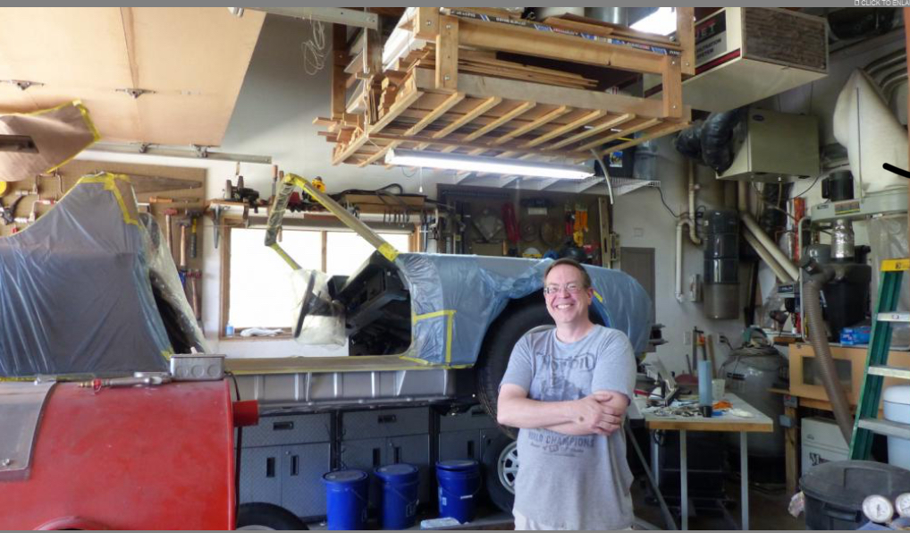
One of the last texts I had from him was that he was driving the 914 to some appointments. I’m so glad he was able to finish his project and was having a good time enjoying it.
When I was in the process of finally moving to Idaho in 2022, Brent convinced me to drive his car after some initial reluctance on my part. What an amazing experience to drive something that had been brought back from what had been a rusted hulk riddled with weasel urine! His generosity in sharing that driving experience is a memory I’ll always treasure.
Simply not enough people like Brent in this world.
Posted by: Superhawk996 Oct 17 2023, 08:15 AM
A few people know that Brent had wanted to build a bigger garage - don’t we all! He was a consultant of sorts to my garage build.
Brent had experience with the radiant floor heat install in his house and had created a really novel control strategy for his mod-con boiler. It was a real benefit to me to have been able to get his input before I did my radiant floor install.
Similarly Brent had some amazing wood working talent which was never really highlighted on this forum if only because of the subject matter here. Some of the cabinets he made from reclaimed lumber and architectural touches in his home were beautiful, amazing, and an inspiration to me.
As I continue to work on my current garage project, it will always be reminded of him and hopefully inspired to achieve the level of detail that Brent brought to all his projects!
Latest status of my garage build - looks like I’ll be working well into the winter. 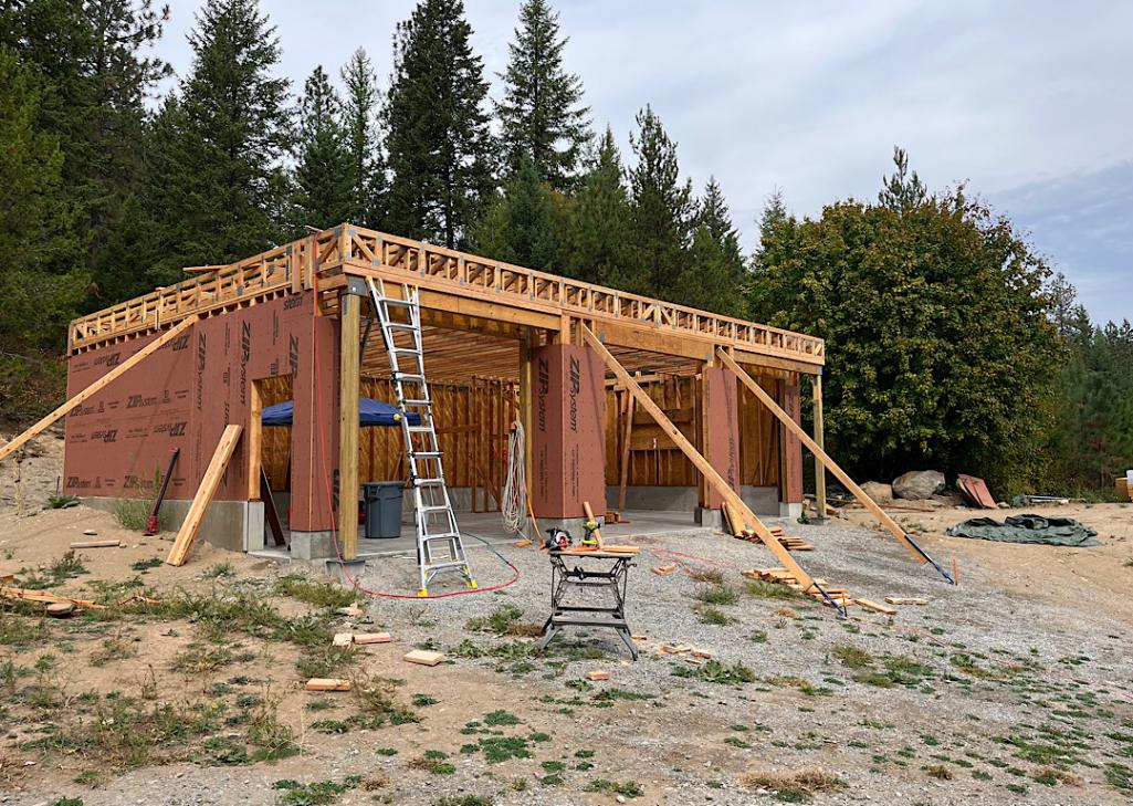
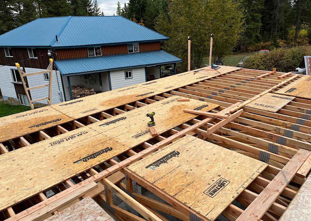
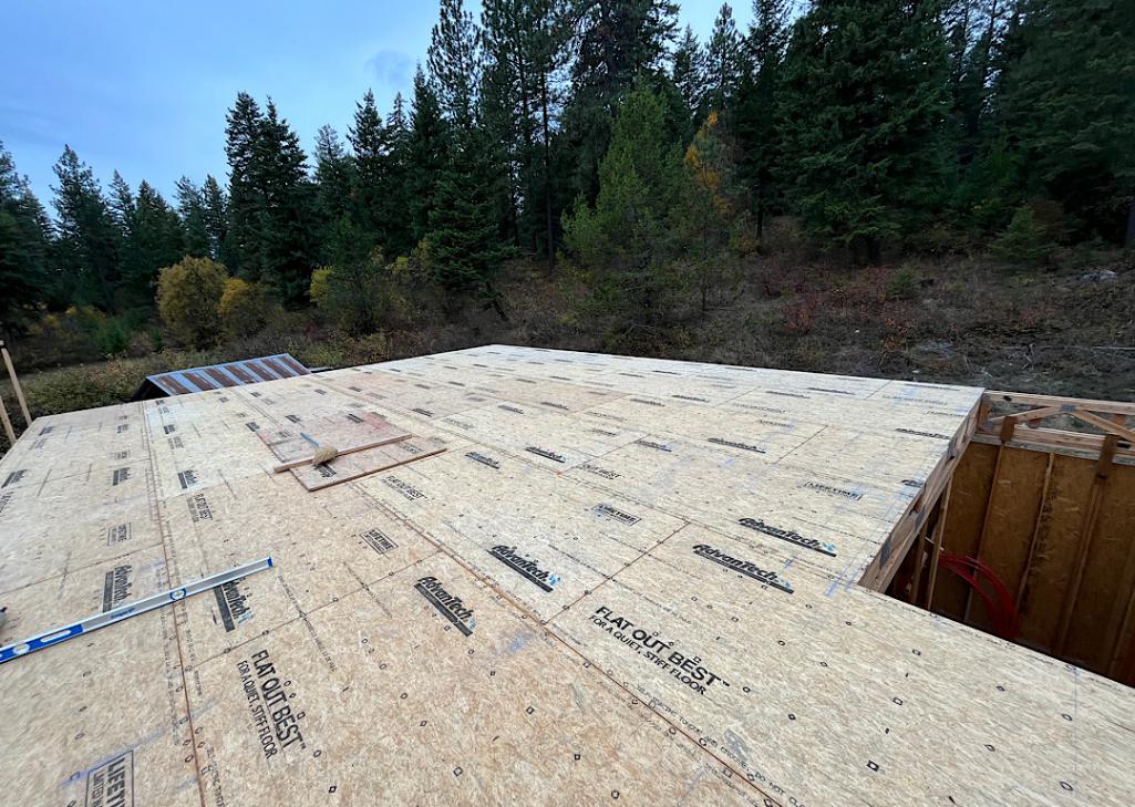
Posted by: Superhawk996 Dec 9 2023, 07:44 PM
Roof trusses arrived 11/14 after much debate about whether they would be able to be built and delivered on site before snow would make it impossible to get them delivered.
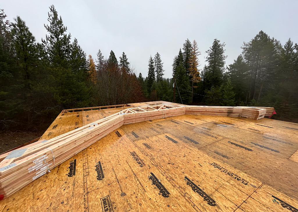
Snow arrived December 2nd.
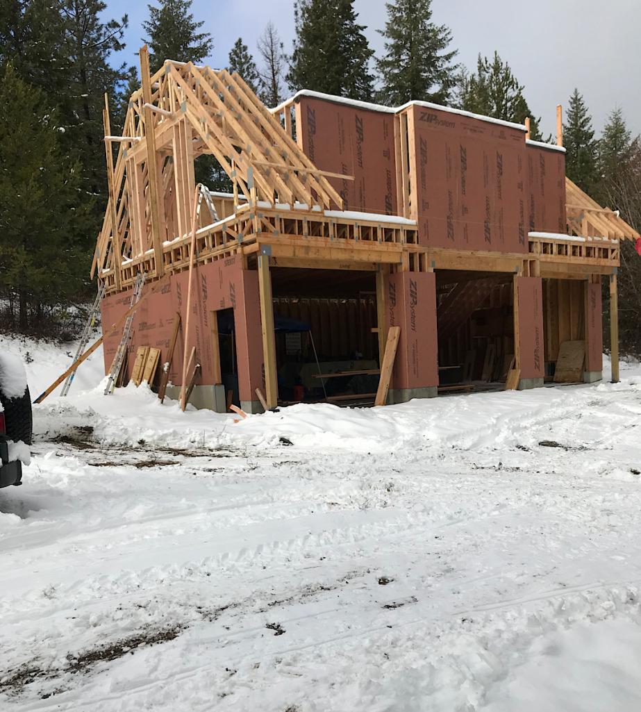
Things about to get much tougher as weather cools. Hoping to get center section roof trusses up before Christmas - we’ll see.
Going to be a while longer before I can start working on the 914 in here
Posted by: flyer86d Dec 10 2023, 04:52 AM
That’s a nice garage project! Be safe roofing in the winter. Reconstructing our house has cost me 18 months of not being able to work on my Porsche projects until this past week. The 68 911 is just about done except for minor details so I decided the winter project will be assembling the motor for the -6.
Charlie
Posted by: mepstein Dec 10 2023, 07:02 AM
Very cool!! That’s one thing I wish I had done when we did my garage.
Any drawings of what the structure is going to look like? I don’t see any sill anchor bolts, are you drilling those in later or going some other route?
Sill anchor bolts there - look down by the spray paint cans. Just don’t show up very well in the photo.
Structure will look something like this - haven’t entirely decided on exterior finishes.
2nd floor will be some storage and replacement for my finished basement / mancave I lost in the move
It’s going to look great. At first glance, I thought it was a house.
Posted by: barefoot Dec 10 2023, 07:46 AM
Of course you know I’m giving you a hard time for the fun of it.
But on a serious note, when I’ve done construction projects in the past, I would hire someone for a day when I needed some extra muscle. But looks like you’re past those critical phases of the build now!
I seriously thought it was a funny and valid comment
It did get me thinking which I really appreciate! Most “muscle” is handled mechanically but won’t be an option for the second floor. Luckily the 2nd floor walls will just tip up (wall jacks) instead of having to be lifted 2 feet up onto the foundation.
However when I put up the first couple sections of wall, the neighbors tractor was broken (leaking radiator and leaking power steering). So I had to get a little more creative with ramps, block and tackle, and the Jeep winch.
That’s my story and I’m sticking to it.
Reminds me of what we did (neighbors & I) when raising the steel post & girder for the new deck outer framing.. I rigged a pair of sailboat winches on the roof top to raise the structure to vertical while helpers steadied the base over concrete pads. Then positioned first floor joists to fix the position of outer farming.
Barefoot
Posted by: 76-914 Dec 10 2023, 09:07 AM
How did I miss this thread Phil. I'm going to plead senility. Just skimmed through a few pages and decided to wait until I can spend some quality time with this before going any further. One quick question. What in the world is that plumbing conglomeration beneath the sink? 
Posted by: Cairo94507 Dec 10 2023, 09:42 AM
@http://www.914world.com/bbs2/index.php?showuser=22428 Wow, that is going to be such a cool garage! Nice architecture.
Posted by: 930cabman Dec 10 2023, 10:01 AM
Wow, quite the project Phil. Keep us posted with the progress.
They are quite the trusses, be safe working for the next several months
Posted by: Jett Dec 10 2023, 06:06 PM
Looks great!!
Posted by: Superhawk996 Dec 10 2023, 06:39 PM
@http://www.914world.com/bbs2/index.php?showuser=9964
That fiasco is as the result of a house built in 56’ which had a cast iron sink drain pipe that ran directly into a clay tile pipe and was cemented into the clay pipe.
The cast iron pipe eventually began leaking.
The rest is the fiasco of trying to adapt a clay pipe to PVC and to accommodate the whacko offset of the sink drain vs clay pipe.
Not my finest hour.
But it worked fine.
Posted by: Superhawk996 Jan 8 2024, 11:14 AM
I met my goal of getting trusses up before Christmas. 
We’ve had an unusually mild December with very little snow and days in the upper 30s. The ski resorts are hurting in a bad way for lack of snow. Was actually thinking I might get a roof over this before the weather changes in a major way.
Last Friday, even got one of the 12/12 pitches sheathed. 
Then it all changed on Saturday. I guess I’ll ski until the snow stops. 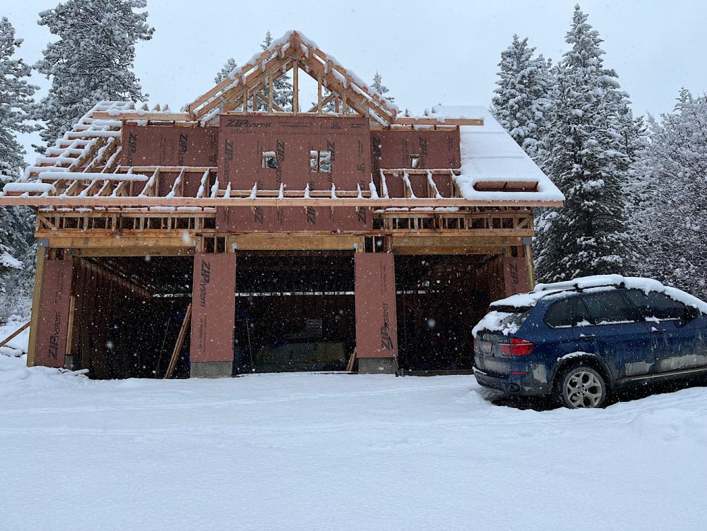
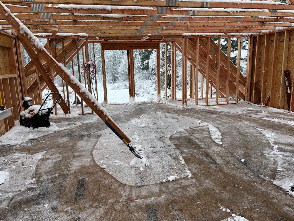
Posted by: mgarrison Jan 8 2024, 11:44 AM
Amazing looking garage build!
I'm hoping of some day building a barn/shop/garage/house. Taking note of some cool ideas!
Posted by: Dion Jan 8 2024, 11:53 AM
Phil, that garage will be perfect. You made great progress despite some setbacks with mother nature. Love the design. Keep going mate.
The 914 will be home soon.
Posted by: Superhawk996 Apr 13 2024, 10:40 AM
Yesterday was a milestone day, last bit of sheathing went on the roof. Due to ZIP system sheathing and flashing tape on seams it’s quasi dried in. Obviously not counting the wall sheathing that needs to get done. 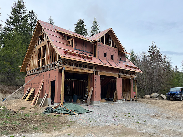
Winter weather really slowed progress due to rain, snow, sleet, frost that limited how many hours a day I could actually get up on the roof. But each progressive section that got sheathed meant less shoveling of snow off the floor and less water inside.
Thankfully spring is here and days are getting longer and it’s more enjoyable to be outside daily.
Need to get AZEK fascia boards up and the walls sheathed that protrude though the roof line then I can get a real roof installed. ZIP is rated for 180 days exposure so I’ve got plenty of time.
There are days that are overwhelming and progress is slow but considering that I’m building solo and that I didn’t start framing until mid June of ‘23, I don’t think I’m doing too bad.
Someday the 914 will be back on the to do list.
Posted by: 930cabman Apr 13 2024, 12:16 PM
Milestone days always are deserving of much praise.
Great progress through the winter months, keep working safe
Posted by: bkrantz Apr 13 2024, 09:25 PM
Looks great. Getting a building weather-tight (or almost) is a big achievement.
Powered by Invision Power Board (http://www.invisionboard.com)
© Invision Power Services (http://www.invisionpower.com)