Printable Version of Topic
Click here to view this topic in its original format
914World.com _ 914World Garage _ Wiring Diagram
Posted by: BPic Apr 21 2019, 01:34 PM
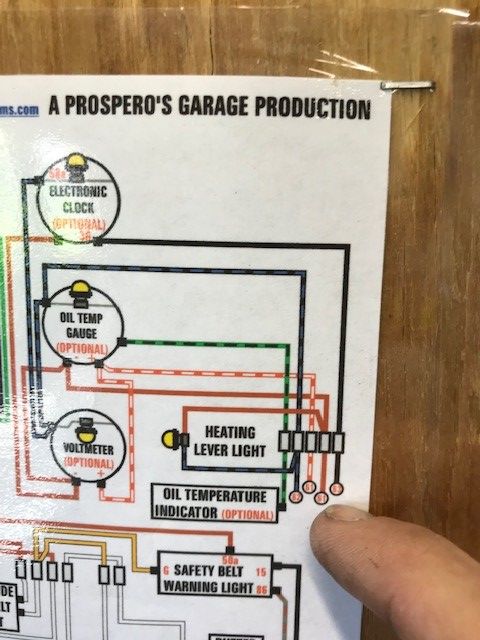
I have my harness out and I'm cleaning and replacing some wires. I'm also adding wires for AC and few other goodies. I want to have a center console with gauges and I'm stuck on this diagram. What do the numbers I'm pointing at reference? 
Posted by: Rand Apr 21 2019, 01:55 PM
Depends on the manual/chart, but I'd figure identifying circuits so you can pick them up on other parts of the charts. Only so much room on a page, gotta point to other sections where the circuits continue.
Posted by: GregAmy Apr 21 2019, 01:59 PM
Are there number markings at the bottom of the chart? I don't recognize that chart but factory electrical diagrams have that. If so, that number refers to the line number at the bottom where that circuit continues.
Posted by: BPic Apr 21 2019, 02:16 PM
Thats exactly what I thought. However there is no other 62 or 63 on the diagrams. Theres a 61 for the Stop Light Switch on the first page. I want to find which wires to tap into to add the gauges in a center console.
Posted by: jcd914 Apr 21 2019, 05:42 PM
They are continuation indicators, the circuit continues on the other diagram page.
I guess since there were only 2 pages to the diagram they figure just a matching number was enough for you to find the other part of the circuit.
The latter diagrams are what they call current flow diagrams and they have track numbers at the bottom of the page and those are what is used to reference the continuation of the circuit.
For your current case: 62 is above the light switch (28) and 63 is at the interior light (16).
Jim
Posted by: narino Apr 21 2019, 06:30 PM
Bpic - the numbers are wrong in that location. I had the same confusion when I received the diagram. When I get home I'll post my notes on what the correct numbers and labels should be.
*edit* Here are the errors I've caught so far on my diagram, which is for 72-73 years.
Page 1/2
Light Switch:
- Wire from pin 15 missing wire number 14 at end.
- Wire from pin 58a wrong wire number at end (51). Should be 62.
Page 2/2
Relay for Fresh Air:
- Wire to pin 86 should be RD/WH, also missing wire number 14 at end.
Heating Lever Light:
- Brown wire number wrong (61). Should be 64.
Hope that helps.
Posted by: GregAmy Apr 21 2019, 07:52 PM
Here's a link to the factory diagrams:
http://web.archive.org/web/20120325182607/https://www.pelicanparts.com/914/914_electrical_diagrams.htm
Posted by: tmc914 Apr 21 2019, 07:52 PM
Page 1/2
Light Switch:
- Wire from pin 15 missing wire number 14 at end.
- Wire from pin 58a wrong wire number at end (51). Should be 62.
Page 2/2
Relay for Fresh Air:
- Wire to pin 86 should be RD/WH, also missing wire number 14 at end.
Heating Lever Light:
- Brown wire number wrong (61). Should be 64.
Hope that helps.
Yes, this info helps a lot. Struggled with those errors early on but someone was able to help with a current diagram to bail me out. Hopefully others will see this in time so they don't struggle with errors on diagram.
Posted by: BPic Apr 22 2019, 04:26 AM

Bpic - the numbers are wrong in that location. I had the same confusion when I received the diagram. When I get home I'll post my notes on what the correct numbers and labels should be.
*edit* Here are the errors I've caught so far on my diagram, which is for 72-73 years.
Page 1/2
Light Switch:
- Wire from pin 15 missing wire number 14 at end.
- Wire from pin 58a wrong wire number at end (51). Should be 62.
Page 2/2
Relay for Fresh Air:
- Wire to pin 86 should be RD/WH, also missing wire number 14 at end.
Heating Lever Light:
- Brown wire number wrong (61). Should be 64.
Hope that helps.
Huh. Guess I didn’t even think that the diagram could be wrong. This is starting to make sense since all the items you pointed I had notes to double check because they just didn’t make sense.
Thank you.
Posted by: Tbrown4x4 Apr 22 2019, 04:42 AM
I also found some errors in the Prospero's diagram. I probably should let them know so they can be corrected.
Probably the same as narino found.
Powered by Invision Power Board (http://www.invisionboard.com)
© Invision Power Services (http://www.invisionpower.com)