Printable Version of Topic
Click here to view this topic in its original format
914World.com _ 914World Garage _ 2.7 CIS
Posted by: John Aug 13 2019, 09:09 AM
I tried searching, but didn't get much.
What is involved with fitting a 2.7 with CIS in a 914? I can figure out the plumbing and the electrical, but I believe that I had read long ago that it was a PITA to fit CIS without cutting anything or perhaps a mixture of different parts could be used or parts of the intake could be relocated in order to get it all to fit. I'd prefer to avoid cutting this 914 engine compartment since I'm trying to make this one appear mostly factory. Any advice or better yet pictures would be appreciated.
I'd rather not go with carbs, since I believe that I'd need to swap cams and pistons in order to do it right.
This one is only going to be a fun street car (I already have a dedicated track car)
(All my conversion experience has been with 3.2s, but I have this body, and I have this engine...)
Thanks in advance!
Posted by: GregAmy Aug 13 2019, 09:16 AM
Contact Chris Foley, Tangerine Racing. He was involved in this project, possibly as the installer? If not, he and Ed certainly worked on/maintained it.
https://bringatrailer.com/listing/1973-porsche-914-23/
I still kick myself daily for not buying that car. Really grinds my gears to have missed that one...
Posted by: Tdskip Aug 13 2019, 09:19 AM
Subscribing. I have been told it is possible, maybe with a Naro engine mount to help control the height of the engine?
Posted by: Porschef Aug 13 2019, 09:29 AM

I still kick myself daily for not buying that car. Really grinds my gears to have missed that one...
No doubt...

Posted by: mb911 Aug 13 2019, 10:14 AM
You actually rotate the cis 180 degrees and rebolt down.. It is pretty straight forward..
Let me know if I can help.. Also note the naro mount drops the height of the engine approximately 3/4" and will NOT allow for a stock scavange line..
Posted by: morgan_harwell Aug 13 2019, 10:22 AM
I did this in 1987 with a 2.4L CIS engine. I did not need to cut up the engine bay or rotate the injection system in any direction.
1. I moved the engine lid latch assembly from the Driver's side to the Passenger side of the engine bay to make room for the CIS (requires some spot welds and making a longer release cable). The engine lid is designed for the latch pin assembly to be mounted on Driver's or Passenger side, so I moved it to the Passenger side on my original lid(again a couple of spot welds involved). Many years later, when I ordered a GT Lid from PCA7GGR, I had Sergio perform the same modification to the GT Lid before he painted it.
2. I relocated a CIS item from the rear-top of the CIS assembly (I think an altitude compensation part, has 3 hoses attached to it) to below the CIS assembly. I attached it to the lower part of the #6 intake manifold.
3. I replaced the fuel fitting on the back of the CIS Fuel Distributor. The original fitting came straight out of the FD directly into the rear firewall, so I replaced it with a welded up 90 degree banjo fitting.
4. I used the Becker Engineering 6-conversion mount at the time (1987). I will be switching that out this year (2019) for the Naro Mount, so that I can install the MB911 Heat Exchangers I bought a couple of years ago.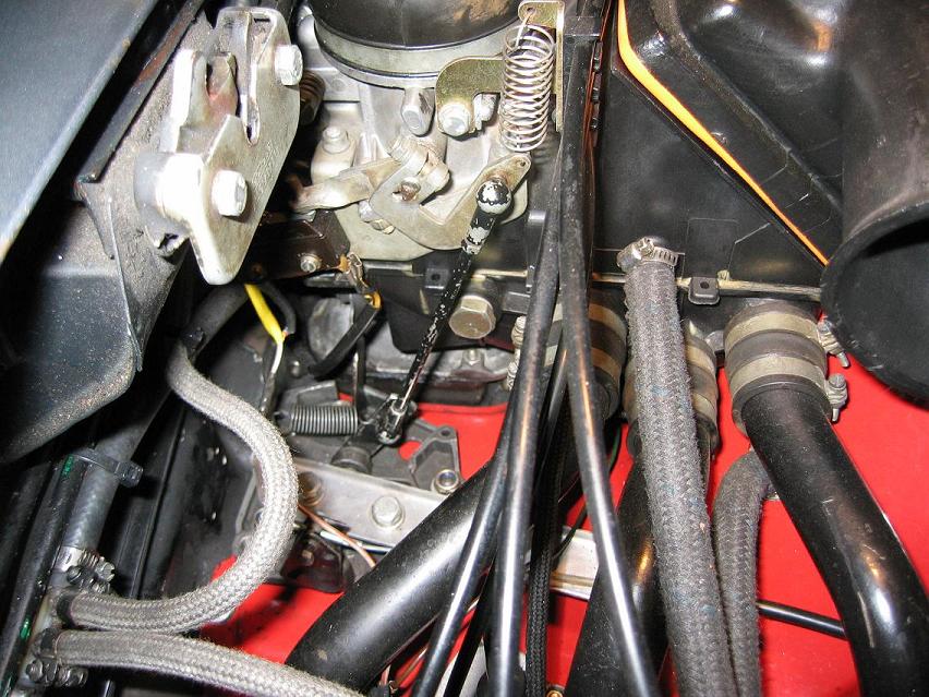
Posted by: John Aug 13 2019, 10:23 AM
Contact Chris Foley, Tangerine Racing. He was involved in this project, possibly as the installer? If not, he and Ed certainly worked on/maintained it.
https://bringatrailer.com/listing/1973-porsche-914-23/
I still kick myself daily for not buying that car. Really grinds my gears to have missed that one...
Whose car was that? It had one of my tri-gauges in it. Too bad there weren't too many pictures of the engine. That car is about what I'm considering building this one to look except with flares.
Posted by: John Aug 13 2019, 10:28 AM
You actually rotate the cis 180 degrees and rebolt down.. It is pretty straight forward..
Let me know if I can help.. Also note the naro mount drops the height of the engine approximately 3/4" and will NOT allow for a stock scavange line..
Do you know for a fact that it's possible to rotate the intake 180 degrees and have it fit or did you hear that second hand? I can try that on a stand and see if it all works before attempting to stuff it in the car.
I will probably make my own mount and sheet metal again. It worked well with the 3.2s I did.
P.S. I may want to talk to you about exhaust.
Posted by: Dr Evil Aug 13 2019, 11:01 AM
You actually rotate the cis 180 degrees and rebolt down.. It is pretty straight forward..
Let me know if I can help.. Also note the naro mount drops the height of the engine approximately 3/4" and will NOT allow for a stock scavange line..
Do you know for a fact that it's possible to rotate the intake 180 degrees and have it fit or did you hear that second hand? I can try that on a stand and see if it all works before attempting to stuff it in the car.
I will probably make my own mount and sheet metal again. It worked well with the 3.2s I did.
P.S. I may want to talk to you about exhaust.
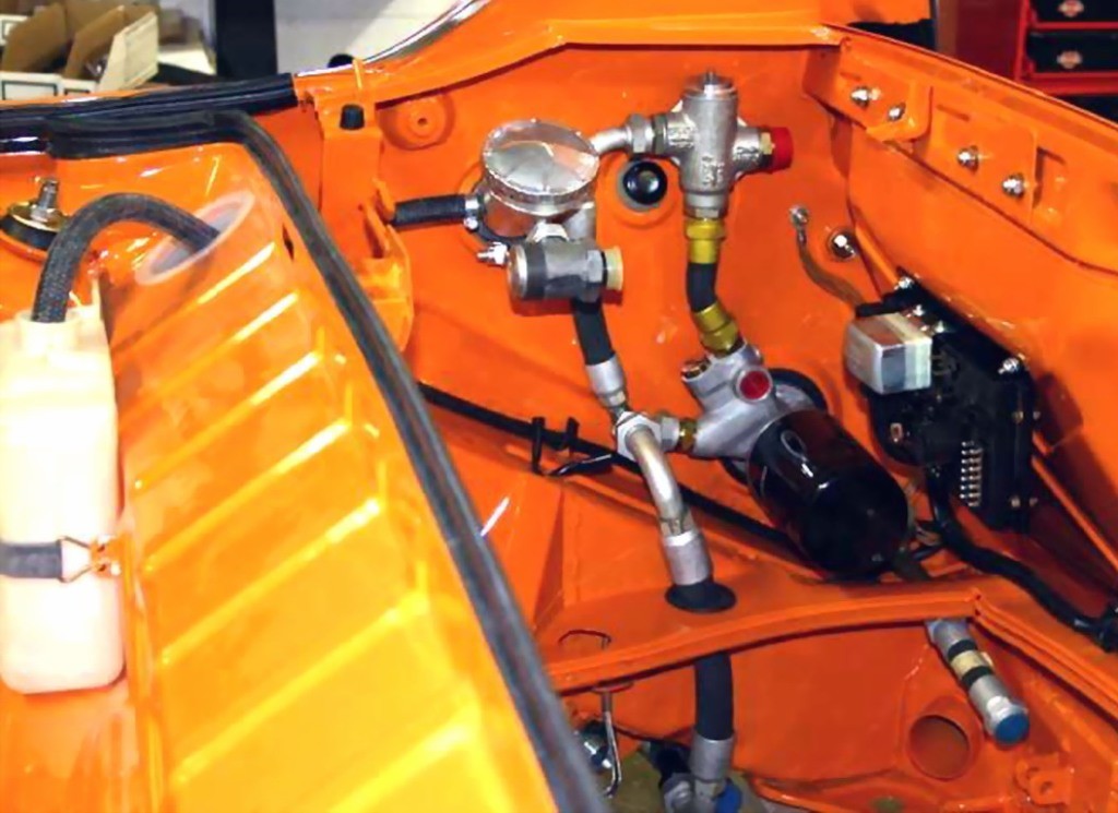
I have a conversion with a 2.7 running CIS. The you can rotate it no prob. Mine fit with minimal strife and modification. It is hours away from me at a body shop and the engine is out so cant take new pics, but if you search my conversion all the pics are there.
Posted by: John Aug 13 2019, 11:31 AM
I have a conversion with a 2.7 running CIS. The you can rotate it no prob. Mine fit with minimal strife and modification. It is hours away from me at a body shop and the engine is out so cant take new pics, but if you search my conversion all the pics are there.
Tried searching, but came up with nothing. You have given me hope that it will fit. I suppose I need to go for it and see what I need to change in order to get it to fit.
Posted by: Dr Evil Aug 13 2019, 11:41 AM
I have a conversion with a 2.7 running CIS. The you can rotate it no prob. Mine fit with minimal strife and modification. It is hours away from me at a body shop and the engine is out so cant take new pics, but if you search my conversion all the pics are there.
Tried searching, but came up with nothing. You have given me hope that it will fit. I suppose I need to go for it and see what I need to change in order to get it to fit.
Ya, I tried searching as well. Did the conversion in 2005. Had good pics and notes. Cant find it. Tried to use google as well...found lots of my transmission propaganda, but not my car. If you can find my threads from about 2004-2007 you will see good pics and info on what I did and fought with. I took out the rain tray and cut the engine bat release cable and tube out and make it pin down type. This gave me plenty of room. You unscrew the pressure manifold and simply rotate it and screw it back in. IIRC, 3 screws so can actually rotate less than 180, or more. I moved mine sideways, if I am not mistaken. Pics on home computer.
Fuel pump plumbing is different. Need the fuel pump, very high pressure. I replaced all my hoses with clear, new hoses for like $12 from NAPA. I did find the thread mentioning that. Boil water and push on to nipples, hard (man, that reads wrong).
Posted by: Jetsetsurfshop Aug 13 2019, 11:48 AM
You actually rotate the cis 180 degrees and rebolt down.. It is pretty straight forward..
Let me know if I can help.. Also note the naro mount drops the height of the engine approximately 3/4" and will NOT allow for a stock scavange line..
Dropping the engine height 3/4 doest sound like a bad thing to me. I'm I missing something here on that statement?
Posted by: mb911 Aug 13 2019, 11:49 AM
If you want to make your engine sheet metal let me know.. I have laser cuts I can sell them to you and you can form them for 150..
Posted by: mb911 Aug 13 2019, 11:51 AM
You actually rotate the cis 180 degrees and rebolt down.. It is pretty straight forward..
Let me know if I can help.. Also note the naro mount drops the height of the engine approximately 3/4" and will NOT allow for a stock scavange line..
Dropping the engine height 3/4 doest sound like a bad thing to me. I'm I missing something here on that statement?
No not bad but the rear engine to sheet metal seal no longer seals and the engine mount is in the way of the stock oil line.. I am going to now be supplying soft line scavange lines with heat exchangers as soon as I make them up and figure out pricing..
Posted by: Jetsetsurfshop Aug 13 2019, 12:10 PM
You actually rotate the cis 180 degrees and rebolt down.. It is pretty straight forward..
Let me know if I can help.. Also note the naro mount drops the height of the engine approximately 3/4" and will NOT allow for a stock scavange line..
Dropping the engine height 3/4 doest sound like a bad thing to me. I'm I missing something here on that statement?
No not bad but the rear engine to sheet metal seal no longer seals and the engine mount is in the way of the stock oil line.. I am going to now be supplying soft line scavange lines with heat exchangers as soon as I make them up and figure out pricing..
I just bought one of Naro's mount. I'm sure I can deal with the engine tin. Thanks for the info.
Posted by: sixnotfour Aug 13 2019, 01:00 PM
one way to do it...
http://www.914world.com/bbs2/index.php?act=ST&f=2&t=39740&hl=engine&st=20
Attached image(s)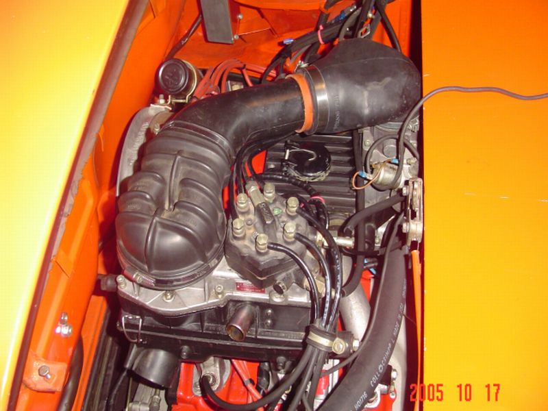
Posted by: 914_teener Aug 13 2019, 01:07 PM
Slits (RIP) had a 2.7 with CIS IIRC.
I don't think he posted much on it but I saw the car running several times. It fit neatly and I always thought that the system itself is ingenious.
IIRC the hardest thing was the fuel accumulator and the fuel pump since it runs at high pressure.
Posted by: sixnotfour Aug 13 2019, 01:22 PM
Jeff Tucker wrote;
Attached image(s)
Posted by: sixnotfour Aug 13 2019, 01:23 PM
last
Attached image(s)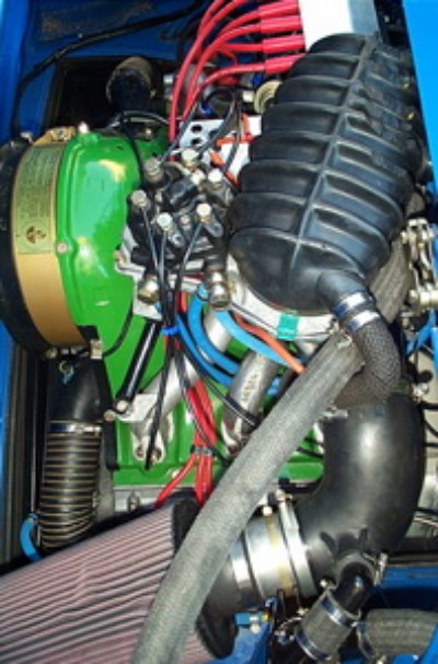
Posted by: sixnotfour Aug 13 2019, 01:52 PM
@Dr Evil
http://www.914world.com/bbs2/index.php?showtopic=32819&st=20
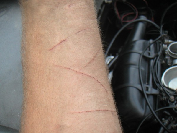
I lost a lot of blood yesterday with all of the metal cutting.
Attached image(s)
Posted by: mepstein Aug 13 2019, 02:39 PM
I have a conversion with a 2.7 running CIS. The you can rotate it no prob. Mine fit with minimal strife and modification. It is hours away from me at a body shop and the engine is out so cant take new pics, but if you search my conversion all the pics are there.
Tried searching, but came up with nothing. You have given me hope that it will fit. I suppose I need to go for it and see what I need to change in order to get it to fit.
Ya, I tried searching as well. Did the conversion in 2005. Had good pics and notes. Cant find it. Tried to use google as well...found lots of my transmission propaganda, but not my car. If you can find my threads from about 2004-2007 you will see good pics and info on what I did and fought with. I took out the rain tray and cut the engine bat release cable and tube out and make it pin down type. This gave me plenty of room. You unscrew the pressure manifold and simply rotate it and screw it back in. IIRC, 3 screws so can actually rotate less than 180, or more. I moved mine sideways, if I am not mistaken. Pics on home computer.
Fuel pump plumbing is different. Need the fuel pump, very high pressure. I replaced all my hoses with clear, new hoses for like $12 from NAPA. I did find the thread mentioning that. Boil water and push on to nipples, hard (man, that reads wrong).
Mike - is that engine in your green car?
Posted by: sixnotfour Aug 13 2019, 02:59 PM
I have a conversion with a 2.7 running CIS. The you can rotate it no prob. Mine fit with minimal strife and modification. It is hours away from me at a body shop and the engine is out so cant take new pics, but if you search my conversion all the pics are there.
Tried searching, but came up with nothing. You have given me hope that it will fit. I suppose I need to go for it and see what I need to change in order to get it to fit.
Ya, I tried searching as well. Did the conversion in 2005. Had good pics and notes. Cant find it. Tried to use google as well...found lots of my transmission propaganda, but not my car. If you can find my threads from about 2004-2007 you will see good pics and info on what I did and fought with. I took out the rain tray and cut the engine bat release cable and tube out and make it pin down type. This gave me plenty of room. You unscrew the pressure manifold and simply rotate it and screw it back in. IIRC, 3 screws so can actually rotate less than 180, or more. I moved mine sideways, if I am not mistaken. Pics on home computer.
Fuel pump plumbing is different. Need the fuel pump, very high pressure. I replaced all my hoses with clear, new hoses for like $12 from NAPA. I did find the thread mentioning that. Boil water and push on to nipples, hard (man, that reads wrong).
Mike - is that engine in your green car?
his grey 914 at scotty's.....????
Posted by: Dr Evil Aug 14 2019, 06:13 AM
I have a conversion with a 2.7 running CIS. The you can rotate it no prob. Mine fit with minimal strife and modification. It is hours away from me at a body shop and the engine is out so cant take new pics, but if you search my conversion all the pics are there.
Tried searching, but came up with nothing. You have given me hope that it will fit. I suppose I need to go for it and see what I need to change in order to get it to fit.
Ya, I tried searching as well. Did the conversion in 2005. Had good pics and notes. Cant find it. Tried to use google as well...found lots of my transmission propaganda, but not my car. If you can find my threads from about 2004-2007 you will see good pics and info on what I did and fought with. I took out the rain tray and cut the engine bat release cable and tube out and make it pin down type. This gave me plenty of room. You unscrew the pressure manifold and simply rotate it and screw it back in. IIRC, 3 screws so can actually rotate less than 180, or more. I moved mine sideways, if I am not mistaken. Pics on home computer.
Fuel pump plumbing is different. Need the fuel pump, very high pressure. I replaced all my hoses with clear, new hoses for like $12 from NAPA. I did find the thread mentioning that. Boil water and push on to nipples, hard (man, that reads wrong).
Mike - is that engine in your green car?
his grey 914 at scotty's.....????
Your search prowess is rock solid!
The green engine is not mine. The primer car is at Scotty’s. I have no parking for it.
Posted by: billh1963 Aug 14 2019, 01:13 PM
Send member adidas a PM. He is working on my ‘72 914 with CIS 2.7 right now. He can probably take pictures for you.
Posted by: John Aug 28 2019, 11:48 AM
I did this in 1987 with a 2.4L CIS engine. I did not need to cut up the engine bay or rotate the injection system in any direction.
1. I moved the engine lid latch assembly from the Driver's side to the Passenger side of the engine bay to make room for the CIS (requires some spot welds and making a longer release cable). The engine lid is designed for the latch pin assembly to be mounted on Driver's or Passenger side, so I moved it to the Passenger side on my original lid(again a couple of spot welds involved). Many years later, when I ordered a GT Lid from PCA7GGR, I had Sergio perform the same modification to the GT Lid before he painted it.
2. I relocated a CIS item from the rear-top of the CIS assembly (I think an altitude compensation part, has 3 hoses attached to it) to below the CIS assembly. I attached it to the lower part of the #6 intake manifold.
3. I replaced the fuel fitting on the back of the CIS Fuel Distributor. The original fitting came straight out of the FD directly into the rear firewall, so I replaced it with a welded up 90 degree banjo fitting.
4. I used the Becker Engineering 6-conversion mount at the time (1987). I will be switching that out this year (2019) for the Naro Mount, so that I can install the MB911 Heat Exchangers I bought a couple of years ago.
I like the thought of leaving most of the CIS as is. Does that car still use a stock air filter? (I know it is a 2.4 and mine is a 2.7, but they should be similar) I'm going to have to get off my butt and pull the big dent and get this project moving forward. I suppose I will bolt a trans onto the engine and see what it looks like jacked up into position. I could easily move the engine lid latch and release mech to the passenger side. The franken-tub is cleaner than I remembered. The guy in Mason City did claim it was a CA car, but it has (2) two 76/76 front fenders and front panel on it.
Posted by: morgan_harwell Aug 28 2019, 02:59 PM
I did this in 1987 with a 2.4L CIS engine. I did not need to cut up the engine bay or rotate the injection system in any direction.
1. I moved the engine lid latch assembly from the Driver's side to the Passenger side of the engine bay to make room for the CIS (requires some spot welds and making a longer release cable). The engine lid is designed for the latch pin assembly to be mounted on Driver's or Passenger side, so I moved it to the Passenger side on my original lid(again a couple of spot welds involved). Many years later, when I ordered a GT Lid from PCA7GGR, I had Sergio perform the same modification to the GT Lid before he painted it.
I like the thought of leaving most of the CIS as is. Does that car still use a stock air filter? (I know it is a 2.4 and mine is a 2.7, but they should be similar)
Yes, my 914 with 2.4L uses a stock CIS air filter, which is the same part number as 2.7L or 3.0L (1973-1983). Though I did not need to, I replaced the air-filter cover with one off a 911SC (shorter snorkel).
Posted by: johnlush Aug 28 2019, 05:53 PM
The car referenced in posts 2 and 7 is mine. I started the conversion in the late 90's and never got it finished before trading it to my bro-in-law for his wrecked '71 /6. He had the conversion finished in CA. There was some less than craftsman type work done during that time even though it was done at a well respected shop. My bro-in-law drove it for several years before selling it on BaT to a guy in NY. He had Chris do some work on it during his ownership but only drove it about 70 miles the whole time before listing it back on BaT. I'm so happy to have it back and continue to refine it. The 2.4 CIS engine is just perfect. Starts and runs great and just a really nice balance for a narrow-body car. I'm happy to take pics or whatever on how the CIS pluming/wiring all fits in to the engine compartment if that would be of help.
Posted by: live free & drive Aug 31 2019, 10:34 AM
" Also note the naro mount drops the height of the engine approximately 3/4" and will NOT allow for a stock scavange line.."
Does anyone think this requires the dropping of the transaxle mounts also - to keep the shift console aligned?
Posted by: mb911 Aug 31 2019, 10:49 AM
" Also note the naro mount drops the height of the engine approximately 3/4" and will NOT allow for a stock scavange line.."
Does anyone think this requires the dropping of the transaxle mounts also - to keep the shift console aligned?
In theory probably. I will let you know as I finish my clients conversion up..
Posted by: John Sep 2 2019, 08:33 PM
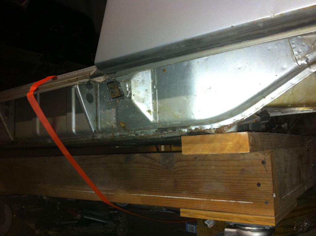
Well, I repaired the passenger side outer longitudinal with a replacement part from RD and all went fine so I'll continue on with this car. I was surprised with the absence of rust inside the the box section that I replaced. I still need to grind down my plug welds. In general, this car is mostly rust free, but it had been in at least a few crashes.
It does measure out, according to the workshop manuals.
Now I get to proceed on to re-fitting the 75 front fenders and back dating them as well as modifying the miscellaneous reinforcements for the front trunk (the front panel is obviously different from the earlier cars that I have).
Does a stock 2.7 need a front cooler? I'm not sure, but if it needs one, I may want to mount the lines like a GT on the drivers side under the rocker panel. My last conversion, I went through the heater tubes as it has headers and no heat anyway, but now some folks seem to offer heat exchangers for conversion cars...
Posted by: mepstein Sep 2 2019, 08:51 PM
Ben/914-6Werkshop.com has the GT hard lines and stainless steel heat exchangers. You could run the car as-is and then decide if you need a front cooler. It depends on the climate, the engine, driving style, ect. Some engines run hotter than others no matter what.
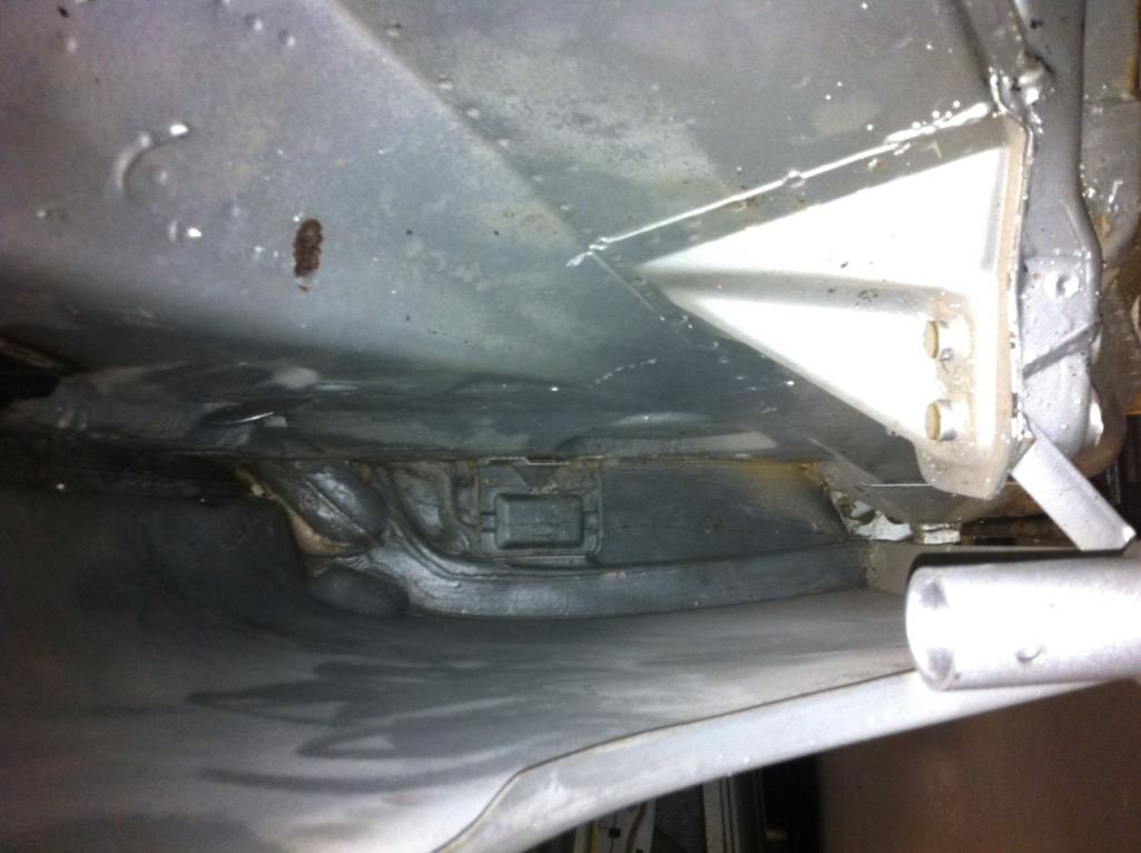
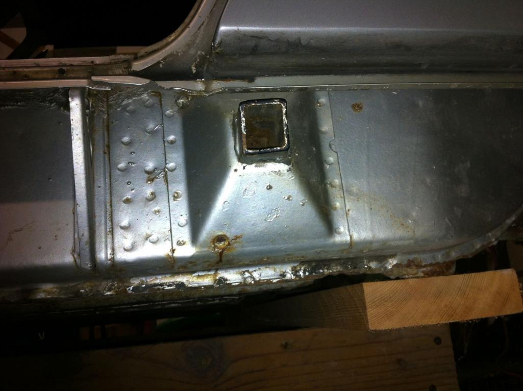
Posted by: John Sep 10 2019, 02:50 PM
A couple of pictures of what I'm dealing with...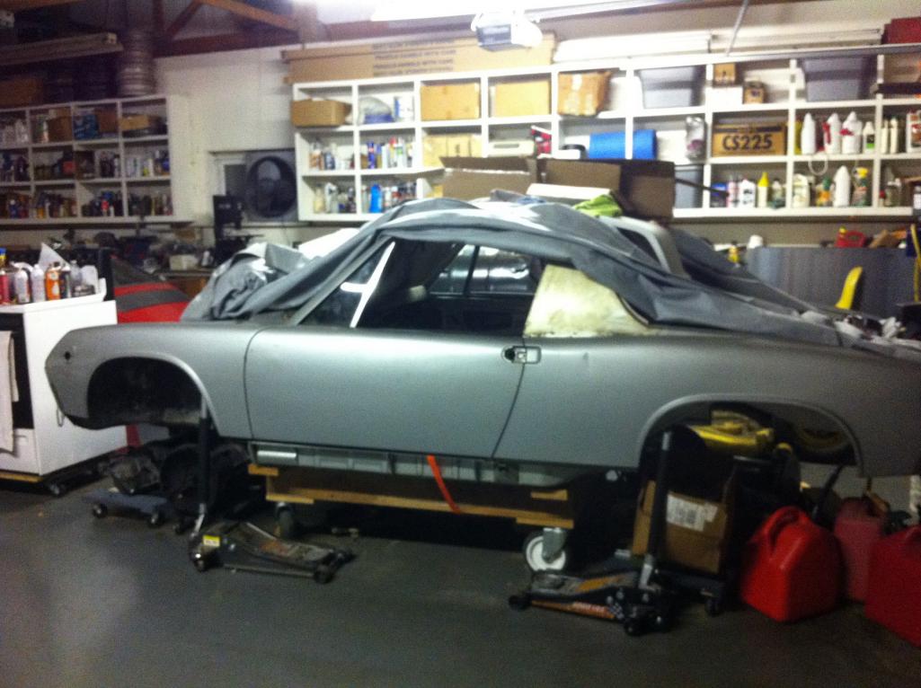
Posted by: John Sep 23 2019, 08:35 AM
Were all 914 Bodies painted white before color was applied?
I had heard this rumor a long time ago and believed it to some extent, but now with this current car, I believe it even more.
I was cleaning the glue off of the sail panels with glue remover and the 45 year old glue is coming off after some effort. Under the glue is glossy original paint down low on the sail panel, but the higher up I get, the silver fades away and I'm left with gloss white up at the top of the roll bar. I'm fairly certain that the white is factory applied paint, but was the whole car painted white first or just the upper portion of the roll bar? Why would they have done this, just to keep them from rusting prior to actual color application? This 914 shell has the most in-tact original paint that I have started a project with. I'm so glad that this one really has nearly zero rust to deal with.
I'm guessing this topic is already covered somewhere, but I can't seem to click on the search function today.
Posted by: mepstein Sep 23 2019, 08:46 AM
No
Posted by: mb911 Sep 23 2019, 09:22 AM
Maybe just white primer?
Posted by: John Sep 24 2019, 08:43 AM
I don't believe it to be primer as it seems too glossy and also, the primer under the tar on the floors is indeed gray. I only removed tar in a spot where it crumbled, but primered sheet metal was underneath.
Posted by: mepstein Sep 24 2019, 09:34 AM
So many things done to these cars over 50 years.
Posted by: John Sep 27 2019, 11:34 AM
So many things done to these cars over 50 years.
That's my point. This car hasn't had much done to it. Probably in storage more than it was driven. Too bad they stripped all the stuff off and sold it piece by piece. I should have started on this 12 years ago, but life gets in the way sometimes.
Posted by: stevesc_us Sep 28 2019, 08:21 AM
Forget all that CIS crap and make it look old school by converting to an EFI/ITB set up like I did on one of my early 911’s. The PMO ITB’s look just like carbs which is why I went that route. 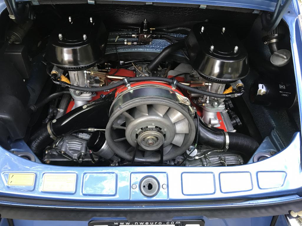
Posted by: JmuRiz Oct 1 2019, 12:56 PM
Forget all that CIS crap and make it look old school by converting to an EFI/ITB set up like I did on one of my early 911’s. The PMO ITB’s look just like carbs which is why I went that route.
I think we'd all like a setup like that, but $9k for everything is a tough pill to swallow (ITBs, AEM setup and all the fixin's)!!!
If it were in the 2-3k range I think we'd all be running that on our /6 conversions.
Posted by: John Oct 1 2019, 03:05 PM
That is certainly one way to go.
I already have what I have and will use the CIS. in my 74 914 body.
Posted by: Justinp71 Oct 1 2019, 05:48 PM
My uncle and I did a 2.7 install 15 years ago. We had an earlier CIS that had less components (not sure when they added more components, but I know the 3.0 version has more for sure). We just removed the engine lid latch afaik and secured it with hood pins. You can also rotate it 180 degrees as from what others have said. If you have a later model CIS there is a valve on the back side that interferes with the trunk and I believe you need to rotate the CIS or make other modifications.
Posted by: Dr Evil Oct 2 2019, 10:07 AM
My uncle and I did a 2.7 install 15 years ago. We had an earlier CIS that had less components (not sure when they added more components, but I know the 3.0 version has more for sure). We just removed the engine lid latch afaik and secured it with hood pins. You can also rotate it 180 degrees as from what others have said. If you have a later model CIS there is a valve on the back side that interferes with the trunk and I believe you need to rotate the CIS or make other modifications.
I cut out the guide tube for the lid release cable...didnt have to, followed bad advice. See how it fits with your mount, and rotated fuel distributor and any slight mods will be simple. CIS is great once it id dialed in. I wanted to use what I had, and make a nice street car, not a super car, but a fun, well mannered, all around sports car and the CIS will do that.
I did not run a cooler on my 2.7 CIS and lived in PA and drove around the East coast states (briefly, until I wrecked in....
 ). I do plan on putting a cooler in the current one when its done for the sake of safety for the engine and potential hilly hot runs which I have not tried yet.
Posted by: 914Toy Oct 2 2019, 12:43 PM
Forget all that CIS crap and make it look old school by converting to an EFI/ITB set up like I did on one of my early 911’s. The PMO ITB’s look just like carbs which is why I went that route.
SteveSC_US, Sent you a PM.
Posted by: John Sep 25 2020, 06:57 AM
Started doing the flares thing on this car.
Before: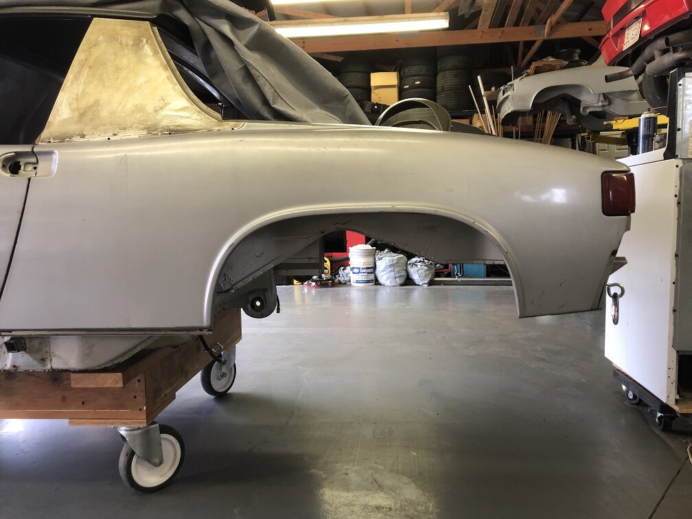
After: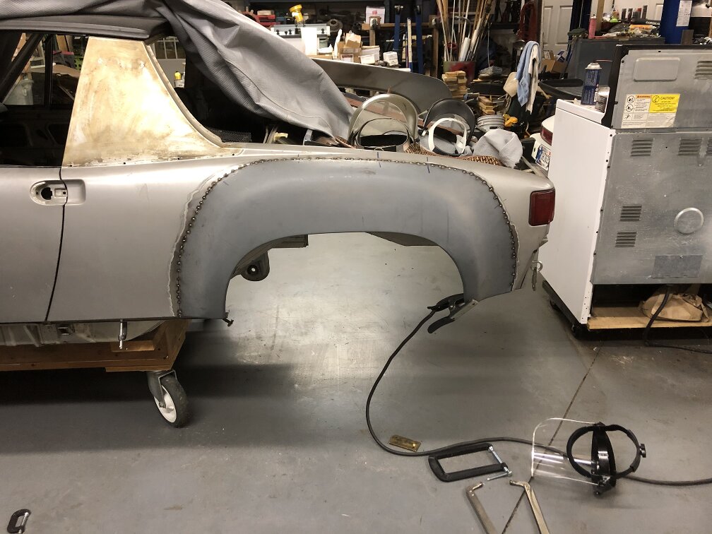
Posted by: Tdskip Sep 25 2020, 07:20 AM
Thanks for the update.
Where did you source the flares? Happy with the fit?
Posted by: John Sep 25 2020, 08:52 AM
Thanks for the update.
Where did you source the flares? Happy with the fit?
It's been so long ago, that I forget who I bought them from (it was an individual). I've had these for around 15 years. They were pressed out on the dies that AA and RD made around the time I bought these.
They fit well.
Posted by: Tdskip Sep 25 2020, 08:57 AM
Thanks for the update.
Where did you source the flares? Happy with the fit?
It's been so long ago, that I forget who I bought them from (it was an individual). I've had these for around 15 years. They were pressed out on the dies that AA and RD made around the time I bought these.
They fit well.
Good morning and thank you for the update.
Are you happy with the Naro engine mount? I am about to weld mine into the/6 project, seems like a good time to ask before I fire up the MIG.
Thanks!
Posted by: Root_Werks Sep 25 2020, 09:07 AM
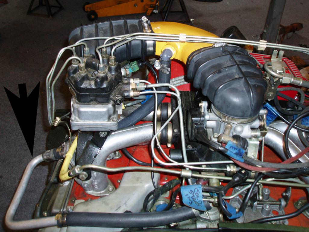
CIS is a better choice than most give it credit. It's very simple mechanical fuel injection only needing one electric pump. The 914-6 I bought was converted using a 2.7 with CIS. The PO turned the airbox 90 degrees instead of leaving alone. It's....interesting and gets in the way of the spark plugs. When I go to paint the 914, I'll pull the engine/trans and put things to a more stock or traditional position.
Posted by: John Sep 25 2020, 09:07 AM
Are you happy with the Naro engine mount? I am about to weld mine into the/6 project, seems like a good time to ask before I fire up the MIG.
Thanks!
I make my own engine mounts.
Before you weld it in, make sure the finished height of the engine is high enough to clear the shift rod. I've read here lately, that some folks have been having issues with that. Good luck on your project. As far as mine go, I have full size 3D models to compare with (aka complete cars).
Posted by: Root_Werks Sep 25 2020, 09:11 AM
Here's a shot of the engine:
Attached image(s)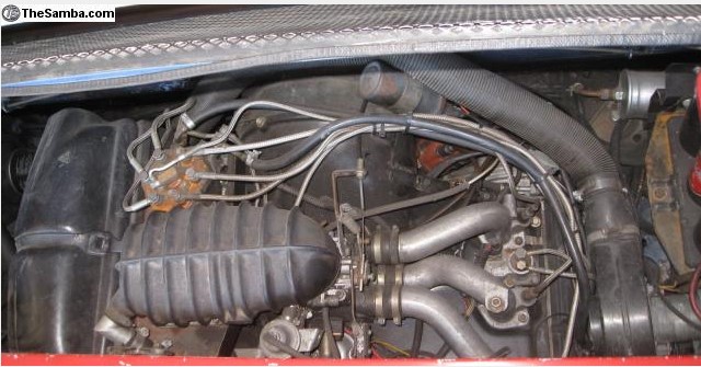
Posted by: Tdskip Sep 25 2020, 09:14 AM
Thank you @http://www.914world.com/bbs2/index.php?showuser=1615
Enjoy your updates, thanks for the posts.
Posted by: naro914 Sep 28 2020, 01:38 PM
Hey guys - someone pointed me to this thread as there seems to be a few questions about our 914/6 conversion mount.
I've never heard anyone say there was oil line or shift rod clearance issues.. we've sold over 3 dozen of these and use this mount in both of our own cars - Huey has a 3.2 stock engine with stock shift rod and stock oil tank location, and Papa Smurf has (had) a high compression engine based on a 930 case with the Tangerine Racing shift rod assembly and oil lines seemingly running everywhere throughout the car (oil tank up front). Both work fine. No need to space the trans mounts.
yes, it will sit your engine down a slight bit lower than stock, but that's because the mount needs to clear the brake bias assembly. All the aftermarket mounts have this issue.
FYI, we modeled this after the Patrick Motorsports mount - which I broke twice. My fabrication guy took one of the broken mounts and redesigned it for extra strength and support. Haven't broken it since, and we push over 360 hp through these mounts.
If anyone HAS run into an issue, please call or email me directly, I'd be interested in knowing what the issue is and if it's something we can rectify. But to date, the only one that we ever had a problem with turns out was installed upside down...oops...
Posted by: Maltese Falcon Sep 28 2020, 05:19 PM
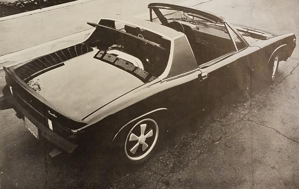
Enough real estate under that lid to stuff a 2.7L turbo sytem in there as well 
Posted by: Steve Sep 28 2020, 09:51 PM
Hey guys - someone pointed me to this thread as there seems to be a few questions about our 914/6 conversion mount.
I've never heard anyone say there was oil line or shift rod clearance issues.. we've sold over 3 dozen of these and use this mount in both of our own cars - Huey has a 3.2 stock engine with stock shift rod and stock oil tank location, and Papa Smurf has (had) a high compression engine based on a 930 case with the Tangerine Racing shift rod assembly and oil lines seemingly running everywhere throughout the car (oil tank up front). Both work fine. No need to space the trans mounts.
yes, it will sit your engine down a slight bit lower than stock, but that's because the mount needs to clear the brake bias assembly. All the aftermarket mounts have this issue.
FYI, we modeled this after the Patrick Motorsports mount - which I broke twice. My fabrication guy took one of the broken mounts and redesigned it for extra strength and support. Haven't broken it since, and we push over 360 hp through these mounts.
If anyone HAS run into an issue, please call or email me directly, I'd be interested in knowing what the issue is and if it's something we can rectify. But to date, the only one that we ever had a problem with turns out was installed upside down...oops...
Wrong thread... @http://www.914world.com/bbs2/index.php?showuser=6073
http://www.914world.com/bbs2/index.php?showtopic=345537
Posted by: John Nov 5 2020, 10:34 PM
Anyone know or remember a member here REZRON? This tub was bought from him way back in 2005 and sat for many years (in my Dad's garage until 2016). It was supposed to be a tub from CA and had some damage to the passenger side long, and I knew both front fenders had been replaced and the passenger side wasn't attached. The hell hole is solid, and most of the rear end is rust free and original paint underneath.
The doors fit well enough (better than most I've seen). I replaced portions of the passenger side long after pulling the pinch seam back straight.
I started on the rear flares and all went well, so I moved to the front. Ran into issues in the front that I wasn't aware of. I knew the passenger side fender was not attached which I didn't mind, and I knew the drivers side had been replaced. What I had failed to notice was that the underside of the bottom of the front trunk was badly beaten up. The inside of the front trunk appeared straight.
Someone had used filler to flatten out the inside of the front trunk and failed to straighten out the sheet metal or even paint it during some repair at some point. I found this when beating out a dent inside the passenger side front inner fender and the bondo popped. Bad on me for not checking until now. I recall that REZRON was supposed to have been a a body shop person. Looking back, I should have known, but still makes me mad as there wasn't disclosure about the floor of the front trunk, the bulkhead in front of the gas tank and the area between the bulkhead and the firewall in front of the passenger compartment. After searching the threads and reading some of his threads from 15+ years ago, there were indications that someone in the past had performed some poor repairs in the front, but wasn't made clear at the time of sale. Luckily, this thing was cheap and it isn't rusty.
Many hours later (and much frustration), I have removed all the plastic filler in the front trunk, used a hammer and dolly (and other straightening devices for many hours and days) to straighten the floor, bulkhead, inner fenders, and area between the bulkhead and the firewall. Pretty sure I invented a few new phrases for DAPO's.
I have checked and verified the suspension pick-up points to be accurate and I can now proceed to re-attaching the passenger side front fender, and completing the flare installation. Restoration Design has some new pieces that I plan to purchase including a new gravel pan (bottom cover plate for steering rack). I hope to post some pictures of progress soon.
Posted by: John Dec 5 2020, 09:30 PM
So, nobody knows Rezron. Hmm. Anyway back to the project....
I have attached the passenger side fender and resumed tack welding the flares onto the front end. I have a few more sheet metal warps to work out, as well as a few more areas to give my attention, but I think this tub will be fine after the TLC that I am applying. I will eventually need some aluminum trim (roll bar and windshield frame) and possibly some early chrome bumpers to finish this thing (hint, hint... wink, wink, nudge, nudge, say no more).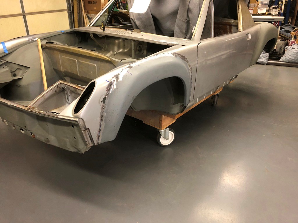
Posted by: Tdskip Dec 6 2020, 09:44 AM
Press on, it’s going to be great.
Posted by: watsonrx13 Dec 8 2020, 07:50 AM
Well done John. Do you have any in progress photos of a fender installation? Or can you write up the steps you used? Specifically I'm interested in how you mounted the fender to the car and how you cut the old fender, keeping the new fender in position.
Posted by: Root_Werks Dec 8 2020, 10:05 AM
Well done John. Do you have any in progress photos of a fender installation? Or can you write up the steps you used? Specifically I'm interested in how you mounted the fender to the car and how you cut the old fender, keeping the new fender in position.
I've installed 3 of the AA sets, pretty straight forward. I did one thread on it:
http://www.914world.com/bbs2/index.php?showtopic=89850&st=0
Looks like John is installing sort of similar. Looks great!
Posted by: John Dec 8 2020, 10:14 PM
Well done John. Do you have any in progress photos of a fender installation? Or can you write up the steps you used? Specifically I'm interested in how you mounted the fender to the car and how you cut the old fender, keeping the new fender in position.
I've installed 3 of the AA sets, pretty straight forward. I did one thread on it:
http://www.914world.com/bbs2/index.php?showtopic=89850&st=0
Looks like John is installing sort of similar. Looks great!
Watsonrx13,
Dan is mostly right. On this set of flares, I started the first one by carefully marking and cutting the fender then fitting the flare to the cut fender. The last three flares on this project were done how Dan showed in the thread he referenced. His thread is from a while ago, but it turned out far easier than cutting the whole fender at once.
The basic method used was to carefully measure and mark the bottoms of the flares to the existing fenders and starting tack welding and cutting about 7-8" at a time then tack welding. I moved from front to back and worked my way up to the tops of the flare as I went. They really do fit nicely. Take your time and put as little heat into the sheet metal as possible. I'm far better at MIG than TIG, so these are MIG welded one spot at a time.
I used measurements that seemed to match found on this site as well as on a Patrick Motorsports page to get the openings positioned fore-aft. I also used my existing full scale 3D model as a reference for dimensions.
Posted by: watsonrx13 Dec 9 2020, 06:57 AM
Thanks everyone.
Posted by: mb911 Dec 9 2020, 07:38 AM
Well done John. Do you have any in progress photos of a fender installation? Or can you write up the steps you used? Specifically I'm interested in how you mounted the fender to the car and how you cut the old fender, keeping the new fender in position.
I've installed 3 of the AA sets, pretty straight forward. I did one thread on it:
http://www.914world.com/bbs2/index.php?showtopic=89850&st=0
Looks like John is installing sort of similar. Looks great!
Watsonrx13,
Dan is mostly right. On this set of flares, I started the first one by carefully marking and cutting the fender then fitting the flare to the cut fender. The last three flares on this project were done how Dan showed in the thread he referenced. His thread is from a while ago, but it turned out far easier than cutting the whole fender at once.
The basic method used was to carefully measure and mark the bottoms of the flares to the existing fenders and starting tack welding and cutting about 7-8" at a time then tack welding. I moved from front to back and worked my way up to the tops of the flare as I went. They really do fit nicely. Take your time and put as little heat into the sheet metal as possible. I'm far better at MIG than TIG, so these are MIG welded one spot at a time.
I used measurements that seemed to match found on this site as well as on a Patrick Motorsports page to get the openings positioned fore-aft. I also used my existing full scale 3D model as a reference for dimensions.
On more tip would be to clamp a piece of wood at the bottom of the stock wheel arch then have it extend outward and sit the flare on it.. This will give the proper height.
Posted by: ClayPerrine Dec 9 2020, 04:01 PM
I did this in 1987 with a 2.4L CIS engine. I did not need to cut up the engine bay or rotate the injection system in any direction.
1. I moved the engine lid latch assembly from the Driver's side to the Passenger side of the engine bay to make room for the CIS (requires some spot welds and making a longer release cable). The engine lid is designed for the latch pin assembly to be mounted on Driver's or Passenger side, so I moved it to the Passenger side on my original lid(again a couple of spot welds involved). Many years later, when I ordered a GT Lid from PCA7GGR, I had Sergio perform the same modification to the GT Lid before he painted it.
2. I relocated a CIS item from the rear-top of the CIS assembly (I think an altitude compensation part, has 3 hoses attached to it) to below the CIS assembly. I attached it to the lower part of the #6 intake manifold.
3. I replaced the fuel fitting on the back of the CIS Fuel Distributor. The original fitting came straight out of the FD directly into the rear firewall, so I replaced it with a welded up 90 degree banjo fitting.
4. I used the Becker Engineering 6-conversion mount at the time (1987). I will be switching that out this year (2019) for the Naro Mount, so that I can install the MB911 Heat Exchangers I bought a couple of years ago.
I like the thought of leaving most of the CIS as is. Does that car still use a stock air filter? (I know it is a 2.4 and mine is a 2.7, but they should be similar) I'm going to have to get off my butt and pull the big dent and get this project moving forward. I suppose I will bolt a trans onto the engine and see what it looks like jacked up into position. I could easily move the engine lid latch and release mech to the passenger side. The franken-tub is cleaner than I remembered. The guy in Mason City did claim it was a CA car, but it has (2) two 76/76 front fenders and front panel on it.
I would suggest you look at this thread: http://www.914world.com/bbs2/index.php?showtopic=39740&hl=engine&st=0
Pictures of the setup are on page 2.
This is a CIS install, using an VW GTI airbox and some fittings. It doesn't require you to remove the engine lid latch or modify the engine compartment.
Clay
Posted by: John Dec 12 2020, 12:05 AM
I would suggest you look at this thread: http://www.914world.com/bbs2/index.php?showtopic=39740&hl=engine&st=0
Pictures of the setup are on page 2.
This is a CIS install, using an VW GTI airbox and some fittings. It doesn't require you to remove the engine lid latch or modify the engine compartment.
Clay
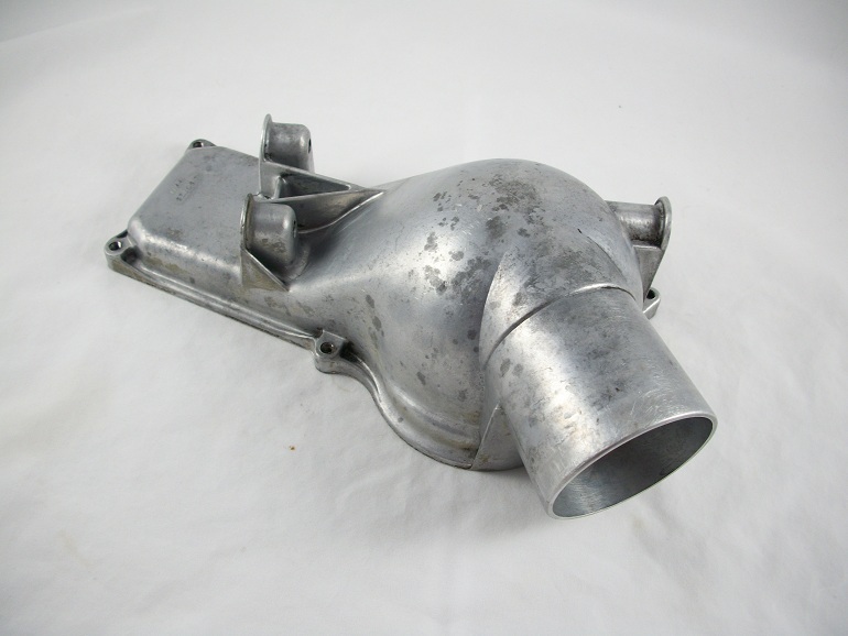
I looked at the thread and it is interesting. I can't find what airbox was used in that example, nor could I find the elbow that attaches to the throttle valve. In a similar thread, I read that DrEvil simply rotated the fuel distributor 60 degrees and things cleared, but I couldn't find a picture of that. The other problem I see with an airbox like in the thread that you referred to, is that it appears access to the air filter would be less than ideal. Do you know who pieced that system together?
Posted by: ClayPerrine Dec 12 2020, 06:57 AM
I would suggest you look at this thread: http://www.914world.com/bbs2/index.php?showtopic=39740&hl=engine&st=0
Pictures of the setup are on page 2.
This is a CIS install, using an VW GTI airbox and some fittings. It doesn't require you to remove the engine lid latch or modify the engine compartment.
Clay
I looked at the thread and it is interesting. I can't find what airbox was used in that example, nor could I find the elbow that attaches to the throttle valve. In a similar thread, I read that DrEvil simply rotated the fuel distributor 60 degrees and things cleared, but I couldn't find a picture of that. The other problem I see with an airbox like in the thread that you referred to, is that it appears access to the air filter would be less than ideal. Do you know who pieced that system together?
When I helped him out, the car was already like that. I do know the airbox was off a VW GTI, and I think the hose was too. The fuel distributor was from the 911, but it bolts to the airbox with no issues.
Changing the air filter is easy, just raise up the fuel distributor assembly. There is enough length in the hoses to allow it.
Clay
Posted by: John Dec 18 2020, 01:38 PM
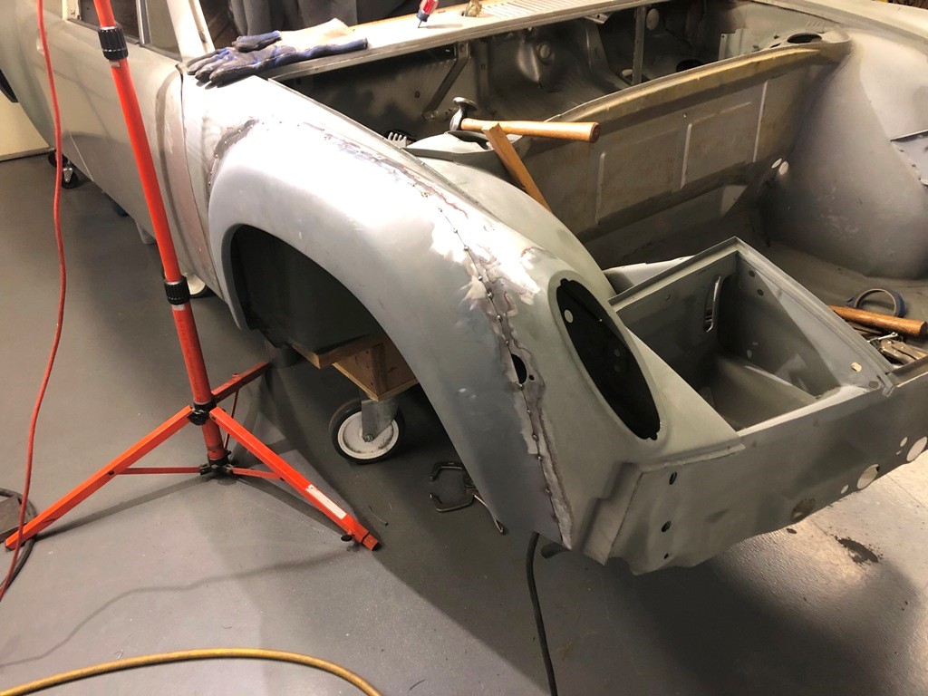
More progress being made and I have moved along to the engine compartment. I'm using an aftermarket oil tank (I believe it came from Patrick Motorsports maybe 10 years ago). Here is my current questions:
Are the holes into the inner fender simply centered on the embossed areas?
I've seen some hole sizes posted in other threads, would one or more of these holes be better if it were larger/smaller?
What is the best way to mark and cut the holes? I'm thinking of carefully marking and then using a plasma or a nibbler or a saw to open the holes larger and finishing off with a die grinder with a carbide burr or using sanding drums. I would think hole saws would be dangerous, but might make better round holes.
Do most folks remove the 4-cyl engine mounts or leave them? My last one, I cut them out and while it looks nice, I recall that it was a lot of effort.
Last one for now. What is the best way to reinforce the engine lid hinge mounts? I've never had one crack or fail, but both of them on this car have been welded or replaced. I typically have my hand on the engine lid when I pull the release cable to prevent the engine lid from springing open and hitting the back edge of the roll bar. I guess my dad must have taught me that.
Thanks again for your input.
Posted by: John Dec 18 2020, 07:12 PM
From various threads, I see a range of sizes for holes, some metric and some Imperial. Some larger and some smaller. Here is what I found and from measuring my tank, I made the attached full size 11x17 templates. I figure if I start with smaller holes, I can always make them larger, but it's tougher to go the other way.
One more question:
Does the fitting for the return line in the lower right corner also help support the tank or is the tank only held by the two 8mm studs (bolts in the case of my tank)?
These PDF's should be printed on 11x17 and no scaling. The centers match up with my tank (fabricated aluminum tank from Patrick Motorsports, but I think a member here actually made it) 914_6_Oil_Tank_Holes_11_17_1.pdf ( 7.19k )
Number of downloads: 98
914_6_Oil_Tank_Holes_11_17_2.pdf ( 5.89k )
Number of downloads: 91
914_6_Oil_Tank_Holes_11_17_1.pdf ( 7.19k )
Number of downloads: 98
914_6_Oil_Tank_Holes_11_17_2.pdf ( 5.89k )
Number of downloads: 91
Posted by: mepstein Dec 18 2020, 08:21 PM
Does the fitting for the return line in the lower right corner also help support the tank or is the tank only held by the two 8mm studs (bolts in the case of my tank)?
Yes, just a hole for the fitting. Not a tank support. The only points on the tank that are important to get right on the engine bay are the mounting studs and the hole for the oil console. The other two holes can be “adjusted” as needed.
Posted by: mb911 Dec 18 2020, 08:45 PM
From various threads, I see a range of sizes for holes, some metric and some Imperial. Some larger and some smaller. Here is what I found and from measuring my tank, I made the attached full size 11x17 templates. I figure if I start with smaller holes, I can always make them larger, but it's tougher to go the other way.
One more question:
Does the fitting for the return line in the lower right corner also help support the tank or is the tank only held by the two 8mm studs (bolts in the case of my tank)?
These PDF's should be printed on 11x17 and no scaling. The centers match up with my tank (fabricated aluminum tank from Patrick Motorsports, but I think a member here actually made it)
914_6_Oil_Tank_Holes_11_17_1.pdf ( 7.19k )
Number of downloads: 98
914_6_Oil_Tank_Holes_11_17_2.pdf ( 5.89k )
Number of downloads: 91I suggest to all of my customers is to make a template of the tank you have on hand. Use the template you have attached and ensure it fits your tank.. All tanks are a bit different .
Posted by: John Dec 19 2020, 12:55 PM
Does the fitting for the return line in the lower right corner also help support the tank or is the tank only held by the two 8mm studs (bolts in the case of my tank)?
Yes, just a hole for the fitting. Not a tank support. The only points on the tank that are important to get right on the engine bay are the mounting studs and the hole for the oil console. The other two holes can be “adjusted” as needed.
This follows what I had thought. If the tank is supported only from those two 8mm studs/bolts, is there a need to reinforce the sheet metal inner fender? I don't think that I recall ever seeing anyone reinforce it, but I thought I would throw it out there.
My past conversions have all been with front mounted round tanks, so all my experience is with those types of installs, and I'm probably over-thinking it.
Posted by: mepstein Dec 19 2020, 01:29 PM
Does the fitting for the return line in the lower right corner also help support the tank or is the tank only held by the two 8mm studs (bolts in the case of my tank)?
Yes, just a hole for the fitting. Not a tank support. The only points on the tank that are important to get right on the engine bay are the mounting studs and the hole for the oil console. The other two holes can be “adjusted” as needed.
This follows what I had thought. If the tank is supported only from those two 8mm studs/bolts, is there a need to reinforce the sheet metal inner fender? I don't think that I recall ever seeing anyone reinforce it, but I thought I would throw it out there.
My past conversions have all been with front mounted round tanks, so all my experience is with those types of installs, and I'm probably over-thinking it.
No reinforcements needed. Just the oem rubber washer next to the tank. 911’s use the same type of oil tank mount.
Posted by: John Dec 23 2020, 11:28 AM
Started cutting the holes and they turned out well so far, have a couple left once I come to grips with how I want to do the oil return line to the tank.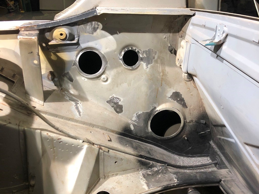
The rubber sleeve for the filter console fits the hole I cut nicely. Do the hard rubber/plastic insulation washers meet through the hole? In other words, do the mounting holes need to be large enough that the stepped mounting washers go through the holes?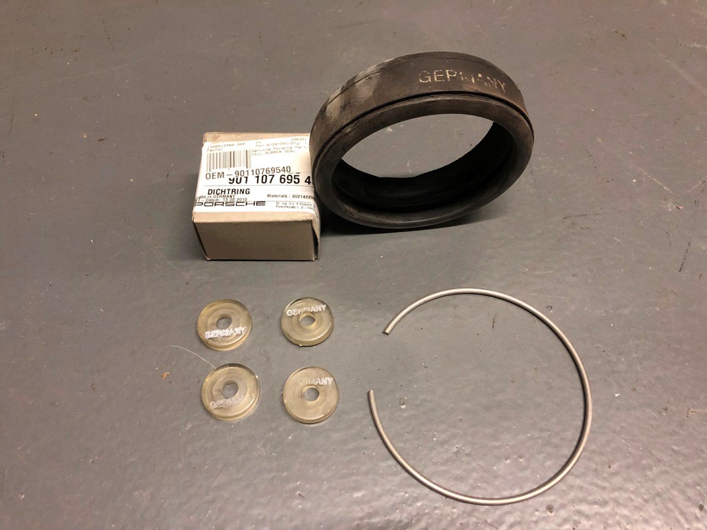
While I like the DW Design filler neck, I wish the screw-on cap looked more like the 914-6 oil fill cap. I may find a donor stock looking cap to modify. I found that the oil filler neck that I thought I had is actually from a 911 and doesn't properly fit the oil tank opening.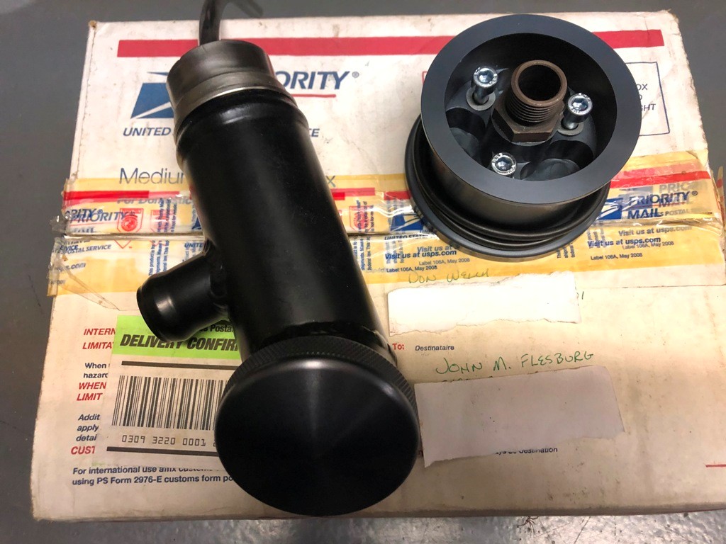
As I'm doing this, I'm wondering about how I will plumb this car. In the past, I've had front mount oil coolers and tanks. I've run the return line from the engine case up front to a thermostat then cooler then back to thermostat, then oil filter, then to tank. I've never plumbed in a pressure relief valve in the external oil cooler circuit. I've noticed that in all the 914-6 GT cars, a pressure relief valve in addition to a thermostat is used. I'm not 100% convinced that I really need the pressure relief valve, but why would they have put them in the GT cars? In air cooled 911 street cars, they simply put a thermostat in the lines leading to/from the front mounted coolers.
Any thoughts on the pressure relief valves plumbed into the GT cars? Anyone actually use a pressure relief valve in the lines to the external oil cooler?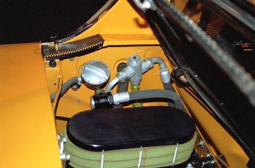
I have decided to relocate the engine lid release latch to the passenger side.
I'll keep plugging away at this.
Posted by: mepstein Dec 23 2020, 12:03 PM
Eric at PMB has the GT style pressure relief line in his car. It's not used often in these conversions and it's pretty pricy. The parts are similar to a 1969 911S. Reproductions are available but even they are a couple grand. for the whole setup.
I don't normally see the mounting holes drilled for the steps.
Posted by: mb911 Dec 23 2020, 03:42 PM
Eric at PMB has the GT style pressure relief line in his car. It's not used often in these conversions and it's pretty pricy. The parts are similar to a 1969 911S. Reproductions are available but even they are a couple grand. for the whole setup.
I don't normally see the mounting holes drilled for the steps.

I can source everything original but it really is waste of time
Posted by: John Dec 24 2020, 03:43 PM
The only reasoning I can come up with for the pressure relief valve would be if the bypass in either the filter console or the filter would fail, either popping the oil cooler or the oil filter. Most modern filters that I know of have a bypass built into them. Some of the racing filters will filter 100% oil all the time, but I'm not using one of those, and the filter console that I have doesn't even have a bypass installed and relies on the bypass of the filter itself. Not installing any of that makes sense to me, and makes plumbing far simpler. I was mainly looking for what others thought.
As far as the stepped washers go, I would assume that the one protruding would mount next to the tank, the recessed one would be in the engine bay covered with one of those large cup washers then a flat washer like on a 911.
I'll ask again, how many folks remove the 4-cyl engine mounts? While looking at where I think I'll end up running oil lines, those mounts might just be in the way, so that pretty much answers my own question.
Some days it's just tough to keep on-track and motivated. Too many distractions such as it looks like I need new o-rings for the injectors on that 2.7.
I'm still looking for those large cup washers that I swear I bought once upon a time...
Posted by: mepstein Dec 24 2020, 04:06 PM
I recently sent Ben an oil filter console just like yours. No bypass valve, just open flow. Do you remember where you purchased yours?
I normally use the regular Porsche console. I remove the threaded metal fitting and use a very small C clamp to hold down the bypass spring so I can make sure it gets cleaned out inside. Then a couple drops of motor oil to make sure it stays functional.
Ben/MB911 is making new consoles based off the Porsche design so we won't have to search for good used ones.
I have one conversion with 914-4 motor mounts and one without. The one without looks cleaner and has more space for hoses but the other reason was the mounts were rusty so getting in back of them was necessary to clean up the corrosion.
Posted by: John Dec 26 2020, 09:28 PM
I recently sent Ben an oil filter console just like yours. No bypass valve, just open flow. Do you remember where you purchased yours?
I normally use the regular Porsche console. I remove the threaded metal fitting and use a very small C clamp to hold down the bypass spring so I can make sure it gets cleaned out inside. Then a couple drops of motor oil to make sure it stays functional.
Ben/MB911 is making new consoles based off the Porsche design so we won't have to search for good used ones.
I have one conversion with 914-4 motor mounts and one without. The one without looks cleaner and has more space for hoses but the other reason was the mounts were rusty so getting in back of them was necessary to clean up the corrosion.
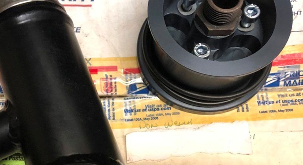
I think the filler neck and the filter console both came from Don Welch
I remember now why I was reluctant to remove the 4-cyl mounts, such a pain in the butt, but I'm glad I did as this is the first rust I've found, but it was just surface rust. I plan on welding in that piece of one of the old chassis stiffening kits now that the old engine mount is removed. Not sure it's really needed, but while I am in there...
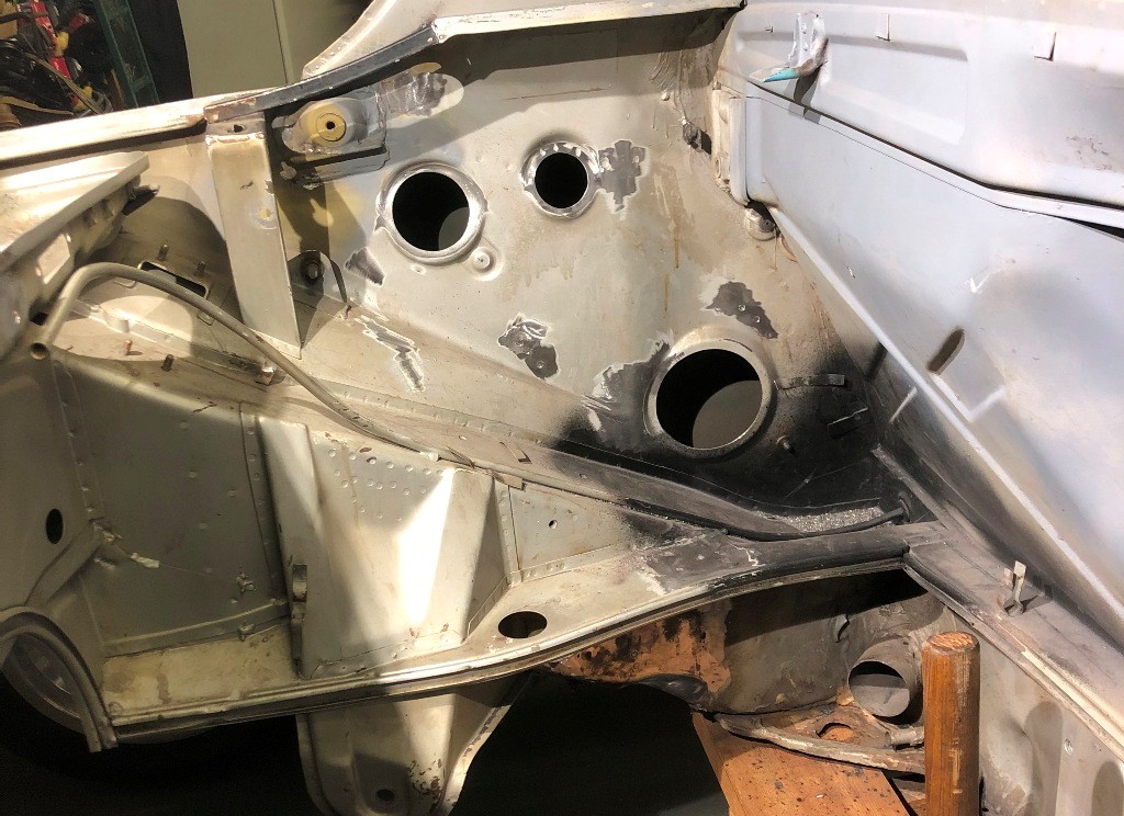
I guess now I must do the other side. Once it's done, I'll be glad I did as it is cleaner that way.
Powered by Invision Power Board (http://www.invisionboard.com)
© Invision Power Services (http://www.invisionpower.com)