Printable Version of Topic
Click here to view this topic in its original format
914World.com _ 914World Garage _ V8 Project Update
Posted by: FL 000 Oct 22 2019, 08:38 PM
Hi World, I am moving on to the next phase of my project, and have enough things planned that I will call it phase 2. Hopefully this thread will motivate me to see it through quicker, and maybe help someone else at the same time.
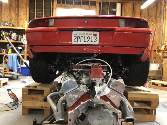
Phase 1 was my 7 year adventure taking a banged up 73 roller and installing a SBC, renegade kit, and Sheridan body kit. Here is basically what it looks like now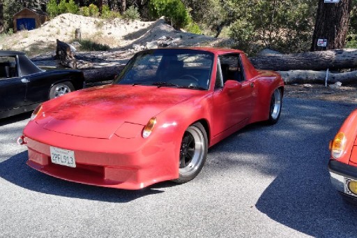
Had fun driving it for a summer and a winter, then realized I am ready to start the next round of upgrades. The list in no particular order and consists of:
Heat and a/c
Audi 01E install
Fuel injection
Boxster brakes
Fix passenger door gap
Time and money varies, so no timeline for when it will get done, but my wife's 62 Lincoln is next in line so I do have some encouragement to finish!
Posted by: FL 000 Oct 22 2019, 08:52 PM
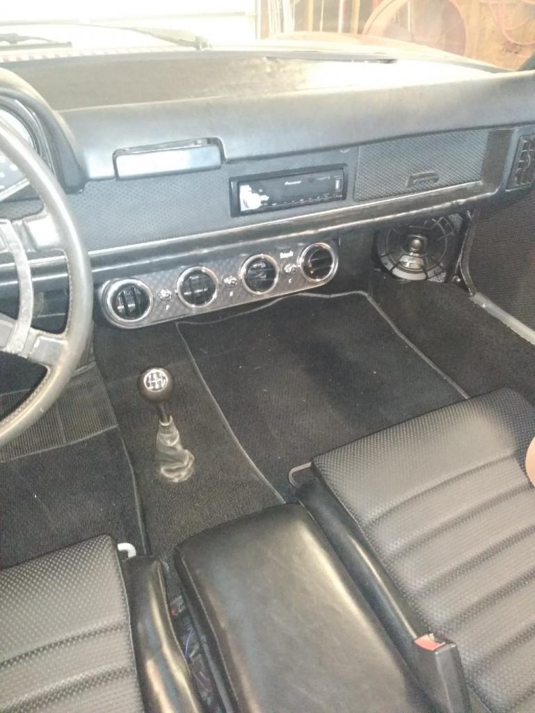
After driving it one year I quickly realized I am getting too old to enjoy it living in the desert without heat and a/c. I just finished the under dash blower unit install with heat, and to make room for the a/c compressor I decided to switch from a mechanical to electric water pump.
I went with the Vintage Air Heritage series under dash unit. Fits, and puts out plenty of air. 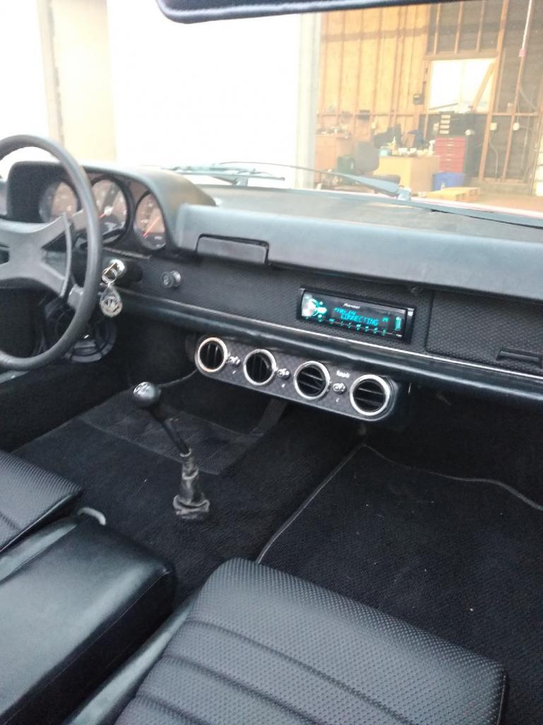
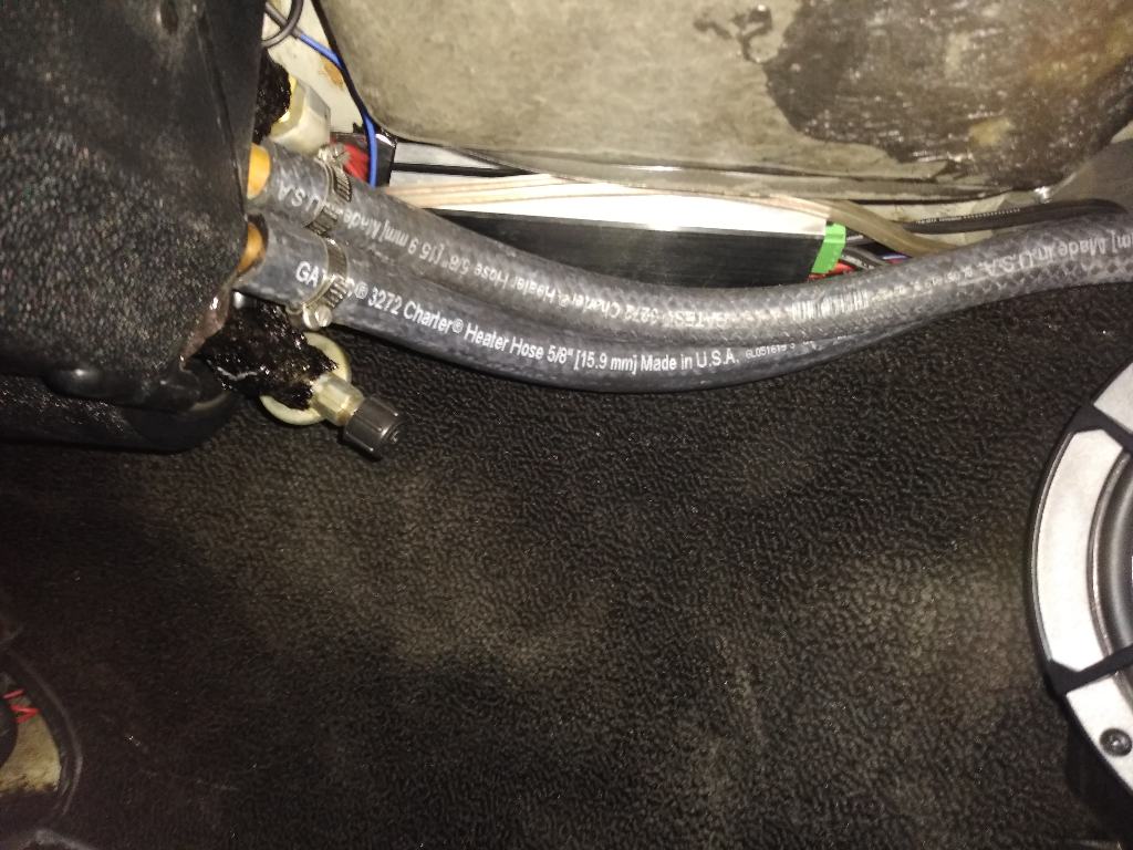
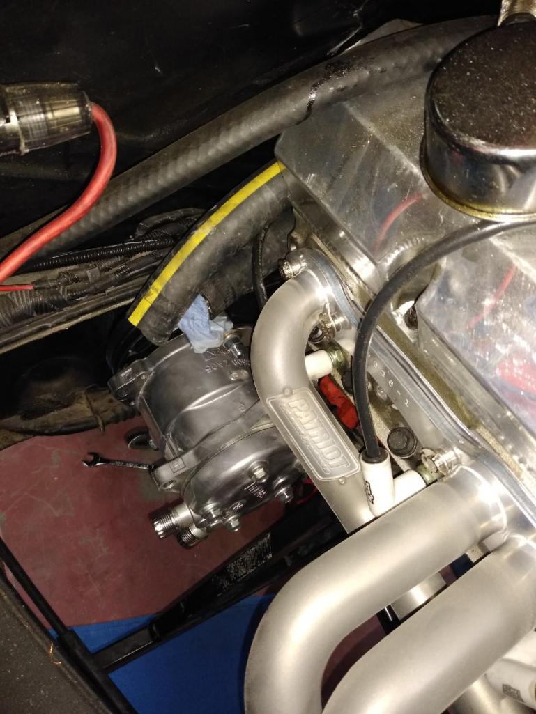
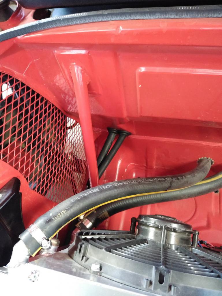
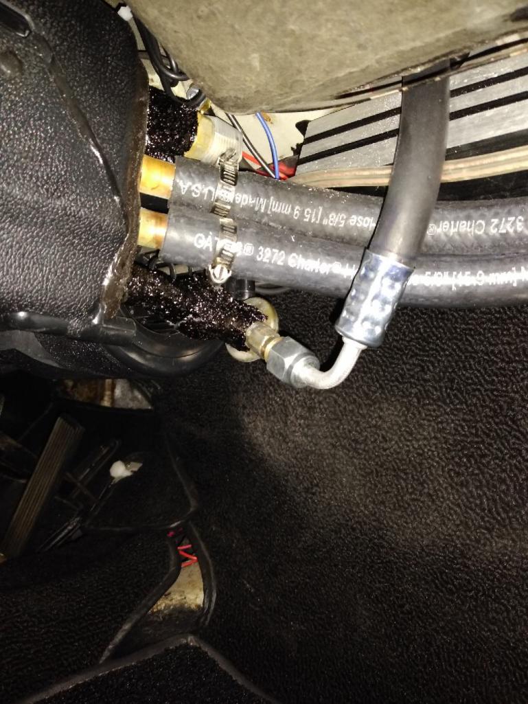
I went back and forth on where to pull the water from, and eventually settled on running the lines through the passenger long. 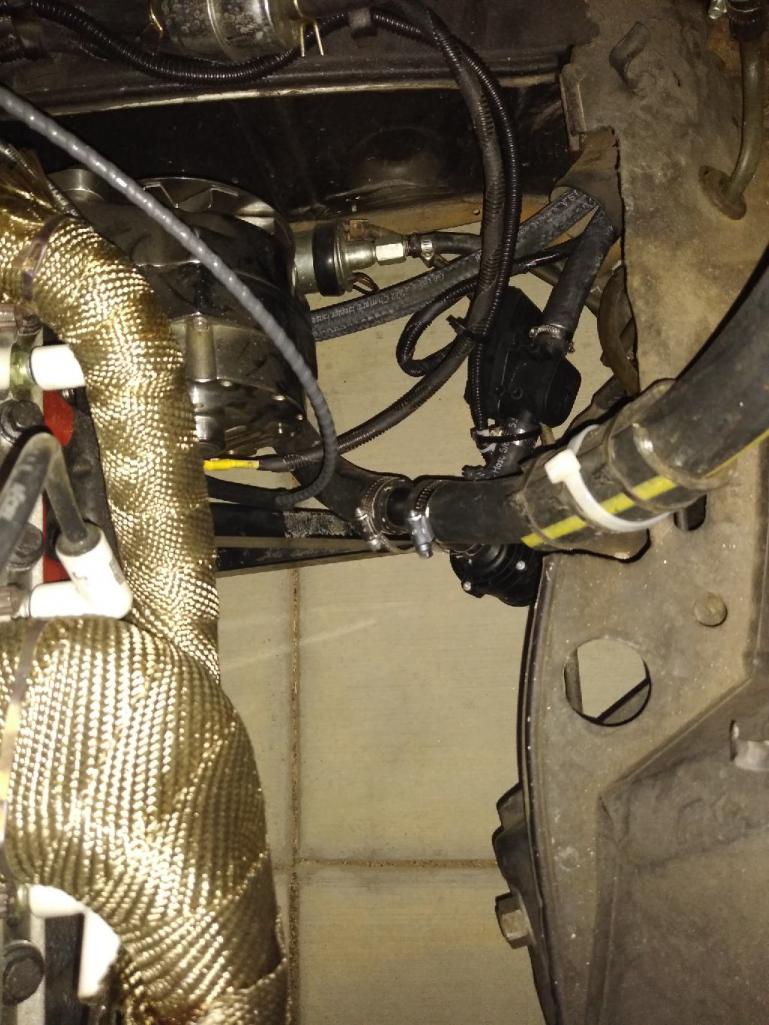
For pic above, take note of the 2 black components connected to the heater hose. The first one, closest to the long is the heater control valve, and the next one partially hidden behind the radiator hose is a booster pump; more to come on that. 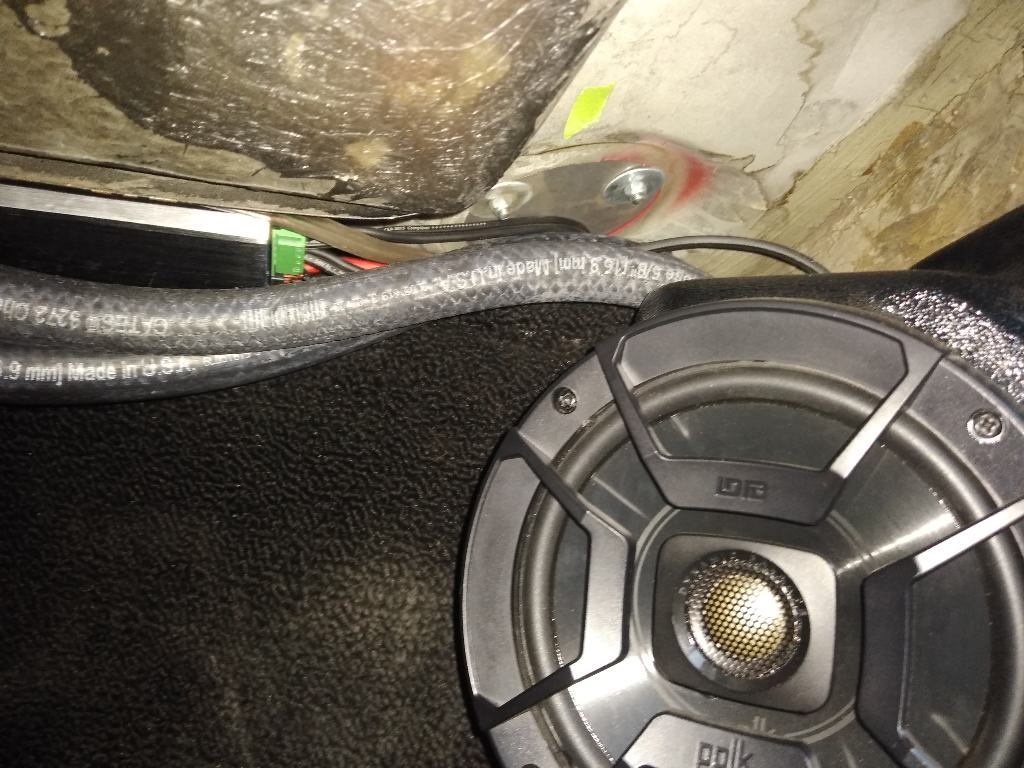
Posted by: FL 000 Oct 22 2019, 09:29 PM
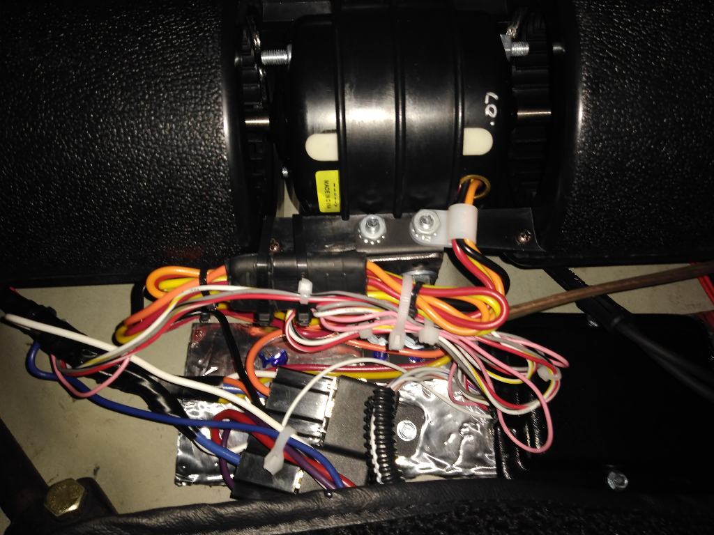
I know there are a number of electric water pumps on the market, but the Davies Craig caught my eye and is the one I went with. Pretty slick little unit that uses pulse wave modulation (PWM) to hit the target temp, which should help on the efficiency side. It also has as a control module that allows you to set your target temp, and control the radiator fans. Set it and forget it in theory. Here it is installed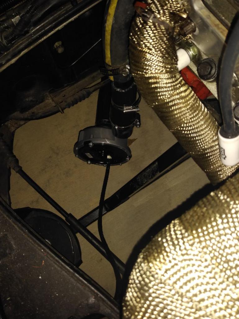
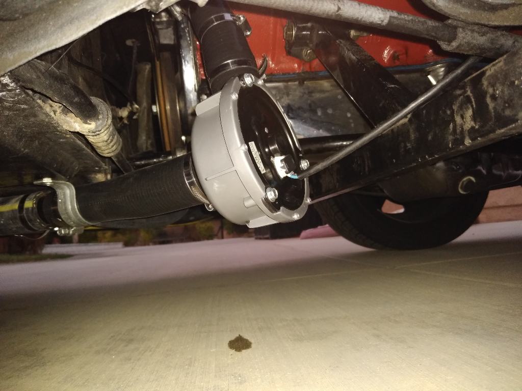
Yes that is a drop of water below it, yes it drives me nuts, and yes it will be fixed 
The pump looks lower then it really is compared to the engine bar, but I am going to secure it with a mount higher to be safe.
I was pretty proud of these adapters I made, even though they don't look all that impressive! The tube was too thick to put a DIY bead in, so I welded a bead around it. Seems to be sealing good so far. 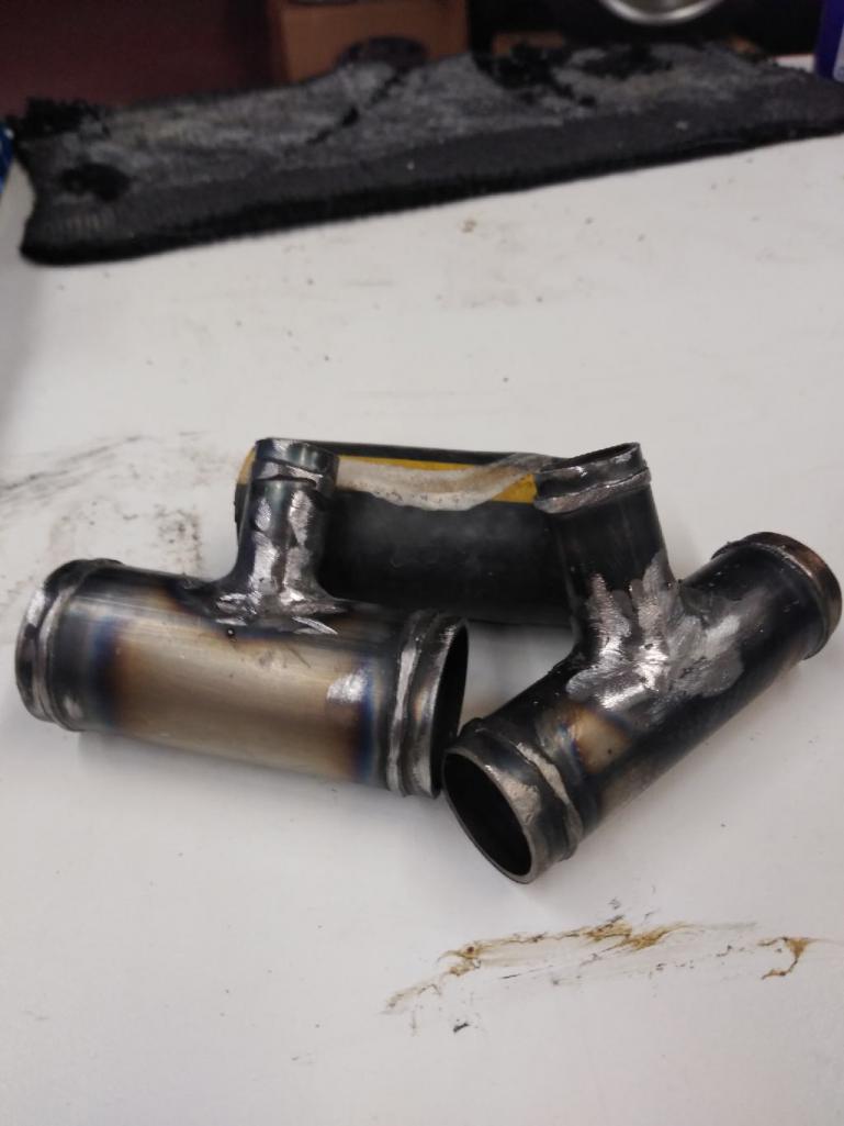
As I mentioned the waterpump uses PWM, which basically means cycling between off and on. For DC motors that is a better approach then say trying to control the RPM with varying voltage.
Because of this I was concerned my heater core would not see a consistent flow of hot water through it, and consequently may lead to inconsistent heat flowing out of the blower. Probably wouldn't have mattered, but I am a bit anal by nature so I decided to account for it.
I installed the booster pump shown in the previous post, and added an Arduino UNO to control it. I tapped into the potentiometer wire from the heater valve, and the more you turn the heat knob up the more the booster pump flows. This also seems to be working well.
Posted by: djway Oct 22 2019, 09:38 PM

I know there are a number of electric water pumps on the market, but the Davies Craig caught my eye and is the one I went with. Pretty slick little unit that uses pulse wave modulation (PWM) to hit the target temp, which should help on the efficiency side. It also has as a control module that allows you to set your target temp, and control the radiator fans. Set it and forget it in theory. Here it is installed
Yes that is a drop of water below it, yes it drives me nuts, and yes it will be fixed
The pump looks lower then it really is compared to the engine bar, but I am going to secure it with a mount higher to be safe.
I was pretty proud of these adapters I made, even though they don't look all that impressive! The tube was too thick to put a DIY bead in, so I welded a bead around it. Seems to be sealing good so far.
As I mentioned the waterpump uses PWM, which basically means cycling between off and on. For DC motors that is a better approach then say trying to control the RPM with varying voltage.
Because of this I was concerned my heater core would not see a consistent flow of hot water through it, and consequently may lead to inconsistent heat flowing out of the blower. Probably wouldn't have mattered, but I am a bit anal by nature so I decided to account for it.
I installed the booster pump shown in the previous post, and added an Arduino UNO to control it. I tapped into the potentiometer wire from the heater valve, and the more you turn the heat knob up the more the booster pump flows. This also seems to be working well.
Can you provide more detail on the booster pump for the electrically impaired


Posted by: FL 000 Oct 22 2019, 09:44 PM
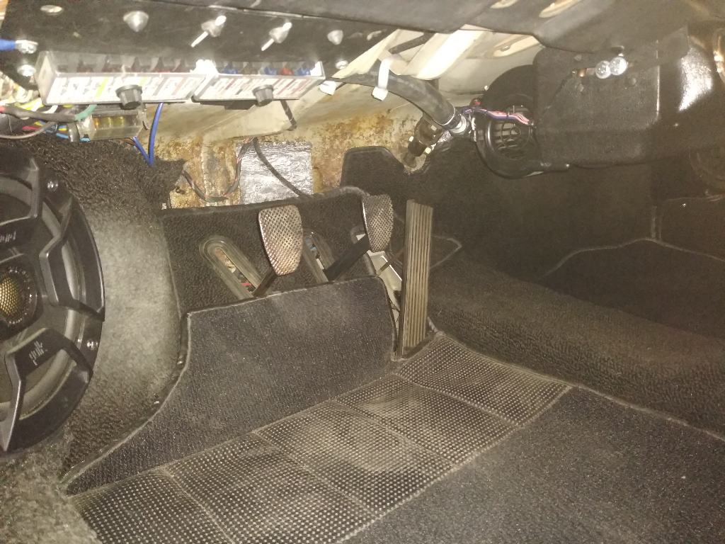
I know these cars are small, and was reminded of that many times on this project trying to add all the components, running wire and keeping it out of sight. I know there is not much room under and behind the seats, but turns out it was one of my better options. I didn't want to overload my fuse panel, so I added a power distribution block for positive and negative cables runs under the seat. Leaves some room for growth too (no idea whatelse I made decide to add).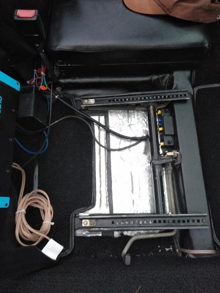
(Above) The small black box under the bass box houses my Arduino, a motor shield, and a few other components for the booster pump control. 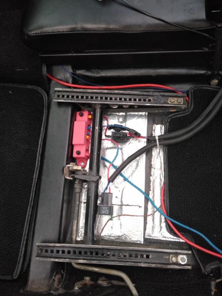
(Above) Wires for blower tucked up out of the way behind it.
Posted by: FL 000 Oct 22 2019, 10:03 PM
[quote name='djway' date='Oct 22 2019, 08:38 PM' post='2756568']
[/quote]
Can you provide more detail on the booster pump for the electrically impaired
[/quote]
Something tells me I butchered the quote...
Sure, I'll try. In a car with a mechanical water pump there is constant pressure in the coolant system, including the heater lines. When you adjust your heat setting in tbe cabin it is typically opening a valve on the heater hose to allow coolant to flow through your heater core.
With my water pump using pulse wave modulation, it may be on for 10 seconds, off for 20, on for 10, off for 20 and so on. So if I turn my heater to full hot, which opens the valve completely, it would not gauruntee that water was constantly flowing through my heater core.
So the little booster pump I have is a simple 12 volt pump that flows about 4-5 gallons per minute at max capacity. It works independent of the water pump, and is controlled by the heat setting on the blower unit in the cabin. Turns out I also use PWM to control the booster pump, but don't worry about that for now! Just know that when I select max heat the booster pump flows to it's max capacity, and as you lower the heat it slows down.
Hope that helps 
Posted by: FL 000 Oct 22 2019, 10:19 PM
Yep, I butchered the quote. Hopefully will live and learn as this progresses.
The heater is just in time for winter use, so a/c will be done before next summer. I usually completely underestimate how much work all this will be, but the a/c shouldn't be bad. I'll need to build a custom compressor mount (nothing fancy), then acquire the parts: compressor, lines, evaporator, a few odds and ends. I had the forethought to prerun the wires needed for the trinary switch and clutch, so that should save some time.
I would also like to attempt the Audi 01E trans install next year. Here is what my rebuilt unit looks like. I had 100 mm axle stubs installed to match up with my Renegade axles. 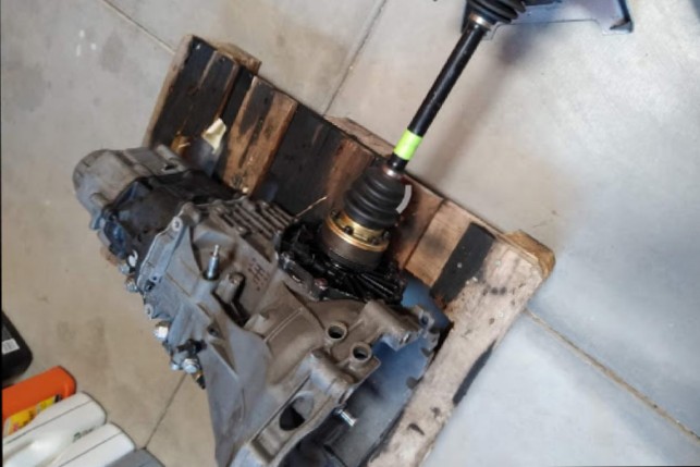
The challenges for me will be building the trans mounts, and the cable shifter linkage. I plan to use a Boxster S shifter and cables. I will definitely be asking for help when I get there.
Posted by: Andyrew Oct 22 2019, 11:16 PM
Love everything about this! Good choice on the pump.
Posted by: FL 000 Oct 23 2019, 04:53 PM
Love everything about this! Good choice on the pump.
Thanks Andrew - I am pretty sure I got the water pump idea from you
Posted by: Gearup Oct 24 2019, 04:23 PM
Removed
Posted by: djway Oct 26 2019, 12:08 AM
Thanks for the information.
Another question, can you get the hot water from up front near the radiator?
Posted by: jim_hoyland Oct 26 2019, 06:44 AM
Thanks for sharing, interesting to see your innovation; and, it was great seeing your car at the WCR in Monrovia. That is one cool car
Posted by: FL 000 Oct 26 2019, 12:38 PM
Thanks for the information.
Another question, can you get the hot water from up front near the radiator?
I would have rather tapped into the water lines up front but chose not to for a couple reasons. In the frunk area I felt like it would clutter it up too much with the lines, valve, and booster pump. I also didn't want to cut into that area unless I had to. If I had pre-planned this before I did the bodywork and paint I probably would have went that route.
It would have been great if I could have tapped in under the car near the steering rack, but space was an issue again. I plan to add a hydraulic clutch m/c soon and need to save some room in that area.
Posted by: FL 000 Oct 26 2019, 12:43 PM
Thanks for sharing, interesting to see your innovation; and, it was great seeing your car at the WCR in Monrovia. That is one cool car
Thanks Jim, it was great meeting you at WCR this year; I dig your car too!
Posted by: jb6000 Oct 27 2019, 09:27 AM
I am not too far from you and have a sbc 914 project.
I have a OE1 and a Boxster S trans. I just bought the Renegade trans mount for the Boxster Trans.
Posted by: FL 000 Oct 27 2019, 09:01 PM
I am not too far from you and have a sbc 914 project.
I have a OE1 and a Boxster S trans. I just bought the Renegade trans mount for the Boxster Trans.
I have been following you build, looks like a good project! Luckily you are ahead of me on the trans so I am sure I will learn some useful things from you.
Posted by: FL 000 Mar 29 2020, 09:49 PM
Heat worked great this winter and I got to drive a bunch more than last year. Finally got started on the air conditioning this weekend. These are some of the parts I have to work with: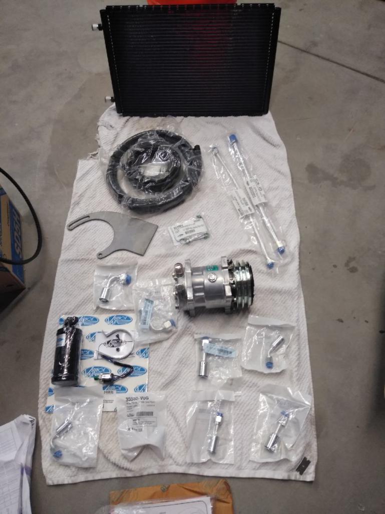
My Renegade setup has the double v-belt crank pulley to drive the alternator and water pump. Both grooves are for 13/32" belts. The AC compressor I got has a (double) v-belt groove pulley made for 17/32" belts. I researched sizes the best I could and decided a 13/32" belt should work. Was happy to see it doesn't bottom out in the groove.
Posted by: FL 000 Mar 29 2020, 10:08 PM
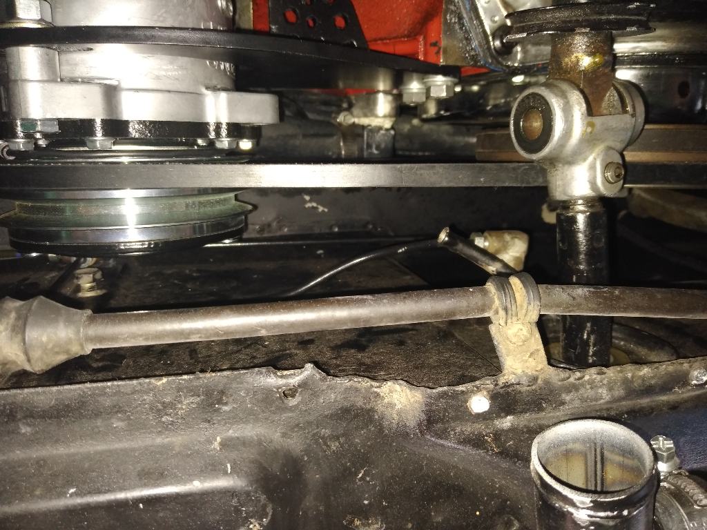
I made a template for my brackets, fit looked good, made the cuts and mounted the compressor. Was happy with the placement and then decided to put on an old belt to see what size I may need... the shift rod was in the way . It's always something right?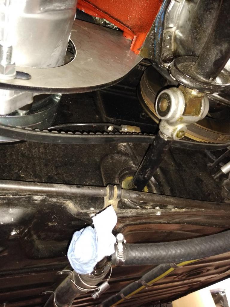
All was not lost since I had another bracket, and one will be cut down substantially for the rear brace. Second attempt made everything fit well, and the compromise was moving the compressor closer to the header pipe than I would have chosen. There is a few inches clearance so I am going to call that good; time will tell. 
Posted by: Mueller Mar 29 2020, 11:06 PM
Looks like a fun project, will be watching for sure.
Posted by: Daryl32 Mar 29 2020, 11:16 PM
Very COOL!!
I got John to go with the Davis Craig system also for his 350 swap.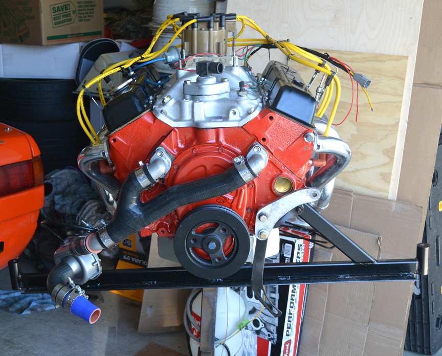
Posted by: FL 000 Mar 30 2020, 06:58 AM
Very COOL!!
I got John to go with the Davis Craig system also for his 350 swap.
I think you will be happy with this system. I don't have a lot of miles on mine yet but so far so good.
Posted by: FL 000 Mar 30 2020, 10:38 PM
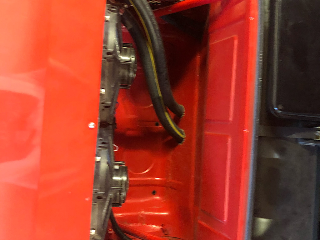
I got alittle more done tonight routing the suction and discharge hose through the driver long. The larger suction hose is going to enter the cabin on the horizontal shelf behind the gas tank; directly above the evap. The discharge hose is going behind the tank, down and under it out the front bulk head to the condenser.
Putting fittings on this under the car will be a pain in the ass.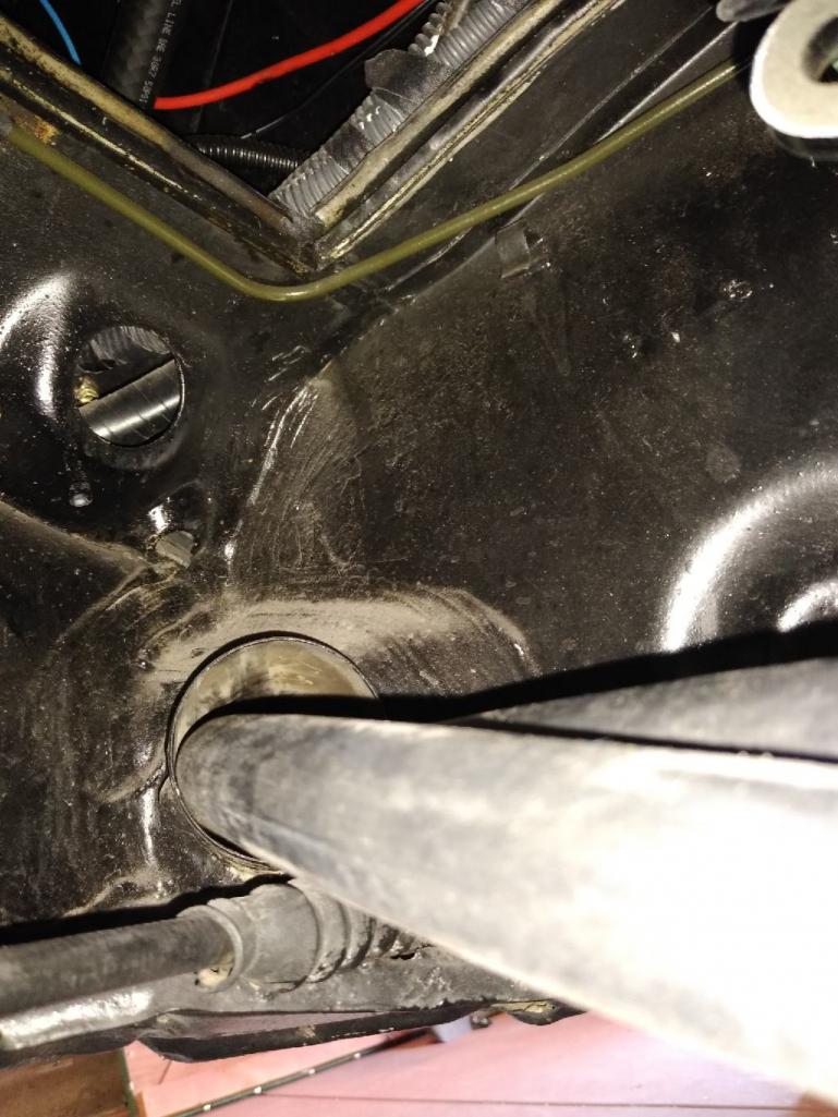
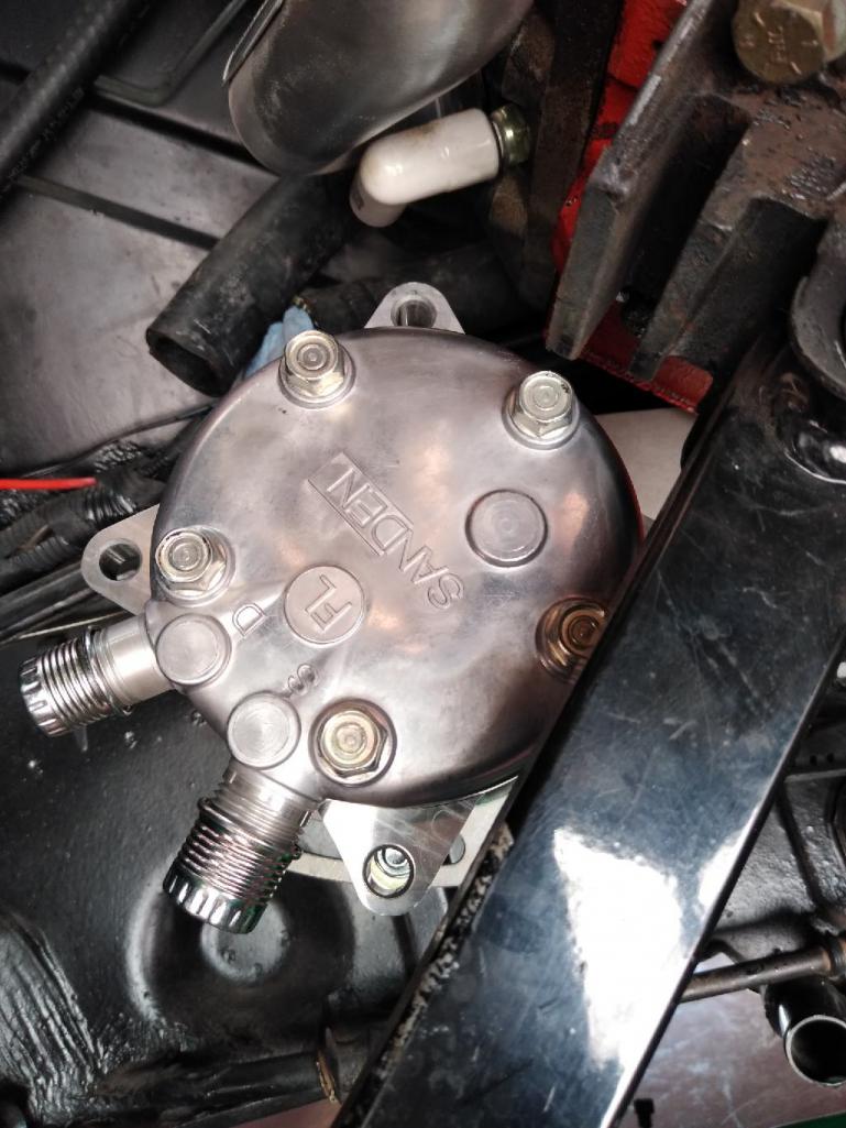
Unfortunately this side exit head on the compressor isn't going to work. Sanden recommends not rotating the fittings past 90 degrees. Tempted as I am to try it my guess is oil will pour out when I install the fittings, or may make the vacuum and fill process difficult. Rotating it 90 degrees clockwise points the fittings right at the exhaust. I decided to swap out the head for a rear exit setup which should put the fittings in a better place.
Posted by: whitetwinturbo Apr 5 2020, 08:24 PM
.....................watching this .......... really interesting way to deal with AC and I'm thinking how it could work for my v8 too 
Posted by: FL 000 Apr 18 2020, 09:09 PM
Got some more work done the past couple days. Condenser is plumbed and wiring for trinary switch almost complete. I used a couple aluminum tubes for simplicity and to help where the rubber hose might have kinked. 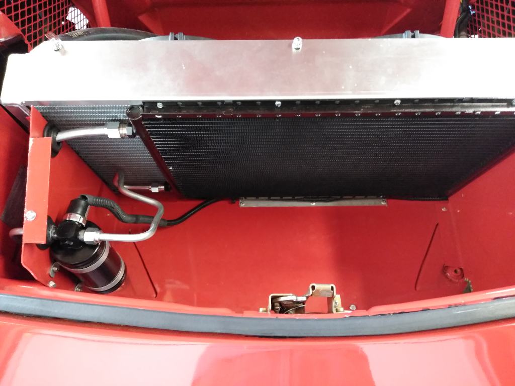
Everything is a compromise right? I decided to go with the smaller condenser for a couple reasons. I didn't like the options I had for mounting the receiver/drier outside the current location; a lot of heat behind radiator and no room inside the cabin. The condenser is a high efficiency one, so not overly concerned with its ability to cool the small interior.
I have heard of many people having issues keeping their V8 engines cool, and I have never had a problem. Hopefully this won't be the start of any 
Posted by: FL 000 Apr 18 2020, 09:15 PM
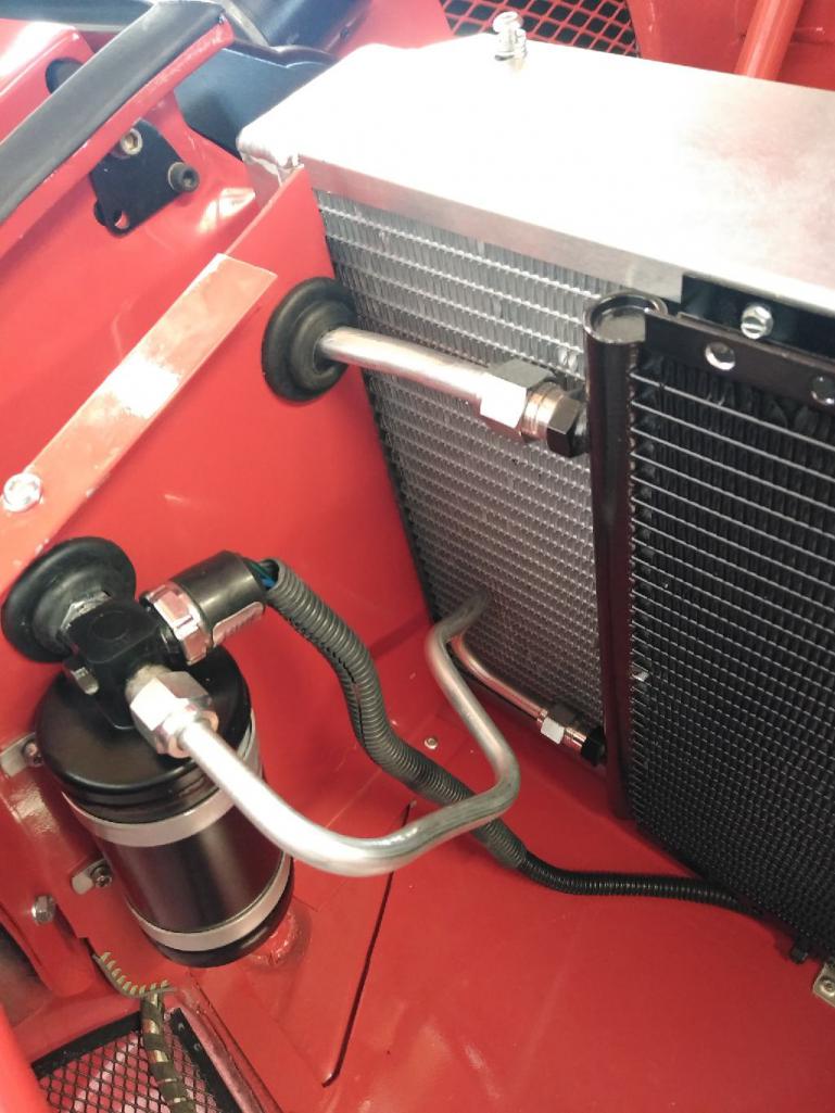
Condenser hoses go under and then up behind the tank. The #6 then goes down into the cab to connect to the evaporator. Pretty tight but kept everything tidy. 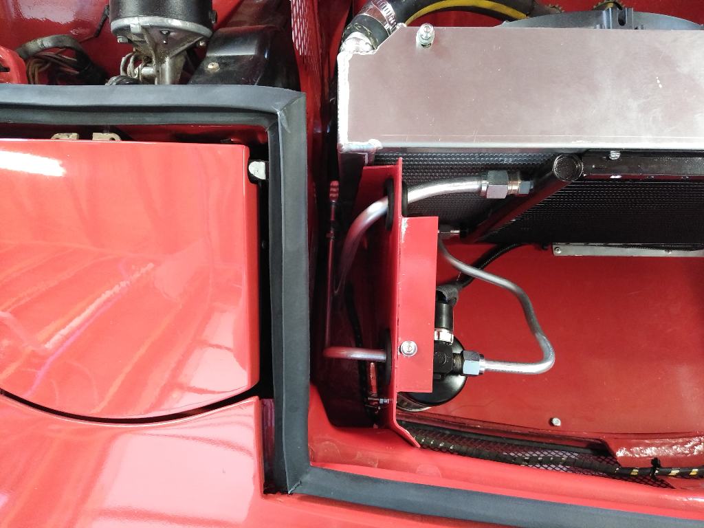
Posted by: FL 000 Apr 18 2020, 09:24 PM
Here's a pic of the hose going to the evap. It's high enough where your feet clear it when seated, but low enough that I am concerned someone my break it some point. I'll probably try to make a cover to give it some protection. 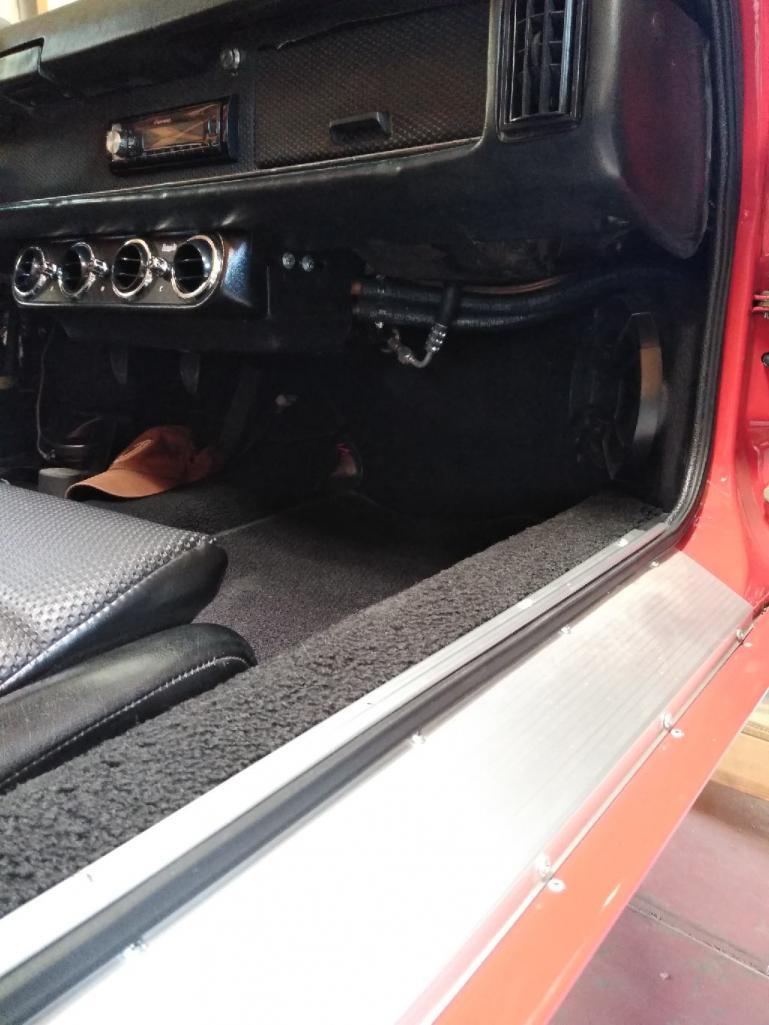
That's it for today. May be able to get the compressor mounted and final connections made tomorrow. ![yellowsleep[1].gif](style_emoticons/default/yellowsleep[1].gif)
Posted by: 914pipe Apr 18 2020, 09:42 PM
Very Nice!!!
Posted by: 914pipe Apr 18 2020, 09:42 PM
Very Nice!!!
Posted by: tygaboy Apr 18 2020, 10:53 PM
That's a tidy install! 
Posted by: FL 000 Apr 27 2020, 09:12 PM
Got some more work done the past couple weekends. The next step was getting the #10 suction hose connected to the back of the evaporator. I rerouted it from the heater channel exiting the long and under the dash. This reduced the number of holes to drill - more better. 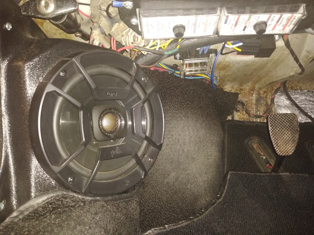
Posted by: FL 000 Apr 27 2020, 09:20 PM
Then it was working on the business end. Here is the Sanden compressor with the mount finished and the new back on it for the rear hose connections. 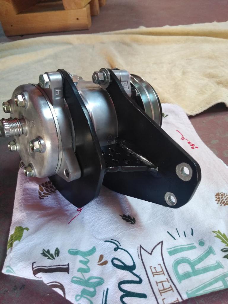
I realized after I painted it that the compressor needs to ground through the mount for the clutch, hence the attempt at removing paint in a circular fashion. This is a case of function over form 
Posted by: FL 000 Apr 27 2020, 09:26 PM
Crimping the hose connections was a bit of a pain under the car, but the engine bar made a nice mount for me to clamp the tool on so I could wrench it.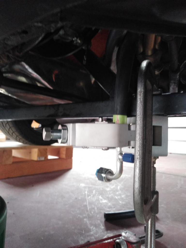
And here are a couple pics from above and below with everything connected.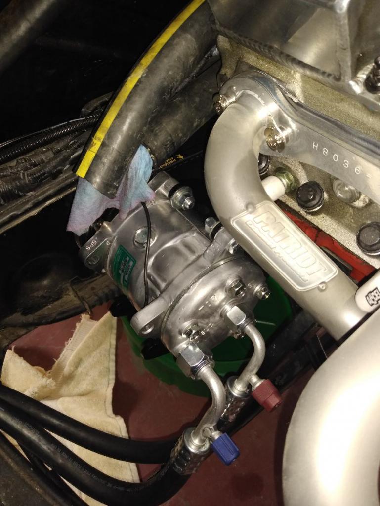
Posted by: FL 000 Apr 27 2020, 09:42 PM
After all that work I was definitely sweating the vacuum test. I took my time on everything but there are so many places a leak could exist. I bought a new hose kit from Harbor Freight (big spender) to replace my old one that had bad hoses. 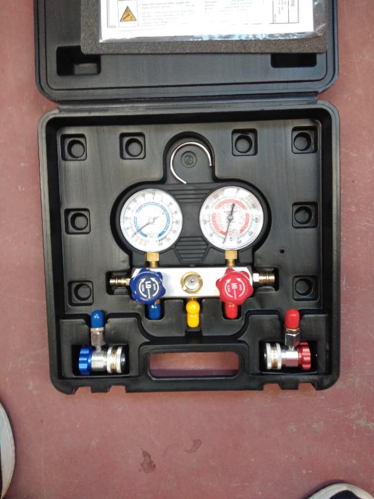
I connected and drew some vacuum, sealed the valve, turned off the pump, and watched the system slowly lose vacuum WTF. Walked away and slept on it for the night. The next day I thought maybe, just made be it was the HF hose kit and not all my custom work (cocky I know). After some tests sure enough the new quick disconnect couplers that attach to the high and low pressure ports were bad. Luckily my old ones still worked, so on they went and to my surprise it held pressure! Around 26 inches of vacuum after letting it rest for 45 minutes. 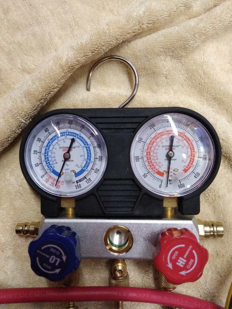
After I get the water pump reinstalled I will be able to fill it and enjoy some cool air. Just in time as it got into the 90's this past weekend.
Posted by: 76-914 Apr 28 2020, 11:19 AM
Your going to love the AC. One of the best upgrades a man can do.
Posted by: burton73 Apr 28 2020, 02:26 PM
I like the way you v8 car is coming along. 1st rate in my book
Bob B 
Posted by: FL 000 Apr 28 2020, 07:48 PM
Your going to love the AC. One of the best upgrades a man can do.
I have to thank you Kent for documenting your AC install - definitely helped me get through this.
Posted by: FL 000 May 22 2020, 04:28 PM
Been a crazy last few weeks with work and projects around the house. Found a few hours here and there to (mostly) finish the a/c install. But before we get to that I had these arrive recently: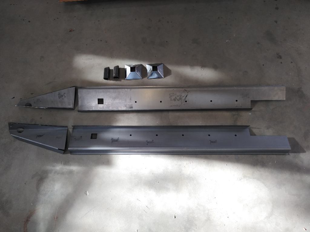
I am hoping they are the answer to my door gap nightmare.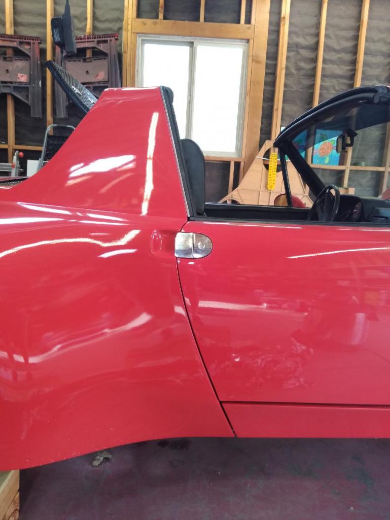
If interested you can look here for some background http://www.914world.com/bbs2/index.php?showtopic=326911&hl=
Ok back to the a/c. I decided to go a different route with the engine coolant lines. I had been running the Renegade setup which was fine, but I found some AN fittings that looked like they would cleanup the install. The pic below shows the old (bottom) to new setup.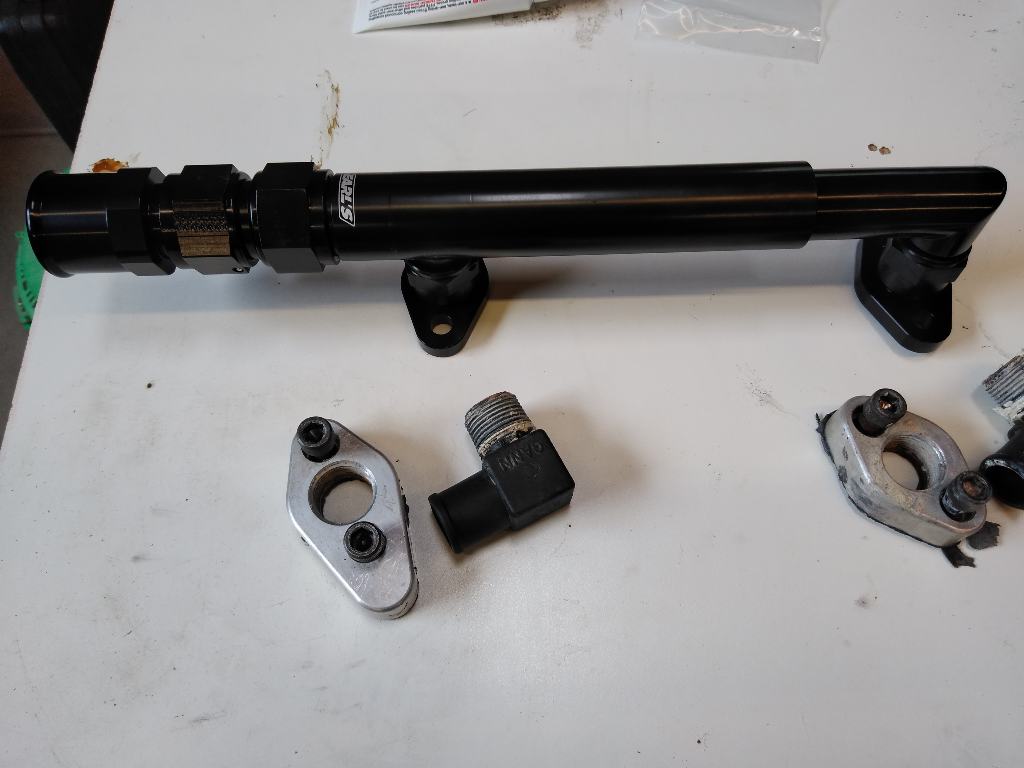
It was a pricey detour, and the verdict is still out if it was a good decision. It did clean up the install, so as long as leaks don't develop I should be good. The new pipe was running on top of the main wire harness, so I ran a thermal blanket around the wire to protect it.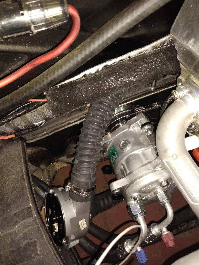
Posted by: FL 000 May 22 2020, 04:40 PM
I added the freon and after a couple failed attempts getting my radiator hoses to seal properly I was able to test drive it yesterday. It is always a good feeling to get back on the road after some down time, however, I want to get a few trips out of the way before I fully trust that it will be reliable.
Two things I need to address, one being the alternator capacity and the other the engine temp. The car struggled to stay at the correct operating temp, and that was with the fans running almost full-time. I have a hunch there is still some air in the system, so hopefully after a few iterations I can get it fully bled which should get the temps back under control. If not then putting that hot a/c condenser directly in front of my radiator might have tipped the scales.
My 80 amp alternator seems to struggle to keep up with the radiator fans, blower motor, water pump, fuel pump, amps, etc, etc. New 140 amp alternator on its way and will hopefully get that installed this weekend.
Posted by: ValcoOscar May 22 2020, 05:06 PM
Very nice Josh. Clean install!!!
Now we can say you and Kent have some of the COOLEST 914's around.
I'm envious of you two.
Oscar
Posted by: FL 000 Aug 19 2020, 03:42 PM
Been a few months since I have done much work but I have been having fun driving! A/C seems to be working well but may need a few more tweaks down the road. Went on a long road trip last month and the cab got heat soaked; AC was still blowing cold but it was getting hot inside. If anyone has any ideas I am open ears, and I am thinking a couple of things may help:
1) I need to make a panel to seal off the opening between my radiator and forward bulkhead in front of the gas tank so the hot air only escapes through the cutouts by the tires. Relying on my fiberglass hood to do that job isn't working well, especially at speed when the increased pressure is pushing the hood up.
2) Additional thermo mat in the cab couldn't hurt. I have a decent amount on the floors, the front/rear firewall, and inside the doors. I forgot to put some under the targa top.
Posted by: FL 000 Aug 19 2020, 04:44 PM
Next up is installing the Brad Mayeur 914LTD Long kit to fix my passenger door gap. It has been very hot here the past couple weeks (in the desert, go figure) so work is going slower than I would like. So far I removed the door sill supports and the jack points and rough fitted the stiffners in place.
Getting to this point wasn't too bad but the jack points proved to be a delicate operation. With the Sheridan kit (soon to be known as 914rubber kit?!) in place, I had limited access to remove them. An extended reach disk grinder, a die grinder, and sawsall made it happen. A small blemish here or there but in general I didn't butcher anything too bad. 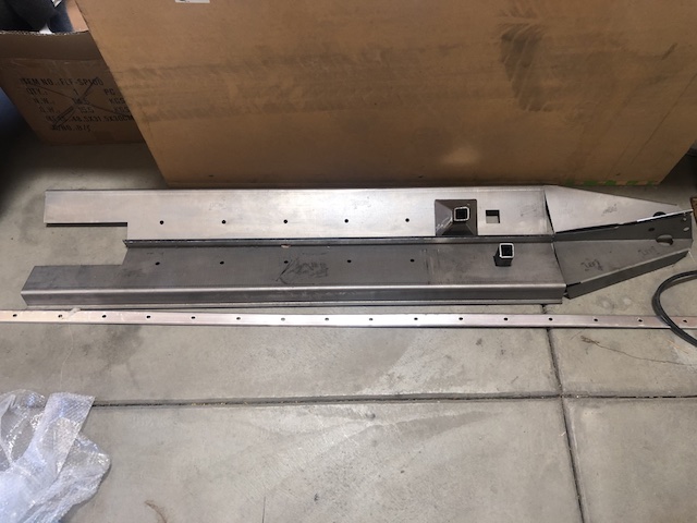
Posted by: FL 000 Aug 19 2020, 04:49 PM
I know many of you have installed these before. The instructions read fairly straight forward, but I am wondering if I need to allow the gap to be a smidgeon large when welding it in so the gap settles to the right amount when the full weight is back on the wheels? I don't want to overthink it, but this seems like a case where I only get one shot to make it right.
Posted by: 914forme Aug 19 2020, 06:19 PM
Okay this is how I did it on my auto-X car.
I supported the middle let both ends droop. That opened up the gap, I then took my Porta Power and used it to get the gaps where I wanted them. One end up on the Roll bar, top off, and the other in the foot well. Had a board down there to spread the load. And just pumped it until I got the gap I wanted.
I went to https://www.harborfreight.com/8-inch-industrial-c-clamps-39610.html, I used three of them per log. Screws on the outside will clear the threshold and get back under to hold the log in place. Clamp it to and take your time on the welding, I also did the engmann kit at the same time, https://maddogsmotorsports.com/914-chassis-stiffening.
Hope that helps
Posted by: 76-914 Aug 19 2020, 07:08 PM
Been a few months since I have done much work but I have been having fun driving! A/C seems to be working well but may need a few more tweaks down the road. Went on a long road trip last month and the cab got heat soaked; AC was still blowing cold but it was getting hot inside. If anyone has any ideas I am open ears, and I am thinking a couple of things may help:
1) I need to make a panel to seal off the opening between my radiator and forward bulkhead in front of the gas tank so the hot air only escapes through the cutouts by the tires. Relying on my fiberglass hood to do that job isn't working well, especially at speed when the increased pressure is pushing the hood up.
2) Additional thermo mat in the cab couldn't hurt. I have a decent amount on the floors, the front/rear firewall, and inside the doors. I forgot to put some under the targa top.
Oh yes. BTDT. In my case the tank would get so hot that the gas, being pre-heated, would vapor lock after 45 minutes or so unless it was cold outside. I chased it for months before realizing I had created the problem. I ran 4500 miles w/o a problem until I changed radiators in anticipation of a future AC install. And along with the larger radiator I increase the opening in the grille thus violating the 20% rule which I had adhered to during the original conversion. My intake allowed too much air into the trunk and the excess would escape over the gas tank and into the cabin. What seems like heat soak in the cabin happens when the heated air from the radiator is passing over a tank full of hot gasoline. You'll need to balance that out by increasing your fender well outlets or ducting your intake air out the fender wells. If increasing the fender well cutouts doesn't work you need to get a pressure differential gage to check that the there is negative side (the area where the wheels are) and a positive area in the trunk. I've read comments about flares interfering with this but cannot confirm as there just isn't much reliable info out there. I can say that every conversion I've been in has some "overflow" of warm air into the cabin. If you duct and it is sealed you will have 0% overflow. This was the best thing I ever did to mine. The AC was the 2nd best improvement. I choose aluminum because I had a little experience with it and all the tools to do so. Otherwise, I might have chosen some flexible AC/Heat duct or canvas. Canvas being the more durable of the two and less likely to tear.
Posted by: FL 000 Aug 20 2020, 05:55 PM
Okay this is how I did it on my auto-X car.
I supported the middle let both ends droop. That opened up the gap, I then took my Porta Power and used it to get the gaps where I wanted them. One end up on the Roll bar, top off, and the other in the foot well. Had a board down there to spread the load. And just pumped it until I got the gap I wanted.
I went to https://www.harborfreight.com/8-inch-industrial-c-clamps-39610.html, I used three of them per log. Screws on the outside will clear the threshold and get back under to hold the log in place. Clamp it to and take your time on the welding, I also did the engmann kit at the same time, https://maddogsmotorsports.com/914-chassis-stiffening.
Hope that helps
Thanks for the additional info Stephen. Based on your method it sounds like I don't need to account for additional movement once I go from having it supported in the air to back on the wheels.
My gap opens to the desired amount just by jacking up the side of the car, so I will support it in the middle (front and rear) and use a jack or stand under the trans to maintain the gap.
Just picked up 3 huge C-clamps and an F-clamp to boot so hopefully I can move to the next step soon.
Posted by: FL 000 Aug 20 2020, 06:44 PM
Been a few months since I have done much work but I have been having fun driving! A/C seems to be working well but may need a few more tweaks down the road. Went on a long road trip last month and the cab got heat soaked; AC was still blowing cold but it was getting hot inside. If anyone has any ideas I am open ears, and I am thinking a couple of things may help:
1) I need to make a panel to seal off the opening between my radiator and forward bulkhead in front of the gas tank so the hot air only escapes through the cutouts by the tires. Relying on my fiberglass hood to do that job isn't working well, especially at speed when the increased pressure is pushing the hood up.
2) Additional thermo mat in the cab couldn't hurt. I have a decent amount on the floors, the front/rear firewall, and inside the doors. I forgot to put some under the targa top.
Oh yes. BTDT. In my case the tank would get so hot that the gas, being pre-heated, would vapor lock after 45 minutes or so unless it was cold outside. I chased it for months before realizing I had created the problem. I ran 4500 miles w/o a problem until I changed radiators in anticipation of a future AC install. And along with the larger radiator I increase the opening in the grille thus violating the 20% rule which I had adhered to during the original conversion. My intake allowed too much air into the trunk and the excess would escape over the gas tank and into the cabin. What seems like heat soak in the cabin happens when the heated air from the radiator is passing over a tank full of hot gasoline. You'll need to balance that out by increasing your fender well outlets or ducting your intake air out the fender wells. If increasing the fender well cutouts doesn't work you need to get a pressure differential gage to check that the there is negative side (the area where the wheels are) and a positive area in the trunk. I've read comments about flares interfering with this but cannot confirm as there just isn't much reliable info out there. I can say that every conversion I've been in has some "overflow" of warm air into the cabin. If you duct and it is sealed you will have 0% overflow. This was the best thing I ever did to mine. The AC was the 2nd best improvement. I choose aluminum because I had a little experience with it and all the tools to do so. Otherwise, I might have chosen some flexible AC/Heat duct or canvas. Canvas being the more durable of the two and less likely to tear.
Alright, Kent I think I have some work to do. Luckily I have not had a problem with vapor lock to date. I hadn't thought about measuring the pressure differential and that could potentially be a fun project. With all the body work done I will try the duct option first and see if that makes any improvements. Summer is getting close to over so maybe by next year I can fit that into the list of things to do!
Posted by: 914forme Aug 20 2020, 06:48 PM
Make sure you measure everything, and they stay there once you jack it and support it. This is a measure 20 times, do a small weld, and hen take more measurements.
Posted by: theer Aug 20 2020, 08:24 PM
Been a few months since I have done much work but I have been having fun driving! A/C seems to be working well but may need a few more tweaks down the road. Went on a long road trip last month and the cab got heat soaked; AC was still blowing cold but it was getting hot inside. If anyone has any ideas I am open ears, and I am thinking a couple of things may help:
1) I need to make a panel to seal off the opening between my radiator and forward bulkhead in front of the gas tank so the hot air only escapes through the cutouts by the tires. Relying on my fiberglass hood to do that job isn't working well, especially at speed when the increased pressure is pushing the hood up.
2) Additional thermo mat in the cab couldn't hurt. I have a decent amount on the floors, the front/rear firewall, and inside the doors. I forgot to put some under the targa top.
Oh yes. BTDT. In my case the tank would get so hot that the gas, being pre-heated, would vapor lock after 45 minutes or so unless it was cold outside. I chased it for months before realizing I had created the problem. I ran 4500 miles w/o a problem until I changed radiators in anticipation of a future AC install. And along with the larger radiator I increase the opening in the grille thus violating the 20% rule which I had adhered to during the original conversion. My intake allowed too much air into the trunk and the excess would escape over the gas tank and into the cabin. What seems like heat soak in the cabin happens when the heated air from the radiator is passing over a tank full of hot gasoline. You'll need to balance that out by increasing your fender well outlets or ducting your intake air out the fender wells. If increasing the fender well cutouts doesn't work you need to get a pressure differential gage to check that the there is negative side (the area where the wheels are) and a positive area in the trunk. I've read comments about flares interfering with this but cannot confirm as there just isn't much reliable info out there. I can say that every conversion I've been in has some "overflow" of warm air into the cabin. If you duct and it is sealed you will have 0% overflow. This was the best thing I ever did to mine. The AC was the 2nd best improvement. I choose aluminum because I had a little experience with it and all the tools to do so. Otherwise, I might have chosen some flexible AC/Heat duct or canvas. Canvas being the more durable of the two and less likely to tear.
 I have the same issue on my Subie conversion. The bulkhead seal makes a big difference, if you can get it to seal. Also, make sure to close off all the original heat/fresh air holes. That’s how the hot air is getting in the cabin. I saw that You currently have an AC hose coming in through one, so that might be tricky. If you’ve taken out the original fresh air blower and diverter valves, you’ll have eight openings to block off- 4 on each side: a round opening by the fender wall where the hot air came from the stock motor; above it a smaller round hole for the side dash vents; oval hole where the diverter valves were mounted; And, the defroster openings. Maddog makes a kit to seal off all the openings except the defrosters. Without the air box installed, outside air will come though the cowl grill and into the cabin through all those, and any other, openings. I was surprised how much air gets in, even with the roof on and windows closed.
 Posted by: 76-914 Aug 20 2020, 09:24 PM
I my case blocking off all holes didn’t help much. My tank was too hot to touch with my bare hand for more than a few seconds. It radiated heat to the firewall itself. The firewall was hot to the touch as well. If your going to duck it then don’t worry about checking pressure differential. Ducking will eliminate the problem entirely.
Posted by: FL 000 Aug 29 2020, 02:31 PM
Appreciate the comments on how to keep the hot air out of the cabin. I am going to make sure all the original holes for the heater are sealed (have the block off kit installed but may have missed some). I’ll also duct it to force the air out the wheel well vents.
Back to the long support and question on this brace that supports the jack donut. I have a little ‘while I’m in there’ on my mind and thinking I might as well straighten it out if it isn’t too difficult. Is it just some spot welds around the perimeter or does the donut need to come off separate? I figure it will be easier to straighten out if it is removed. Thoughts? Maybe I should just leave it alone and press...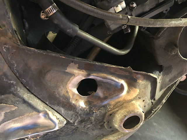
Posted by: 76-914 Aug 29 2020, 04:25 PM
Looks like the edge of the brace won't move much further. Maybe saw cut it leaving the spot welds in place. After the gap issue is resolved go back and seam weld the brace.
Posted by: dakotaewing Aug 29 2020, 07:01 PM
When I added the Mayer kit for my car I bought a drill press and Quadrupled the number of holes for the roset welds. Consider having smaller C-clamps for the bottom crimp welds.
I have a bunch of pics on the install in my build page. And be advised that these will affect the fit of the rockers - more than a little bit...
Posted by: tygaboy Aug 29 2020, 07:42 PM
When I added the Mayer kit for my car I bought a drill press and Quadrupled the number of holes for the roset welds. Consider having smaller C-clamps for the bottom crimp welds.
I have a bunch of pics on the install in my build page. And be advised that these will affect the fit of the rockers - more than a little bit...
I had prepped a Mayer kit for my build and did the same thing. I ended up going a different way but did like the idea of more attachment points. Just remember that the only place the part contacts the long is on the long's raised ribs - unless you add a filler plate to close that gap.
Posted by: Matty900 Aug 30 2020, 10:01 PM
Been a few months since I have done much work but I have been having fun driving! A/C seems to be working well but may need a few more tweaks down the road. Went on a long road trip last month and the cab got heat soaked; AC was still blowing cold but it was getting hot inside. If anyone has any ideas I am open ears, and I am thinking a couple of things may help:
1) I need to make a panel to seal off the opening between my radiator and forward bulkhead in front of the gas tank so the hot air only escapes through the cutouts by the tires. Relying on my fiberglass hood to do that job isn't working well, especially at speed when the increased pressure is pushing the hood up.
2) Additional thermo mat in the cab couldn't hurt. I have a decent amount on the floors, the front/rear firewall, and inside the doors. I forgot to put some under the targa top.
I am starting to try and figure this out for my V8 car and I am curious about the hood and the pressure. I am thinking of having a decorative cover made for the firewall and gas tank and have some thermal protection added in it. Can you post some photos of the inside of the fiberglass hood and let me know where it is pushing up?
Posted by: FL 000 Aug 31 2020, 07:24 PM
I am starting to try and figure this out for my V8 car and I am curious about the hood and the pressure. I am thinking of having a decorative cover made for the firewall and gas tank and have some thermal protection added in it. Can you post some photos of the inside of the fiberglass hood and let me know where it is pushing up?
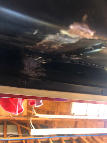
Sure thing @http://www.914world.com/bbs2/index.php?showuser=18454 , I have noticed while driving around the pressure forces the air up over the bulkhead in front of the gas tank. Fiberglass never fits as well as the stock steel hood right? So I realized during reassembly after paint that the factory bulkhead seal was too tall. Nothing a little trimming couldn’t fix, but yours my fit better with that in mind.
The channel running left/right is letting air through, and more at speed.
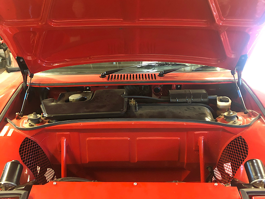
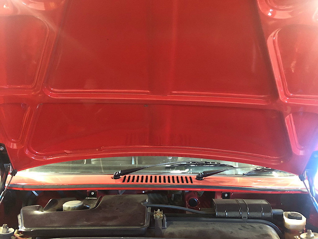
My plan is to seal off this top planform area best I can, and use a thermal blanket on the front of the bulkhead and underside of cover.
Posted by: Matty900 Sep 1 2020, 12:01 PM
We got the 1st set of Carbon fiber parts done but realized that I need to get the GT hood pins. We are working on the balsa wood reinforcement that will go on these. The weight savings is drastic but don't think that I really need that with 400+ hp.
Attached thumbnail(s)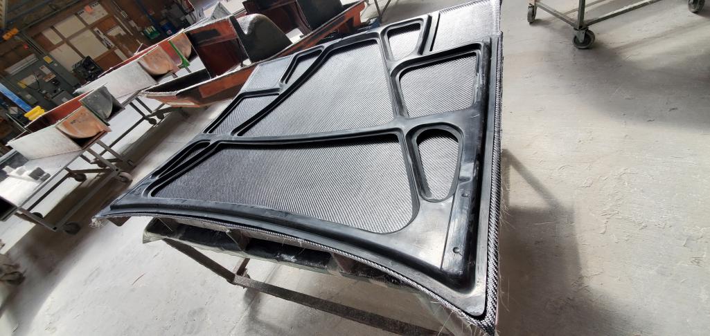
Posted by: FL 000 Sep 6 2020, 01:21 PM
We got the 1st set of Carbon fiber parts done but realized that I need to get the GT hood pins. We are working on the balsa wood reinforcement that will go on these. The weight savings is drastic but don't think that I really need that with 400+ hp.
Wow that sure looks nice. Would have to seriously consider leaving the underside as is it I had one of those.
Posted by: FL 000 Sep 6 2020, 01:39 PM
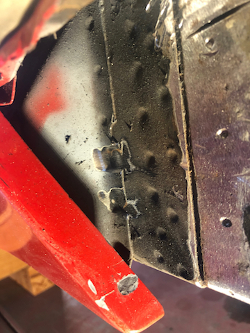
I signed up for the WCR in Nov so time to get some work done. I used my stud welder to try and pull the rear jack support piece back straight. Got it closer but ended up over pulling in a few areas that created raised dimples. 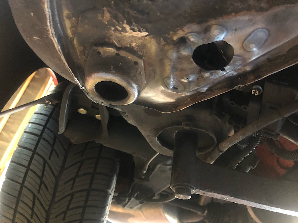
Ended up removing it to hammer and dolly it. Didn’t take as long as I thought it would to remove. On a side note I was surprised how easy it was to straighten a number of areas on the floor pan using a hammer inside the car. I didn’t pay much attention to the underside when I went through the car the first time, but when I am done with this I think it will look pretty straight. A little surface rust underneath but nothing too bad. 
I know many of you can walk circles around me with metal work, but I think these turned out well given my skill level for a couple hours work. Here are some before and afters. 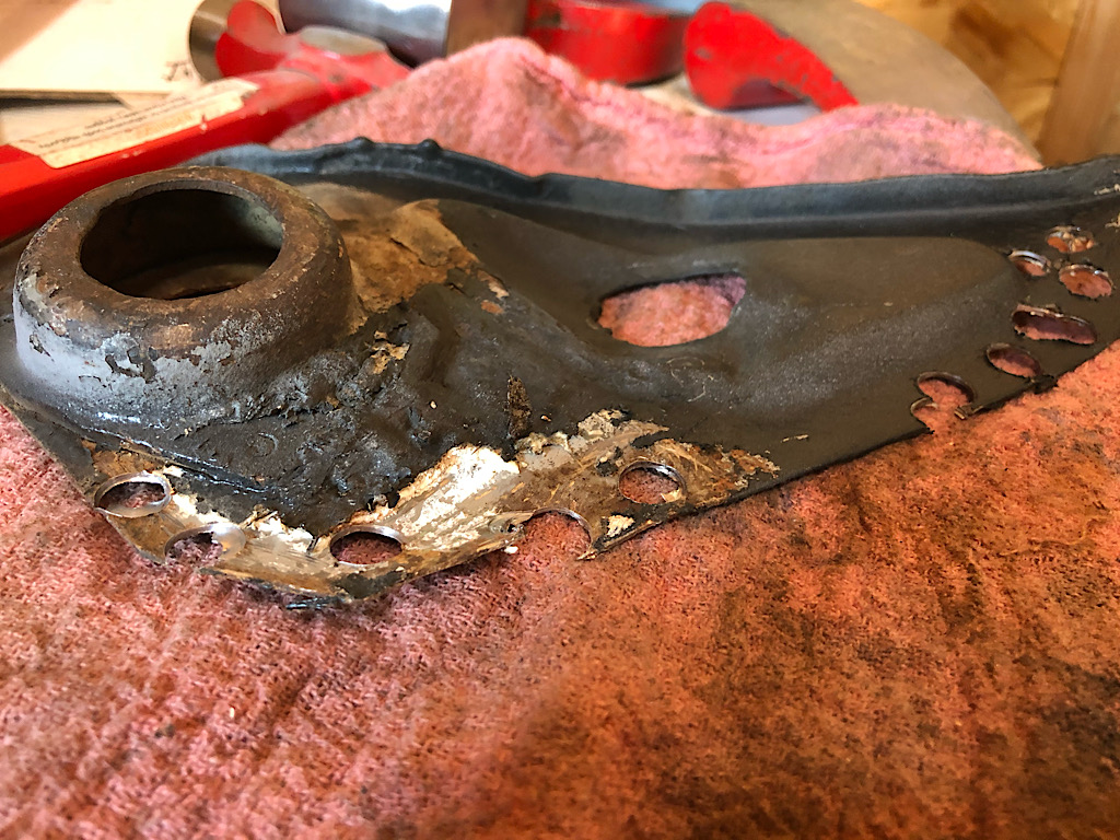
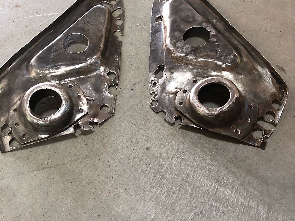
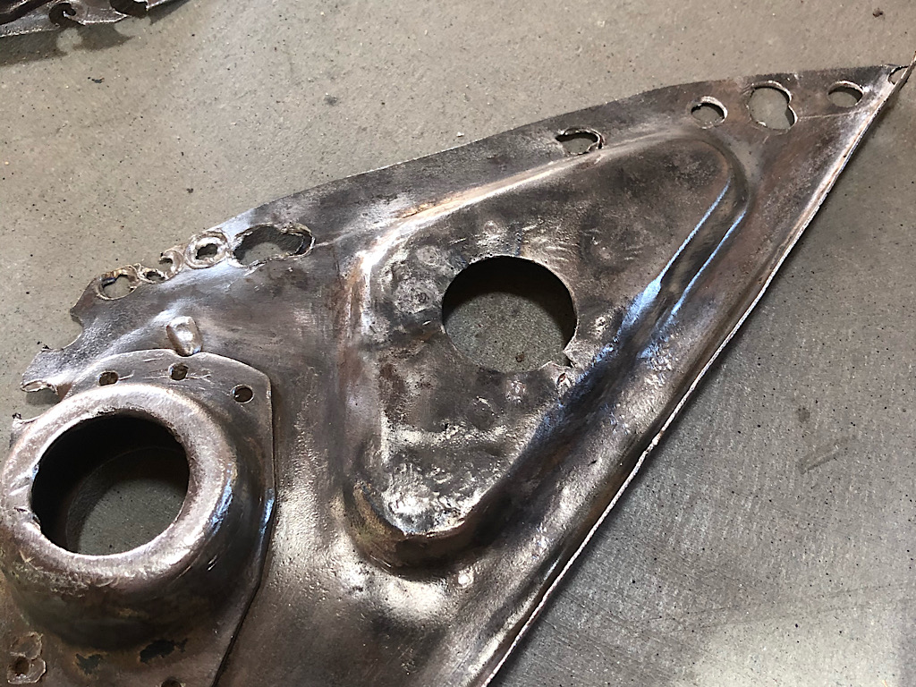
Should I fill in with any other of those holes I drilled or just reuse them all for plug welds when reattaching?
Posted by: FL 000 Sep 6 2020, 01:55 PM
Next up got the car on supports to adjust the door gaps for the long kit. A bit scary having it resting in a couple pieces of lumber and jack stands, but I have other platforms under each wheel in case she decides to fall. I think I’ll limit the time my skull is under the car too. 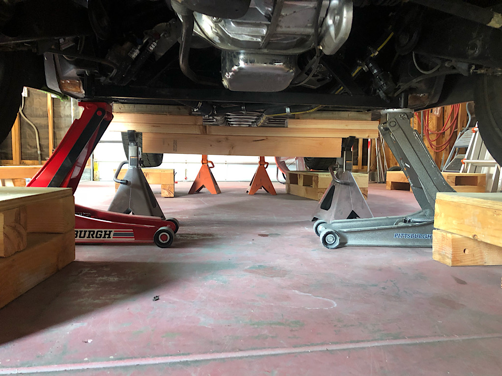
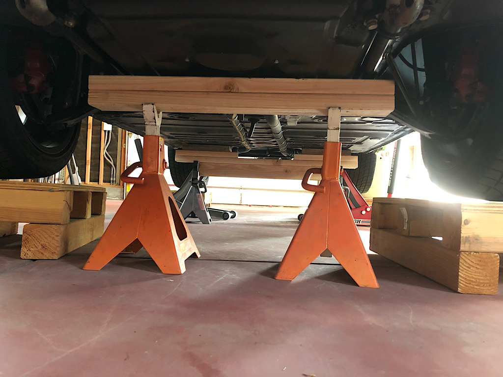
Here are my driver and passenger side door gaps as resting on the supports without anything else supporting the rear: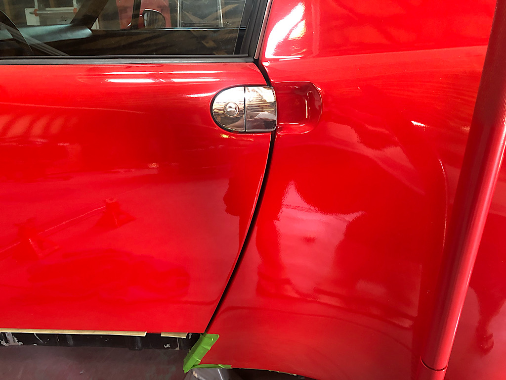
I’m pretty happy with the passenger door gap as shown here. Driver side will need to be closed up a bit. Calling on @http://www.914world.com/bbs2/index.php?showuser=2388 and others - my plan is to weld the passenger side long kit in first since the gap is good, then use a jack under the trans to lift and close the driver side door gap to the right amount before welding in the driver side. My assumption is the passenger side won’t move while doing this. Good assumption or no? I would like to do this with the doors attached so no easy way I am aware of to set both driver/passenger gaps before welding.
Posted by: 76-914 Sep 6 2020, 02:21 PM
Insert some wood shims from inside between the door jamb and door?
Posted by: 914forme Sep 6 2020, 05:57 PM
You will always get a bit of shrinkage when you weld, the key is controlling it.
Once you get the passenger side set, then it would be fine to jack up the back and put it close to where you want it.
I would also investigate and look at your door opening and door lengths. And check the pins for wear would also be a good idea.
You can use a rod end at the upper seatbelt, to the lower front. Please please please if you goto the store and pickup a turn buckle make sure it is big, the bigger the better, and it is forged. Cheap ones will blow up, and if it doesn't your very lucky. If it Dows, metal bits go flying about your garage, getting stuck in various items hopefully not you.
But if you want to try closing up the gap, just lower it down on its rear wheels, you gap will close right up, then pick it up in the middle right at the jamb. and fine tune your gap.
Hopefully it is you pins are worn, easy enough fix, and you can get on with it.
Have fun playing with molten metal, I know I always do.
Posted by: FL 000 Sep 16 2020, 07:37 PM
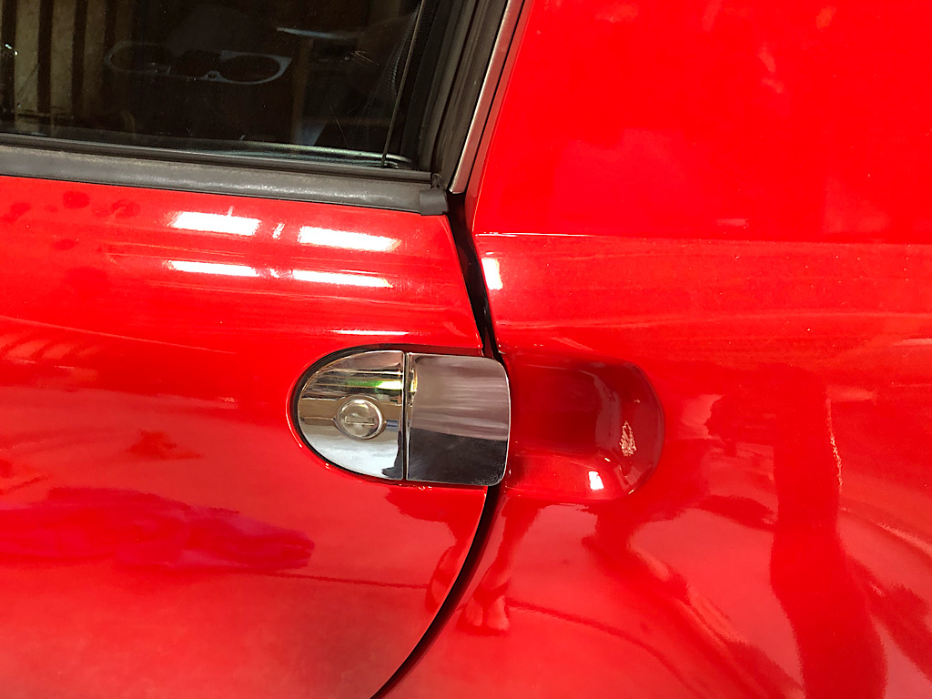
Well that sucks. Got passenger long reinforcement welded in with gap set as desired and this was the result with weight on wheels. Not sure how evident it is from picture, but gap closed up quite a bit. No more rubbing so I guess that is good.
Door is functional so going to put problem to back burner again. Short of a frame bench I think a roll cage may be my only at home solution at this point. Don’t really want a roll cage so need to ponder on it for awhile.
The longs do the majority of the work keeping the door gap set, so I wonder if my flex is happening in the metal above it, with the shock being the lever to bend it all forward.
Attached image(s)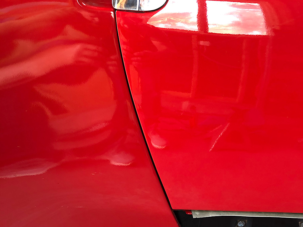

Posted by: 914forme Sep 17 2020, 08:39 PM
One other way is open it up, and add a metal roof and make it a coupe.
Theater solution is the 914LTD kit.
But I am thinking you might want to take a closer look at your logs.
Posted by: FL 000 Oct 11 2020, 09:05 AM
I see a couple threads on brake related items so this is fitting. I have been busy the last few weeks (more to come on progress) but need to fast forward to last night.
Bleeding my brakes with my Motive pressure bleeder as I have done numerous times before. I am at the right rear wheel and hear what sounds like a sprinkler...in my garage.
Stand up and go to front of car and there is a heavy stream of brake fluid, more like a gusher, shooting up at underside of the hood and coming down all over the front of the car
We all know brake fluid and paint don’t match right? Long story short I cleaned up what I could, rinsed with a bunch of water, followed by dish soap and then another rinse. I didn’t see any paint residue while cleaning so may have gotten lucky.
Oh yeah the culprit was the hose that connects to the bleeder tank ruptured. I know things can fail but not sure if I will be using it again any time soon. 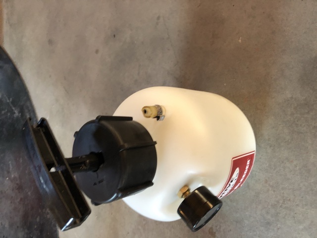
Posted by: 76-914 Oct 11 2020, 09:20 AM

Posted by: FL 000 Oct 11 2020, 11:42 AM
So going back a few weeks I finished up my 914LTD install. The driver side went on pretty smooth with my lessons learned from the passenger side. Also I wasn't fighting a bent long and a bunch of preload (best I can assume) so it was really just getting it set in place.
Here are some pics fro the passenger side and notes about the install.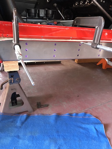
I added a few extra holes for each rib, and in hindsight, the lower ones shown were too low and didn't make good contact with the long. After tacking the two pieces together I removed it through the rear wheel well to finish welding them together on the ground; with the Sheridan kit I couldn't do it on the car.
Posted by: FL 000 Oct 11 2020, 11:51 AM
Some finish work on the welds, liberal use of seam sealer, and paint to call it good.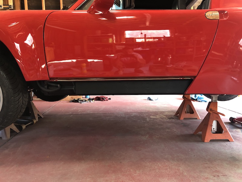
Posted by: FL 000 Oct 11 2020, 12:01 PM
I noticed my rear trailing arm bushings were not in good shape and preventing the arm from moving freely. Figured it was a good time to install an Elephant Racing polybronze set. Fairly straight forward install and amazing how easy yet precise the arm moves now. Forgot to take pics of this one.
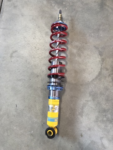
Years ago when I installed my coil overs I cheaped out on the helper springs and used some wire to keep the spring attached to the top hat. Every time you lift the car the lower part of the springs rise out of their seat and need to find their way back in when lowered. As you can see from the picture it can give your threaded sleeve a beating. I know others have done this successfully so to each their own. I added the helpers since I was already in there.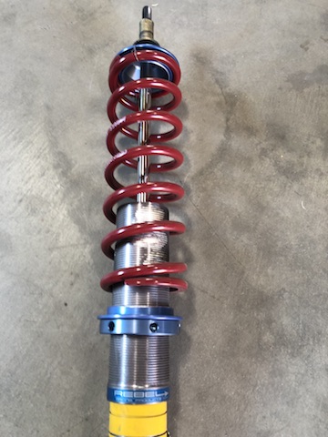
Posted by: FL 000 Oct 11 2020, 12:13 PM
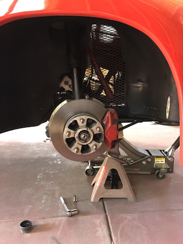
Next I moved onto the fun stuff I have been looking forward to for a while. I acquired a set of Boxster S calipers, rotors, and adapters recently (hat tip to Stephen @http://www.914world.com/bbs2/index.php?showuser=2388 ) and figured with the trailing arms off I was already halfway there.
If you are this far into my thread you clearly know I don't mind deviating from the beaten path and open to trying a different approach. I really want to have a parking brake when this is done, but wasn't having great luck finding the 911 parts. I decided to go with the Wilwood MC-4 style parking brake. I knew it would require some fabrication and a different cable to make it work.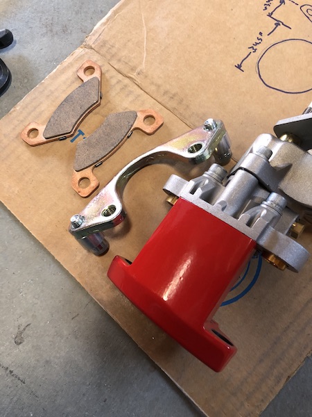
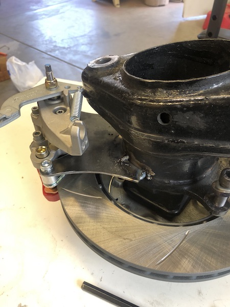
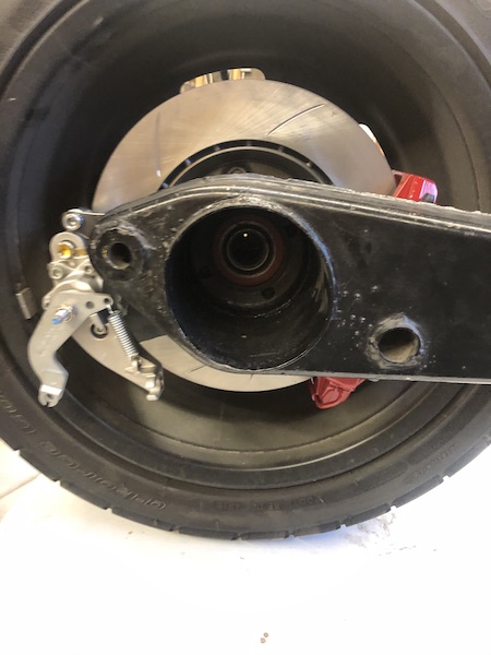
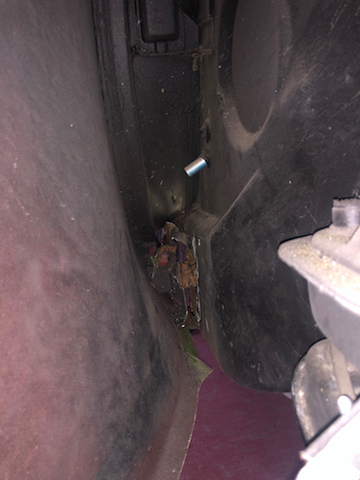
These pics were during the mockup but you can see where I am trying to go with it.
Posted by: FL 000 Oct 11 2020, 12:28 PM
Got to love these comparison pics. I know there are more variables than just the physical size of the calipers/rotors, but looks cool.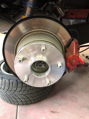
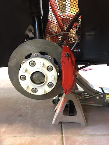
My wife helped me bleed them the old school way and after 2 trips around the car I think I have good enough pedal feel for a road test. Need to do a couple other minor things first so maybe tomorrow or later in the week.
I'll consider realigning the rear trailing arms after that. I also need to figure out the parking brake actuation piece. I thought I could have some custom cables made but running into some challenges there. Maybe a good opportunity to install some linear actuators but that may take more time than I have right now (WCR right around the corner).
Posted by: FL 000 Oct 18 2020, 07:17 PM
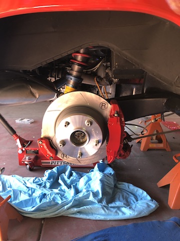
Wow, loving the big brakes. Haven’t done a full on panic stop yet but all indications say way more braking capacity available than my previous setup. I did the PMB recommended bedding-in procedure and putting some miles on it to build confidence.
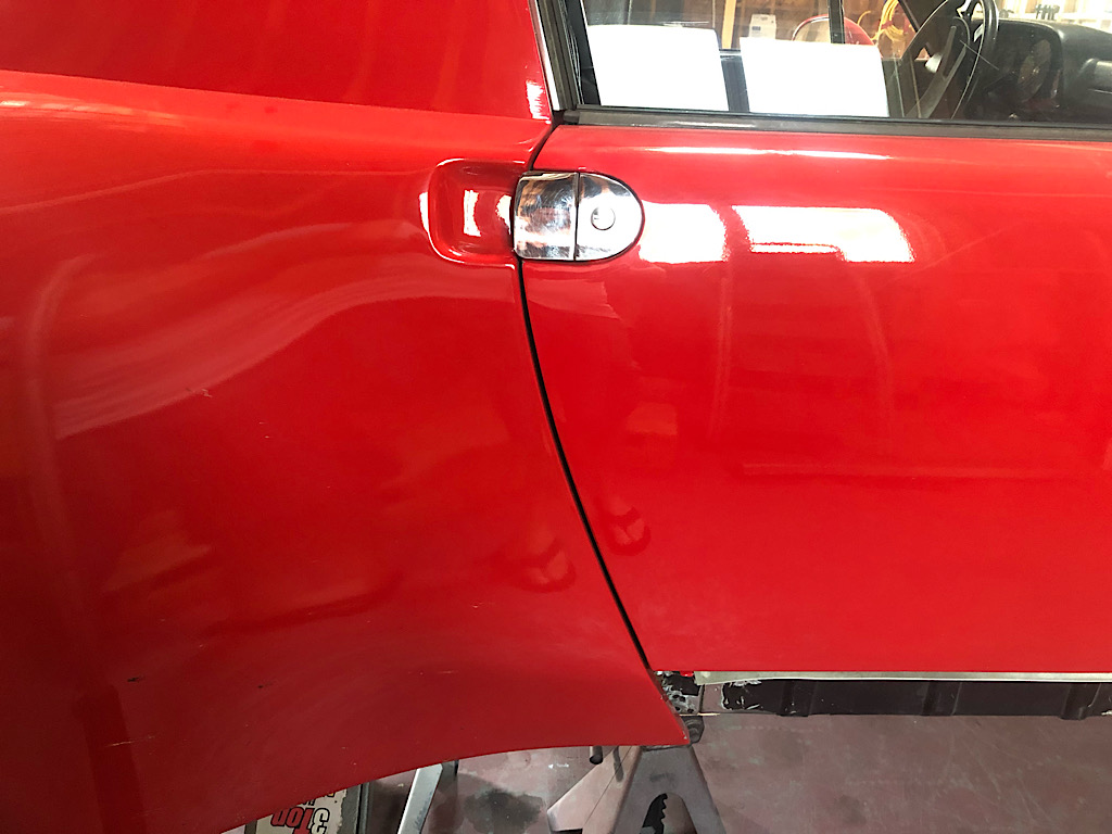
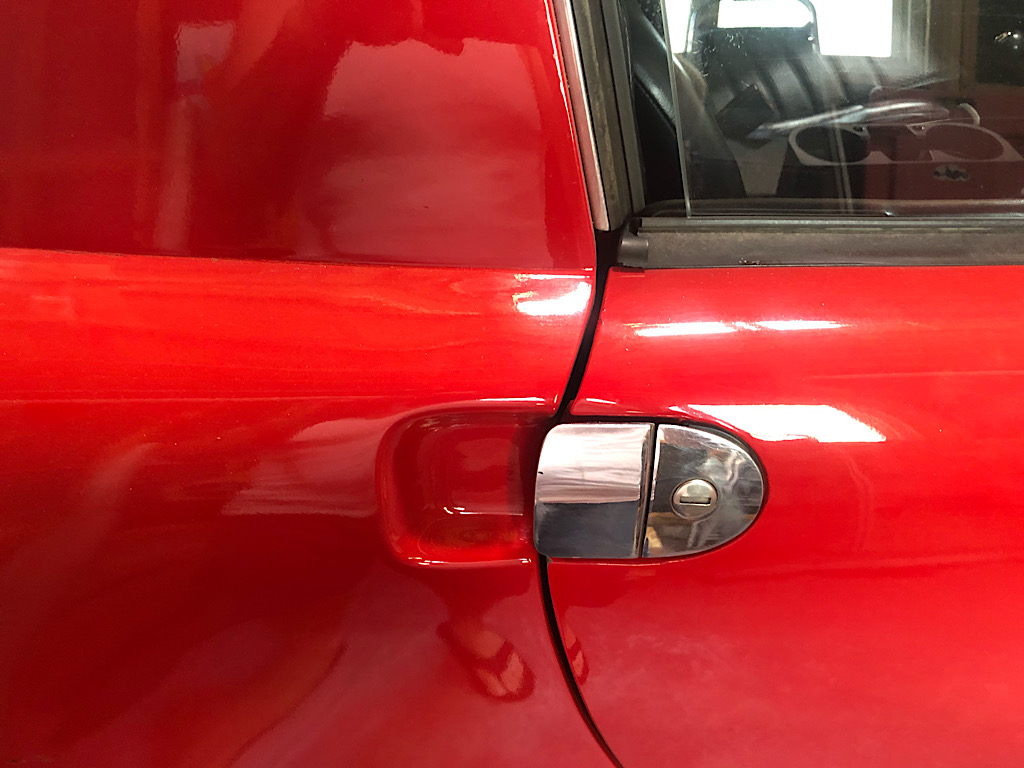
Also changed my little plastic do-dad in the passenger door exterior handle and that door opens fairly easily now. May still address the door gap down the road but satisfied with functionality for now.
Went full circle on the parking brake cables and turns out Wilwood makes a universal kit for their caliper - go figure 
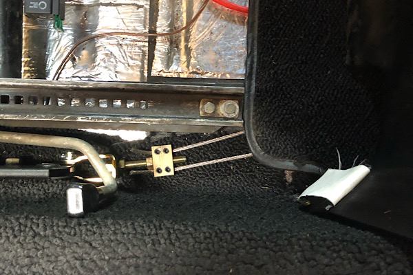
I now have functional parking brakes again and here is the setup under the car: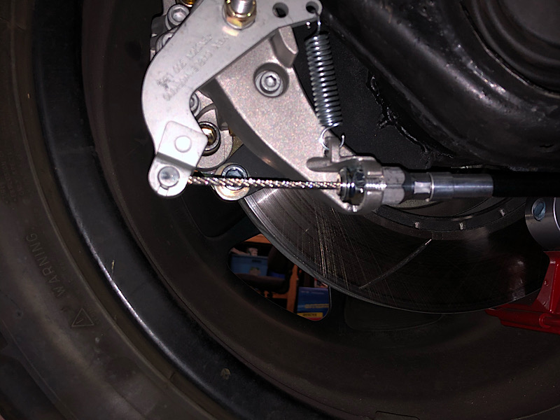
Posted by: FL 000 Oct 18 2020, 07:29 PM
Inside the cabin I started by removing the metal guide plate. Still a mystery to me in identifying where all the spot welds are 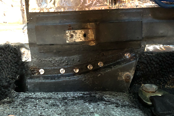
I didn’t want to prep and spray paint in this area, so I put down some Ospho to at least coat it and hopefully ward off any future rust. 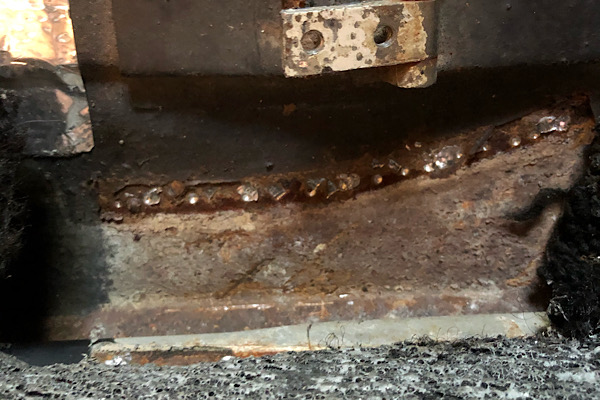
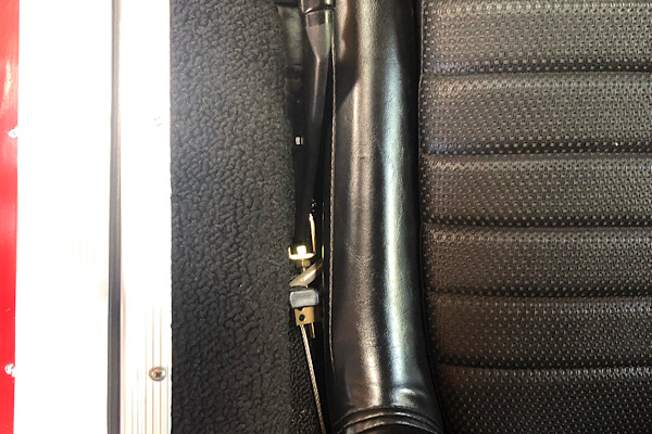
Ran the steel cables through the factory pipes and this is the (almost) final setup. You’ll note the angle of the wires to the handle is a bit extreme. I think I will go back in and use part of the guide plate I removed to help correct the angle and put less stress on the handle. Another day 
Posted by: 76-914 Oct 19 2020, 10:01 AM
Looks good. With the weight of the V8 you needed some larger brakes.
Posted by: FL 000 Nov 8 2020, 03:24 PM
I felt like my car was dialed in before heading out for WCR on Thursday morning. Even went so far as to jinx myself on that thread
Met the So Cal crew in Gorman and headed out. On the way to our first stop at Harris Ranch I started to notice valve chatter. Checked my oil while there and was barely registering on the dipstick. Threw a quart in (thanks @http://www.914world.com/bbs2/index.php?showuser=19195 , I still owe you so pm me a shipping address or let me know next time you are in my area) and hit the road. 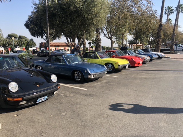
Next stop 120 miles or so up the road and a couple quarts lower, smell of oil while driving, and visible oil coming from right front top side of engine. Still running ok so decided to press ahead. Rolled into Petaluma with engine running poorly and minor backfires.
Enjoyed the evening with the group and made the decision right before the 0900 meetup on Friday that we could probably nurse it home if we left then. Took it easy and made the 400 miles back somehow. 800 miles round trip in 2 days and added about 8 quarts of oil along the way to make it happen.
Posted by: FL 000 Nov 8 2020, 03:40 PM
Decided I was going to do the Audi 01E install after WCR so now I need to throw some engine work in too. Probably won’t completely change gears at this point (so to speak) but it is a good opportunity to do some more with the motor at the same time.
Guesses on what happened before I tear into her? Symptoms that I know of:
-Oil leaking about a quart per 100 miles as described in previous post
-Engine running rough, underpowered, and backfire on right exhaust side
-when hard on or off accelerator oil spraying out and making it out engine lid and then to rear trunk
-does not appear to be coming out of passenger side breather although in the same vicinity.
-Radiator fluid no longer pure antifreeze color, looks dirty, but not leaking and not overheating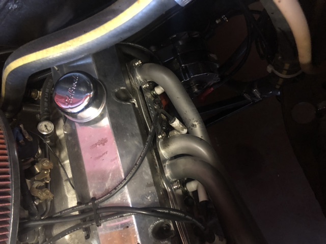
Posted by: Mueller Nov 8 2020, 03:44 PM
I parked next to you at the hotel (beat up light ivory 914) and was looking forward to checking out your car. Glad you made it back home.
I have the same parking brakes, however they are still in the box so I am without functioning parking brakes right now....hopefully for not too long.
Nice 914 build for sure.
Posted by: FL 000 Nov 8 2020, 03:56 PM
I parked next to you at the hotel (beat up light ivory 914) and was looking forward to checking out your car. Glad you made it back home.
I have the same parking brakes, however they are still in the box so I am without functioning parking brakes right now....hopefully for not too long.
Nice 914 build for sure.
Too bad we didn’t get a chance to meet up. If you want more info on what I did for my parking brake setup just let me know.
Posted by: 76-914 Nov 8 2020, 06:26 PM
I felt like my car was dialed in before heading out for WCR on Thursday morning. Even went so far as to jinx myself on that thread
Met the So Cal crew in Gorman and headed out. On the way to our first stop at Harris Ranch I started to notice valve chatter. Checked my oil while there and was barely registering on the dipstick. Threw a quart in (thanks @http://www.914world.com/bbs2/index.php?showuser=19195 , I still owe you so pm me a shipping address or let me know next time you are in my area) and hit the road.
Next stop 120 miles or so up the road and a couple quarts lower, smell of oil while driving, and visible oil coming from right front top side of engine. Still running ok so decided to press ahead. Rolled into Petaluma with engine running poorly and minor backfires.
Enjoyed the evening with the group and made the decision right before the 0900 meetup on Friday that we could probably nurse it home if we left then. Took it easy and made the 400 miles back somehow. 800 miles round trip in 2 days and added about 8 quarts of oil along the way to make it happen.
Never fails.

Posted by: FL 000 Nov 14 2020, 02:37 PM
Alright here’s the next clue from the first peak inside the engine. These are “new” and have about 1000 miles on them. 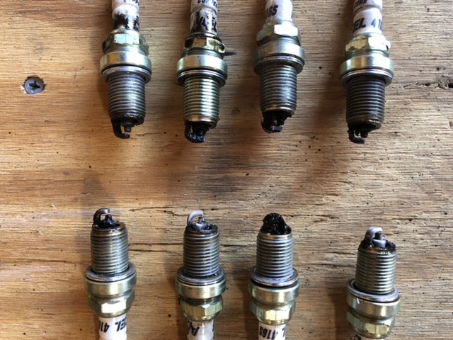
Bottom left on pic is front driver side for reference. The rest are in order.
Posted by: bkrantz Nov 14 2020, 08:32 PM
Well that sucks. Got passenger long reinforcement welded in with gap set as desired and this was the result with weight on wheels. Not sure how evident it is from picture, but gap closed up quite a bit. No more rubbing so I guess that is good.
Door is functional so going to put problem to back burner again. Short of a frame bench I think a roll cage may be my only at home solution at this point. Don’t really want a roll cage so need to ponder on it for awhile.
The longs do the majority of the work keeping the door gap set, so I wonder if my flex is happening in the metal above it, with the shock being the lever to bend it all forward.
How is the front gap? It is possible to shift the door forward slightly, with a bit of persuasion of the B-pillar hinge mount spots (with a block and hammer and feeling brave).
Posted by: 76-914 Nov 15 2020, 10:06 AM
Damn. So many possibilities. Where is the origin of the oil leak? So many fouled plugs, too! Have you done a leak down test yet? Sounds like a head gasket leak between the water & oil passages but not between the cylinders. The odd thing is fouled plugs on both sides. 0 chance of blowing head gasket on both sides or cracked heads on both sides unless it overheated but you'd have noticed that. Looking forward to seeing what you find when you tear it down.
Posted by: FL 000 Nov 15 2020, 05:32 PM
How is the front gap? It is possible to shift the door forward slightly, with a bit of persuasion of the B-pillar hinge mount spots (with a block and hammer and feeling brave).
I have always been one of those guys that over tightens, over bends, etc so to be honest I am afraid to try to push too much on the hinge side
With that said I have done some of that with a hydraulic ram and some lifting on the door but the front gap is pretty good so figured I would leave it alone...at least for now!
Posted by: FL 000 Nov 15 2020, 05:38 PM
Damn. So many possibilities. Where is the origin of the oil leak? So many fouled plugs, too! Have you done a leak down test yet? Sounds like a head gasket leak between the water & oil passages but not between the cylinders. The odd thing is fouled plugs on both sides. 0 chance of blowing head gasket on both sides or cracked heads on both sides unless it overheated but you'd have noticed that. Looking forward to seeing what you find when you tear it down.
No leak down test yet but may once I get the engine and trans removed. I did a compression test before WCR and all were in the 150 psi area. Guessing that isn’t the case now
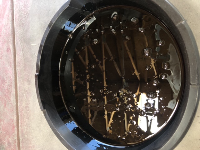
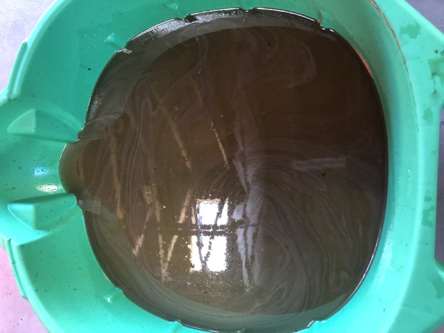
Here is the oil and coolant; kind of hard to tell which is which right?! The coolant was a nice green last I checked.
Posted by: Chris914n6 Nov 16 2020, 01:38 PM
Your bulkhead seal is missing the flap that the factory seal has that actually contacts the trunk lid. It should help greatly with the blow by issue.
Posted by: 76-914 Nov 16 2020, 10:39 PM
Damn. So many possibilities. Where is the origin of the oil leak? So many fouled plugs, too! Have you done a leak down test yet? Sounds like a head gasket leak between the water & oil passages but not between the cylinders. The odd thing is fouled plugs on both sides. 0 chance of blowing head gasket on both sides or cracked heads on both sides unless it overheated but you'd have noticed that. Looking forward to seeing what you find when you tear it down.
No leak down test yet but may once I get the engine and trans removed. I did a compression test before WCR and all were in the 150 psi area. Guessing that isn’t the case now
Here is the oil and coolant; kind of hard to tell which is which right?! The coolant was a nice green last I checked.
The top pic is from the radiator and the lower from the oil pan?
Posted by: Rider914 Nov 17 2020, 02:52 PM
Wow - Did you cross your oil cooler and water coolant return lines? Sorry, wish it was that simple... Good luck
Posted by: djway Nov 17 2020, 03:17 PM
Head gasket?
Posted by: FL 000 Jan 8 2021, 08:03 PM
Your bulkhead seal is missing the flap that the factory seal has that actually contacts the trunk lid. It should help greatly with the blow by issue.
Yeah another lesson learned for me. When I did all the bodywork for the fiberglass hood and fenders I did many fit checks, but none with the seal on. After paint when reassembling the hood with the seal on, it pushed the hood up enough to make the lines unacceptable. Trimming it down solved the problem. May go back and do a better job making sure the seal fully contacts the hood.
Posted by: FL 000 Jan 8 2021, 08:05 PM
Damn. So many possibilities. Where is the origin of the oil leak? So many fouled plugs, too! Have you done a leak down test yet? Sounds like a head gasket leak between the water & oil passages but not between the cylinders. The odd thing is fouled plugs on both sides. 0 chance of blowing head gasket on both sides or cracked heads on both sides unless it overheated but you'd have noticed that. Looking forward to seeing what you find when you tear it down.
No leak down test yet but may once I get the engine and trans removed. I did a compression test before WCR and all were in the 150 psi area. Guessing that isn’t the case now
Here is the oil and coolant; kind of hard to tell which is which right?! The coolant was a nice green last I checked.
The top pic is from the radiator and the lower from the oil pan?
That’s funny, actually the top pic is from oil pan and bottom is the coolant. It was a mess.
Posted by: FL 000 Jan 8 2021, 08:11 PM
Alright it turns out the heads were jacked up. Took it to my local machine shop and they went through them both. The said tons of carbon deposits on the intake valves. All the valves and guides checked good, so they basically just gave it a valve job and replaced the seals. I wouldn’t have thought valve seals alone could cause the oil consumption I was seeing, but I have a lot of confidence in the shop so assuming they are good now. 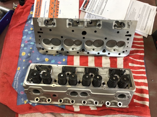
Sure look nice all cleaned up.
Posted by: FL 000 Jan 8 2021, 08:18 PM
So put my heads on tonight and adjusting the valves and this happens 
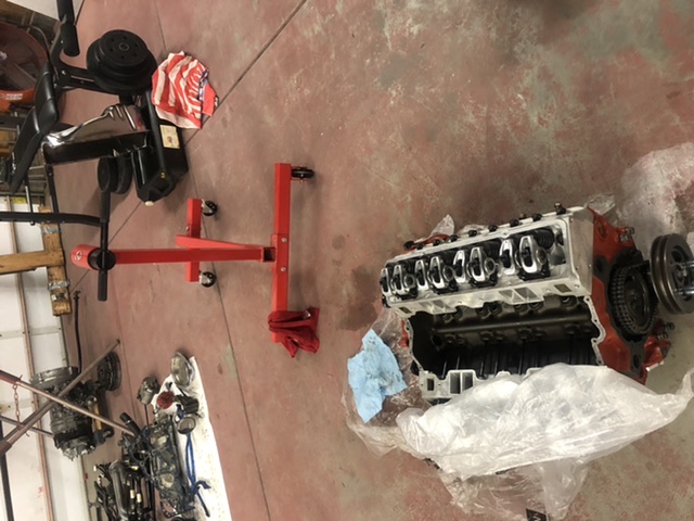
Yeah, rotating crank and engine literally falls off the stand without warning. Luckily didn’t land on me or my feet. Base of stand took initial impact and then it fell final few inches to the ground. Scary. 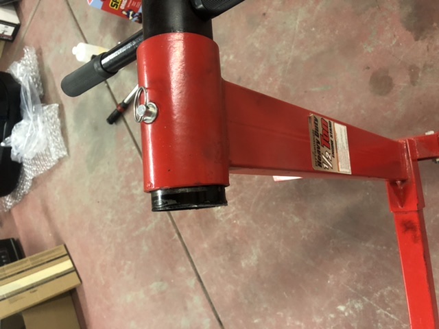
Too upset to assess damage tonight so will get it in the air tomorrow. Just curious if this has happened to anyone else before?
Posted by: rhodyguy Jan 8 2021, 09:13 PM
WOW! That could have been a life changing event. Sorry for the hassle. It'll work out.
Posted by: djway Jan 8 2021, 09:28 PM
Holy Crap.
What brand is that stand?
Glad you still have both legs.
Posted by: FL 000 Jan 9 2021, 10:14 AM
Holy Crap.
What brand is that stand?
Glad you still have both legs.
Harbor freight 1/2 Ton. Lightly used and never abused. Might be overkill but I think I will always use my crane as a backup from now on.
Posted by: 808 WRX Jan 9 2021, 10:48 AM
Glad your feet are ok! Hope the motor is ok too.
Was it pressed on? Or is that a little ring of broken weld?
Either way, I'm gunna have to check out my engine stand and make sure its welded all around, both sides! 
Posted by: 76-914 Jan 9 2021, 10:24 PM
Aww Man. Sorry dude. I've got one of those but never put anything more than an aluminum 6 on it. It seemed it was at it's limits with the 6 on it, though. Hang tough.
Posted by: cali914 Jan 10 2021, 01:29 AM
You are lucky from the head situation and the accident. Get a edelbrock programmable fuel injection kit and you will be so happy.
Posted by: Andyrew Jan 10 2021, 01:33 AM
Wow that is nuts with the engine stand! I have the same one. Looks like a failed weld or no welding at all... Makes we want to check mine...
Hopefully the damages are just the oil pan??
I had my first v8 engine fall over on me. But I still had a tire attached to it from when we grabbed it from a pick n pull....
Posted by: djway Jan 10 2021, 01:39 AM
Holy Crap.
What brand is that stand?
Glad you still have both legs.
Harbor freight 1/2 Ton. Lightly used and never abused. Might be overkill but I think I will always use my crane as a backup from now on.
I can’t even see a weld...
Posted by: FL 000 Jan 10 2021, 10:53 AM
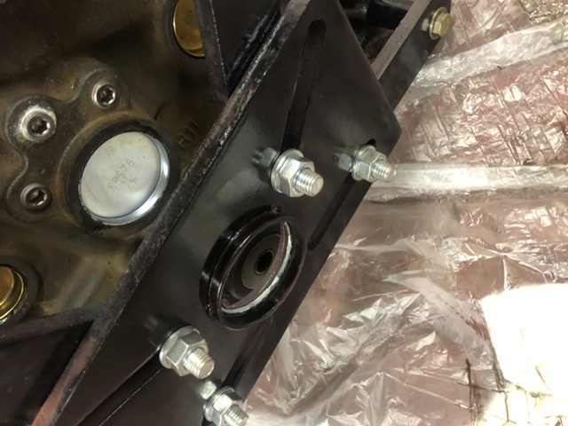
A couple more pics that may help some of you with a better eye than me. With the material still showing in the top one it does look like it was welded and broke there. 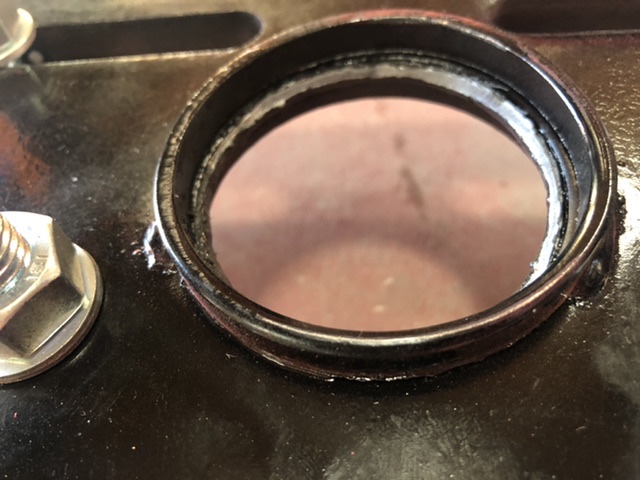
And now here is my current setup. A little more difficult to work on it and flip over but not that big of a deal. 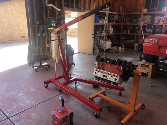
Posted by: FL 000 Jan 10 2021, 11:01 AM
You are lucky from the head situation and the accident. Get a edelbrock programmable fuel injection kit and you will be so happy.
I am seriously considering the Edlebrock Pro Flo 4. I am fairly sure having an untuned carb and timing off messed my heads up. I need something with an ECU to help make that stuff easy for me.
Went back and forth on LS, Audi twin turbo, and others but staying the course on SBC for now. Money is part of it (debatable on how much more/less to go these routes) but mainly it boiled down to getting it back on the road as soon as possible. Not sure I can handle a 1-2 year project and just want to drive

Posted by: FL 000 Jan 10 2021, 11:18 AM
Hopefully the damages are just the oil pan??
Wish I had the oil pan on it
The crank pulley and one of the crankshaft counter weights took the brunt of the impact. Engine landed on the stand first which was more forgiving than straight concrete. Other than the tiniest marks on those areas, nothing visibly broken. With a cast crank who knows if it was damaged seriously and what will happen when I fire it up.
Rotating assembly still turns smooth, and going to press on ahead since I don’t want to drop more money into this block. It will still be fine for getting my trans mounted and all the tidbits that go along with that. Then I can figure out the longer term replacement for this engine.
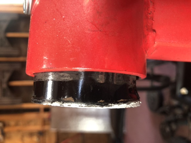
Posted by: djway Jan 10 2021, 12:36 PM
If it was welded it doesn’t look like the weld penetrated so essentially it wasn’t welded.
That should be brought to their attention.
Posted by: FL 000 Jan 10 2021, 01:36 PM
If it was welded it doesn’t look like the weld penetrated so essentially it wasn’t welded.
That should be brought to their attention.
Good call, reported it at saferproducts.gov
A quick google search turned up empty so maybe this was a one off occurrence, but who knows.
Posted by: FL 000 Jan 11 2021, 09:27 PM
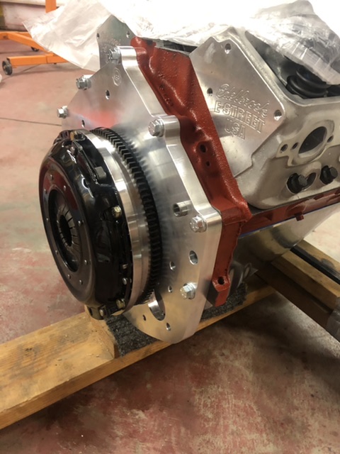
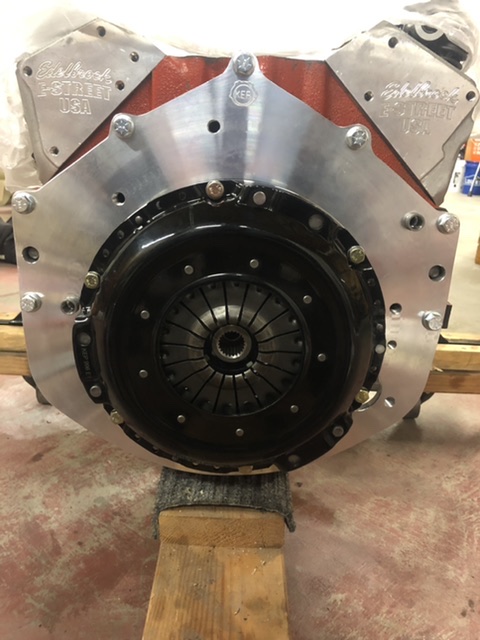
Alright back to happier times. Got the 01E mounted to the engine. Will probably come half a dozen more times but feels good seeing them together. 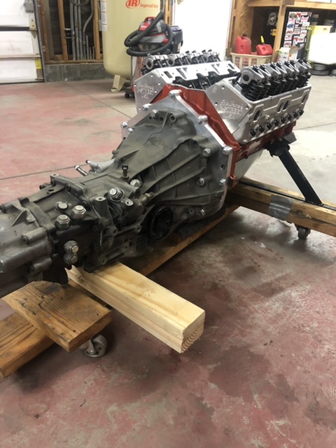
Posted by: djway Jan 12 2021, 01:26 AM
Alright back to happier times. Got the 01E mounted to the engine. Will probably come half a dozen more times but feels good seeing them together.
PURDY
Posted by: cali914 Jan 12 2021, 11:19 AM
nice
Posted by: tygaboy Jan 12 2021, 12:40 PM
Great to see things going back together! 
Posted by: FL 000 Jan 24 2021, 07:26 PM
Calling all out there. Modifying my gas tank for an internal fuel pump and got it this far. Looks fairly good to the eye. 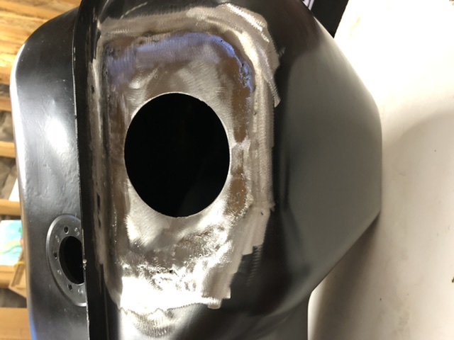
Then shine a light behind it and see this all around the patch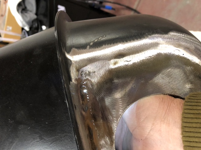
What’s the next step? Keep chasing each hole down with MIG? Switch to TIG? Is there something I can just coat it with and call it a day (only partially joking). The metal is pretty thin and worried about getting into a cycle of tacking, sanding, and continuing to burn through the ever thinning metal.
Thanks
Posted by: 76-914 Jan 25 2021, 08:38 AM
Calling all
out there. Modifying my gas tank for an internal fuel pump and got it this far. Looks fairly good to the eye. Then shine a light behind it and see this all around the patch
What’s the next step? Keep chasing each hole down with MIG? Switch to TIG? Is there something I can just coat it with and call it a day (only partially joking). The metal is pretty thin and worried about getting into a cycle of tacking, sanding, and continuing to burn through the ever thinning metal.
Thanks
You can buy a repro from Pelican for ~ $200.
Posted by: tygaboy Jan 25 2021, 09:15 AM
When I welded on my tank:
Go with TIG, very sharp, longer than normal taper length on the tungsten, very thin filler rod, perhaps even MIG wire. You're after the smallest HAZ possible.
I didn't use the following technique on the tank in my pic but:
Tape over all the openings leaving room to insert a shop vac hose in one of them. Put a sock or something over the end of the hose and leave enough room around the hose so that when the vac is on, you're creating a SLIGHT vacuum inside the tank. Yes, this is very unscientific, but...
The vacuum causes the weld puddle to pull inward and leaves less weld material sitting higher than the parent layer that requires grinding. YMMV.
Hope this helps.
Attached thumbnail(s)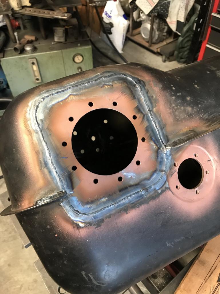
Posted by: FL 000 Jan 25 2021, 05:50 PM
You can buy a repro from Pelican for ~ $200.
Hey Kent, forgot to mention this is a reproduction tank I got from parts geek for ~$200. I decided to cut a large section out of the top to remove the internal baffle and make room for my new pump/baffle.
I’ll show a few pics of what I did in a bit.
Posted by: FL 000 Jan 25 2021, 05:59 PM
When I welded on my tank:
Go with TIG, very sharp, longer than normal taper length on the tungsten, very thin filler rod, perhaps even MIG wire. You're after the smallest HAZ possible.
I didn't use the following technique on the tank in my pic but:
Tape over all the openings leaving room to insert a shop vac hose in one of them. Put a sock or something over the end of the hose and leave enough room around the hose so that when the vac is on, you're creating a SLIGHT vacuum inside the tank. Yes, this is very unscientific, but...
The vacuum causes the weld puddle to pull inward and leaves less weld material sitting higher than the parent layer that requires grinding. YMMV.
Hope this helps.
Thanks Chris, and I do plan to use the vacuum technique. I used it on my first patch attempt but I messed up the patch so bad (not due to vacuum) that I decided to cut it out and try again. This is my second attempt with a new welder, and although skill is probably more important than machine I am having much better luck


I got some silicon bronze tig rods too and may just try brazing the rest since I am just trying to cover pin holes at this point. New to TIG and will play around with the sharpening as you mentioned also
Posted by: Rider914 Jan 26 2021, 12:22 PM
WOW! That could have been a life changing event. Sorry for the hassle. It'll work out.
As bad as that went, it couldn't have gone any better...
Unfortunately, I have had to tell myself that many times over the years.
Posted by: FL 000 Mar 6 2021, 01:04 PM
WOW! That could have been a life changing event. Sorry for the hassle. It'll work out.
As bad as that went, it couldn't have gone any better...
Unfortunately, I have had to tell myself that many times over the years.
Definitely a good way to approach it! Feel exactly the same way.
Posted by: FL 000 Mar 6 2021, 01:17 PM
Haven’t posted in awhile but have been busy. Unfortunately working like 4 different things at same time so not much finished.
I did declare victory on the tank though. After multiple weld/grind/inspect cycles experimenting with MIG/TIG/brazing I got the top to only have a few remaining pinholes. Was mainly worried about slosh so put a finish coat of JB weld on it and sanded smooth to paint. 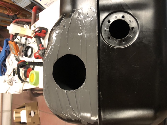
I wanted the bottom pinhole free with metal and muggy weld solder rods were what finally did the trick. Low enough temp that I was able to use heat gun and wicking allowed the solder to flow into the remaining holes. Didn’t attempt pushing my luck and sanding smooth so once I knew the leaks were gone I just painted it. 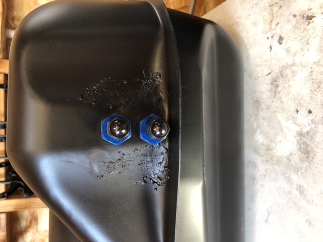
Relocated cap to driver side and basically have it setup like @http://www.914world.com/bbs2/index.php?showuser=19241 did on his; why reinvent the wheel when I can just capitalize on everyone’s trial and error and good ideas 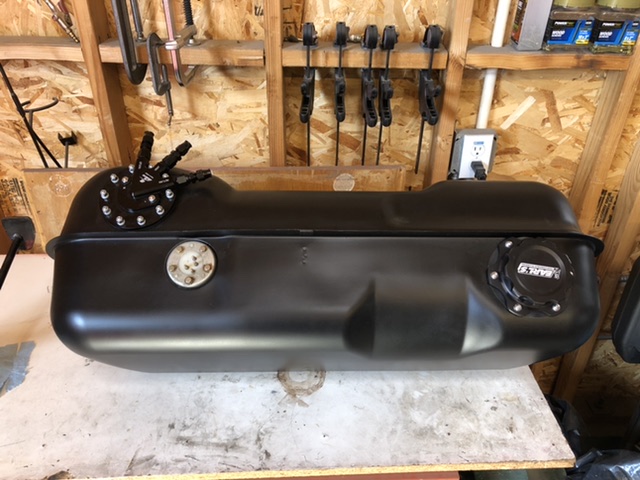
Posted by: FL 000 Mar 6 2021, 01:28 PM
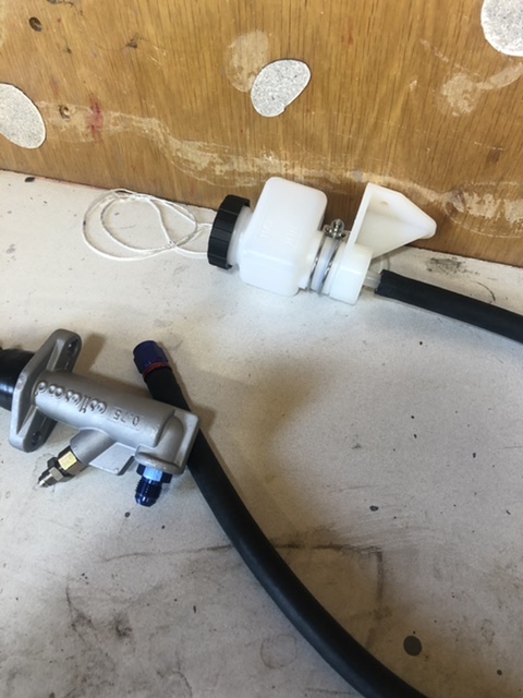
Also making progress on the clutch master cylinder. Wow it is tight adding a clutch master cylinder next to brake master but @http://www.914world.com/bbs2/index.php?showuser=29 took the guess work out with his bracket kit. 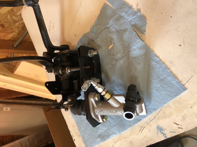
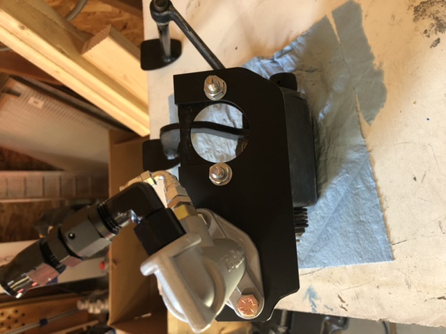
I rounded the corners to remove some excess material and to give the radiator hose something smooth to rest on.
I am going to use 3/8” aluminum tube from the M/C up behind tank and then transition to rubber hose for final connection to reservoir.
Apologies for rotated pics but doing this in car while daughter is getting horseback lessons and not in the mood to fight it!
Posted by: FL 000 Mar 6 2021, 01:36 PM
Here are some from under and above the pedal cluster. Following what @http://www.914world.com/bbs2/index.php?showuser=9964 and others have done with a few deviations here and there. 
The blue inlet fitting points right at the steering shaft so I swapped that out for a 90 degree fitting. 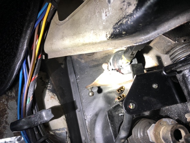
A little bit of glare from flashlight but you can see I grounded some of the accelerator linkage off to make sure it clears the clutch master bushing. Nothing scarier than letting off the gas and the car doesn’t respond been there done that.
Posted by: FL 000 Mar 6 2021, 01:51 PM
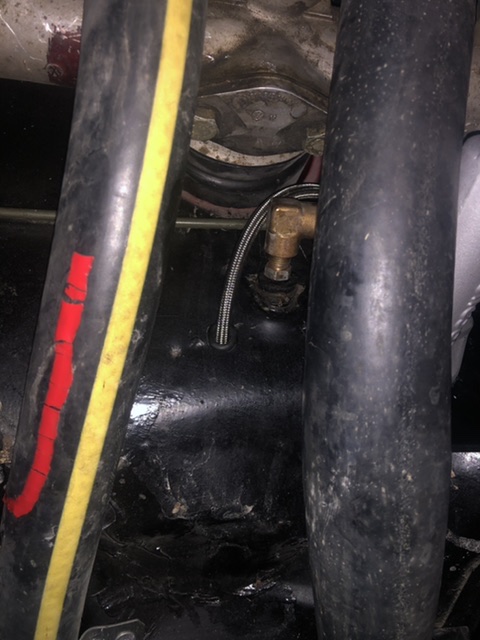
Nothing new that timing a SBC is a pain in the rear on a 914. Don’t have the best visibility to front of engine and stock timing tab doesn’t fit well either. Yes I know if I was smart and had an LS I wouldn’t have this problem, but maybe someday I will catch on
To give me the ability to check the timing I am using a factory hole in side of trans at about the 10 o’clock position , viewing from rear - or here (forward most of 2 side by side ones)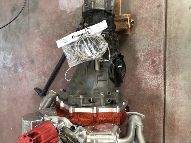
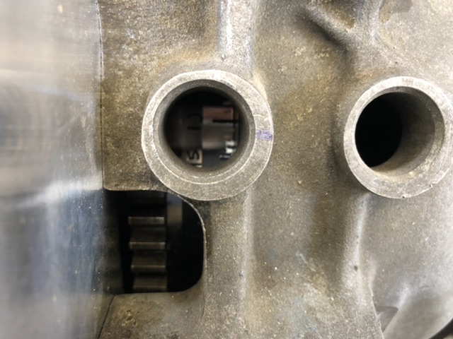
May not show well but I put a number of degree marks on the flywheel using a metal awl and a paint pen. Figured the paint will make it easy to see and the scratches will save the day of paint comes off!
Plan to use an old timing light I have, remove light and extend the wire length, and position snake cable style camera and timing light near hole to check when engine is running. Probably easier to see than explain, so will add pics later (if it works)
Posted by: FL 000 Apr 3 2021, 05:34 PM
Making slow but steady progress. Hard to believe it has been over 4 months since it has been on the road. Need to wrap this up soon.
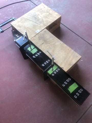
Wanted to fabricate my cable shifter but didn’t trust my skills, or at least in a timely manner. Went with the Cable Shift setup and pretty happy with it so far. The original adapter on the trans had one cable coming in at an angle that interfered with my trunk pan so I made some modifications. Here it is in a test setup to make sure it works while I still have some room to work on it. 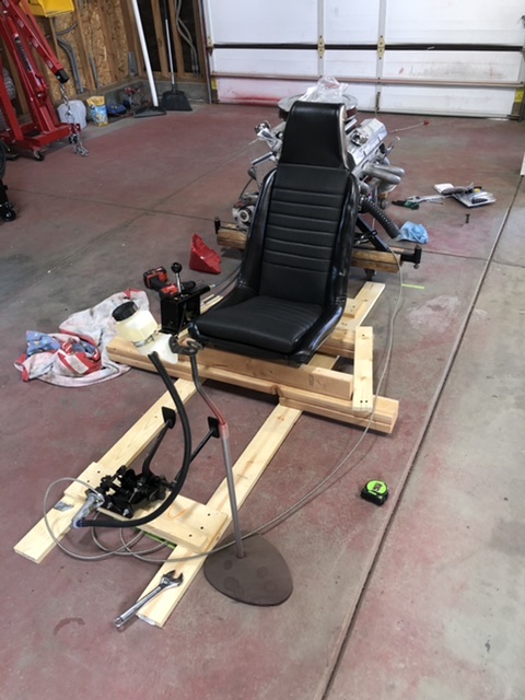
Reminds me of making a go kart as a kid 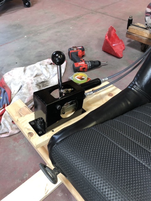
Shifter is a bit industrial for my preferences so I will spruce it up in the car. 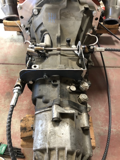
Hydraulic clutch seems to work well and can get into all the gears, except reverse. Not too concerned since i was able to before I mounted the trans to engine. Thinking it can be difficult without engine running.
Posted by: FL 000 Apr 3 2021, 05:41 PM
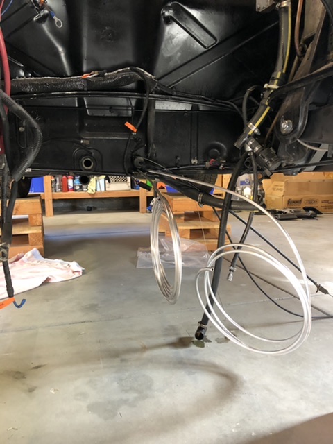
Got my fuel lines routed (mostly) also. Using aluminum line with AN fittings at tank and PFTE for final connection to engine. 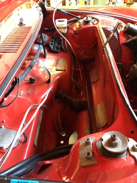
Posted by: 76-914 Apr 3 2021, 07:10 PM
Looking good. Should be ready for some summer runs.
Posted by: mgp4591 Apr 4 2021, 02:53 PM
Got my fuel lines routed (mostly) also. Using aluminum line with AN fittings at tank and PFTE for final connection to engine.
What are you looking to run for your clutch m/c reservoir?
Posted by: partwerks Apr 4 2021, 09:57 PM
I know there are a number of electric water pumps on the market, but the Davies Craig caught my eye and is the one I went with. Pretty slick little unit that uses pulse wave modulation (PWM) to hit the target temp, which should help on the efficiency side. It also has as a control module that allows you to set your target temp, and control the radiator fans. Set it and forget it in theory. Here it is installed
Yes that is a drop of water below it, yes it drives me nuts, and yes it will be fixed
The pump looks lower then it really is compared to the engine bar, but I am going to secure it with a mount higher to be safe.
I was pretty proud of these adapters I made, even though they don't look all that impressive! The tube was too thick to put a DIY bead in, so I welded a bead around it. Seems to be sealing good so far.
As I mentioned the waterpump uses PWM, which basically means cycling between off and on. For DC motors that is a better approach then say trying to control the RPM with varying voltage.
Because of this I was concerned my heater core would not see a consistent flow of hot water through it, and consequently may lead to inconsistent heat flowing out of the blower. Probably wouldn't have mattered, but I am a bit anal by nature so I decided to account for it.
I installed the booster pump shown in the previous post, and added an Arduino UNO to control it. I tapped into the potentiometer wire from the heater valve, and the more you turn the heat knob up the more the booster pump flows. This also seems to be working well.
I have the craig davies pump. Only problem I had, the first flanges had Porosity problems. Took a year till I got some replacements that actually didn't seep.
Posted by: FL 000 Apr 5 2021, 09:33 PM
What are you looking to run for your clutch m/c reservoir?
I am using this one from Wilwood. Going to mount it somewhere in the vicinity of the brake reservoir.
The rubber hose is crazy thick and don’t want to bore a huge hole under tank so making use of 3/8” aluminum tube and a hole that is already there. Will flare one end for hose to reservoir connection.
Posted by: FL 000 Apr 5 2021, 09:39 PM
I have the craig davies pump. Only problem I had, the first flanges had Porosity problems. Took a year till I got some replacements that actually didn't seep.
I noticed some of the designs have flanges that bolt to the pump body. I was concerned that could be a leak source also, and mine has the inlet/outlet formed into the body best I can recall.
I had the pump controller mounted in the center console, but my shifter cables will be in the way now. Need to find new location.
Posted by: FL 000 Apr 5 2021, 09:45 PM
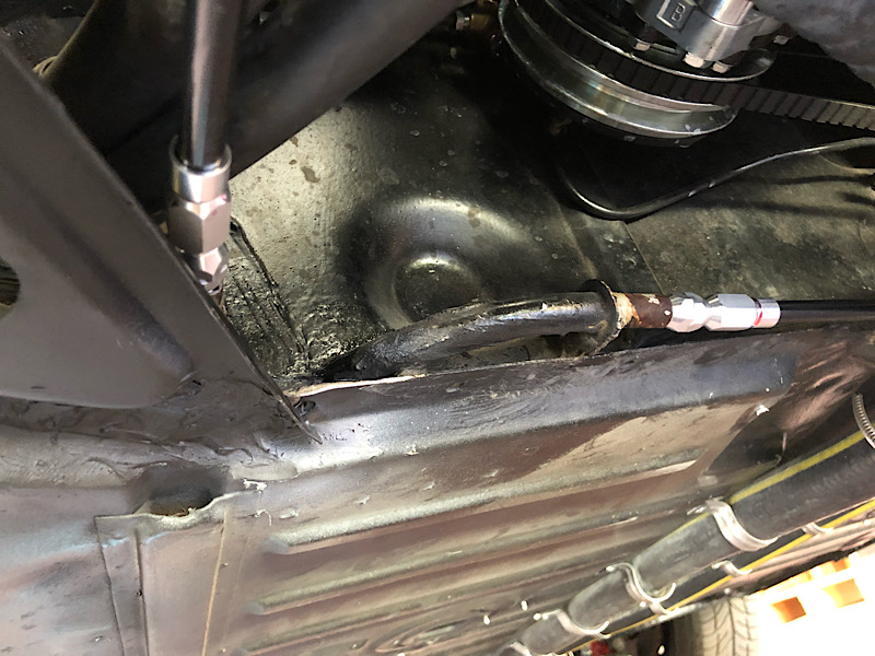
Clutch master installed and hose ran to engine compartment. Only a couple curse words blurted out too working in the confined space 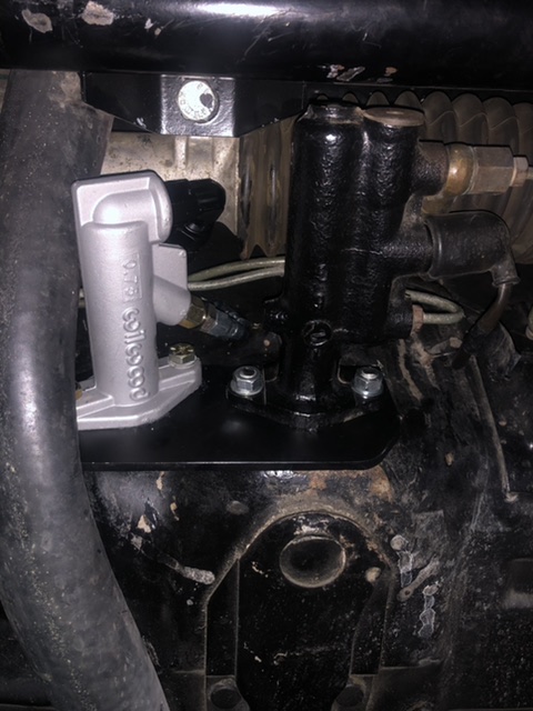
Posted by: 76-914 Apr 6 2021, 08:26 AM
What are you looking to run for your clutch m/c reservoir?
I am using this one from Wilwood. Going to mount it somewhere in the vicinity of the brake reservoir.
The rubber hose is crazy thick and don’t want to bore a huge hole under tank so making use of 3/8” aluminum tube and a hole that is already there. Will flare one end for hose to reservoir connection.
Not to highjack your thread but I'm using the same reservoir and this was the only location I found that worked for me. IIRC, I set it back ~1/2" for tank clearance.
http://www.914world.com/bbs2/uploads/post-9964-1604967786.jpeg
Posted by: FL 000 Apr 6 2021, 09:30 PM
Not to highjack your thread but I'm using the same reservoir and this was the only location I found that worked for me. IIRC, I set it back ~1/2" for tank clearance.
http://www.914world.com/bbs2/uploads/post-9964-1604967786.jpeg
@http://www.914world.com/bbs2/index.php?showuser=9964 By all means, highjack - you are saving me time in the long run!
That is pretty much where and how I planned to mount mine so thanks for the confirmation.
Posted by: FL 000 May 20 2021, 07:46 PM
Precarious position. I really need to get a lift. Done this about half a dozen times but always hold my breath in the process 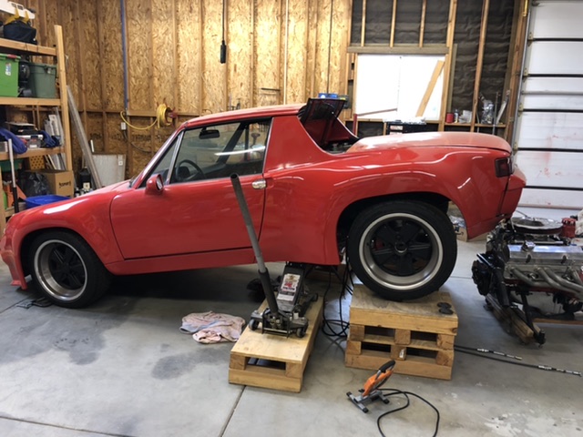
Safely back down. Time for a drink 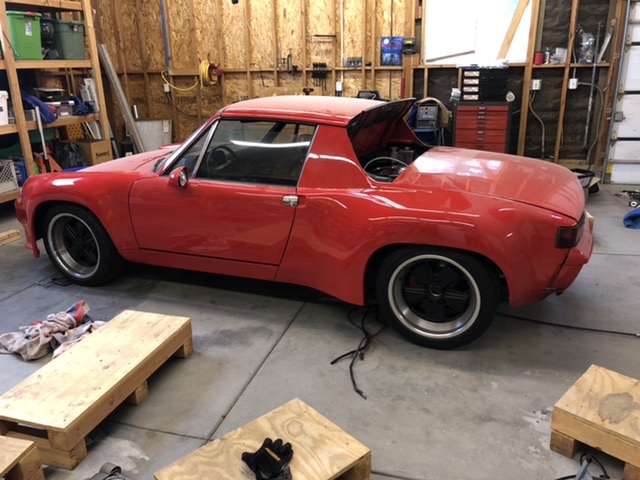
Posted by: FL 000 Jul 12 2021, 08:04 PM
Been a couple months since my last post but have been keeping busy. Working on like 5 different things at once so hard to show progress
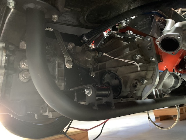
I made my cradle and got it installed. Tried to find someone local to bend my tubes but shops only had the pusher style. I was worried it would buckle the tube with the radius I was after, so I ended up buying a bender and put my son to work 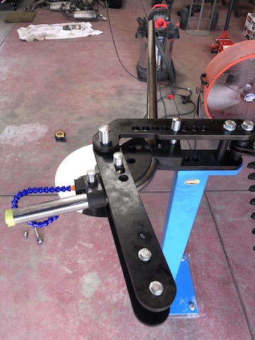
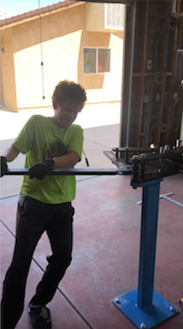
Pretty happy with how it turned out, and will keep an eye on it once driving to make sure everything stays together. I used 1/8" plate for the upper trans mount, and drilled hole in it to allow tube (0.120 wall) to pass through so I could weld from the top and bottom. The side mounts are 3/16" plate. A leaf spring tube kit with polyurethane bushings tie it together. 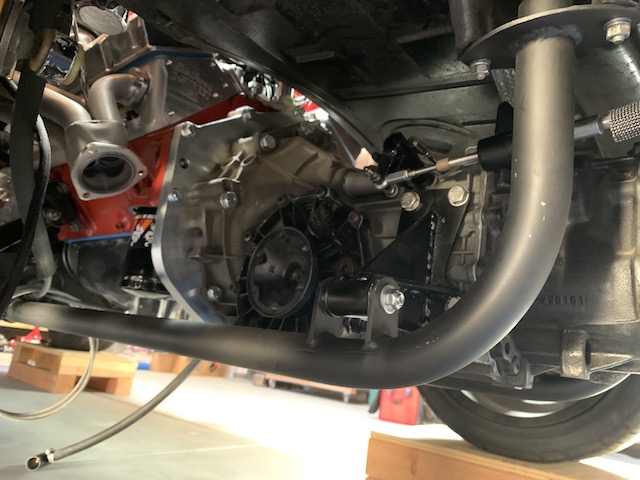
Posted by: FL 000 Jul 12 2021, 08:13 PM
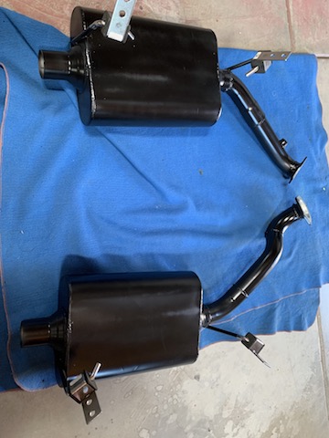
When I originally got my car on the road welding my own exhaust sounded way outside my reach with the tools and knowledge I had, so I had a shop do it. Still was a bit nervous this time around but went for it. Like most things tackling it one step at a time made it manageable. Old and new: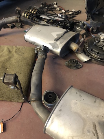
Posted by: 76-914 Jul 12 2021, 08:24 PM
Your "beginner job" looks more professional than the other guys work. Great job!
Posted by: FL 000 Aug 12 2021, 06:20 PM
Your "beginner job" looks more professional than the other guys work. Great job!
They turned out pretty well and are holding up good. You can definitely hear me coming so we will see if I stick with the Flowmasters long term.
Posted by: FL 000 Aug 12 2021, 06:29 PM
I need some motivation to make the final push so figured posting progress will help. I leave 8 Sept for Moab and this is what I want to have done more or less in order:
Speedhut gauges installed
Get miles on it
Front radiator ducting - in work
Center console
Rear trunk electronics panel cover
Rear trunk lid fiberglass repair
Alignment
I should receive my combo gauge Monday and can get that done mid-week. That will round out this package: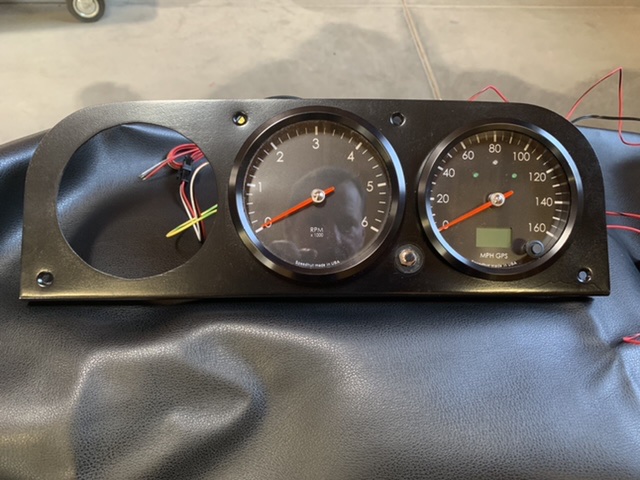
Posted by: FL 000 Aug 12 2021, 06:44 PM
I have added a lot of heat protection this go-around, and it has made a big difference in the engine compartment and rear trunk.
Up front I decided to contain the hot air so it goes out the wheel well vents and not into my gas tank and cab. Boom mat has been awesome for this area. Thick, light, and works well with the hot air blowing directly on it. My goal is to have close to zero metal exposed. 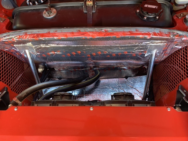
A thin gauge aluminum top will cover it, with mat underneath. I’ll paint it when able, but not a priority. 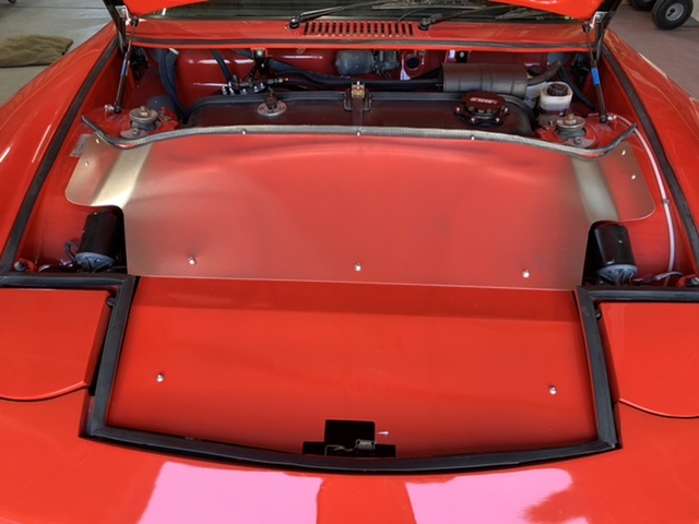
You can see the front side portions will need some extra care to seal. Messing around with 2 part foam, foam mat, and styrofoam to see what works but also looks decent. 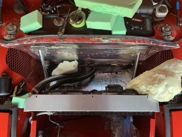
Posted by: FL 000 Aug 17 2021, 07:08 PM
Gauges aren’t quite done but done enough to show this. Still need to add the speedhut temp sensor and oil sending unit on engine, hopefully tomorrow. Thanks again to @http://www.914world.com/bbs2/index.php?showuser=19241 for the gauge panel! 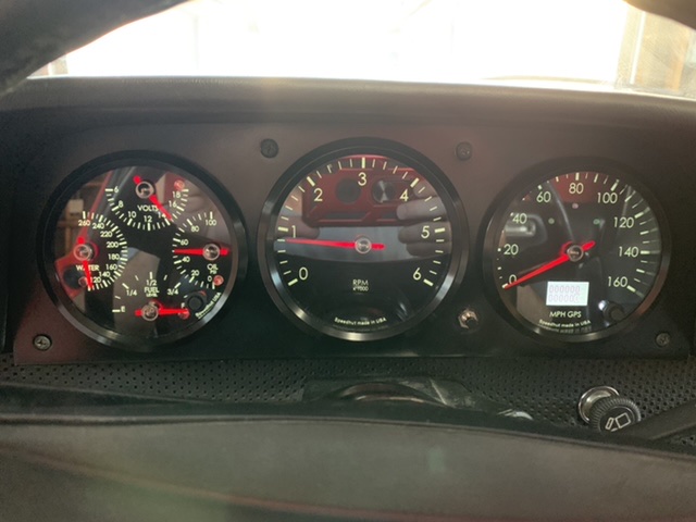
I will say it is nice having a tach that doesn’t bounce every time the RPM changes 
Posted by: FL 000 Aug 19 2021, 06:08 PM
Made my 70 mile round trip to work today! Drove great on the way there, but the way home was a little sketchy
About 2/3 of the way home I started having a hard time finding my gears. After a few minutes realized it was all the forward throw gears R 1 3 5. Got it home without a tow or burning my clutch 
After some investigation I think it is a fairly simple fix, with the problem appearing to be that the shift handle doesn’t have enough forward throw to engage the gears. An extra 1/16” is probably all I need.
Also both my fuses for my fans blew the last part of the drive. I have gone overkill on wiring gauge, but have some ideas on things to check. The wire connections are first on my list.
Posted by: 76-914 Aug 19 2021, 06:43 PM
Your gauges look great Josh. Chris @http://www.914world.com/bbs2/index.php?showuser=19241 knocked it out of the park with that panel. I like your idea to contain that "Box of Heat" with the thin gauge aluminum. Question; do your fans run in tandem or independently? What kind of amps are your fans pulling on start up vs warmed up?
Posted by: tygaboy Aug 19 2021, 06:57 PM
Great to hear things are coming along, sorry about the issues. You'll get that fixed in no time!
And your gauges do look really nice! 
Posted by: FL 000 Aug 21 2021, 08:58 AM
Your gauges look great Josh. Chris @http://www.914world.com/bbs2/index.php?showuser=19241 knocked it out of the park with that panel. I like your idea to contain that "Box of Heat" with the thin gauge aluminum. Question; do your fans run in tandem or independently? What kind of amps are your fans pulling on start up vs warmed up?
They are wired independently, but triggered to come on at the same time either from engine temp or A/C trinary switch. Each is controlled with a relay and 20 amp fuse. Same setup I had in my previous setup and never had this happen. I redid a bunch of my wiring while I was in there, but must have goofed something up. The fuses don’t blow immediately, just after some time.
IIRC my fans are rated for 15 amps at startup and 10 while running. Need to check that assumption, and not sure what my actual running amp draw is.
Posted by: FL 000 Aug 22 2021, 02:46 PM
The wife and I drove to Wrightwood for breakfast this morning. Beautiful weather and hardly anyone on the back roads.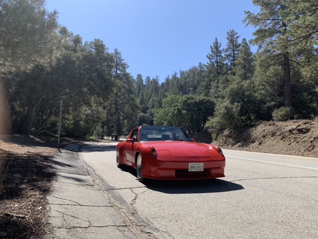
Posted by: FL000 Jul 30 2022, 06:51 PM
A little over 5000 miles on the 01E, then returning from WCR car coasted to a stop. My driver side output shaft hub was sticking out about an inch and trans fluid was leaking from it.
Finally got the inner half shaft unbolted today and the culprit was the center bolt backed out. Happy that it will be an easy fix but bummed I didn’t think to try and do a roadside repair. 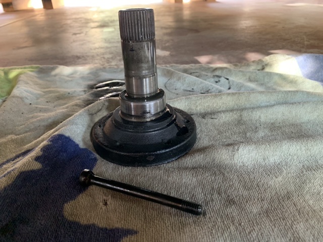
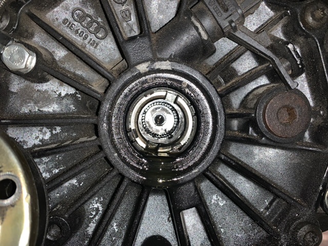
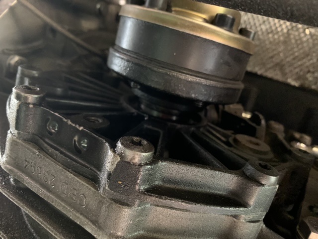
I’ll replace the seal for good measure, make sure the passenger side is torqued to spec, and maybe through on some blue locktite to boot.
In the future a jiggle test will be in order before a big trip.
Posted by: dan10101 Jul 30 2022, 07:08 PM
Such a bummer end to a great weekend. I had the outer stub shaft break on me at the dragstrip a couple months back. You're talking about the inner stub shaft right?
I think mine was loose a bit too. All I know is that it's tight now!
Get that sweet machine back on the road!
(and the track!) LOL
Posted by: tygaboy Jul 30 2022, 07:36 PM
Glad to hear it wasn't something "breaky"! And great meeting you both at WCR! Looking forward to seeing you again next year.
Posted by: FL000 Jul 30 2022, 07:40 PM
Such a bummer end to a great weekend. I had the outer stub shaft break on me at the dragstrip a couple months back. You're talking about the inner stub shaft right?
I think mine was loose a bit too. All I know is that it's tight now!
Get that sweet machine back on the road!
(and the track!) LOL
Ah, thanks Dan. Yes it was the inner stub shaft.
Posted by: FL000 Jul 30 2022, 07:43 PM
Glad to hear it wasn't something "breaky"! And great meeting you both at WCR! Looking forward to seeing you again next year.
You too - nice chatting with you and cool to see your beast in person and on the road.
Posted by: Cairo94507 Jul 31 2022, 07:31 AM
And he has air conditioning.... Seriously, a pleasure to meet you and your wife. Great car and I am sorry you ended up on a flatbed. We have all been there and that is no fun. Very glad it was an easy repair.
Posted by: FL000 Sep 2 2022, 06:16 PM
Rubber moulding around the windshield was looking worse for wear so I decided to go with the factory trim.
Windshield frame needed a refresh - prepping for paint. I feel like I just did this 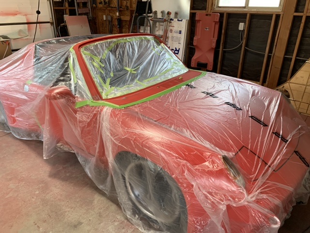
A little warm this time of the year and plan to spray bright and early tomorrow. 
Posted by: FL000 Sep 5 2022, 11:36 AM
A couple lessons learned but overall happy with how it came out. Next up get some miles on her and get windows tinted before RRC. Going with ceramic to see if it can help cut the cabin heat. 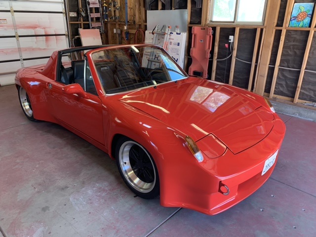
Posted by: tygaboy Sep 5 2022, 12:06 PM
Josh - that looks great! Feel free to come paint my car...
Here's to a safe and no issues RRC. Enjoy and take lots of pics for all of us who can't be there.
Posted by: Cairo94507 Sep 5 2022, 12:39 PM
That really looks nice- love the stock windshield trim. Safe trip and fun on the RRC trip. Oh, and you are going to go with a ceramic tint....'cause the AC is not enough cooling.... some people have all the luck.
Posted by: mxkinn01 Sep 5 2022, 12:45 PM
A couple lessons learned but overall happy with how it came out. Next up get some miles on her and get windows tinted before RRC. Going with ceramic to see if it can help cut the cabin heat.
Josh,
Is that over spray I see on your garage door? LOL Car looks great. We'll see you at the RRC in a few weeks, hopefully its cooler weather in Salt Lake City.
Mike
Posted by: FL000 Sep 5 2022, 03:14 PM
@http://www.914world.com/bbs2/index.php?showuser=19241 will do on the pics of RRC. I would be nervous turning a wrench on your car let alone painting it! The beauty of working on my car is if I screw it up I only have myself to blame. I am looking forward to seeing what yours looks like when complete. Over the top, subtle,
@http://www.914world.com/bbs2/index.php?showuser=9712 I am careful not to boast among fellow teeners, but it is nuts when you feel cold air from the vents and the sun still manages to cook you lol.
@http://www.914world.com/bbs2/index.php?showuser=21195 I am sure you are wondering how in the hell I got overspray there. I tape some paper there and adjust the gun before I hit the car. Guess I need more
Am I the only one who didn’t realize these cars use an adhesive pad to attach the rear view mirror to the windshield?! I ended up use Permatex from the FLAPS but have a pad on order if/when it falls off.
Posted by: 76-914 Sep 6 2022, 07:38 AM
I just removed my rear view mirror which I Permatex'ed on back in 2009. I thought it would never come off!
Powered by Invision Power Board (http://www.invisionboard.com)
© Invision Power Services (http://www.invisionpower.com)