Printable Version of Topic
Click here to view this topic in its original format
914World.com _ 914World Garage _ Distributor Shaft Alignment
Posted by: Gatornapper Dec 14 2019, 08:40 PM
Haynes Manual, page 65, Fig. 3.6, referenced from page 64, Pp. 6, #7: "install it so that.........an angle of 12 deg. .......with the small sector facing towards the outside of the car."
On my 914, the small sector is on the left.
If I'm reading this correctly, this is ambiguous and does not clarify it "the outside of the car" is the Driver's side or Passenger side.......
Can someone clarify this please? Or am I missing something (not the first time...).....
TIA,
GN
Posted by: Garland Dec 15 2019, 12:18 AM
Check out this post.
http://www.914world.com/bbs2/index.php?showtopic=7934
Replying to Distributor Shaft Alignment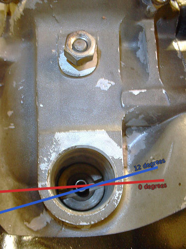
Posted by: Gatornapper Dec 15 2019, 07:02 AM
Thank you.
So, how did mine get about 180 degrees out of sync?
Did a large backfire destroy the drive gear?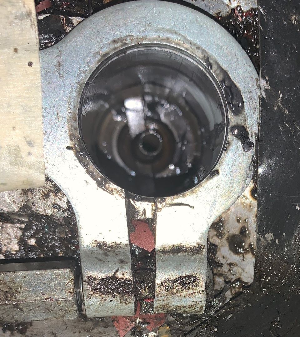
??????????

Check out this post.
http://www.914world.com/bbs2/index.php?showtopic=7934
Replying to Distributor Shaft Alignment
Posted by: Gatornapper Dec 15 2019, 07:15 AM
Thanks Garland.....
Perhaps I'm not on TDC, not on compression stroke - but one rev out...
Will check later today......
GN
Posted by: Superhawk996 Dec 15 2019, 10:15 AM
Thanks Garland.....
Perhaps I'm not on TDC, not on compression stroke - but one rev out...
Will check later today......
GN
It is not possible for a backfire to destroy the gear interface between the crank and the distributor.
Easiest way is to pull valve cover. Look at the valves. When both are closed and you're at TDC you know your on the compression stroke. There is no possibility of being 180 out if both valves are closed.
Setting aside all other nonsene of manual, if you set to TDC #1 based on piston and valve position, and then align the distributor into the notches such that the rotor is pointing at Cylinder #1 spark plug terminal, it will be correct.
Posted by: Gatornapper Dec 15 2019, 12:37 PM
Ok, #1 is at TDC, and this is the position of the rotor - between cap towers - not under a tower. Because of the off-set on the groove in the dist shaft and the dist. base, this is the only way it will go in.
This is also with the points set by static timing immediately after light went on, slowly turning dizzy CCW......i.e., dizzy was inserted initially with point of rotor on mark on top wall of dizzy, and has been rotated CCW from that point. Splines of dizzy base are fully inserted in shaft.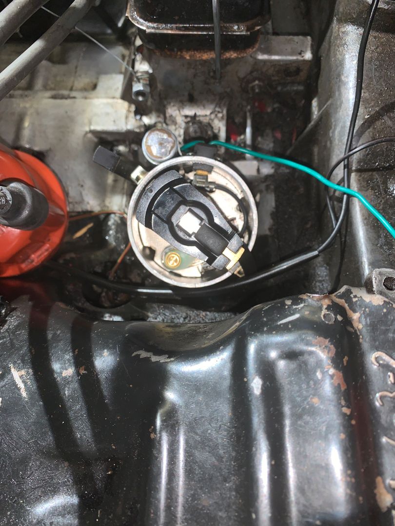
How can this be?
If I remember correctly, when engine was running well, the #1 cap tower was at about 11 o'clock from the rear facing the front of the car. About 80 deg. CCW from where it is now.........
What changed it's orientation?
GN
Posted by: sixnotfour Dec 15 2019, 12:43 PM
non bosch rotor make sure it actually is push into the notch on the shaft...pull off and double check..
Posted by: Gatornapper Dec 15 2019, 12:47 PM
non bosch rotor make sure it actually is push into the notch on the shaft...pull off and double check..
Done. Will put Bosche rotor back on.
Posted by: Garland Dec 15 2019, 01:04 PM
Are you sure you’re getting the distributor housing, passed the hold down clamp, and seated to the block?
Posted by: Superhawk996 Dec 15 2019, 01:06 PM
This is also with the points set by static timing immediately after light went on, slowly turning dizzy CCW......i.e., dizzy was inserted initially with point of rotor on mark on top wall of dizzy, and has been rotated CCW from that point.
@http://www.914world.com/bbs2/index.php?showuser=21449
I'm a bit confused by your statement that you set static timing immediately after the light went ON.
Your test light should be fed by +12v. The ground circuit is completed by the points.
When the points are closed, the light is ON.
Static timing is set by rotating the distributor until the light goes OFF and the points have just begun to OPEN.
The ignigiton fires off spark when the points OPEN. Thus, the point at which the light turns OFF is what you're intested in when setting the static timing.
Posted by: Superhawk996 Dec 15 2019, 01:41 PM
This is also with the points set by static timing immediately after light went on, slowly turning dizzy CCW......i.e., dizzy was inserted initially with point of rotor on mark on top wall of dizzy, and has been rotated CCW from that point.
@http://www.914world.com/bbs2/index.php?showuser=21449
I'm a bit confused by your statement that you set static timing immediately after the light went ON.
Your test light should be fed by +12v. The ground circuit is completed by the points.
When the points are closed, the light is ON.
Static timing is set by rotating the distributor until the light goes OFF and the points have just begun to OPEN.
The ignigiton fires off spark when the points OPEN. Thus, the point at which the light turns OFF is what you're intested in when setting the static timing.
Note: As I thought about this more, you could configure the light to work either way depending on how you wired the light in.
The method above is what has always worked for me where I use the points to break the circuit and turn the light OFF. Actually, I don't even use a light. I just measure the resistance across the points with a DMM but the principle is the same. Regarless, the coil always fires off the spark when the point open.
Posted by: rjames Dec 15 2019, 02:25 PM
Maybe I’m missing something... Is the rotor is pointing at #1 when it is tdc? If yes, tighten the dizzy, but not too tight. From there, check that the points gap is correct.
Set the dwell 44-45 degrees and you are ready to start the car and then set dynamic timing.
Points and dwell must be set right for the car to start.
There is also a mark on the flywheel that you can see from engine bay that indicates tdc for #1 if you pry back the engine tin/seal a bit.
Posted by: Gatornapper Dec 15 2019, 07:27 PM
SH -
MY BAD! My brain was not plugged in yesterday and the part that was plugged in was dyslexic!
I knew all that, but wasn't thinking clearly.
Had just a few minutes today to set points correctly, and rotor is directly under tower to #1, which, facing the front of the car and the firewall is between 1 and 2 o'clock on the dist. cap. with the engine on TDC.
Will attempt to start tomorrow....too busy today.....
Thanks for pointing out my gross error. Sometimes I'm an idiot.
GN
This is also with the points set by static timing immediately after light went on, slowly turning dizzy CCW......i.e., dizzy was inserted initially with point of rotor on mark on top wall of dizzy, and has been rotated CCW from that point.
@http://www.914world.com/bbs2/index.php?showuser=21449
I'm a bit confused by your statement that you set static timing immediately after the light went ON.
Your test light should be fed by +12v. The ground circuit is completed by the points.
When the points are closed, the light is ON.
Static timing is set by rotating the distributor until the light goes OFF and the points have just begun to OPEN.
The ignigiton fires off spark when the points OPEN. Thus, the point at which the light turns OFF is what you're intested in when setting the static timing.
Posted by: Gatornapper Dec 15 2019, 07:34 PM
Thanks!
I have previously marked the following on both the front side of the impeller where you can see it and the flywheel:
TDC (black), 7.5 deg. BTDC (white), and 27 deg. BTDC (red).
GN
Maybe I’m missing something... Is the rotor is pointing at #1 when it is tdc? If yes, tighten the dizzy, but not too tight. From there, check that the points gap is correct.
Set the dwell 44-45 degrees and you are ready to start the car and then set dynamic timing.
Points and dwell must be set right for the car to start.
There is also a mark on the flywheel that you can see from engine bay that indicates tdc for #1 if you pry back the engine tin/seal a bit.
Posted by: cary Dec 16 2019, 12:47 AM
You got this. When you are CERTAIN you are at TDC on #1 re orient the dizzy drive. With McMark's 12 degree image you'll have #1 back in the 1 o'clock position.
Three pieces come out. Spring. Dizzy Drive, most important the oiler washer. McMark's write up is outstanding.
Superhawk996
Easiest way is to pull valve cover. Look at the valves. When both are closed and you're at TDC you know your on the compression stroke. There is no possibility of being 180 out if both valves are closed.
http://www.914world.com/bbs2/index.php?s=&showtopic=7934&view=findpost&p=105399
Posted by: 914_teener Dec 16 2019, 10:37 AM
You got this. When you are CERTAIN you are at TDC on #1 re orient the dizzy drive. With McMark's 12 degree image you'll have #1 back in the 1 o'clock position.
Three pieces come out. Spring. Dizzy Drive, most important the oiler washer. McMark's write up is outstanding.
Superhawk996
Easiest way is to pull valve cover. Look at the valves. When both are closed and you're at TDC you know your on the compression stroke. There is no possibility of being 180 out if both valves are closed.
http://www.914world.com/bbs2/index.php?s=&showtopic=7934&view=findpost&p=105399
Clean out the dizzy bore. It's a clearance fit but that gunk you've got on the case could be problematic.
Just sayin.
Posted by: Gatornapper Dec 16 2019, 08:58 PM
Like some help checking my reasoning here:
Dizzy rotates 1/2 rotation per each full rotation of crankshaft.
On dizzy driveshaft ("DD"), if TDC mark is seen on flywheel or impeller in the notch, and the slot in the DD has the small segment on the right, and is at 12 deg. CCW of vertical, the DD is in the TDC for the compression/fire stroke....as in Garland's Post 2.
OTOH, if the TDC mark is seen on the flywheel or impeller in the notch, the slot on the DD will still be 12 deg. CCW of vertical, but the small segment will be on the LEFT side of the DD.....as in my Post 3. But the TDC will be for the exhaust stroke - not the fire stroke.
Correct?
Posted by: injunmort Dec 17 2019, 06:09 PM
in your picture, you are not timed on #1. that is #4. #1 from the back of the car is trans left side. 1 next to it is 2(by chimney left side, 3 trans right side , 4 is chimney , right side. by that pic you are 180 out. can be done with better grasp of system. go by book. put #1 on tdc compression (both rockers on #1 loose) check your fan mark, should be in aperture. clock your dist so that the rotor is pointed at the #1 spark plug. you may need to take out drive pinion and turn it 180 degrees. now set points by rotating dist. until points just break. that is it. next is setting with light while running.
Posted by: rhodyguy Dec 17 2019, 06:51 PM
If the engine is at TDC on #1, and the dist drive is out 180*, for sure, then if you install the distributor, where ever the rotor is pointing would be #1 TDC. Mark that spot on the distributor body lip. If the drive is out 180* the wires are off 180*. The cap only goes on one way.
Posted by: Gatornapper Dec 18 2019, 10:02 AM
That was old pic, I realized it was incorrect. It has been corrected. Thought I had stated that.
Rotor now on #1. With #1 on TDC compression stroke.
Did static timing at that point, but engine still will not start.
in your picture, you are not timed on #1. that is #4. #1 from the back of the car is trans left side. 1 next to it is 2(by chimney left side, 3 trans right side , 4 is chimney , right side. by that pic you are 180 out. can be done with better grasp of system. go by book. put #1 on tdc compression (both rockers on #1 loose) check your fan mark, should be in aperture. clock your dist so that the rotor is pointed at the #1 spark plug. you may need to take out drive pinion and turn it 180 degrees. now set points by rotating dist. until points just break. that is it. next is setting with light while running.
Posted by: Gatornapper Dec 18 2019, 10:04 AM
My bad, as I said. I had put dizzy in when engine was at TDC exhaust stroke.
Has been corrected. As have the cap wires - all are correctly oriented now.
If the engine is at TDC on #1, and the dist drive is out 180*, for sure, then if you install the distributor, where ever the rotor is pointing would be #1 TDC. Mark that spot on the distributor body lip. If the drive is out 180* the wires are off 180*. The cap only goes on one way.
Posted by: Gatornapper Dec 18 2019, 01:05 PM
SuperHawk -et al -
"Easiest way is to pull valve cover. Look at the valves. When both are closed and you're at TDC you know your on the compression stroke. There is no possibility of being 180 out if both valves are closed."
Please bear with me here. I know this is the normal way to determine TDC on the compression stroke - I have used this method for decades. But usually the valves can be more easily accessed than they are on the 914 engine.
But I believe there is an easier way - and if I am wrong, would love for anyone to explain to me why.
When the engine is on TDC of the compression stroke, the rotor will be in only one possible position, with a few degrees difference allowing for differences in timing.
When the engine is on TDC of the exhaust stroke (1 revolution from TDC compression), the position of the rotor in the dizzy will be 180 degrees (1/2 revolution) from where it is on the compression stroke. I.e., pointed in the opposite direction. How can it be otherwise?
If true, then one should be able to tell whether the engine is on the compression TDC by seeing where the rotor is positioned when the spark fires.
Next question: shouldn't all Type 4 engines have the rotor pointing in the same direction (within a few degrees) when cylinder/plug #1 fires?
Thanks for the patience and forebearance with my questions.
GN
Thanks Garland.....
Perhaps I'm not on TDC, not on compression stroke - but one rev out...
Will check later today......
GN
It is not possible for a backfire to destroy the gear interface between the crank and the distributor.
Easiest way is to pull valve cover. Look at the valves. When both are closed and you're at TDC you know your on the compression stroke. There is no possibility of being 180 out if both valves are closed.
Setting aside all other nonsene of manual, if you set to TDC #1 based on piston and valve position, and then align the distributor into the notches such that the rotor is pointing at Cylinder #1 spark plug terminal, it will be correct.
Posted by: sixnotfour Dec 18 2019, 01:18 PM
boxer engine so 1 of 2 cyl.s can be at TDC... what you say is correct if everything is correct, your having troubles , so its best to start at square one......
There is a six build where 2 shops could not figure out why it ran so low on HP and acted strange,
The engine was tore apart ..but after reading what the symptoms where , and what nobody ever did was check the cam timing. on a six its easy to time one cam 180 out, runs , half power and does some minor weird things,,,Just an example of not starting at square one 
Posted by: Gatornapper Dec 18 2019, 02:44 PM
Thank you.
Totally agree - trying to get to ground zero.
Tell me this: how can an engine be running PERFECTLY one day, the next day is missing, backfiring, barely running; then for a week starts immediately and runs perfectly for just under a minute - then quits and will not re-start; then won't start at all - and distributor position has changed - when no one has touched the engine?
Same fuel was in tank for 2 weeks until after a week of not starting I "went to ground zero" on fuel system completely purging system, new fuel filters, 2nd one added just before carbs, perfect 3psi fuel pressure - then I conclude problem is ignition.
Most ignition is brand new, so I make it all brand new. Still won't start.
GN
boxer engine so 1 of 2 cyl.s can be at TDC... what you say is correct if everything is correct, your having troubles , so its best to start at square one......
There is a six build where 2 shops could not figure out why it ran so low on HP and acted strange,
The engine was tore apart ..but after reading what the symptoms where , and what nobody ever did was check the cam timing. on a six its easy to time one cam 180 out, runs , half power and does some minor weird things,,,Just an example of not starting at square one
Posted by: Gatornapper Dec 18 2019, 02:47 PM
Question:
Is this not the correct position for the rotor on every 914 for TDC on #1?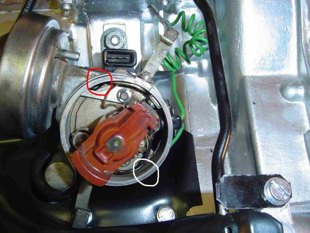
GN
Posted by: sixnotfour Dec 18 2019, 04:30 PM
rotate your distributor to line up with rotor,,, you will be close, if at tdc #1
Posted by: theer Dec 18 2019, 04:40 PM
Question:
Is this not the correct position for the rotor on every 914 for TDC on #1?
GN
With a stock dizzy, I believe you are correct.
I had a helluva time trying to figure out 1-3-4-2 wire orientation on an 009 or 050 cap, where the rotor didn't point in the same direction as stock.. the mark on the case was at a different spot on the dizzy case, so TDC was clear, but the wires needed to be properly oriented on the cap.
Posted by: Gatornapper Dec 18 2019, 07:47 PM
Did that some time ago.
Engine is firing #1 when rotor is under the #1 tower, and timing light verifies that at starting rpm - firing is occurring at TDC where I did static set of timing.
BUT, whereas my #1 tower was located exactly as in the photo in post #25 a month ago, it is now located as in the pic in post #6, about 80 deg. clockwise of the pic in post #25. The distributor driveshaft has not been touched. and the slot in the DD and the dizzy can only fit in one way.
How did that change occur?
TIA,
GN
rotate your distributor to line up with rotor,,, you will be close, if at tdc #1
Posted by: rhodyguy Dec 18 2019, 08:18 PM
is that a picture of the distributor in your car?
Posted by: theer Dec 18 2019, 08:25 PM
Sorry in advance if I’m missing something or if this is obvious... but the dizzy in post 6 is different from the one in post 25. Post 25 looks stock (with vacuum advance); post 6 has no vacuum can, might be an 009 or 050 centrifugal advance. This is exactly what I was talking about in my post above.
So, first make sure you have the right cap for your dizzy (again sorry if obvious)
The rotor position is fixed once the dizzy is locked in, so turn the base (and with it the cap) so that the rotor points at the #1 tower/wire at TDC. Then make sure the other wires follow in firing order around the cap. IIRC, the centrifugal advance dizzy needs more advance than stock.
Posted by: rhodyguy Dec 18 2019, 09:50 PM
The one pictured that has the circles is for a Djet system. A Ljet dist has no trigger point wiring provision. You want a part number ending in AB. I'm confused.
Posted by: Gatornapper Dec 19 2019, 08:58 AM
Post 6 is mine - BEFORE I got the body rotated properly - BUT the position of the rotor did not change, as that is determined by the position of distributor driveshaft.
The pic on post 25 I got off this forum as I wanted a pic not of the distributor but of the rotor position at TDC. Yes, the distributor is different, but I am not concerned with that. My dizzy is a 178 009 that apparently the Porsche dealer put int when they installed the Webers and many say is not good for this engine. I am soon replacing it with a nice 1.8 dizzy I just got off eBay that has vacuum advance. It is an 0 231 181 009/022 905 205 AA.
No one has yet answered my question of the position of the rotor at TDC - it must be the same on all 914 - 4's as I see it, and I believe it, when facing the front of the car from the rear, should point to about 11 o'clock, and that's where the cap tower to Plug #1 must also be at TDC. That's where it is in the pic I posted on post #25 and the reason I posted that pic.
I believe that is where my #1 cap tower was located before I started having engine problems. But now, at TDC, the rotor is pointed to about 1 o'clock.
HOW DID IT CHANGE? Could the gear on the bottom of the dizzy shaft slip? I cannot see how it could.
And is not 11 o'clock (from the rear) the position of all rotors and the #1 cap tower on all 914's?
TIA,
GN
The one pictured that has the circles is for a Djet system. A Ljet dist has no trigger point wiring provision. You want a part number ending in AB. I'm confused.
Posted by: injunmort Dec 19 2019, 09:13 AM
this last pic of rotor has it pointed at #2. that is not where it should be to static time. your tins are stamped with each cylinder # and the firing order is stamped up on right side tin by fan housing. use the factory stampings for position, don't reinvent the wheel. put engine at tdc on cyl #1. timing mark on fan and flywheel should be in the apertures. clock distributor so that rotor is pointing at cyl #1. ( 1 position back from in the photo) set your points at this point and you should be close. you only need to time one cylinder correctly then the engineering magic occurs on the other three. forget about the marks on the distributor body, the rotor contact is the index.
Posted by: Superhawk996 Dec 19 2019, 11:04 AM
Thank you.
Totally agree - trying to get to ground zero.
Tell me this: how can an engine be running PERFECTLY one day, the next day is missing, backfiring, barely running; then for a week starts immediately and runs perfectly for just under a minute - then quits and will not re-start; then won't start at all - and distributor position has changed - when no one has touched the engine?
GN
I'm going to stick my neck out with a crazy theory. Distributor was never properly engaged to the drive. Thermal expansion may have had it "hooked" properly and then when temperature changed, it disconnnected and "changed" its position despite no one touching it.
Way out there, but, if it actually did move out of time, with no one touching it, either the pinch bolt was loose, or the distributor drive was never properly engaged to the gear driven piece below it.
Also check the bottom of the distributior "cog", tang, drive, or whatever you want to call it. Make sure that is pinned to the rotor shaft. I don't have one in front of me but I think there is a roll pin or something in there to hold that "cog" to the distributor shaft.
DO NOT assume the gear driven piece down in the case below the distributor is set correctly. That installs 1st before the distributor. That gear driven directly off the crank is what determines the timing relationship. If the gear is in wrong, you'll never get the distributor rotor itself into the right position.
Posted by: theer Dec 19 2019, 02:25 PM
No one has yet answered my question of the position of the rotor at TDC - it must be the same on all 914 - 4's as I see it, and I believe it, when facing the front of the car from the rear, should point to about 11 o'clock, and that's where the cap tower to Plug #1 must also be at TDC. That's where it is in the pic I posted on post #25 and the reason I posted that pic.
I believe that is where my #1 cap tower was located before I started having engine problems. But now, at TDC, the rotor is pointed to about 1 o'clock.
HOW DID IT CHANGE? Could the gear on the bottom of the dizzy shaft slip? I cannot see how it could.
And is not 11 o'clock (from the rear) the position of all rotors and the #1 cap tower on all 914's?
The answer is NO. The rotor in the 009 points to different "clock" position than the rotor in a stock dist. It's still the #1 cylinder, though, so all that matters is that you have the wires matched up to the rotor's position underneath.
Hope that helps.
Posted by: injunmort Dec 19 2019, 05:13 PM
I don't know what you guys mean by different clock position?
tdc, compression on #1 is only one place, valves closed, tdc, timimg marks on both fan and flywheel in the holes visable. I just put a new 009 in an engine today, goes in same way as any other dist. rotor pointing at #1, points just breaking. there is no way to accurately line up the dist position with any marks on distributor body. cap only fits on one way (actually 2 ways 180 degrees apart but not relevant here) with rotor pointing at #1, put cap on, wire socket on cap wire goes to cyl #1. the rest of the wires are installed to corresponding cylinders following firing order on top right of tin. don't try to make cap what you think is tdc, set the enginge at tdc on 1, set points, install cap, install wires in firing order. its real simple.
Posted by: Gatornapper Dec 19 2019, 07:06 PM
Dear friend Mort -
I totally understand what you are saying - and have ever since I started working on this engine in July. I know well the cylinders and the firing order - they are both stamped on the engine tins. I have been a mechanic for 50 years. I do appreciate your attempts to help.
I think you are not understanding what I am trying to communicate. If that is so, the problem may be that I am not making clear what the situation is. I have already done exactly what you described in your post.
When I put the engine on TDC for #1, the rotor is in the 1 o'clock position. I cannot change that - it is determined by the slot on the distributor driveshaft and the offset part of the bottom of the dizzy. That is where the plug fires doing a static setting of the timing. With the points gap set at .016".
Why is the rotor in the wrong position? If I remember correctly, when the engine was running perfectly, the #1 plug wire was on the tower in the 11 o'clock position, as in the pic on Post 25 (NOT my dizzy). However, I did not record its position as the engine was running well and it was a non-issue. I replace all the ignition parts except the coil in July.
I have never touched the dizzy driveshaft, but it appears to be in the wrong position.
The tower the rotor should point to is the one at the 11 o'clock position when #1 fires - agreed? (my "o'clock" references are based on 12 o'clock being the part of the distributor being closest to the firewall). I
How can the position of the rotor when cylinder #1 is at TDC change?
Unless a gear on the dizzy driveshaft has slipped or moved? And I understand that that cannot happen.
I hope I am making sense - I am sure trying the best I can.
GN
this last pic of rotor has it pointed at #2. that is not where it should be to static time. your tins are stamped with each cylinder # and the firing order is stamped up on right side tin by fan housing. use the factory stampings for position, don't reinvent the wheel. put engine at tdc on cyl #1. timing mark on fan and flywheel should be in the apertures. clock distributor so that rotor is pointing at cyl #1. ( 1 position back from in the photo) set your points at this point and you should be close. you only need to time one cylinder correctly then the engineering magic occurs on the other three. forget about the marks on the distributor body, the rotor contact is the index.
Posted by: injunmort Dec 19 2019, 07:26 PM
if I am understanding you correctly, you say rotor is 11 o'clock position when timed at tdc on number 1 cylinder. that is incorrect, rotor should be at 7 o'clock position on tdc cylinder 1( pointing at spark plug in clylinder 1.) now if you are tdc on clinder 1 and that pic shows rotor loacation, you can time it there by making that wire your #1 wire. following firing order after. I just use the factory positions to keep it simple. you can change the position of the rotor by pulling distributor AND distributor drive from the motor. the drive is slotted and the distributor only fits it in the proper orientation. I pull both, pull cap, turn rotor to face cylinder 1 and then put both pieces in together. that gets the correct orientation. even if they separate during re install, it is close enough to be adjusted by turning dist body, then set the points, cap and reinstall wires.
Posted by: Gatornapper Dec 19 2019, 07:26 PM
PS: I have verified with my timing light that #1 IS FIRING at TDC when the engine is cranking.
Posted by: Gatornapper Dec 19 2019, 07:39 PM
Mort -
Thank you.
"if I am understanding you correctly, you say rotor is 11 o'clock position when timed at tdc on number 1 cylinder"
No. Currently the rotor is at the 1 o'clock position when #1 fires. I thought it used to be at 11 o'clock when the engine was running well.....but I don't know for sure as I never recorded its position. It may well have been in the 7 o'clock position as I never really noticed where it was - as the engine ran great (once I got the Weber's dialed in).
If it should be at the 7 o'clock position (12 o'clock being closest to firewall), how did it get 180 deg. out of position? That would be 1 revolution of the engine -
Another question that will help me greatly:
Please look at Garland's pic in Post #2. Is that a photo of the dizzy driveshaft at TDC for cylinder #1? The "0" degrees noted in that pic is what I am referencing at 12 o'clock.
Thank you for your patience........
GN
if I am understanding you correctly, you say rotor is 11 o'clock position when timed at tdc on number 1 cylinder. that is incorrect, rotor should be at 7 o'clock position on tdc cylinder 1( pointing at spark plug in clylinder 1.) now if you are tdc on clinder 1 and that pic shows rotor loacation, you can time it there by making that wire your #1 wire. following firing order after. I just use the factory positions to keep it simple.
Posted by: injunmort Dec 19 2019, 07:59 PM
cant tell what position that is without looking at timing marks on engine. that pic shows dist DRIVE in engine. I take that out when static timing the engine so I know it goes back in with the correct orientation.
Posted by: Gatornapper Dec 19 2019, 08:09 PM
In the Haynes manual on p. 65, Figure 3.6, there is a similar photo to Garland's pic on Post 2 - BUT, in the Haynes photo I cannot tell whether the "small segment" of the dizzy driveshaft is to the right of center or to the left of center. It clearly says this is the position at TDC.
In Garland's photo, clearly the "small segment" of the dizzy driveshaft is to the right of center. This is how it was when I inserted the dizzy last week.
Now follow me on this please: If Garland's pic is where the dizzy driveshaft is at TDC of #1 on compression stroke, then on the exhaust stroke TDC the dizzy driveshaft would be 1/2 revolution (1 full engine revolution) from the TDC compression stroke - putting the "small segment" of the shaft on the left side of the shaft center.
Does that make sense?
Posted by: injunmort Dec 19 2019, 08:52 PM
I think you are missing somethings. that drive and its orientation is determined when installed. you can take that out and rotate it, put it back in and all you have done is change the clocking of dist. the engine needs to be at tdc, compression on #1. verified by timing marks on fan/flywheel. then you can pull the drive out, orientate it to where the distributor shaft teeth mesh with the drive shaft sockets. turn the shafts so the rotor points at cylinder #1 and drop back in. there is no ,fixed position on the drive sprocket it slide in with slots oriented wherever you put them. depending that it was right before or you didn't mess with it is not enough, you need to completely static time the engine and this is part of the process.
Posted by: injunmort Dec 19 2019, 09:10 PM
many years ago I was restoring an early 1930's Norton. the timing chest was not marked. meaning no timiing marks on cam wheels or crank. fortunately, the stroke positions were available at the time. timing the cams, crank and ignition had to be done on the bench with a degree wheel, straight edge, caliper, and ruler. then the ignition was timed on the mag. fortunately for us, porshe marked those positions to alleviate that. use the timing marks to set ignition timing, makes it a lot simpler.
Posted by: Gatornapper Dec 19 2019, 09:23 PM
Again, bro - I totally get that. The dizzy driveshaft can be installed in a number of positions.
But is not the position of the dizzy driveshaft as originally installed and correct for TDC on #1 in the photo in Post #2?
If so, does that not position the rotor as it is shown in the pic on Post #25?
I have not touched mine ever. And a month and a half ago, the car was running perfectly. And had been running fairly well from when I first started it after 14 years in July. Of course before starting it I completely rebuilt both the fuel and ignition systems. And a couple tablespoons of Marvel Mystery oil sat in the cylinders for a month before I even cranked engine. It started immediately after 14 years - AND - NO SMOKE!
But I never removed the dizzy until after the engine totally quit running about Nov. 11th. I had no reason to touch it.
I do not want to touch the distributor driveshaft.
Now, I guess I could rotate the dizzy (NOT the driveshaft) 90 deg. counter-clockwise and then have #1 firing on the dizzy cam lobe to the left of the one it fires on now. But it seems to me that would change nothing but the position of the #1 cap tower in relation to the engine orientation.
Again, right now #1 is firing on TDC exactly - both shown on static light and timing light.
I'll take a pic tomorrow of my dizzy cap orientation for #1 plug wire.
Thanks.......
GN
I think you are missing somethings. that drive and its orientation is determined when installed. you can take that out and rotate it, put it back in and all you have done is change the clocking of dist. the engine needs to be at tdc, compression on #1. verified by timing marks on fan/flywheel. then you can pull the drive out, orientate it to where the distributor shaft teeth mesh with the drive shaft sockets. turn the shafts so the rotor points at cylinder #1 and drop back in. there is no ,fixed position on the drive sprocket it slide in with slots oriented wherever you put them. depending that it was right before or you didn't mess with it is not enough, you need to completely static time the engine and this is part of the process.
Posted by: injunmort Dec 19 2019, 09:41 PM
have no idea with out seeing orientation of rotor. I never looked. but if you have engine at tdc on 1, wherever the rotor is pointing on the cap becomes the post for the wire to #1 the next one is plug wire for #4 the next one is for # 2 and the last (which will be next to #1) is #3. the cap positions matter in relation to rotor position/firing order. I get you don't want to remove shaft, so looking at pics of other distributor positions is irrelevant, what matters is where yours is clocked and timing it from there.
Posted by: Gatornapper Dec 20 2019, 09:26 AM
Mort -
See my post 6 and the pic in it. In this pic the rotor is located exactly where TDC for #1 is.
BTW - I collect & work on old Triumph's - have 3 - would love to have an old Norton - friend in NC has a '73 Commando restored to Concours/better than new condition.....sadly it sits.....whereas all my bikes get ridden.......and start on 1 kick, hot or cold - 90% of the time.......I keep them tuned precisely........
I have timing wheels for all my old Trumpies.....but thankfully don't need them. Marking the flywheels on old bikes is relatively easy because of accessibility......
GN
have no idea with out seeing orientation of rotor. I never looked. but if you have engine at tdc on 1, wherever the rotor is pointing on the cap becomes the post for the wire to #1 the next one is plug wire for #4 the next one is for # 2 and the last (which will be next to #1) is #3. the cap positions matter in relation to rotor position/firing order. I get you don't want to remove shaft, so looking at pics of other distributor positions is irrelevant, what matters is where yours is clocked and timing it from there.
Posted by: Gatornapper Dec 25 2019, 08:26 AM
I understand totally that the timing is set wherever the dizzy is on TDC and the engine doesn't really care.
BUT, there must be some reason that the driveshaft location is clearly specified both in the Haynes manual on p. 65, Figure 3.6, and in the photo in Post #2, with a clear specification that the shaft is to be 12 deg. CCW from the driveshaft alignment.
So my next (anal) question is: WHY is the 12 degrees so noted and specified????
There must be a reason. It will work just as well one gear tooth in either direction, I would think. How many teeth on the dizzy driveshaft at the bottom? The degrees per tooth are 360/# of teeth on driveshaft gear.
TIA,
GN
Posted by: porschetub Dec 25 2019, 09:17 PM
I understand totally that the timing is set wherever the dizzy is on TDC and the engine doesn't really care.
BUT, there must be some reason that the driveshaft location is clearly specified both in the Haynes manual on p. 65, Figure 3.6, and in the photo in Post #2, with a clear specification that the shaft is to be 12 deg. CCW from the driveshaft alignment.
So my next (anal) question is: WHY is the 12 degrees so noted and specified????
There must be a reason. It will work just as well one gear tooth in either direction, I would think. How many teeth on the dizzy driveshaft at the bottom? The degrees per tooth are 360/# of teeth on driveshaft gear.
TIA,
GN
The 12 degree's is a set point to locate the dizzy so the vacuum canister can clear parts on top of the engine like the cold start valve and the cooling flap rod,that position allowing for timing @ #1 TDC puts the dizzy adjacent to the breather tower.
If you have a 009 for example it matters little as long as # 1 plug lead lines up with the distributor body notch @ TDC as you can turn it around and just reset your leads 1-4-3-2.
One tooth out puts the dizzy out by 30 degrees as there are 12 teeth ok.
The Haynes manual is a poor reference in many area's and this is one of them.
Posted by: sixnotfour Dec 25 2019, 10:29 PM
I understand totally that the timing is set wherever the dizzy is on TDC and the engine doesn't really care.
BUT, there must be some reason that the driveshaft location is clearly specified both in the Haynes manual on p. 65, Figure 3.6, and in the photo in Post #2, with a clear specification that the shaft is to be 12 deg. CCW from the driveshaft alignment.
So my next (anal) question is: WHY is the 12 degrees so noted and specified????
There must be a reason. It will work just as well one gear tooth in either direction, I would think. How many teeth on the dizzy driveshaft at the bottom? The degrees per tooth are 360/# of teeth on driveshaft gear.
TIA,
GN
The 12 degree's is a set point to locate the dizzy so the vacuum canister can clear parts on top of the engine like the cold start valve and the cooling flap rod,that position allowing for timing @ #1 TDC puts the dizzy adjacent to the breather tower.
If you have a 009 for example it matters little as long as # 1 plug lead lines up with the distributor body notch @ TDC as you can turn it around and just reset your leads 1-4-3-2.
One tooth out puts the dizzy out by 30 degrees as there are 12 teeth ok.
The Haynes manual is a poor reference in many area's and this is one of them.
Thank You

Posted by: Gatornapper Dec 26 2019, 07:27 AM
THANK YOU AS WELL! Totally makes sense!
And will be important to me as once I get the engine running well again, I'll be replacing my 178 009 centrifugal-only dizzy with a vacuum 181 009 - and the orientation will be critical.......
And thank you for all the other details like the 12 teeth/30 deg. each bit too.....I like knowing the details.......many thanks......
GN
I understand totally that the timing is set wherever the dizzy is on TDC and the engine doesn't really care.
BUT, there must be some reason that the driveshaft location is clearly specified both in the Haynes manual on p. 65, Figure 3.6, and in the photo in Post #2, with a clear specification that the shaft is to be 12 deg. CCW from the driveshaft alignment.
So my next (anal) question is: WHY is the 12 degrees so noted and specified????
There must be a reason. It will work just as well one gear tooth in either direction, I would think. How many teeth on the dizzy driveshaft at the bottom? The degrees per tooth are 360/# of teeth on driveshaft gear.
TIA,
GN
The 12 degree's is a set point to locate the dizzy so the vacuum canister can clear parts on top of the engine like the cold start valve and the cooling flap rod,that position allowing for timing @ #1 TDC puts the dizzy adjacent to the breather tower.
If you have a 009 for example it matters little as long as # 1 plug lead lines up with the distributor body notch @ TDC as you can turn it around and just reset your leads 1-4-3-2.
One tooth out puts the dizzy out by 30 degrees as there are 12 teeth ok.
The Haynes manual is a poor reference in many area's and this is one of them.
Posted by: Gatornapper Dec 26 2019, 07:59 AM
Mort -
In my rotor pic, that is exactly where #1 fires at TDC (confirmed on both flywheel and impeller).
What blows my mind is that if I remember correctly, from when I first started the engine, the 'chimney' you describe WAS WHERE #1 PLUG WIRE USED TO BE. But I am not sure as I never got into dizzy as engine was running so well.
But when engine quit running (for no reason I can find), I pulled the dizzy, put in new points, gapped them at .016", put engine where #1 was at TDC compression stroke - and find that #1 fires with the rotor in the position in my pic.
So - if my memory is correct on the initial chimney for #1 being as you described - how did rotor position get changed from position you describe to the position in my pic? The dizzy shaft groove will - as we all know - only allow the dizzy to be installed in one position. I still have never touched the dizzy driveshaft.
I know this defies logic.
GN
in your picture, you are not timed on #1. that is #4. #1 from the back of the car is trans left side. 1 next to it is 2(by chimney left side, 3 trans right side , 4 is chimney , right side. by that pic you are 180 out. can be done with better grasp of system. go by book. put #1 on tdc compression (both rockers on #1 loose) check your fan mark, should be in aperture. clock your dist so that the rotor is pointed at the #1 spark plug. you may need to take out drive pinion and turn it 180 degrees. now set points by rotating dist. until points just break. that is it. next is setting with light while running.
Posted by: Gatornapper Mar 3 2020, 06:24 AM
The answer is NO. The rotor in the 009 points to different "clock" position than the rotor in a stock dist. [i] It's still the #1 cylinder, though, so all that matters is that you have the wires matched up to the rotor's position underneath.
Hope that helps.
Thank you Tom for noting this! I put in the 0 231 181 009 dizzy (for 1.8 engine with both vacuum & centrifugal advance) with a Pertronix 1847V Ignitor and the engine ran perfectly! Yes, TDC is now at the 11 o'clock position now (as is mark on rim of dizzy).
HOWEVER, the ignitor module died after 10 minutes of driving. Yes, it was wired correctly (verified by Pertronix) and no it did not burn up. Using MDS Blaster II coil w/.8 ohm resistor ahead of + terminal on coil as required. No - voltage does not exceed 14v as alternator is only producing 12.8 +/-. I will replace it this week.
Returning the ignitor to Pertronix to see if they will cover it on warranty, but main question is: what fried the module? There is continuity to ground on the black wire all the time, circuit does not open on dizzy rotation. Pertronix has no idea, and neither do I.
But that is my first and main question. Right now I'm afraid if I put in a new ignitor, it will also go bad in 10 minutes - or so.
Pertronix was clueless - so I'll be real surprised if anyone here has any idea. They said their ignitors almost never fail.
GN
Powered by Invision Power Board (http://www.invisionboard.com)
© Invision Power Services (http://www.invisionpower.com)