Printable Version of Topic
Click here to view this topic in its original format
914World.com _ 914World Garage _ 914-6 Conversion Shift Linkage Question
Posted by: RichPugh May 10 2020, 04:29 PM
So... the engine is in (I’m using the NaroEscape -6 front mount) and, seeming because of the mount, it sits lower than stock. The Patrick Motorsport -6 shift linkage rod I intended on using, wont work. It interferes with the engine case and doesn’t seem to have a workaround. If the engine were 1/4” - 1/2” higher at the firewall, it looks like it would slip in, but alas, the engine is not going anywhere, lol.
I’m tempted to just bend the PMS bar end upward (maybe a couple inches from where it goes from the narrow shank to the bar rod) to give it the clearance but that would change the angle it goes into the rear bushing and connects to the shift lever... so I figured I’d ask if anyone else had an issue with the bar hitting the engine case and any options I might have. I’m OK with modding the old -4 rod too. Might be worth a shot but figured I’d ask here first.
The other threads I found look like the stock rod modded is the move.
Thanks
Rich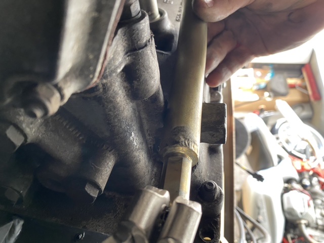
Posted by: Coondog May 10 2020, 04:49 PM
I would call James Patrick on Monday. He had to bend my previously installed PMS bar when i had Bens exhaust setup installed.
Posted by: porschetub May 10 2020, 05:37 PM

So... the engine is in (I’m using the NaroEscape -6 front mount) and, seeming because of the mount, it sits lower than stock. The Patrick Motorsport -6 shift linkage rod I intended on using, wont work. It interferes with the engine case and doesn’t seem to have a workaround. If the engine were 1/4” - 1/2” higher at the firewall, it looks like it would slip in, but alas, the engine is not going anywhere, lol.
I’m tempted to just bend the PMS bar end upward (maybe a couple inches from where it goes from the narrow shank to the bar rod) to give it the clearance but that would change the angle it goes into the rear bushing and connects to the shift lever... so I figured I’d ask if anyone else had an issue with the bar hitting the engine case and any options I might have. I’m OK with modding the old -4 rod too. Might be worth a shot but figured I’d ask here first.
The other threads I found look like the stock rod modded is the move.
Thanks
Rich
You will have to bend it in 2 place otherwise you will get binding @ the gearbox connection,are you tail or side shift? ,my engine was the same being too low,it appeared the repop factory bulkhead mount was welded in the right place but something wasn't right with the engine mount so I cut and rewelded it.
The whole issue if the engine is perfectly positioned in the enginebay its makes it very hard to remove because of the tinware which is hard to remove (in situ) and is in the way.
I don't remember of hand how much I moved it upward but I did found the engine was more horizontal in the opening instead of being nose down if that makes sence,the rear "breast plate tin " fitted better in to the rubber seal also so I knew I was close to correct.
I build a custom shifter set up from the crappy rear rod the PO supplied and ditched the factory alloy coupler,now running 2 uni-joints and a double metal bush console.
Lots of measuring cutting ,adjusting ,machining and pulling it apart many times
 but it works very well....huge improvement.
Good luck.
Posted by: Mark Henry May 11 2020, 05:59 PM
Good job I also built my own shift rod, this is the best set-up for the 914 side shiftier.
Chris at tangerine can hook you up with this shift rod set-up.
http://www.tangerineracing.com/transmission.htm
Rich the rod you have can be modified to work. 


Posted by: roblav1 May 11 2020, 07:59 PM
My conversion side shifter mechanism was a straight shot, no bends. I made it from scratch and used an Apex helicopter joint. Also made my own nylon bushing rear slider in a lathe. Ben's heater boxes were not in the way.
Your mount must be pretty low.
Posted by: Retroracer May 11 2020, 10:04 PM
I purchased the PMS shift rod for my -6 conversion; side shifter and Maddog motor mount. I had a minor clearance issue with it rubbing the engine casing, with the mount welded as per guidance.
I could see from how the engine tin aligned with the apron surround - the rubber seal was not sitting correctly- that the engine was (maybe) 5mm too low in the chassis. It looked as though if I raised the engine slightly then both issues would be helped. I made up some shims to go under the 911 sport mounts from 6mm material; and that did the trick. Not sure if your mount allows the same hack...
So - my advice would be to double check the engine is sitting at approx. the right height, before modifying the linkage?
- Tony
Posted by: sixnotfour May 11 2020, 10:24 PM
Looks like they are needing some dimensional guidance for proper installed height..
unlike the 911 bulkhead style,,[washers] there is no adjust ability
Posted by: sixnotfour May 17 2020, 11:17 AM
:blink:Naro needs to post about this..Most want factory engi.height..Pretty simple info sheet would benefit them and customers...
naro how does the engine tin fit ?
patrick factory height
Attached image(s)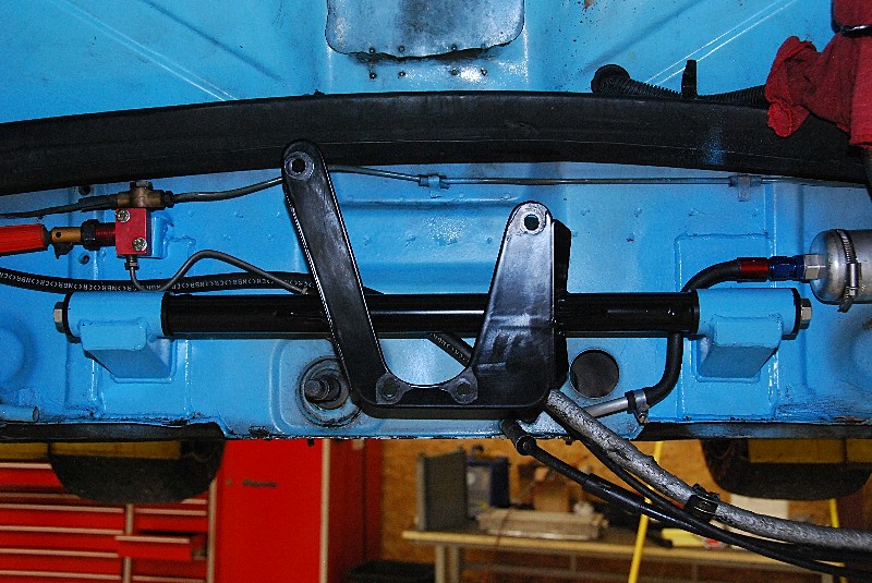
Posted by: RichPugh Sep 20 2020, 06:43 PM
Thanks everyone. Just getting back around to this issue now. Had I known the engine was going to cause shift rod interference sitting as low as it does, I would have asked Translog to weld it in 3/4" higher. I welded it exactly where they say to weld it. It looks exactly like that blue pic above.
The rod only moved back/forth and rotates so I'm not dealing with any side clearance issues with the heat exchanger box... just the bottom of the engine case. I think I can "notch" it where it will go under the case, back up and straight into the side shifter guide without any funky geometry.
-Rich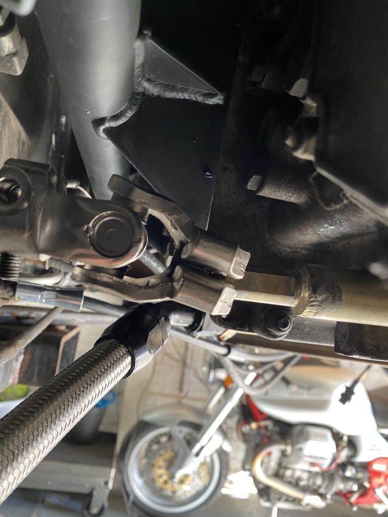
Posted by: RichPugh Sep 20 2020, 06:44 PM
Maybe something like this...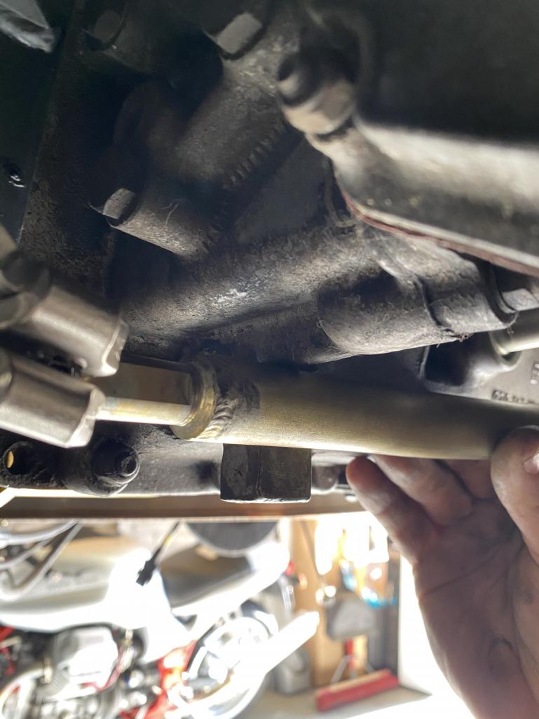
Posted by: mb911 Sep 21 2020, 05:39 AM
I had the same issue with a conversion I did for a customer. I had to cut the bare half way through in 2 spots about 3 inches apart. Then I welded a flat plate in to reinforce. This allowed me to clear the case just enough.
Posted by: JOEPROPER Sep 21 2020, 07:20 AM
I had the same issue with a conversion I did for a customer. I had to cut the bare half way through in 2 spots about 3 inches apart. Then I welded a flat plate in to reinforce. This allowed me to clear the case just enough.
This looks to be a pretty straight forward modification to the rod. @http://www.914world.com/bbs2/index.php?showuser=9892 Is welding the mount 3/4" higher and option or will this cause other interference or geometry problems with the driveline, tin, "levelness" angle etc...???
Posted by: mb911 Sep 21 2020, 07:35 AM
I would highly recommend it .. I personally have now gone to suggestions of using either the Rich Johnson mount or the maddog OEM style to eliminate this issue. The heater valves are also an issue that has to be worked around with the Naro mount.
Posted by: RichPugh Sep 21 2020, 08:13 AM
I would highly recommend it .. I personally have now gone to suggestions of using either the Rich Johnson mount or the maddog OEM style to eliminate this issue. The heater valves are also an issue that has to be worked around with the Naro mount.
Yea... I havent even gotten round to the heat valves
 I'm just hoping I get SOME heat to defrost the windshield. Just worked out some fresh air blower motor gremlins yesterday so fingers crossed, LOL.
Yea I agree... I'd say if Naro made the bottom of their mount plates like 3/4" taller so it lifted the engine up 3/4" but still lined up the same on the firewall ridges, it would be much better. The engine tins would seal correctly, the shift rod clearance wouldnt be an issue, and the only other issues would be with the line to the rear brake valve and whatever I'm not seeing yet with the heater valves. I dont see the benefit of it sitting as low as it does now.

Posted by: PanelBilly Sep 21 2020, 08:47 AM
I’m using my oem rod but rotated it so it clears the engine and Ben’s HEs. I had new holes drilled for the pins on both ends. If you’re going that way be sure to drill them correctly. It’s not just a hole, it bevels back so the pin seats properly. A machine shop will have the right drill to do this. The fox hangs down a bit and I plan to cut it and add a straight section one of these days.
Posted by: live free & drive Sep 21 2020, 09:55 AM
I'm dealing with this same issue right now. I had already welded in the Naro mounts before understanding their issues.
I recently got a hold of a Patrick mount which looks to mount the engine in the proper place according to some measurements taken by another member. The Patrick cross bar can be swapped in, as the spacing is nearly the same. It raises the motor .62" ,which is good, but it also pushes the motor .60" closer to the firewall; which with the Naro mount already being .5" closer puts the engine 1.1" closer to the firewall altogether bringing the axles and trans mounts that much further forward, potentially causing more issues.
I have decided to modify the Naro cross-bar by welding on some machined/threaded offset extensions which will push the bar up .75" hopefully placing everything in proper alignment (although still .5" forward).
Another note is that neither the Naro nor Patrick mounts were anything close to flat at the engine interface- both being out about .125". I was able to "adjust" the Naro mount to flat by percussion persuasion and light lapping, but due to the design the Patrick mount is non adjustable.
There are aspects of each companies engine mount that I think are better than the others solutions, but neither are perfect.
Posted by: mb911 Sep 21 2020, 11:58 AM
I do have a fixture to modify the stock rod if you using stock engine height.. Let me know if anyone needs that mod done..
Posted by: RichPugh Sep 21 2020, 08:42 PM
https://youtu.be/62qQqz_GOT4
Posted by: RichPugh Sep 21 2020, 08:46 PM
I thought it was hitting one of the header pipes but its actually tapping the heat exchanger box so with a little luck adjusting it, it MIGHT clear as is... otherwise, modifying the bar even in the clocked repositioned orientation would probably do the trick. We'll see. I'm gonna snug the set screws down a bit and see how far the side to side action actually moves the bar.
https://www.youtube.com/watch?v=62qQqz_GOT4
Posted by: RichPugh Sep 24 2020, 11:27 AM
Anyone else using a stock -4 bar just clocked/re-indexed? Does it throw off the shifting due to the geometry of the bar end at the gear selector lever at the side?
Posted by: IronHillRestorations Sep 24 2020, 12:05 PM
You can't use a stock 4 side shift bar as is in any way, shape form, or fashion; it's got to be modified. When I was making shift bars I would use an early tail shifter and use those bends. I quit doing them when 3 other guys started making them too. No animas, just not worth it for me.
Basically the bar needs to go about 1/2" down and away from the centerline (looking from the back of the car at the firewall) at about 8 o'clock, then back up the same way at the back. Also the rear that goes into the side shift console isn't straight, it's got a bit of an angle to it. All you've got to do is take off the coupler clamp it in a vise and you'll see the angle at the tail end that you've got to maintain
Posted by: gandalf_025 Sep 24 2020, 12:41 PM
I have a friend that bought the Naro mount and
decided to have it professionally welded in.
He hired a welder out of the Portsmouth Naval Shipyard
to do it. When done, it was too low for the tin to line up
and the shift rod didn’t clear.
Welder builds Submarines, so I found it hard to believe
he installed the parts wrong.
Took some serious modifying to get it to work...
Posted by: RichPugh Sep 24 2020, 01:34 PM
You can't use a stock 4 side shift bar as is in any way, shape form, or fashion; it's got to be modified. When I was making shift bars I would use an early tail shifter and use those bends. I quit doing them when 3 other guys started making them too. No animas, just not worth it for me.
Basically the bar needs to go about 1/2" down and away from the centerline (looking from the back of the car at the firewall) at about 8 o'clock, then back up the same way at the back. Also the rear that goes into the side shift console isn't straight, it's got a bit of an angle to it. All you've got to do is take off the coupler clamp it in a vise and you'll see the angle at the tail end that you've got to maintain
Noted. Yea, the rear section into the side shift guide being "not straight" was my concern. I know the guide allows for some play but its so important for the alignment to be correct that it simply wont shift into all gears correctly if its off/out. I'm gonna play with it a little... There's not much else I have to do to get it driving so I guess a little trial & error with making a shift rod is my new end to 2020, lol.
I have a friend that bought the Naro mount and
decided to have it professionally welded in.
He hired a welder out of the Portsmouth Naval Shipyard
to do it. When done, it was too low for the tin to line up
and the shift rod didn’t clear.
Welder builds Submarines, so I found it hard to believe
he installed the parts wrong.
Took some serious modifying to get it to work...
Yea, I think the consensus is the Naro mount, when welded in as instructed, is simply not right. It sits too low for the engine tin to mate up to the rubber seals and it causes interference with the shift rod. I'm bummed but I'm not taking the engine out to re-weld it 1/2"-3/4" higher. I dunno... maybe I will. I hate that it is so off. Very disappointed.
Posted by: JOEPROPER Sep 24 2020, 02:28 PM
This is disappointing. Maybe the Naro Racing people will chime in here with a solution...
Posted by: mb911 Sep 24 2020, 02:32 PM
You can't use a stock 4 side shift bar as is in any way, shape form, or fashion; it's got to be modified. When I was making shift bars I would use an early tail shifter and use those bends. I quit doing them when 3 other guys started making them too. No animas, just not worth it for me.
Basically the bar needs to go about 1/2" down and away from the centerline (looking from the back of the car at the firewall) at about 8 o'clock, then back up the same way at the back. Also the rear that goes into the side shift console isn't straight, it's got a bit of an angle to it. All you've got to do is take off the coupler clamp it in a vise and you'll see the angle at the tail end that you've got to maintain
Noted. Yea, the rear section into the side shift guide being "not straight" was my concern. I know the guide allows for some play but its so important for the alignment to be correct that it simply wont shift into all gears correctly if its off/out. I'm gonna play with it a little... There's not much else I have to do to get it driving so I guess a little trial & error with making a shift rod is my new end to 2020, lol.
I have a friend that bought the Naro mount and
decided to have it professionally welded in.
He hired a welder out of the Portsmouth Naval Shipyard
to do it. When done, it was too low for the tin to line up
and the shift rod didn’t clear.
Welder builds Submarines, so I found it hard to believe
he installed the parts wrong.
Took some serious modifying to get it to work...
Yea, I think the consensus is the Naro mount, when welded in as instructed, is simply not right. It sits too low for the engine tin to mate up to the rubber seals and it causes interference with the shift rod. I'm bummed but I'm not taking the engine out to re-weld it 1/2"-3/4" higher. I dunno... maybe I will. I hate that it is so off. Very disappointed.
Yup I did the same thing.. Thats why I can no longer recommend the mount for street cars.. Race cars sure no problem but street car with heat, engine tins that should seal are a no go..
Again I do have a fixture to make this work out of a 4cyl side shift rod if anyone needs one done let me know.
Posted by: live free & drive Sep 24 2020, 04:43 PM
I don't know if you all have seen these posts comparing the Naro and Patrick mounts side by side, but it's in this thread:
http://www.914world.com/bbs2/index.php?showtopic=346616&hl=PATRICK++MOUNT
It would be nice if Naro offered a stock location crossbar moving the engine up 3/4" and rearward 1/2". It would not be too hard to jig up for that.
Posted by: nditiz1 Sep 24 2020, 06:18 PM
@http://www.914world.com/bbs2/index.php?showuser=18068 I have a modified shift shaft that Ben did for my build. It has a slight bend and will be used with the oem style mount. You are more than welcome to try it out since I'm not close to that part in my build. Just let me know, I'm probably about a 30 - 40min drive for you.
Posted by: RichPugh Sep 24 2020, 08:43 PM
@http://www.914world.com/bbs2/index.php?showuser=18068 I have a modified shift shaft that Ben did for my build. It has a slight bend and will be used with the oem style mount. You are more than welcome to try it out since I'm not close to that part in my build. Just let me know, I'm probably about a 30 - 40min drive for you.
Thanks! Will totally try it out! I'll be there in 45 minutes! LOL.
You avail this weekend?
Posted by: RichPugh Sep 24 2020, 08:50 PM
I don't know if you all have seen these posts comparing the Naro and Patrick mounts side by side, but it's in this thread:
http://www.914world.com/bbs2/index.php?showtopic=346616&hl=PATRICK++MOUNT
It would be nice if Naro offered a stock location crossbar moving the engine up 3/4" and rearward 1/2". It would not be too hard to jig up for that.
Skimmed thru... Yea, that would be nice. A new engine side portion of the mount wouldnt be too terribly hard to fab up or modify. Something that can allow the mounts to stay where they are but position the engine up 3/4" and further towards the rear about 1/4-1/2"... Maybe thats the move. I'm gonna get it moving under its own power first but perhaps I should start modding the engine side cradle and bar to actually position the engine more close to stock.
I'm not terribly mad at Naro. They didnt sell the product as anything other than a race mount and clearly said it positioned the engine lower. I just didnt know it was going to cause shift linkage interference.
Posted by: JmuRiz Sep 24 2020, 09:39 PM
I’m sure I’ll send my /4 rod to Ben....maybe in a box with an old one of his (at least I think so) sport muffler to rally muffler modify
Posted by: nditiz1 Sep 24 2020, 09:42 PM
I will be around all weekend. Shoot me a PM with your contact info.
Posted by: mb911 Sep 25 2020, 04:28 AM
Rich and Nick the only issue with using that linkage I moded is it was not modded for a naro mount
Posted by: nditiz1 Sep 25 2020, 06:11 AM
Understood Ben. So do you have two jigs, one for the Naro scape setup and one for the OEM style?
Posted by: mb911 Sep 25 2020, 07:26 AM
Understood Ben. So do you have two jigs, one for the Naro scape setup and one for the OEM style?
For a naro mount I would have create a cut out to clear the chain case on the engine otherwise the same fixture.
Posted by: Tdskip Sep 25 2020, 09:02 AM
Oh boy - I was planning on welding in the Naro Mount on my /6 today. This is giving me pause...
Posted by: mb911 Sep 25 2020, 09:15 AM
Oh boy - I was planning on welding in the Naro Mount on my /6 today. This is giving me pause...
If you do just weld it 3/4" higher then it says. Also note I found that it pulls the trans mounts forward about 7 degrees which translates to the mount being to short aft in my mind.
Posted by: Mark Henry Sep 25 2020, 10:09 AM
I made my own RJ copy mount*, I mounted the bulkhead mount to the motor, then I raised the engine and trans into position and bolted up the rear trans mounts. I got the engine raised up to where I wanted it to sit and I tack welded the mount in place. I put in enough tack welds to hold the weight of the engine, took out the jack and confirmed that it was sitting correct with full weight.
In lining up my home made bulkhead mount I found several areas I had to mod and/or clearance before I tacked it in. I got it right first time but I could have easily cut out the tack welds and reposition it if needed.
Only when I was totally happy and tacked in did I remove the engine/trans and fully weld in the mount.
* Special thanks to @http://www.914world.com/bbs2/index.php?showuser=8858 at RD for laser cutting the parts for the mount.
Posted by: mb911 Sep 25 2020, 10:14 AM
I made my own RJ copy mount, I mounted the bulkhead mount to the motor, then I raised the engine and trans into position and bolted up the rear trans mounts. I got the engine raised up to where I wanted it to sit and I tack welded the mount in place. I put in enough tack welds to hold the weight of the engine, took out the jack and confirmed that it was sitting correct with full weight.
In lining up my home made bulkhead mount I found several areas I had to mod and/or clearance before I tacked it in. I got it right first time but I could have easily cut out the tack welds and reposition it if needed.
Only when I was totally happy and tacked in did I remove the engine/trans and fully weld in the mount.
That is what I did with my 1st conversion.. This time I made a factory copy and used the mad dog engine side and used factory measurements.. Was spot on and works perfectly.
Posted by: Mark Henry Sep 25 2020, 10:21 AM
That is what I did with my 1st conversion.. This time I made a factory copy and used the mad dog engine side and used factory measurements.. Was spot on and works perfectly.
Not mounting the bar to the engine and then mounting the engine with transmission and bolting up the rear mounts is the OP's big mistake.
This step must be done every time...I don't give a flying fuchs who made the mount.
Posted by: nditiz1 Sep 25 2020, 12:16 PM
@http://www.914world.com/bbs2/index.php?showuser=21666 try to return the naroscape if you can and go with the mad dog oem. Its a little more, think I padis ~400 for the mount and bushing, but it will be worth it having everything sit where it is supposed to.
Posted by: JOEPROPER Sep 25 2020, 01:01 PM
@http://www.914world.com/bbs2/index.php?showuser=21666 try to return the naroscape if you can and go with the mad dog oem. Its a little more, think I padis ~400 for the mount and bushing, but it will be worth it having everything sit where it is supposed to.
Sounds like there are going to be mods either way. I'm going to mount my Naro Escape mount 3/4" higher with engine and trans installed to make sure installed height and angles are correct. This will be my first conversion on a 914 and like everyone else, will deal with whatever modifications need to be made.
Posted by: RichPugh Sep 25 2020, 06:15 PM
Oh boy - I was planning on welding in the Naro Mount on my /6 today. This is giving me pause...
If you do just weld it 3/4" higher then it says. Also note I found that it pulls the trans mounts forward about 7 degrees which translates to the mount being to short aft in my mind.
This >>> 100%. Maybe even higher up... the front rubber seal would slip under the -6 engine tins if it were up almost an inch. It absolutely pulls it forward too as my trans mounts are at the very limit of what I would consider safe, lol. It pulls the engine closer to the firewall which may translate into being off for the shifter too...
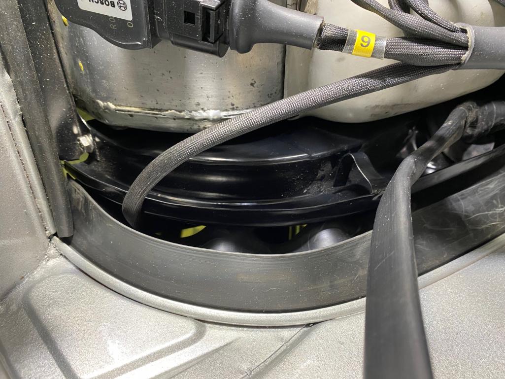
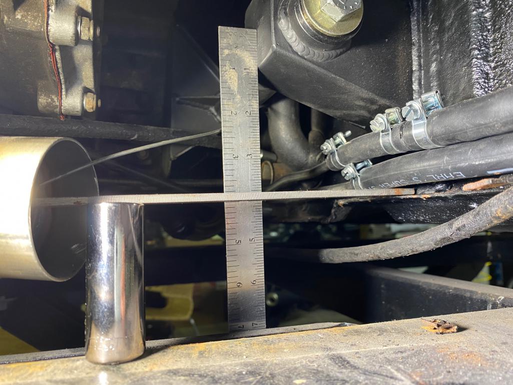
Here's the gap I'm left with at the front and rear rubber seals using the Naro mount installed as instructed. Like I said and others have suggested, if youre going to use it and want the engine to fit closer to how the stock 6 would fit, welt the mounts UP 3/4"-1" on the firewall from off the bottom ridge.
Posted by: RichPugh Sep 25 2020, 06:32 PM
This step must be done every time...I don't give a flying fuchs who made the mount.
Lesson learned. Listening to the manufacturers installation rules/guidelines/instructions was my mistake. It simply DOES NOT position the engine in a good place (for my goals, at least)... so... I can do what you suggested, re-welding the mounts to the firewall in a higher, more ideal position but it doesnt fix the situation with the engine being about 1/2" too far forward closer to the firewall. The firewall kinda pitches backwards slightly so it might move it back marginally.
I will either:
1. Drop the engine, re-engineer the crossbar/cradle portion of the Naro mount to position the engine UP 3/4" and further rearward about 1/2"... Decent work but massive improvement.
2. Re-weld the firewall mounts up 3/4" UP and deal with the forward positioning... not ideal but better.
3. Leave it just as it is and just mod a shift rod bar to work... probably what I'll do in the interim.
Posted by: RichPugh Sep 25 2020, 06:33 PM

Posted by: RichPugh Sep 25 2020, 06:39 PM
Rich and Nick the only issue with using that linkage I moded is it was not modded for a naro mount
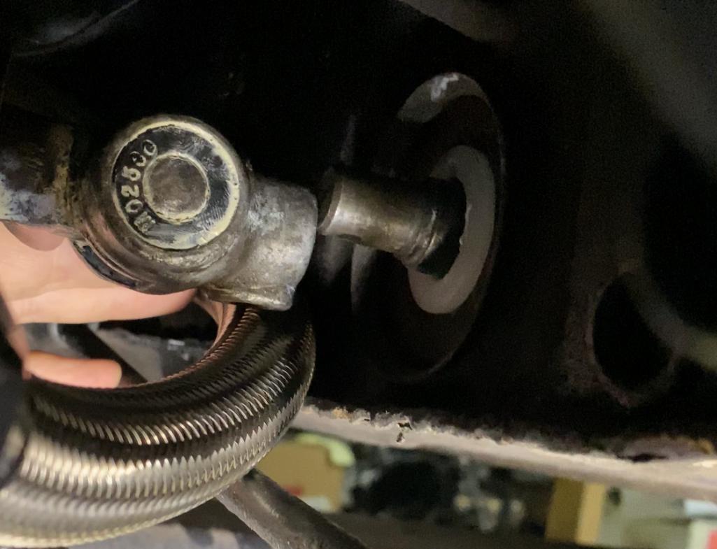
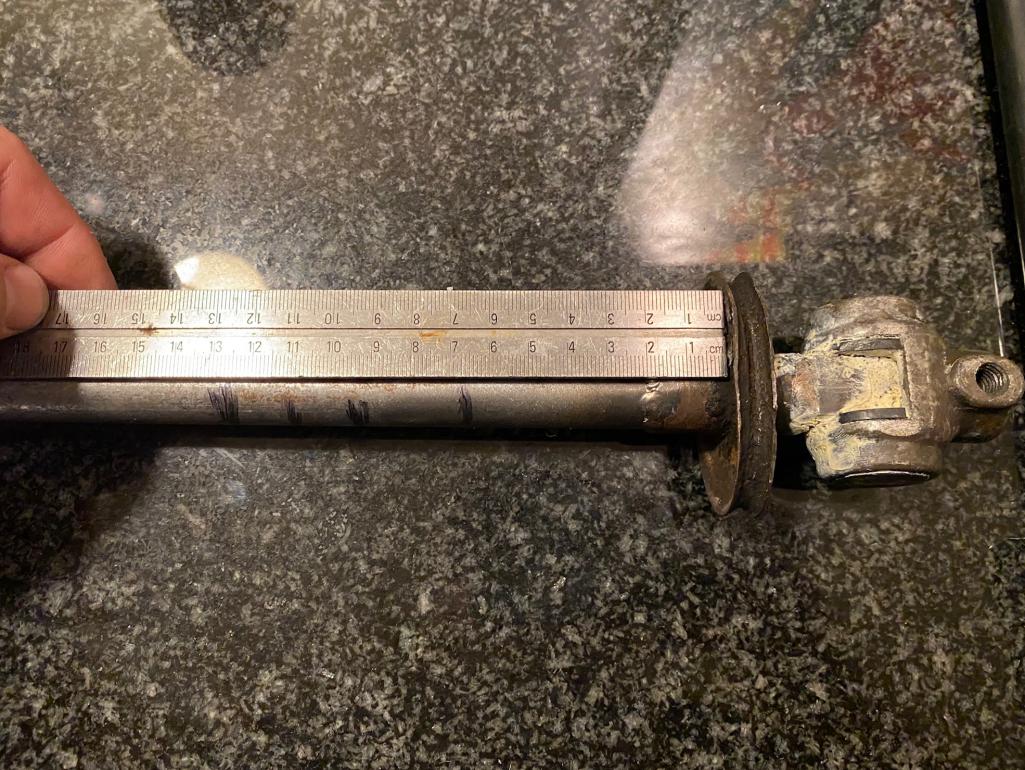
I test fit it to see how far off it was and made a few marks to denote the extreme limits of the shift rod position when shifting forward/rearward.
The 2 center-most marks on the bar denotes the area where the case touches the bar in neutral (if the bar were connected). The forward most and rear most marks denote the furthest place the case would contact the bar when shifting forward and backward.
Looks like your bar would be perfect if it were notched at about 60mm from the rubber boot lip, to drop down, go straight back until about 135mm then go back up and continue straight back.
Ignore the dripping CV axle flanges... LOL. I havent cleaned them, re-greased them and replaces the gaskets yet.
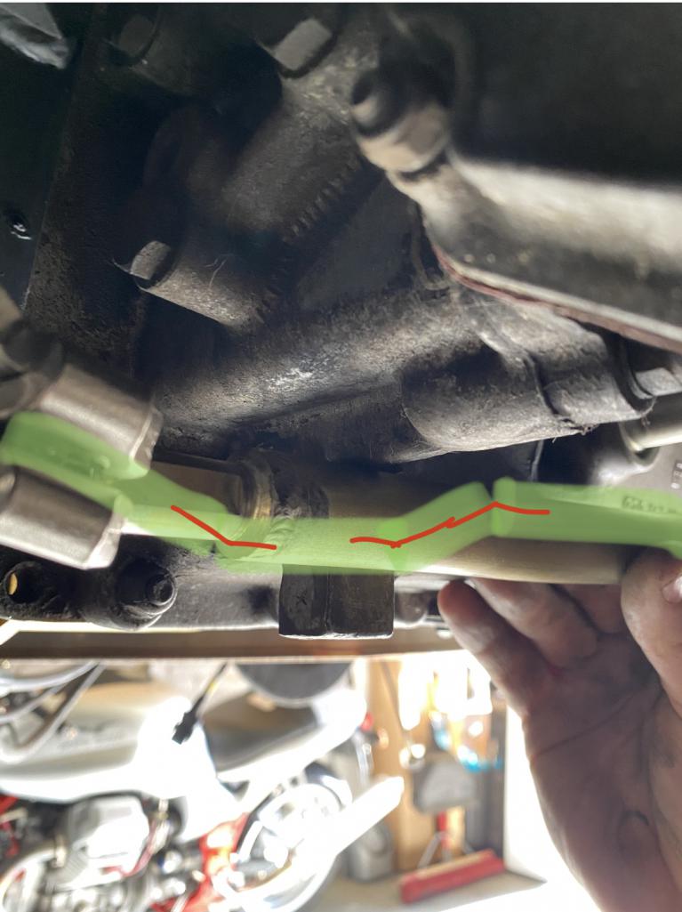
Posted by: RichPugh Sep 25 2020, 07:41 PM
So... Something like this would work. Ignore the rudimentary drawing and orientation of the bar. Pretend its correctly oriented horizontally and this would drop down...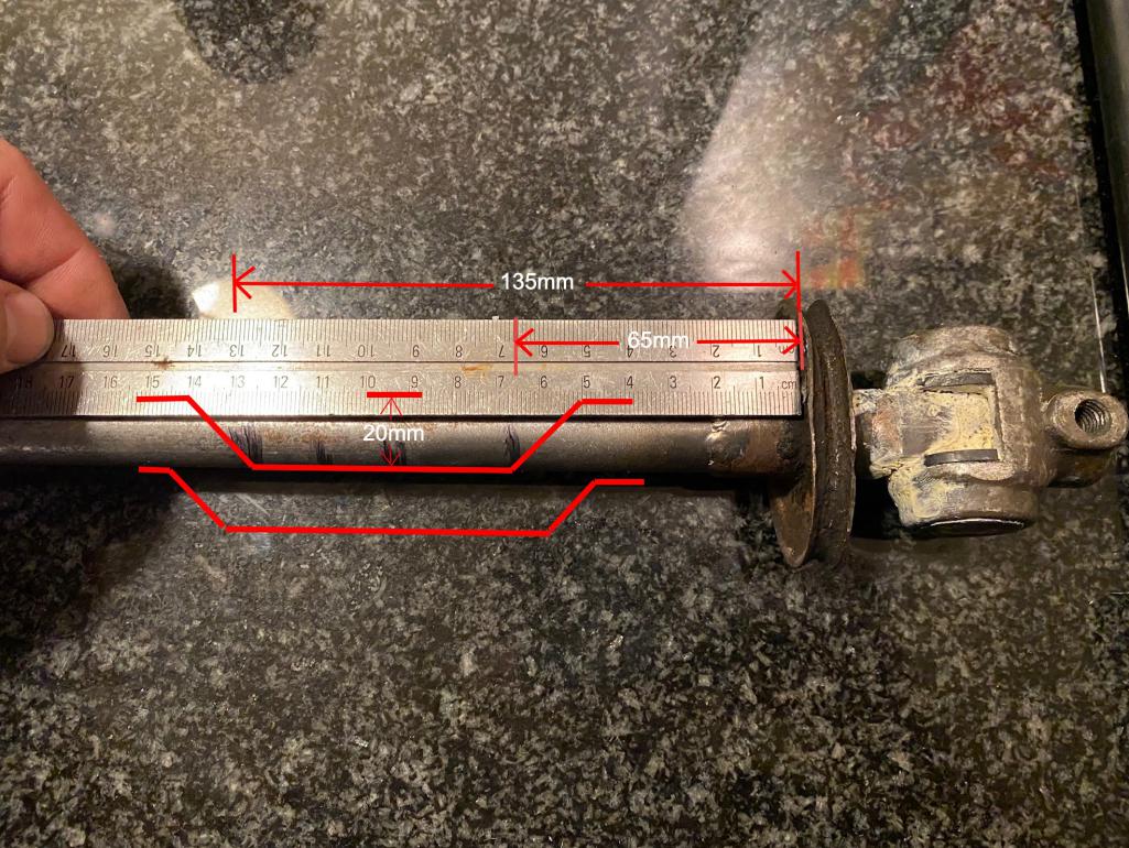
Posted by: RichPugh Sep 28 2020, 03:45 PM
Rich and Nick the only issue with using that linkage I moded is it was not modded for a naro mount
Hey Ben, think you could make another bar like the one you made that I borrowed from Nick, but put a nice big notch in it to easily clear my -6 case? Pic posted above is the general parameters that would work.
Posted by: gandalf_025 Sep 28 2020, 04:05 PM
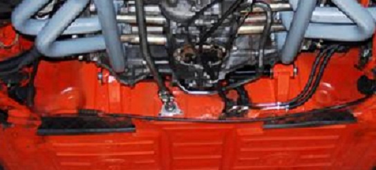
This is what they did to the 914-6 race cars
back in the day to clear a tab on the early aluminum
911 cases..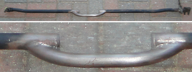
Posted by: mb911 Sep 28 2020, 04:10 PM
Rich and Nick the only issue with using that linkage I moded is it was not modded for a naro mount
Hey Ben, think you could make another bar like the one you made that I borrowed from Nick, but put a nice big notch in it to easily clear my -6 case? Pic posted above is the general parameters that would work.
Yes for sure.. Let me know.. Also note if you send it please send to my new address.
Posted by: mb911 Sep 28 2020, 06:56 PM
http://www.914world.com/bbs2/index.php?showtopic=339906&st=40
Please see the last page. A bit of info
Posted by: RichPugh Sep 28 2020, 07:52 PM
http://www.914world.com/bbs2/index.php?showtopic=339906&st=40
Please see the last page. A bit of info
Thanks, man. I shot Bob an email. That thread showing the position differences between the Naro and PMS mount is quite enlightening. I wish I would have simply gotten the PMS mount... I was trying to support the Naro guys.
Posted by: RichPugh Sep 28 2020, 07:56 PM
This is what they did to the 914-6 race cars
back in the day to clear a tab on the early aluminum
911 cases..
This "notch", placed close to the shift rod knuckle, would def clear the case. It wouldnt help with the other issue being the forward position of the engine and trans, but would def clear the case.
Posted by: Tdskip Sep 28 2020, 10:10 PM
Great discussion.
Sounds like the Naro mount needs some additional thickness to either where it welds to the firewall or where it attaches to the engine.
Won't being 1/2 inch too far forward put a lot of stress on the transmission ears?
Posted by: RichPugh Sep 29 2020, 10:10 AM
Great discussion.
Sounds like the Naro mount needs some additional thickness to either where it welds to the firewall or where it attaches to the engine.
Won't being 1/2 inch too far forward put a lot of stress on the transmission ears?
Thats another concern I have with where the lump is placed. It's definitely not sitting in the trans mounts squarely. I dont think the solution is adding "thickness" to the welded portions of the Naro mount... MAYBE modifying the mount position for the bar at the end of the welded mount "ears" could be a fix for them moving forward. In my case, I think the cradle section that mounts to the engine can/needs to be modified (basically reengineered) to correct it, lifting the engine upwards every bit of 3/4" and rearward about 1/2". The mounts on the firewall are positioned in a way that it currently allow room for the rear brake bias assembly to simply be moved upwards and still fit (tightly) under the engine tin shelf. If we were to reposition them further upwards, that would have to be completely relocated. The welded ears can stay... the cradle that mounts to the engine should be addressed, in my case... probably, LOL.
Posted by: mb911 Sep 29 2020, 10:15 AM
Great discussion.
Sounds like the Naro mount needs some additional thickness to either where it welds to the firewall or where it attaches to the engine.
Won't being 1/2 inch too far forward put a lot of stress on the transmission ears?
Thats another concern I have with where the lump is placed. It's definitely not sitting in the trans mounts squarely. I dont think the solution is adding "thickness" to the welded portions of the Naro mount... MAYBE modifying the mount position for the bar at the end of the welded mount "ears" could be a fix for them moving forward. In my case, I think the cradle section that mounts to the engine can/needs to be modified (basically reengineered) to correct it, lifting the engine upwards every bit of 3/4" and rearward about 1/2". The mounts on the firewall are positioned in a way that it currently allow room for the rear brake bias assembly to simply be moved upwards and still fit (tightly) under the engine tin shelf. If we were to reposition them further upwards, that would have to be completely relocated. The welded ears can stay... the cradle that mounts to the engine should be addressed, in my case... probably, LOL.
That is a great point and easily modded.
Posted by: RichPugh Sep 29 2020, 12:24 PM
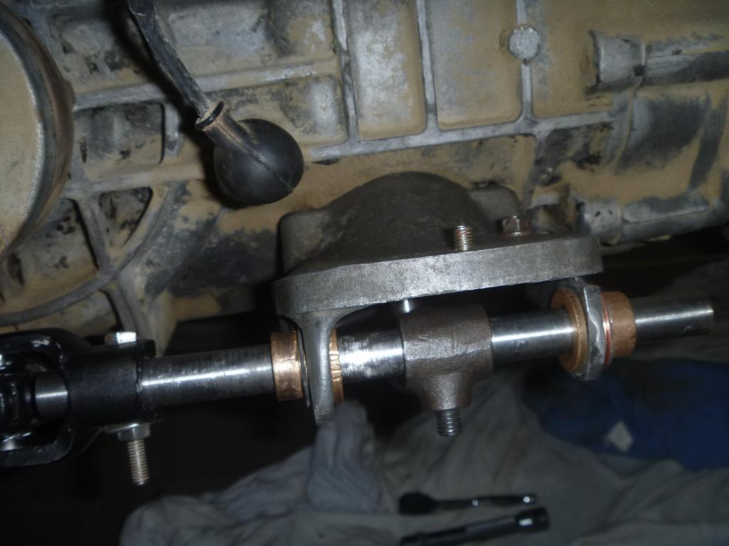
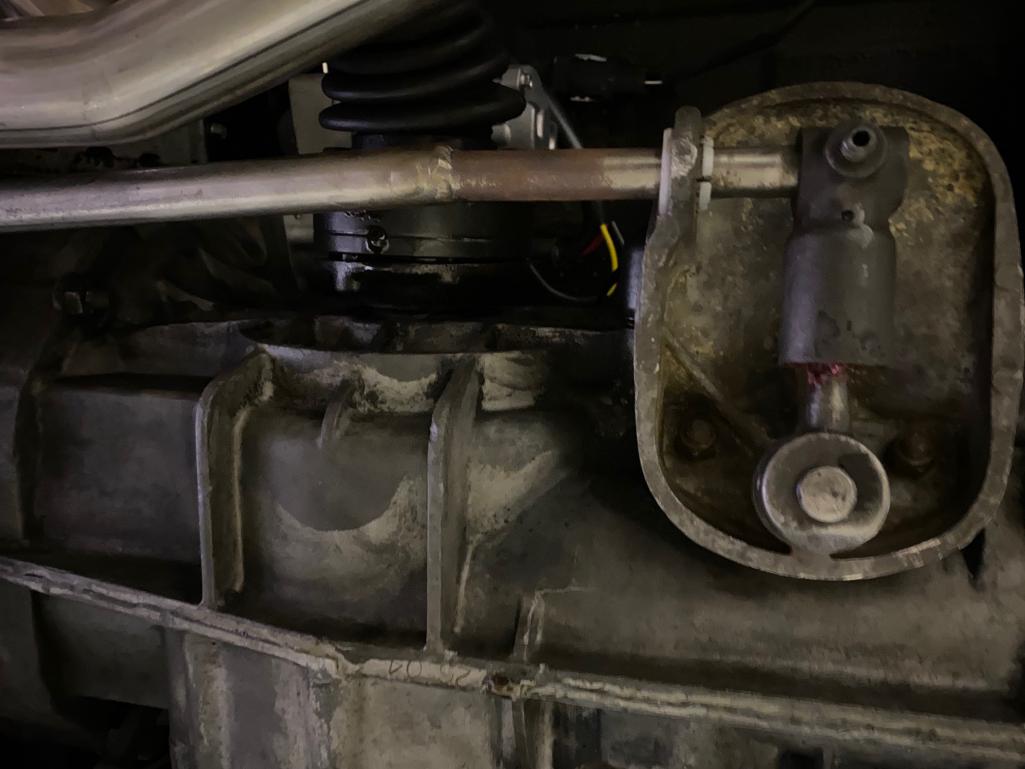
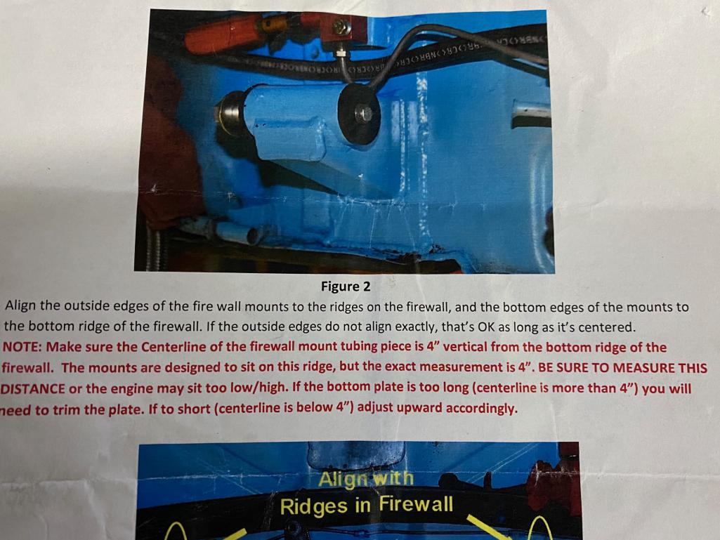
Here's just a couple pics showing exactly where the mount ears were welded into place as well as thee Naro instructions. they are exactly where Naro tells you to put them. They're exactly 4" from the bottom ridge of the firewall to the center of the cross bar. please excuse my rudimentary bottom level line made up of a file and a socket, lol.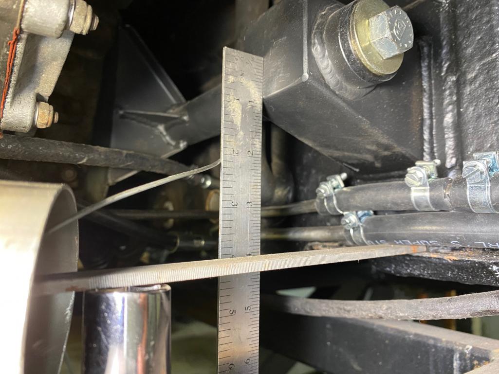
Posted by: RichPugh Sep 29 2020, 12:52 PM
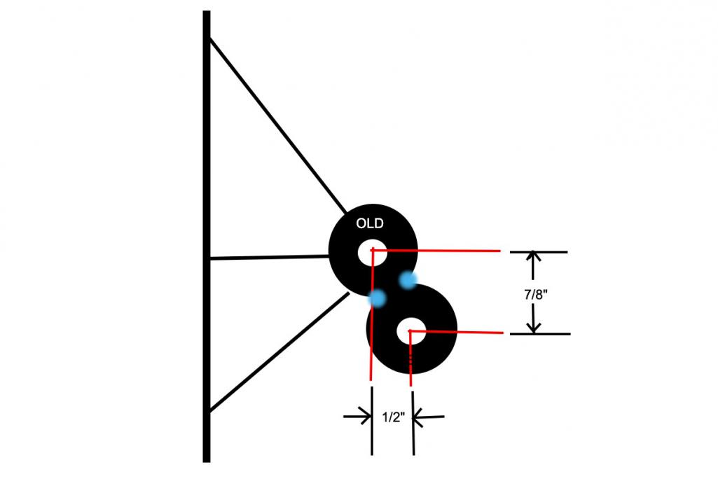
I was considering adding a new 2nd "bar" to the existing mount. One that would lift the engine up 7/8" and position it back 1/2". Something like this (excuse the remedial sketch). The blue just signifies welds all the way down the bar.
The other option would be to cut off the face mounting plate that connects to the engine case, cut a new one that lifts the engine up 7/8", wre-weld it into place and then space it off the case w/ 1/2" spacers/nuts/washers... something. Ughhh
Posted by: Tdskip Sep 30 2020, 06:17 AM
Why couldn’t we “just” do this?
Add thickness to the mount and relocate the u-shaped piece that boots to the engine up and back? Excuse pre-second cup of coffee drawing but you get the idea.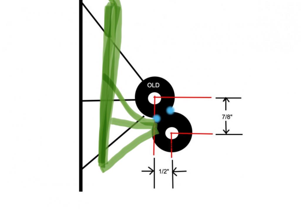
Posted by: Tdskip Sep 30 2020, 06:21 AM
One other way to go it is to add spacers on the mount (provided they are very strong), like the green shown here on the u-shaped piece.
This is how Lotus did it on the Elan which, granted, only has a 1.6L engine.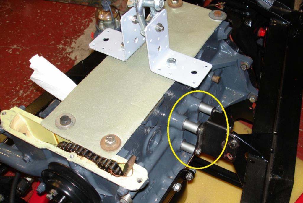
Posted by: RichPugh Sep 30 2020, 09:54 AM
One other way to go it is to add spacers on the mount (provided they are very strong), like the green shown here on the u-shaped piece.
This is what I mentioned above too... just using spacers for the fore/aft adjustment and figuring our another way to "lift" the engine up. Maybe Bob @ Naro will help. We have (at least) 2 identical situations... 'Live Free & Drive' is having identical issues. Maybe Naro made a bad batch?
Posted by: Tdskip Sep 30 2020, 10:24 AM
One other way to go it is to add spacers on the mount (provided they are very strong), like the green shown here on the u-shaped piece.
This is what I mentioned above too... just using spacers for the fore/aft adjustment and figuring our another way to "lift" the engine up. Maybe Bob @ Naro will help. We have (at least) 2 identical situations... 'Live Free & Drive' is having identical issues. Maybe Naro made a bad batch?
So, in theory, if you welded the existing mount 3/4 higher than instructions and then added 1/2 spacer we should be OK?
Posted by: mb911 Sep 30 2020, 10:45 AM
One other way to go it is to add spacers on the mount (provided they are very strong), like the green shown here on the u-shaped piece.
This is what I mentioned above too... just using spacers for the fore/aft adjustment and figuring our another way to "lift" the engine up. Maybe Bob @ Naro will help. We have (at least) 2 identical situations... 'Live Free & Drive' is having identical issues. Maybe Naro made a bad batch?
So, in theory, if you welded the existing mount 3/4 higher than instructions and then added 1/2 spacer we should be OK?
Yes that is what I figured as well.
Posted by: Mark Henry Sep 30 2020, 10:55 AM
I mounted the bulkhead mount to the motor, then I raised the engine and trans into position and bolted up the rear trans mounts. I got the engine raised up to where I wanted it to sit and I tack welded the mount in place. I put in enough tack welds to hold the weight of the engine, took out the jack and confirmed that it was sitting correct with full weight.
In lining up my home made bulkhead mount I found several areas I had to mod and/or clearance before I tacked it in. I got it right first time but I could have easily cut out the tack welds and reposition it if needed.
Only when I was totally happy and tacked in did I remove the engine/trans and fully weld in the mount.
-Bolt the mount and the transmission to the engine.
-Put it in the car and bolt up the rear transmission (to body) mount bolts.
-Use your jack to get the correct height of the front.
-install the seal, hook it on under the engine tin edge, get it perfect before you weld.
-Weld the tacks in an easy to grind out area in case you make a mistake.
-Tack it well enough to hold the weight and check.
-Check your seal, not too tight... not too loose, it should hook on the engine tin perfectly.
-Remove engine/transmission and finish welding.
Doing it this way my seal hooks perfectly onto the tin. Except for finding center I used no measuring tools for the job, I let the trans mounts do that job. I'd say my engine placement is as perfect as you can get.
My shift rod is straight but it only clears by 1/4" and I have a Tangirine shifter console mod.
Posted by: RichPugh Sep 30 2020, 11:09 AM
Welding the ears in 3/4" higher would/could result in interference complication with the rear brake bias unit (that can currently just move upward slightly and remain connected as is). I was going to leave my 'ears' in place on the firewall and re-engineer the cradle portion of the mount... the U-shaped plate that mounts to the engine case, if it was cut off and either re-welded in a 3/4" higher position, or re-cut and drilled higher and welded in new... Not sure. It's a lot to deal with. I didnt want to pull the engine back out so... I guess I'm going to have to at this point.
Posted by: RichPugh Sep 30 2020, 11:13 AM
-Put it in the car and bolt up the rear transmission (to body) mount bolts.
-Use your jack to get the correct height of the front.
-install the seal, hook it on under the engine tin edge, get it perfect before you weld.
-Weld the tacks in an easy to grind out area in case you make a mistake.
-Tack it well enough to hold the weight and check.
-Check your seal, not too tight... not too loose, it should hook on the engine tin perfectly.
-Remove engine/transmission and finish welding.
Doing it this way my seal hooks perfectly onto the tin. Except for finding center I used no measuring tools for the job, I let the trans mounts do that job. I'd say my engine placement is as perfect as you can get.
My shift rod is straight but it only clears by 1/4" and I have a Tangirine shifter console mod.
Did you have to relocate the rear brake bias unit? How high off the firewall bottom ledge is the centerline of the bolt holes in your ears? How long ago did you do this? This was my initial thought process too but like a good boy, I followed the instructions
Lesson learned... but my ears are already welded. I know for a fact I could not have had them welded any higher without removing and relocating the rear brake bias unit.
Posted by: JOEPROPER Sep 30 2020, 11:22 AM
Maybe you could weld to the front of the U shaped bracket, a piece and drill holes to mount to the front of the engine. This would put the engine / trans assembly back a little further in addition to raising the engine in the engine bay... 2 pieces of channel may work for that with a little work to make it look okay...
Posted by: Mark Henry Sep 30 2020, 11:29 AM
-Put it in the car and bolt up the rear transmission (to body) mount bolts.
-Use your jack to get the correct height of the front.
-install the seal, hook it on under the engine tin edge, get it perfect before you weld.
-Weld the tacks in an easy to grind out area in case you make a mistake.
-Tack it well enough to hold the weight and check.
-Check your seal, not too tight... not too loose, it should hook on the engine tin perfectly.
-Remove engine/transmission and finish welding.
Doing it this way my seal hooks perfectly onto the tin. Except for finding center I used no measuring tools for the job, I let the trans mounts do that job. I'd say my engine placement is as perfect as you can get.
My shift rod is straight but it only clears by 1/4" and I have a Tangirine shifter console mod.
Did you have to relocate the rear brake bias unit? How high off the firewall bottom ledge is the centerline of the bolt holes in your ears? How long ago did you do this? This was my initial thought process too but like a good boy, I followed the instructions
Lesson learned... but my ears are already welded. I know for a fact I could not have had them welded any higher without removing and relocating the rear brake bias unit.
I actually cut out, modified and welded in a couple of gussets in the brake bias area. I had to clearance a few out other areas, one to clear the shiftrod boot.
But note mine was an RJ mount copy that was copied by someone unknown to me, I scavanged in parts from a 911 mount and the plans had a few mistakes as well.
Posted by: ClayPerrine Sep 30 2020, 11:51 AM
Unfortunately, all of our parts are not produced by highly trained Porsche factory engineers with lots of experience and lots of testing.
Bob's mounts, like the Rich Johnson mount are made by talented enthusiasts with lots of time and limited money. They don't really get the same level of testing factory parts do. So you are likely to have issues like this one. Plus, after almost 50 years, these cars have been customized so much that no two cars are alike.
So we build this stuff, and hope everyone understands that it will require tweaking for your use case.
I have been friends with Rich Johnson since the middle 90s. He makes great parts, and I have one of his conversion mounts in the 4.0L car. When I converted it from a 2.4 to the 4.0 engine, I had to buy a different mount because the half that fits on the 2.4 won't fit on to a 3.6 engine case. We built a jig on a 901 trans, and made the transmission mounts for the Cayman trans fit the jig.
We put the engine and trans in the car, and the trans mounts were almost 2 inches to the rear. I thought the jig was wrong, but when I pulled the engine/trans back out, I found the 3.6 engine mount was about 2 inches thicker than the 2.4 engine mount. This was done to clear the pulleys on the 3.6. It made the engine tin too short on the front too. Because I have a clewett serpentine belt setup on this engine, I shortened the plate in the front mount to the same height as the 2.4 mount. Then everything fit correctly.
That is an example of "You may have to tweak it to get it to fit your application right."
Posted by: Steve Sep 30 2020, 11:53 AM
-Put it in the car and bolt up the rear transmission (to body) mount bolts.
-Use your jack to get the correct height of the front.
-install the seal, hook it on under the engine tin edge, get it perfect before you weld.
-Weld the tacks in an easy to grind out area in case you make a mistake.
-Tack it well enough to hold the weight and check.
-Check your seal, not too tight... not too loose, it should hook on the engine tin perfectly.
-Remove engine/transmission and finish welding.
Doing it this way my seal hooks perfectly onto the tin. Except for finding center I used no measuring tools for the job, I let the trans mounts do that job. I'd say my engine placement is as perfect as you can get.
My shift rod is straight but it only clears by 1/4" and I have a Tangirine shifter console mod.
Did you have to relocate the rear brake bias unit? How high off the firewall bottom ledge is the centerline of the bolt holes in your ears? How long ago did you do this? This was my initial thought process too but like a good boy, I followed the instructions
Lesson learned... but my ears are already welded. I know for a fact I could not have had them welded any higher without removing and relocating the rear brake bias unit.
I actually cut out, modified and welded in a couple of gussets in the brake bias area. I had to clearance a few out other areas, one to clear the shiftrod boot.
But note mine was an RJ mount copy that was copied by someone unknown to me, I scavanged in parts from a 911 mount and the plans had a few mistakes as well.
AFAIK vellios (rip) designed the mount first and then Rich Johnson copied it. I have the Rich Johnson mount. Couldn’t be happier with it. Tilting the engine with the Other mount makes no sense if you have heat exchangers, etc in the way.
I also have no shift rod or engine height issues. My shift rod is a straight rod with no bends. Worked fine with the previous 2.7 and now 3.2 power plant.
Posted by: Mark Henry Sep 30 2020, 12:35 PM
AFAIK vellios (rip) designed the mount first and then Rich Johnson copied it. I have the Rich Johnson mount. Couldn’t be happier with it.
For all I know my mount could have been copied from a Vellios.
To do a /6 you either need deep pockets or you have to be handy.

These days maybe a bit of both.

Posted by: RichPugh Sep 30 2020, 01:37 PM
Maybe you could weld to the front of the U shaped bracket, a piece and drill holes to mount to the front of the engine. This would put the engine / trans assembly back a little further in addition to raising the engine in the engine bay... 2 pieces of channel may work for that with a little work to make it look okay...
This is actually a good idea. Instead of cutting the original u-shaped mounting plate off, just cut a new plate, weld it to the existing plate, drill new holes in it and thru the old plate for the correct height position and space it off the engine a bit more to make the fore/aft adjustment needed to push it rearward.
This seems much less daunting than re-engineering the bar or the whole cradle portion or re-welding the ears up higher creating more problems.
Posted by: Tdskip Oct 1 2020, 12:31 PM
Like this - with the red being thicker steel to help located it back toward the rear of the car?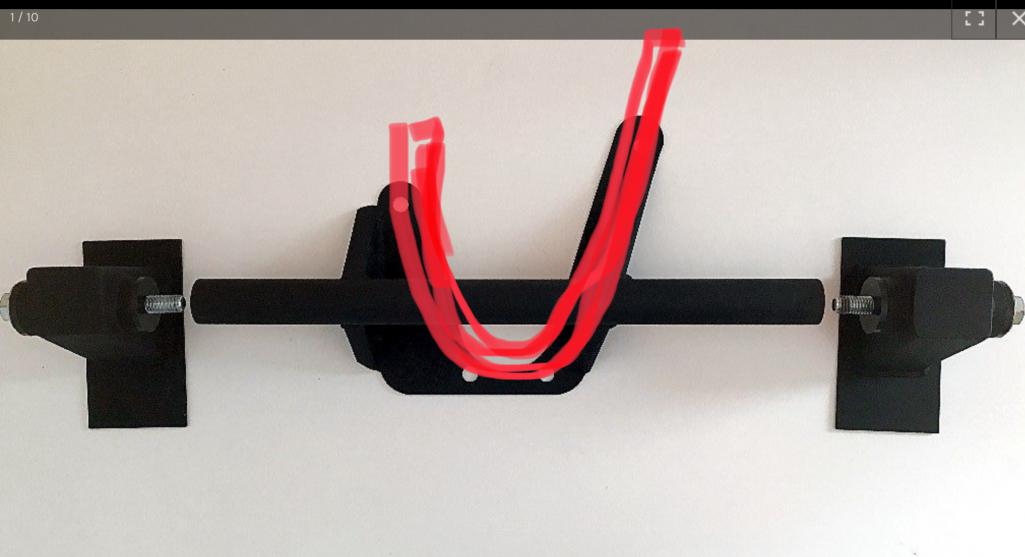
Posted by: mb911 Oct 1 2020, 06:19 PM
Like this - with the red being thicker steel to help located it back toward the rear of the car?
Personally I would just make the mounting flange thicker.
Posted by: porschetub Oct 2 2020, 05:30 PM
This step must be done every time...I don't give a flying fuchs who made the mount.
Lesson learned. Listening to the manufacturers installation rules/guidelines/instructions was my mistake. It simply DOES NOT position the engine in a good place (for my goals, at least)... so... I can do what you suggested, re-welding the mounts to the firewall in a higher, more ideal position but it doesnt fix the situation with the engine being about 1/2" too far forward closer to the firewall. The firewall kinda pitches backwards slightly so it might move it back marginally.
I will either:
1. Drop the engine, re-engineer the crossbar/cradle portion of the Naro mount to position the engine UP 3/4" and further rearward about 1/2"... Decent work but massive improvement.
2. Re-weld the firewall mounts up 3/4" UP and deal with the forward positioning... not ideal but better.
3. Leave it just as it is and just mod a shift rod bar to work... probably what I'll do in the interim.
Sorry to see you have this situation,not uncommon to see an engine too low,mine was by 15mm so because it was a copy of an original "6" setup I was able to modify the mount on the case by moving the centre bolt tube that runs the bolt to the rubber mount.
The fact that your engine is also too far fwd is strange and tells me there is some issue with the design...seems odd the member/vendor hasn't chimed in
 .
.I would expect your trans bolts will be somewhat out of square with the fwd position you have now ??.
Options you provided ;
1. yes and IMO the best but not easiest solution as you will have to re:engineer the centre bar by cutting it and using flat bar steel to create required offset up and fwd,you will need to jig it up to get this right.
2. I can't see how you would manage to cut/relieve the welds on the b/head and then you still have the issue of alignment for and aft.
3. you could but you may find its more of a bandage and may later on make you wish you had taken option #1.
From what I have seen you don't want the engine tin a tight fit on the sealing rudders otherwise installation of the engine can be rather hard ,after I moved my engine up I found removing the side tin was the only way the engine go up fully otherwise you start bending the tin,but it is still in a better position height wise or atleast in my case.
Maybe a mod on the case mount could be the only solution but don't really know,good luck sorting
 .
.Posted by: sixnotfour Oct 2 2020, 09:09 PM
here is the numbers to help
http://www.914world.com/bbs2/index.php?showtopic=346616&hl=
Posted by: Tdskip Oct 3 2020, 08:51 AM
here is the numbers to help
http://www.914world.com/bbs2/index.php?showtopic=346616&hl=
Very helpful, thank you.
I woke up dreaming about this last night, sad but true, so I should probably figure out an approach and just be done with it.
I am leaning towards mounting the Naro Mount as instructed on the firewall, thereby not having to deal with the rear brake stuff, but extending the engine mount up by adding in additional steel plate.
The thickness of the additional steel plate will move the engine back away from the firewall and I should be able to readily raise the bolt holes by the 3/4 of an inch necessary.
@md911 I think that’s what you suggested, and it seems like a viable option I’ll be at with some heartburn from having to fabricate and shape the new mounting surface.
One open question that I don’t believe it’s been addressed – it looks to me like the Naro Mount may transmit more in VH then one that uses regular engine mounts. Yes/no/maybe?
Posted by: mb911 Oct 3 2020, 09:15 AM
For those not yet having installed one I would suggest this unit.. No I don't get a kickback or have anything to do with the company but this is the simplest and allows the most clearance of any mount on the market. 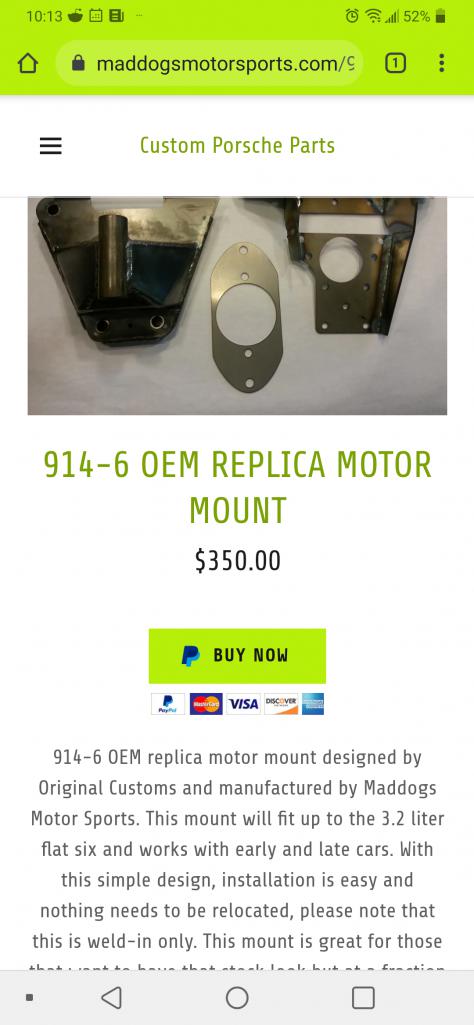
Posted by: RichPugh Oct 3 2020, 03:33 PM
I woke up dreaming about this last night, sad but true, so I should probably figure out an approach and just be done with it.
I am leaning towards mounting the Naro Mount as instructed on the firewall, thereby not having to deal with the rear brake stuff, but extending the engine mount up by adding in additional steel plate.
The thickness of the additional steel plate will move the engine back away from the firewall and I should be able to readily raise the bolt holes by the 3/4 of an inch necessary.
@md911 I think that’s what you suggested, and it seems like a viable option I’ll be at with some heartburn from having to fabricate and shape the new mounting surface.
One open question that I don’t believe it’s been addressed – it looks to me like the Naro Mount may transmit more in VH then one that uses regular engine mounts. Yes/no/maybe?
First off... Definitely more vibration. It's essentially a solid mount just with a urethane bushing.
I think i'm gonna do the same thing... Weld a new "U" shaped plate to the existing one and re-drill the mounts about 3/4" - 7/8" higher and the thickness of the new face should push it back almost enough to put the trans mounts square in their seats. It might need another 1/4" spacing off the case... will find out. Pulling the engine back out tomorrow
Posted by: Tdskip Oct 3 2020, 03:55 PM
I woke up dreaming about this last night, sad but true, so I should probably figure out an approach and just be done with it.
I am leaning towards mounting the Naro Mount as instructed on the firewall, thereby not having to deal with the rear brake stuff, but extending the engine mount up by adding in additional steel plate.
The thickness of the additional steel plate will move the engine back away from the firewall and I should be able to readily raise the bolt holes by the 3/4 of an inch necessary.
@md911 I think that’s what you suggested, and it seems like a viable option I’ll be at with some heartburn from having to fabricate and shape the new mounting surface.
One open question that I don’t believe it’s been addressed – it looks to me like the Naro Mount may transmit more in VH then one that uses regular engine mounts. Yes/no/maybe?
First off... Definitely more vibration. It's essentially a solid mount just with a urethane bushing.
I think i'm gonna do the same thing... Weld a new "U" shaped plate to the existing one and re-drill the mounts about 3/4" - 7/8" higher and the thickness of the new face should push it back almost enough to put the trans mounts square in their seats. It might need another 1/4" spacing off the case... will find out. Pulling the engine back out tomorrow
Frustrating to be sure.
Not sure I want to deal with the NVH...
Posted by: live free & drive Oct 3 2020, 04:50 PM
The Naro mount has Delrin bushings - the Patrick mount has urethane bushings with a steel center sleeve -which I believe to be a better set up for anything but a full-on race car (NVH-wise).
Posted by: Tdskip Oct 24 2020, 03:09 PM
Interesting - I just welding the Naro mount in 3/4 inch higher than directions but did NOT have to adjust the transmission mounts at all. It located the rear mount perfectly - like totally bang on perfect. I am running a 3.2 but don’t think that makes any real difference.
Maybe the slant of the firewall is enough to better locate it once it is mounted higher?
Posted by: RichPugh Oct 24 2020, 03:27 PM
I assumed that same result if I had welded it higher. Did you have trouble with room for the rear brake bias valve?
Posted by: Tdskip Oct 24 2020, 03:59 PM
I assumed that same result if I had welded it higher. Did you have trouble with room for the rear brake bias valve?
I removed it but don’t think I actually had to. I did screw up in that I left the line to it under the mount rather than on top but that is fixable.
I was under the gun to get the drivetrain in so I could move the car so I punted on that for today.
Posted by: JOEPROPER Nov 6 2020, 10:55 AM
@http://www.914world.com/bbs2/index.php?showuser=18068 How did you make out with that engine mount?
Posted by: RichPugh Nov 11 2020, 10:58 AM
@http://www.914world.com/bbs2/index.php?showuser=18068 How did you make out with that engine mount?
I was able to ignore it while procrastinating and doing nothing. Well, doing other stuff, completely unrelated to the 914, as per the 914 project handbook, "Step 4: Stop working on 914 and do other stuff".
LOL
I'm planning to finish the stuff in the front this week or next... I.e., putting the fresh air blower box and fan back in, wiring and plumbing the fuel pump, dropping the tank back in... THEN I can roll it off the lift, spin the lift around, put it BACK up in the air with the lift positioned where I can remove the engine... and THEN I'll stare at the mount until I repeat step 4 again.
The goal is to weld a new plate to the face of the engine side of the mount with the holes positioned up 3/4"-1" upwards... that should do it.
-Rich
Powered by Invision Power Board (http://www.invisionboard.com)
© Invision Power Services (http://www.invisionpower.com)