Printable Version of Topic
Click here to view this topic in its original format
914World.com _ 914World Garage _ Time to un-DAPO the "new" car
Posted by: BillC Jun 27 2020, 11:30 AM
So, I bought a "new" 914 a few weeks ago (a '73 2.0). When I received it from the shipper, I noticed was the seller was quite artful about his pictures, with what was and what wasn't shown. And, now that I've had a chance to start taking things apart, I have uncovered quite a bit of DAPO-done-damage, and I'm sure there's more hiding somewhere (oh boy! something to look forward too....). Some of the damage appears to have been there for a loooong time.
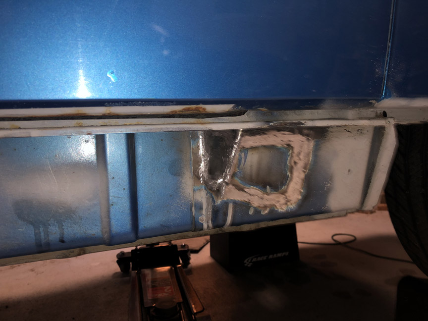
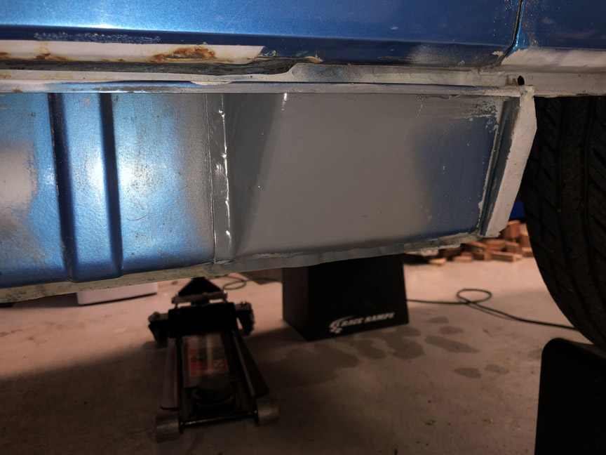
I've already received a piece from a scrap car to fix this hole: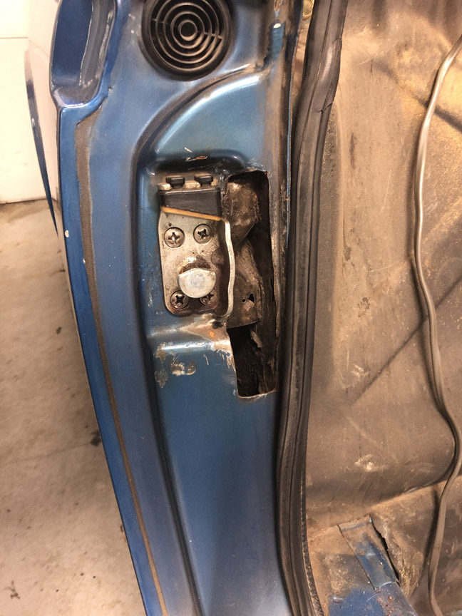
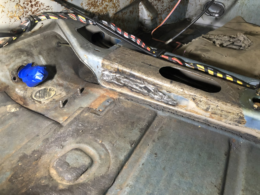
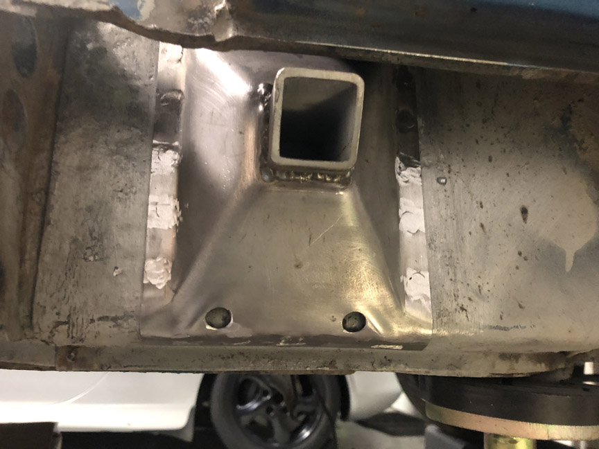
Once I took the rockers off, I discovered this:
Yes, they hole-sawed through FOUR layers of sheet metal, including the heat duct. Not sure what they were thinking, but there it is.
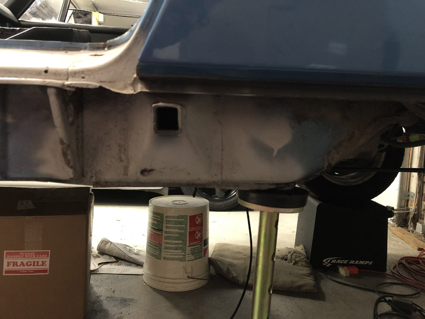
In the trunk, I found three hole-sawed holes. I think they might have been thinking about mounting the fuel pump in a 75/76 blister, but they never finished the work (and also picked the wrong location).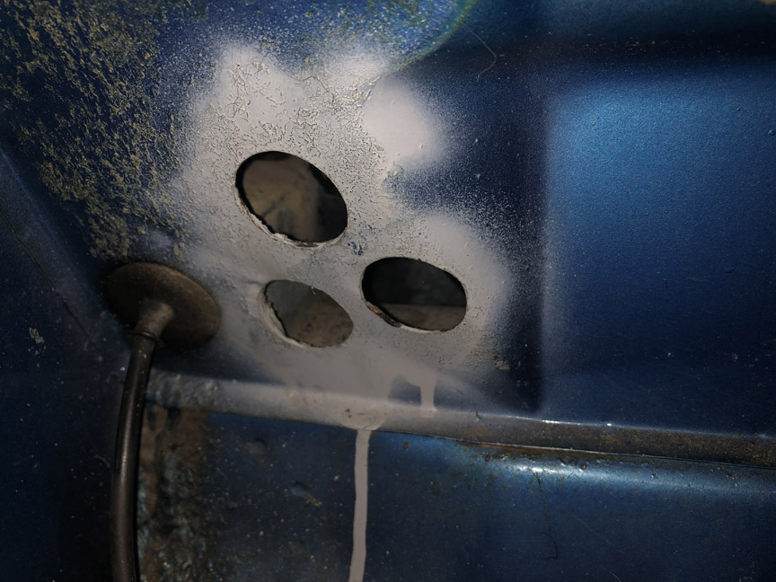
Posted by: Montreal914 Jun 27 2020, 11:32 AM
Front mounted oil cooler or AC? 
Look for holes at the feet of the passenger side.
Posted by: SirAndy Jun 27 2020, 11:43 AM

Front mounted oil cooler or AC?
Look for holes at the feet of the passenger side.

Posted by: BillC Jun 27 2020, 12:06 PM
Front mounted oil cooler or AC?
Look for holes at the feet of the passenger side.
Possibly, but no holes inside on the passenger side. If that's what they were doing, then they gave up before finishing.
But wait! There's more:
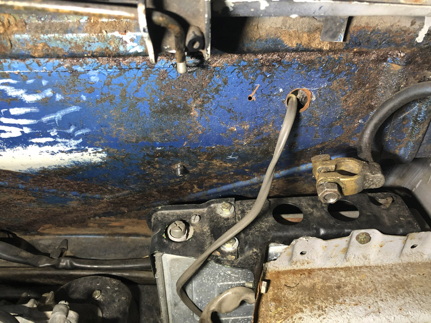
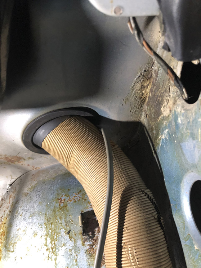
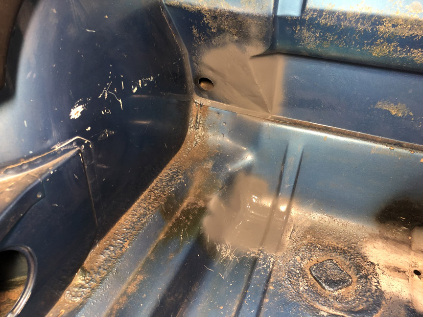
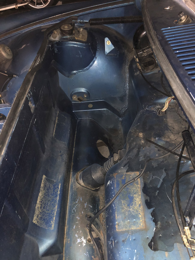
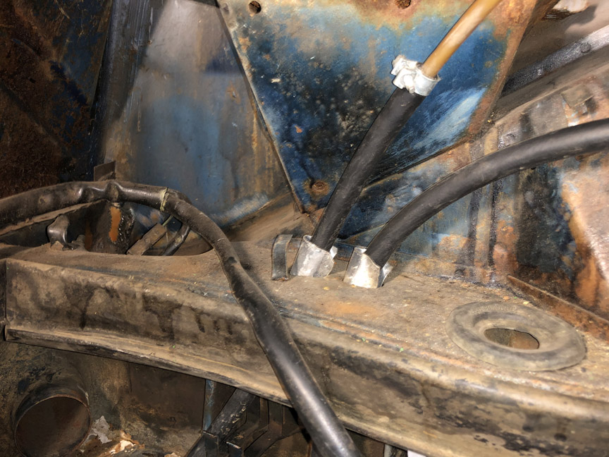
They did front-mount the fuel pump. However, for whatever reason, they decided to run the wiring for the pump through the passenger compartment. And, they drilled a hole in the firewall above the EFI computer to do it (notice, no grommet).
The wire runs between the passenger seat and the longitudinal, and then up into the front trunk through the grommet for the heat air tube and then down under the tank to the pump. Once I get a chance to pull the tank, I'll be able to see how that is mounted.
Posted by: BillC Jun 27 2020, 12:16 PM
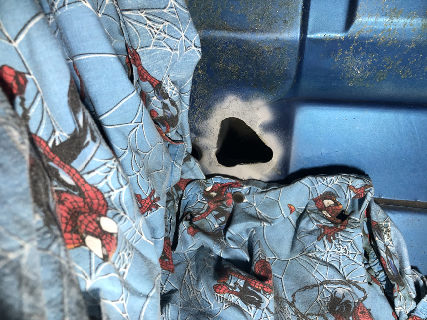
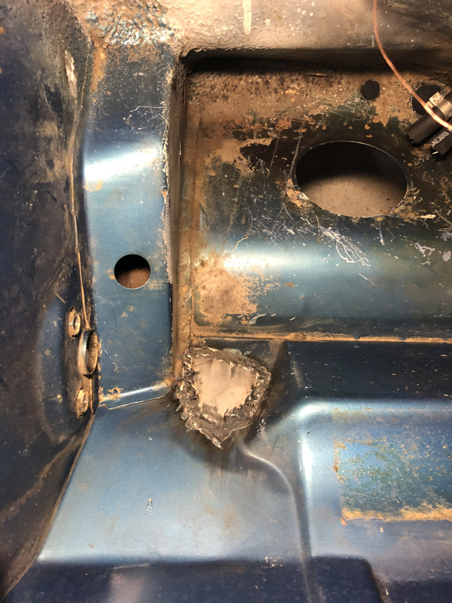
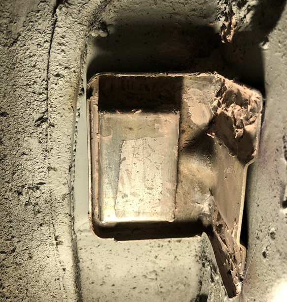
But, so far, the "best" has to be the hole they hacked into the center tunnel, near the pedals. 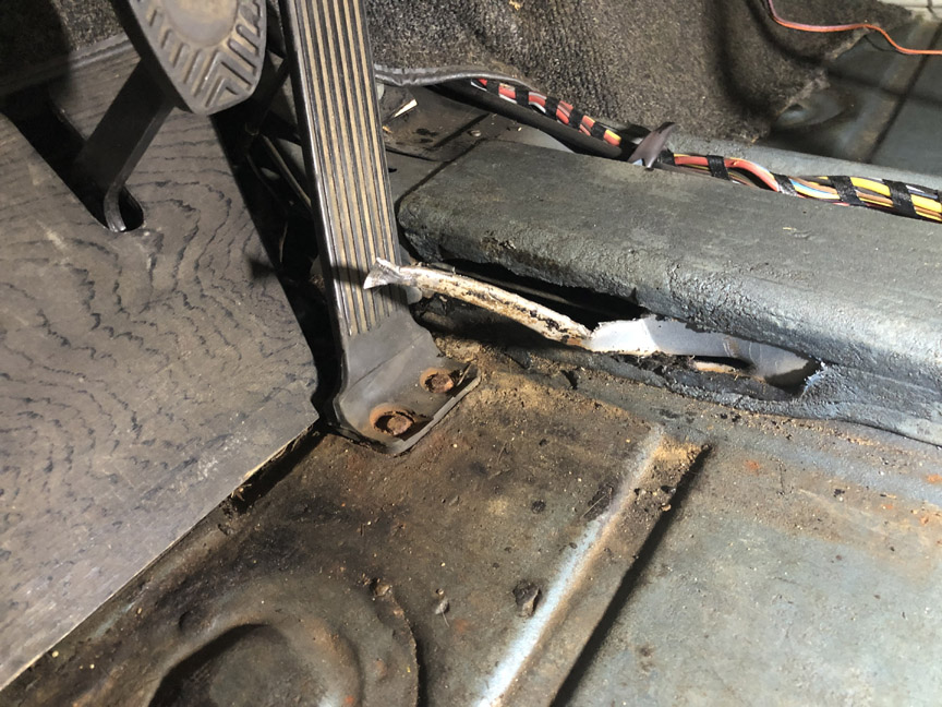
My guess is that they were changing the cables, and wanted easier access to the tunnel. So they took an air chisel and hacked their way in. And they left the piece they cut loose.
Here's the hole without the hacked piece.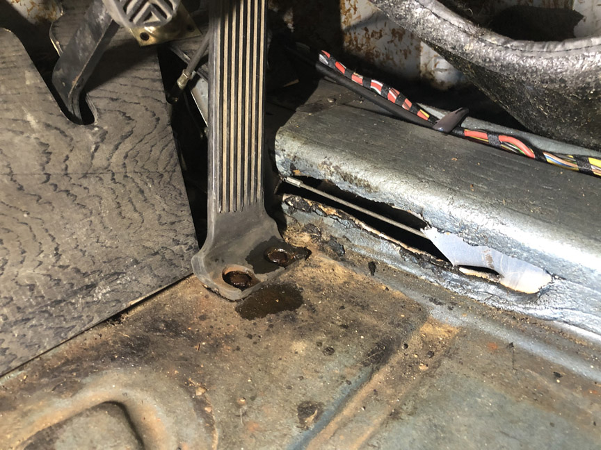
I cut it off with a pair of snips. I'll take a look at welding the piece back in, so at least I still have the piece, even though it needs to be reshaped.
Posted by: BillC Jun 27 2020, 12:23 PM
And, in the archaeology department, here's a couple of interesting things I found:
According to the maintenance records, the first owner of the car was a woman. It looks like she wore a lot of bobbi pins, since here's what I found on the driver's side and in the center console: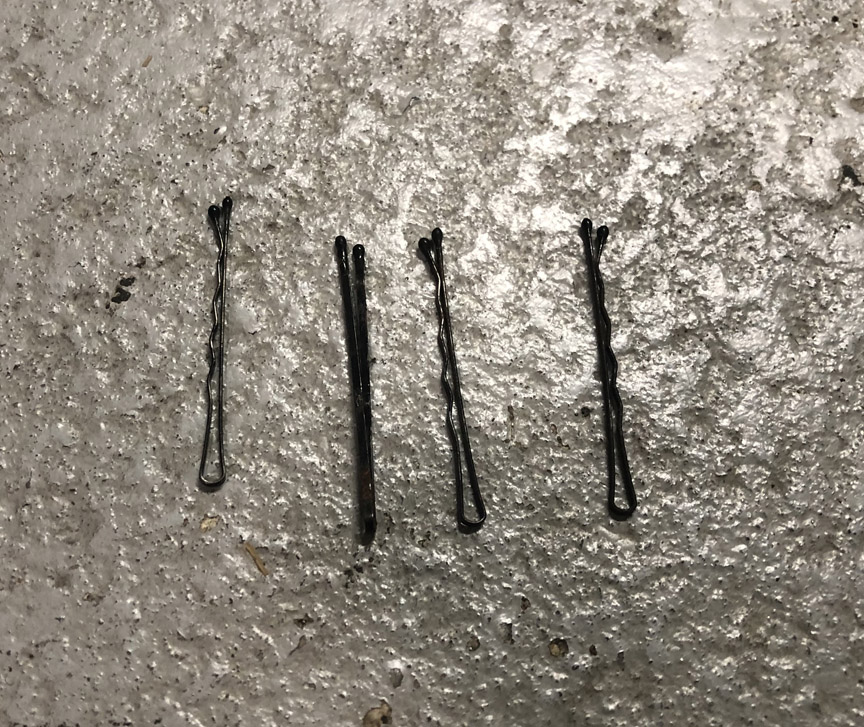
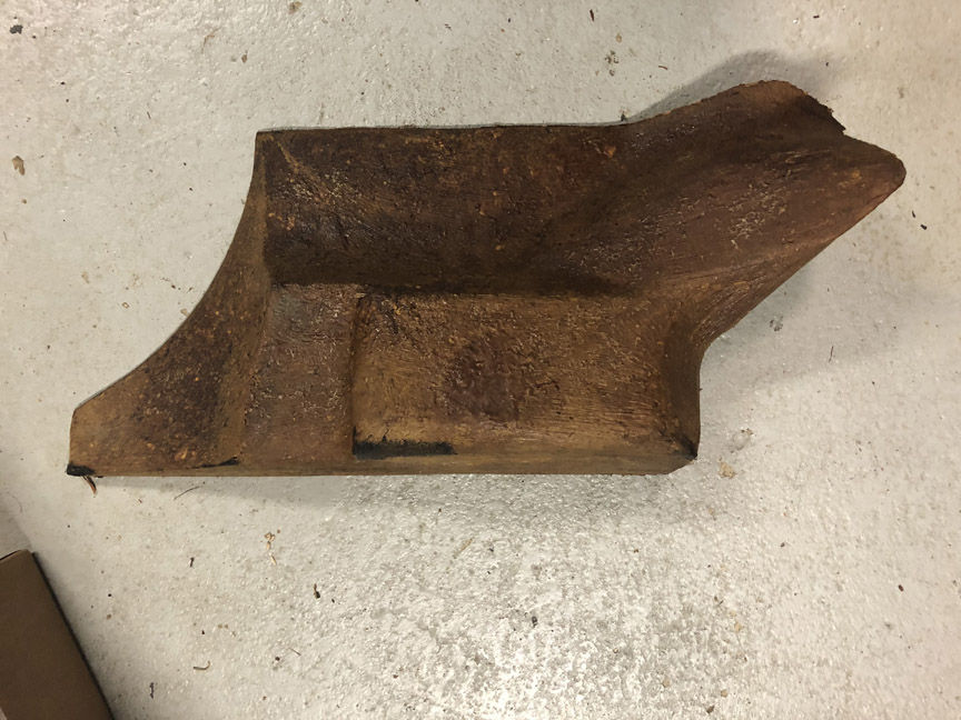
Also, when I first pulled the floor mats, I saw a bit of brown on the front firewall. I just assumed someone had made a replacement floorboard out of particle board. However, once I got the front carpet out, I discovered it was actually a molded piece of hard urethane foam.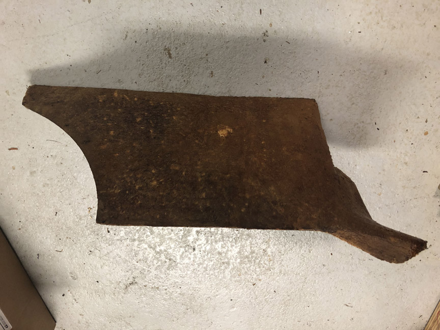
Has anyone seen this before? It's new to me, previous car didn't have one.
And, is a floorboard supposed to go over this? Or, is this the floorboard?
Posted by: BillC Jun 27 2020, 12:27 PM
It turns out that the car may have it's original spare tire.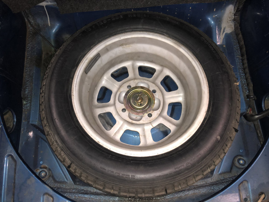
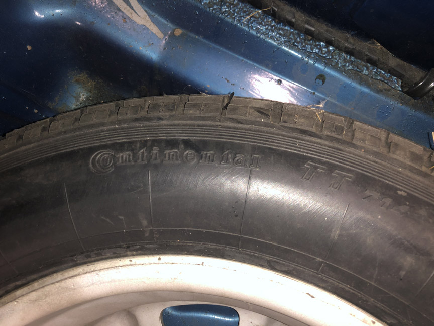
It's a bias-ply Continental in 165R15, and still looks pretty nice on the top side (inside).
It doesn't hold air anymore, so I'm going to replace it with a new tire at some point. However, if some CW would like the tire for a concours display, just pay shipping and I'll send it to you after I get it replaced.
Posted by: Chris914n6 Jun 27 2020, 12:30 PM
The foam is factory correct for an early car. It's smaller than the later cars. A piece of carpet is fitted over it.
Posted by: BillC Jun 27 2020, 12:44 PM
The foam is factory correct for an early car. It's smaller than the later cars. A piece of carpet is fitted over it.
According to the Karmann production number, this car was made on 5 March 1973. My previous 914 was built in the last week of April 1973. This car has the foam wedge, but my previous car had a wooden floorboard and no foam.
Did these two cars fall across a running change? Or, did someone replace the foam wedge on my previous car with a wood board?
Posted by: SirAndy Jun 27 2020, 03:01 PM
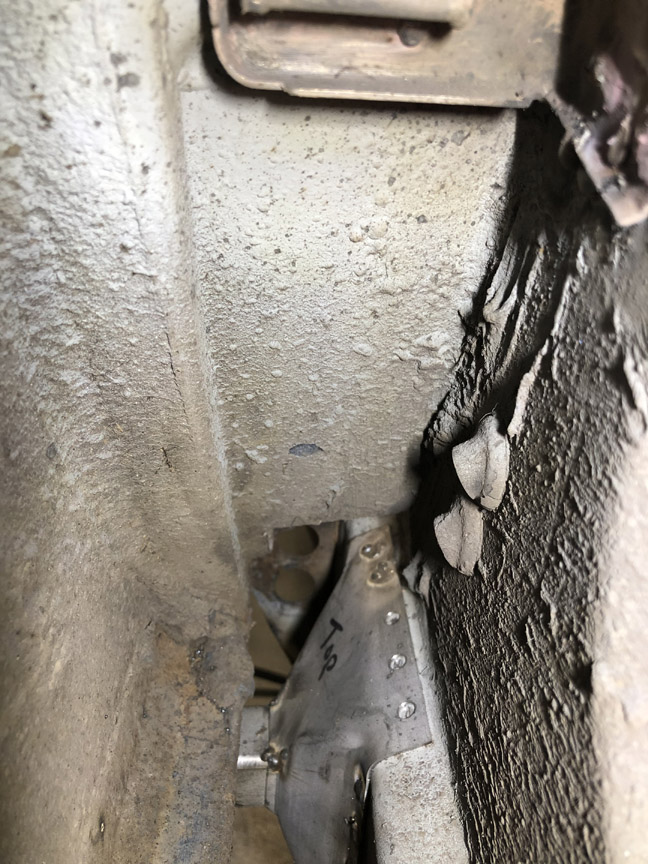
They were trying to weld/secure the broken clutch tube.
Do a search here on how to fix this correctly and make sure it is done well before you close that back up.

Posted by: ClayPerrine Jun 27 2020, 03:17 PM
Trying to "Un-DAPO" the car.
I am still working on that myself!!!! 

I still want to know why they cut a hole behind the door latch.
Posted by: mepstein Jun 27 2020, 04:11 PM
The foam is factory correct for an early car. It's smaller than the later cars. A piece of carpet is fitted over it.
According to the Karmann production number, this car was made on 5 March 1973. My previous 914 was built in the last week of April 1973. This car has the foam wedge, but my previous car had a wooden floorboard and no foam.
Did these two cars fall across a running change? Or, did someone replace the foam wedge on my previous car with a wood board?
I think your previous car might have been modified. All the cars I've bought (about 20) either had foam or nothing. I thought it was some sort of compressed sawdust with a binder.
Posted by: ClayPerrine Jun 27 2020, 04:46 PM
The foam is factory correct for an early car. It's smaller than the later cars. A piece of carpet is fitted over it.
According to the Karmann production number, this car was made on 5 March 1973. My previous 914 was built in the last week of April 1973. This car has the foam wedge, but my previous car had a wooden floorboard and no foam.
Did these two cars fall across a running change? Or, did someone replace the foam wedge on my previous car with a wood board?
I think your previous car might have been modified. All the cars I've bought (about 20) either had foam or nothing. I thought it was some sort of compressed sawdust with a binder.
It is definitely molded, compressed sawdust coated with shellac on the outside. I took the one for the 4.0L and carved out grooves for the DME wiring. Man what a mess! Once the outer layer was gone, that stuff went everywhere. By the time I got done, I was yellow with sawdust.
Posted by: BillC Jun 27 2020, 05:22 PM
They were trying to weld/secure the broken clutch tube.
Do a search here on how to fix this correctly and make sure it is done well before you close that back up.
Hmmm, good point. I'll definitely have to check that. It might also explain why they removed the clutch pedal stop from the driver's floor board. If that is the case, then they didn't fix it, since there's no sign of welding or other repair anywhere near the cable tube.
Trying to "Un-DAPO" the car.
I am still working on that myself!!!!
I still want to know why they cut a hole behind the door latch.
I believe the hole was cut to remove rust, so a new piece could be welded in. However, while the DAPO(s) could obviously operate drill bits, a hole saw and a cut-off wheel, I haven't found any signs of them doing any actual welding on the car. And trust me, this car is going to need a lot of welding to fix the DAPO damage.
 Fortunately, not as much welding as would normally be expected to fix rust, so that's a little relief.
Posted by: Cairo94507 Jun 27 2020, 05:42 PM
I hope they disclosed all of those issues prior to the sale. Or, in the alternative, I hope you got a great deal. 
Posted by: preach Jun 27 2020, 05:49 PM
It turns out that the car may have it's original spare tire.
It's a bias-ply Continental in 165R15, and still looks pretty nice on the top side (inside).
Here is my potential original from a 1972 I just picked up.
http://www.914world.com/bbs2/index.php?act=Attach&type=post&id=746212
I also have an Opel that I think I may have been the dumb arse prior owner of.
Posted by: BillC Jun 27 2020, 06:06 PM
I hope they disclosed all of those issues prior to the sale. Or, in the alternative, I hope you got a great deal.
No, and no.
In the seller's defense, I don't think he knew about all the problems, since he seemed more like someone who would take the car somewhere rather than work on it himself.
And, I got a reasonable deal on the car, but not a great one. If I had known about all of these issues, I would have pushed harder for a lower price. Once the car is fixed, it should be a good car. I think I'll live with the funky paint job for a while, before I worry about getting it repainted.
Posted by: BillC Jun 27 2020, 06:23 PM
So, continuing down the list of discoveries:
There was a mess of wires hanging down under the dash. Most of it is for the aftermarket radio, but there was one wire connected to a toggle switch under the dash.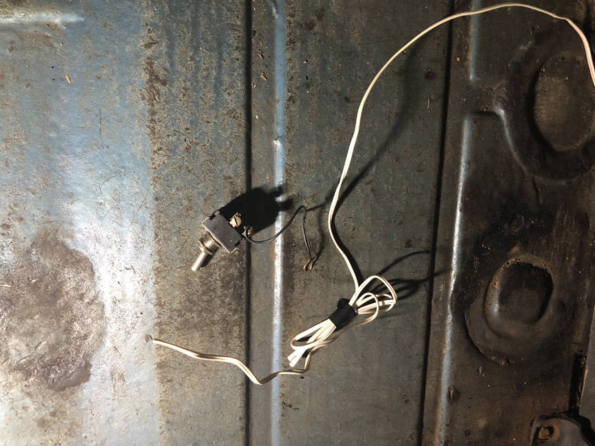
One end of the switch was connected to ground. I dug into the dash and discovered the other end was spliced into the tach wire from the coil. So, it appears to be a shade-tree anti-theft device, grounding the coil to kill the ignition. However, that might also explain why the tach doesn't work.
Here are a couple more pics of how the fuel pump wire ran through the passenger compartment: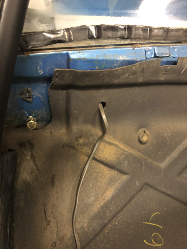
Speaking of holes in the firewall, I found this lovely on the driver's side: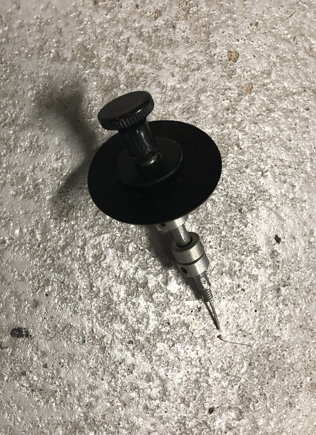
It wasn't connected to anything, but may have been a remote trunk release. Although, other than the hole in the firewall, I didn't find any other holes related to it.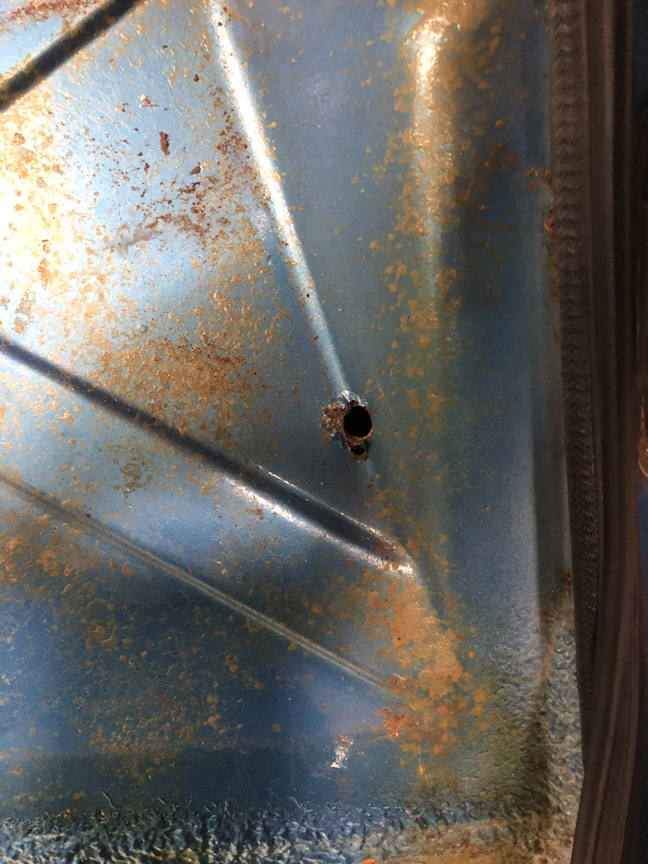
The fuel pump wire hole and the pull handle hole are the largest holes drilled in the firewall, but there are at least 10 other holes of various sizes drill in it.
Under the car, I discovered that the original vinyl fuel hoses are still in the center tunnel. However, they did splice in new hoses between the firewall and the engine compartment (stock vinyl hoses in the engine compartment, too).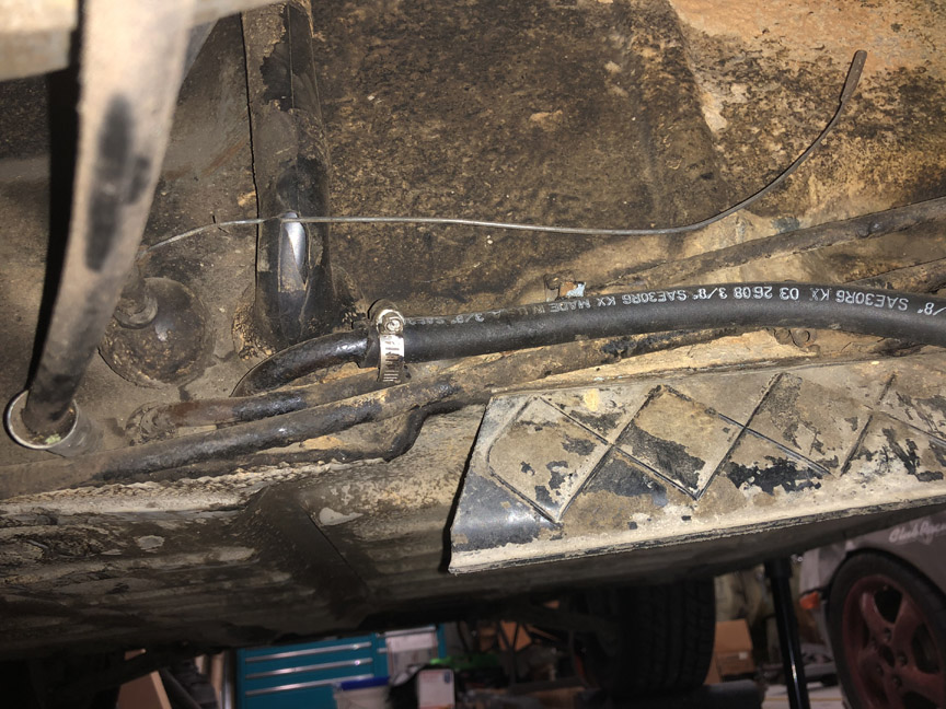
And, of course, none of the heating parts are connected. They did install new stainless heat exchangers and a muffler. However, they are for a 1.7, not a 2.0. But, they did not replace the muffler hanger with the correct one. Instead, they drilled new holes to move it upward and then created home-made adapter brackets to connect it to the muffler.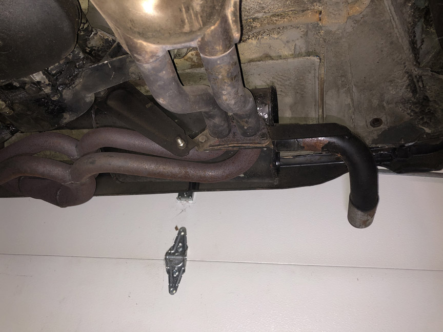
It turns out that the stainless heat exchangers are in really nice shape. Any chance anyone might want to trade these for some nice 2.0 exchangers? I'll eventually post pics in a "trade" post on the for-sale board, after I get a chance to wash them off.
Tomorrow, the plan is to drain the fuel, drop the engine and pull the tank (if there's time). Who knows what fun is lurking under the tank?
Posted by: barefoot Jun 28 2020, 01:35 PM
The 1.7/1.8 SS heat exchangers have the same tube sizes as the 2.0. so no need to replace them. If you're anal about the muffler bracket you can easily find a 1.7/1.8 version.
have fun with the other fixes.
Posted by: BillC Jun 28 2020, 05:48 PM
The 1.7/1.8 SS heat exchangers have the same tube sizes as the 2.0. so no need to replace them. If you're anal about the muffler bracket you can easily find a 1.7/1.8 version.
have fun with the other fixes.
Yeah, I know the tubes are the same size, and that the 1.7 exchangers will work just fine. However, I am kinda anal about making the car "right". And, I'd rather reinstall the exchangers just once if I can, rather than put these in for now and change them later on.
Posted by: BillC Jun 29 2020, 10:56 AM
So, we got the engine and fuel tank out yesterday. And, the DAPOs didn't disappoint.
On the engine, where the Decel Valve should be, I found this: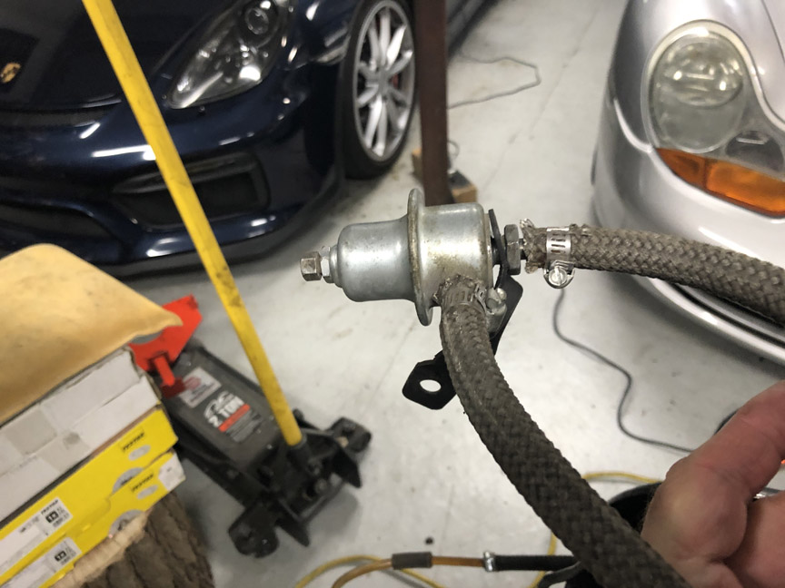
Yup, that's a fuel pressure regulator on a home-made mounting bracket. It does look similar to a decel valve, but they're just not quite the same thing. Plus, they didn't bother connecting or plugging the vacuum line that connects to the decel valve, so there's the source of the high idle.
In the front, they did mount the fuel pump and filter under the tank. However, they did it by using a sheet metal screw to attach a hose clamp and then clamped the pump, with a little bit of old hose for noise dampening.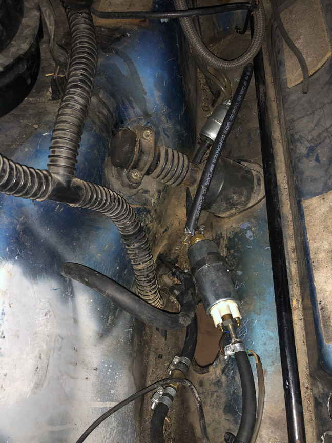
Not really a great mount, but probably the least "DAPO" thing they did to the car.
The previous owner did mention that the car seemed to lose power at higher speeds. I think I may have found out why: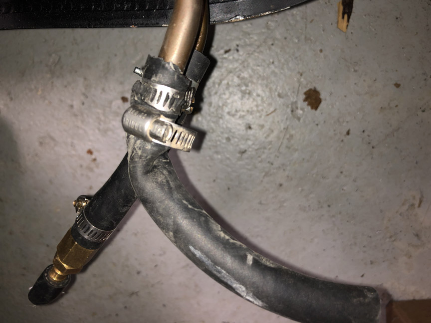
Apparently that crimp isn't enough to stop the car from running, but came very close. Also explains why it took so long to drain the fuel tank.
Posted by: SirAndy Jun 29 2020, 12:25 PM
For what it's worth, i really like the color!

Posted by: BillC Jul 1 2020, 04:12 PM
For what it's worth, i really like the color!
Thanks! So do I.
Well, it's finally time to put up or shut up. Up 'til now, I've been complaining about what has been done to the car over the years, now it's time to actually do something about it.
Sunday, we pulled the engine and trans from the car. Monday, I spent time removing more stuff from the car. Yesterday, I pushed the engine-less car out of the garage and hosed out as much dirt as I could from the frunk, the gas tank area and under the rear trunk. No pictures of any of this, figured it was kinda boring and yesterday was quite soggy.
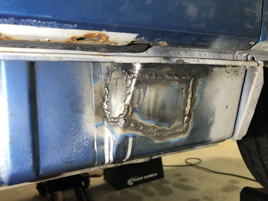
Today is the start of the metal repairs. I started with the holes in the divider panel between the gas tank and the frunk. Here's what it looked like to start:
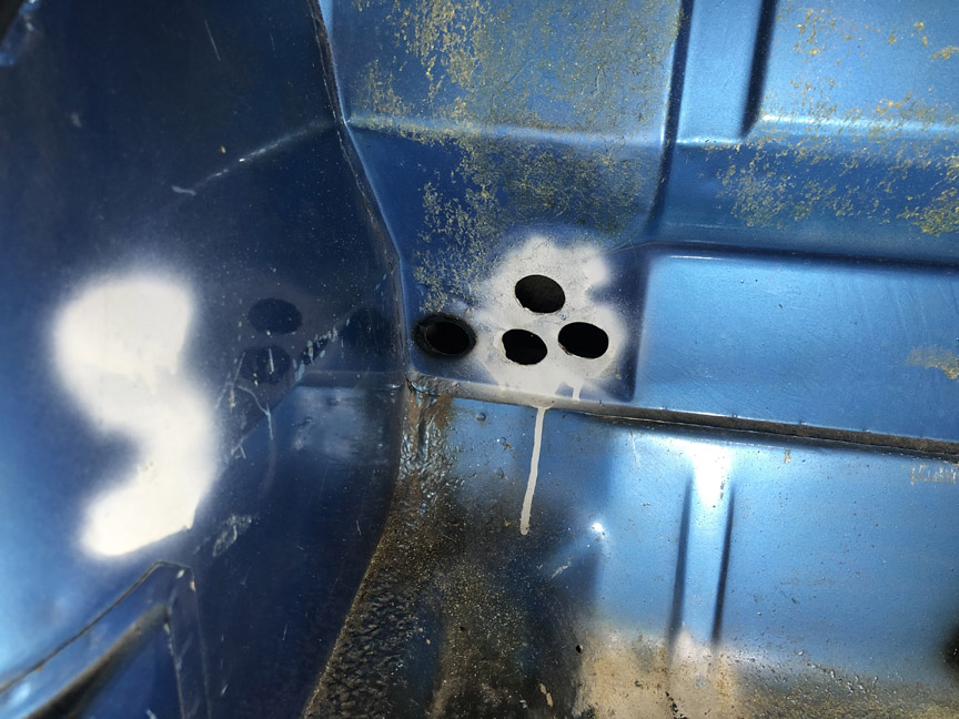
To start, I cut out the "web" between the holes, to make one large hole, which seemed easier to patch than 3 smaller holes.
Then, I put a piece of cardboard behind the hole and used a pencil to outline out a patch. I cut out the cardboard, traced it on a piece of sheet metal and then cut out the piece of metal. Here's a pic of the patch tacked in place.
Then I got to work, welding and grinding. Here are a couple of pics of the patch installed and cleaned up (outside and inside):
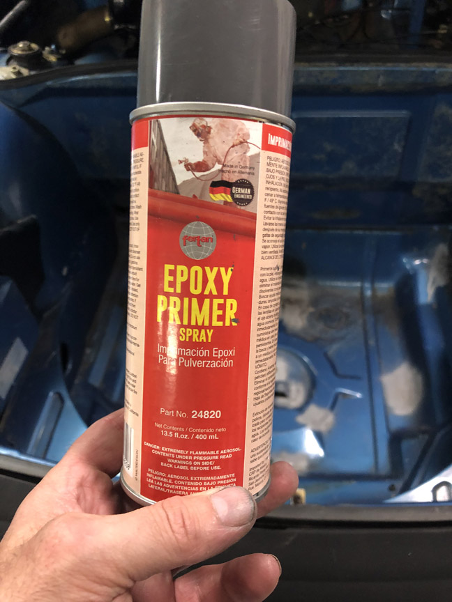
And, with a coat of primer:
It seemed appropriate to use the primer that I won at Octeenerfest three years ago:
Posted by: Craigers17 Jul 1 2020, 04:43 PM
This situation seems particularly frustrating....especially on what look like some otherwise pretty solid longs. Did they really have to go through 4 frigg'n layers? It's really hard to imagine what the intended result was supposed to be.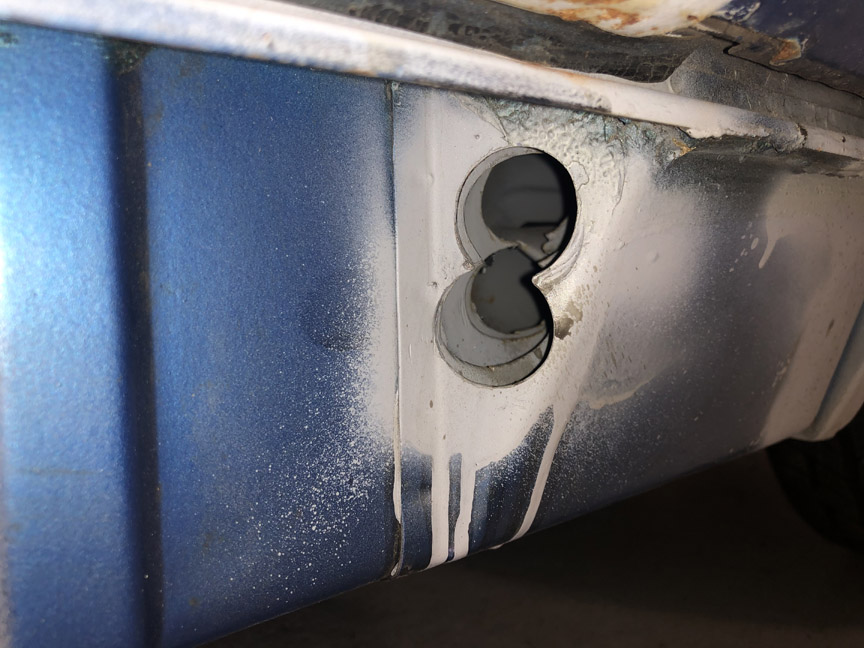
Posted by: 2mAn Jul 1 2020, 04:56 PM


Posted by: Superhawk996 Jul 1 2020, 05:02 PM
This situation seems particularly frustrating....especially on what look like some otherwise pretty solid longs. Did they really have to go through 4 frigg'n layers? It's really hard to imagine what the intended result was supposed to be.
My guess is AC lines. My car had similar butchery from AC install
Posted by: Wyvern Jul 1 2020, 05:03 PM
When I started reading this I did not know what a "DAPO" was ... but each time I saw it i got a better idea , now I know . LOL
My buddy and I have talked about making a book PO FU ... but that may be a better name .
We need a DAPO thread
Posted by: BillC Jul 1 2020, 05:22 PM
This situation seems particularly frustrating....especially on what look like some otherwise pretty solid longs. Did they really have to go through 4 frigg'n layers? It's really hard to imagine what the intended result was supposed to be.
Yes, very frustrating. They went through three layers of structural metal and the heating duct. The worst part is that I have to cut big holes in the three structural layers to get to the heat duct and then rebuild things on my way out.
My guess is AC lines. My car had similar butchery from AC install
No idea. Someone else had previously suggested oil cooler lines. Could have been either, or something else entirely. Whatever it was supposed to be, they didn't complete it -- other than the frunk divider, there are no other holes where you'd expect AC or oil cooler lines to be run (at least, that I have found).
When I started reading this I did not know what a "DAPO" was ... but each time I saw it i got a better idea , now I know . LOL
My buddy and I have talked about making a book PO FU ... but that may be a better name .
We need a DAPO thread
I learned about "DAPO"s on this forum, too. Very fitting acronym.
If someone starts a thread, I'll be nominating the picture that Craigers picked out.
Posted by: BillC Jul 2 2020, 05:19 PM
Made more progress today.
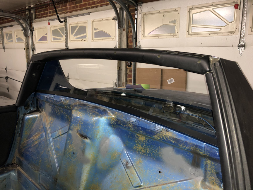
Removed the rear window and the engine deck lid. Found another thing that needs to be fixed -- apparently they stripped out the nut for the deck lid mount, so they drilled it out and dropped a bolt in from above. Was originally thinking of just putting a helicoil in to fix the welded nut, but it may have been drilled out too large for that, will measure tomorrow.
Welded up the holes in the firewall, Also wirebrushed the rusty areas on the firewall and the window mounting area. Treated the rust with Loctite Rust Converter, which will get primered and painted after it dries.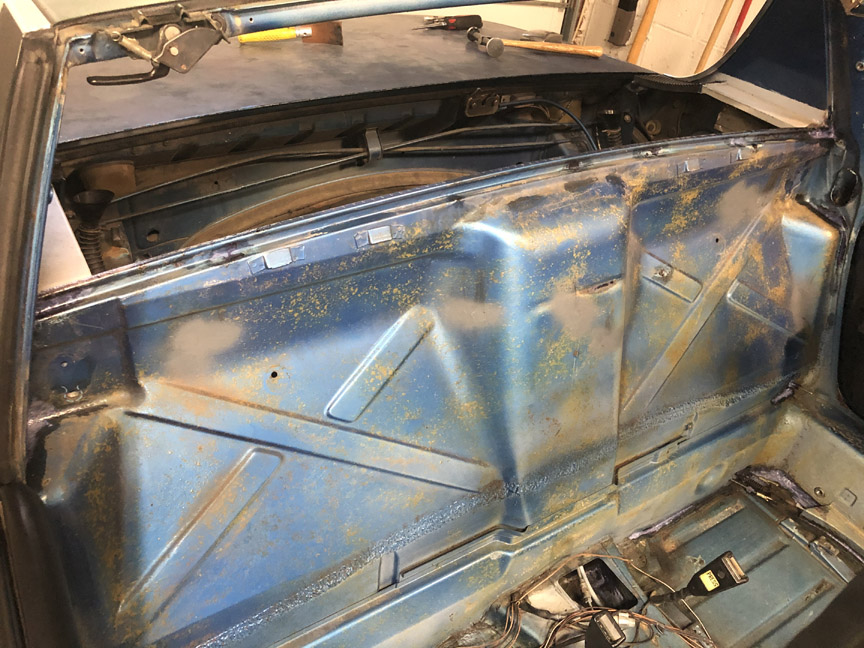
Also, the touch-up paint finally arrived from Paintscratch.com (we're having UPS problems). So, I touched up the frunk and gas tank areas. Looking much better: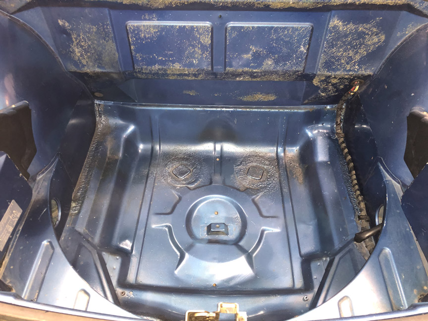
Posted by: Montreal914 Jul 2 2020, 05:50 PM
Not sure what your front sway bar setup is but I don't see any reinforcement plate on the inner wall, is it mounted on the wheel well side? Or was the factory installed sway bar didn't have the added plate?
Posted by: BillC Jul 2 2020, 05:53 PM
Not sure what your front sway bar setup is but I don't see any reinforcement plate on the inner wall, is it mounted on the wheel well side? Or was the factory installed sway bar didn't have the added plate?
It's a factory-installed sway bar, so no added plate on the inside. The mounting plates are spot-welded on the outside with multiple spots.
Posted by: BillC Jul 3 2020, 04:44 PM
It doesn't seem like I accomplished much today, but it took all day to do it.
I installed a new retractable antenna. Had to leave the old antenna base grommet, since the area of affected paint is larger than the new base.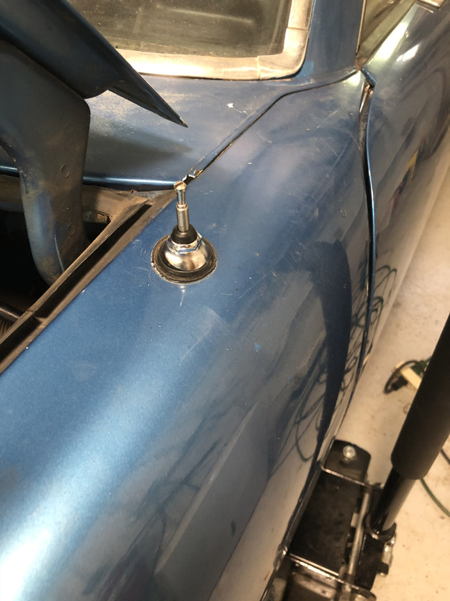
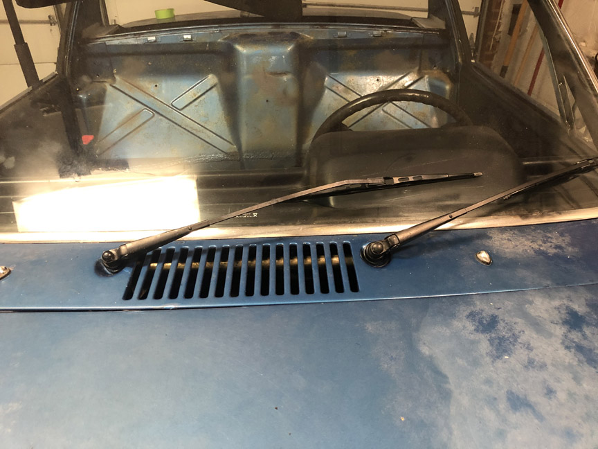
Then, I removed the windshield wiper assembly. I cleaned up and treated the rust around the wiper post holes. Then, I disassembled the wiper assembly and cleaned and greased the posts.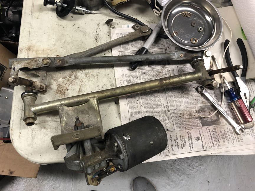
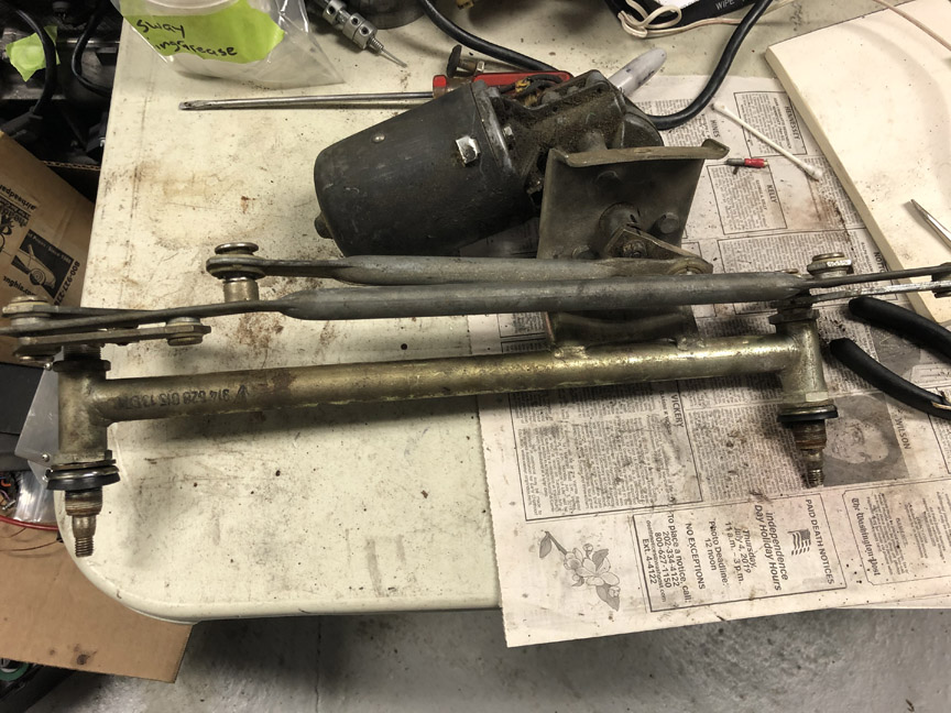
Hopefully, tomorrow I'll be able to paint around the post holes and then Sunday I'll be able to reinstall the wiper assembly.
I also installed new hoses for the window washers, while I have easy access under the cowl. At some point, I'll install an electric pump for the washer.
Posted by: BillC Jul 6 2020, 04:26 PM
Well, I didn't make as much progress as hoped this weekend.
I went to reinstall the window wiper mechanism, and ended up breaking the 47-year-old rubber isolator mount. <sigh> So, time to order another part and wait for it to arrive. Hello, 914Rubber....
In the meantime, I fixed the control cables for the heating & ventilation system. Don't know why, but some of the cables were connected to the wrong locations.
And, I fixed the stripped nut in the decklid mount. Since (I hope) everyone likes pictures, I took a bunch of this process. Of course, it took as long to take all the pics as it did to perform the actual repair.
First step is to drill out the bad threads. Fortunately, the DAPO didn't over-drill the hole, it was just about the right size.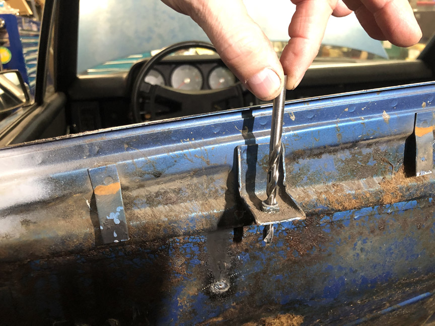
Then, I tapped the hole with the helicoil tap: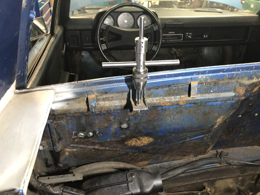
Then, to make sure the helicoil won't come out, I added some red loctite.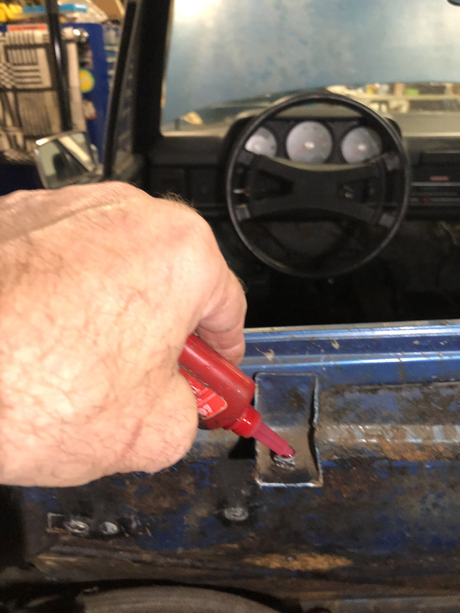
Next step was to install the helicoil insert. Here's a pic of the install tool, with the insert about halfway installed: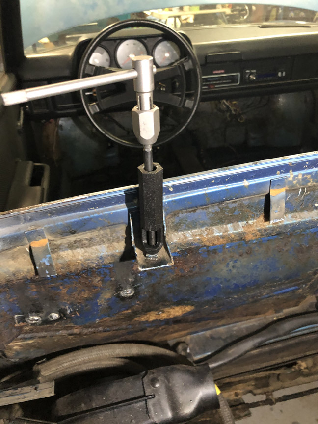
Final step was to break off the driving tang. The full kit comes with this special "breaker" tool (aka, a piece of steel rod), but it can be done with a screwdriver if you just buy the basic kit.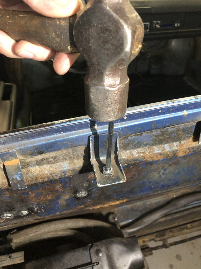
All done. This won't come out without destroying the mount.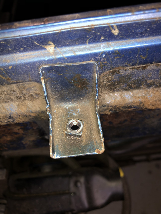
Posted by: Cairo94507 Jul 6 2020, 05:54 PM
Very nice. You are making great progress and tackling things one at a time will keep you from getting over loaded.
Posted by: Front yard mechanic Jul 6 2020, 08:07 PM
If you ever sell the car think what the next owner will call you 
Posted by: BillC Jul 7 2020, 06:36 AM
If you ever sell the car think what the next owner will call you
Well, among other things, I am trying to avoid being lumped into the same category of (future) previous owners.
The guy who bought my previous 914 seemed very happy with it, and that includes having it shipped to a well-known 914 shop for a thorough inspection prior to receiving the car.
Posted by: IronHillRestorations Jul 7 2020, 03:16 PM
Sad to see the misfortune of some cars. I hope my 2nd 914 never shows up here. I'd be curious as to the cost of the car Bill, if it was a high dollar car or not.
Posted by: get off my lawn Jul 7 2020, 03:20 PM
If you ever sell the car think what the next owner will call you
LOL note to self: don't sell a car to anyone on 914world
Posted by: Superhawk996 Jul 8 2020, 06:40 AM
If you ever sell the car think what the next owner will call you
Well, among other things, I am trying to avoid being lumped into the same category of (future) previous owners.
The guy who bought my previous 914 seemed very happy with it, and that includes having it shipped to a well-known 914 shop for a thorough inspection prior to receiving the car.

Let's be honest - over the course of 40+ years, lots of these cars have had work done on them by people that that should have at least learned to work on a lawnmower before undertaking repairs on an automobile.

Congratuations @http://www.914world.com/bbs2/index.php?showuser=18667 for taking the time and effort to fix it with a sense of quality and workmanship that was often lacking in the orignal reapirs we find on these cars.
Posted by: BillC Jul 9 2020, 07:08 PM
The order with the rubber isolator finally came, so I installed the wiper motor and wipers.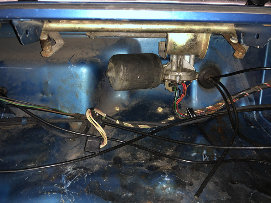
The hardest part of the installation is the nut for the other end of the isolator. It hides under the dash, and is very difficult to reach with the dash in place. Fortunately, if you take out the ashtray mount (two phillips screws and push forward to unclip), you can just barely get access with a 1/4" drive deep socket (10mm) and a universal joint. The red circle shows the inside nut.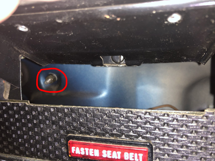
Posted by: BillC Jul 11 2020, 04:19 PM
Today I worked on reinstalling the fresh air box. With a new top gasket and intake screen (came on '74 and later 914s), it was every bit the royal pain that they said it was. But, here is the box installed: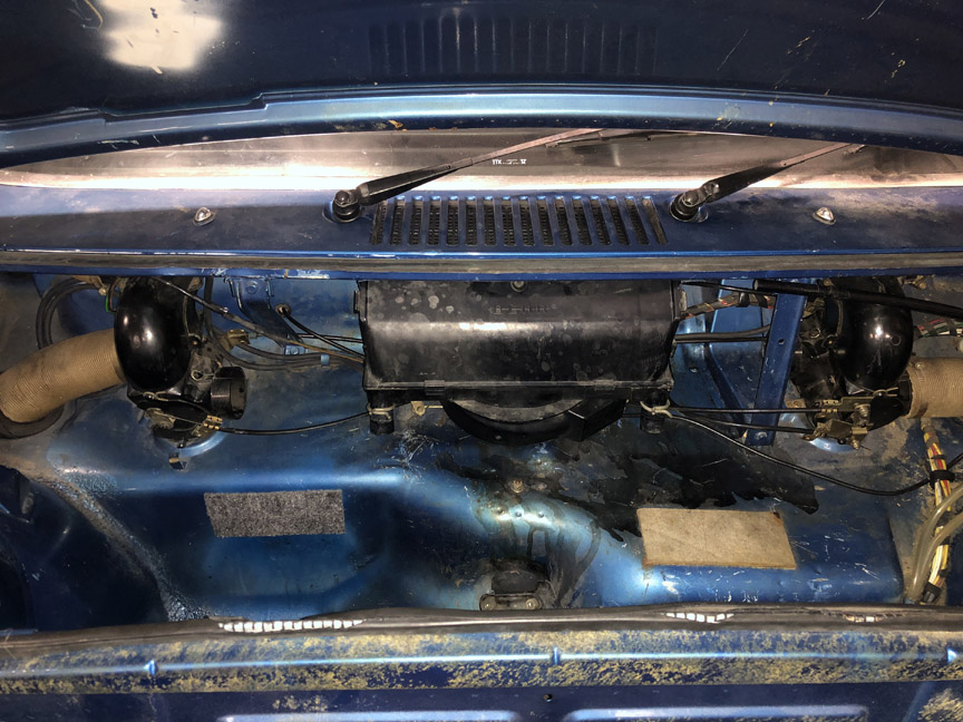
Because it was such a pain to get the two bolts installed, I had to get creative. I got the driver-side bolt in okay, but couldn't get the box high enough to get the passenger-side bolt in. So, I decided to make a "mini jack" with a tall socket and a brake pad spreader.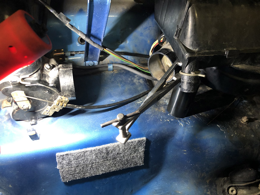
This got it up high enough to get the last bolt in.
Then, I connected the cable to the fan box. This was almost as big a pain as installing the box itself. No pics, since I had to do the job basically by feel.
Then, the hoses were reinstalled. First the paper hoses to the ventilation system and then the drain hoses. One of the old hoses broke, so I had to get new hoses (from AA). Unfortunately, they don't quite match the old ones, so I'll order some from 914Rubber, next time I place an order.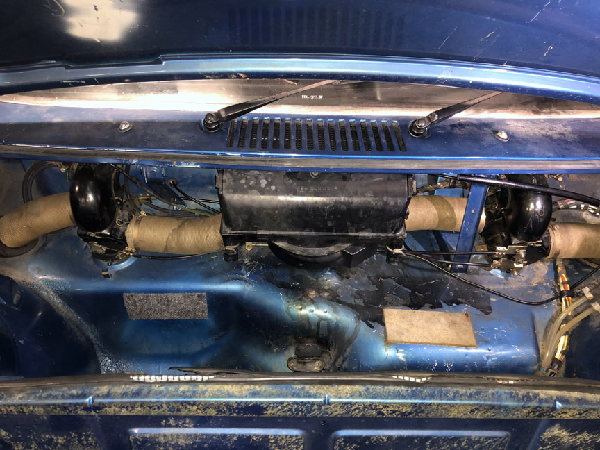
Posted by: BillC Jul 12 2020, 02:39 PM
Time to tackle the hacked-in hole by the foot pedals. Here's what it looked like before I started: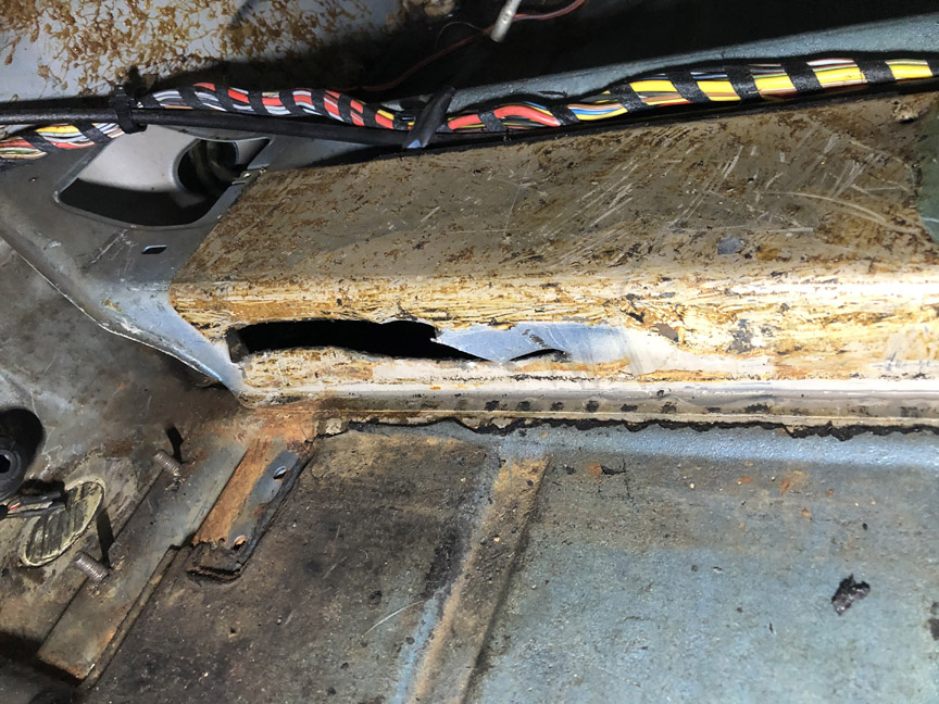
I didn't really want to cut another hole in the car, but there was no way I was going to be able to reform the hacked metal without an access hole on top of the center column. The bit in the top of the hole is the old accelerator cable -- the liner was stuck in the tube and I needed the access hole to get the liner out through the front end of the tube. Once I'm all done with the welding and painting, I'll make a panel to cover the hole, which will be attached with butyl rubber so it can be accessed in the future.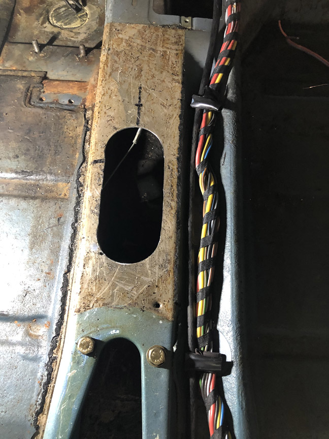
Here's the hole and the patch (what was originally cut loose) after reshaping.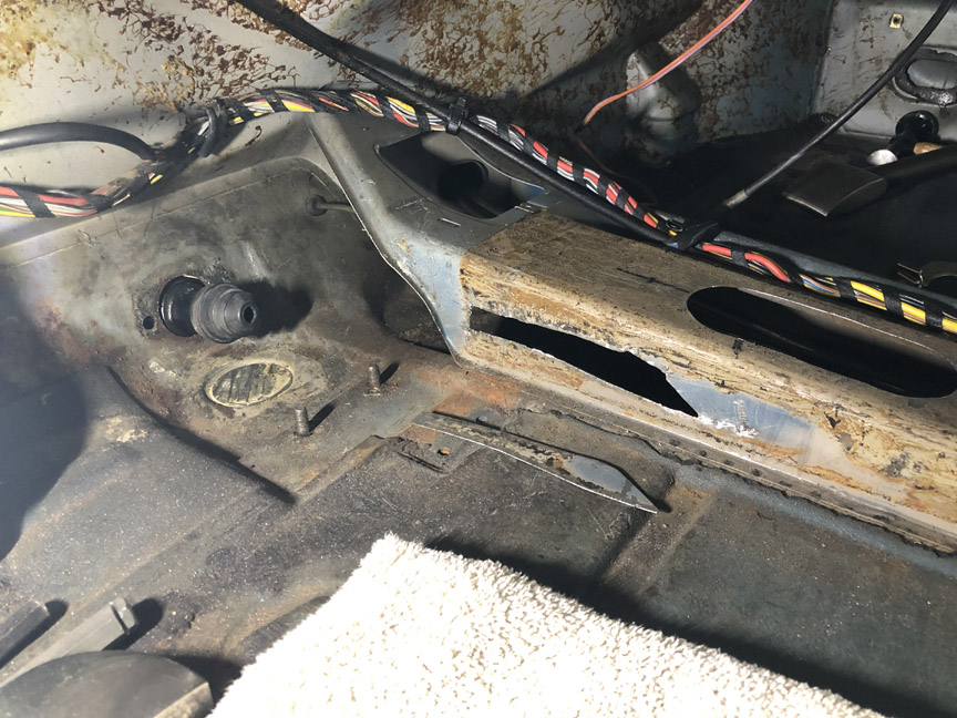
And the patch fitted in place. There's a copper bar behind the patch, to act as a temporary backing plate for the welding.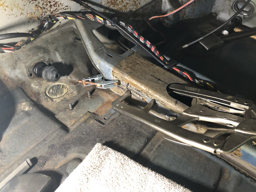
Patch welded and then ground.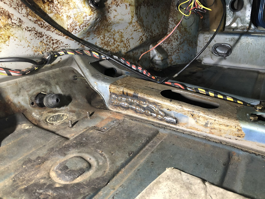
Here's what the clutch tube looked like: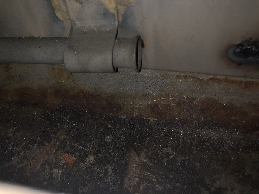
Even though the clutch tube still looks well-attached, I decided I might as weld in a support strap while I had easy access to it. I bent a piece of 3/16" wire into a loop about 5/8" inside diameter. Then, I drilled two holes, above and below the clutch tube, and placed the strap.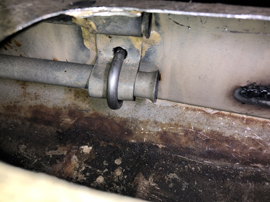
Here's the strap welded to the tube support. Not the greatest welding job (access wasn't good, even with the access hole), but it should hold.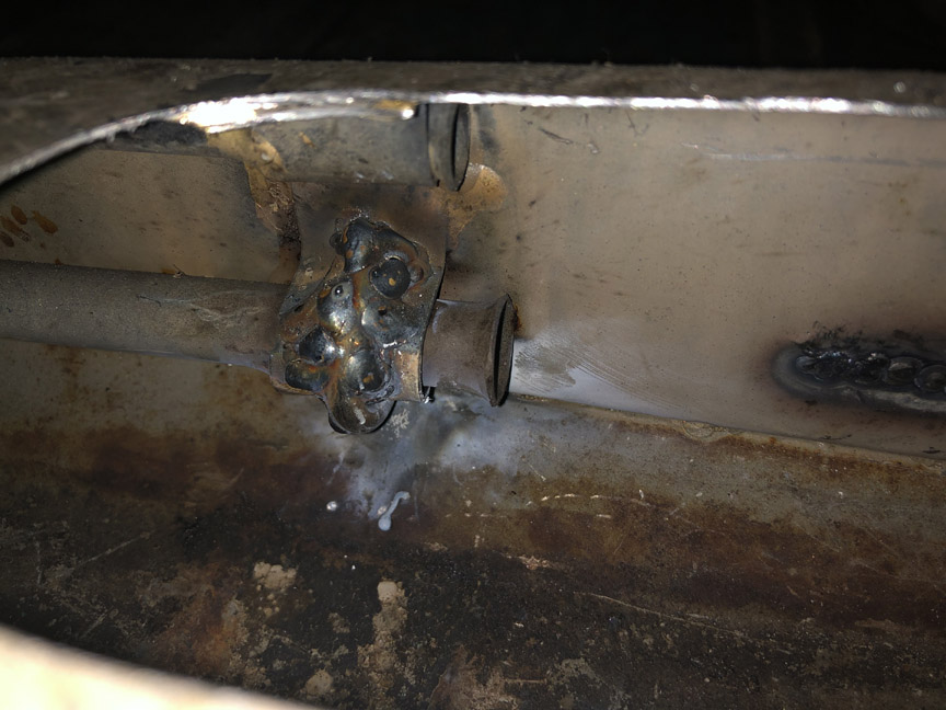
On the outside of the center column, you can see where the strap protruded.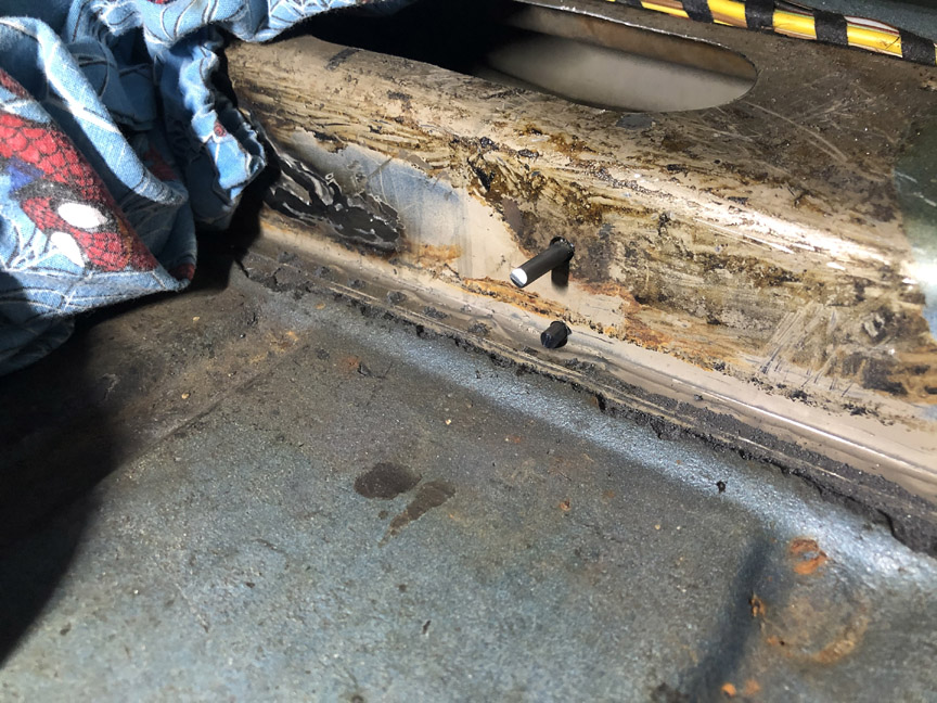
So I trimmed the ends of the strap in preparation for welding: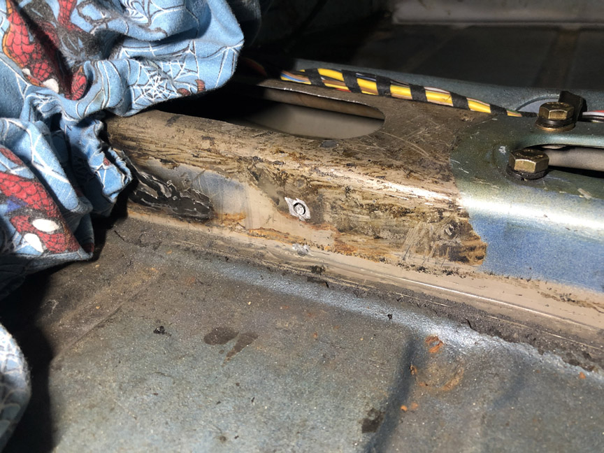
Here's the final result, after welding and grinding: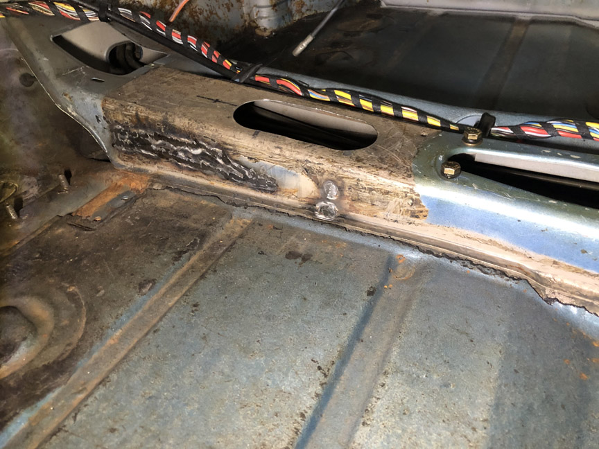
Posted by: 914werke Jul 12 2020, 03:00 PM
Good idea on the Wire support.
Posted by: Superhawk996 Jul 12 2020, 03:58 PM
Like the wire support execution.
My donor tunnel came with two threaded rod hooks made and had nuts external to the tunnel to pull them tight. Rather unelegant but functional.
I like your solution since it won't be visible of leave a wart on the side of the tunnel. Nice Job. 
Out of caution you might want to make sure that the weld penetration hasn't entered the clutch tube which would cause the cable to hang up later on when trying to feed it though. Check now if you're not sure. Better to find out now rather than later when access is limited again.
Posted by: BillC Jul 12 2020, 07:17 PM
Like the wire support execution.
Thanks, but it's basically the same idea as the cable clamp Clay Perrine suggested way-back-when, just without the nuts.
Excellent suggestion -- already tested it and no impingement inside the tube.
Posted by: ClayPerrine Jul 12 2020, 09:50 PM
Like the wire support execution.
Thanks, but it's basically the same idea as the cable clamp Clay Perrine suggested way-back-when, just without the nuts.
Excellent suggestion -- already tested it and no impingement inside the tube.
Betty and I installed the cable clamp in her car back when we were first married, over 30 years ago. We didn't have the money, time or location to tear the tunnel apart and fix it right. It is still on the car, but the car is in the body shop now so I am going to have them fix it right when the rest of the body work is done.
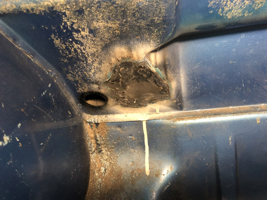
Posted by: BillC Jul 13 2020, 07:17 PM
And now, let's go after this lovely bunch of holes: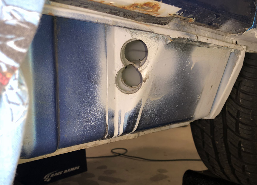
First step is to cut access holes in the outer three layers: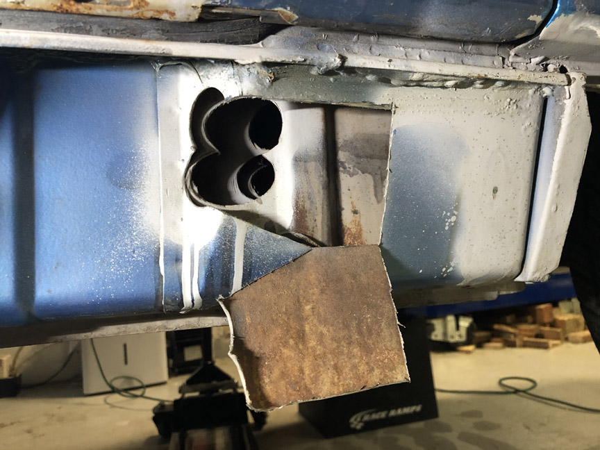
I found this little surprise inside the first layer. You can just see it in the bottom of the hole in the above picture. It's one of the bits that was hole cut -- it fell inside and was left there. Unfortunately, it's useless as a patch, so it goes in the scrap bin.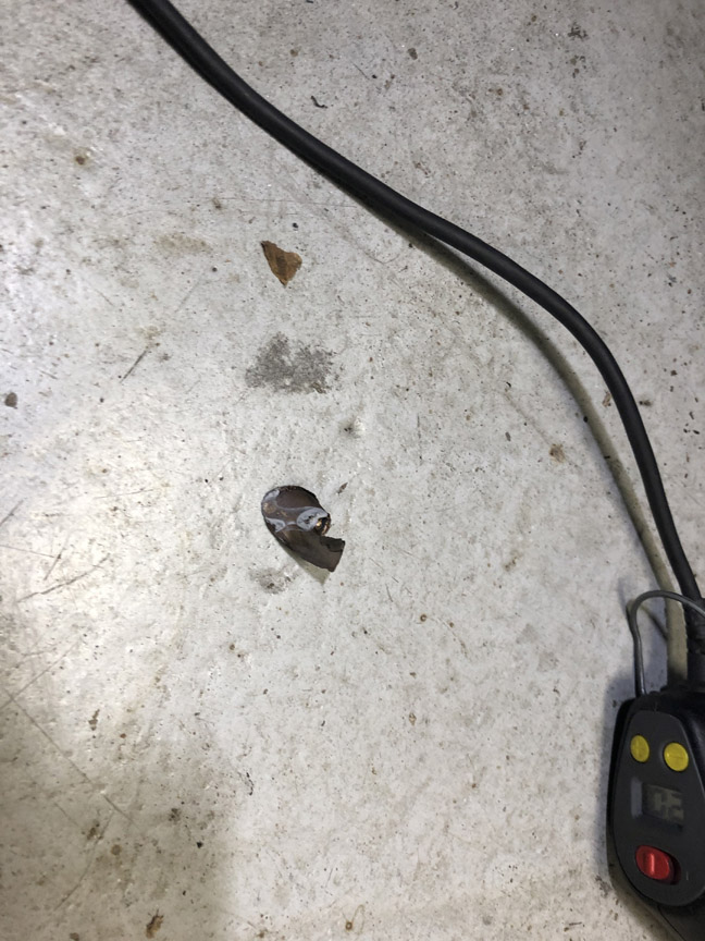
Second layer access: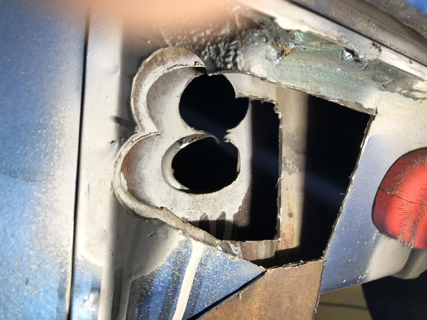
The cut pieces for the first two layers will be saved and welded back in later.
Then, the third layer.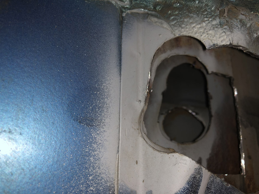
Once I got a little further into making the patch for the innermost hole, I realized I needed to make the third layer hole a little larger. I'll just make a larger patch later.
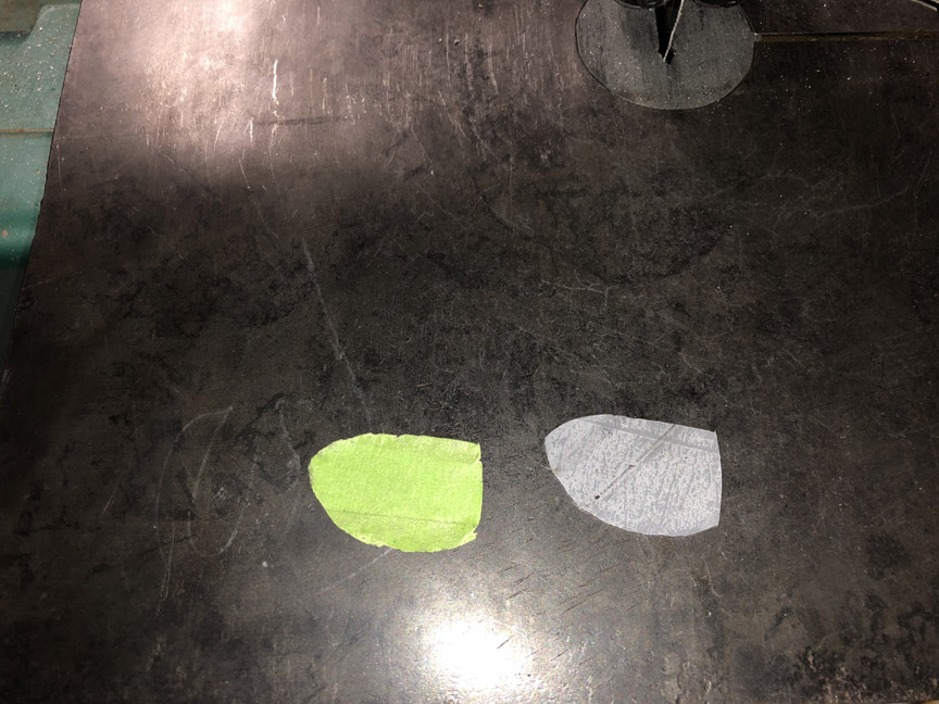
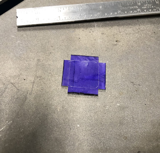
Now it's time to make a patch for the innermost layer, the heat duct tube. This is the masking tape method. First, put masking tape over the hole: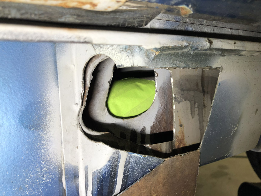
Then, use an x-acto knife and cut out the tape over the hole: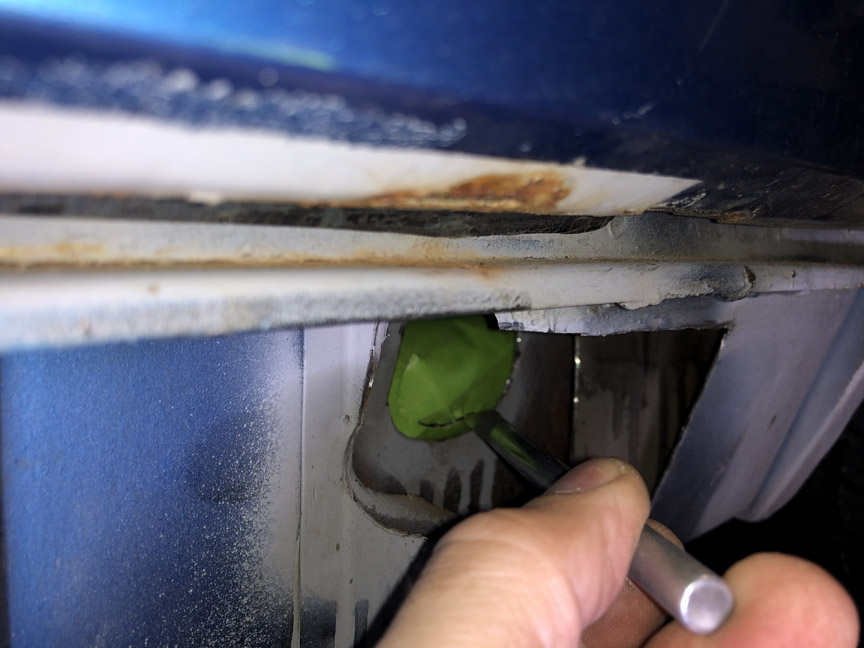
Remove the cut piece and place it on a piece of sheet metal: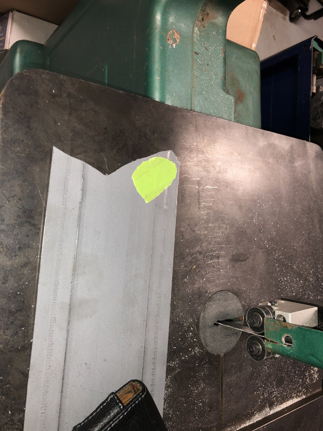
Then, cut out the piece of sheet metal, and you have your patch: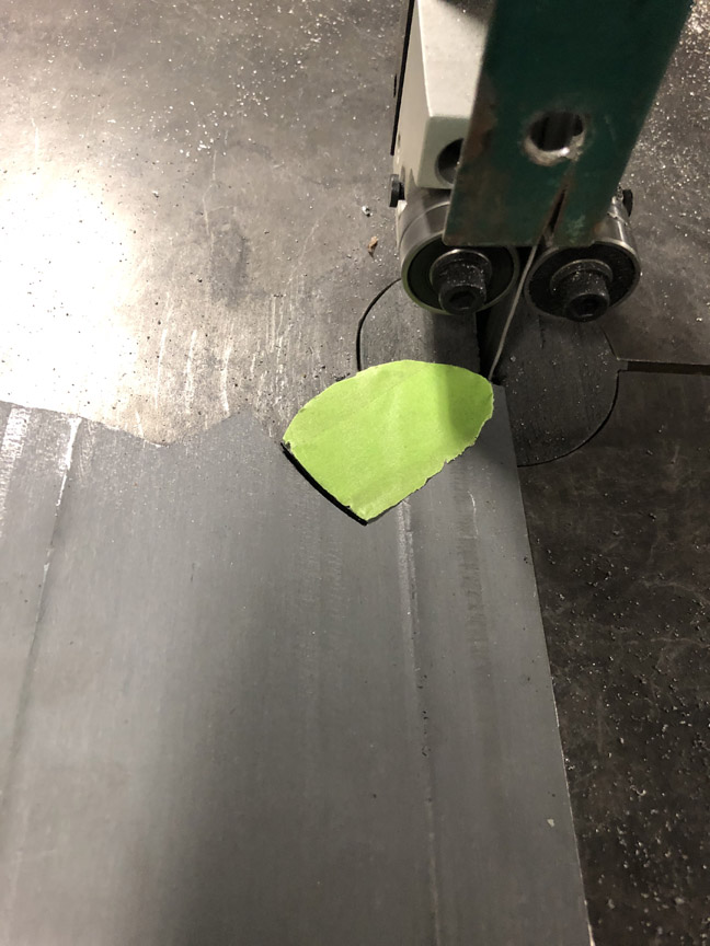
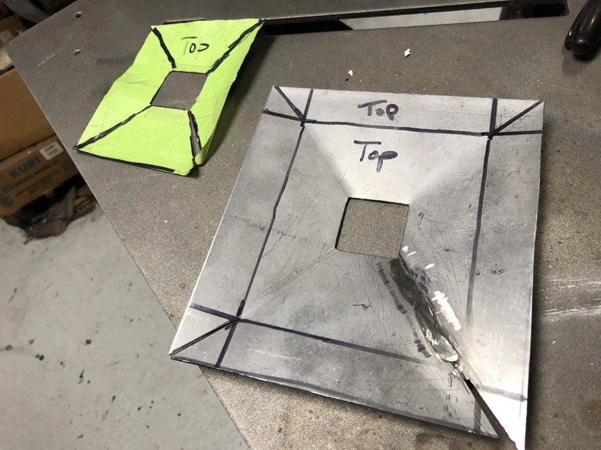
Since this patch goes on a tube, I found a socket that's about the same diameter as the tube and shaped the patch over the socket.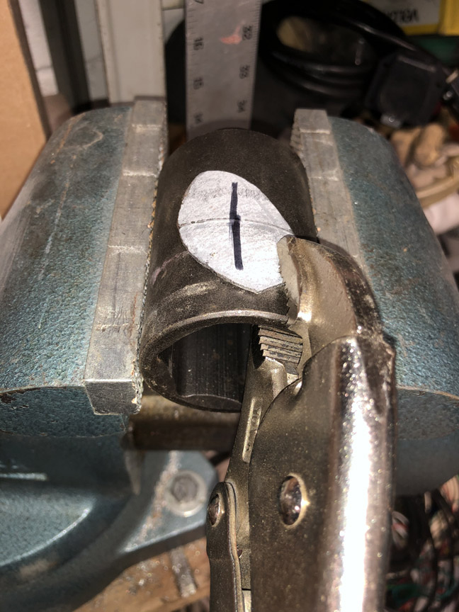
Posted by: BillC Jul 13 2020, 07:29 PM
The lovely bunch of holes, continued:
Here's the first patch in place. The screw is used as a handle to place the patch. After the patch is tacked in place, the screw will be removed and the hole welded over.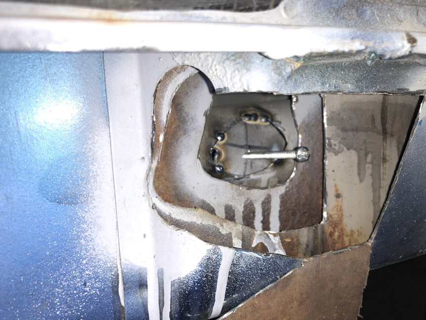
And all welded up: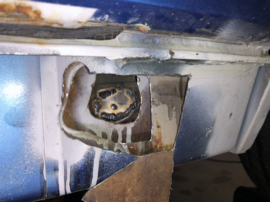
I'm not going to bother grinding down the welds inside the hole. No one will see them once this is all done, and they will add a little strength.
I use the masking tape method to make all of the patches to replace missing metal. I'll spare you the repeated steps and just show each major step completed.
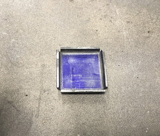
Here's the third layer patch completed: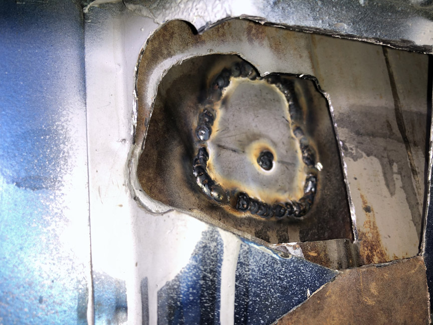
The first part of the second layer patch -- re-attaching the piece that was cut out for access: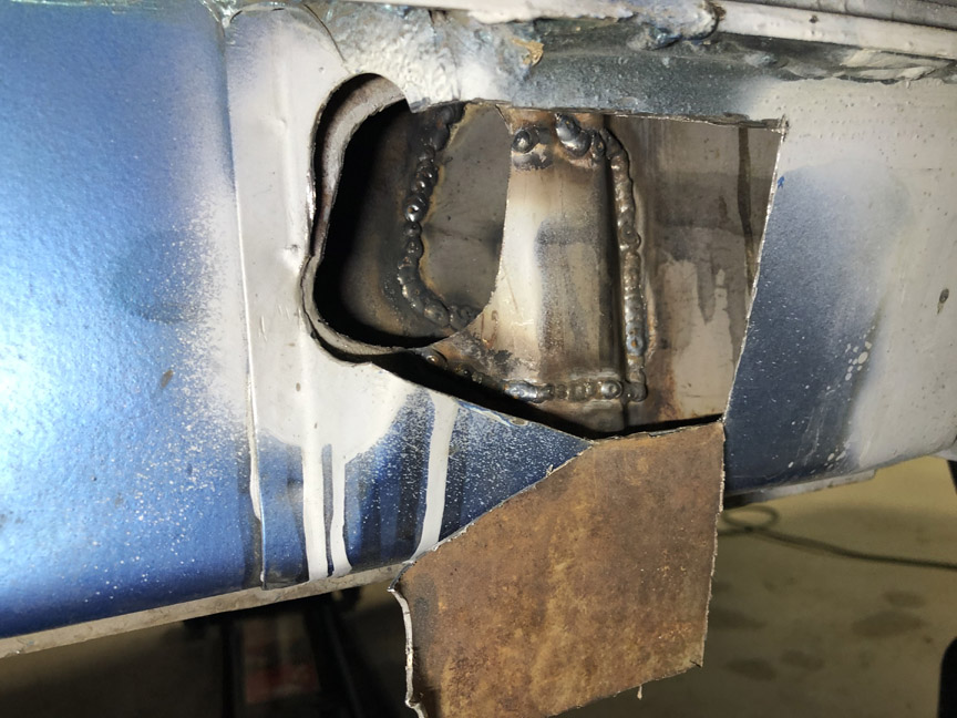
And the finish of the second layer patch: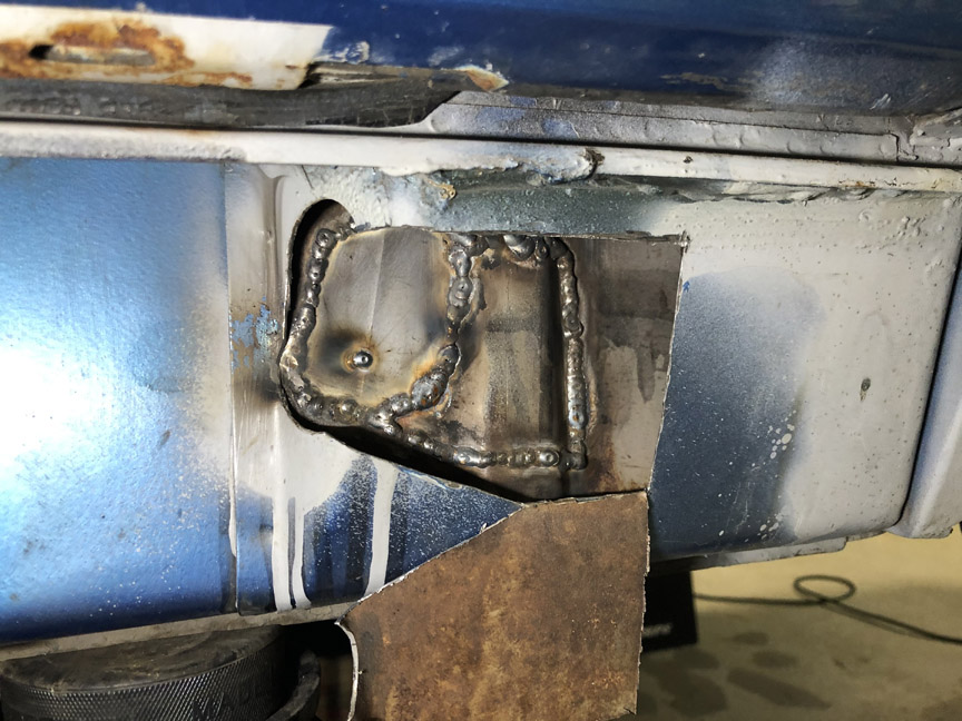
That's enough for tonight. I'll tackle the outer layer patches tomorrow.
Posted by: Superhawk996 Jul 14 2020, 07:50 AM

Like the screw as a handle. Still had to have been fun trying to place tacks in that tight space!
Maybe shoot some Eastwood Internal frame coating or something similar into that outer reinfocement to lock down the rust progression while access is easy?
Photo's like this always make me laugh. No such thing as rust free 914's. You just can't see it . . . . yet. It's always lurking inside these sorts of cavities.
Posted by: kroelofsen Jul 14 2020, 11:53 AM
 Nice work...!
Posted by: BillC Jul 14 2020, 12:35 PM
Nope, not much fun at all. My legs and neck were very sore and stiff after that was all done, just from the contortions needed to make the welds. But, I was trying hard to keep the holes as small as possible.
It wasn't shown, but I've been spraying rust-converter paint inside each layer right before I seal them up. I do have the Eastwood Internal Frame coating, which will be applied inside the heat tube and inside the longitudinal through the factory access holes inside the passenger compartment.
Someone here quipped a while ago that "rust free 914" just means the seller isn't charging for the rust.
 (
(  )
)
Posted by: bkrantz Jul 14 2020, 08:29 PM
Be fair! I am sure most 914s were free of rust for at least a few weeks after leaving the assembly line.
Posted by: BillC Jul 15 2020, 04:34 PM
Be fair! I am sure most 914s were free of rust for at least a few weeks after leaving the assembly line.
There's an old story out there on the internet, from a Porsche factory manager, where he said that at the end of the day, after all the lights, fans and other noises were turned off, he could actually hear the cars rusting on the production line.
Since I know everyone is just dying with anticipation to see the end of the "lovely holes" fix, here it is:
Yesterday, I welded in the outer layer patches. Didn't get anything else done since CINC-House had other plans.
Today, I ground the welds down and then primed the patch.
Once the epoxy primer dries, I'll hit it with some high-build primer, sand it smooth and the holes will be gone.
I also installed the new Tangerine Racing stainless steel fuel lines. While I was in the engine compartment, I found this stunning example of prime DAPO-ism:
Instead of proper rubber grommets, they sleeved the holes with aluminum flashing. They did put some thought and effort into this, shaping the aluminum to hold the hoses centered and also not fall out. Just too bad they didn't think to do it properly. SMH
Posted by: BillC Jul 17 2020, 04:52 PM
Time to do more work on the fuel system.
First, need to fit a new vinyl overflow tube to the gas tank (the old one was broken off too short). This was kind of a pain, since the tube has to stretch quite a bit to fit over the nipple. But, here's the result: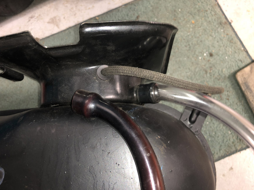
Next, is to mount the fuel pump and fuel filter. I'm mounting them up front, and need to make sure everything will fit and clear. I'm using a Tangerine Racing fuel pump mount. I decided to also make a mount for the metal fuel filter. Here's how I did it.
First, start with a strip of aluminum, 1" wide by 2.5" long and fold a "Z" bend in the middle: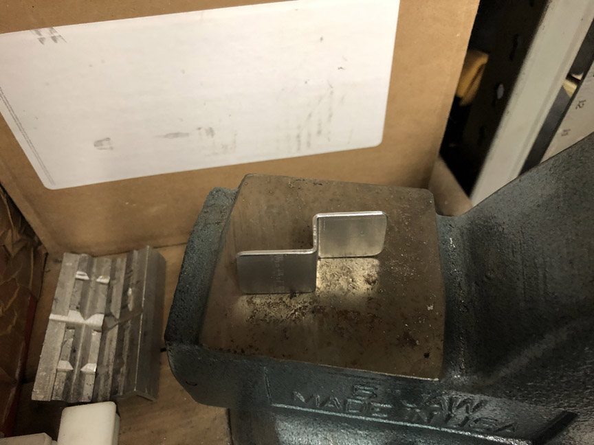
Then, shape one end over a socket: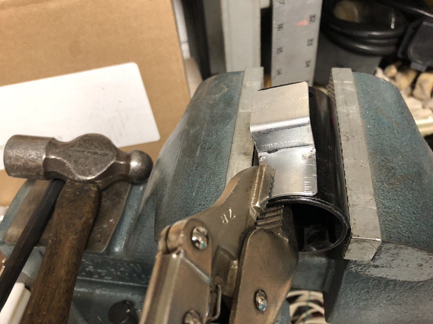
Here's the finished bracket: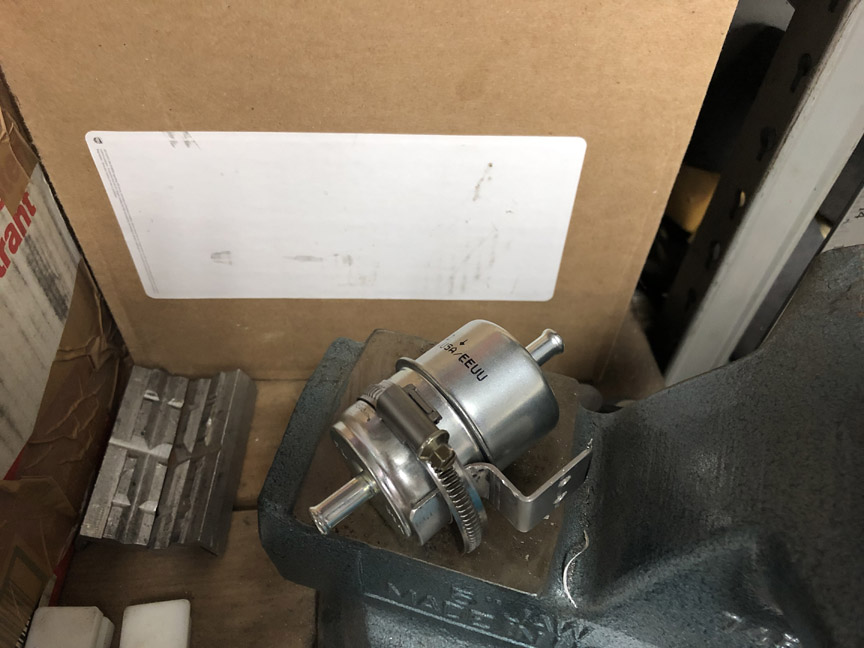
And, all the brackets mounted: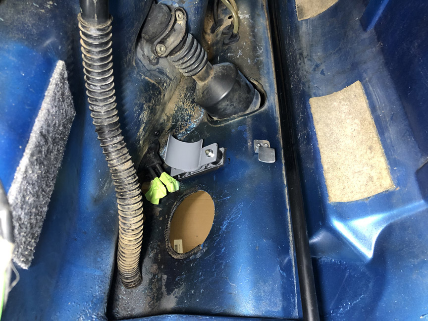
I'll install fuel lines and run wires tomorrow.
Posted by: Superhawk996 Jul 18 2020, 08:43 AM

Posted by: Cupomeat Jul 18 2020, 09:05 AM
Love this thread! Thankfully I've had my 914 for 33 yrs, but I have to admit that somedays i am fixing things that I did wrong when I was 17yrs old...
That makes me the DACO!
Posted by: barefoot Jul 18 2020, 02:13 PM
Next, is to mount the fuel pump and fuel filter. I'm mounting them up front, and need to make sure everything will fit and clear. I'm using a Tangerine Racing fuel pump mount. I decided to also make a mount for the metal fuel filter. Here's how I did it.
And, all the brackets mounted
[/quote]
I hope you won't have to remove the fuel tank next time a new filter is needed ??
Mine are just behind the opening in the front firewall where there's access (late years fuel pump mounting area)
Posted by: BillC Jul 18 2020, 06:27 PM
Love this thread!
Thanks! Sometimes I wonder if anyone's reading this or if I'm just wasting electrons.
I hope you won't have to remove the fuel tank next time a new filter is needed ??
Mine are just behind the opening in the front firewall where there's access (late years fuel pump mounting area)
Yes, the tank will need to come out for a filter or pump replacement. However, it does mean that there's no need to cut a big hole in the firewall. And, given the car's current "toy" status, the fresh new screen inside the tank and how long modern fuel filters tend to last, that will probably be the next owner's problem....
Posted by: BillC Jul 18 2020, 06:27 PM
Anyway, finally got the pump, filter and hoses installed. Also ran a pair of wires from the rear to the front to power the pump. Here's what it looks like, before the tank goes in: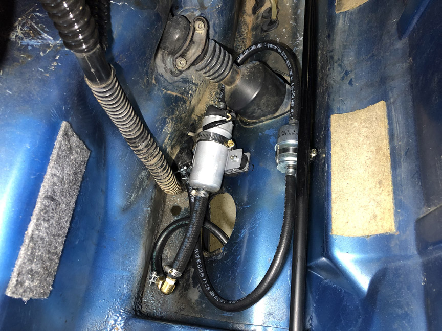
I ran the wires through the center tunnel, and drilled a hole in the bulkhead to connect to the pump. I fitted a grommet to protect the wires (can be seen in the above pic).
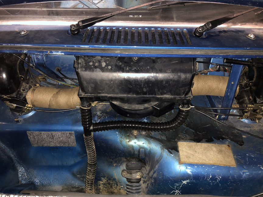
Since the snorkel tube was cracked open, I took advantage of the break to run the wires through it and up into the engine compartment.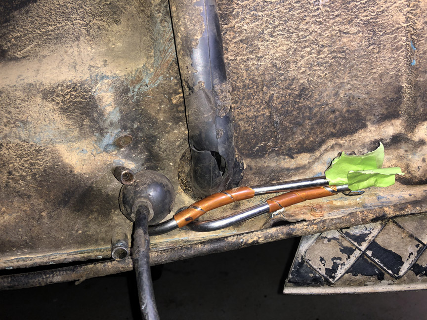
Once the pump wires were run, I decided to fix the snorkel. If you are very careful with CA glue, the factory rubber bits glue together nicely. A tip for accurately placing the glue is to put a drop on the tip of a small screwdriver and then use the screwdriver to spread the glue. And, work in small sections, starting at the ends of the crack and work towards the center.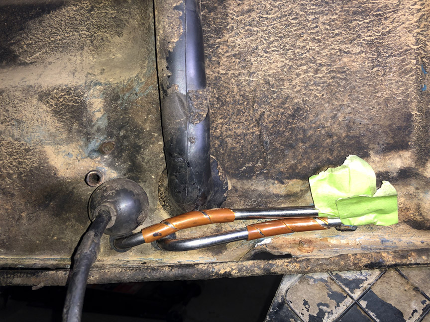
Almost as good as new.
Posted by: bkrantz Jul 18 2020, 08:33 PM
Love this thread!
Thanks! Sometimes I wonder if anyone's reading this or if I'm just wasting electrons.
I hope you won't have to remove the fuel tank next time a new filter is needed ??
Mine are just behind the opening in the front firewall where there's access (late years fuel pump mounting area)
Yes, the tank will need to come out for a filter or pump replacement. However, it does mean that there's no need to cut a big hole in the firewall. And, given the car's current "toy" status, the fresh new screen inside the tank and how long modern fuel filters tend to last, that will probably be the next owner's problem....
Don't worry--we are definitely reading.
Did you consider mounting the pump on the underside of the floor panel (above the steering rack)?
Posted by: BillC Jul 19 2020, 05:51 AM
Did you consider mounting the pump on the underside of the floor panel (above the steering rack)?
Yes, I did. Between the brake lines and the steering rack, there just wasn't enough room in that area to mount the pump with the TR pump mount and have sufficient clearance all around. I also thought about just mounting the pump directly to the sheet metal, but decided I really wanted it to be rubber mounted -- the pump is very loud without rubber isolators.
Posted by: BillC Jul 23 2020, 02:11 PM
So, the parts I've been waiting for finally arrived. With the new drain hoses for the fresh air box in hand, I was able to get the tank re-installed.
The drain hoses are held in by ring clips, which have quite a bit of force. I wasn't able to hold them open reliably and safely with any of my existing tools, so I modified a pair of pliers to work. First step was to take them apart, then to mill a slot in each half. The slot was offset from the center-line of the jaws so the clip would fit properly.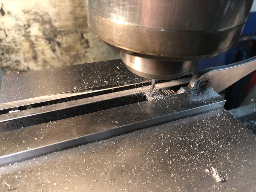
Here are the pliers reassembled and holding a ring clip. They work very nicely.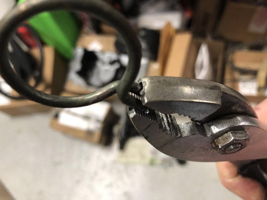
And, a shot with the tank installed and everything mounted back onto it.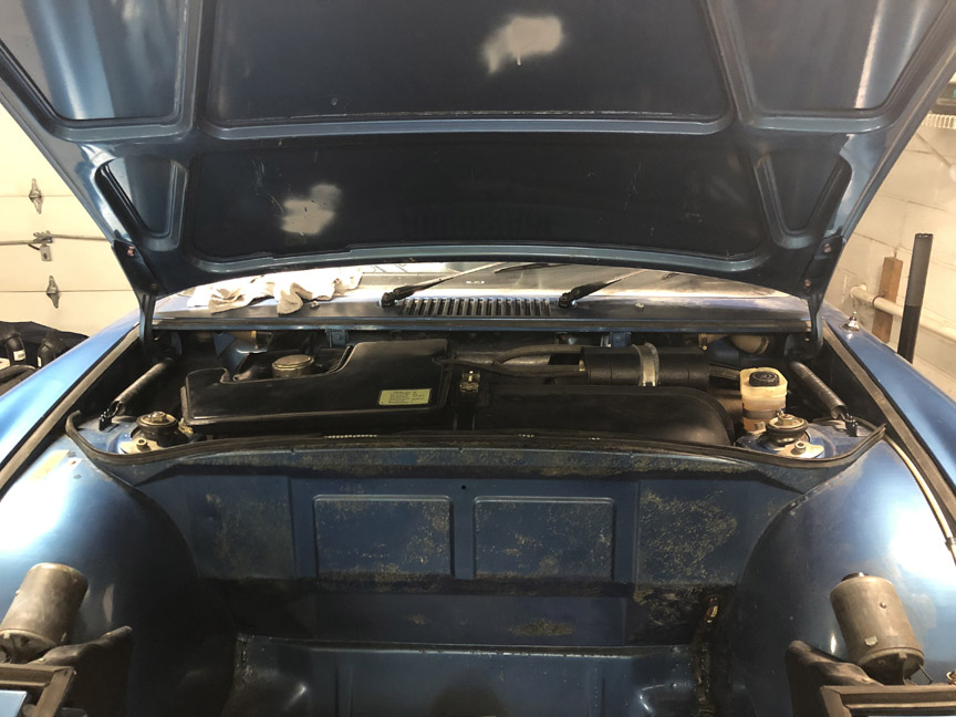
It looks a little high, but I made sure everything fits under the hood with clearance. I didn't bother with pics of the installation process, since it's a standard tank being installed in a more-or-less standard car. The only real annoyance was getting the rubber side pieces positioned properly, since it was rather finicky to get them at the right height.
Posted by: Superhawk996 Jul 23 2020, 02:33 PM
Here are the pliers reassembled and holding a ring clip. They work very nicely.

Posted by: BillC Jul 24 2020, 03:27 PM
Last night, I glued the perlon back on the front bulkhead and put the spare tire and cover back in place.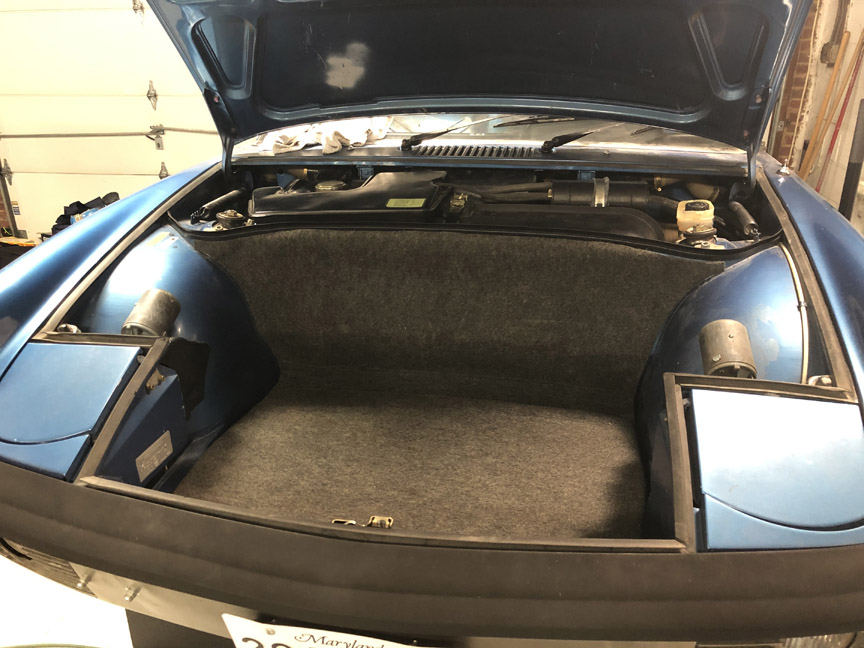
I would have ordered new perlon from 914Rubber, but they're on backorder. I'll replace it with a new one at some point, since there's a chunk cut out of this one below the spare tire cover.
Posted by: BillC Jul 26 2020, 10:38 AM
This is what the battery tray looked like: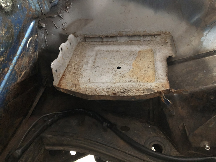
This is the result of old age, not prior-owner abuse, but it still needs to be fixed. So, out it comes.
I was really hoping to be able to keep the original tray support, but it was a little too rusty to keep using. So it came out too. Here's the result: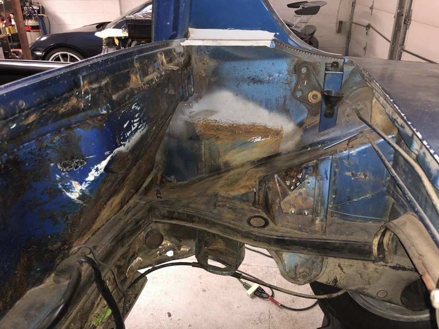
Next step is to clean up the remaining rust and paint it. Then, the new tray and support will be installed.
Posted by: Frankvw Jul 27 2020, 01:05 AM
good trick with adjusting these pliers !
Question, when you took out the battery tray, did you manage to do that damagefree for the other side ? (outerside of the car) ?
(in case someone wanted to replace his/her tray, could that be done without hurting the other side ?)
Posted by: BillC Jul 27 2020, 02:20 PM
good trick with adjusting these pliers !
Question, when you took out the battery tray, did you manage to do that damagefree for the other side ? (outerside of the car) ?
(in case someone wanted to replace his/her tray, could that be done without hurting the other side ?)
It's relatively easy to remove the tray without damaging the outer quarter panel or the inner panel (the one you can see in the pic). I did it by using a dremel tool and grinding through the spot welds inside the battery tray; although it is kinda slow and time consuming. If you're careful, you can get all the spot welds and not damage the car's sheet metal.
For re-installation, I will drill holes for plug welds to attach the tray support to the car and the tray to the tray support. I will probably also drill holes through the inside panel, for plug welds to the lip of the tray. However, I'm going to test and make sure I can get my welder nozzle in the space between the inner and outer panels before drilling the holes -- if it doesn't fit properly, I'll have to figure something else out.
If you want, I'll take more pictures of the installation process, to show the steps.
Posted by: Frankvw Jul 27 2020, 02:25 PM
"If you want, I'll take more pictures of the installation process, to show the steps."
That would be great, thank you very much and good luck !
Posted by: BillC Aug 9 2020, 06:32 PM
Well, it's been too long, but I finally had a chance to work on the car again today. I was able to remove most of the rust in the battery tray area, but the wall where the tray attaches was just too far gone. So, I cut out the rust, made a patch and welded it in.
Here's the hole: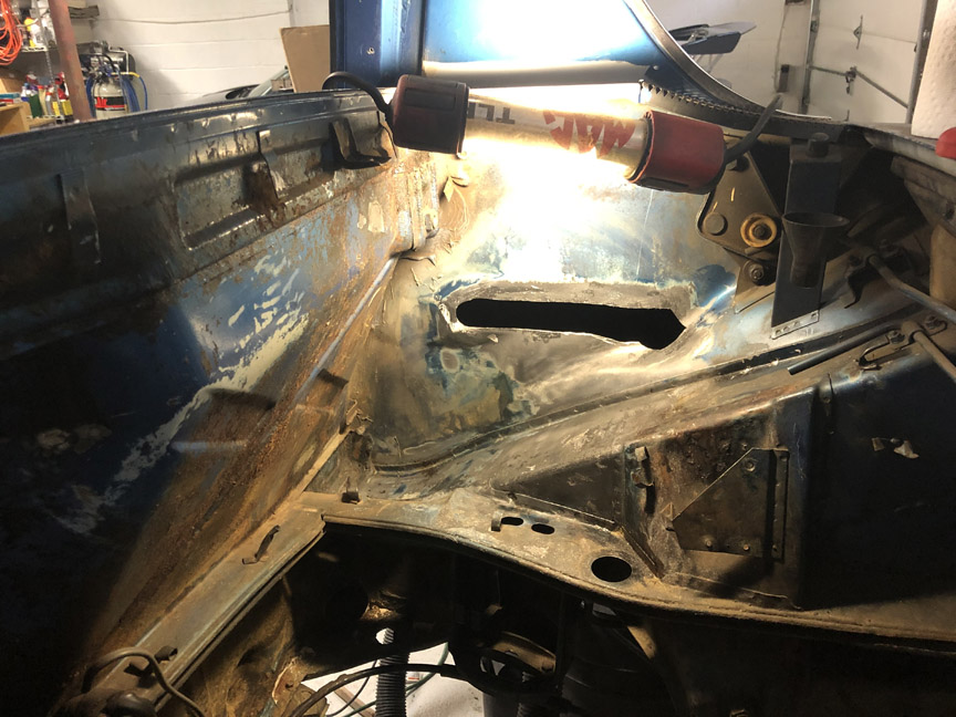
Here's the patch next to the cut-out piece: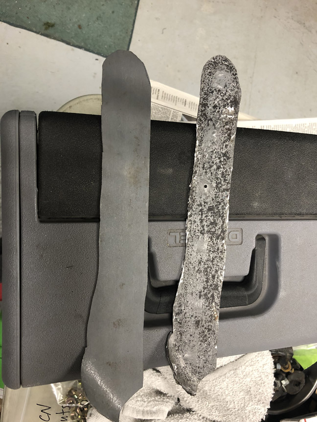
And here's the patch welded in, with some of the grinding done.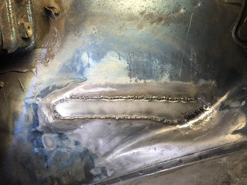
Still need to finish grinding and then paint, before I can install the battery tray.
Posted by: porschetub Aug 9 2020, 09:14 PM
you have great metal fab skills,well done but expect to find other BS from the PO as after many years I'am still finding ……..
Posted by: BillC Aug 23 2020, 06:02 PM
Didn't plan on it taking so long for this next update, but we've gone back to work full time and it's been pretty busy. Plus, family and life have a tendency to get in the way. But anyway, I did make some progress.
I finished grinding and primed the inner quarter, where the battery tray goes: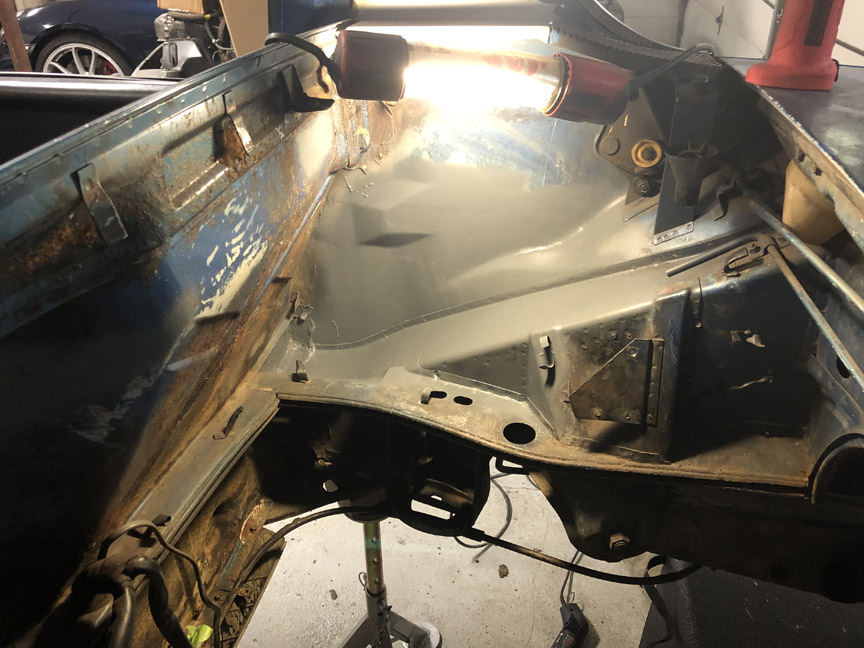
Then I welded a nut into the stand and then pre-drilled it, in preparation for welding: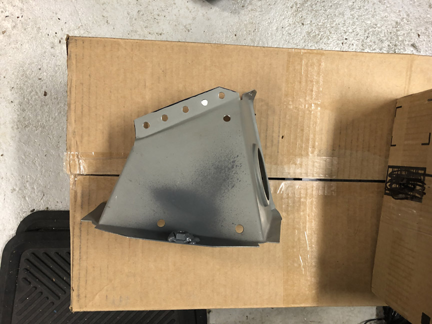
I then welded the stand in place, using the tray as a guide. I also pre-drilled the inner quarter for plug welding the outside edge of the tray.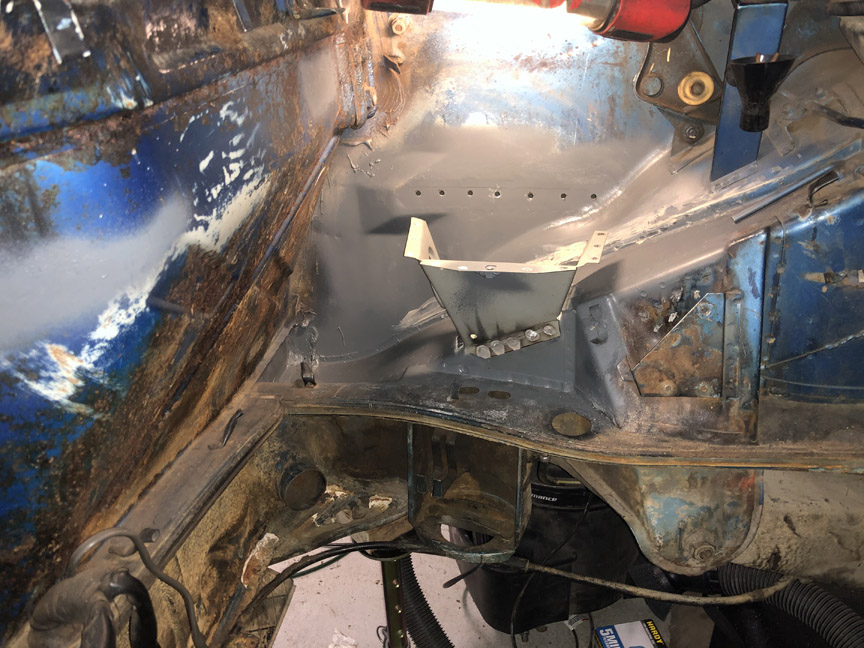
This is what it looks like inside the quarter panel. It's tight in there, but I can get the mig welder nozzle in and make plug welds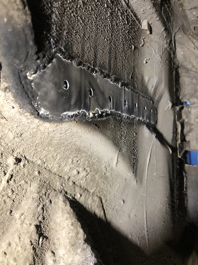
Because it will be such a pain to paint the underside of the tray and inside the stand after the tray is welded in, I pre-painted the tray and inside the stand.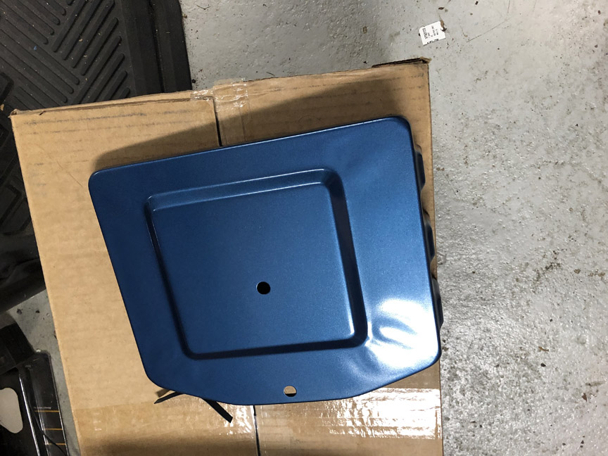
I also drilled the holes for mounting the ECU: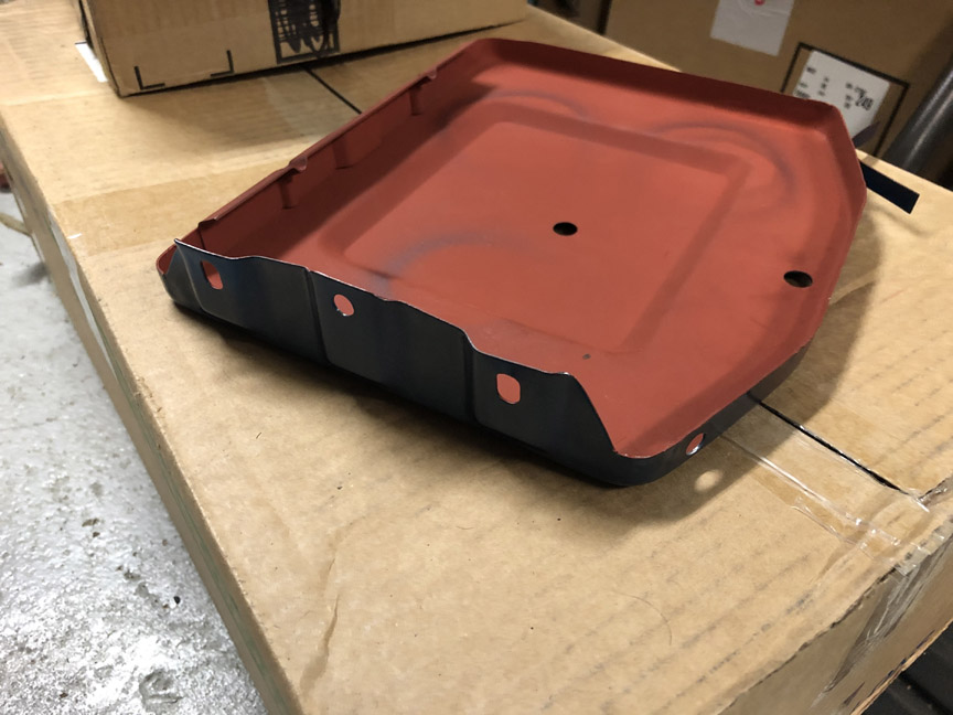
Finally, I welded in the tray.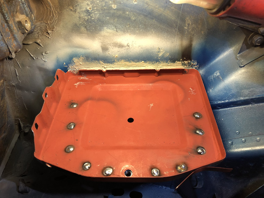
Here's the inside of the quarter panel, after welding and undercoating.
Posted by: BillC Oct 12 2020, 04:01 PM
Well, it's been waaaay too long since I made any progress on the car. Don't really have much of an excuse, except life gets in the way sometimes.
Anyway, I finished and painted the battery tray. I also cleaned up and painted the little metal pieces on either side of the decklid and reinstalled the rear window and trim. Still have a ways to go, but I feel better putting some pieces back on the car.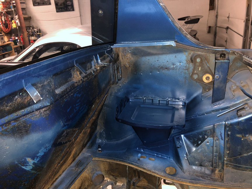
Posted by: Tdskip Oct 13 2020, 09:02 AM
Nice going, and thanks for the updates!
Posted by: BillC Oct 22 2020, 02:22 PM
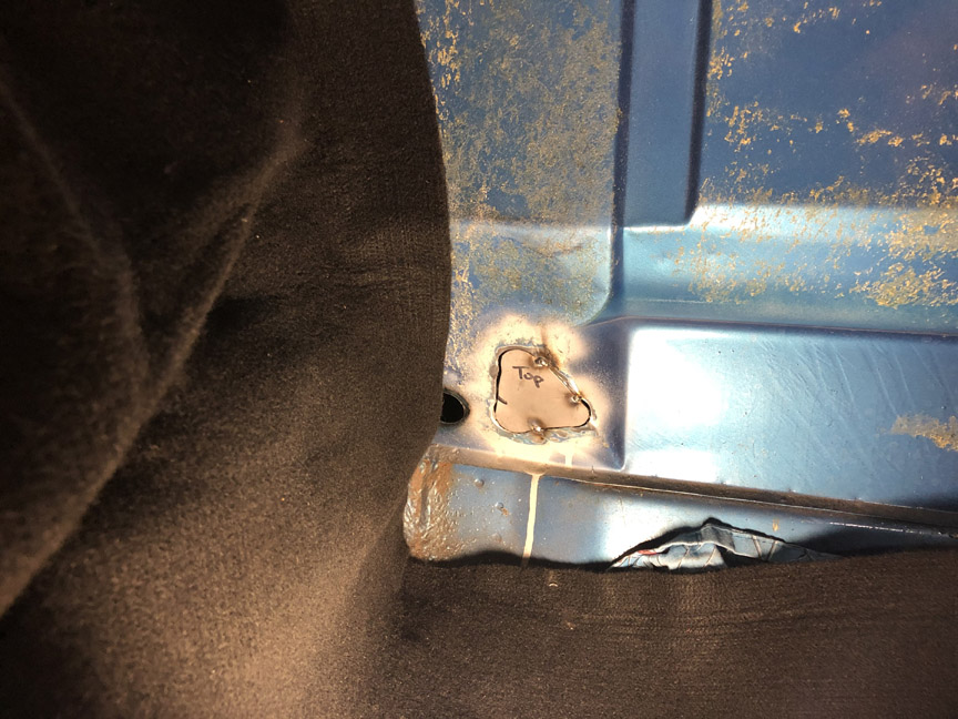
It's finally time to take on the last "DAPO" thing I've found (so far) on the body -- the hole in the passenger-side latch panel.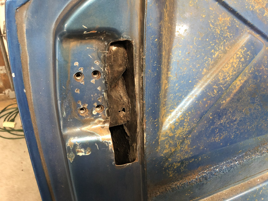
Sorry, I forgot to take a picture of the rust holes inside the DAPO-hole all welded up. It's done, but you'll just have to trust me that I did it. 
I was able to buy a patch piece cut out of a donor car. Here's a pic of it trimmed to fit.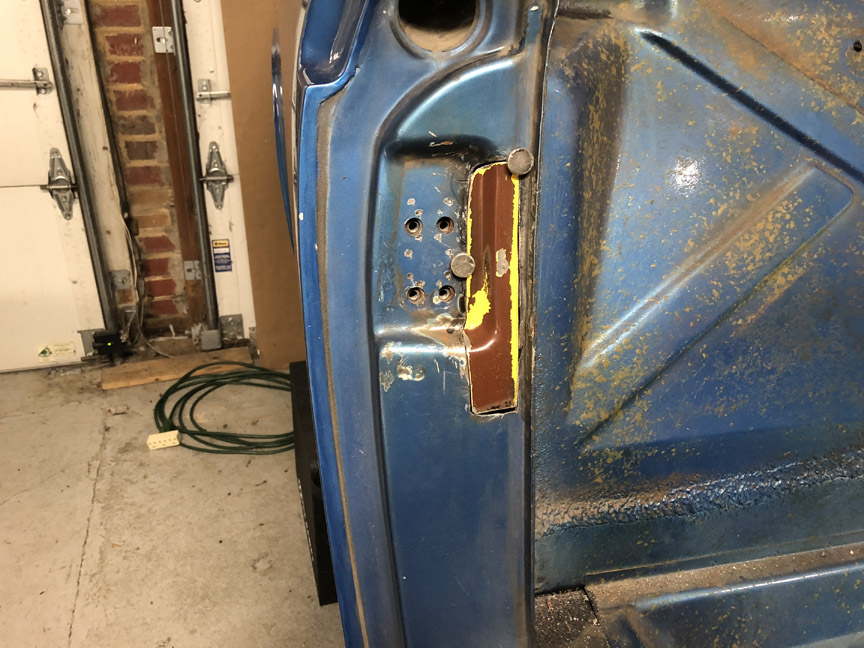
I bead-blasted the patch and painted the backside to protect it. Then, I cleaned the metal around the hole and tacked the patch in place.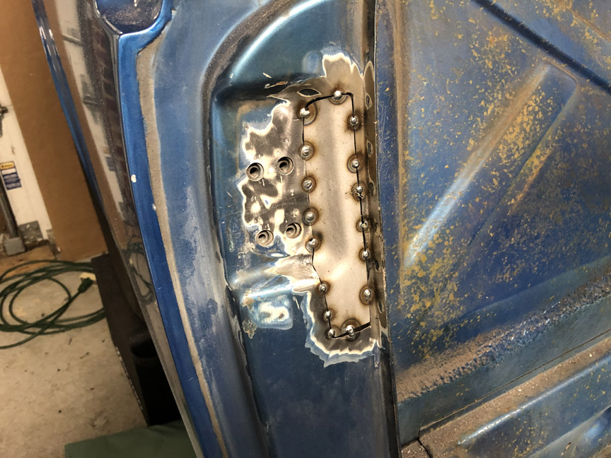
In the next update (whenever that might be), I'll show the second half of patching the hole -- welding, grinding, filling and painting.
Posted by: BillC Nov 2 2020, 03:32 PM
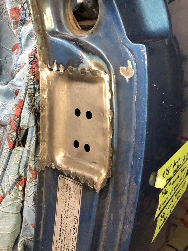
I was able to spend some time with the car this weekend, and I finished the passenger-side latch panel.
Here's the patch fully welded in: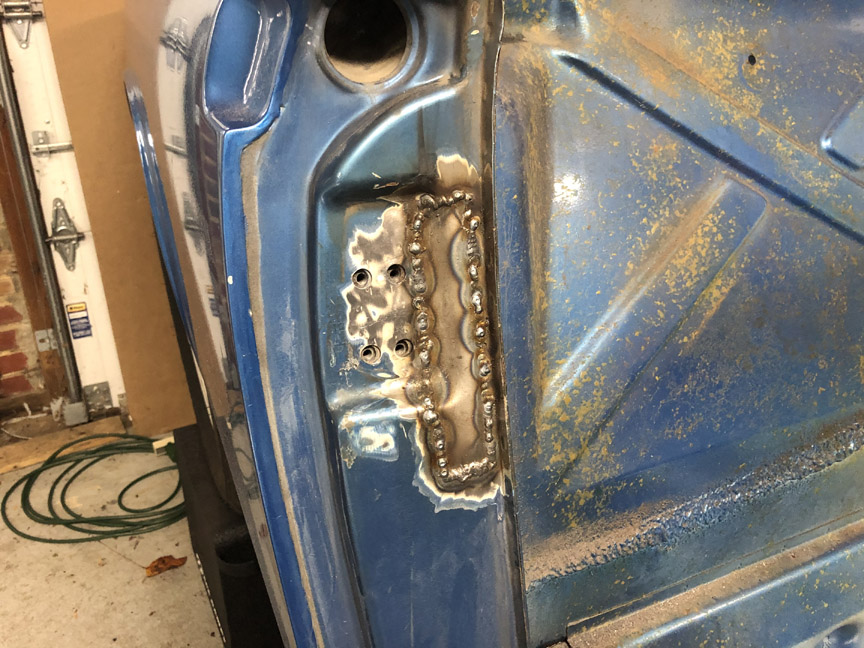
Here's the patch ground down: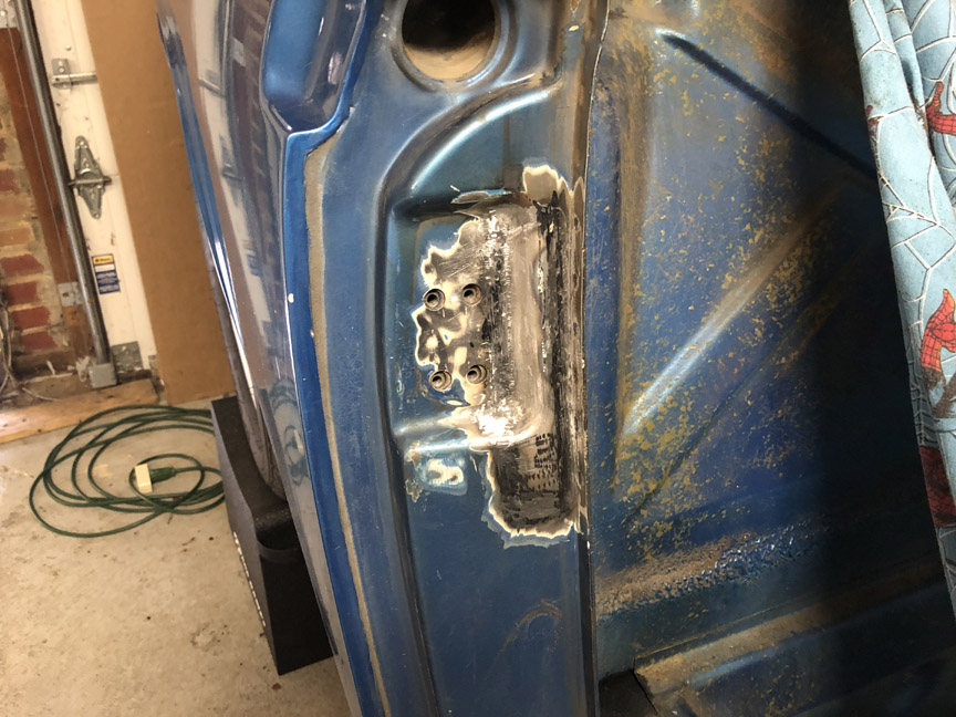
Here's the patch filled, primed and painted: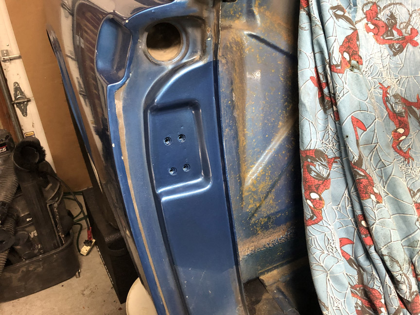
Not the prettiest job, but it will work until I have a chance to do a full restoration some time in the distant future.
Posted by: Cairo94507 Nov 2 2020, 04:42 PM
Very very nice work.
Posted by: BillC Nov 11 2020, 04:17 PM
I took advantage of the federal holiday to spend a little more quality time with the car today. Today's task was to fix the six bolt holes (3 per side) used to attach the bottom side of the rocker panels. I was hoping that all I would need to do was drill them out with a left-handed bit and everything would be good, but nope, the DAPO had other ideas.
Every single hole had a broken bolt stuck in it, and every single broken bolt had a hole drilled off-center through it. Like this: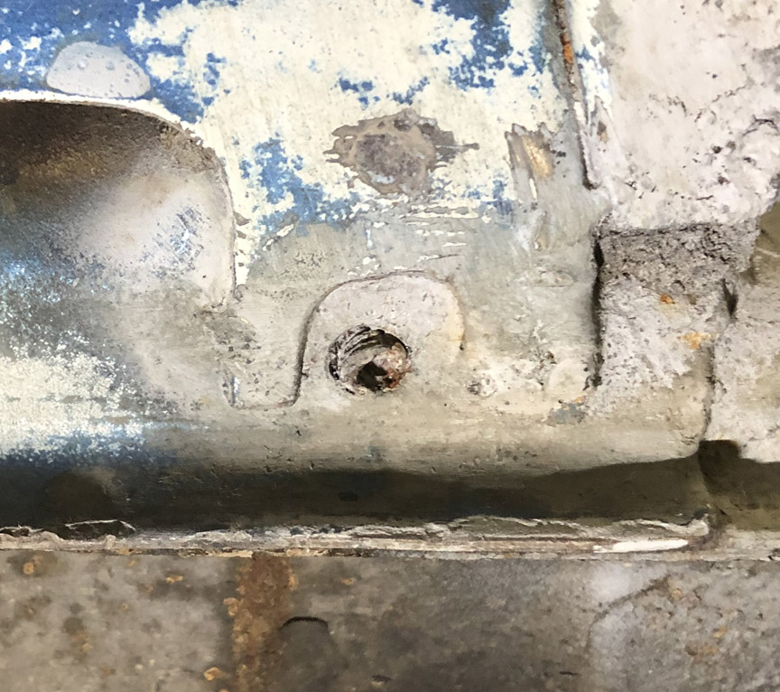
You'd think after boogering up one or two holes, the DAPO would take a step back and try to get better instructions and/or tools for this job (or an f'ing clue), but nope, they charged forward and screwed up all the holes (only one shown for brevity).
For five of the holes, I was able to use my dremel tool with a tiny carbide bit to grind out the remnants of the bolt. Then, for each hole, I drilled the hole oversize, tapped it and installed a helicoil.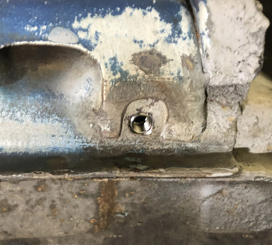
However, one of the DAPO-holes was so far off-center, I had no choice but to grind the hole oversize and weld it up. I then drilled, tapped and installed a helicoil in this hole so it would be consistent with the others.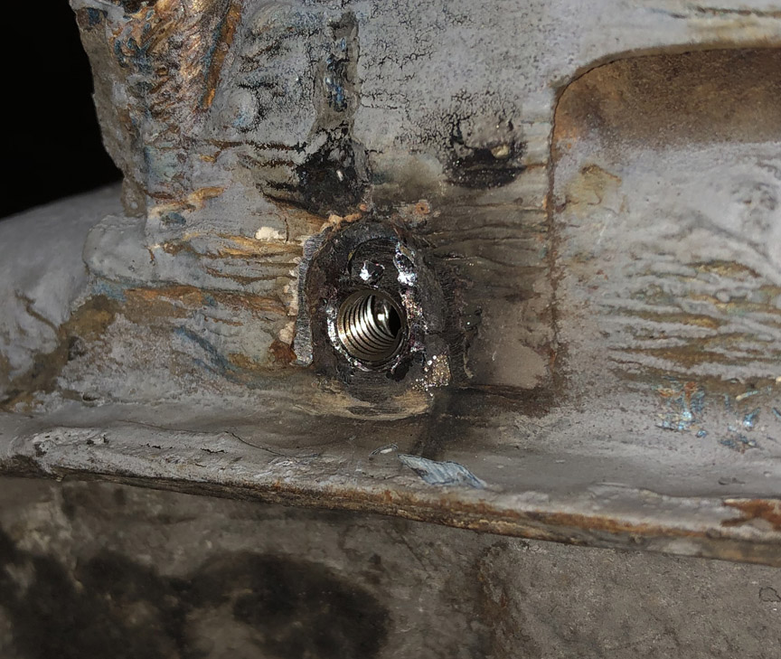
Posted by: Morph914 Nov 11 2020, 08:10 PM
Your thread makes me realize how fortunate I was to obtain a clean dry car with no dapo issues to deal with.
Thank you for posting your progress, keep up the good work!
Cheers,
John
Posted by: BillC Nov 28 2020, 10:07 AM
I had some time yesterday to work on the car, so I decided to take care of prepping the passenger-side door for a mirror.
All 914s came from the factory with nut plates for mirror mounts welded inside both sides. However, normally only the driver's side was drilled out for the mirror. A factory passenger-side mirror was a rare option; it seems like most original owners that wanted two side mirrors just installed a pair of aftermarket mirrors. But I want original-style mirrors.
All I could find for instructions was to just "drill out" the sheet metal skin so you could screw the mirror to the nut plate. However, there are two issues with that simple guidance: First, you have to locate the holes from the inside to the outside; and Second, with my luck, I'd end up going too deep and drilling the threads out of the nut plate, ruining it as a mounting site.
So, here's what I did:
First, I unbolted the door and laid it on towels on a workbench. Then, I located the nut plate inside the door -- it's located just outboard of the post between the sliding window and the fixed triangular window. Here's a pic: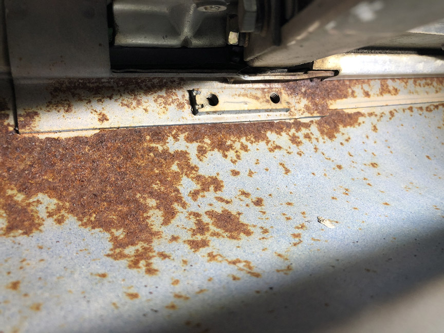
Then, I drilled pilot holes from the inside out. This was the only way I could guarantee getting the outside holes in the right place. It's very tight inside the door, especially with the window frame still installed, so I pulled out every right-angle drill attachment I own -- both of them -- and was able to cobble together a way to drill the pilot holes with a stubby 3/32" bit. Here's what the tool looked like: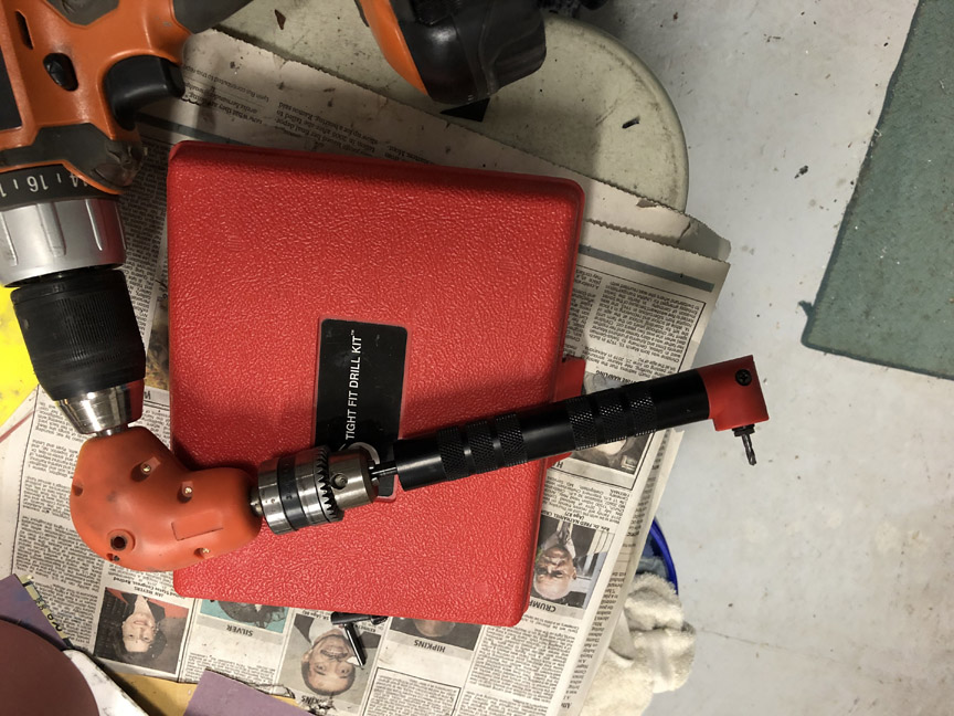
And here's what the pilot holes looked like on the outside: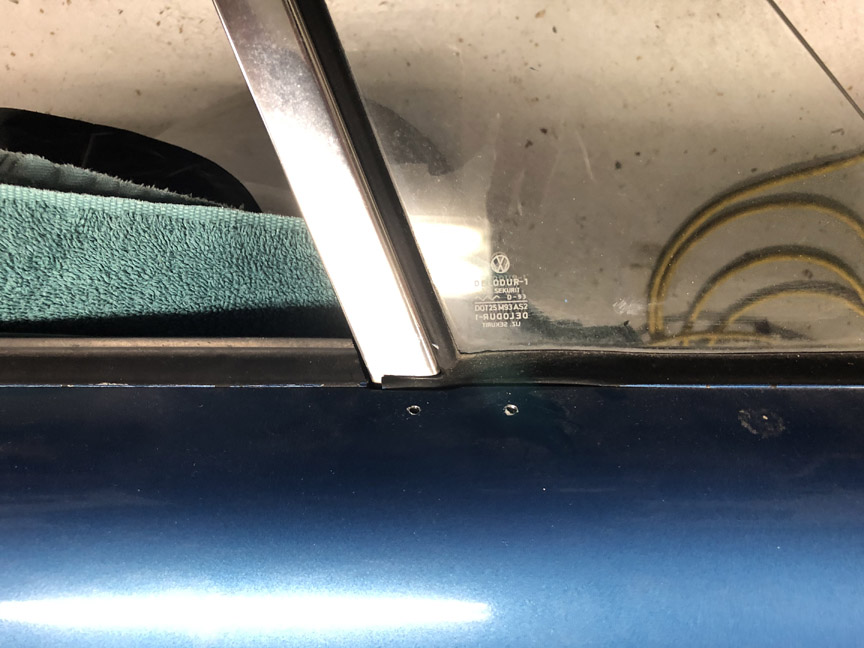
Then, I took my dremel tool with a small pear-shaped cutter bit and carefully ground the holes out to full size. This was actually the most time-consuming part of the project, but it let me make sure the holes were centered on the threads in the nut plate. After grinding, I chased the threads with a 6-1.0 tap and then touched up the paint. Here's the final result: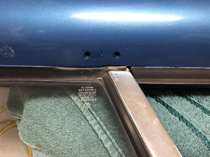
Then, after I was finished with the mirror holes, I went back and painted all the rusty areas inside the door with rust-converter. It's not ideal, but it should stop the door from rusting inside-out before the car can get a full restoration.
Posted by: StarBear Nov 28 2020, 10:45 AM
Very very nice work.
Posted by: bkrantz Nov 28 2020, 08:58 PM
Your thread makes me realize how fortunate I was to obtain a clean dry car with no dapo issues to deal with.
Thank you for posting your progress, keep up the good work!
Cheers,
John
What fun would that be?

Posted by: Superhawk996 Nov 29 2020, 10:25 AM
Then, after I was finished with the mirror holes, I went back and painted all the rusty areas inside the door with rust-converter. It's not ideal, but it should stop the door from rusting inside-out before the car can get a full restoration.
Good job. Love these sorts of pictures to reinforce there is no such animal as a rust free 914 regardless of how it looks on the outside! Keep going - your car is coming along nicely.
Posted by: BillC Nov 29 2020, 04:21 PM
Now it's time to tackle a common 914 problem (woohoo! . . . err, I think . . .) -- the jack points. Mine actually looked pretty good externally, but I discovered that both were packed full of sand and rust. Here's what the driver's side looked like after getting the sand out. Those little "lines" next to the vent hole are actually rust perforations, not scratches.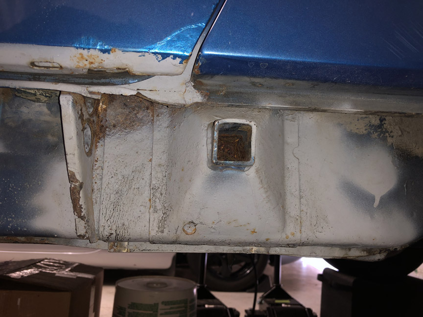
The passenger side was actually in worse shape than the driver's side, so that's where I started. Here's what the passenger side looked like after I took some tin snips to it: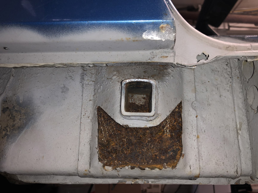
Pretty nasty inside.
At this point, there really isn't much choice except to replace (at a minimum) the jackpoint reinforcements. When I've read other people's projects, they usually chop off a good-sized chunk of the quarter panel behind the door opening. While this makes access to the top of the reinforcement much easier, it requires a lot of work to fix the quarter afterward.
I decided to try a different approach. I bought one of those little belt sanders you see on various car restoration shows.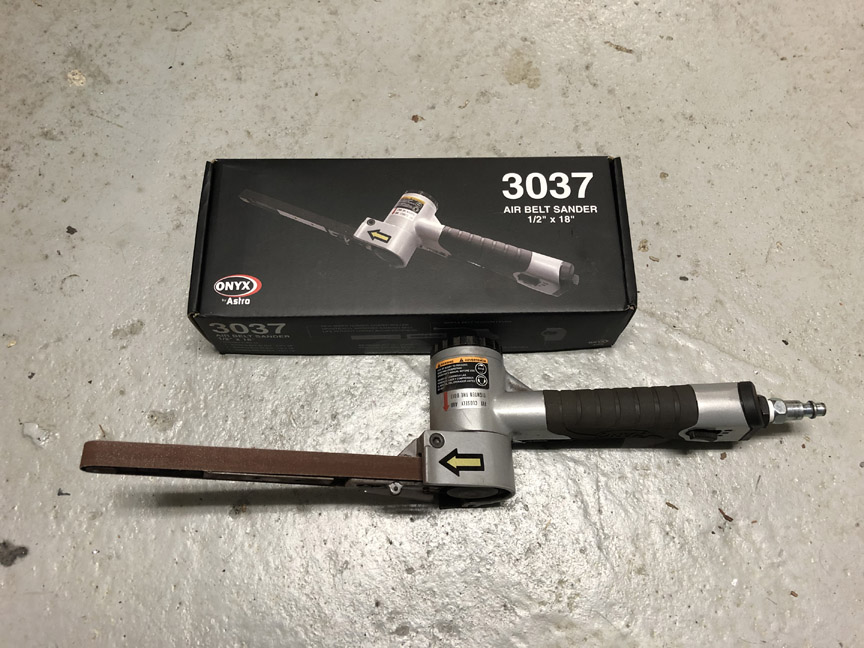
This thing works great! I'm astounded, I wish I had bought one many years ago. The 36 grit belt just zipped through the sheet metal, making it very easy to remove the spot welds on the bottom and the sides. The plan is to reach down from above (inside the quarter panel) to remove the top of the reinforcement.
I got about 80% through the removal process today -- the bottom and both sides are gone. The top part will have to wait for later, since I'm out of belts. The sander only came with one 36 grit belt, which lasted through taking off about half the reinforcement. The other belts that came with the kit didn't last very long, since they were finer grit. So, now I have to wait for a new order of belts to come; they should be here in time for next weekend.
This is what the piece looks like now: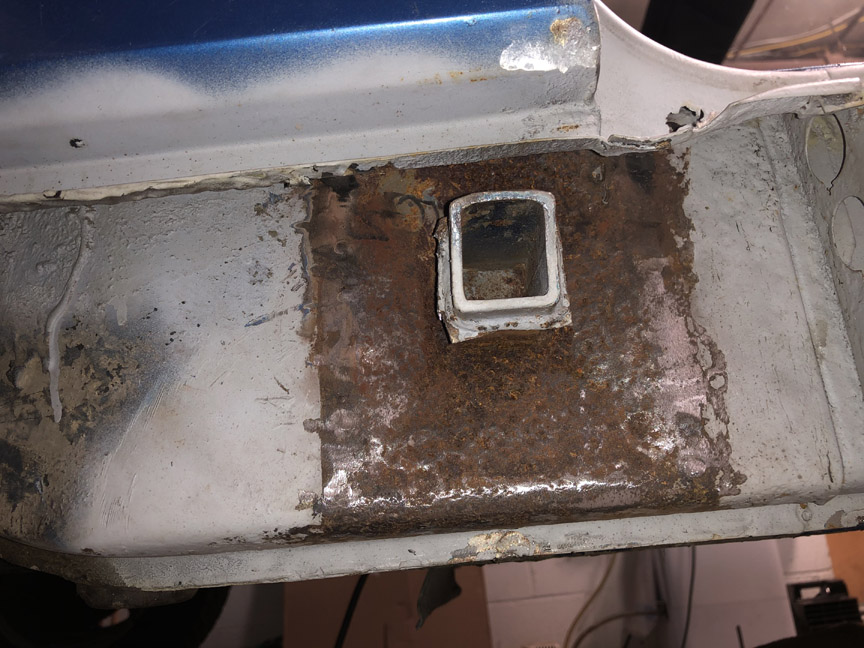
Haven't quite decided what to do about the inner sheet metal. There are no penetrations and the jack post is solid, but the sheet metal is rather thin in spots. I'd like to replace the sheet metal, but replacement stampings are rather pricey, especially for the small pieces I'd need from it. On the other hand, McMaster sells galvanneal sheet -- I can get a 2'x2' panel for less than half of one of the pre-formed parts, and have plenty left over. I guess we'll see once I get the rest of the old reinforcement out.
Posted by: Cairo94507 Nov 29 2020, 04:43 PM
Chasing the rust is a very very slippery slope. I began drinking when we were cutting out rust and replacing panels. I did not think I was going to survive that seemingly never-ending trauma.
In reality, looking back, dealing with the rust really was not that bad on my car. It mostly had bad body repair work from when these cars were a dime a dozen (and in VA) when no one took the time to do it correctly.
Fortunately, I had Kent Simmons (Auto Art Customs,Torrance, CA) on the job and he was 1000% up to the task. I have never regretted meeting and getting to know Kent. All I can say is if you have rust, not even bad rust, find someone who knows what they are doing so that rust issue, even after rust repairs, doesn't keep haunting you in all sorts of different ways.
Posted by: BillC Dec 5 2020, 05:07 PM
So, the new sander belts came in and I got back to work on the car this morning.
Here's what the remains of the jackpoint reinforcement looked like from inside the quarter panel: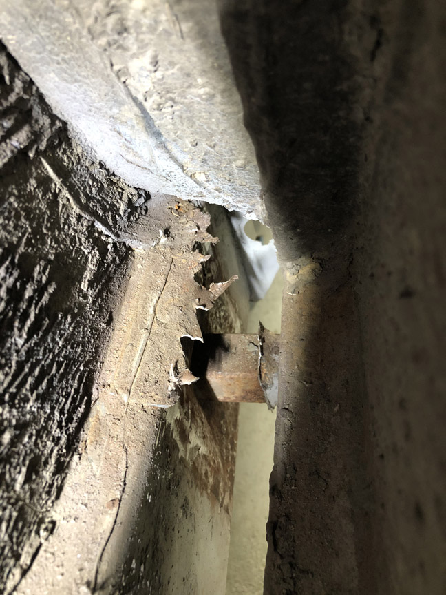
About a half-hour later, this is what that space looked like: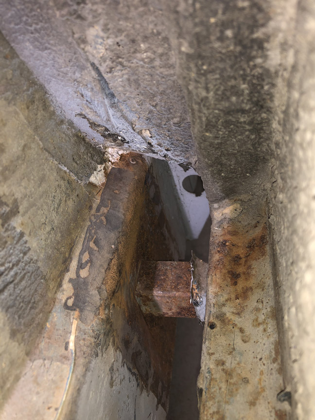
I am really liking this little belt sander. However, the generic 36-grit belts were disappointing -- the grit was caked on so thick, most of it cracked off pretty quickly. Fortunately, I also ordered some 3m cubitron 60+ grit belts that did a great job on the old sheet metal and rust.
Once I got the rest of the old reinforcement out, including cleaning the remnants off the jack post, I tried dry-fitting the new piece. I was pleasantly surprised to find that I can get the panel in place with just some wiggling; I was afraid I'd have to cut it in half, but no need.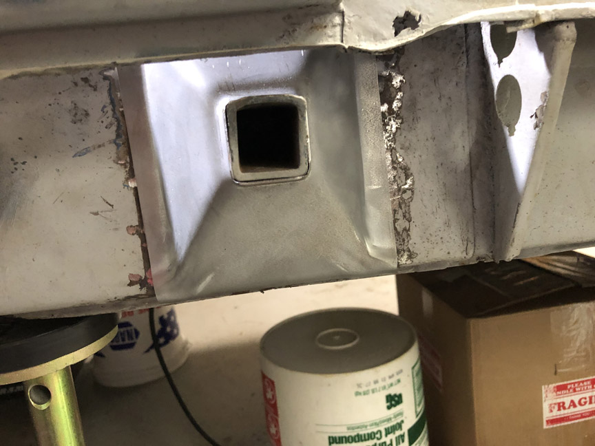
After that, I soaked the whole area down with Ospho. The plan is to use some Eastwood internal-chassis paint inside that area once everything is welded back in place.
Also, since I had the welder out, I decided to weld up the hole in the sheet metal under the door opening. You can see the hole in the above pics.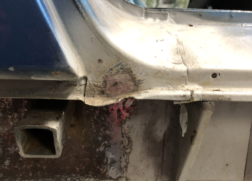
With any luck, I'll be be able to weld the reinforcement in place tomorrow.
Posted by: BillC Dec 6 2020, 12:13 PM
And . . . done!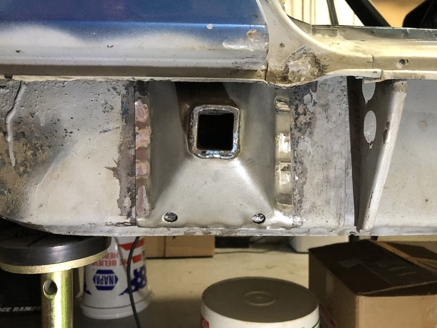
It even works!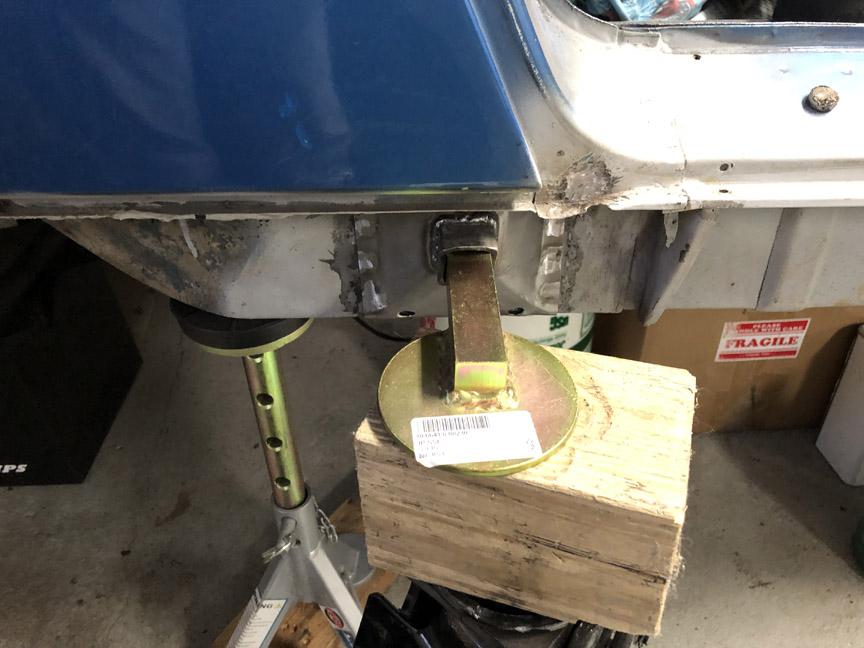
I need to finish cleaning up and painting this side, then it's on to the other side (joy. )
Posted by: BillC Dec 20 2020, 05:00 PM
And, now for the moment you've all have been waiting for!
Okay, well, maybe not all of you. Errr, well, maybe not any of you.... But it's the moment I've been waiting for, for far too long -- time to reinstall the passenger door!
It took a while to clean up the rust and old primer on the sill. It was all sanded down, treated with Ospho, re-primed and repainted. Here's what it looked like, just waiting for the door:
One little trick I figured out a long time ago, on a project far far away, is using studs to help with bolting on the hinges. Put one stud in the body plate for each hinge (one top and one bottom). This makes it much easier to line up and install the first two bolts. Once they're in, unscrew the stud and install the last bolt. Here's the idea: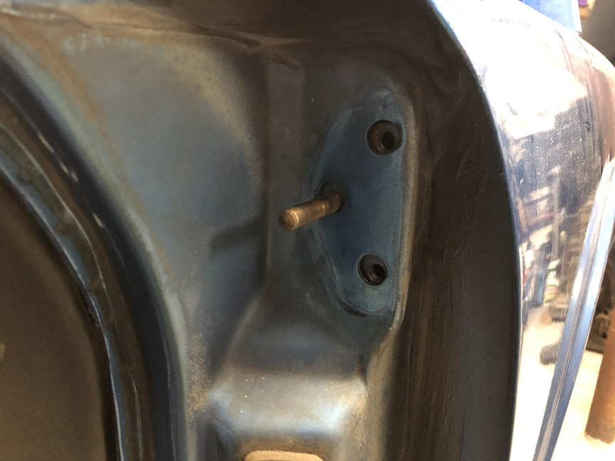
The doors mount with 8-1.25mm bolts, which are the same size as the exhaust studs. So, most of you probably already have a few lying around somewhere.
And, now the moment .... yeah, you know what's coming. The door installed!
This was a two-person job. I held the door in place, while my oldest son (who's home from grad school) installed the bolts. Then, he helped me adjust the door. It's lined up much better than when it arrived.
While I was at it, I also installed the passenger-side mirror. It's just a normal driver-side mirror, flipped over. Someday I may get a piece of convex mirror glass for it, but for now it'll work, and it just looks so much better than those aftermarket mirrors that were on my previous 914.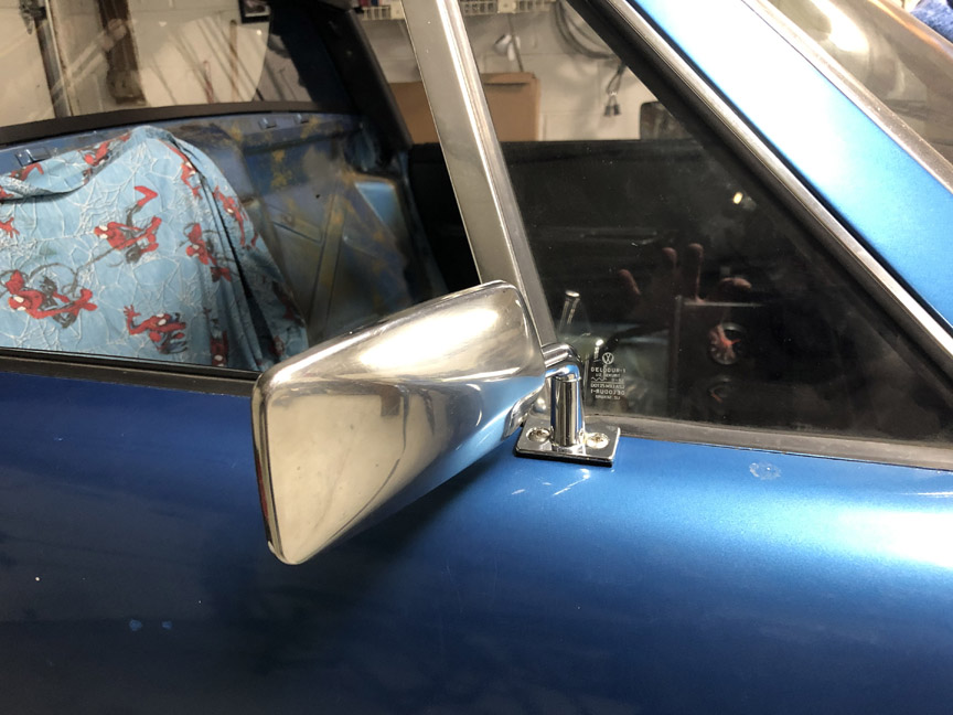
Posted by: AZBanks Dec 20 2020, 07:01 PM
Great work. Looks really good.
Posted by: bkrantz Dec 20 2020, 09:16 PM
Looks great.
And I agree: grad school sons are sometimes helpful.
Posted by: PanelBilly Dec 21 2020, 12:01 AM
Reading this makes me want to build another car. For now, I'll just watch from afar and admire your workmanship
Posted by: Superhawk996 Dec 21 2020, 09:01 AM
And . . . done!
No getting off that easy.
Do tell . . . . How did you weld the top? I'm assuming MIG with blind point & shoot approach? I've got a similar situation but will need to TIG. I'm really debating about removing the top 1/2 of the pyramid. I want full fresh metal in there but I think it's going to be almost impossible to weld the top. Having said that the welds along bottom and side would be more than enough to provide a functional support. Maybe just seam seal the top and be done with it.
Posted by: BillC Dec 21 2020, 09:32 AM
And I agree: grad school sons are sometimes helpful.
Yup, especially when they figure out how to pay for grad school on their own! In this case, he has a research assistant position that includes tuition and pays a stipend that covers room and board.
And . . . done!
No getting off that easy.
Do tell . . . . How did you weld the top? I'm assuming MIG with blind point & shoot approach? I've got a similar situation but will need to TIG. I'm really debating about removing the top 1/2 of the pyramid. I want full fresh metal in there but I think it's going to be almost impossible to weld the top. Having said that the welds along bottom and side would be more than enough to provide a functional support. Maybe just seam seal the top and be done with it.
As you guessed, I used a MIG welder. I pre-drilled all the rosette holes, then one-at-a-time, positioned the MIG gun over each hole and filled in the spot. I used the goggles from my acetylene torch, since I couldn't get my head in position to see while wearing the welding helmet -- it was a little bright, but much better than no protection at all. I did the top after doing the sides and bottom, so I didn't have to worry about the piece moving while welding.
Rather than just seam-sealing the top of your pyramid, maybe you can TIG the sides and bottom and then MIG weld the top like I did. Ugly welds hidden where no one can see should be better than no welds at all.
Posted by: Cairo94507 Dec 21 2020, 10:12 AM
Bill, @http://www.914world.com/bbs2/index.php?showuser=18667 , great job. So nice to see that door fitting properly and you are 100% right about the stock mirrors- they fit the car perfectly. I too wish I had a convex mirror on my passenger side mirror. Great Job.
Posted by: barefoot Dec 22 2020, 12:31 PM
And . . . done!
No getting off that easy.
Do tell . . . . How did you weld the top? I'm assuming MIG with blind point & shoot approach? I've got a similar situation but will need to TIG. I'm really debating about removing the top 1/2 of the pyramid. I want full fresh metal in there but I think it's going to be almost impossible to weld the top. Having said that the welds along bottom and side would be more than enough to provide a functional support. Maybe just seam seal the top and be done with it.
Don't need the top welds, for shear, all other welds have enough to handle this and in bending, all the bending loads on the top half are trying to push the gasset into the longs anyway, no tensile loads on those welds.

Posted by: bbrock Dec 22 2020, 02:29 PM
Just getting caught up on your thread. Fantastic work. The stud for hanging doors is a great tip!!! I lost count of the number of times I mounted my doors solo and could have really benefited from that bit of wisdom
Posted by: BillC Jan 10 2021, 11:43 AM
It may look like not much has happened since the last update, but most of that time was waiting for two little rubber bumpers. First place was back-ordered, but didn't bother to tell me before they shipped the rest of the order, which ended up taking nearly three weeks to be delivered (thanks again, usps. ). I then asked if anyone on this forum had a pair and finally found a pair , but now that shipment is lost in usps hell. So, ended up getting a pair from Stoddard, which was the same price as the original vendor.
So, this is what the decklid looked like when I removed it from the car. The PO had primed a lot of area, trying to minimize the spread of rust, but didn't actually do any rust removal.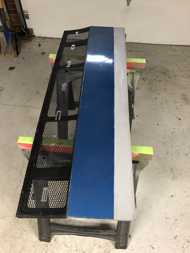
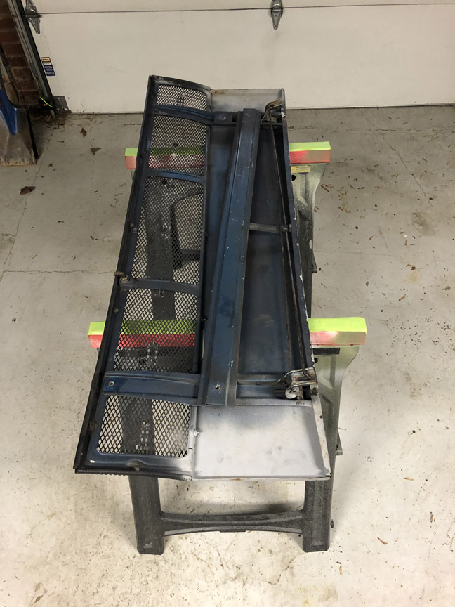
I took the grill and springs off, removed the extra primer, cleaned up the drip tray and repainted the decklid. Here's what it looks like back on the car: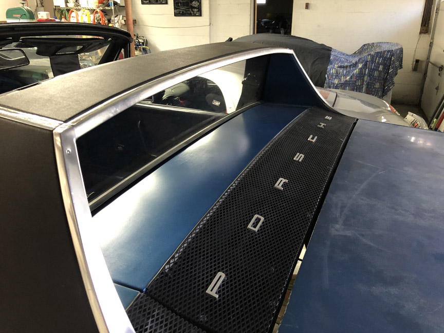
I thought I had taken a few pics after it was all painted and reassembled, but I guess I didn't (sorry).
While it was apart, I decided to add a third brake light. Someone on a local forum sent me a string of LED lights. Thanks, Matt! Here's what the new light looks like: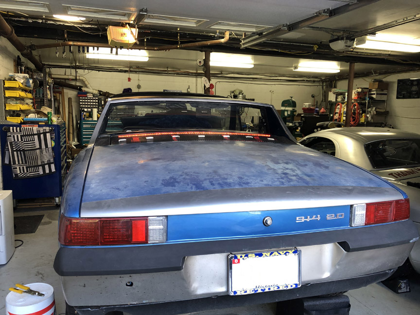
I will end up wiring it to the brake circuit, so it will light with the regular brake lights (already replaced with a set of Spokewerks LED tail lights).
And, in case anyone was wondering, here's what one of those long-delayed bumpers looks like installed: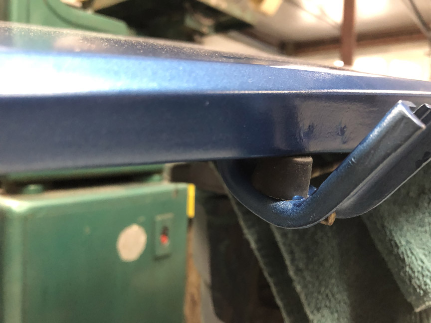
Posted by: pete000 Jan 10 2021, 03:25 PM
Just remember that is wasn't all that long ago these cars were considered cheap junk and people butchered them up on a regular basis...
Posted by: BillC Jan 17 2021, 02:16 PM
Time to take on the last rusty area I've found -- the driver's side latch post and jack point.
Here's what it looks like to start: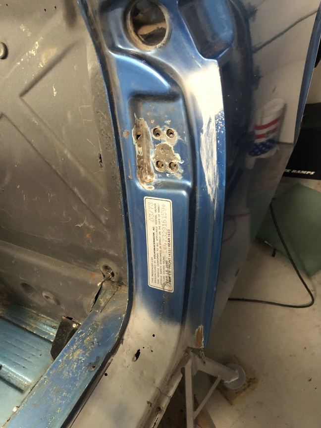
This side doesn't look much worse than the passenger side. However, I'm going to have to replace the jackpoint tube, since I poked through the metal at the bottom when cleaning out rust.
Also, when I unscrewed the latch post, the screw plate underneath wouldn't move. Turns out, that area was packed full of this god-awful light-brown sand. The only heavily-rusted places I've found on this car are places where the sand was packed in -- both jackpoints, the lower driver's latch panel where the vent tubes run and (of course) the pocket for the latch post screw plate. Some DAPO must have driven this car on the beach multiple times (or just one time very enthusiastically).
With some poking and prodding, I finally freed up the screw plate. I also knocked a surprising amount of sand on the floor -- could the inside of that pocket be like a tardis (bigger on the inside)? Unfortunately, it turned out that the backside of the pocket is rusted out, so I'll need to purchase or make a replacement.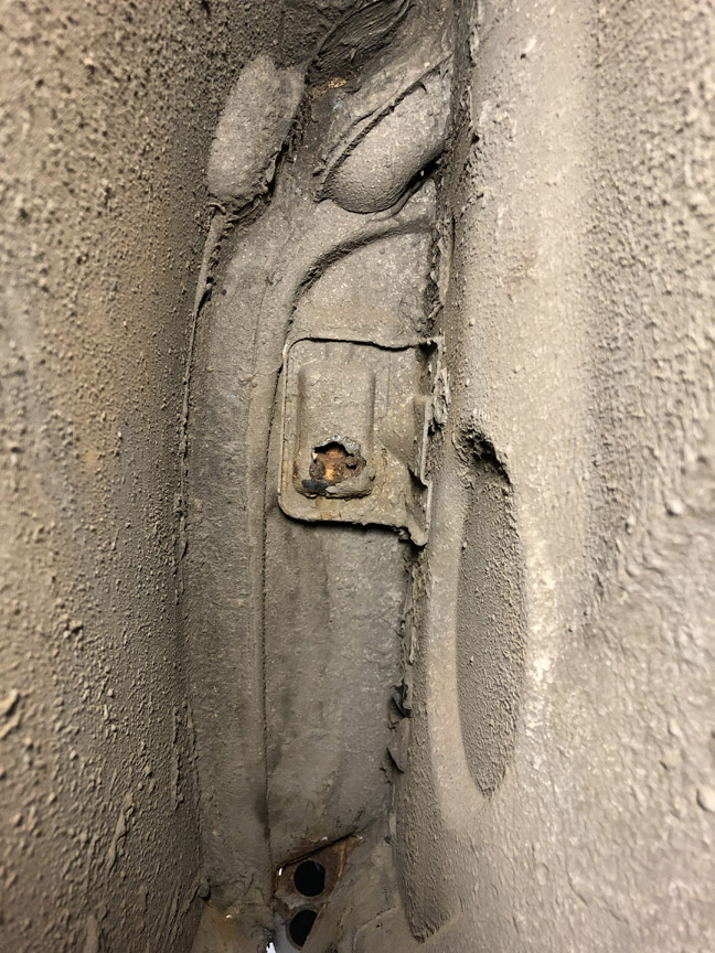
I already have a replacement latch panel, latch reinforcement and screw plate, but can't find a replacement pocket cap (or whatever it would be called).
I'll make one if I have to, but would like to see if a new one is commercially available.
Does anyone know if a replacement for that pocket/cap is available? I've already checked Restoration Design and AutoAtlanta, but can't find the part on either site.
Any leads are appreciated -- looking for the sheet metal piece circled in red.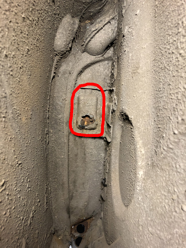
Posted by: BillC Jan 18 2021, 07:27 PM
I was able to spend more time today on the car, stripping off rusty metal. I got the jackpoint pyramid and tube off. And cut out most of the rust at the bottom of the latch panel; not sure how much more I'll be taking off, but at least a little more.
I also cut out the section where the door latch mounts. I was really hoping to leave that section of the latch panel intact and just fill the little rust holes. Unfortunately, I couldn't get the support piece behind it out without better access; so, out it all came....
Here's what it looks like now: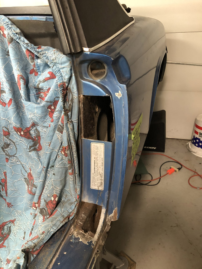
Also, here's what the recessed pyramid area inside the jackpoint looks like: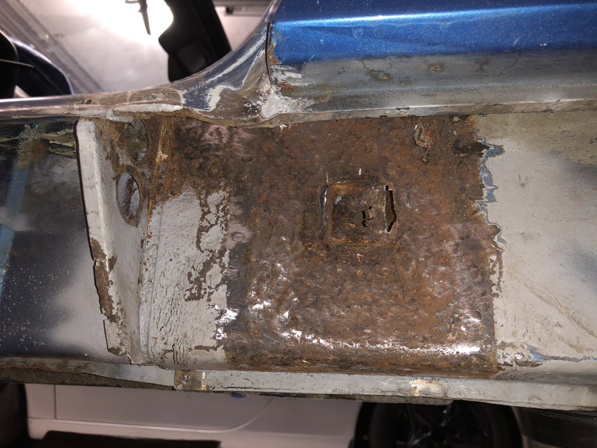
This side is definitely worse than the other side. So, I'm going to make a replacement piece out of some 16ga galvaneal I already have and weld it in. I've left the part in place for now, so I can make a pattern off of it (more masking tape...). It's fairly complex, with four triangular panels and a recessed pocket at the bottom for the jack tube, so it'll end up being two pieces welded together.
Posted by: jaredmcginness Jan 19 2021, 05:38 AM
Nice work! I used 16g for that section on my car and it came out rather nicely. Really sturdy. Should last another 40 years.
Keep it up!
Posted by: BillC Jan 30 2021, 05:10 PM
So I finally managed to get back to the car today, for a few hours. I cut and tacked-in a patch for the hole in the latch area.
Here's the hole where I cut out the rusty latch area, after it had been soaked with Ospho: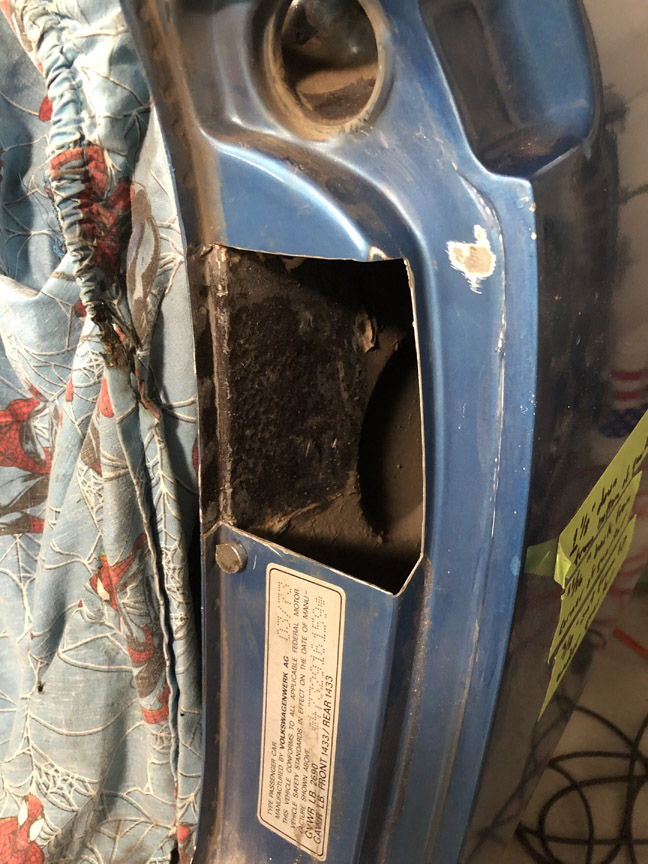
Not shown: once the Ospho was dry, I sprayed the area inside the quarter with high-zinc paint.
Here's the patch fitted, and then tacked in place with the tackwelds ground down.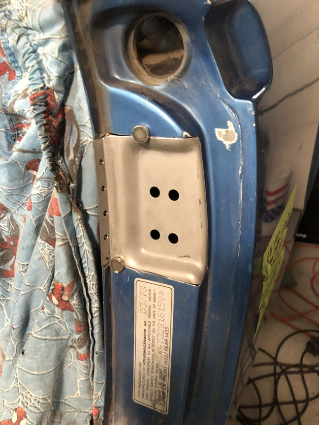
The plan for tomorrow, assuming the weather cooperates, is to finish welding in the patch and then get started on the reinforcement behind the latch.
Posted by: Montreal914 Jan 30 2021, 09:09 PM
Time to take on the last rusty area I've found -- the driver's side latch post and jack point.
Here's what it looks like to start:
This side doesn't look much worse than the passenger side. However, I'm going to have to replace the jackpoint tube, since I poked through the metal at the bottom when cleaning out rust.
Also, when I unscrewed the latch post, the screw plate underneath wouldn't move. Turns out, that area was packed full of this god-awful light-brown sand. The only heavily-rusted places I've found on this car are places where the sand was packed in -- both jackpoints, the lower driver's latch panel where the vent tubes run and (of course) the pocket for the latch post screw plate. Some DAPO must have driven this car on the beach multiple times (or just one time very enthusiastically).
With some poking and prodding, I finally freed up the screw plate. I also knocked a surprising amount of sand on the floor -- could the inside of that pocket be like a tardis (bigger on the inside)? Unfortunately, it turned out that the backside of the pocket is rusted out, so I'll need to purchase or make a replacement.
I already have a replacement latch panel, latch reinforcement and screw plate, but can't find a replacement pocket cap (or whatever it would be called).
I'll make one if I have to, but would like to see if a new one is commercially available.
Does anyone know if a replacement for that pocket/cap is available? I've already checked Restoration Design and AutoAtlanta, but can't find the part on either site.
Any leads are appreciated -- looking for the sheet metal piece circled in red.
I did my own...

Here: http://www.914world.com/bbs2/index.php?s=&showtopic=349463&view=findpost&p=2887081
On your post #96, how did you remove the torsion bars of the engine lid? Was that scary like the ones for the rear trunk?
Posted by: BillC Jan 31 2021, 08:42 AM
I did my own...
Here: http://www.914world.com/bbs2/index.php?s=&showtopic=349463&view=findpost&p=2887081
On your post #96, how did you remove the torsion bars of the engine lid? Was that scary like the ones for the rear trunk?
@http://www.914world.com/bbs2/index.php?showuser=12023
Thanks for the link! That's how I was thinking of making mine. Only difference is that I'll be able weld it to the reinforcement bracket before I weld the bracket in place.
The engine lid torsion bars were very easy to remove. Much less energy involved than the trunk lid springs. First step is to unbolt the deck lid from the car. Then, lay the deck lid upside down on some towels. Then, you'll be able to push down on the torsion bar at the hinge end to slide it out of the notch in the hinge. Then, just unscrew the block in the middle, and work the torsion bars out of the hole on the other end.
I recommend taking some pictures of everything assembled before you take it apart, especially if it's going to be a while before reassembly. I also used masking tape to label each end of the bars, so I could get them back in the same way.
Posted by: Montreal914 Jan 31 2021, 10:28 AM
I did my own...
Here: http://www.914world.com/bbs2/index.php?s=&showtopic=349463&view=findpost&p=2887081
On your post #96, how did you remove the torsion bars of the engine lid? Was that scary like the ones for the rear trunk?
@http://www.914world.com/bbs2/index.php?showuser=12023
Thanks for the link! That's how I was thinking of making mine. Only difference is that I'll be able weld it to the reinforcement bracket before I weld the bracket in place.
The engine lid torsion bars were very easy to remove. Much less energy involved than the trunk lid springs. First step is to unbolt the deck lid from the car. Then, lay the deck lid upside down on some towels. Then, you'll be able to push down on the torsion bar at the hinge end to slide it out of the notch in the hinge. Then, just unscrew the block in the middle, and work the torsion bars out of the hole on the other end.
I recommend taking some pictures of everything assembled before you take it apart, especially if it's going to be a while before reassembly. I also used masking tape to label each end of the bars, so I could get them back in the same way.
Great! Thank you for the procedure, and yes, there could definitely be time between the disassembly and re-assembly. I need to replace one of the mounts on the firewall and I think it will be easier to set the location if I can freely open and close the lid without fighting the torsion bars. The other mount was repaired in the past and the whole lid may not be properly lining up, so that might end up being a complete alignment job.
Good luck with your project, looks like you are making great progress.
Posted by: TX914 Jan 31 2021, 10:32 AM
Very nice work.
Regarding the torsion bars - If there is any sag in the engine lid when open, you can swap the torsion bars (so that they bend in the opposite direction) and it'll be like new.
Posted by: BillC Jan 31 2021, 11:49 AM
I finished welding in the patch and grinding it down this morning. Here's what it looks like: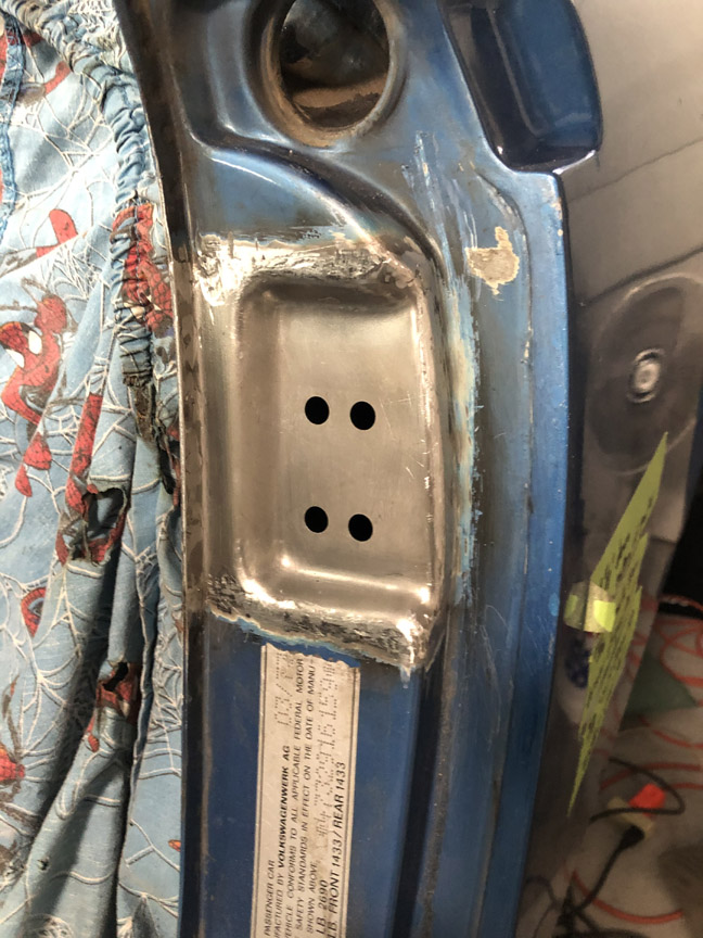
After I finished welding and grinding, I tried fitting the reinforcement panel behind the new panel. Unfortunately, the holes don't quite line up, they're about 1/8" off each other. So, after lunch, I'll first measure the locations for the screw holes in that panel, using the other side as a guide, and adjust whichever set of holes needs adjusting to match. Then, I'll start on the adding the nut plate and cover to the reinforcement that goes behind the panel and weld that in too.
Posted by: BillC Feb 1 2021, 06:20 PM
I measured the holes in the driver's side panel against the passenger side. The height of the holes is the same (yay!), but the driver's side holes are 1/8" further inward than the passenger side (boo!). But, since the cars were hand-assembled, I wasn't completely willing to trust the measurements. So, I remounted the door and checked the latch plate fitment, because now is the time to fix any fitment issues rather then after everything is assembled and painted.
Turns out the measurements were right, and the holes needed to be moved/slotted so the latch plate would end up in the right spot. Only took a few minutes with a rat-tail file, but now I have slots where there should be just holes.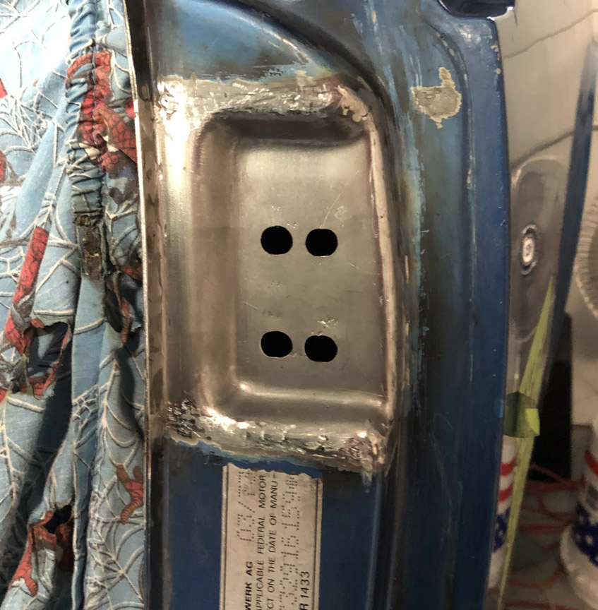
I'm not completely sure if I should leave the slotted holes like they are or if I should weld up the incorrect areas. The perfectionist in me is screaming "weld 'em up!", but my pragmatist side is saying that no one will see the holes once the car is reassembled and to just leave them alone. What do y'all think?
So, with the door post more-or-less fettled, time to look at the parts that go behind the door post. Here are the parts I removed and the new parts from Restoration Design: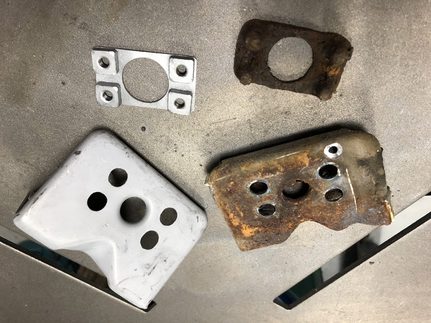
Working from the inside out means starting with the nut plate. The old plate is just too rusty to use, but the new plate doesn't have the deep holes of the old one.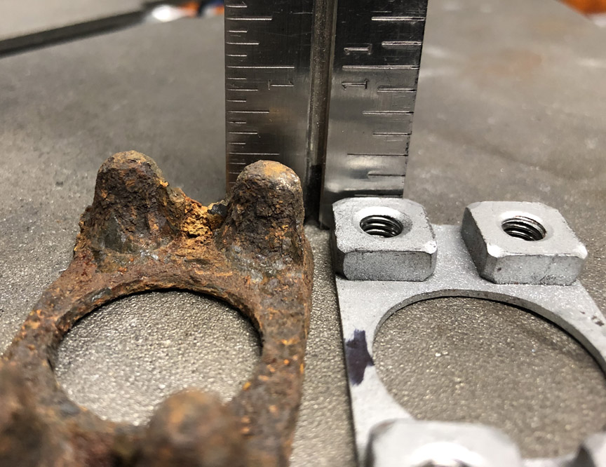
So I decided to add deep holes to the new plate. First step was to weld on some 8mm tubes to give depth (thanks for the tubes, @http://www.914world.com/bbs2/index.php?showuser=22428 ). To make the tubes align, I first screwed a long bolt into a hole and then slid the tube over.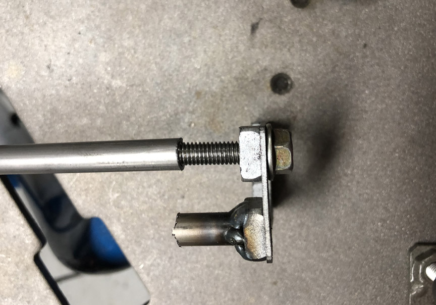
Once welded, the bolt is removed and the tube is cut a little long.
After all four tubes were added, I ground them to length.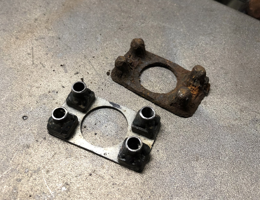
Finally, I capped the tubes with a bit of weld.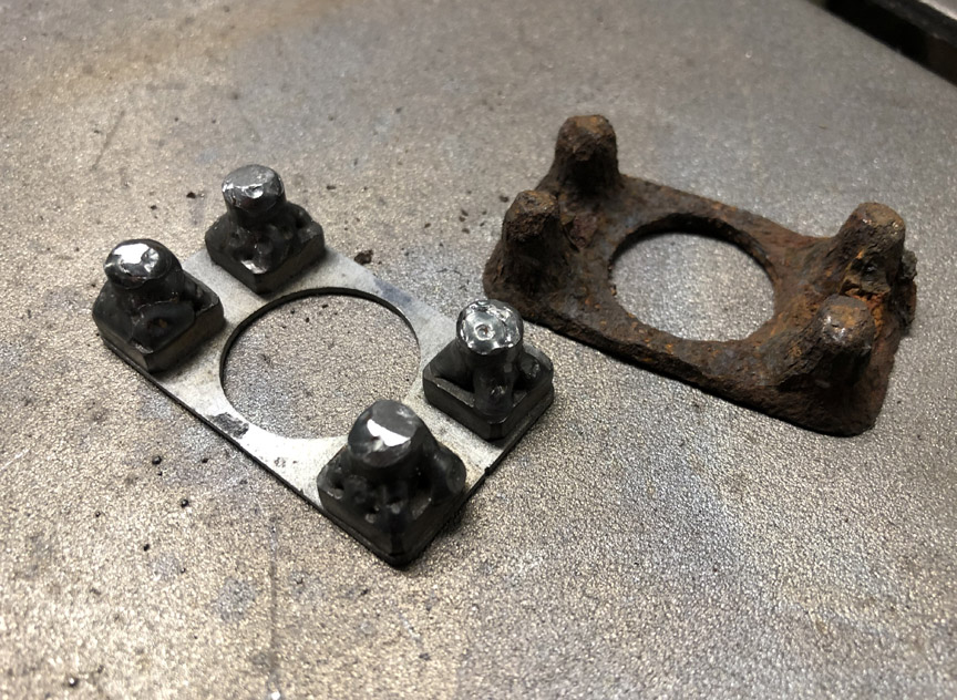
The part was then wire-brushed, had a tap run through each hole and finally painted in high-zinc paint. Once the paint is dry, it'll be ready to install under the cap I still need to make.
Posted by: Superhawk996 Feb 2 2021, 06:41 AM
Nice work. Very creative use of the tube. I love it. Glad to see it going to good use. Otherwise, it would just be sitting in my scrap metal bin, waiting for some unforseen need that may never happen.
Posted by: BillC Feb 6 2021, 05:20 PM
Time to work on the latch plate support bracket.
First step was to put some M6 screws in the nut plate and mark out the travel limits of the plate on the bracket (slide the plate in each direction and then mark with a sharpie):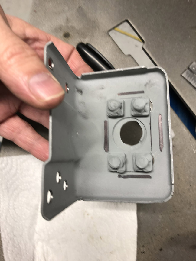
Then, I CAD'ed up a box to fit over the nut plate. In case you didn't know, this is Cardboard Aided Design -- modern ancient technology at it's finest! 
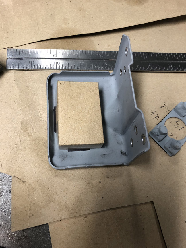
Then, I transferred the design to some sheet metal, cut it out and welded up the corners: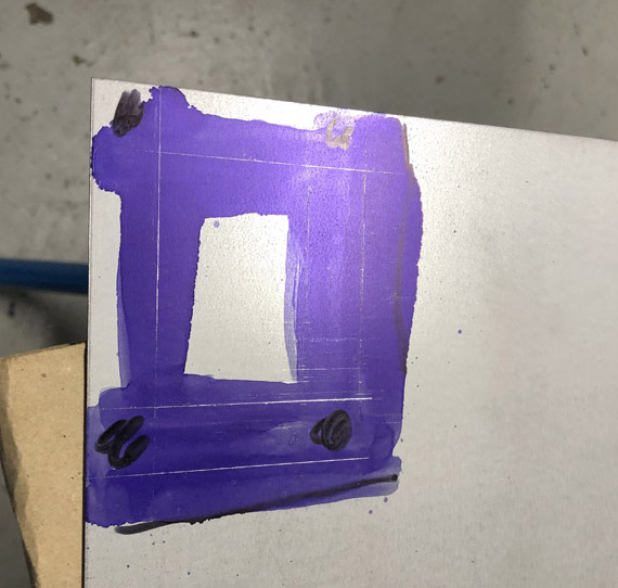
Then, I tacked the box in place on the bracket, making sure the nut plate is both inside the box and could still move around: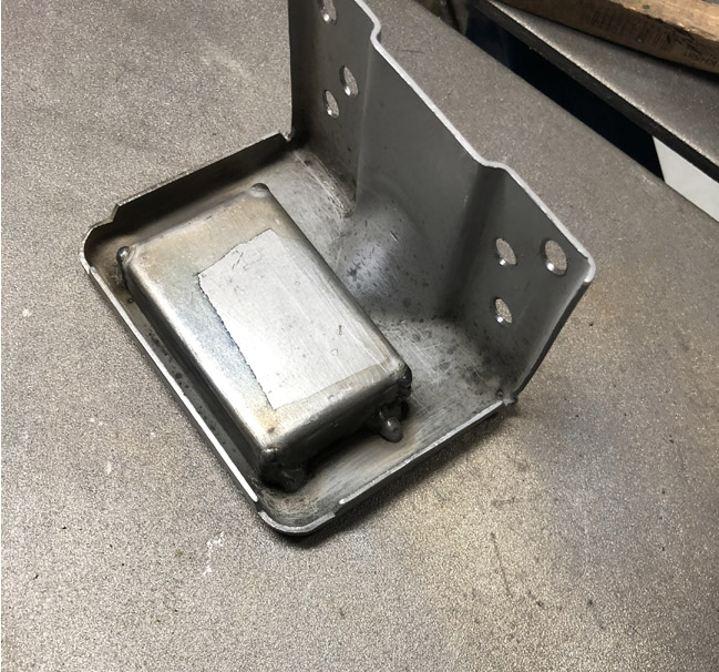
I only tacked it because the box has no structural purpose, and I sealed around it with seam sealer.
Then, I fitted the bracket in place, using long screws with extra nuts to hold the bracket in place for welding: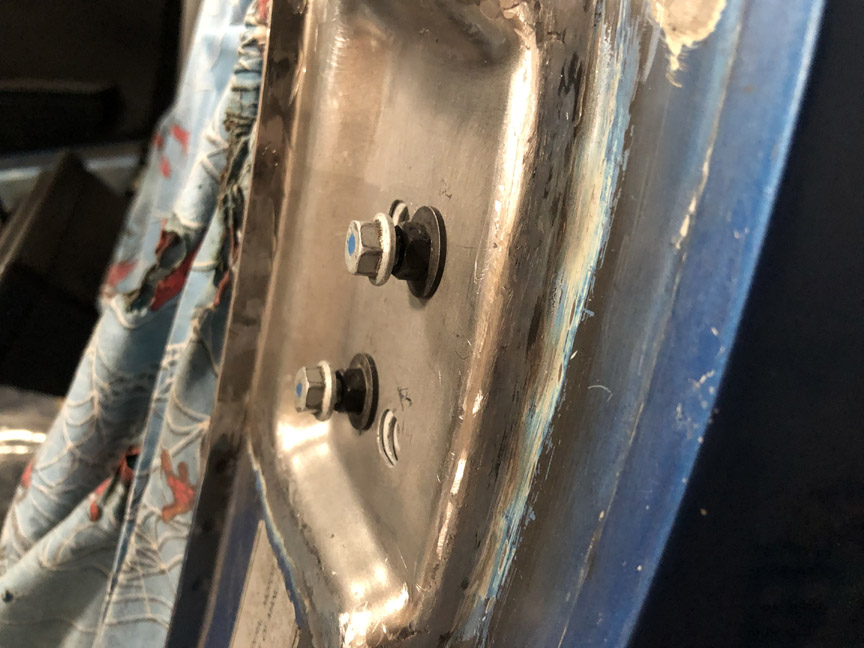
Here's what it looks like all done: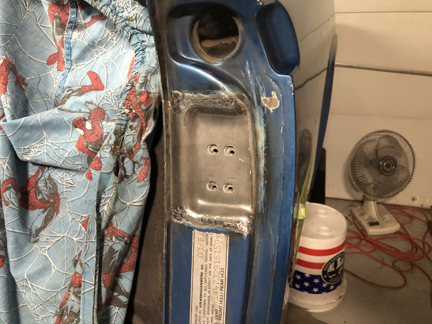
Posted by: BillC Feb 9 2021, 04:50 PM
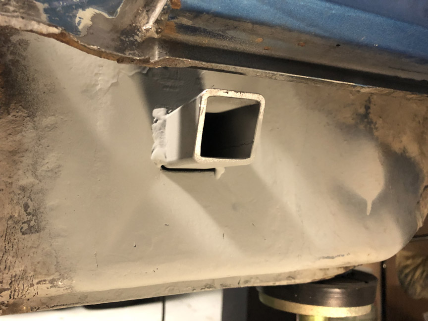
Next step is to replace the rot under the jack point, which looks like this: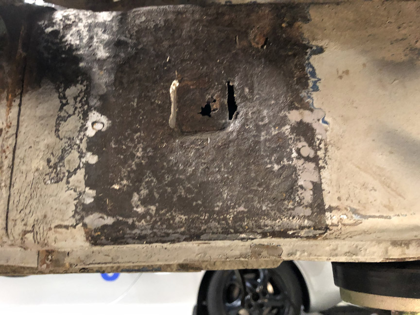
Unfortunately, from this angle it's hard to see the shallow pyramid shape formed into the factory metal, but it's there. That shape is why I'm making a pattern before cutting metal
First step is to make a pattern, using masking tape: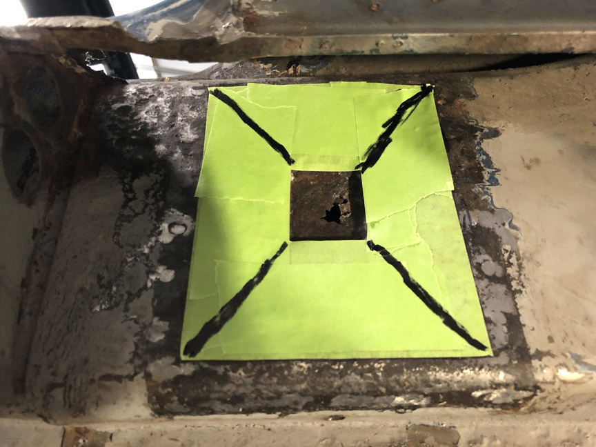
The tape conforms to the pyramid-like shape of the original metal, so I can transfer the pattern to new, flat metal (after cutting the pattern open).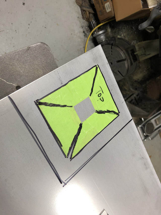
After cutting out the piece of sheet metal (.071" galvaneal from McMaster-Carr), I set up a set of clamps on the mill as a mini pan brake: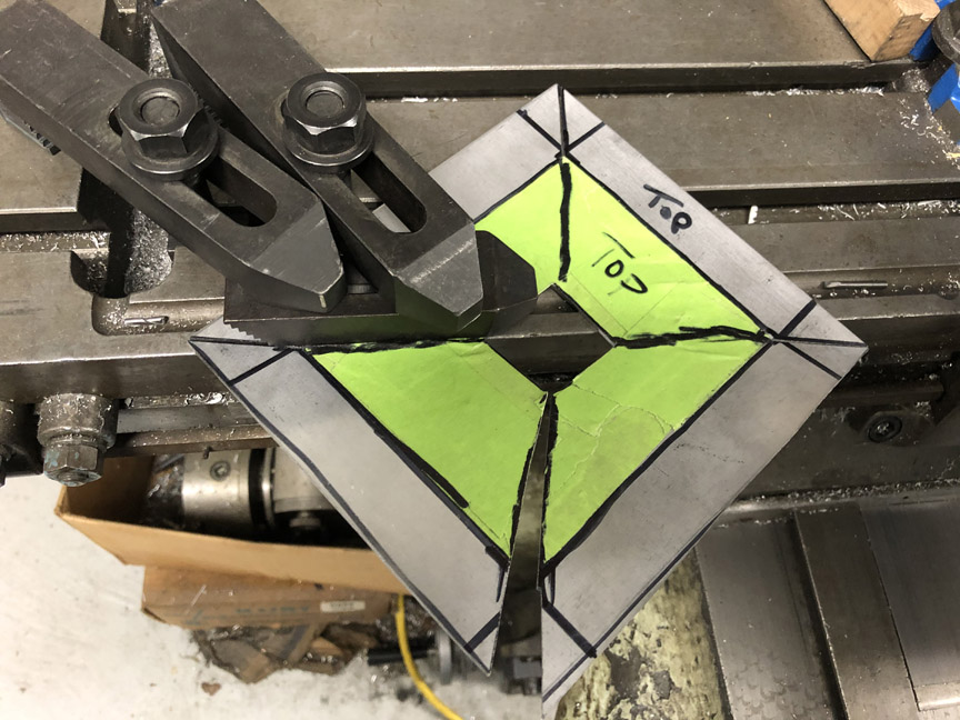
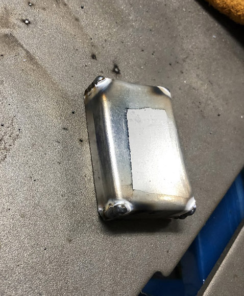
Here's what the metal looks like bent to shape, and then welded: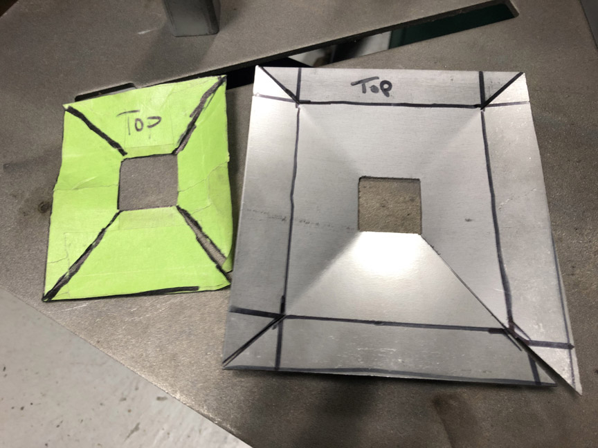
As you may have noticed, I made the part oversize, because I haven't cut out the original metal yet and don't know what I'll find underneath -- at this stage, it's easier to remove extra metal once I know the hole size than to have to add it later. Also, the center "socket" will be another piece formed to match the replacement jack tube and then welded to the backside of this piece.
Posted by: Front yard mechanic Feb 9 2021, 08:41 PM
I think I know what you will find
Posted by: BillC Feb 13 2021, 02:03 PM
I think I know what you will find
Yeah, I suppose you just might at that.
------------------------------------------------------------
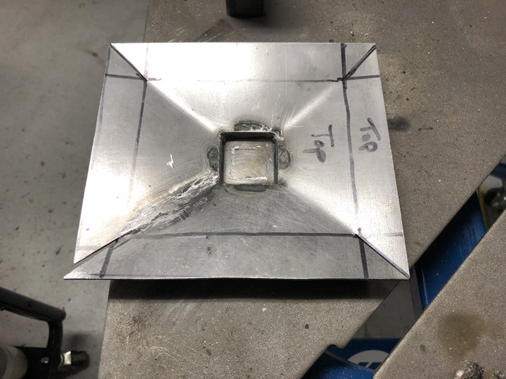
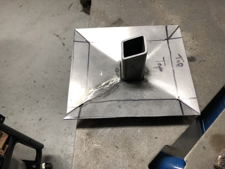
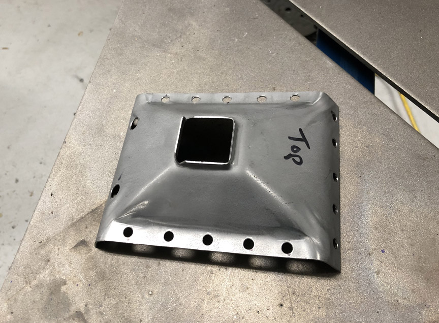
Now it's time to make the recessed center pocket for the jack post.
First steps were to cut out a blank from the same sheet metal and then bend it to shape:
Then, the pocket is held in place with magnets and welded:
Then, the pocked is cleaned up on the face, and the post is put in place. The post is just dropped in for now, to make sure it will fit later for final fitting and welding.
Posted by: Eric_Shea Feb 13 2021, 02:05 PM
RD needs to make that latch box. Not fun. Good work
Posted by: BillC Feb 13 2021, 05:50 PM
Every so often, this car gives me a pleasant surprise. I cut out the jackpoint "pyramid", and this is what it looks like underneath: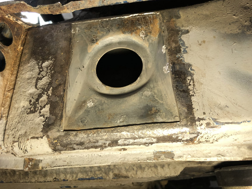
Posted by: Front yard mechanic Feb 13 2021, 08:57 PM
Sweet 
Posted by: Montreal914 Feb 13 2021, 11:46 PM
Very nice find in the long.
Looks like your pyramid will fit perfectly! With such precise CAD work, not surprising 
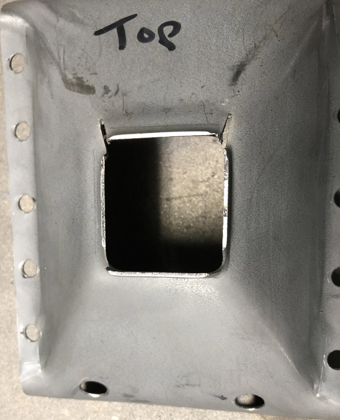
Posted by: BillC Feb 17 2021, 07:57 PM
Had some free time this afternoon to finish welding and grinding the inner pyramid replacement. Doesn't look too horrible: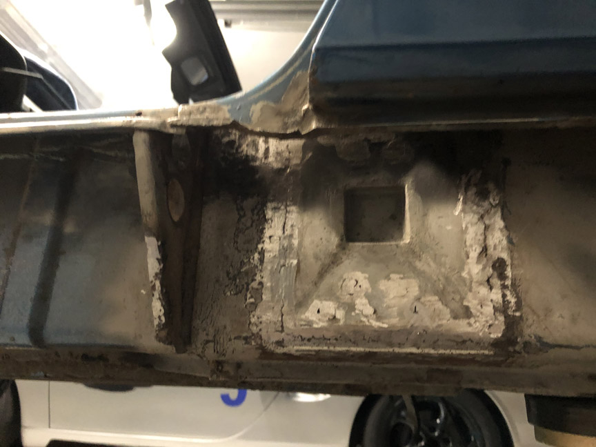
Next steps will be to fit the jackpoint tube and the outer pyramid. Both of these are replacements from RD, so that should go faster.
Posted by: seanpaulmc Feb 18 2021, 08:01 PM
Had some free time this afternoon to finish welding and grinding the inner pyramid replacement. Doesn't look too horrible:
Next steps will be to fit the jackpoint tube and the outer pyramid. Both of these are replacements from RD, so that should go faster.
Very nice work! Please keep it going.
I need this play by play for referencing. The fender does not look to be cut. When putting the jack receiver and plate back in how will you weld in the top portion?
Thanks,
Sean
Posted by: BillC Feb 20 2021, 05:58 PM
The fender does not look to be cut. When putting the jack receiver and plate back in how will you weld in the top portion?
The rear quarter isn't cut. I'm trying to minimize the amount of sheet metal I have to cut to get to the sheet metal that needs to be fixed. Just like the passenger side (see page 5), I did the top welds through the rear wheel opening inside the rear quarter -- I added a pic of this at the bottom of this update.
----------------------------------------------------------------------------------------------
And on to the next steps:
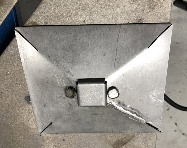
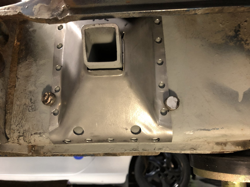
First step was to install the jackpoint tube. Before I cut out the old tube, I took careful measurements to make sure the new tube ended up in the same position. So, once the new inner pyramid was in, I started fitting the new tube. I held it in place and put a single tack weld. Then, I moved the tube to position and added two more tacks. Unfortunately for me, the tube moved a little while tacking and I had to cut the tacks, reposition the tube and re-tack it. Second time got it right, so I welded it all up. Then I painted the entire area under the outer pyramid with high-zinc paint. Here's how that came out:
While I was waiting for the paint to dry, I prepared the outer pyramid part. This consisted of punching out twenty 1/4" holes along the perimeter and then drilling two 3/8" drain/vent holes near the bottom. Here's how that looked:
Once the paint dried, I tried fitting the new outer pyramid. But, unlike the passenger side, this side wouldn't quite fit without modification. I used the dremel tool to cut two little slices, to tweak the upper lip out enough to clear the post:
Here's what the pyramid looked like when fitted into place, with "fuzzy" magnets holding it in place:
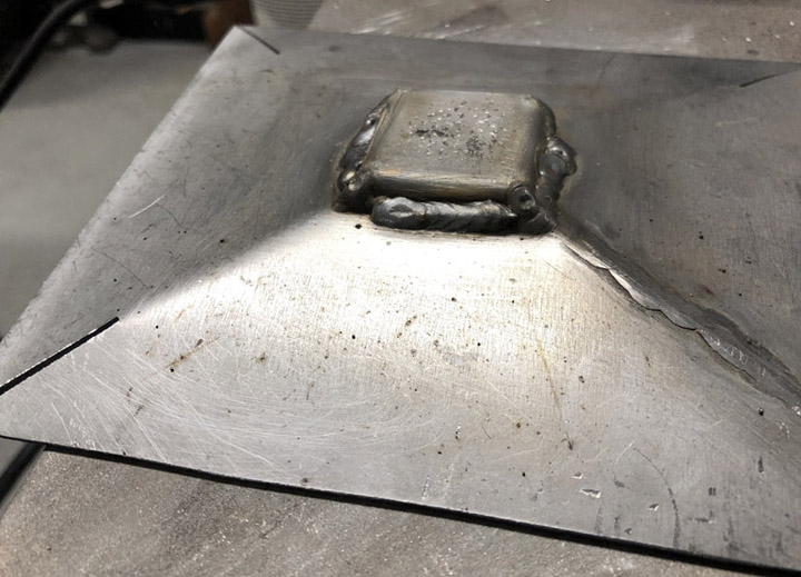
I then plug-welded the mounting holes. Then, I used an old cold chisel and a hammer to close the opening around the jackpoint tube, and then welded that up too. Finally, I ground down the plug welds with the little belt sander.
And, since someone asked, I welded up the three rear top plug welds inside the rear quarter, through the rear wheel opening. It's very tight in there, and it was a real PITA, but it's better then cutting the quarter open.
I got the front two plug welds through the hole cut in the door sill. That hole was cut because of the rust holes in the corner. Otherwise, I would have had to do all five holes through the quarter, like the passenger side.
Posted by: BillC Feb 22 2021, 08:17 PM
Managed to sneak in some time on the car last night and tonight.
Time to patch what appears to be the last big hole on the car, at the bottom of the door opening: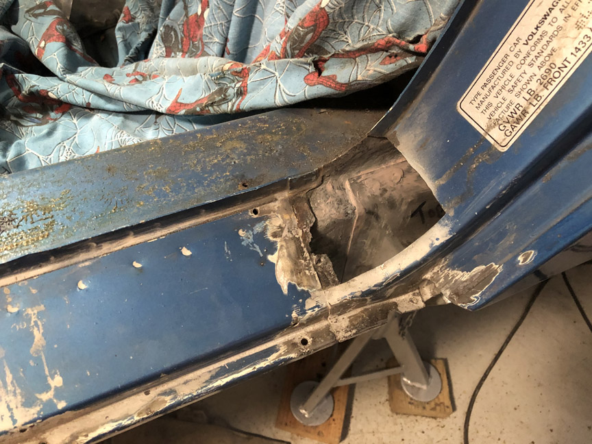
This will get two separate patches, one on the bottom and one for the curve. Here's the bottom patch fitted: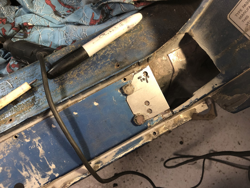
And then welded in and ground down: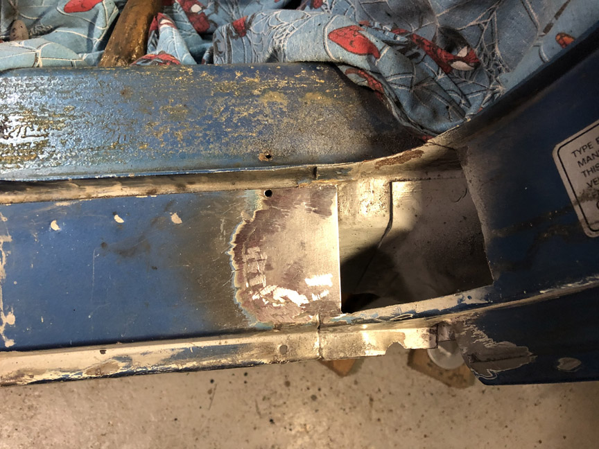
Last thing I was able to do before having to call it a night was to fit the second patch: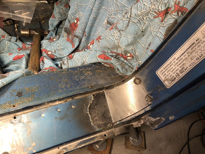
I'm hoping to be able to finish the second patch before the weekend.
Posted by: BillC Feb 27 2021, 11:32 AM
Welded in the patch last night, and ground it down this morning. With any luck, this is the last large patch I'll need to weld into the 914 (at least for a while).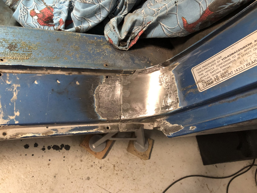
Now I need to prep and paint the door opening. Unfortunately, this is my least favorite part of working on a car. Also one of the slowest parts, since it requires waiting for everything to dry and/or harden -- not good for those of us who are patience-impaired.
Posted by: BillC Mar 12 2021, 06:56 PM
And . . . another milestone achieved -- driver's door is back on!
Since it's just bodywork -- a little filler, a lot of sanding, then primer and paint -- I'm just going to show the final product. Here's what the door opening now looks like: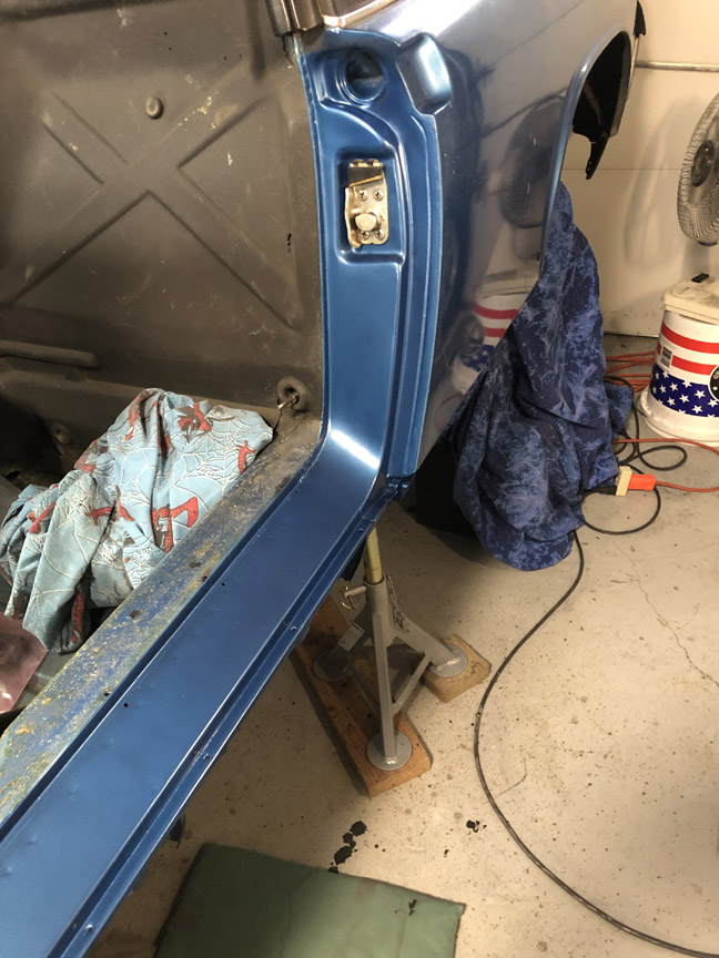
And with the door re-mounted and adjusted: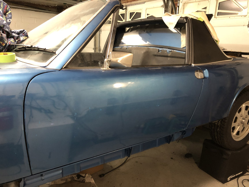
I still need to reinstall the vent lines and the door card, but those shouldn't take too long. There's a little more work in the engine compartment to wrap up, then on to the engine!
Posted by: seanpaulmc Mar 12 2021, 07:00 PM
Your skills are fantastic. Looks great!
What are you using for paint and for spraying?
Thanks,
And . . . another milestone achieved -- driver's door is back on!
Since it's just bodywork -- a little filler, a lot of sanding, then primer and paint -- I'm just going to show the final product. Here's what the door opening now looks like:
And with the door re-mounted and adjusted:
I still need to reinstall the vent lines and the door card, but those shouldn't take too long. There's a little more work in the engine compartment to wrap up, then on to the engine!
Posted by: BillC Mar 12 2021, 07:06 PM
Your skills are fantastic. Looks great!
Thanks!
What are you using for paint and for spraying?
Just rattlecans, paint and primer from paintscratch.com. If/when I ever do a full restoration on the car, I'll either pay someone to paint it properly or at least buy a new spray gun setup.
Posted by: BillC Dec 29 2023, 05:25 PM
Hard to believe it's been almost three years since I've worked on this car. All the usual excuses apply -- life, kids, wife, work, etc. Plus, I built a Spec Boxster and started PCA Club Racing.
Anyway, it's time to get back on the car. I'd really like to get it drivable by summertime (gotta have a goal, even if it's fantasy....).
I decided to re-start with the guide tubes for the heater control cables. Not sure why, but someone went crazy with a cutoff wheel and removed the tubes, leaving short stubs.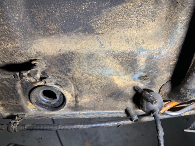
I know the proper, concours-correct fix would be to remove the old guide tubes and braze in new ones. However, the goal is to get the car drivable and enjoyable again, not compete at Pebble Beach, so I'm going to take a simpler approach.
First, I cleaned up the stumps and ground back some of the factory brazing, to expose as must stub as possible. Then, I cut pieces of 3/8" steel brake line and shaped them to fit over the stubs, and then cut pieces of 5/16" steel brake line to replace the missing sections of tube. The brake line is nice because the two sizes are slip fits over each other and the stubs. Plus, I can keep the flared ends of the line to replace the factory flares.
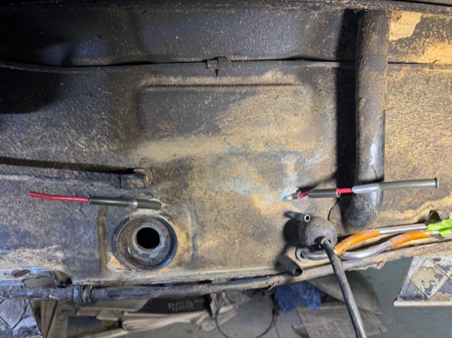
The red things are 10-ga wire. I stripped back about 1/4", flared the copper strands and stuffed them inside the tubes.
Finally, I glued everything in place with JB Weld. After I glued all the pieces, I pulled the wires out, cleaning any extra glue out of the tubes, to make sure the tubes were not blocked by the glue.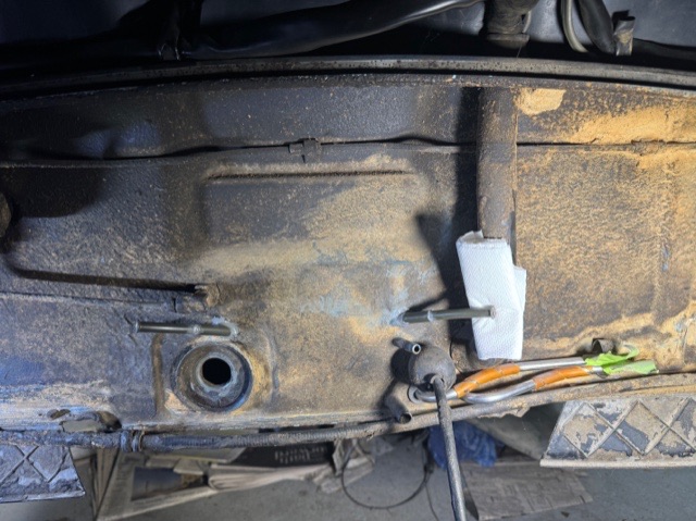
The folded-up paper towel is just to hold the tube in place until the glue dries. Don't worry, it won't stay there.
I thought about welding the lines on, but there's no easy way to get the welding torch around the back sides of the stubs, plus it is very tight in there. I also thought about brazing the pieces in, but with my luck I'd set all the stuff left in there on fire. As things are, I can always remove the pieces later on when it's finally time for the full restoration.
Posted by: Geezer914 Dec 29 2023, 06:06 PM
Nice work and love the color. Suggestion, mount the fuel pump and filter under the steering rack. When you need to change the fuel filter you just have to drop the pan instead of pulling the tank. Also replace the plastic fuel lines with Tangerine Racing stainless fuel lines with the engine and tank out of the car.
Posted by: BillC Dec 29 2023, 06:35 PM
Nice work and love the color.
Thanks!
Suggestion, mount the fuel pump and filter under the steering rack. When you need to change the fuel filter you just have to drop the pan instead of pulling the tank.
I've been thinking about doing just that. We'll see how things are going when it gets closer to actually starting the engine.
Also replace the plastic fuel lines with Tangerine Racing stainless fuel lines with the engine and tank out of the car.
Already done. If you look at the pics, you can see the stainless fuel lines at the bottom of the firewall. The orange "wrap" on the stainless lines is actually the original vinyl fuel lines repurposed -- I cut them in a spiral and wrapped them around the stainless lines, they make good "bumpers" to prevent rattles and wear.
Posted by: 930cabman Dec 31 2023, 11:14 AM
Just happened on your thread, great workmanship.
Please keep this going, it will put a smile on your face quickly and keep it there
Posted by: BillC Jan 1 2024, 08:27 PM
Given the history of everything else I've found with the car, I decided to go through the engine before reinstalling it. I got as far as taking the accessories and shrouds off of it, and found plenty of issues.
So, here's what I started with: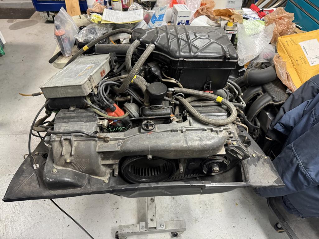
As previously mentioned, someone put a fuel pressure regulator where the decel valve was supposed to go (and also left the small vacuum line open to atmosphere).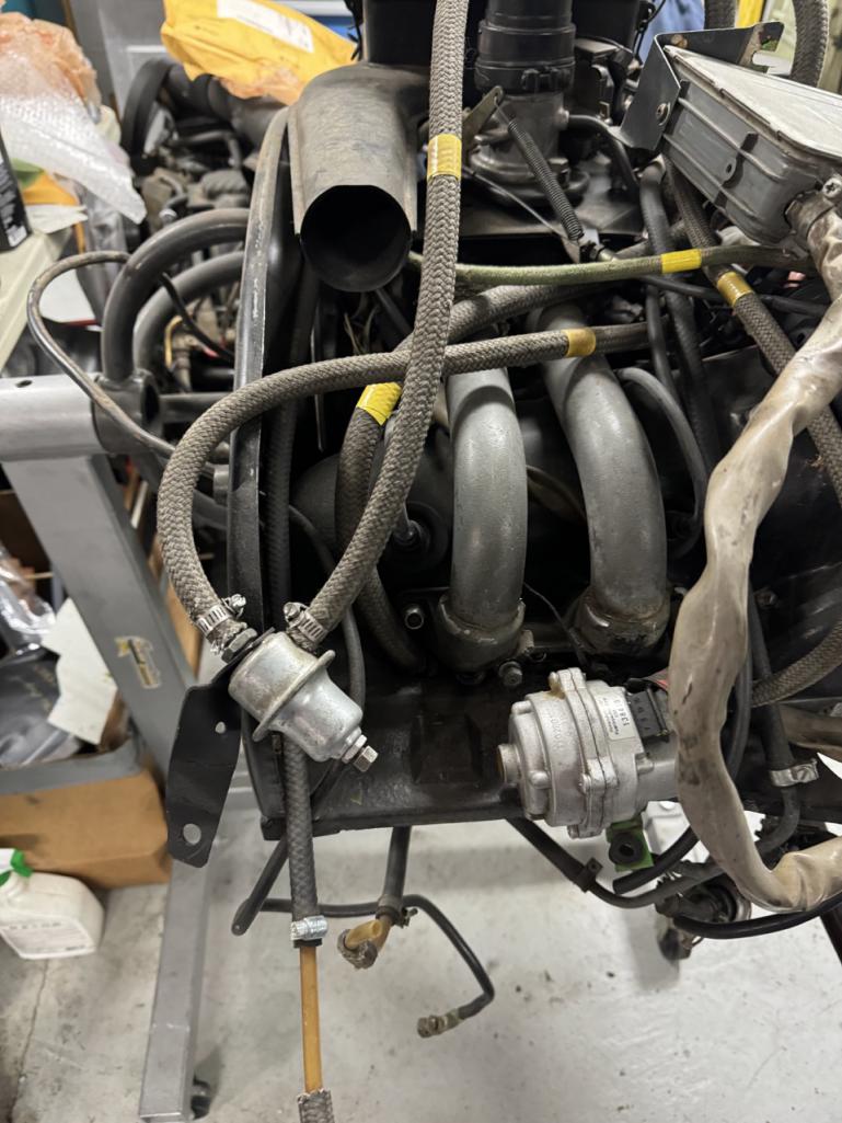
I found more kinked fuel lines: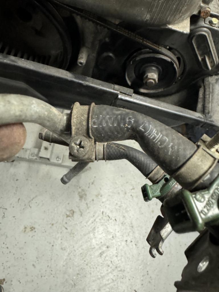
All four of the injector fuel lines were like that.
And, once I got the shrouds off, I found this: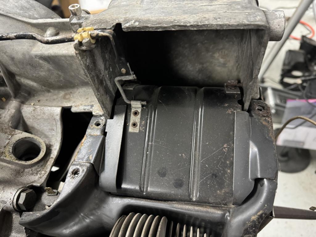
Can anyone tell what's wrong with this pic? I'll give you a hint -- there's no thermostat.
Posted by: ClayPerrine Jan 2 2024, 04:30 PM
Given the history of everything else I've found with the car, I decided to go through the engine before reinstalling it. I got as far as taking the accessories and shrouds off of it, and found plenty of issues.
So, here's what I started with:
As previously mentioned, someone put a fuel pressure regulator where the decel valve was supposed to go (and also left the small vacuum line open to atmosphere).
I found more kinked fuel lines:
All four of the injector fuel lines were like that.
And, once I got the shrouds off, I found this:
Can anyone tell what's wrong with this pic? I'll give you a hint -- there's no thermostat.
That "flap" is on the wrong side of the tabs. The way it is installed, it can never move. Probably done to make sure it didn't move because of the missing thermostat.
Posted by: 930cabman Jan 2 2024, 04:58 PM
Not necessarily a DAPO, unless you know the guy, probably one of the mechanic's who had touched this example.
Great looking work, ETA?
Posted by: BillC Jan 2 2024, 07:09 PM
That "flap" is on the wrong side of the tabs. The way it is installed, it can never move. Probably done to make sure it didn't move because of the missing thermostat.
Exactly. Probably done as you said, but seems to be more of a guess than a plan (see comment below).
Not necessarily a DAPO, unless you know the guy, probably one of the mechanic's who had touched this example.
I don't know. Locking the flaps open makes sense, but the spring on the flap rod also does that. However, they left the threaded hole in the block where the pulley attaches open and unplugged. It seems to me like someone who knew what they were doing would know to plug the hole, since it's open to the inside of the block. At least the open bolt hole explains all the oil under the engine.
ETA?
Not sure, but I'm hoping to have it drivable by summertime.
Posted by: BillC Jan 20 2024, 06:35 PM
We're back from our vacation trip, and time to get back to work on the car.
First, I took a look at the cylinder head temp sensor, to see what was installed. I couldn't see any numbers, so I thought I'd take it out for a closer look. But, it was very loose. Upon removal, I discovered the hole is stripped. <sigh> The DAPO gifts keep on giving....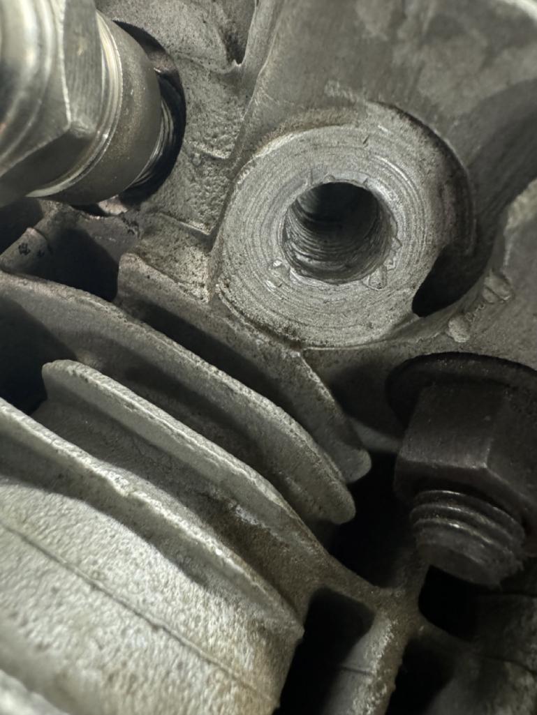
So, I have ordered a helicoil kit (10mmx1.0), which should arrive Monday.
But, it turns out the CHT has no numbers on it at all, so I have no idea what it is supposed to be. Does anyone have a good 017 CHT available? (I already have a wanted ad posted in the classifieds forum)
Then, I decided to move on and adjust the valves. They were all on the snug side, so I'm guessing the previous owner never adjusted them after the rebuild. They are set properly now.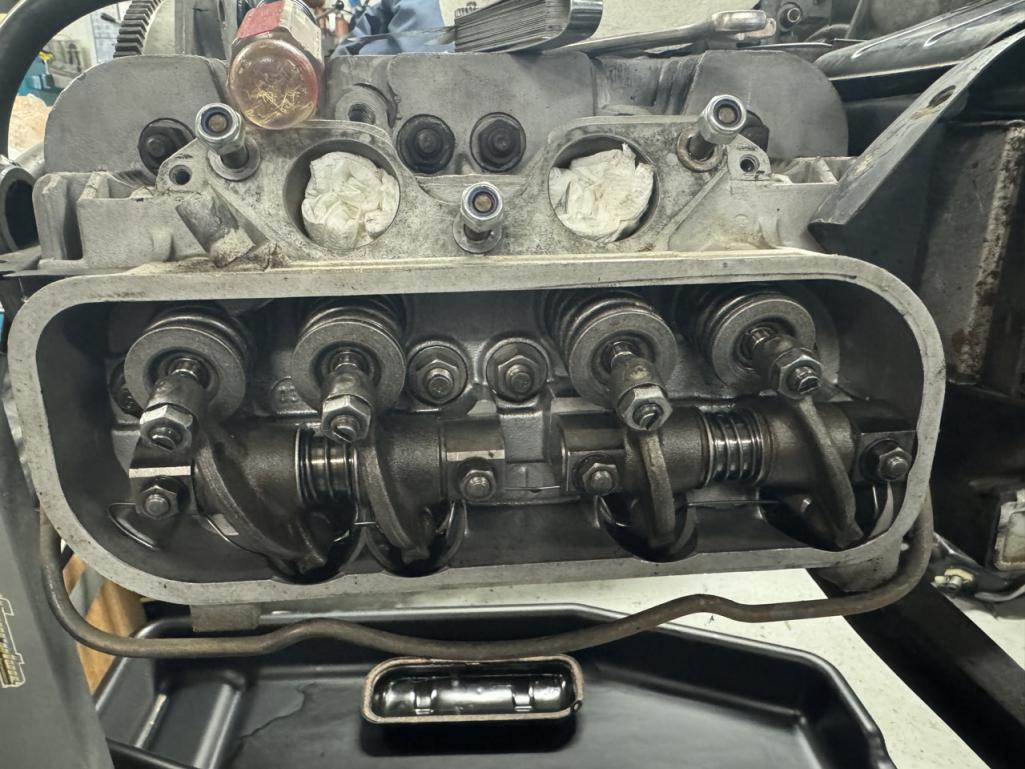
Next step was to add in some wiry goodness thanks to @http://www.914world.com/bbs2/index.php?showuser=104 -- new harnesses for the engine.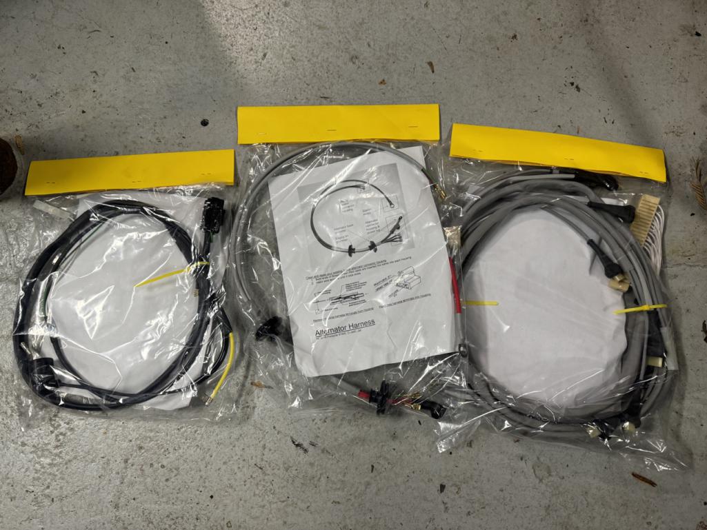
I installed the generator harness, and will put the others on as the engine progresses. Once I get all harnesses installed, I'll (finally) return the old ones for the core refund, if it isn't too late.
I then moved on to installing a new taco plate and deep sump (tuna can) from 914Werke. First step was to get the old ones off: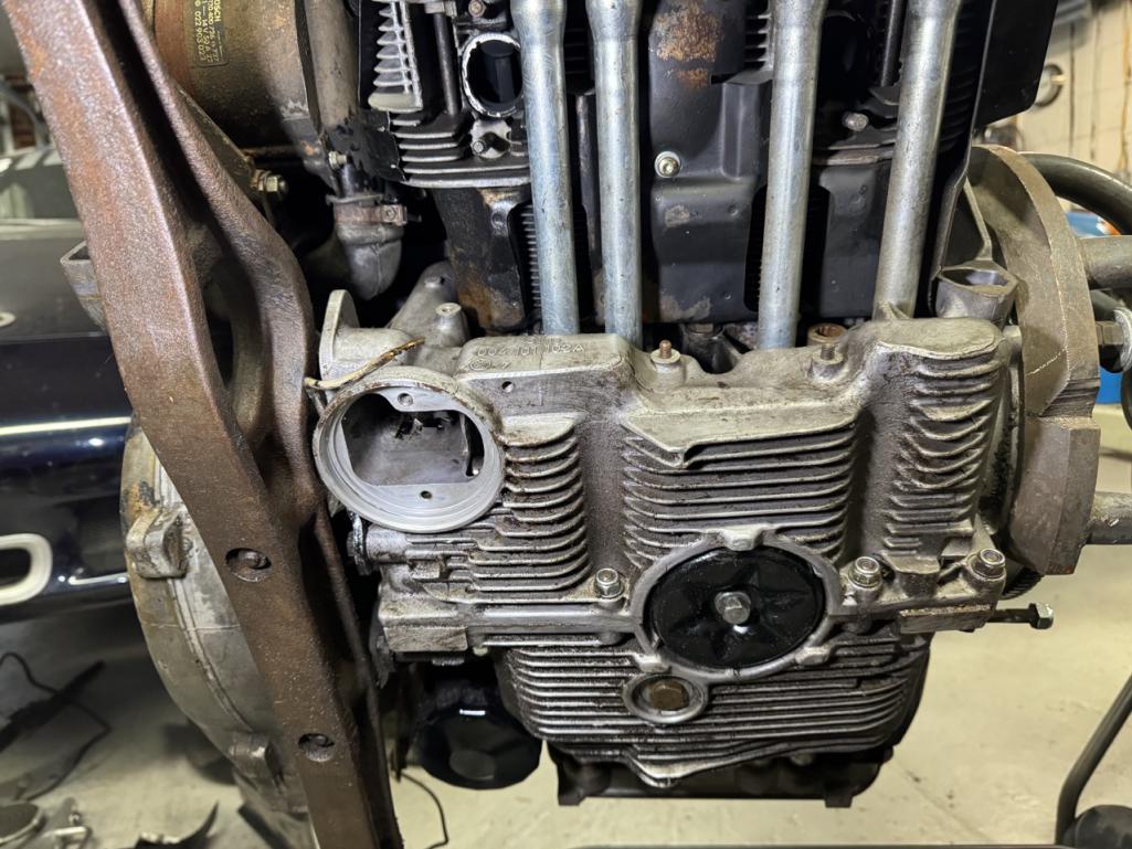
I made one change to the bottom plate for the tuna can. I checked the stock bottom plate, and the bolt flange is actually higher than the mounting rim (when installed). So I decided to take about 1/8" off the aluminum bottom plate, to raise it a little bit.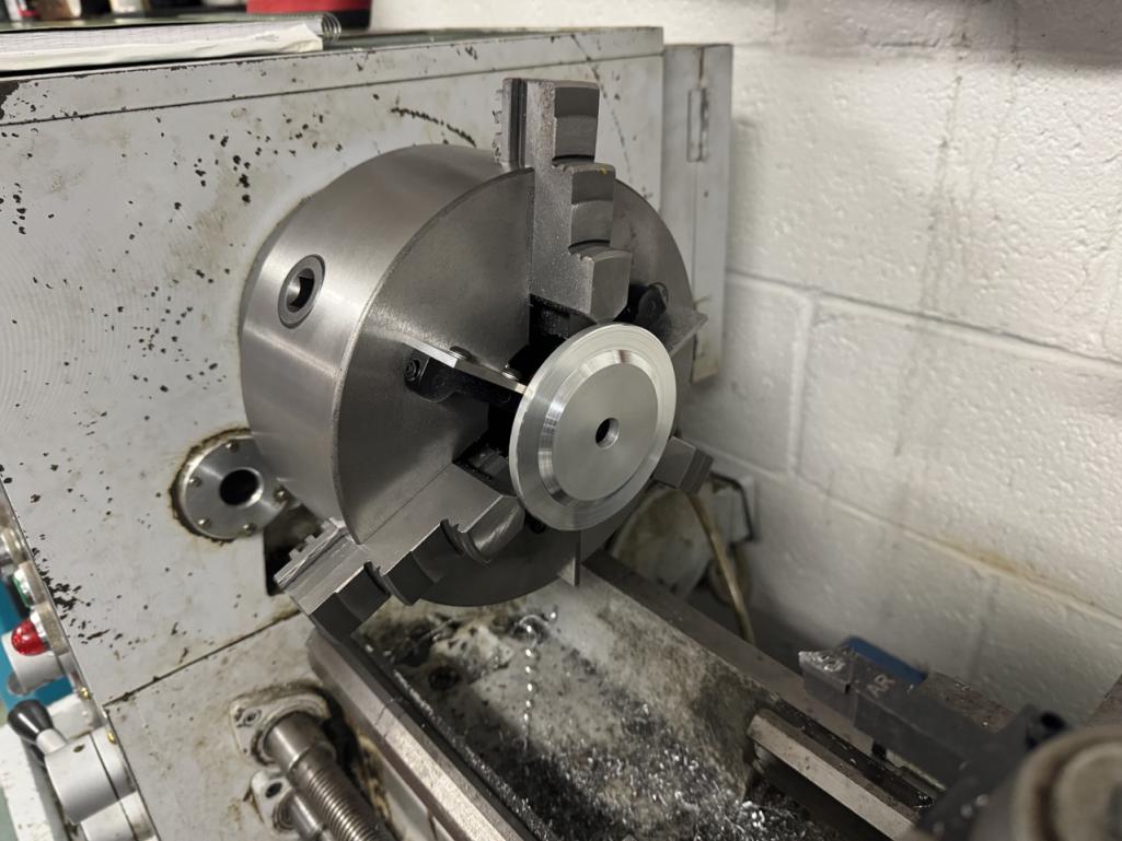
Then, I finished installing everything, including the oil strainer. Because there were now three layers of gaskets, and 9 ft-lb just doesn't seem like much, I used Yamabond on all the gaskets and under the bolt head.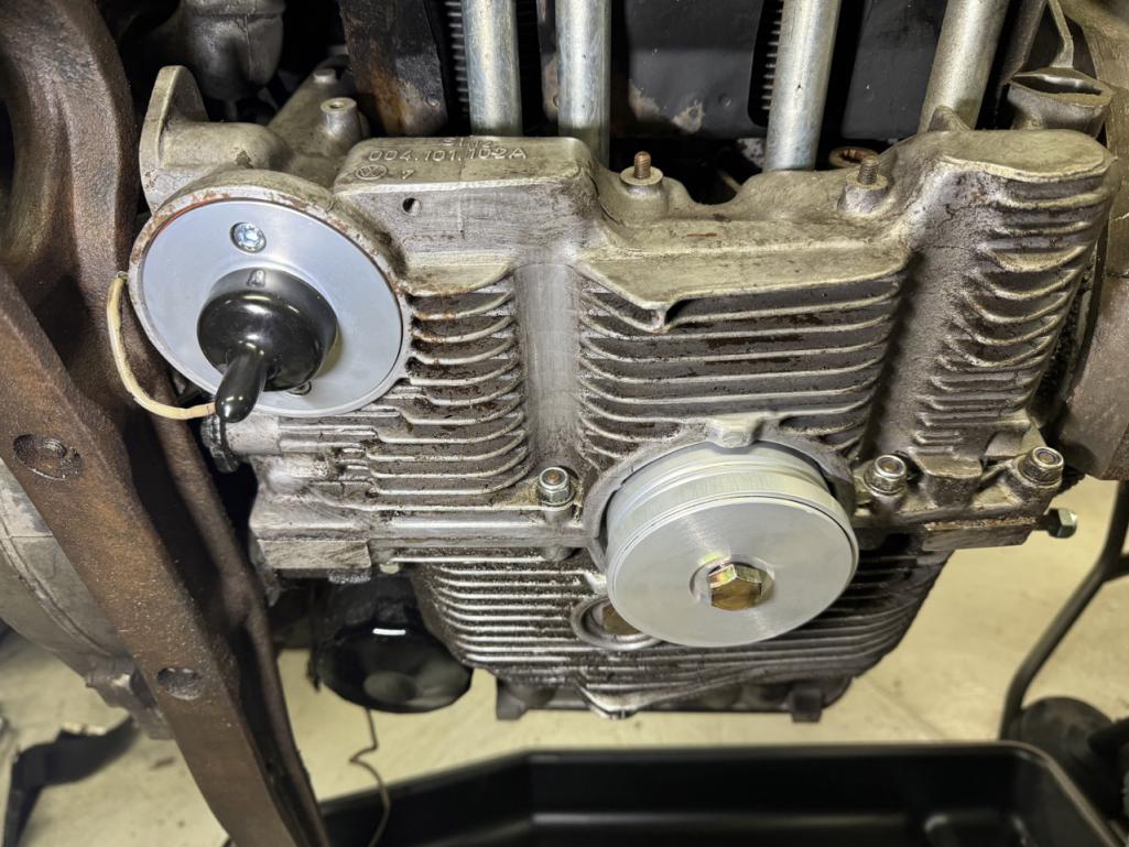
Hopefully no leaks.
Posted by: BillC Jan 25 2024, 05:16 PM
Had sporadic chances to work on the engine over the last few days. In that time, I painted the timing marks on the fan (and the fins near the marks), cleaned & inspected the throttle body & intake manifold, reset the distributor drive to the correct angle (12 degrees), helicoiled the CHT hole and installed the CHT, and reinstalled the cooling shrouds.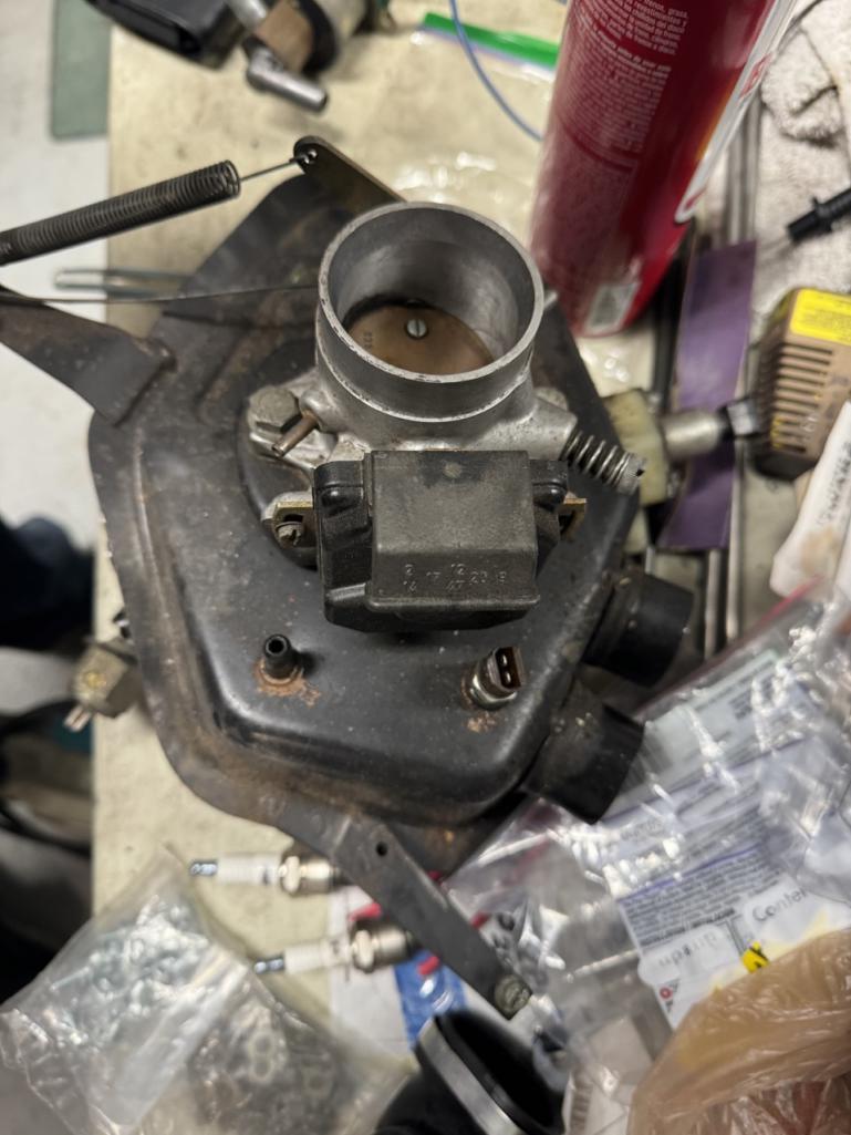
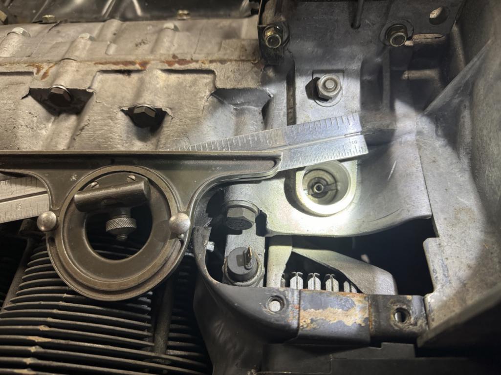
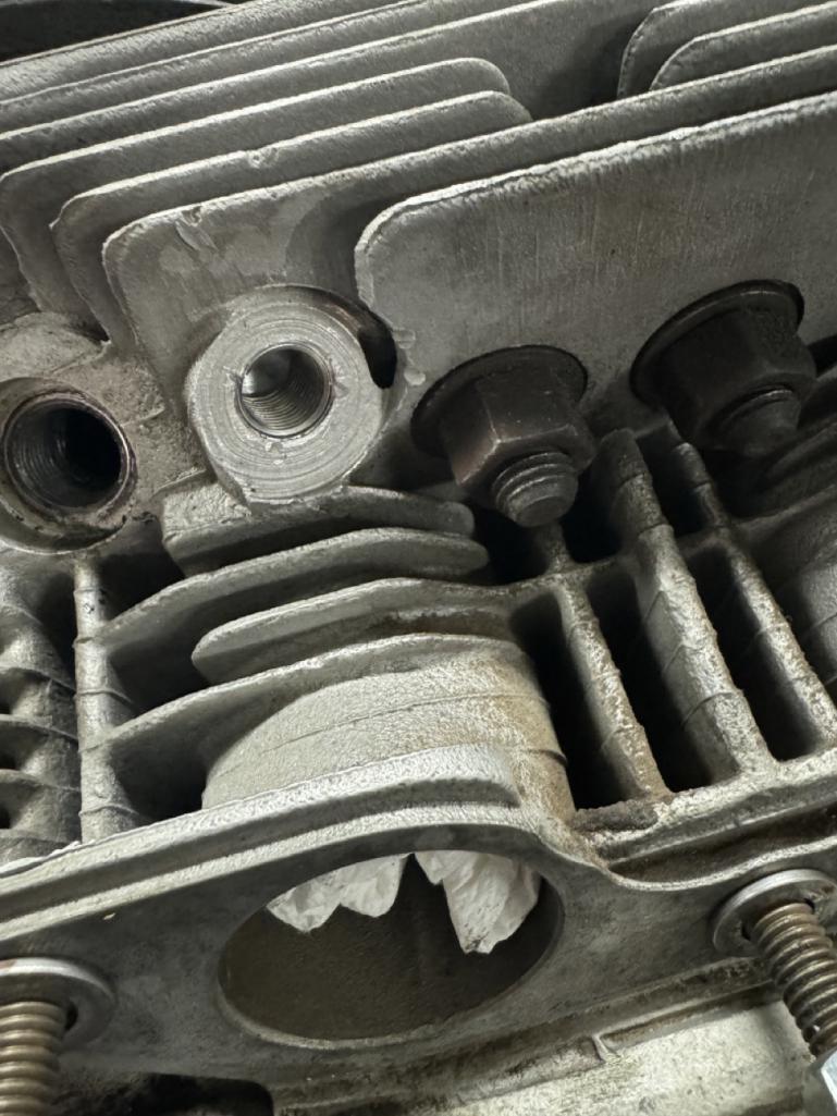
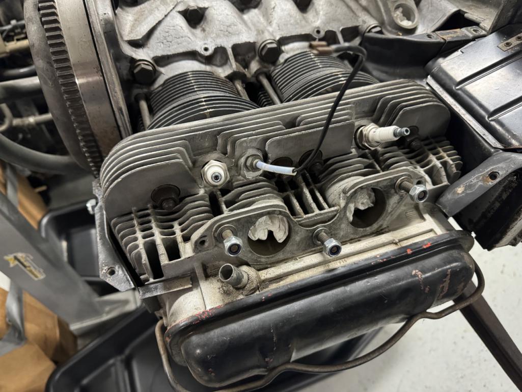
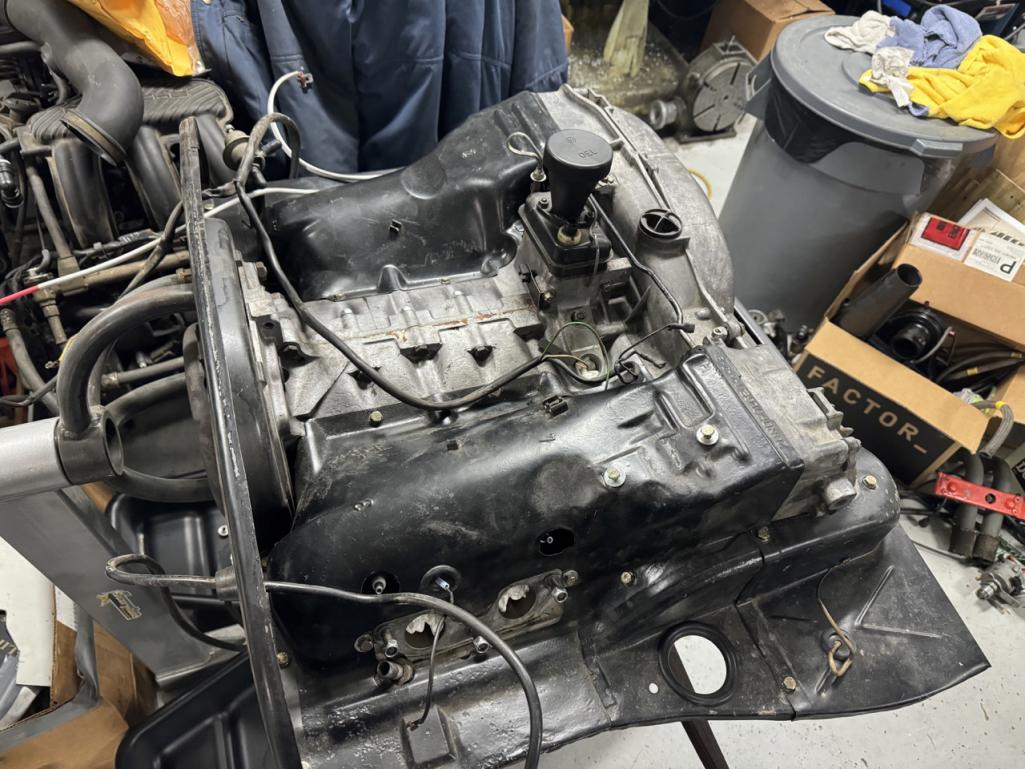
It turns out that a long, slender pair of c-clip pliers work great for pulling the distributor drive. Also, I rotated the engine on the stand so the distributor drive was exactly vertical, so the thrust washer under the drive wouldn't move around and fall into the case.
Also, I just installed an old 012 CHT. I'm still trying to find a good, used 017 CHT at a reasonable price, and the car came with a generic 012, so I'll try this for now.
I also discovered there's an oil leak somewhere on the front of the engine, so I'll be pulling the front shroud pieces back off and probably the engine mount bar too. At this point, it looks like the leak might be from the bolts that hold the mount brackets to the engine case.
Posted by: BillC Jan 30 2024, 08:04 PM
While the engine was just sitting on the stand, waiting for more parts to arrive, it dripped a few drops of oil into the pan underneath. This seemed a bit odd, since I had already drained all the oil out of it. To try to find the source, and make sure it wasn't one of my new additions, I grabbed a pointer and hung it from various points under the engine to track the drip back up to the source. The drip turned out to be coming off the left engine mount bracket, which continued the seeming oddity, since the bracket bolt holes are not through holes.
So, I removed the engine mount brackets and found the source of my leak: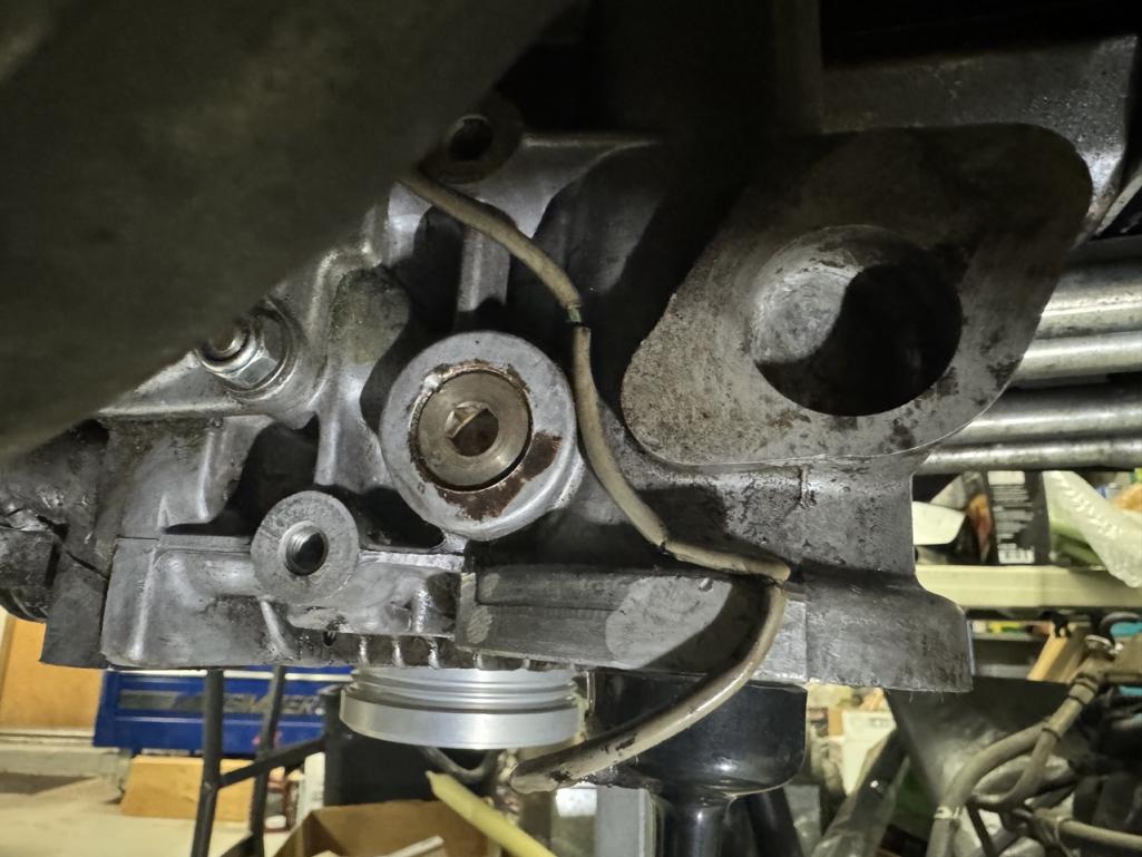
That is a straight-thread steel plug in an aluminum hole. From what I've been told, that's a factory part (smh). Anyway, the plug was a little loose, with only the factory stake holding it in -- it turned right out with almost no effort. FYI, the plug is 22mm with 1.5mm thread, straight thread (no taper), and is about 9mm thick.
I asked for advice on the forum, and the general consensus was that a straight-threaded steel plug was not really the right part for the application. But, no one makes a direct-replacement aluminum plug. The options came down to either a brass plug or make my own.
@http://www.914world.com/bbs2/index.php?showuser=23343 linked to his thread where he faced the same issue. He ended up going with a brass plug, but @http://www.914world.com/bbs2/index.php?showuser=24781 had added a link to a place selling aluminum flange plugs with the right thread. That seemed like a promising path, so I ordered a few (one to use and spares, just in case).
Here's what arrived, next to the original plug: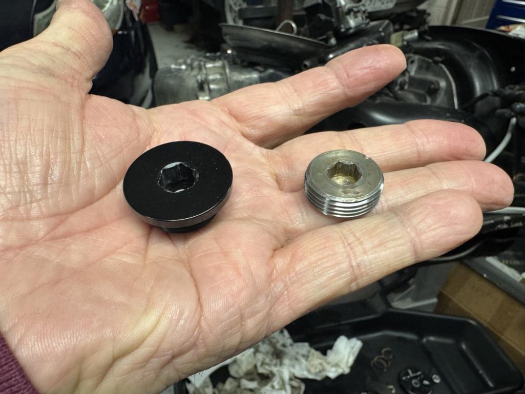
I cut the head off and the finished result is the same thickness as the original: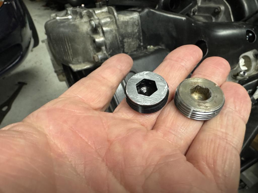
I wasn't sure what sealant to use, but someone had suggested Loctite 574, so I ordered a tube. Of course, I only found it in 50ml tubes and larger, so I now have plenty of extra....
I also ordered a cheap tap, which I cut down to clean the old sealant out of the threads the hole.
I tried a few different solvents and cleaners, but the tap was the only thing that worked to actually clean the threads. Yes, I know I could have removed the fan and ductwork off the front of the engine, but I was trying to minimize the amount of stuff to be removed and reinstalled later.
And, just to help my odds of sealing, I put the new plug in the refrigerator and put a heater on the engine.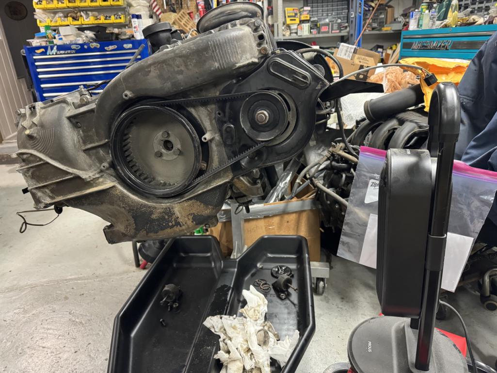
Note that the engine is tilted over. I also put a 2x6 under the front of the engine stand. This positioning helped keep that last little bit of remaining oil that never completely stops dripping from running forward into the threads.
After about 1/2 hour of heating/cooling, I used a q-tip to apply sealant to the hole threads and also applied some to the threads of the plug. I then screwed the plug in as tight as a I could without risking the remaining hex in the plug, so maybe 10-15 ft-lbs or so -- this is tighter than the original plug was, and the sealant should keep it stuck. But, just in case, I also staked the plug, like factory.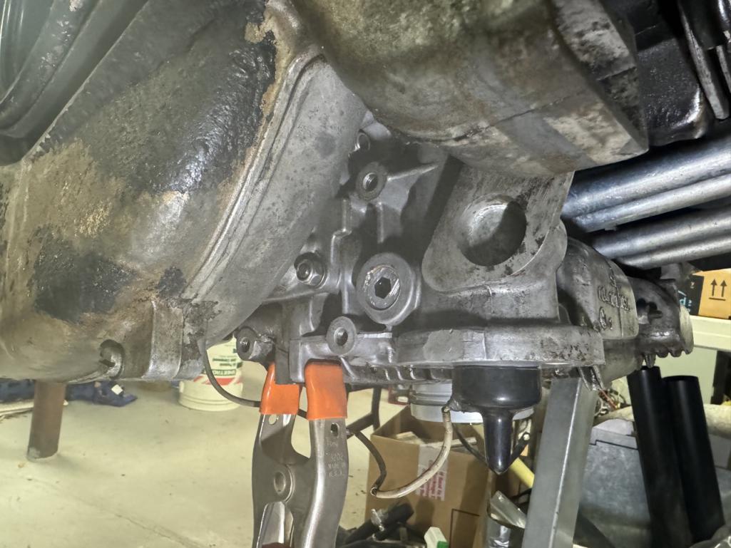
Hopefully, that's the end of that leak.
Posted by: bkrantz Jan 30 2024, 09:25 PM
Fingers coursed for you!
Posted by: BillC Feb 5 2024, 06:51 PM
And I'm just slowly chugging away on the engine. Still waiting for a few more parts to be delivered before I can wrap it all up.
Since the last update, I have:
- Changed oil filter
- Fixed another stripped hole
- Installed 123Ignition distributor and rough-timed it
- Installed coil and ignition wires
- Started installing vacuum hose kit from AA
- Tested and installed working AAR valve
- Tested and installed working Decel valve, making sure hoses are connected correctly.
- Installed intake runners and intake manifold, with new connecting hoses (and yes, I did remember to remove the paper towel plugs first).
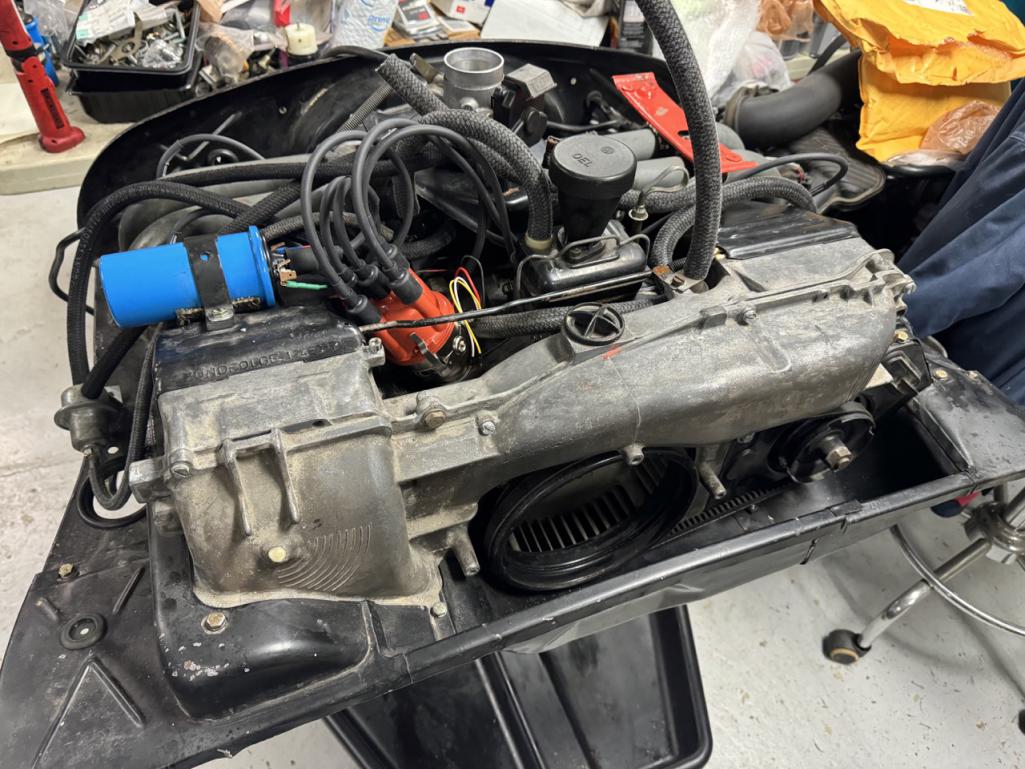
Out of curiosity, and because I wanted to try out this oil filter cutter I bought from a friend, I cut open the old filter.
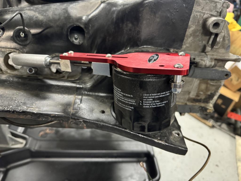
I was pleased to find no large chunks or shiny bits inside the filter. However, I did find plenty of black sludge at the bottom of the filter canister. I'm hoping it's just assembly lube and the previous owner simply didn't change the oil soon enough.
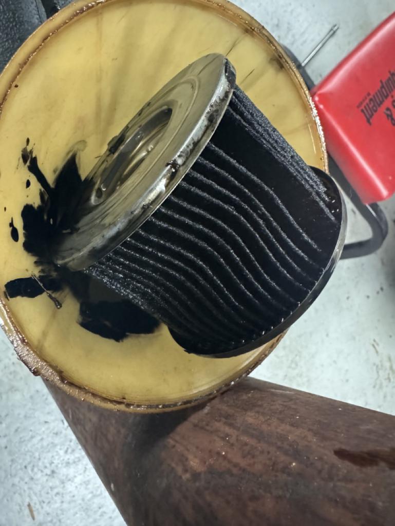
Once I (finally) get the car back on the road, I will change the oil early, just to help clear any remaining gunk out of the engine. The oil did look okay when I drained the engine three years ago.
Posted by: 930cabman Feb 6 2024, 02:43 PM
Keep your momentum going, soon you will be rolling down the highways
Posted by: BillC Feb 12 2024, 04:15 PM
Was able to get a little more work done on the engine this weekend. Here's what I did:
- Installed fuel rails and new fuel injectors & hoses.
- Installed remaining wiring harnesses from @http://www.914world.com/bbs2/index.php?showuser=104
- Added fuel pressure gauge.
- Installed thermostat pulley.
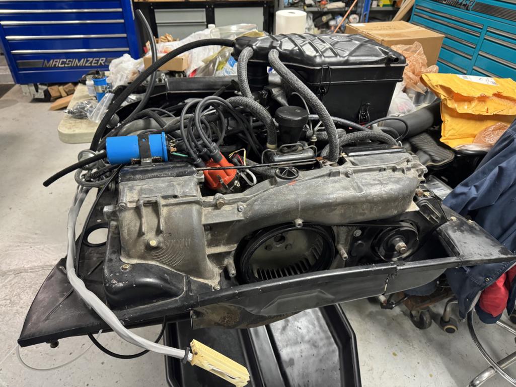
One hose from the AA vacuum hose kit was too short, but fortunately I had extra hose from a previous project.
Still waiting on thermostat and oil pressure relief valve, but they should arrive any moment. Once those are installed, then I need to get the engine compartment ready and I should be able to reinstall the engine.
Posted by: bkrantz Feb 12 2024, 08:47 PM
Did you seal the bolt for the thermostat pulley?
Posted by: BillC Feb 13 2024, 08:13 AM
Did you seal the bolt for the thermostat pulley?
Yup, small amount of sealant on the threads prior to screwing in the bolt.
Posted by: BillC Feb 17 2024, 07:10 PM
The last of the engine parts came in -- thermostat & related parts from Awesome Powdercoat, and the oil pressure relief valve from Tangerine Racing. Here's a pic of the thermostat installed: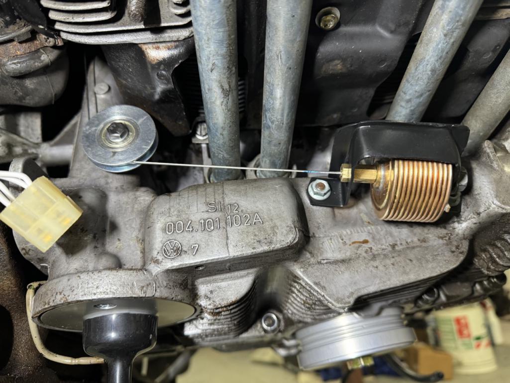
The thermostat itself from Awesome Powdercoat is a very nice piece. Unfortunately, his bracket needed quite a bit of finessing for everything to fit & line up correctly. And the pulley he sells is a storm door roller that seems to be a little smaller than the original -- I had to file the cable hole in the sheet metal aft about 3/16" to keep the cable from dragging.
Fortunately, the oil pressure relief valve went right in place with no issue, once I found the tool I made years ago for unscrewing the retaining bolt. No pics of that though, since there isn't anything to see once it's all in.
Posted by: BillC Mar 18 2024, 05:36 PM
Lots of other things going on, now that winter is ending, but I have made some progress on the 914.
Since my last update, I have been preparing the engine compartment so the engine can be reinstalled. So far, I have scraped out and replaced cracked seam sealer, treated more areas with rust converter, installed new seals around the engine tin opening and finished installing the stainless steel fuel lines.
Here are a couple of pics: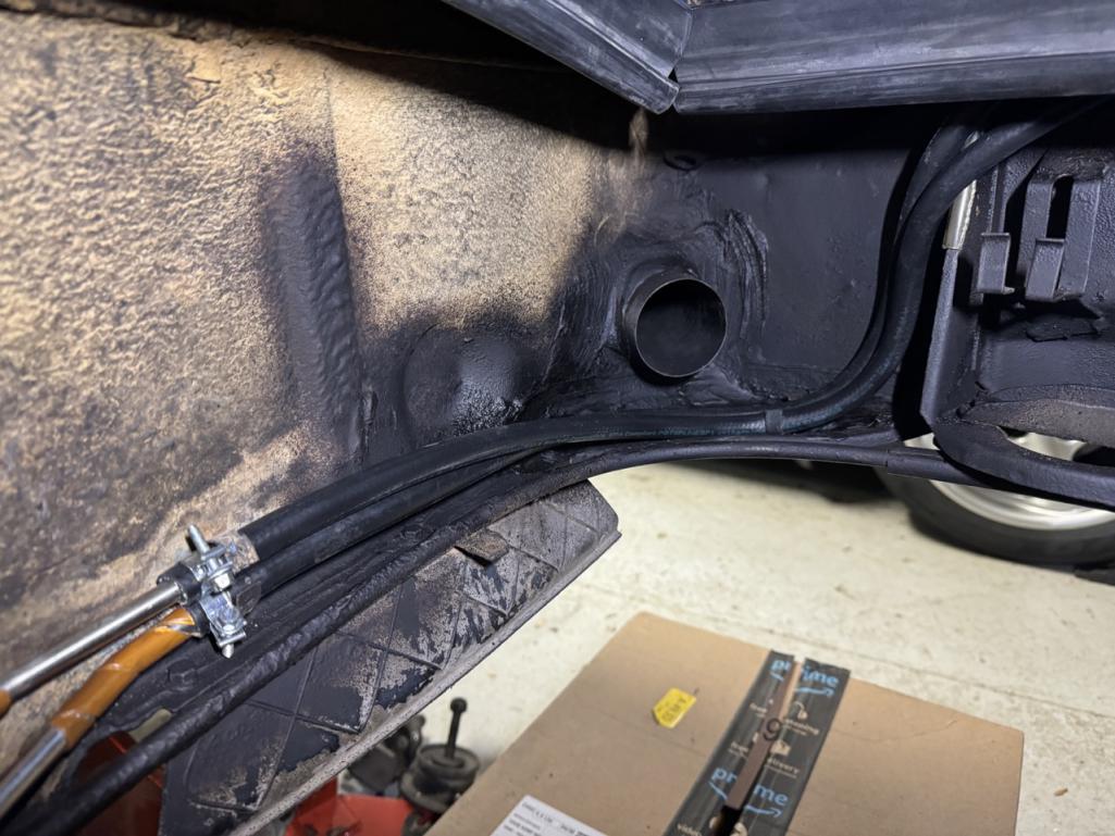
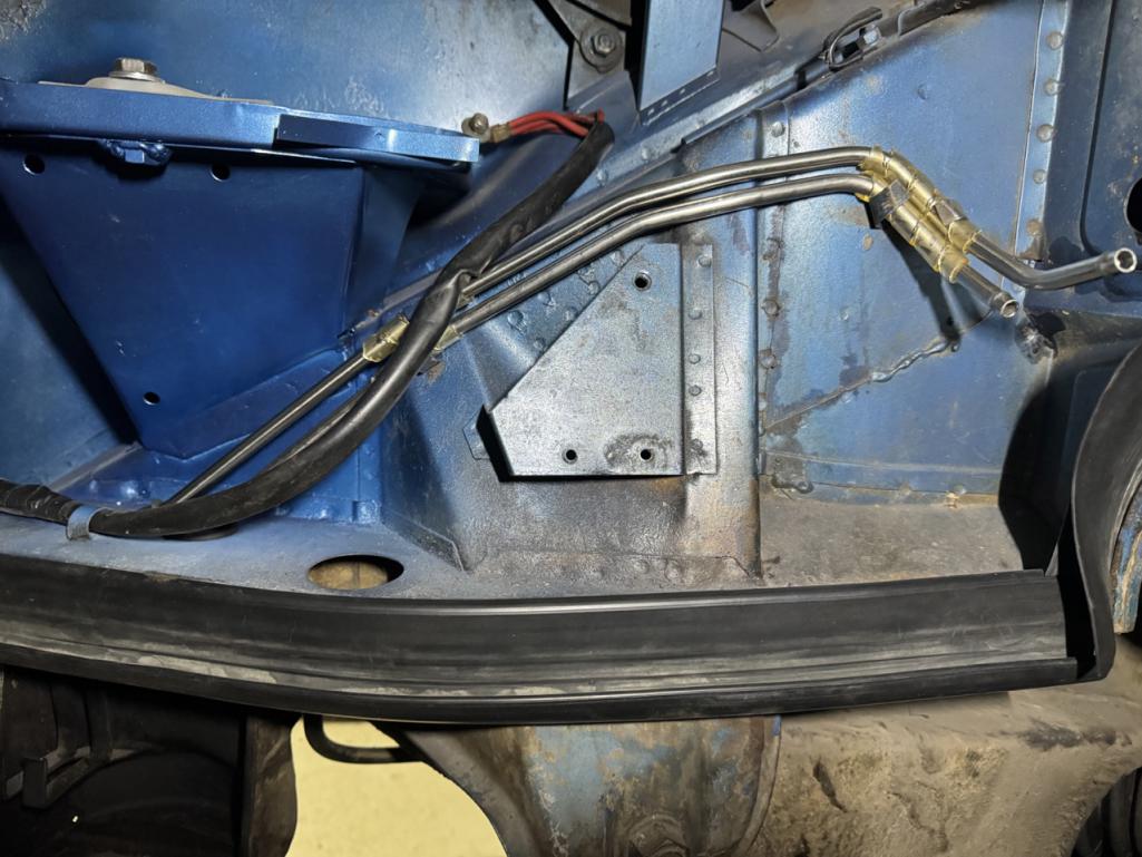
Posted by: windforfun Mar 18 2024, 06:04 PM
What rust converter did you use? POR-15?

Posted by: BillC Mar 18 2024, 06:43 PM
What rust converter did you use? POR-15?
POR-15 isn't a rust converter, it's a paint. It may seal rust from moisture, but it doesn't actually do anything to the rust (except stick to it). Plus, I've heard plenty of bad stories about POR-15 failures.
I'm using this:
It chemically converts rust to a different iron compound that is chemically inert as well as sealing the surface. There are other brands with the same action, this is what the FLAPS had on the shelf.
Posted by: windforfun Mar 18 2024, 07:36 PM
Ditto on that. So how does this stuff convert rust to a different compound? How does this stuff work better that POR-15? Just curious.
https://en.wikipedia.org/wiki/Corrosion
I remember now, it converts rust into what? Now I can't remember. Plutonium perhaps.
https://en.wikipedia.org/wiki/Rust_converter
Posted by: windforfun Mar 18 2024, 07:47 PM
See item # 4:
https://mechanicbase.com/reviews/best-rust-converter/
And Bob's your uncle ("Mission Impossible - Dead Reckoning" IIRC.)
Posted by: bkrantz Mar 18 2024, 10:17 PM
Nice work. You might want to miter the corners of the engine compartment seals so they will close up tightly when the engine is in place.
Posted by: barefoot Mar 19 2024, 12:24 PM
What rust converter did you use? POR-15?
POR-15 isn't a rust converter, it's a paint. It may seal rust from moisture, but it doesn't actually do anything to the rust (except stick to it). Plus, I've heard plenty of bad stories about POR-15 failures.
I'm using this:
It chemically converts rust to a different iron compound that is chemically inert as well as sealing the surface. There are other brands with the same action, this is what the FLAPS had on the shelf.
I'll second that, the Loctite stuff did the trick, turns the surface a dull black.
Barefoot
Posted by: 914_Tcup Mar 19 2024, 10:03 PM
I am so impressed by the way you documented your work...I (we) owe you for this!
Thank You.
You showed me the amount of misery and pleasure I have ahead, but knowing there are these different methods in solving the problems gives me hope in restoring my car.
Do you have a post somewhere about your "Boxster"? I am looking at purchasing one, but want to see what others who wrench on them think. ![popcorn[1].gif](style_emoticons/default/popcorn[1].gif)
Posted by: BillC Mar 20 2024, 07:34 AM
You might want to miter the corners of the engine compartment seals so they will close up tightly when the engine is in place.
That's a good suggestion. However, I think I'll wait until after the engine is in, just so I don't accidentally trim too much off.
IIRC, the factory actually installed hog rings to keep the corners closed.
Do you have a post somewhere about your "Boxster"? I am looking at purchasing one, but want to see what others who wrench on them think.
The Boxster is a '99 that I bought as a failed restoration and turned into a Spec Boxster race car. The guy I bought the car from bought it from an estate sale, but quickly realized it needed more work than was financially effective -- the roof was torn, the a/c shot, clutch slipped, old brakes & bearings, mice had moved into the center console, etc. This was perfect for a race car donor, since it was all stuff that would be removed or replaced in the conversion process.
Being a newer car, it is a little more complicated to work on (as a street car) than a 914. But the best part is virtually no rust -- the factory rust protection was greatly improved over the intervening 26 years. As a race car, though, it is fairly simple to work on, since most of the complicated stuff (a/c, heat, folding roof, interior, radio, etc.) has been removed.
Sorry, no post about the car, though. However, I did write a 2-part article about the conversion a couple of years ago for the local PCA chapter magazine, Der Vorganger. If anyone is really interested, I can see about copy/pasting it here.
Posted by: BillC Mar 24 2024, 04:06 PM
In today's episode of "Trying to work on the 914 while life gets in the way", I finished wiring up the third brake light. I wanted to make sure I could remove the engine lid without having to remove all the wiring, and also to connect it to the car without modifying the factory harness.
First step was installing a plug at the base of the engine lid, so I can unplug the wires if the lid has to come out. I bought a Deutsch connector kit and crimp tool on amazon, and was pleasantly surprised at how well the crimp tool works.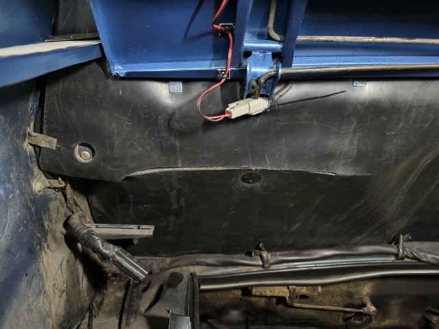
For the wiring, I bought a roll of dual-conductor 16-ga wire in a black sheath, and ran it under the firewall padding and along the factory harness. Then, I used these piggyback connectors to tie into the left, rear brake light: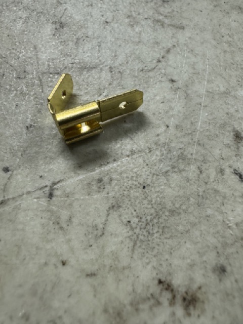
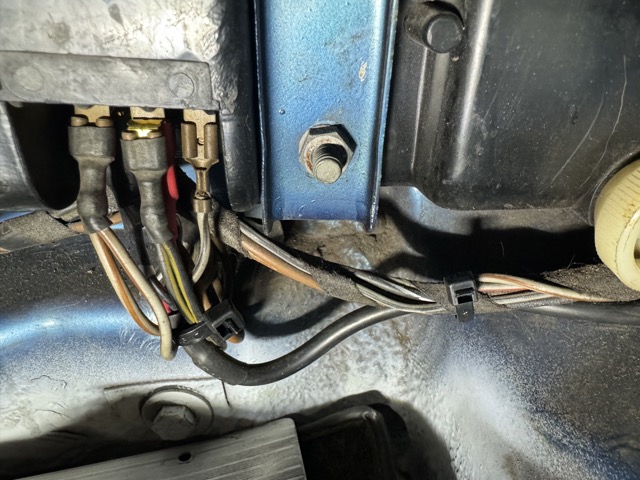
I made sure to heatshrink some insulation over the piggybacks, just to help keep things from shorting.
Finally, here's a pic of the 3rd light lit up: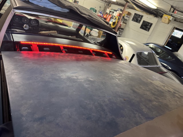
The trunk lid isn't closed, which is why it looks a little funky.
Posted by: FlacaProductions Mar 24 2024, 06:52 PM
Worthwhile addition - nice work.
Posted by: bkrantz Mar 24 2024, 08:28 PM
Very cool.
Powered by Invision Power Board (http://www.invisionboard.com)
© Invision Power Services (http://www.invisionpower.com)