Printable Version of Topic
Click here to view this topic in its original format
914World.com _ 914World Garage _ Re-Conversion of a '70 914
Posted by: 76-914 Jun 28 2020, 08:36 PM
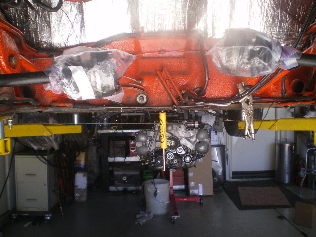
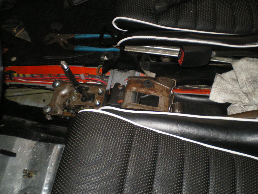
The engine is sold. I'll soon have a very fresh 901 w/ an "H" gear for sale as well as some other goodies soon for those planning an SBC conversion. I couldn't do much with this sitting in my garage as it already is stuffed to the max. Therefor I felt it somewhat necessary to sell this before commencing with the re-conversion. I've been silently (yeh, I know; me silent) working in the background for a few months fabricating some items that will be needed. I'll do my best to document things a bit more accurately than the previous conversion. Once again I'll be using the Subaru 6 and Subaru transmission. I've had tremendous success with this platform so I might as well repeat myself. So sit back, bear with me and watch as I stumble along and occasionally embarrass myself. Mistakes are an integral part of my journey. 
Attached image(s)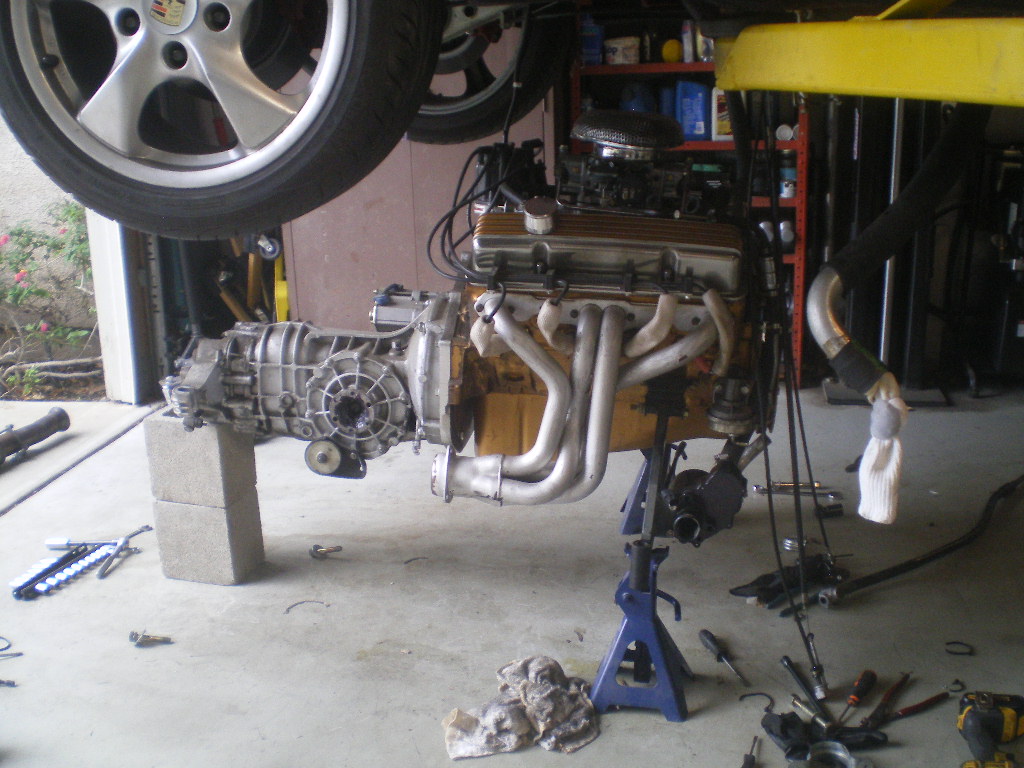
Posted by: tygaboy Jun 28 2020, 09:31 PM
Yaaaa! Can't wait to see this one come (back) together!
Let me know if there's anything I can do to help. I'd love to contribute to one of your builds.
Posted by: EdwardBlume Jun 28 2020, 09:35 PM
Love those Boxster rims. 70 was a good year. I know a guy with a 0mi 3.0 if you're into that kind of thing...
Have fun!
Posted by: 76-914 Jun 30 2020, 04:52 PM

Yaaaa! Can't wait to see this one come (back) together!
Let me know if there's anything I can do to help. I'd love to contribute to one of your builds.
Thx Chris but your work is too nice for my "hack" builds.
 I might; I'll let you know if so. Thx.
Posted by: 76-914 Jun 30 2020, 04:53 PM
Love those Boxster rims. 70 was a good year. I know a guy with a 0mi 3.0 if you're into that kind of thing...
Have fun!
That's exactly what I'm installing. A 3.0.
Posted by: 76-914 Jun 30 2020, 05:44 PM
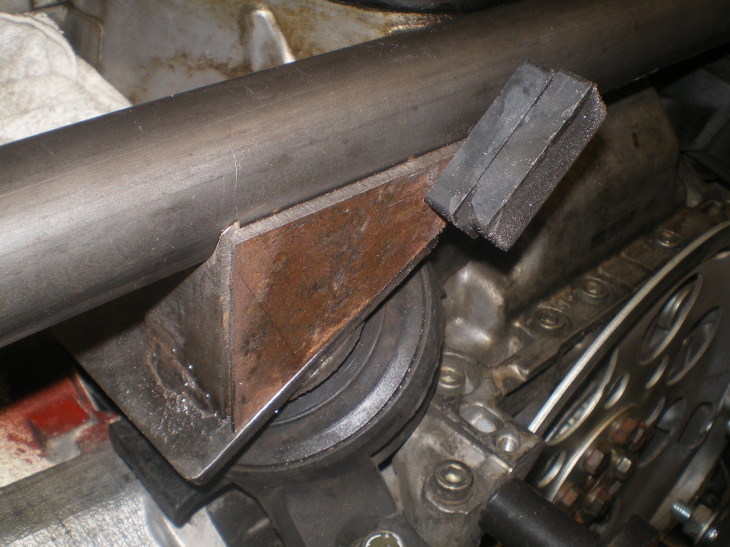
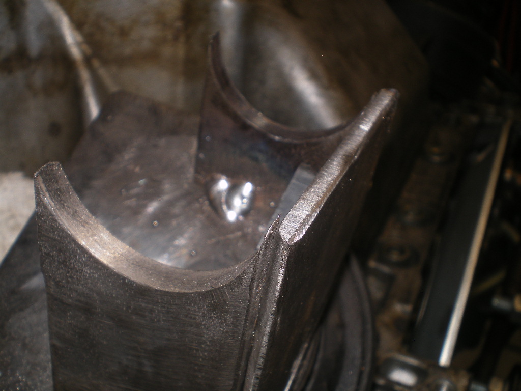
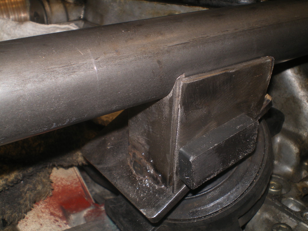
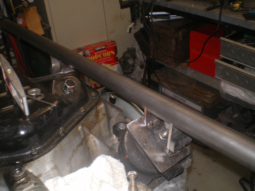
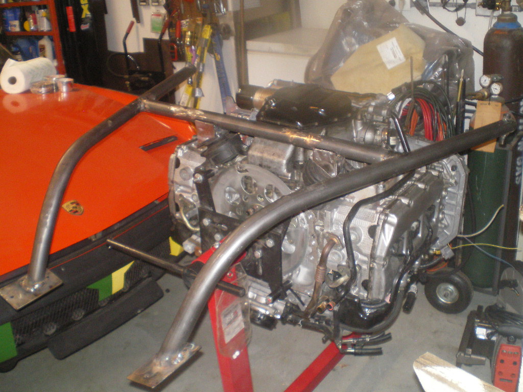
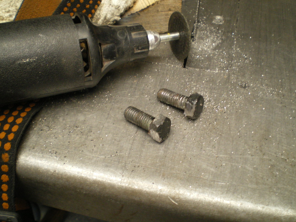
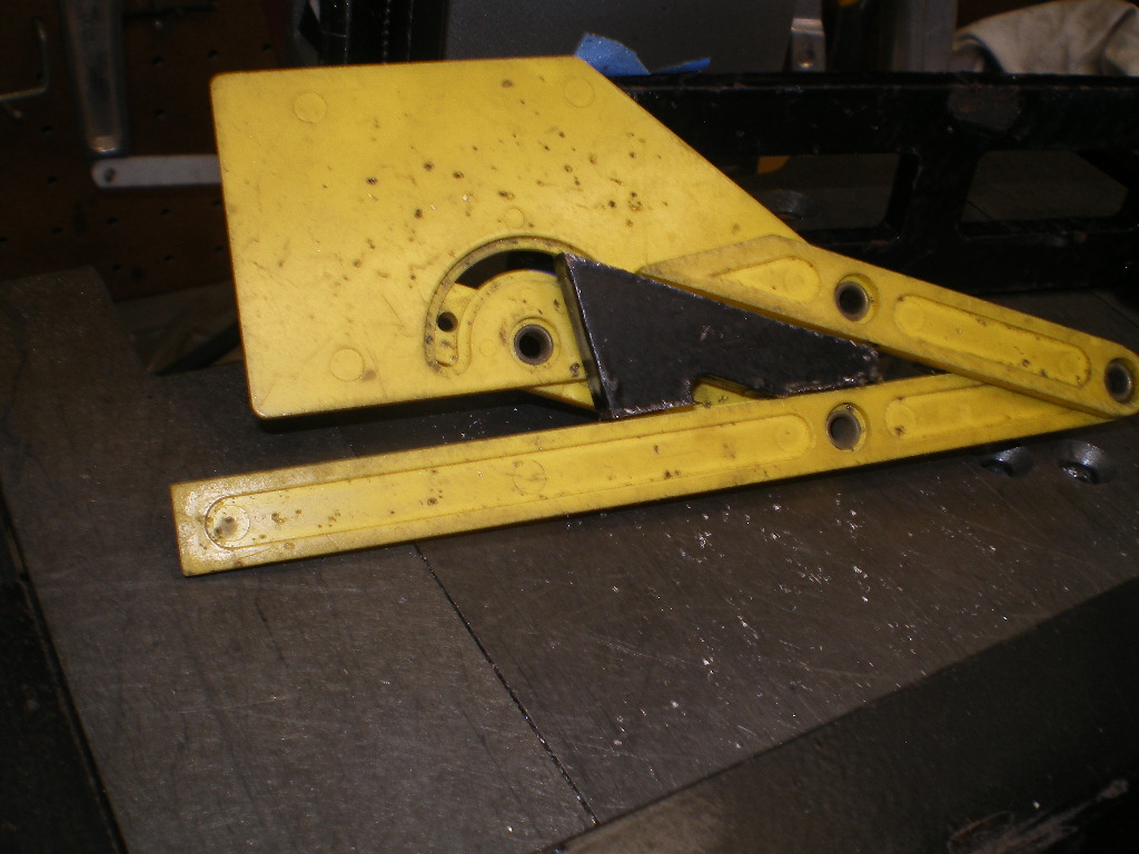
I've seen several requests for cradles in the past few years and that's not including the Facebook group. So I thought this time I would take it step by step to show that even a novice can build one. The process is simple so don't be intimidated. Minimal skills are required.If you can't weld, no sweat. You can pay a mobile welder to weld it up and you can do everything else yourself. You will need a drill press, a metal cutting bandsaw or chop saw, a $99 Harbor Freight tube bender and tubing notcher, assortment of drill bits and a couple of hole saws. Granted the tube bender and tubing notcher aren't tools you'd use again but you can sell them quickly to another member who wants to build one. I built my last one out of desperation. I'd waited 3 months for Ian of ColdWater to make another run and decided I'd give it a shot and if that didn't workout I'd wait till he finally got around to it. That was over 6 years ago and no ones brought any to market yet. I'll re-use many of the bolts from the OEM motor mounts, some scrap and some new metal. I'll quit yaking now and start hacking.
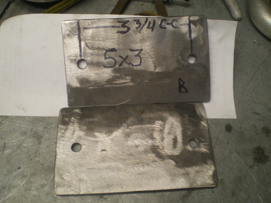
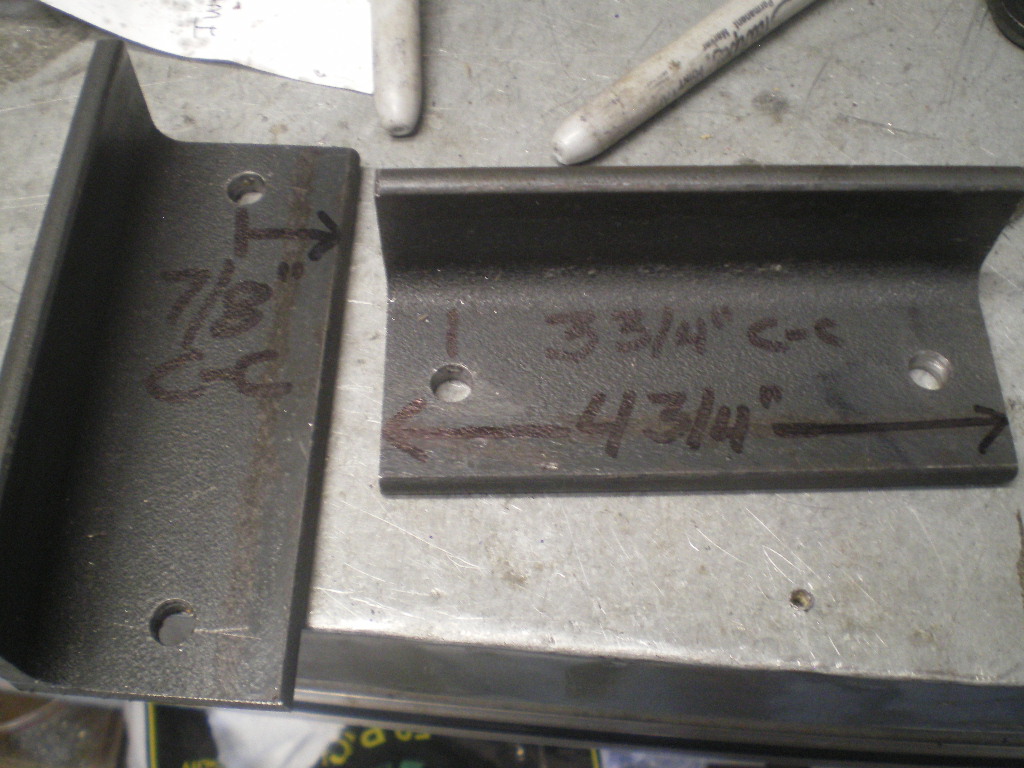
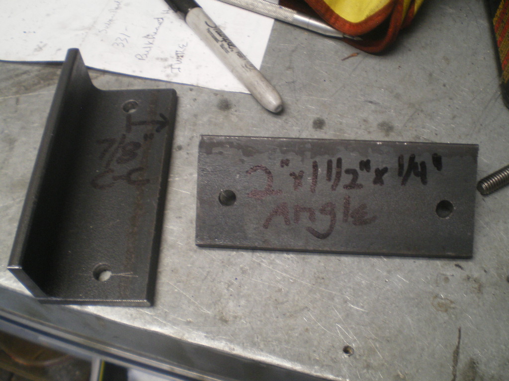
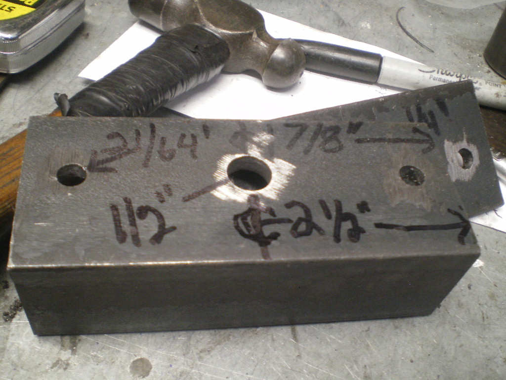
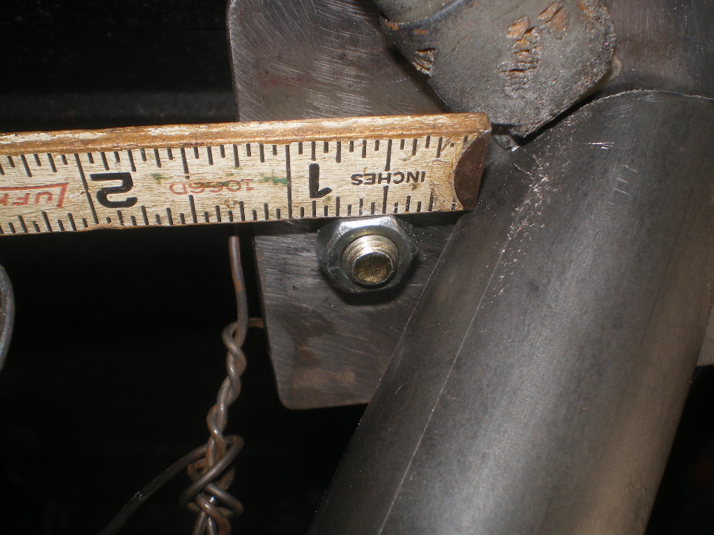
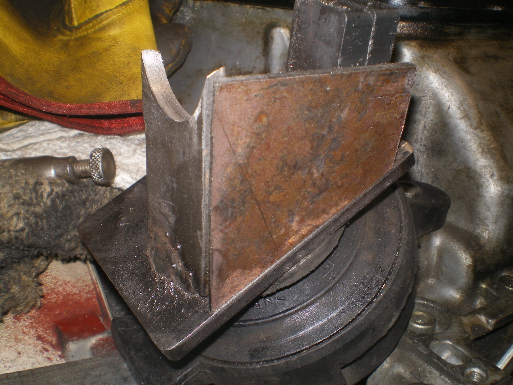
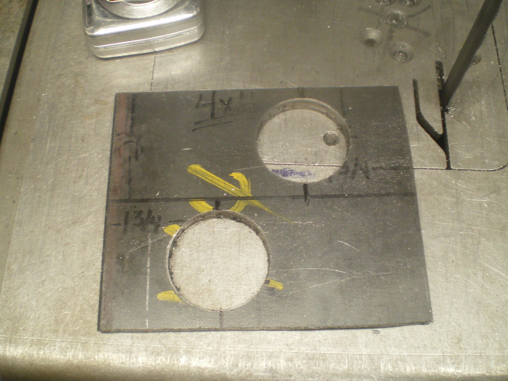
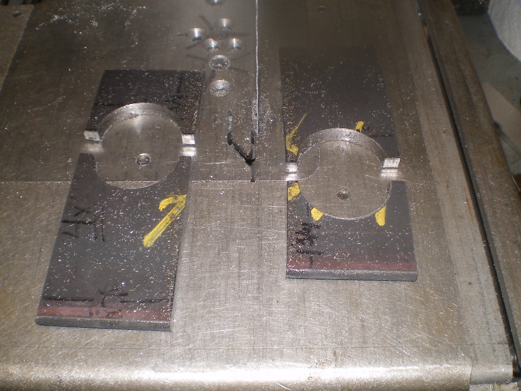
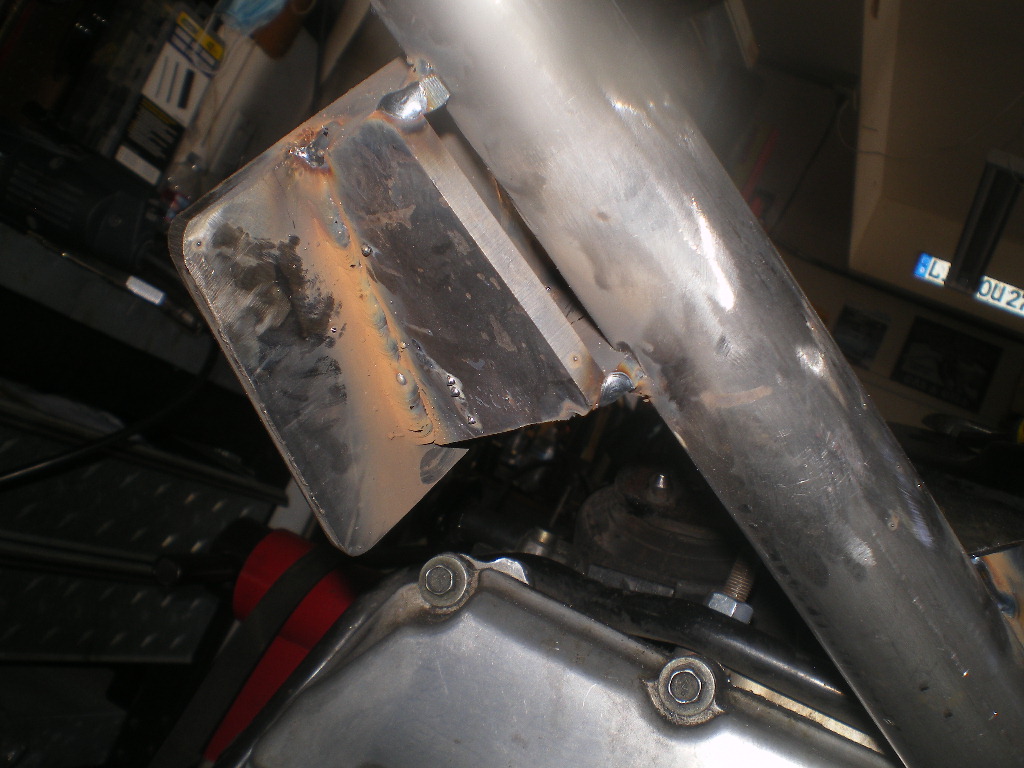
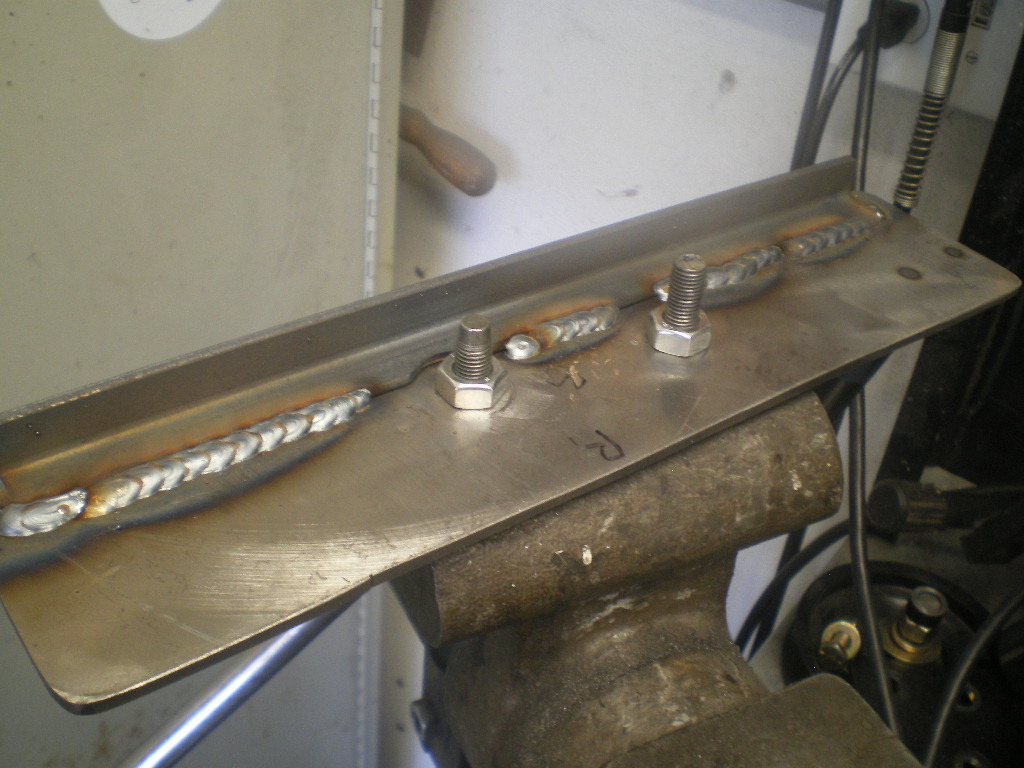
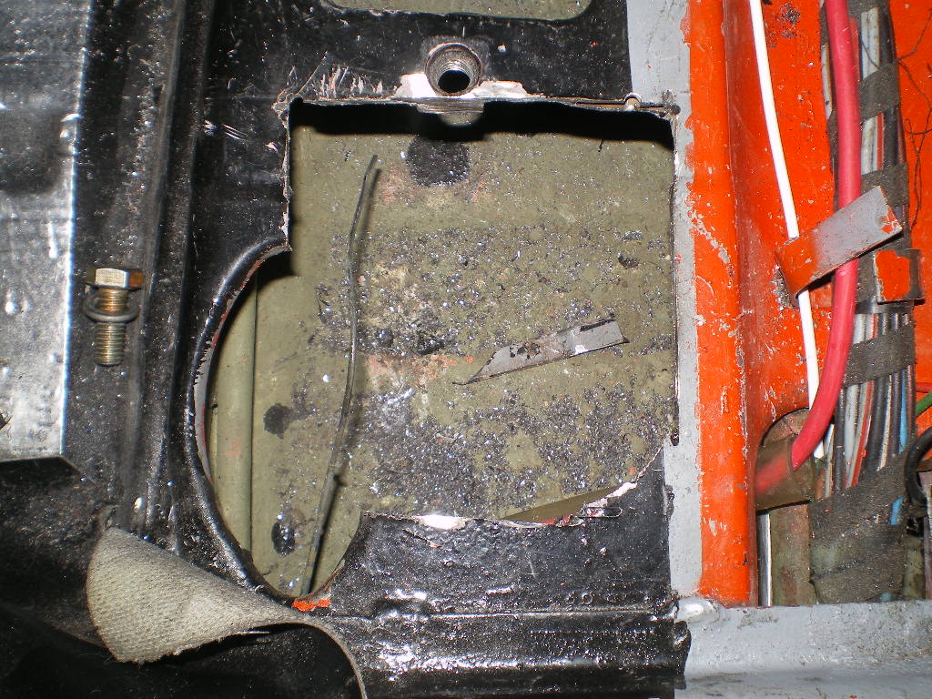
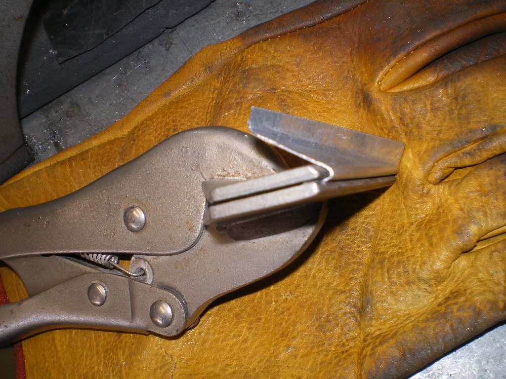
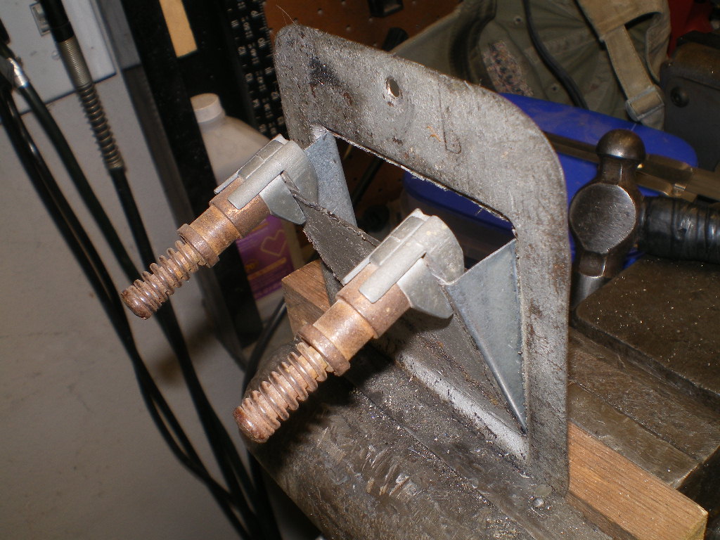
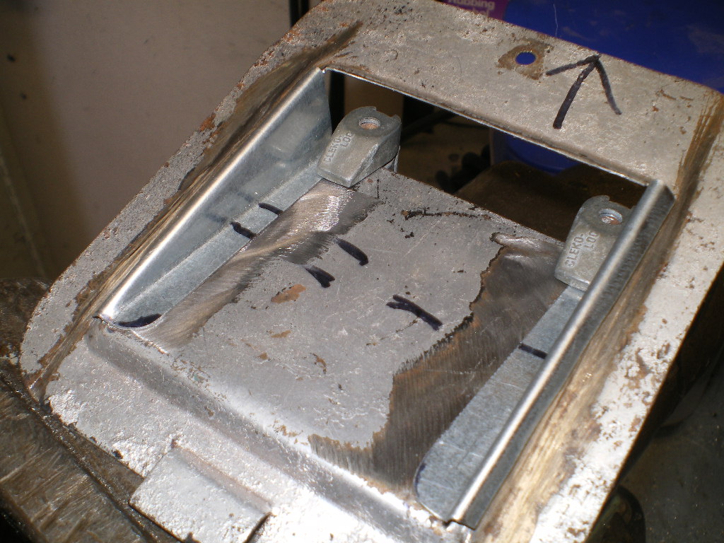
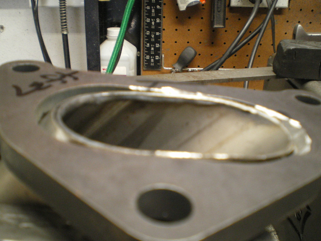
First your going to make some plates that will attach to the original mounting points on your 914. 2ea- 3"x5"x 3/16" plates and 2ea- 2"x 1.5""x 1/4" angle iron 5" long. There are a few pic's of the angle in order to show all the dimensions. If I forgot a dimension, LMK. NOTE: I just noticed in the 4th pic I listed two dimensions for the center of the 1/2" hole; 2 1/2" is correct. The 1 7/8" is a brain fart. 
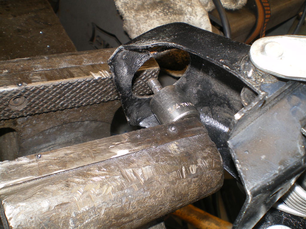
After you've completed these pieces pieces mount them in place as shown below. I'm re-using the existing nuts, bolts and washers. 


To be continued............
Posted by: flmont Jun 30 2020, 07:02 PM
What are u thinking price wise on that 901 , Thanks Frank
Posted by: 76-914 Jun 30 2020, 07:25 PM
What are u thinking price wise on that 901 , Thanks Frank
For you, Frank $600. If I list it $900 for putting up with the "Tire Kickers and Low Ballers". It shifts like a dream. No leaks or squeaks.No whines or grinds. No popping out of gear either. How's that conversion coming along. I'd like to see some pic's of what your doing.
Posted by: flmont Jun 30 2020, 07:36 PM
Sold..! TY
Posted by: flmont Jun 30 2020, 07:40 PM
its still the same I did buy 914forme's cradle / bracket,So I'am hoping to fit it over 4 th of july weekend,..I'am SO ready to install everything and fire it up I'am just so busy, but things are slowing down so I can have my weekends back very soon !
Posted by: flmont Jun 30 2020, 07:44 PM
I do need to read ChrisH,..posting on the heater core upgrade he did with a mustang box I think,.then I can install fuel tank ,then wiring !! its all ready just need time to assemble !
Posted by: 76-914 Jun 30 2020, 08:05 PM
Sold..! TY
PM sent
Posted by: 76-914 Jul 3 2020, 06:11 PM
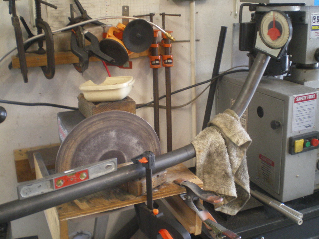
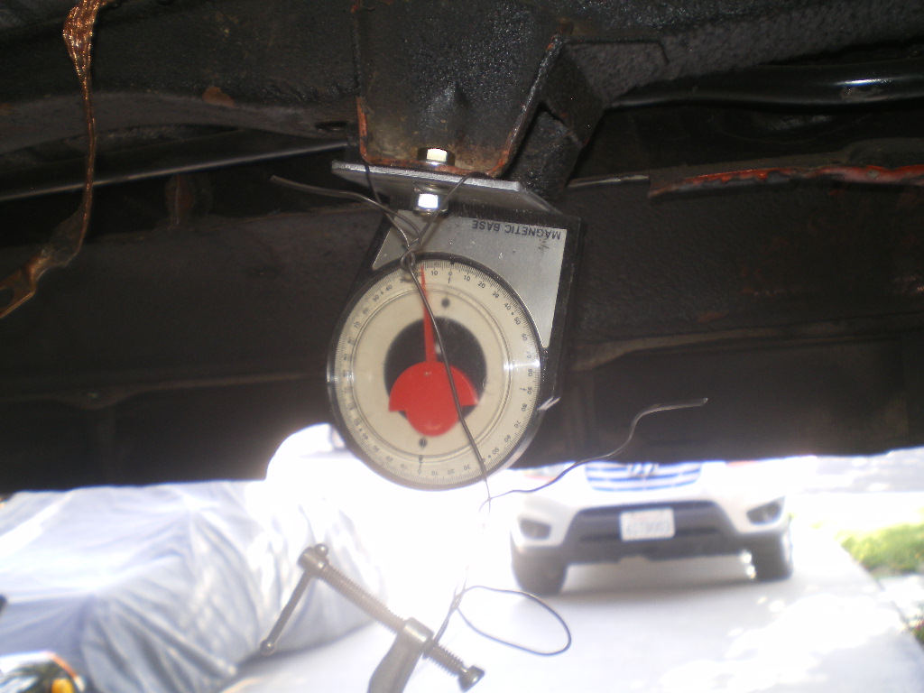
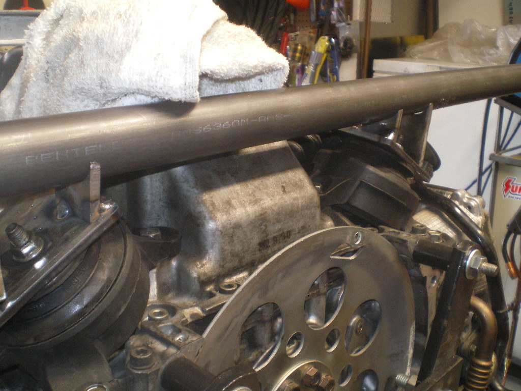
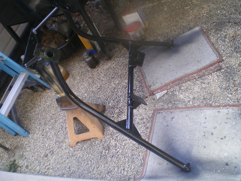
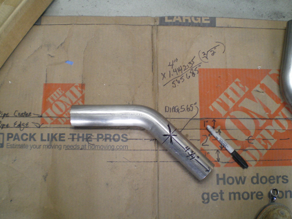
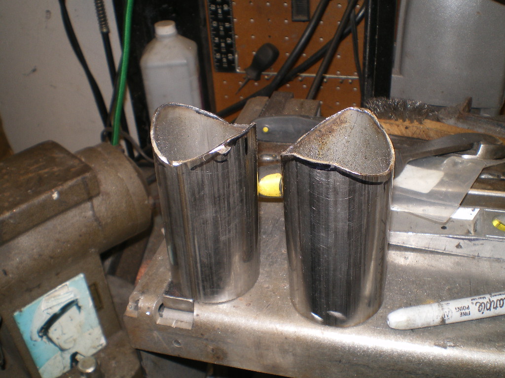
OK, back on track. If you plan to use 4130 chromoly it is sold in 12ft lengths. My 1st cradle I purchased 10ft and had about 4" left over. Thats cutting it too close so this time I sprung for the complete length. 1.5"x 12' .095 tube. Here is a pic of the cheap HF bender I use. $99 on sale.
Cut one piece 90" long then cut that in half giving you 2 - 45" pieces. Put the left over piece to the side for now. From one end of each pipe place a mark 22" down. This is your 1st bend point. Place the mark in the center of the bender with the rollers in the #1 pegs and give it several pumps until you see it begin to bend. It has a lot of bend back but after a few bends you'll know how many strokes to bend it. Look at the pics below and you will see how little deflection there is after the first few bends. Slowly work this area then move the pegs to the #2 position and repeat this process until you get the desired arc. Be sure to check your bend often against the graph shown. Those are 1" squares so you can duplicate it easily. 
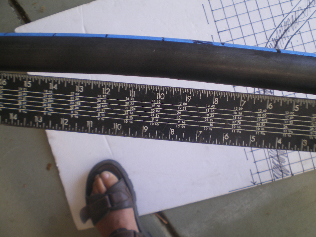
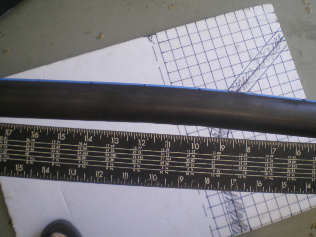
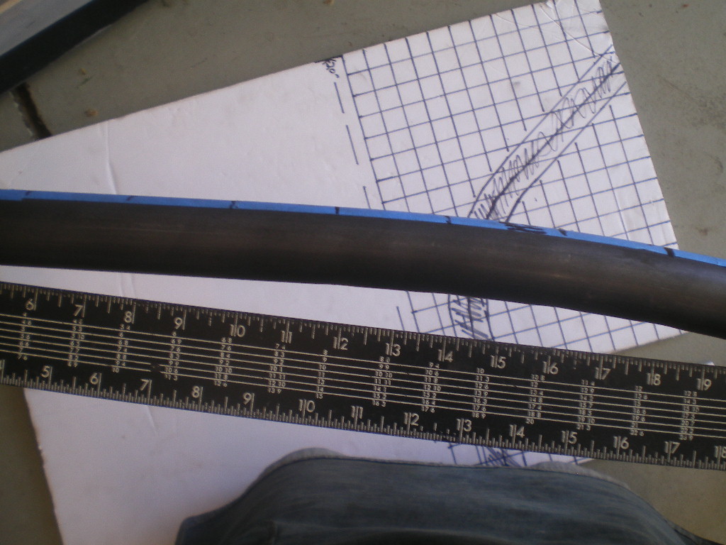
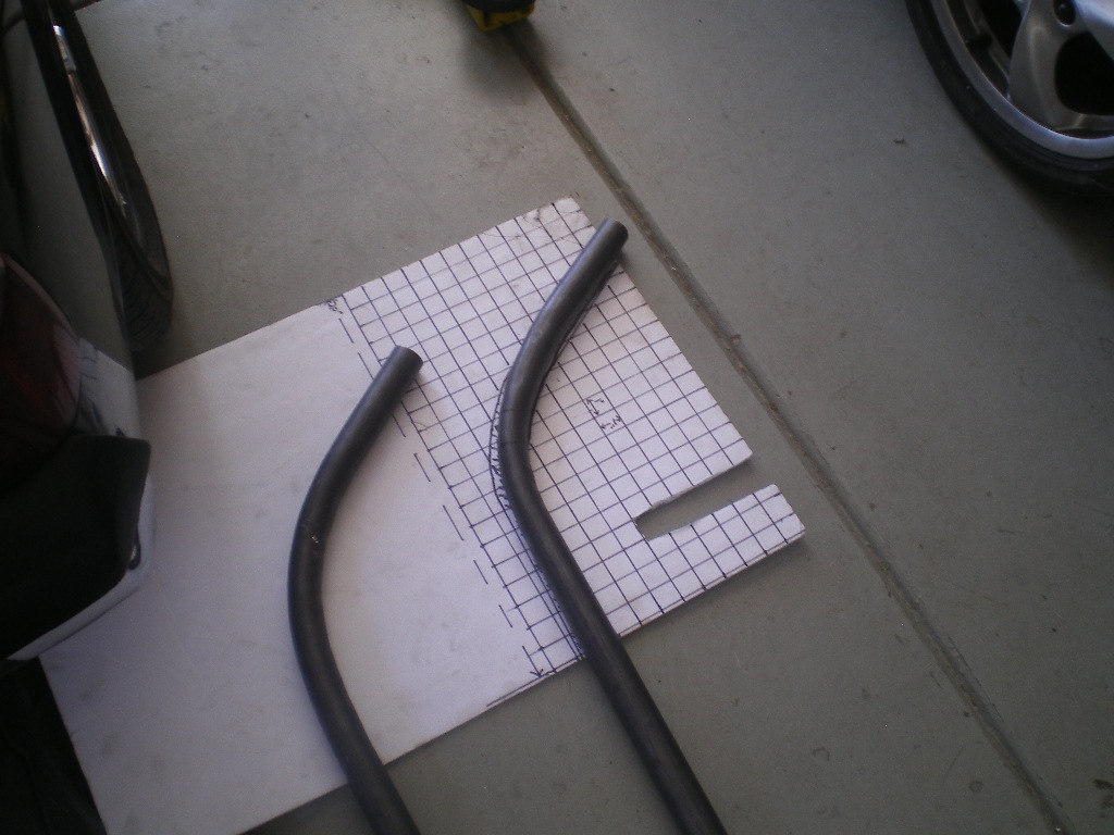
You want to leave the last 12" of the tube straight. So your only working/bending about a 12"-14" span of the tube. You will be trimming a few inches off each end for the final fit so you only need to establish the arc close to what is shown.
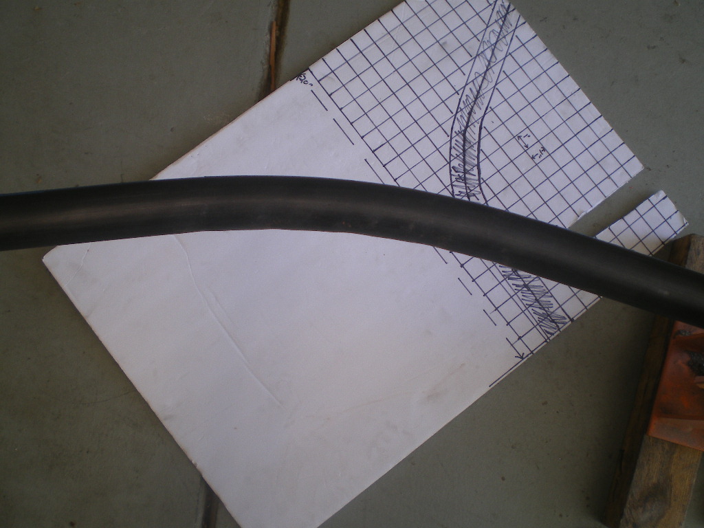
After the bend is complete we want to end up with a distance of 40" or greater between the ends. See below.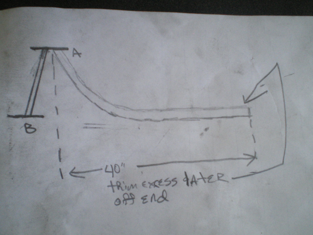
Once you've got these 2 pieces done you can move on to fitting them to the hangers.
Posted by: tygaboy Jul 3 2020, 06:53 PM
METAL!!!! 
So cool that you're documenting things that others will find useful. (Unlike some of us!  )
)
Great stuff! Thanks Kent.
Posted by: 76-914 Jul 3 2020, 07:24 PM
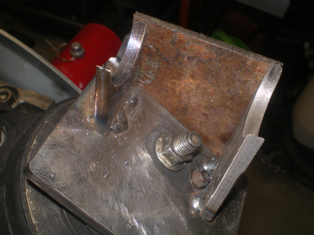
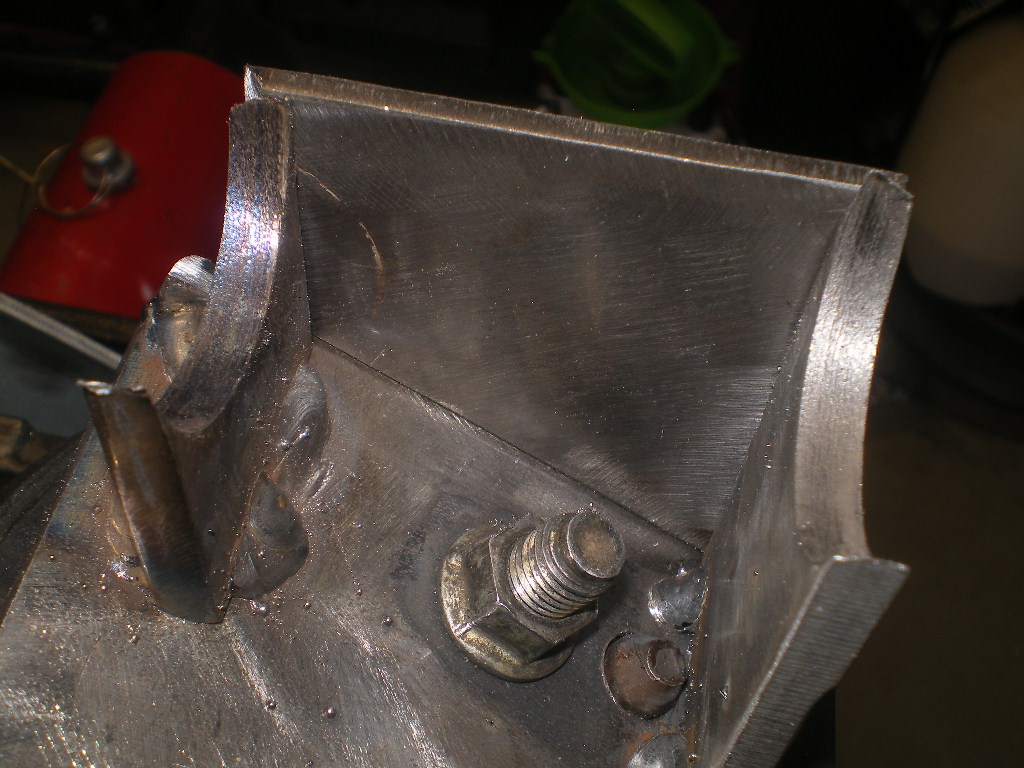
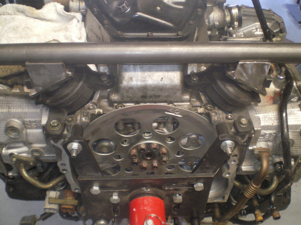
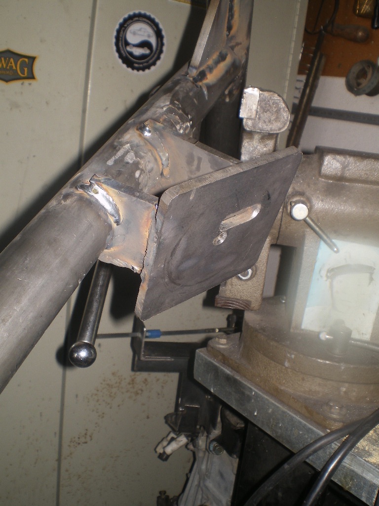
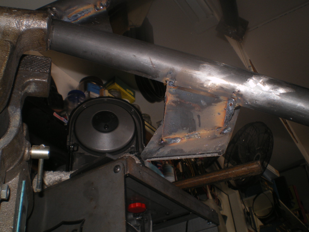
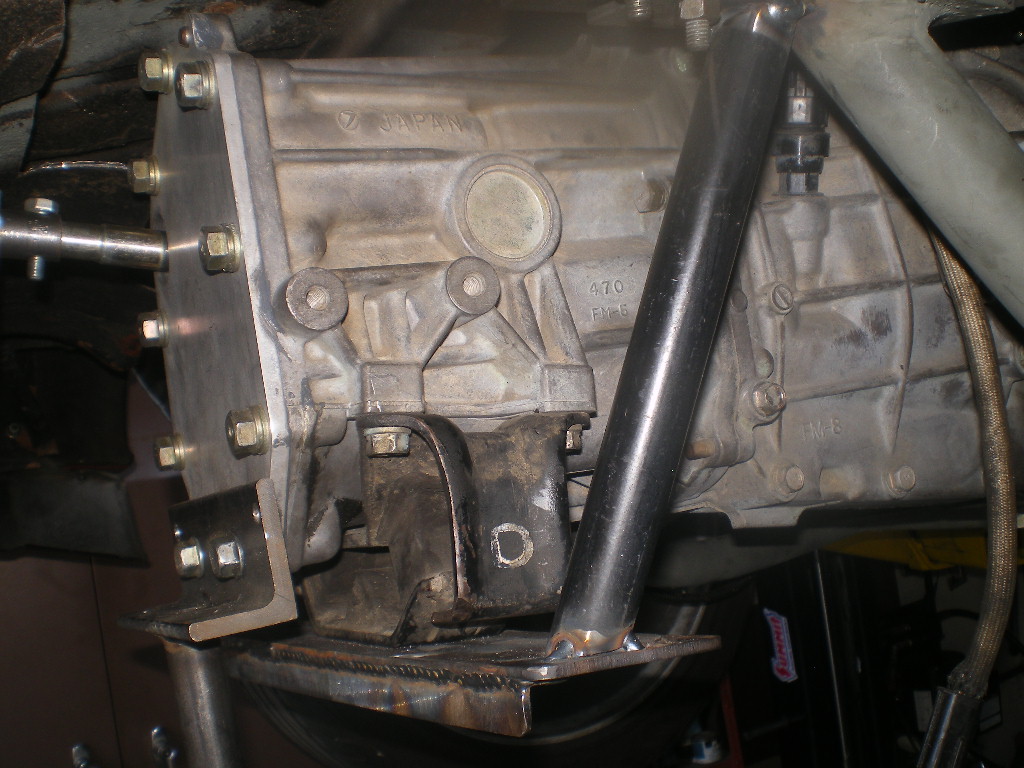
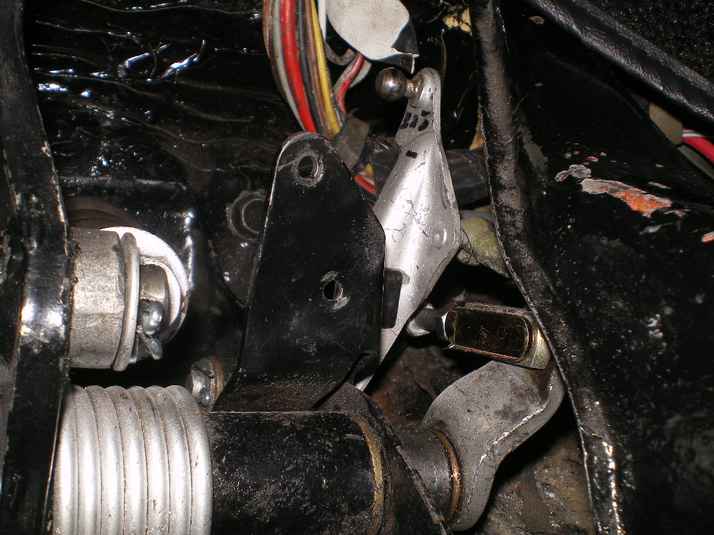
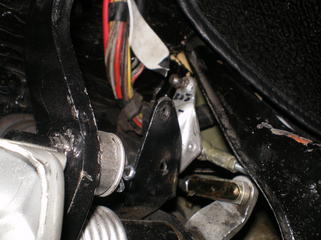
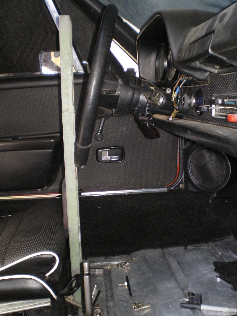
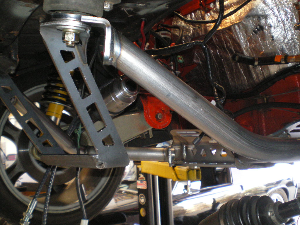
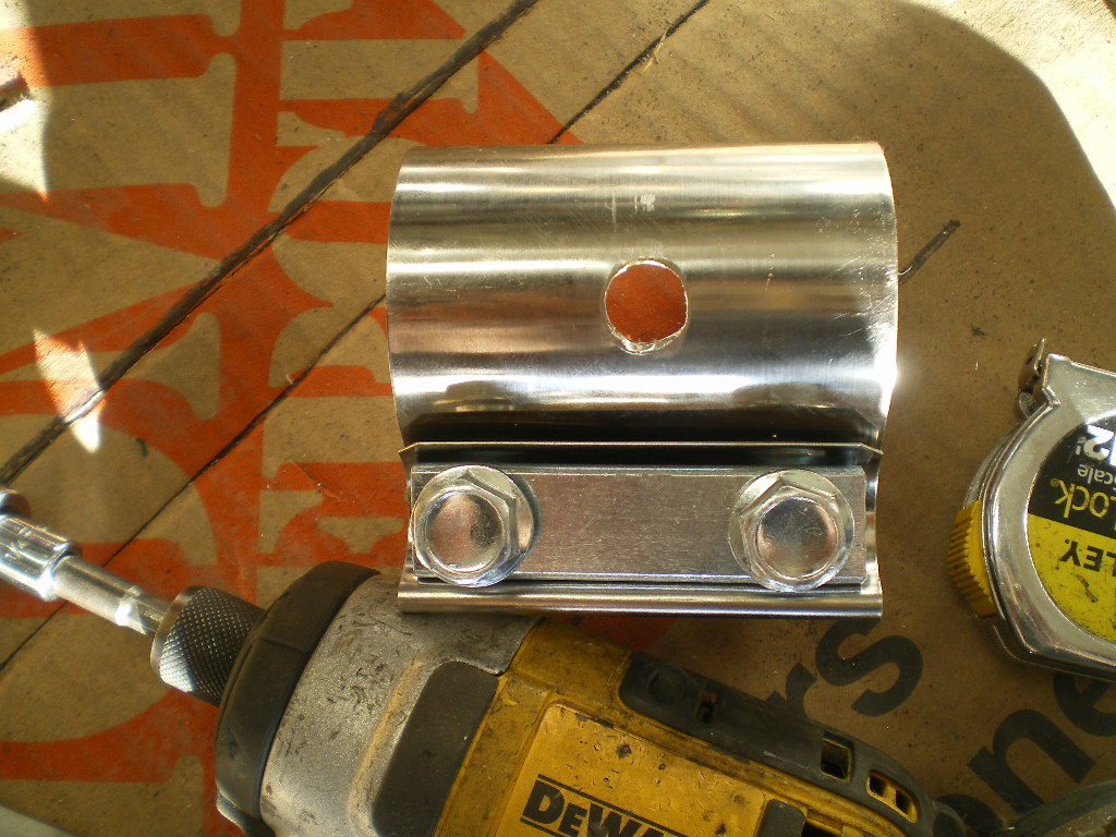
Go ahead and remove your old hardware from the front and rear attach points. Save the 5/16" & 1/2" nuts and bolts. Attach the 2- 3"x5" pieces to the former transmission mounts and the 2- 2"x1.5" angle pieces to the former engine mounts.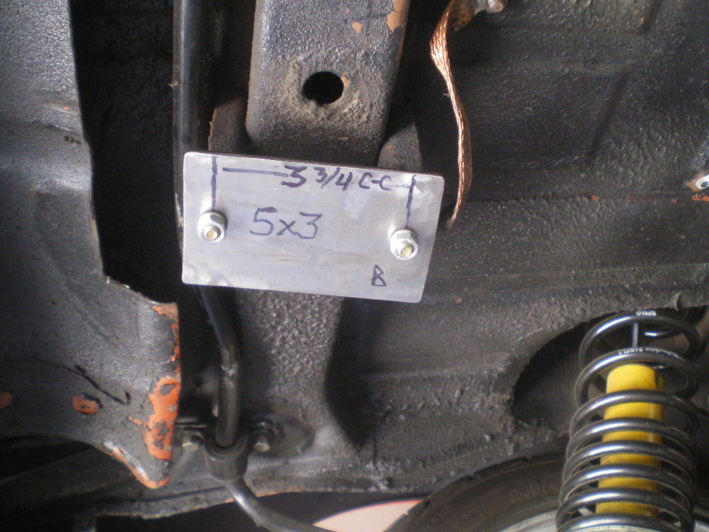
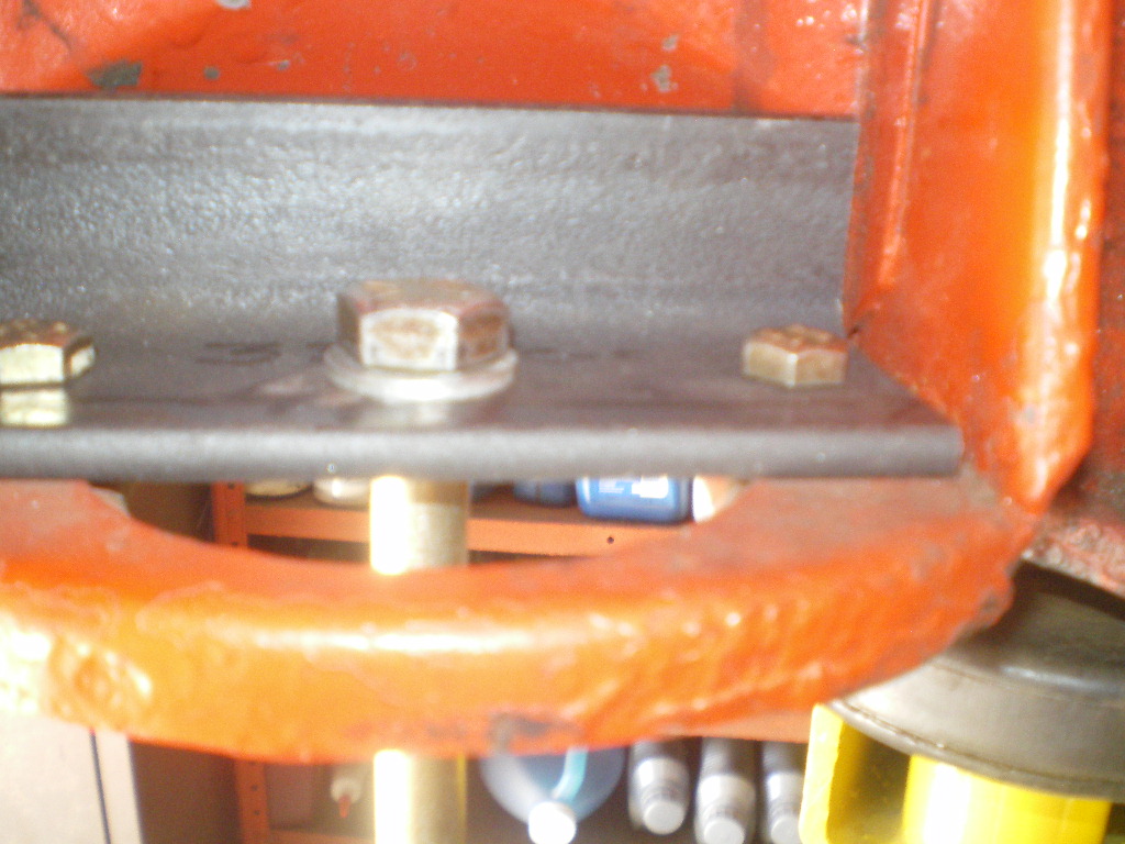
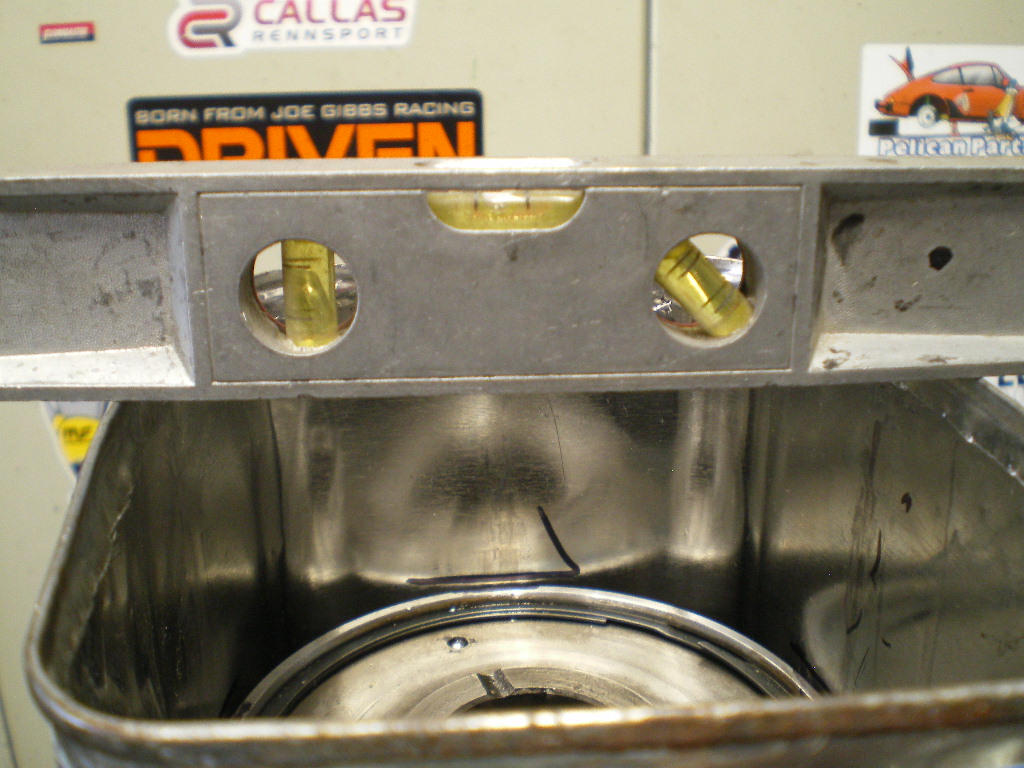
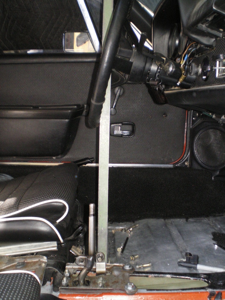
If you work by yourself you'll need to hang the runners in place. This can be trying to say the least. Several times my wife came out to the garage to see who I was yelling at. If you have a helper then this will be simple. The car will need to be level front to rear and left to right. I got lucky here because my lift is square to the floor. In the pic below you can get an idea of how I hung the runners with bailing wire. However you hang it is good. The objective is to center up length wise with the bolt hole of the front hanger and the center of the 3"x5" rear plate. 
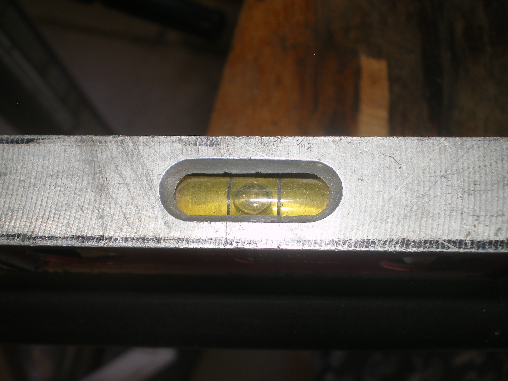
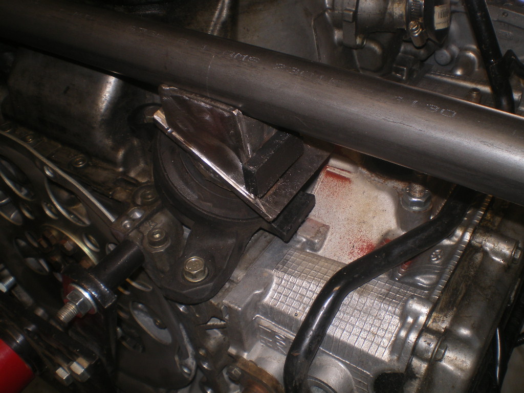
Once it's is secure be sure the section past or to the rear of the arc is perpendicular or 90 deg to the floor and that the long end is level or parallel to the floor. Ultimately the top of the tube should be 1" below the bottom of the angle iron bracket or 1.5" to the center of the tube. This is somewhat important. You may find you need to cut that angle piece twice in order to raise the back end enough to get it level while maintaining the 1" gap mentioned above and keeping the length level. Now is the time to mark the compound angle that will be trimmed off the top end. The 1st cradle I used a marks-a-lot but found the hacksaw blade to be much more accurate in transferring the mark because the blade could be held flush against both sides of the tape roll. Hold the roll flush against the plate. I needed to stretch the roll into an oval to work around the protruding bolts.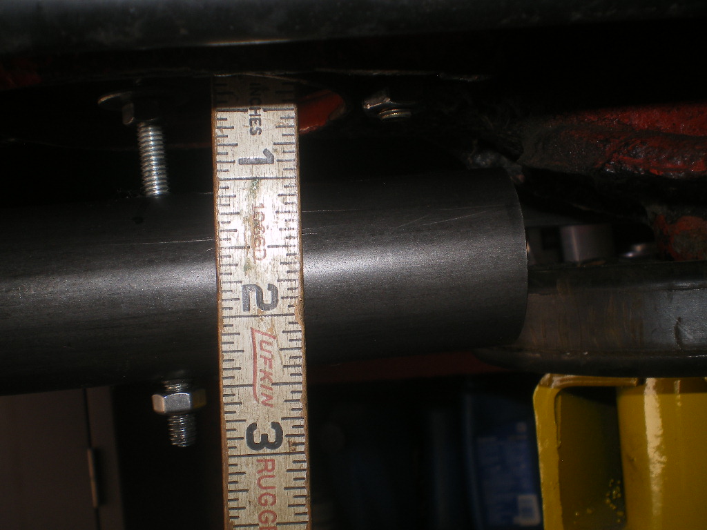
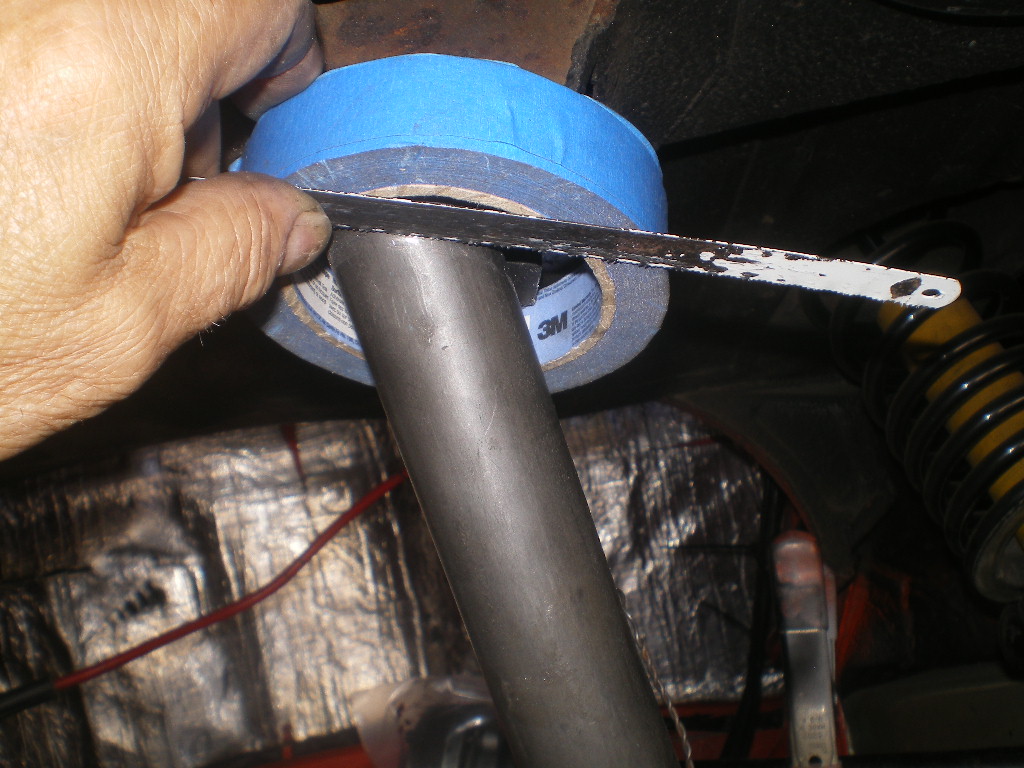
Once you've got a good mark it's time to cut it. I used an angle grinder with a thin blade to cut. I tried with my bandsaw but alas I couldn't hold it square with the compound angle. You will end up with a cutoff piece that looks something like this. I dressed the ends with a 12" sanding wheel but a file will work too.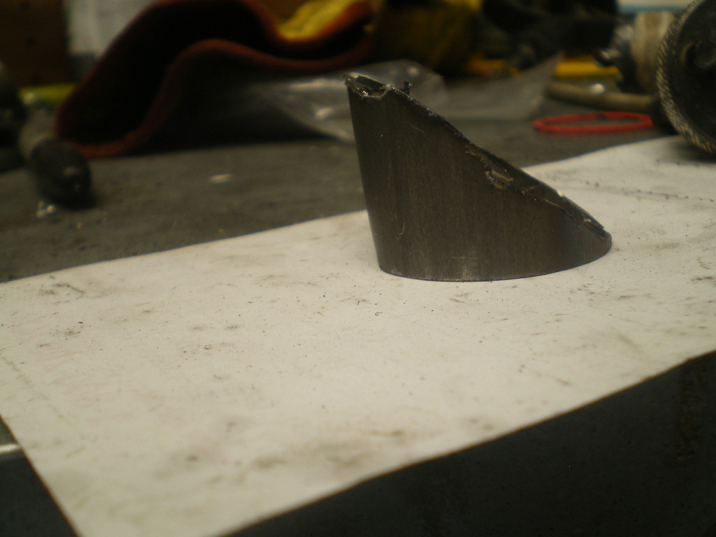
Edit: Don't know how this pic ended up here. I noticed this on my last build. Somehow the file gets corrupted when loading them. I've even gone back and deleted all of the pics yet one remained in the post although it doesn't show up as an attachment on the list of pics selected. Oh well. just ignore that one.
Attached image(s)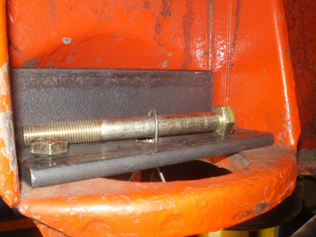
Posted by: 76-914 Jul 3 2020, 08:08 PM
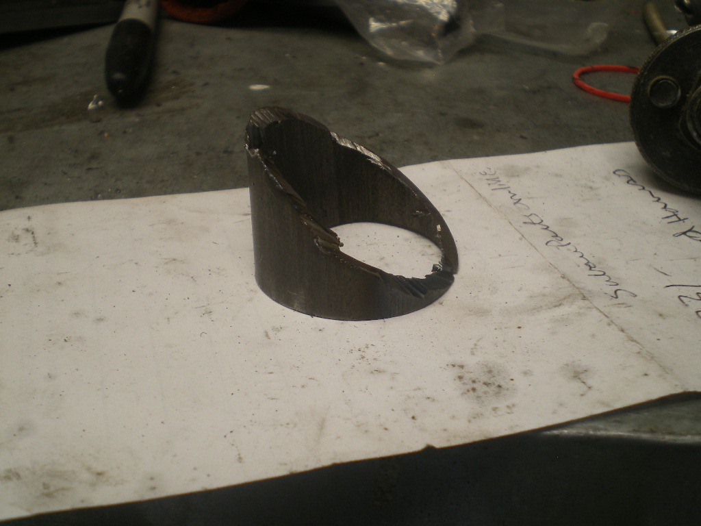
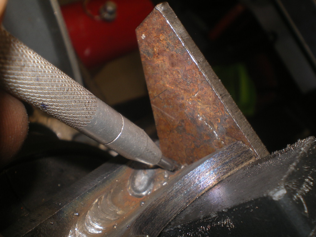
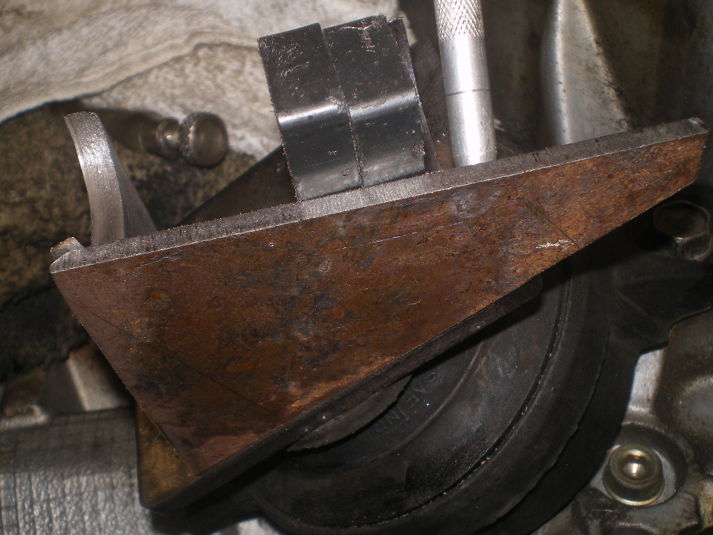
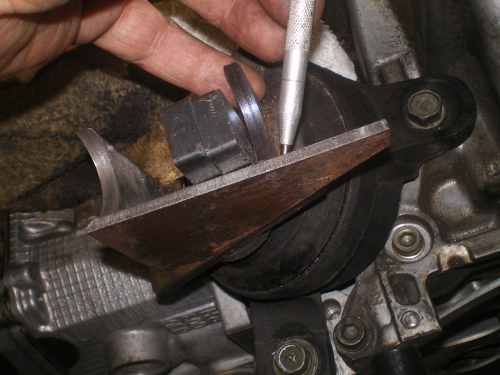
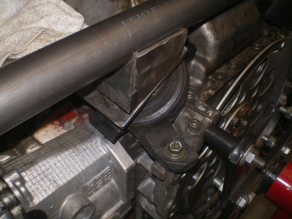
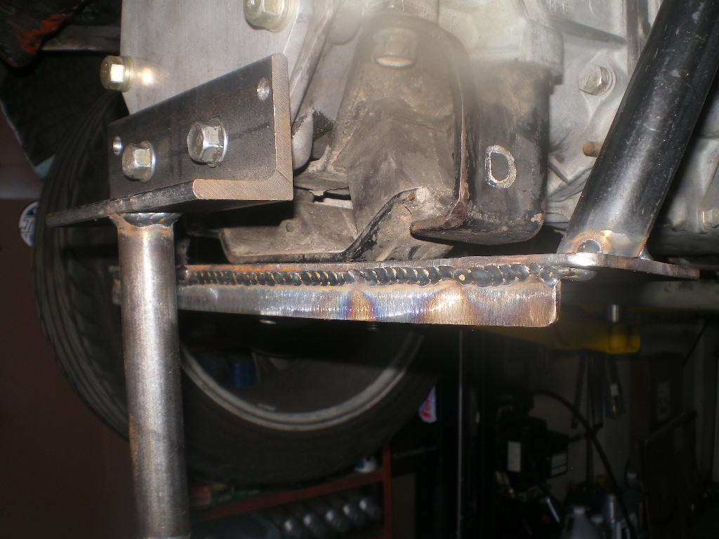
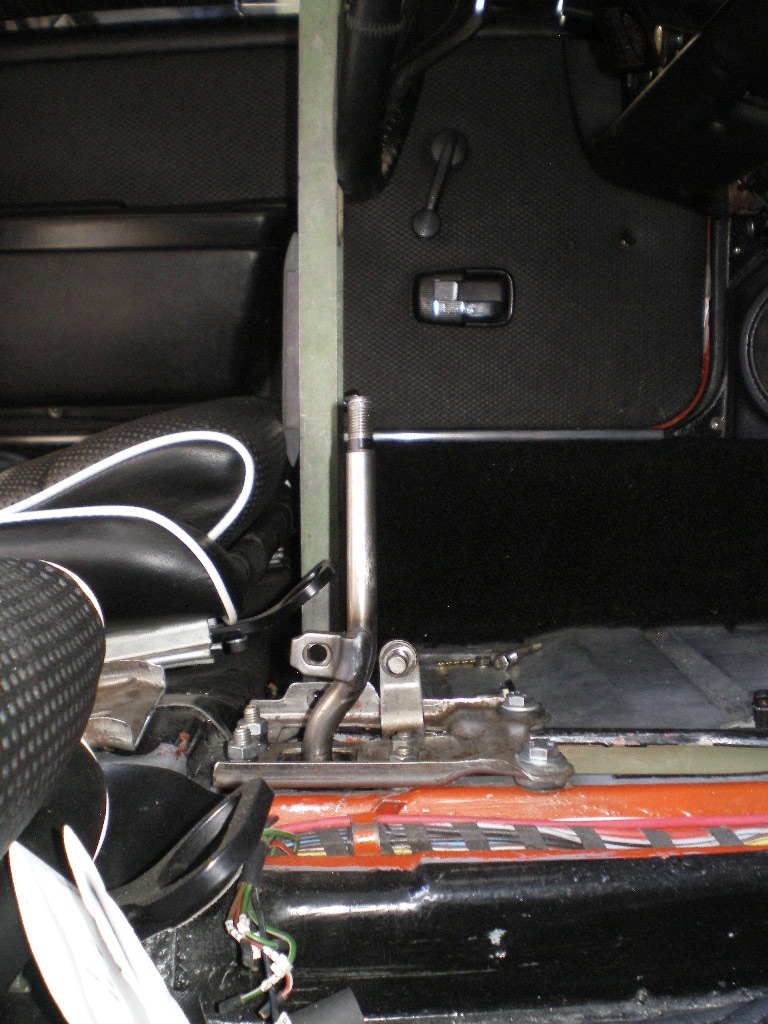
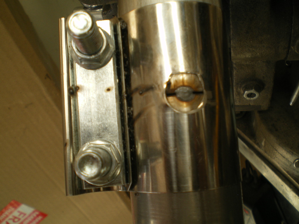
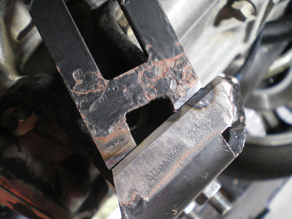
Now return the piece in place and hold the newly cut end very close to the front nut. This will give us room at the back of the plate for the transmission hanger later on. Allow just enough room for the washer to clear the weld bead. 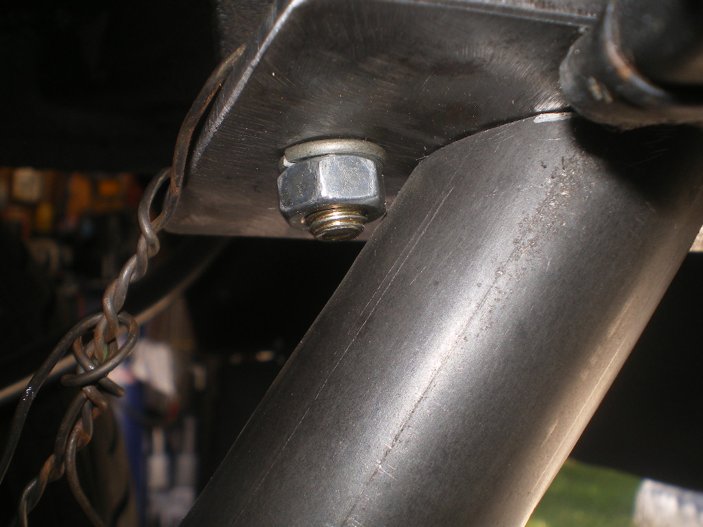
Now go to the front mount and carefully drop a marker thru the 1/2" hole making a mark on the tube. Try your best to be accurate but if not I've got a work around. Now your ready to take the piece to the drill press and drill it's first hole. The first hole will be 1/8". Why? Because odds are you've missed the mark a tiny bit and if so it is easy to correct. The rear attach plate is set at ~15 deg so we need to clamp the piece so that the cut end is at 15 deg. Once that is established we need to check to see if our drill bit is lined up with our mark. If it is then carefully drill the 1/8" hole. If that looks good then increase it to 1/4' or 6mm. Now return the piece to the car and using a long 6mm/1/4" bolt or threaded rod as I did, hang that end from the hanger and set it 1" below the angle iron. now check to see how your cut end mates up with the 3x5 plate. If the tube is for or aft of the desired location drill another small hole to place it in the correct location. Ideally the arc is still 90 deg to the floor but if it is slightly off 1-2 deg it won't matter. This is when you may need to remove a bit more off the cut end if the length is not parallel to the floor while maintaining that 1" gap. When complete with this task both tubes should be parallel to one another because we don't want the cross brace to be higher on one side than the other. 
It should end up looking something like this but not to worry. This end will be welded and no one will see an imperfect cut anyway.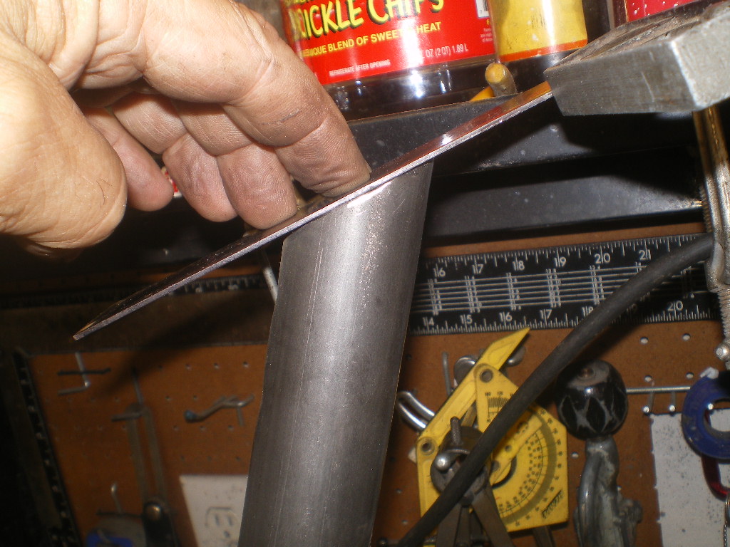
To be continued................
Posted by: 808 WRX Jul 6 2020, 01:39 PM
Once it's is secure be sure the section past or to the rear of the arc is perpendicular or 90 deg to the floor and that the long end is level or parallel to the floor. Ultimately the top of the tube should be 1" below the bottom of the angle iron bracket. This IS important. You may find you need to cut that angle piece twice in order to raise the back end enough to get it level while maintaining the 1" gap mentioned above and keeping the length level. Now is the time to mark the compound angle that will be trimmed off the top end. The 1st cradle I used a marks-a-lot but found the hacksaw blade to be much more accurate in transferring the mark because the blade could be held flush against both sides of the tape roll. Hold the roll flush against the plate. I needed to stretch the roll into an over same to work around the protruding bolts.
I am probably a month or two from building myself a cradle. So your timing is perfect and I am looking forward to this thread!
Quick question, why is the 1" gap important?
Posted by: Andyrew Jul 6 2020, 01:45 PM

![popcorn[1].gif](style_emoticons/default/popcorn[1].gif)

Awesome!!!
Posted by: tygaboy Jul 6 2020, 02:24 PM
Awesome!!!

Posted by: 914forme Jul 6 2020, 02:32 PM
Love the low tech cradle build.
The roll of tape and hack saw blade trick genius.
I would have used machinist dye, but that is me getting all fancy.
![whip[1].gif](style_emoticons/default/whip[1].gif) back to the day job for me
back to the day job for me
Posted by: JRust Jul 6 2020, 08:40 PM
Looks great Kent! Love to see the step by step there
Posted by: 2mAn Jul 6 2020, 09:02 PM
Love it. I could hear the garage cursing because I’m usually yelling at that same a$$hole lol
Posted by: 76-914 Jul 6 2020, 09:51 PM
Once it's is secure be sure the section past or to the rear of the arc is perpendicular or 90 deg to the floor and that the long end is level or parallel to the floor. Ultimately the top of the tube should be 1" below the bottom of the angle iron bracket. This IS important. You may find you need to cut that angle piece twice in order to raise the back end enough to get it level while maintaining the 1" gap mentioned above and keeping the length level. Now is the time to mark the compound angle that will be trimmed off the top end. The 1st cradle I used a marks-a-lot but found the hacksaw blade to be much more accurate in transferring the mark because the blade could be held flush against both sides of the tape roll. Hold the roll flush against the plate. I needed to stretch the roll into an over same to work around the protruding bolts.
I am probably a month or two from building myself a cradle. So your timing is perfect and I am looking forward to this thread!
Quick question, why is the 1" gap important?
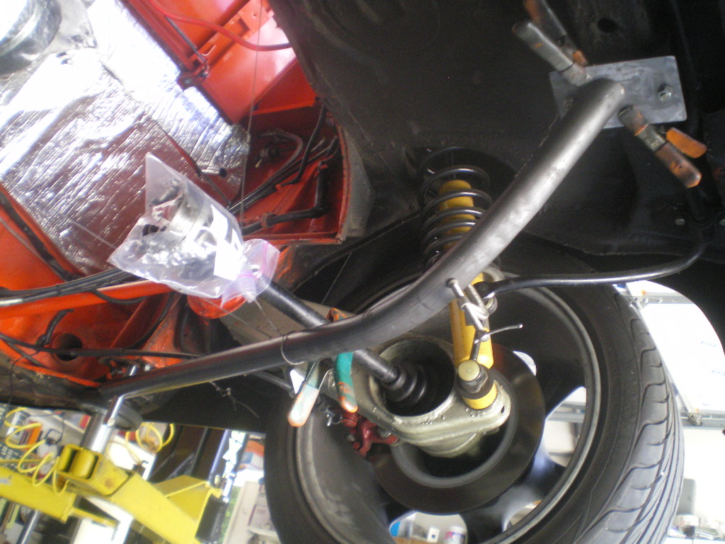
Two reasons. I didn't flip the throttle body and this leaves enough room between the top of the throttle body and the trunk bulkhead so that the steel fuel lines can pass over unimpeded. Look at my build thread on the black '73 and you'll see better than I can explain. It's in the Member Build Threads section, very top. Perhaps more importantly is ground clearance. I measured 5 1/2" from the ground to the windage flaps attached at the bottom of the firewall. I don't use those flaps but I thought clearance that was a good height to place the bottom of the engine. It was the lowest point on the car and I didn't want to exceed that.
Posted by: 76-914 Jul 6 2020, 10:04 PM
Awesome!!!
Awesome!!!
Love the low tech cradle build.
The roll of tape and hack saw blade trick genius.
I would have used machinist dye, but that is me getting all fancy.
back to the day job for meLooks great Kent! Love to see the step by step there
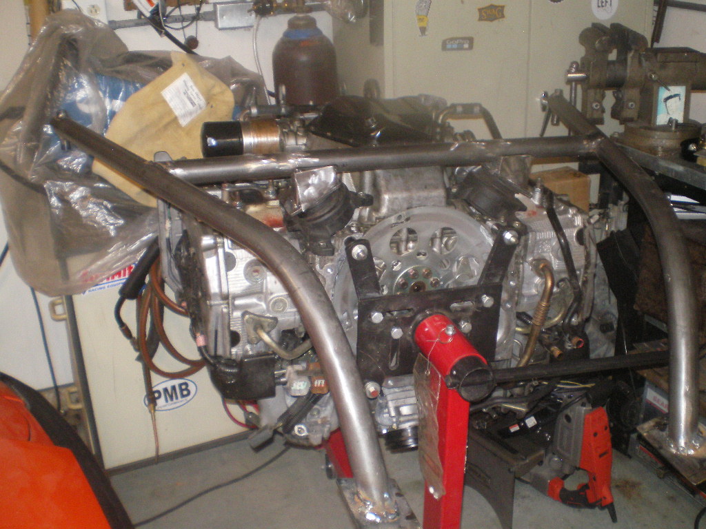
Just wanted to say thanks. Coming from you guys is the best. Stephen, I miss you presence. I've learned of the dye and center punches from you. Game changers! I looked over my last build and was horrified to see I didn't respond to many comments. How rude of me. I get tunnel vision during builds and overlook things like this. I promised myself that I'd respond to all this time. No matter how busy I may believe I am. I'll be awhile before continuing the cradle as I'm awaiting some bushing stock which I used to buy locally. Should be here next week. So today I got the engine upon the stand so I can start putting some of those cut and drilled pieces together that form the motor mounts. To be continued.........
Posted by: andys Jul 7 2020, 11:24 AM
This is what I did for my cradle in case it helps. Different trans, different motor, but it's a cradle nevertheless. I paid a hotrod shop to make the bends.
Andys
Attached thumbnail(s)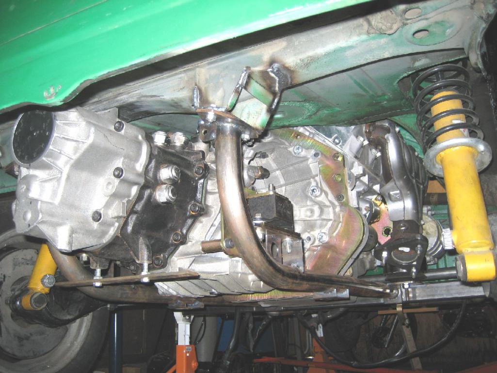
Posted by: 76-914 Jul 7 2020, 12:59 PM
This is what I did for my cradle in case it helps. Different trans, different motor, but it's a cradle nevertheless. I paid a hotrod shop to make the bends.
Andys
That is very nice. This is my 2nd one and I’m just documenting in case some one wants to build their own and save $600-$800. What’s different about mine is it has detachable casters that allows me to roll the drive train in and out. Thank and it is very light.
Posted by: 76-914 Jul 7 2020, 09:38 PM
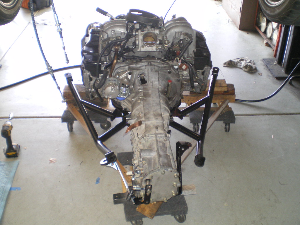
Round 4; I was able to steal away for 2 hours this afternoon so I began assembly of the hard mounts themselves. Remember these pieces? It's time to use some of them. 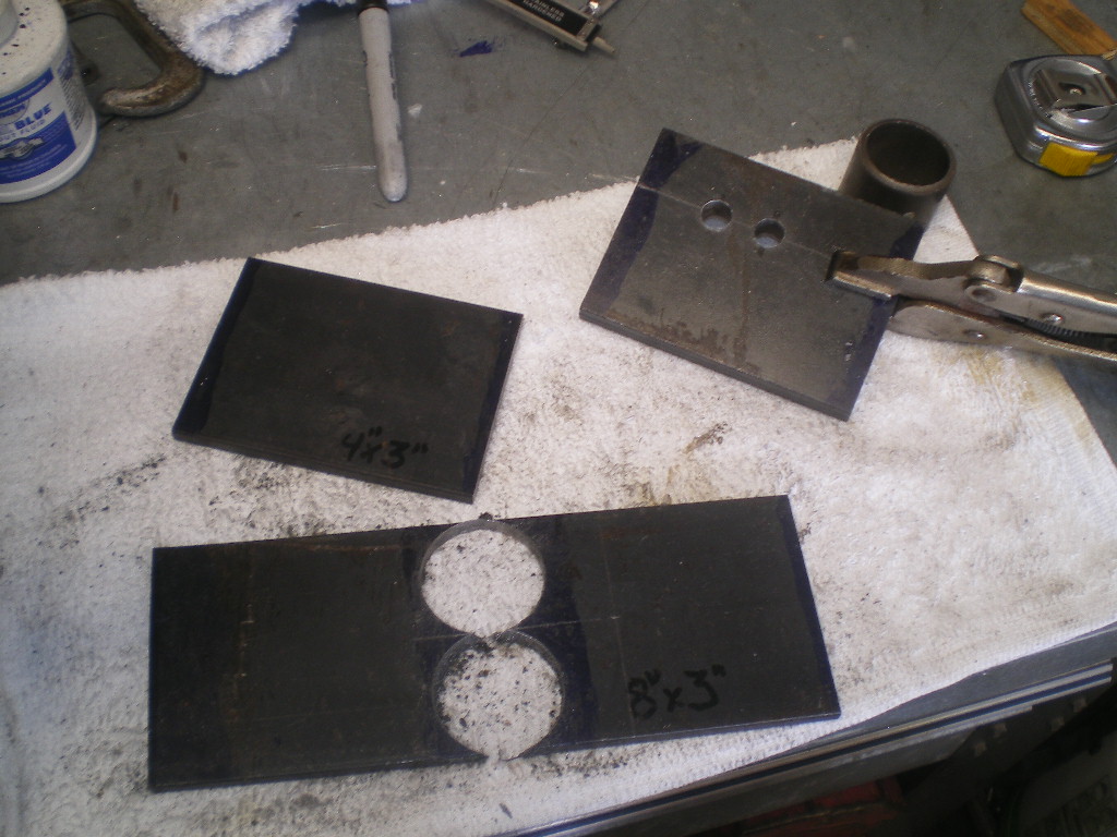
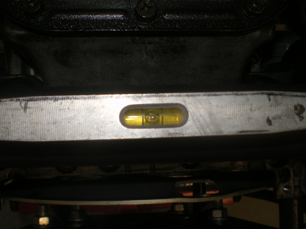
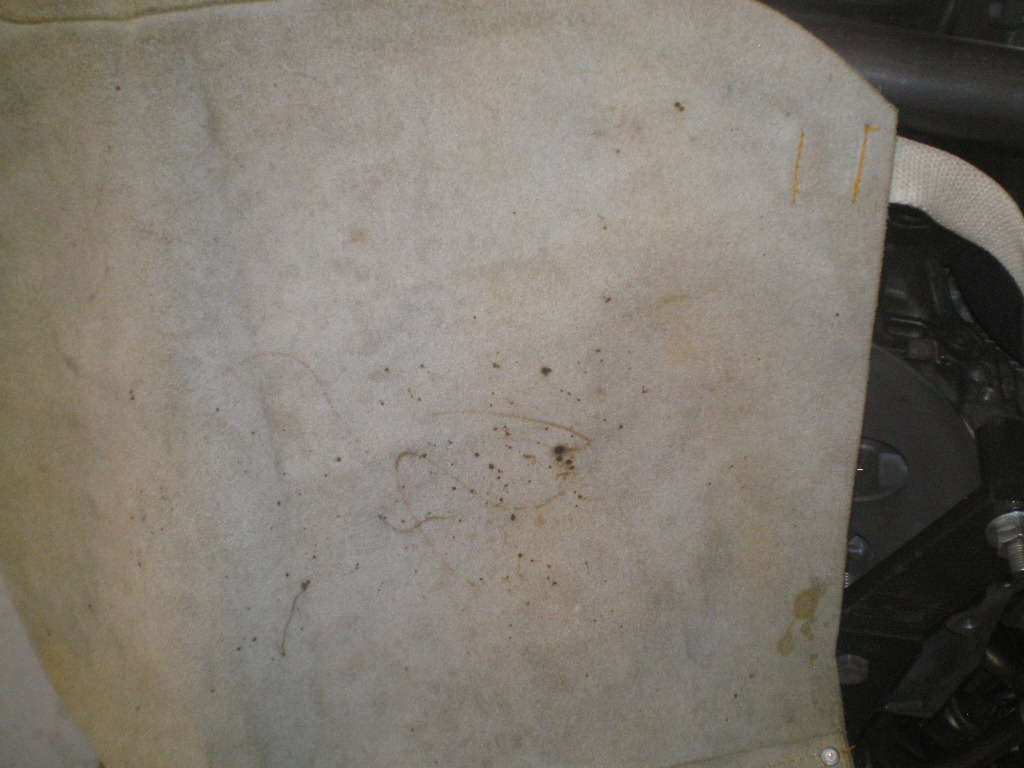
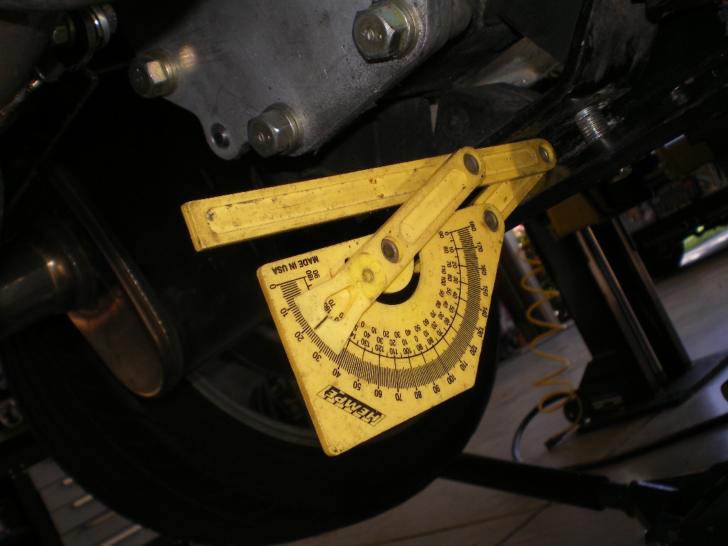
First I rotate the engine so it's bottom side up with the factory rubber mounts installed. Then level it. If you've a cheap HF engine stand like mine you'll do well to check for level often. I placed the angle finder on the oil pan and also the engine case to confirm the oil pan was not out of whack. The afternoon sun was glaring in case you're wondering about the popcorn box. 
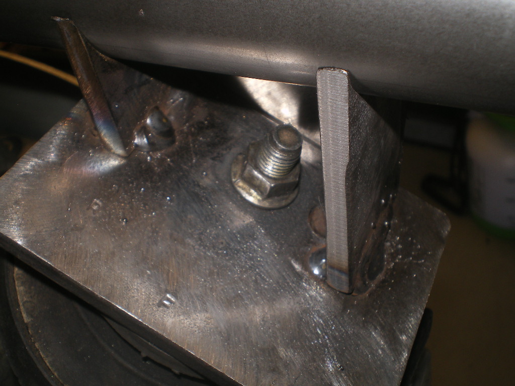
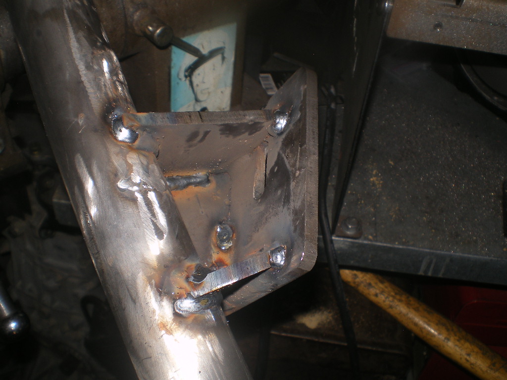
Next attach the 4x3 plates that were drilled to match the rubber mounts. Now take one side of the plate that was drilled with 2-1.5" holes and split it between the holes. Now you have 2 pieces that have 2 "U's" if you will. Take one of those measure down 3/4" from the lowest point of the "U" and cut it down to size. After this you can split this piece down the middle. You now have 2-1.5" wide "U' tabs that are appx 1.5" tall @ the highest point and 3/4" tall if you measure to the bottom of the "U". These are the short inner pieces that will support the cross bar. There will be 2 longer pieces and they will tie into the shorter pieces w/ some 3/16" but I'm getting ahead of myself. Looking at the 1st pic below you will see I used some magnets to support these short "U" shaped tabs. I located the tabs so they line up with one edge of the rubber mount so the support is above the mount and not past it. I didn't want the load outside the area of the mount. I used a finish nail to hold the tab vertical. The tab is placed 3/16" away from the edge of the 4x3 plate to allow for the piece of 3/16" I mentioned above.
I repeated this step on the other side but when I place the crossbar in the tabs the left side was slightly higher than the right one. This can be expected unless your making these tabs on a mill.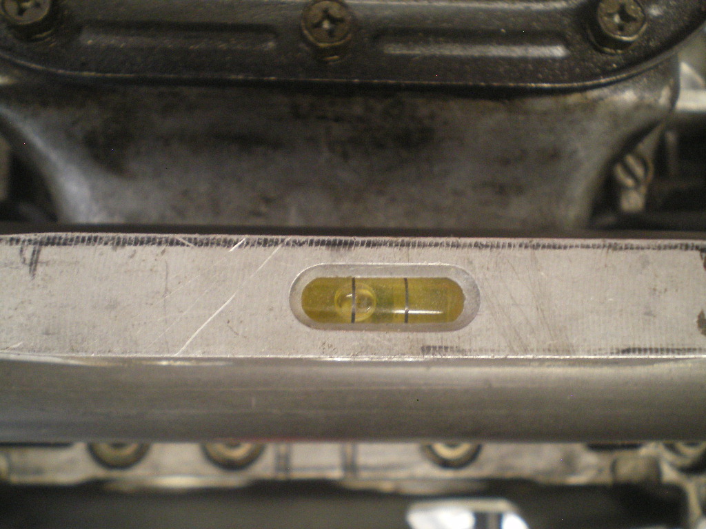
But the fix is simple. I ground this tab with a slight angle and lowered the nail a hair which brought the bar back to level.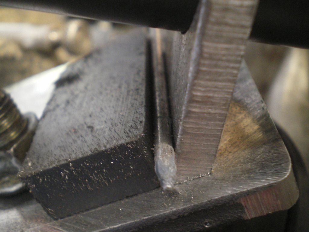
Next check for level at the engine and crossbar then a couple of spot welds and check for level again. 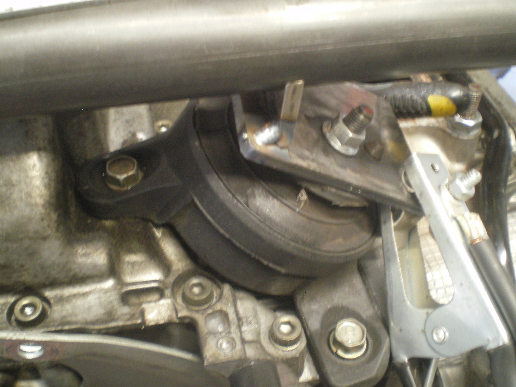
to be continued.................
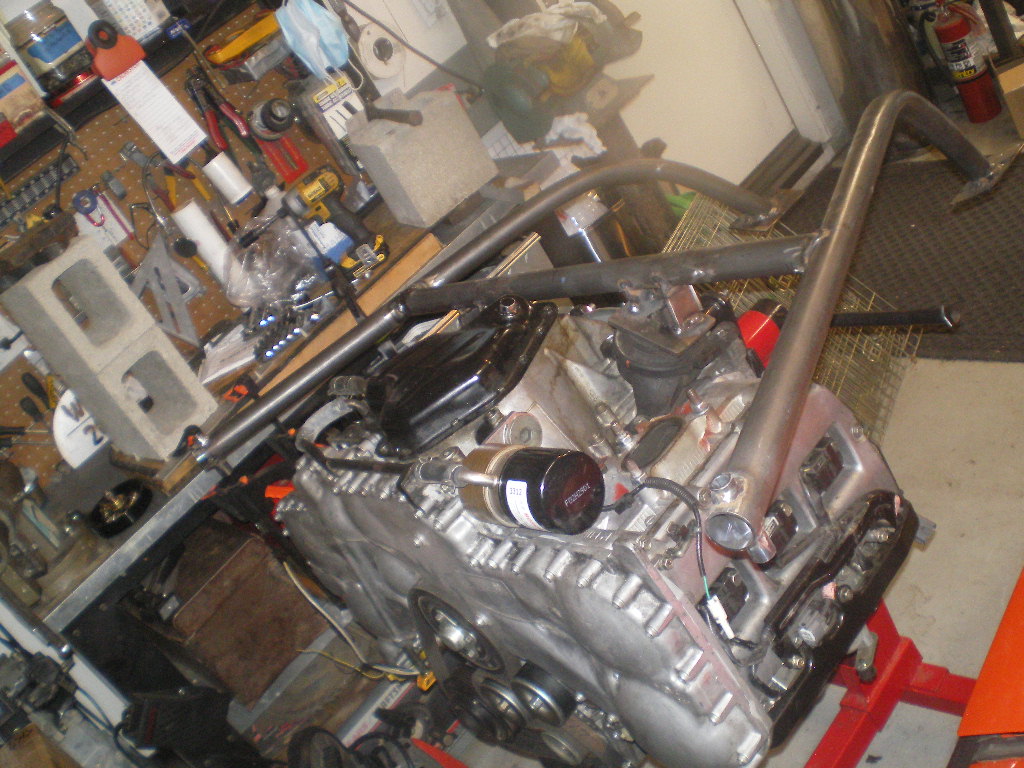
Posted by: 76-914 Jul 8 2020, 03:29 PM
OK, things are fixing to get wordy so bare with me. In this next part we are going to cut the longer U tabs to length, tack them in place then cut the piece that will eventually tie the U tabs together. I'm going to throw a lot of pics at you in hopes it will answer any unanswered questions. If your long U tabs don't end up exactly like mine, so be it. What is important here is that all four U tabs contact the crossbar and the crossbar remains level, i.e. square to the engine. Other than that it's just aesthetics. In this 1st pic the piece isn't split vertically yet because we're determining where to cut it. And both pieces should be the same length. Again I use magnets to hold the pieces. If you don't see it, it is on the other side. 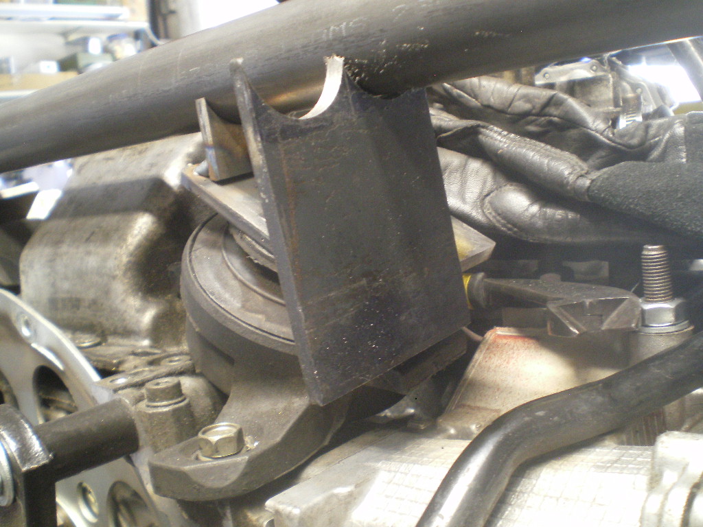
[attachmentid=752025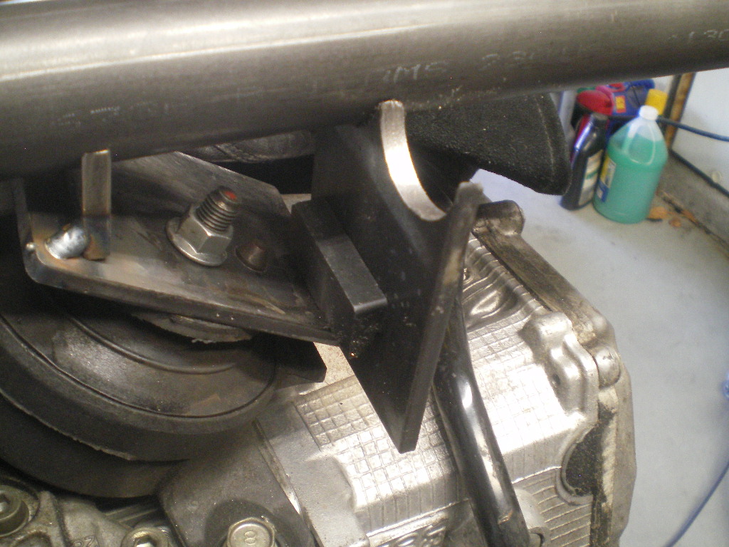
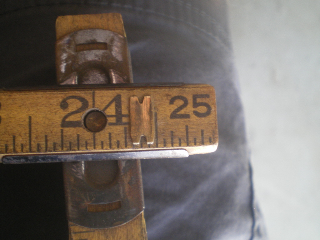
This is how I determined the height. The flat of this caliper happened to be the correct width so this is what I used to determine the cut line or height of the U tab. I held it level and at the spot I want the inner edge of the U tab to be then marked the tab and the caliper. LOL. It's a cheap tool anyway. 
Then I cut it on the mark and split the piece giving me 2 equal length U tabs. The same process was used for the shorter U tabs.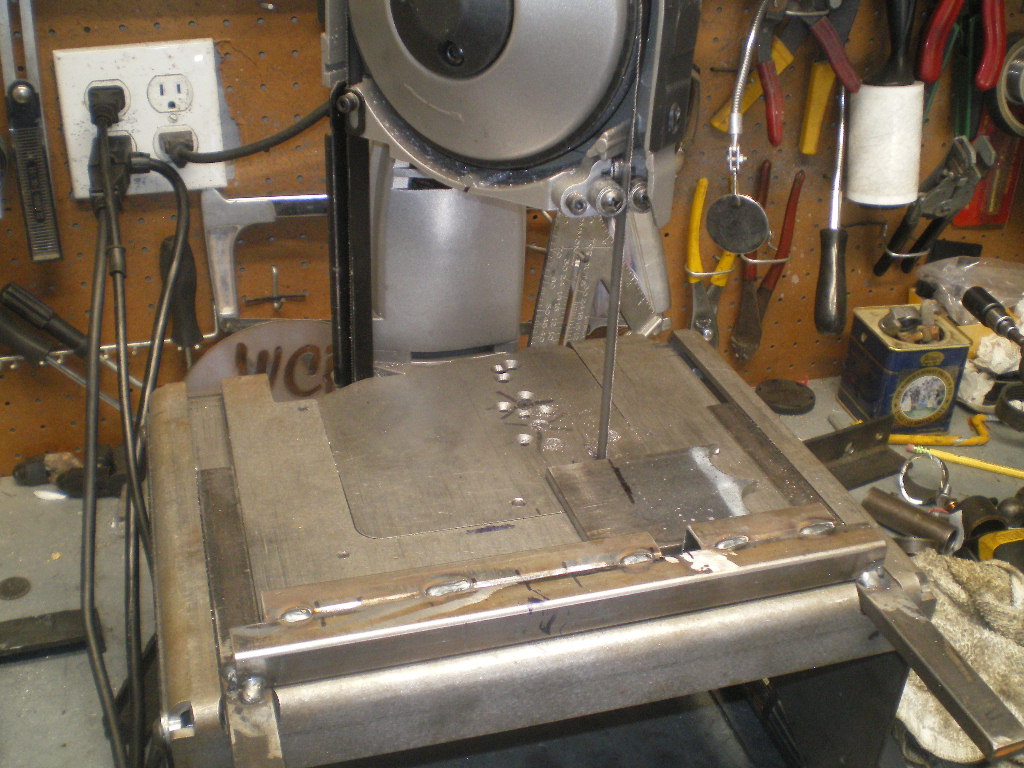
Now with the crossbar sitting in the 2 tacked U tabs position the longer tabs so they contact the bar and plate. Don't get it too close to the nut that you will need to wrench on later. Other than that it won't matter the exact location. Or whether it is square with the other tabs.
Once these are positioned go ahead and tack them in place. We're not tacking the crossbar in place yet. That's the next to last step. 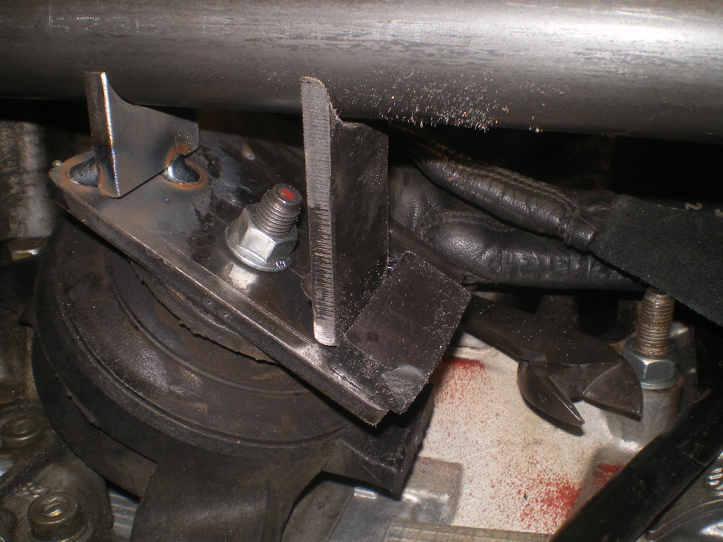
Remove the bar and mounts from the engine and complete welding the tabs to the plate. Avoid getting any buildup in that 3/16" area or you'll need to bring it down.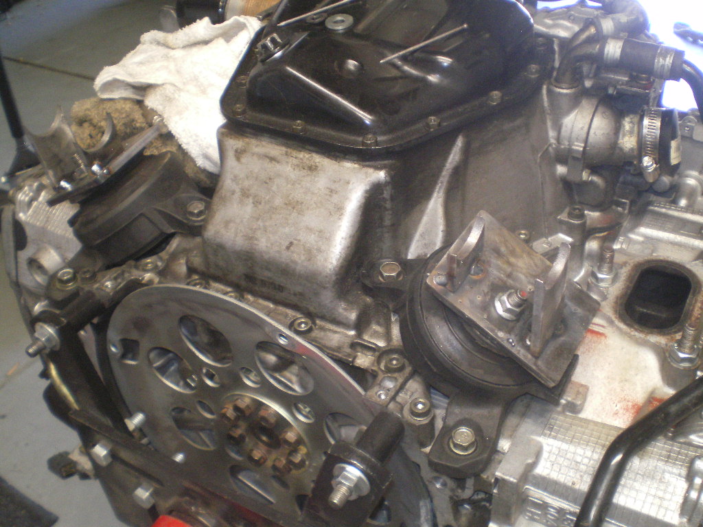
I forgot to mention to check that the crossbar still contacts all 4 tabs and is level before completing the welds on the tabs. 
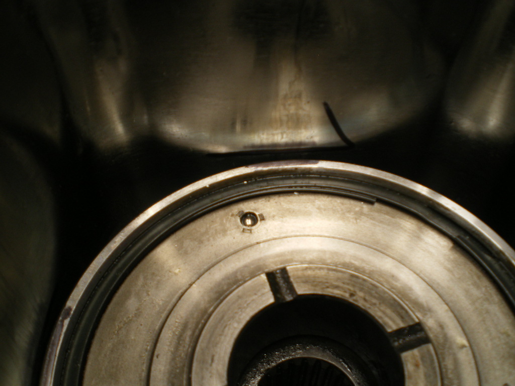
And while I'm at it I should mention that these dimples on the backside of the plates are to allow a flush fit with the mount since there are these protruding rivet heads.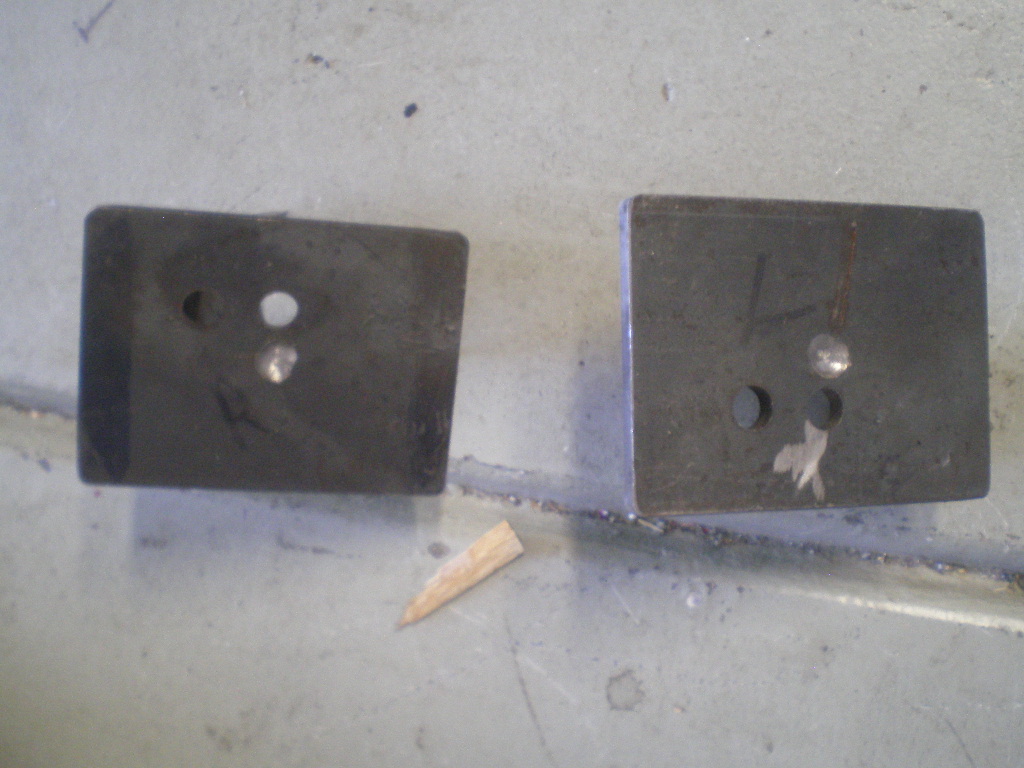
Attached image(s)
Posted by: 76-914 Jul 8 2020, 03:37 PM
The Poltergeist is back. That last pic isn't supposed to be there. I noticed it listed as an attachment in the edit file yet it didn't show on the version you see. So I added it where it belongs and lo and behold it shows up at the end of the post too.
Posted by: 76-914 Jul 8 2020, 03:58 PM
Now for the 3/16" reinforcing pieces. This rusty scrap looks like most of my steel before sanding the rust off but I leave it for now as it makes it easy to see the scribed marks. If it is new metal I use the dye. Just hold it in place and scribe the outline. After a couple of cuts and sanding it is complete. These won't be tacked in place for awhile as to give access to welding the bar to the tabs later.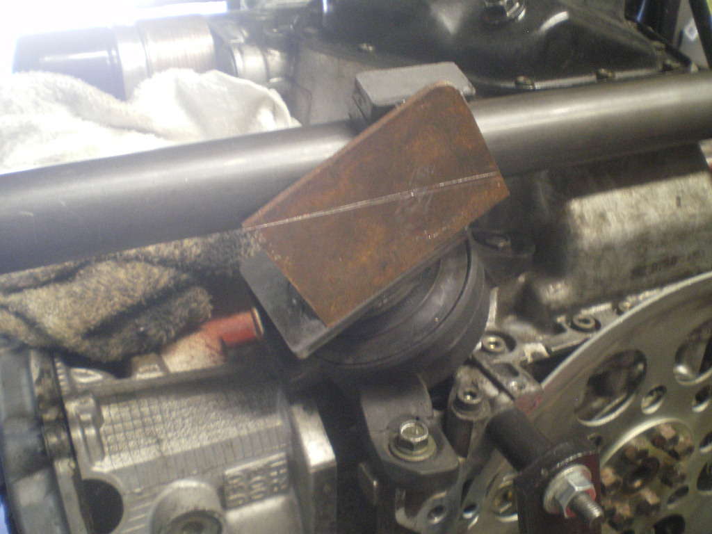
Posted by: 76-914 Jul 8 2020, 04:06 PM
And this is why I wear an apron when welding. After having some slag land in my belly button a few years back I quit tempting fate. 
to be continued....................
Posted by: euro911 Jul 8 2020, 04:32 PM
Looking good, Kent. (subscribed)
Posted by: Andyrew Jul 9 2020, 08:45 AM
That looks STOUT! Might be going a bit overboard on the braces there Kent 
Also remember disassembly when building. You have that bolt at an angle so you'll have to be able to pull it out at an angle when removing. Just FYI that could be difficult to coordinate.
Posted by: 76-914 Jul 9 2020, 08:04 PM
Looking good, Kent. (subscribed)
That looks STOUT! Might be going a bit overboard on the braces there Kent
Also remember disassembly when building. You have that bolt at an angle so you'll have to be able to pull it out at an angle when removing. Just FYI that could be difficult to coordinate.
@http://www.914world.com/bbs2/index.php?showuser=172 Well I had the 1/4" on hand and I'm trying to limit my trips out. That CV19 thing. The first one I made from 3/16" and I've punished that set up w/o any problems. I did elongate the holes in the first one if you look at that build thread. I'm on the fence as to whether I should repeat that step or just loosen the rubber mount from the engine instead. I'll decide before I weld the bar in place so I can chunk them in the mill to elongate.
http://www.914world.com/bbs2/uploads/post-9964-1374796230.jpg
Posted by: rhodyguy Jul 11 2020, 07:03 PM
That's a very handsome table you have for your band saw.
Posted by: euro911 Jul 11 2020, 10:02 PM
I did, however, purchase a HF welding cart and some supplies, but misplaced my helmet somewhere along the line
Posted by: 76-914 Jul 12 2020, 12:47 PM
That's a very handsome table you have for your band saw.
I did, however, purchase a HF welding cart and some supplies, but misplaced my helmet somewhere along the line
Well don't let it intimidate you. Welding is a lot like fiberglassing. You can always grind it off and do it again.
Posted by: 76-914 Jul 22 2020, 05:27 PM
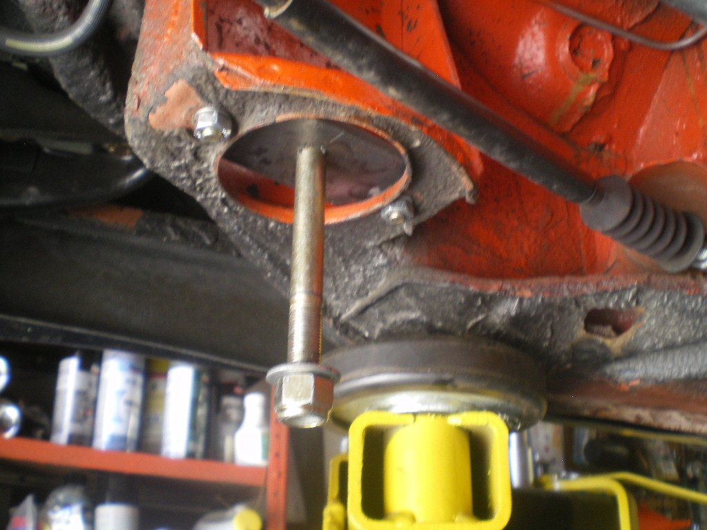
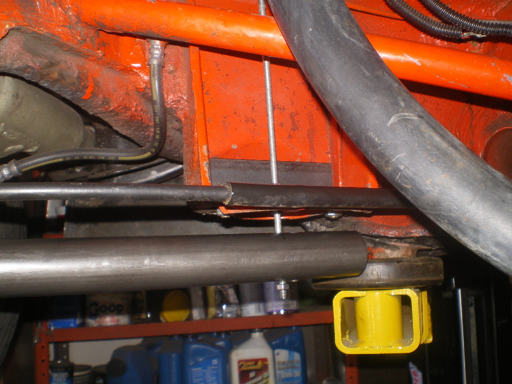
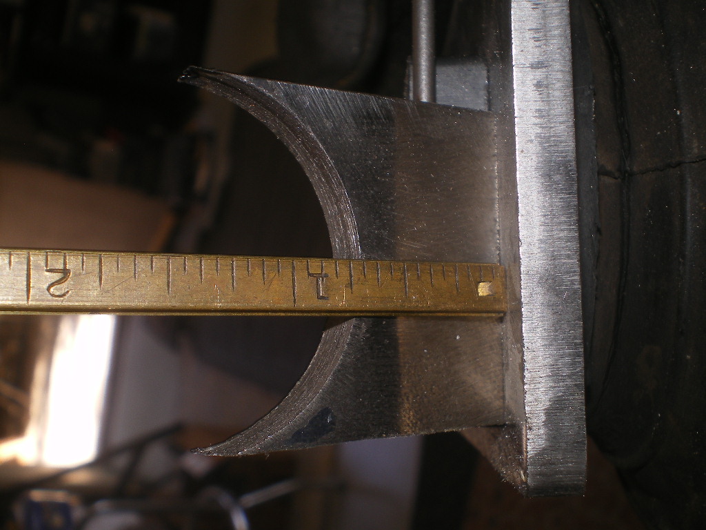
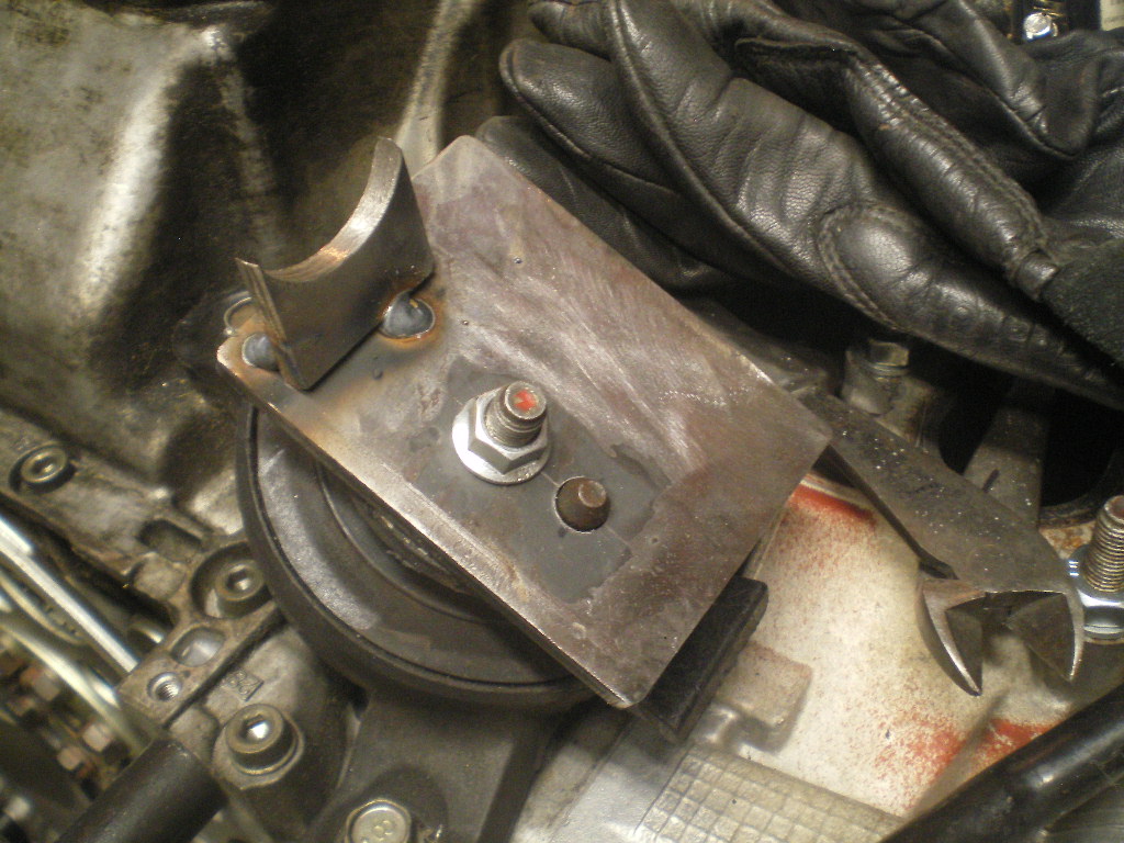
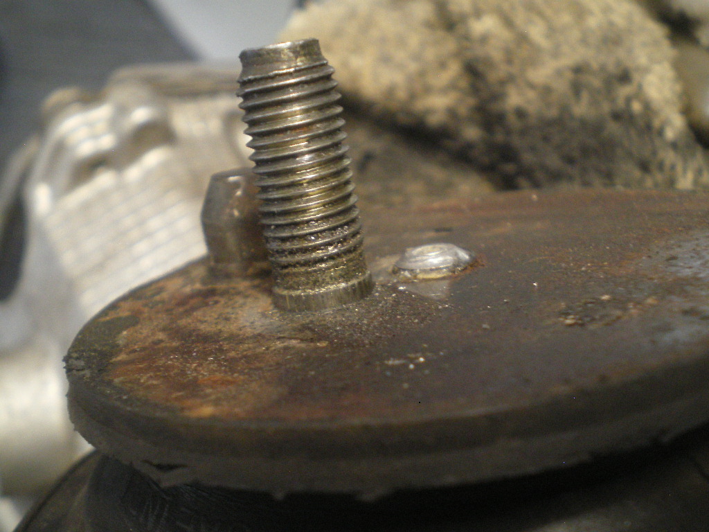
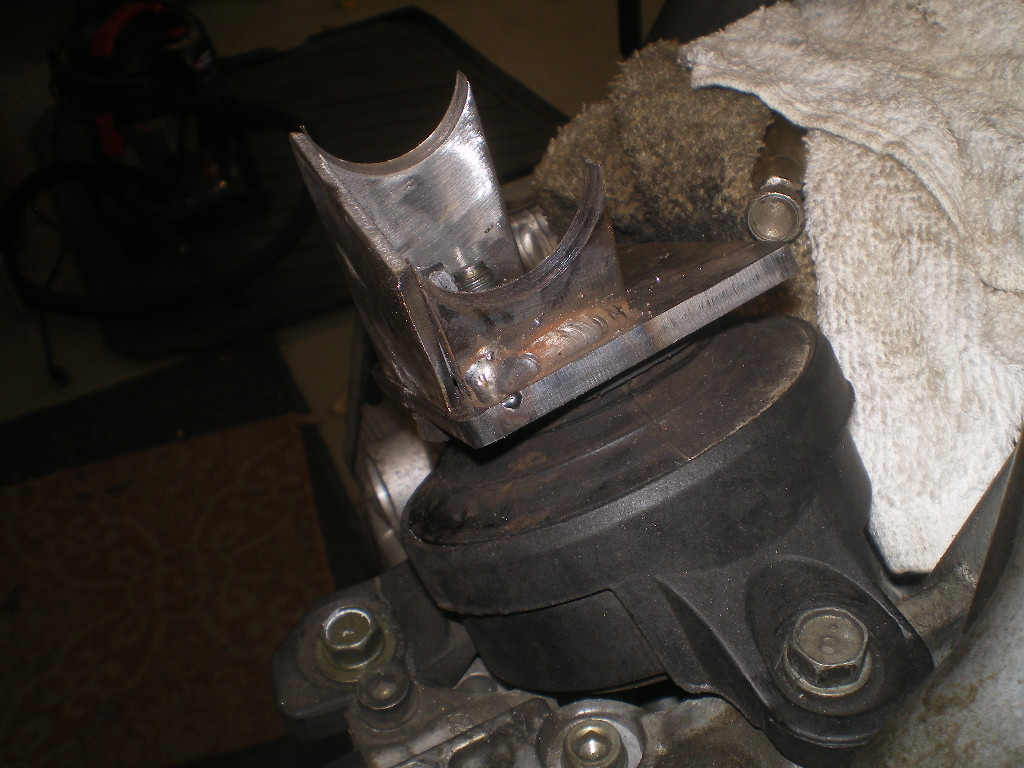
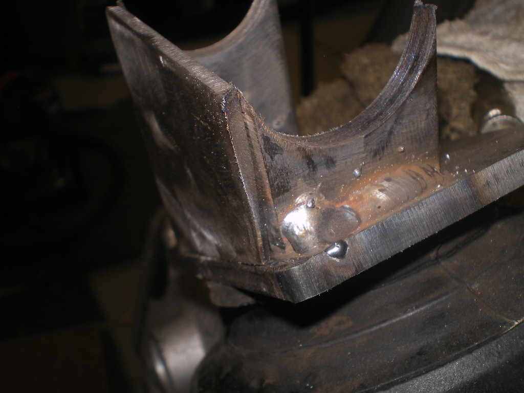
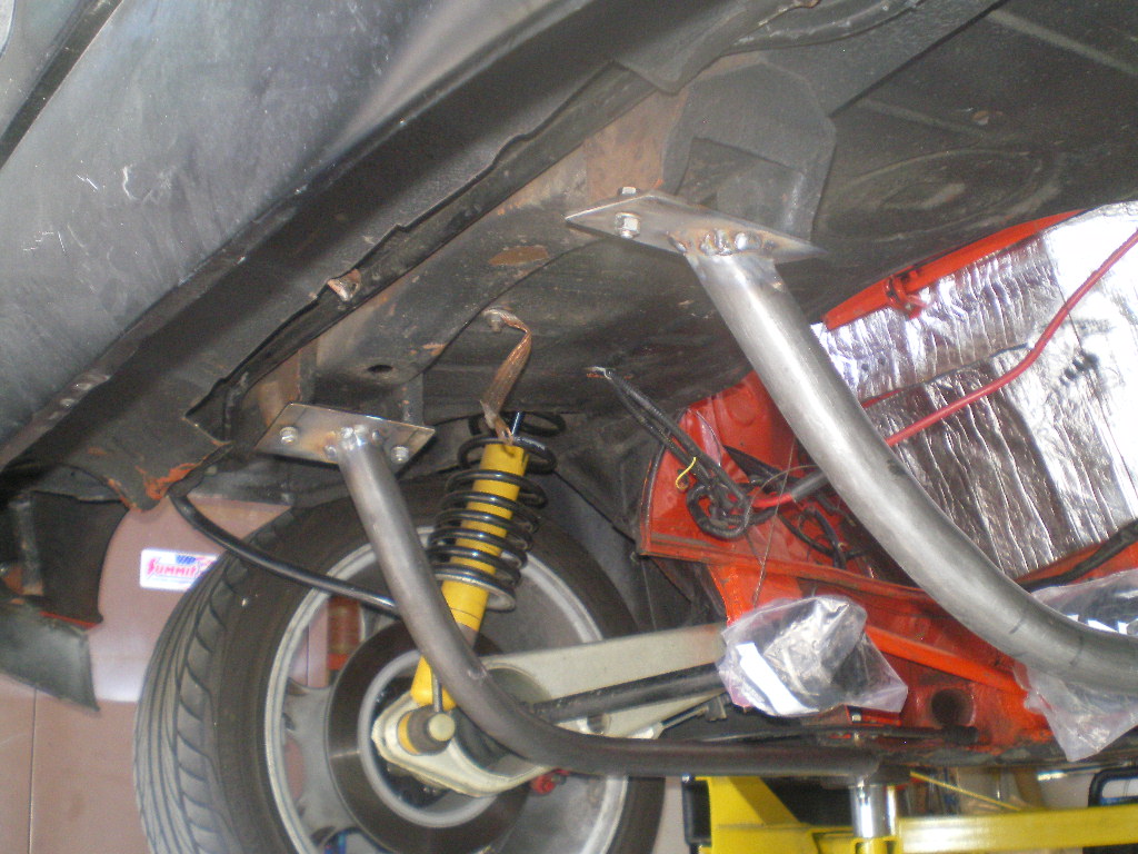
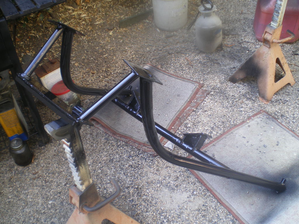
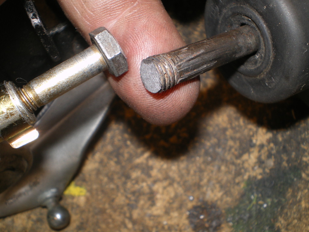
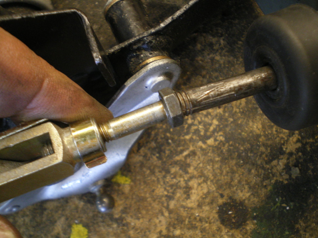
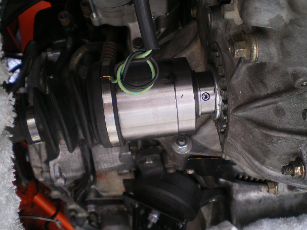
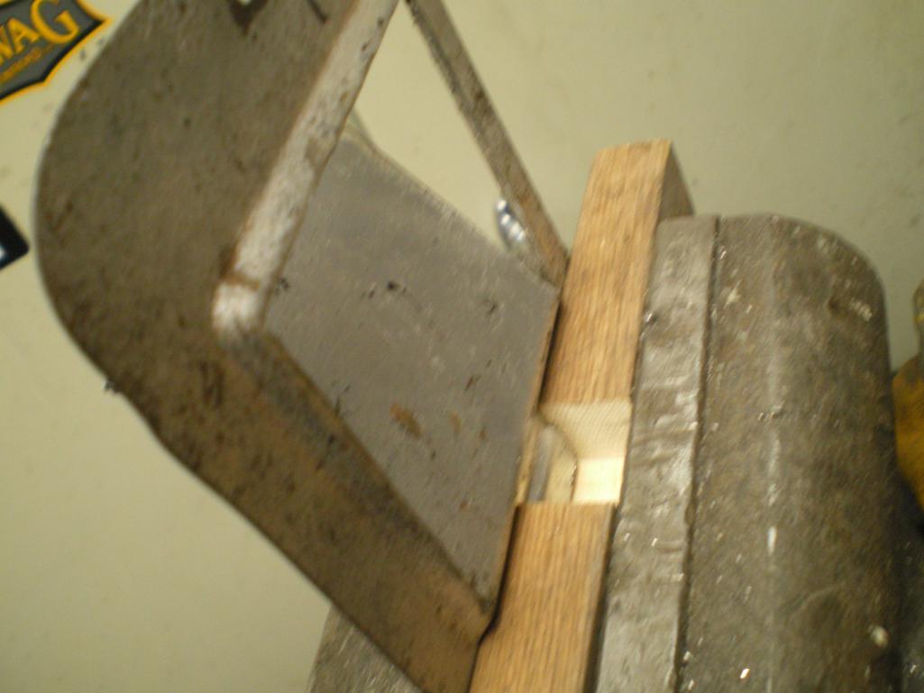
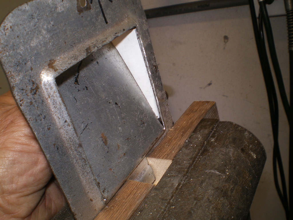
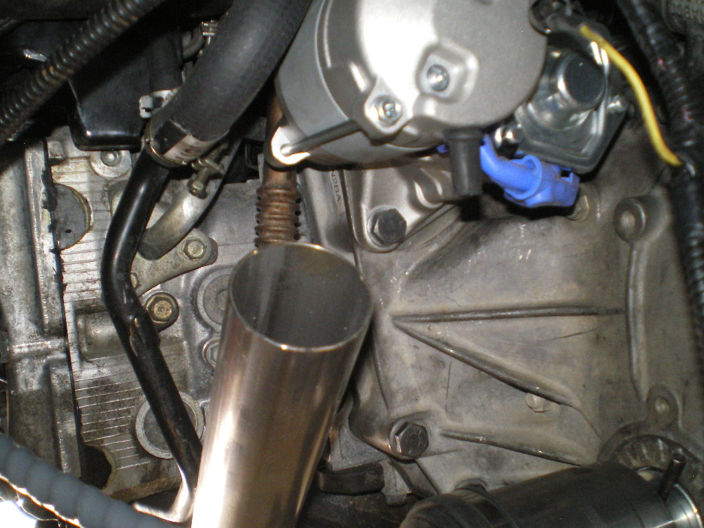
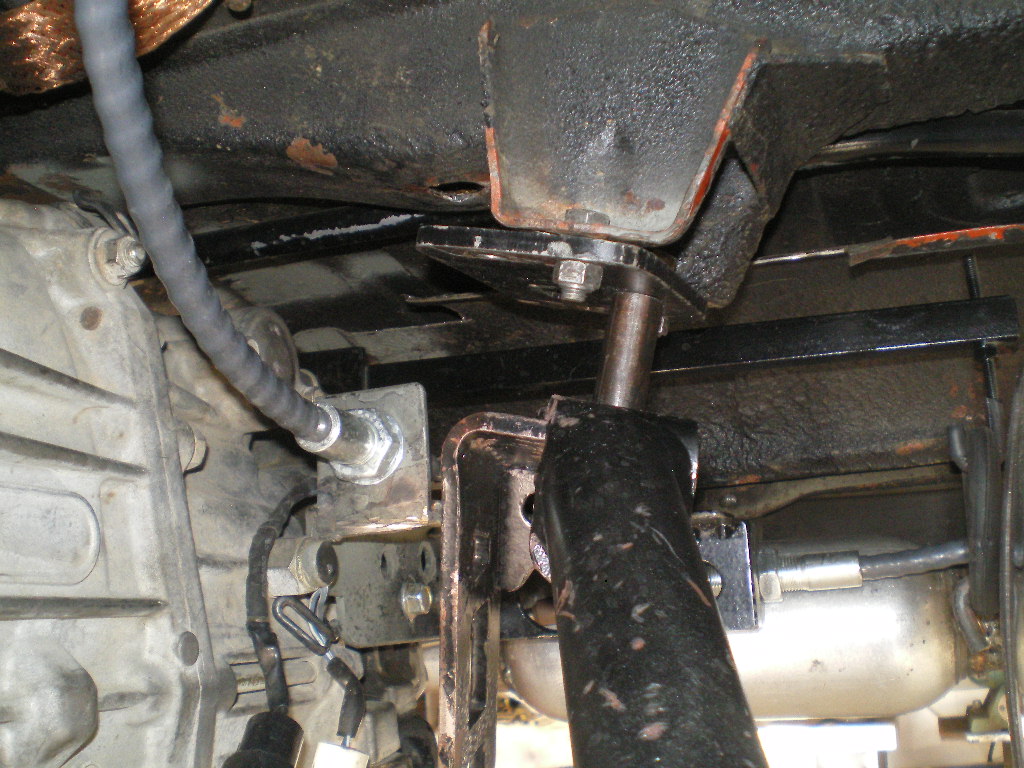
The steel spacers or bushing stock arrived last week so I was able to complete the engine cradle sans the transmission hanger part. Now that you know where the center of the front hangers are the next step is to drill those 1/4" out to 3/4". Since the arbor bit has a 1/4" pilot bit we will use that hole to align the 3/4" hole saw before drilling. To make sure I'm not "catty wamposed" I position the tube so that the 1/4" bit, still in the drill press, so that it bit passes freely thru both sides before clamping the tube in place. Next I remove the 1/4" bit and chuck the 3/4" arbor bit in place. Now it's just a matter of running the 3/4" bit thru. If you're "on the money" the steel spacer will need a bit of persuasion to pass thru the tube. If it doesn't, no big deal. It just makes it easier during the next few steps as it will not need to be hung or supported on this end. 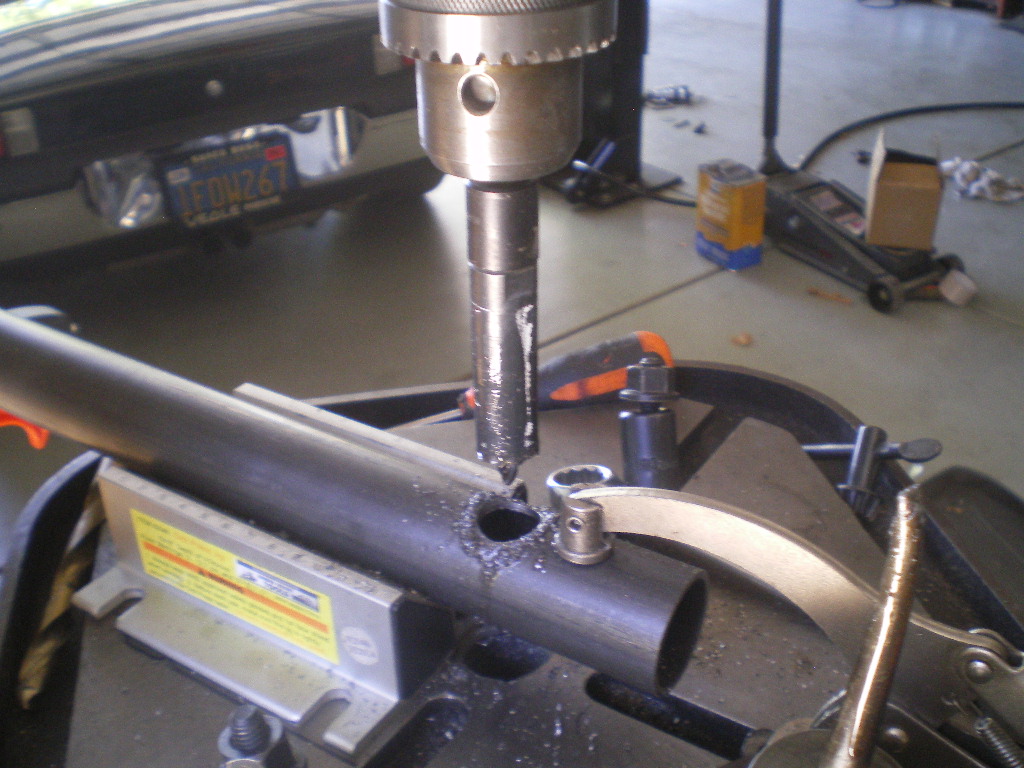
Here is the right side in place. The steel spacer is still 4" long at this point and will be cut down to 3" before welded in place. I know the picture shows to cut it 3 1/2" but that is incorrect. 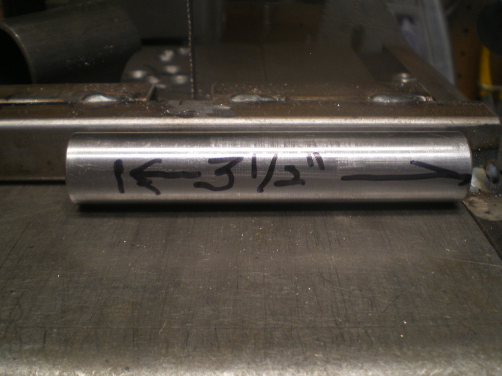
Now check the tube for level and adjust the tube up or down the steel spacer until it is level. Now check to see that the other end is in the correct spot on the 3"x4" plate. Once you're satisfied tack both ends and recheck for level and position. If it didn't slip or move go ahead and weld both ends as much as you can. You can finish any areas you miss once we remove the cradle from the car. Why do it this way? Shrinkage! I learned that lesson on my 1st cradle. By doing it this way we are using the car as a jig to prevent any shrinkage. It's a PITA welding overhead and in tight areas and your welds will look like  but in the end you'll be glad you did. I think I'll make a jig for future cradles so I don't have to do this in the future. Oops doubled up on that last pic.
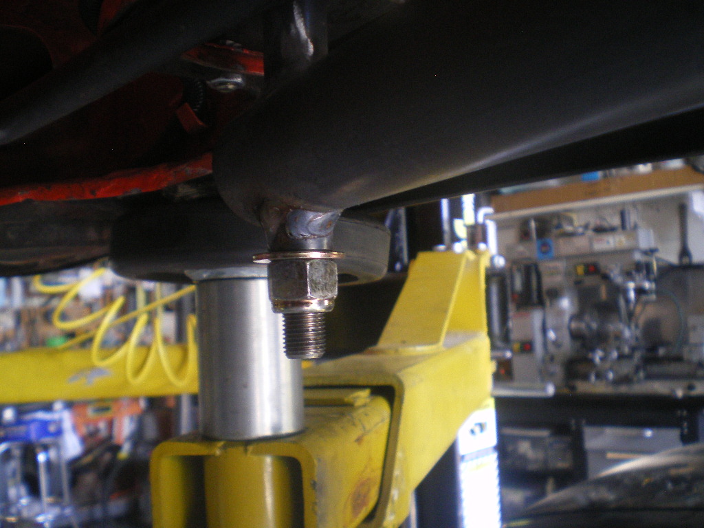
Attached image(s)
Posted by: euro911 Jul 22 2020, 06:01 PM
You make it look like you know what you're doing there ... 
Posted by: 76-914 Jul 22 2020, 06:32 PM
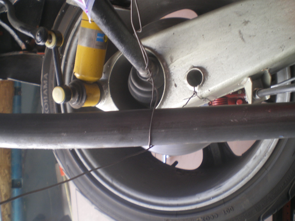
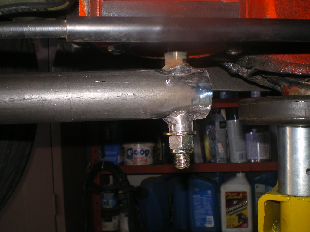
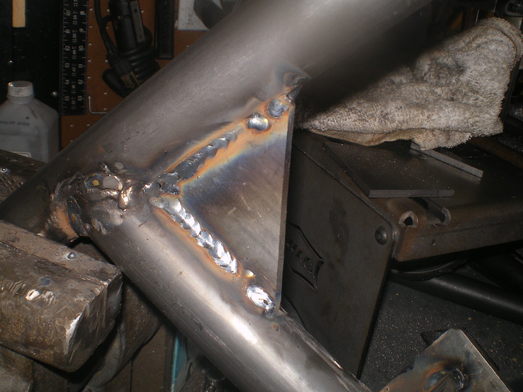
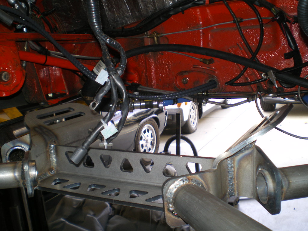
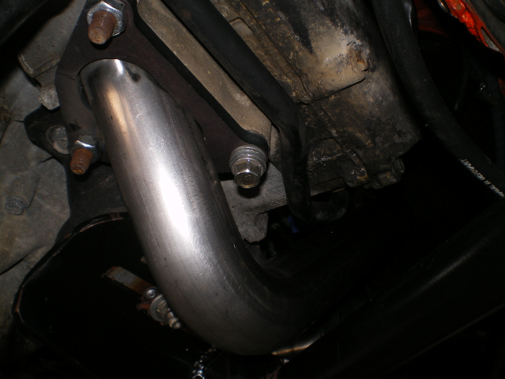
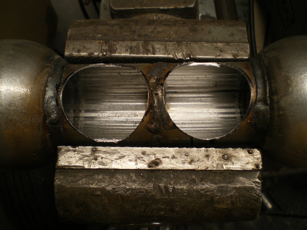
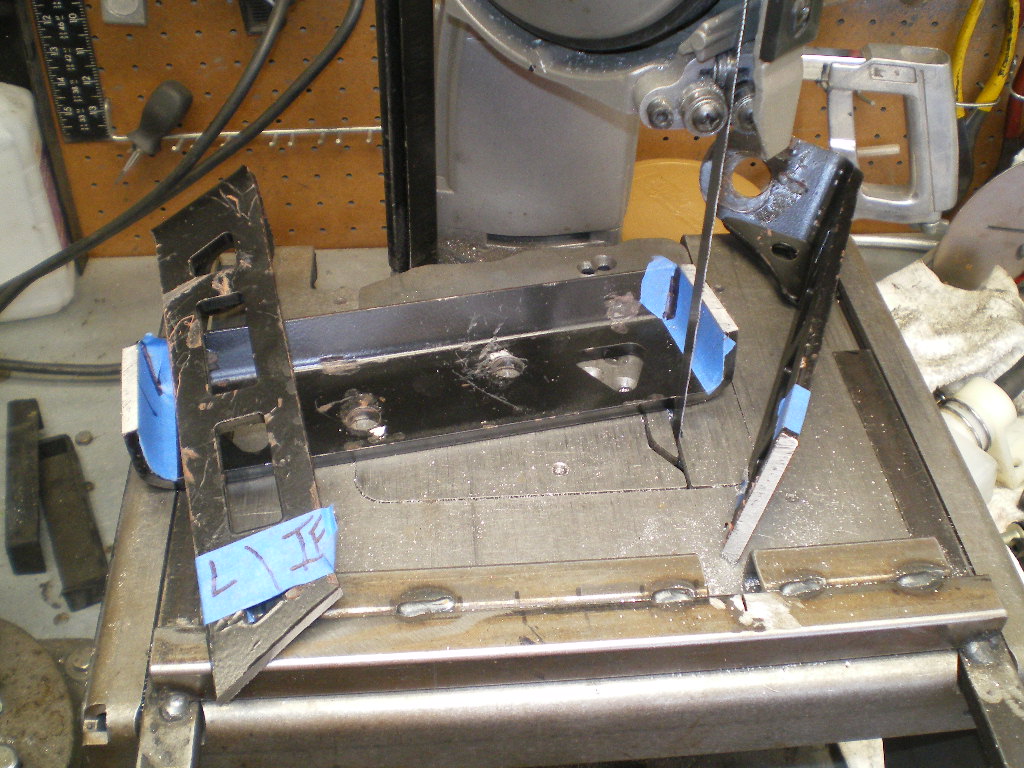
Now it's time to take this cross member tube and cut it to length.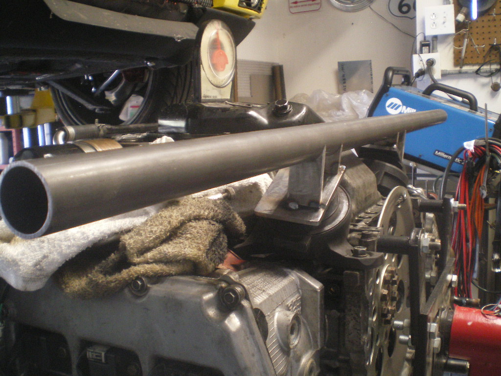
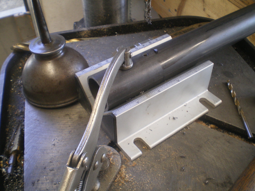
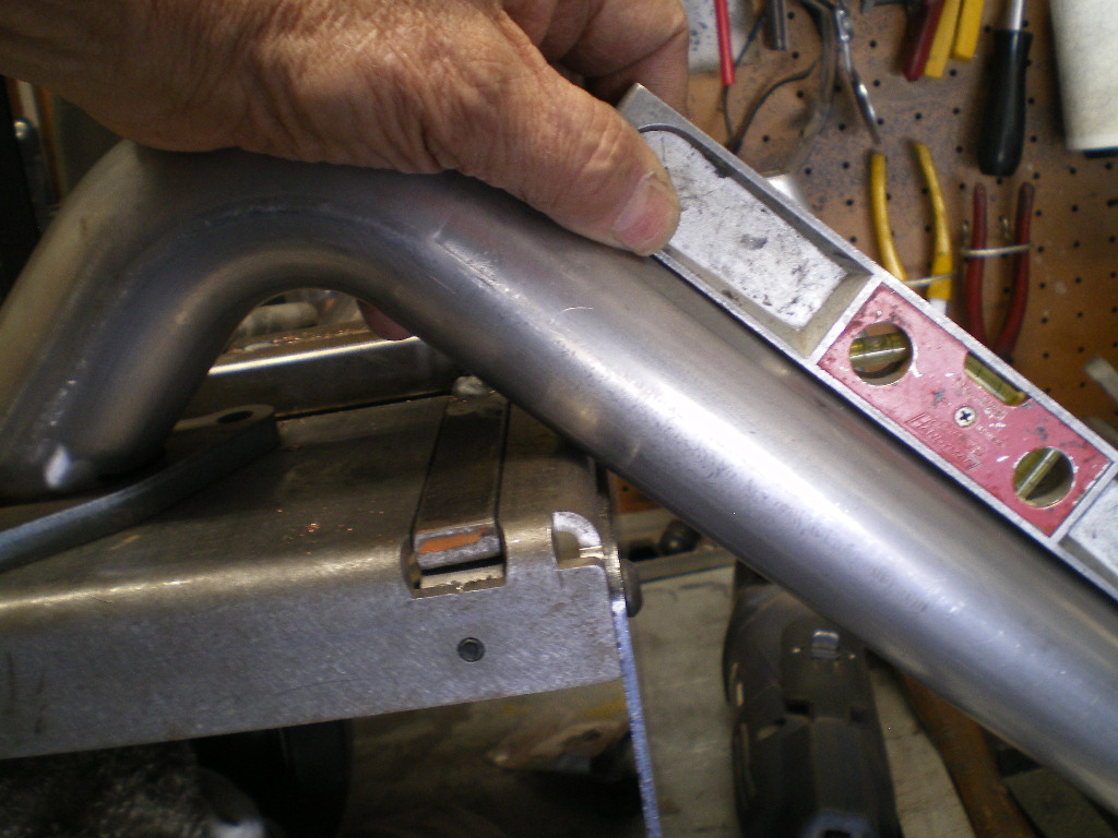
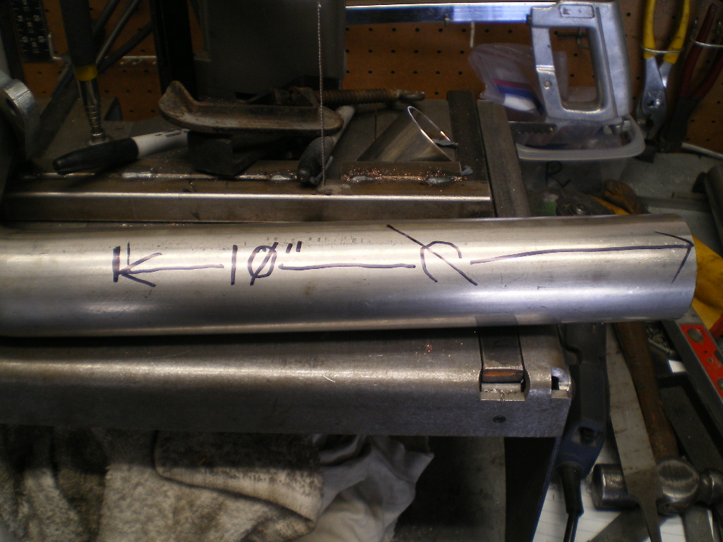
The ends will be drilled with an 1.5" arbor bit at a 110 degree (or 70 degree) angle depending upon which side you're measuring the angle. The end to end measurement taken on the edge of the holes on shortest side will be 30". I suggest you make it a little longer and trim to the final length once you're certain the 30" length will work for you. I'll explain further. Once both ends of the cross member are drilled one side is longer than the other since we are not drilling perpendicular to the pipe. I was distracted by "someone" when I started drilling and measured 30" from the edge of the hole on the long side and screwed that piece up. So, it was a few days before I could get back up to Aircraft Spruce for a 3' piece to correct my boo-boo. Notice that small C clamp on one end. That was ground flat on one side so I could lay my level upon it. Once the first hole is drilled out the cross member is flipped end to end and re-inserted in the tube notcher and checked for level on the C clamp before tightening the tube down in the tube notcher. The C clamp will be on top during both operations. This keeps the drilled ends parallel to one another.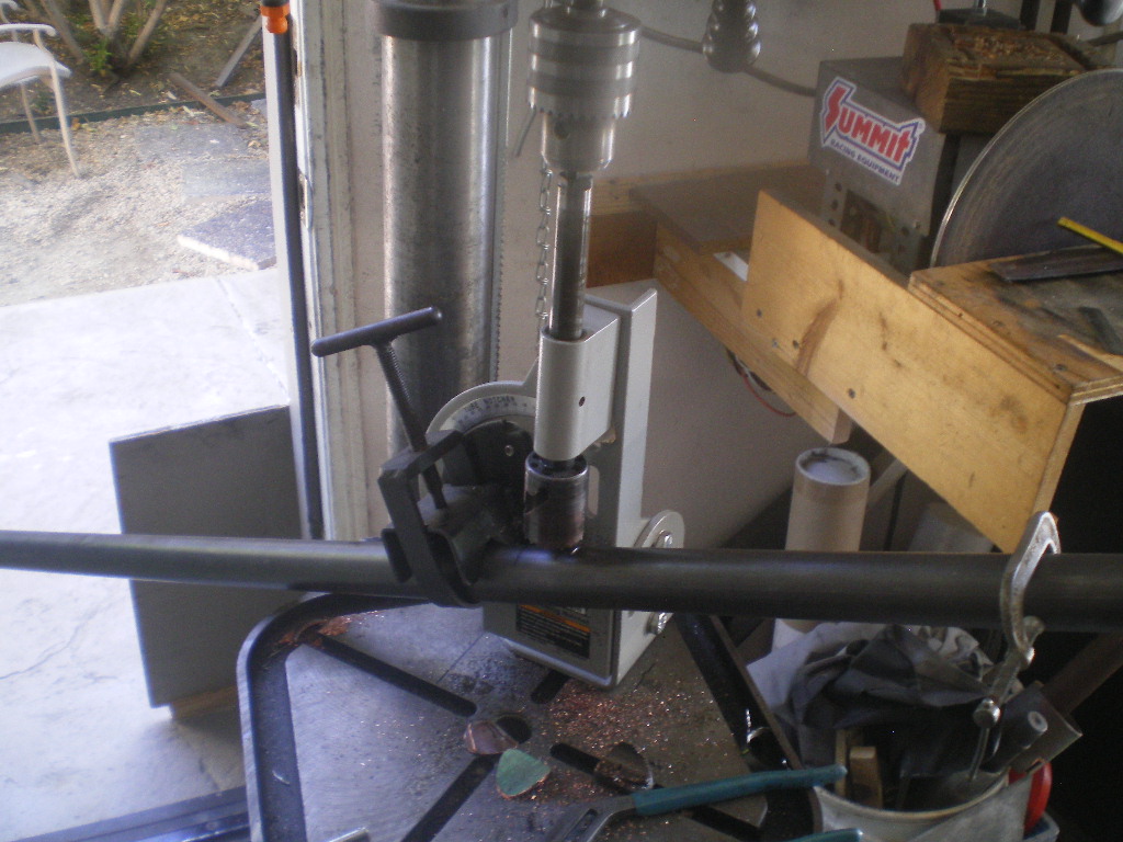
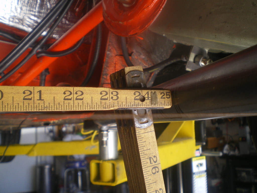
Before going any further I should explain where I got the 30" short edge to short edge dimension. I like to keep the axles centered with the output flanges on the transmission. To achieve this I need to have the center of the cross member 14" from the rear edge of the steel spacer. Just lay your rule on top of the tube and measure back 14". Then roughly draw an 1.5" circle on each side 14" from the center to the edge of the spacer. This will give you reference point for fitting the cross member.If you want your engine to sit closer to the firewall then you will need to adjust this dimension accordingly. Do not place the crossmember further towards the rear unless you want cut up your trunk floor. 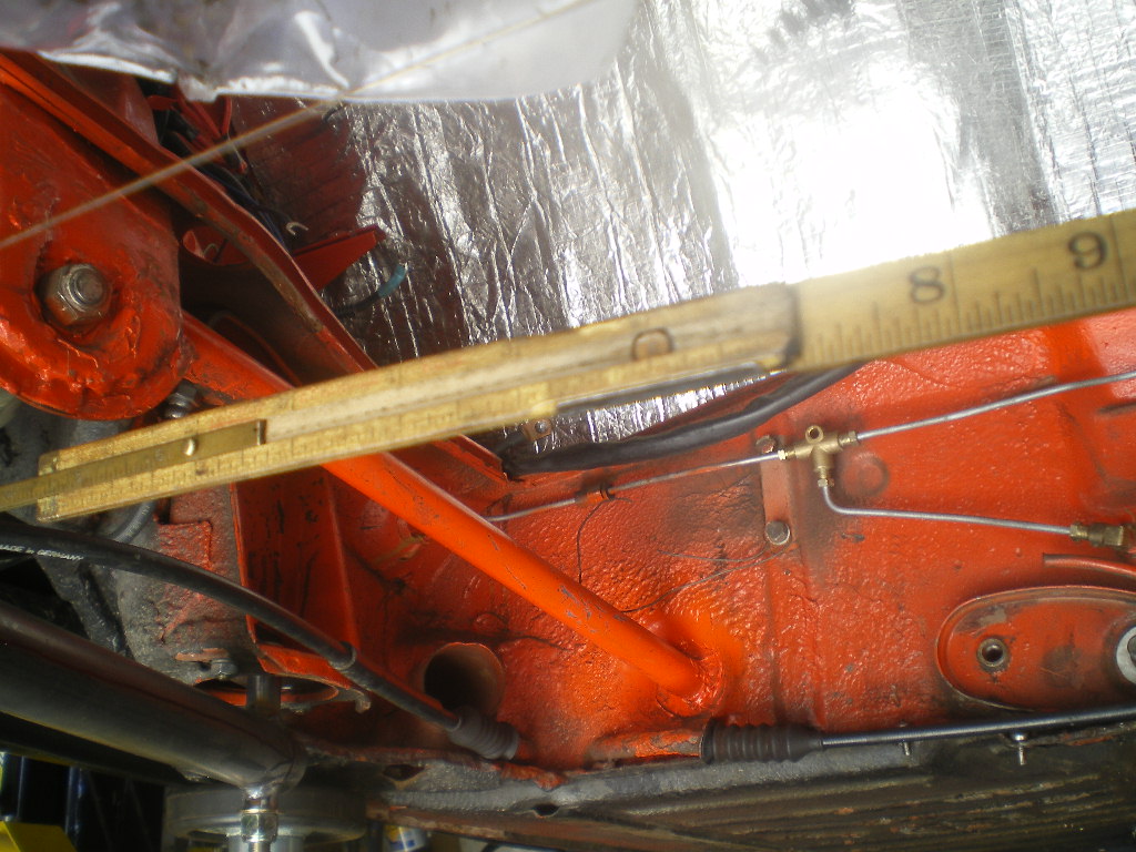
Once you're satisfied with the length you'll want to square it up before welding it in place. I used a string that was strung from the brake calipers. Once the string is taunt measure from the firewall back to either end. Those measurements should be equal; unless the car has some previous shoddy bodywork or Hans had a few beers at lunch. Now check the angle between the string and runners. That should be 110 or 70 degrees depending upon which side of the string you measure. Once secure tack weld both sides, double check your measurements then complete as much of the welds joints as you can.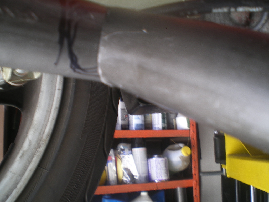
Posted by: 76-914 Jul 22 2020, 07:03 PM
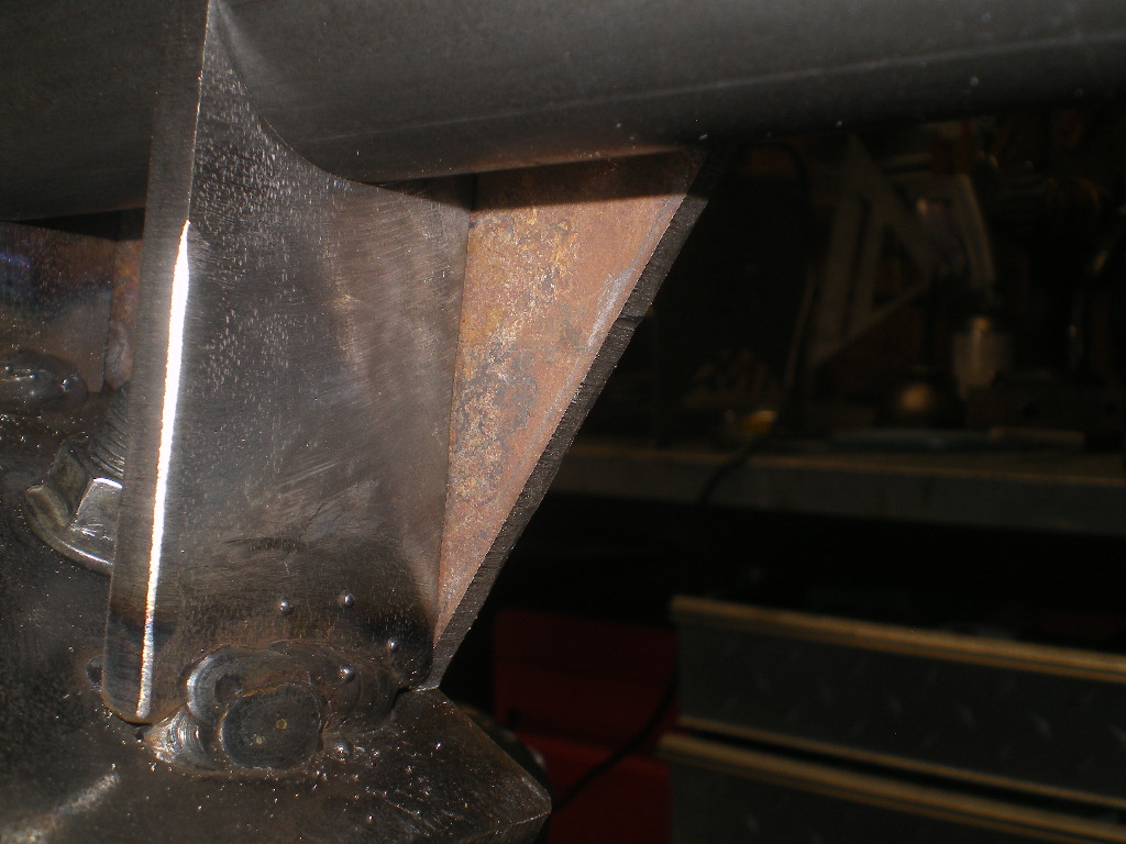
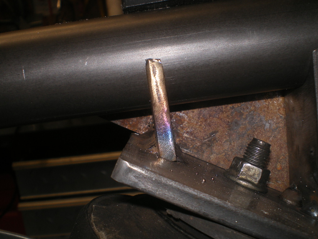
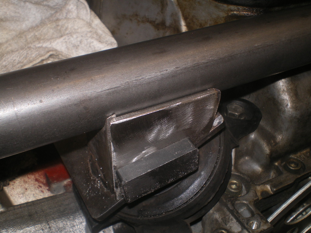
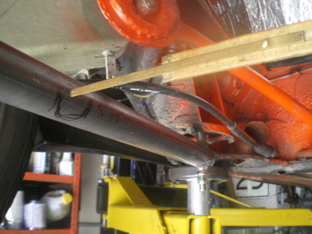
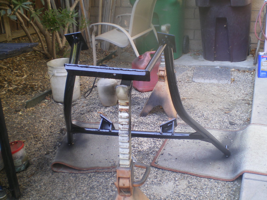
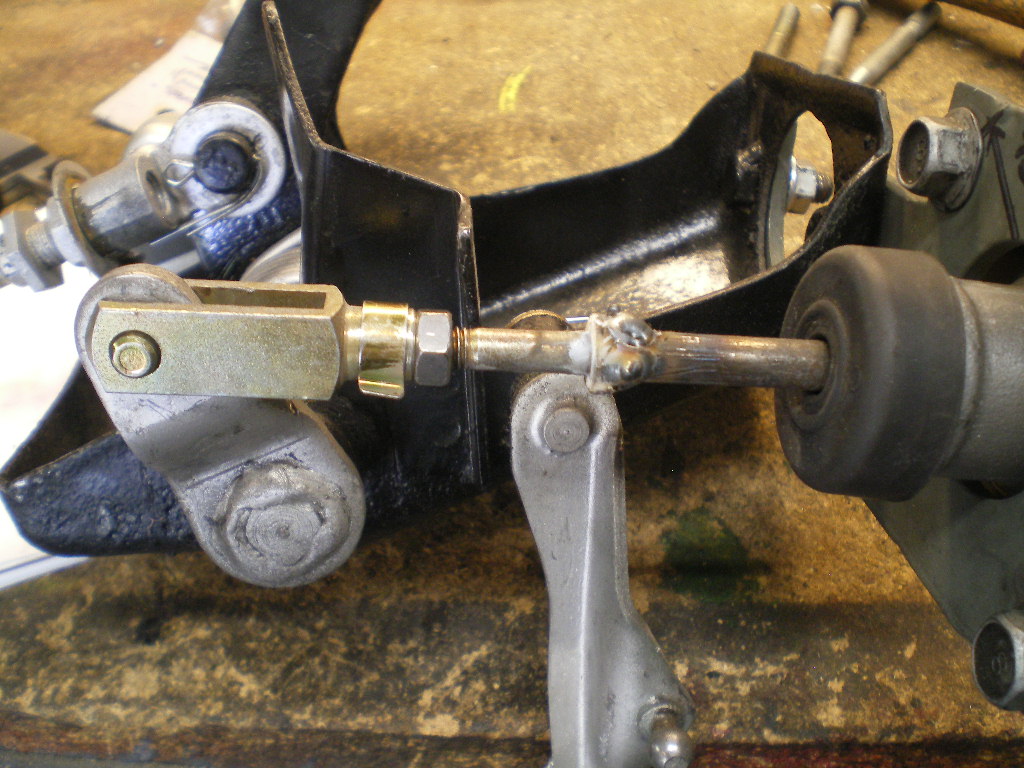
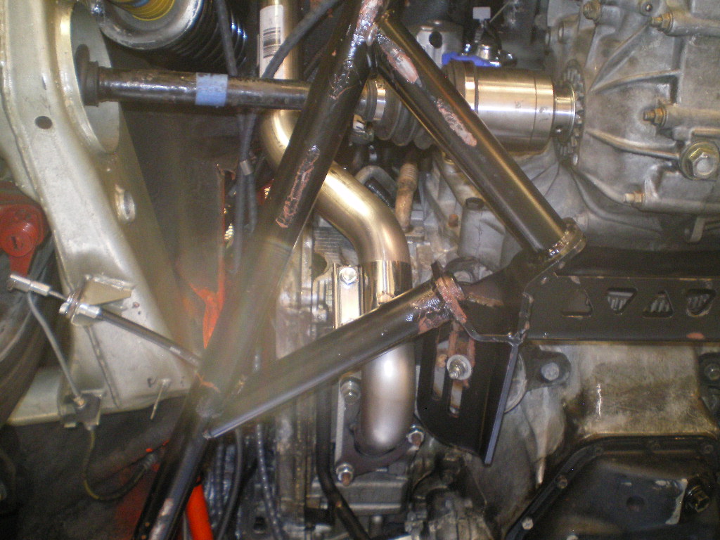
Now remove the cradle from the car and place it upon the motor mounts. Be sure you have all the weld joints on the motor mounts completed at this stage. Place the cross member on the motor mount pieces and check that the cradle is parallel from to back with the engine. Once the cradle is leveled go-ahead and weld it to the motor mounts. It should look something like this once removed from the car.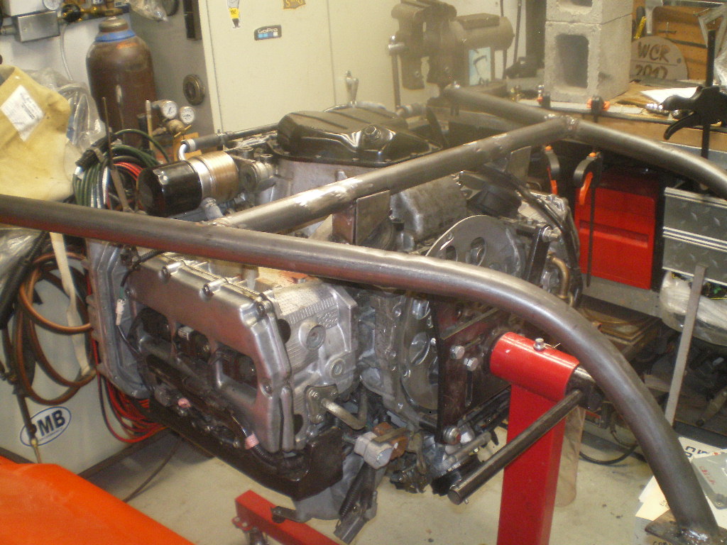
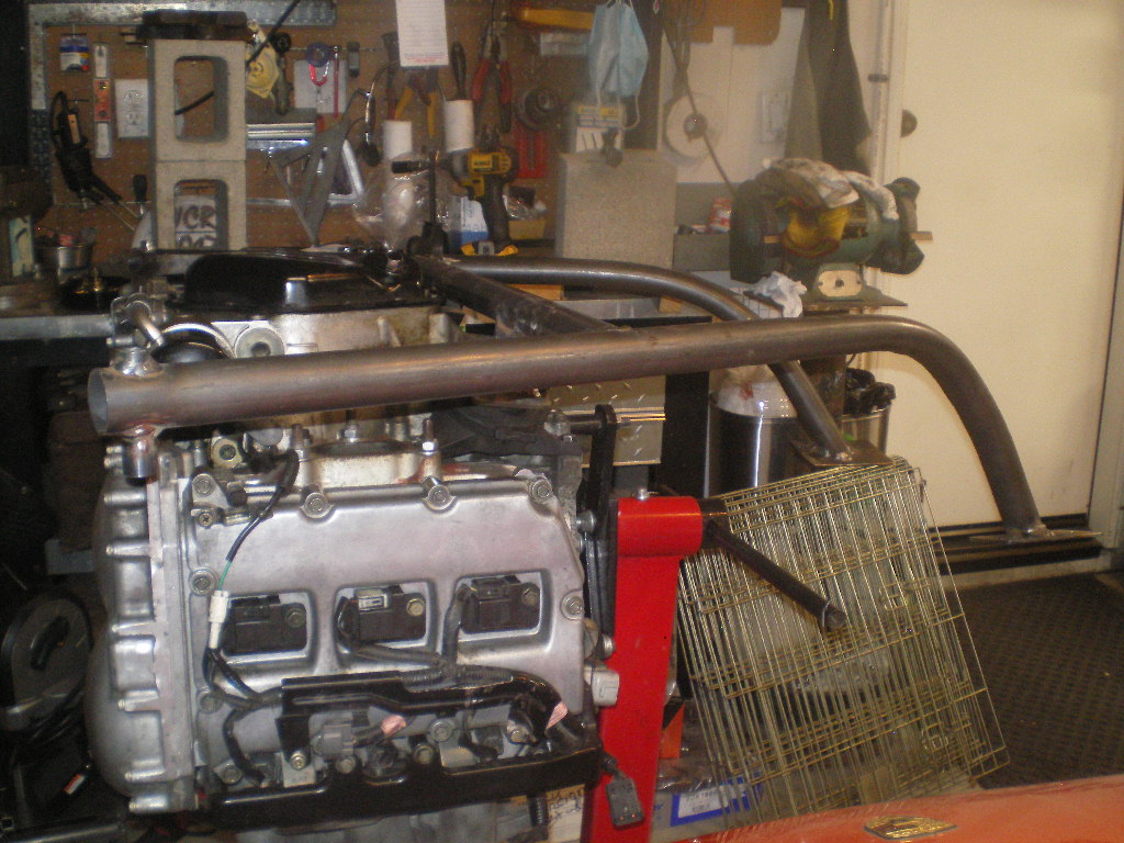
Next up is the transmission carrier. To be continued...................
Posted by: flmont Jul 23 2020, 01:45 PM
Man...That is so perfect !!
Posted by: 76-914 Aug 2 2020, 12:16 PM
Man...That is so perfect !!
You jinxed me Frank! JK, I made a dumb assed mistake and corrections were in order so hence the hiatus. I left off thinking only the trans hanger was left to do. WRONG!
As I installed the clutch after placing the engine in the cradle I discovered the engine was not centered upon the cradle. I had also placed the reinforcement plate on the backside of the mount which would have acted as a scoop for dirt and grime. It should have been placed on the front side AND NOT welded to the tube on the bottom. That would have collected water and led to rust eventually
 How in the Hell did I manage that. It was 1.5" off center. Quien es el burro? So I cut off the mounts to made new ones and I'm glad that I did. I had varied from my original design and encountered a mounting problem as a result. By mounting the U shaped saddles more closely together I took away the length needed for the slot required. The slot allows for the angle of the mounting bolt on the OEM motor mount . I could have mounted the rubber OEM mount on the cradle first then attached the OEM mount to the engine but since I was making another set I now placed the U saddles far enough apart to allow for the lengthening of the slot. In doing so I reduced the process for fabricating the saddles. If you've already cut the U saddles per my earlier description your alright. You just need to mount the OEM mount to the cradle before mounting the engine.
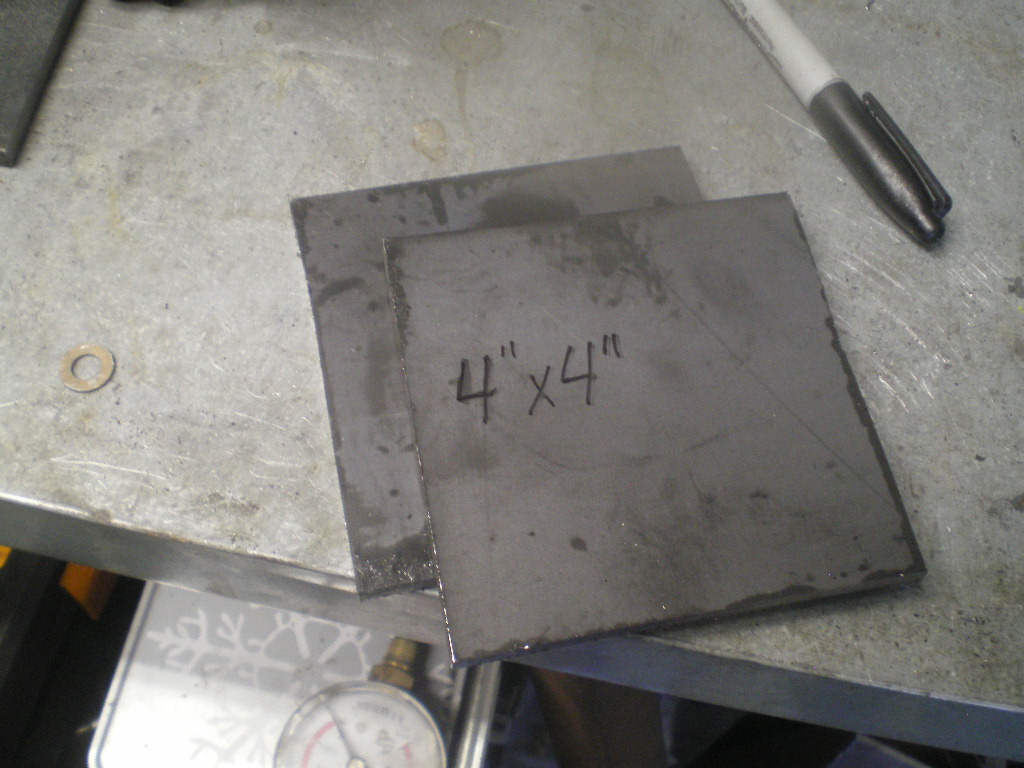
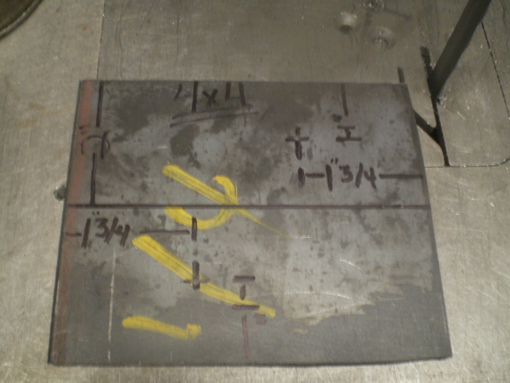
 Looking at the pics below you will see that one 4x4 plate gives you all 4 saddles less cutting and end up being the correct length needed. It also gives a little more material for welding to the tube towards the top of the U.
Welded in place.
The brace correctly positioned facing the front and with a gap that will allow water/sludge to drain and not collect.
Braces in place.
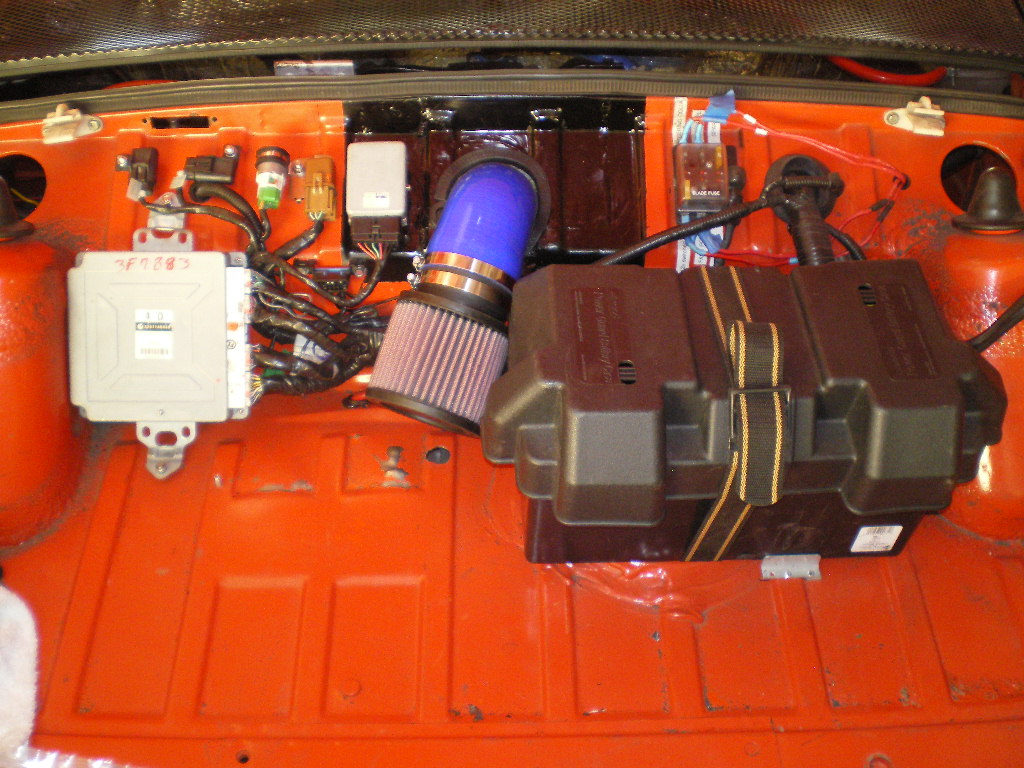
Since we can't see inside the tube I added another element to avoid rusting on the inside. The Schroeder valve allowed me to air test my welds. If air can't seep out moisture cannot seep in.
 You'll need to drill 2 small hole in each arm where the cross brace welds to it in order to get a test on the entire cradle. The Schroeder valve will be removed and plugged later. I thought it could act as an "air tank" but there isn't enough volume to inflate a tire.
  Now back to where I left off before I discovered my
  up. To be continued.................
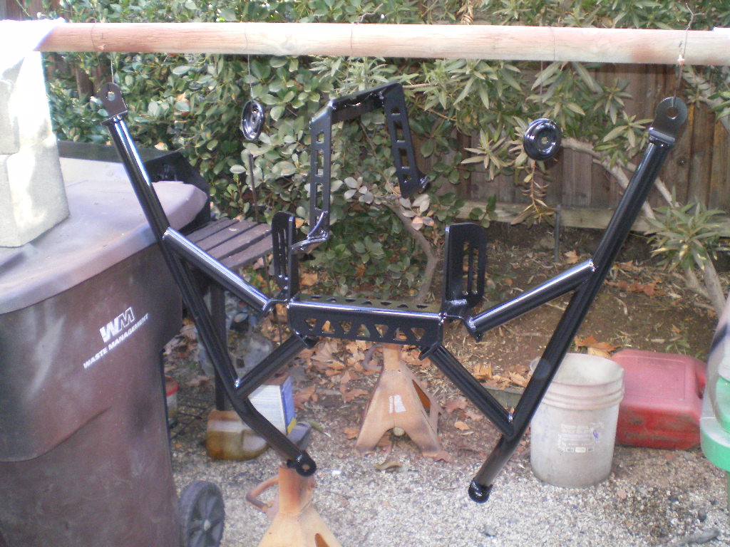
Posted by: 76-914 Aug 24 2020, 09:20 PM
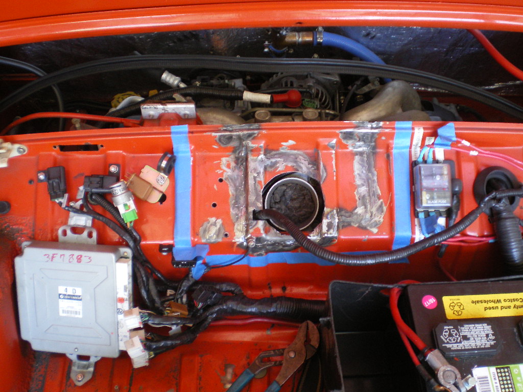
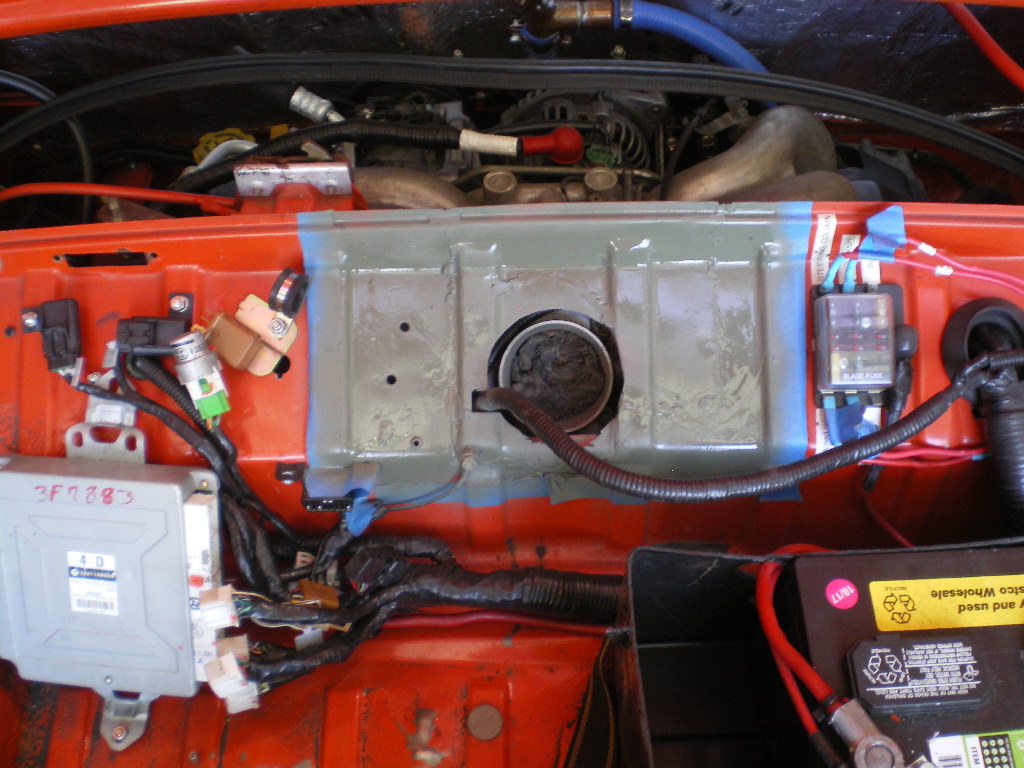
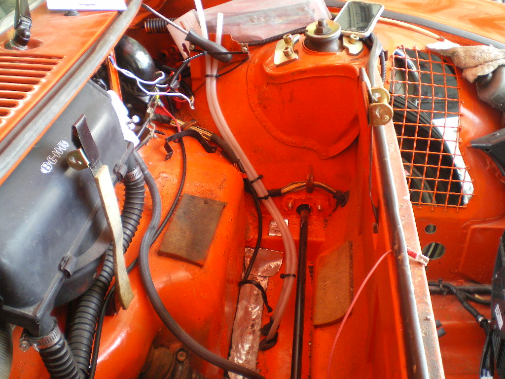
And then there was this Heatwave........There went 3 weeks . On the bright side the cradle is finished sans 2 weld joints and paint. I changed this cradle up a tiny wee bit. If you saw my other build thread you saw that I needed to make a cover in the trunk in order to cover the starter and the clutch slave cylinder. Well, not the entire slave just the actuator arm and the bleed screw. This is the cover on the black conversion.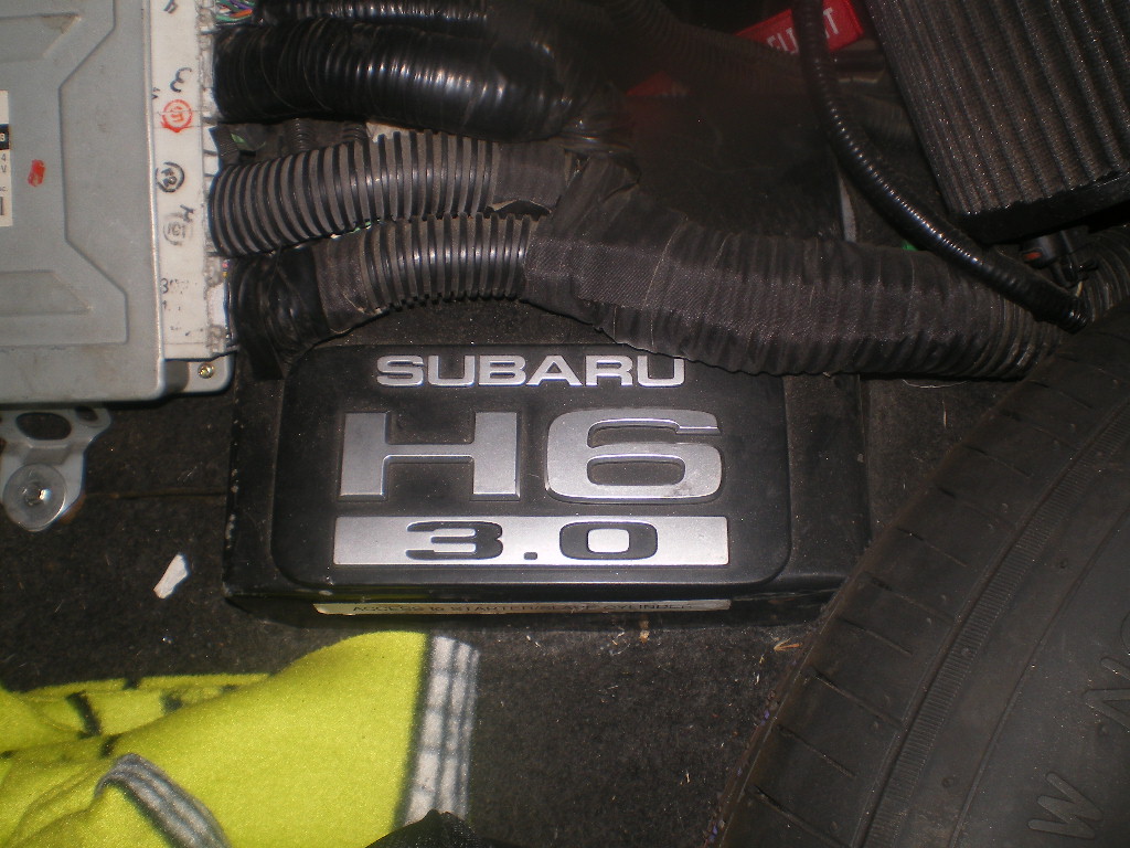
After talking to Bob aka @BIGKAT83 I discovered there is another Subaru starter that is clocked differently thus avoiding a trunk cut for the starter solenoid. Order a starter for a 2002 Outback w/ the 4 cylinder and standard transmission. Thx Bob. I also decided to slide the engine forward 1" giving myself the needed clearance for the slave cylinder. I was dead set on the output flanges being centered with the wheel centers on the first conversion. But truthfully the 1" offset is not noticeable. As with the other conversion I cut the top off the actuator arm where the return spring clips on. It's not needed and gives a little more vertical clearance.
This pic show the clearance between the trunk floor and the starter. 
One showing the clearance between the trunk and bleeder screw on the slave cylinder. Look closely and you'll see an 1/8" hole drilled into the trunk floor. This is to help locate a 1" access hole that I'll drill. It will receive a snap in plug to cover and allow me to bleed the slave w/o getting beneath the car.
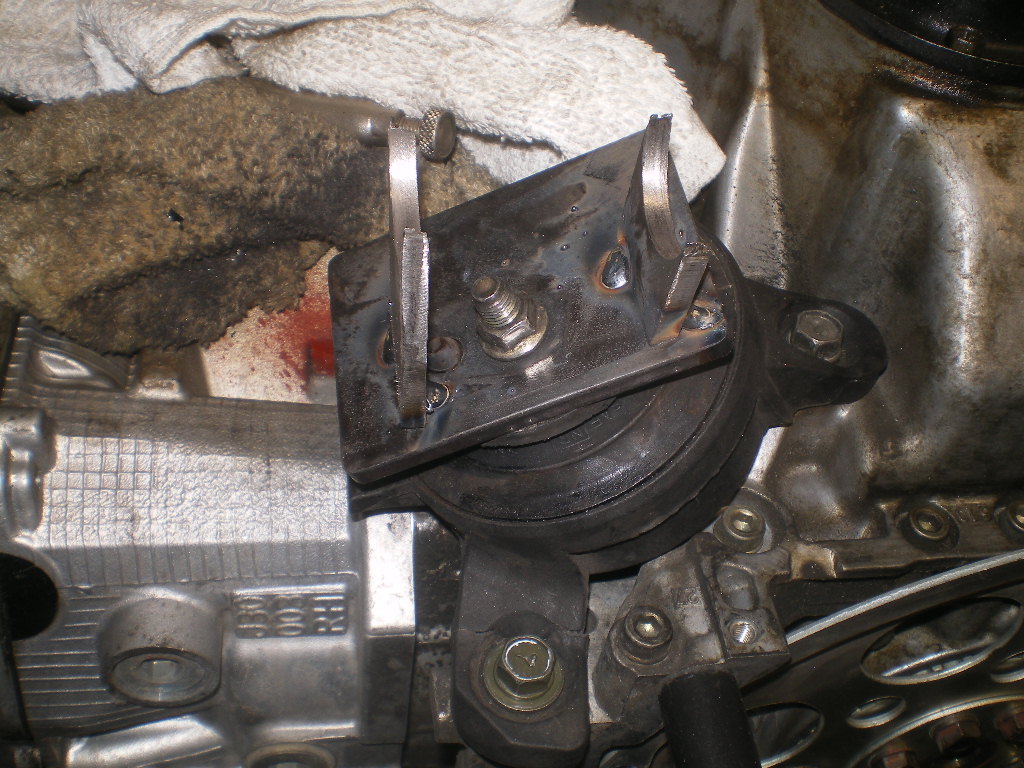
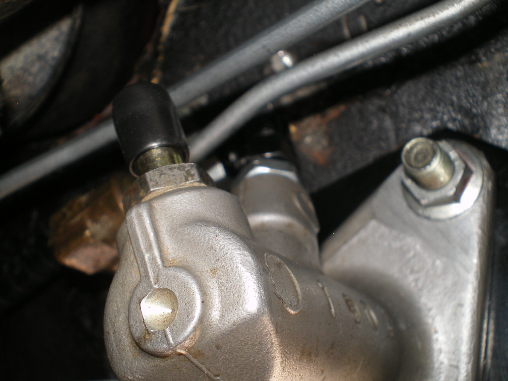
These two show the arm cut down and the clearance.
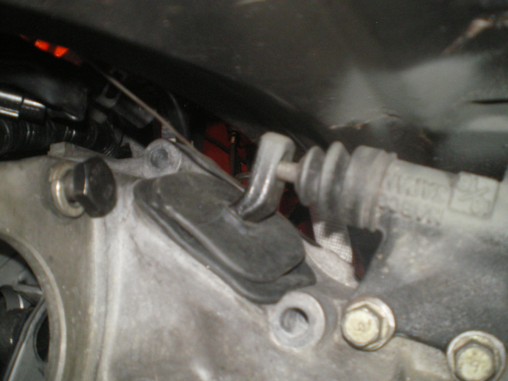
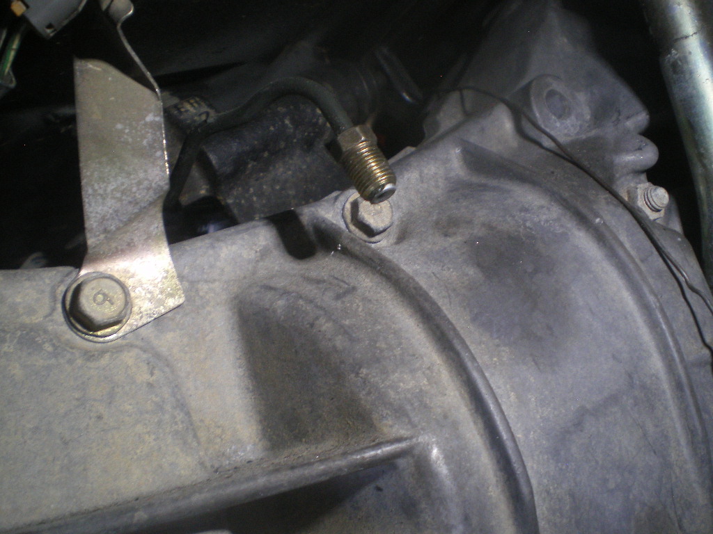
There is a "whatchamacallit" that holds the steel tubing and Banjo bolt at the slave cylinder. I remove this and straighten the tube a bit. Then loosen the nut and flip it over the top of the transmission so that the flare nut is on the passenger side looking down. Anywhere in this general vicinity is good as it will tie into an AN-3 flex hose.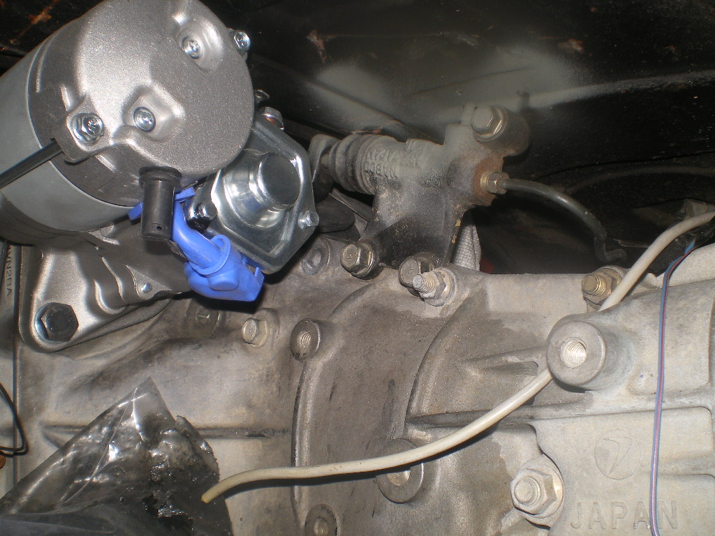
Roll up a paper towel and twist it into the transmission fill tube. It keeps crap out and shows you where to drill the "access hole". At some point I'll get lazy and abbreviate this as an "A Hole".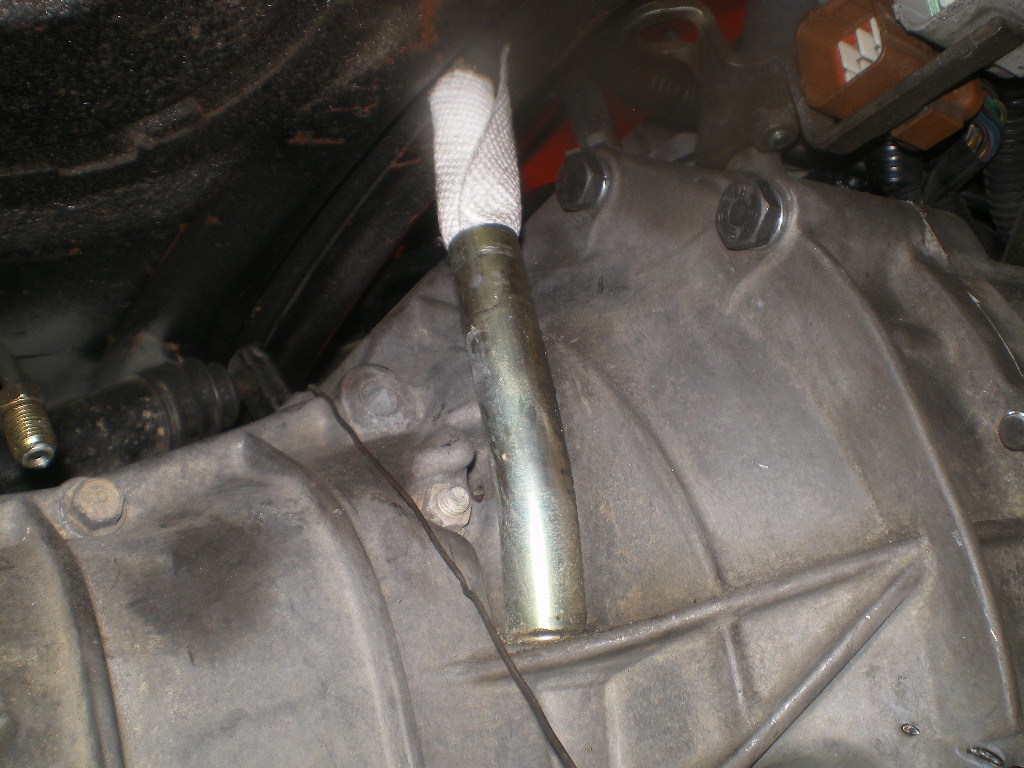
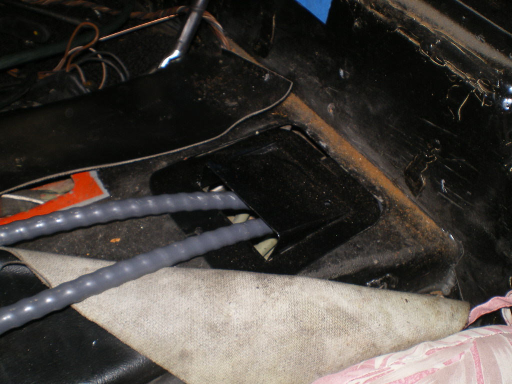
And later you have a place for the dipstick to easily pass through the trunk floor. A very small slit at the edge of the carpet is all that is needed. This pic is from the '73 914 conversion but as you can see there is room to relocate the hole 1" forward. Possibly avoiding a slit on the edge of the carpet. No big deal either way.
Posted by: 76-914 Aug 24 2020, 09:28 PM
Oops. I didn't show any pics of the final cradle part. Not much to it but here it is. Just a 3" x 12" 3/16" plate with a stiffer welded to it and 3/4" .095 chromolly tubes holding it to the main cradle. Its just spot welded on the tubes but I'll finish those two welds before painting it. To be continued...................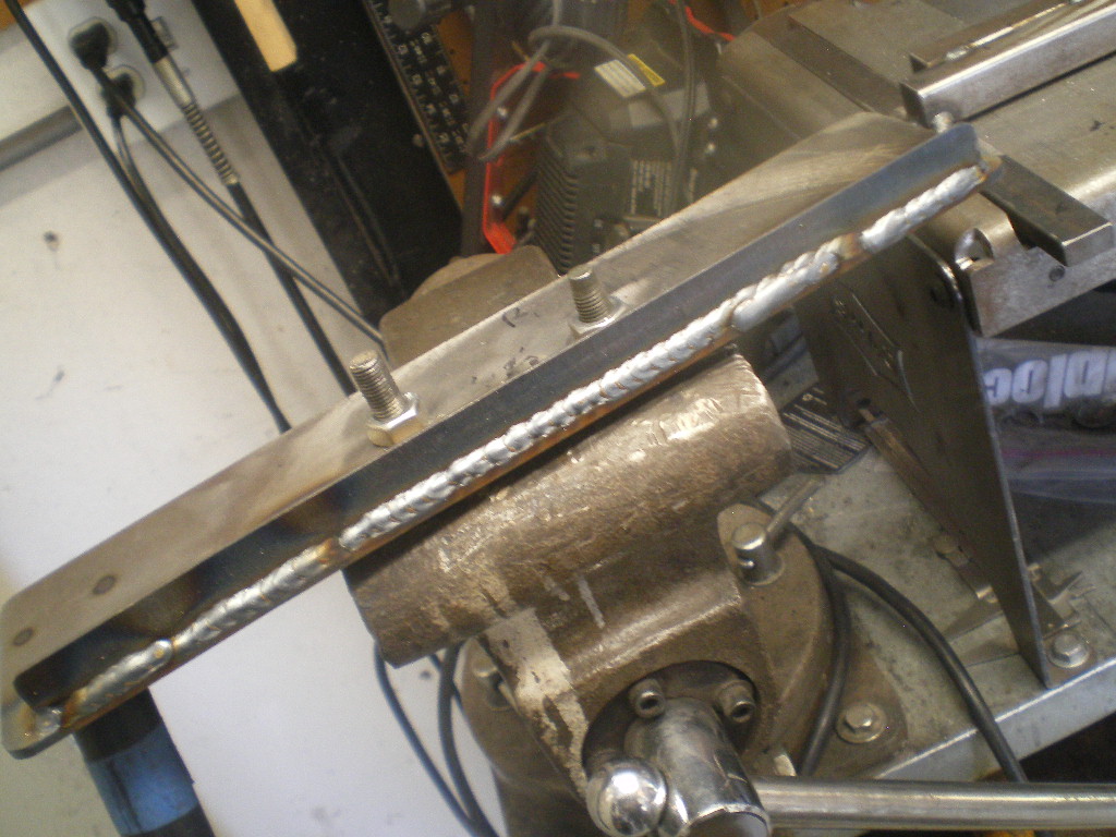
Posted by: euro911 Aug 24 2020, 10:12 PM
Since you drilled holes for the Schroeder valves, you can pop them out & still shoot some Eastwood Internal Frame Coating in there 
Posted by: 914forme Aug 25 2020, 06:39 AM
or other coating of your choice.
Fluid Film or Boeing T9 would be my choice. But even paint would go a long way. I had a buddy who used to restore Sunbeam Tigers, Doug Jennings. He would take his left over epoxy primer before it setup, and just poor it into every hole he could find on the body, and then rotate it around slowly to make sure everything was covered.
Floor of his shop had a nice coverage of epoxy primer also, but he achieved the goal.
Or you can take the easy way out and if it holds pressurized air, it will hold vacuum, draw it down with a vacuum pump and never worry about it again, or at least as long as you have it. Depending on wall thickness, I doubt you would see significant internal rust that would cause a larger issue.
Posted by: ValcoOscar Aug 25 2020, 09:48 AM
Kent-

I'm here for you if you decide to bead blast, epoxy paint or powdercoat. I can even stress relieve to ensure it doesn't twist over time.
LMK...
Oscar
Posted by: 76-914 Aug 25 2020, 05:03 PM
Kent-
I'm here for you if you decide to bead blast, epoxy paint or powdercoat. I can even stress relieve to ensure it doesn't twist over time.
LMK...
Oscar
Thx Oscar. I just got back from Tractor supply with a qt of black. Wish I'd known about your ability to stress relive professionally. I relieved the weld joints w/ Oxy/Acy; the poor boy's way.
Posted by: 76-914 Aug 25 2020, 05:05 PM
Since you drilled holes for the Schroeder valves, you can pop them out & still shoot some Eastwood Internal Frame Coating in there
or other coating of your choice.Fluid Film or Boeing T9 would be my choice. But even paint would go a long way. I had a buddy who used to restore Sunbeam Tigers, Doug Jennings. He would take his left over epoxy primer before it setup, and just poor it into every hole he could find on the body, and then rotate it around slowly to make sure everything was covered.
Floor of his shop had a nice coverage of epoxy primer also, but he achieved the goal.
Or you can take the easy way out and if it holds pressurized air, it will hold vacuum, draw it down with a vacuum pump and never worry about it again, or at least as long as you have it. Depending on wall thickness, I doubt you would see significant internal rust that would cause a larger issue.
Good suggestions from the both of you. Here in this climate I should be OK au natural.
Posted by: 76-914 Aug 25 2020, 05:10 PM
I did get it in primer this morning. Hopefully I can shoot a little paint before it becomes too hot tomorrow. 
Posted by: 76-914 Aug 26 2020, 03:00 PM
Dressed her up with a new coat this morning. I'll let it bake in the Sun for a few days before I saddle it back up. 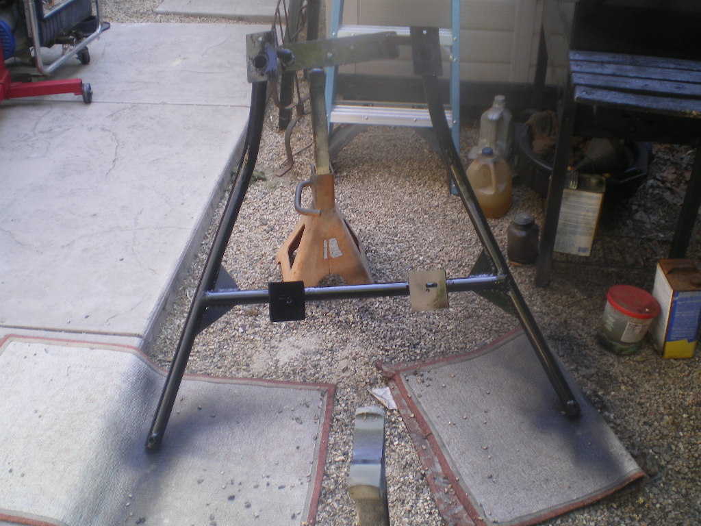
Posted by: 808 WRX Aug 26 2020, 03:22 PM
 Looking good!
Posted by: 76-914 Aug 27 2020, 03:14 PM
Thx, They're like women."They all look good when you ain't feeding 'em"! Now back to our irregular non-scheduled program.
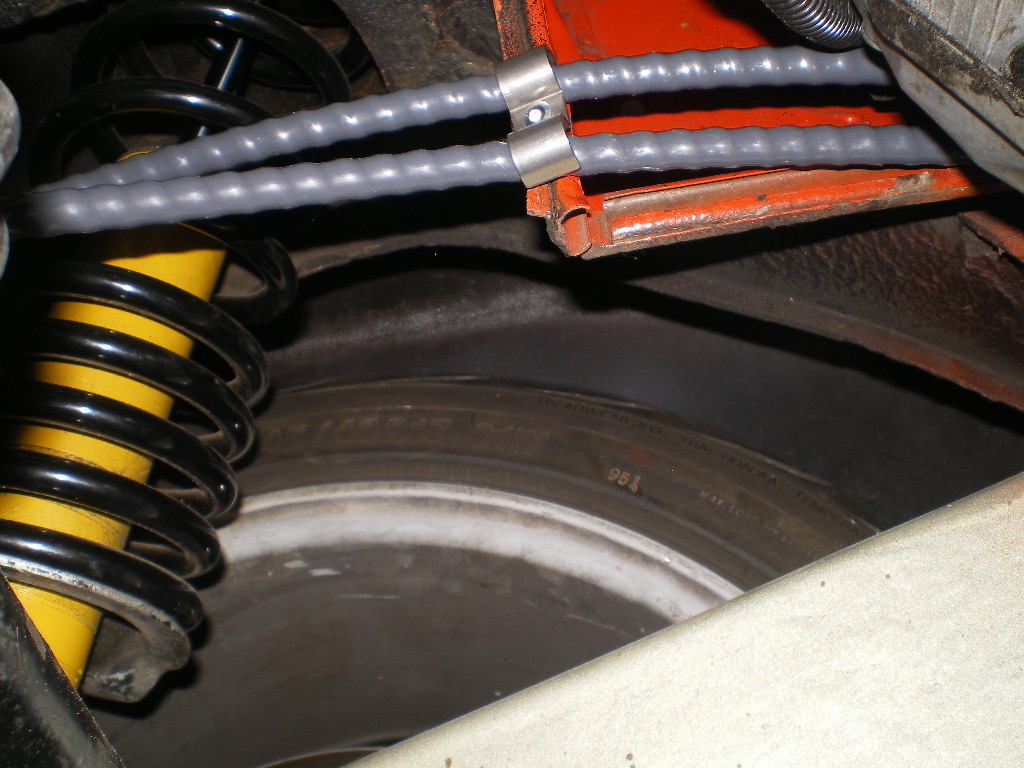
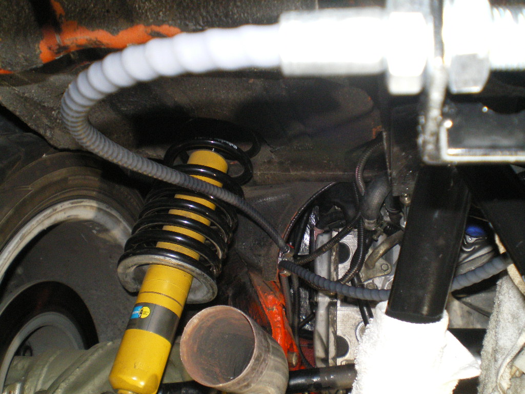
While Lady Drivetrain sits patiently in the corner awaiting her shiny cradle: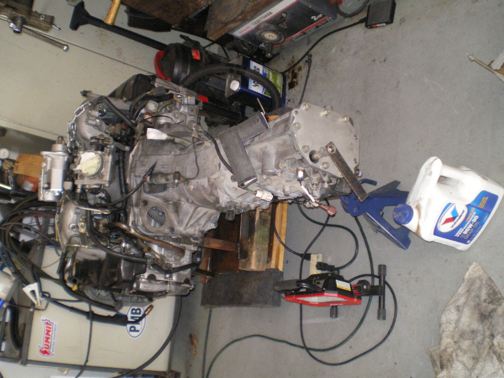
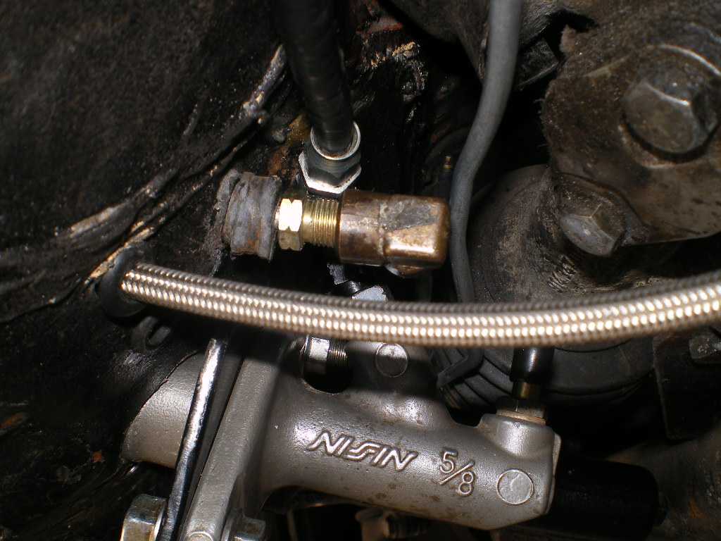
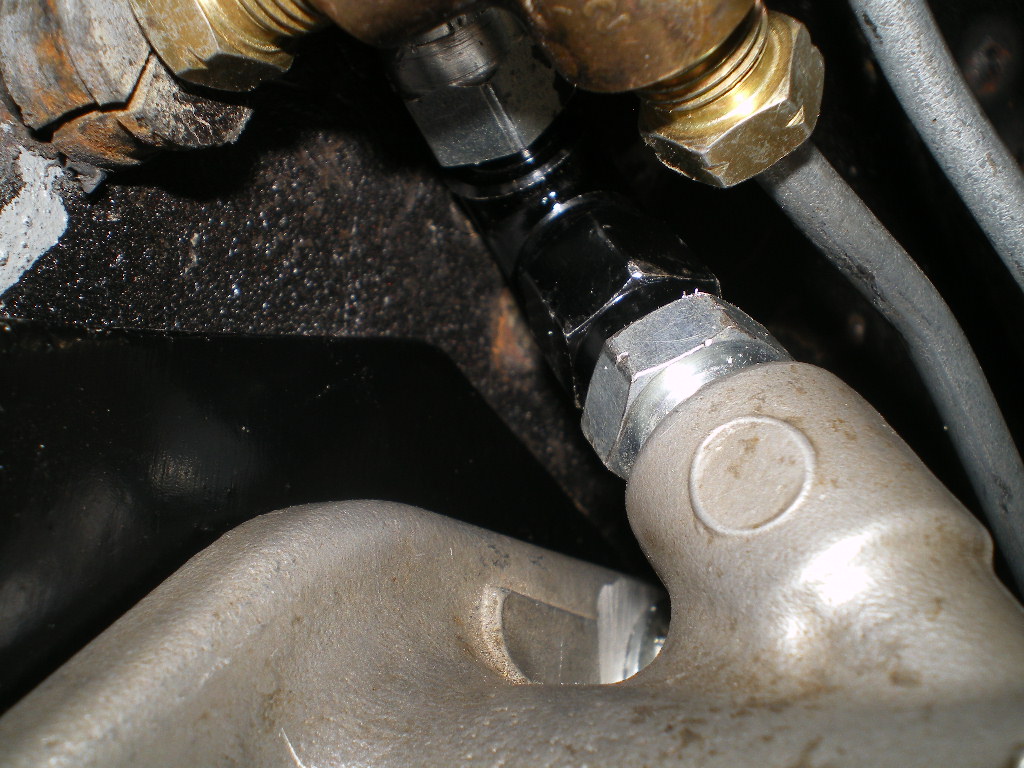
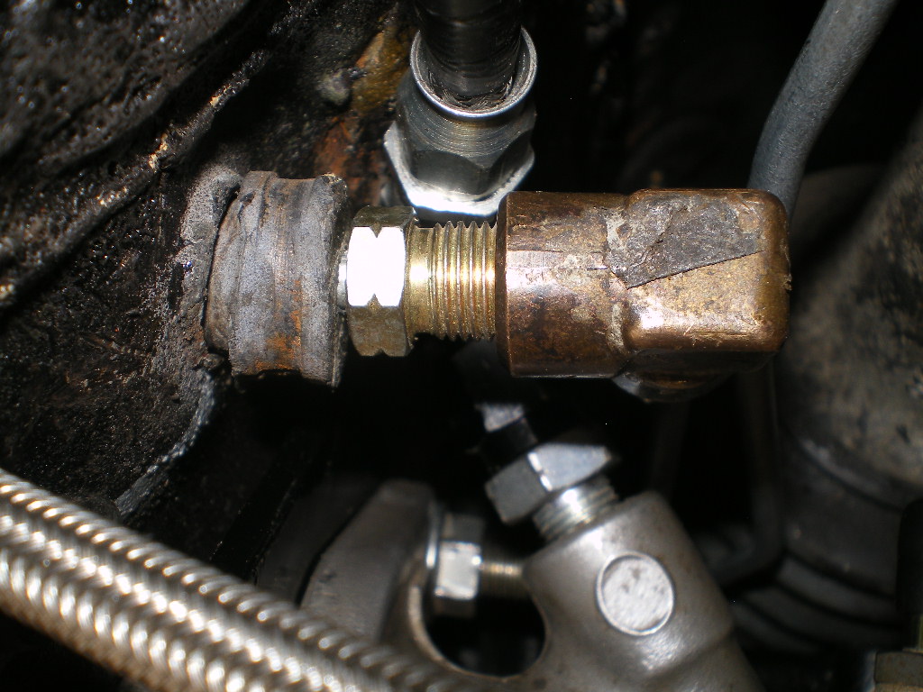
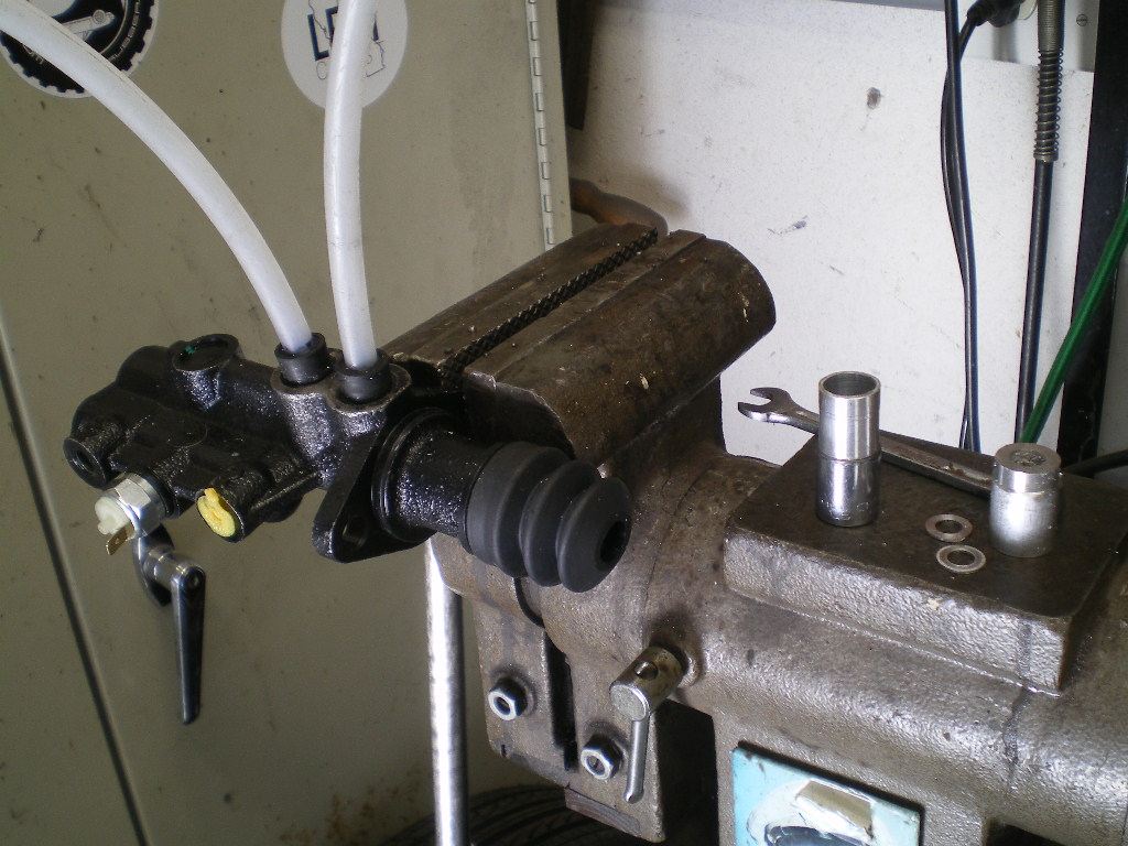
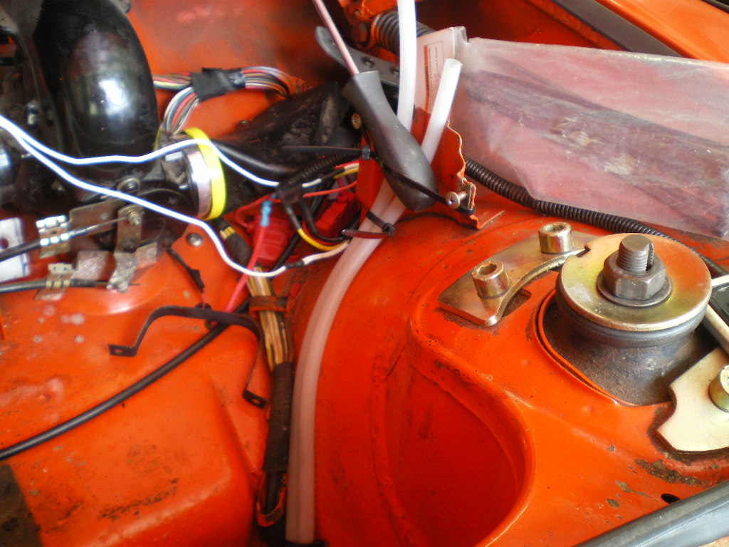
I wanted to get a better shot of the slave cylinder line that is straightened and moved to the psg side.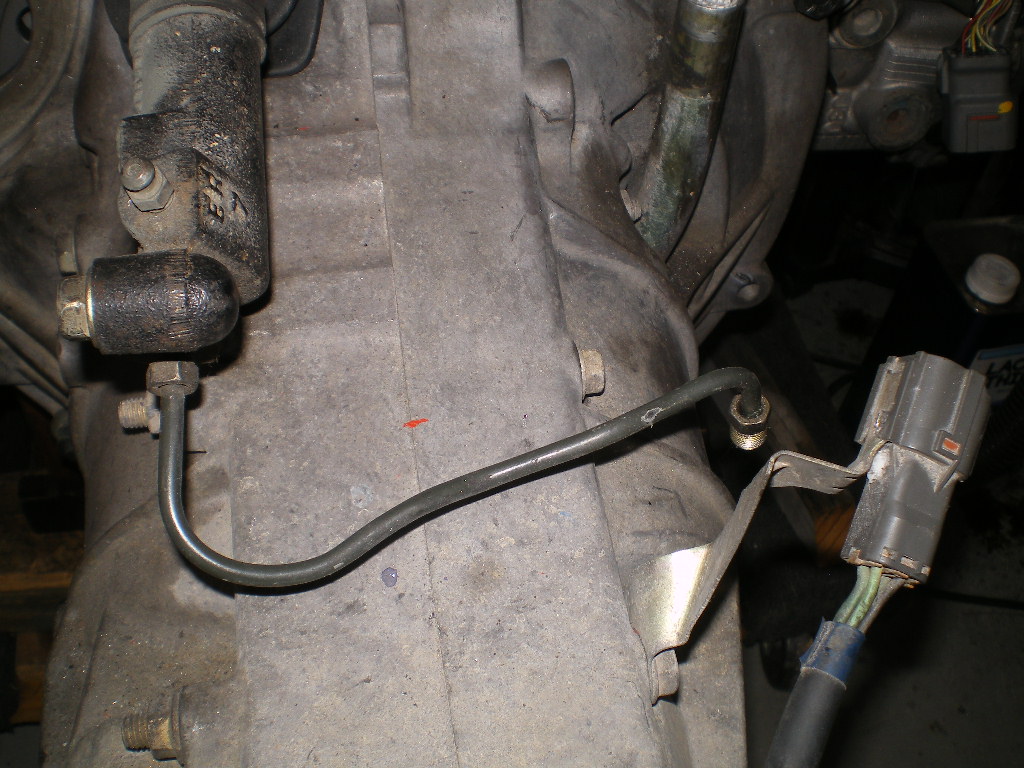
And this is the removed part that I referred to earlier as a Whatchamacallit.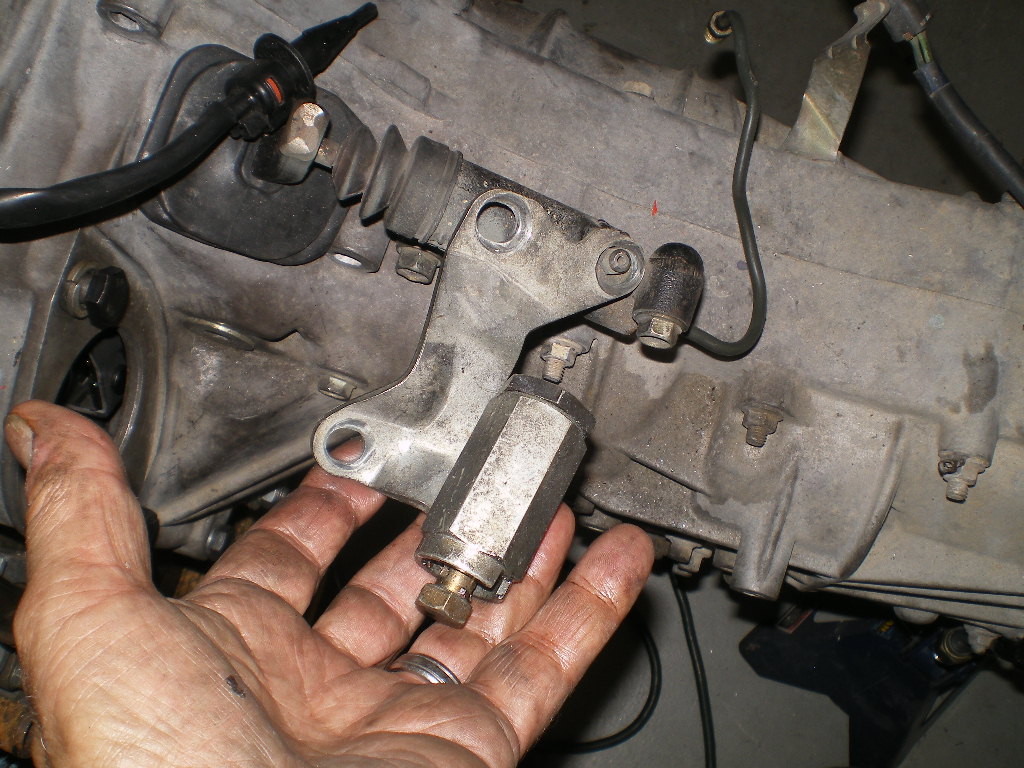
Ans speaking to the transmission: If you plan to use a neutral safety switch, this is the one you'll need. Remove the old one which is N/O in neutral and replace it with this one which is N/C in neutral. Install it in series with the ground on the starter relay. I'll get into that later.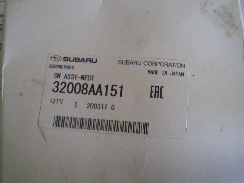
Also, I wanted some real numbers on how much gear oil is needed after converting the TY75 to front wheel drive. I'd heard 1 xtra qt but I'm going to find out. I took a 1 gal can, opened it up and sat the center differential some bearings and washers (which you can't see) on the bottom and this one short shaft with it's bearing then filled the can with used motor oil to a mark on the inside of the can. It is roughly the height of the center differential.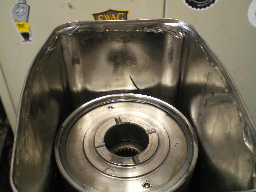
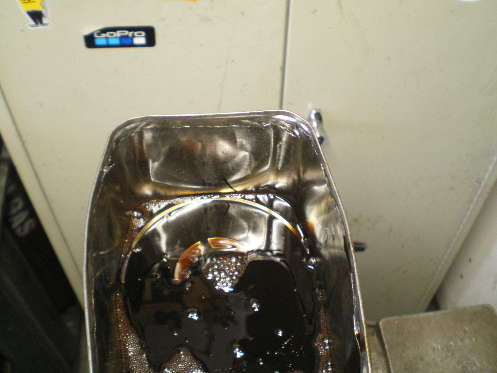
Then let it sit a few minutes so the bearings and other crevices could fill with oil.Next I removed the parts and let them begin to drip the oil back into the container. 
Tomorrow AM I will measure how much additional oil it takes to fill it to that line. Then add the one shaft (pictured below) I couldn't fit with the other parts and add oil to another mark which I'll add above the old one. Once I've determined the additional volume that was required I'll measure the amount the nose cone held and subtract that amount. I'll probably discover that it is 1 qt. indeed and that I've managed to piss off a hour ,once again.
Attached image(s)

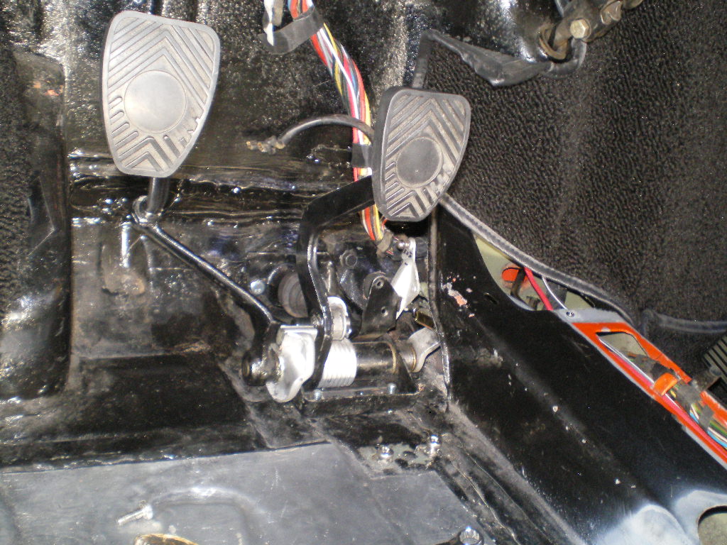
Posted by: 76-914 Aug 27 2020, 03:33 PM
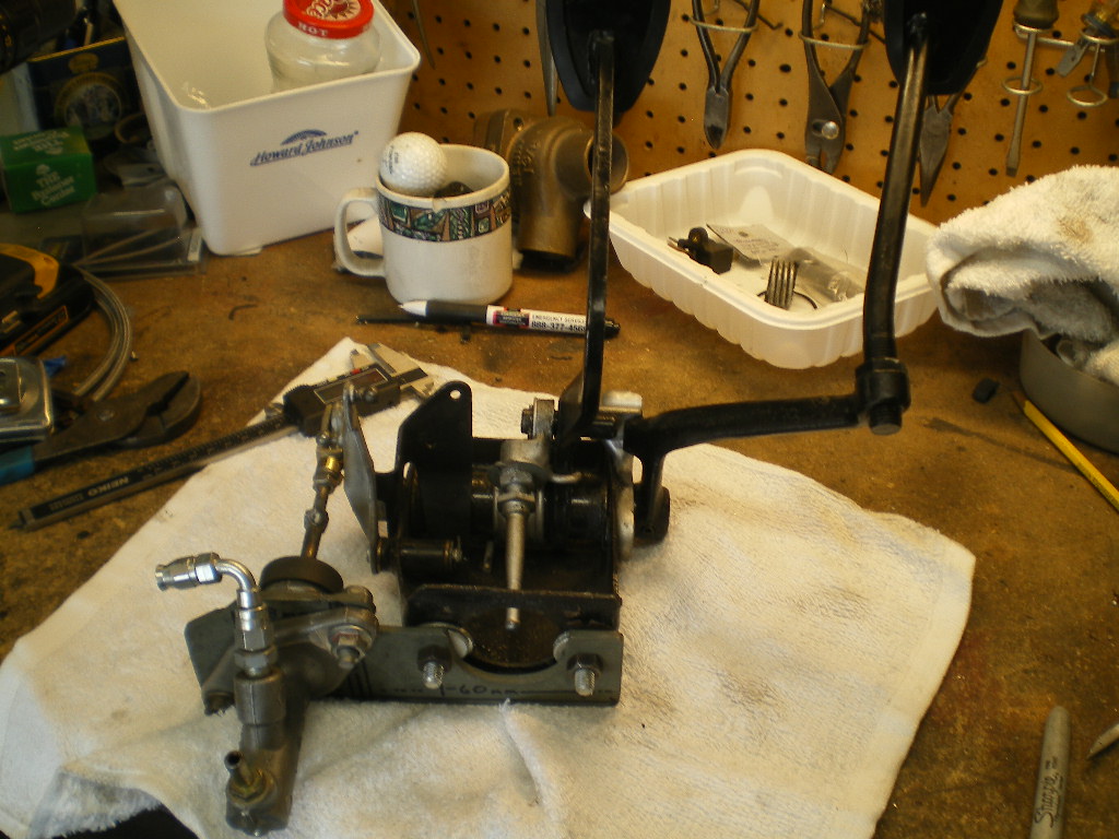
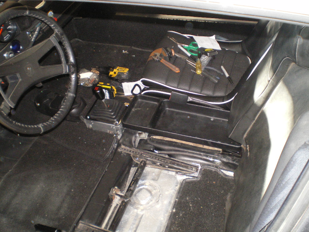
So, before the afternoon heat crept in I was able to knock out a few more items. First the pedal assembly was removed and I installed the adapter plate and MC on it.Much more to do on this later. I'll also get into a little more detail on the adapter plate.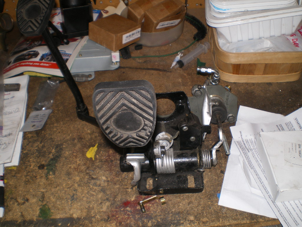
Won't be needing this anymore.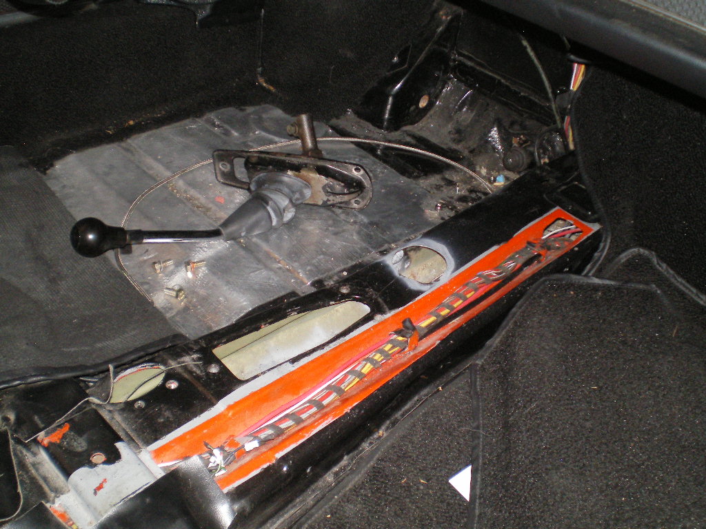
Nor this.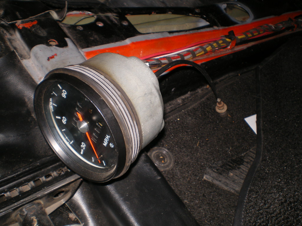
After removing the mechanical clutch cable I inserted the AN3 Aeroquip hose, for the hydraulic clutch, in the clutch cable's old tube. To be continued................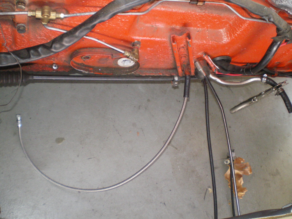
Posted by: rmarx Sep 11 2020, 05:41 PM
Great thread! Thank you for posting all the details. I am doing an EZ30d® and WRX 5 speed conversion
myself. What are you going to use for CV joints and half shafts?
Thank you.
Bob Marx
Posted by: 76-914 Sep 16 2020, 05:37 PM
Sorry I'm late getting back to you @http://www.914world.com/bbs2/index.php?showuser=7784 . Just got back yesterday from a 2000 mile trip to CO and back. I'll be using the 914 shafts with one 914 CV joint and one Subaru CV on each shaft. I cut the shaft down to the length I want then send them to Dutchman Axle (503-257-6604) to have the cut end re-splined for the Subaru CV. I should be detailing that sometime next week.
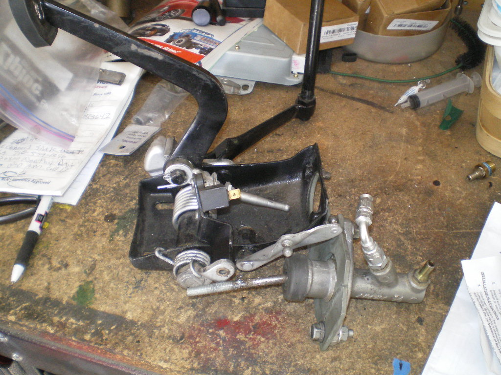
Now back to the pedal cluster conversion. First remove the roll pin from the clutch pedal.
Then slide the shaft out and remove the return spring from the shaft. It is on the opposite end of the shaft from the roll pin. Now reassemble the shaft and re-insert the roll pin.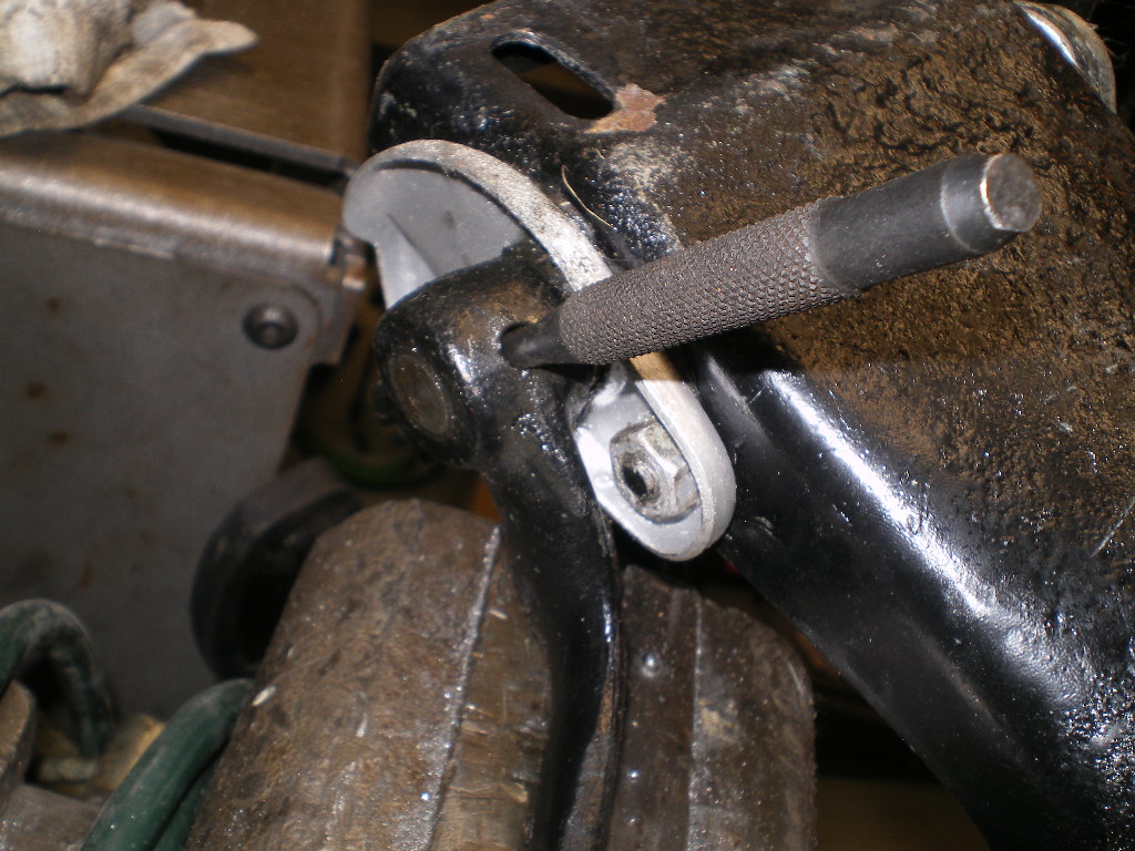
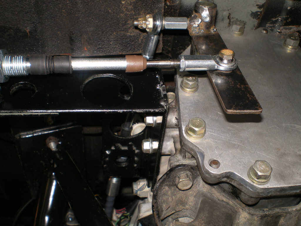
This is where I differ from the last build. I am using the OEM fork and clip that previously attached to the clutch cable. Pictured below is the bolt I welded to the Honda master cylinder push rod. I determined where to cut the push rod by threading the bolt into the fork leaving myself room to adjust to or fro.I them drilled a very shallow hole in the head of the bolt and inserted the cut end of the push rod.
Next I cut the spot welds on the 2 bolts that are attached to the cluster which the brake master cylinder bolts to. They are too short once the adapter plate is added. There are 2 spot welds on each bolt. Using a Dremel tool you only need to cut the the better part of one spot weld on each bolt.
Then place an old socket over the bolt head and squeeze it in a vise until the other spot weld pops. Sometimes you can hammer them out but it's easier with a vise. Replace the old ones with new bolts that are 12-14mm longer than the old ones.
Finally you need to trim the accelerator pivot arm for clearance. See pic below.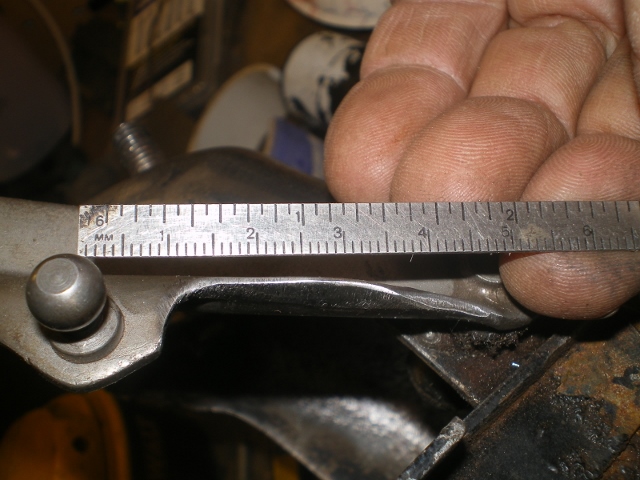
Attached image(s)
Posted by: Steve Sep 16 2020, 07:05 PM
Impressive skills Kent!! As Ferdinand said "nobody made the sports car I wanted, so I made it myself" or something like that....
Posted by: rnellums Sep 16 2020, 07:44 PM
Great work Kent. When I rebuilt my pedal assembly I also added a new return spring for the clutch pedal to return it to upright.
Century spring PN TO-1026. I have about 10 spares. If your interested in one I’ll drop it in the mail!
Posted by: euro911 Sep 17 2020, 12:04 AM
You master fabricator, you
Posted by: mgp4591 Sep 17 2020, 10:48 AM
Great work Kent. When I rebuilt my pedal assembly I also added a new return spring for the clutch pedal to return it to upright.
Century spring PN TO-1026. I have about 10 spares. If your interested in one I’ll drop it in the mail!
That's a good add to the pedal cluster. If you want to lighten your inventory, I'd love to help you out! Do you have any pics of what it looks like installed?
Posted by: ValcoOscar Sep 17 2020, 11:24 AM
Kent-
You are officially a WORLDLY MacGyver! 


Can't wait to resume our Sat morning breakfasts @ Richies 
Carry on...
Oscar
Posted by: 76-914 Sep 17 2020, 07:19 PM
Impressive skills Kent!! As Ferdinand said "nobody made the sports car I wanted, so I made it myself" or something like that....
Great work Kent. When I rebuilt my pedal assembly I also added a new return spring for the clutch pedal to return it to upright.
Century spring PN TO-1026. I have about 10 spares. If your interested in one I’ll drop it in the mail!
You master fabricator, you
Great work Kent. When I rebuilt my pedal assembly I also added a new return spring for the clutch pedal to return it to upright.
Century spring PN TO-1026. I have about 10 spares. If your interested in one I’ll drop it in the mail!
That's a good add to the pedal cluster. If you want to lighten your inventory, I'd love to help you out! Do you have any pics of what it looks like installed?
Kent-
You are officially a WORLDLY MacGyver!
Can't wait to resume our Sat morning breakfasts @ Richies
Carry on...
Oscar

Posted by: 76-914 Sep 22 2020, 01:48 PM
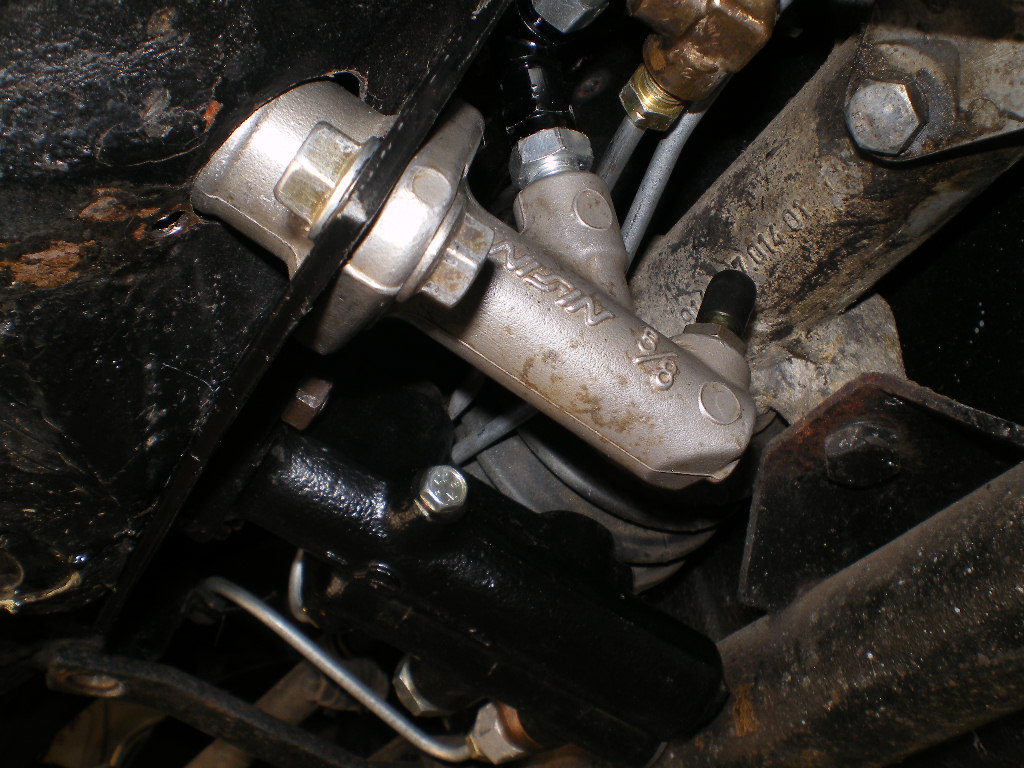
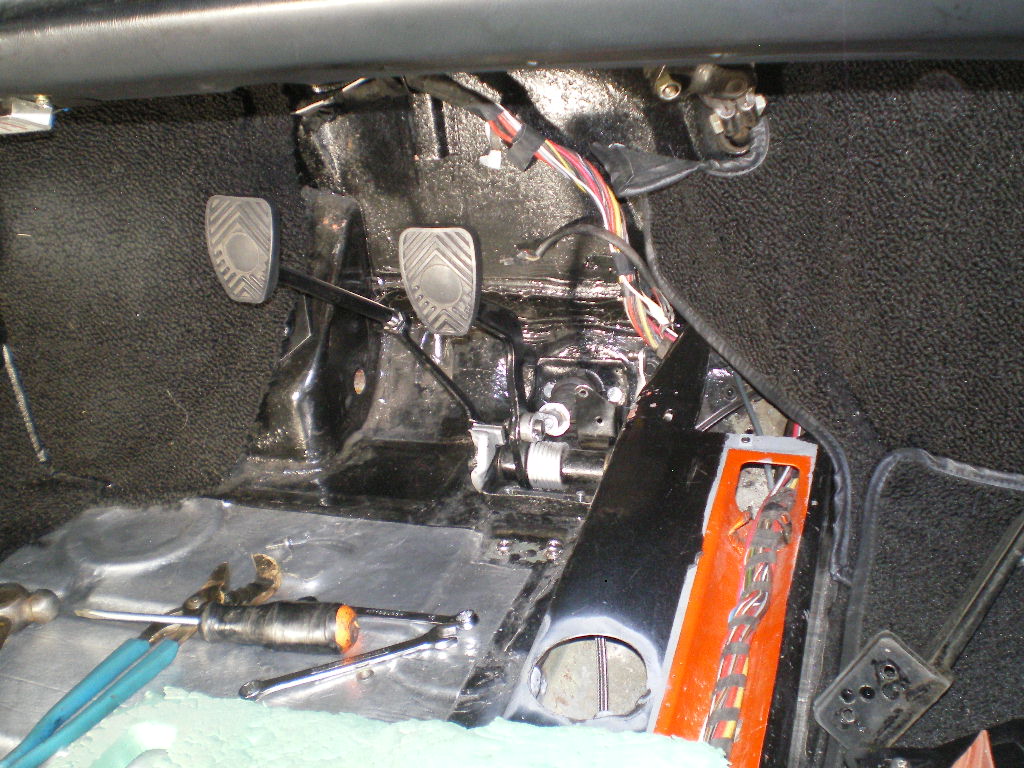
Picking up where I left off. Here is a pic of the pedal cluster before it's re-installed. I did not use the AN3 90 pictured as it was too tight against the bulkhead. I did not run into this on the 73 conversion so I was surprised when it didn't fit as planned. This car had some metal work done to it previously and I suspect something changed slightly during that process. 
Here are several pics from the underside of it mounted in place. You can see the black AN3 swivel 90 that I used in place of the one in the other pic's. It was tighter than Socks on a Rooster but fit nicely. 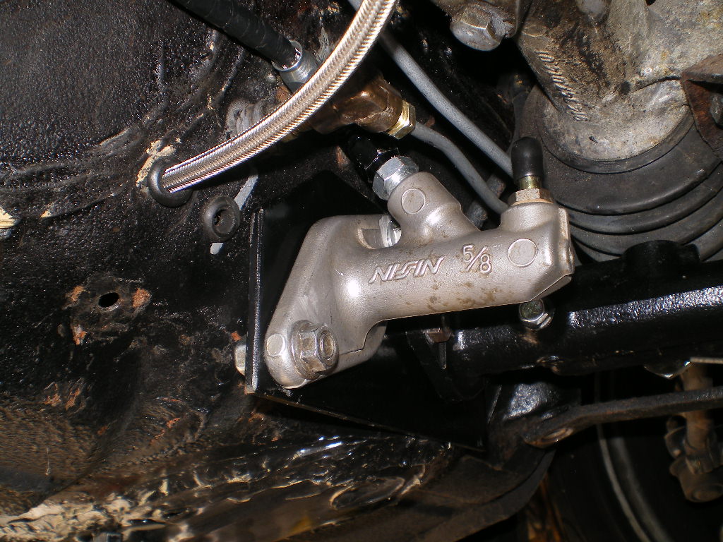
A view from inside as it sits before connecting the fork, clevis or throttle cable.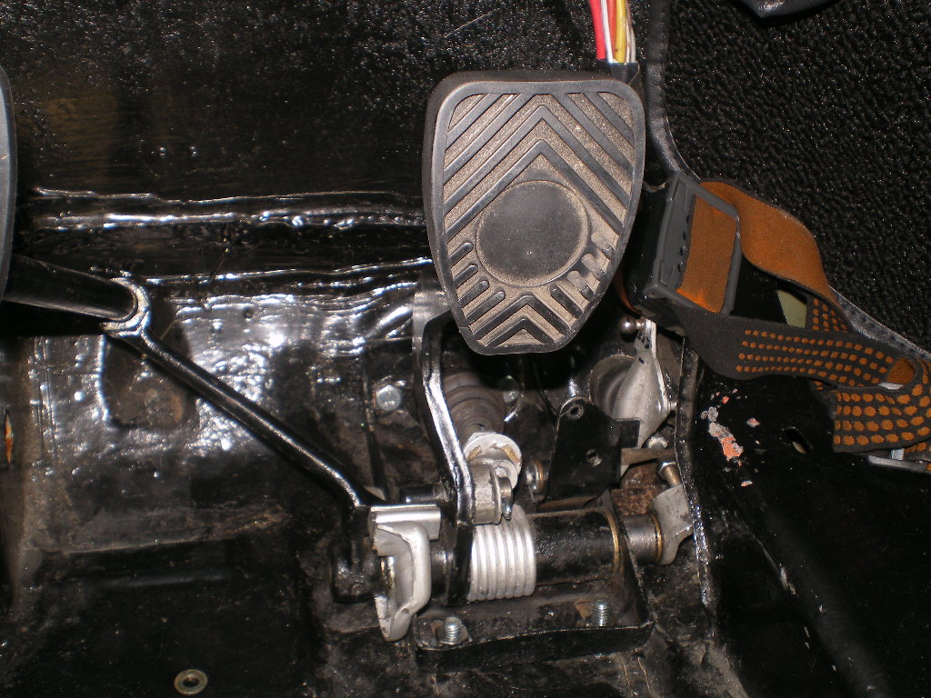
Connecting the pedal to the slave cylinder push rod. You can see the AN3 line in a couple of the pics. It is fed through the old clutch tube.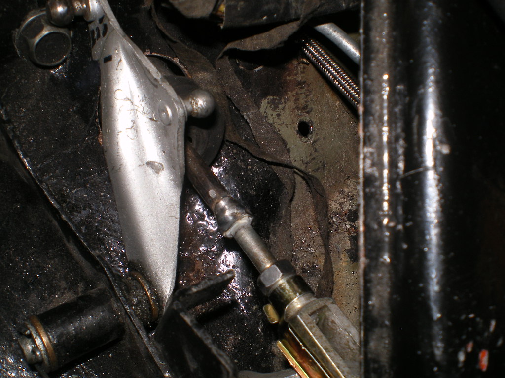
And a few with the throttle cable connected showing the clearance. It's close but they do clear one another.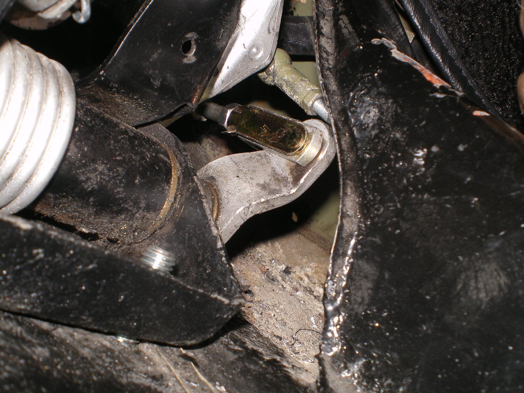
Posted by: 76-914 Sep 22 2020, 01:50 PM
And a couple of "finished product" shots. To be continued..............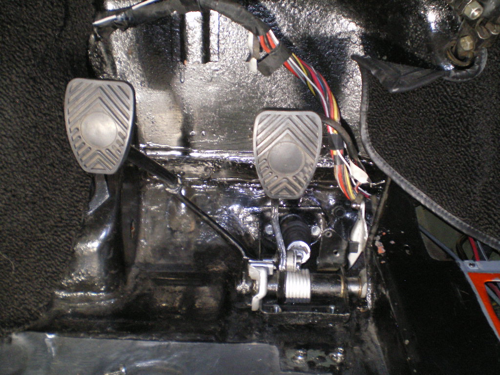
Posted by: 76-914 Sep 24 2020, 04:34 PM
Half shafts are out. After cut to length & the CV's are removed and they are ready for their trip to the machinist for a re-spline. 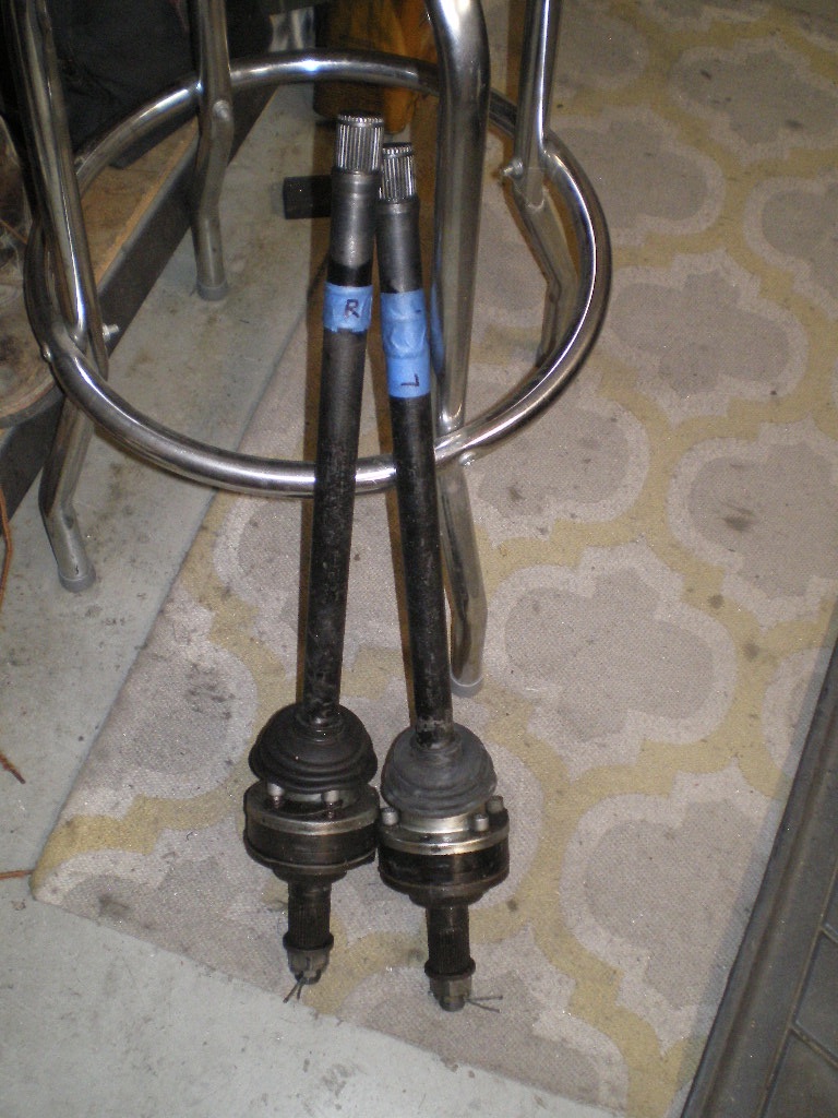
Also wired in the neutral switch, installed throttle cable sans the barrel end and the 3" silicon 90 for air intake. Outside of the harness modification, this is the "90% done and 90% to go" phase. So many things left to do after the engine and transmission are in place. Then Frank from AZ came by and picked up the transmission for his Suby conversion this morning. He is hoping for a spring launch, 2021.
Posted by: 76-914 Sep 30 2020, 01:26 PM
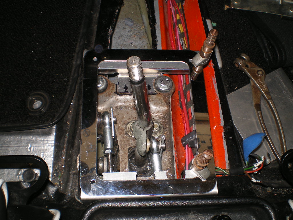
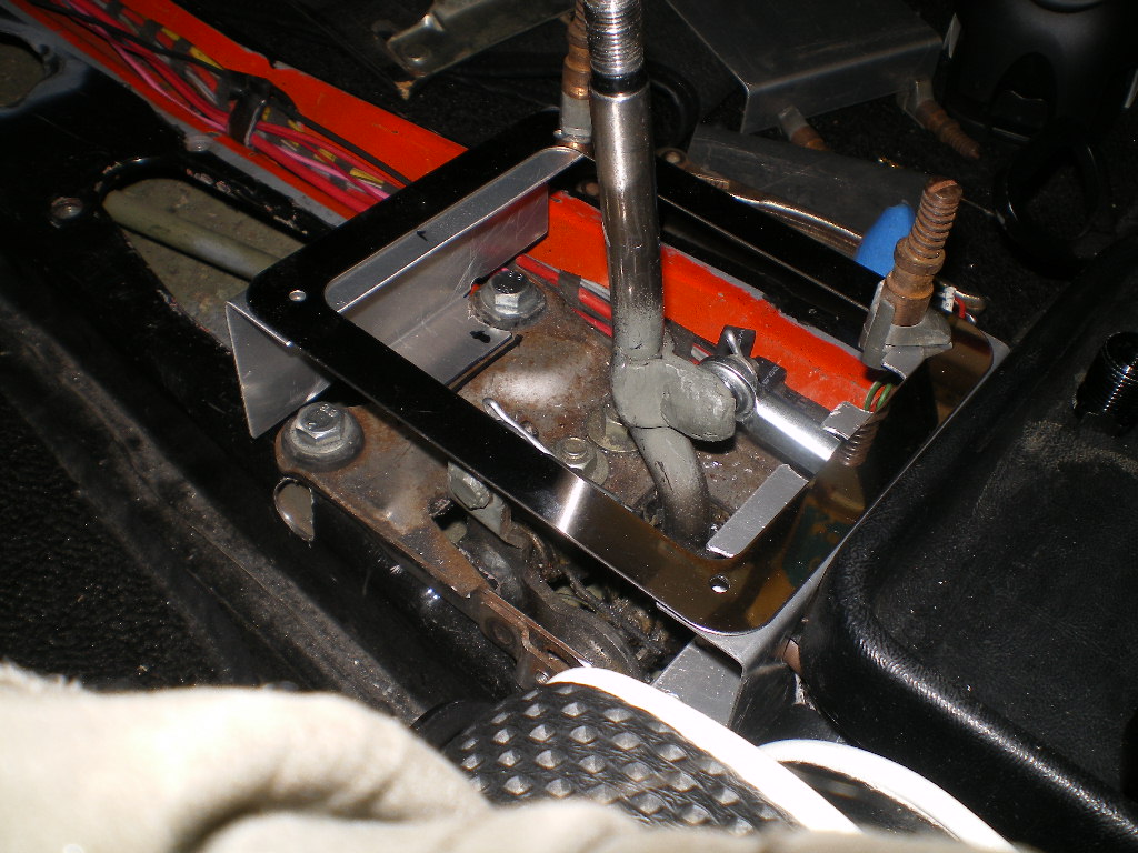
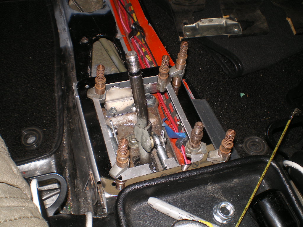
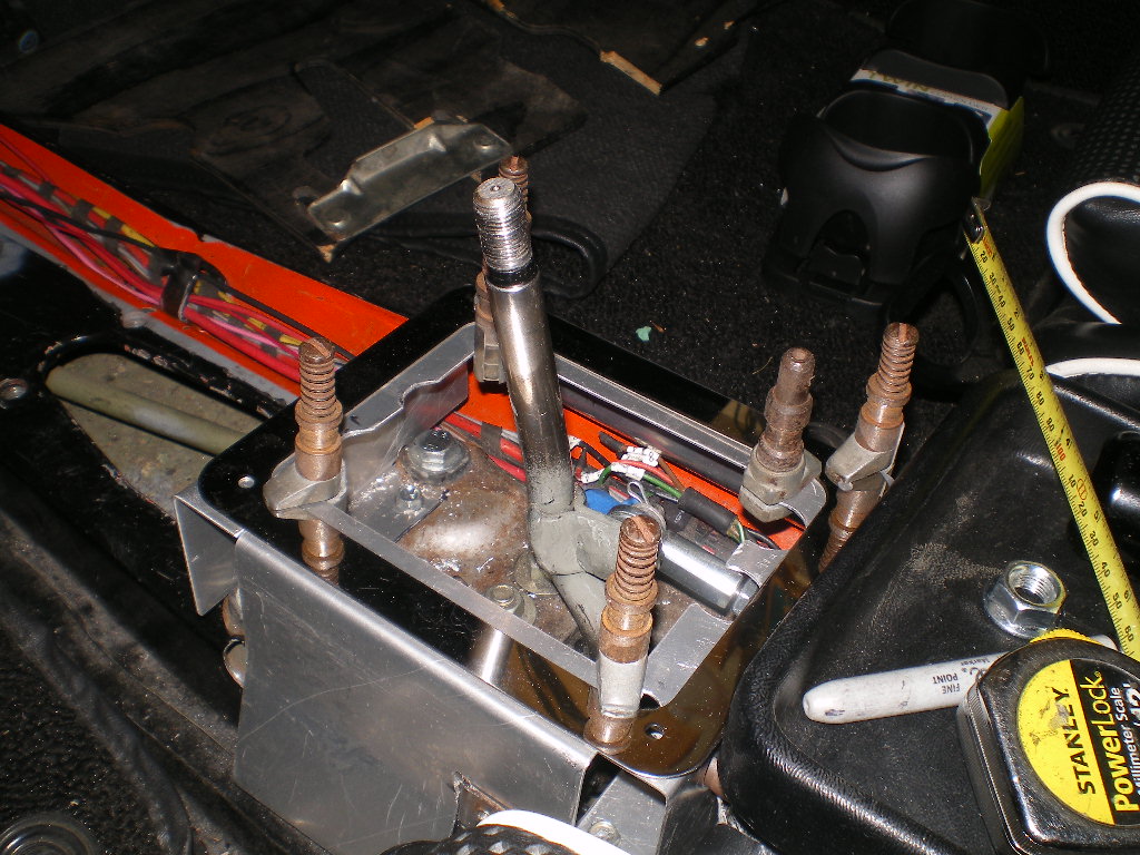
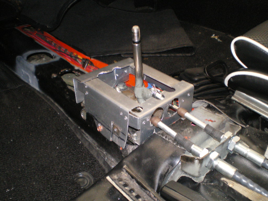
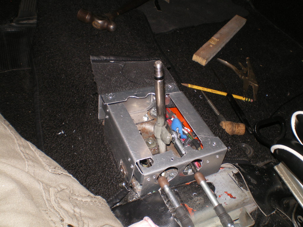
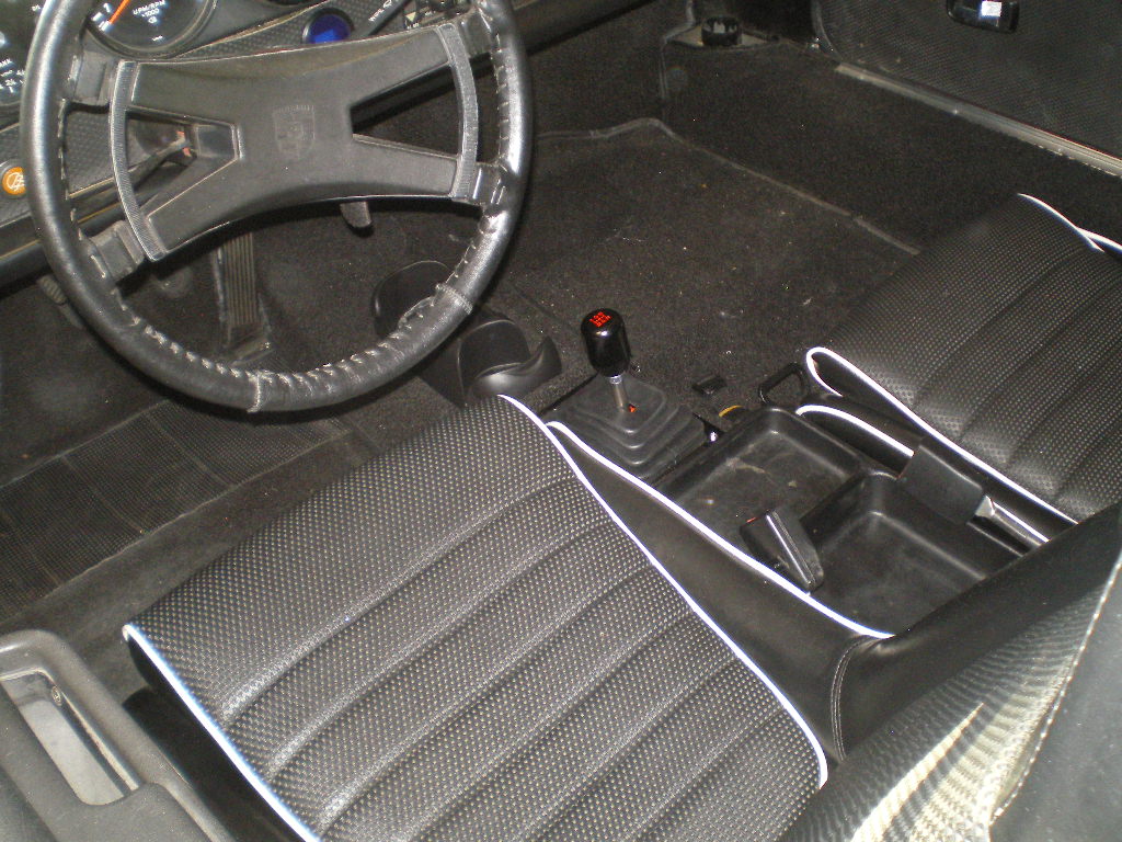
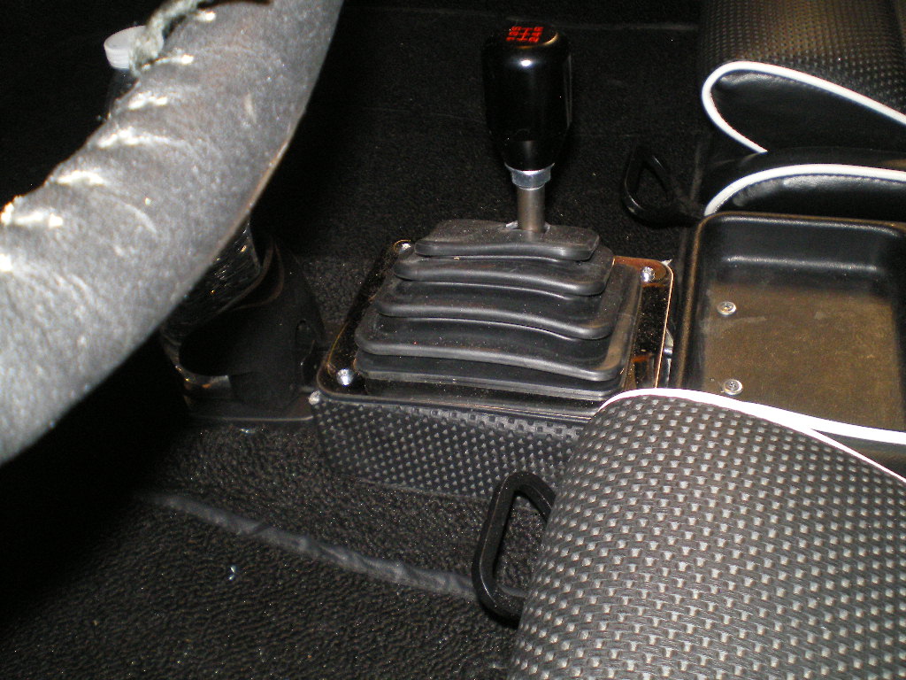
The first thing I did was remove the 4 bolts from the shifter that attaches it to the OEM base plate.
EDIT: I should mention that this setup is for cars w/o a center console. If you have a console it is not necessary to cut the tunnel. Nor will it be necessary to cut the shifter base. Simply locate the shifter rod where the old one was. Then drill 4 8mm holes and use 4 studs as stand offs to elevate the shifter base above the tunnel enough to clear it. It will be necessary to raise the deck lid of the console a couple of inches. 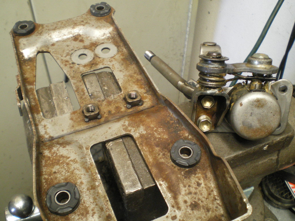
Next I marked the base plate along the line of the curvature. Cut it on the flat part before the curve begins so it is nice and flat when screwed down. I also drill out out the threads in the 2 tack welded rear plate nuts at this time.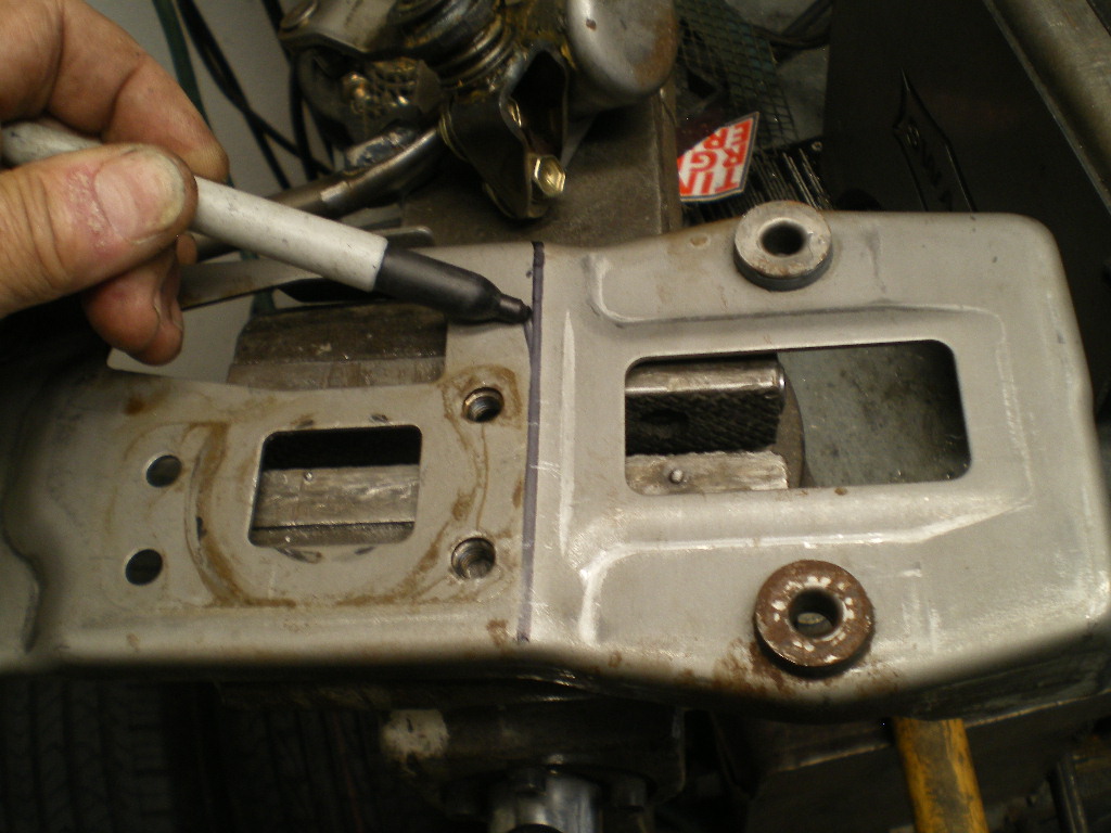
After cutting the base plate re-attach the shifter assembly to it.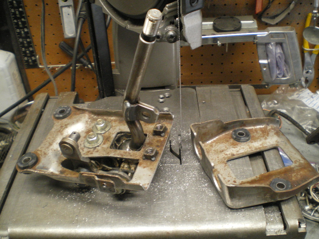
Now hold the assembly with the cut edge adjacent to the flange of the brace that spans from side to side. Then trace out the round part of the shifter base. Next drill that out with a 1.5" hole saw. You can see that the hole ends up next to the 8mm & 6mm existing holes. The hole saw actually removed the 6mm nut that was tack welded in. No matter; that wasn't to be used anyway. 
Now sit the shifter assembly back in place. With the round part of the shifter assembly centered in the hole you just cut. Mark the remaining area that needs to be trimmed. Do your best to center the base left & right as there isn't much room for the 2 front bolts. 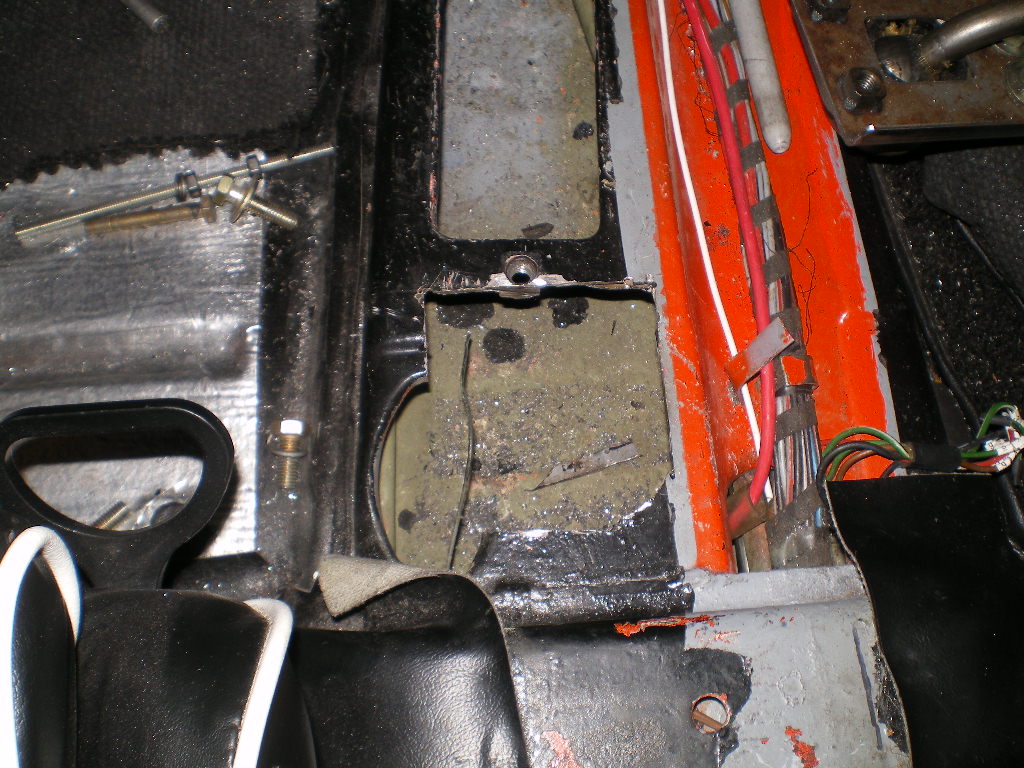
Then I checked that the shifter sat where it needed to be and that it could move through it's full range of motion. Then using the base plate as the pattern I marked the holes with a center punch. If you don't have a set of center punches you can used the holes in the base plate as a guide for your drill bit. 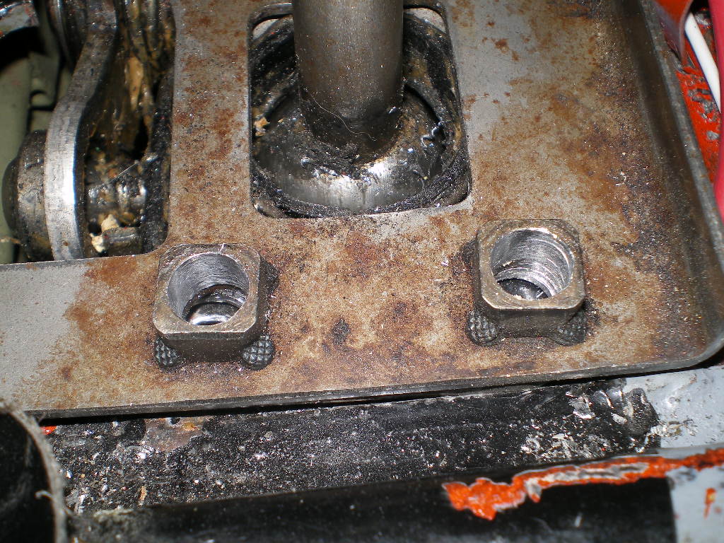
After drilling the 4 holes I placed 2 8mm bolts from inside the tunnel and used perm-a-gum to hold them in place. Then I placed the shifter assembly over the 2 8mm bolts and attached the nuts. Notice the cut on the base plate is adjacent to the flange on the crossmember.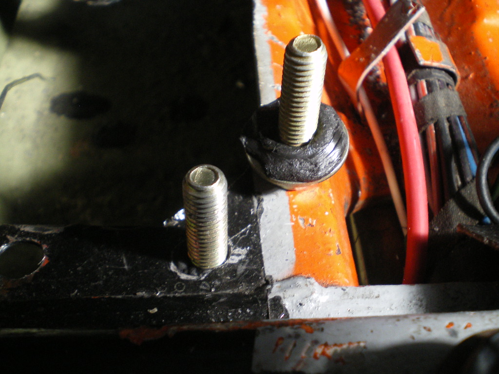
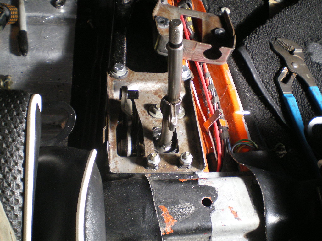
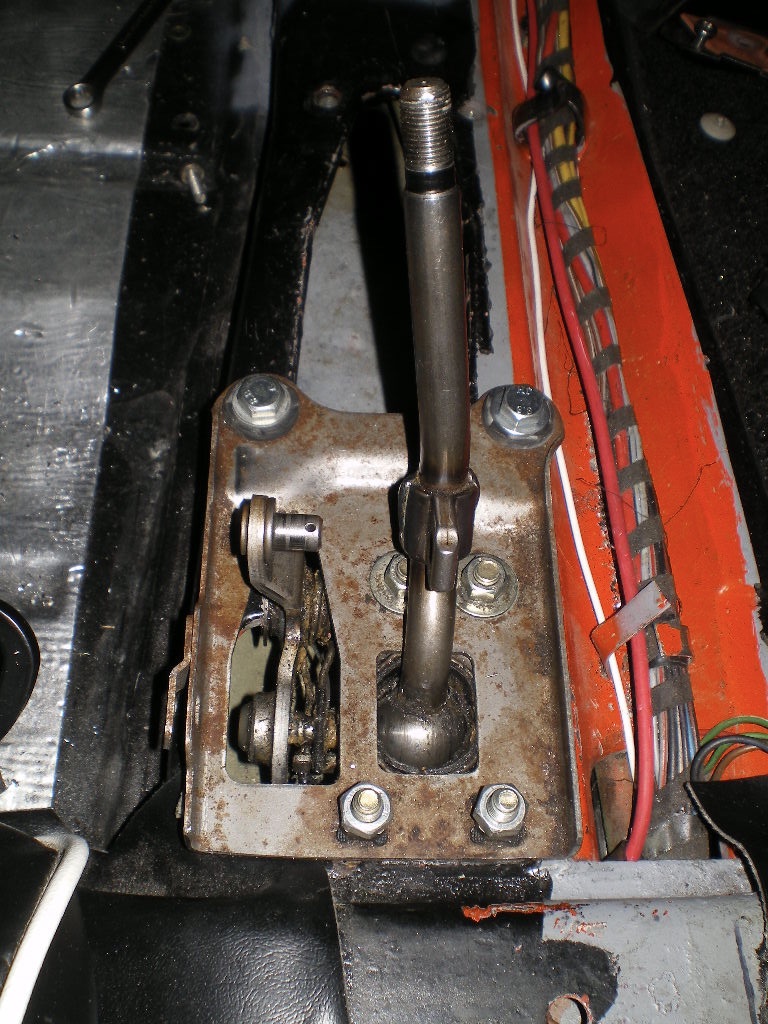
The front nuts are below the base plate and the right side nut was easy to start but the left side was so close that I had to drill a relief hole from the side of the tunnel. If I had been more careful I would have moved the assembly over 1/4"to the right. After I get the cables I will trim and install the back half of the base plate that was cut off. I will need that part for attaching the cables. To be continued...................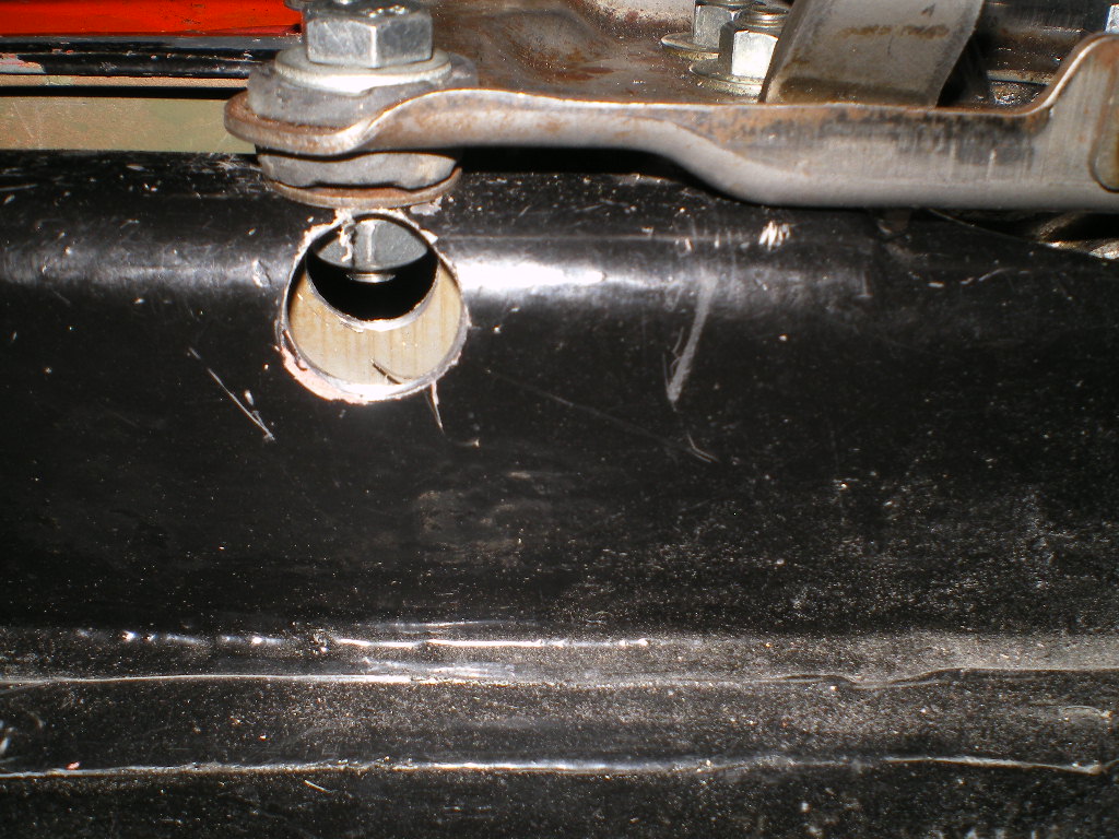
Here are a few pics of it anchored in place. 
Attached image(s)

Posted by: 914Subaru Oct 1 2020, 07:28 PM
Kent,
This new project is looking good. I was inspired by your H6 at RRC2020 and I purchased a 2003 Outback last week and I have a manual transmission to match up to it. The H6 is such a smooth running engine and I am excited to get in in something soon.
Posted by: Montreal914 Oct 1 2020, 09:24 PM
Nice shifter location.
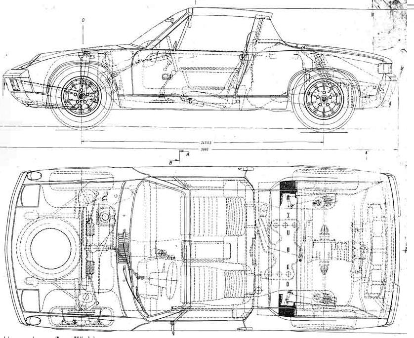
How far back from the original one is the new straight up shift level? I am looking into doing this with the stock setup. Probably upgrading to a Rennshift but with a straight up stick.
From the 904 side drawing, the shifter is before the steering center point (drawing a vertical line down).
The 914/4 or /6 in the center image, is way to the front, as we know. With the bent lever, the movement is much more of an up and down vs. front to back.
Last cross section is the 914-8 where the straight up shifter is pretty much in line (vertical) with the steering center point. The 914-8 had a completely different shifter linkage that actually went 90 degrees to the passenger side in front of the seat, then along the passenger long. 
Posted by: 76-914 Oct 2 2020, 10:20 AM
Kent,
This new project is looking good. I was inspired by your H6 at RRC2020 and I purchased a 2003 Outback last week and I have a manual transmission to match up to it. The H6 is such a smooth running engine and I am excited to get in in something soon.
Thx Ross. I was equally impressed with your's. More especially that steel roof. Seamless installation you have there. These Subaru conversions are showing up everywhere these days. Like a marriage made in Heaven, eh?
EDIT: @http://www.914world.com/bbs2/index.php?showuser=9667 Ross, I forgot to mention that Outfront Motorsports has the 3 bolt manifold exhaust flanges that you will need when fabricating your exhaust system.
Posted by: 76-914 Oct 2 2020, 10:26 AM
Nice shifter location.
How far back from the original one is the new straight up shift level? I am looking into doing this with the stock setup. Probably upgrading to a Rennshift but with a straight up stick.
From the 904 side drawing, the shifter is before the steering center point (drawing a vertical line down).
The 914/4 or /6 in the center image, is way to the front, as we know. With the bent lever, the movement is much more of an up and down vs. front to back.
Last cross section is the 914-8 where the straight up shifter is pretty much in line (vertical) with the steering center point. The 914-8 had a completely different shifter linkage that actually went 90 degrees to the passenger side in front of the seat, then along the passenger long.
I'll get you a side view pic once my axles come back from the machine shop. Presently it is on the rack and I can't open the doors enough for a good pic. Can't roll it off away w/o the flanges in the rear wheel bearings either. I'll get a few measurements in the mean time. I will say it is easily within reach where it sits.
EDIT: @http://www.914world.com/bbs2/index.php?showuser=12023 I should be able to roll it off next week as my axles are due back Friday, I hope. I did a visual and it appears that the stalk is lined up with the center of the steering wheel's vertical plane. I'll put a level to it and verify later.
Posted by: 76-914 Oct 5 2020, 06:30 PM
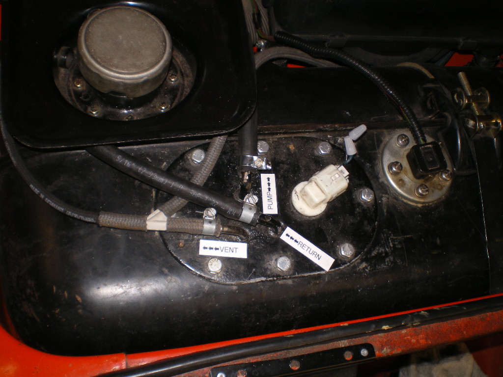
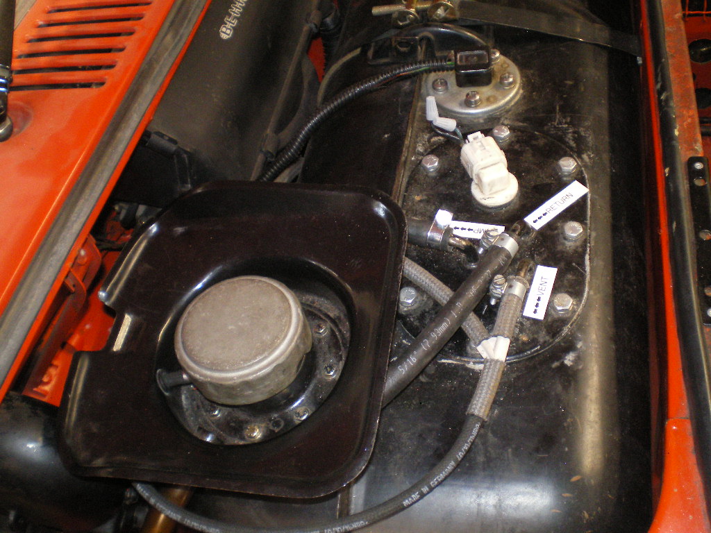
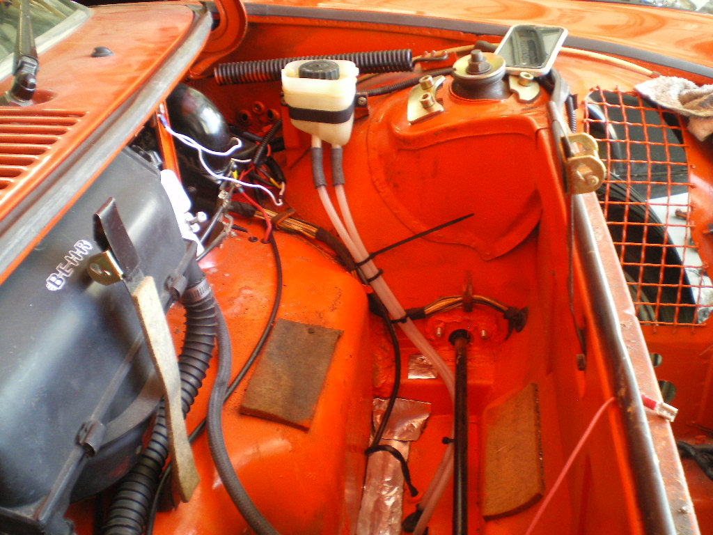
The fuel hose arrived this weekend so I was able to button that up and run the line up for the MC reservoir. That allowed me to install the gas tank. This is the tank that I originally had modified for the conversion on the '73. You might remember that I pulled it installed another with an external pump. That was done when I was chasing my tail and trying to eliminate the vapor lock problem was I was having at that time. Turned out that it had nothing to do with the Subaru submerged pump. Regardless I kept it and I'm glad that I did. One less thing to do. Beside, I really like having the hose connections on top. 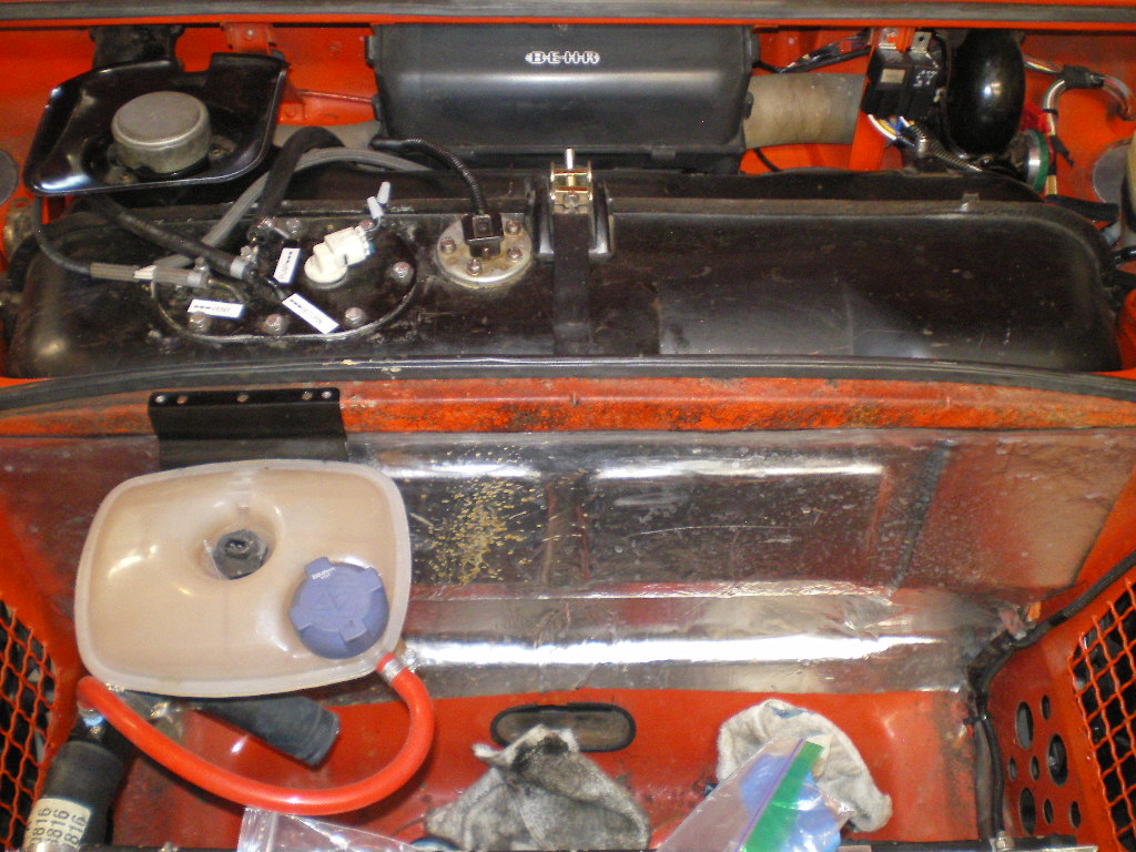
I was able to scratch the throttle cable off the list today. The cable from the V8 was still installed so I thought "What the Hell" nothing to lose. I'll try and modify it for my needs. There isn't much to it. As you can see in the first pic below it was way too long and didn't have the correct end on it either. I needed to shorten the sheath by 12" as well as the 3/16 inner steel cable.

I attached a 5/16 FI style clamp adjacent to the cut. The innermost part of the sheathing has a 3/32" plastic tube. Around that is a SS flat wound wire and finally the black plastic outer layer. I used a Dremel blade to cut the cable. I cut it from the end that mates to the firewall since these are usually falling apart at this junction. Just my luck this on wasn't.  I was able to remove the 12" section by placing the small end in the vise and clamping down slightly on the edges of each clamp mark.i.e. the clamp they used in the factory is octagon shaped. By pressing slightly on the crown of each corner helps to round out the end al little bit. Then pulling the cable while rotating it clockwise. it slowly backed out. To get the sleeved end back to round I placed a 17/64" drill bit with the bald end up in the vise. Then hammered the sleeve back over it. It only went in about 14". I looked inside the sleeve and noticed these tiny dimples that are there to help grip the sleeve. So I used a 1/4" bit to flatten the dimples some what then followed up with the 17/64" to round it out. Now I was able to thread the cable sheath back onto the sleeve by pushing while turning counter clockwise. It worked like a champ. I won't trim the steel cable until I have the pedal board and gas peddle back in place but that will only take a minute. I'm happy with the way it turned out but in all honesty the only reason I tried this was I had nothing to lose and everything to gain. Start to finish was less than 30 minutes. Sorry about the order of the pics. Something about this site isn't friendly about posting and editing pics with this Mac. Hoping for some upgrades here now that we are supporting it $$$ wise.
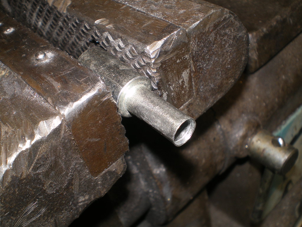
Attached image(s)
Posted by: Montreal914 Oct 5 2020, 08:34 PM
Thank you for the added shifter information. Looking forward seeing it on a side view,
Posted by: Gint Oct 5 2020, 10:05 PM
Excellent work Kent! Subscribed
@http://www.914world.com/bbs2/index.php?showuser=9964
I did, however, purchase a HF welding cart and some supplies, but misplaced my helmet somewhere along the line
Mark, long time man. You're supposed to use your new welder to make your own cart.
 @http://www.914world.com/bbs2/index.php?showuser=7300
 Kent,
This new project is looking good. I was inspired by your H6 at RRC2020 and I purchased a 2003 Outback last week and I have a manual transmission to match up to it. The H6 is such a smooth running engine and I am excited to get in in something soon.
Thx Ross. I was equally impressed with your's. More especially that steel roof. Seamless installation you have there. These Subaru conversions are showing up everywhere these days. Like a marriage made in Heaven, eh?
EDIT: @http://www.914world.com/bbs2/index.php?showuser=9667 Ross, I forgot to mention that Outfront Motorsports has the 3 bolt manifold exhaust flanges that you will need when fabricating your exhaust system.
As was I Ross. Your roof looks fantastic.
@http://www.914world.com/bbs2/index.php?showuser=9667
Posted by: euro911 Oct 5 2020, 11:31 PM
Hey, Mike ( @http://www.914world.com/bbs2/index.php?showuser=20 ). Yes it has been a long time. It happens when there's too much on one's plate ... especially when there's more than one plate to deal with
Hope you & Sharon are doing well? ... and maybe, some day, we'll all get to have a beer in some God-forsaken parking lot again somewhere

Posted by: Gint Oct 6 2020, 04:40 PM
Hey, Mike ( @http://www.914world.com/bbs2/index.php?showuser=20 ). Yes it has been a long time. It happens when there's too much on one's plate ... especially when there's more than one plate to deal with
Hope you & Sharon are doing well? ... and maybe, some day, we'll all get to have a beer in some God-forsaken parking lot again somewhere
Still kicking over here.
It's inevitable!
Posted by: 76-914 Oct 24 2020, 05:05 PM
Future
Posted by: 76-914 Oct 26 2020, 09:23 PM
I thought I should post this for any of you guys that need to cut down your 1/2 shafts for re-fitting to the Subaru TY75 series 5MT. This applies only to the transmissions with the male output stub. . This method of measurement is for applications where the centers of the transmission stub and wheel bearing are lined up vertically & horizontally. If your application is not centered a simple right angle trig calc will give you the exact difference but it ain't going to amount to squat unless you have >3" variance. I do not recommend a common tape measurer for this job. I used a std 6' rule since it won't flex and has the sliding brass rule for inside measurements. Look at the 1st pic below and you will see I use the bearing to measure from. Notice I'm not measuring against the red rubber seal either. I was going to use the edge of the circular part of the drop arm but I found a difference between my '73 and this '70 model. The one pictured is my '70 but my '73 has a raised edge. I figure the metal side of the bearing is the only constant so this is what I measured off.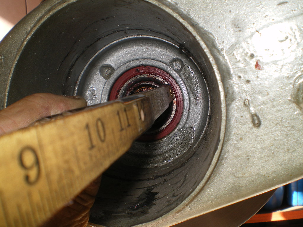
Now measure the exact distance to the end of the output stub. You can see why I like this "old school" 6' rule in this pic. 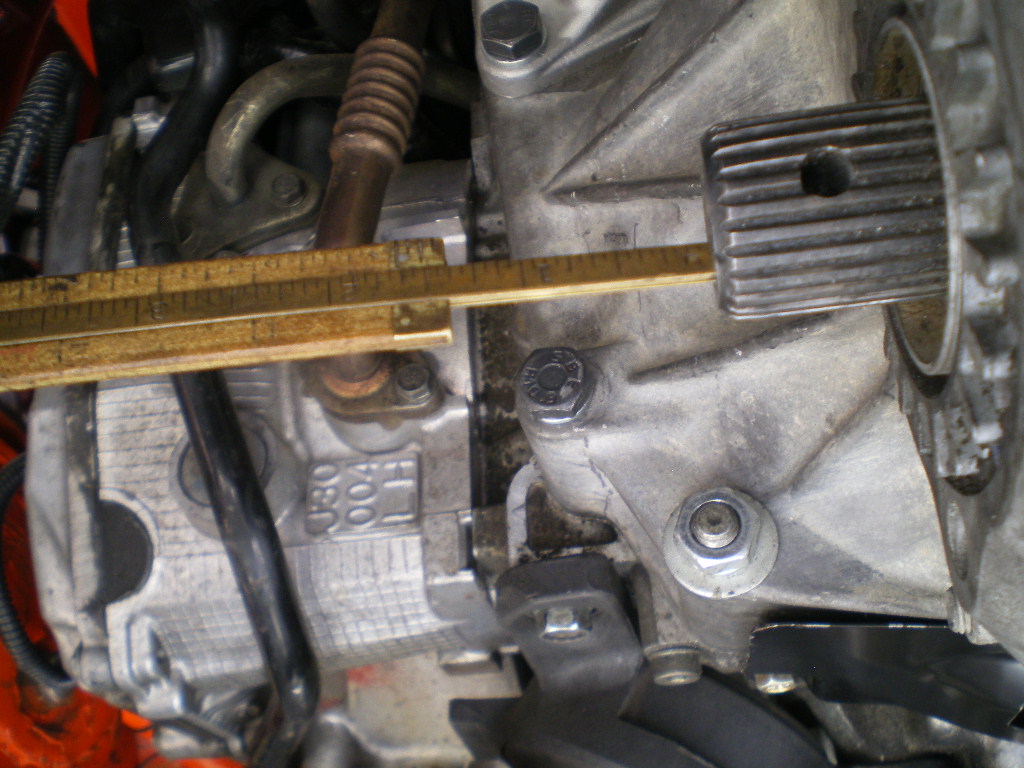
Once you have this measurement subtract 1/8" for fitting clearance and then subtract another 2 3/8". Or more simply stated where X = distance between bearing and stub;
X - 2.5" = desired length of half shaft. You can see resulting clearance when installing the assembled half shaft in the pic below. About 1/8" and this is with both CV's compressed in as far as they will go. Once assembled you should be able to slide the 1/2 shaft ~1" side to side.
****NOTE**** Don't assume both side are equal. Measure both sides. Ask me how I know. I made this mistake 6 years ago.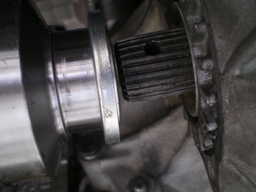
I've used Dutchman Motor Sports for both cars and their price has only increased $5 in the past 6 years. Contact there is Travis. They will need the male stub off of a Subaru 1/2 shaft, the female Spyder or broach off your Subaru CV and your cut to length 914 half shafts. And a payment of ~$175.00.
Dutchman Motor Sports
1250 E. Piper Ct.
Meridian, ID 83642
(503) 257-6604
And a few more pics just to take up space. To be continued.................
Posted by: 76-914 Oct 29 2020, 04:27 PM
Nice shifter location.
How far back from the original one is the new straight up shift level? I am looking into doing this with the stock setup. Probably upgrading to a Rennshift but with a straight up stick.
From the 904 side drawing, the shifter is before the steering center point (drawing a vertical line down).
The 914/4 or /6 in the center image, is way to the front, as we know. With the bent lever, the movement is much more of an up and down vs. front to back.
Last cross section is the 914-8 where the straight up shifter is pretty much in line (vertical) with the steering center point. The 914-8 had a completely different shifter linkage that actually went 90 degrees to the passenger side in front of the seat, then along the passenger long.
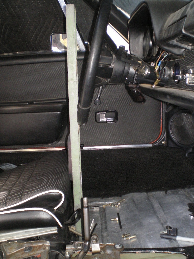
@http://www.914world.com/bbs2/index.php?showuser=12023 Got the 1/2 shafts back in so I could roll it out. Here are the pics you requested showing the shifter in relation to the steering wheel. Some pics have the straight edge , which was level vertically, against the wheel and some against the horn pad.
Posted by: Montreal914 Oct 29 2020, 08:47 PM
Thank you
That is very similar to the 914-8 cross section, pretty much in line with the lower part of the steering. Very nice!
Posted by: 76-914 Nov 9 2020, 06:04 PM
It's been a few weeks and only a few items remain. One of those items are the shifter cables which should arrive by the end of this week. I haven't even thought about how I will cover the shifter in this car. The other one was easy as I could hide everything between the console and middle cushion. But moving ahead I use some wire rope to visualize the route the cables will run because it is somewhat similar to the cables stiffness and will prevent me from making too small of a radius. I clamp the cables to the shifter on one end and to the transmission on the other. Nothing magic here but it does help to see where they will run. 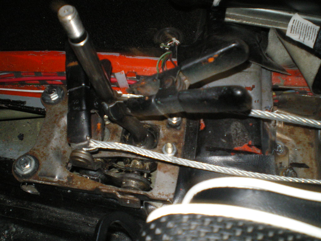
They will lay on top of the tunnel then drop thru the rear tunnel access cover and out the same hole in the firewall that the old shift rod passed through.
And from the engine compartment side.
And finally to the transmission.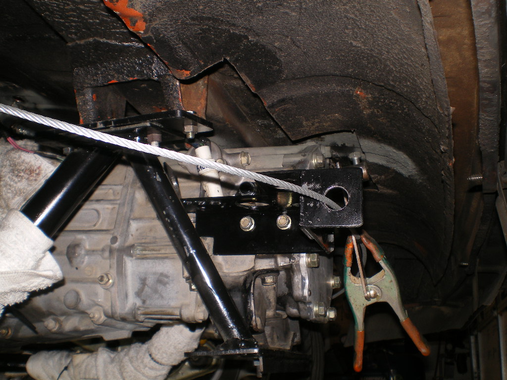
I cut the cover to allow the cables to enter the tunnel.
Then make a couple of small templates for the gussets.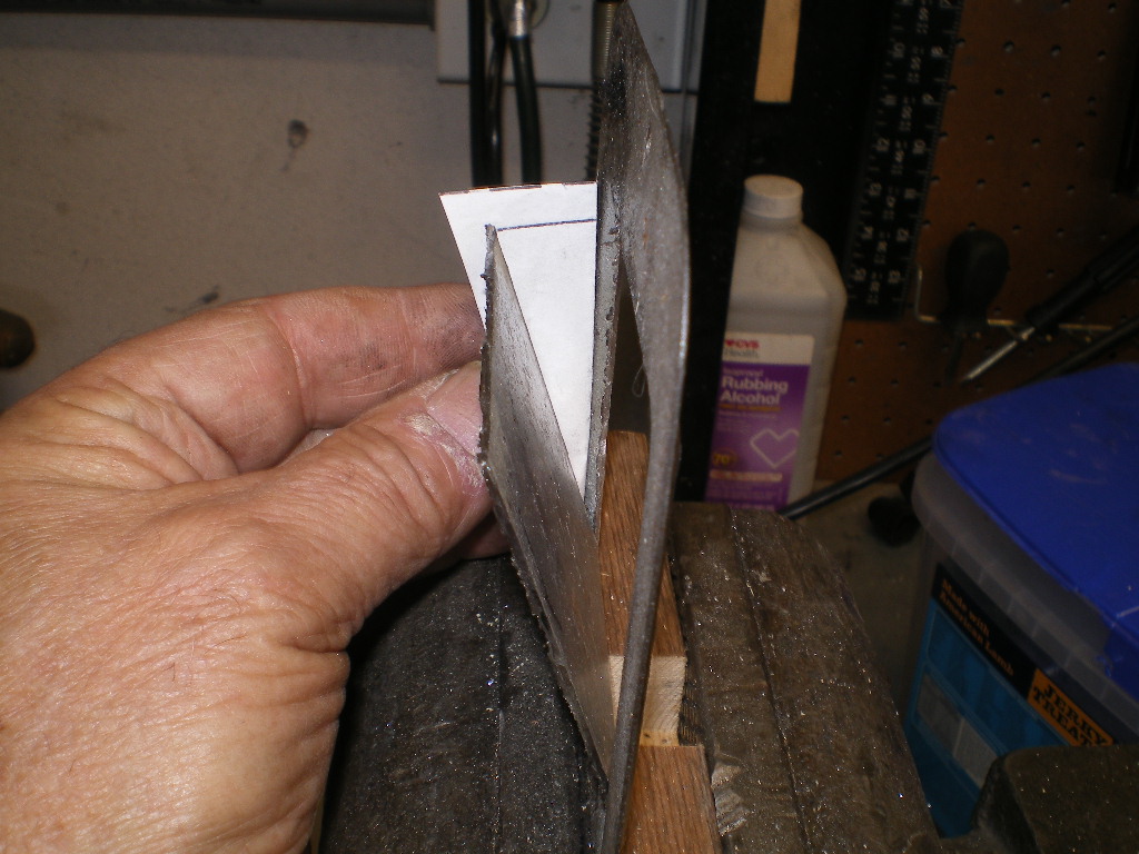
And form the gussets 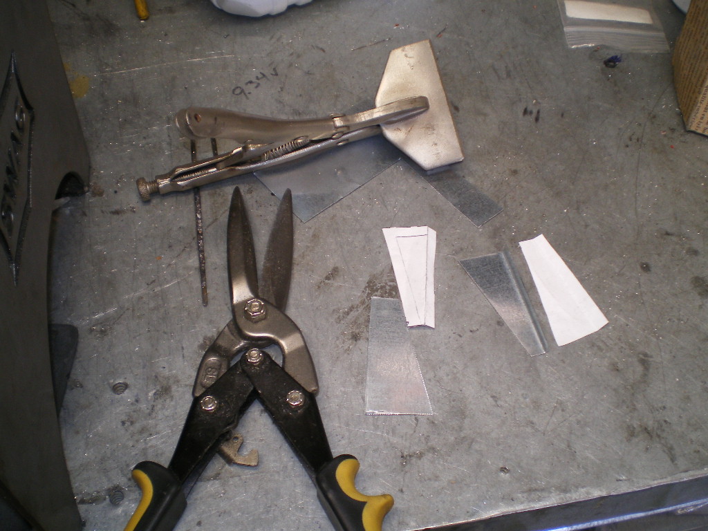
Posted by: 76-914 Nov 9 2020, 06:09 PM
Then clamp together and weld. I use this term weld loosely as I blew a hole in the thin metal and had a couple more spots bulge out on the other side of the weld. I threw some primer on it for now and will hammer down those bulges later.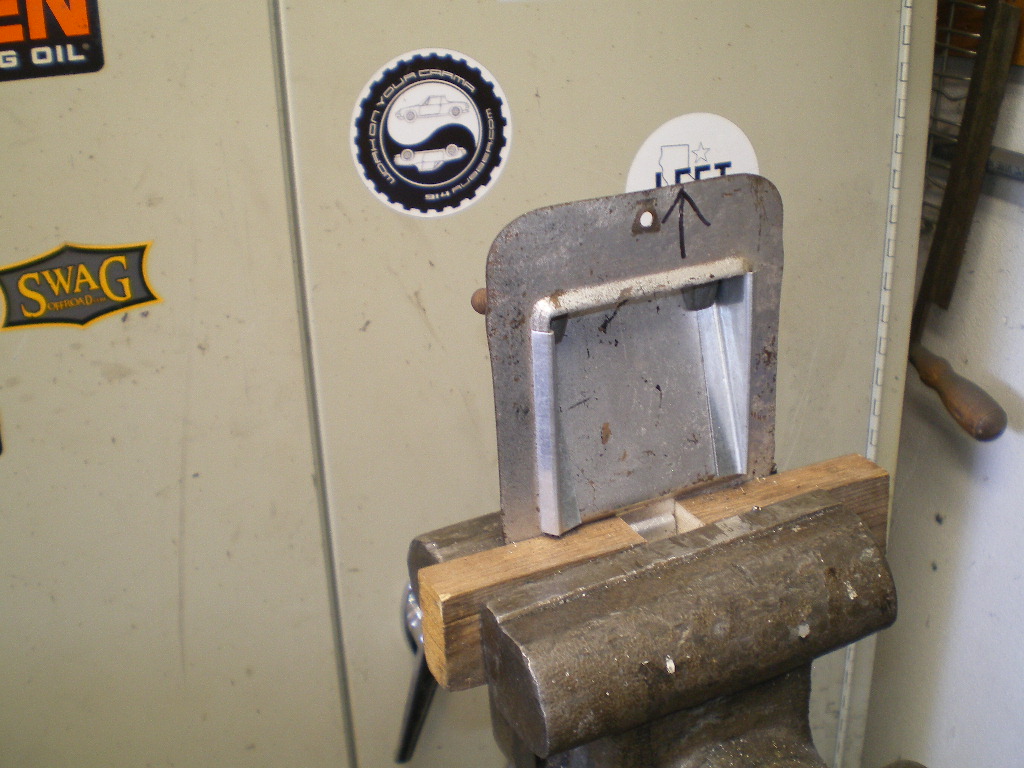
Posted by: 76-914 Nov 9 2020, 06:25 PM
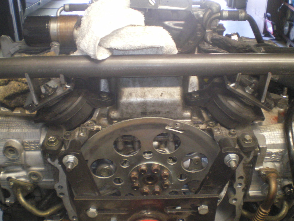
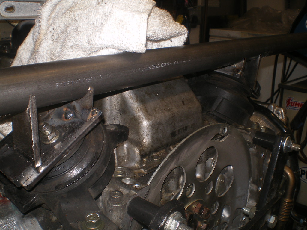
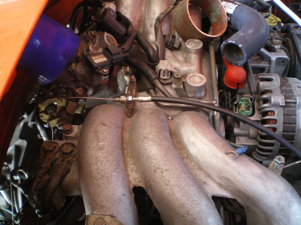
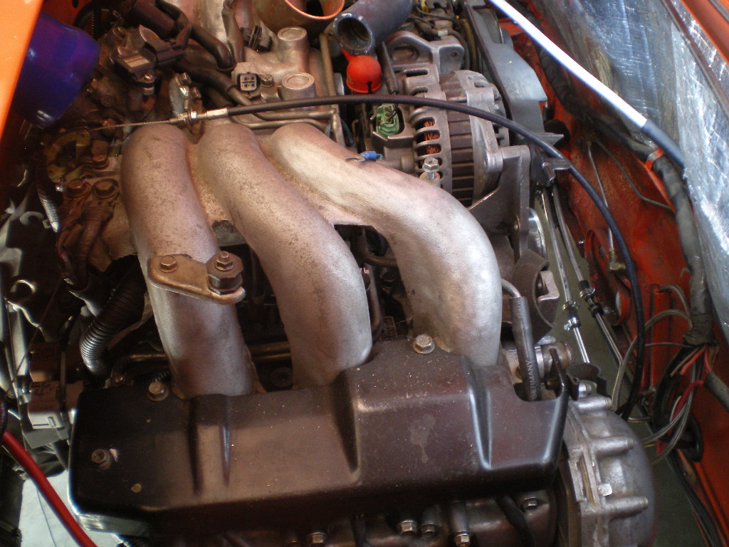
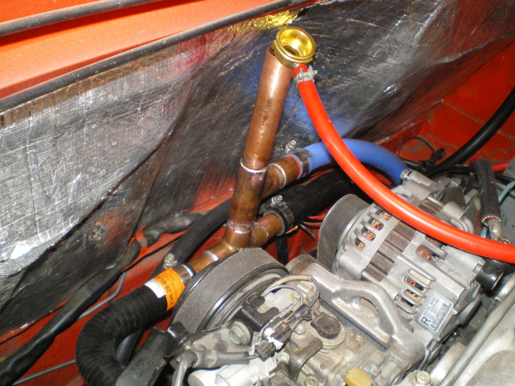
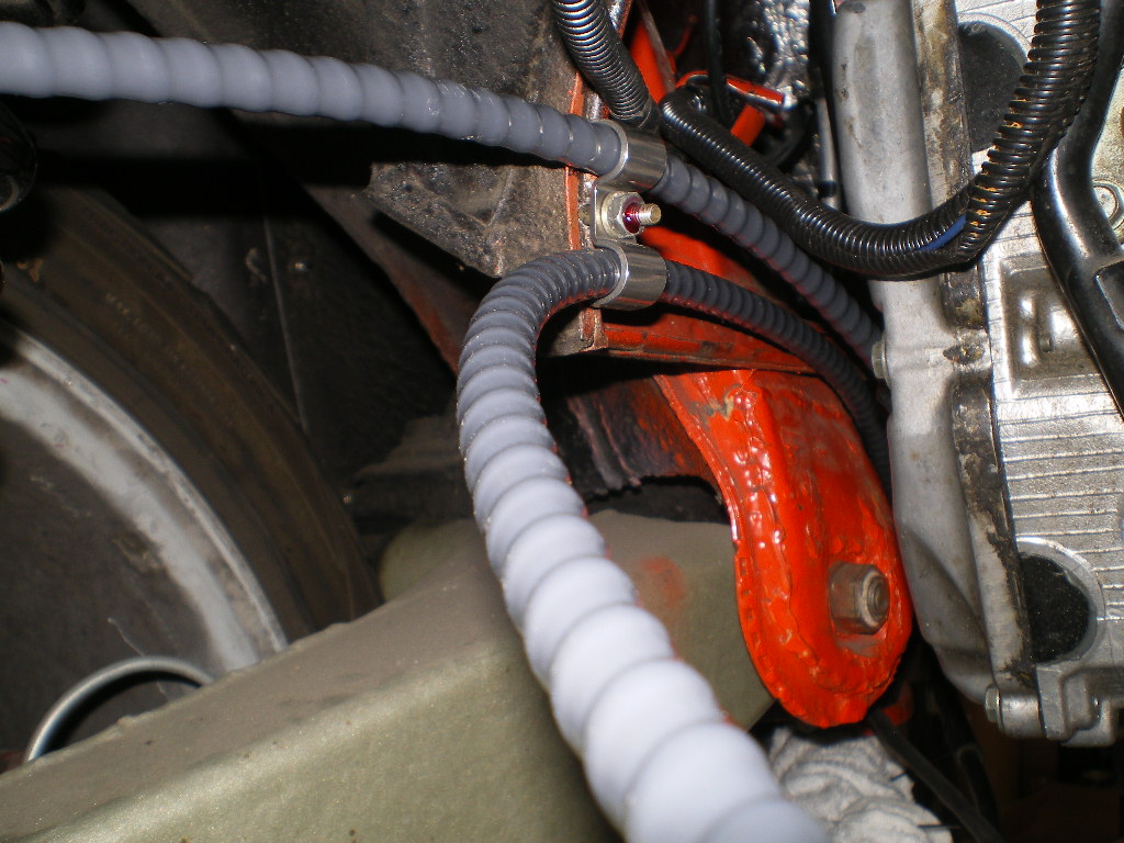
All of the plumbing is completed and tied in with the exception of the radiator filler neck. The one you see on the end of the red silicone hose is just too flimsy so I ordered another that is more substantial. It should be here in 2 weeks. I left all of the hoses a bit long for now. After I've got a few hours on the car I'll cut them to final length. 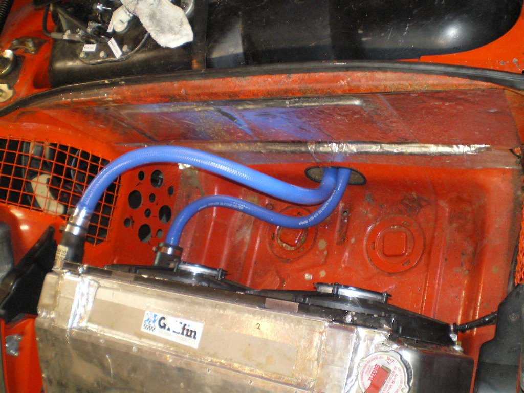
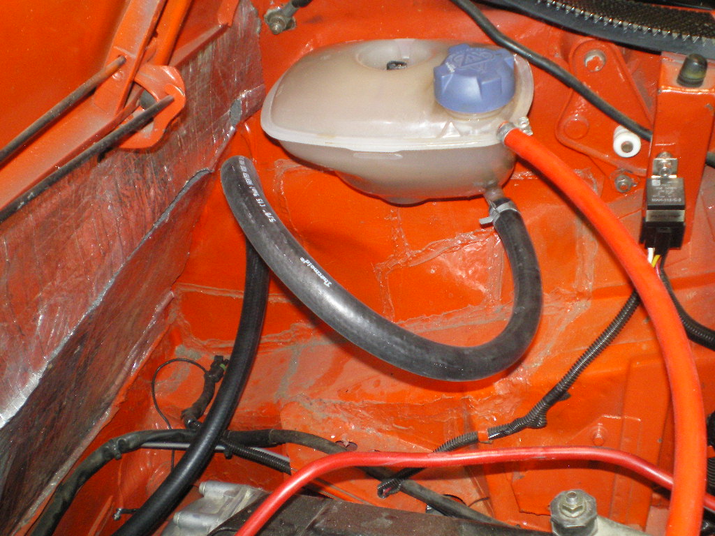
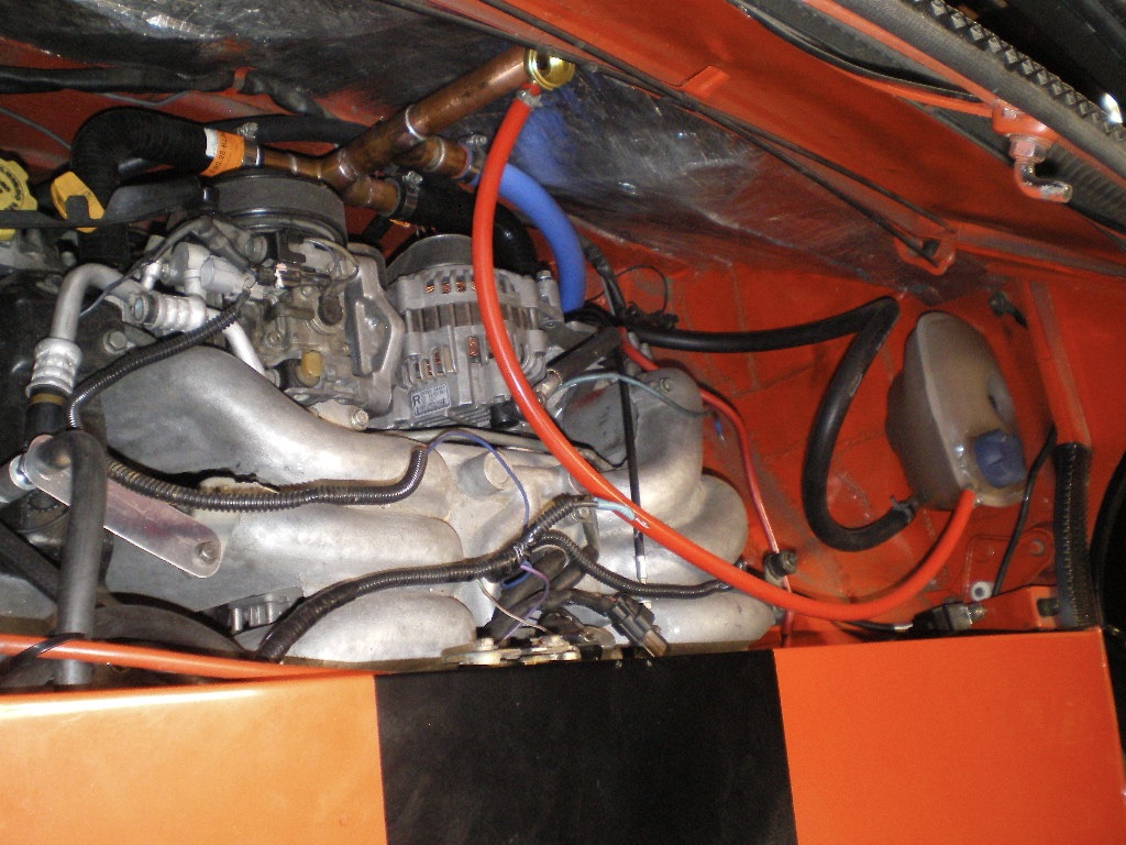
The clutch is bled and the reservoir is topped off.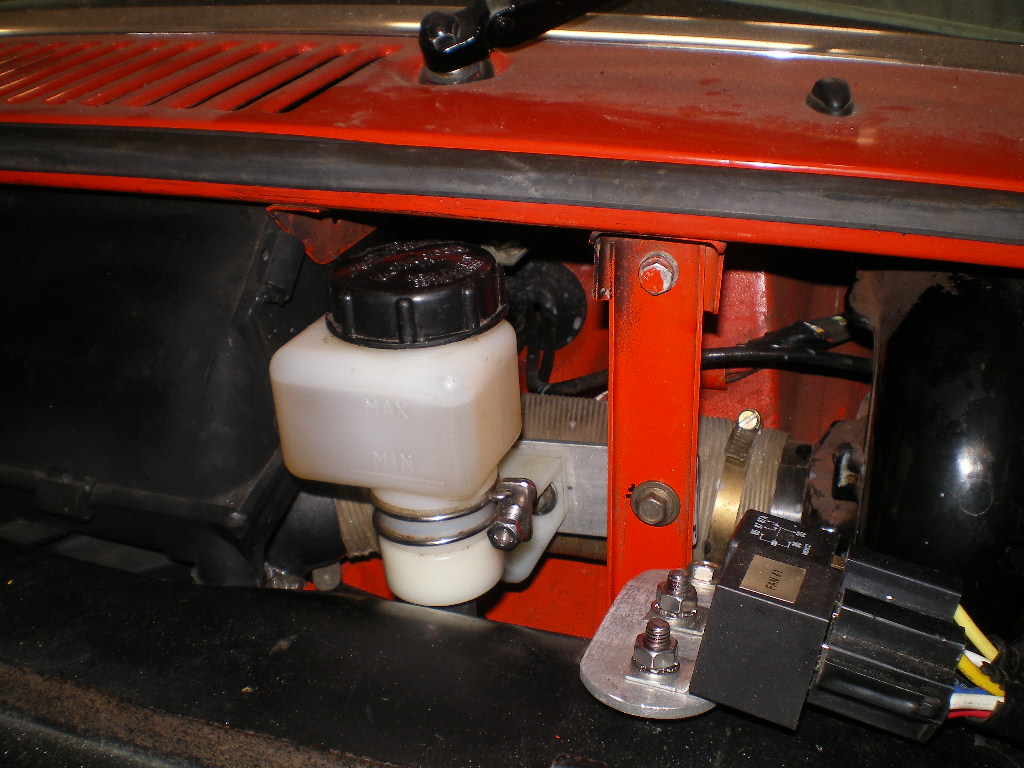
And the speedometer should be here in two weeks.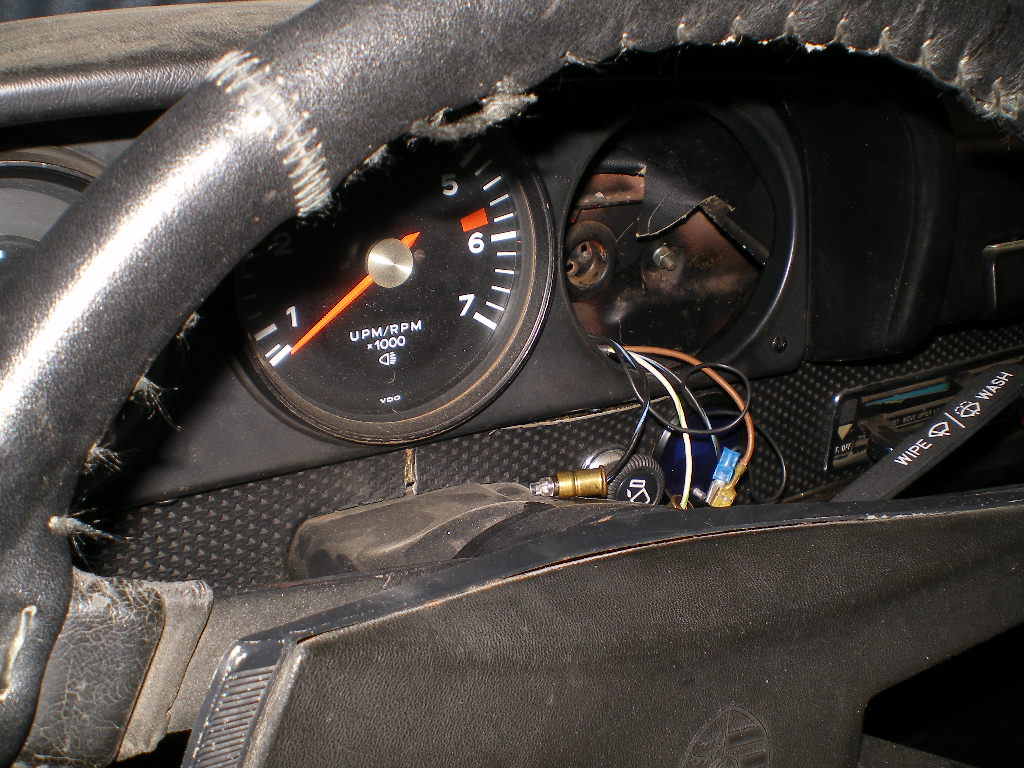
I can see the light at the end of the tunnel. God willing and the creeks don't rise this thing will be on the road by Christmas. To be continued..................
Posted by: FL 000 Nov 9 2020, 06:56 PM
No idea how I have missed this thread until now. Nice job documenting it, I am sure it will help me as I embark on my trans swap soon.
Posted by: 914GTSTI Dec 1 2020, 10:11 PM
Thanks for all the great Ideas ! Your the MAN !
Posted by: Chris H. Dec 1 2020, 10:33 PM
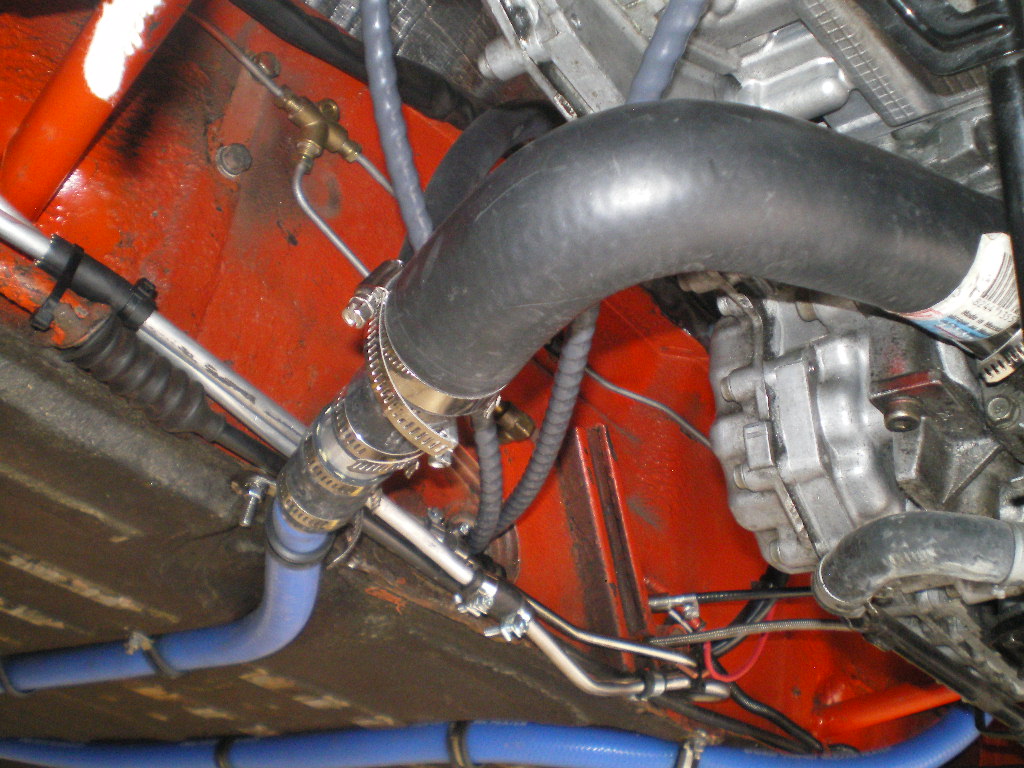
Looks great Kent! What size radiator hoses did you use? 3/4 and 7/8? I’m actually thinking about going back to smaller diameter myself.
Posted by: 76-914 Dec 2 2020, 04:50 AM
Looks great Kent! What size radiator hoses did you use? 3/4 and 7/8? I’m actually thinking about going back to smaller diameter myself.
Yes, 7/8" & 3/4". LMK if you do. I'll send you some nice blue silicon hose that I have left over, Chris . I forget which but I think it is 3/4" that I have surplus stock.
Posted by: Chris H. Dec 2 2020, 01:16 PM
Looks great Kent! What size radiator hoses did you use? 3/4 and 7/8? I’m actually thinking about going back to smaller diameter myself.
Yes, 7/8" & 3/4". LMK if you do. I'll send you some nice blue silicon hose that I have left over, Chris . I forget which but I think it is 3/4" that I have surplus stock.
Oh nice, will do Kent!
Posted by: 76-914 Dec 11 2020, 11:56 AM
I have some catching up to do here. I received my cables from CCI and they are top notch as usual. In case you're wondering they are 90" & 98" long. Here are a few pic's of them and of the installation. 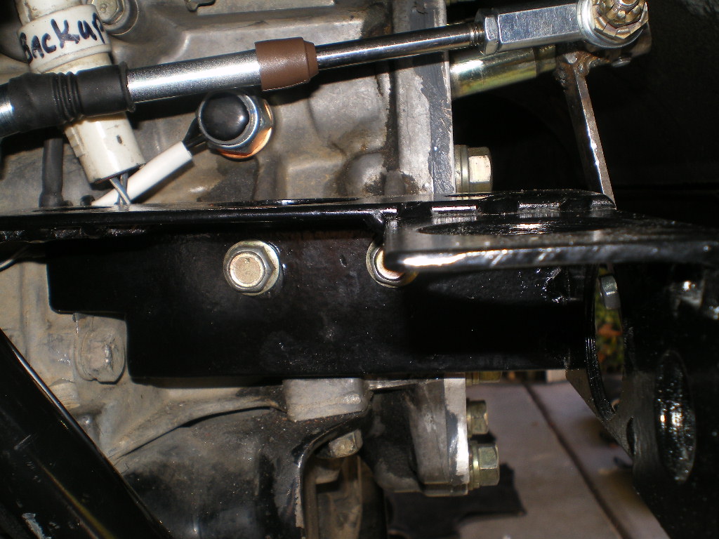
This lever was made using a scrap piece 1/2" steel pipe, 1/8" plate steel and an AN-3 bolt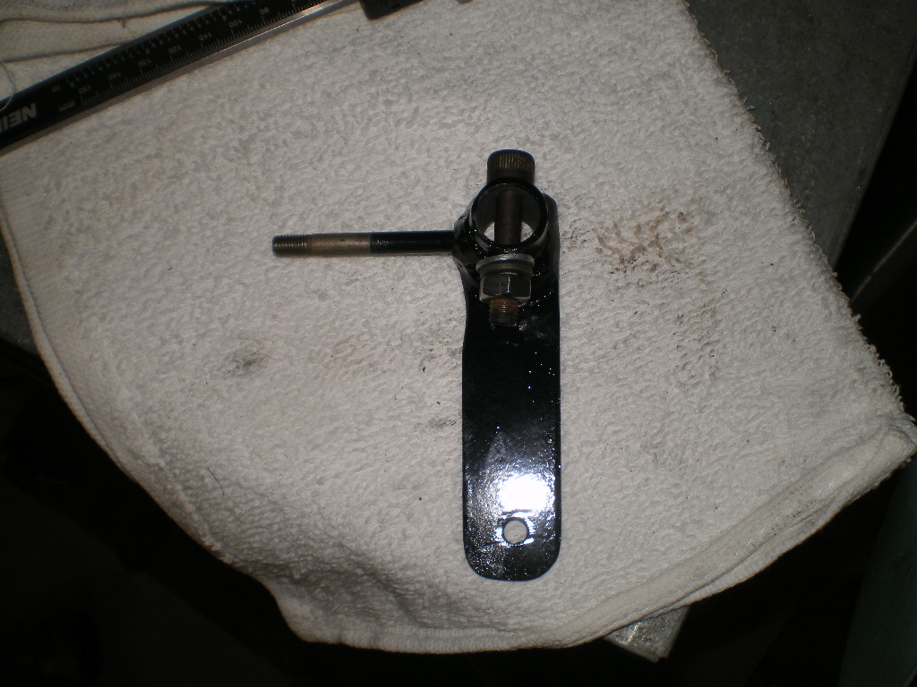
A few shots from inside the cabin.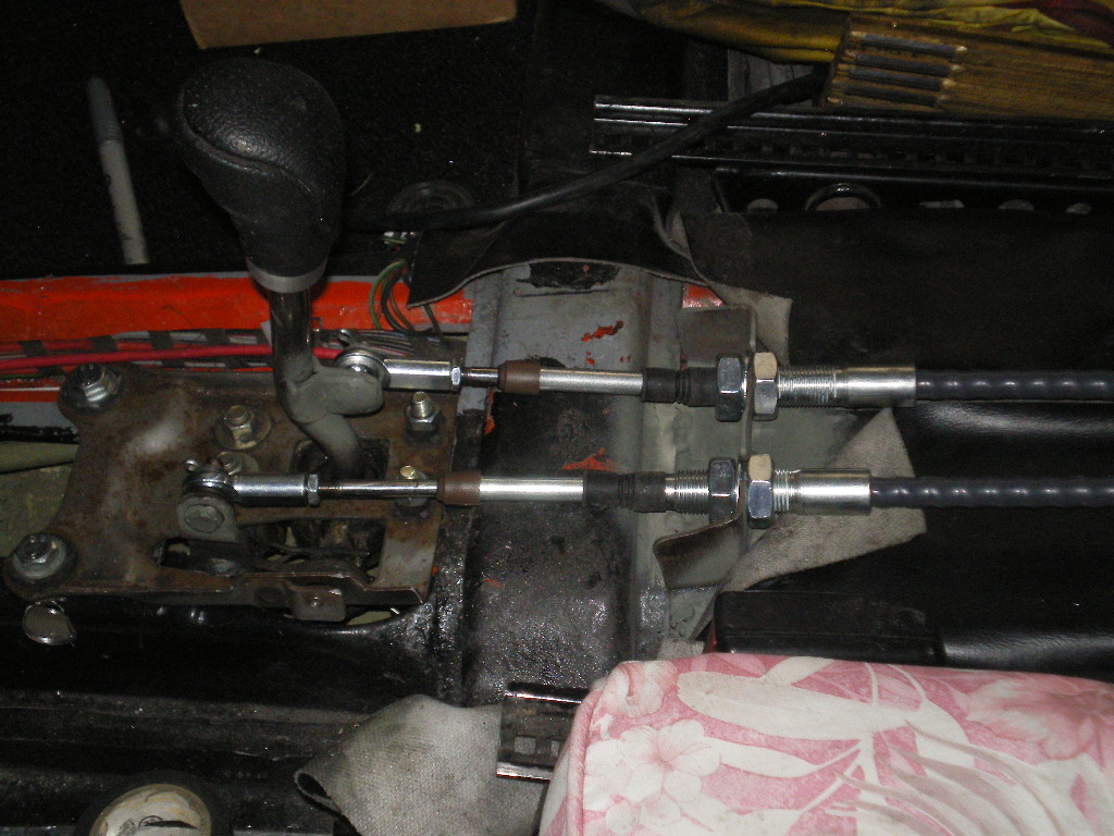
Posted by: rhodyguy Dec 11 2020, 12:08 PM
Party ON!
Posted by: Mueller Dec 11 2020, 02:12 PM
Nice job, might have to borrow a few of your design ideas when I put my Subaru gearbox in.
Posted by: 76-914 Dec 25 2020, 05:09 PM
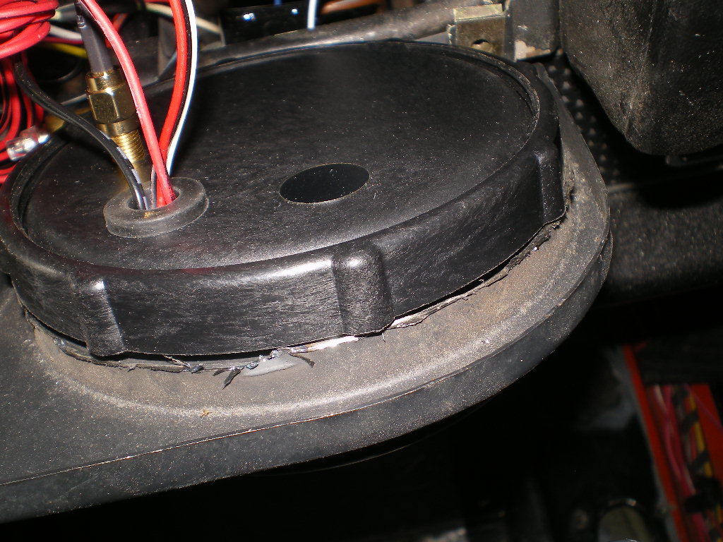
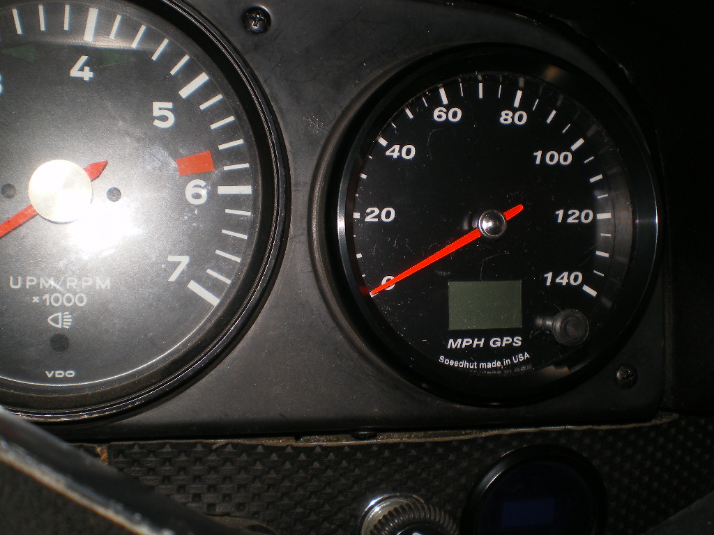
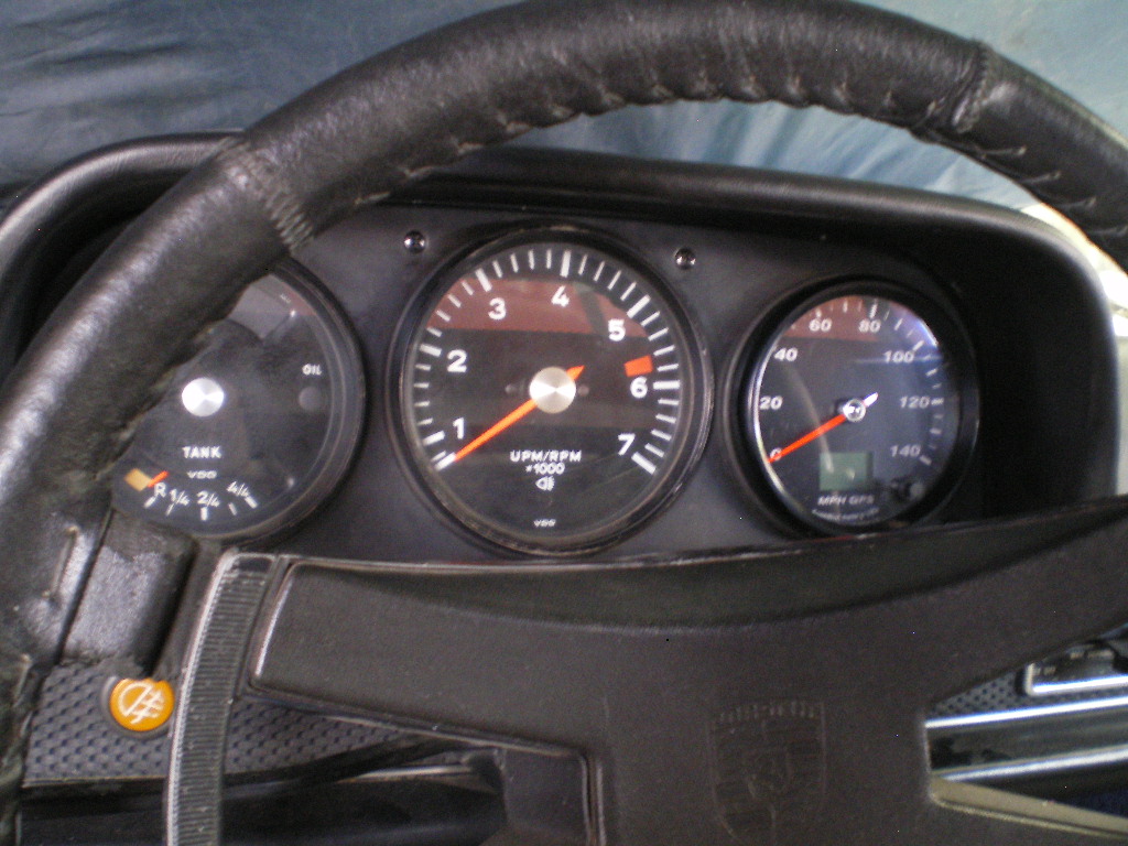
Thx Mike. Well, I went to way much trouble installing one of these Speed Hut Speedometers a few years back when I converted the black 914. I made another gauge panel to accept the gauge but there is an easier way. The problem is that the plastic mounting nut will not screw onto the body of the gauge because the threads on the body of the gauge are partially covered by the shoulder/flange of the OEM opening. So you will need to remove the 4 small metal pieces (with a Dremel) to shorten the shoulder that the gauge body sits in. There are 4 of these "tabs". You can see 3 of them sitting on my leg after cutting them off. The trimmed off piece of the rubber ring is also in the pic. Next you need to cut the rubber mounting ring to shorten it's depth so that it doesn't protrude past the shoulder where the small pieces were trimmed off. The rubber ring is easily trimmed with scissors. See pic's below .Thx to Stephan @http://www.914world.com/bbs2/index.php?showuser=2388 for the rubber ring. Merry Christmas ya'll. 
Posted by: 76-914 Jan 12 2021, 10:40 AM
If it ain't one thing it's two. I've been chasing this rough running engine and I've decided I need to just bite the bullet and throw another engine at it. The rear L cylinder seemed to be the culprit I'd pull the injector lead and it made no difference. Flipped injectors and no difference. Flipped coils and no difference. Any lead I pulled on the left bank was similar but more pronounced. Anything I pulled on the right bank would make a drastic difference. There is also a popping noise on the left exhaust. It would smooth out on acceleration and the engine had plenty of power. I had heard a chattering that I assumed was the AC compressor. Yesterday I pulled the belt and the chatter was still there. I think I have a left bank tensioner that died on me. I have a 120lb compression and today I'll do a leak down test just for shits n grins but I've already convinced myself it needs an engine. That they are plentiful and cheap is the good news. That I need to pull and install another is the bad news. I'd probably go in and replace the tensioners & rails which are available but this engine has about 200K on the clock and I think my $$$ would be better spent on another engine.
Posted by: BillJ Jan 12 2021, 11:17 AM
Very cool build and thanks for sharing it! Are you worried at all about the coolant lines running under the pans like that? I know some speed bumps that would love to eat the hoses for that one time you go over them too fast...
Posted by: 76-914 Jan 12 2021, 07:01 PM
Very cool build and thanks for sharing it! Are you worried at all about the coolant lines running under the pans like that? I know some speed bumps that would love to eat the hoses for that one time you go over them too fast...
Not too much. But I keep a splice coupling and a few hose clamps with me when traveling.
Posted by: rhodyguy Jan 12 2021, 07:06 PM
How many turbos on the replacement 6? 2?
Posted by: Chris914n6 Jan 12 2021, 08:46 PM
I'd check the harness too to make sure that's good. The tensioner would affect the whole bank not just 1 cyl. Chatter could be a dead/flat lifter which might fix itself with use. At this point I'd assume it was a lifter.
Posted by: 76-914 Jan 13 2021, 10:21 AM
I'd check the harness too to make sure that's good. The tensioner would affect the whole bank not just 1 cyl. Chatter could be a dead/flat lifter which might fix itself with use. At this point I'd assume it was a lifter.
Chris thx for helping but the noise is from the front in the chain area and doesn't have that tat-tat-tat rhythm. Checked the harness first thing per the factory manual. Voltage is good from the ECM to the molex plugs at the coils.
Posted by: 76-914 Feb 24 2021, 09:10 PM
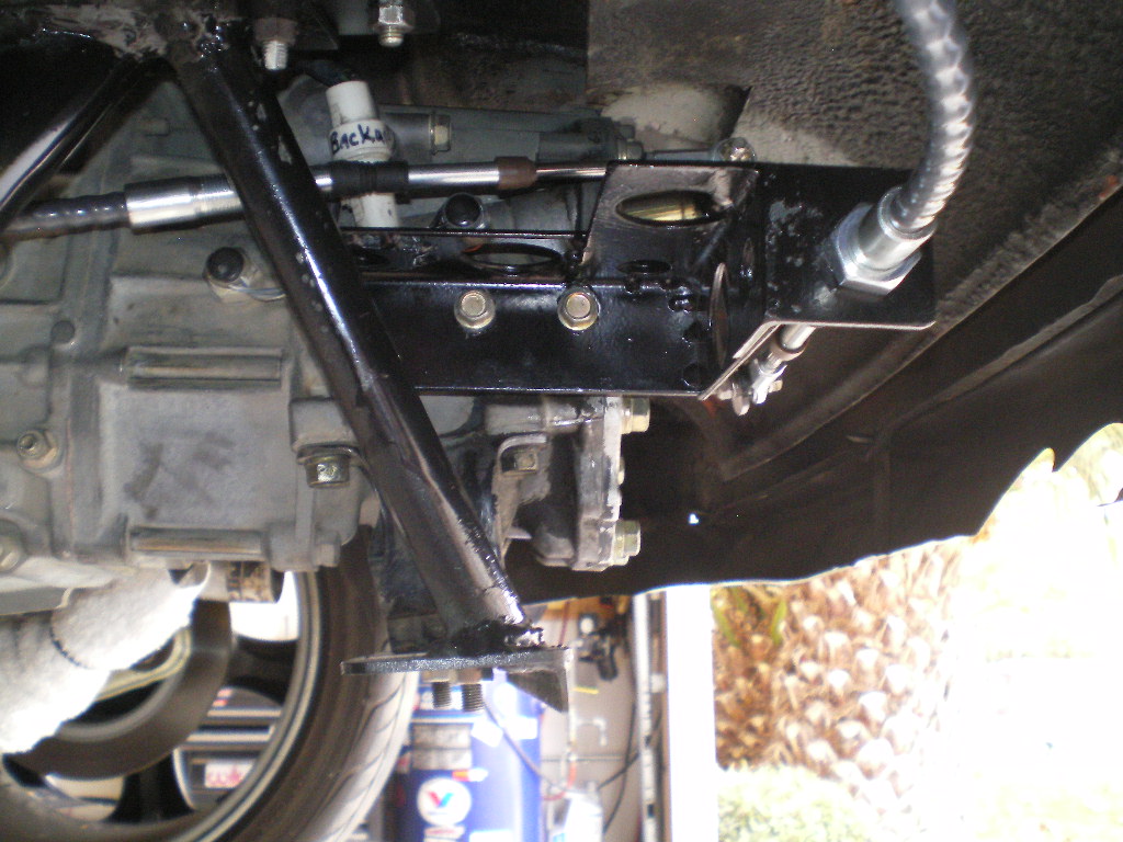
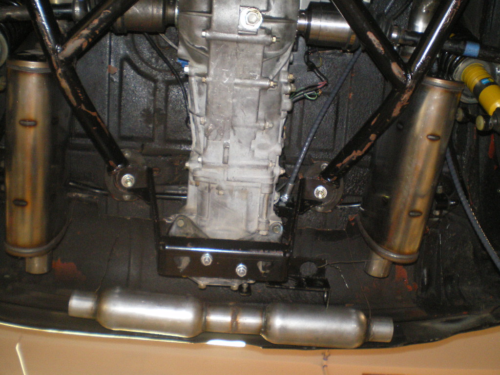
Well it's been 5 weeks and I wish I were further along but I can see the light at the end of the tunnel. I did shit can the engine as it needed a new tensioner which meant all new tensioners, guides and guess what chains weren't available. Given it had over 200K on the clock it was off to San Diego for an $850 JDM replacement motor. And since I'd pulled the drivetrain I bought one of Ian's (Cold Water Inc) cradles. I'd seen his newest design which allows for the removal of the transmission , should the need arise, while leaving the engine in the car. It had winked at me and the welds were a work of art so I took the plunge and scraped mine. So far I like his cradle more than mine in every respect except one. I'll get to that later.
First thing is to bolt it in place. Now is the time to discover any gotchas before mounting the drivetrain on the cradle only to find it won't bolt up to our car. And it did bolt right up.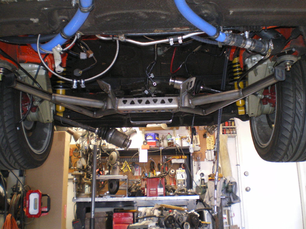
I should have left it as it was but I had to paint it. I regretted this later as I didn't let it cure and scraped it off in a few places. I'll touch it up later.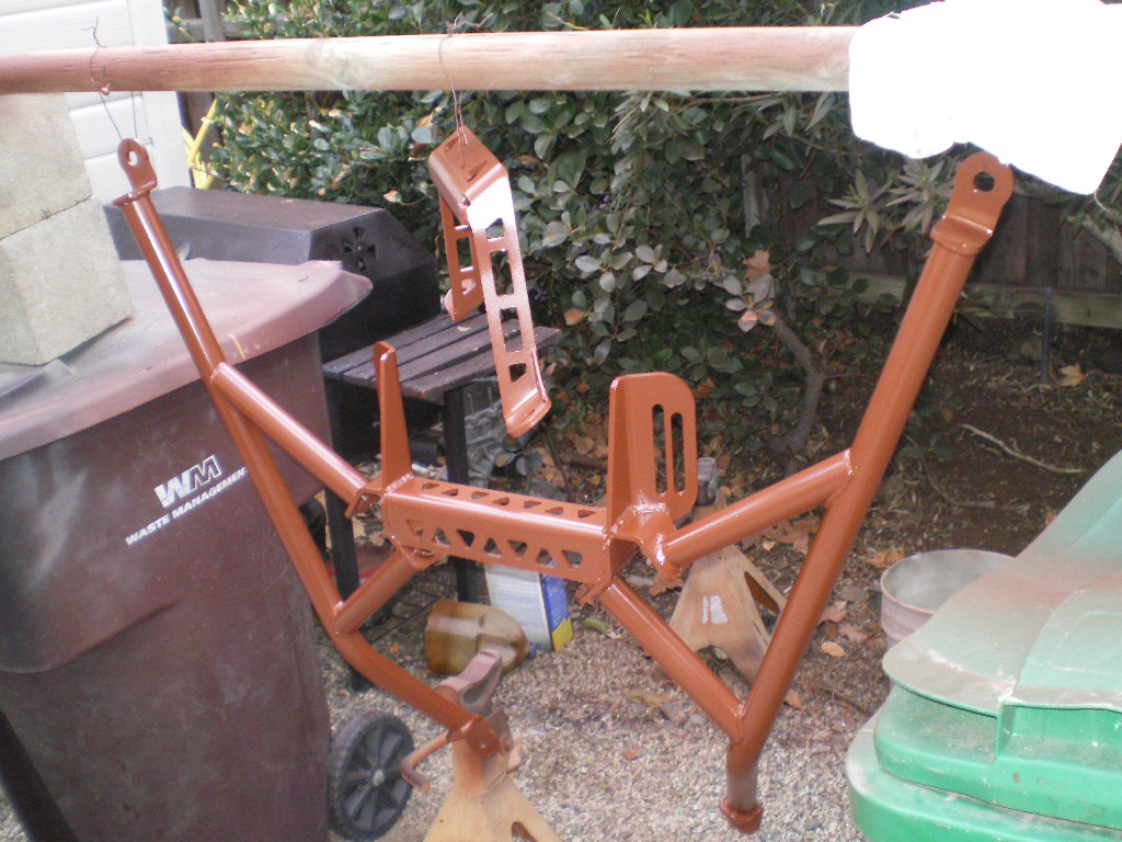
Ian's cradle doesn't have wheels or a place to mount any so I sat it on 3 furniture dollies and tied the 3 together with some 1x2's. I also placed a few 4x6's between the cradle and dollies to raise it a bit. Otherwise the car needs to sit too close to the ground during hook up. Then you just roll it in place and attach it to the car with the supplied hardware. The cradle has about 3" of front to back adjustment. I went with it midpoint. That gives me about 2" clearance where the harness' join which is a tight area otherwise. It also gives you a little more clearance around the starter connections.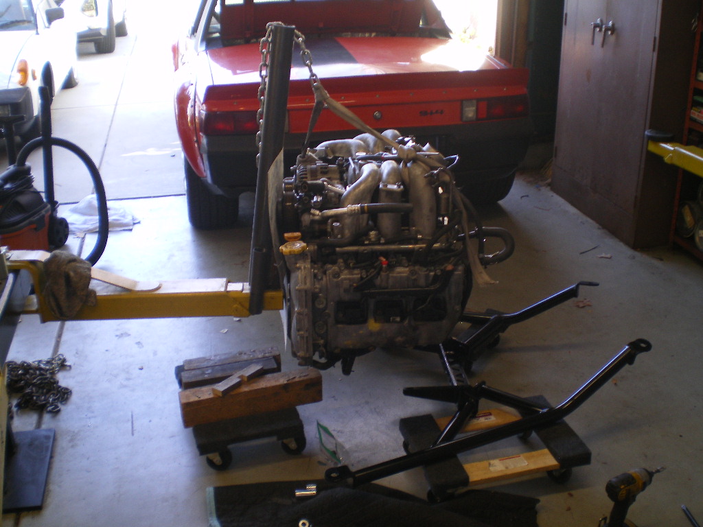
Posted by: 76-914 Feb 24 2021, 09:34 PM
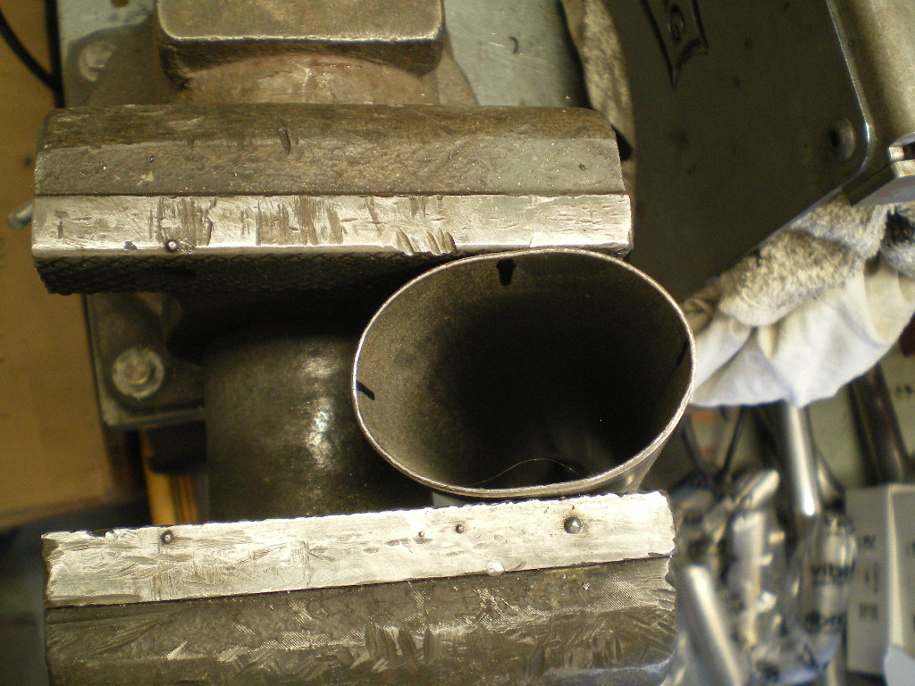
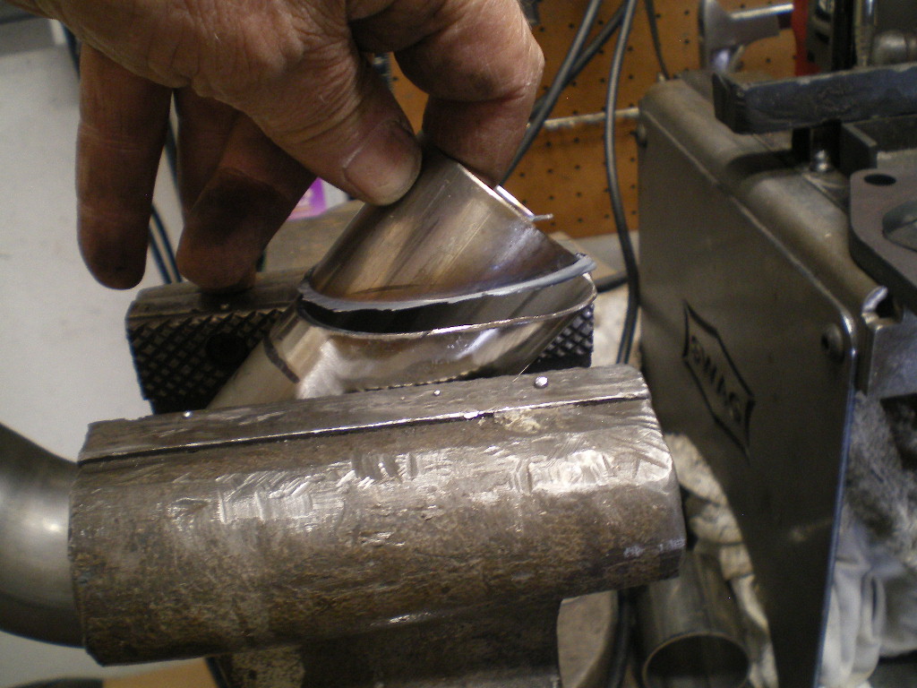
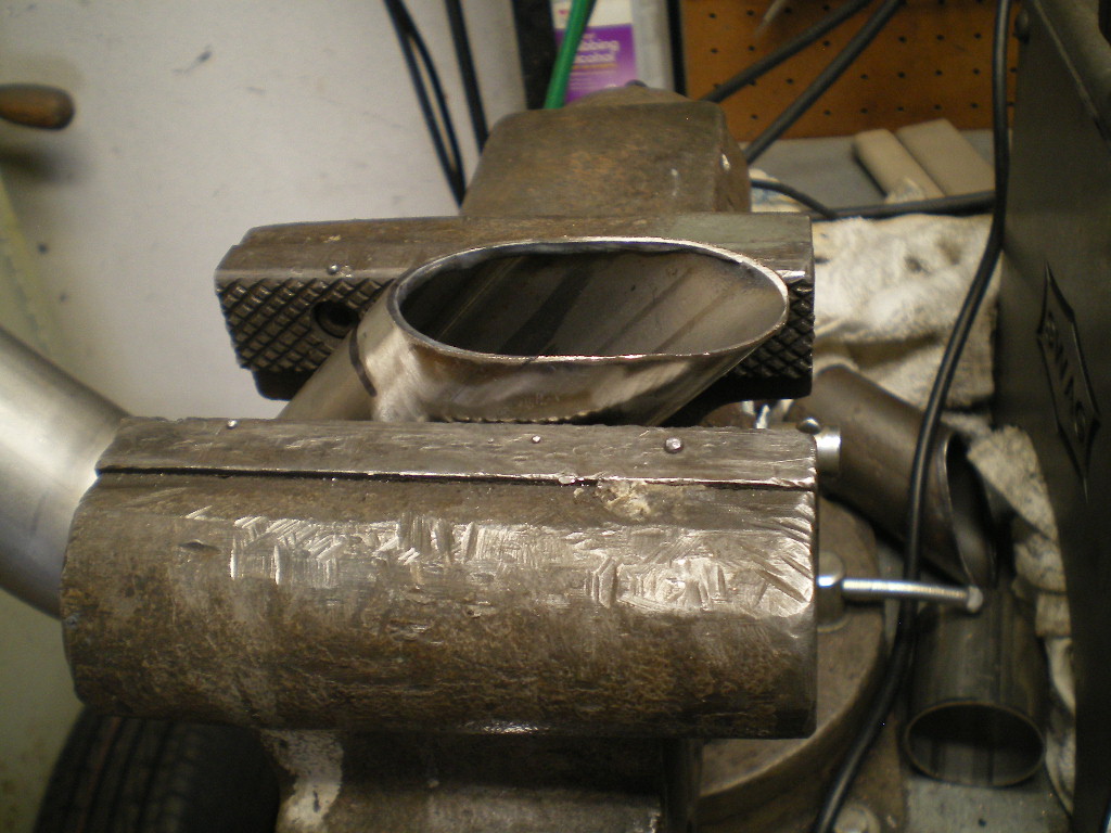
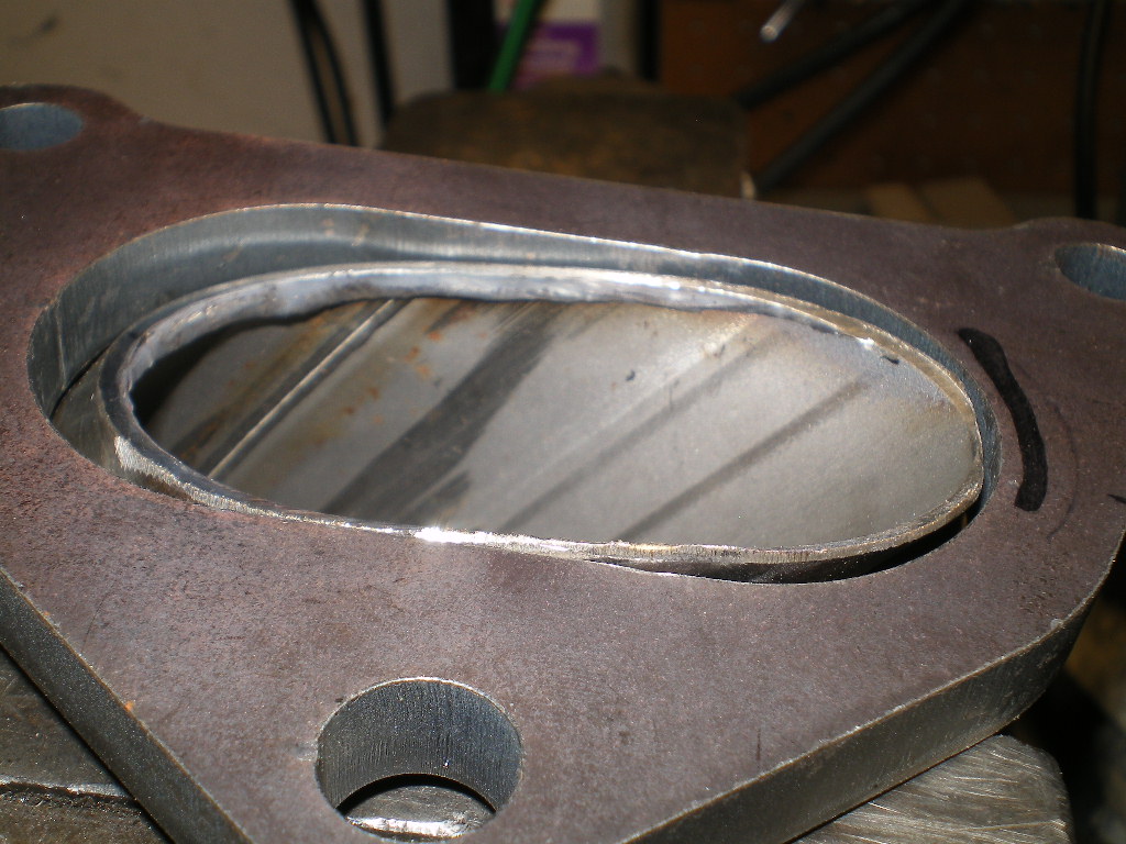
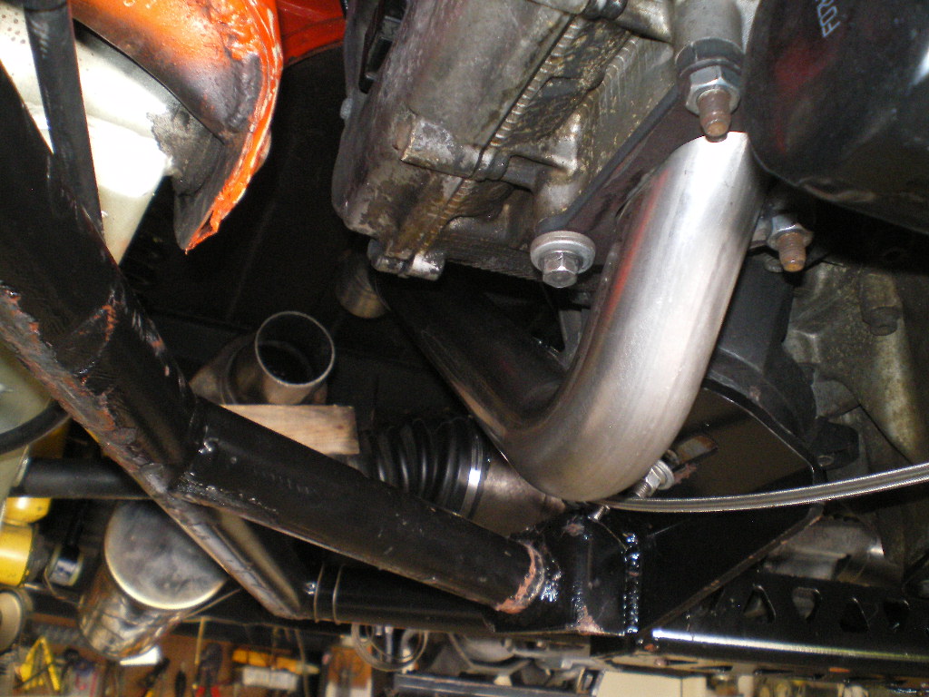
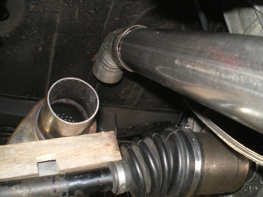
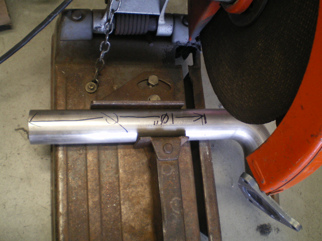
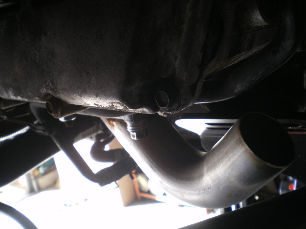
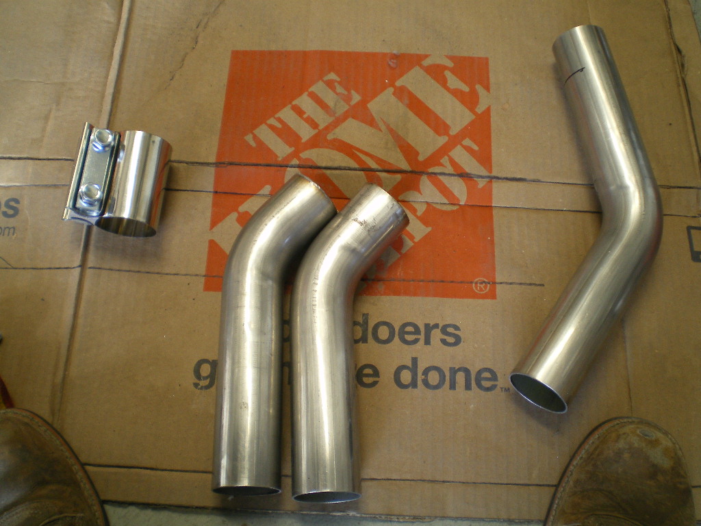
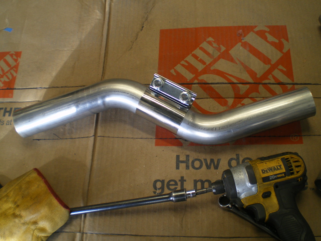
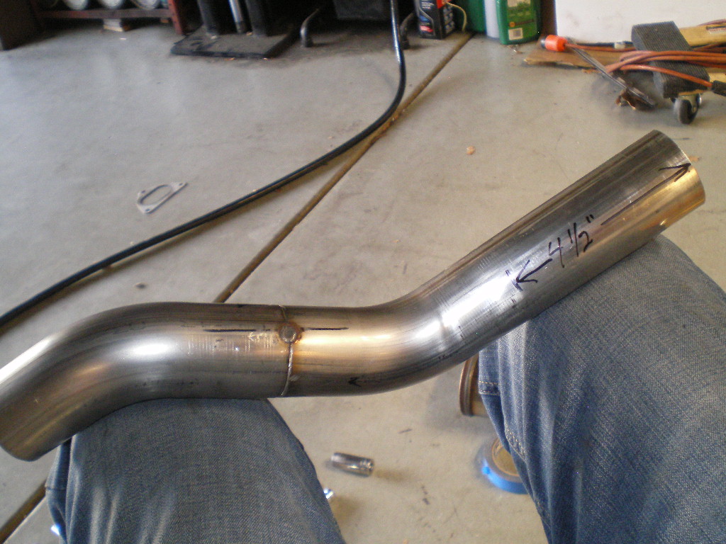
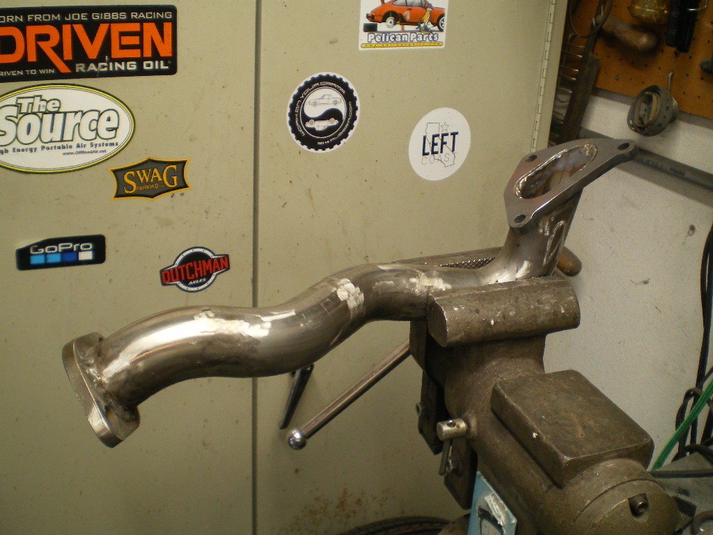
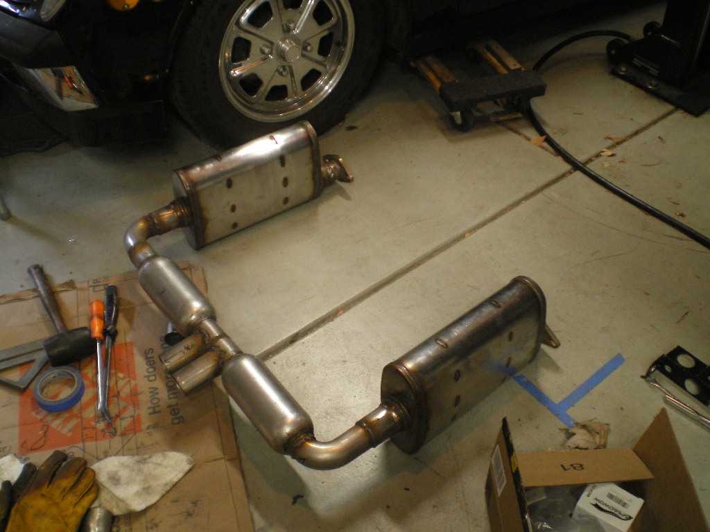
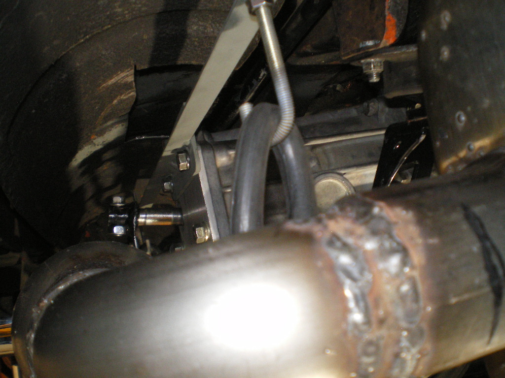
So the newest engine runs great, pulls strong and is loud as Hell which brings me to this chapter. Time for an exhaust system. I really like the exhaust system I have on the '73 so I duplicated that original order and went about installing it yesterday. You remember me saying there was one thing I didn't like about Ian's cradle? Well this is it. I can't use the same install method as he has a brace that interferes with how I installed the exhaust on the '73 using my cradle. Hopefully I'll be able to use the same combination of mufflers and keep the center out design but I had to order some additional fittings before I could go any further today. I'm using all 16ga SS so it will be good for many, many years. Her are some pif's of where I left off today.
Attached image(s)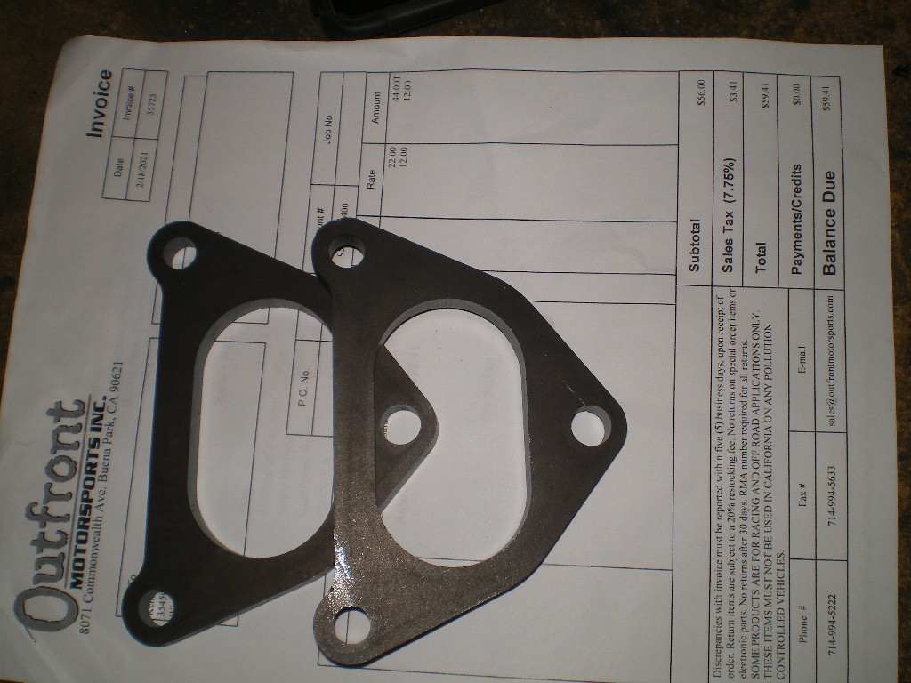

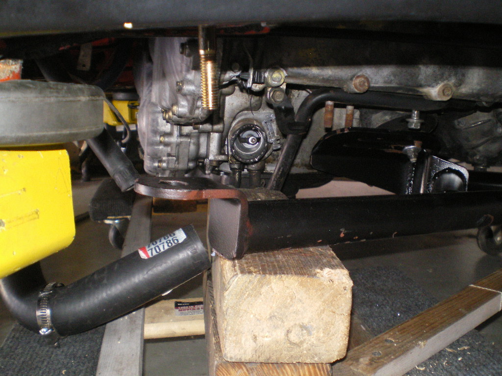
Posted by: 76-914 Apr 23 2021, 09:46 PM
Whoa. I need to update this thread, I've been posting most of this water cooled stuff on FB as there isn't much interest, and rightfully so, here. Most of the water cooled crowd has seen this stuff on FB so So I'll just do a quick pictorial explanation and if you have any questions let her rip. I finished the exhaust, relocated the intake 90 and e'welded the hole, changed the clutch MC reservoir to a smaller and nicer unit, blew out the OEM rear transmission mounts, modified Ian's cradle, etc.

Posted by: 76-914 Apr 23 2021, 10:01 PM
Posted by: 76-914 Apr 23 2021, 10:11 PM


Posted by: mgp4591 Apr 23 2021, 10:44 PM
Nice photo dump! Did you modify the trans hanger as well?
Posted by: 808 WRX Apr 23 2021, 11:17 PM
Looking good!
Which water cooled FB group are you posting on, because I am missing out!
Those rear mounts must have created some excitement! Did they pull all the way through, or were you using the upper stops?
What were you using to mount the cradle at the front before? And what will you be using to mount it (front and rear) in the future?
Thanks!
Posted by: Chris914n6 Apr 23 2021, 11:43 PM
Confused how the 914 trans mounts fit into this. Doesn't the cradle use Subaru eng n trans mounts?
Posted by: 76-914 Apr 24 2021, 10:09 AM
Nice photo dump! Did you modify the trans hanger as well?
Actually the transmission hanger was the only thing I modified; this time!
 I almost forgot to post a pic of the clutch MC that I mentioned. Solid, light weight billet aluminum. Available in several colors.
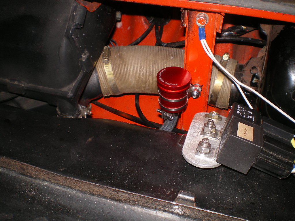
Posted by: 76-914 Apr 24 2021, 10:15 AM
Looking good!
Which water cooled FB group are you posting on, because I am missing out!
Those rear mounts must have created some excitement! Did they pull all the way through, or were you using the upper stops?
What were you using to mount the cradle at the front before? And what will you be using to mount it (front and rear) in the future?
Thanks!
Mostly in the "Watered Down 914's" group. I cross post in Subaru Powered Porsche's and occasionally Outlaw 914's. They pulled all the way through. The front remains the same. The cradle mounted to 2 pieces, one on each side, of 1/4" plate steel. Those plates sit atop the ledge where the OEM engine bar once mounted and use the same 2 8mm bolts to secure them in place.
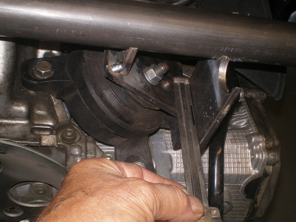
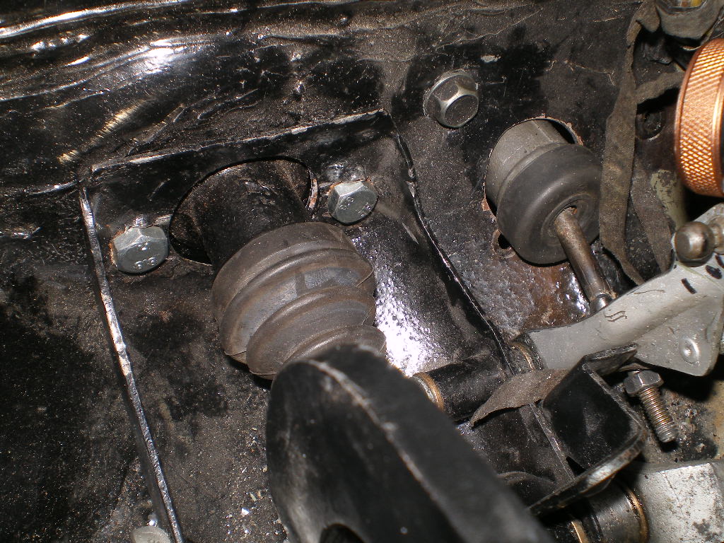
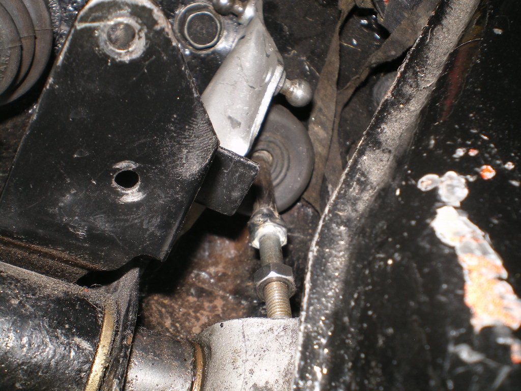
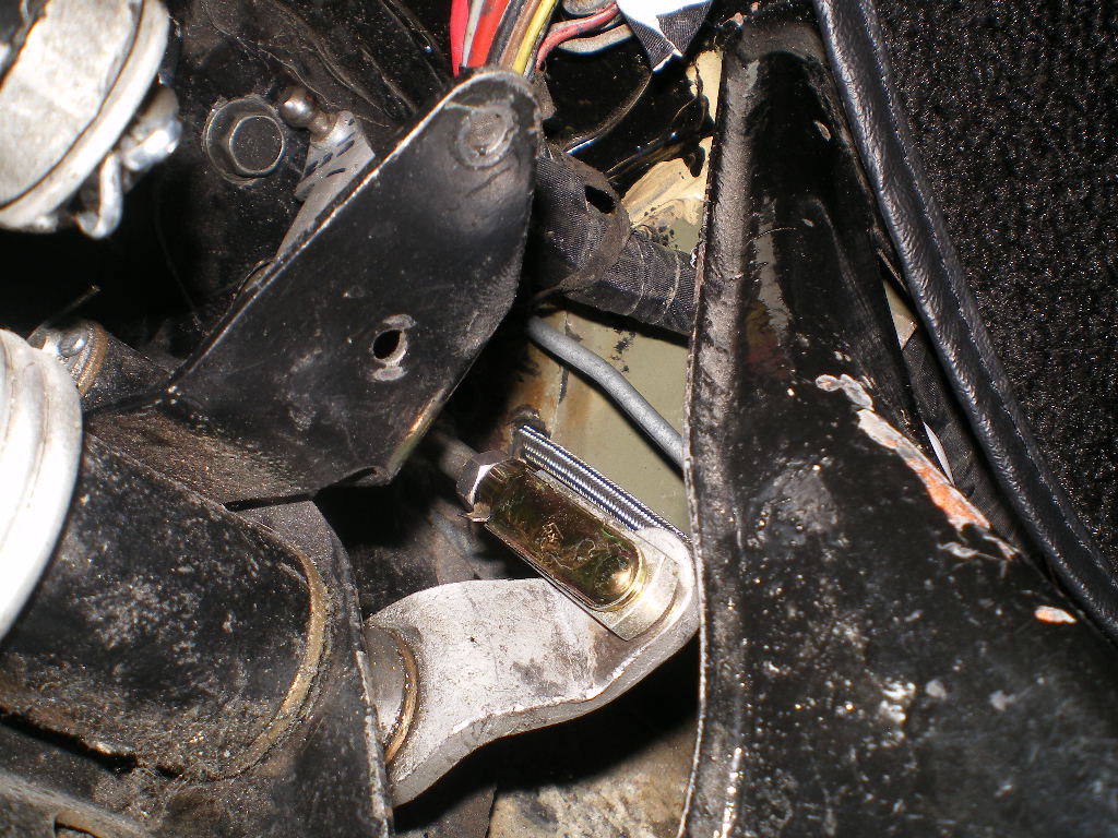
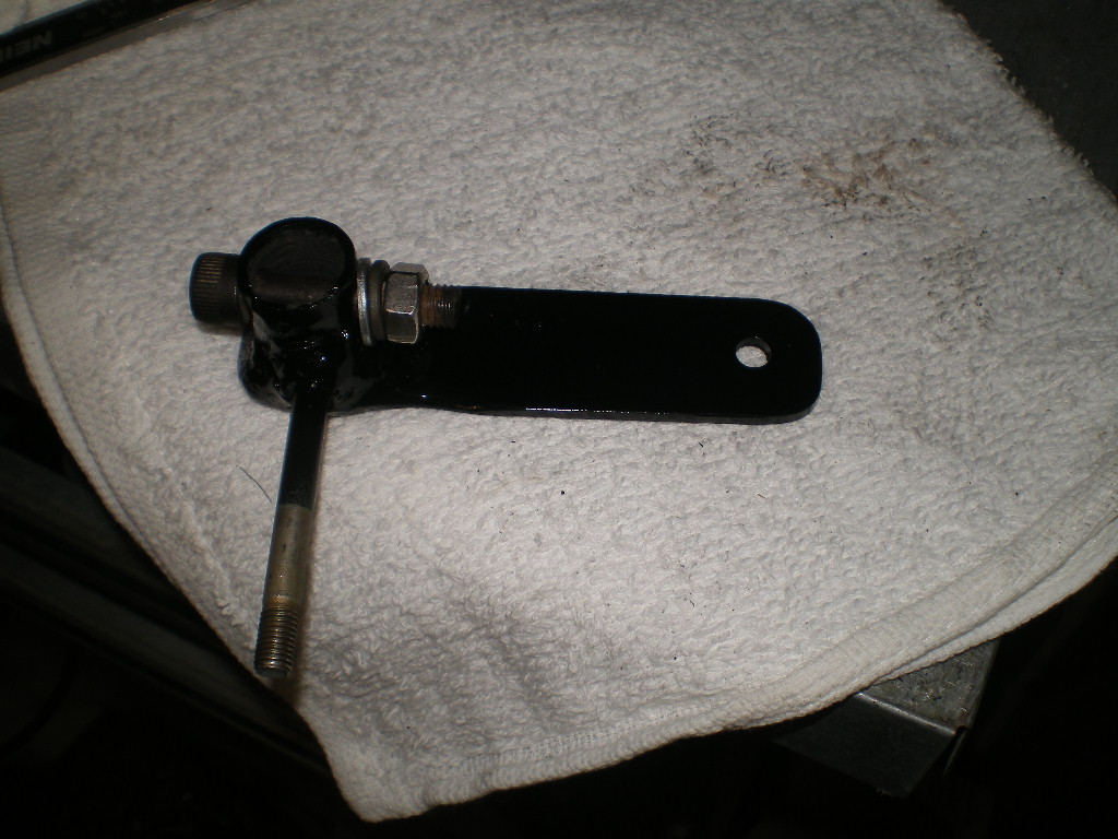
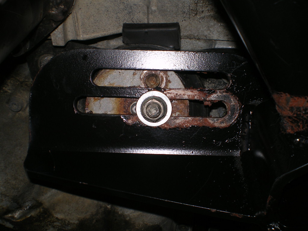
Posted by: 76-914 Apr 24 2021, 10:26 AM
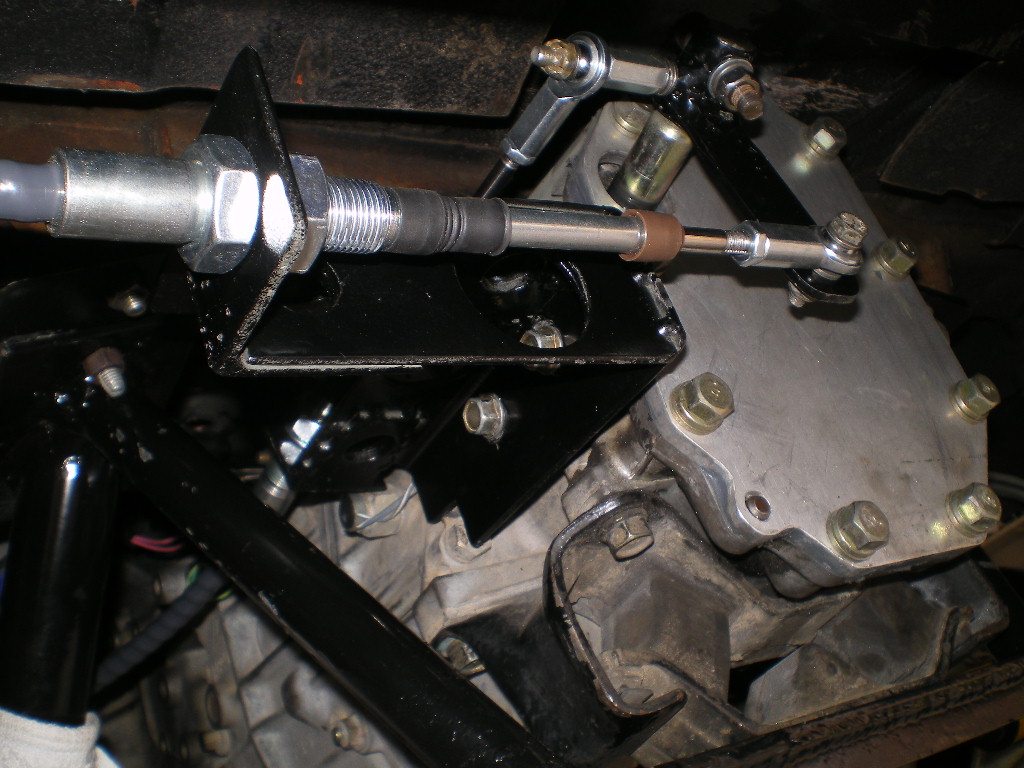
Confused how the 914 trans mounts fit into this. Doesn't the cradle use Subaru eng n trans mounts?
Chris, the mount has slotted plates that the OEM Subaru mounts sit upon. You can vary the engine location ~3" front to rear. If using an EZ30 the engine should sit as far back in the slots as possible however that causes fitment problems at the trunk bulkhead. I shifted my engine midpoint but in doing so that throws the transmission hanger out of kilt which resulted in a 22.5 degree misalignment between the base of the OEM Subaru transmission mount and the hanger. It is possible to "pull" it into position so that it holds but it looked like crap. So I modified the hanger. Hopefully his future cradles will employ the same adjustable slotted flanges on the transmission hanger as well. Here are some before & after pic's.
Posted by: mgp4591 Apr 24 2021, 08:42 PM
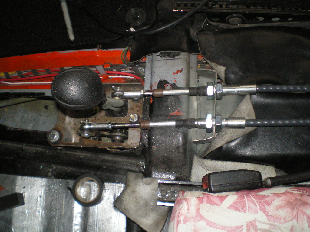
Looks like you had to modify your shift cable mounting bracket as well...I see 2 12mm holes and 2 bolts in a different location. Yeah... the bolts have 12mm heads but they're only 8mm bolts.
Posted by: 76-914 Apr 24 2021, 10:48 PM
Looks like you had to modify your shift cable mounting bracket as well...I see 2 12mm holes and 2 bolts in a different location. Yeah... the bolts have 12mm heads but they're only 8mm bolts.
I did try relocating it to clear an earlier exhaust attempt. That didn't go well ad I went back to the original holes. Good eye Michael.
Posted by: Mayne Apr 25 2021, 08:07 AM
Everything looks great! Thanks for continuing to post on this thread. I follow your posts on FB, but I find it difficult to go back and look for previous posts. Here, it’s all in one place.
I think I saw you’re going to be on the RT66 drive. I’d love to see your car in person and talk about the conversion. Cheers!
Posted by: 76-914 Apr 29 2021, 07:25 AM
If the Wx is hot I'll bring the black one Jeremy; it has AC. Short of repairing the flashers I'm done with the inside. The shifter console is wrapped to match the dash face material and there's not much left to do other than drive it and tweak any anomalies that pop up. On the highway temps have been a steady 183F. Fans have yet to kick on but I expect with these warmer temps they will in stop 'n go traffic. I need to come up with a trunk prop. Something akin the current day engine hood props. And I'll probably carpet the trunk. And decals; I want to throw a bunch of retro decals on it. 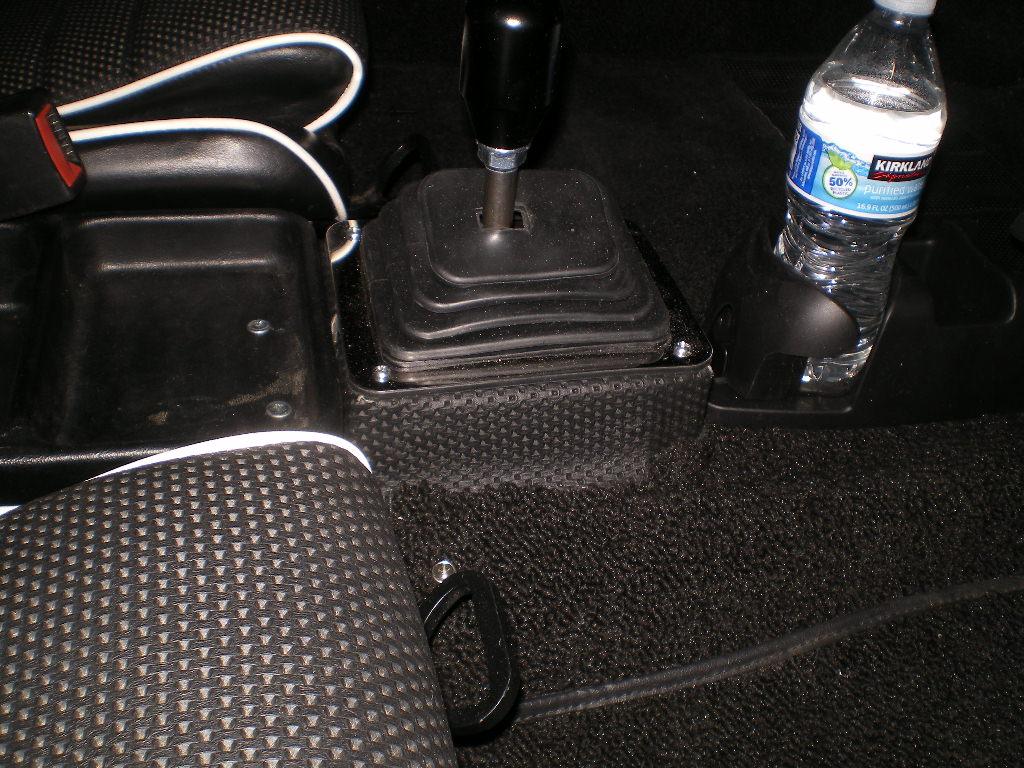
Posted by: mgp4591 Apr 30 2021, 12:27 AM
Add some washers under your hood hinges to let the hood vent your heat from the radiator... that's how we did it back in the low budget days and it worked!
Posted by: rmarx Apr 30 2021, 10:40 AM
Looking good Kent! I will try and head south in the next couple months to check your car out.
Posted by: cali914 Apr 30 2021, 02:54 PM
Kent you are doing some fantastic work on that 914
Posted by: euro911 Apr 30 2021, 03:12 PM
Nice work, Kent 
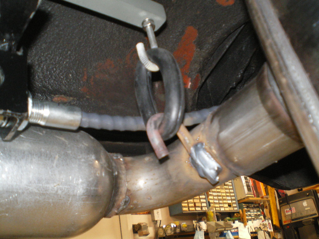
May I make a suggestion? ... You might want to smooth out the threads on your exhaust hanger - the threads might cut through the rubber O-ring over time 
Posted by: 76-914 May 15 2021, 06:33 PM
Sorry guys. I was busy and missed your replies:
@http://www.914world.com/bbs2/index.php?showuser=14748 That's clever Michael. I'll keep that in mind. I may end up ducting the radiator like I did on the other one. But before I go that far I'm going to weld in a patch piece to reduce that huge air inlet that was to cool the V8. I know from past experience that the standard Porsche oil cooler opening is large enough to properly cool the 3.0.
@http://www.914world.com/bbs2/index.php?showuser=7784 Sounds good. Just PM me for my address whenever you get around to that.
@http://www.914world.com/bbs2/index.php?showuser=5934 Thx Harry. Did you get that EcoTech tamed?
@http://www.914world.com/bbs2/index.php?showuser=7300 I thought the same thing MarK. I tried to get a piece of heat shrink over those threads and finally gave up. Then it dawned upon that yes those threads will dig into that rubber but they can only cut into it the height of the threads. After that the rubber ring is resting in the valley's of those threads. BTW, in case I'm wrong I carry some baling wire in my tool box for emergencies. See you at Rt66.
Posted by: 76-914 Sep 29 2021, 09:34 AM
This has been on my "to do list" for months. (So long that I forget from whom I purchased my donor part. Maybe BKranz?? Anyway it was exactly as described - thank you.) As you know this project had a V8 when purchased and the typical Renegade radiator cutout. Since replacing the V8 with a Subaru 6 that large opening isn't needed and I will decrease the size of the opening to match a previous build. I suspect that an overly large intake opening contributes to some of the "hot air into the cabin" that most H20 conversions experience to some degree or another. I eliminated that spill over in my '73 by ducting the radiator exhaust directly out the wheel wells. I'm curious as to how much this will help. Regardless this will add some stiffening and support back into that area. 
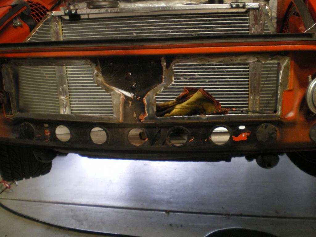
Posted by: 76-914 Sep 29 2021, 09:35 AM
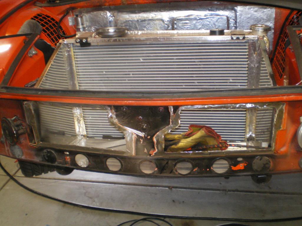
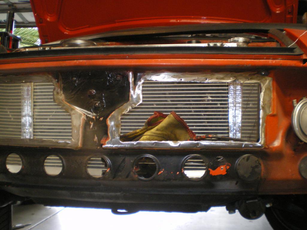
Posted by: 76-914 Sep 29 2021, 09:37 AM
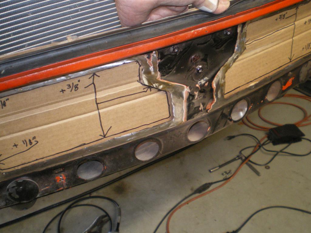
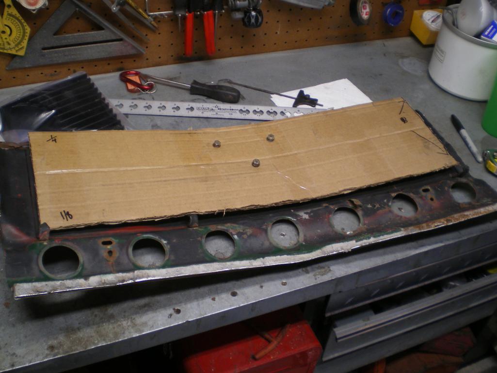
Posted by: 76-914 Sep 29 2021, 09:38 AM
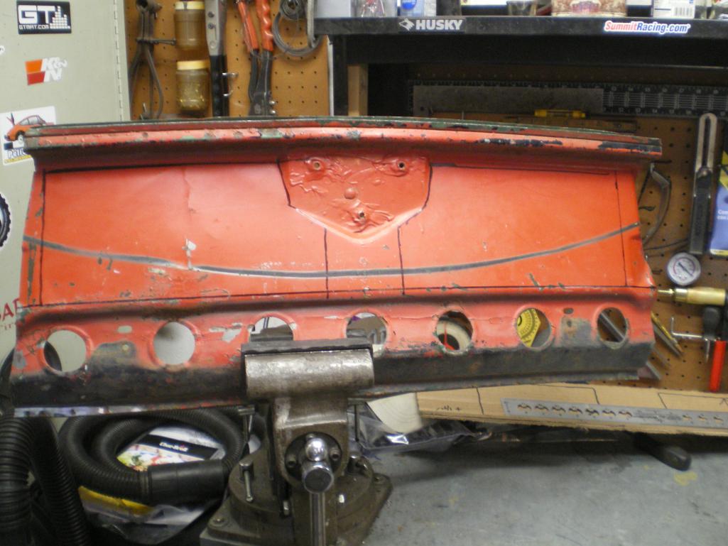
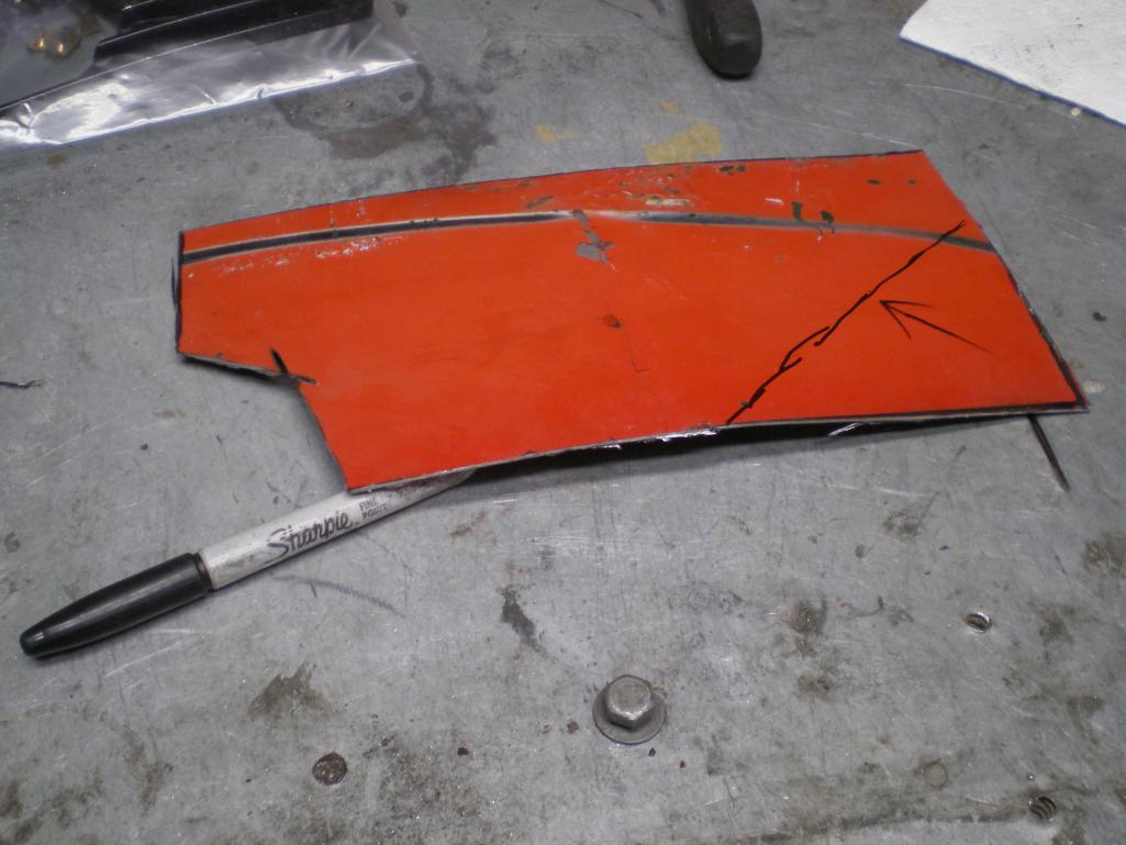
Posted by: 76-914 Sep 29 2021, 09:41 AM
Oddly enough, this piece revealed a crease once it was cut away from the donor part. No problem as it was easy enough to hammer out. I drew a line across the crease in the pic above. This is the backside but it is still visible.
Posted by: 76-914 Sep 29 2021, 09:47 AM
Cleco's & patch piece's in place for final trimming. I will trim and weld them in place within the next day or 2. Currently I am serving time in the Honey Do Hotel and have been tasked with cleaning the windows and replacing the screens. 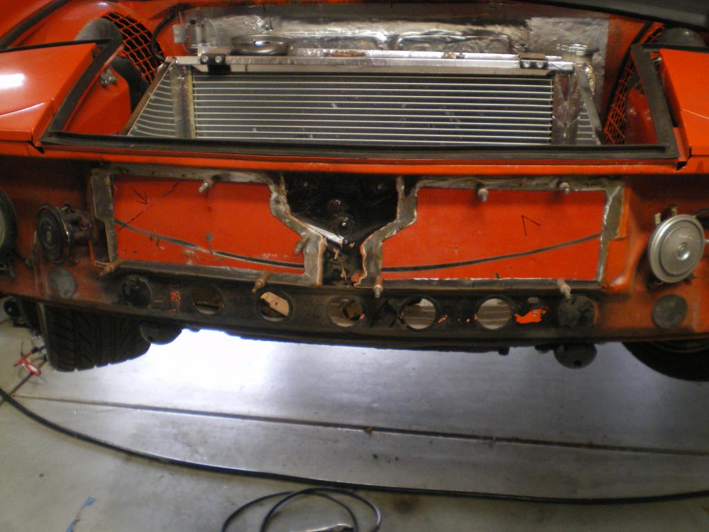
Posted by: partwerks May 14 2023, 08:14 PM
If the Wx is hot I'll bring the black one Jeremy; it has AC. Short of repairing the flashers I'm done with the inside. The shifter console is wrapped to match the dash face material and there's not much left to do other than drive it and tweak any anomalies that pop up. On the highway temps have been a steady 183F. Fans have yet to kick on but I expect with these warmer temps they will in stop 'n go traffic. I need to come up with a trunk prop. Something akin the current day engine hood props. And I'll probably carpet the trunk. And decals; I want to throw a bunch of retro decals on it.
I thought you had one that had the shifter mounted in with the stock console, and center seat cushion??
Posted by: 76-914 May 15 2023, 07:39 AM
If the Wx is hot I'll bring the black one Jeremy; it has AC. Short of repairing the flashers I'm done with the inside. The shifter console is wrapped to match the dash face material and there's not much left to do other than drive it and tweak any anomalies that pop up. On the highway temps have been a steady 183F. Fans have yet to kick on but I expect with these warmer temps they will in stop 'n go traffic. I need to come up with a trunk prop. Something akin the current day engine hood props. And I'll probably carpet the trunk. And decals; I want to throw a bunch of retro decals on it.
I thought you had one that had the shifter mounted in with the stock console, and center seat cushion??
I do. It's in the members build thread forum. http://www.914world.com/bbs2/index.php?showtopic=201776
Posted by: partwerks Feb 11 2024, 08:38 PM
So the newest engine runs great, pulls strong and is loud as Hell which brings me to this chapter. Time for an exhaust system. I really like the exhaust system I have on the '73 so I duplicated that original order a went about installing it yesterday. You remember me saying there was one thing I didn't like about Ian's cradle? Well this is it. I can't you the same install method as he has a brace that interferes with how I installed the exhaust on the '73using my cradle. Hopefully I'll be able to use the same combination of mufflers and keep the center out design but I had to order some additional fittings before I could go any further today. I'm using all 16ga SS so it will be good for many, many years. Her are some pif's of where I left off today.
What size is the exhaust pipe?
Posted by: 76-914 Feb 12 2024, 09:21 AM
So the newest engine runs great, pulls strong and is loud as Hell which brings me to this chapter. Time for an exhaust system. I really like the exhaust system I have on the '73 so I duplicated that original order a went about installing it yesterday. You remember me saying there was one thing I didn't like about Ian's cradle? Well this is it. I can't you the same install method as he has a brace that interferes with how I installed the exhaust on the '73using my cradle. Hopefully I'll be able to use the same combination of mufflers and keep the center out design but I had to order some additional fittings before I could go any further today. I'm using all 16ga SS so it will be good for many, many years. Her are some pif's of where I left off today.
What size is the exhaust pipe?
2"
Powered by Invision Power Board (http://www.invisionboard.com)
© Invision Power Services (http://www.invisionpower.com)