Printable Version of Topic
Click here to view this topic in its original format
914World.com _ 914World Garage _ Much better !!!! Fixxed the LINK FI :)
Posted by: Mueller Jul 10 2005, 04:05 PM
Got a good runner now, I'm not sure if it was due to the plugs (LINK recommended resistor type) or if it was due to my terrible and sloppy engine wiring harness.
Mike Rose came by yesterday and gave me hand with the harness, much easier with 2 people to route the wires thru the car.
LINK ECU is now mounted inside the cabin...I removed I think 6 wires completly from the harness which I have no use for in my application, I also shortened the other wires by about 3 feet.
Still figuering out the tuning thing....I think I might end up putting a TPS on it since the vac. only is a PITA at idle since my vac. signal seems to vary from 35kPa to 65kPa each time I release the throttle (1.7 intake system with stock throttle body)
Car starts and idles fine, I tried to drive it up the street and it's too lean...not sure if it was during acceleration or just under load at that particlur MAP setting.....
I'm a happy camper and I'll be even happier when I figure out how to tune the computer better

Posted by: TimT Jul 10 2005, 06:01 PM
heheh good for you Mike...
Some of those extra wires are like antenna they pick up stray electrical noise, and make havoc with the way the engine runs.
A TPS will be beneficial, as in TPS mode the ECU uses MAP besides throttle position to adjust fuel
Tune in the increments the table shows, the map I have for my car is based on 500 rpm intervals
Hold the throttle at a given rpm and adjust fuel... if the indicated cell jumps around you can adjust cells of lower and higher manifold pressure also
move to next RPM position, repeat
when you have fuel adjusted to a safe ratiosn throughout your rpm ranges.. play with timning
Posted by: Andyrew Jul 10 2005, 06:06 PM
Glad to hear it!
Gona come to the july 24th v8 meet? 
Posted by: Mueller Jul 10 2005, 06:50 PM
Hey Tim,
Yep, that is pretty much how I was tuning it...problem I am now having is that I cannot seem to get enough fuel during acceleration, I've played with the "accel" inputs and they are not doing it for me. I'll e-mail LINK and hopefully they'll be able to tell me what I am doing wrong.
I switched the setting from VACUUM to MAP and then to MAP+TPS (with no TPS) and it actually ran best at MAP+TPS  ..the accel is still wackey, but no big deal right now.
Now that I got this far, I'll pull off the throttle body and install a new TPS onto it, I'll be needing the TPS for sure with my next intake setup so I might as well learn how to tune it.
Andrew, if I'm back from Louisiana in time I'll try to make the V8 meet.
Posted by: jonwatts Jul 10 2005, 06:53 PM

Glad to hear you did it without sending everything off.
Posted by: McMark Jul 10 2005, 10:12 PM
Don't worry about acceleration and accelerator pump issues right now. Just get the cells right. No sense working the accel pump if the main map is wrong. It'll just make it harder to set the main map. In fact, you might think about zeroing the accel pump setting so that they don't screw with you setting up the main map. 
I'm planning on coming tomorrow or tuesday night for a burger and get the LM-1. Any conflict for you?
Posted by: Mark Henry Jul 11 2005, 06:20 AM
I don't know how the Link works but on my SDS accel pump works off of the TPS.
Glad to hear your making progress. 
Posted by: DNHunt Jul 11 2005, 08:38 AM
Mike
Glad to see you got it going. now keep the coffee away from it.
Dave
Posted by: Aaron Cox Jul 11 2005, 08:59 AM
| QUOTE (DNHunt @ Jul 11 2005, 07:38 AM) |
| now keep the coffee away from it. |


Posted by: Mueller Jul 11 2005, 10:59 AM
aaron should be happy...no camera phone pictures here 
LINK ECU mounted inside...once the backpad is installed it'll be hidden (I shouldn't have to access it except for massive tuning changes once setup, so no big deal if hidden away)
Attached image(s)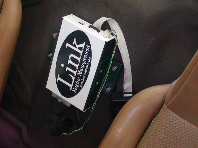
Posted by: Mueller Jul 11 2005, 11:02 AM
I had to use some resistors with the injectors due to the impedance of them (stock 2.0 injectors)
Sooner or later I'll re-do the wiring harness and use different connectors, these are GM Weaterpac connectors.
Attached image(s)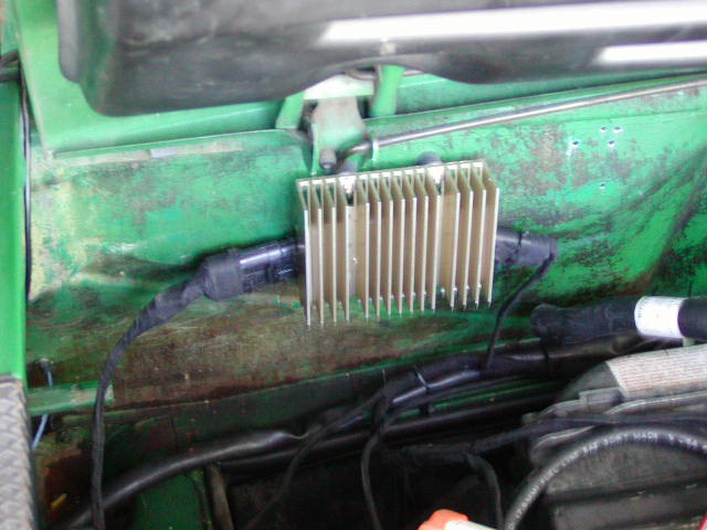
Posted by: Mueller Jul 11 2005, 11:02 AM
another view of the ugly engine compartment 
Attached image(s)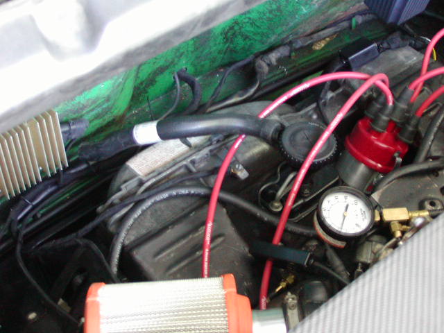
Posted by: Mueller Jul 11 2005, 11:04 AM
here is a shot of the wires removed from the harness that I did not need with this install along with the extra length of wire removed from the needed wires so that the harness was not too long.....
Attached image(s)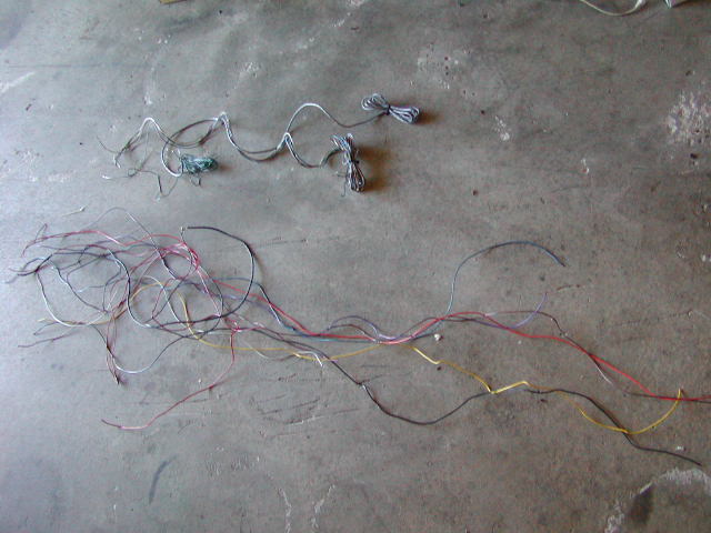
Posted by: MetricMayhem Jul 11 2005, 11:55 AM
Does the LINK have an LED for error codes on the unit or does have a lead for a dash light or neither?
Posted by: Mueller Jul 11 2005, 11:57 AM
for error codes I'd have to plug in the laptop or the pendant (which I didn't buy)
Posted by: Mueller Aug 24 2005, 06:05 PM
Update on the Link...I got the ignition problem solved, it was due to not phasing the trigger and the rotor inside the distributor correctly...
been trying to tune it today with a little luck....cannot see my laptop screen due to the sun so I'm going to wait until tonight and drive around the neighborhood to tweak it better......
Posted by: SirAndy Aug 24 2005, 06:07 PM
| QUOTE (Mueller @ Aug 24 2005, 05:05 PM) |
| I got the ignition problem solved |
Posted by: Mueller Aug 25 2005, 12:30 AM
| QUOTE (SirAndy @ Aug 24 2005, 05:07 PM) | ||
|
I ended up using a homemade rotor electrode, L-shaped
1st picture is at idle (10°advance)
Attached image(s)
Posted by: Mueller Aug 25 2005, 12:31 AM
top view of distributor
at about 2000rpm the rotor and the HT lead line perfectly
Attached image(s)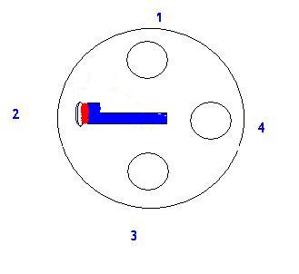
Posted by: Mueller Aug 25 2005, 12:32 AM
at max advance, 27° right now for tuning
Attached image(s)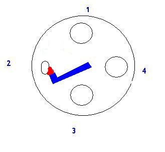
Posted by: jonwatts Aug 25 2005, 12:53 AM
That's a cheesy looking electrode, but if it works then 
Posted by: Mueller Apr 19 2006, 01:12 PM
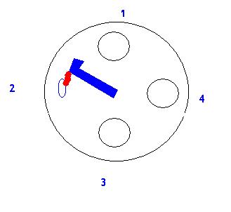
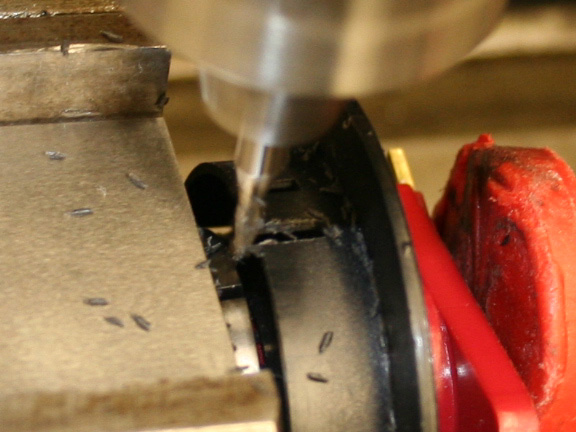
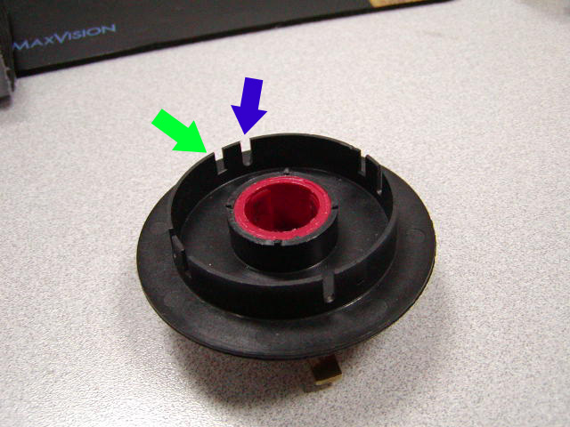
After having an ignition related failure way back in November, I have not touched my 914...until last night....in order to get the ignition correct, the trigger needs to be 10° BTDC. The Mallory rotor has a fixed trigger wheel relative to the electrode so I machined new slots and will fill in the old ones.
Hopefully you can see the 5° marks on the rotor..the little red dot is a laser for finding edges or centerlines.
Blue arrow is new slot...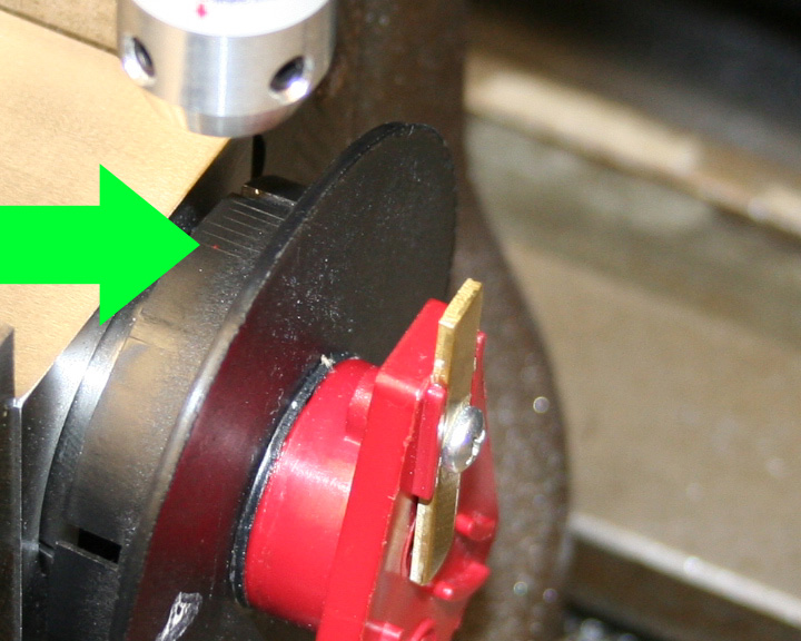
Posted by: Aaron Cox Apr 19 2006, 01:14 PM
thats allota work, and now you gotta fill the old ones....
thats gonna suck to do it every time you change a rotor -
why not just go crank fire?
Posted by: Mueller Apr 19 2006, 01:20 PM
I want to get it running good this way....I'll convert to crankfire on my other motor that is sitting on my workbench....
LINK recommends MSD instead of Mallory, I'm guessing it might be easier with the MSD dizzys to alter the trigger event relative to the center electrode.
Powered by Invision Power Board (http://www.invisionboard.com)
© Invision Power Services (http://www.invisionpower.com)