Printable Version of Topic
Click here to view this topic in its original format
914World.com _ 914World Garage _ D-Jet ECU Tuning (*** WARNING Extreme Tech Geekiness ***)
Posted by: Not_A_Six Aug 21 2020, 02:58 PM
I've recently gone down the rabbit hole of D-Jet and MPS tuning and wanted to post what I've learned in the hopes that it may help others. I also hope to start a discussion with some of the experts here in case I've missed something, or there are errors in my analysis. 
Background:
With the increased displacement (2056cc) and non-stock cam (Webcam 73) in my engine, I was experiencing Air-Fuel Mixture (AFR) issues across the range of temperature, load, and rpm conditions. 
This thread concerns ECU tuning. Related threads that may be of interest are:
http://www.914world.com/bbs2/index.php?act=ST&f=2&t=348044
http://www.914world.com/bbs2/index.php?act=ST&f=2&t=347291
http://www.914world.com/bbs2/index.php?act=ST&f=2&t=347986
In general, the MPS can be tuned to affect the AFR vs Manifold Vacuum, and the ECU can be tuned to affect AFR vs engine RPM. I was having idle instability problems (fixed by replacing the PCV valve with a modern one), a lean "flat spot" at around 8 In-Hg vacuum (fixed by tuning the MPS), and another lean "flat spot" at around 4600 rpm (attempting to fix by tuning the ECU as described in this thread).
Engine Configuration:
'73 2.0
Displacement: 2056cc
Cam: Webcam 73
ECU: Porsche nnn906021E (Bosch 280000037)
MPS: Porsche 022906051E (Bosch 0280100049) w/ Tangerine Racing tuning kit + spacer ring. Originally tuned to emulate 0280100037. http://www.914world.com/bbs2/index.php?s=&showtopic=348044&view=findpost&p=2844174.
CHT: 0280130017 w/ 270-ohm ballast resistor and steel spacer
Vacuum Hoses routed per Jeff Bowlsby (see link below)
Fuel Pressure: 29 psi
PCV: http://www.914world.com/bbs2/index.php?act=ST&f=2&t=347986
Ignition: http://www.914world.com/bbs2/index.php?act=ST&f=2&t=347291
Timing: 27 degrees at 3500 rpm (w/o vacuum adv/ret)
Equipment used:
Generic handheld vacuum pump/gauge
misc hoses+fittings
HP 54600A Oscilloscope
Fluke DMM
Innovate Motorsports (3837) LM-2 (BASIC) Digital Air/Fuel Ratio Wideband Meter w/ Bosch LSU 4.9
Home-fabricated tailpipe "Stinger" w/ O2 Sensor Bung TIG welded on
Assorted Resistors and Potentiometers
Assorted Test Leads
Reference Info:
https://bowlsby.net/914/Classic/zTN_FI_Hose_Vac_2.0L_Late1974_A.jpg
https://members.rennlist.com/pbanders/ecu.htm @http://www.914world.com/bbs2/index.php?showuser=805
ECU Schematics (Also by Brad Anders):
https://members.rennlist.com/pbanders/ECU1.jpg
https://members.rennlist.com/pbanders/ECU2.jpg
https://members.rennlist.com/pbanders/ECU3.jpg
Disclaimer:
All of the tuning I've done with the ECU, MPS, PCV, etc. has been for my particular car with the modified engine configuration described above. I don't recommend that anybody else try this. The components, values, tuning settings, etc. are not intended to be used for any other car. Other posters here certainly have more knowledge and experience than I do. I'm posting here in the hopes that others may find it interesting or useful. Make changes to your own cars at your own risk.
Procedure:
The D-Jet ECU is "tuned" at the factory by selecting component values to match the fuel injection pulse duration to the Volumetric Efficiency (VE) Curve of a particular engine. Modern ECU's would call this a "map", but the D-Jet system is 50 years old -- it has no CPU or memory to store data. It's a primitive, analog, transistor-based, speed-density, open-loop circuit. I highly recommend Brad Anders link above for a detailed description of its operation. 
After tuning the MPS to adjust the AFR across the range of Manifold Pressures, I was still left with a flat spot at about 4600 RPM at Wide-Open Throttle (WOT). This was because the VE curve of my modified engine differed from the stock 2.0 that the ECU was originally tuned for by Porsche/Bosch. The easy way to "fix" this is to adjust the MPS or fuel pressure to be over-rich at low rpms, in order to avoid going over-lean at high rpms. By tuning the VE curve inside the ECU for a modified engine, you should be able to flatten the AFR across the entire RPM range instead. 
Below you can see the signal at pin 10 of the MPS with the car idling. This signal is used by the ECU to turn off the fuel injection pulse, and thus sets the FI pulse duration. Conveniently, it can be measured with the car running and without opening the ECU box. As shown, it incorporates the effects of both the Speed Correction (SC) and Idle Mixture (IM) sub-circuits. It's the SC circuit that we're interested in here. See the "ECU" and "Sheet 3" links above for details. It is also shown as node "15" on sheets 1 and 3 of the schematics.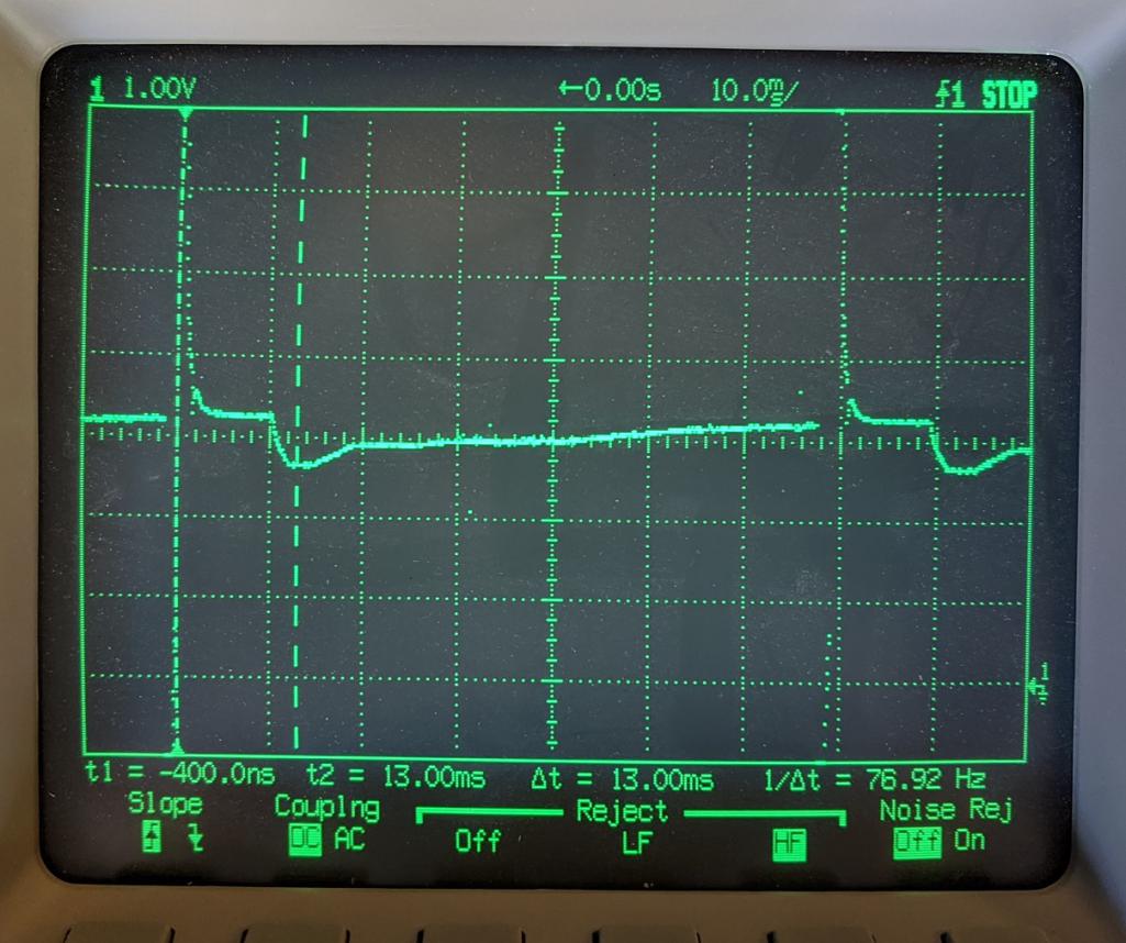
After trickling through the MPS part of the circuit (see Sheet 1), that signal affects the threshold voltage at the base of T201 (also Sheet 1) that turns off the following fuel injection pulse at the appropriate time, setting the FI pulse duration for a particular RPM. Again, see the "ECU" link for details. This is how the VE curve "map" is captured by the ECU. 
You can relate engine RPM to time on that signal with this simple formula:
Time = 60/RPM
I wanted to change the AFR via the VE curve at 4600 rpm. This equates to 13mS from the trigger on the trace above. You can see the scope cursor has been set to that time.
We can zoom in on that region of the curve (let's call it pic 1):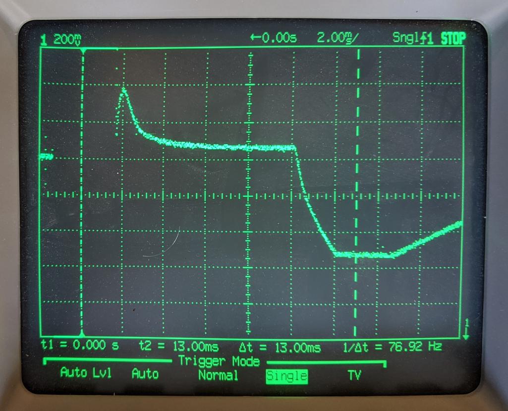
Here is the corresponding SC graph from Brad Ander's link above:
It looks like that to change the VE curve around 4600 rpm (around 13mS on the scope photo above), the "Wfm4" (red) value needs to be changed.
If you wanted to change the VE curve at some other RPM, you'd need to determine which Wfm sub-circuit to modify.
On Schematic Sheet 3, you can see that the Wfm4 signal is created at the anode of D119 by the voltage divider formed by R162 and R161. (Kerfoot's schematic mis-labels R161 as R163). The stock value of the voltage at this node is 4.8V (assuming 12V at the ECU power pin). The stock value of R161 is 2K; the value of R162 is 3K.
I wanted to richen the AFR in this region of the curve, which can be accomplished by reducing the voltage at this node. This, in turn can be accomplished by changing the value of either R161 or R162. I decided to change the "effective" value of R161 by connecting another resistor in parallel with it. This saved me from trying to un-solder a part from a 50-year-old PC board, and allowed me to temporarily connect a potentiometer and tune the value while driving.
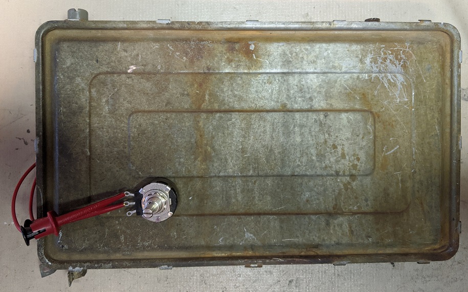
Here you can see the ECU disassembled on the bench. R161 is on the lower board, in the bottom left section.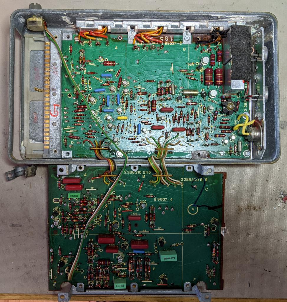
To allow in-car tuning with a wideband O2 meter, I temporarily wired a 50K potentiomenter in parallel with R161. This lets me vary the parallel equivalent resistance of the pair in the range of 0 to 1.9K. Here you can see the setup ready to put back in the car. 
The next step was to test drive, making adjustments with the potentiometer until I got the AFR wanted at the RPM wanted. I ended up satisfied with a value of 15K on the pot, which corresponds to an effective value of 1.765K for R161, and makes the voltage at the anode of D119 now 4.44V instead of 4.8V. 
Here you can see the Node 15 signal with a 10K pot value. Let's call it pic 2. (The dip in the curve vs stock with a 15K resistor is a bit less extreme, but I didn't get a pic):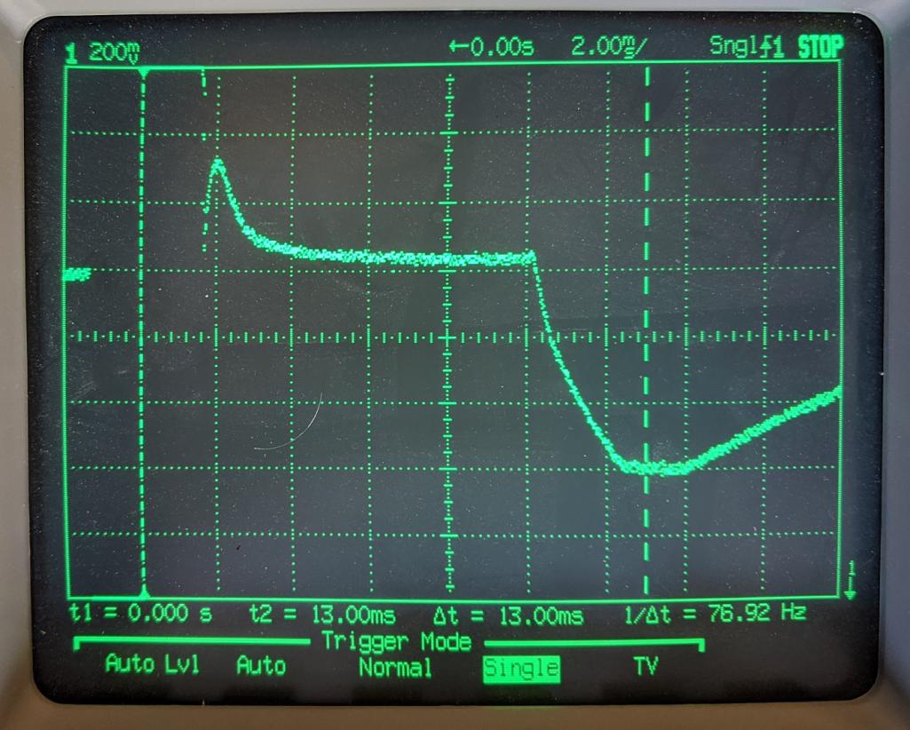
If you compare Pic 1 and Pic 2, you can see that the SC curve has been changed slightly in the region of about 10-17mS from the trigger one division from the left of the screen. Hopefully, this will correspond to richening the AFR near 4600 rpm.
The last step was to pull the ECU back out to the bench, remove the pot, and solder a permanent 15K resistor in parallel with R161. (Again, I didn't want to un-solder a part on such an old PCB, so I soldered the 15K resistor directly to R161.)
The end result of all of this is that AFR is hopefully tuned for the modified engine across manifold vacuum and rpm ranges. Driveability is good, but I'm still fine tuning. This was way more involved than I initially thought. The ECU mod, in particular, is not for the faint of heart. And, D-Jet is old and primitive. The changes you can make via the MPS and even the ECU are limited. If I had to do it all over again, I think I would have gone with a Microsquirt system when the engine was rebuilt. 
I hope somebody finds this useful, or at least entertaining. Comments and suggestions are most welcome. 
Cheers. 
Posted by: Krieger Aug 21 2020, 11:21 PM
Wow! You really dug into it! Now drive the dang thing!
Posted by: Arno914 Aug 22 2020, 04:48 AM
Great article, very interesing indeed. Thanks for sharing!
You guys probably know the site from Volker alias "Mr. D-Jet". I attendet one of his famous workshops here in Germany two years ago with the 914 club of germany. What a great day that was.
His site is even in english:
https://jetronic.org/en/d-jetronic
Going for a drive now...cu 
Arno
Posted by: BeatNavy Aug 22 2020, 06:08 AM

If I had to do it all over again, I think I would have gone with a Microsquirt system when the engine was rebuilt.
Yeah, but think how much you learned in a relatively short period of time. For me the learning aspect is a significant part of enjoying this hobby.
Very nice write up. I guess I wasn't even aware of the speed input component, so I learned quite a bit from your efforts, too. Thanks for posting your findings.
Get ready to have people start sending you their ECU's....
Posted by: Not_A_Six Aug 22 2020, 11:25 AM
*** UPDATE ***
After studying Brad Ander's ECU page more, and looking at the torque vs rpm curve of the 914, I think that my 4600 rpm flat spot may actually be due to the Wfm2 circuit in the ECU rather than the Wfm4 circuit that I modified by changing R161. The VE peak, in general, should occur near the peak torque rpm, which is around 3500 rpm on a stock '73 2L 914, and is likely slightly higher with my cam, implying that the Wfm4 circuit should be in effect near this rpm, not 4600. The error (if there is one) seems to be due to the RLC delay from the node 15 signal and its effect on terminating the FI pulse via T201. (For any EE's reading this, T201 sees a convolution of the node 15 signal with the RLC network at its base.) So, triggering on the trailing edge of the FI pulse as shown in the scope pix in the OP and measuring 60/rpm seconds to the node 15 curve may not be the correct way to find the Wfm circuit that's in play at a particular rpm. Note that the Wfm4 components (e.g. R161) are not "selected" components in the ECU, so it appears they were not intended to be changed while tuning like the other Wfm sub-circuits.
The car runs well. But, my WOT AFR curve is still a bit richer at low rpm and leaner at high rpm than I'd like.
I'm cursed! I can't leave this alone! Send help! 
I think I'm gonna crack open the ECU again and experiment with the Wfm2 components. Stay tuned...
Posted by: pbanders May 21 2021, 03:56 PM
Just saw I was referenced in this post. Excellent work, this is EXACTLY why I did the work (with the help from many collaborators) over a decade ago on the ECU, to enable owners who have modified their engines to tweek the D-Jet system to accommodate them. In the future I will be referring people in this topic when they ask how to do this. Thanks for posting your excellent work.
Posted by: Not_A_Six Sep 7 2021, 05:29 PM
Just saw I was referenced in this post. Excellent work, this is EXACTLY why I did the work (with the help from many collaborators) over a decade ago on the ECU, to enable owners who have modified their engines to tweek the D-Jet system to accommodate them. In the future I will be referring people in this topic when they ask how to do this. Thanks for posting your excellent work.
@http://www.914world.com/bbs2/index.php?showuser=805 Thank you, Brad. I greatly appreciate your work on this.
Posted by: Luau_BoB Feb 2 2024, 09:50 AM
Just saw I was referenced in this post. Excellent work, this is EXACTLY why I did the work (with the help from many collaborators) over a decade ago on the ECU, to enable owners who have modified their engines to tweek the D-Jet system to accommodate them. In the future I will be referring people in this topic when they ask how to do this. Thanks for posting your excellent work.
Mr. Anders, I would appreciate some credit for the Ve analysis and for the images that I provided. Thanks, Luau_BoB
Powered by Invision Power Board (http://www.invisionboard.com)
© Invision Power Services (http://www.invisionpower.com)