Printable Version of Topic
Click here to view this topic in its original format
914World.com _ 914World Garage _ Rust repair before paint
Posted by: Montreal914 Oct 24 2020, 05:59 PM
Edit: I might as well make this my rebuild thread...
Original post; I got side tracked on my Microsquirt build as I have decided, after 11 years of ownership, to finally get my car painted to get her ready for her upcoming 50th birthday. 
Knowing these endeavors can take a lot more time than initially planned, I hope to make it in time... 
Originally bahia red 73 1.7. The goal is a narrow body 2056 Microsquirt, VW Tornado red, 5 lugs conversion with 16" Fuchs.
Front: 914-4 A arms with rubber bushings, 911 3" pin struts, Bilstein inserts, Alfa Brembo, vented rotor, stock torsion bar, 19mm sway bar, turbo tie rods, and 19mm master cylinder.
Rear: Drilled hubs, 914 PMB stock calipers edit: 914-6 calipers replica, 914-6 solid rear rotors, 140lbs springs, stock sway bar, rubber bushings.
But before I get the pleasure of installing all of these beautiful fresh goodies, I need to tackle the not so fun stuff... 
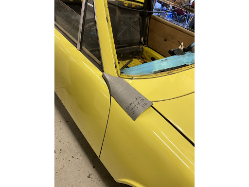
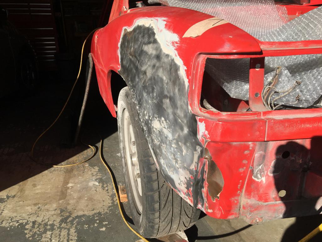
I have already started fixing some of the rust issues and will share that progress in the near future but right now, I wanted to post some of the issues i have on the passenger side front fender.  I have searched and read many of the builds here but I would like some inputs from the people who have gone through this mess.
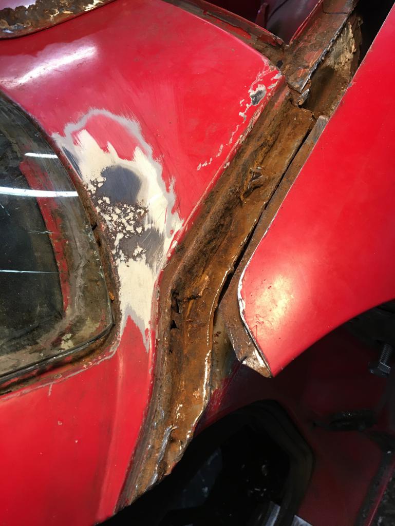
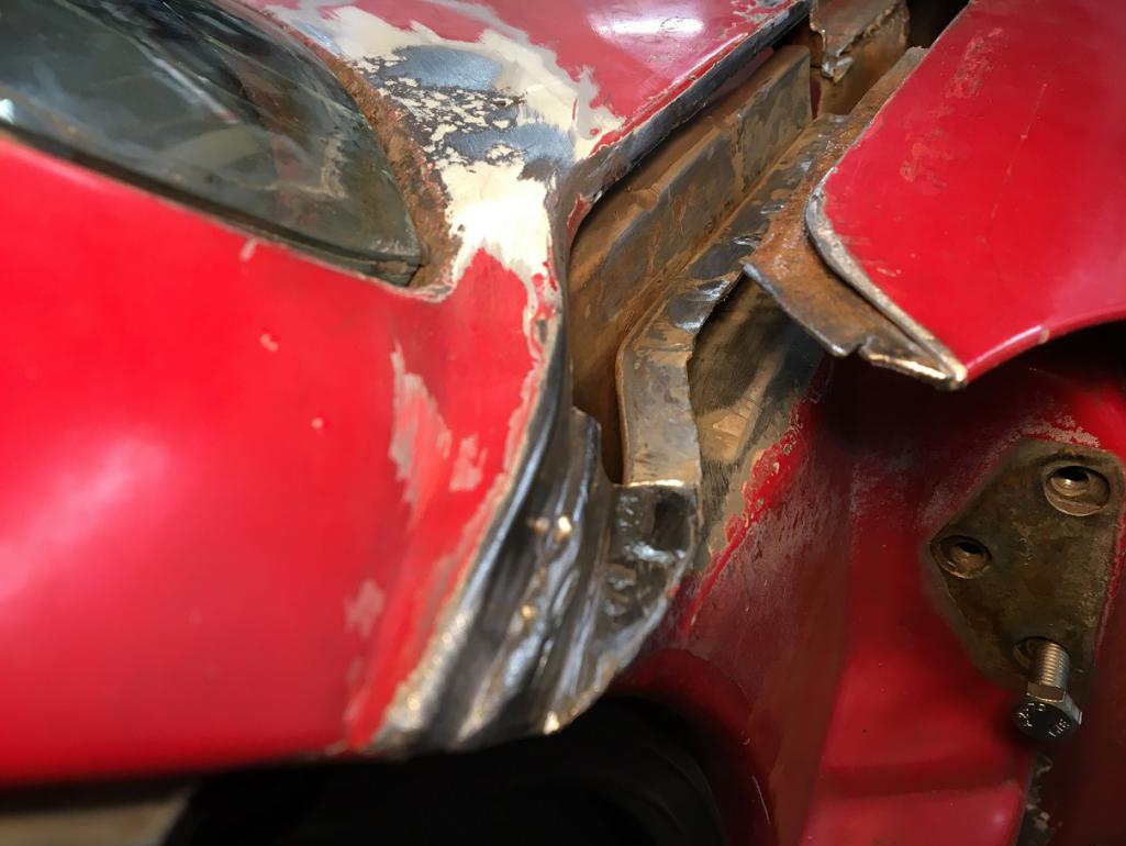
I am trying to understand the construction of the rear part of the fender, more precisely the area joining the front cowling.
Below is a sketch of how I think it is made but i would like someone to confirm... 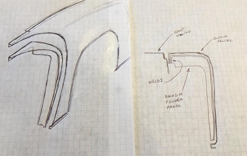
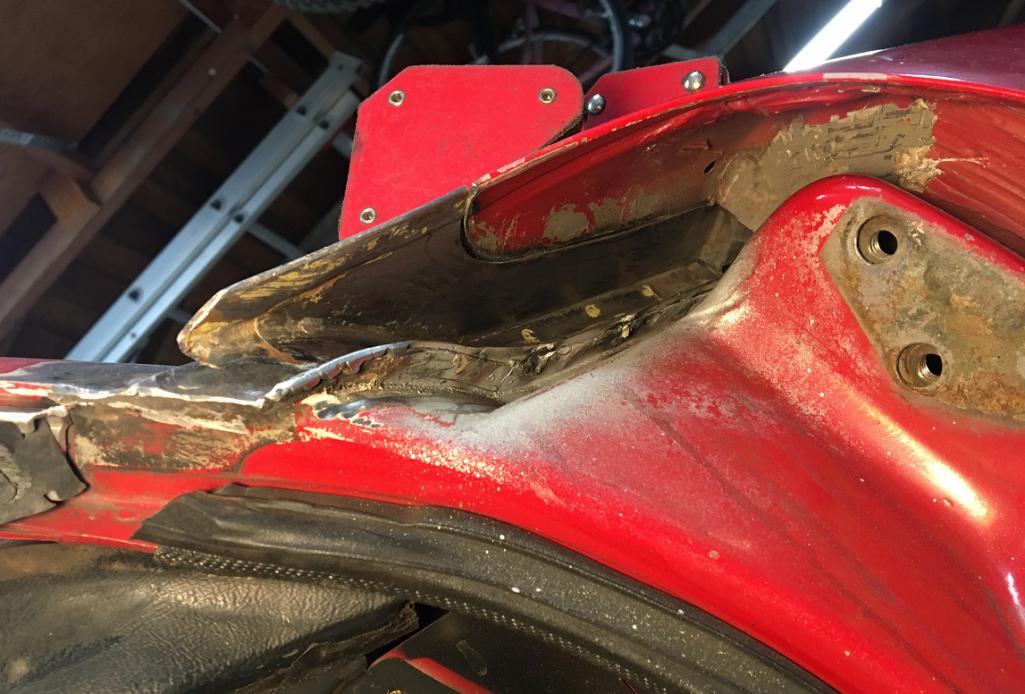
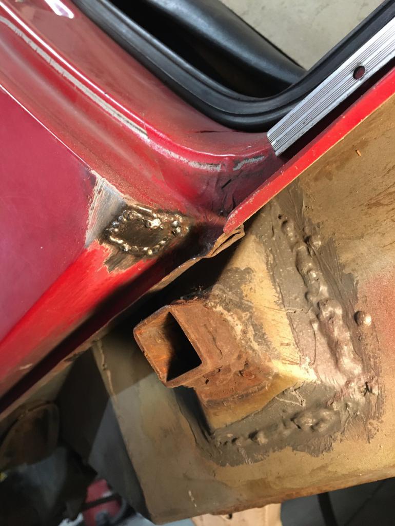
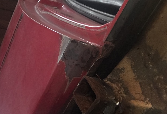
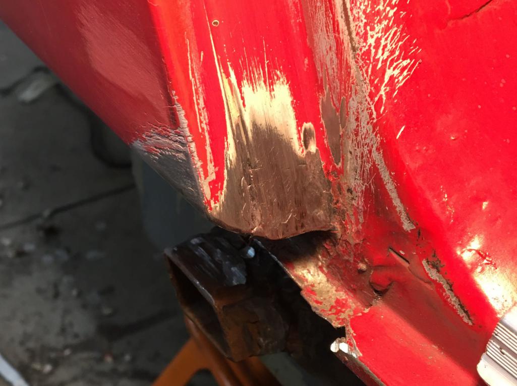
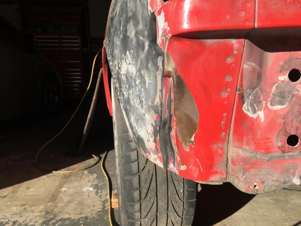
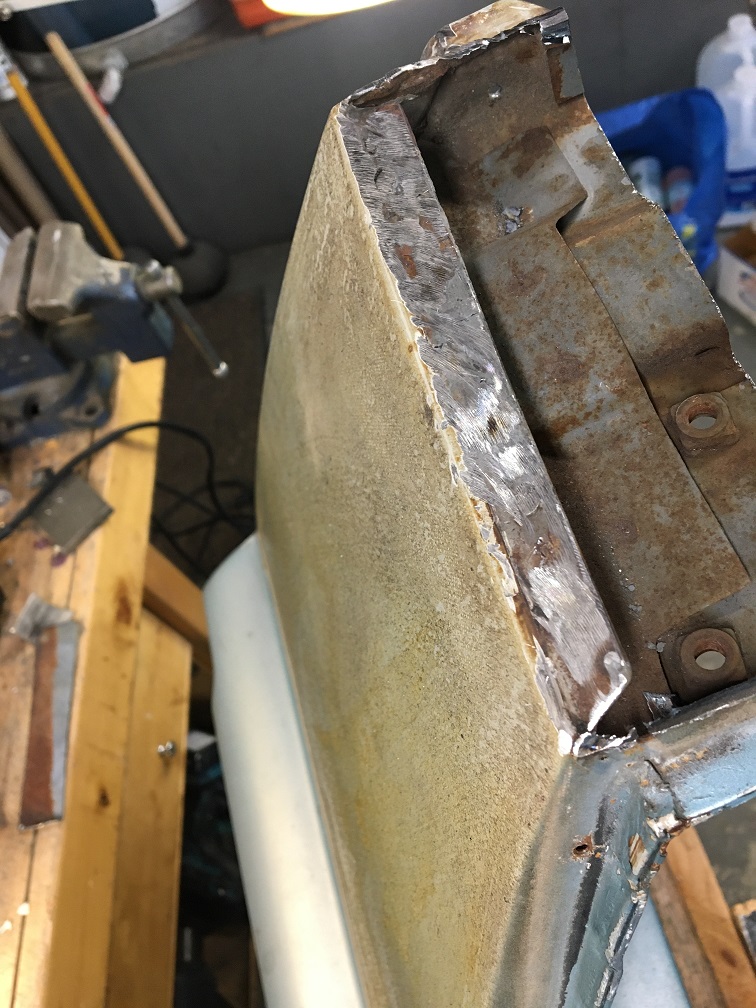
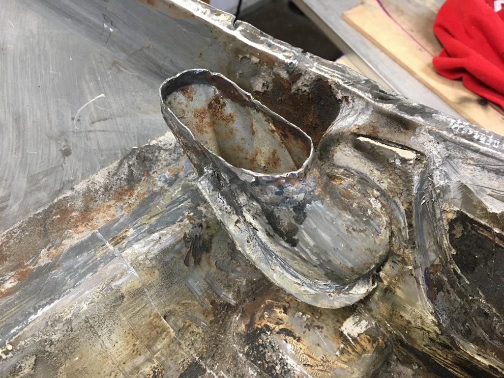
Having removed the seam sealer in the upper rear area, I have discovered "this"  which is not really unusual, but clearly a pain to fix. I am not sure though what I am looking at. If my sketch is correct, I guess the inner rusted layer is from the fender rear bulkhead that actually becomes an inner layer on the rear upper point of the fender by the door and cowling junction.
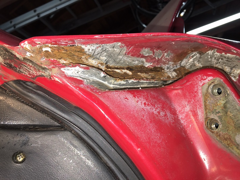
I might be able to cut this from the underside preventing me from cutting the outer surface of the fender. But I would like to better understand what is happening at the junction to the body.
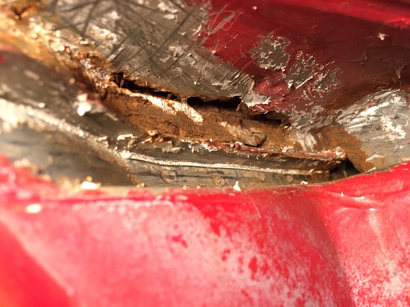
How many layers are there from the fender, one or two?
Is the metal peeling off at the joint to the body the metal from the bulkhead/inner layer, or is it the outer fender layer?
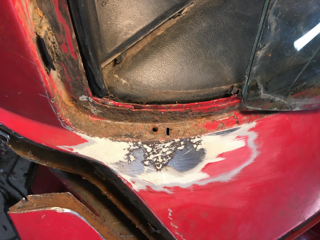
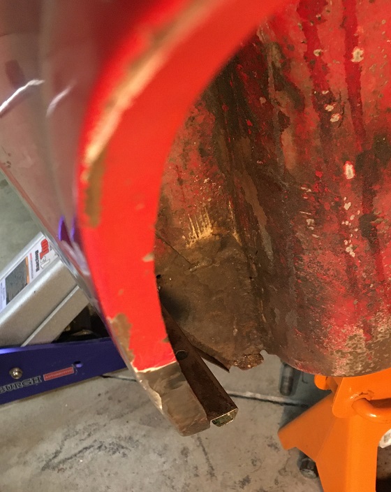
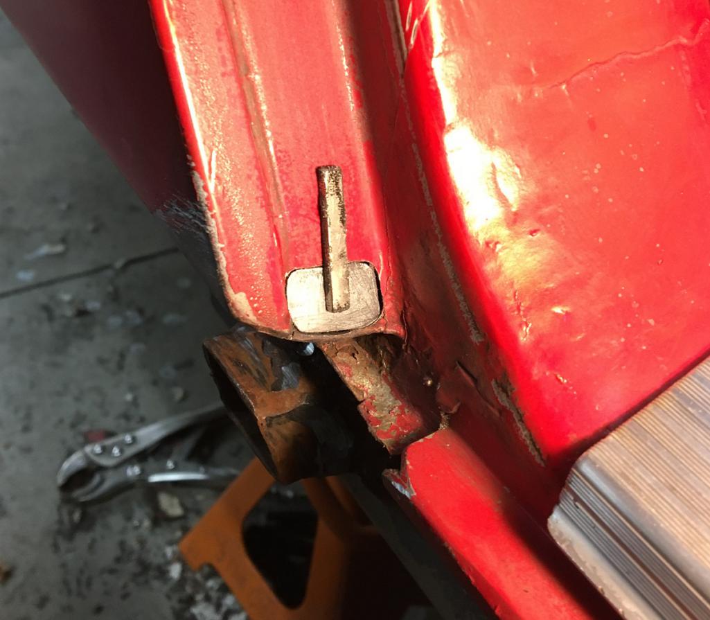
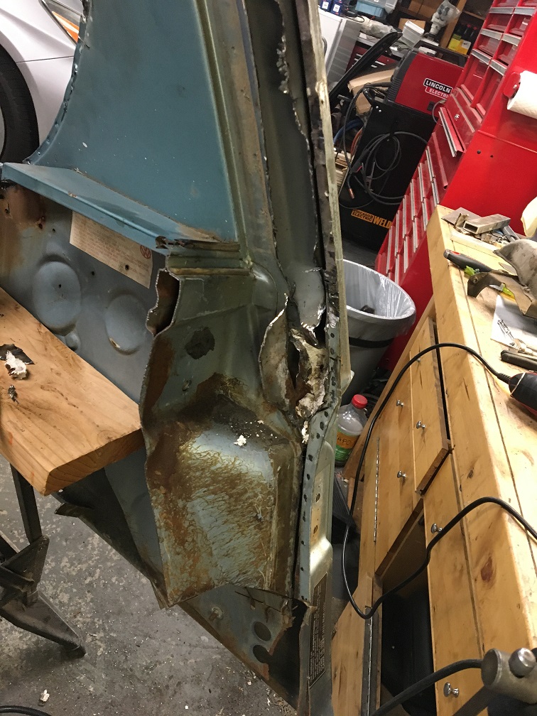
As a reference, this if the situation of the channel, surface rust, but how bad? Is there a way to better know without destroying? Maybe poke with a screwdriver? 
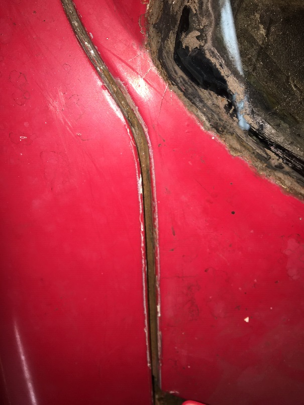
Comments appreciated
Posted by: cary Oct 24 2020, 06:32 PM
You got it.
http://www.914world.com/bbs2/index.php?s=&showtopic=348456&view=findpost&p=2848611
http://www.914world.com/bbs2/index.php?s=&showtopic=249327&view=findpost&p=2550335
http://www.914world.com/bbs2/index.php?s=&showtopic=249327&view=findpost&p=2549481
http://www.914world.com/bbs2/index.php?s=&showtopic=249327&view=findpost&p=2546557
Posted by: horizontally-opposed Oct 24 2020, 06:33 PM
All I can say is…go the distance in that area.
A good metalworker thought he had it—but we had to repaint that side of the car. That was after another good metalworker opened up a window in that spot to "really fix it." Well, there's something going on under the paint again.
It's minor, but we all know what it means… 
If I ever go in there again, I'd really look at not only eradicating all rust with new metal, but what might be done about keeping water out and help find a good drain path for any future moisture that does manage to get into that area.
Posted by: Montreal914 Oct 24 2020, 07:37 PM
@http://www.914world.com/bbs2/index.php?showuser=1608
Thank you for the links, this is very informative. I wish I had a super in law!  This ought to be interesting and definitely challenging.
@http://www.914world.com/bbs2/index.php?showuser=2058
Pete you car has been my inspiration since the first time I saw it parked by the fence at Luftgekült in Long Beach, not knowing it was yours. I was amazed how good the Bahia red could look, compared to my burned and faded one. Immediately after, I inquired here about the nice red car parked by the fence, and found the whole story. It was settled, VW Tornado Red, it was going to be.
Posted by: cary Oct 25 2020, 09:48 AM
I'm going to ask George (AA) and Alex and Pete at RD about making another patch panel. George made the cowl piece, we need the fender section too.
I think I've done 4.
I bought a complete hinge post with fender support and harvested the inner piece. But it would be nice to use new metal. Sitting here thinking if I was to do it again and bought another hinge post I'd take it and have it dipped.
Posted by: Montreal914 Oct 25 2020, 03:37 PM
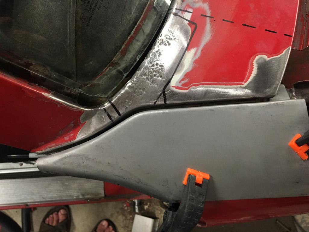
Today's update. After carefully studying Cary's pictures I dove in 
No big surprises here.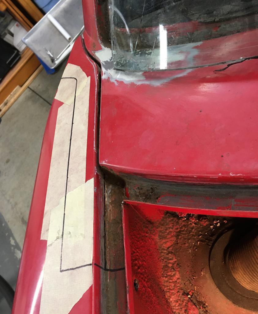
At his point the cowl corner needs to be addressed at the fender junction, at the front trunk seal, and under the windshield area. I think my best bet is to get both or these replacement parts as a foundation for the repair.
Any comments one the fit of these?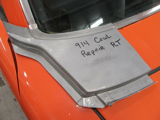
Posted by: cary Oct 25 2020, 04:28 PM
Looks good. Full speed ahead.
I didn't know George even made that piece. Not in Body Sheet Metal section.
I'll do some digging. Lionel has it in their Ebay store.
Posted by: Montreal914 Oct 25 2020, 04:34 PM
On AA website:
Part number: 91450303211A and 914503057R
Question is should I put a few patches taken from the repair piece or cut a lot of the car to fit the repair piece as a whole... 
There is still a lot of good metal on the car in that area. I fear going into the A pillar.
Posted by: cary Oct 25 2020, 05:17 PM
Only cut out what you need too on either piece .............
Next big issue is making sure you have the correct gap between the 2 pieces, so the cowl trim strip fits correctly. On Doug's I had about 10mm ( don't know where that came from, we were about 1mm too tight ) that was too tight.
But we made our own pieces by hand.
http://www.autoatlanta.com/results.php?partnumber2=cowl%20repair&narrowcar=914%201970-76
Only one piece correctly categorized. I'm going to buy one of each of the fender portions. Already have a pair of the cowl sections.
Posted by: Montreal914 Oct 25 2020, 06:10 PM
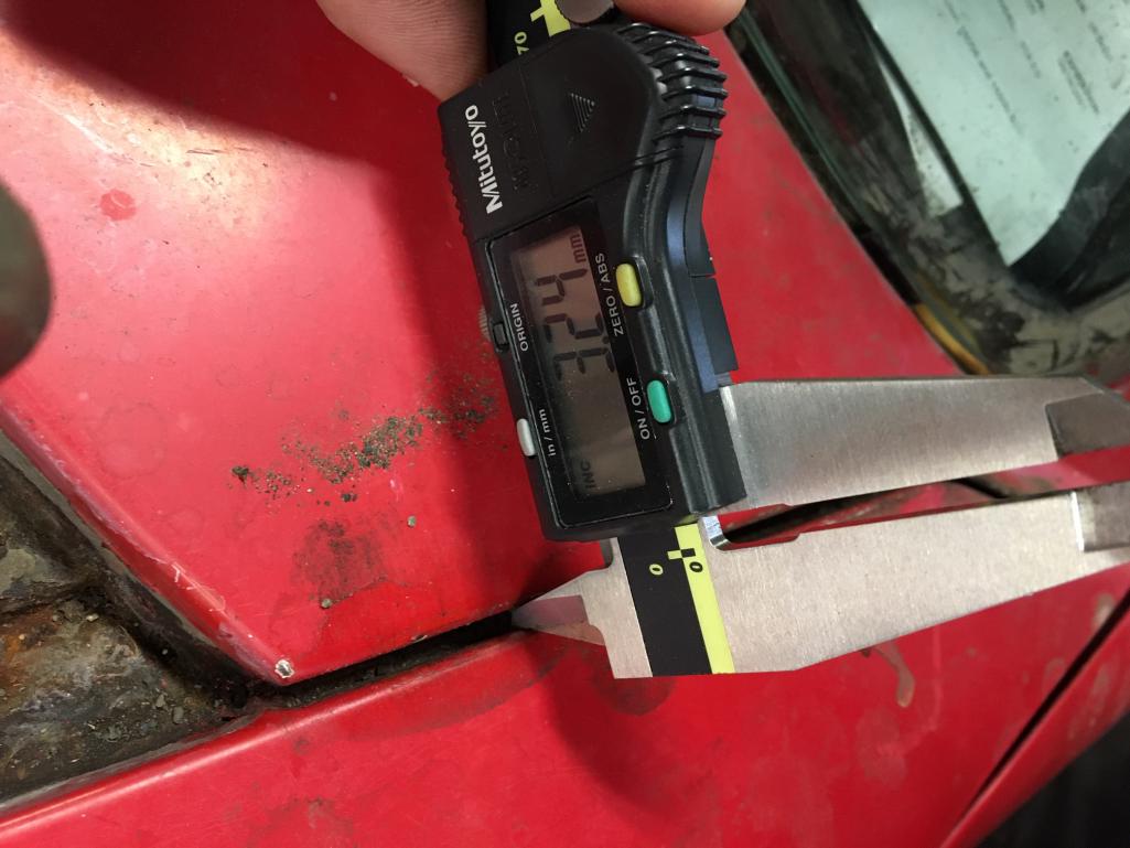
Yes, it's all about the gap and its evenness throughout its whole length. From the driver's side, it looks like ~3.2mm, which happens to be spot on 1/8" flats.
Will contact AA tomorrow and place an order.
Thank you, will cut only the bad stuff and patch using what is required from new panels. 
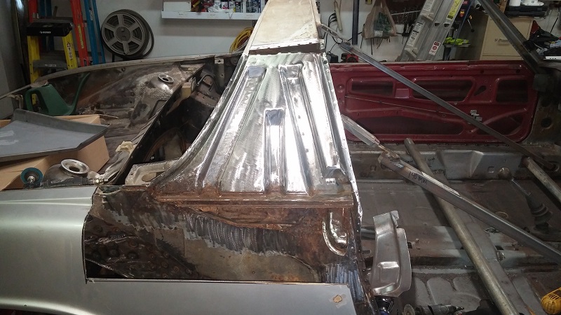
Posted by: Montreal914 Oct 27 2020, 07:32 PM
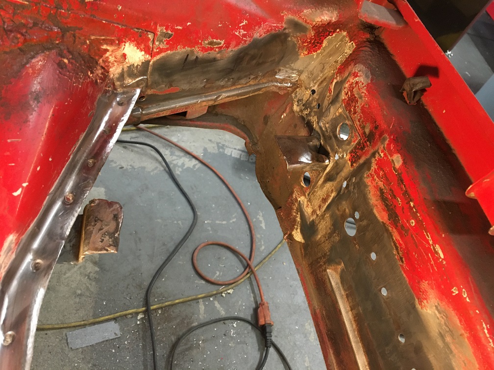
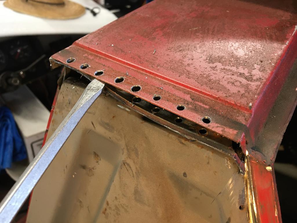
I worked a couple of hours last night and began to look for solid metal at the junction of the fender with the cowl.
This is after a cut below the fold of the cowl. If I need to go above it I will, but I would rather weld-in the new piece in this hidden area.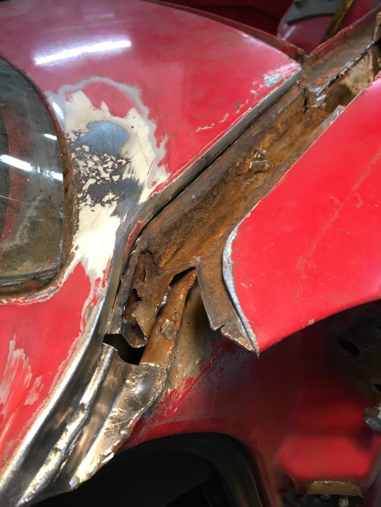
After the rusted metal was removed, I now have a decent shelf for the new piece to rest on and a nice clean metal in the vertical section of the cowl joint to the fender. Obviously, there will be more prepping before reconstruction.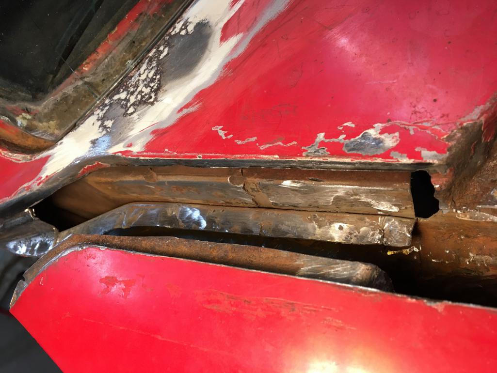
Posted by: Montreal914 Oct 27 2020, 10:33 PM
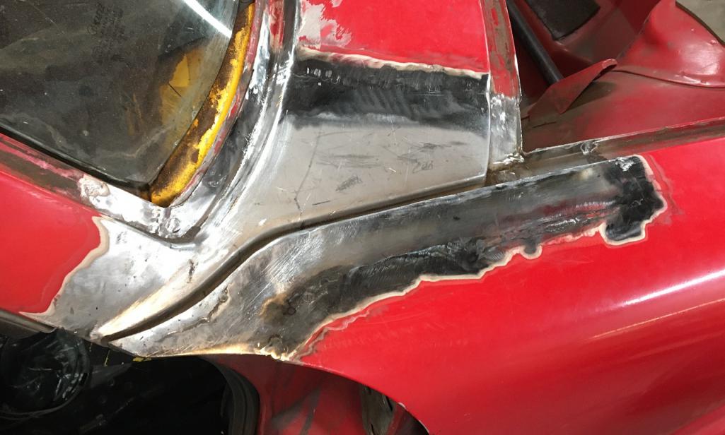
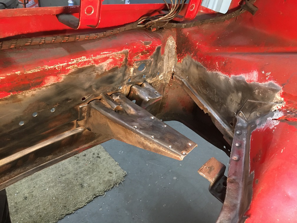
A little more cleaning up tonight. Looking at the situation I am considering 2 options but which one would be the best...
@http://www.914world.com/bbs2/index.php?showuser=1608 I really value your advice. What would you recommend? Cutting across per dashed line, or a patch work?
For the patching option, the trunk seal area would get cut out the same way as the fender to cowl to hide the weld. In the windshield area I have to go on the finished surface , unless I Ospho the surface and do the cut in an area where the windshield trim will hide the welds, but that seems like a half job since I am already way deep in this.
Comments appreciated 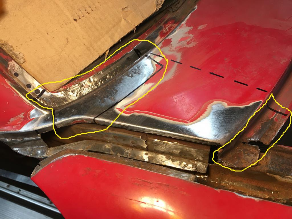

Posted by: Arno914 Oct 28 2020, 03:03 AM
Hi,
here are pics of a NOS Fender I aquired a long time ago. Maybe that helps to understand the construction.
Greetings, Arno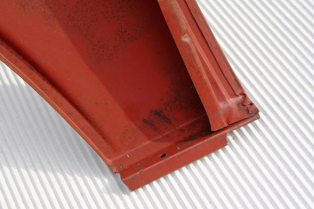
Posted by: cary Oct 28 2020, 08:26 AM
I'd wait till you have the new patch panel in hand. To verify mold and size.
I'd take the section that attaches to the windshield frame out with a couple more cuts.
That way you can lightly touch the spot welds on the glass channel with the right angle die grinder and peel them back.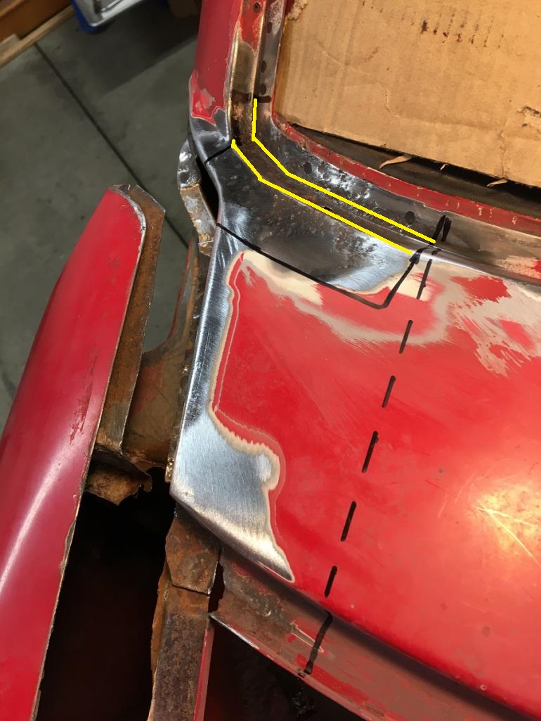
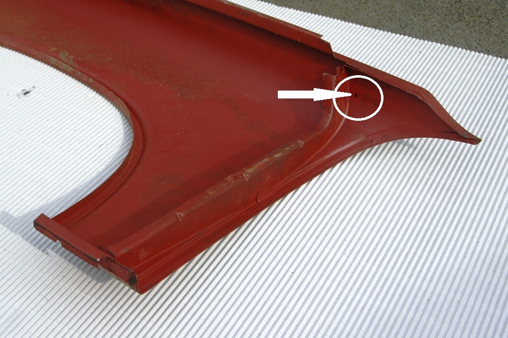
Posted by: Arno914 Oct 28 2020, 08:47 AM
Thanks to the detailed pics from Montreal914 I noticed that little hole underneath the fender. Looks like an ideal access for rustproofing the otherwise not reachable area between the fender walls.
I will give this area a good treatment with "Fluid Film". 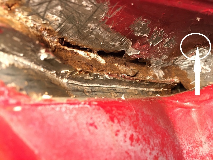
Posted by: Montreal914 Oct 28 2020, 09:29 AM
@http://www.914world.com/bbs2/index.php?showuser=1608 ; Thank you for the input, that second cut will definitely help the removal of these spot welds on the windshield frame I am looking forward receiving the sheet metal to compare with the original. What I don't like about the cross cutting of the cowl (dashed line) is that I will loose many references. The little fold that I have left out by cutting below the finished surface still keeps things located.
@http://www.914world.com/bbs2/index.php?showuser=24260 ; Thank you for sharing the pictures of that beautiful fender. Yes, this will be of great help on the details, especially since there is no seam sealer anywhere.  I do have to tackle the bottom end of it too...
  but one nightmare at a time. I have very limited experience in this type of work, but luckily, the help on this forum is simply the best.
Posted by: Montreal914 Nov 1 2020, 08:04 PM
Did a little work this WE. I removed some metal in the windshield corner area while waiting for the repair sheet metal that should arrive Wednesday. I still haven't removed the pitted area, but I am leaning towards cutting the solid marker line, not the dashed one in hope to better keep the overall line of the cowl.
We can see the factory reinforcement layer in the windshield frame corner. I didn't touch that piece, the cut is factory.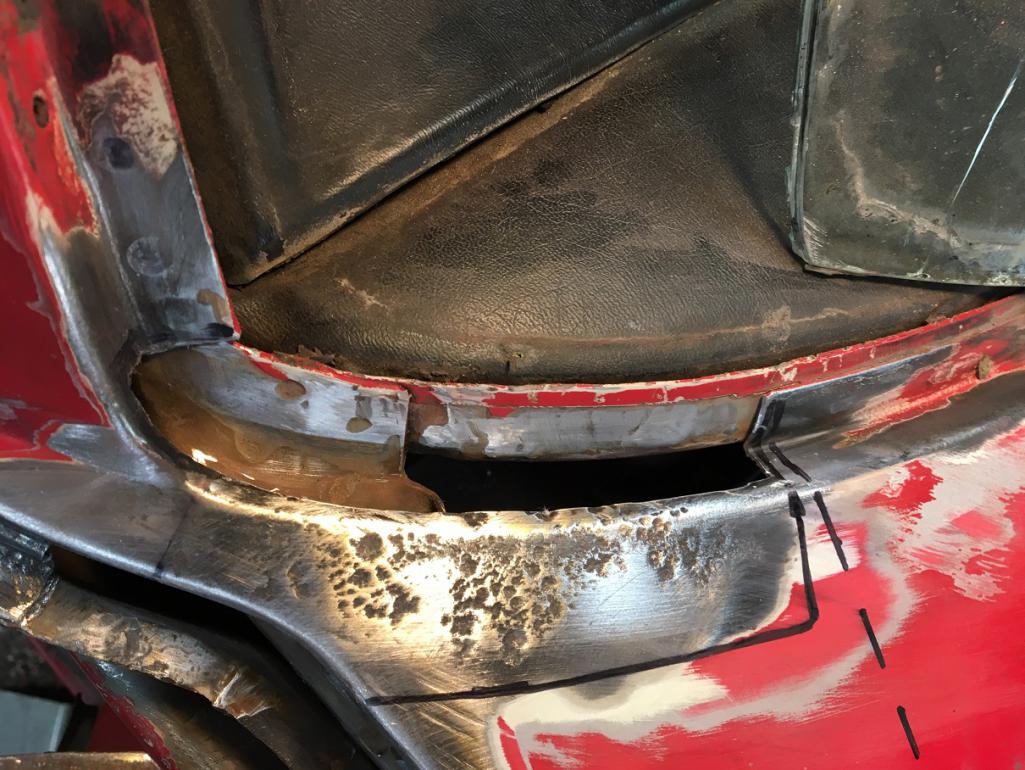
Then I removed the rusted metal in the cowl corner to the trunk seal area. This is basically ready to receive the repair sheet metal piece after some Ospho and protection.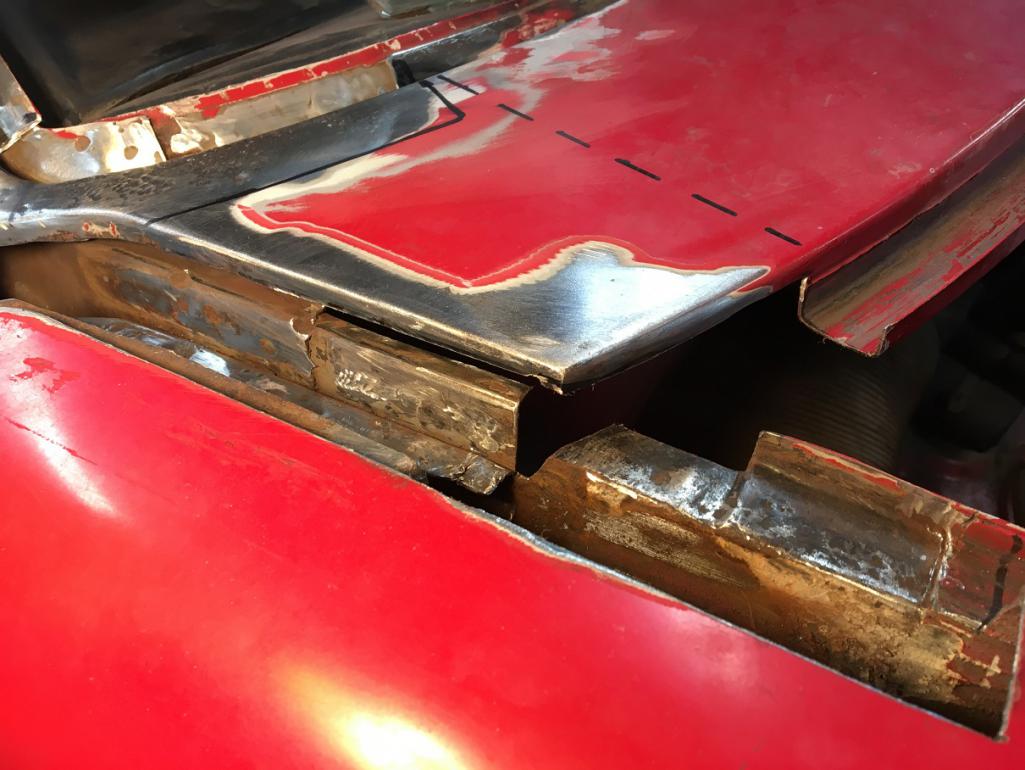
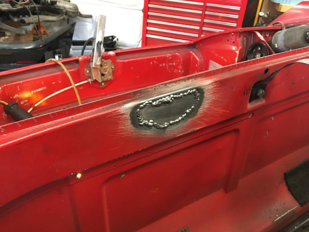
I moved on to repair some DAPO chassis weakening done to run the wiring to a very important piece of equipment , an amplifier mounted on the bulkhead in front of the tank...
Before;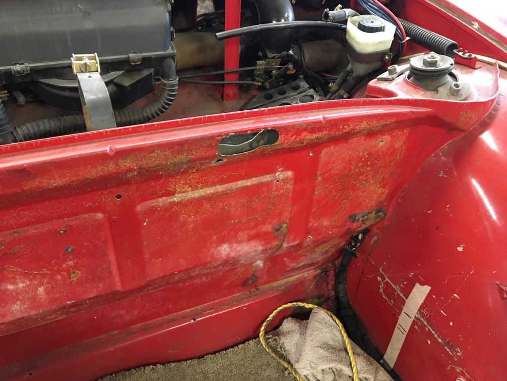
Prepared the patches to fit in the 2 holes, file, adjust, try, and again, until good fit...
The bulkhead is actually thin metal ~0.030" while the back side of that beam is closer to 16 ga. Luckily, I had pieces of metal of the same thicknesses.
Bulkhead layer patched: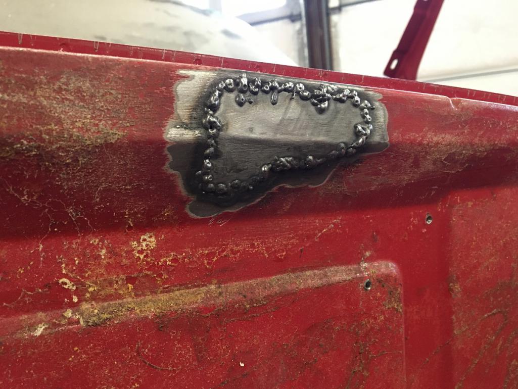
Then the back side (tank side) of the cross beam piece.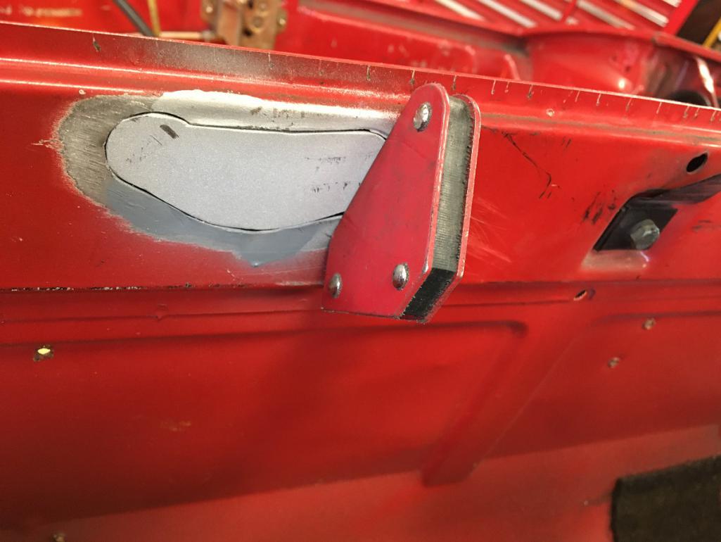
Small steps...
Posted by: Montreal914 Nov 6 2020, 12:50 AM
Yesterday I received my sheet metal repair pieces, the cowl and rear top fender parts.
The cowl piece is pretty nice and I am still wondering what should be my best approach with this. I can keep as much original metal to the car and cut all up the repair panel to patch the various areas, Or cut straight across the car's cowl and install about half of the width of the repair piece.
Here are a few pictures of the cowl piece.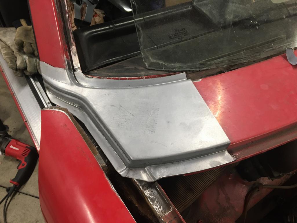
Here we can see that hey could have been more generous on the front fold for the trunk seal. I will need to extend that lip a little.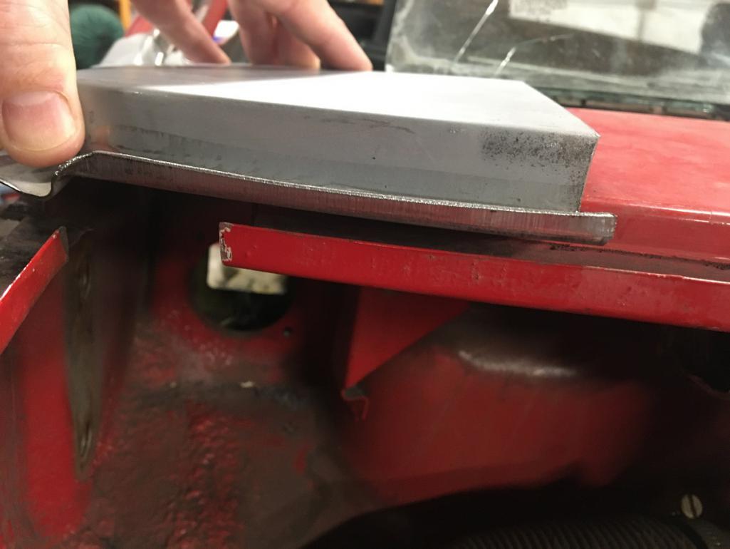
Last one showing the line where I could cut the new piece to repair the damaged sections of the car, otherwise, just use the left (car orientation) half of the repair piece and cut the car up.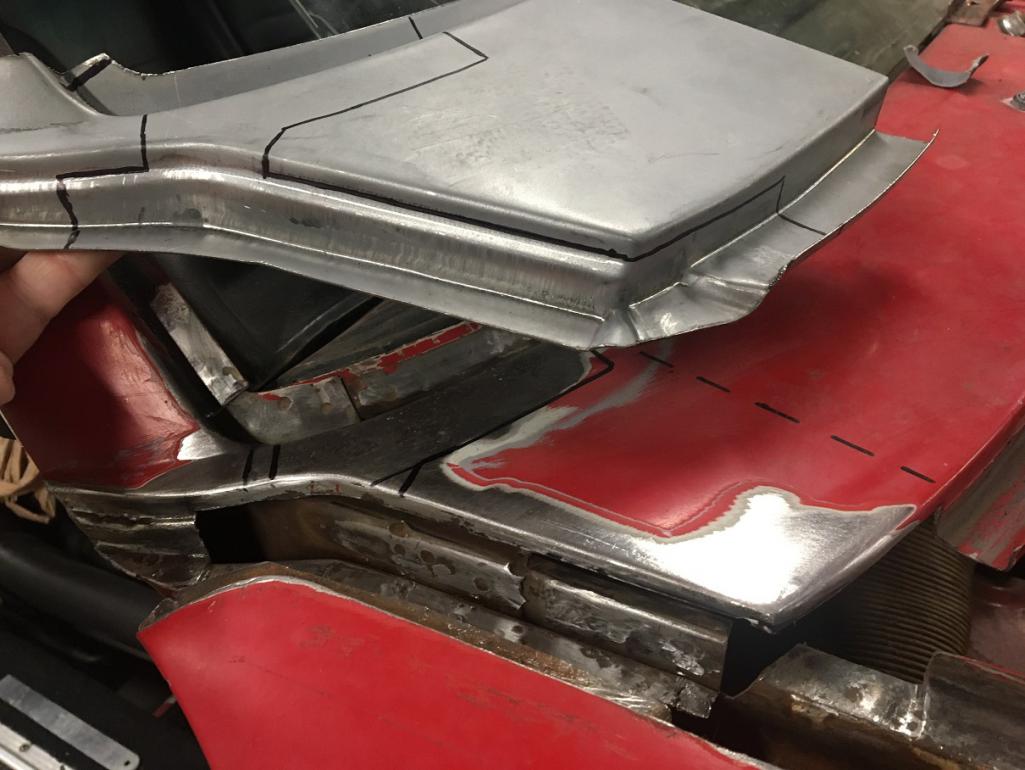
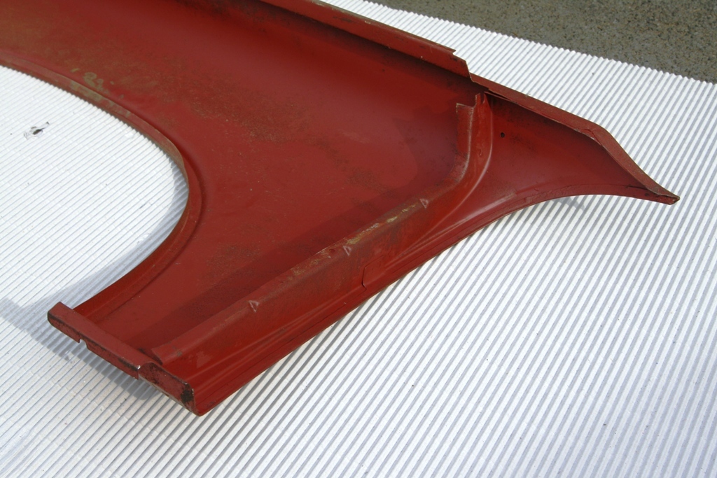
Moving on to the fender repair panel. This one is made for Auto Atlanta but is not the same quality as the cowl piece. The part was bent of hit or something as you can see. Also, the curved outside edge that will create the door gap is not folded. This will be a challenge (at least for me) to fold while creating the proper curve that will define the front top door gap.
Definitely open to suggestions here...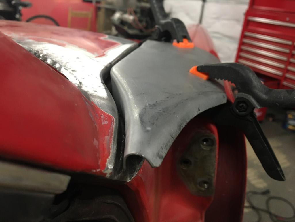
In this angle you can see the damaged area of the part which lifts up the back side of it... 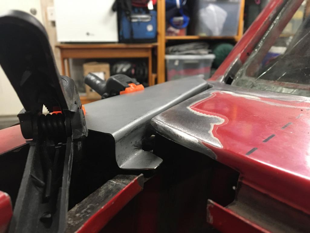
I would like to tackle the cowl repair this weekend, but before that, I need to decide how.
Open to comments/suggestions. Thanks!
Posted by: cary Nov 6 2020, 12:08 PM
Your now into what we/I call the art of massaging patch panels. Almost all need
tuning.
Give us a shot of the fender patch flipped over.
Posted by: horizontally-opposed Nov 6 2020, 12:16 PM

Hi,
here are pics of a NOS Fender I aquired a long time ago. Maybe that helps to understand the construction.
Greetings, Arno
It sure does—to the point I am pretty sure I know what the problem with my fender was, and maybe still is, now.
Posted by: Montreal914 Nov 6 2020, 03:23 PM
@http://www.914world.com/bbs2/index.php?showuser=1608
Here are a few pictures of the fender patch underside. 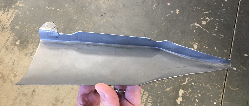
Here we can see the dent, near us to the left 1/3 in the picture, causing the back end to lift up. I don't think the 2/3 area is dented, just the fold creating this shadow. 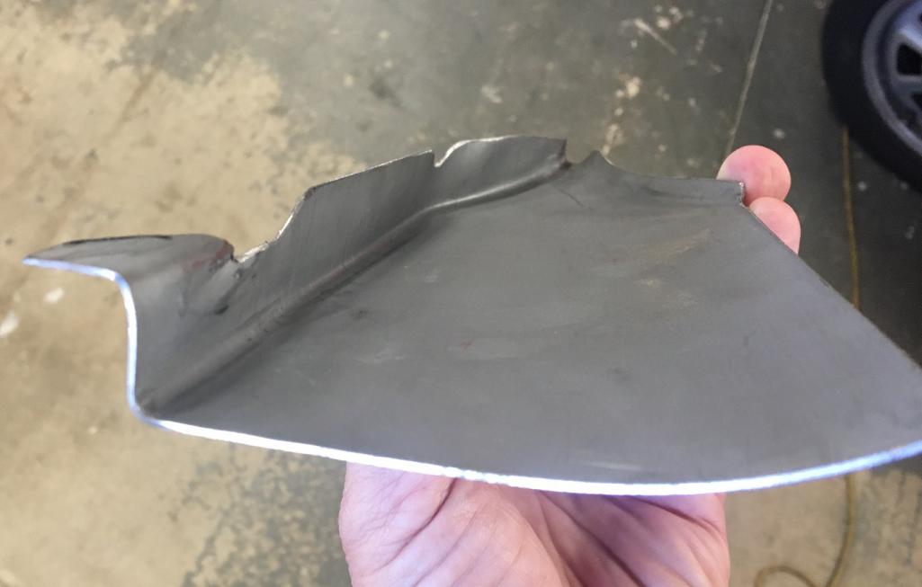
The lines are pretty good when looking a the original piece I removed from the car. Just wished they had folded the door gap edge...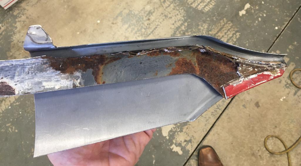
Any final recommendations on the cowl piece? Either I cut across, which minimizes the amount of welding, but there is a risk of trunk line "breakage", or I replace only what is damaged on the car which keeps both the trunk line and the cowl to fender line as i would be welding the new material to unexposed surfaces. Then again, I do need to replace some of the top surface in front of the windshield frame creating a weld parallel to the windshield on the finished surface. Maybe this will cause a lot of distortion...
I am ready to go, just need a little hint  All suggestions welcome
Posted by: cary Nov 6 2020, 03:49 PM
I'd say do the cowl section first.
Then tune the new fender portion to the new cowl.
As for the new fender section you'll need to create some dolly strips to tune/reshape the tip.
Posted by: Montreal914 Nov 6 2020, 04:08 PM
I'd say do the cowl section first.
Then tune the new fender portion to the new cowl.
As for the new fender section you'll need to create some dolly strips to tune/reshape the tip.
Yes, cowl first, agreed.
Would you cut across from the windshield frame to the trunk, or do a patch work keeping as much of the original metal.
This is my main hold up right now. Cutting the new piece per my marker lines with multiple welds or just replace a big surface using the left half of the new cowl piece?
Posted by: cary Nov 6 2020, 04:24 PM
Go big. You wouldn't be happy welding that short flange to the step. It would explode.
Anywhere the material gets shaped/stretched it doesn't like too much heat.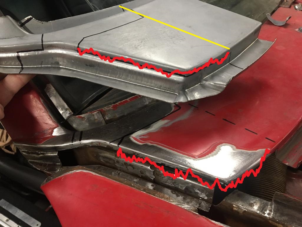
Posted by: Montreal914 Nov 6 2020, 04:33 PM
Go big. You wouldn't be happy welding that short flange to the step. It would explode.
Anywhere the material gets shaped/stretched it doesn't like too much heat.
Perfect!
Go big or go home as they say.
Will cut the cowl up across and use the new piece. Thank you for the input.
Next posting will be of this accomplishment...

Posted by: Eric_Shea Nov 7 2020, 08:05 AM
If you leaf through this album, there's a ton of cowl repair pics. Hope that helps:
https://www.facebook.com/media/set/?set=a.10156365705328193&type=3
E.
Posted by: Montreal914 Nov 15 2020, 11:33 AM
@http://www.914world.com/bbs2/index.php?showuser=1110 Thank you for the link. Very nice pictures and, as expected, beautiful restoration work!
Time for a little update at my end. Before installing the new cowl repair piece I had to take care of the rusted corner in the inner fender area. I created a little patch that had many corner and struggled with very limited access to install it. Not the best work, but it will have to do... Then I prepped the area with weld through primer.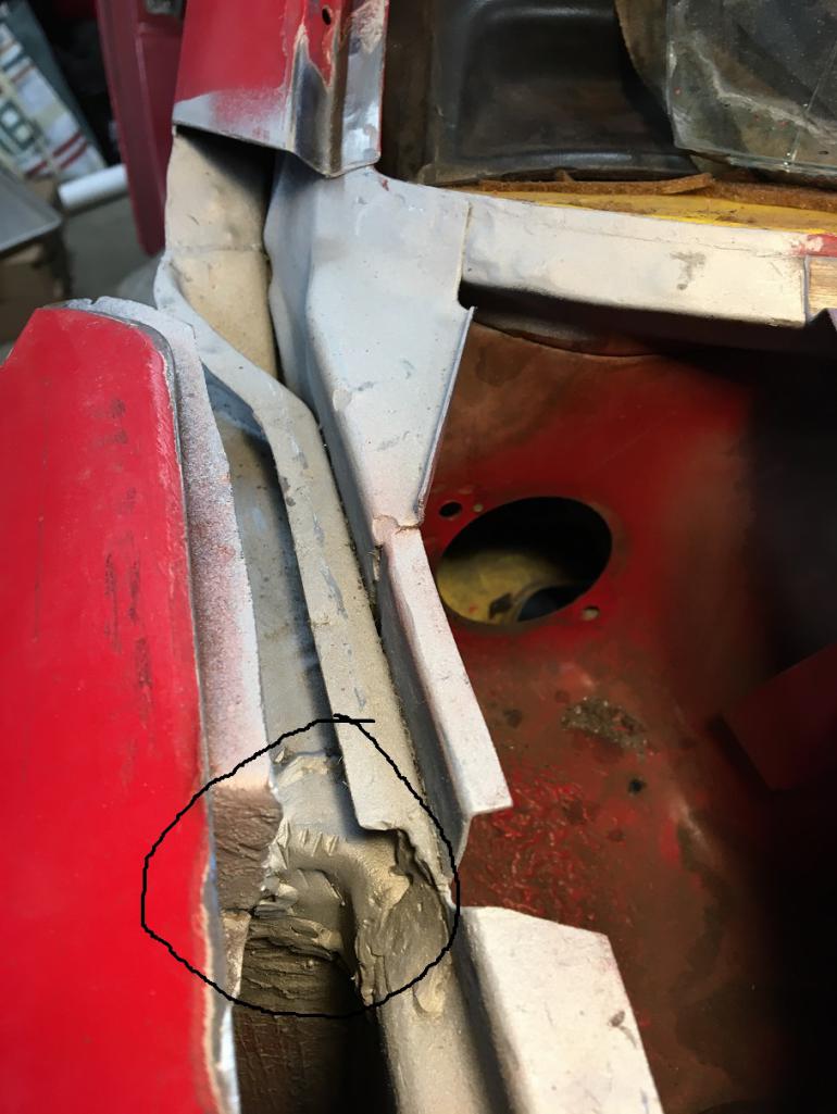
Repair piece ready for install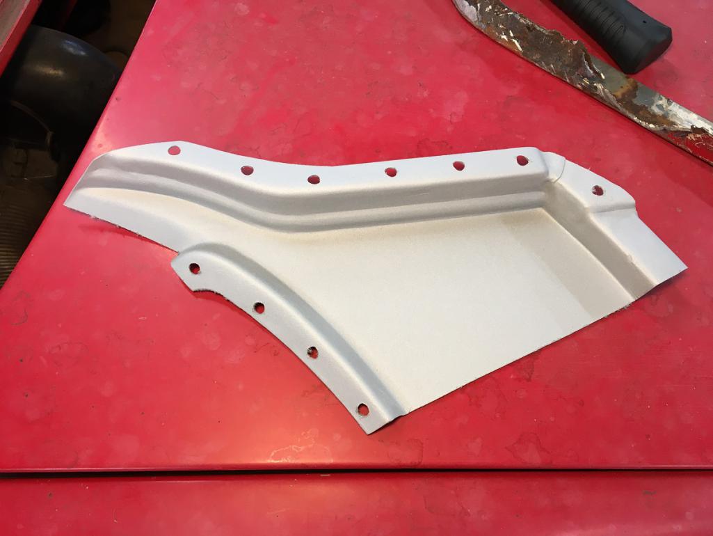
After a lot of trial fit and subtle grinding and filing of both the car and the repair piece, it was time to make the big step of installing the cowl repair piece. After a couple of tacks at the windshield area, I wanted to fit the trunk seal area.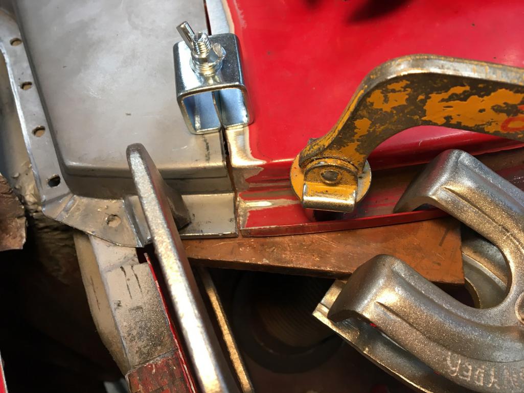
Then checked the result from underneath and wasn't happy with how this was lining up... Time to cut and redo that.
Original attempt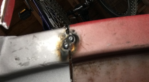
Second try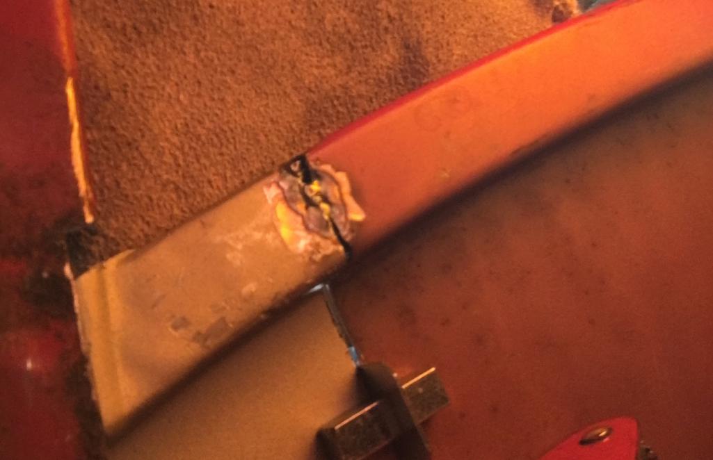
Moving on to more tack welding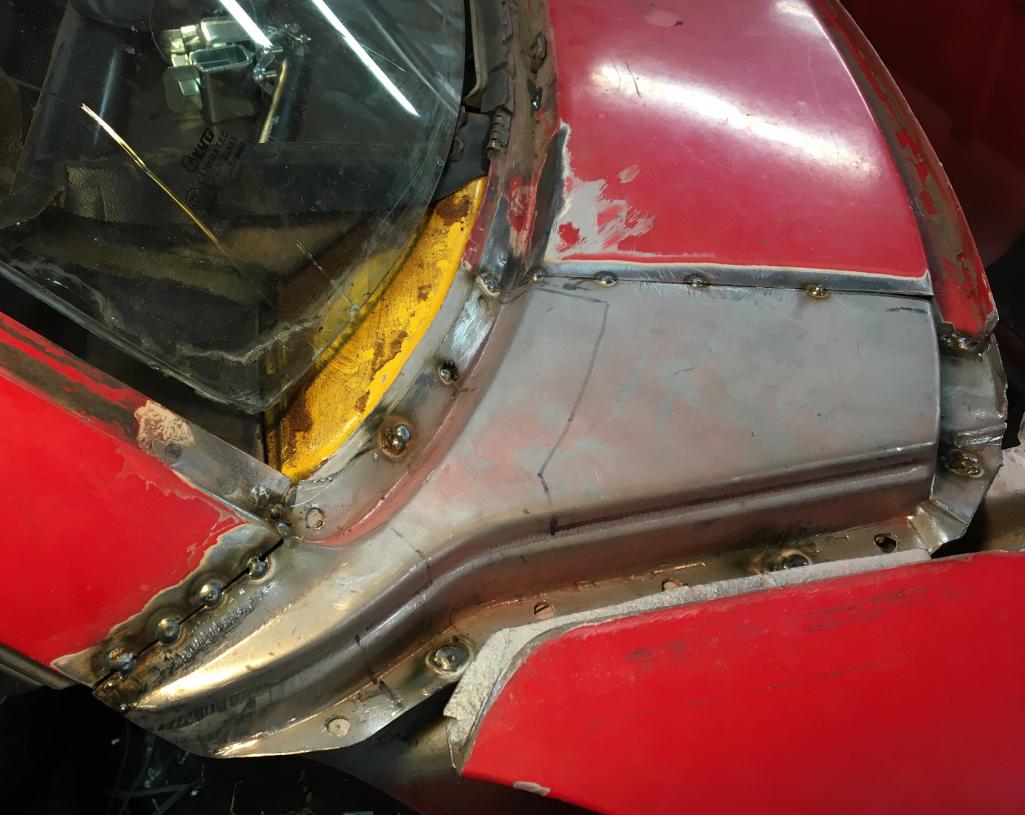
Making sure things are still lined up. Not perfect but I didn't think I had the ability to do better.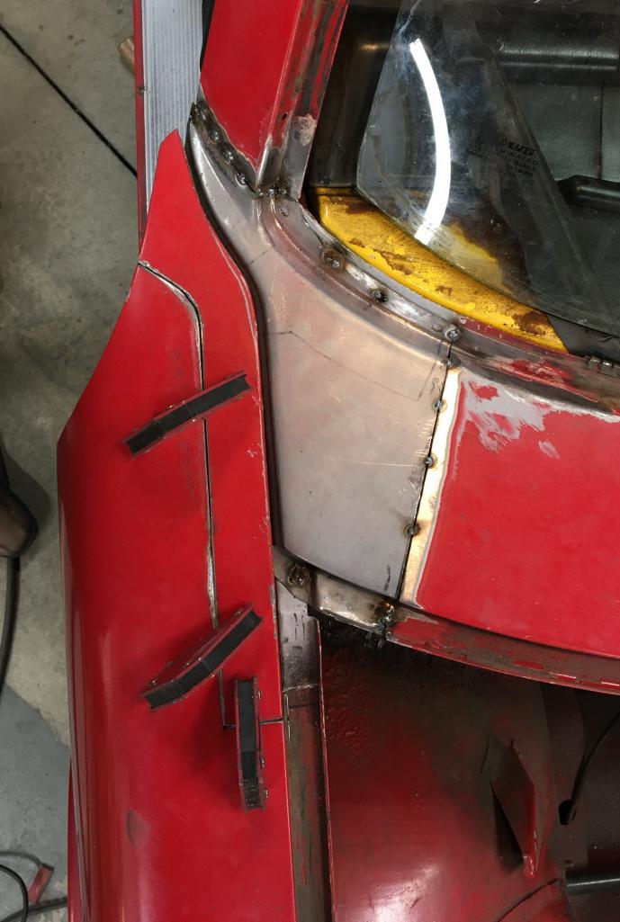
The front edge was a concern and this is where we can see that the reproduction part is not 100% perfect. I was able to raised it up with light taping from underneath but final body work will need to address that area.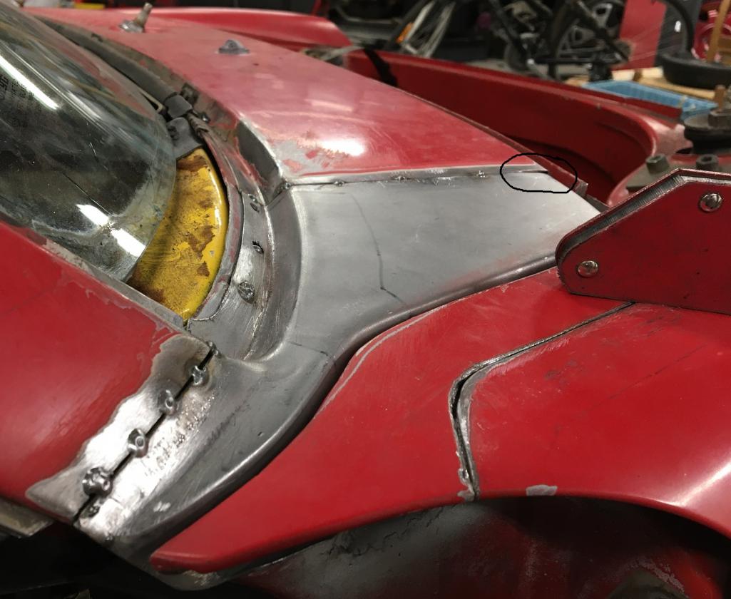
Then, slowly fill the voids between the tack weld, one spot at a time...
Still have the back edge of the A pillar to complete but this is close to final. As a first attempt to venture into this kind of work I am happy with my accomplishment. Support here was key @http://www.914world.com/bbs2/index.php?showuser=1608 . Hopefully the second part of this repair, fender side, will go well too.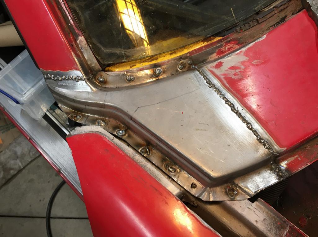
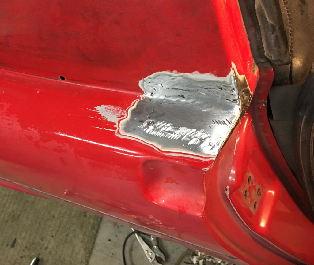
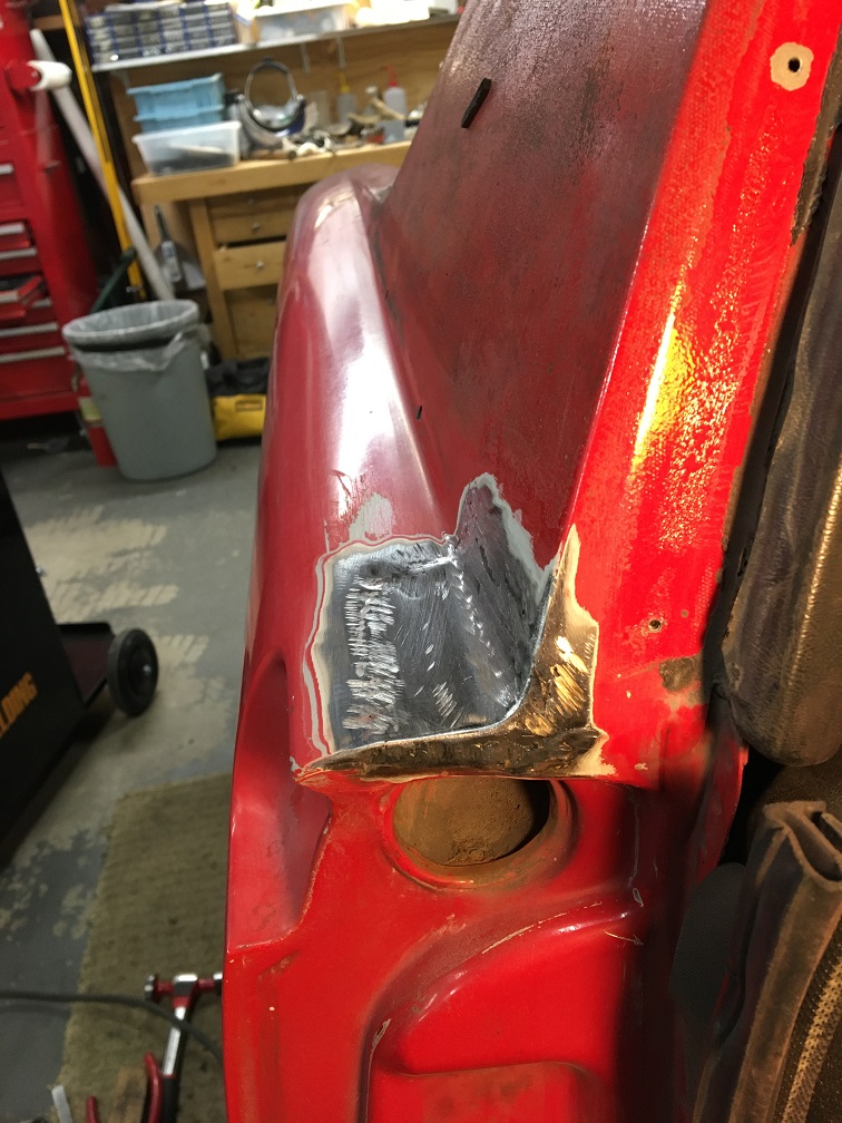
Posted by: Montreal914 Jan 24 2021, 05:42 PM
It has been over two months since I posted some progress, time for some update. Things have been moving along pretty well.
The welds of the cowl piece were grinded down and now ready to move on the fender rebuild.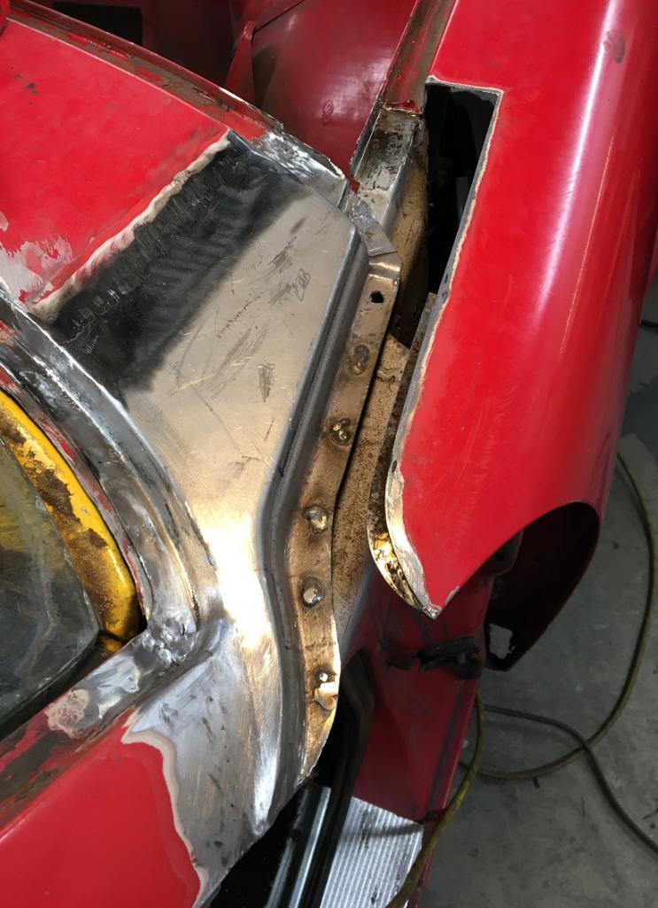
The more I was looking at the AA top repair panel, the less I was attracted to use it. So I decided to hunt for and original front fender upper corner that I could use as a whole, both the inner and outer portion. I was lucky to find this one in decent shape that I started dismantling and preparing. 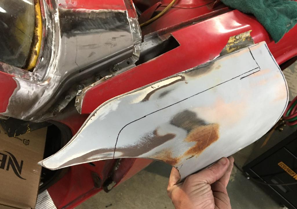
The back side is very good looking on the recycled piece especially compared to the original portion next to it... 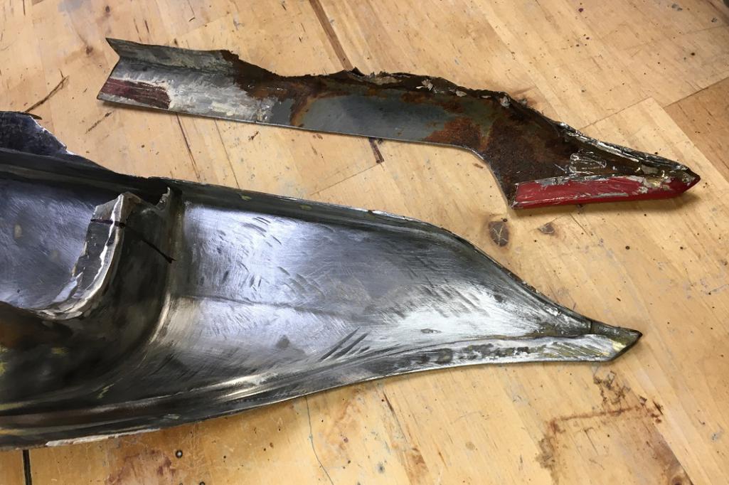
Now, it needed to be cut down to fit on the car. It was also missing a portion of the trunk seal channel, so a little more fabrication and obviously a lot of back and forth to make sure everything fits perfectly. 
Making progress...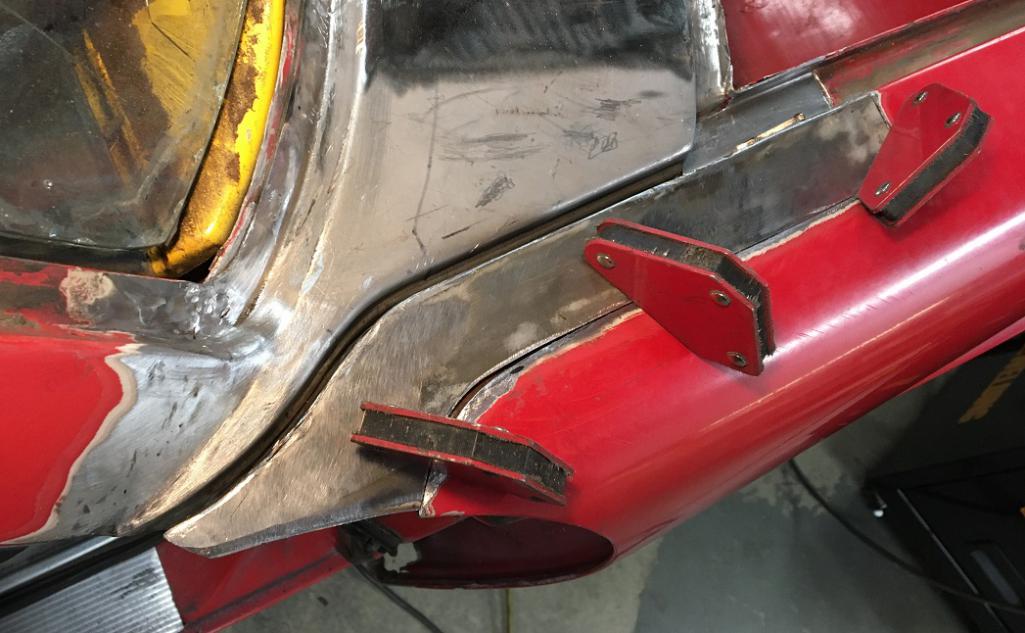
And, once ready, tack welding, making sure the alignment is good.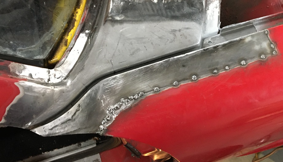
Since there was a little step at the door front edge line, I added some metal and refinished the line accordingly.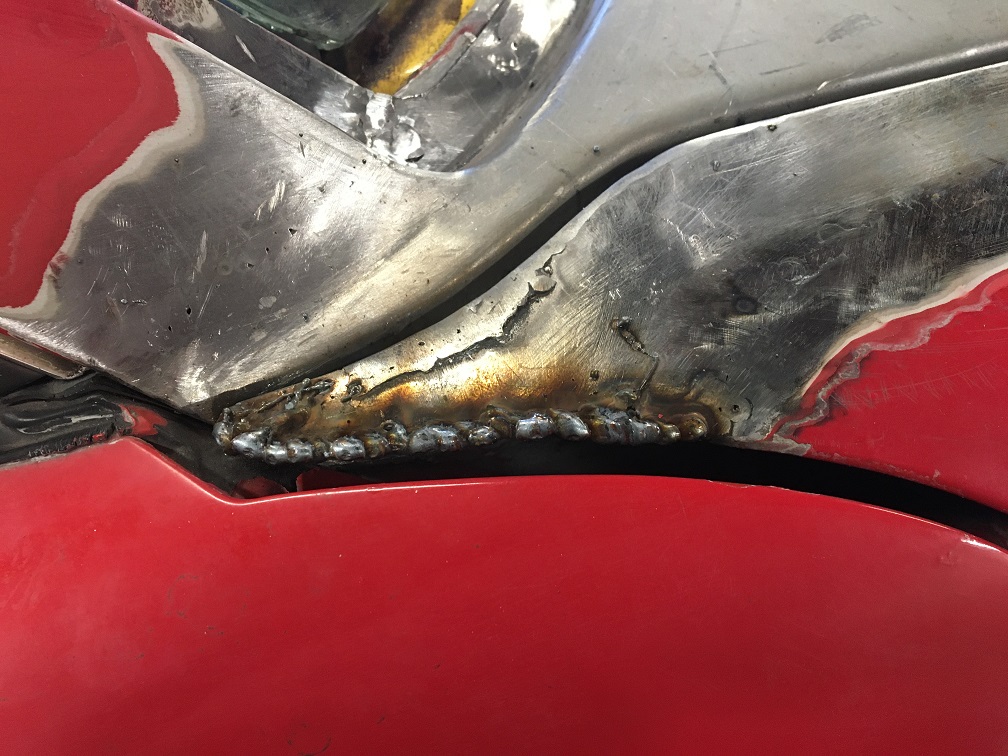
And the end result 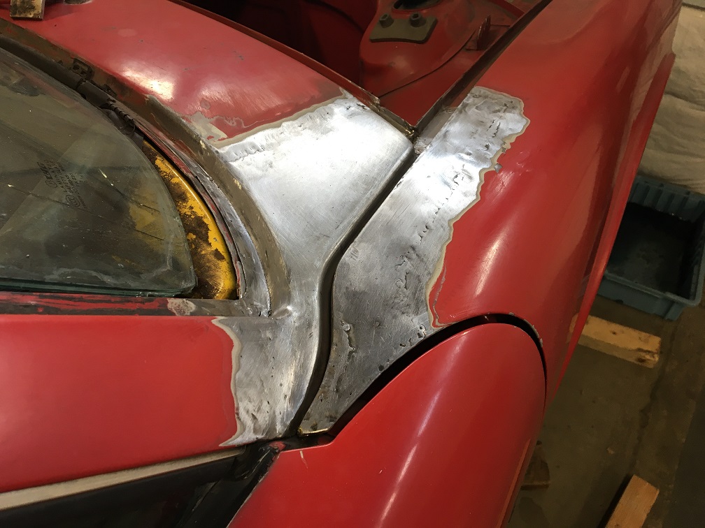
Posted by: mb911 Jan 24 2021, 06:01 PM
Looks great. That is a spot on my car I repaired and ended up with a bit to much gap.. kinda sucks as the car is all painted now. I wanted to find wider welting to fill the gap..
Posted by: Montreal914 Jan 24 2021, 06:04 PM
Moving on to the other problem area of this fender...
The typical rusted lower point which is located near the doubled up packed with seam sealer, not very surprising...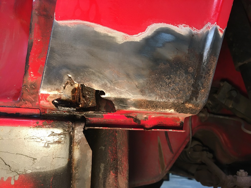
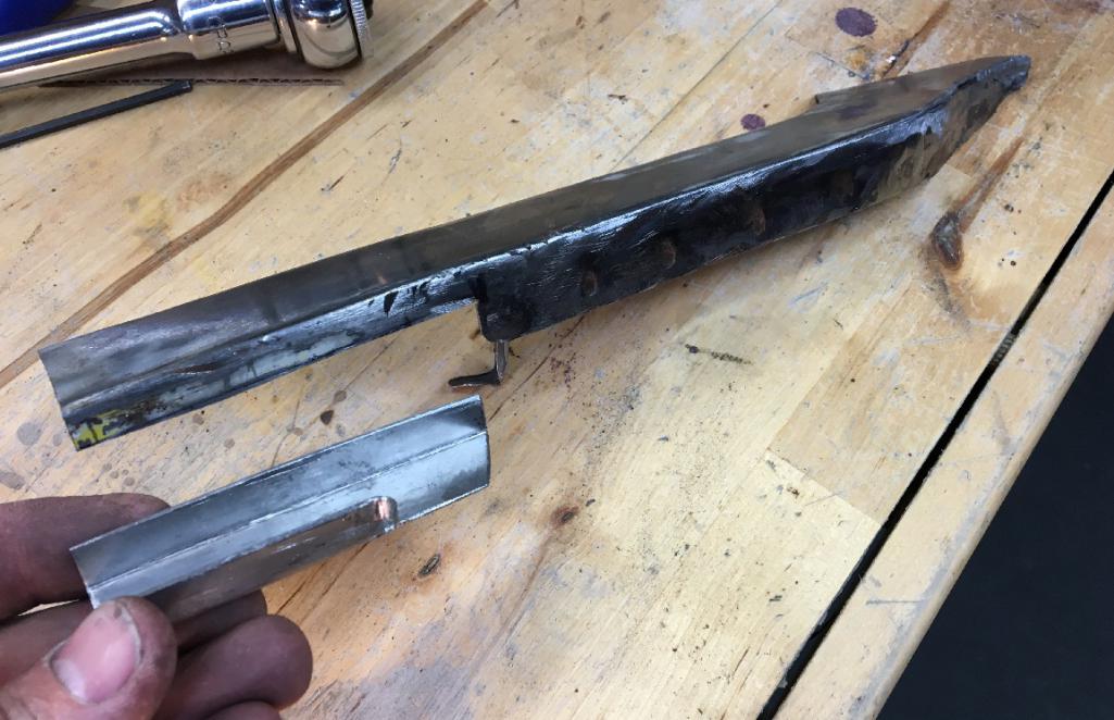
Again, AA sells a repair piece but I prefer using an original piece and got this one 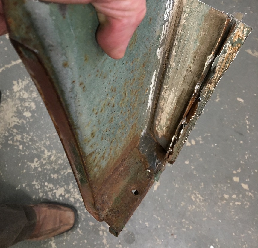
After removing all of the unnecessary metal and seam sealer, the parts started to look a lot better.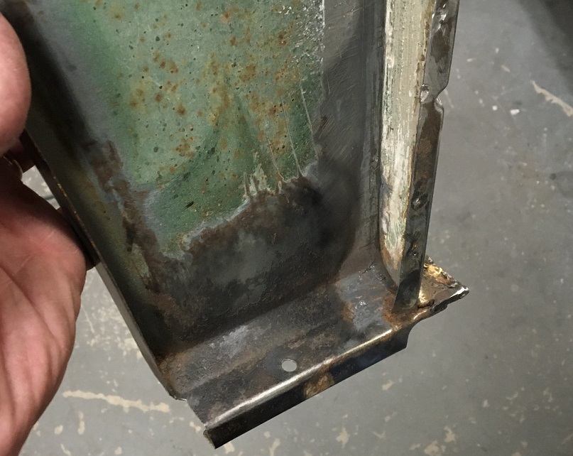
Time to remove the old and replace it with the old.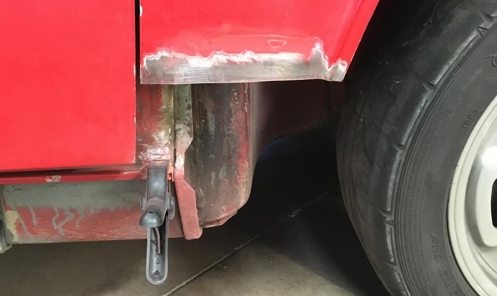
Result: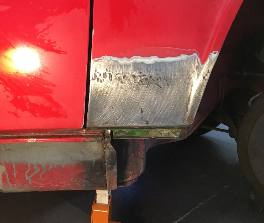
Posted by: Montreal914 Jan 24 2021, 06:10 PM
Looks great. That is a spot on my car I repaired and ended up with a bit to much gap.. kinda sucks as the car is all painted now. I wanted to find wider welting to fill the gap..
The gap was my concern all along. I am happy with the result, but it is a little wider than before. The Restoration Design cowl piece is very nice, but the radius is larger than stock which is very square. The fender top AA piece has a radius of about 1/8"
and was way too far for me to use it. That is why I got a piece from an original fender.
Posted by: mb911 Jan 24 2021, 06:15 PM
Looks great. That is a spot on my car I repaired and ended up with a bit to much gap.. kinda sucks as the car is all painted now. I wanted to find wider welting to fill the gap..
The gap was my concern all along. I am happy with the result, but it is a little wider than before. The Restoration Design cowl piece is very nice, but the radius is larger than stock which is very square. The fender top AA piece has a radius of about 1/8"
and was way too far for me to use it. That is why I got a piece from an original fender.My issue was the replacement fender I put on.. It didn't fit well in both locations so I opted to make it better on the curvature of the door.. some day I may have a another go at it but needed to progress forward.
Posted by: Montreal914 Jan 24 2021, 06:24 PM
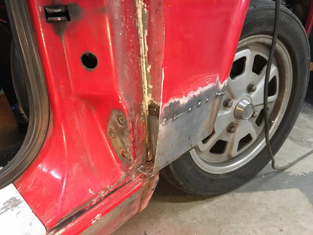
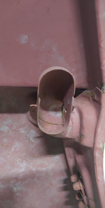
Time to switch to the rear fender of that same side. Another classic, the base of the sail panel. There was a couple of bubbles in the paint, so I wasn't surprised to see rust there.
I cut out the bad area and removed the seam sealer packed underneath and around the vent tube.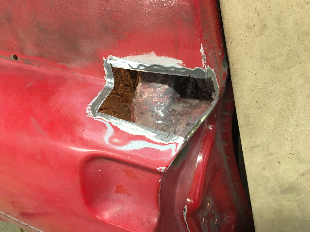
Then, prepared a repair piece and trial fit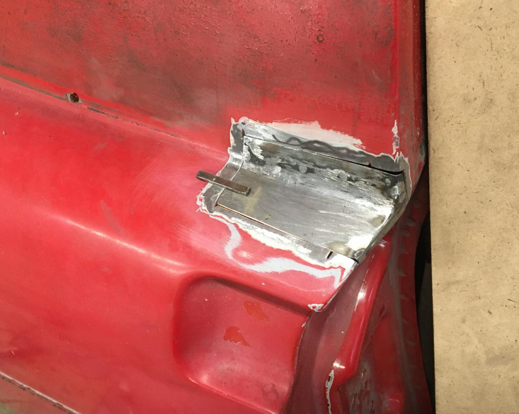
Weld and finish up. I have to say that after fixing the cowl area, this is easy 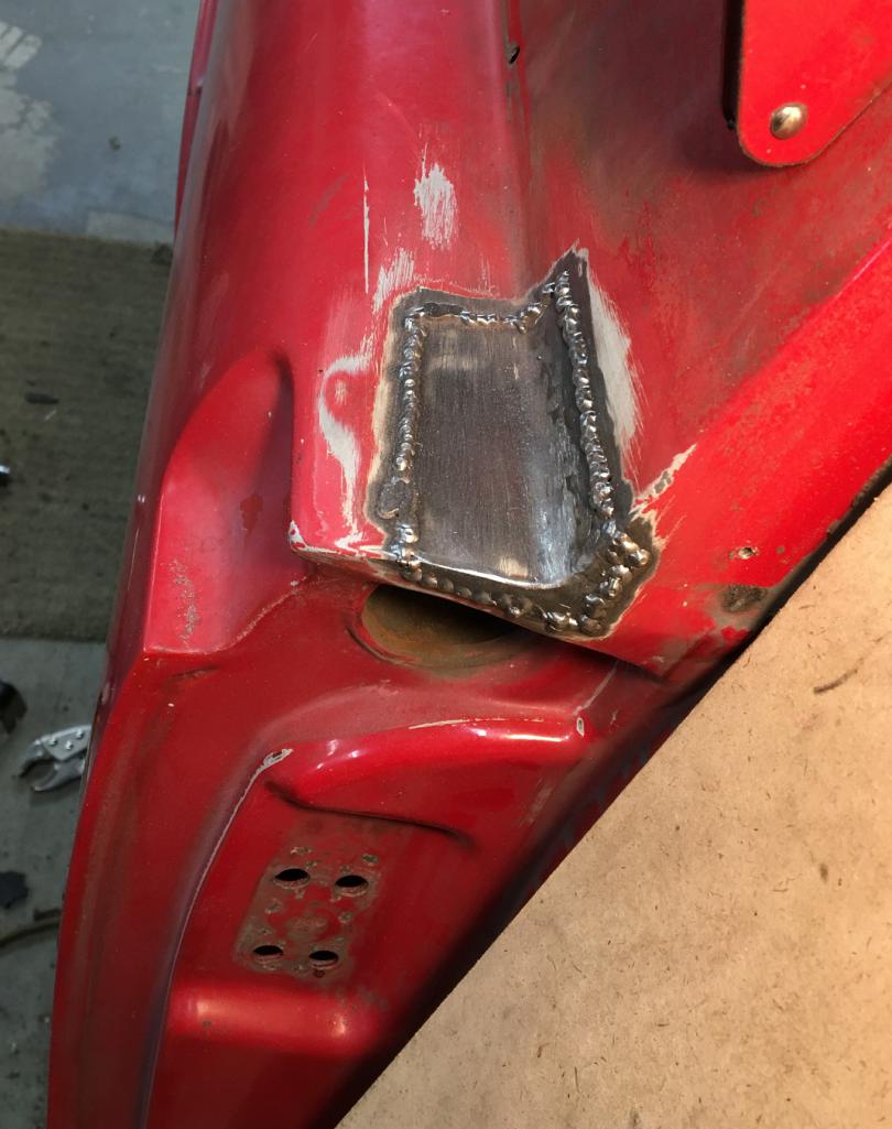
Posted by: bkrantz Jan 24 2021, 08:49 PM
Nice work--keep it up!
Posted by: Montreal914 Jan 30 2021, 09:07 PM
This weeks update:
The door latch bracket deep in the rear fender well needed some help. The cover was rusted on the bottom half. After removing it and threating the area with Ospho, time to start rebuilding.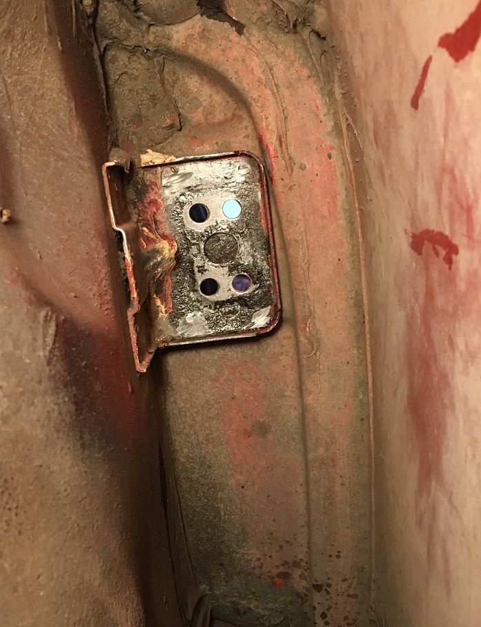
Now with weld through primer and the threaded piece held in place. Good thing i kept on reminding myself to put it there before closing the cover without it, that would have been no fun...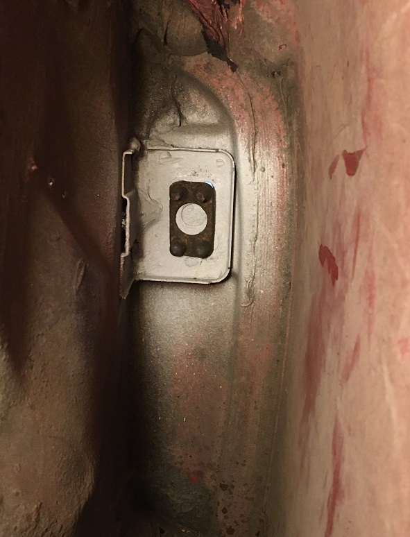
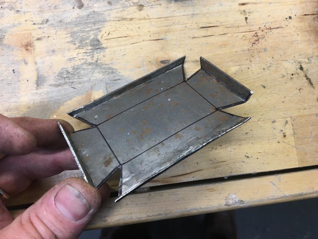
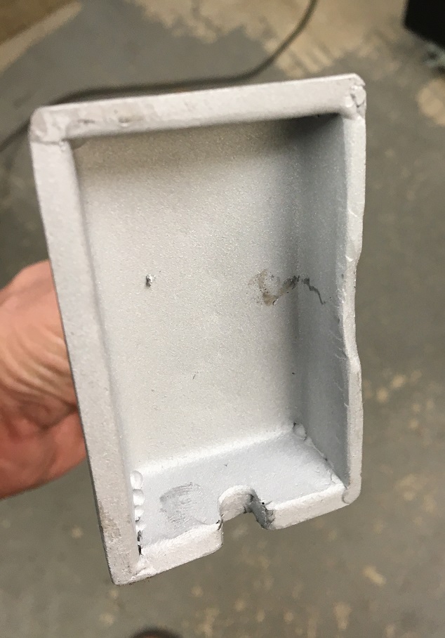
For the cover, I elected to make my own with a template I did, shown here on a spare bracket that didn't end up using.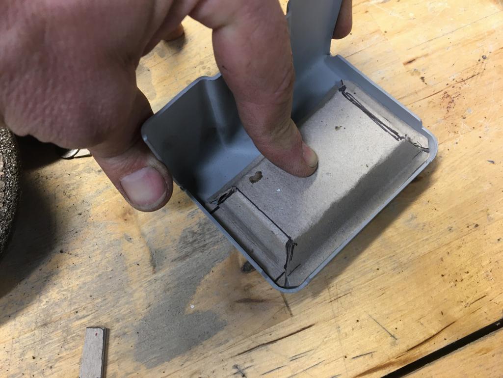
I added a lower opening to spray in some rust protection with a tube later on. Then spray painted with weld through primer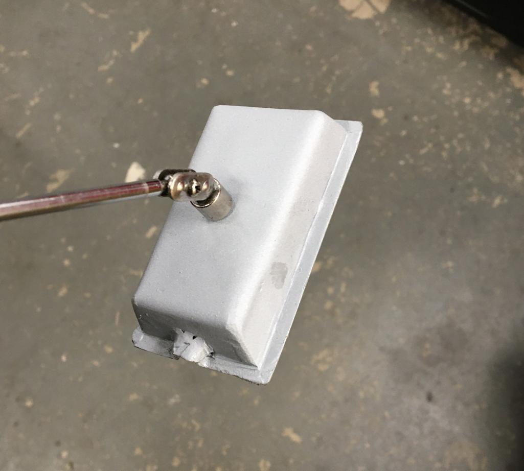
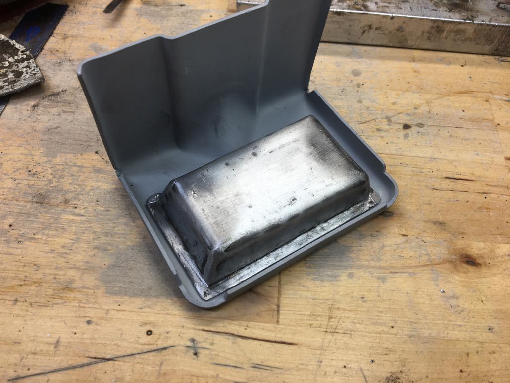
Then held it in place with my telescopic magnet, ready to stretch and weld it afar with my left hand... 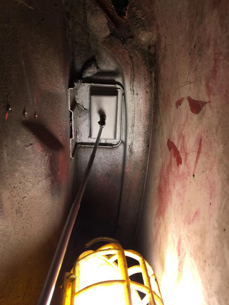
Moving on to the lower fender corner. The one packed with that darn seam sealer that makes things rust...
First the lower part: Repair piece, welded, then finished...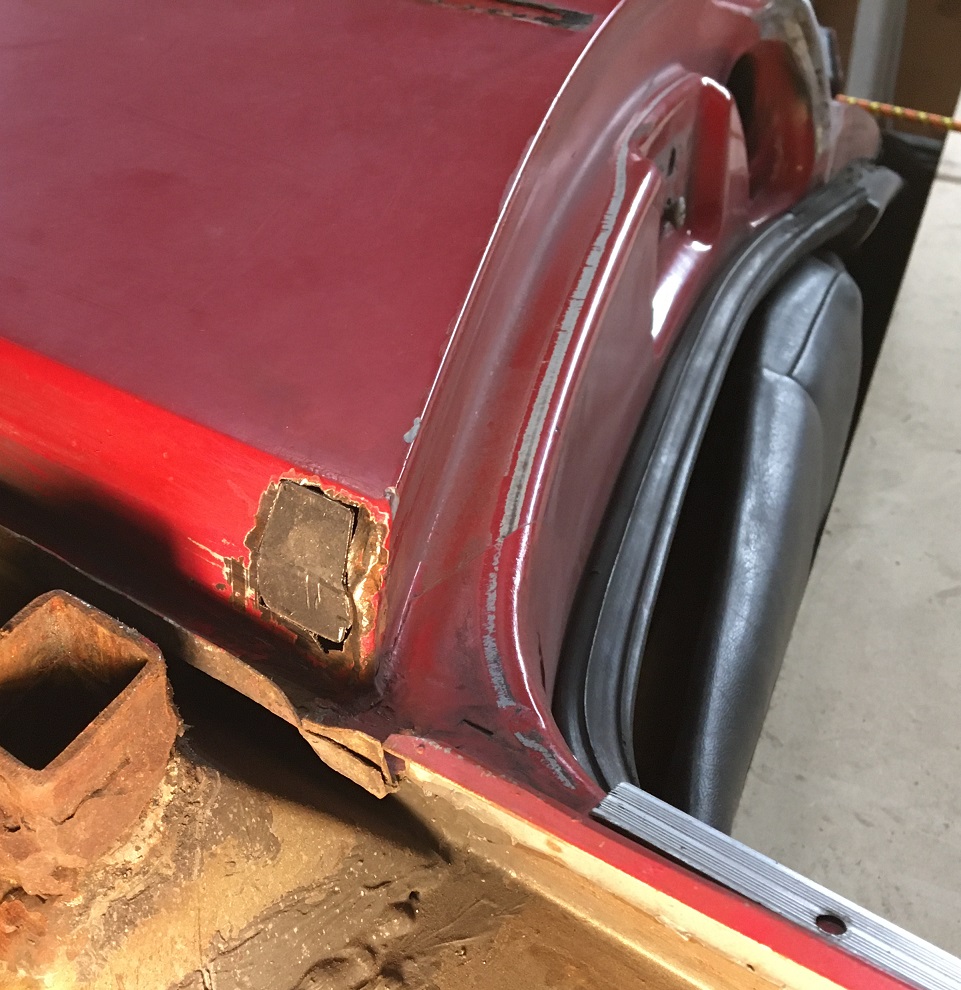
Then the front part: same process...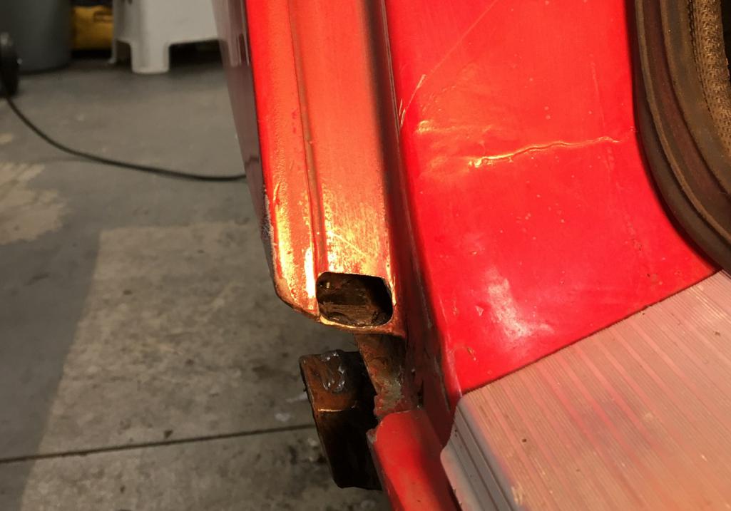
Tomorrow, Sunday, day off  Next weekend, more cut and repair...
Posted by: Cairo94507 Jan 31 2021, 10:18 AM
Very nicely done and great attention to detail.
Posted by: pencap914 Feb 17 2021, 06:22 PM
Nice work Eric! Looks like my 914 will need a similar repair at the cowl. It looks like a daunting task, but this thread is giving me some inspiration to tackle it.
Posted by: Montreal914 Apr 23 2021, 08:12 PM
Fresh update
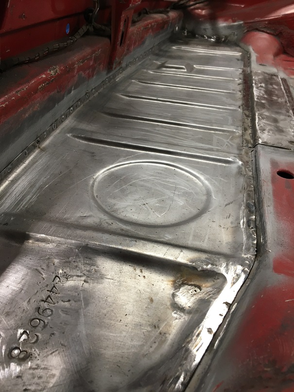
Spent some time finishing the rear trunk floor replacement. First, cutting the crappy rusted through old piece, removing the cross beam reinforcement middle top plate, and brushing the metal clean. 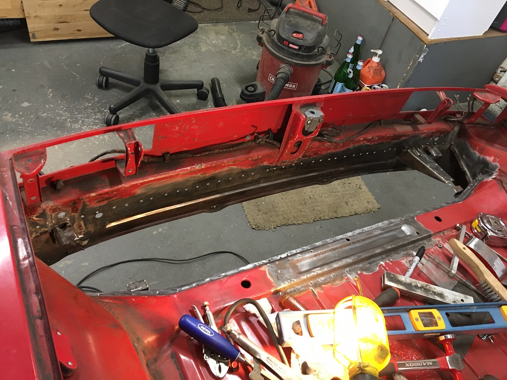
Weld through primer on the weld surfaces.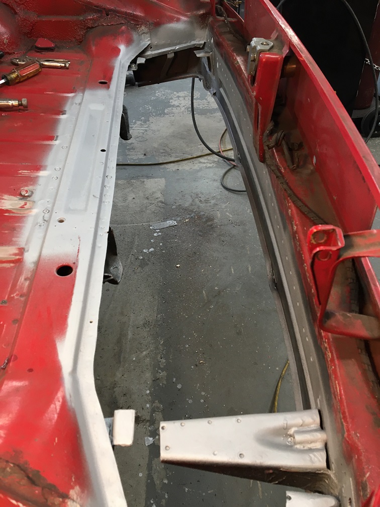
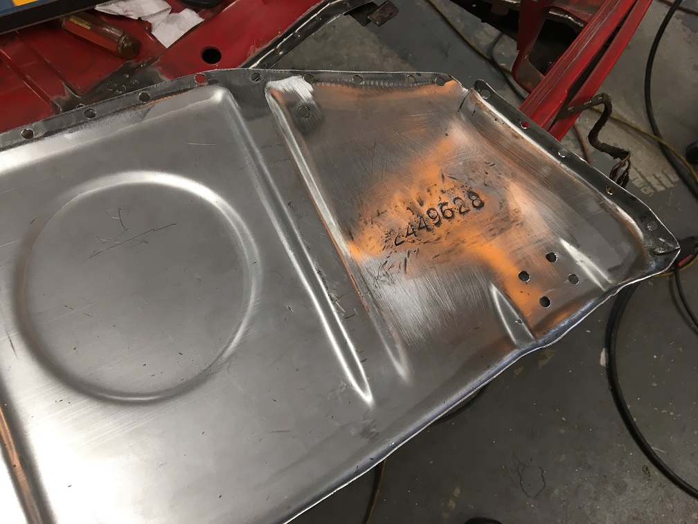
Then the new floor piece from Restoration Design was fitted with the original chassis number plate. And no, I will not cut open the round ports since I don't have a spot welder that needs to go through them . This is a daily driver, not a authentic restoration.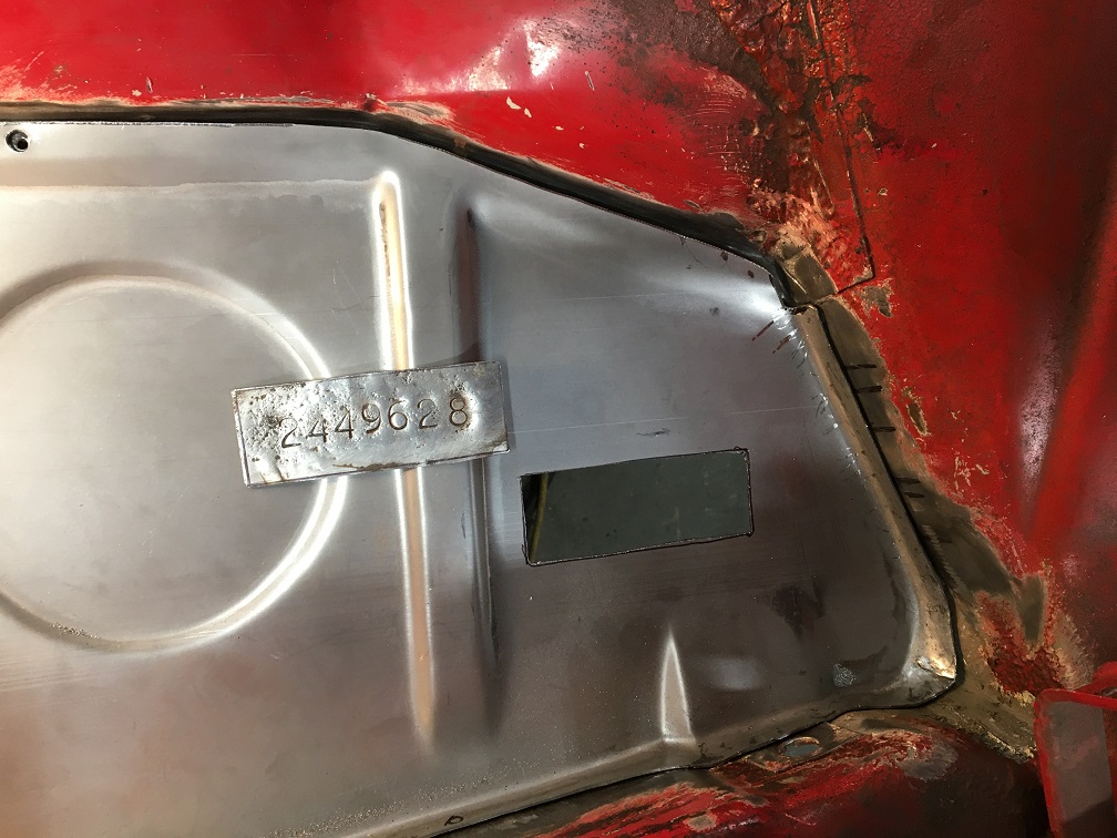
Using the spot welds on the car's back panel as a guide for the floor height, I plug welded the new panel in, then added the recycled reinforcement plate on the cross member. Done. 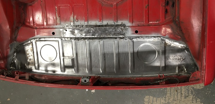
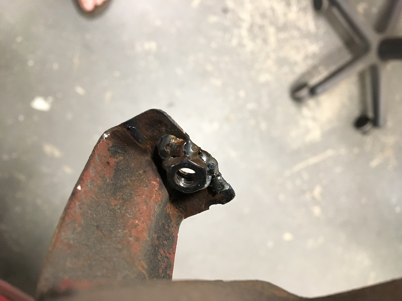
Now for the exhaust heat shield, I elected to screw it to the floor with pan head M6 screws. So I drilled holes and welded M6 nuts on the shield's brackets.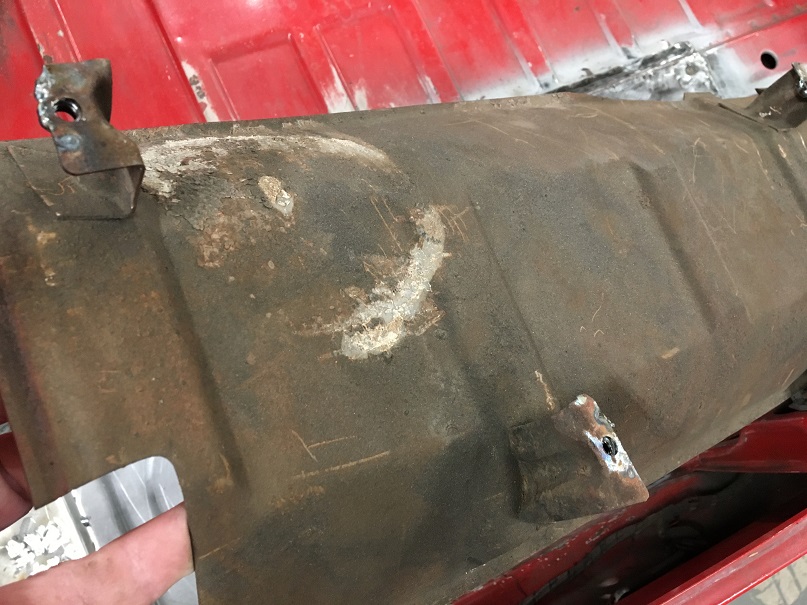
This cardboard template will help me drill the trunk floor in the right spot for the shield's screws.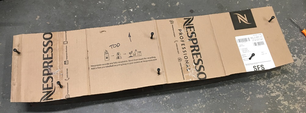
Posted by: Montreal914 Apr 23 2021, 08:47 PM
Battery tray! 
Some like to weld it in place, others screw it so they can paint the inside of the support. I chose to install it with screws, which was the long route...
First, for battery I am using an Odyssey PC925 which is a lot smaller that the stock battery tray. Also, as a requirement from the POC rules, the battery is supposed to be held in place by a cross bar on top. So all this led to this bit of re-engineering of the tray and its support.
First let's look at the support. I extended the folds, drilled holes and welded M8 nuts (3) on the backside for the tray to attach to.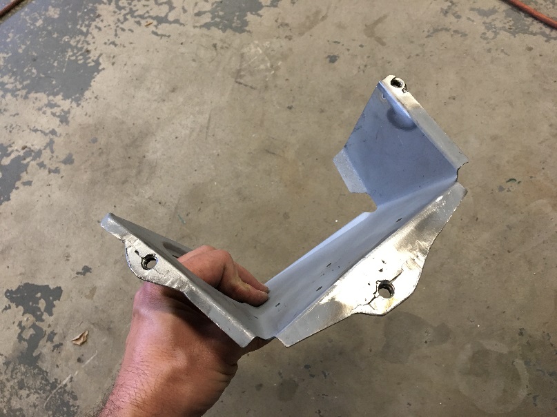
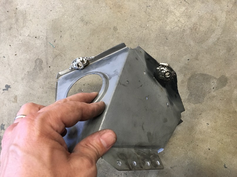
Next the tray was also modified. For the top cross bar, I intend to use 2 M8 treaded rods that will be attached to each side of the tray. The first one will use the nut on the middle of the angle seen in the picture below. The second rod will use the nut where the stock "Z" shaped bracket normally bolts on. Also on the angle, we can see two M8 nuts for through the inner fender anchoring bolts.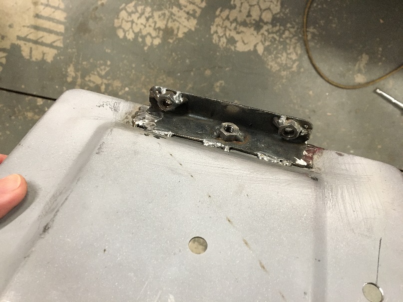
Here the tray rests on its support with the holes lining up to the nuts on the support underneath. As mentioned, the Odyssey battery is smaller and will actually fit between the heads of the front and back screw, and between the threaded rods that will be on each side.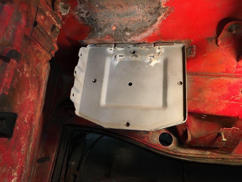
Finally these are the M8 screws through the inner fender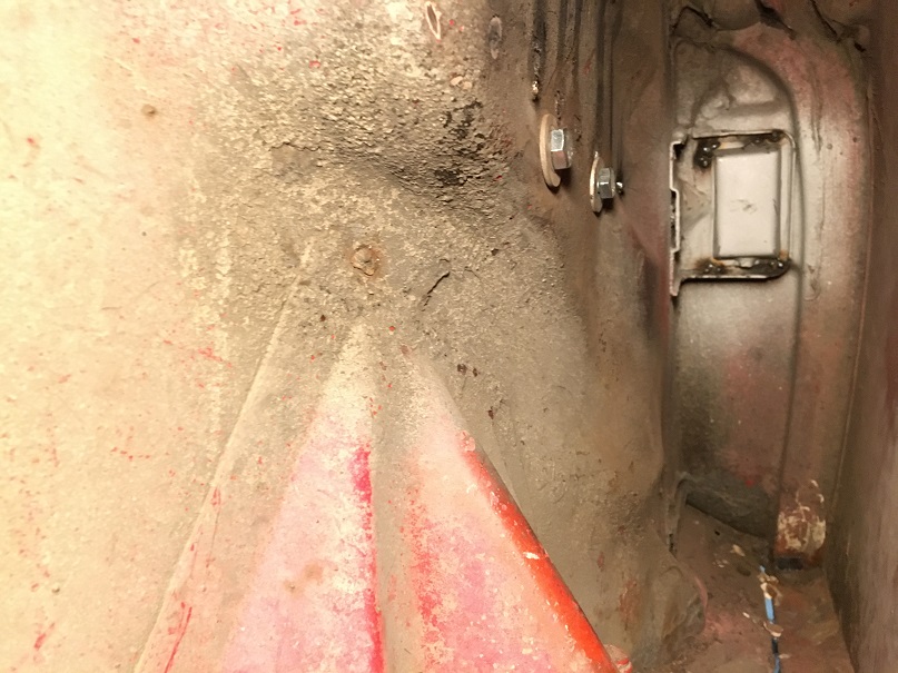
Posted by: Root_Werks Apr 26 2021, 03:24 PM
Really like this thread! You've got some skills, inspiring!
Posted by: Montreal914 May 1 2021, 03:55 PM
Really like this thread! You've got some skills, inspiring!
Thank you.
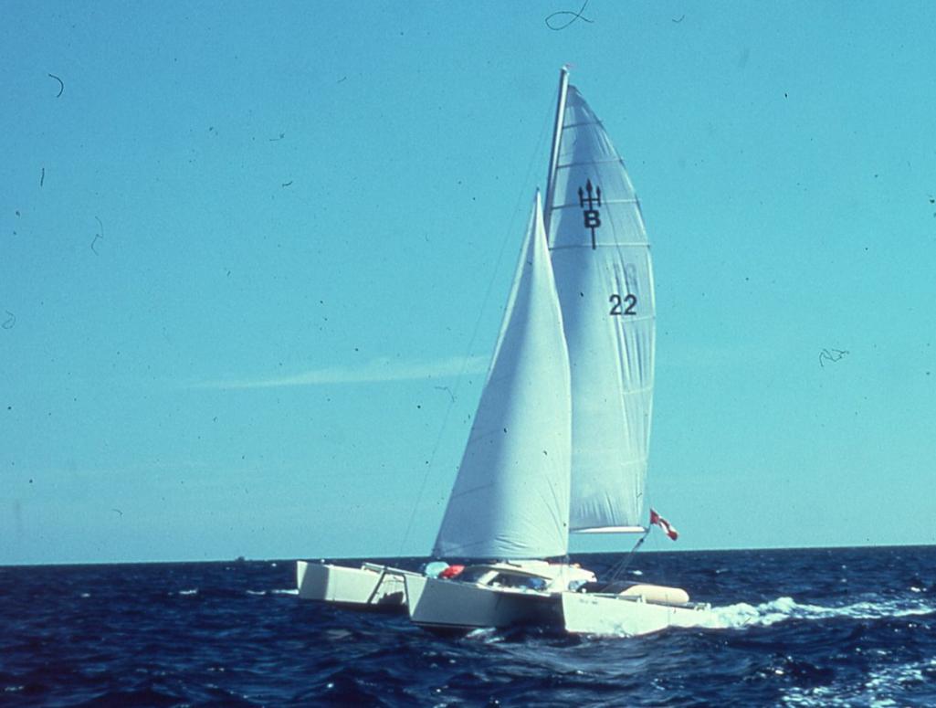
I am happy with most of my work's results. Although this is my first attempt in this kind of work, I owe it to my dad who taught me my hands-on and mechanical skills. The year I was born, he began building a trimaran sailboat from a set of Australian plans in hopes of taking us sailing in the Bahamas. 8 years later, in '78, We towed the boat driving from Montreal to Miami, set it to sea and went discovering the Bahamian islands on this lightweight flying machine! In a way, similar ideology with our beloved 914; very light and nimble.
Posted by: Montreal914 May 1 2021, 04:00 PM
Now back to the main program...
Removing the carpet on the driver's side long, I noticed the classic crack on the hand brake area. The car currently has a Brad Mayer stiffening kit on the outside.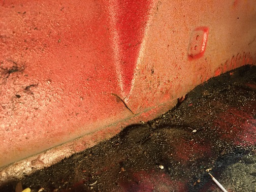
What is the recommended method to fix this? Simply weld up, cut the area and replace with fresh metal, weld and double up with a extra layer?
Posted by: bbrock May 1 2021, 06:02 PM
I just got caught up. Fantastic work. I'm enjoying getting to ride along.
Now I have to ask, where is that boat now? That is epic!
Posted by: Montreal914 May 1 2021, 09:25 PM
I just got caught up. Fantastic work. I'm enjoying getting to ride along.
Now I have to ask, where is that boat now? That is epic!
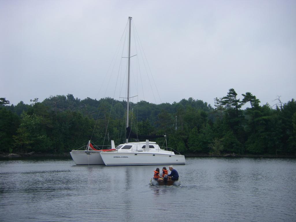
@http://www.914world.com/bbs2/index.php?showuser=20845 ; I am not sure of the current condition of the 24' long x 19' wide little trimaran made out of 3/16" thick plywood. I will ask him if he has fresh news from the new owners. In the early '80s, my dad traded it with extra money for a home built fiberglass foam sandwich 39' x 20' catamaran with a 45' mast from the same Australian designer. That one weighted 8,000lbs, which is still very light weight and very quick for that size sail boat. We enjoyed it as he improved it over the course of many years. He sold it a few years ago, as the maintenance and the navigation became too much for my parents who are now in their 80s. Below, picture taken in 2009 of him with our two daughters, a few month before our move to California. This was on lake Champlain upstate New York near the Canadian border.
All this nautical distraction is very nice, but we are here to share about 914s
So, what is the consensus on fixing the crack on the driver side inner long...
Posted by: bbrock May 1 2021, 10:18 PM
Thanks for the update on the boat(s). Fantastic.
As for the crack, I'd say just weld it up, especially with the stiffening kit. I had to replace that whole bottom section on mine due to rust. I figure by the time it cracks again, I'll likely be long departed.
Posted by: Montreal914 May 1 2021, 11:47 PM
Thanks for the update on the boat(s). Fantastic.
As for the crack, I'd say just weld it up, especially with the stiffening kit. I had to replace that whole bottom section on mine due to rust. I figure by the time it cracks again, I'll likely be long departed.
Yeah, I will do that and maybe add another layer with plug welds. Thanks!
Posted by: Montreal914 Aug 13 2021, 11:35 AM
Wow, already about 3 1/2 months since my last post!
Well, there was some progress but not as much as I would have hoped for.
Next on the list are the trunk hinge base mounting points. The left side one had the captive cylindrical nut detached from the base, and the right side one had been rewelded in the course of the car's life, but not in the correct location.
Removal of both sides: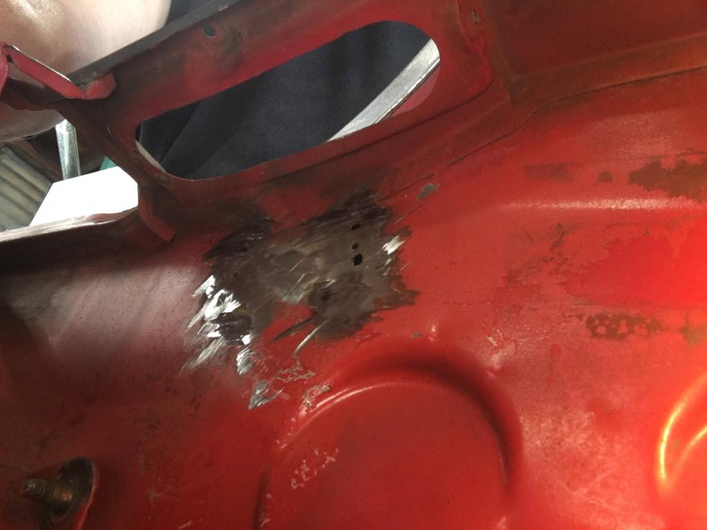
Repair the holes: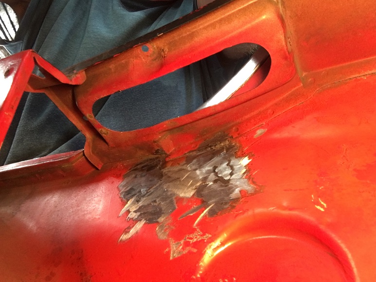
The new hinge base have a couple of good tacks on the back side for the cylindrical nut. But I decided to add some more on the front side... 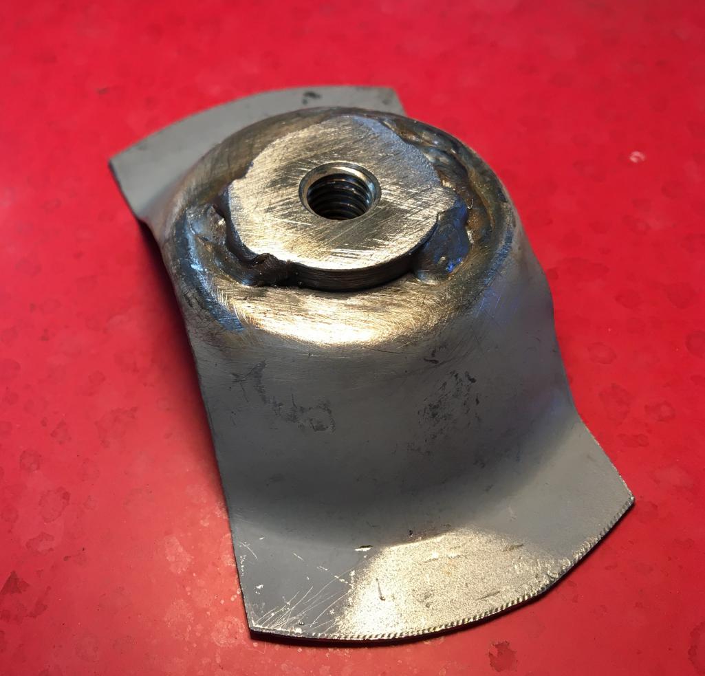
To make sure the new hinge were installed in the right location, I placed the trunk lid on the car, and using sockets as shim in all four corners I adjusted the height and gaps. I also made cross marks on tape to easily reposition it later.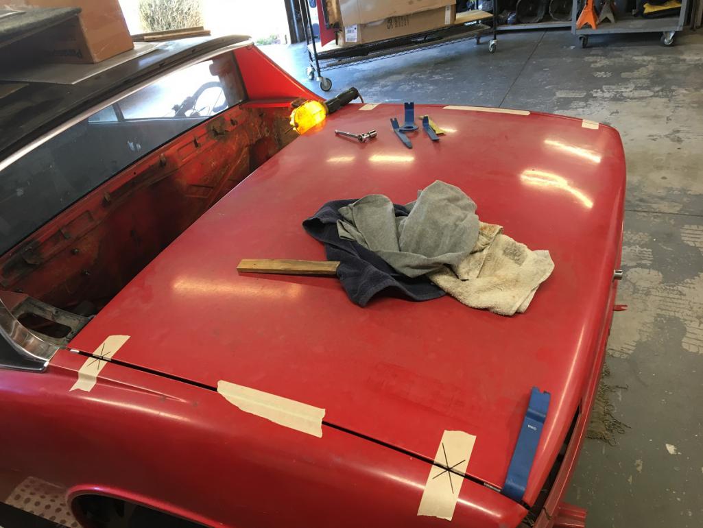
Once happy with the trunk lid alignment and fit, I screwed in the hinge base to the trunk hinge bracket with a new shoulder bolt and marked where it would be set on the body.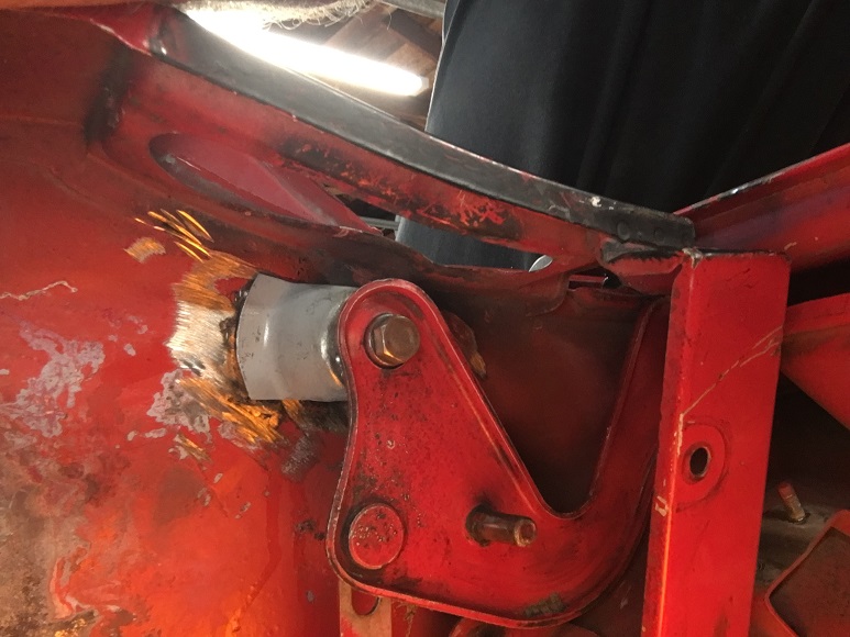
After marking both hinge base to the body, I removed the trunk lid, installed the hinge bases with self tapping screws and installed the lid again for final verification.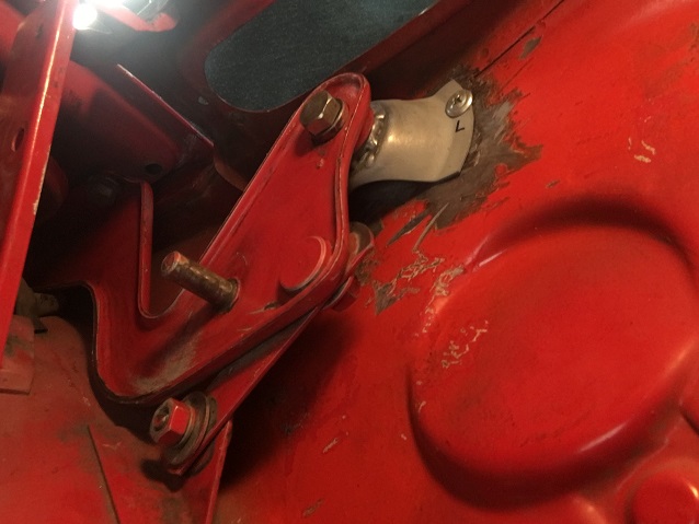
Measure twice weld once 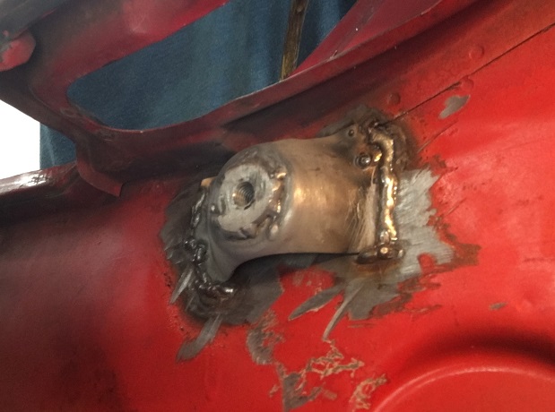
Third trunk lid test install, everything operates smoothly and lines up nice. No picture but you get the idea.
Posted by: Montreal914 Aug 13 2021, 12:04 PM
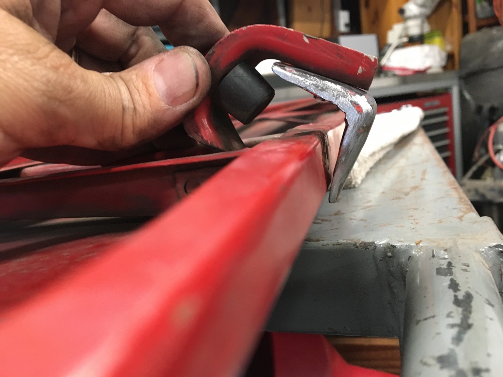
Time to move on to the engine lid, which also needs help...
Typical 914 engine lid bracket issues, both have been repaired, but the passenger side one is broken again. 
I got a pair of original brackets at one of Bruce Stone's swap meet a while back knowing I was going to need them.
These typically fail in two ways:
1- at the bend (like mine)
2- detach from or rip the firewall.
Thinking of ways how to prevent this to happen again, at least problem #1, I did this little clearance study: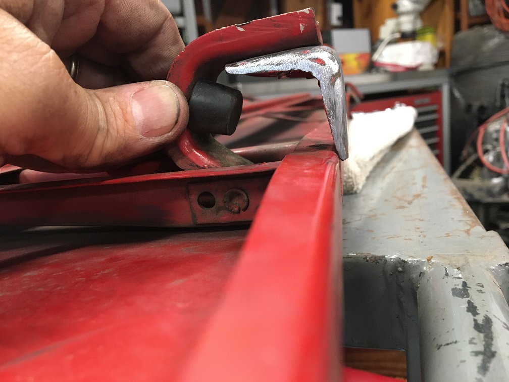
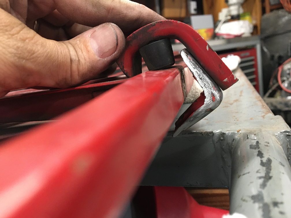
Clearly, there is room on that "L" bracket to add a gusset on each side making it a lot stronger.
So here we go! 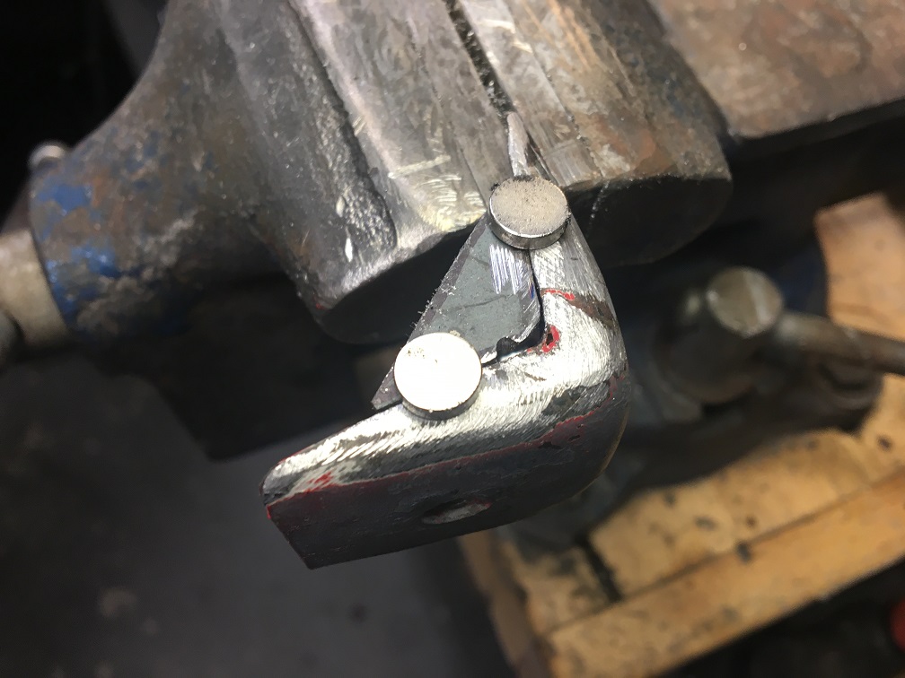
Once done: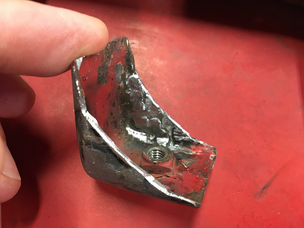
After a little trimming and adjustment, here is the updated clearance study: 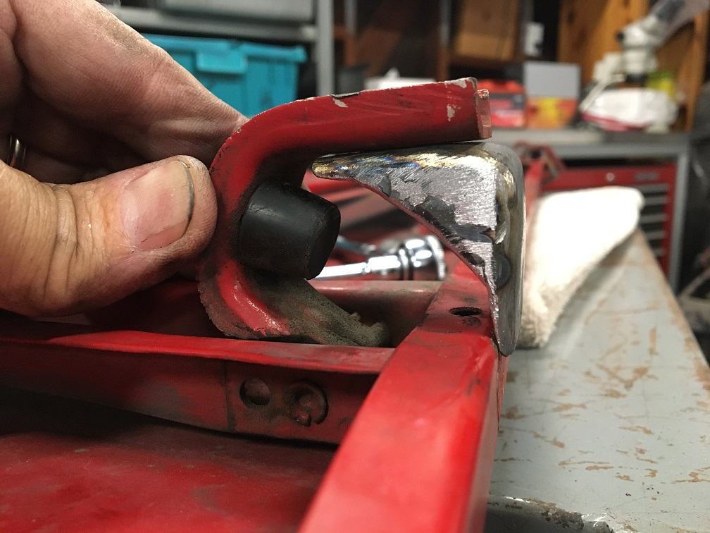
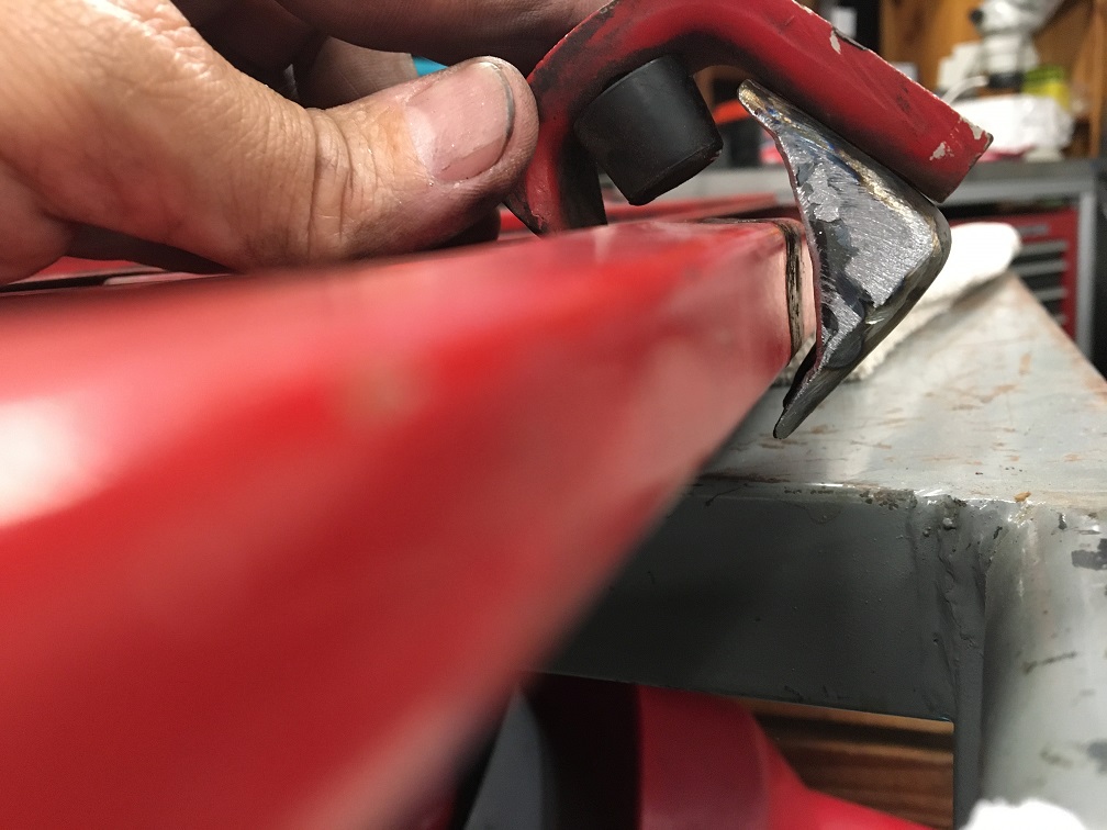
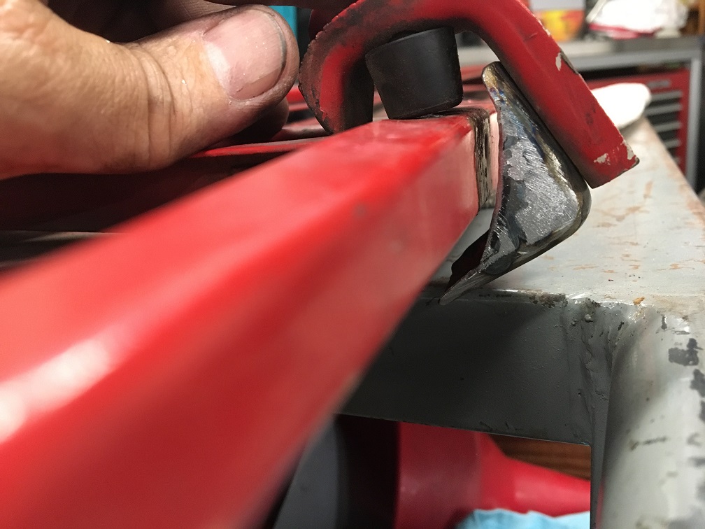
I am pretty sure this is the end of the bracket cracking problem!
Here the rebuilt bracket is welded to the firewall on the sides catching more of that embossing. Hopefully, this will also prevent problem #2 explained earlier. That being said, all of these issues can probably be avoided by holding the engine lid as it is being released. An easy good habit that many of us have very early on adhered to for obvious reasons. 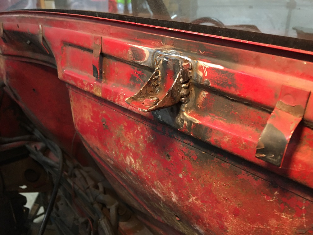
Not shown, but the engine lid was properly aligned to the body in order to set the "L" bracket in the right location on the firewall.
Posted by: Montreal914 Dec 12 2021, 01:56 PM
Wow it has been many months since I have updated this thread. The good news it that I did make progress!
Planning ahead, I am doing modifications to the oil network. Although this is a 4 cylinder car, I intend to stroke my current 2056 to a 2258 (2270) in the future. So I already have made changes on the engine side as described in this halted (for this body work) Microsquirt thread:
Post #46 here: http://www.914world.com/bbs2/index.php?showtopic=342361&st=40
I made an aluminum panel for the remote oil filter and thermostat. I will be using a rabbit/jetta diesel filter which is rather large (almost 1 quart). 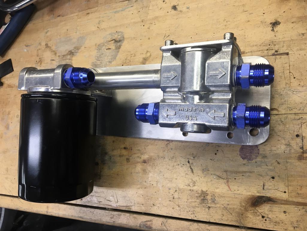
I welded 4 cylindrical tapped standoffs (911 part) to the lower right portion of the firewall to mount the assembly. The filter is high enough to be fully protected. The oil lines from and to the engine will connect in the middle area of the assembly, while the lines to the front cooler connect to the right side of the thermostat. This also clears the heating flexible tube between the heater valve and body heater duct.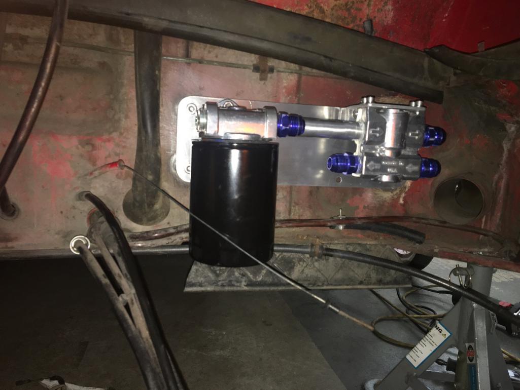
More to come... 
Posted by: Montreal914 Dec 12 2021, 06:18 PM
Between the filter/thermostat assembly and the front cooler, I plan on routing the lines along the outside of the passenger long. About 10 years ago, I fitted the car with a Brad Mayer reinforcement kit which actually butts in on the back side of the tapered box in the front of the long. Since it sits away from the outer long of about 3/8", it is obstructing some of the box' backside preventing me from drilling holes large enough to run the lines through the box à la Elephant racing hard lines. Therefore I had to create a channel in the box to make room for the lines.
Here is the box with the reinforcement kit butting on its back side: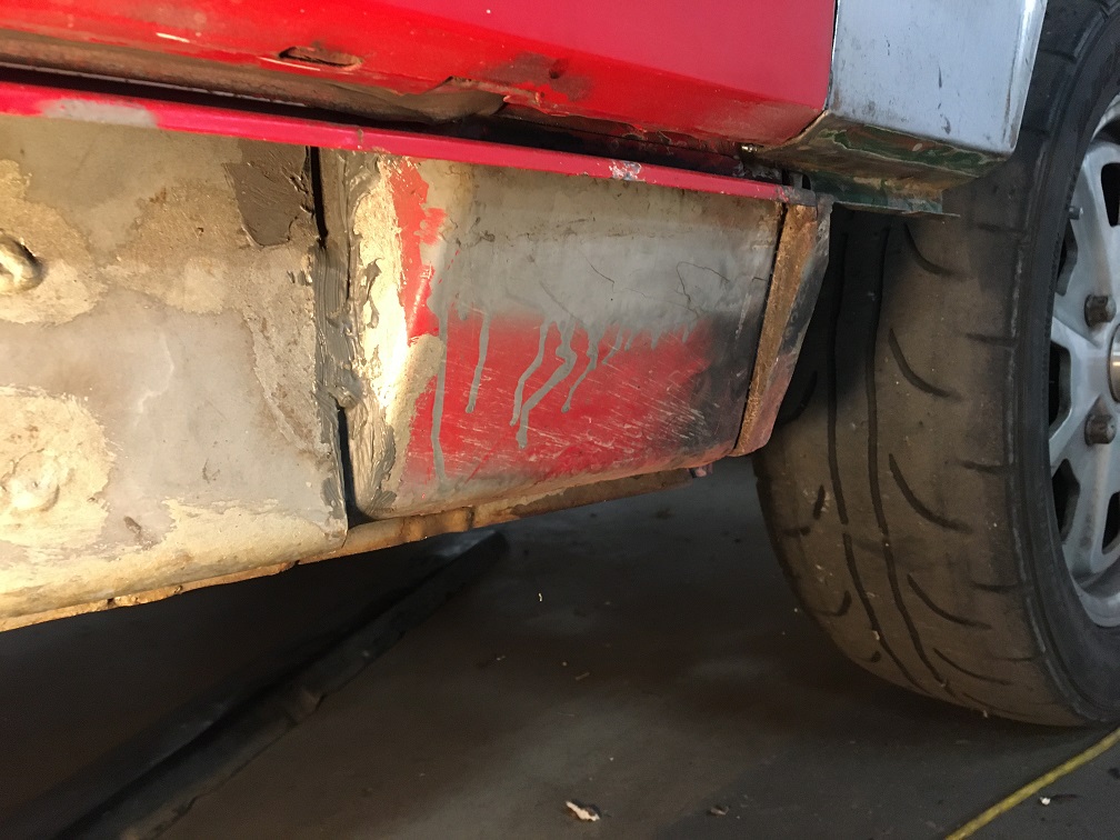
Now the box has been opened up with the removal of the lower front corner that was rusted: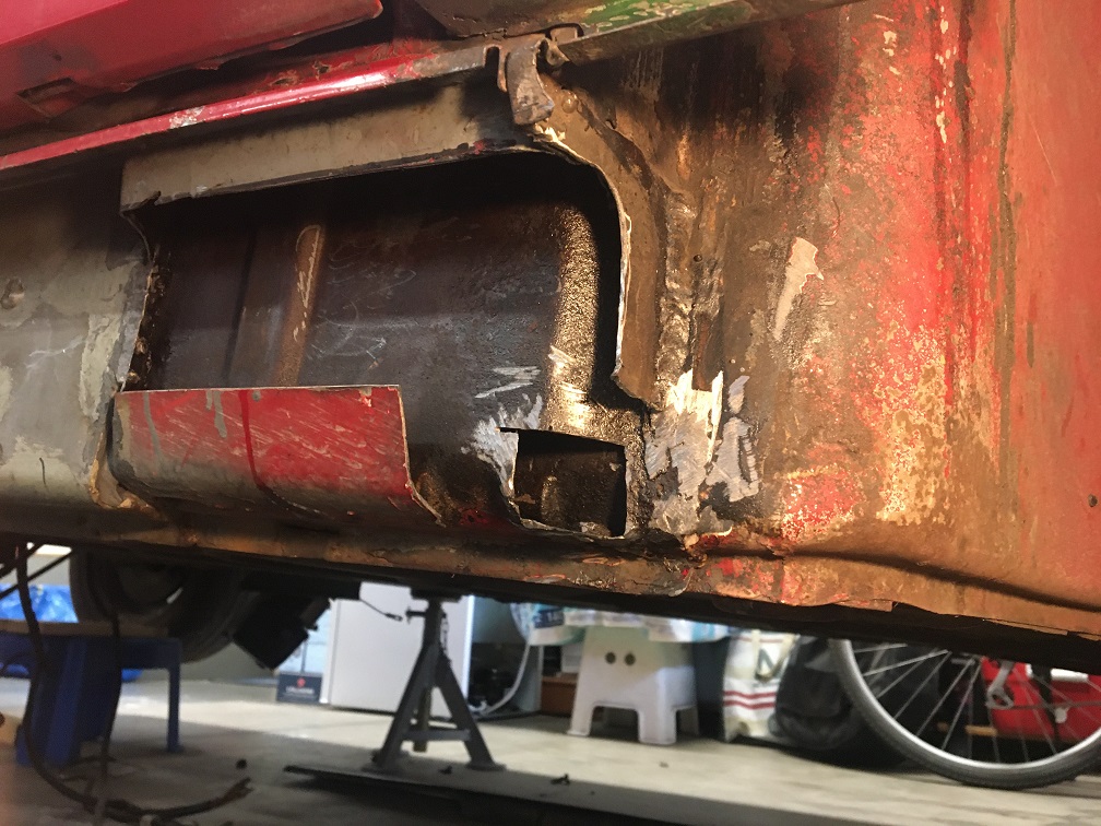
Patching the corner: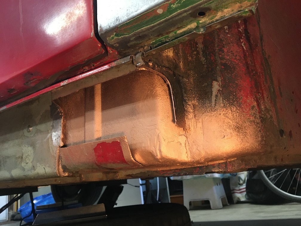
And now putting back the lower front part of the box leaving a trench for the lines to go through: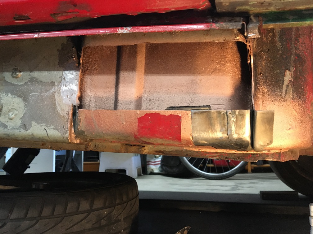
Finally, after shaping the trench from a flat sheet, I closed up the box to keep some structure integrity. Shown here with my line mockup: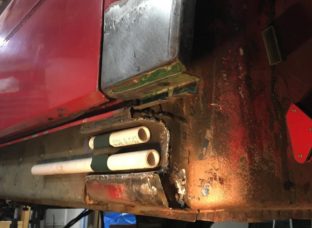
Next, the jack point pyramid had to be trimmed for the same purpose. This pyramid is part of Brad Mayer's kit and is made of thick steel: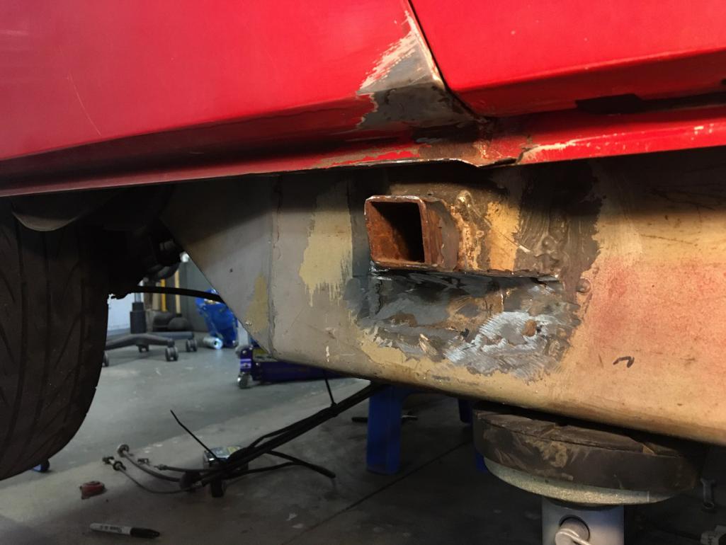
At this point the path is clear to run the oil lines along the passenger side longitudinal beam.
Posted by: Montreal914 Dec 12 2021, 07:19 PM
Although I could have elected to use steel braded lines or rubber hoses, I really like the idea of having rigid oil lines. Being on a tight budget, I studies my options and decided to use aluminum 5052-0, 3/4" x 0.049" tube from Aircraft Spruce. These come in 6 foot length and cost $39 ea. They also sell the -12 AN flared tube sleeve and nuts for them at very reasonable price (~4$ ea). Total material cost ~$105!
Since I am not in business of bending tube, I got a cheap 3/4" tube bender on ebay for $38 and was ready to get crafty. After very carefully studying the path I wanted to take, I started bending, knowing there wasn't any room for error since I was going to need the entire 6 feet to go from the back to the front.
First bend: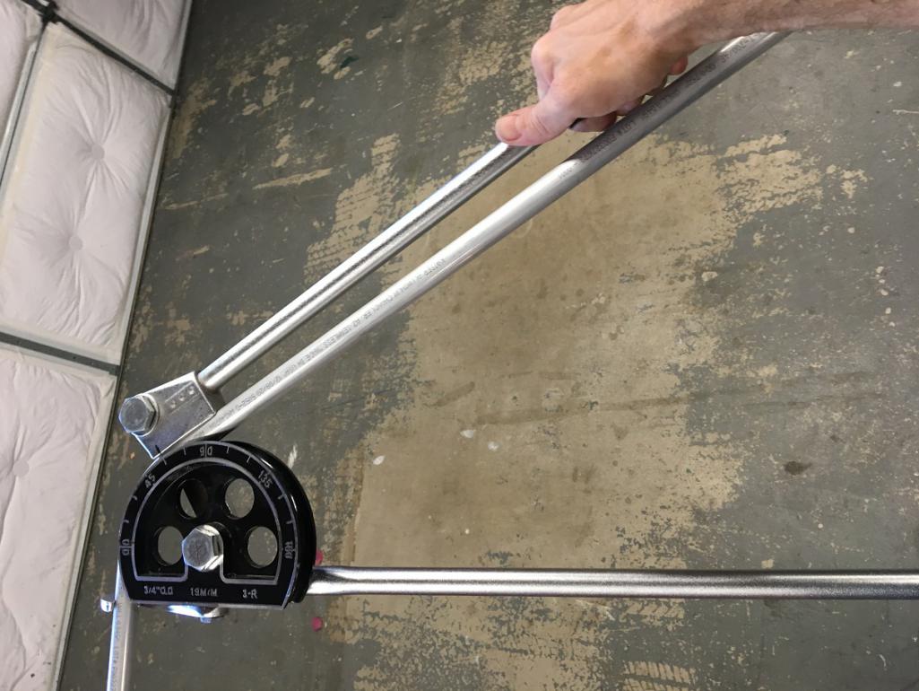
Without being perfect, I was actually pleased with the result that this $38 toll was giving: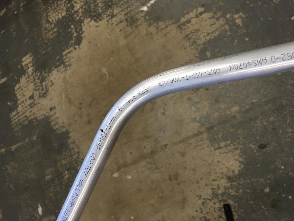
After a few hours of trial fit and bending, I was making encouraging progress. The thickness of the Brad Mayer panels allowed me to drill and tap M6 holes to mount the Abel style SS clamps (Amazon $11):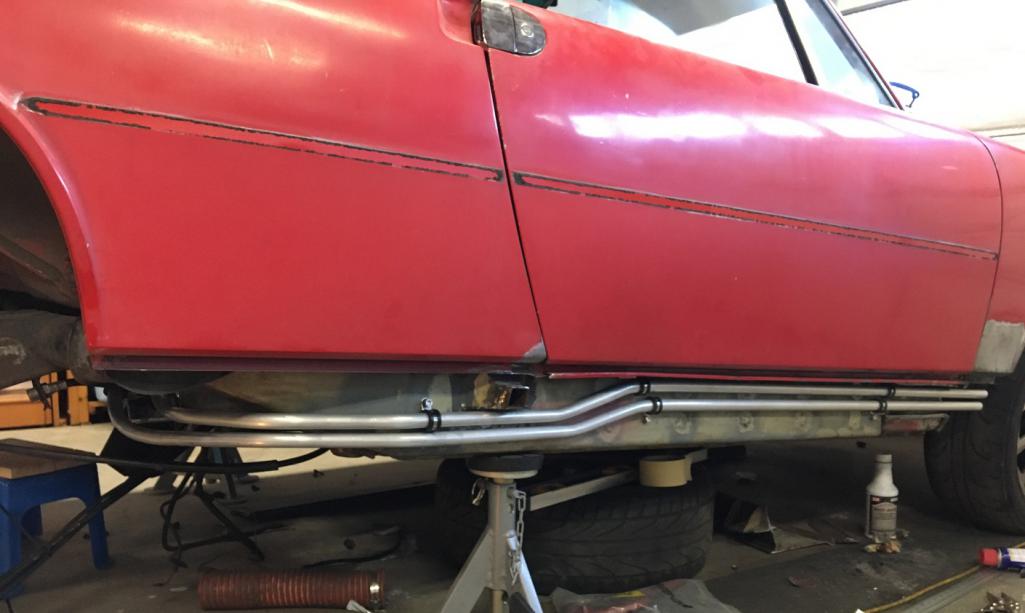
Details of the back end: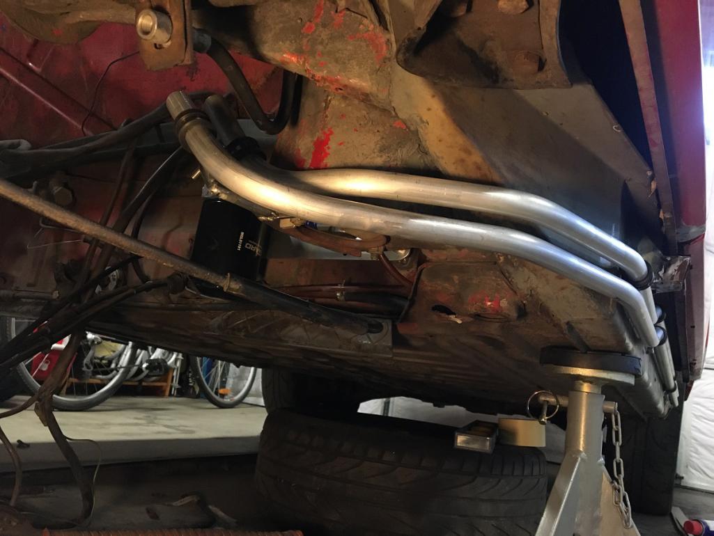
Then I fabricated a rear support that will use one of the two engine mount bracket bolt: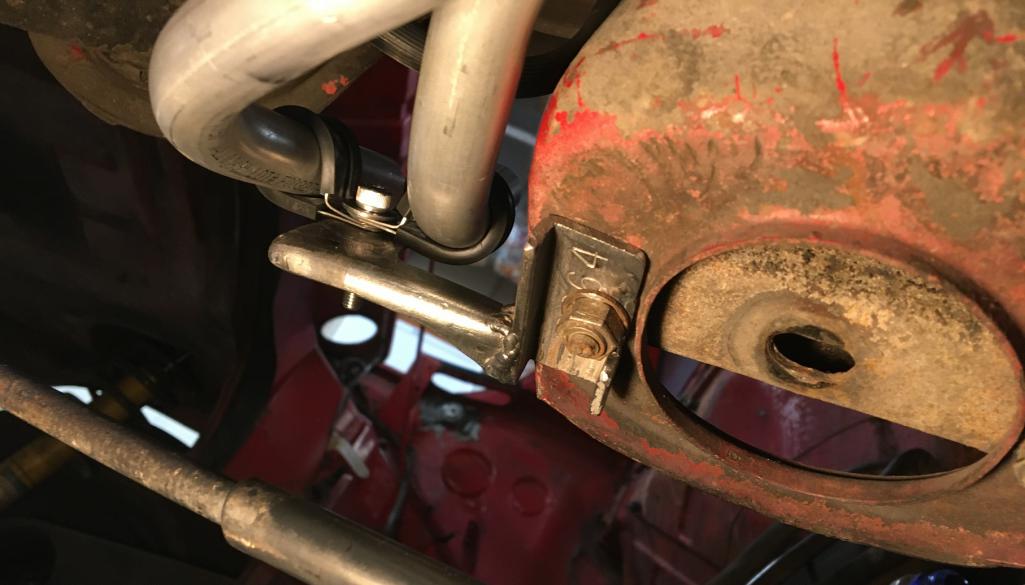
The last few steps were to complete the ends. This mean trimming the length on the back end and bending the front end upwards in the fender well. Last, obviously install the AN fittings and flare the end of the lines. For this I was fortunate enough to borrow a 37degree flaring tool from a friend.
Result once flared: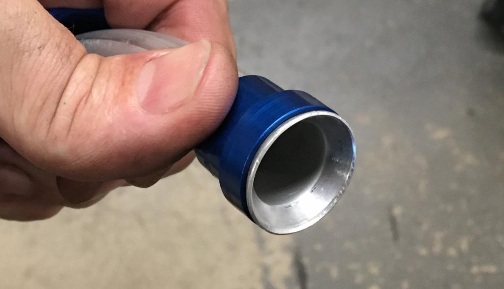
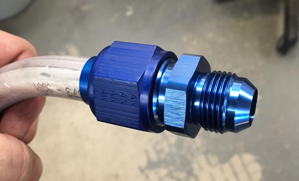
And the final pre-installation with fitting and mounts. I plan on fabricating a front support to hold the lines at the junction with the flexible lines. The front mount should serve two purpose: supporting the end of the rigid lines and being an anchor point for a partial fender liner to protect the lines from flying road debris.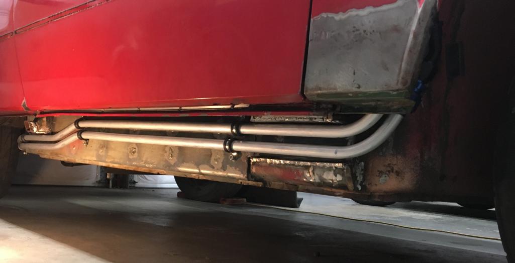
Inner fender area: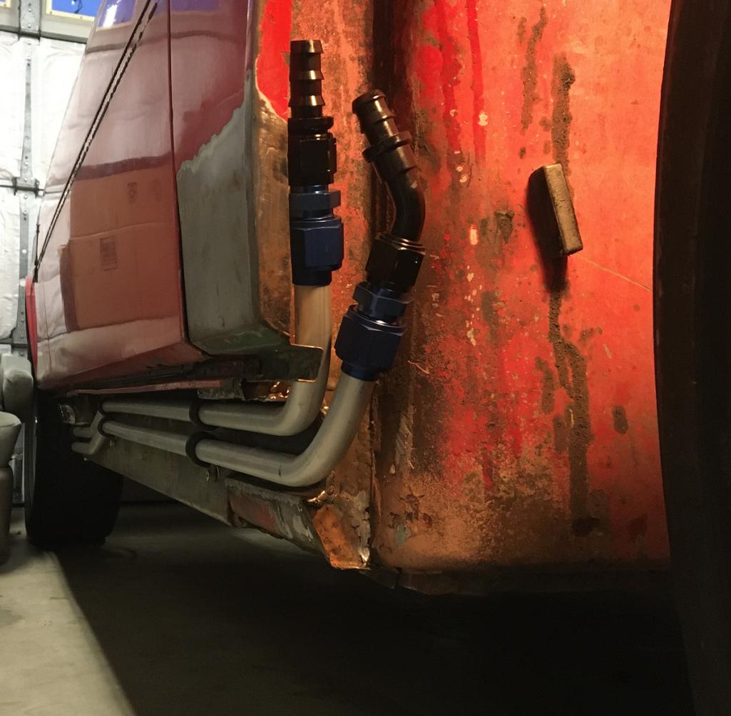
And finally, the back end with the mockup connection to the filter/thermostat assembly: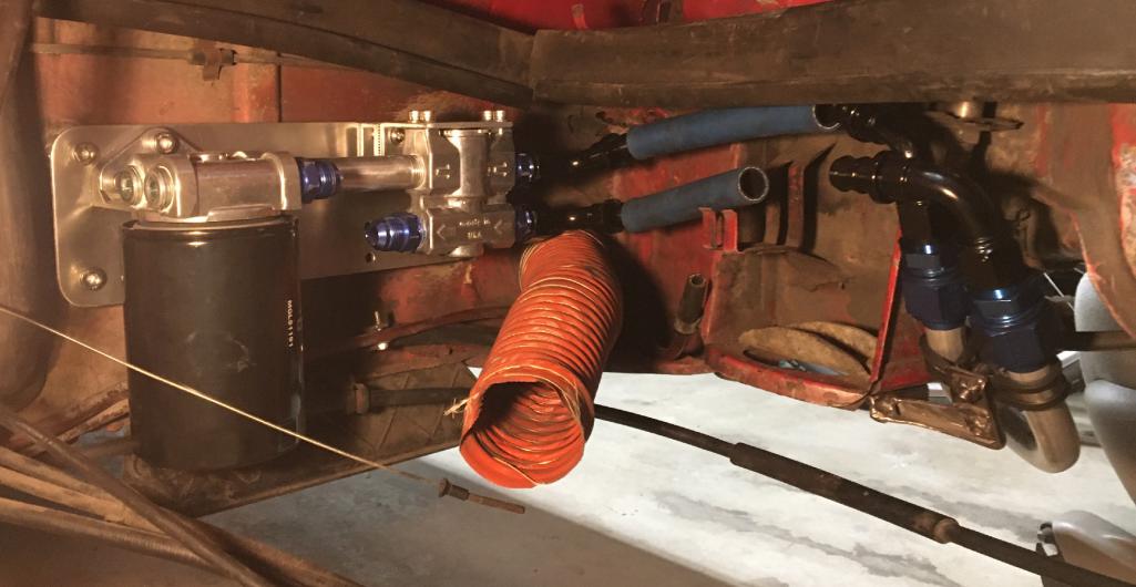
And there you have it! My $115 rigid oil lines!
Posted by: Montreal914 Dec 12 2021, 07:45 PM
Now, that the rigid part has been completed, it is time to look into how we will get to the front oil cooler. Connecting to the rigid lines, I am using -10AN Parker push-lock hose.
After locating the right spot to make the openings in the body, I used a knock-out tool I got for $35 on Craigslist. This makes this task a breeze. This a picture of the upper left trunk area near the lid hinge (removed) and windshield washer bottle area.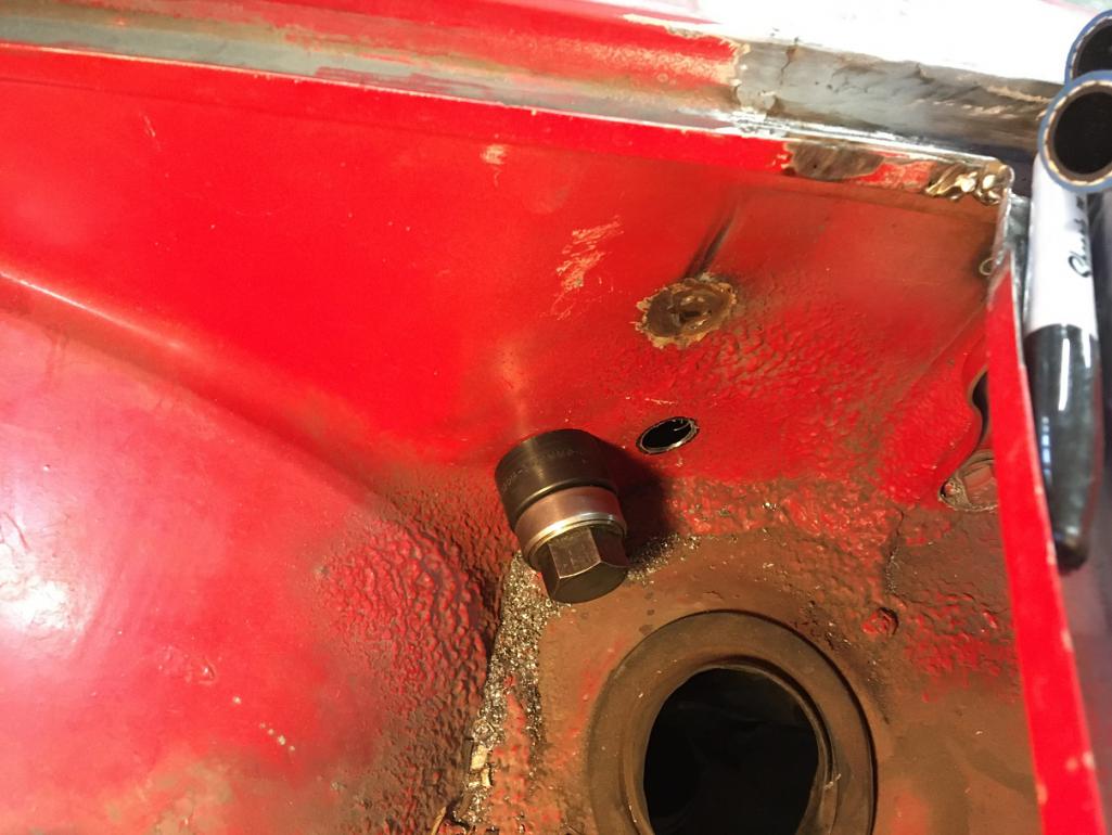
And now with the grommets: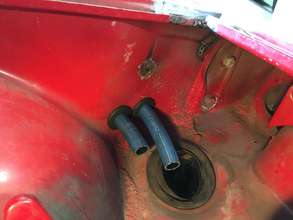
The next openings are through the lower part of the partition wall between the trunk and the fuel tank area. This being a little tighter area, I had to get the lines closer and overlap the holes. We are looking at the rear bottom left area of the front trunk. Next to the paired holes is the air pressure line from the spare to the washer bottle.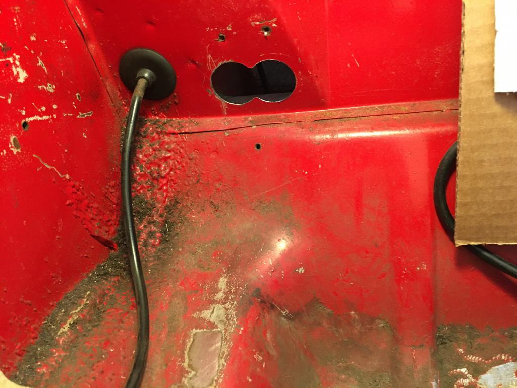
And finally, with trimmed grommets and mock up hoses (out of focus picture but you get the idea... :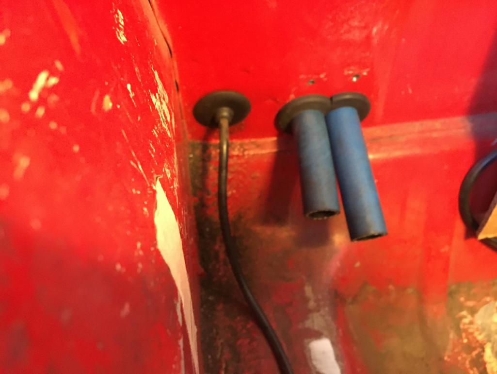
So the final result looks like this in the fender well: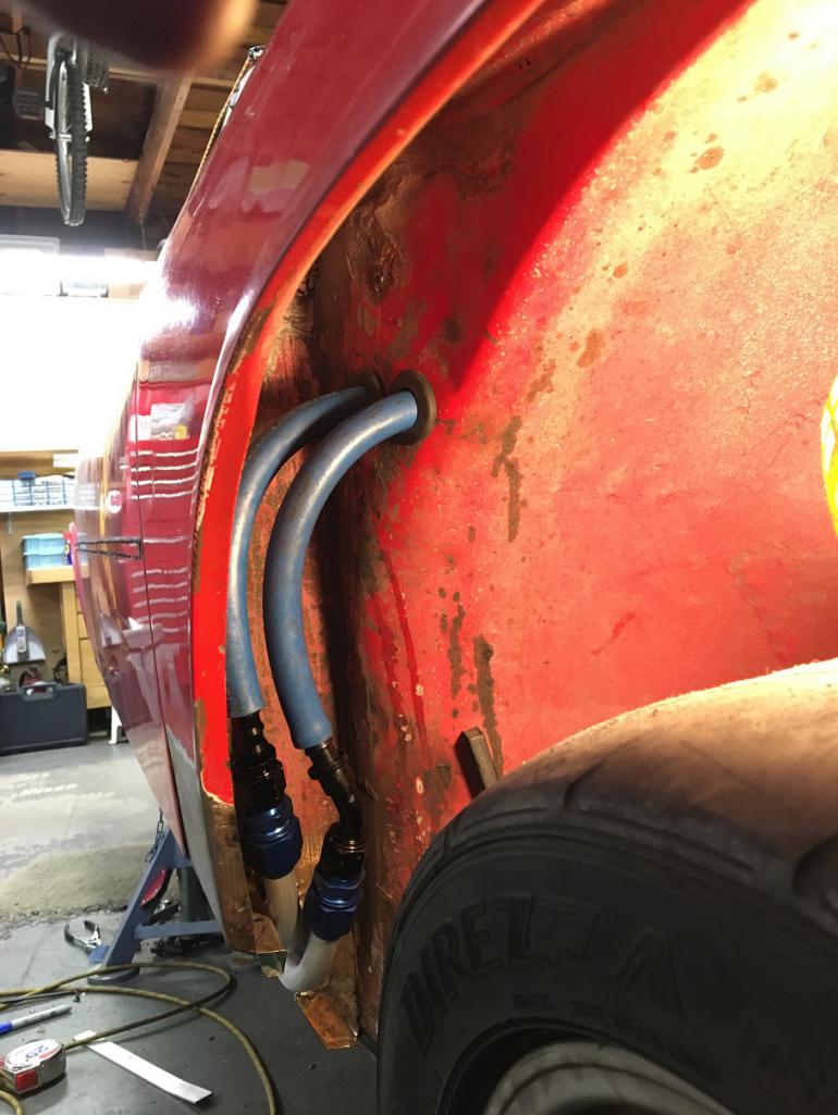
And in the trunk area: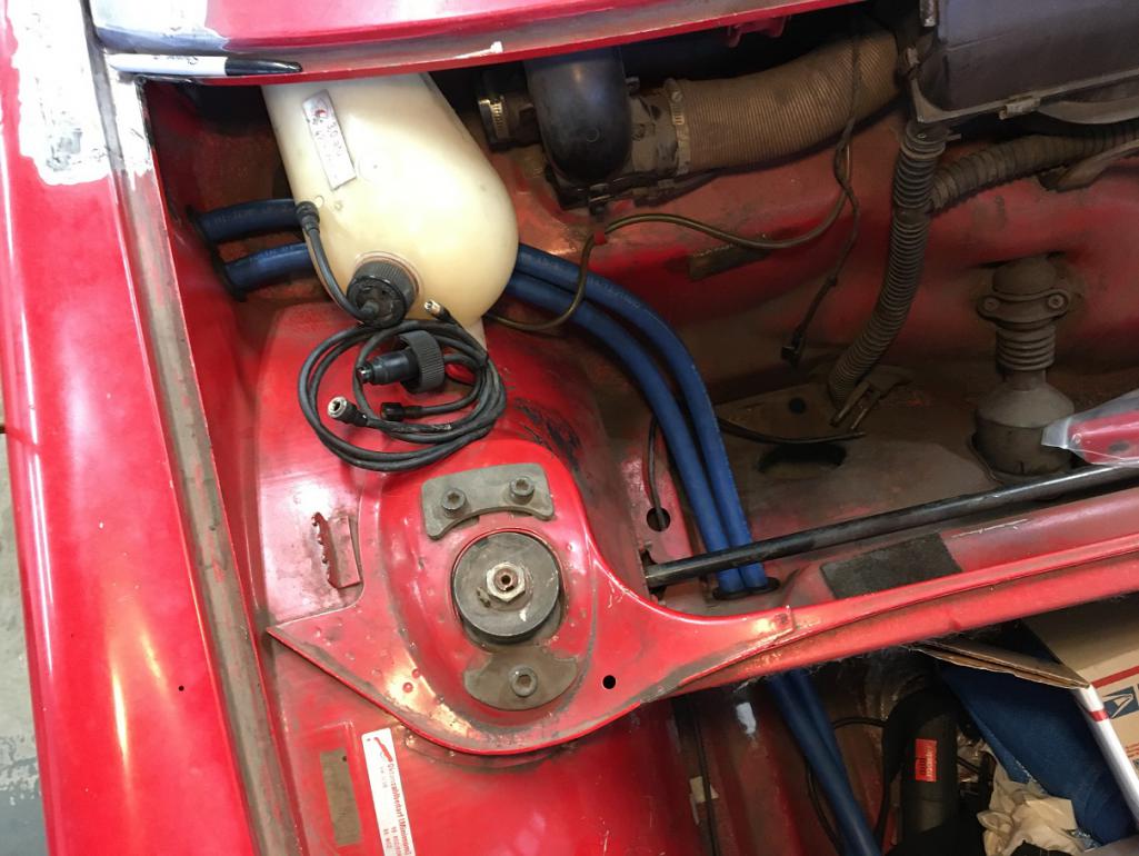
Upcoming next, the front oil cooler!
Posted by: bkrantz Dec 12 2021, 08:05 PM
Nice work--looks great!
Posted by: Montreal914 Dec 12 2021, 08:08 PM
I am using a Mercedes Diesel oil cooler I got from Bruce Stone a few years ago. There are at least 2 versions of their coolers that are normally mounted vertically to the driver side of the main radiator.
The one I will be using is the smaller one. The main reason is that I wanted it to fit under the arched structural shelf in the front of the car. The cooler came with the mating fittings which makes it convenient.
Using my trusted cheapo hack saw, file and vise, I fabricated a couple of brackets out of a 2"x2"x1/8" aluminum square tube.
The result is this: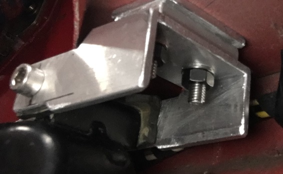
The brackets actually use the stock MBZ cooler mounting points. So the cooler gets attached to the front shelf, suspended from it. The only modifications made to the car at this point are four 1/4" holes in the shelf and the removal of the front rubber plugs. Noting that will weaken the front of the car.
Using a torch, I gently heated up the driver side cooler fitting to change its angle to get a smooth path for the blue hose (mock up with black hose here).
Also, since the car will be converted to 5 lugs, I am using a 4 1/2" wide Fake Fuch wheel with a small donut spare. The smaller diameter allows me to push the spare against the back end of the trunk while using the stock spare anchoring point but in one of the lug hole instead of the center of the wheel. This creates enough room for the air to exit from the back side of the cooler. Venting will be achieved through the round access ports in the back of the trunk floor. Finally, a new lower trunk floor will close tight and create the plenum for the air flow.
Result: Larger trunk space, inflated spare tire, and obviously an oil cooler. 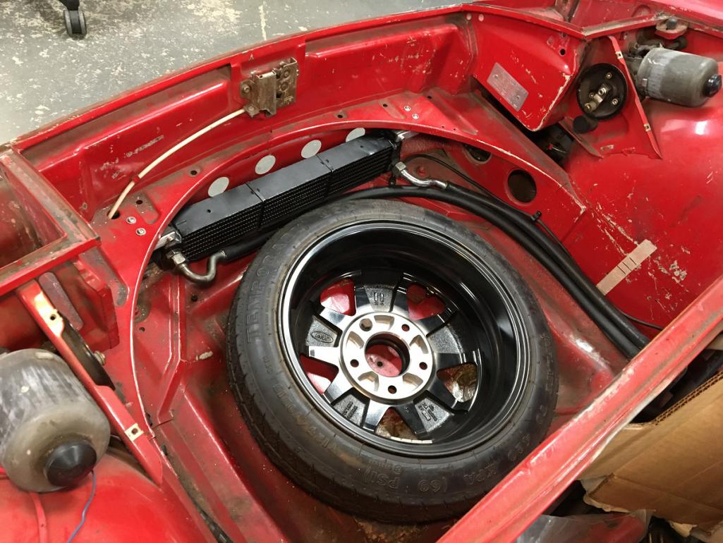
Posted by: pete-stevers Dec 12 2021, 10:09 PM
Inspiring thread! that is a job well done!
Posted by: Montreal914 Dec 12 2021, 11:33 PM
Inspiring thread! that is a job well done!
Thank you!
I get my inspiration from this forum!

In a way, sharing the progress is motivating.
Anyone who has been down this road knows that motivation can have its ups and down. I try to apply the wisdom a good friend once told me: "A little every day!", but it is not easy... Progress and knowing others here are in the same boat is definitely encouraging!
Posted by: Cairo94507 Dec 13 2021, 08:14 AM
Very nicely done. That should keep your engine nice and cool. I really like the hard lines you made - great work.
Posted by: Montreal914 Dec 15 2021, 11:36 AM
Here I will need the input from the experienced people!
My car has been hit in the rear driver side quarter at some point and this translated into an irregular curvature. Recently, I removed the bondo that was causing most of the hump, but as you can see in the pictures below, this was a half way straightening job of the fender.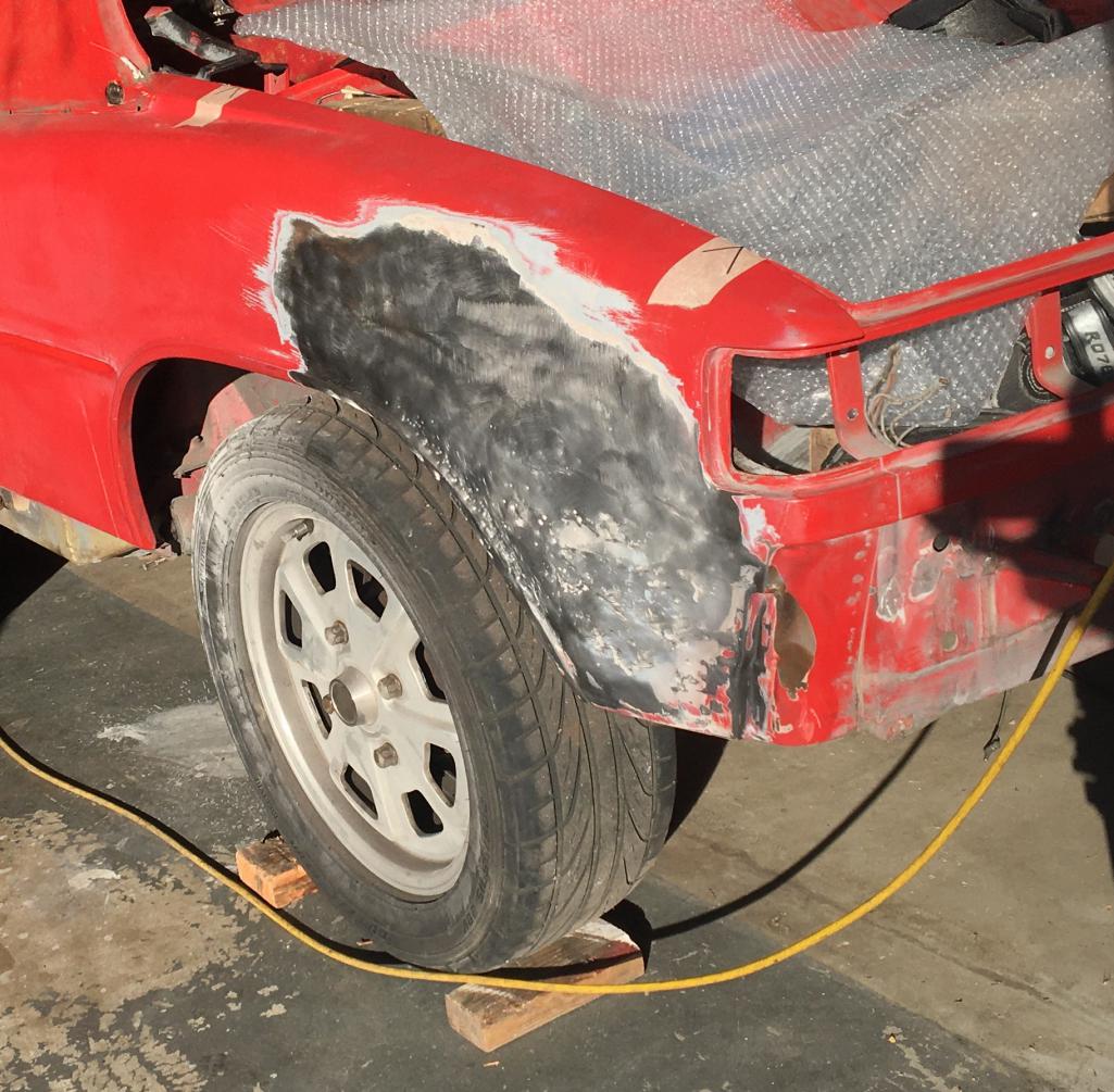
I am pretty sure this fender can be saved by the right qualified person (which is not me) but I fear the cost might be more than cutting and replacing, which is something I can do up to the level of work seen throughout this thread.
This is not a show car, it will continue being a regularly driven car with a fresh paint.
I do have a donner quarter I got from Bruce Stone. Unfortunately, it was cut a little shy on the back side but is probably manageable. Another option would be to get a whole fender from Vince and replace it but that involves dealing with the door, vent area, and sail.
So, should I get this fixed or should I cut and replace? If I do cut/replace, should I replace the whole fender to prevent the vertical scar in the middle?
Thank you for the inputs!
Posted by: Luke M Dec 15 2021, 02:34 PM
I've done both of these type of repairs. My brothers 914 did just that, section the rear q-panel. It was kinda of a pain to line things up just right. Took several tries but we did eventually get there. You can see where I cut and butt welded the panels together. Then cut for the flares. Getting the panels to mate just right is hard and it still doesn't look right. Bondo either way we look at it is gonna be the fix now. On my 6, I replaced the whole q-panel. It wasn't that much more work to do. Getting the panel off was the easy part. I cut off the panel then went back and removed the rest of the spot welds. Cut carefully in the targa area as you will cut into the inner support if you go too deep. If you can get your hands on a clean, rust free q-panel just replace it. Have you looked at your targa/door handle area yet? Mine looked great except it was filled with bondo over rust.
Attached image(s)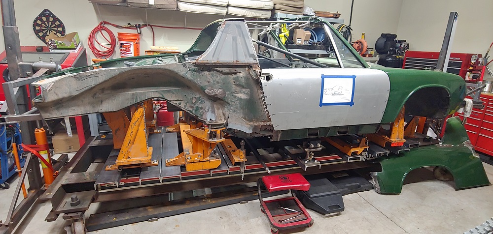
Posted by: Montreal914 Dec 15 2021, 03:27 PM
Thank you for the advice and pictures Luke.
My door handle and sail area is in decent shape. My fear of replacing the whole quarter is dealing with the tubular vent in the door jamb and all of door edge alignment.
I am sure I can get a good condition quarter that would be cut beyond the mating surfaces. I can clean it up to the mating surface making it a "new" part to install.
So, from the three options initially mentioned, the current recommendation is:
1- Replace whole quarter
2- Replace partial quarter
3- Straighten whole panel - not commented
Posted by: Luke M Dec 15 2021, 06:12 PM
Thank you for the advice and pictures Luke.
My door handle and sail area is in decent shape. My fear of replacing the whole quarter is dealing with the tubular vent in the door jamb and all of door edge alignment.
I am sure I can get a good condition quarter that would be cut beyond the mating surfaces. I can clean it up to the mating surface making it a "new" part to install.
So, from the three options initially mentioned, the current recommendation is:
1- Replace whole quarter
2- Replace partial quarter
3- Straighten whole panel - not commented
The vent tube is not that hard to deal with. If you can get a full q-panel have it cut with that vent in place. When you get it trim the metal off it. On the chassis you cut that vent out there's only 2 welds holding it in place. Clean up the area and the new/used section will fit right in. It was pretty easy to do. I used a spot welder to install most of the q-panel then mig welded the areas that I couldn't reach with the spot welder. Replacing the whole panel also gives you access to the backside of the targa. You can clean up and spray epoxy to help future rust in there. On my brothers car I used eastwood internal frame coating in all of the hard to get areas. If you never used that stuff it comes with a long hose and a nozzle tip that sprays in a pattern. It coats pretty well.
Posted by: Montreal914 Dec 15 2021, 08:14 PM
So am I understanding that you keep the tube on the donner fender and join it to the body inside the cabin here? I have seen in another thread that you simply grind off the edge weld to free up the original tube.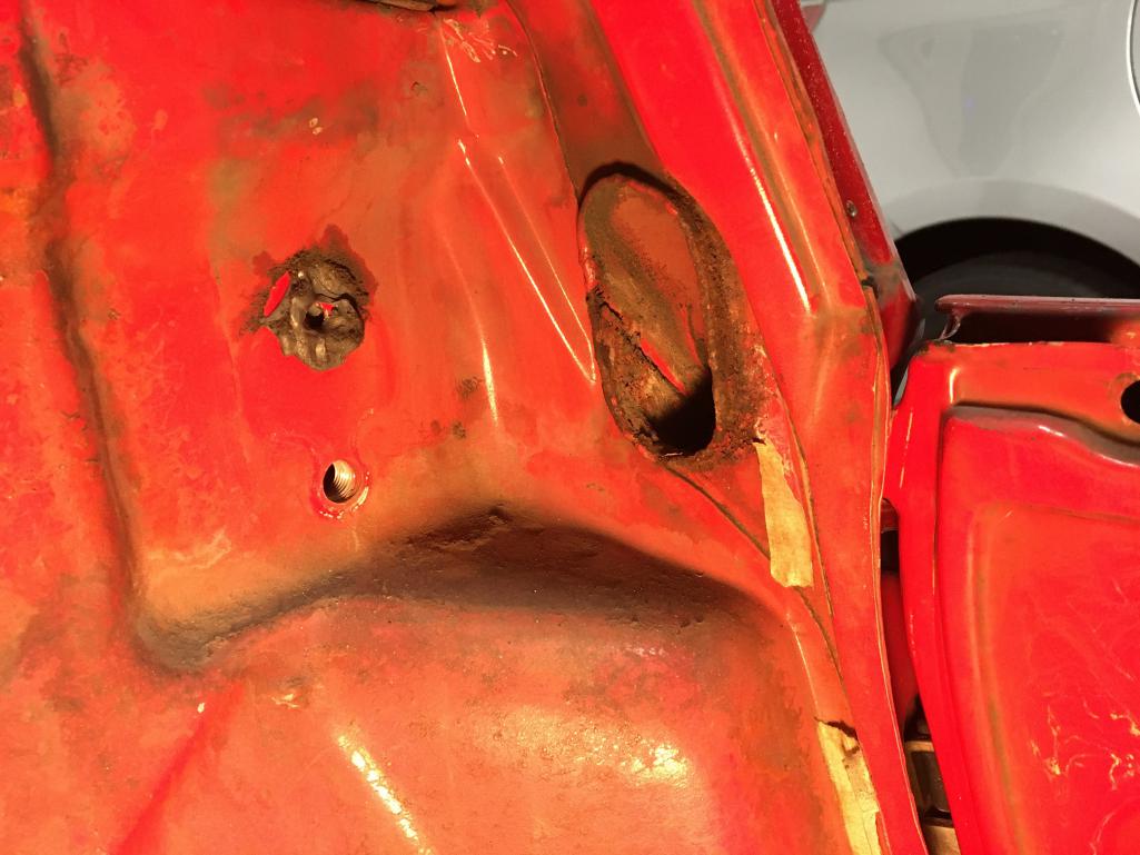
Unfortunately, I don't have a spot weld, this will be a MIG plug weld operation. Yes, having all of that section open will definitely allow me to inspect and protect. I do have a can of Eastwood with the tube, thanks!
Posted by: Luke M Dec 16 2021, 11:07 AM
Correct. Keep the tube on the donor q-panel. Remove your old one and clean up the mating areas. The new tube should slide right into place then you can see where everything lines up on the chassis. I'll snap a few pics later on my 6 as it's still apart.
Posted by: Montreal914 Dec 17 2021, 06:30 PM
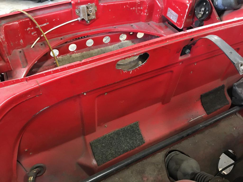
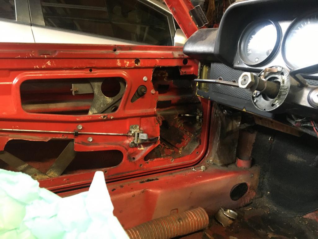
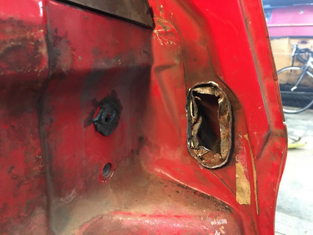
After removing the blower box and the wiper assembly, I have noticed this "custom" enlargement of an original hole about 5/8" dia. I notice there is one too at the same spot on the driver side.
Anyone knows the use of these hole?
My car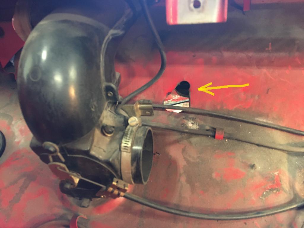
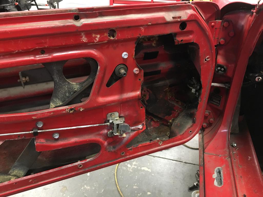
Another project car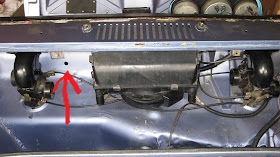
Posted by: Luke M Dec 18 2021, 09:37 AM
After removing the blower box and the wiper assembly, I have noticed this "custom" enlargement of an original hole about 5/8" dia. I notice there is one too at the same spot on the driver side.
Anyone knows the use of these hole?
My car
Another project car
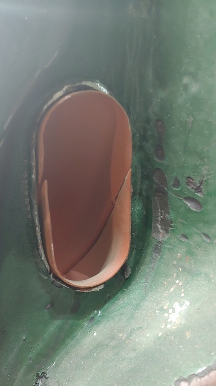
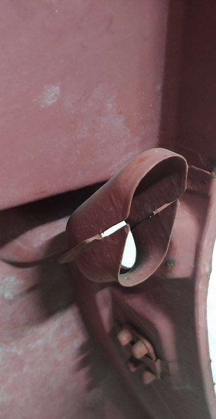
I believe that's for the antenna wire. Here's pics of the fender air intake from my NOS panel.
Attached image(s)
Posted by: Montreal914 Dec 18 2021, 02:45 PM
@http://www.914world.com/bbs2/index.php?showuser=3574 Antenna, humm seems like a good explanation.
Thanks! This is very clear now as to how to tackle the fender vent area. 
Those NOS panel...
Posted by: Montreal914 Dec 20 2021, 09:14 PM
A little progress this weekend. I delicately removed the rest of the ventilation system in the front trunk, i.e. the selector valves and diffuser. I did leave them connected together by the actuator cables in hopes of easing the process upon reassembly. I will probably take them apart though to see what needs rebuild. No picture, sorry...
I also plugged the two holes that had been done on the passenger side door for a stock mirror. Clearly, the person who did this wasn't aware that the threaded plate is behind the door metal and instead, simply drilled in the door skin.  No wonder why I was never able to tighten that mirror properly... In front of the now plugged holes are the ones I did a while back using a Dremel bit after drilling a 1/16" hole in the center. I took measurement references from the driver side door. Both of my 1/16" holes where close to the center void of the threaded plate. The rest was easy, carefully digging with a small burr.
Before: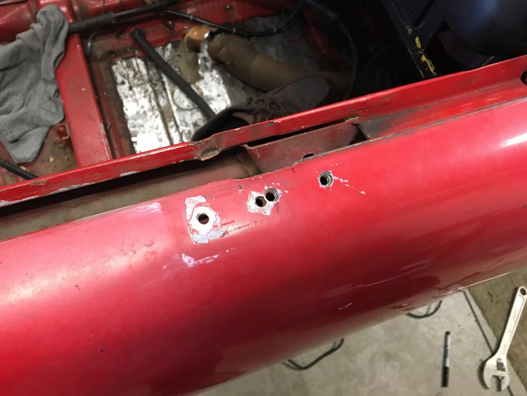
After: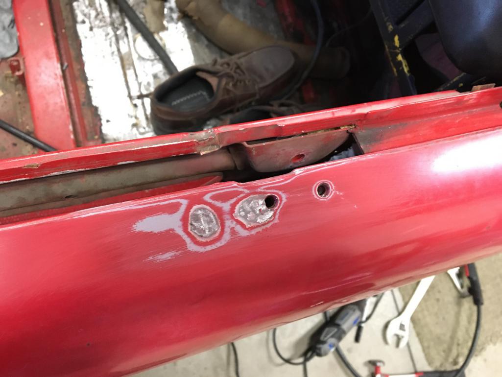
Finally, I moved on to finish the oil lines project. I fabricated a couple of brackets to support the front end of the aluminum rigid lines in the wheel well. Each bracket has an M6 nut welded on its back side allowing easy installation of the Abel clamp. Everything is now nicely secured. 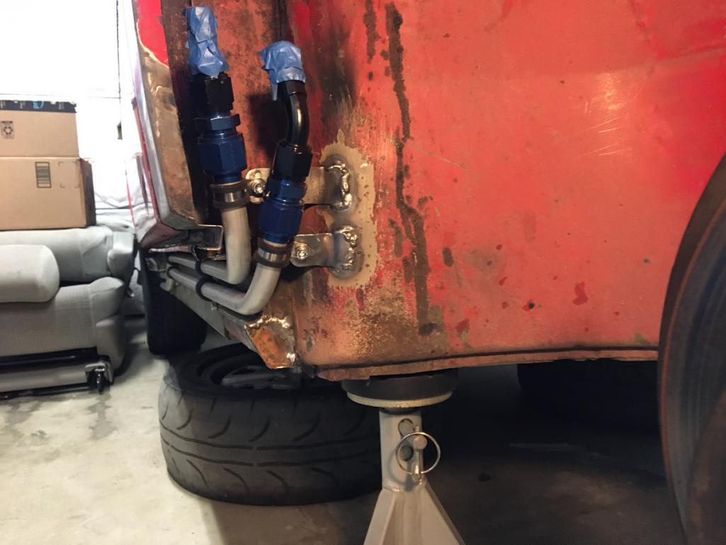
Posted by: Montreal914 Dec 23 2021, 05:16 PM
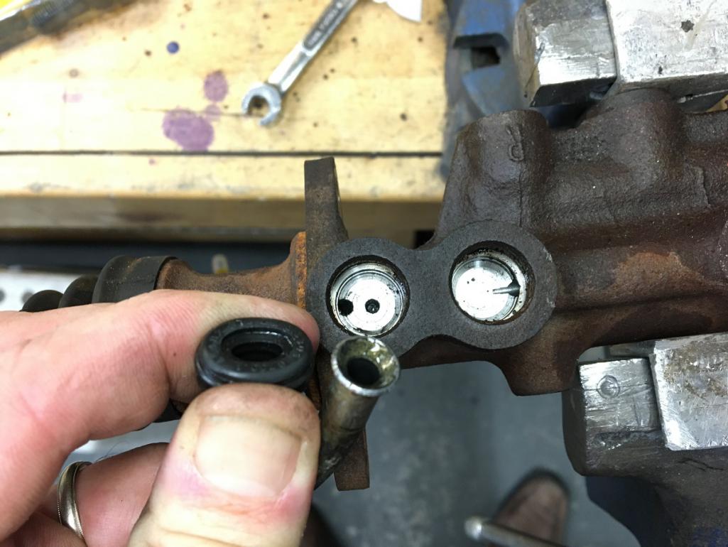
Today I removed the master cylinder and pedal assembly. This is a stock 17mm Ate. I removed all the parts from it in case I will need them on my new 19mm Ate MC once I reassemble the car. I will use a 19mm since I am upgrading to 911 front struts.
So, after removing the plastic/metal feed lines and grommet from the MC, here is what I am left with (picture). I thought there was supposed to be a washer underneath the rubber grommet?
I drove this car daily for 10 years and the MC was bone dry. I thought without the washers, the feed lines would leak? Do I have a different setup here?
I will check to see if my new 19mm MC has the washers but please confirm that I do need the washers under the rubber grommet.
Thank you!
Posted by: Montreal914 Jan 1 2022, 08:06 PM
Happy New Year!
Being stuck at home for the Holiday's, I had the chance to work on the fuel pump relocation. I went the route Porsche did for the 75-76 models. Having bought a pump panel a while back from Bruce Stone, this was the foundation for this little project. I also have all of the hardware to install the new 2 port Bosch pump.
New fuel pump assembly on my 75-76 panel 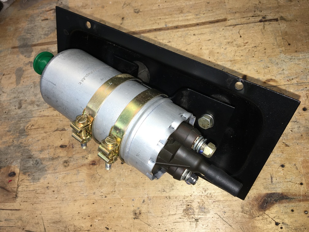
As mentioned, in 75 Porsche relocated the fuel pump to the front to eliminate the common fuel vapor lock issues that many of us have already encountered.
Below is a picture of a stock 75-76 setup. We can see the pump on the access panel, and the filter mounted on the opposite firewall. The fuel filter featured a tab on one of the mid plane ridges that would slide into the fork shaped bracket. Unfortunately these filters are very hard to find now. Since I plan on putting a lot of miles  on my car over the next 30+ years (hopefully), I want to use the readily available square filter which looks identical to the rare one with the tab, but without the tab.
Stock 75-76 fuel pump/filter setup: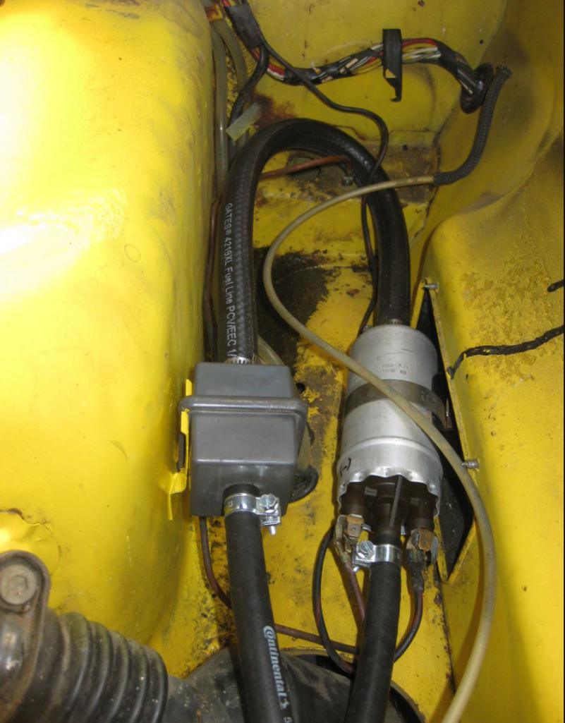
Hard to find 75-76 fuel filter: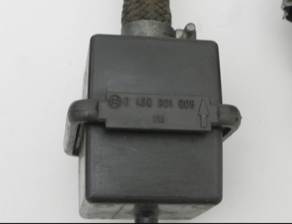
Based on Porsche's concept, I decide to removed the filter bracket located within the passenger side engine body mount as seen on the right side of this borrowed picture. I will recycle this filter mount and install it under the fuel tank.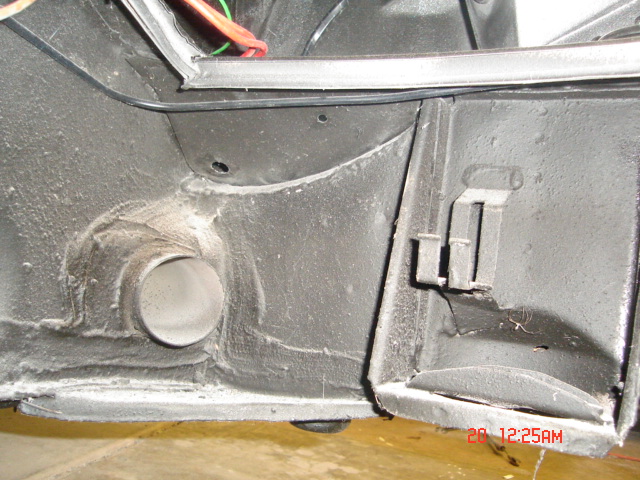
After cutting, straightening, and modifying the attachment points of the bracket, I tried my cheap and readily available square filter in it. Very nice snug fit, this will work as it was designed to work.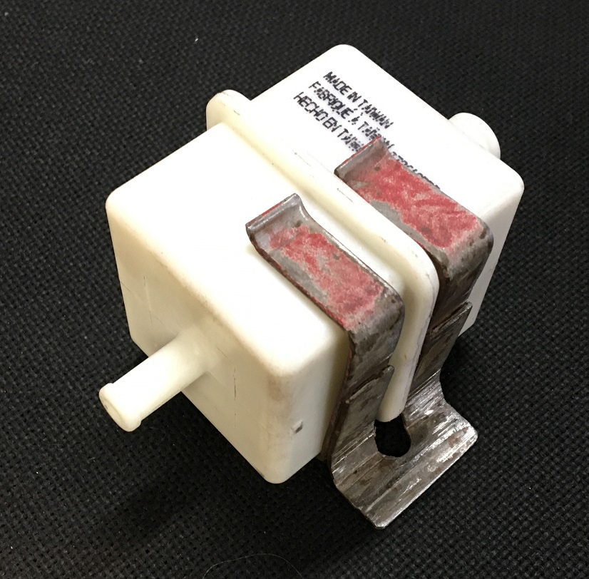
Now, on to the body modification. First step, establish the location for the 75-76 pump access panel and drill pilot holes in the firewall. Next, using a hole knockout tool, I generate the four corners.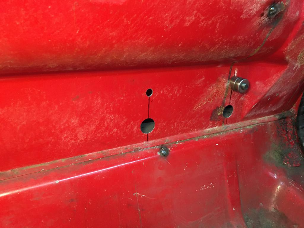
Then I cut the opening leaving about 1/4" metal to create a folded edge like the factory did, but not as nice though... 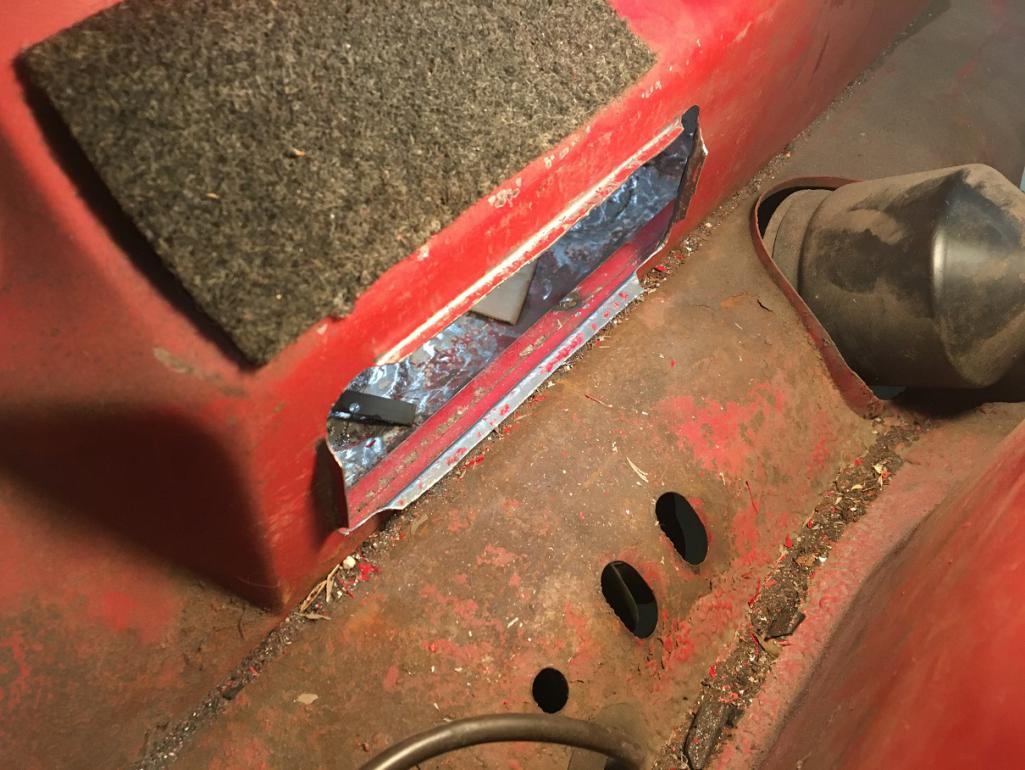
I should have kept material to create the folded corners but I thought it would be difficult to achieve in this tight area and without the proper tools. So instead, I welded in four strips to make the corners. Then I drilled the four holes and tacked M5 nuts to mount the pump access panel on the bulkhead. After some trimming and massaging, here is the final result with the pump access panel installed. The opening is pretty much the same size as the panel flange: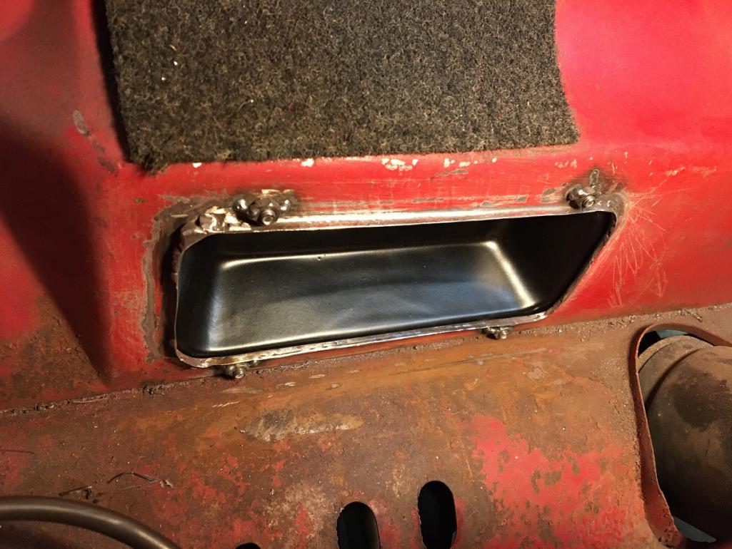
Trunk side view: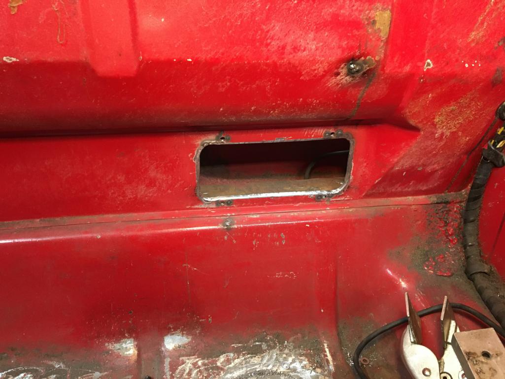
Last task, install the recycled filter bracket. Measure twice weld once... Using the new firewall opening, and installing the fuel tank back in, I carefully established the best location for the filter bracket, making sure there is enough space above the filter to remove it once the tank is in place.
Mock up before welding in place. Notice the edge of the black fuel tank running above the filter.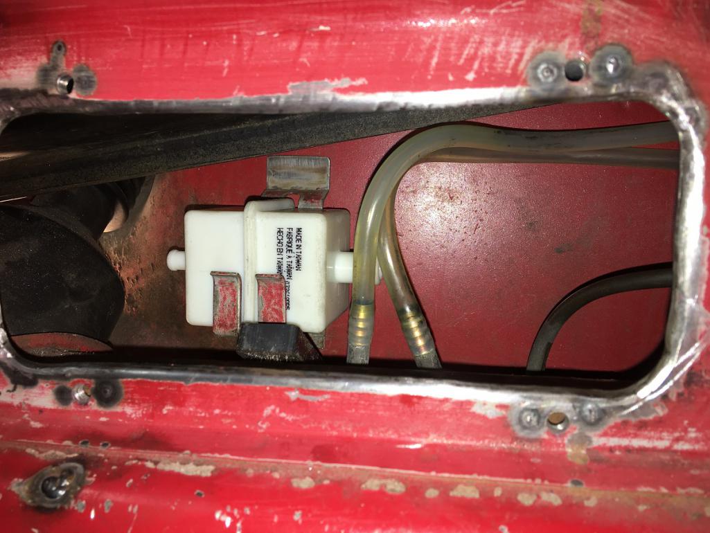
After fixing the filter bracket with a few tacks, here is the final result: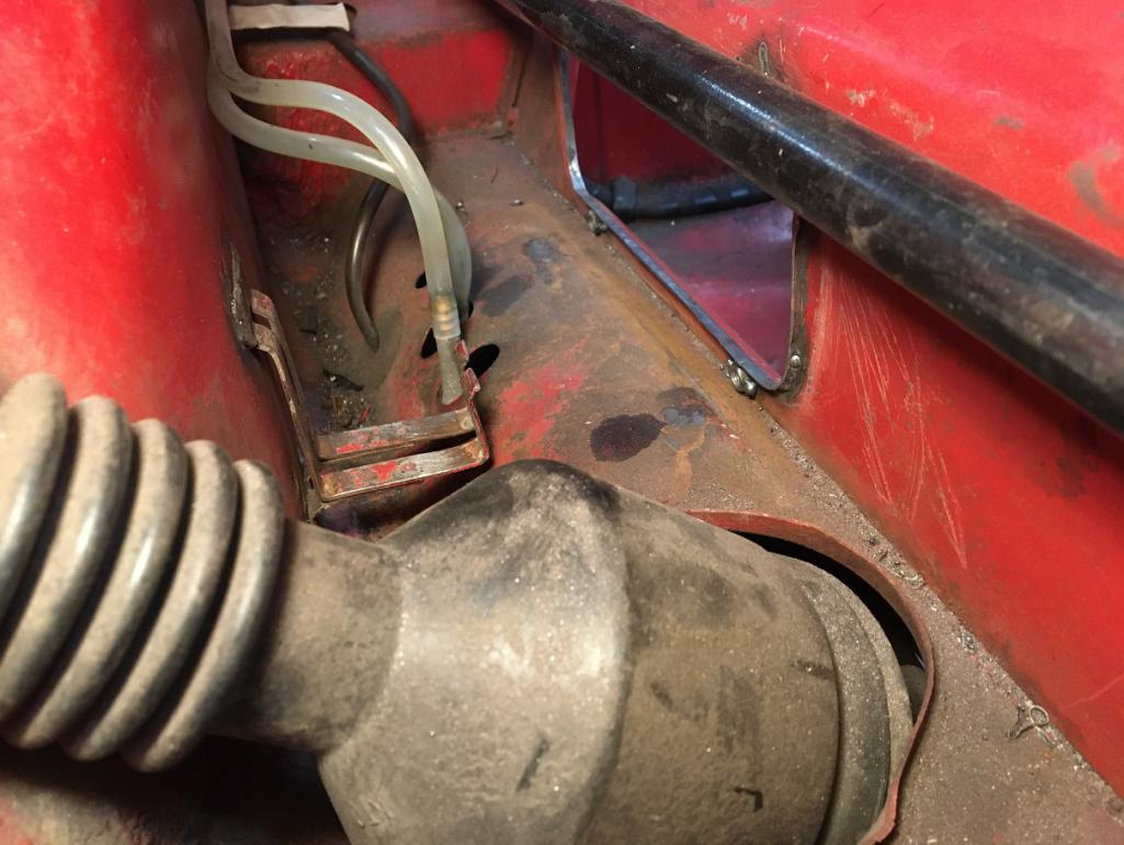
And now with the pump and filter in place:
[attachmentid=820867]
Another angle: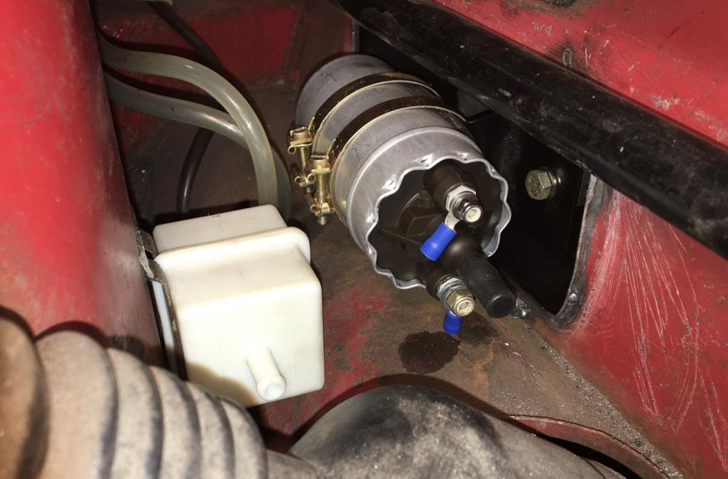
Front trunk view: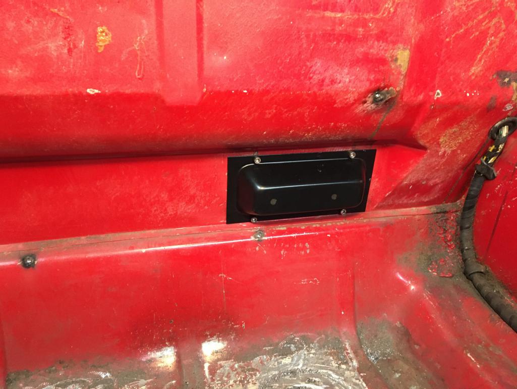
Another item crossed off from the list! 
Posted by: bkrantz Jan 1 2022, 09:32 PM
Very nice work!
Posted by: nivekdodge Jan 20 2022, 09:57 PM
Looks good Eric, let me know if I can help
Posted by: Montreal914 Apr 8 2022, 07:14 PM
Time to add some of the progress...
Believe it or not, my car upon previous ownership was equipped with an alarm system (ok), power lock  , and not one, or two, but three individual speakers in each door!
So below is the result of the bastardization done by one of these too many stereo shop that shouldn't be allowed working on ANY car... 
I guess the logical thing to do would be looking for a good set of doors, but who said restoring a 914 was a logical thing... Anyhow, for some reason, I preferred giving a new life to the car's original doors, than getting another set (don't try to find the logic )...
So in comes Bruce Stone @http://www.914world.com/bbs2/index.php?showuser=1319 to the rescue! Bruce had a set of heavily damaged door on the outside but un-messed with on the inside .
And so the patch work begins!
Donner door: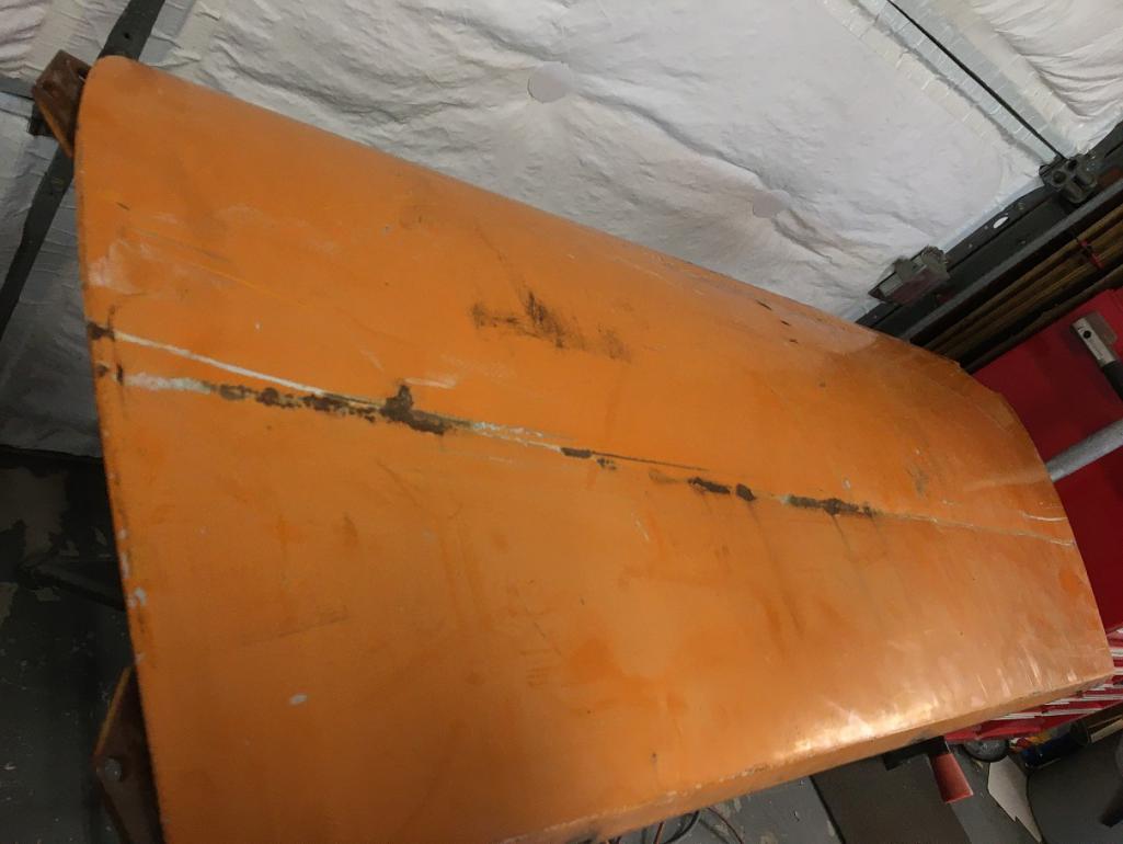
First step, repair the opening "created" for the power lock actuator. I cut that area out of the donner door while keeping half of the nearby holes as reference for positioning and prepping the car's door.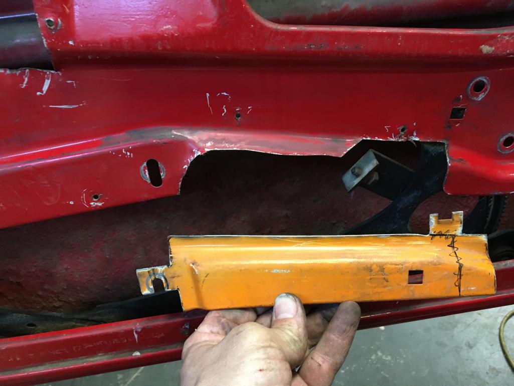
Seems to be fitting well!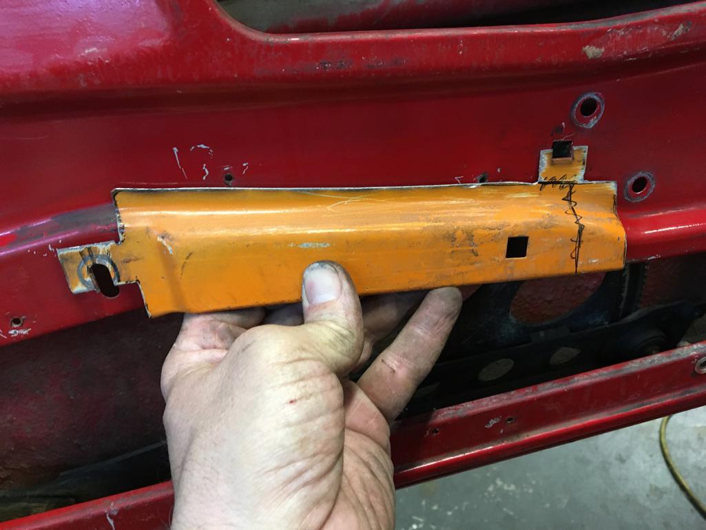
Now nicely cut the door to fit the piece.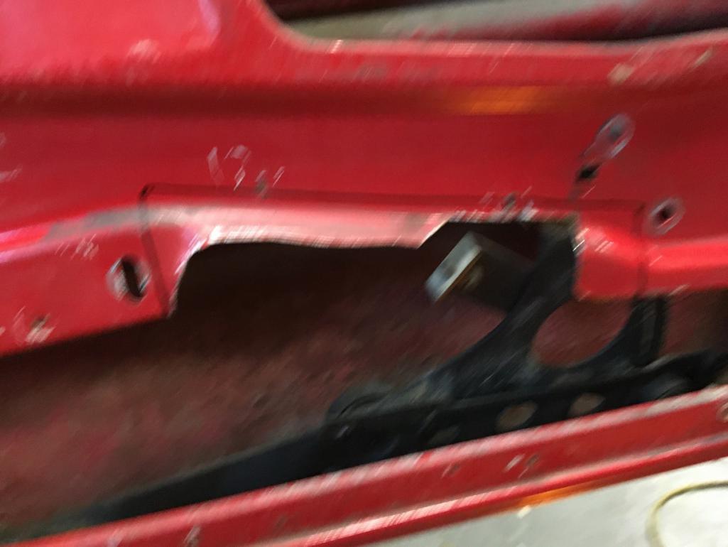
Finally, weld in place.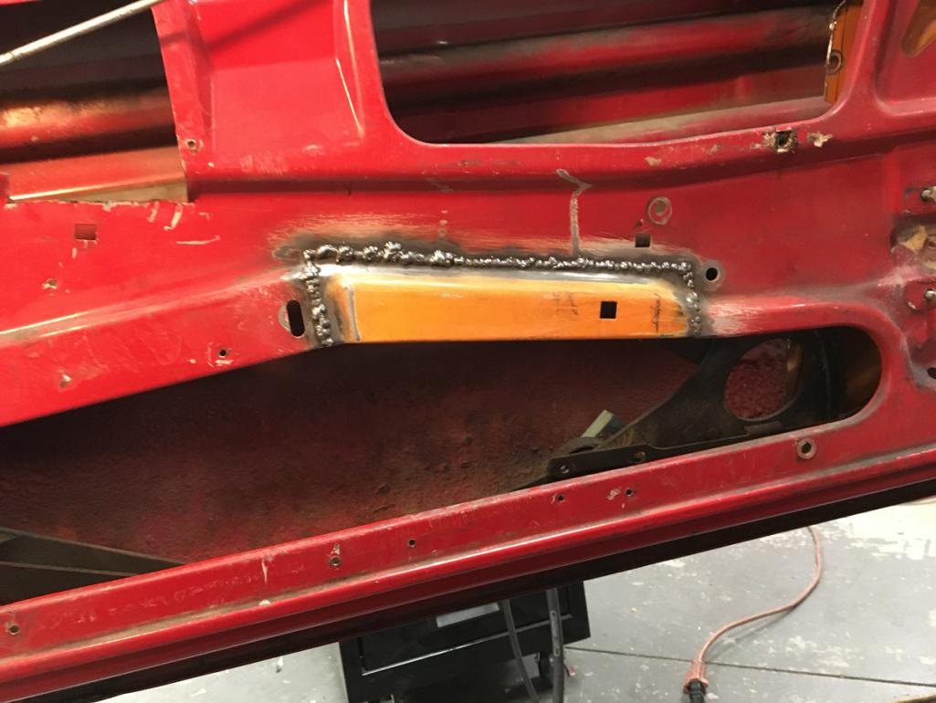
Now ready to tackle the large piece! Same concept, first cut a rough piece out of the donner door. Then trim down to what I wanted. Trace on the car's door and cut excess to make it clean, fit, once, twice, nineteen times... 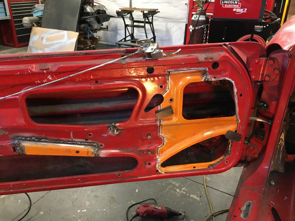
Then weld in place. Rince and repeat for all the areas and you get this! A door with character 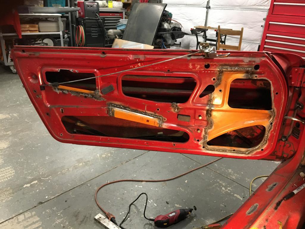
Next, the other door... 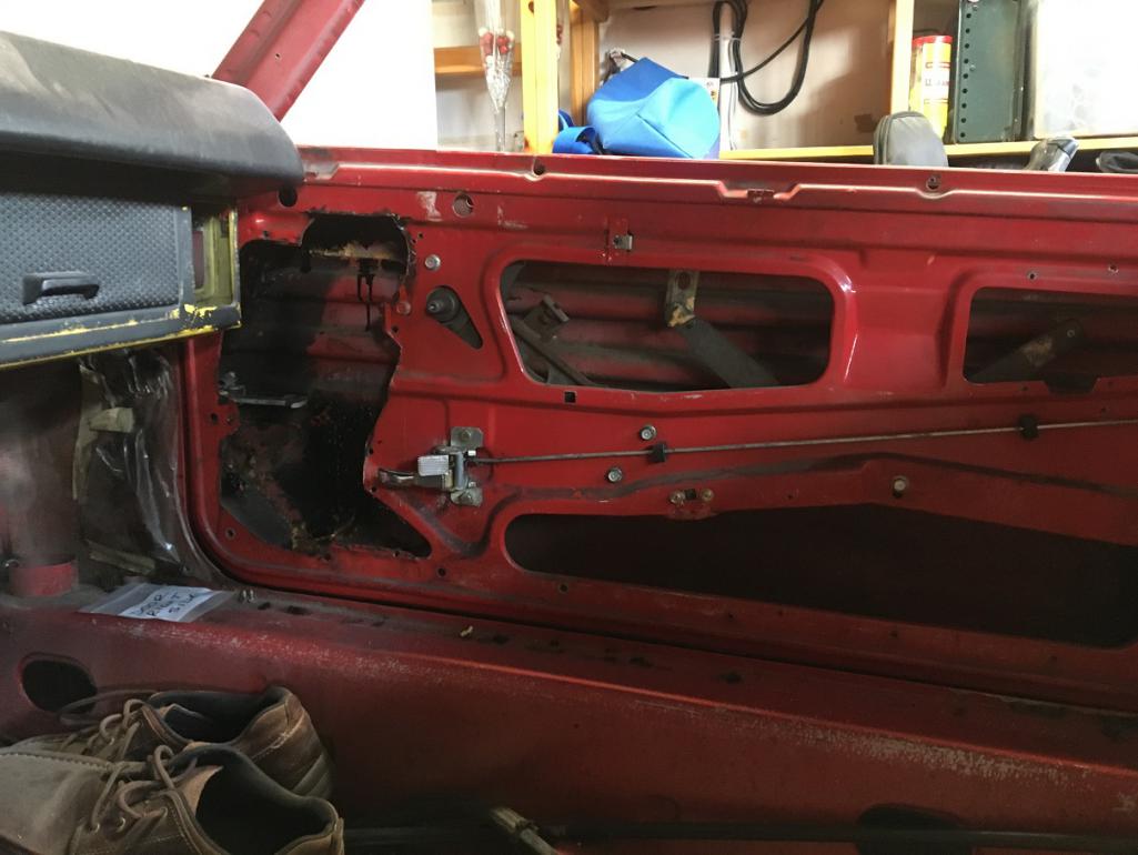
Posted by: nivekdodge Sep 24 2022, 06:53 PM
How are you coming along?
Posted by: Montreal914 Sep 25 2022, 01:01 AM
Thank you for asking! Clearly not as much progress as I would wish for. More house work got in the way...
But the passenger door got the same treatment as the driver's side one. 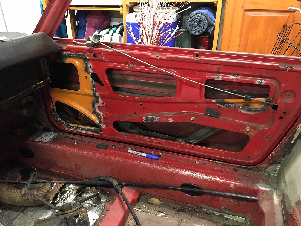
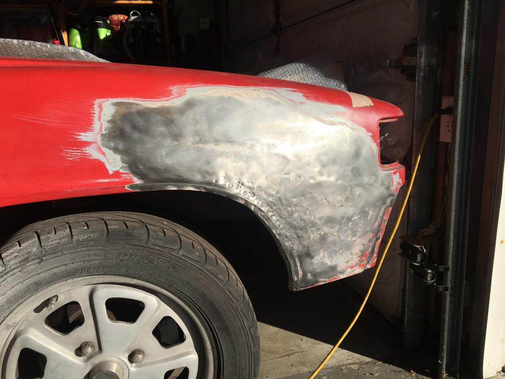
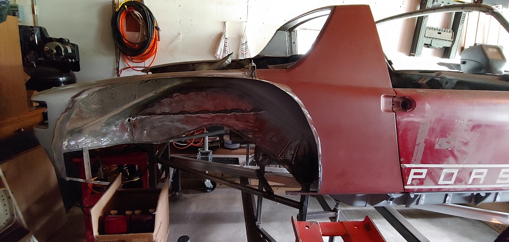
But now the next and hopefully the last major metal fix is the driver's side rear fender...
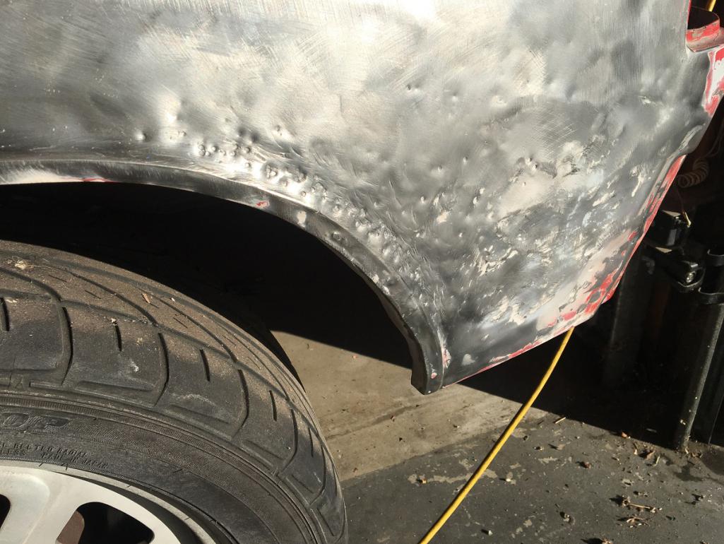
The car had been hit and poorly repaired in the past. Here is what I have to deal with. The rear part of the fender bulges out.
After removing the Bondo, not very surprising, here is what lies underneath. 
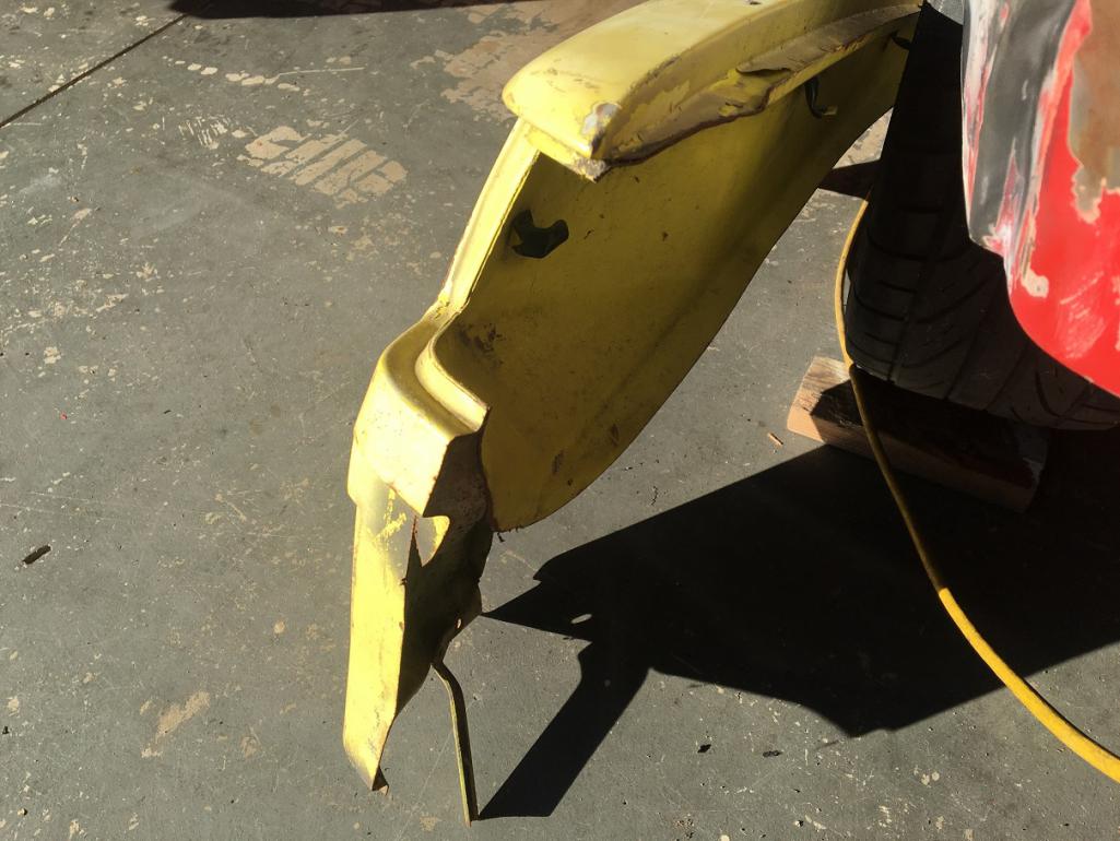
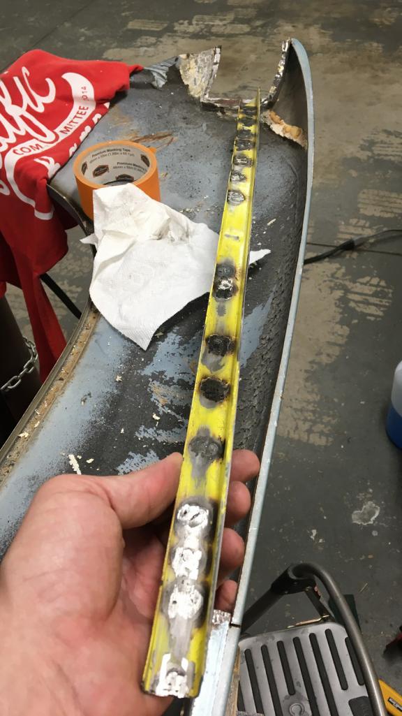
I have been looking at this for quite some time and have had a few recommendations as to how to tackle this. I have a couple of options: removing the rear half of the fender and fix it using this piece I got from Bruce Stone a few years back: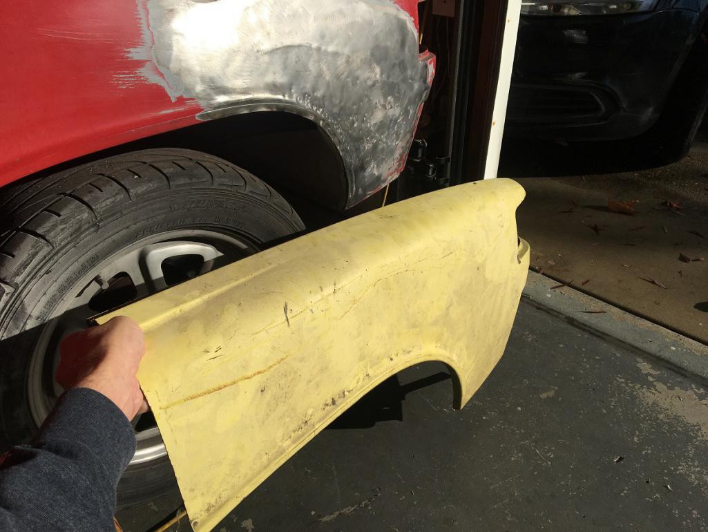
Although this might be a lesser intrusive surgery, I am very concerned at the vertical and other butt weld scars it would leave. I am working with a 120V Lincoln MIG with 0.025" wire, not a TIG welder, but most importantly, I am a beginner welder...
The second option which is a lot more work would hopefully keep the line of the rear fender.
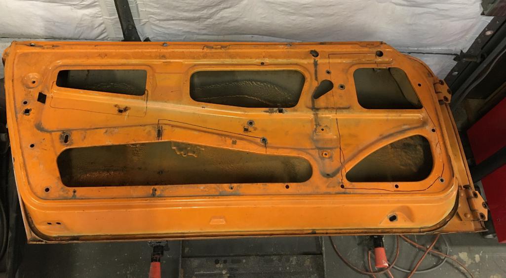
I got this whole dry and straight fender from Vince and I have been starting to prepare it for the swap. The fender is almost complete but has been cut short in some areas that I will need to be address. That being said, these are somewhat in hidden areas so should be more or less masked.
Here is the doner whole fender: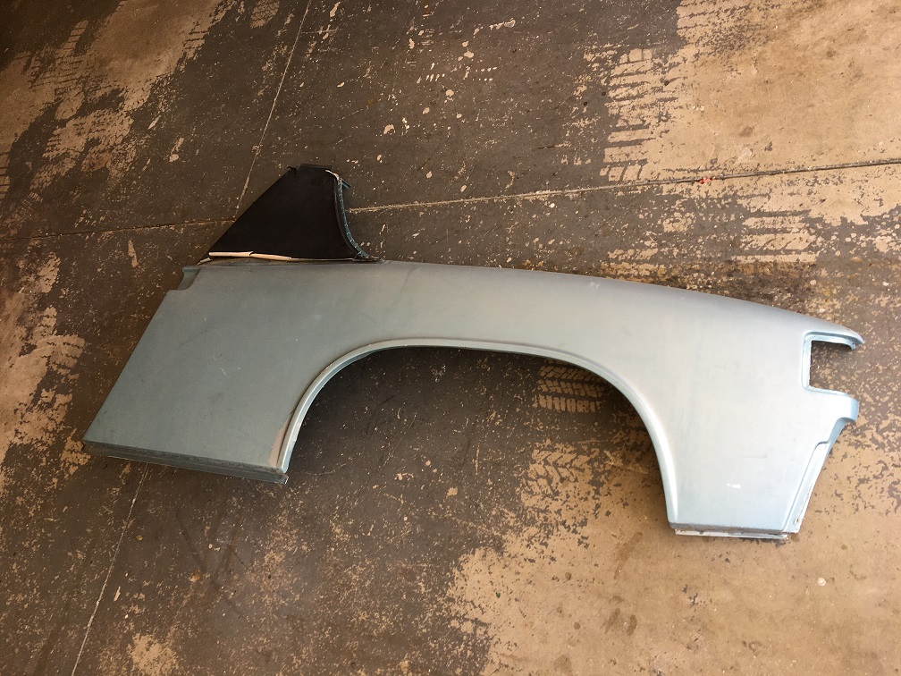
First area of some missing material:
And second area missing metal 
This means I will need to cut the car in the trunk seal gutter in the outer vertical portion and weld there.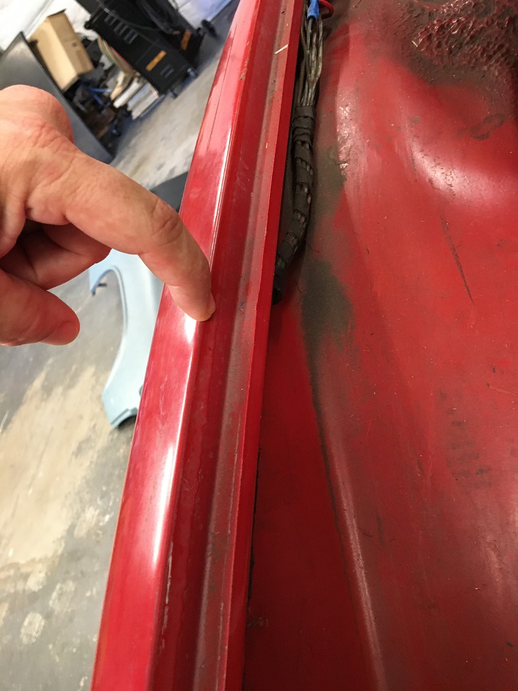
In the meantime. I have started preparing both doner parts the rear half yellow piece and the marathon blue fender. It is coming along but this actually more work that I expected. I drill through the spot welds in some areas, while I grind them down in others where I want the mating flange to be hole-less, all depending on which side I plan on doing the plug weld.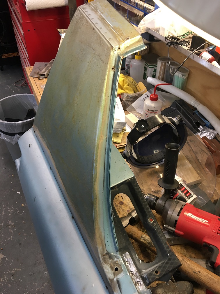
Finally the fender is almost relieved from the other parts 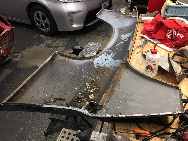
This corner was no fun to deal with...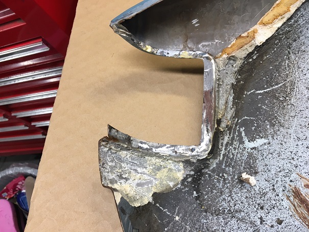
The work continues in the preparation of the donor parts. Still fully undecided as to which option to use, but I am leaning towards the whole fender replacement. I am definitely not looking forward to cutting the car's fender and prep the shell to match the "new" fender. There are a few zones that I can see as being tricky...
Posted by: nivekdodge Sep 25 2022, 07:57 PM
I think I'm still leaning to the whole fender also. The trickiest part will be the Trunk jamb. I would attempt to double flange it where you can. the strength will be better. There will be a lot of on-off- with the door and deck lid. the areas where the foam is I would clean and prime before install. Your welding skills seem more than accomplished enough to handle it
I'm stuck between FI and carb so don't feel bad.
Kevin
Posted by: Cairo94507 Sep 26 2022, 07:36 AM
Really nice work Eric. I agree with replacing the complete driver's rear quarter panel. The end result will be worth the additional work where it was cut short. Pretty soon all that rust and old damage will be a distant memory.
Posted by: Montreal914 Sep 26 2022, 08:14 AM
@http://www.914world.com/bbs2/index.php?showuser=25860 : By double flange you mean this classic assembly setup?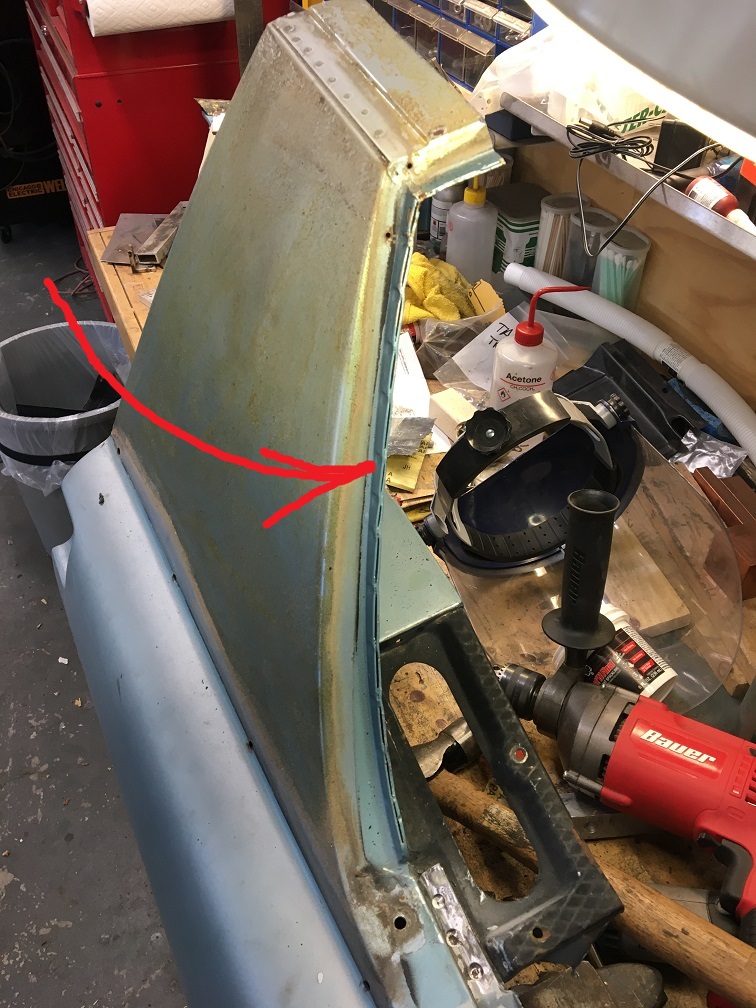
If so, yes that is the plan where the Marathon blue fender still has its flange. I originally was hoping to get a whole fender with all of its joining flanges but that was the best Vince had. Many passenger side fenders but that was the best driver side one. I hesitated a lot when purchasing it. The rear corner is a bit shot too and will require some thinking. I will post pictures of that area too when I get to the fitting part of the work.
I appreciate all of the help and encouragement, I knew this was going to be a journey, and I am really looking forward to the end of the metal repair segment of the restoration.
Posted by: nathanxnathan Sep 26 2022, 10:45 AM
You know my original advice was to splice in just what you need, but if you do end up doing the whole fender, I would drill out the parts that the donor fender needs from the car and patch it on the bench.
Spot/resistance welding the donor in would be so much easier than plug welding. Every seam of it is spot weld-able except the top of the targa bar. If you want I could come by with my spot welder some weekend — if you have everything prepped and fit up/clamped, the whole thing would only be a few hours. PM me if you want to — seriously soo much easier — and easier to make it clean than with a mig.
Posted by: Montreal914 Sep 26 2022, 11:20 PM
You know my original advice was to splice in just what you need, but if you do end up doing the whole fender, I would drill out the parts that the donor fender needs from the car and patch it on the bench.
Spot/resistance welding the donor in would be so much easier than plug welding. Every seam of it is spot weld-able except the top of the targa bar. If you want I could come by with my spot welder some weekend — if you have everything prepped and fit up/clamped, the whole thing would only be a few hours. PM me if you want to — seriously soo much easier — and easier to make it clean than with a mig.
Nathan, yes I still have all the pictures you sent me and did like the "simplicity" of cutting and replacing only what is damaged. That being said, I am very worried about the scars.
If I understand what you are saying, you recommend I make the doner fender whole using parts from the car. Actually, I believe with the yellow fender and other loose body parts I could complete the doner fender before even cutting the car.
Now, as for your spot weld idea, that is quite an offer!
 What kind of voltage is required for this 110 or 220V?
I am getting more and more confident about this challenge. I will continue the prep work and keep you posted.
Posted by: nathanxnathan Sep 27 2022, 11:39 AM
Nathan, yes I still have all the pictures you sent me and did like the "simplicity" of cutting and replacing only what is damaged. That being said, I am very worried about the scars.
If I understand what you are saying, you recommend I make the doner fender whole using parts from the car. Actually, I believe with the yellow fender and other loose body parts I could complete the doner fender before even cutting the car.
Now, as for your spot weld idea, that is quite an offer!
What kind of voltage is required for this 110 or 220V?I am getting more and more confident about this challenge. I will continue the prep work and keep you posted.
It's nice that you can build a complete fender without what's on the car. That means you can grind the spot welds and leave what remains on the car undamaged, and save having to fix any holes etc.
Ah yeah I was thinking about what sort of outlets you have. My Spot welder is a Miller LMSW-52 which is 220 single phase with a 20 amp Nema 6-20P plug with a pretty long cord. I do have an extension cord that goes from the 6-20P to a Nema 6-50 which is what I have in my wall for my Synchrowave, but that's probably not going to help. It wants a 20 amp plug so converting to a 15 amp dryer plug isn't a great option.
https://www.millerwelds.com/-/media/e50208051cc3492c9016790b303abf4f.pdf
I do have a nice variety of tongs which are actually pretty hard to come by. The "standard" ones, the TT-9's, and the FF's shown in the spec sheet above. I've got more into the tongs than I do the welder — it's crazy what they go for. I don't know if you need anything special for tongs, possibly for the tail light area the FFs would help.
I was looking at the 110v spot welder that Harbor Freight sells. If your plug/breaker situation is no good for 220v, it could be a good option. It's really low cost compared to what the miller stuff was.
https://www.harborfreight.com/120v-spot-welder-61205.html
Let me know what you think. I'm happy to help.
Posted by: 930cabman Sep 27 2022, 11:59 AM
Really nice work Eric. I agree with replacing the complete driver's rear quarter panel. The end result will be worth the additional work where it was cut short. Pretty soon all that rust and old damage will be a distant memory.

Will give you the best odds of a long lasting good repair
Posted by: Montreal914 Sep 27 2022, 08:03 PM
All good inputs!!
@http://www.914world.com/bbs2/index.php?showuser=21899 I have a drier outlet nearby not sure if this could work. But I have another option too , the shell is still a roller, even better, it is registered and insured, and to top it off, it has the tow bar bracket on and can be pulled by the family minivan. And yes the drive shafts have been removed and the stubs put back in to save the rear bearings.
Posted by: nivekdodge Sep 27 2022, 08:18 PM
Eric
I meant in the gap beside the trunk lid. I would leave the bottom of the original and add the replacement to it as much as I could
Kevin
OOps loooking now you dont have the bottom
Posted by: nathanxnathan Sep 28 2022, 11:31 PM
All good inputs!!
@http://www.914world.com/bbs2/index.php?showuser=21899 I have a drier outlet nearby not sure if this could work. But I have another option too
, the shell is still a roller, even better, it is registered and insured, and to top it off, it has the tow bar bracket on and can be pulled by the family minivan. And yes the drive shafts have been removed and the stubs put back in to save the rear bearings. The drier outlet probably isn't the best option as they're rated at 15 amp. The spot welder only has 1 setting. Each weld only takes about a second, but it's fully onm, and may trip the breaker...
That seems like a good option, if you can get it here for the day/a few hours. I can totally make space right in front of my studio as my project is mobile now on the rotisserie/dolly.
Depending on how together it is when you bring it, it might be pretty quick — spot welding is really nice that way.
Let me know if you need help with anything. I have a pretty decent number of c-clamps, which this sort of stuff always needs.
I would use 3m weld-through primer on both sides for the spot welding.
You'll want to look into what others have used to do the seal which is at the base of the sail panel. The fenders I have taken off it is a foam seal — which seems pretty bad like it would trap water. Is there some better, like rubber/adhesive option? I was thinking maybe 3M NVH Dampening Material? — it's an adhesive gap filler that is often recommended to bond like hood and door skins to their frames.
I was thinking about what I said, about the top of the targa being the only area you can't spot weld. This is I think true. I was thinking though about how the factory attached the front/lower of the inner/door jamb to the sill panel. They actually braze it, like with a torch and bronze there. I guess capillary action allows the bronze to flow between the 2 layers which overlap quite a bit. I don't have an oxy acetylene torch unfortunately, and I've never done it. I guess we could spot weld there as well. Maybe someone else has input on joining that area. maybe I'm overthinking it?
Posted by: Montreal914 Sep 29 2022, 06:53 PM
I would probably attach the fender using a few self tapping screws. Yes the surfaces would be weld through primed.
Jamb, I was simply thinking of mig welding it. Spot weld will not be an option as I have a Brad Meyer panel that will not allow to reach the actual back side of the sill where the jamb comes tangent to it.
As for the base of the sail panel, everywhere Karmann sprayed on or applied any kind of goop, rust tends to be there. I am not sure I would even want to seal the sail area. Sealing also means trapping moisture that could make it though. This car will be in SoCal and rarely seeing the rain.
I really appreciate your help, and feel more comfortable in bringing the car to your known working environment vs running into issues at my house.
I will keep you posted with my progress. This should still take a few weeks, I work slow...
Posted by: nivekdodge Nov 8 2022, 08:16 PM
I removed the tubes and almost welded the holes up solid. Hopefully no one closes the doors together.
Posted by: Montreal914 Dec 4 2022, 12:45 PM
OK, time for some update. The current work is focused on preparing the donor fender to make it whole again before removing the damaged one from the car.
A couple of areas will need attention. The first one I have been working on is the gutter area where the trunk seal lives. As shown before, unfortunately that area was removed during the fender's salvage yard days. I actually hesitated a week before getting this fender but the rest of its condition made me get it and deal with this down the road. 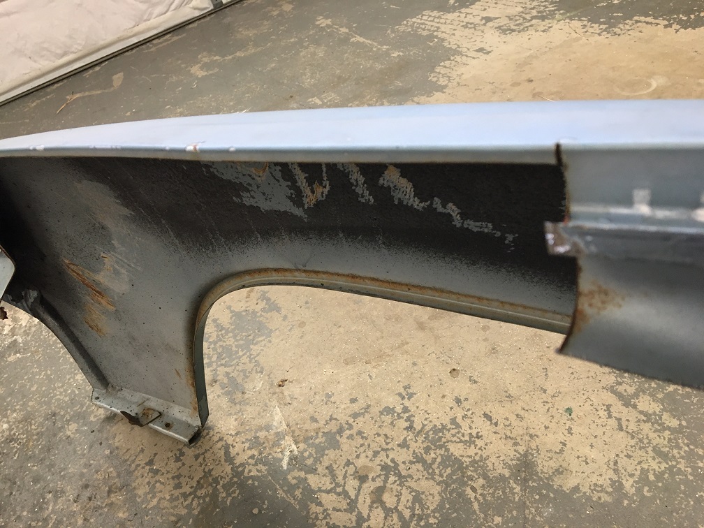
Using the yellow rear fender portion I have, I first removed the gutter section by cutting near the bend of the exterior surface so I can line the yellow piece over the new (old) fender.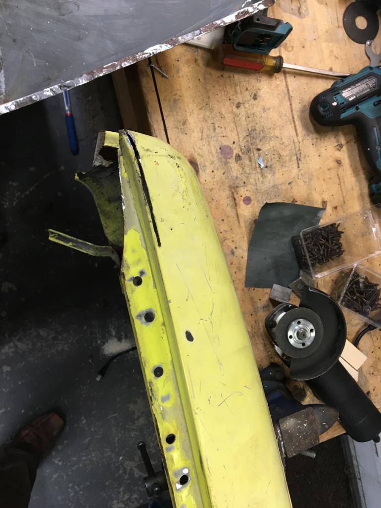
With both parts nicely lining up, I was able to trace on the yellow piece where it should be trimmed.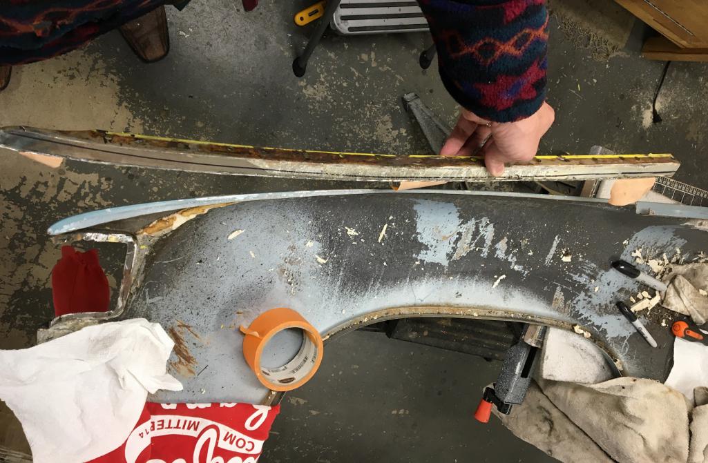
But before trimming it, I decided to plug the holes I had previously drilled out when preparing this fender section as one of my potential option for this whole fender repair. That was before @http://www.914world.com/bbs2/index.php?showuser=21899 's very kind offer of using his spot welder for the installation. I had originally planned on plug welding the repair sheet metal in place. So now I need to plug all these holes back! 
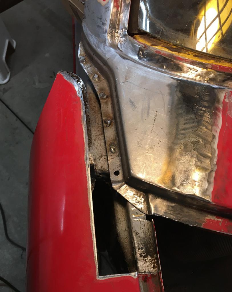
After trimming and removing the paint for welding. I positioned the piece using magnets. 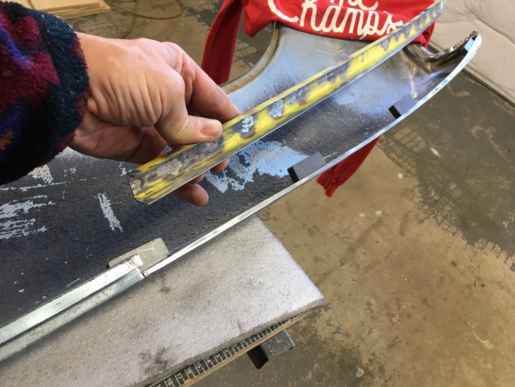
Measuring on my car, I established the depth of the gutter at about 19.5mm, so before putting any tacks down, measure three times, and weld! 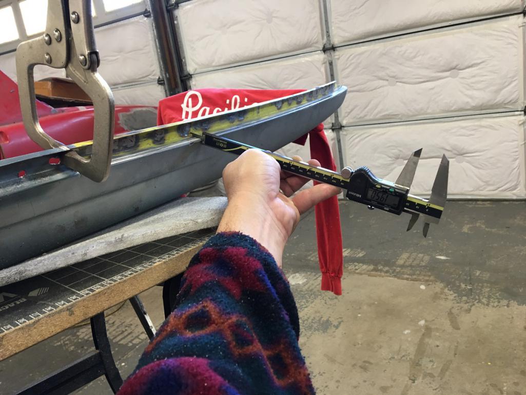
Current state of fabrication! 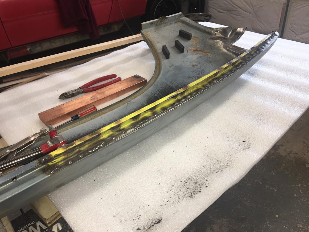
Posted by: Cairo94507 Dec 4 2022, 03:48 PM
Very nicely done.
Posted by: nathanxnathan Dec 4 2022, 07:35 PM
Lookin' good @http://www.914world.com/bbs2/index.php?showuser=12023
Posted by: nivekdodge Dec 4 2022, 09:04 PM
Yes it does, it looks great! make sure to clean and sand or even prime tha before you put it on
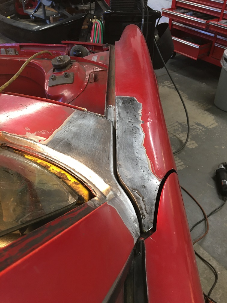
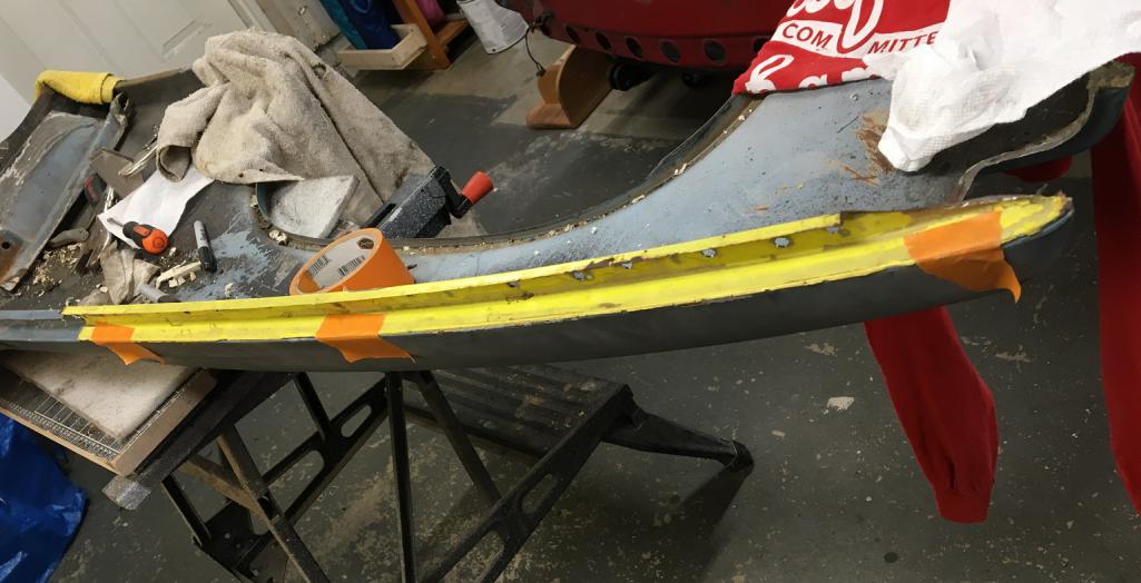
Posted by: Montreal914 Dec 17 2022, 05:43 PM
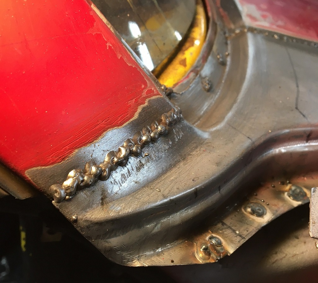
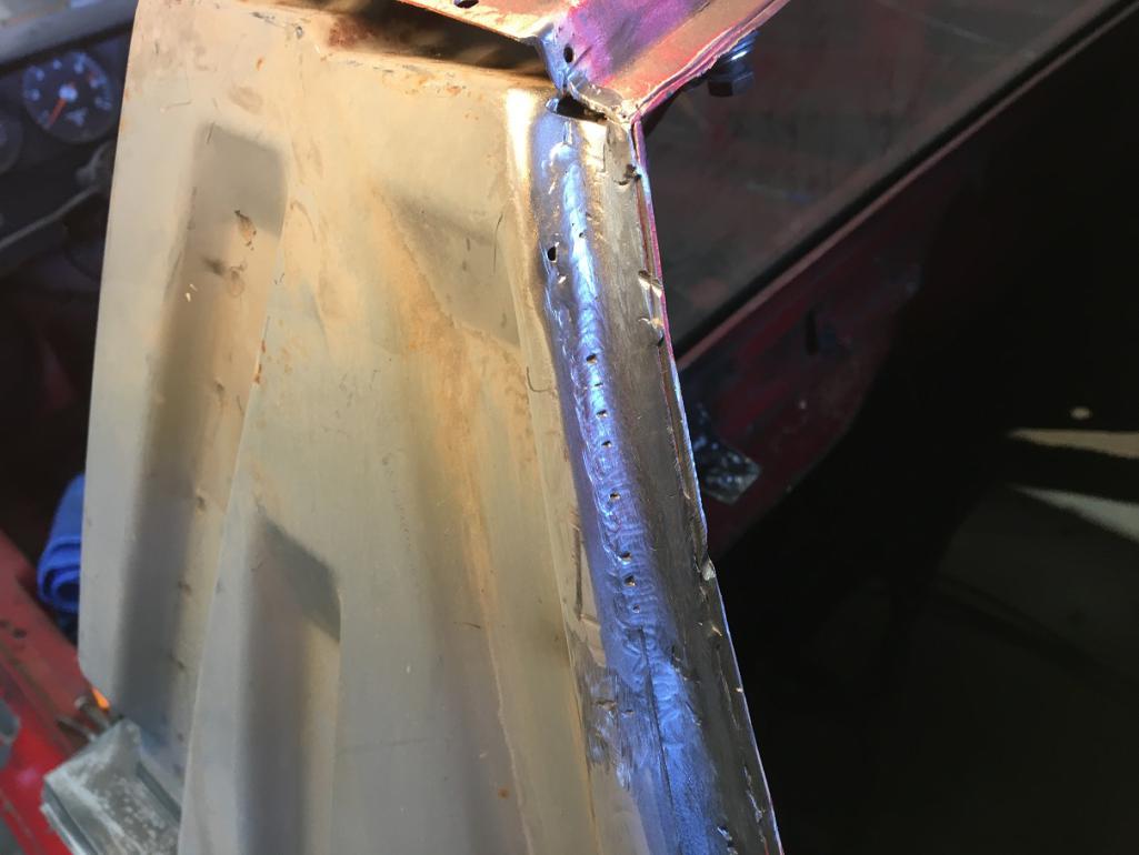
I was able to continue the slow process of making one stitch at a time while cooling everything and moving around. Eventually, I closed all the gaps. 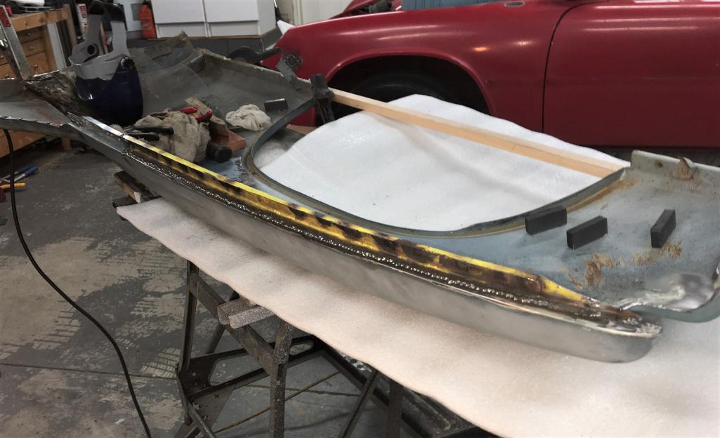
Then, time to grind down this long string, still trying to keep the metal cool with a wet towel stuffed in the back. Finally got to this.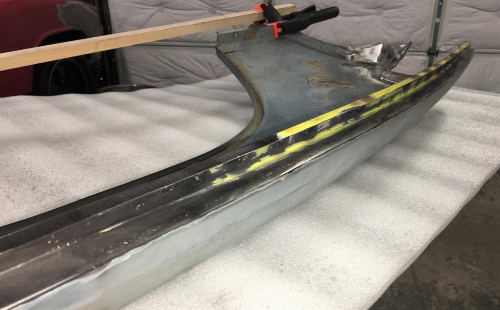
Another angle.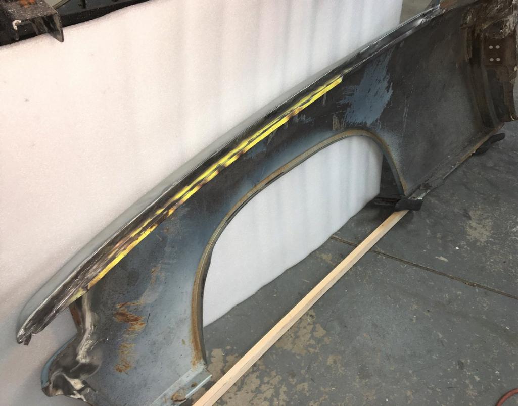
And just to make sure everyone understands... 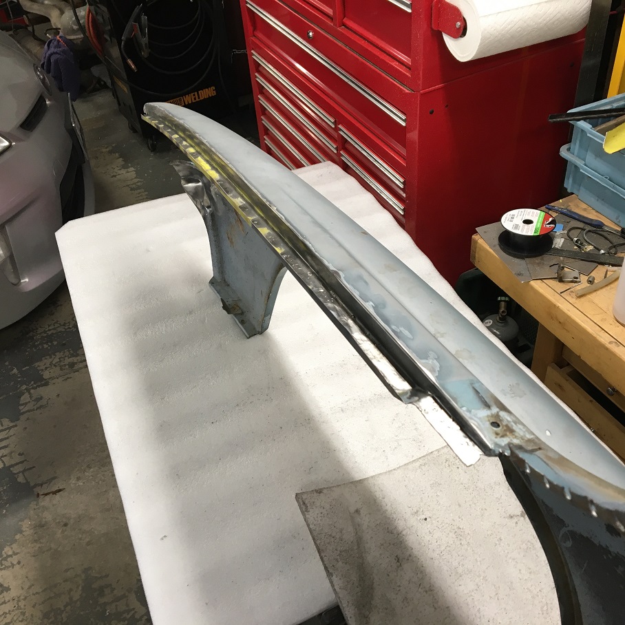
Needless to say that the fender is a lot stiffer now on its tail end. I think this area is pretty much done with metal work.
Now moving on to the other area needing attention before I can start thinking about installing this donner fender on my car.
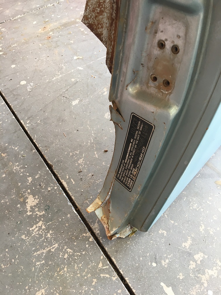
As shown before, the lower part of the door jamb was unfortunately cut where the fender mounts to the body. 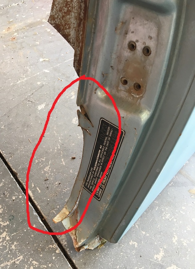
Luckily, when purchasing the fender, I was able to get this lower door jamb from another wreck. 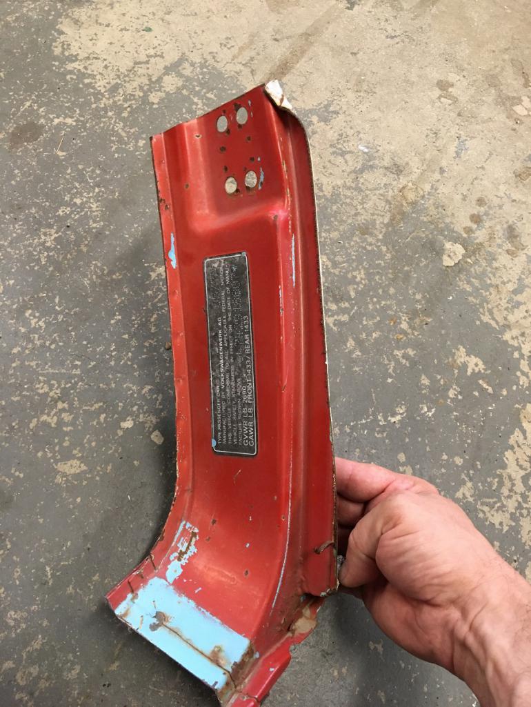
Time to remove the non-needed extra metal 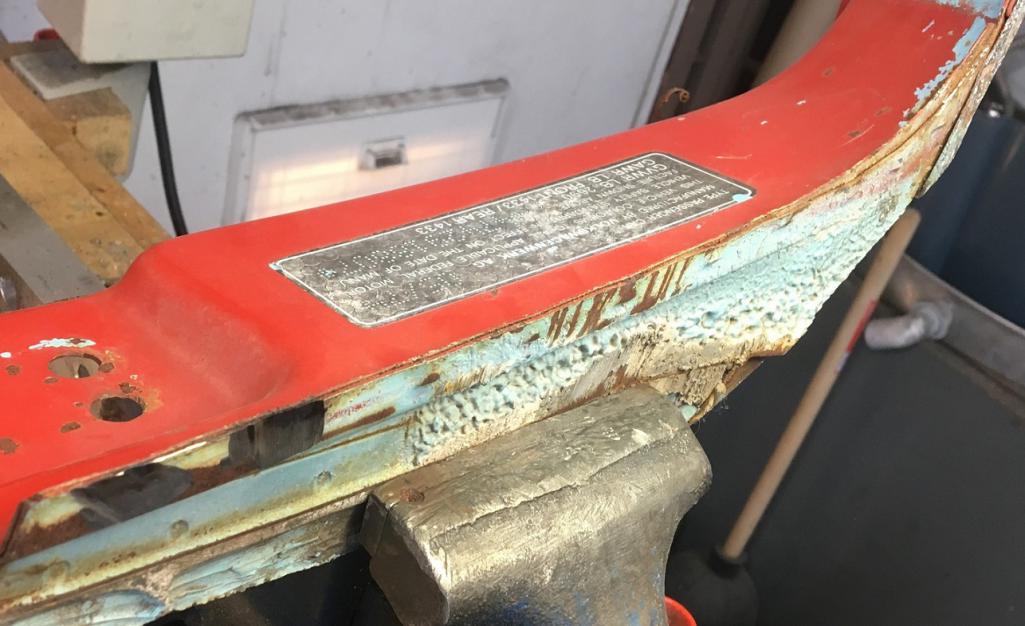
Now the part can be used.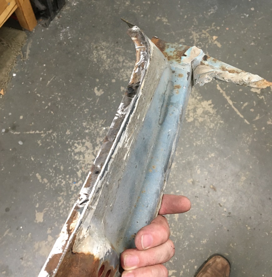
Here both the "new" door jamb area and the fender have been cut to be put together. The idea was to have a good portion of the jointed area to be hidden behind the VIN decal ( that I need to get...). You can also see the template I traced on the thin sheet of wood from the the car as a reference. When welding the repair piece in, the fender flange will lay flat on a 1/2" aluminum plate that is underneath. This part of the car being straight (vertical door jamb weld flange) makes that alignment portion easier when set on a flat plate.
The gaps are a little larger than what I like them to be, but at this point, unfortunately, there is no going back. I will have to weld the two pieces like this, just a little more challenging for an beginner welder like myself 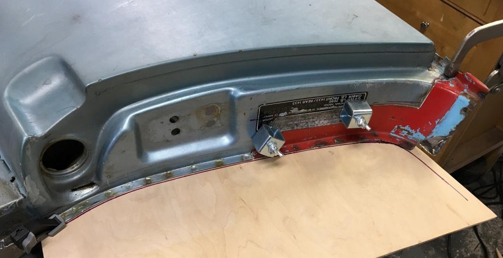
Second important view point, the lower curve.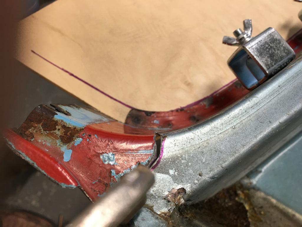
Looks like we are ready to go! And the result... 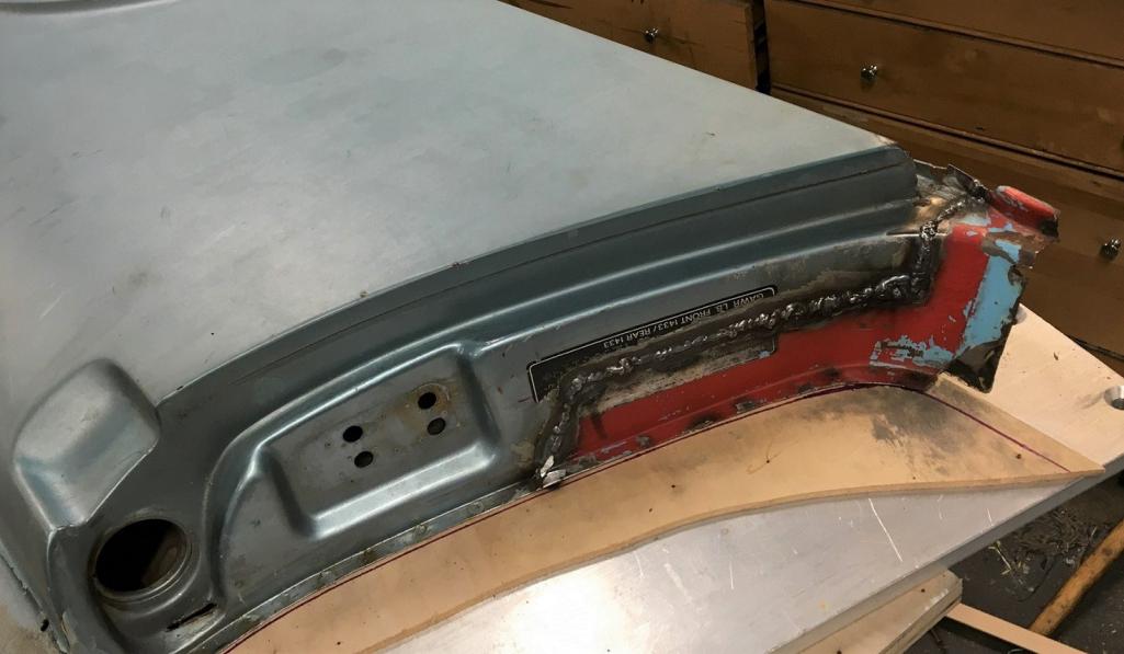
As they say, that'll buff out . Well after grinding, I ended up with this. The jamb area did not give as good a result than the trunk seal fix, but overall I am happy. A few more areas to be looked at and it will be time to remove the car's original fender in preparation for the spot welding of this one! 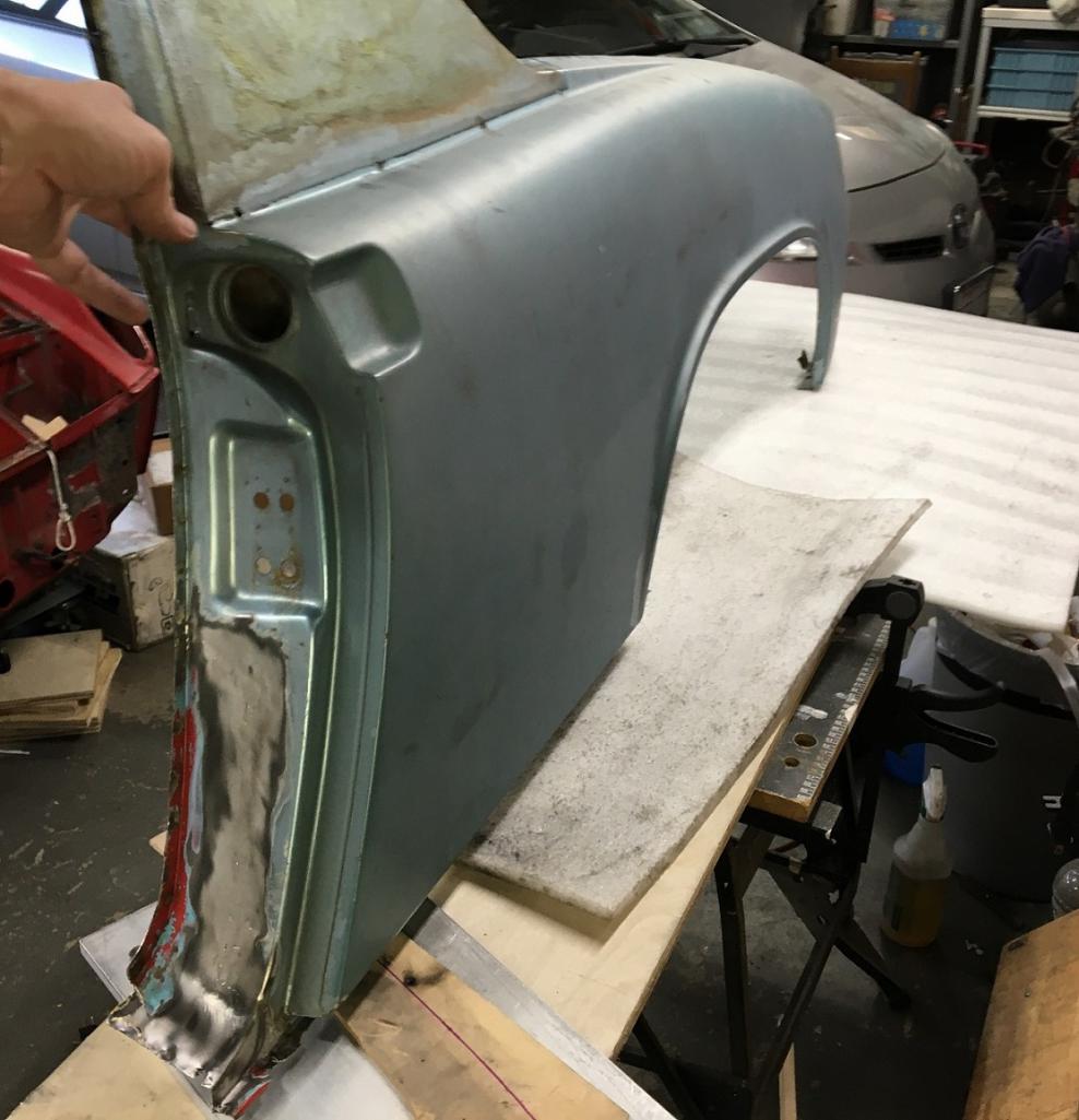
Posted by: nathanxnathan Dec 18 2022, 02:39 AM
Coming along nicely.
I'll have to take another look at the back of the trunk seal area to see how that ties in with the rear panel above the tail light.
Other areas to think about... the bottom of the door jamb, how to tie that to the sill. The factory I think gas welded that joint with bronze, as there's an overlap of the 2 panels.
The top of the sail panel where the flange goes I think under the top of the targa bar. Plug welding that seems like the best option. It's a tricky area because you can't back the weld.
The other area to think about is the fresh air inlet. The ones I've seen, the factory mig welded the lip of the 2 layers. I've removed one, and was able to just grind off the lip/weld and carefully separate the tube inner from the flanged hole in the inner fender.
What are your thoughts on prepping the inner fender before mounting it? Areas like behind the sail panels or the area where the foam is at the rear of the fender by the tail lights aren't going to be accessible once the fender is in. The factory I think there's just primer there.
I've thought about this for my front cross panel project on my car. My thoughts are 3M Weld Thru Primer on both surfaces of the seams where it'll be spot or plug welded. ... tape off the flanges that will be welded, epoxy primer, then tape off and spray weld thru primer on just the flanges — seems like the best way. I'm not sure what others do?
Posted by: Montreal914 Dec 18 2022, 02:41 PM
@http://www.914world.com/bbs2/index.php?showuser=21899 Thank you!
My comments in italic in your post
Coming along nicely.
I'll have to take another look at the back of the trunk seal area to see how that ties in with the rear panel above the tail light. Yes, that will need further investigation. My donner fender insn't 100% complete on the rear end either and there will be some butt welds needed there. So overall the installation will be a composition of spot and butt welds.
Other areas to think about... the bottom of the door jamb, how to tie that to the sill. The factory I think gas welded that joint with bronze, as there's an overlap of the 2 panels. I was thinking just weld and grind. This gets hidden by the aluminum door sill.
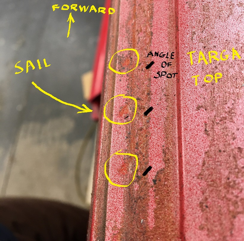
The top of the sail panel where the flange goes I think under the top of the targa bar. Plug welding that seems like the best option. It's a tricky area because you can't back the weld. Yes, plug welding seems to be the only option as the fender flange does go under the Targa bar panel. I made sure I didn't drill through the donner fender when I prepped that area. On the car those spot welds are more of an elongated shape instead of round and they are at an angle (Pictures below). Not sure yet how I will proceed to remove that part. I might try to grind from underneath to leave the Targa piece exempt from holes. Then, planned holes could be done for the plug welds.
The other area to think about is the fresh air inlet. The ones I've seen, the factory mig welded the lip of the 2 layers. I've removed one, and was able to just grind off the lip/weld and carefully separate the tube inner from the flanged hole in the inner fender. The donner fender came with all of this and I had to proceed in grinding the factory weld to clean it up. I plan on doing the same on the car when removing its fender. I didn't do the cleanest job
(pictures below) but it is done. Once the "new" fender is in, I will put a few tacks.What are your thoughts on prepping the inner fender before mounting it? Areas like behind the sail panels or the area where the foam is at the rear of the fender by the tail lights aren't going to be accessible once the fender is in. The factory I think there's just primer there.
I've thought about this for my front cross panel project on my car. My thoughts are 3M Weld Thru Primer on both surfaces of the seams where it'll be spot or plug welded. ... tape off the flanges that will be welded, epoxy primer, then tape off and spray weld thru primer on just the flanges — seems like the best way. I'm not sure what others do? AHHH YES! That is a great question that I have been asking myself...
How to prep the inner fender. If I was to apply epoxy paint, it would have to be with a brush or roller. I don't have a compressor/gun and any experience in painting. For under the car, I have been considering using those truck bed liner product and roll it on. Could this be used for both the inner fender and the fender back side? I have seen that some can be colored to match(!) the car color. A lot of questions to be answered on everything prep and paint related... Here is the sail panel top flange when I was cleaning up the extra metal from the donner fender.

And this is the top of the Targa corner on the car.
As for the vent tube, this is what I started with on the donner fender:
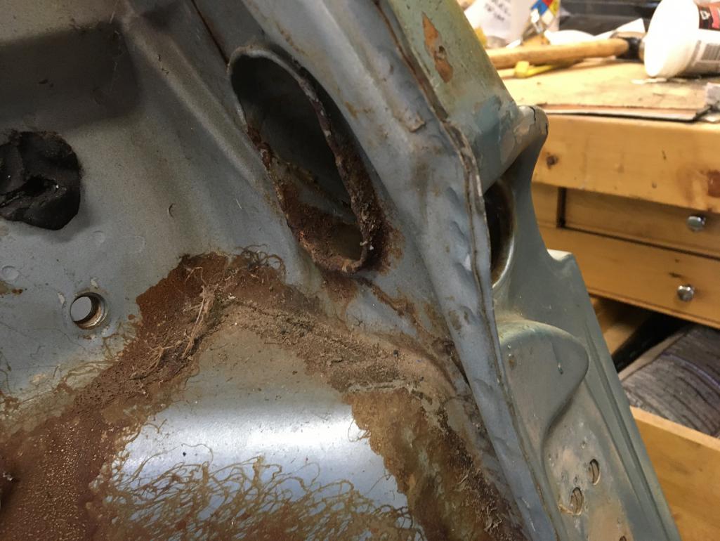
During the dismantling
A bit of a wrestle... I will try to do better when removing the fender from the car.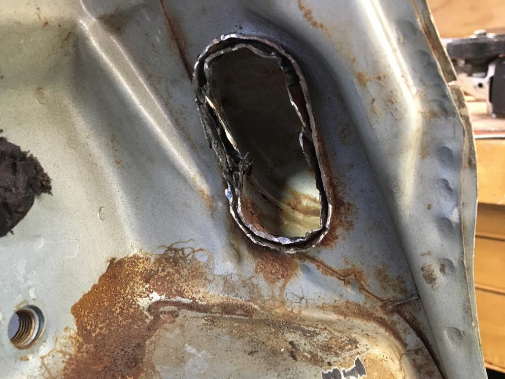
Once free and reshaped, this is what I am working with.
Posted by: nivekdodge Dec 18 2022, 08:21 PM
https://www.semproducts.com/product/rust-shieldtm/28104#product-
For the insides . it can go on over rust and can be brushed. Se if there's a local jobber who can put stuff in spray cans.
Kevin
Posted by: Montreal914 Feb 24 2023, 06:21 PM
https://www.semproducts.com/product/rust-shieldtm/28104#product-
For the insides . it can go on over rust and can be brushed. Se if there's a local jobber who can put stuff in spray cans.
Kevin
Thank you Kevin!
Will definitely look into this!
Posted by: Montreal914 Feb 24 2023, 07:04 PM
Another overdue update...
As mentioned in the previous post, the donner fender is pretty much ready (we'll get back to this...) so it was time to remove the original fender from the car.
So here is the current situation which should seem 100% familiar to everyone, except the mess... 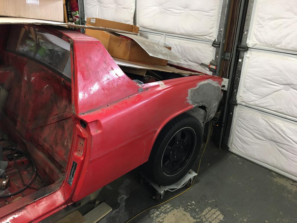
First, the vent tube in the door jamb needs to be freed. By grinding the edge weld, it allowed me to pry away the inner tube which is attached to the fender.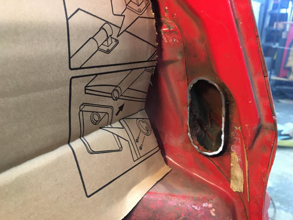
Then I cut the whole fender with a thin disk on a cheap angle grinder to leave only the spot welded strip attached to the car. This clears the access to grind the rest off in a second step. So here we go, rough cut, and out! 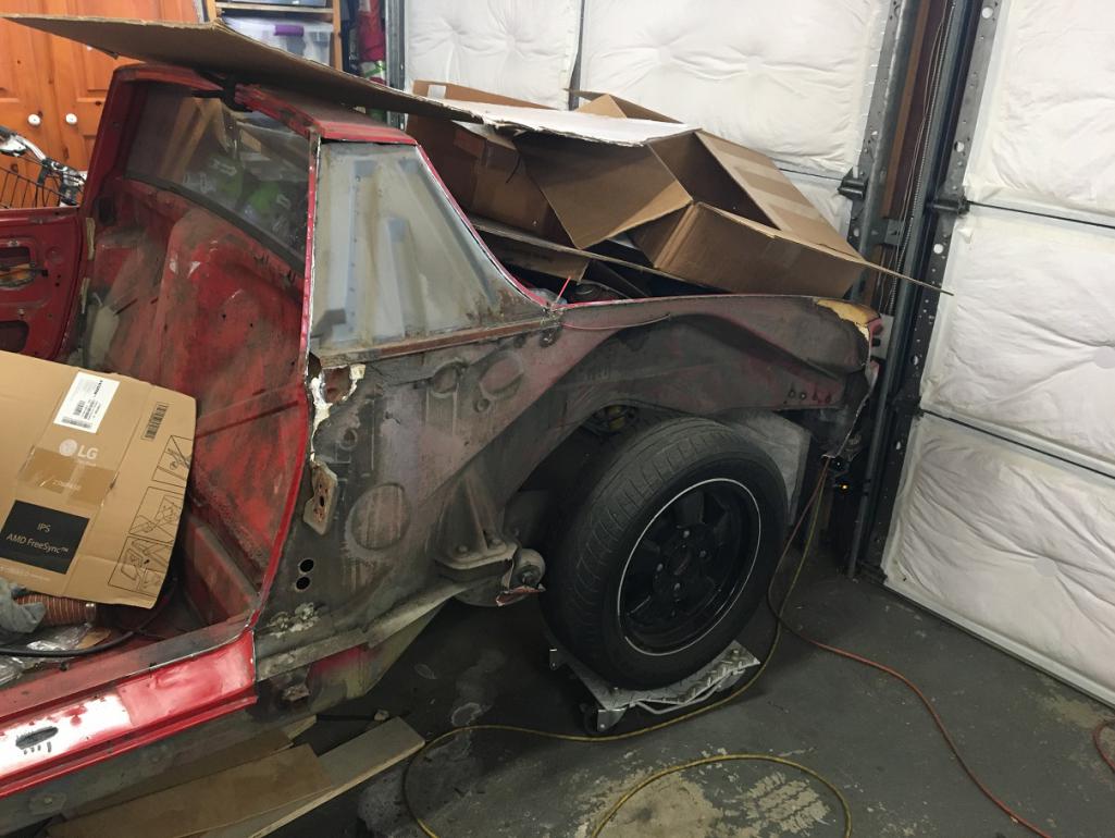
Next, I started on the top of the Targa bar. The spot welds have to be drilled here because the replacement fender will go underneath, and therefore will be plug welded in place. After drilling the welds I carefully pryed off the remnants.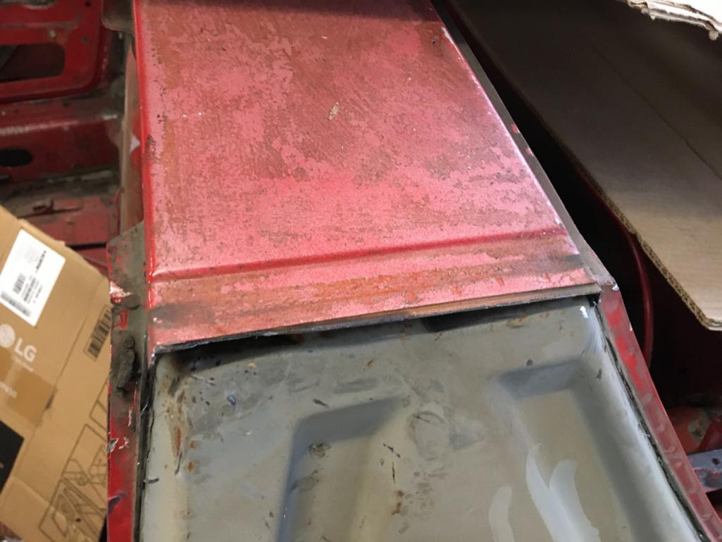
And here you have that segment pretty much done. 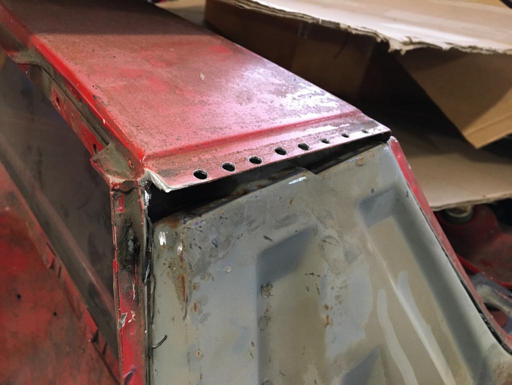
Next going down the edge on the door side. Along the Targa, there are actually three layers of metal, the inner fender/Targa panel, the corrugated reinforcement piece, and the fender. This transitions to only layers the inner fender and fender itself from the door down until the very bottom where there is again three layers. Carefully grinding away each spot weld, I was able to cleanup this flange to receive the donner fender flange.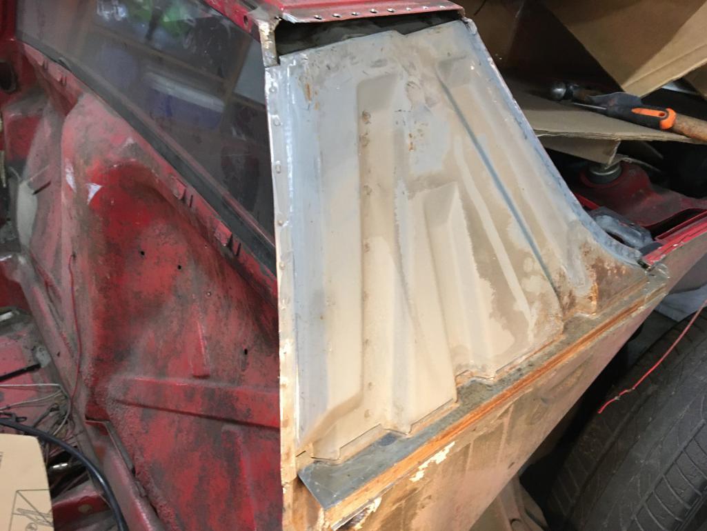
Cleanup almost finished. Note that the latch bracket is actually not attached to the fender. The fender gets sandwiched between it and the door latch.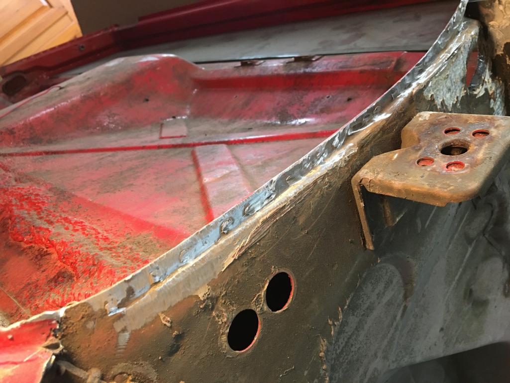
Now working my way along the trunk seal area, removing about 1 1/4" at time grinding each spot weld.
And there we have it! Well the rear corner will be addressed when the fender grafting strategy has been established... 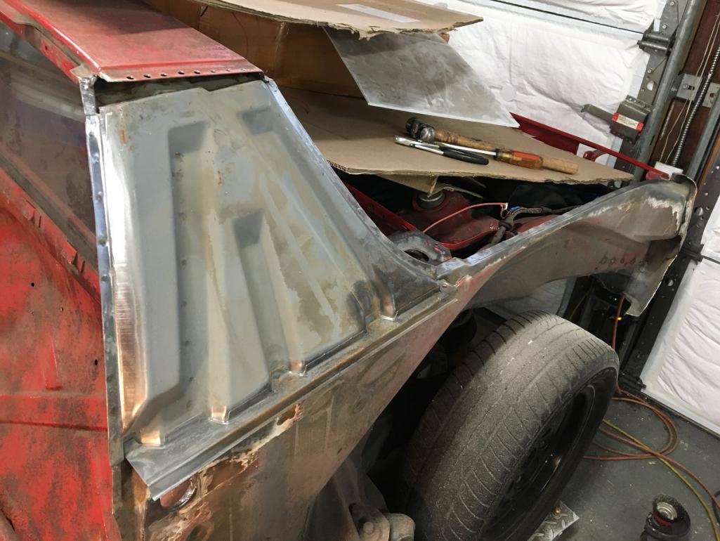
Posted by: Montreal914 Feb 24 2023, 07:37 PM
Next, time to fix some of the scars created during the rough fender cut.
The cutting disk actually cut a little in the trailing edge of the sail panel. Nothing that a little welding can't fix .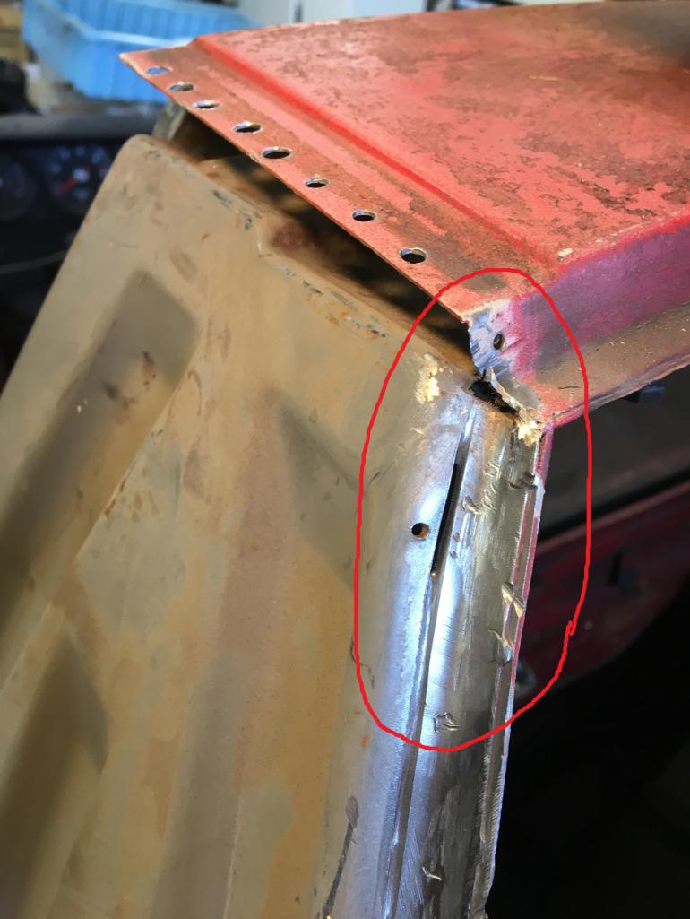
Moving along to the rear corner. Current situation, and donner fender current end cuts... 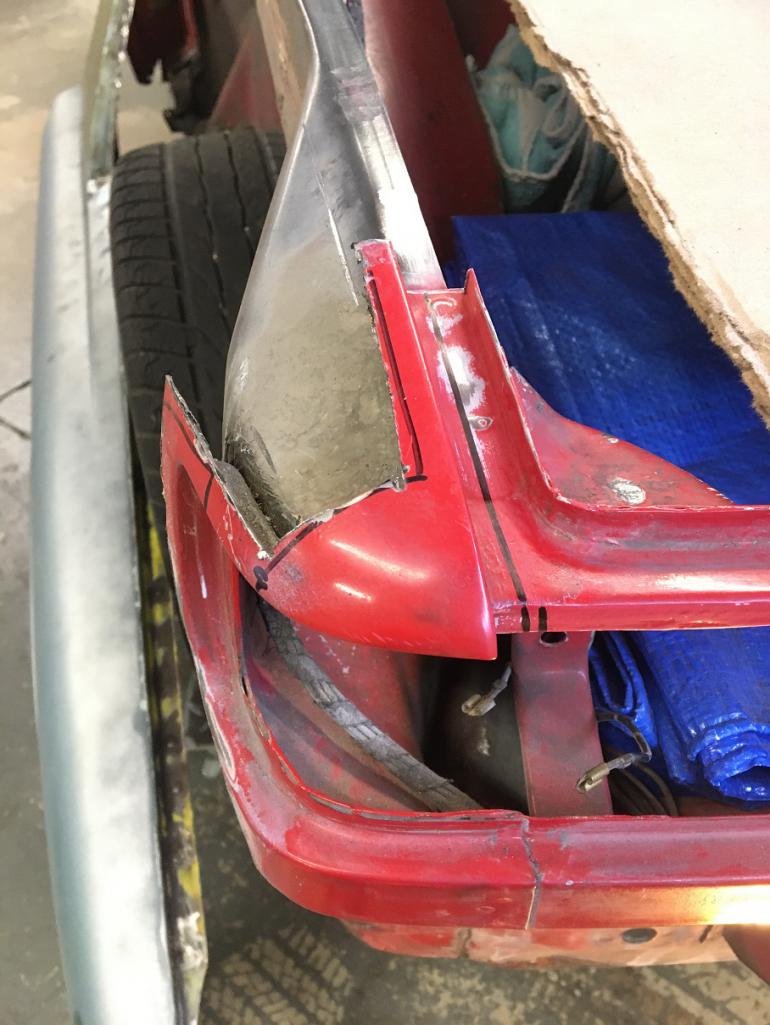
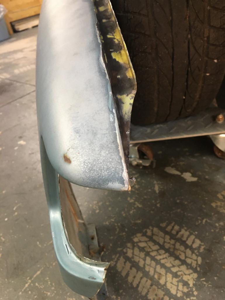
But what is hidden in the donner fender corner is the underside corner cut. 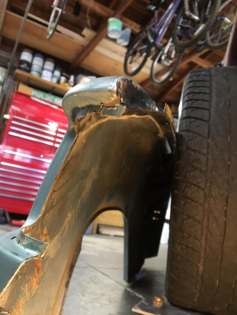
So before going any further, this needs to be addressed somehow...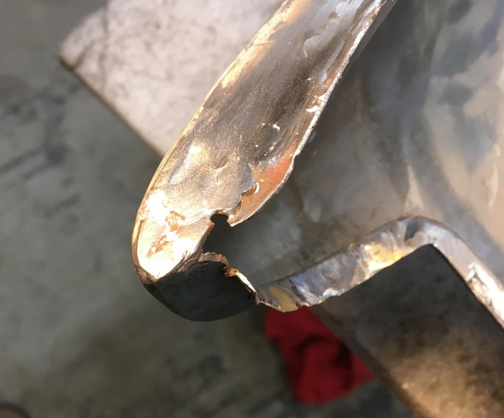
So I delicately cut off that missing portion from the removed original fender, now the "easy" task of welding this on the fender... 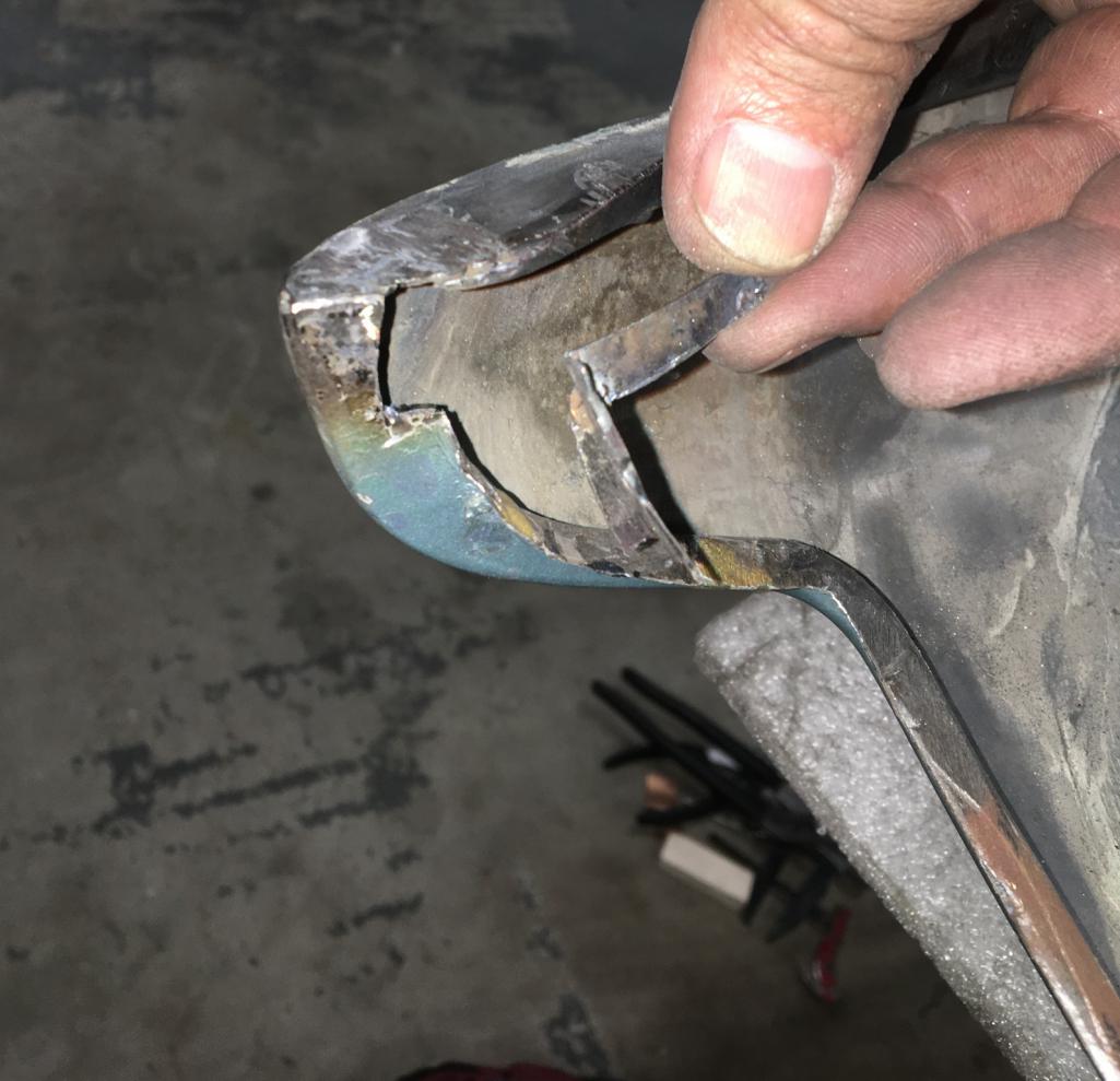
Crazy the amount of time one can spend fixing such a small area... But it got done in the end...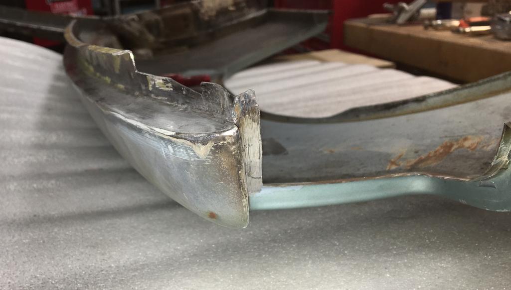
OK, now back to fitting the fender on the car. Very first placement is definitely very encouraging! 
That being said the rear end still needs to be figured out. Now all of this wouldn't have been an issue if the donner fender was 100% complete, but it isn't, so we need to improvise a little. That corner (yellow arrow) has been deformed and isn't part of the fender...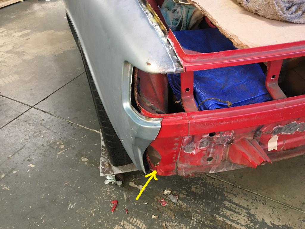
...out of space for more pictures, to be continued! 
Posted by: Montreal914 Feb 24 2023, 08:03 PM
OK, so let's continue with this problematic lower dented corner. After trying to hammer it back to match the shape of the fender, I realiazed I had cut to much material off of it and was left with too large of a gap.
So, luckily among my various sheet metal parts, I had one from the yellow fender piece. So here it is now attached to the car and nicely matching the new fender.
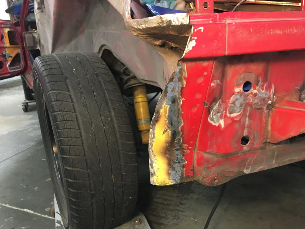
And now with the fender nicely matching ready for the butt weld. 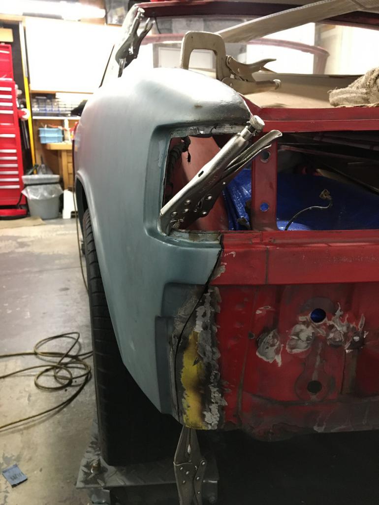
After many subtle little adjustments and on and off, I want to think the fit is pretty much ready for welding!
The door gap is pretty uniform at 5.27mm near the top and 5.08 at the bottom held by a few vise grips. Let's hope it stays during welding...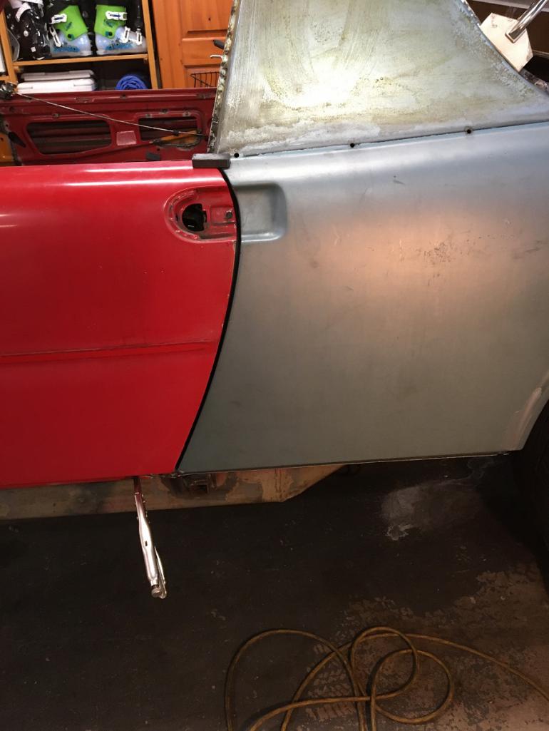
More pictures of it simply held by a few clamps.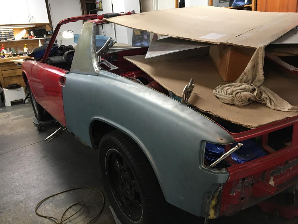
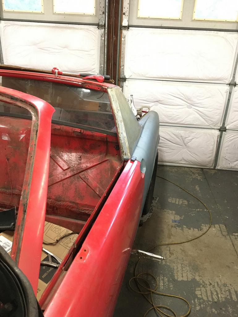
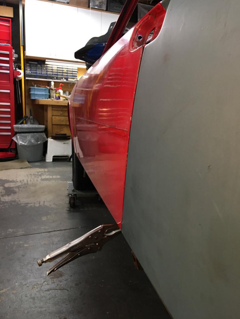
Next, prepping the surfaces and weld!
Posted by: bob164 Feb 24 2023, 08:05 PM
Great progress Eric, thanks for the detailed photos, you are an inspiration.
Posted by: Cairo94507 Feb 25 2023, 08:57 AM
Great work Eric; a thing of beauty when the new quarter goes on and lines up nicely. All that careful removal and prep pays off in perfection.
Posted by: rick 918-S Mar 10 2023, 05:31 AM
Got your text. I think I read at one time Chris Foley has a fixture for locating the suspension console if you end up having to remove it. Short of that I would spend the time and build something you could use to locate it before going too far. The car is progressing nicely.
Posted by: 930cabman Mar 10 2023, 10:57 AM
Great looking workmanship, keep it going.
the things we do for our 50 y/o machines!!
Posted by: Superhawk996 Mar 10 2023, 11:36 AM
Lots of good work going on here.
Posted by: bkrantz Mar 10 2023, 08:21 PM
Your panel fit and alignment looks at least as good as factory.
Posted by: Montreal914 Mar 11 2023, 11:06 AM
All, thank you for the compliment!
All of your build threads have been inspirational and an extremely valuable source of information.
I will be moving on a new dreaded phase of the project, the longs... Hopefully, the level of repair needed will not be as extreme as what you guys had to deal with.
I bought the car 13 years ago when I moved to California from Canada and this was my only means of transportation for many years! A few months after purchasing it and joining the forum, I discovered heavy rust in the jack point area. I did a temporary fix over a couple of weekends with a Brad Mayer repair kit that allowed me to drive and enjoy my car for many years. I think this was the right decision.
Now the time has come to remove the Brad Mayer parts, investigate and properly address the rusted areas.
I am hoping I can achieve the passenger side without removing the rear fender, and using methods shared by Rick and Superhawk. Fingers crossed.
Stay tuned, more to come!
Posted by: Montreal914 Apr 8 2023, 06:40 PM
Before I continue I need to take a few step back and investigate a repair the DACO (Dumb Ass Current Owner) did about 13 years ago... 
At the time, I had just moved to California from Canada and the 914 was my only mode or transportation (excluding my bicycle)! Therefore I needed a quick fix for both driver and passenger side jack point pyramids that were rusted and had impacted the longs. I bought a used 120V welder on Craigslist and proceeded to make this repair in my driveway (no garage on the rental). I had access to a few very basic tools too.
Anyhow, the Brad Mayer repair panels did the trick and allowed me to enjoy my 914 for about 10 years before I started this now rebuild project.
For the past while I debated weather I should go back and revisit this repair or simply continue as is.
That was until I decided to remove the back portion of the Brad Mayer panel on the right side and discovered this!
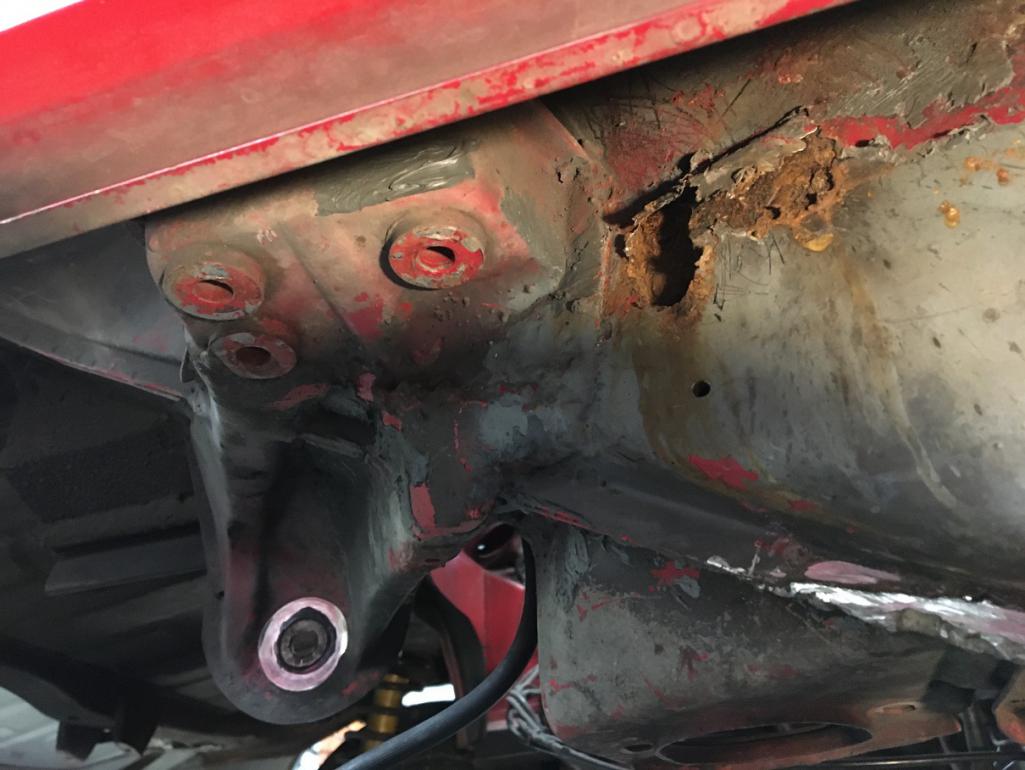
So clearly this will require a thorough investigation that will get pretty deep.
So, although the repair panels were a success as they did what was needed, it is time to go through all of this and fix it the right way.
Step #1, getting the proper dolly for the car. I have no clue how far this will go, and I need something to move this shell around anyway so... After reading many of the rebuild threads here, I decided to make myself a similar copy of the Jigster engineered by @http://www.914world.com/bbs2/index.php?showuser=7712
With today's steel prices, the 4" x 2" x 1/8 20ft. that Jeff used are about $150 ea. and 2 are needed for this build.
Instead, I went the frugal way and got some used racking beams and used heavy duty casters. Total investment, a whopping $72!
Here are the beams purchased: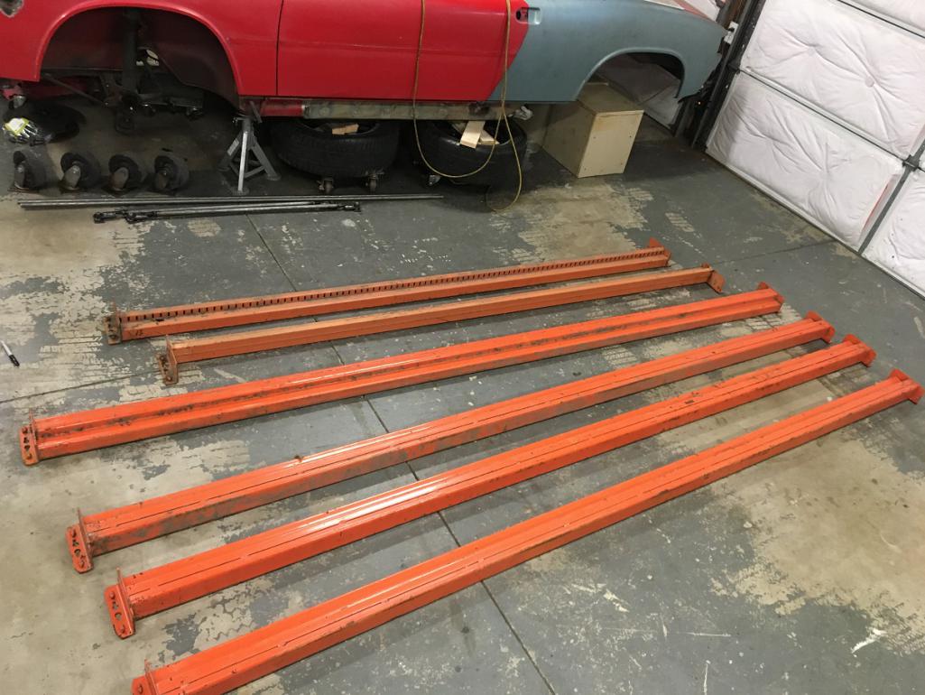
Now to cut these square requires the correct tool that I obviously don't have as I am not a metal fabrication shop...
This is where reading can give you tricks! I got myself a 10" thin abrasive disk with a 5/8" arbor and set it on my wood miter saw. Make sure your disk is rated for the speed of your saw!
Time to do some cutting!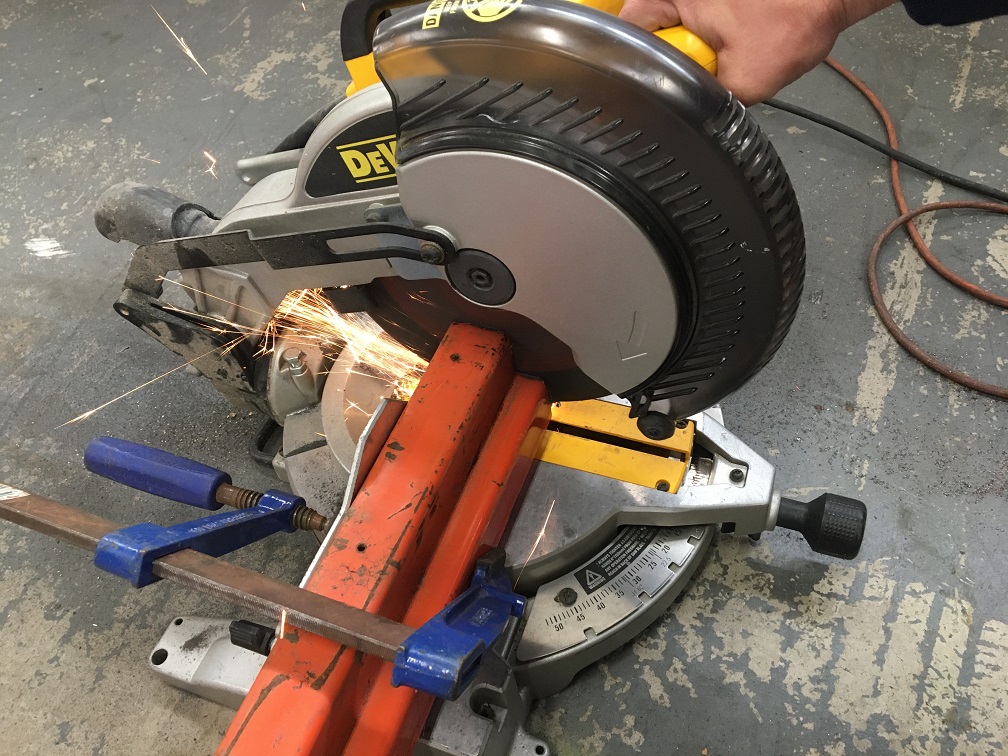
And here are all the parts cut to length within less that a 1/16" off. 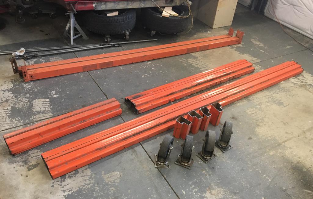
Time to burn metal Using a laser I set the beams leveled and tacked the 4 parts of the frame. After measuring the diagonals, I was within less than 1/16" and nicely leveled. Time to fully weld this thing!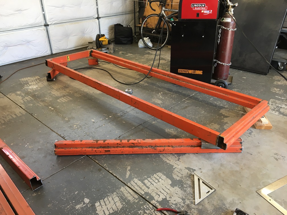
Flipped upside down to do the legs and casters.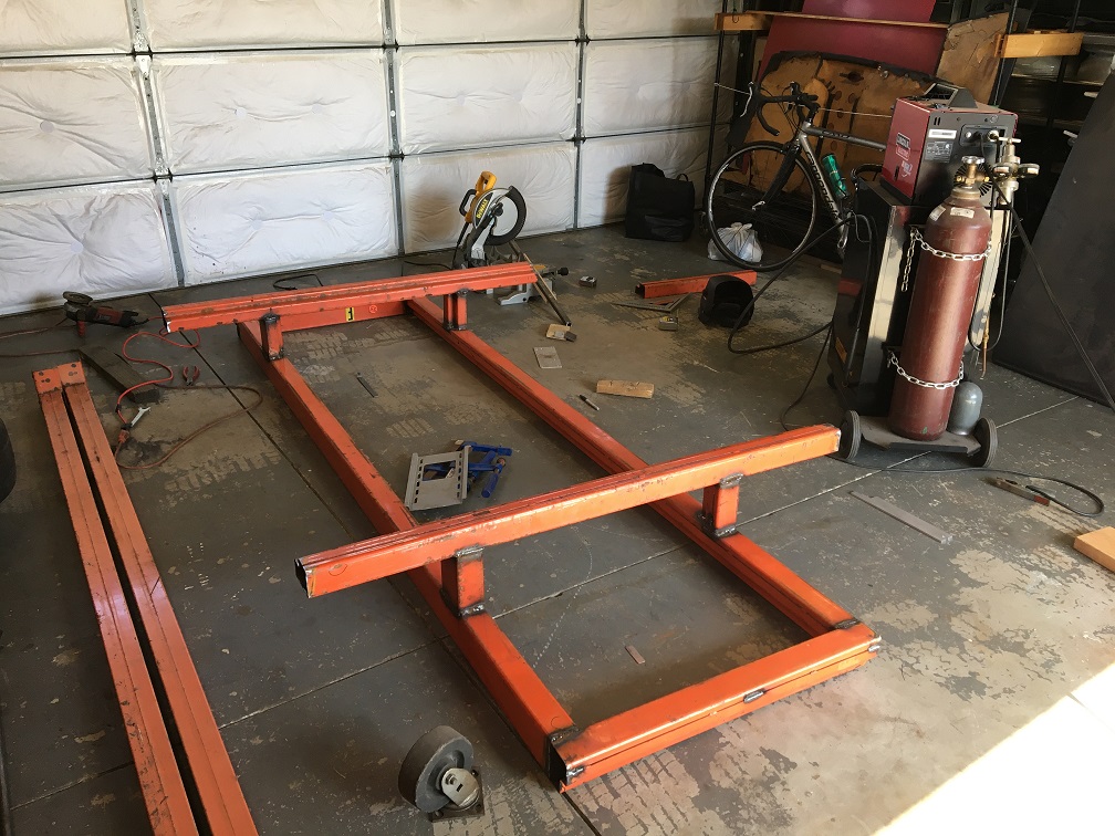
For the casters I got lucky as a piece of 1" x 1" tube I had made the perfect spacer for the caster plate. The correct way would have been to have a plate and bolt the casters, but I went the easy way and just welded them on. I doubt I will ever have to replace them anyway...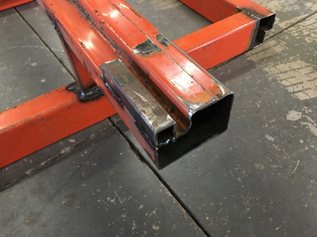
Once done I sprayed some left over rattle can paint over the welds after wire brushing the areas.
I am very pleased with the result and can now plan on setting the shell on it and begin the long repair how ever deep I need to go. I know I will be able to make which ever brace will be needed for key reference points such as suspension console. It was a long day but well worth it! 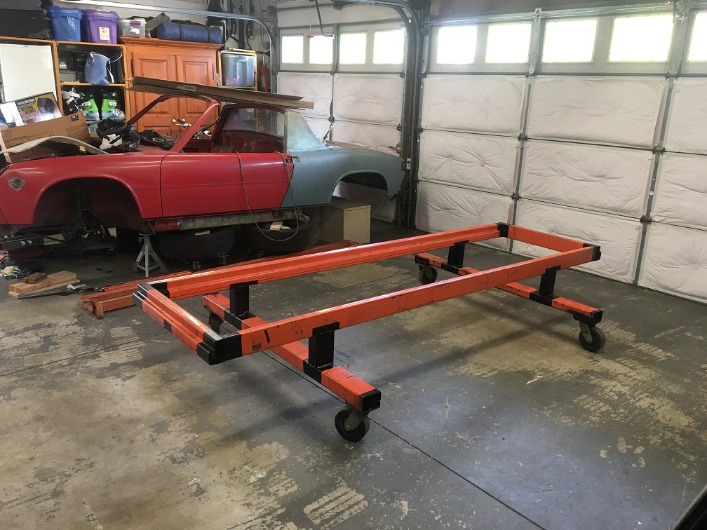
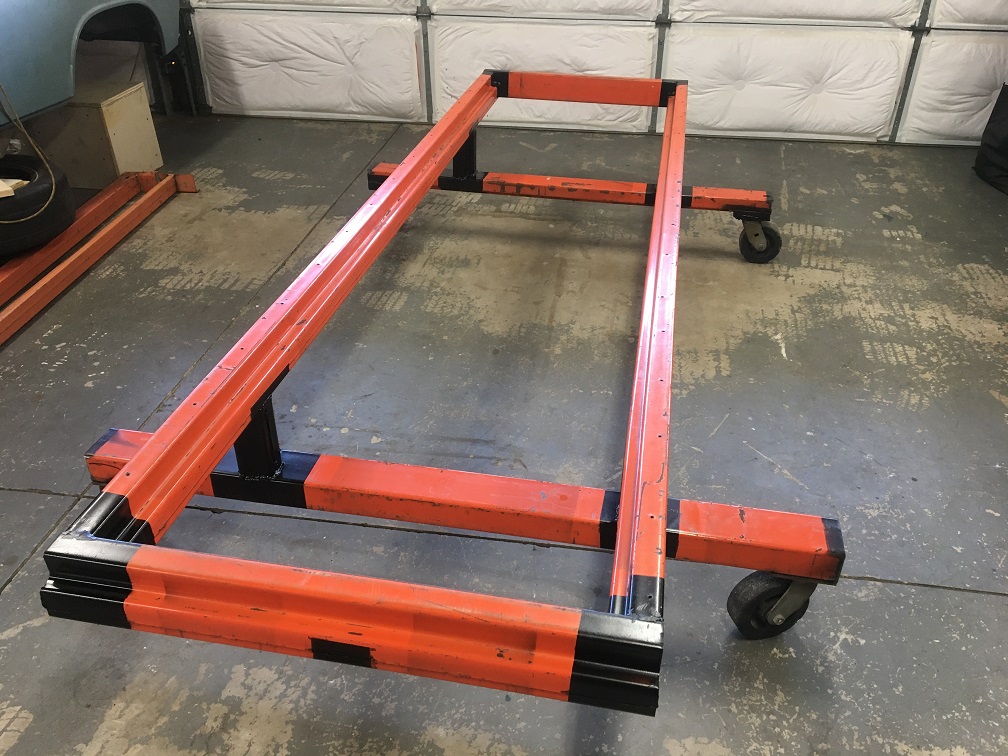
Posted by: rick 918-S Apr 8 2023, 08:32 PM
That should work nicely
Posted by: nivekdodge Apr 8 2023, 10:19 PM
OK, so let's continue with this problematic lower dented corner. After trying to hammer it back to match the shape of the fender, I realiazed I had cut to much material off of it and was left with too large of a gap.
So, luckily among my various sheet metal parts, I had one from the yellow fender piece. So here it is now attached to the car and nicely matching the new fender.
And now with the fender nicely matching ready for the butt weld.
After many subtle little adjustments and on and off, I want to think the fit is pretty much ready for welding!
The door gap is pretty uniform at 5.27mm near the top and 5.08 at the bottom held by a few vise grips. Let's hope it stays during welding...
More pictures of it simply held by a few clamps.
Next, prepping the surfaces and weld!
Nail That Eric , looks excellent
Posted by: ChrisFoley Apr 9 2023, 03:52 AM
I like that!
Posted by: Montreal914 Apr 21 2023, 07:13 PM
Time to put the tub on the Jigster (Jeff Hail's TM ).
Working alone as usual, so one step at a time. Need to bring the car 25" up (from long lower edge). Using a small 2 ton jack and all sorts of methods... , I slowly raised the car in steps constantly checking how stable it was... 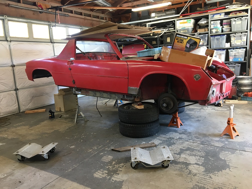
Once there, I wheeled the dolly delicately going around the jack stands. 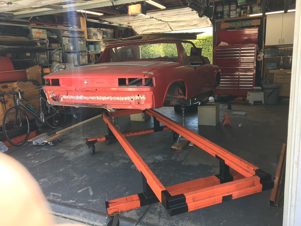
Sometimes you get lucky... The caster went by the rear driver side jack with about 1/16" clearance. 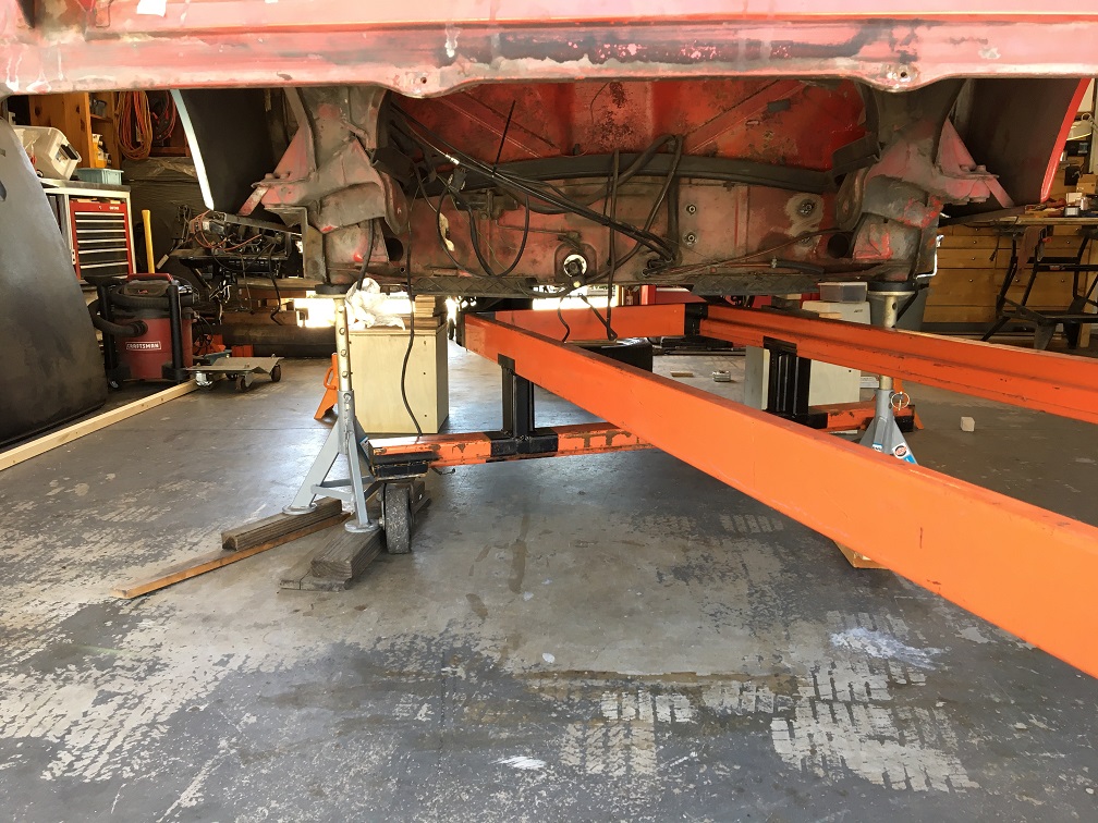
Almost there, just need a little more height in the front. 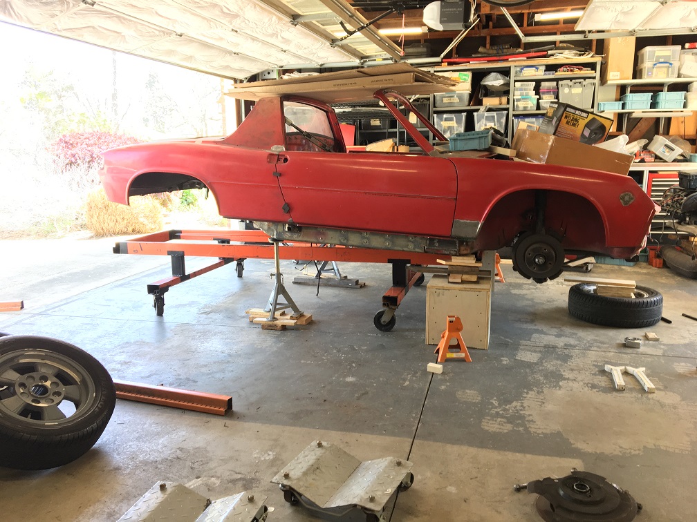
And finally, the tub is now resting on the Jigster and can almost too easily get moved around.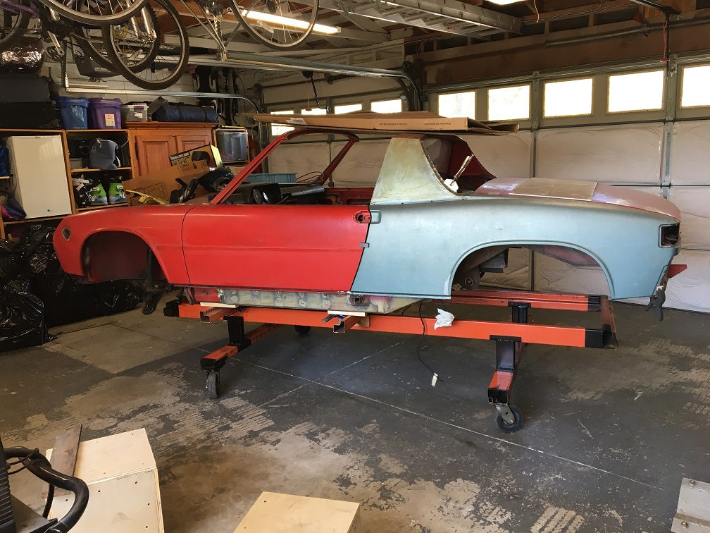
And at the end of the work day, it can be tucked in its corner, leaving the garage for the daily car. 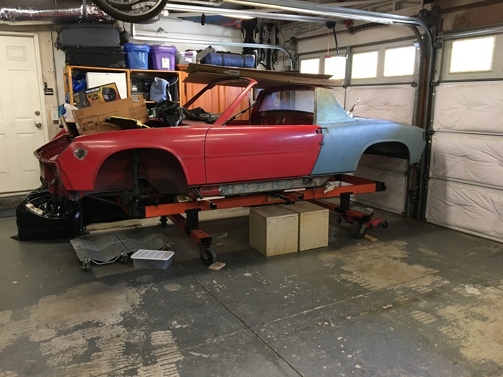
Posted by: Montreal914 Apr 21 2023, 07:23 PM
So, as mentioned earlier, the car is currently set with Brad Mayer repair panels. I installed those 13 years ago to enjoy my car daily.
This was a nice patch and it definitely served its purpose, but it is now time to revisit the area and properly fix the problem.
I made some braces with 1" square tube and large turnbuckles to minimize the car's movement. I plan on anchoring the tub accordingly on the dolly, but the first part is to assess the situation.
I will begin with the driver side as I am hoping it is in better shape than the passenger's. This way I can somewhat get used to the longitudinal repair work.
Step one, removing the door sill so I can have access to the weld that are on the top.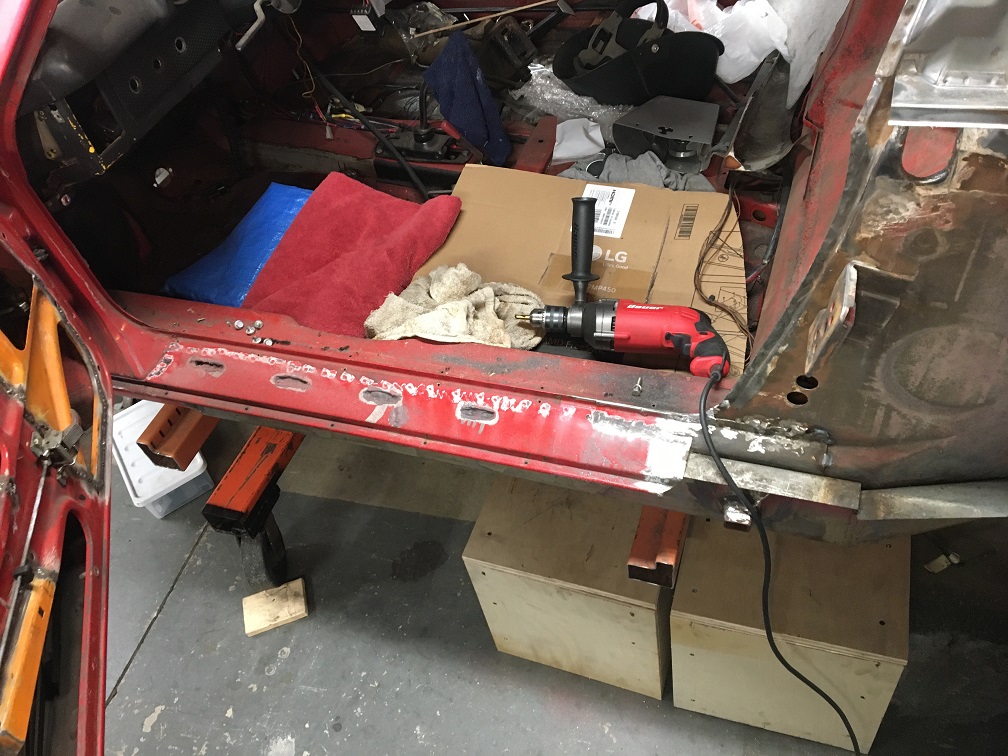
I used a 3/4" hole saw and cut around the 10 plug welds on the vertical part of the panel.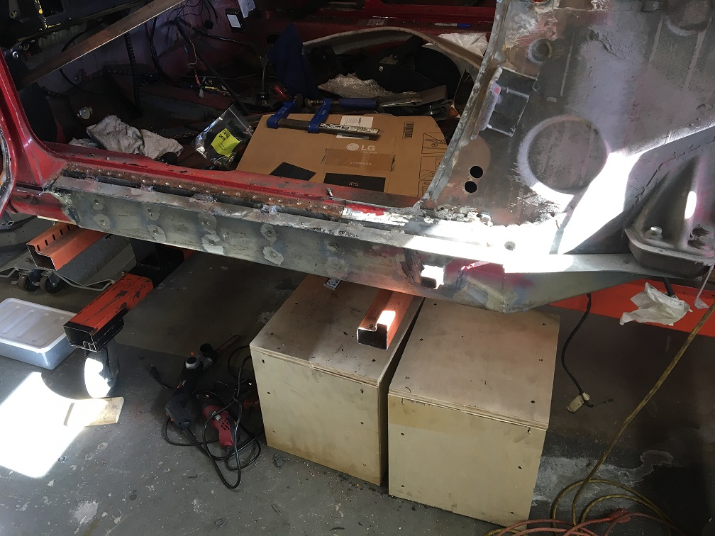
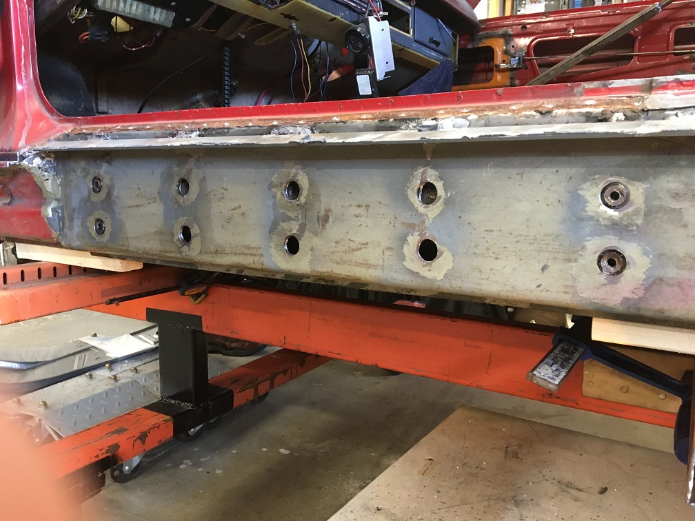
Then the pain of grinding all the various welds around the panel without damaging the original sheet metal... ...Finally, it is off! 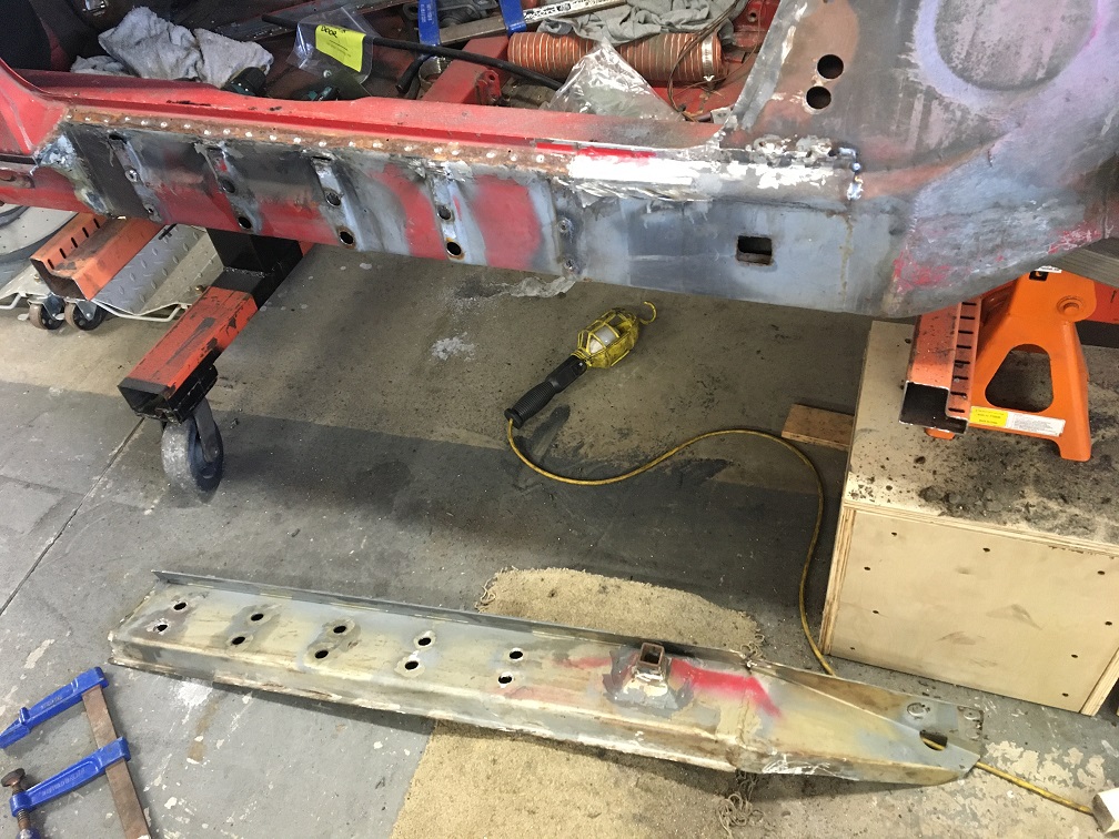
Now, the good eye will notice the jack point area to be somewhat different.
At the time, to reinforce that rusted area, I made a patch with the very limited means I had...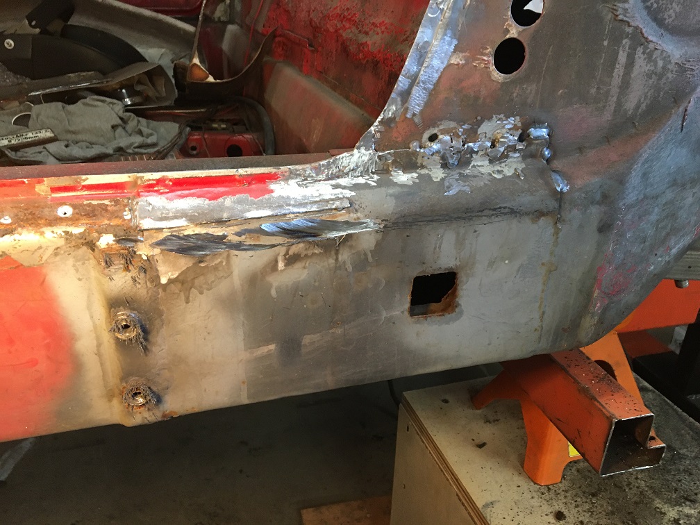
Well, 13 years later, nothing improved behind it... ...but nothing isn't really worse either...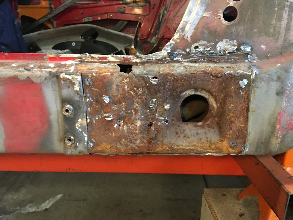
Clearly, I will be in need of new metal there, that being said, there are no reproduction of this piece...
I cut out a window allowing me to take some pictures inside.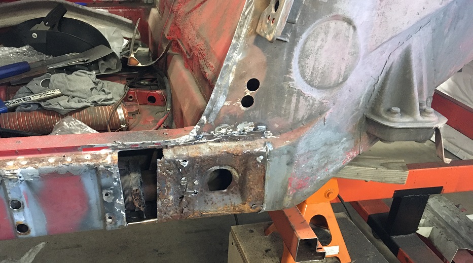
Looking towards the front, things don't look too bad. We can see the indent for the emergency brake lever (arrow).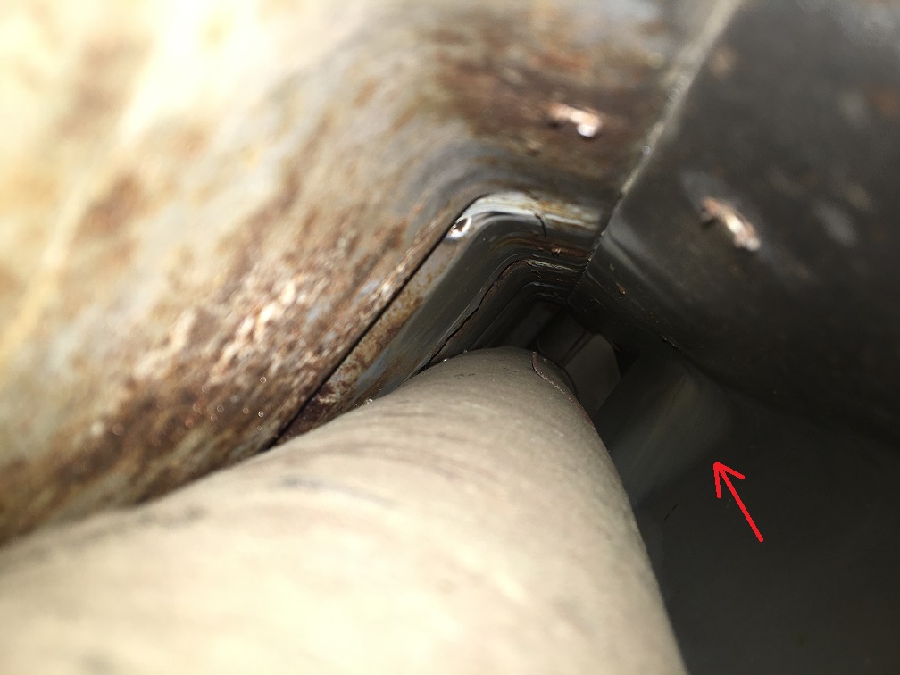
Now looking towards the rear, I am concerned by the circled area. The rust on the panels seems to be more than just surface... 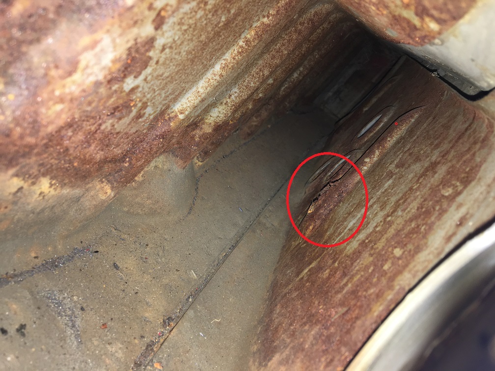
So I decided to cut out a little window on the outside surface and discovered this... 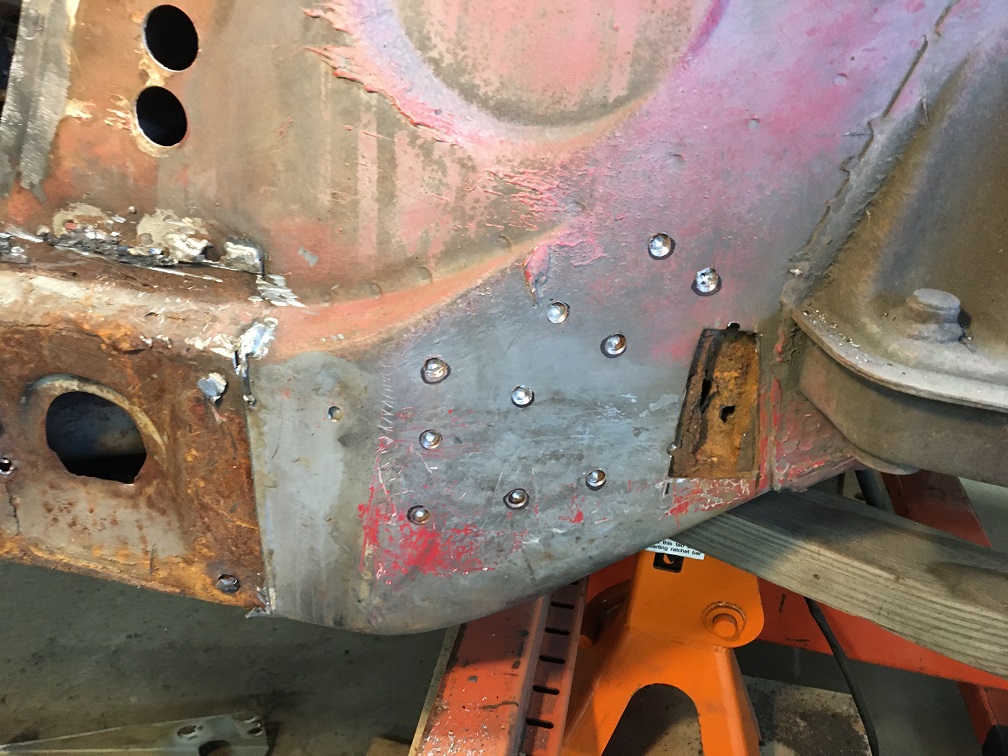
So, I made a larger window...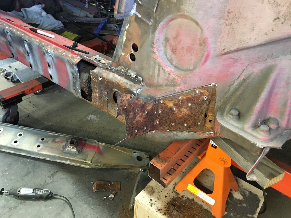
This is definitely more than surface rust which means this whole section will need to be replace, inner and outer layer...
Now, when looking at he picture again, the inner side of the long doesn't really seem to be in better shape rust wise. I fear the rust between the corrugated inside inner and the inside outer layer will be the same as what we see in the last picture. This would mean rebuilding the whole long including dealing with the removal of the suspension consoles, and engine mount... And this is the driver side... clearly the passenger will probably not be better...
Not sure how to proceed here... Looking at the suspension console area and the rest of the engine compartment, it would be difficult to even think the level of rust that is inside. This tells me that probably most of the 914s even in decent conditions have a generous amount of rust in those layered area.
Posted by: 930cabman Apr 22 2023, 06:43 AM
The lengths we go to save our 1/2 century entry level sporting machines. Very thorough and keep the energy moving ahead.
Posted by: Montreal914 Apr 22 2023, 10:15 AM
Yeah... Spent the night thinking about a strategy to tackle this... I have to say, I did really consider abandoning here and find myself another 914, but I fear a lot of them have this in-between layer rust issues. Anyhow, I am in too deep to stop, and I know I can find the right support here so I will fix this.
Does anyone know if both inner and outer suspension consoles and engine mounts are spot welded to the outer layers of the long or through the outer and inner layers (which would make more sense strength wise)? @http://www.914world.com/bbs2/index.php?showuser=21899 , @http://www.914world.com/bbs2/index.php?showuser=20845 , @http://www.914world.com/bbs2/index.php?showuser=23343 , @http://www.914world.com/bbs2/index.php?showuser=22428 , @http://www.914world.com/bbs2/index.php?showuser=43 , to name a few of my build threads resources
At this point, I will borrow @http://www.914world.com/bbs2/index.php?showuser=21899 's nice cross section and lexicon to make sure everyone can follow.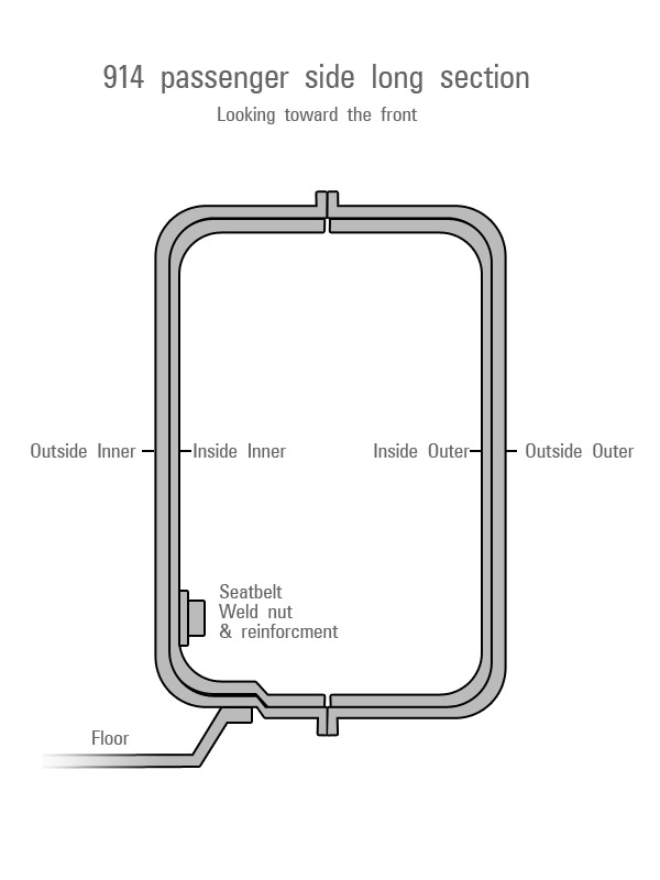
Just wondering how some of these components could be removed/installed individually or a few at a time.
The more I look at it, it seems this large portion of the inner fender (Outside Outer and Inside Outer) will come out, maybe with the outer suspension console attached (?). 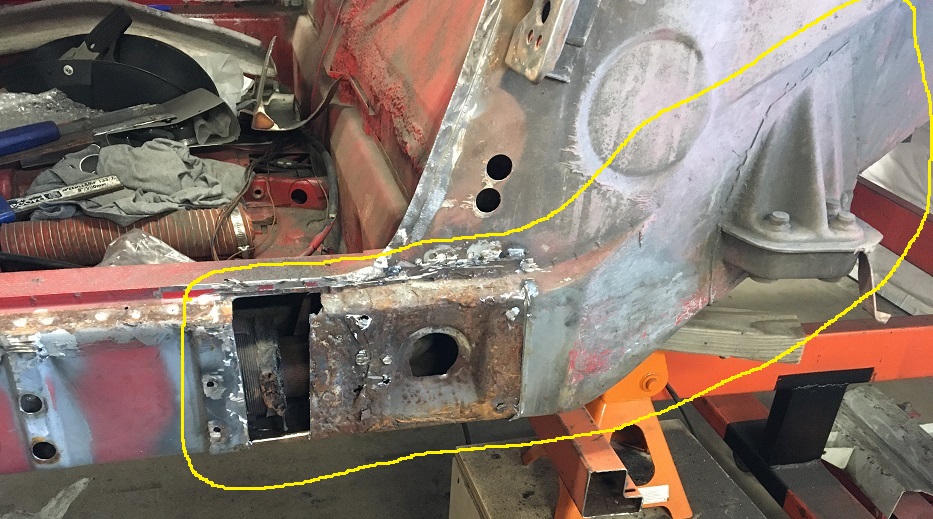
This will expose the Inside Inner corrugated part. Then making a window in the corrugated part, I could investigate the level of rust in between the Inner long two layers (Inside Inner and Outside Inner). This might save me from removing the inside suspension console and the engine mount. All of these components look very good with original paint still on BTW. Which adds to my concern of the rust going from inside out...
A couple of pictures I quickly took last night. This not a restored car, but far from being a complete rust bucket, yet, it sort of is... 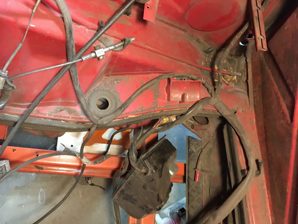
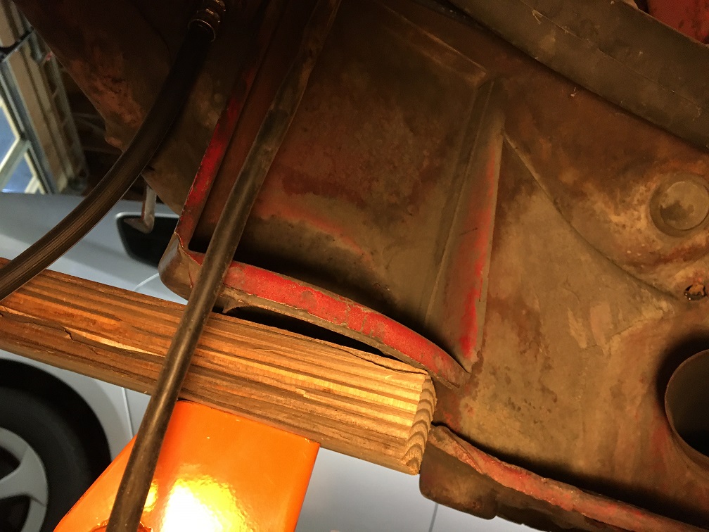
Posted by: Superhawk996 Apr 22 2023, 11:10 AM
1st let’s answer your question.
Suspension console is spot welded through 1 layer of steel on the outer long. Here is the picture of mine: 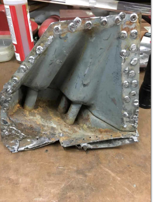
So what to do with yours? That is a really a tough call. Cutting out the entire long is feasible - that is what I did on the passenger side. Mine was simply roached completely. See the 1st couple pages of my thread in signature. The problem is in the driver side, the complete panels aren’t available from AA or RD like they are for the passenger side. So it would be a TON of fab work to make what can’t be purchased.
In your case, it doesn’t look quite that bad from the photos you’ve posted.
If you can avoid removing the whole long and just patch where necessary, I would. Sure there will be rust between the corrugated inner and the outer but unless it’s completely compromised, I wouldn’t cut it out.
Maybe cut some access windows. Spray in Ospho? Maybe other rust converting / encapsulating paint like Eastwood frame spray or any other converting paint? Treat it as completely as you can with access holes, then weld up the access holes?
Posted by: Superhawk996 Apr 22 2023, 11:18 AM
What you have is worth saving. Don’t give up. You’re doing a great job! 
You are at the phase of OMG - what have I done 
Once you wrap your mind around it and start moving forward, you will feel much better.
I applaud you for pulling the Brad Mayer panels. They serve the purpose they were meant - keeping cars on the road. But they are heavy and will be unnecessary when you make the repairs you’re doing. These cars were mean to be Lightweight - no need to be carrying around extra steel plate when you’re done!
Also take a look up in the engine compartment at the top of the longs - you will find access holes there that lead into the top of the long. This is a great access point for Ospho and rust converting paint.
Posted by: Montreal914 Apr 22 2023, 12:11 PM
Thank you Superhawk for the pointers. I am going to see Vince now (1 hour away) to see what panels he has in his yard. I know the driver's side isn't available from RD, AA. I have already gotten the inner fender well for the passenger as the rust is poking out fore of the outer suspension point. As for the hell hole, there was a repair done prior to my ownership. I plan on opening it up to see how that looks. I did locate the hole at the top of the long and may get one of those cheap borescope.
Good to know the grafted elements (suspension consoles, engine mount (hopefully)) are only attached to the outer layer. This may come handy to separate parts.
Yeah, I feel like my car is pretty solid (no signs yet of floor rust), but it is clearly affected by rust in the key structural area. The Brad Mayer will not go back on, for sure. But I will reinforce some areas. Inner kit, outer clamshell, GT kit are all options on the table, maybe partial components.
Posted by: Superhawk996 Apr 22 2023, 12:27 PM
Give my regards to Vince. He provided front bulkhead sheet metal and a tunnel for my project. Would have been hell without his donor metal!
You’re lucky to have him so close!
Posted by: rick 918-S Apr 22 2023, 12:28 PM
It is always hard to know when to stop. I mean you could really dissemble the whole car and never find all the rust. I am not upposed to drilling access holes just large enough to slide in the long tube you get with the Eastwood encapsulator and flood the spaces. Some two part epoxy injected in the holes will seal them without welding and burning off the encapsulator. Just a suggestion.
Posted by: altitude411 Apr 22 2023, 12:55 PM
Am I mistaken or is this area in blue the only place the outside long is double walled? I thought it was only double walled in the area of the overlap where the inner fender and the outer long piece butted together? (sleeved)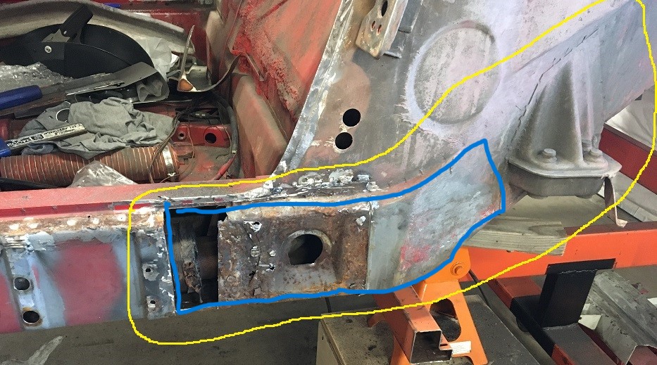
* Edit, just found these photos courtesy of Luke M Maybe of some help to you for reference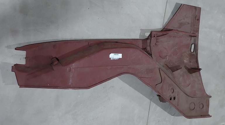
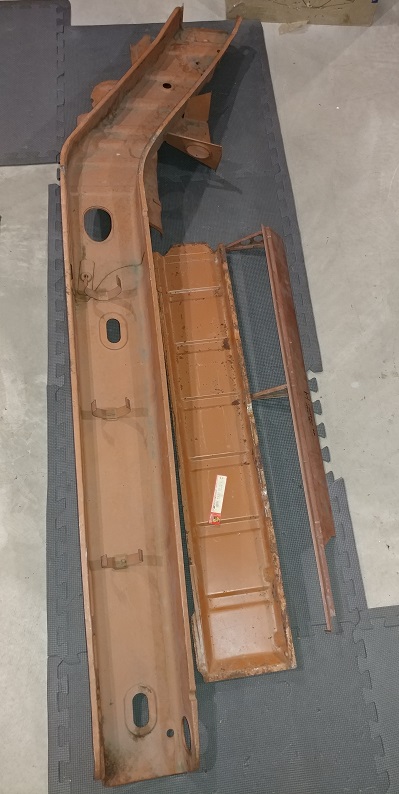
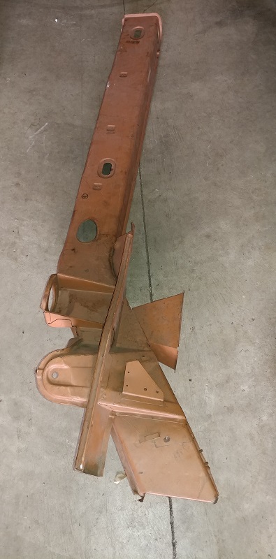
Posted by: Montreal914 Apr 22 2023, 05:38 PM
Well, it was worth the trip to Vince's. I did pass on the hello on your behalf and all of the World. He mentioned not remembering everyone as he regularly ships parts all over. And yes, it is quite a blessing to have him close by for such projects. Parts are getting a lot harder to find for him due to rarity of the abandoned cars. Also, cars that he might have cut in the past now are kept whole for potential buyers.
Altitude: Those are some very good looking sheet metal components!
That being said, I think I found some good parts for my repair. I was hoping to find a whole piece to replace the outer portion basically including the jack point all the way rear of the suspension console. Instead I got that in two parts and a whole lot more .
Here is today's lot brought home: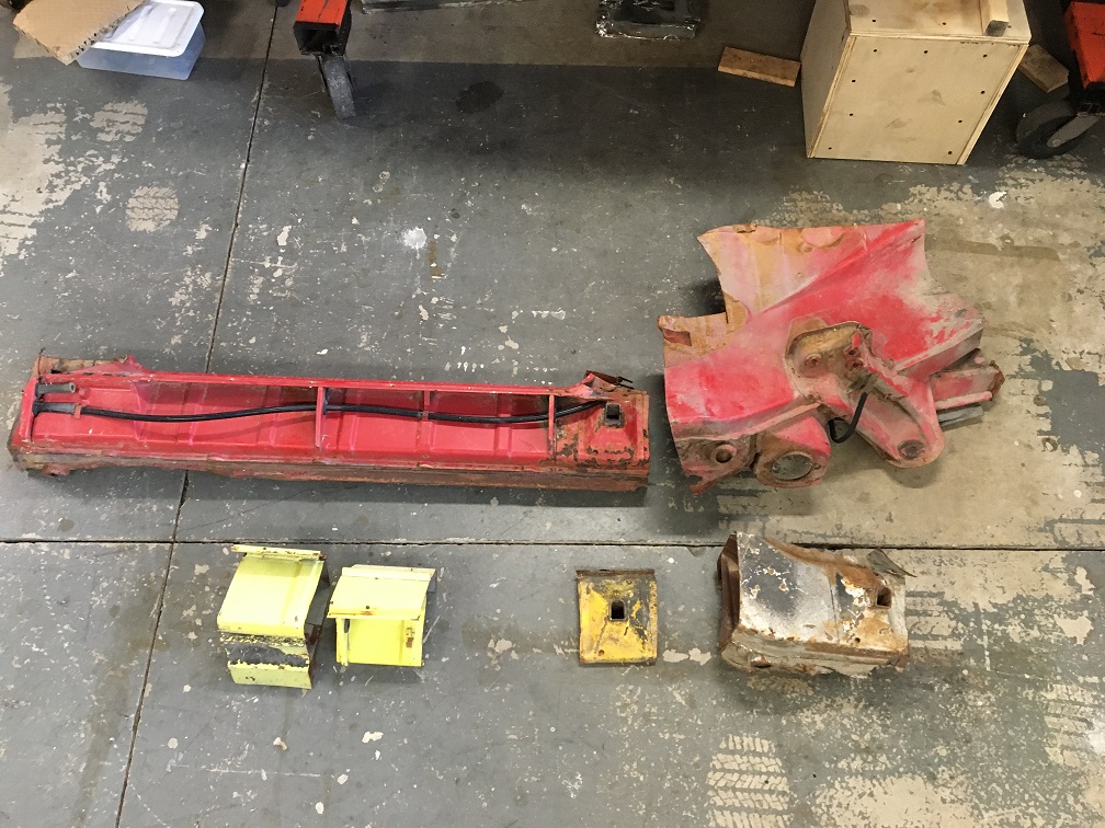
The red parts are actually from the same car but unfortunately was cut in two. The cut matches though so other than it, it is complete.
The jack point on it isn't the greatest but that is OK as I got two other ones too.
Now looking inside the rear part, it is pretty much gray, not rust. This is very encouraging! 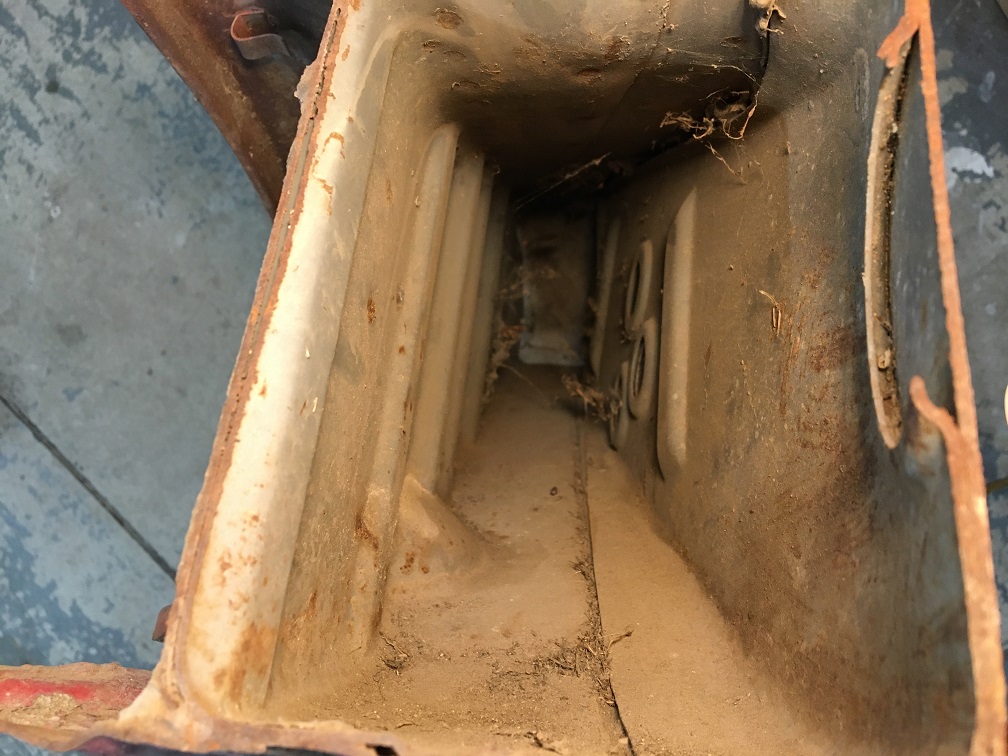
Not sure yet how I will tackle this but I might simply replace the outer with the "new" part as-is, meaning the whole outer two layers and suspension point in one transfer.
With all of the outer removed, it would give me access to the Inside Inner (corrugated). Now that it was established that the spot welds of the inner suspension console isn't through the inner (corrugated) panel, I could remove it by drilling the spot weld and investigate the rust between those layers while leaving all of the engine side as-is.
Once the corrugated removed, I could replace it with the "new" one. This would basically replace 3 of the 4 layers from outside without drilling any of the suspension consoles spot welds.
The plan is starting to take shape. One of the question is; where to cut the Outside Outer on the car? Maybe about 3/4" above the upper line of spot welds, sort of like the RD part that is available for the passenger side?
Posted by: Montreal914 May 28 2023, 09:11 PM
Another month goes by...
After a trip to Portugal where we enjoyed a lot of wine, especially Port and Pastel de Nata , time to get back to work!
Before tackling any more cutting of the frame, it was time to complete the work on the Jigster (Jeff Hail's TM ).
Using the horizontal and vertical laser, I set the Jigster leveled and made sure the car was not only leveled, but also on the center line of the Jigster. Then I did a bunch of Z axis measurement to see how things were. I was happily surprised to see that everything was within about 1/32"! . This was encouraging despite all of the recent rust findings. I also measure the lower edge of the car's back panel and it was the same on both sides. This has been a concern since seeing the car had been hit in the back.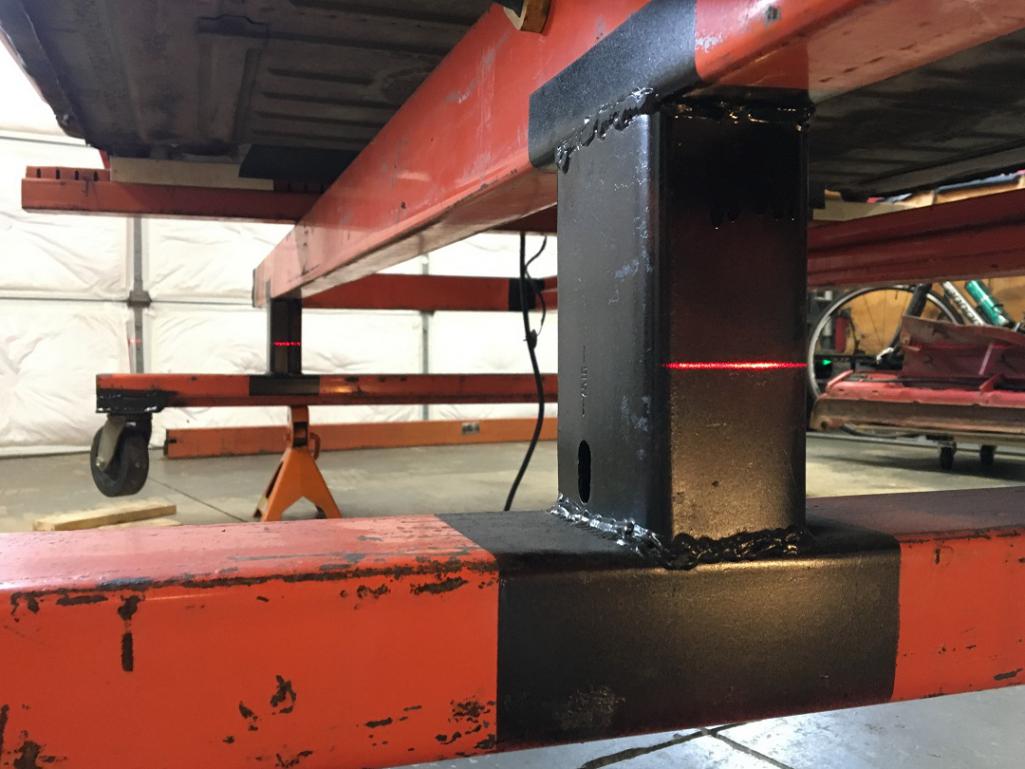

Up to this point the car had been resting on wooden 2"x2" under the longs. If I am to start cutting the structure, I need to make sure things are held. Time to bolt the car to the Jigster!
With the car and Jigster now perfectly leveled and centered, I fabricated brackets, then bolted them to the car's front suspension cross member rear mounting point and welded them to a cross beam. 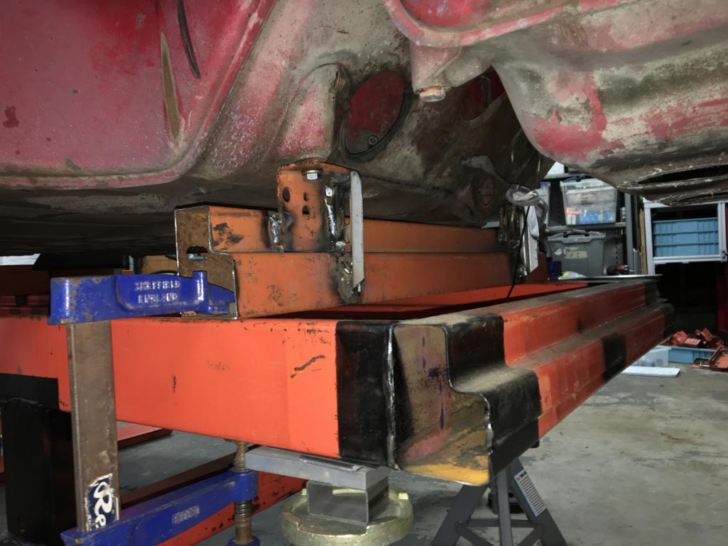
Then similarly in the back, I made brackets and mounted them to the engine mounts, and with 1/2" threaded rods adjusted them and welded/tightened everything. The car is now well attached to the Jigster, almost ready for some structural work.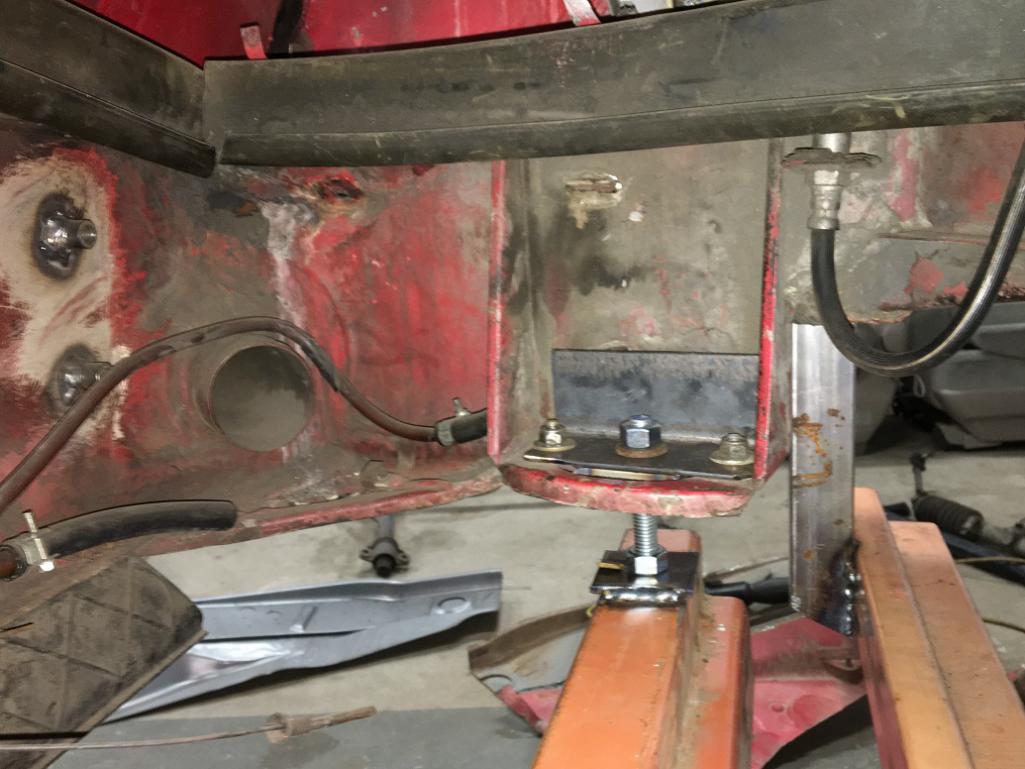
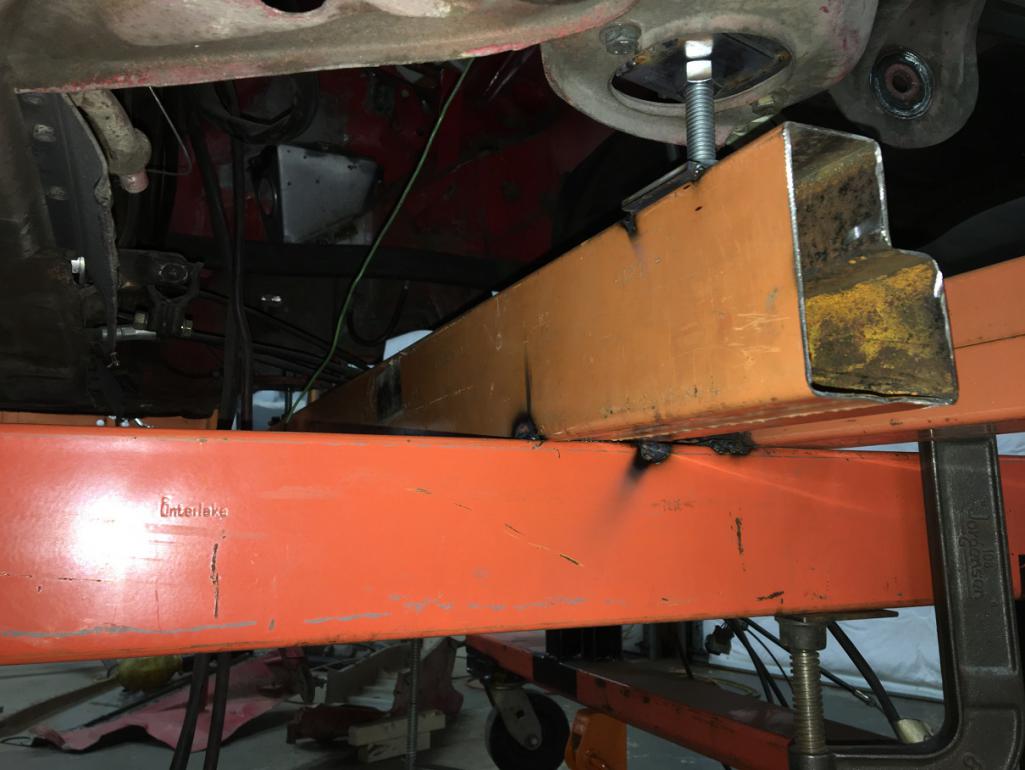
Yes, almost ready because bracing is the next important part! I built these using 1"x1"x1/8" square tubes and 3/4" turnbuckles.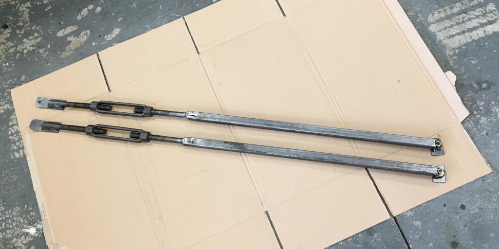
Now installed on the tub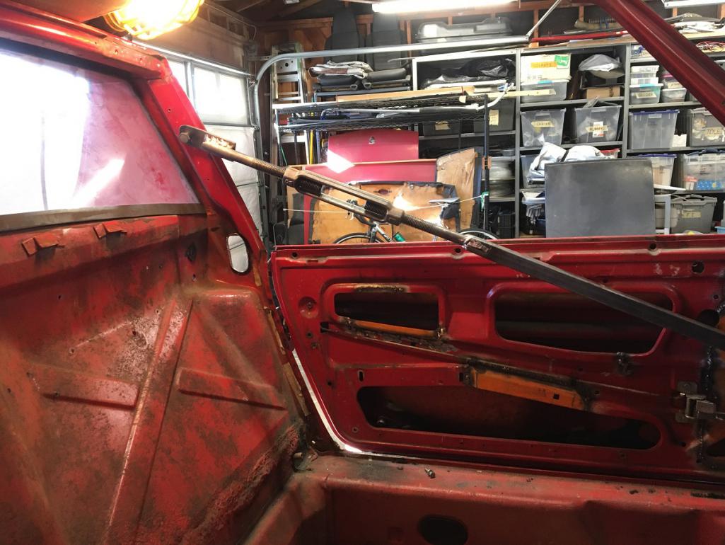
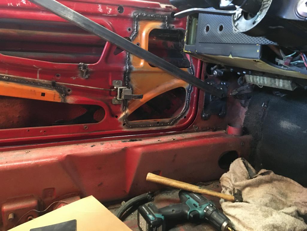
Then I decided to add another one on the bottom. Not sure it is needed, but anyhow, it is there... 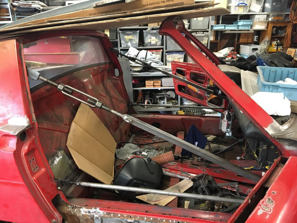
Note that all these braces can easily be removed by unscrewing the bolts at each ends. Also, doors are kept on the car and can open or close freely to ensure constant gap monitoring.
Posted by: Montreal914 May 29 2023, 10:30 AM
To address the rust on the driver's side long, I will need to remove the rear suspension outer console. In order to reinstall it, I need a jig to locate the mounting points.
I prepared a couple of 1/4" plate using the "L" piece that goes in the suspension assembly as a template for my holes.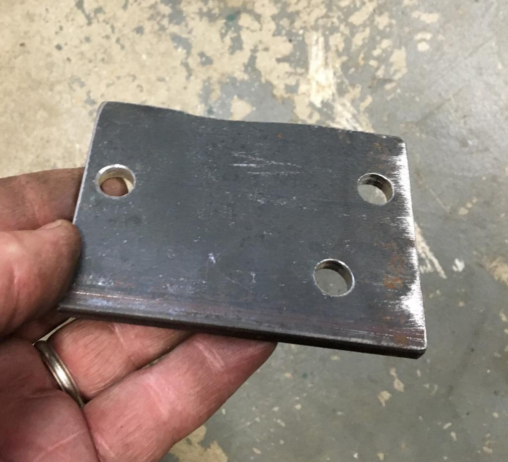
Once bolted to the chassis, I built a jig mounted to the Jigster. The cross beam has left-right stoppers, and there are also angle stoppers to the Jigster longitudinal frame as front-back locating point. The cross beam is then clamped to the Jigster. 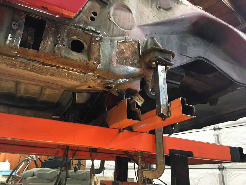
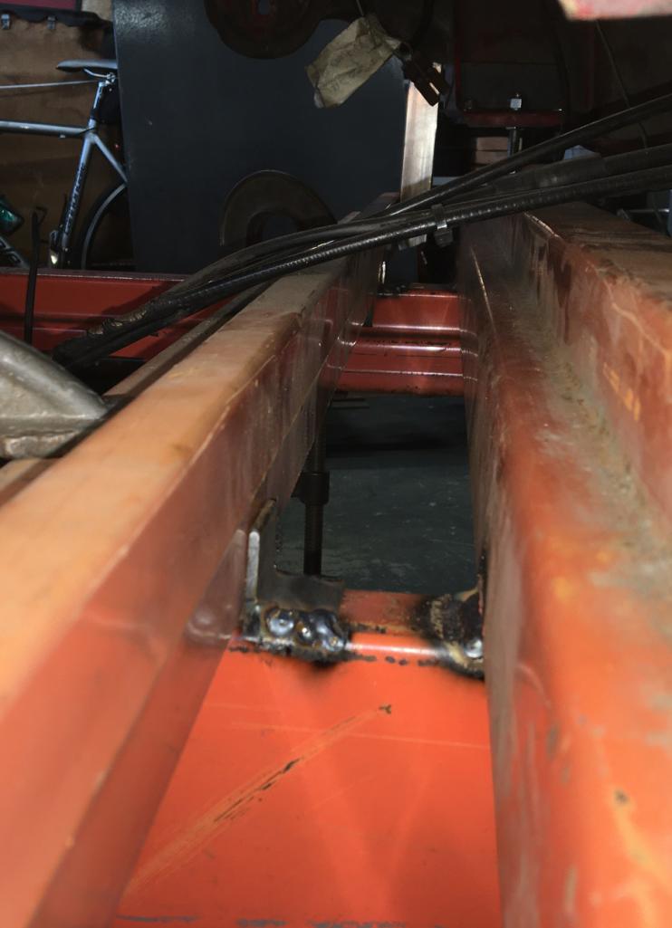
To remove the outer suspension point jig, I unscrew the six suspension bolts, Remove the large clamps, slide the cross beam with jig backward, tilt backwards, and remove. Important to note that I will not remove both outer suspension point simultaneously (driver's and passenger's side) so at least one of the two suspension mounting point will be on the car when one is removed as an added reference.
Next, I started dismantling the donor part I recently got from Vince. Anyone who has dealt with these rear suspension factory braces know how much of a pain they are to remove... 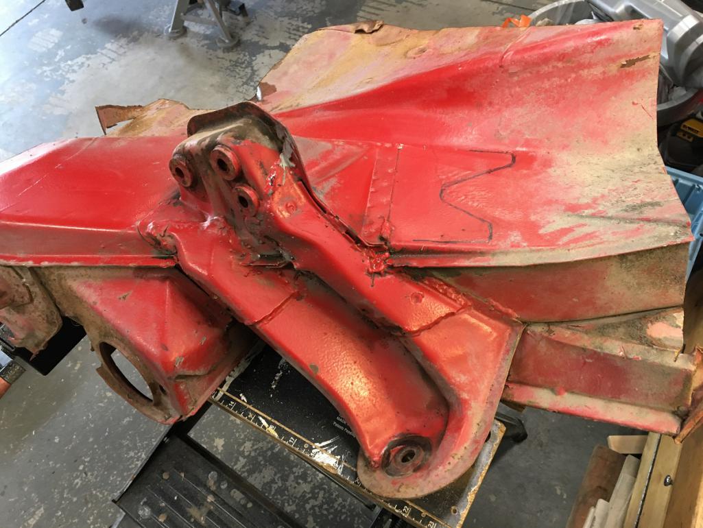
As if all of the perimeter welds weren't enough on the longer brace, there are 2 large plug welds to deal with... 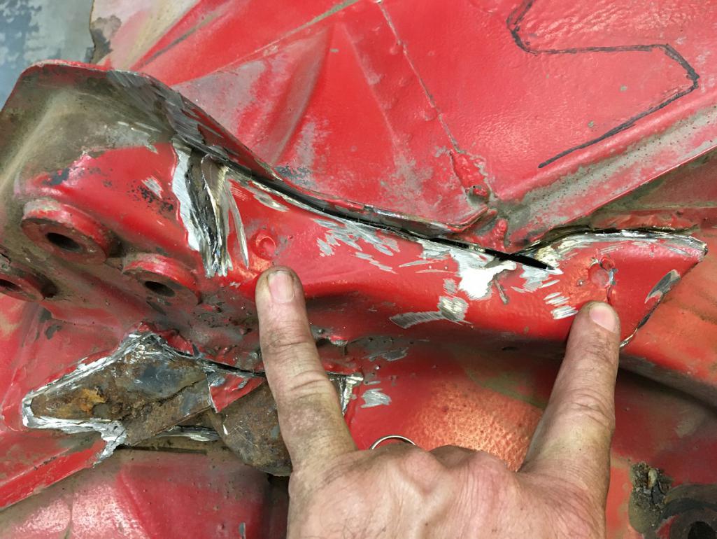
After spending about 3 hours of delicate grinding and drilling, I was able to separate the inner and outer portion of donor driver side rear longitudinal. 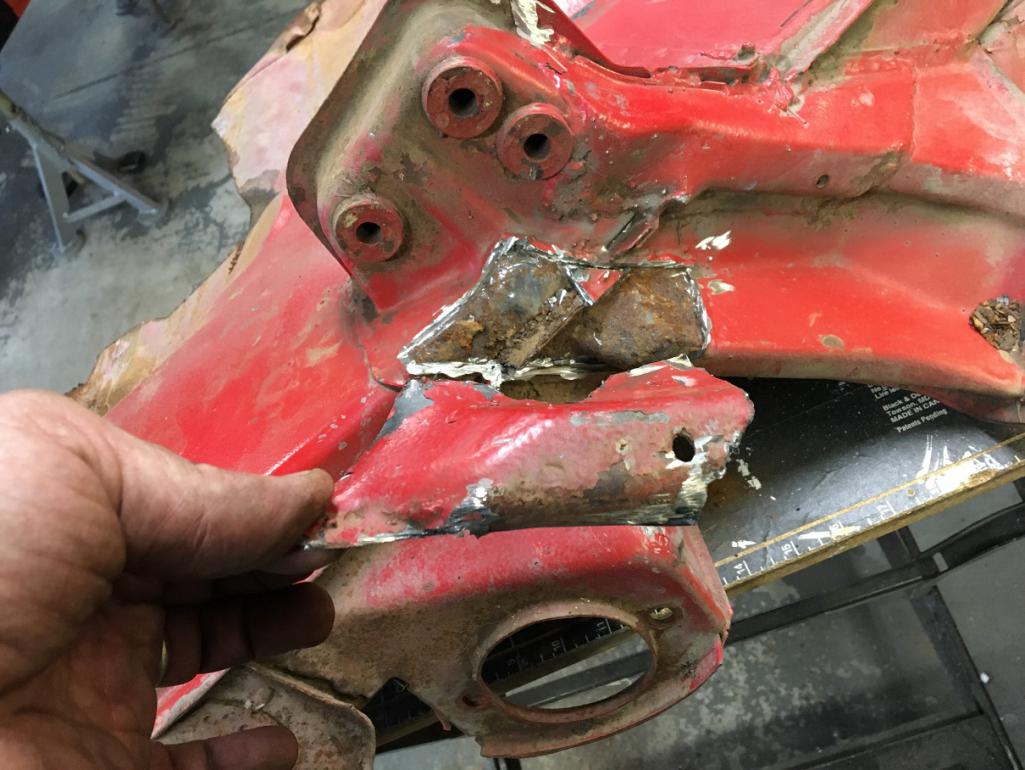
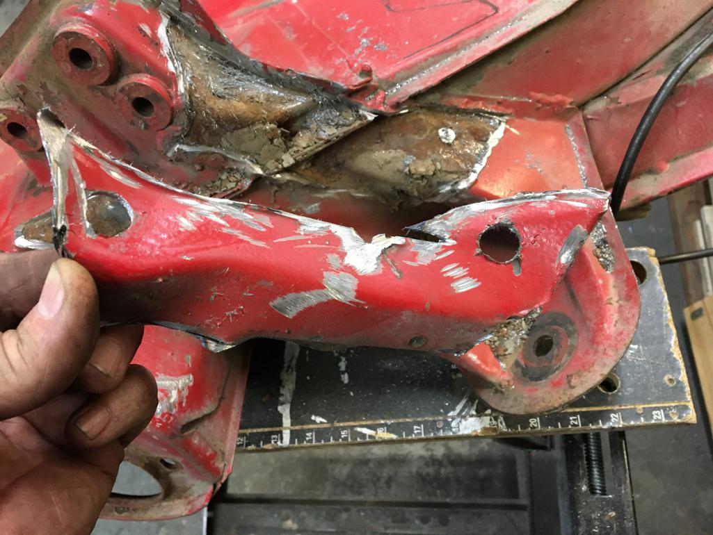

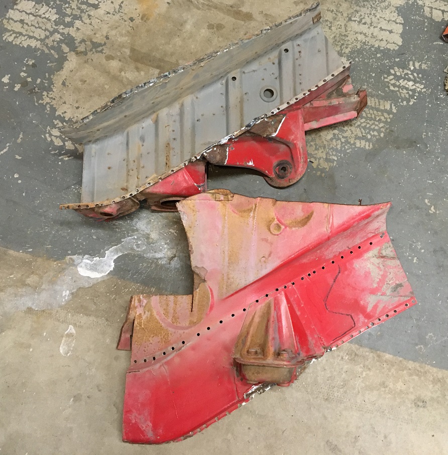
I am very happy with the condition of these old parts! All but healthy and solid metal!
More pictures in next post...
Not sure why this picture is repeated below...
Attached thumbnail(s)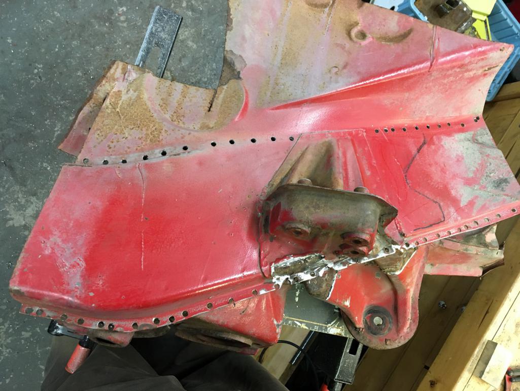
Posted by: Montreal914 May 29 2023, 10:54 AM
More pictures
Here is the back side of the outer long. This will be a nice replacement to the rusty area of my car. 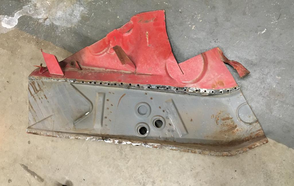
For those who aren't aware, unfortunately, the driver side of this part isn't available as a replacement part from Restoration Design of other vendors. So, I am very pleased with this finding!
Left is driver side, right is new RD passenger side. 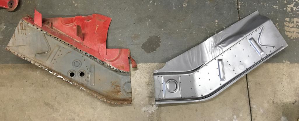
Looking at the port holes, I was able to take a few pictures to show the inside of the suspension console. These can be quite rusty at times, but this one is clearly in excellent shape. I will probably flush it with Ospho and spray some Eastwood chassis protection in it.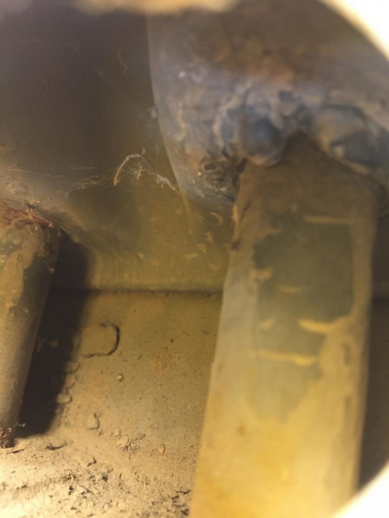
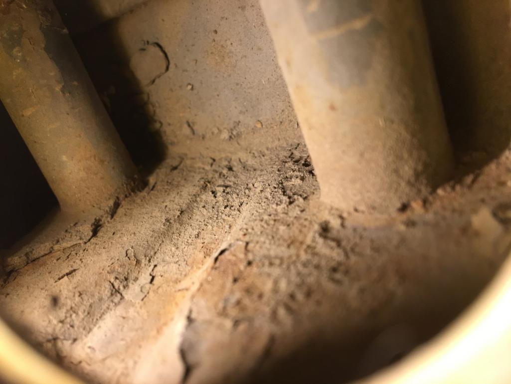
As a reminder, the reason I am going through all of this is to fix this...
From the outside, the metal on that elbow seems pretty solid.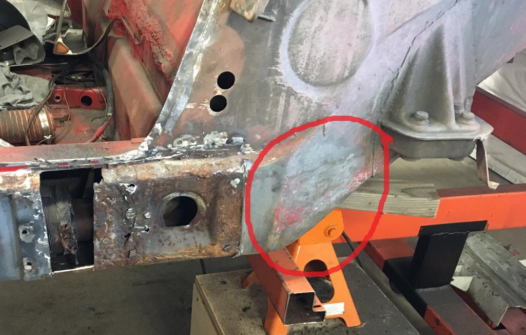
But once I looked into it, I found this crusty rusted and soft metal that I was able to punch through with a screwdriver near the suspension console area. That is a key structural area of our cars! 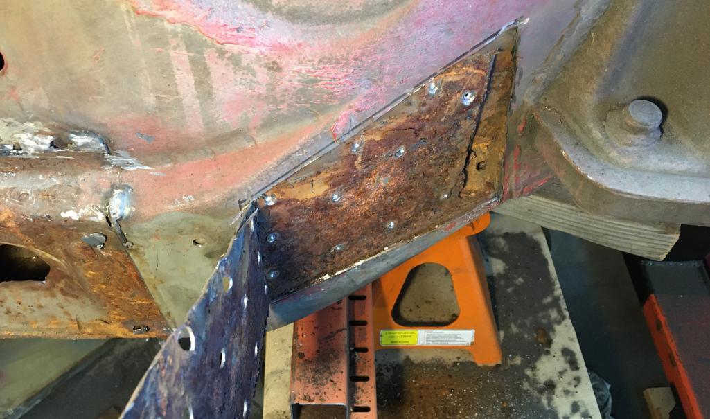
Posted by: nivekdodge May 29 2023, 07:05 PM
Holy toledo. You are going to town on that.
Kevin
Posted by: Mayne May 30 2023, 09:40 AM
Nice work! Are you going to coat the inside of your patch panels with something?
Posted by: 930cabman May 30 2023, 12:15 PM
This is great progress, thank you for documenting
Posted by: bkrantz May 30 2023, 07:08 PM
Nice surgical work. Keep going!
Posted by: Montreal914 Jun 20 2023, 09:04 PM
The quest for solid metal continues...
Clearly, both outer layers of the long from the jack point to the outer suspension console are compromised and will have to be removed.
So here is the plan marked in black. The inner fender will be cut above its junction to the inner layers. Spot welds will be drilled to free the outer layer from the inner.
The cut on the back end of the outer long will be done close to the suspension console. The plan will be to use the
Attached thumbnail(s)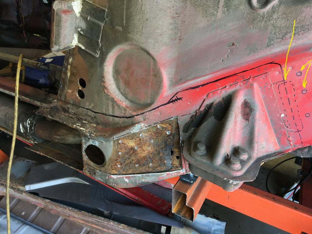
Posted by: 930cabman Jun 21 2023, 07:32 AM
Will it ever end?
Keep up the good work, there must be and end to it
Posted by: Montreal914 Jun 21 2023, 08:37 AM
Right? When will I get to solid metal??
I accidentally added the previous post as I was composing...
Back to the cut of this large piece...
The cut on the back end of the outer long (right in the picture) will be done close to the suspension console. The spot welds joining the tail end (V shaped) of the inner layer will be drilled. The plan will be to install the new piece using the inner layer as an overlap.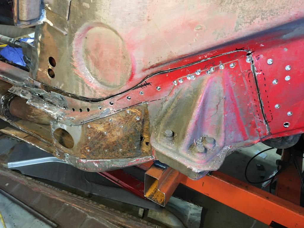
Here we can see the whole piece freed up. Notice the inner layer (V) extending towards the back. The new piece will be installed exactly like that and the inner layer will be plug welded to the outer layer creating a nice staggered ovelaping joint.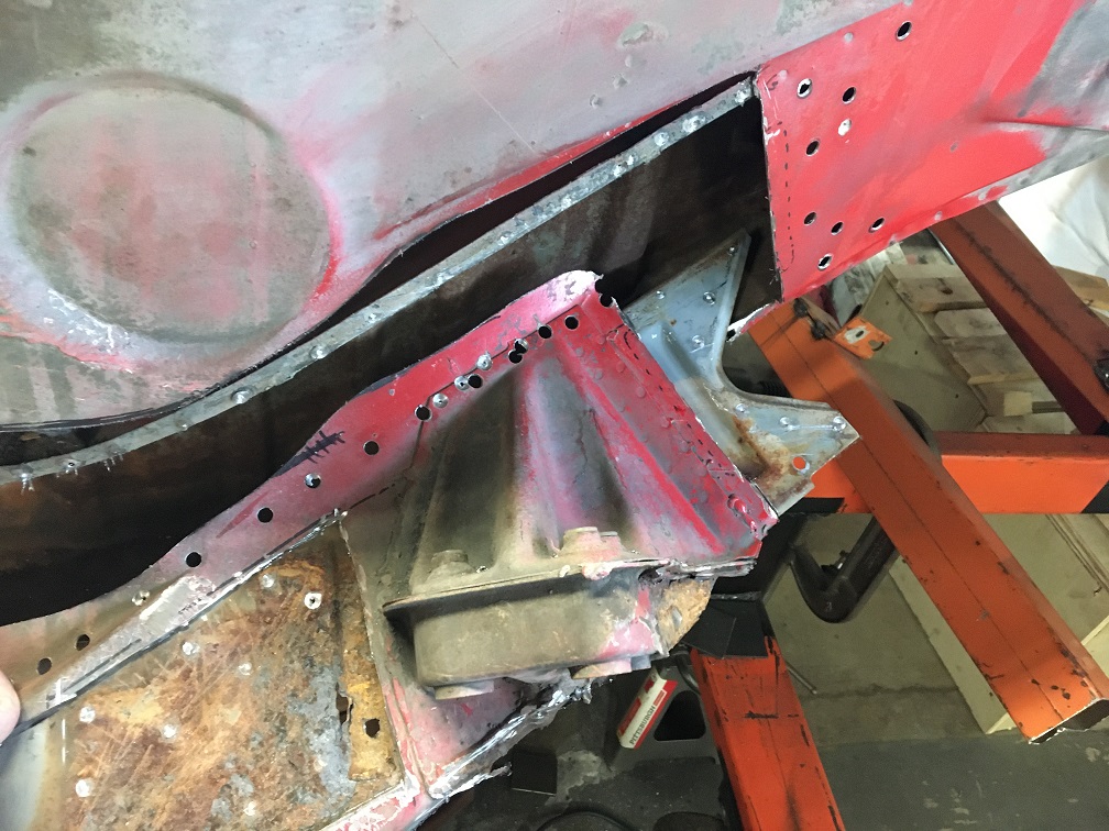
And here is the removed piece. Although the heavily rusted area circled seems small, I am convinced there is a lot more hiding. Did I remove too much material? Could this have been repaired without creating this opening? Maybe, but the outer suspension console would have needed to come out anyway. The benefit of removing the whole panel will be to inspect more easily.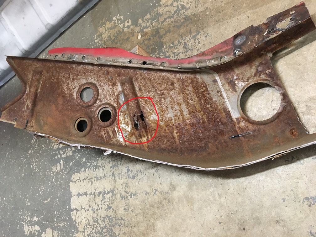
First, let's make a peek hole to see what color is the metal behind... I am definitely liking that nice primer gray color in the hole!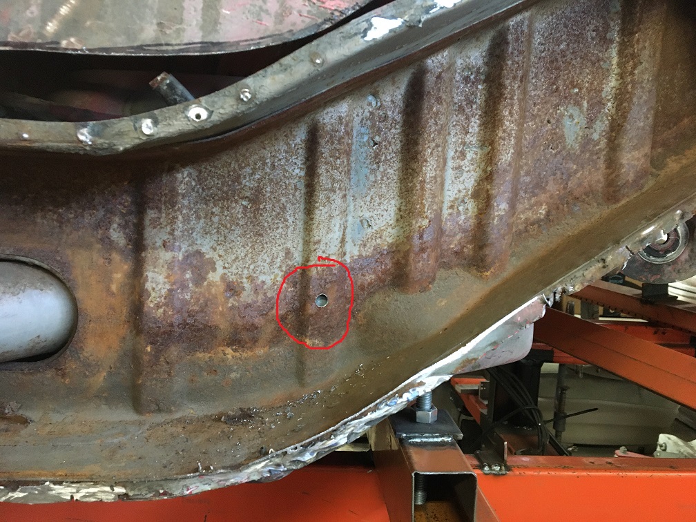
But there are other areas that aren't looking that great... 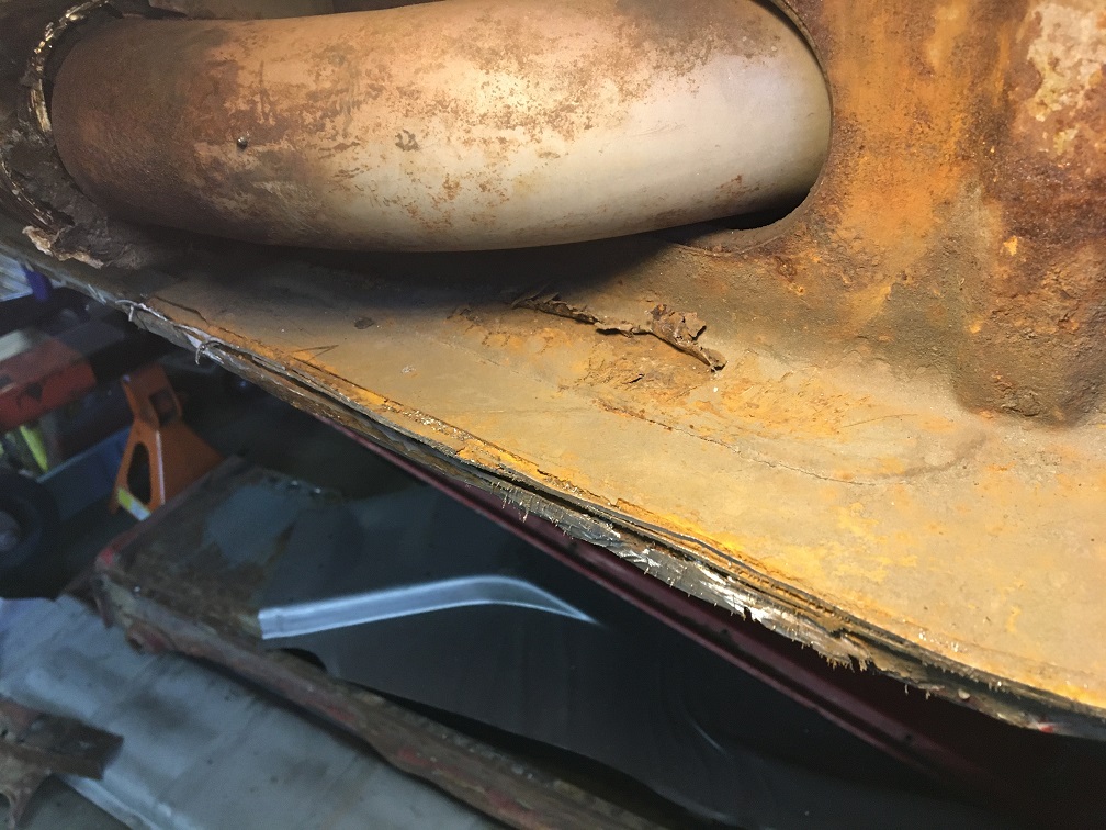
These bumps are always suspicious to me... Clearly rust has pushed the metal up in that area. Investigation will be needed.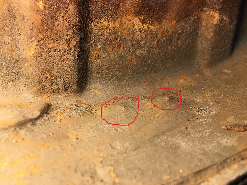
Time to chisel this weak metal off and see what is still good...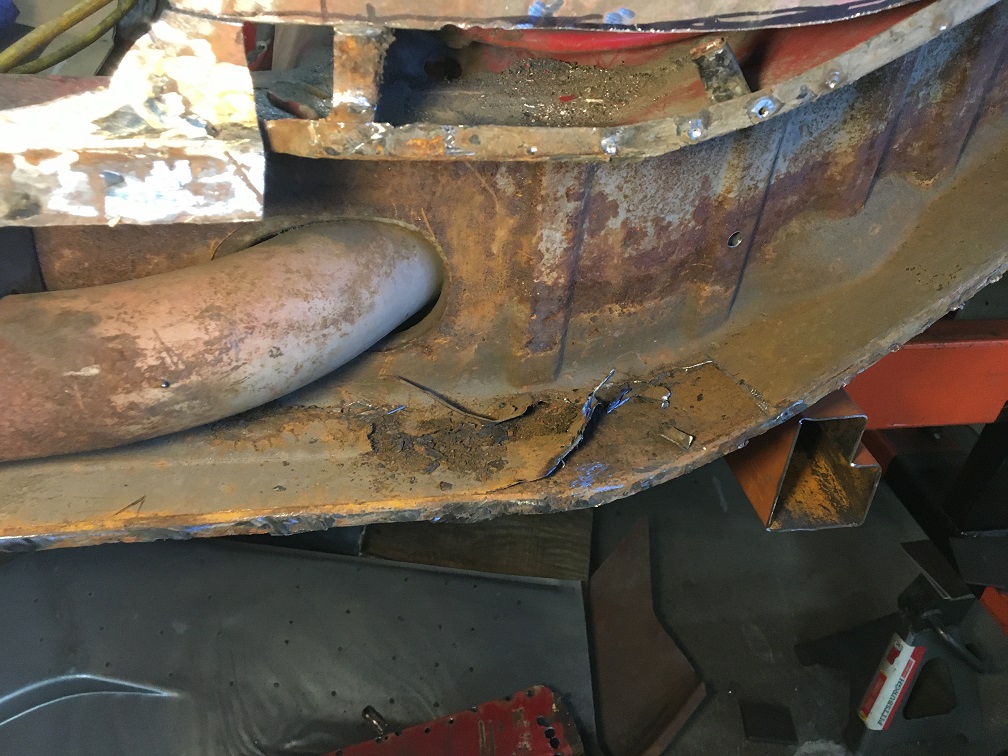
That led to finding weak spots also in the outside inner layer of the long. Again, in order to fully assess the situation, I need to remove more metal. That triangle with the donut will have to come off...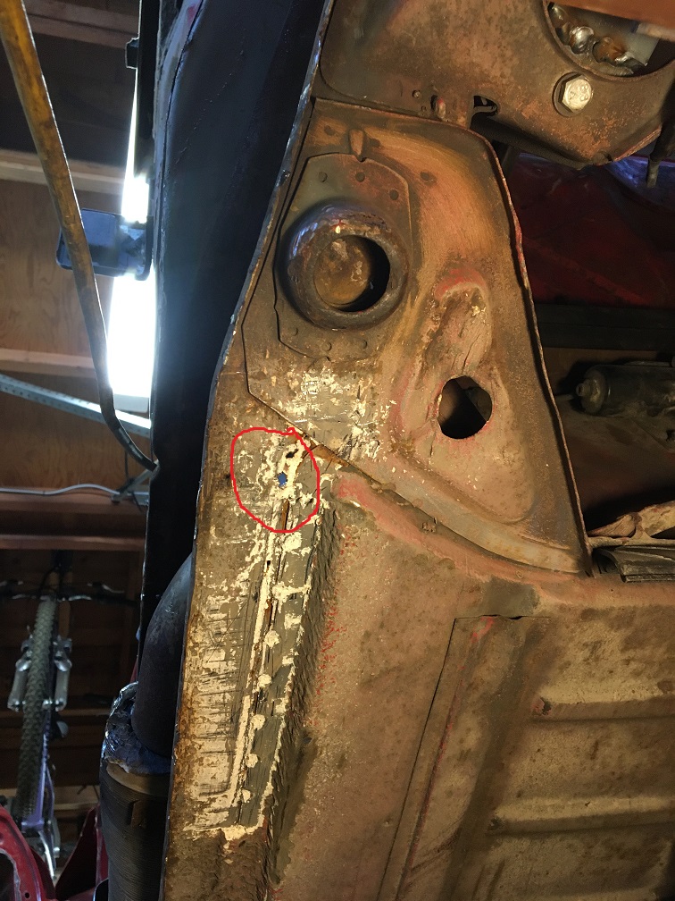
Out it goes... This part will be straightened and reinstalled after the long has been repaired.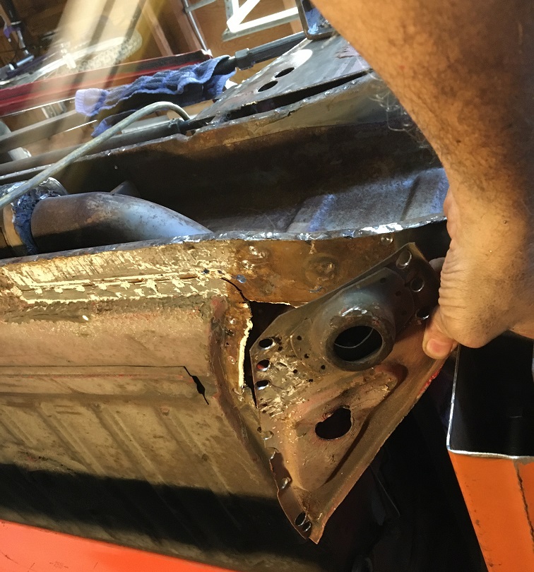
Ah!!! Rust, rust, and more rust... 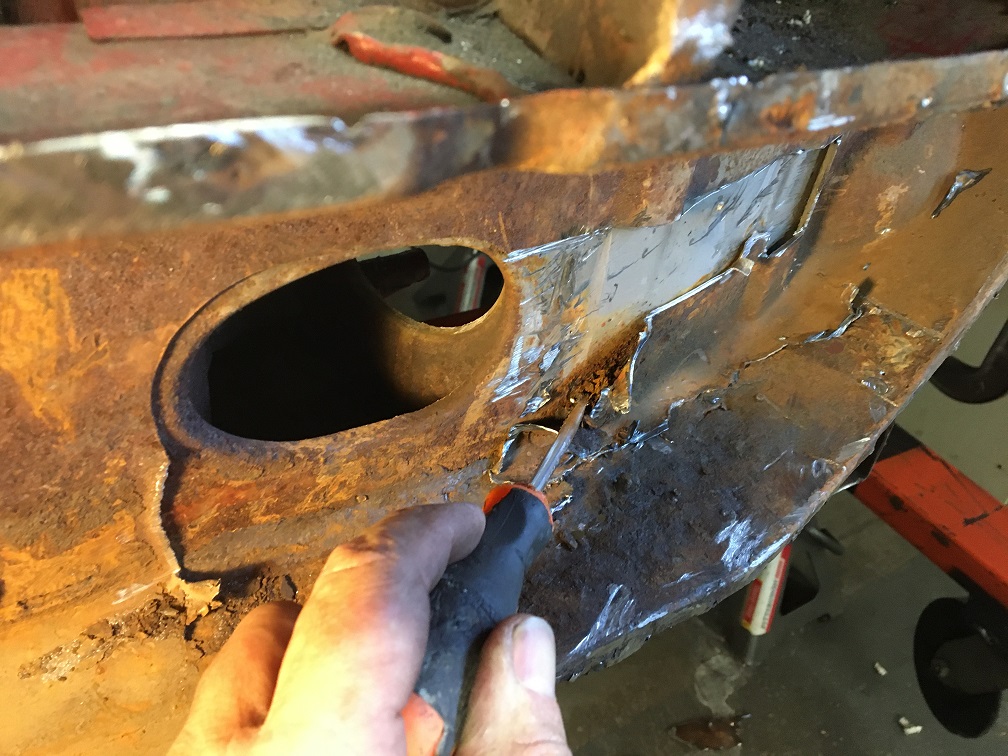
In the end, I removed the whole lower half of the inside inner layer (contoured in yellow), including the lower seat belt anchoring point. Notice the rust hole just behind it... While poking with the screwdriver, it easily went through... I am holding the last piece removed in my hand. All of this was progressively done. But at this point, I do believe the deep rust is ending and the good metal is finally there. I will treat the surface rust and the metal should be sound.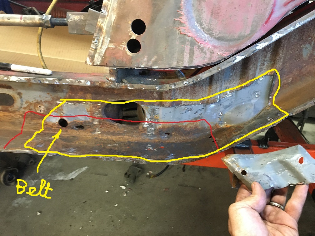
Next step will be to cut at the red line and rebuild the inside outer layer, then add the inside inner layer. Removing that red section will also means detaching that area of the floor, and the flanged lower firewall beam inner and outer panels. More fun to come!
Posted by: 930cabman Jun 21 2023, 09:30 AM
AT LAST, good metal
Like finding water in the desert (not really)
Posted by: Montreal914 Jul 13 2023, 10:59 AM
Next step, cleaning up the surface rust in the upper long.
So this is the situation now.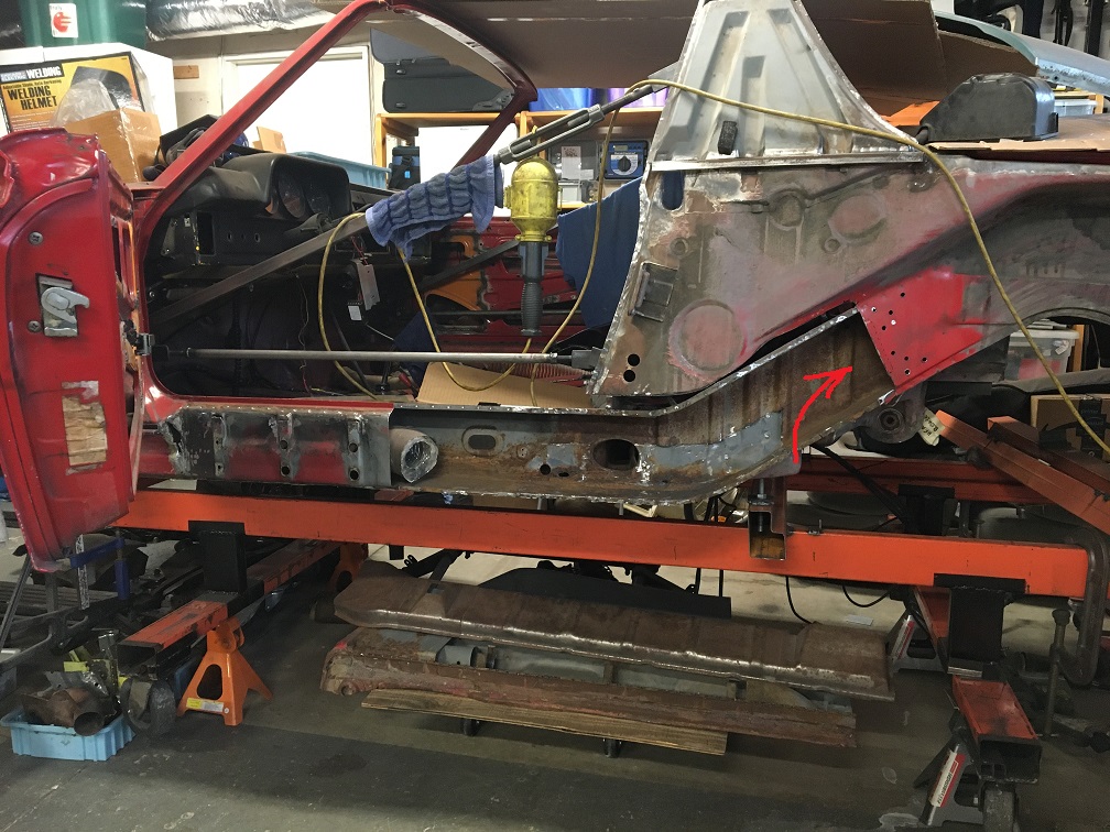
More specifically, I am looking at treating the surface rust in the upward portion to start with. Here! (Note that this picture was taken before I removed the Inside-inner lower portion shown in previous post.)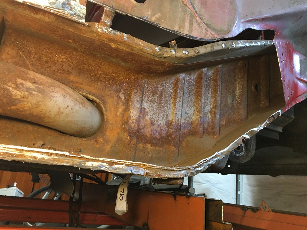
Inspired by @"Alain V." , I found online people using powdered citric acid mixed with water to dissolve rust. Looking at the amount of fluid I will need to soak some of these large parts, I decided to try it out! Dissolve 2 cups of citric acid with water in a medium pan at medium heat. On the side, fill a tote with 3-4 gallons of water. When powder is dissolved, carefully poor concentrated acid into tote. Now you have a cheap mix of rust dissolving solution.
After trying overnight with a piece I had, I was pleasantly surprise of how efficient this was. Then I used Alain's setup, got a larger tote, a $20 submersible pump, a hose, and a sprinkler head I had laying around.
This is the setup, spraying the citric acid in the long. I started from the top and gradually moved the spray head down.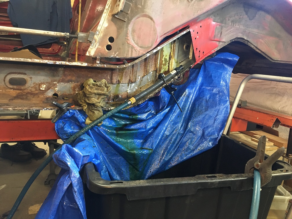
As you can see the upper portion of the long is now nice and gray, 50 year old metal renewed! Arrow is pointing at the fan spray pattern.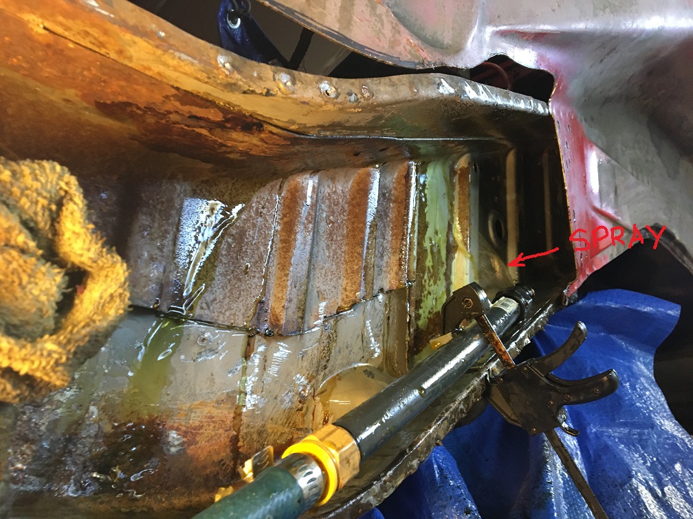
And a last one because this is so cool! 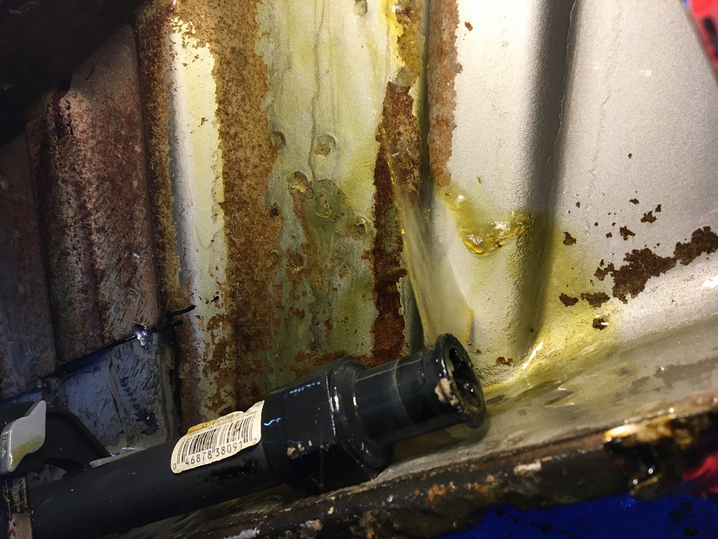
After a few days of progressively moving the spray head from top to bottom, I used another tote with a mix of water and baking soda and flushed the whole area for 1/2 day to neutralize the acid. @http://www.914world.com/bbs2/index.php?showuser=20880 , Next, I plan on using some Eastwood rust encapsulation that I will brush inside. Then, after having closed back the long, I will use the Eastwood inner chassis spray with the flexible hose and nozzle, or spray cavity wax.
With all of this done, we can now see what was hiding below these bumps (tip of the iceberg) I had noticed a while back. Here is the refresher picture of these bumps:
And here is what was under that bumpy inner layer... 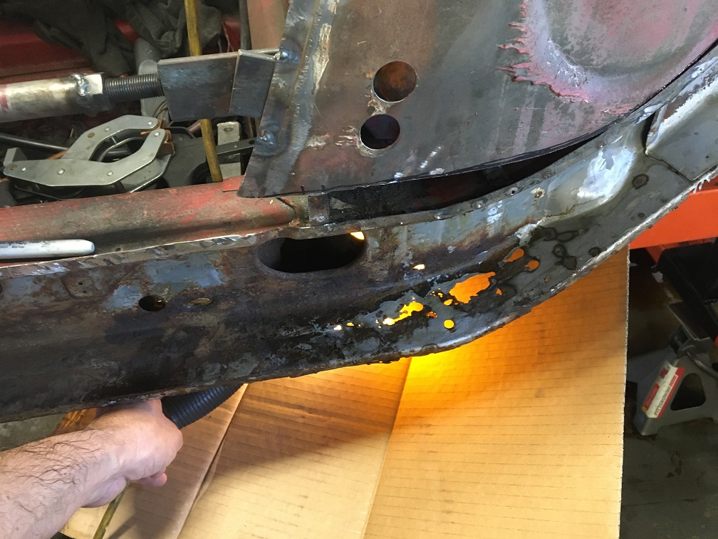
So I now know what will need to be cut out of the lower part of the inner long. Time to look at the donor parts I actually have to see what can be used.
First step, dismantling the factory assembly by drilling every spot weld and separating every part...
After splitting the outer from the inner of the donor parts a few weeks ago, here is what have. To assess if the metal both of the inside-inner and inside-outer can be used, I need to dismantle this whole assembly. So the engine mount needs to come off and the inside suspension console too. Hopefully I can achieve this while saving these parts. I don't think I will need them, but maybe someone here will.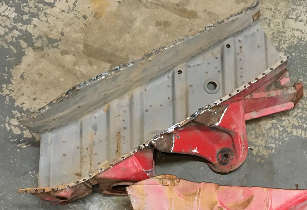
And here is the engine mount removed. There is some rust but it is too early to fully assess at this point. As you can see the separation work of the inner suspension console is well on its way.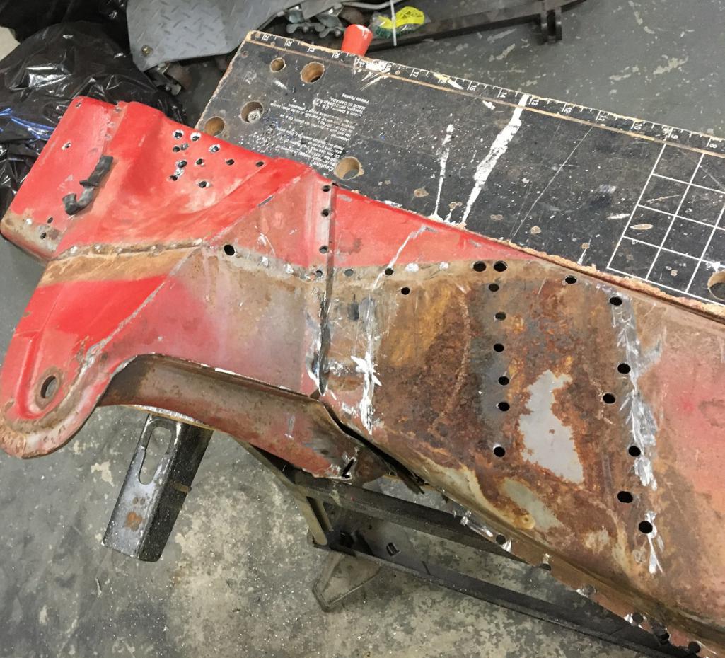
And here is the inner long free of all attached components. I am interested in this portion circled in red.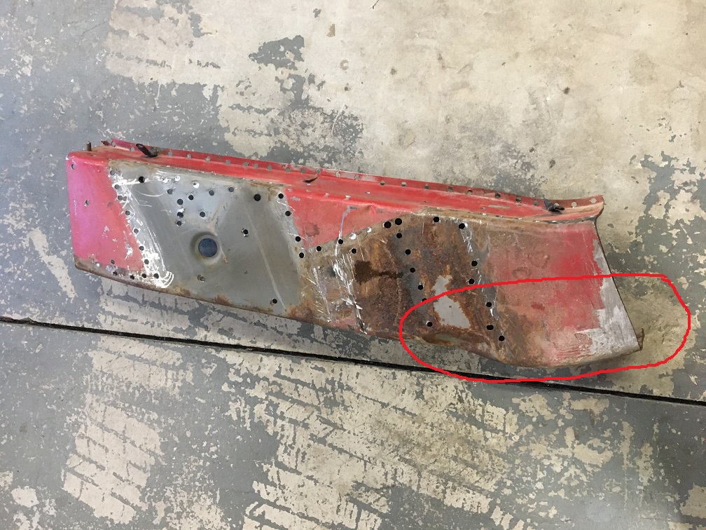
That being said, I am actually interested in both the outside-inner (seen here ^^^) and the inside-inner (seen below). So I will need to separate the two onion layers... Here we can see what I am looking at using. Fingers crossed for the metal to be in good shape at the interface. As we can see I have stated to separate the two layers.
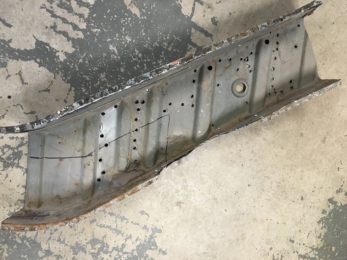
More to come, stay tuned!
Posted by: Alain V. Jul 13 2023, 06:07 PM
Something really satisfying about dissolving rust and finding clean metal. Looks like you are making good progress.
Posted by: 930cabman Jul 14 2023, 07:37 AM
Very cool process
Posted by: Montreal914 Aug 6 2023, 11:55 AM
Some progress to share:
Before continuing the previous post with the preparation of the repair piece for the outside-inner lower elbow area, I went on and actually cut out the bad metal, to really establish the repair piece I will need.
Here is the situation: The black sharpie line (circled in red) is where I have decided to cut and remove material.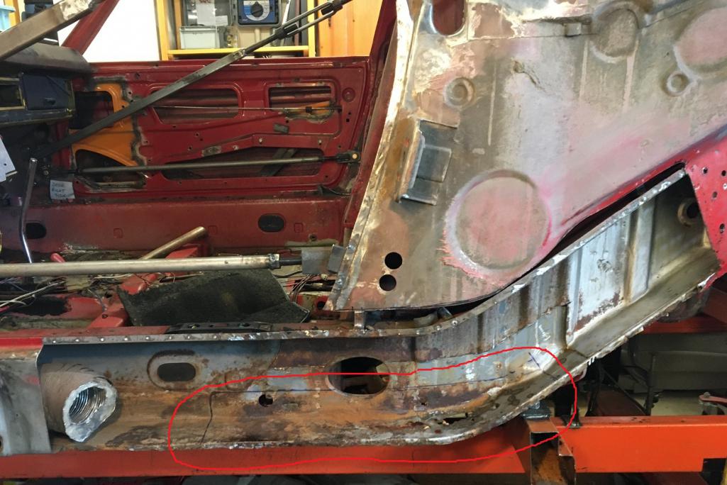
There are a few things to consider when removing this piece. First the floor is spot welded on the underside of it, then the two vertical walls of the firewall are flanged basically on either side of the oval port. Then, at the right end, I am actually cutting half way into where the engine mount is attached (embossment). I chose this location for a couple of reasons;
1- I wanted to see the engine mount metal behind it,
2- The engine mount will serve as overlapping layer.
Based on what I have seen in removing the engine mount on my donor part, there is actually a gap between the engine mount and the embossment in the Outside-inner long metal. The plan is to add a metal layer to do an overlap on that joint. Plus the engine mount itself is an overlap.
To preserve the various metal joining to the metal I am removing, I will be cutting and grinding it away, keeping the flanges intact and ready to receive the repair piece. Here is the beginning of the process on the left side: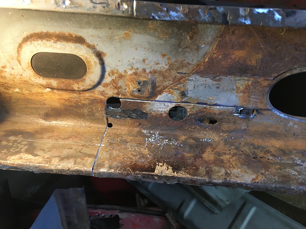
And here is that metal removed: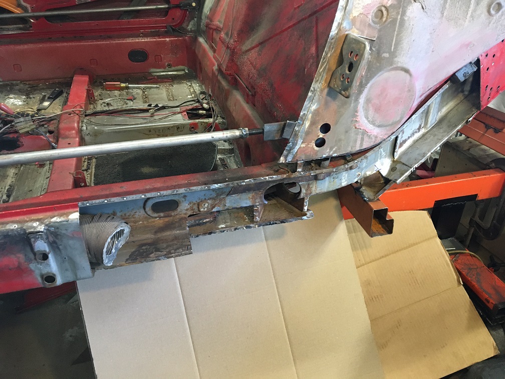
Closer view where we can see the two firewall flanges, the lower half of the engine mount (right end), obviously the floor, and the flange of the e-brake cable guide in the cabin. All of these flanges are nice and solid and will be the welding surface as I plug weld the repair piece in (minimizing upside down welds). 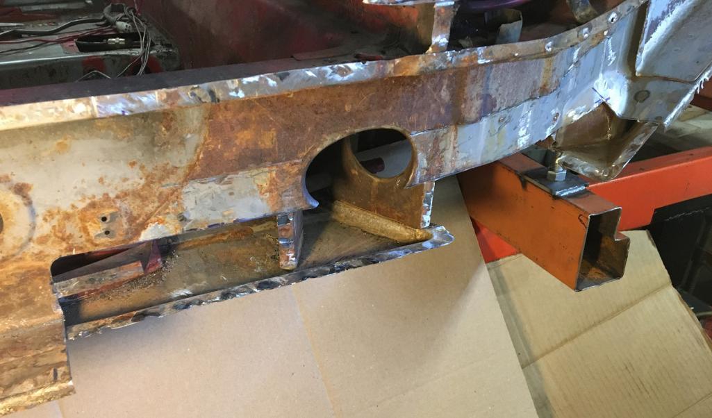
Now, time to prepare the repair piece.
As show, in the last post, I need to dismantle the various sections of repair parts I have, assess their condition, and make a repair piece. The donor long I got was cut to the right of the jack post, basically behind the firewall. Therefore, the repair piece will have a vertical weld roughly in the middle.
Here is the rear half of the doubled layered repair piece: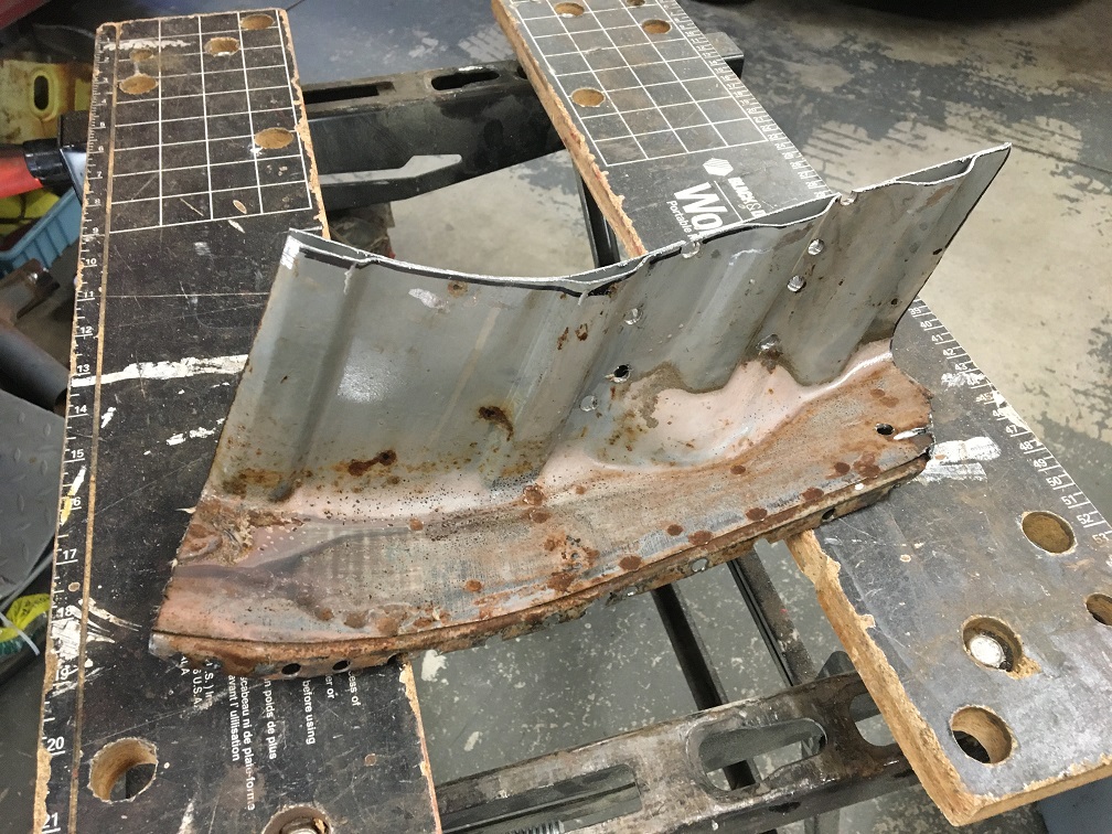
Since I will need both inner and outer layers, I had to drill all the spot welds to separate them. This works well, but unfortunately leaves one of the two pieces look like swiss cheese. We'll look into that later.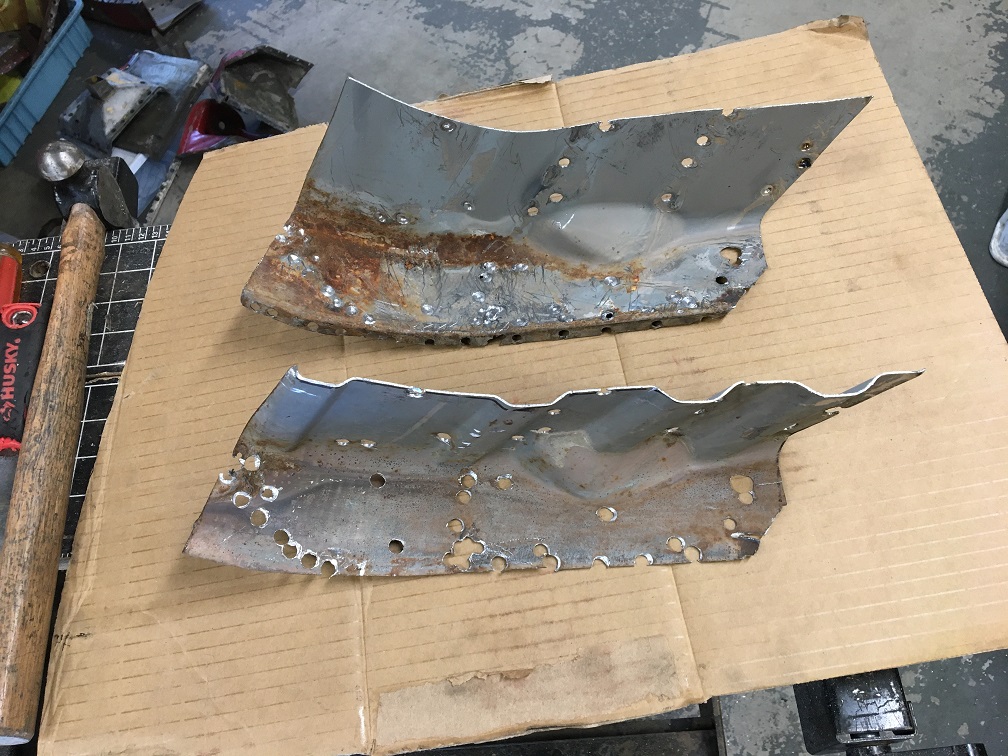
Overall, these two parts are pretty rust free and I am confident can be used as-is after getting de-rusted in citric acid.
Now looking at the front half donor parts, same process; drill the spot weld to separate the two layers.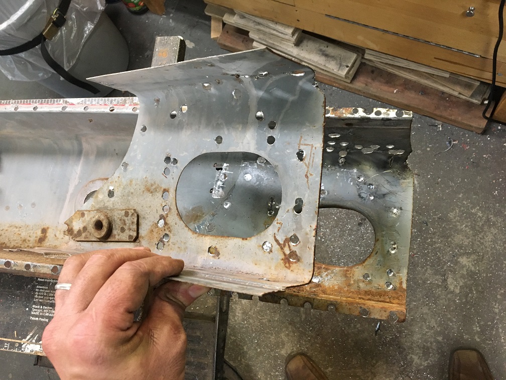
Unfortunately, these are not as good as the rear half's. Let's see what de-rusting will reveal...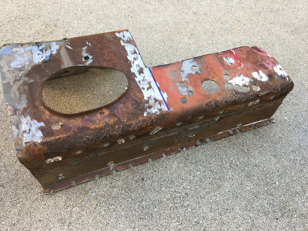
After a couple of days soaking in citric acid, here is the result. The rear end of it is a little pitted but not major, The front end (with the hole for the safety belt) is compromised in the fold and will need to be addressed (circled in red). 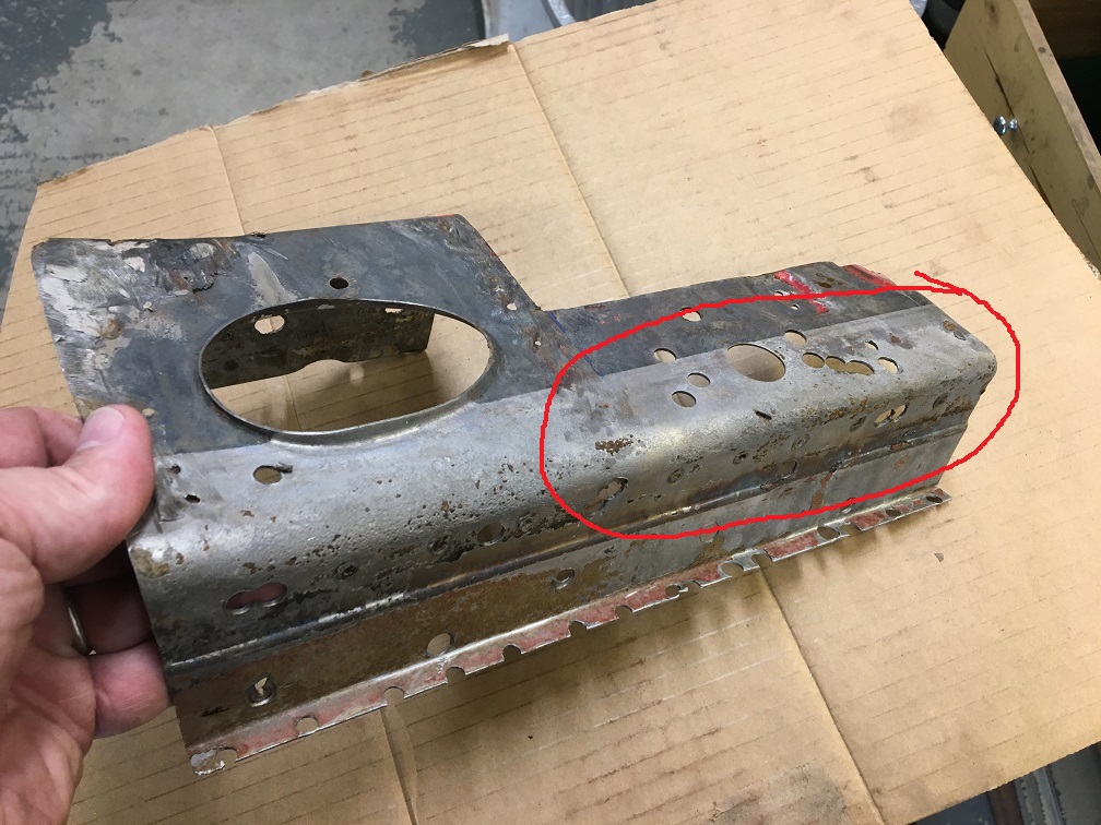
Most of the rest of the donor long is heavily pitted in the bottom fold except a section that I was able to cut out of. I will use this section below (black sharpie) for the repair piece.
What I am after is having the step detail of the lower part where the floor attaches to the long (red arrow). 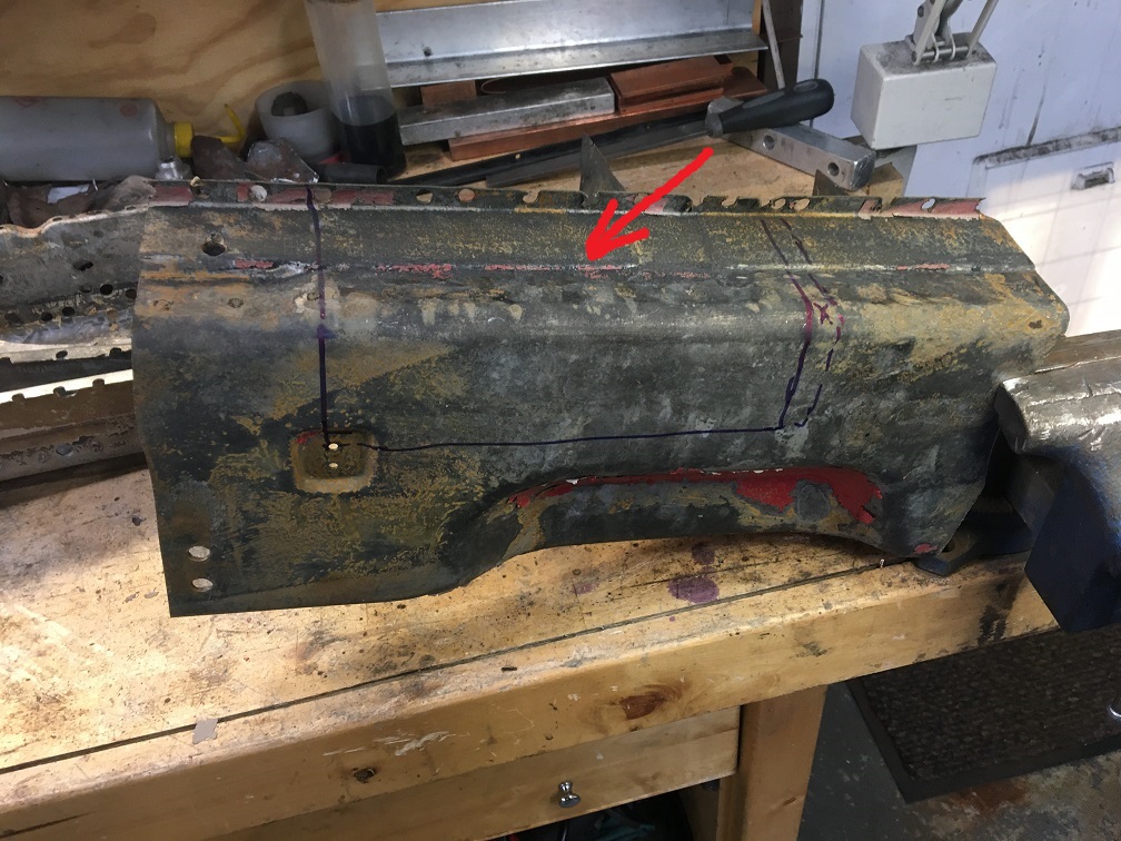
So here is the plan; joining the retrieved good part on the right to the left half with the oval hole. Not only will this replace the heavily pitted metal, it will also take care of a lot of swiss cheese. The hole for the seatbelt will be done before joining the two. 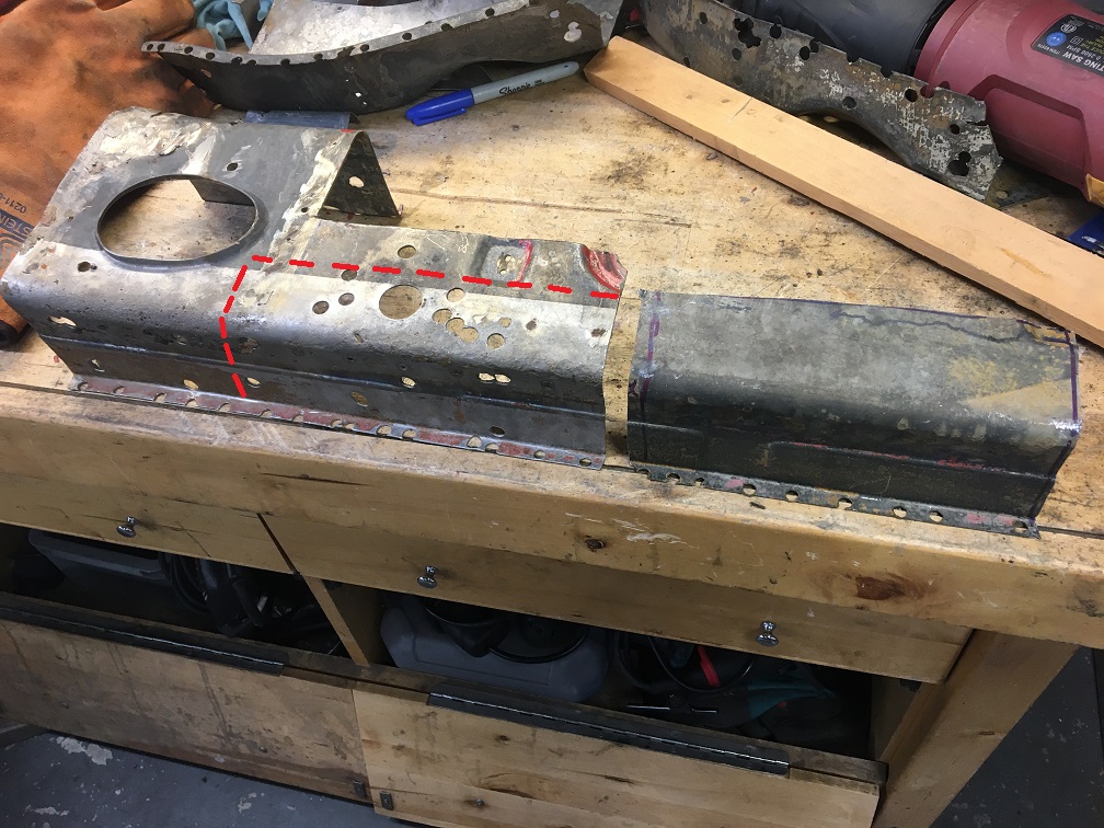
To be continued in next post...
Posted by: Montreal914 Aug 6 2023, 02:41 PM
After carefully trimming both piece, I set them in this contraption to join them straight. Hole for the seat belt in there now.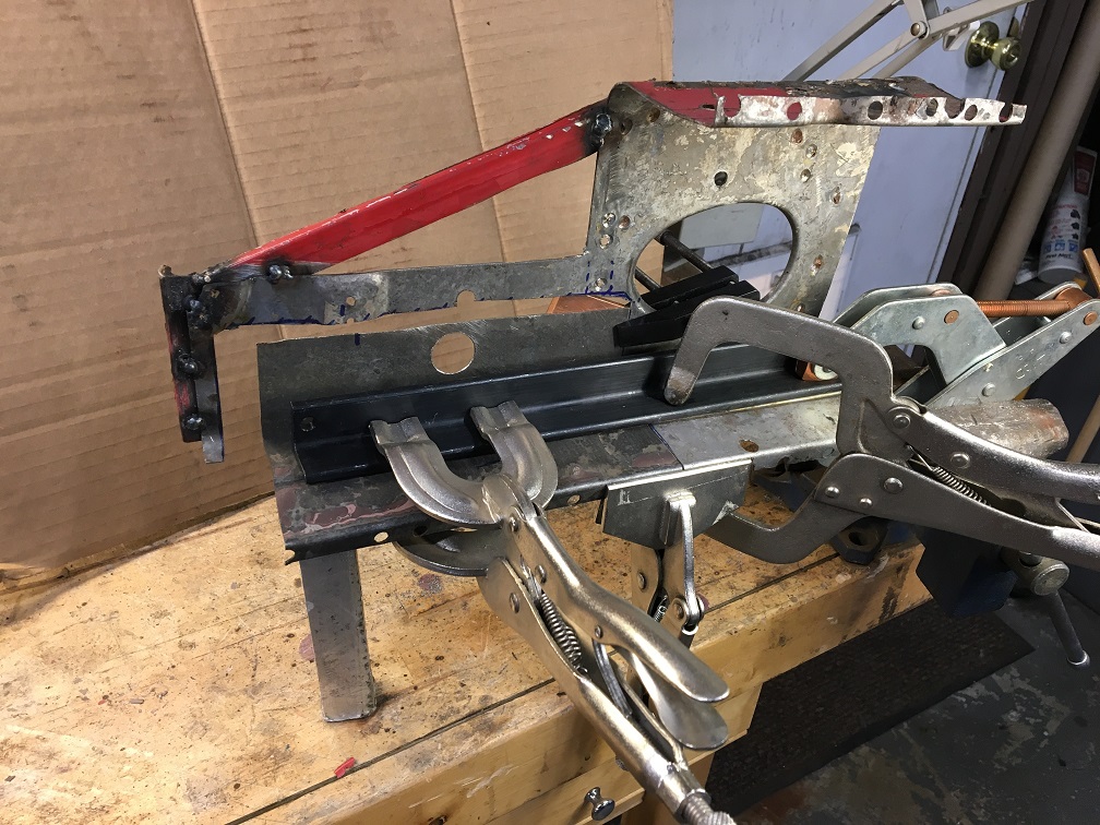
And the back side. Notice the copper plate to absorb the heat. A similar plate lies under the bottom surface too.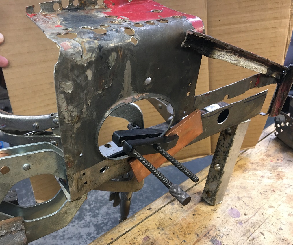
Now the two pieces are one. We can see some of the pitting on the right piece, not ideal, but not too bad. I may try to reinforce this. Here i am plugging some of the holes created by the spot weld drilling.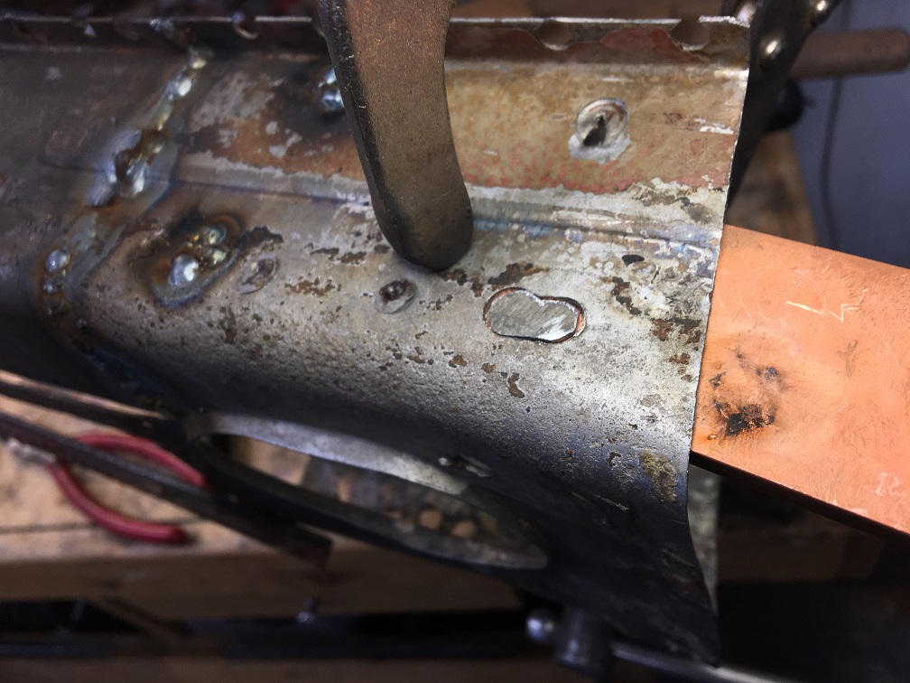
Moving on to attaching the rear section of the repair piece. Making progress! 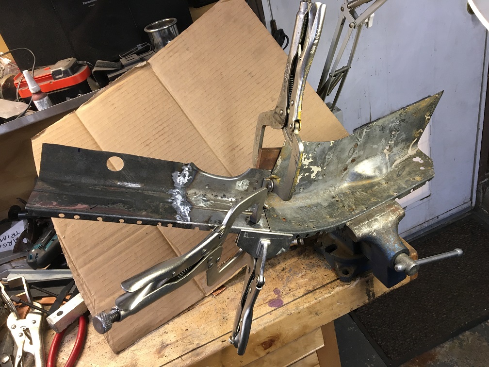
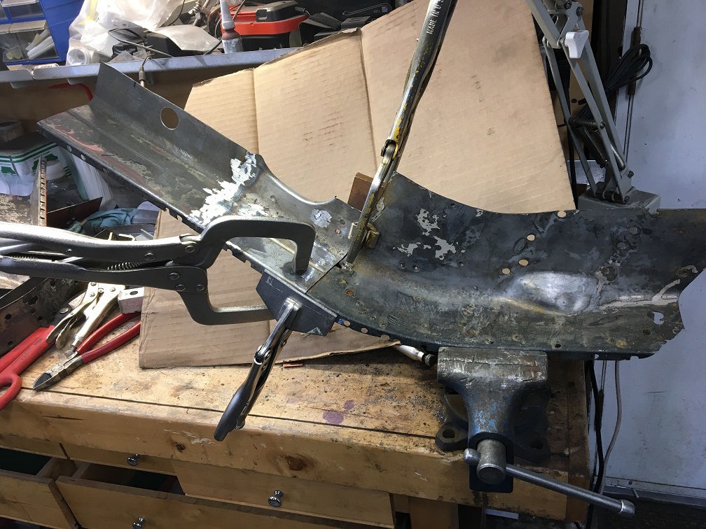
Finally, three becomes one!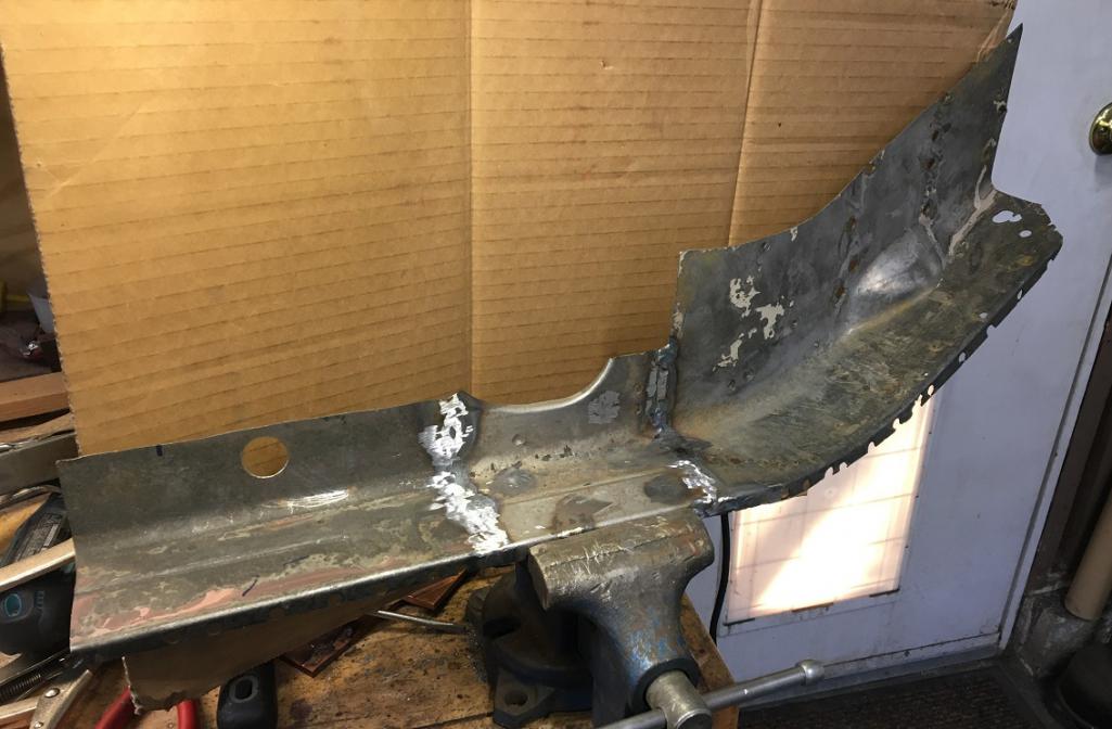
And after a lot of back and forth trimming, the part is now 95% ready to be installed.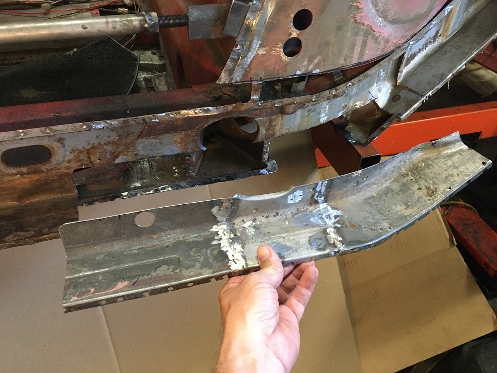
Fit is almost perfect, just a little bit of fine tuning and it will be ready. 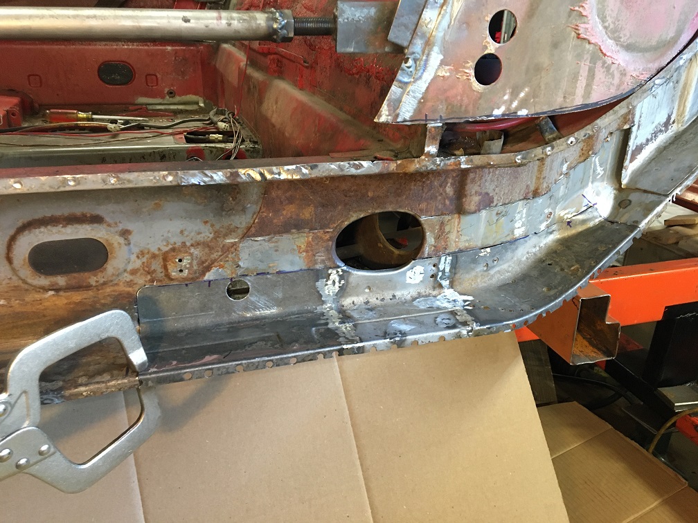
More to come soon!
Posted by: nivekdodge Aug 9 2023, 08:31 PM
You are kickin a and taking names!!!!!
Posted by: tygaboy Aug 9 2023, 10:08 PM
Super nice job you're doing. Great fit-up on those panels. 
Posted by: 930cabman Aug 10 2023, 12:09 PM
Prior to welding new sections in place, have you been double checking the alignment of your pickup points? Looking at your jig, it appears somewhat light gauge. A quick double check will let you know all is good before new metal is secured in place.
You don't have to ask why ...........
Posted by: Montreal914 Aug 10 2023, 01:31 PM
Prior to welding new sections in place, have you been double checking the alignment of your pickup points? Looking at your jig, it appears somewhat light gauge. A quick double check will let you know all is good before new metal is secured in place.
You don't have to ask why ...........
Although it looks like I am ready to weld this in, I am not there yet. Yes I will measure everything and also temporarily reinstall the fender to check door gap.
Each little step is at slow pace where subsequent steps planning are part of every move.
Think think think, act, trying to minimize the “ah darn” moments.
Posted by: Montreal914 Aug 10 2023, 01:34 PM
Super nice job you're doing. Great fit-up on those panels.
Thank you! Coming from you
I appreciate the compliment. The file is one of my preferred tool…
Posted by: TRS63 Aug 11 2023, 06:21 AM
Taking time to get the perfect fit is key to quality work. Well done
Antoine
Posted by: tygaboy Aug 11 2023, 07:12 AM
Prior to welding new sections in place, have you been double checking the alignment of your pickup points? Looking at your jig, it appears somewhat light gauge. A quick double check will let you know all is good before new metal is secured in place.
You don't have to ask why ...........
Although it looks like I am ready to weld this in, I am not there yet. Yes I will measure everything and also temporarily reinstall the fender to check door gap.
Each little step is at slow pace where subsequent steps planning are part of every move.
Think think think, act, trying to minimize the “ah darn” moments.
@http://www.914world.com/bbs2/index.php?showuser=24690 Antoine is far more concise but if I may:
HEY EVERYONE! The above bolded words are what make the ALL difference between an OK job (or worse) and the quality result @http://www.914world.com/bbs2/index.php?showuser=12023 is achieving. Ask me how I know! Sooooo many times I've wanted to make progress and had a "that's going to be fine, it's close enough" attitude, only to complete a step and be disappointed in what I'd just done. Then I was left building off of what wasn't as good as I'd hoped.
So I want to give a big
to @http://www.914world.com/bbs2/index.php?showuser=12023 for making this point. It's the one thing that makes the biggest difference for me. If I don't take the time to fit the material properly, I won't get the result I want. If I can't get into a (reasonably) relaxed, comfortable position, the weld isn't going to be as good. People poke at me for doing things over and over again and this is one reason why I was doing that: my process wasn't working.
I just redid (!) the rear panel on my LS car and was sending in-process pics to @http://www.914world.com/bbs2/index.php?showuser=3898 Robert. He commented about how fast I was able to crank out the project. It was because I spent a lot of up-front time thinking, planing, wondering, checking. He saw the execution, not the "pre-work". In the past I'd have just gone for it. Fun maybe, but not effective.
That said, I have a LOT left to learn - and always will. But I'm telling you, our friend here has nailed what I've come to believe are THE most important skills: patience and planning.
Great job and thanks for calling out your model for success!
OK, rant over. Back into the shop!
Posted by: Montreal914 Aug 11 2023, 10:23 AM
@http://www.914world.com/bbs2/index.php?showuser=19241 WOW!
I guess I have self set my bar high now... I will have to keep it up because the pros are watching and will give me bad review if I don't...
But seriously, I wouldn't be able to tackle any of this without the high quality build threads and the detailed information we can find here. Thank you all for this generous boost, now I am fired up to get busy on the build!
Posted by: tygaboy Aug 12 2023, 07:52 AM
@http://www.914world.com/bbs2/index.php?showuser=12023 - One last comment about how critical I've found the patience and attitude thing and I'll stop clogging your thread. You may have seen my post about visiting the Singer factory last year:
http://www.914world.com/bbs2/index.php?showtopic=361827&hl=Singer
For a more complete summary, read post # 8 but for thouse without patience  here's the short version, one I try and live by, about acceptable variance:
If Singer is +/- ZERO, going forward at the Red Barn, it's +/- less than yesterday!
Powered by Invision Power Board (http://www.invisionboard.com)
© Invision Power Services (http://www.invisionpower.com)