Printable Version of Topic
Click here to view this topic in its original format
914World.com _ 914World Garage _ Defrost fan rehab and rebuild thread (fresh air fan)
Posted by: DRPHIL914 Jan 21 2021, 08:55 AM
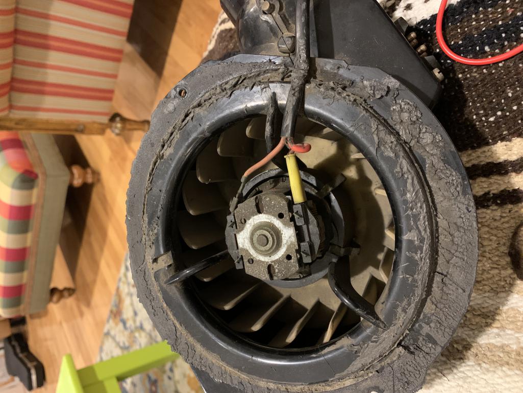
I have been dealing with this for 12 years, a non-running defrost fan. i even pulled this out 2 years ago and rebuilt it with new flapper seals and main body seal then made sure fan turned but didnt bench test the motor or resisitors, so as a result it still does not work properly. i will be documenting this because 914rubber and Mark will soon be putting together a kit for this that includes all the hardware seals and even a motor i believe, BUT i still have problems and questions!!! so i am starting this thread to get information on diagnosing the common causes of it not working and how to fix it, and then document the rebuild and replacement of the motor, fan, resistor and maybe the control unit in dash. Others have documented the reinstallation of the fan and the cables so i will not duplicate that. and we may want to link other threads hear that have done that as well.
Mark is sending me a kit soon, so while i wait for it, i will have to get some more information about the wiring and resistors function and how to test them .
I had this out last week and tested 3 different control units due to thinking that my issue was a control issue, because it runs on one speed, #2, and anything else does not work and it will then throw the fuse. most assume this would be caused by bad slider unit but i tested 3 of them and 2 are like new with no wear on the sliders , still same result. so i am suspecting the resistors /plug aparatus .
If anyone has done this and cares to share how to examine and test that for proper function, lets start there.
Resistor function, which lead is which and examination of the control units
I will take pictures of mine tonight and post those soon. once this figured out and fixed i will do a full step bystep on reassembly too.
Looking for lots of help and input on this, thanks!!!
Dr. Phil
Posted by: Superhawk996 Jan 21 2021, 09:43 AM
Not trying to be a jerk here. But I keep seeing a pattern in the forum when people are stuggling with electrical issues.
Rule #1: Don't assume anything
Rule #2: You MUST have a schematic and understand how to read and use it.
Rule #3: You must have a DMM
Rule #4: Learn the 1/2 split method (Google or PM me)
Rule #5: You must follow a methodical approach.
If you're not already familiar with DC motor theory, spend some time on Google to understand that too.
Chasing other people's assumptions of what might be the cause and/or fixes that once worked for so and so will lead you on a path to nowhere.
Posted by: DRPHIL914 Jan 21 2021, 11:01 AM

Not trying to be a jerk here. But I keep seeing a pattern in the forum when people are stuggling with electrical issues.
Rule #1: Don't assume anything
Rule #2: You MUST have a schematic and understand how to read and use it.
Rule #3: You must have a DMM
Rule #4: Learn the 1/2 split method (Google or PM me)
Rule #5: You must follow a methodical approach.
If you're not already familiar with DC motor theory, spend some time on Google to understand that too.
Chasing other people's assumptions of what might be the cause and/or fixes that once worked for so and so will lead you on a path to nowhere.
soooo maybe you've missed the main thrust of this , which is to document a rebuild process, but also the trouble shooting and diagnosis of the common causes of failure of this unit., mainly for those with less experience in working with electrical issues.
1- nothing here has been or is assumed
2- i have the schematics on the laminated sheets - most have never had any electronics or wiring classes, i have ha some but many years ago
4 - i always search the forum and google for same or similar topic, and have done so regarding this extensively , only one thread comes up with any explanation of the resistor connections by @http://www.914world.com/bbs2/index.php?showuser=17042 and that does not really look into testing or replacing the resistors
5- thats the plan
regarding my own current situation ive verified power to the source, proper ground, and just a basic trial and error experiment found the change of controllers made no change. so i could have 3 controllers that all have exactly the same issue OR more likely the issue is at the fan and resistors.
SO have you sir gone thru this process with this unit? if you have do you have some constructive advice or experience specifically regarding it? if so please post.
since i am not an electrician i may also be asking how to interpret the schematic.
but yes i agree your list of the above suggestions is not a bad , yes you kind of do come across as a bit of a jerk , sorry, if that is all you are contributing here.
with that said i am no rookie here having essentially taken this car apart and put tit back together in the past 12 years, and how did i do that? with a lot of time and energy in research and internet searching and a lot of stupid questions getting valuable answers here on this forum. I would never have started this post if there were already a nice clear concise description on the subject (its not just the electrical issue as i stated in my first post but also to document the rebuild)
Posted by: BeatNavy Jan 21 2021, 11:41 AM
Phil, if it runs on one speed but not another (or the other two), it's likely a blown resistor. Too much resistance builds up through the ground circuit and it fries. I remember shortly after putting mine back in after cleaning it up -- I put it on low speed and saw a little puff of smoke came up through the vent grill. IIRC it uses three resistors in different combinations to control the effective voltage supplied to the motor. I have a fresh resistor pack that BillC sold me a few months ago. I'll see if I can find that for reference (although doing this wasn't high on my priority list, so I may have buried it with my other parts that I'll get to "one day.")
Posted by: DRPHIL914 Jan 21 2021, 12:05 PM
Phil, if it runs on one speed but not another (or the other two), it's likely a blown resistor. Too much resistance builds up through the ground circuit and it fries. I remember shortly after putting mine back in after cleaning it up -- I put it on low speed and saw a little puff of smoke came up through the vent grill. IIRC it uses three resistors in different combinations to control the effective voltage supplied to the motor. I have a fresh resistor pack that BillC sold me a few months ago. I'll see if I can find that for reference (although doing this wasn't high on my priority list, so I may have buried it with my other parts that I'll get to "one day.")
thats kind of what i figured, i found your thread from a couple years ago, you were working thru your issue and had figured out which wire was what. I have 2 other fan boxes and i hope i have one good resistor pack , because i have tried looking and have not found any out there id dont think they can be bought anymore.
i might post a WTB ad on classifieds here as well.
thanks for the input!
Phil
Posted by: mepstein Jan 21 2021, 12:08 PM
Just like starter motors and alternator, the climate control motors can be rebuilt. Usually cheaper than new and often better built. Plus you know the fit and specs are exact.
Posted by: framos914 Jan 21 2021, 12:18 PM
I went through this a few months ago. Since I had the gas tank out, I thought I would tackle the non working defrost fan. I removed the fan for bench testing.
I checked resistance between the hot pin on the unit and each of the other 3 pins. I did get 3 different resistance values (should have noted the resistance values).
Next I connected 12 volts to the unit and applied ground to each of the other 3 pins. I got the 3 different speeds.
I turned my attention to the control lever. Since none of the 3 speeds worked I concentrated on the part of the slider contacts that was common to all 3 wires. Must have just been corroded because after a good cleaning of all contact surfaces the fan worked normal.
I removed, cleaned and lubed the windshield wiper assembly while I was in there. Of course it was a PITA reinstalling the fan. Ian has a good video on how to install fan.
Posted by: Superhawk996 Jan 21 2021, 12:29 PM
I'm here to help. Not trying to be a jerk. Apologize if it's coming off that way, I'm an engineer so it comes naturally. 
https://www.youtube.com/watch?v=9LaV8lSdOHQ
I have a copy of Prospero's garage laminated schematic. Nice for some things like color codes but sucks for others. Not sure if this is what you have. For the ventillation fan work, it is closer to sucks. The fresh air fan has no component detail on what in there, only a block diagram.
Haynes manual is better IHMO.
@http://www.914world.com/bbs2/index.php?showuser=20845 recently tore into his resistor pack. I can't seem to find the thread at the moment.
There are two wire coil resistors. They control Low and medium. High is wired w/o a resistor to motor per Haynes (white wire) . There is also a bi-metallic thermal cut out switch per the Haynes schematic. The resistors and thermal cutout switches can be verified with DMM.
Unfortunately the Haynes manual isn't clear on how the bimetallic switch is physcially built. Brent's photo's I think had detail. The Haynes manual does show that if the switch is closed, it bypasses the resitor, drives the fan at full speed, and then cools off the wire resistor coil, at which point the bimetallic switch should open again and slow the fan to proper speed.
With respect to the control levers, have you verified the connections and continuity with DMM? "so i could have 3 controllers that all have exactly the same issue OR more likely the issue is at the fan and resistors"
As you state, you could have 3 bad units (not likely) but a quick continuity and/or resistance test with a DMM will verify them and remove any doubt. That is sort of what I was implying by making assumptions. Don't assume that and/or jump to conclusion is at the fan and resistors. Not trying to beat you up on this. It's a very common thing to do that can lead you astray and lot's of people make these sort of inferences when trying to do electical work. Comment above from @http://www.914world.com/bbs2/index.php?showuser=17353 is spot on as we was basically using a half split method either knowingly or by intuition.
The reason I mention DC motor theory is because if you have a motor that isn't free to spin (bad bearings/bushing) it will draw more current than it should and could blow the fuse and/or not even rotate on the lower speed. Likewise, if you have shorted windings in the motor, it could blow fuses. We can verify each of these possibilities in a methodical way. But, let's not get ahead of it yet.
Posted by: BeatNavy Jan 21 2021, 12:30 PM
So I found the resistor pack. And I found my old photos. Looking at the resistor pack I acquired I can now see values on there that I never noticed before. There are two resistors. The one on top is 2.5 ohms and the one in bottom is .75 ohms. So there are three settings. I'm assuming high speed runs through neither resistor, medium through one (maybe the .75 ohm resistor), and low through both for 3.25 ohms of resistance. Probably 50 watt at least.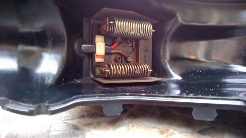
Edit: And to Superhawk's point, when I managed to get my motor spinning, I never really fully rebuilt it, so it probably wasn't spinning as freely as is should. That means more power draw through that resistor at low speed than it was designed for, and 
Posted by: Superhawk996 Jan 21 2021, 01:11 PM
I'm also going to throw another one out there. You didn't mention which fuse was blowing.
Is it pulling power from the proper fuse? Should be fuse #8 - 25A fuse.
Posted by: Superhawk996 Jan 21 2021, 01:22 PM
page 72 post #1439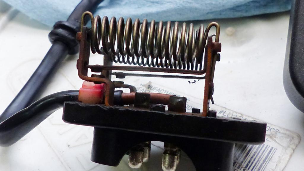
http://www.914world.com/bbs2/index.php?showtopic=307290&st=1420
Here is the detail on the bi-metallic switch BELOW the resistor.
@http://www.914world.com/bbs2/index.php?showuser=20845 problem was only two speeds. Fully acknowlege this is different than your problem but it does detail how the switches are physcially built if you wish to document this thoroughly.
Posted by: BeatNavy Jan 21 2021, 01:50 PM
Ahhh...ok, that filled in at least some of the missing pieces for me. I think I have a better idea how this thing works.
Amazing how complicated it is and how much engineering went in to this little bugger.
Posted by: Superhawk996 Jan 21 2021, 02:06 PM
Here's a few links about the 1/2 split method. This is method of troubleshooting that was taught to me by USAF as the quickest way to troubleshoot electrical equipment. It works. More than happy to elaborate if I can assist. Unfortunately words aren't the best way to describe the process but at the same time I haven't found a great video yet.
I've posted these intermittently in other threads where people are troubleshooting electical systems and some have PM'd me that they found them to be helpful.
https://www.ecmweb.com/maintenance-repair-operations/article/20889049/the-beauty-of-halfsplitting
https://rule11.tech/troubleshooting-half-split/
https://artoftroubleshooting.com/2013/04/25/clear-up-to-here/
Posted by: Superhawk996 Jan 21 2021, 02:07 PM
Amazing how complicated it is and how much engineering went in to this little bugger.
Yup, typical German part!
Posted by: 914_teener Jan 21 2021, 02:21 PM
Glad you guys are getting along.
I did this years ago....twice. Fixed the fan and then the wiper motor gave up the ghost.
Sage advice:
Don't do one without checking the other. The only way to replace the wiper motor is by taking back out the fresh air box and then fan...and then wiper assembly.
Turns out when the OP turned on the fan after it filled up with leaves it burned out the resister and overloaded the wire harness burning it and then shorting to the wiper part of the harness.......
Taking this out twice and tracing down the short and in that process I believe new expletives were invented.
So.....test both while your there.
Posted by: DRPHIL914 Jan 21 2021, 04:34 PM
I'm here to help. Not trying to be a jerk. Apologize if it's coming off that way, I'm an engineer so it comes naturally.
https://www.youtube.com/watch?v=9LaV8lSdOHQ
I have a copy of Prospero's garage laminated schematic. Nice for some things like color codes but sucks for others. Not sure if this is what you have. For the ventillation fan work, it is closer to sucks. The fresh air fan has no component detail on what in there, only a block diagram.
Haynes manual is better IHMO.
@http://www.914world.com/bbs2/index.php?showuser=20845 recently tore into his resistor pack. I can't seem to find the thread at the moment.
There are two wire coil resistors. They control Low and medium. High is wired w/o a resistor to motor per Haynes (white wire) . There is also a bi-metallic thermal cut out switch per the Haynes schematic. The resistors and thermal cutout switches can be verified with DMM.
Unfortunately the Haynes manual isn't clear on how the bimetallic switch is physcially built. Brent's photo's I think had detail. The Haynes manual does show that if the switch is closed, it bypasses the resitor, drives the fan at full speed, and then cools off the wire resistor coil, at which point the bimetallic switch should open again and slow the fan to proper speed.
With respect to the control levers, have you verified the connections and continuity with DMM? "so i could have 3 controllers that all have exactly the same issue OR more likely the issue is at the fan and resistors"
As you state, you could have 3 bad units (not likely) but a quick continuity and/or resistance test with a DMM will verify them and remove any doubt. That is sort of what I was implying by making assumptions. Don't assume that and/or jump to conclusion is at the fan and resistors. Not trying to beat you up on this. It's a very common thing to do that can lead you astray and lot's of people make these sort of inferences when trying to do electical work. Comment above from @http://www.914world.com/bbs2/index.php?showuser=17353 is spot on as we was basically using a half split method either knowingly or by intuition.
The reason I mention DC motor theory is because if you have a motor that isn't free to spin (bad bearings/bushing) it will draw more current than it should and could blow the fuse and/or not even rotate on the lower speed. Likewise, if you have shorted windings in the motor, it could blow fuses. We can verify each of these possibilities in a methodical way. But, let's not get ahead of it yet.
I'm also going to throw another one out there. You didn't mention which fuse was blowing.
Is it pulling power from the proper fuse? Should be fuse #8 - 25A fuse.
page 72 post #1439
http://www.914world.com/bbs2/index.php?showtopic=307290&st=1420
Here is the detail on the bi-metallic switch BELOW the resistor.
@http://www.914world.com/bbs2/index.php?showuser=20845 problem was only two speeds. Fully acknowlege this is different than your problem but it does detail how the switches are physcially built if you wish to document this thoroughly.
 hey its all good, sometimes things come across different in print, but really no offense taken, i can see that engineering mind go to work! my son and my nephew are both engineers, my electrons choose the path of least resistance
  and went with the spinal biomechanical engineering( chiropractor) but really got into the functional biomechanics, always loved learning how everyting works , still learning and digging in on this stuff, but i digress---
- thanks for pointing out the continuity on the controller i will recheck that and compare the other units , i did that a few years ago so will recheck and document it.
- i have a free turning fan, that seems good on this unit , not my spare unit.
- mark and Matt are thinking similar in rebuilding the motor, new ones Bosch are $80 or so, not expensive, but not cheap either.
-i need to check but pretty sure its fuse #8 being blown
if its not that means someone has been messing around. I went thru the whole harness and fuse box when i installed the new box with blade fuses a few years ago. but again i need to not assume but re-verify.
then need to measure the resistance of these 3 circuits on each unit i have.
I wonder if the spring in essence is your resistor but is broken and we know the needed value, should be able to rebuild that i would think right?
first things first.
BTW @http://www.914world.com/bbs2/index.php?showuser=22428 - have read all your build thread since it started, you also have mad fab skills, wish i had the room for doing that kind of work, i had to outsource mine but that ended up being worth at the time, you know time vs money and i dont have a lot of either but still working so thats the way it went.
lots of great infor hear already, will get at measuring and checking on these items and get back here soon.
Phil
Posted by: Superhawk996 Jan 21 2021, 05:01 PM
I wonder if the spring in essence is your resistor but is broken and we know the needed value, should be able to rebuild that i would think right?
@http://www.914world.com/bbs2/index.php?showuser=11106 Thank you for the kind words regarding the rebuild of my
 !
! Just for clarity, it isn't a spring per se. It is basically a wire wound resistor without a housing just suspended in air. The resistive coil is exposed to air flow and is air cooled (like the engine). Pretty neat huh?
If the coils were touching one another, resistance would decrease. If it breaks or goes Poof and opens up, now you have infinite resistance. Either of these scenarios can be checked with a DMM.
In @http://www.914world.com/bbs2/index.php?showuser=17042 's case, if he had a stalled motor (or very slow spinning motor), the low speed resistive element probably got too hot both from too much current draw (from the stalled motor) and lack of cooling from no airflow and then the smoke got out.

Not so simple to repair but not impossible in concept.
The resistive wire is a special alloy designed both for stable resistance per unit of length as well as good thermal properties (doesn't melt easily, stable resistance at various temperatures, etc.).
Here is the Wiki on what it could be.
https://en.wikipedia.org/wiki/Resistance_wire
Nichrome and Magnanin are the most common.
Much easier to find a donor and replace if it turns out to be a resistor.
If I had to McGyver something, I'd start looking at toasters for their resistive elements but that would take some real trial and error to understand if it could even be done.

 More seriously speaking, I'd start looking to other more readily avilable domestic blower motors to see if I could find a similar wire resistive element and would cobble that. Alternatively, you could replace the resistor with say 12 gauge copper wire (zero ohms resistance) and you would esentially have two HIGH speeds. Or I guess, you could just bend the bi-metallic switch contact to be closed all the time. Same result - bypasses the resistor. That was what caused @http://www.914world.com/bbs2/index.php?showuser=20845 's problem.
 With a little math we could roll (i.e. wind) our own.

https://www.amazon.com/Nichrome-80-Gauge-Resistance-Wire/dp/B07CHTY1VV/ref=pd_sbs_147_2/135-3665345-4730920?_encoding=UTF8&pd_rd_i=B07CHTY1VV&pd_rd_r=d34c9d76-a122-4984-a697-809487538d6d&pd_rd_w=TxYfT&pd_rd_wg=STZF0&pf_rd_p=c52600a3-624a-4791-b4c4-3b112e19fbbc&pf_rd_r=JARB7F9N7AHK43ZF4CP8&psc=1&refRID=JARB7F9N7AHK43ZF4CP8
Many thanks to Brent for photographing and documenting that bugger!
Posted by: bbrock Jan 21 2021, 08:31 PM
@http://www.914world.com/bbs2/index.php?showuser=22428 I can't believe you were able to dig that out of my thread. I had forgotten all about it. And yes, my problem was that my blower switch positions went low, high, high. So the blower worked in all positions, but medium speed was missing as it was going straight to high because of that little breaker gizmo.
As for repairing a blown resistor - how important do you suppose it is to use an open coil resistor. Would something like this work as a replacement?
https://www.digikey.com/en/products/detail/te-connectivity-passive-product/HSA502R5J/2366322
It's funny. I have a roll of nichrome wire left over from a failed attempt to build a DIY plexiglass bender many years ago. I remember when I was trouble shooting my blower that I might finally get to use that wire to wind a new resistor. Alas, it was not to be...
Posted by: DRPHIL914 Jan 21 2021, 08:33 PM
I wonder if the spring in essence is your resistor but is broken and we know the needed value, should be able to rebuild that i would think right?
@http://www.914world.com/bbs2/index.php?showuser=11106 Thank you for the kind words regarding the rebuild of my
! Just for clarity, it isn't a spring per se. It is basically a wire wound resistor without a housing just suspended in air. The resistive coil is exposed to air flow and is air cooled (like the engine). Pretty neat huh?
If the coils were touching one another, resistance would decrease. If it breaks or goes Poof and opens up, now you have infinite resistance. Either of these scenarios can be checked with a DMM.
In @http://www.914world.com/bbs2/index.php?showuser=17042 's case, if he had a stalled motor (or very slow spinning motor), the low speed resistive element probably got too hot both from too much current draw (from the stalled motor) and lack of cooling from no airflow and then the smoke got out.
Not so simple to repair but not impossible in concept.
The resistive wire is a special alloy designed both for stable resistance per unit of length as well as good thermal properties (doesn't melt easily, stable resistance at various temperatures, etc.).
Here is the Wiki on what it could be.
https://en.wikipedia.org/wiki/Resistance_wire
Nichrome and Magnanin are the most common.
Much easier to find a donor and replace if it turns out to be a resistor.
If I had to McGyver something, I'd start looking at toasters for their resistive elements but that would take some real trial and error to understand if it could even be done.
More seriously speaking, I'd start looking to other more readily avilable domestic blower motors to see if I could find a similar wire resistive element and would cobble that. Alternatively, you could replace the resistor with say 12 gauge copper wire (zero ohms resistance) and you would esentially have two HIGH speeds. Or I guess, you could just bend the bi-metallic switch contact to be closed all the time. Same result - bypasses the resistor. That was what caused @http://www.914world.com/bbs2/index.php?showuser=20845 's problem. With a little math we could roll (i.e. wind) our own.
https://www.amazon.com/Nichrome-80-Gauge-Resistance-Wire/dp/B07CHTY1VV/ref=pd_sbs_147_2/135-3665345-4730920?_encoding=UTF8&pd_rd_i=B07CHTY1VV&pd_rd_r=d34c9d76-a122-4984-a697-809487538d6d&pd_rd_w=TxYfT&pd_rd_wg=STZF0&pf_rd_p=c52600a3-624a-4791-b4c4-3b112e19fbbc&pf_rd_r=JARB7F9N7AHK43ZF4CP8&psc=1&refRID=JARB7F9N7AHK43ZF4CP8
Many thanks to Brent for photographing and documenting that bugger!
thanks for explanation, it’s fascinating, it is “cool” , and actually amazing how they worked all that out.
all fast would be better than none at all , i need to test mine this weekend so i know what i am looking at.
Posted by: Superhawk996 Jan 22 2021, 06:56 AM
As for repairing a blown resistor - how important do you suppose it is to use an open coil resistor. Would something like this work as a replacement?
https://www.digikey.com/en/products/detail/te-connectivity-passive-product/HSA502R5J/2366322
It would definately work in the sense of functionality.
I think the reason for the open coil resistors is available package space and better cooling.
Looking at the size of the linked resistor, 2"L x 1"W and about the same 1" tall, I don't think it would fit. Could it have leads soldered to the resistor and then soldered to the OEM resistor holder and then mount the thing somewhere? Probably. I would be concerned about potential for the resistor to get hot enough to melt or deform plastic at 50W if JB welded to the housing or something like that. Drill holes for wires to exit the fan housing and mount that style resistor to the body as heat sink?
 Sure, depends on how bad you really need a low or medium speed.
 The key thing I don't know is how much current is the fan pulling at start up (peak in-rush) and what is is steady state operating current. Once we know that, we could properly size the resistors. 50W might be overkill?

Maybe this weekend I'll go over to storage and retrieve my fresh air box. I know mine worked on at least one speed before I tore the car down. Might be a good time to check out my own motor and resistor pack too. I'm hoping to drive this
by Fall so it wouldn't hurt to know my fan is up to snuff. 
Could measure my fan for operating current. But then I'm also supposed to be measureing my 017 CHT sensor vs NOS 012 over on the other thread. So much fun stuff to do so little time.
Posted by: bbrock Jan 22 2021, 08:42 AM
As for repairing a blown resistor - how important do you suppose it is to use an open coil resistor. Would something like this work as a replacement?
https://www.digikey.com/en/products/detail/te-connectivity-passive-product/HSA502R5J/2366322
It would definately work in the sense of functionality.
I think the reason for the open coil resistors is available package space and better cooling.
Looking at the size of the linked resistor, 2"L x 1"W and about the same 1" tall, I don't think it would fit. Could it have leads soldered to the resistor and then soldered to the OEM resistor holder and then mount the thing somewhere? Probably. I would be concerned about potential for the resistor to get hot enough to melt or deform plastic at 50W if JB welded to the housing or something like that. Drill holes for wires to exit the fan housing and mount that style resistor to the body as heat sink?
Sure, depends on how bad you really need a low or medium speed. The key thing I don't know is how much current is the fan pulling at start up (peak in-rush) and what is is steady state operating current. Once we know that, we could properly size the resistors. 50W might be overkill?
Yeah, I was wondering more about the general package style than that particular resistor. The one I linked was just a random selection of twenty-seven 2.5 Ohm chassis mounted resistors that popped up on Digikey that had a nice picture since I didn't know particular power and dimension specs needed offhand. There are many options. For example, here's a 5w resistor only 0.6" long. https://www.digikey.com/en/products/detail/nte-electronics-inc/5WM2D5/11650430
I was surprised not to find a selection of open coil style resistors on Digikey which makes me think either I don't know the correct search term to use, or perhaps that style has been superseded to a modern design for the application. With thousands of resistor options available for almost any given resistance rating, there are surely suitable off the shelf options out there.
I picked the chassis mount to look at because they are mounted in heat sinks for heat dissipation which seems inline with the original design. You could mount those to a small aluminum plate with heat transfer paste for even more efficient heat dissipation.
Posted by: Mikey914 Jan 22 2021, 08:49 AM
I'd look at a standard more "modern" resistor as a replacement. Pretty sure the only reason these are made like this is it was less expensive to build their own than buy them in 1969.
Posted by: DRPHIL914 Jan 22 2021, 08:51 AM
As for repairing a blown resistor - how important do you suppose it is to use an open coil resistor. Would something like this work as a replacement?
https://www.digikey.com/en/products/detail/te-connectivity-passive-product/HSA502R5J/2366322
It would definately work in the sense of functionality.
I think the reason for the open coil resistors is available package space and better cooling.
Looking at the size of the linked resistor, 2"L x 1"W and about the same 1" tall, I don't think it would fit. Could it have leads soldered to the resistor and then soldered to the OEM resistor holder and then mount the thing somewhere? Probably. I would be concerned about potential for the resistor to get hot enough to melt or deform plastic at 50W if JB welded to the housing or something like that. Drill holes for wires to exit the fan housing and mount that style resistor to the body as heat sink?
Sure, depends on how bad you really need a low or medium speed. The key thing I don't know is how much current is the fan pulling at start up (peak in-rush) and what is is steady state operating current. Once we know that, we could properly size the resistors. 50W might be overkill?
Yeah, I was wondering more about the general package style than that particular resistor. The one I linked was just a random selection of twenty-seven 2.5 Ohm chassis mounted resistors that popped up on Digikey that had a nice picture since I didn't know particular power and dimension specs needed offhand. There are many options. For example, here's a 5w resistor only 0.6" long. https://www.digikey.com/en/products/detail/nte-electronics-inc/5WM2D5/11650430
I was surprised not to find a selection of open coil style resistors on Digikey which makes me think either I don't know the correct search term to use, or perhaps that style has been superseded to a modern design for the application. With thousands of resistor options available for almost any given resistance rating, there are surely suitable off the shelf options out there.
I picked the chassis mount to look at because they are mounted in heat sinks for heat dissipation which seems inline with the original design. You could mount those to a small aluminum plate with heat transfer paste for even more efficient heat dissipation.
Posted by: Superhawk996 Jan 22 2021, 09:16 AM
Not trying to be a kill joy on the DigiKey resistors but I suspect that in the desire to find a nice "modern" looking resistor you've over looking the physics and the cooling requirements.
These packaged high watt resistors require a heat sink to last. Once that aluminum case gets hot and has no heat sink to pull the heat away, it will get too hot and burn open in short order. That's why I referenced the idea of wires exiting the HVAC case and having to mount it on the sheetmetal body as a heat sink.
Likewise, that style of heavy resistor if left unsupported within the blower case is going to fatigue the OEM resistor standoffs that were not designed to support that kind of resistor weight when dynamic road loads are imposed on it.
A thick gauge wire wound resistor in open air is going to be able to handle more current and heat rejection than a nice neat ceramic or aluminum heat sink package that looks aerospace cool.
I look at it as the industry having converged upon the best, most cost effective solution and it's not one of those DigiKey style resistors.
Poke around on internet and you'll quickly find the converged solutions are resident in the blower case, they are air cooled. Typically open wire coil, large ceramic, or Solid State with big honking cooling fins in the air stream. You'll notice in a couple that the bi-metallic thermal cut out switch has been replaced by a more modern component though!
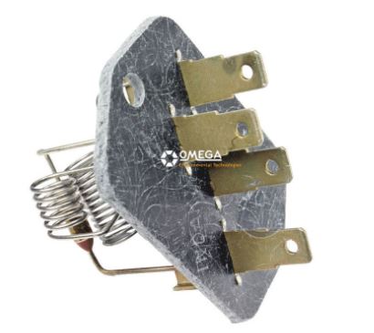
https://www.finditparts.com/products/5947002/omega-environmental-technologies-mt1363?srcid=CHL01SCL010-Npla-Dmdt-Gusa-Svbr-Mmuu-K5947002-L346&gclid=EAIaIQobChMIs4amluiv7gIVzsDACh1WKgQzEAQYASABEgJSDfD_BwE
https://shop.advanceautoparts.com/p/bwd-hvac-blower-motor-resistor-ru1181/10014965-p?product_channel=local&store=8718&adtype=pla&product_channel=local&store_code=8718&gclid=EAIaIQobChMI-YKktumv7gIVivDACh1ryQdlEAQYAyABEgK1E_D_BwE&gclsrc=aw.ds
https://www.walmart.com/ip/Blower-Motor-Resistor-AC-Heater-For-Ford-Fusion-2-5L-2007-2012-8E5Z19E624A/983225433?wmlspartner=wlpa&selectedSellerId=101037099&&adid=22222222227391069391&wl0=&wl1=g&wl2=c&wl3=480264578783&wl4=pla-1020984168184&wl5=9016979&wl6=&wl7=&wl8=&wl9=pla&wl10=280608662&wl11=online&wl12=983225433&veh=sem&gclid=EAIaIQobChMIq77n2emv7gIVqOHACh0XtgKJEAQYBCABEgI7CfD_BwE
Posted by: bbrock Jan 22 2021, 09:03 PM
Not trying to be a kill joy on the DigiKey resistors but I suspect that in the desire to find a nice "modern" looking resistor you've over looking the physics and the cooling requirements.
Wasn't trying to find a modern looking resistor. I was just trying to find any suitable replacement. I was actually searching for open coil resistors like what are in the blower and shocked not to be able to find them among the 500,000+ resistors in their catalog (or anywhere). I'm not saying they are not there, only that I couldn't find them.
I am a bit offended though.
 Even I'm not dumb enough to try to hang one of those chassis mount resistors from the OEM standoffs. I envisioned mounting to an aluminum plate, glued to the base of the resistor pack, and connected with flexible leads. Irrelevant if they are not suitable.
I'm still puzzled why open wire coil resistors are not easier to find. Even resistor wire is kind of hard to find. All the stuff I've seen is annealed and too soft to make those spring like coils.
Posted by: bdstone914 Jan 23 2021, 12:18 AM
Not trying to be a kill joy on the DigiKey resistors but I suspect that in the desire to find a nice "modern" looking resistor you've over looking the physics and the cooling requirements.
Wasn't trying to find a modern looking resistor. I was just trying to find any suitable replacement. I was actually searching for open coil resistors like what are in the blower and shocked not to be able to find them among the 500,000+ resistors in their catalog (or anywhere). I'm not saying they are not there, only that I couldn't find them.
I am a bit offended though. Even I'm not dumb enough to try to hang one of those chassis mount resistors from the OEM standoffs. I envisioned mounting to an aluminum plate, glued to the base of the resistor pack, and connected with flexible leads. Irrelevant if they are not suitable.
I'm still puzzled why open wire coil resistors are not easier to find. Even resistor wire is kind of hard to find. All the stuff I've seen is annealed and too soft to make those spring like coils.
@http://www.914world.com/bbs2/index.php?showuser=20845
I can supply you a good used resistor assembly.
Posted by: bbrock Jan 23 2021, 02:04 AM
Not trying to be a kill joy on the DigiKey resistors but I suspect that in the desire to find a nice "modern" looking resistor you've over looking the physics and the cooling requirements.
Wasn't trying to find a modern looking resistor. I was just trying to find any suitable replacement. I was actually searching for open coil resistors like what are in the blower and shocked not to be able to find them among the 500,000+ resistors in their catalog (or anywhere). I'm not saying they are not there, only that I couldn't find them.
I am a bit offended though. Even I'm not dumb enough to try to hang one of those chassis mount resistors from the OEM standoffs. I envisioned mounting to an aluminum plate, glued to the base of the resistor pack, and connected with flexible leads. Irrelevant if they are not suitable.
I'm still puzzled why open wire coil resistors are not easier to find. Even resistor wire is kind of hard to find. All the stuff I've seen is annealed and too soft to make those spring like coils.
@http://www.914world.com/bbs2/index.php?showuser=20845
I can supply you a good used resistor assembly.
Thanks Bruce, Mine's actually in excellent condition and working well. I was just curious what replacement options for resistors were. It shouldn't be as hard as it seems to be. I get a perverse pleasure out of such challenges.
Posted by: Superhawk996 Jan 24 2021, 12:18 PM
I am a bit offended though.
@http://www.914world.com/bbs2/index.php?showuser=20845 Here to serve!
 I'm sure with a little time, you'd master the process to harden and then temper the annealed wire properly to roll your own!
 Posted by: Superhawk996 Jan 24 2021, 12:35 PM
Well it turns out I will be posting a WTB.
My blower works on all three speeds but the plastic housing is pretty rough. Cracked, missing clips that hold the 1/2's together, and one set of clip mounts is broken off completely. Motor vibrates like bearings/bushings are worn and/or needs to be rebalanced.
Not sure who messed with my car somewhere in it's life but it was certainly owned at some point by the type of person that you could lock in an empty room, alone with two ball bearings. Come back 1 hour later and they would have broken one and lost the other.
OK, here are my measurements. Hope this helps you troubleshoot yours. @http://www.914world.com/bbs2/index.php?showuser=11106 
All were measured at 70F so amperage could be sustantially higher on cold morning with a sluggish motor that is drawing current closer to stall current. I'm surprised at the current this little bugger of a motor can draw! No wonder it's on a 25A fuse! 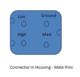
Posted by: DRPHIL914 Jan 24 2021, 07:03 PM
Well it turns out I will be posting a WTB.
My blower works on all three speeds but the plastic housing is pretty rough. Cracked, missing clips that hold the 1/2's together, and one set of clip mounts is broken off completely. Motor vibrates like bearings/bushings are worn and/or needs to be rebalanced.
Not sure who messed with my car somewhere in it's life but it was certainly owned at some point by the type of person that you could lock in an empty room, alone with two ball bearings. Come back 1 hour later and they would have broken one and lost the other.
OK, here are my measurements. Hope this helps you troubleshoot yours. @http://www.914world.com/bbs2/index.php?showuser=11106
All were measured at 70F so amperage could be sustantially higher on cold morning with a sluggish motor that is drawing current closer to stall current. I'm surprised at the current this little bugger of a motor can draw! No wonder it's on a 25A fuse!
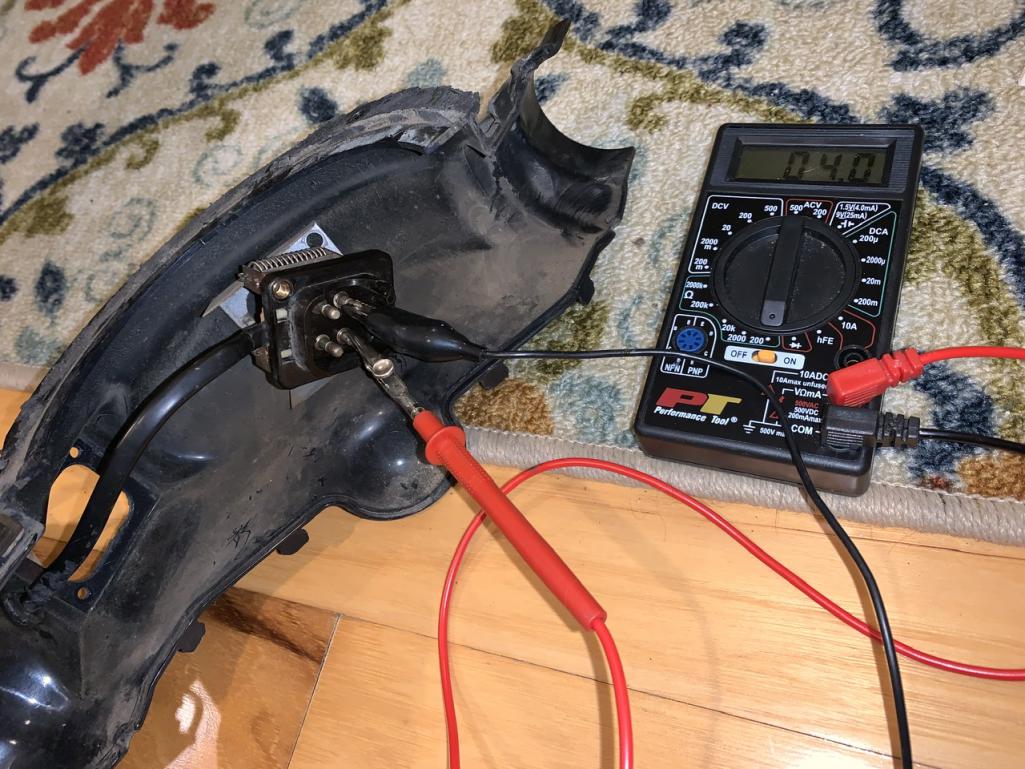
thanks foe the info, just pulled my original fan and housing and just sitting here checking resistance of each circuit i get less than 1 ohm on each one , in fact all 3 test at about .8.
so i guess new resistor pack is necessary, but i will be pulling this apart, the fan does not turn easily, new bearing ans seals and maybe motor , will see if i can clean it all up once it’s out , doesn’t look too good, it’s been apart before someone put it back together and used silicone sealant between the upper and lower parts ugh.
Attached thumbnail(s)
Posted by: Superhawk996 Jan 25 2021, 06:42 AM
@http://www.914world.com/bbs2/index.php?showuser=11106
" . . . so i guess new resistor pack is necessary". Not mentioning to beat you up but to reinforce how it important RULE #1 is in electrical trouble shooting. We've all done this. It was trained out of me and then has been proven by over 30 years of troubleshooting both electrical and mechanical systems.
Sounds to me first thing to do is to pull the resistor pack. Verify -- don't assume.
Resistors usually fail open. It is very rare for a resistor to fail as a short.
If you have 0.8 ohms on all three, it sounds to me like the bimetallic switches are continiously closed. Could be similar to Brent's situation. In his case, he had one of them closed all the time and tweaked it with a pair of pliers to be normally open as it should be. Testing with DMM can verify this. 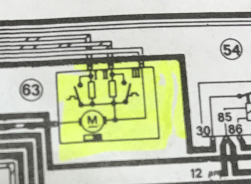
However, if this is the case, you really should have 3 high speeds already.
You can bench test the fan with 12v battery and some wire jumpers. Did you try that by chance?
Lack of airflow could have overheated the resistors and caused the bi-metallic switches to become deformed and to have become normally closed instead of normally open per the schematic. That is a theory and an assumption. A bench test of the reistor pack and of the fan itself will verify or disprove that hypothesis.
Posted by: DRPHIL914 Jan 25 2021, 07:10 AM
@http://www.914world.com/bbs2/index.php?showuser=11106
" . . . so i guess new resistor pack is necessary". Not mentioning to beat you up but to reinforce how it important RULE #1 is in electrical trouble shooting. We've all done this. It was trained out of me and then has been proven by over 30 years of troubleshooting both electrical and mechanical systems.
Sounds to me first thing to do is to pull the resistor pack. Verify -- don't assume.
Resistors usually fail open. It is very rare for a resistor to fail as a short.
If you have 0.8 ohms on all three, it sounds to me like the bimetallic switches are continiously closed. Could be similar to Brent's situation. In his case, he had one of them closed all the time and tweaked it with a pair of pliers to be normally open as it should be. Testing with DMM can verify this.
However, if this is the case, you really should have 3 high speeds already.
You can bench test the fan with 12v battery and some wire jumpers. Did you try that by chance?
Lack of airflow could have overheated the resistors and caused the bi-metallic switches to become deformed and to have become normally closed. That is a theory and an assumption. A bench test will verify that hypothesis.
completely agree, but just didnt have time last night,
plan for tonight is to bench test wit the batter charger, put 12 volts in there and see what we get, then pull it out so i can inspect the resistor pack up close, see if that bi-metallic strip is stuck together. so will verify . the resistance values seemed strange to me to, was trying to figure out how it would fail that way. fan does not spin freely so so doubt i have to get this one pulled apart and cleaned up and see if lub will help. Ive heard that the motors really dont fail or burn out often, dont know if that is true,
But talked to Bruce Stone over the weekend and he suggested doing the same bench test, inspection, etc. and i have all new seals and hardware coming from Mark too.
will report back tonight.
Posted by: Superhawk996 Jan 25 2021, 07:24 AM
. . . plan for tonight is to bench test wit the battery charger . . .
Would be better to use a 12v battery as the source if you can. Battery chargers vary widely and some are really only 1/2 wave rectified and don't have a full 12 volt steady output. It can cause the fan motor to run slower than it would with a battery.
Likewise, it may be current limited. I tested stall current with a battery and it pulled 15A or so. If the battery charger can only deliver 10A, you may not get full speed and/or have sufficient amperage to turn motor if it is binding a little.
Here is what I mean by 1/2 wave output. Can go to site if you want more info.

Posted by: Superhawk996 Jan 25 2021, 07:38 AM
@http://www.914world.com/bbs2/index.php?showuser=11106
I'm going to pick one more snippet from your quote. Not trying to beat up on you personally, but, it speaks to Rule #2. If I'm making you mad by picking out snippets, I'll stop, just let me know. However, it illustrates how I got to the rules we started with.
" . . . the resistance values seemed strange to me to, was trying to figure out how it would fail that way."
This is why a good schematic is a must have. Depending on the complexity of the system, It can be hard, if not impossible troubleshoot effectively without a schematic.
Good schematic from Haynes. B&W is a bit more work to read for color codes but all info is available. The schematic explains the switches, their normal position, and their operation. 
Nice for color codes, but, a block diagram is useless for this type of troubleshooting. Explains nothing other than the colors of the wire. 
Posted by: DRPHIL914 Jan 25 2021, 08:09 AM
@http://www.914world.com/bbs2/index.php?showuser=11106
I'm going to pick one more snippet from your quote. Not trying to beat up on you personally, but, it speaks to Rule #2. If I'm making you mad by picking out snippets, I'll stop, just let me know. However, it illustrates how I got to the rules we started with.
" . . . the resistance values seemed strange to me to, was trying to figure out how it would fail that way."
This is why a good schematic is a must have. Depending on the complexity of the system, It can be hard, if not impossible troubleshoot effectively without a schematic.
Good schematic from Haynes. B&W is a bit more work to read for color codes but all info is available. The schematic explains the switches, their normal position, and their operation.
Nice for color codes, but, a block diagram is useless for this type of troubleshooting. Explains nothing other than the colors of the wire.
no, please i appreciate the info, and being educated!
help me understand the basics like being able to read the schematics will help me trouble shoot other issues in the future,
so the M is the motor correct, and #3 high does not go thru either of the resistors, just the bimetalic plate? if the plate were not conducting current you would not get the fan to run on that setting and resistance with be infinity(short?)
Posted by: Superhawk996 Jan 25 2021, 08:25 AM
@http://www.914world.com/bbs2/index.php?showuser=11106
so the M is the motor correct -- Yes, Correct
and #3 high does not go thru either of the resistors -- Correct
. . if the plate were not conducting current you would not get the fan to run on that setting -- can't really answer that question without a physical inspection of the assembly. I tried to look at BeatNavy's photos and I still can't tell for sure. However, I can see from the photo the plate is basically a thick, solid copper trace. The chance of that opening up is slim to none. The amount of current it would take to melt that open would have melted the external wiring 1st. I think I might be misunderstanding the question. Let's call the switches; bi-metallics switches. What I'm calling the plate is the structure that the reistors and the bi-metallic switches are attached to. So when a bi-metallic switch is normally open you would read the resistance of the Motor + the resistor. When the bi-metallic switch is closed (should only be when the resistor is over heating), the bi-metallic switch deforms to the closed position, and bypasses the resistor with a short (zero ohm) connection, and the motor would run in high speed (just like position #3), the fan should pull more air across the resistor, cool it down, and then the bi-metallic switch should return to the normally open position and the fan would return to its regulated speed. If the bi-metallic switch were permanently deformed to be normaly closed (even when cool) then you would read the motor resistance only just like you would in position #3.
and resistance with be infinity(short?) -- A short = 0 ohms, open circuit = infinity. Since you are reading 0.8 ohm on all three speeds, we know the plate is not open and, that we have conductivity between all three potential current paths though the motor
Adding on: Around each resistor, you see a switch that operates as a square wave. Either OFF or ON. When that switch closes, you have a short around the wire wound resistor. Therefore, you would only read the motor winding resistance when measuring though the switch if this switch were closed. These are the bi-metallic switches that are located blow the resitors in Brent's photo.
Note: DMM's can have 0.1- 0.3 ohm of resistance just in the leads (especially if using add-on's like alligator clips. My cheap DMM reads 0.2 ohms with a dead short and alligator clips attached. So moral of the story is your ohm readings may differ slightly and/or a dead short may still show as 0.2 ohms or so.
Posted by: DRPHIL914 Jan 25 2021, 06:14 PM
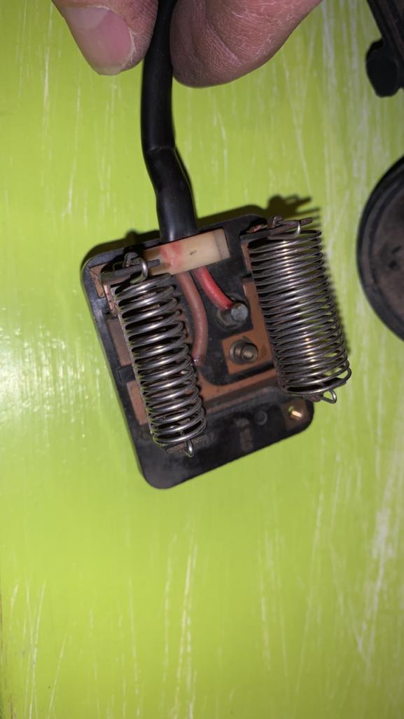
took the sucker apart and retested the resistor pack without being hooked up to motor,
values are:
Low- 1.5
Medium- 3.4
high- 1-1.5
@http://www.914world.com/bbs2/index.php?showuser=22428
pictures of it show both bimetallic strips in good condition and open
Attached thumbnail(s)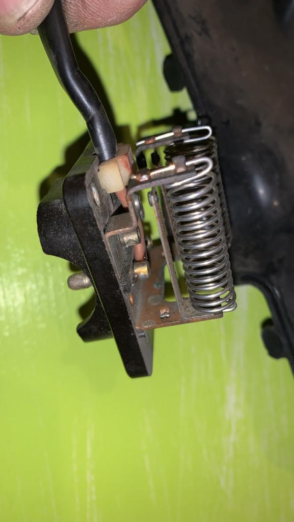
Posted by: bbrock Jan 25 2021, 07:19 PM
took the sucker apart and retested the resistor pack without being hooked up to motor,
values are:
Low- 1.5
Medium- 3.4
high- 1-1.5
@http://www.914world.com/bbs2/index.php?showuser=22428
pictures of it show both bimetallic strips in good condition and open
Where are placing the probes to measure resistance and do you see any resistance specs on the resistor pack? My is stamped 2.5 ohms for the low speed resistor and 0.75 for medium speed. Measuring resistance with probes on each end of the resistor, I got 2.5 ohms on the nose for the low side, and 1.1 ohms on the medium side. The medium sides was higher than what was stamped but works okay so I think those stamps are ballpark.
Posted by: Superhawk996 Jan 26 2021, 06:11 AM
@http://www.914world.com/bbs2/index.php?showuser=11106
Agree with @http://www.914world.com/bbs2/index.php?showuser=20845 's comments, need to know exactly where you measured from both initially and on this latest round of measurements.
Before we go there, let's acknowlege something changed that doesn't make sense. If you were measuring 0.8 ohms on all three settings before and now you're measuring higher resistances with the resistor pack disconnected from the motor, something is wrong.
The motor + a resistance value should always be higher than just measuring the resistors alone. Since resistances went up since 1st round, something isn't correct.
Another key item that is basic to electronics work is that in order to measure resistance, the component (or system) under measurement must be disconnected from the rest of the system. For example, we cannot measure the resistance of the fresh air motor + resistor with the motor assembly plugged into the rest of the vehicle wiring and HVAC slider controls. I assumed the fresh air box was completely disconnected from the vehicle when the 0.8 ohms was reported but maybe I made a bad assumption despite my own Rule #1. See, we all do it despite our best attempt.
This is probably a good point to talk about Rule #4, half splitting. The goal is to divide things in 1/2 to isolate which side the problem is on. By disconnecting the fan motor & resistor assembly, we dive the system into two. The vehicle side (vehicle wiring, HVAC control, connectors) and the fresh air box assembly (motor, resistor, and the short bit of wire inside).
I had assumed we were working on just the 1/2 system of the fresh air box completely disconnected from the vehicle and wiring. Is that valid?
To continue the 1/2 split conversation, we can now split the fresh air box system in 1/2 again. We can divide system to the motor only disconnected from the resistor pack, and the resistor+stub of wire that connects to the motor.
So on the resitor pack; disconnected from the motor, (1/4 of the sytem as we currently have it divided) I'd like you to measure the resistors only (measure one resistor post to the other resistor post) with nothing else connected to it. That will give us the value of the two resistors alone.
By inspection we can see the bi-metallic switches are open. We might measure that later just to be sure but for now let's just get the resistor values and see if they come close to Brent's or BeatNavy's measurements and/or markings on the housing.
The other thing we can do is to measure the other 1/4 of the system (the motor only). With the resistor pack disconnected from the motor, what does the motor resistance measure? Does it change drasticallywhen you rotate the position of the fan impeller from one position to another?
We can also physically test just the fan -- it can be hooked to a 12 volt battery to see if it spins.
Let's try this and see where we end up as we try to resolve why the system changed. Worst case, we will put the motor + resistor 1/2 of the system back together and can see if we can duplicate your original 0.8 ohm measurements. Not likely to have to do this once we go through the steps above.
Posted by: DRPHIL914 Jan 26 2021, 10:27 AM
@http://www.914world.com/bbs2/index.php?showuser=11106
Agree with @http://www.914world.com/bbs2/index.php?showuser=20845 's comments, need to know exactly where you measured from both initially and on this latest round of measurements.
Before we go there, let's acknowlege something changed that doesn't make sense. If you were measuring 0.8 ohms on all three settings before and now you're measuring higher resistances with the resistor pack disconnected from the motor, something is wrong.
The motor + a resistance value should always be higher than just measuring the resistors alone. Since resistances went up since 1st round, something isn't correct.
Another key item that is basic to electronics work is that in order to measure resistance, the component (or system) under measurement must be disconnected from the rest of the system. For example, we cannot measure the resistance of the fresh air motor + resistor with the motor assembly plugged into the rest of the vehicle wiring and HVAC slider controls. I assumed the fresh air box was completely disconnected from the vehicle when the 0.8 ohms was reported but maybe I made a bad assumption despite my own Rule #1.
See, we all do it despite our best attempt. This is probably a good point to talk about Rule #4, half splitting. The goal is to divide things in 1/2 to isolate which side the problem is on. By disconnecting the fan motor & resistor assembly, we dive the system into two. The vehicle side (vehicle wiring, HVAC control, connectors) and the fresh air box assembly (motor, resistor, and the short bit of wire inside).
I had assumed we were working on just the 1/2 system of the fresh air box completely disconnected from the vehicle and wiring. Is that valid?
To continue the 1/2 split conversation, we can now split the fresh air box system in 1/2 again. We can divide system to the motor only disconnected from the resistor pack, and the resistor+stub of wire that connects to the motor.
So on the resitor pack; disconnected from the motor, (1/4 of the sytem as we currently have it divided) I'd like you to measure the resistors only (measure one resistor post to the other resistor post) with nothing else connected to it. That will give us the value of the two resistors alone.
By inspection we can see the bi-metallic switches are open. We might measure that later just to be sure but for now let's just get the resistor values and see if they come close to Brent's or BeatNavy's measurements and/or markings on the housing.
The other thing we can do is to measure the other 1/4 of the system (the motor only). With the resistor pack disconnected from the motor, what does the motor resistance measure? Does it change drasticallywhen you rotate the position of the fan impeller from one position to another?
We can also physically test just the fan -- it can be hooked to a 12 volt battery to see if it spins.
Let's try this and see where we end up as we try to resolve why the system changed. Worst case, we will put the motor + resistor 1/2 of the system back together and can see if we can duplicate your original 0.8 ohm measurements. Not likely to have to do this once we go through the steps above.
i can do more of this tonight. to answer a few questions, when i tested it and got the.8, we had the 1/2 split, i was testing the fan assembly out of the car, but motor in
and i dont know what was wrong with reading but fan was hooked up , my new readings were with the fan split so just testing the resistors from neutral to each lead with aligator clips and did it with the probe on end or side of the male connector and reuslt was exactly the same, the 1.5, 3.5 and 1.0 for high which seems strange .
i will try and test the fan motor tonight and give it power, see how it turns,
Phil
now we can test the sliders by its self, i tried but was not doing something correctly as i didnt get a proper value.
Posted by: Superhawk996 Jan 26 2021, 12:19 PM
. . . I will try and test the fan motor tonight and give it power, see how it turns,
Phil
now we can test the sliders by its self, i tried but was not doing something correctly as i didnt get a proper value.
@http://www.914world.com/bbs2/index.php?showuser=11106
Before we go to the sliders we still need to figure out whats going on in this 1/2 of the system. Let's not assume that if resistors are OK that the problem isn't on this 1/2. Test & verify in a methodical manner before we rule anything out.
Plan:
1) Let's verify resistors:
a. Test each reistor from from post to post and report those values - should be close to the other guys. Note: be sure your test leads are scratching the surface of the posts a bit to get down to clean copper. Oxidation on copper traces will add some resistance.
b. You'll notice that two of the reisistors are tied together. This is the end of the resistor bank that should lead to the motor and should also be connected to the high speed pin per the schematic.
2) Bench test just the motor
3) Let's assume the resistors measure OK. I'd like to put the motor / resistor back together and re-verify resistances. We need to understand why your low and high resistances were the same. I suspect we have the ground reference point wrong either per your measurement technique or how I labeled the connector. I'll try to re-verify my connector and reverify my measurements on my blower to make sure I drew that right.
4) Bench test the motor + resistor assembly. Verify all three speeds work on the bench.
Let's do that before we move to other potential causes in wiring and/or in control levers.
Posted by: DRPHIL914 Jan 27 2021, 11:29 AM
@http://www.914world.com/bbs2/index.php?showuser=22428
i went back and retested the resistors like you suggested, post to post same results, then i hooked up the motor to the leads, rechecked the low and medium we’re about same , the high on the other hand was like 121?? here are pictures-
the high post is the one with red wire(+) that goes to motor, from motor that brown ground wire (-) goes back to the resistor pack so the black lead is on that post for each test.
i did not bench test the motor with 12v but i can tell you it’s difficult to turn by hand it’s not freely spinning, housing is apart and the fan seal broke and no one makes them yet- hey Mark! @http://www.914world.com/bbs2/index.php?showuser=3348 
also pictures of the fan motor assembly, it’s now out. it’s different than the new ones, they don’t have the metal housing like this. anyone order one of the new ones from URO or Porsche?
how do you take the motor out of the white fan part? i took the black top part off by taking the 3 spring clips off that hold those 2 parts together - the black part holds the big seal .
Attached thumbnail(s)


Attached image(s)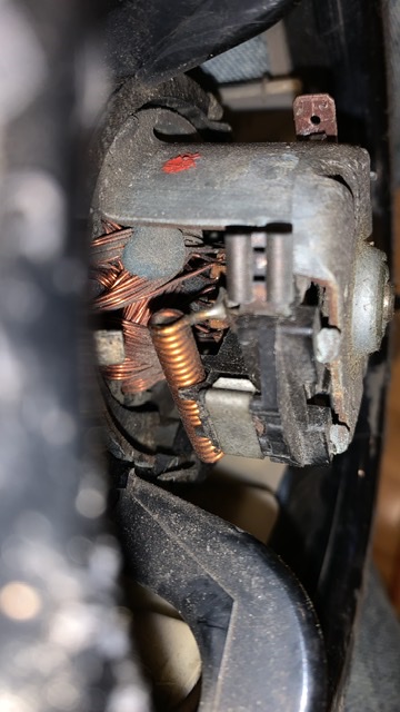
Posted by: Superhawk996 Jan 27 2021, 12:37 PM
@http://www.914world.com/bbs2/index.php?showuser=11106
Great job gutting that beast! Especially so if you did it without breaking any of the clip plastic stanchions.
We've got a mystery. Love it.
So the good news is that youre saying the resistors roughtly make sense measued post to post.
Low = 1.5 ohm initial to 2.1 ohm 2nd time. Perfect!
Medium = 3.4 ohm initial to 4.0 ohm 2nd time Perfect!
High = something is jacked up.
I'm a little leary of your meter given that very 1st round of measurements measured 0.8 ohm on everything and now things are measuring much better for the medium and low resistors but way, way off for High. Something very odd going on here. We're going to stay here for a bit until we can 1) verify your meter is OK, or 2) Get repeatability to the readings, or 3) find some other root cause that explains all this weirdness.
Ideas to move forward:
1) Are you abslolutely sure the meter leads aren't having connectivity issues of their own? I've had leads similar to yours, where you can unsrew the plastic lead housing from the metal tip, and the lead wire is soldered to the test tip. I've had bad solder joints on these type of leads before. Beware of these type test leads. 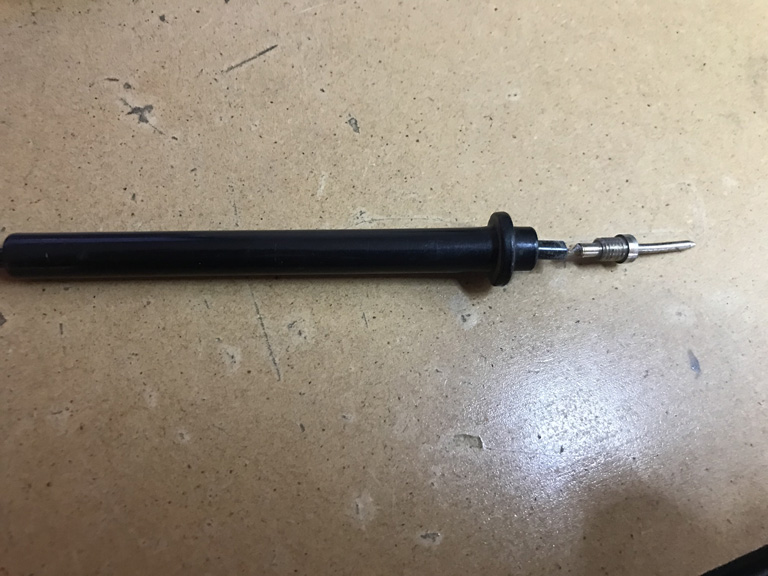
a) I'm going to assume this isn't likely and that you performed the low and medium measurements after doing high and getting 121 ohm on high and by measuring 4 ohm type connections on M & L immediatly following the 121 ohm we can be partially convinced the problem isn't in the test lead.
2) When you did measure the high postion is there any chance the aligator clip wasn't making good connection on the high post? If you tried wiggling the aligatior clips to scratch the post and/or pressed the clip together while wiggling to get though any post corrostion and you measured 121 ohms multiple times, we'll assume it wasn't a fluke of the connection of the test lead.
3) If High is indeed repeatable at 121 ohms:
a) let's look very closely at the copper trace connections on the resistor block for small crack, signs, of corrosion, or bad connectivity.
b) Are the connector pin posts soldered? I think I recall they are. Could be a cold solder joint between the high post and the wire and/or copper trace. Sometimes you can see a cold solder joint with a 5-10x loupe. Other times I've just had to re-heat the solder and it improves.
c) any chance the motor rotated ever so slightly between measuring L & M to when you measured High? I'm wondering if the motor brushes are worn and all of sudden had high resistance to the motor commutator when you happened to measure high?
I'll tear my blower down tonight and to verify how the resistor pack is built and see if I can get some good photos to point you toward the motor brushes and the bearings to see if we can get your motor freed up in order to bench test it.
Posted by: DRPHIL914 Jan 27 2021, 01:17 PM
@http://www.914world.com/bbs2/index.php?showuser=11106
Great job gutting that beast! Especially so if you did it without breaking any of the clip plastic stanchions.
We've got a mystery. Love it.
So the good news is that youre saying the resistors roughtly make sense measued post to post.
Low = 1.5 ohm initial to 2.1 ohm 2nd time. Perfect!
Medium = 3.4 ohm initial to 4.0 ohm 2nd time Perfect!
High = something is jacked up.
I'm a little leary of your meter given that very 1st round of measurements measured 0.8 ohm on everything and now things are measuring much better for the medium and low resistors but way, way off for High. Something very odd going on here. We're going to stay here for a bit until we can 1) verify your meter is OK, or 2) Get repeatability to the readings, or 3) find some other root cause that explains all this weirdness.
Ideas to move forward:
1) Are you abslolutely sure the meter leads aren't having connectivity issues of their own? I've had leads similar to yours, where you can unsrew the plastic lead housing from the metal tip, and the lead wire is soldered to the test tip. I've had bad solder joints on these type of leads before. Beware of these type test leads.
a) I'm going to assume this isn't likely and that you performed the low and medium measurements after doing high and getting 121 ohm on high and by measuring 4 ohm type connections on M & L immediatly following the 121 ohm we can be partially convinced the problem isn't in the test lead.
2) When you did measure the high postion is there any chance the aligator clip wasn't making good connection on the high post? If you tried wiggling the aligatior clips to scratch the post and/or pressed the clip together while wiggling to get though any post corrostion and you measured 121 ohms multiple times, we'll assume it wasn't a fluke of the connection of the test lead.
3) If High is indeed repeatable at 121 ohms:
a) let's look very closely at the copper trace connections on the resistor block for small crack, signs, of corrosion, or bad connectivity.
b) Are the connector pin posts soldered? I think I recall they are. Could be a cold solder joint between the high post and the wire and/or copper trace. Sometimes you can see a cold solder joint with a 5-10x loupe. Other times I've just had to re-heat the solder and it improves.
c) any chance the motor rotated ever so slightly between measuring L & M to when you measured High? I'm wondering if the motor brushes are worn and all of sudden had high resistance to the commutator when you happened to measure high?
I'll tear my blower down tonight and to verify how the resistor pack is built and see if I can get some good photos to point you toward the motor brushes and the bearings to see if we can get your motor freed up in order to bench test it.
i did rotate the motor while hooked up and on the low and medium they change of course during turning it and return to the static number, the high same way, it returns to the 120 reading like 3x , on off back, test side and end of then. yes they are soldered , will try and clean contacts a bit and recheck the positive/high lead, have to find my solder gun, but they look and feel solid.
Posted by: DRPHIL914 Jan 27 2021, 01:24 PM
i am going to get new leads, yes mine pulled apart like that and i re- attached it , soldered it back but the other one not so good, so next step get that motor freed up, try and source a new seal/replacement, bench test the motor,
but i do have a fan motor assembly coming from Al Merideth he had a good one, so if this doesnt get fixed i had a spare on hand soon, but goal here is to get this tested figured out and fixed and rebuilt and working, so onward ho!!!!
Posted by: 914werke Jan 27 2021, 01:27 PM
Ive sold a couple of them https://914werke.com/shop/ols/products/heater-fan/v/FSH-AIR-FAN-RPR never had any feedback (pro or con) from those sales
Posted by: Superhawk996 Jan 27 2021, 01:38 PM
@http://www.914world.com/bbs2/index.php?showuser=3348
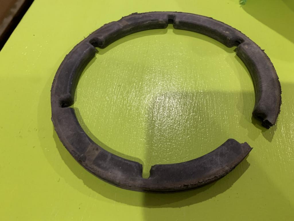
I'll put in a 2nd vote for wish list of this gasket between motor and the blower housing. I can see mine is dry rotted too. Would be lovely to have a complete foam package available, blower motor to blower housing, blower vane seals, blower to upper housing, upper housing to body.
When I tear mine down to resolve the motor vibration and to clean I'm sure I'll destroy the foam too. Obviously cheapo Home Depot suff could be used in a pinch but it would be sweet to get a whole kit as one stop shopping.
I've got a second unit on it's way to me because my upper housing is cracked and has cracked drain tube so I'm assuming that unit will likely need new foam too.
Posted by: bbrock Jan 27 2021, 02:34 PM
Hey Phil, if those pics show where you are measuring the resistance, I still don't think you are getting an accurate read on just the resistors. You should clip the probes to the ends of the resistors themselves rather than the connector pins. I'd have to look at the schematic again but I think it might still be measuring through the motor since it is still connected to the harness.
Posted by: Mikey914 Jan 27 2021, 06:16 PM
Actually I've been working on a more complete kit for this type of We have made the seal you speak of. That and a bunch more parts.
@http://www.914world.com/bbs2/index.php?showuser=11106 has a care package I sent him you will see shortly. I will be opening up a GB as soon as he completes the build.
Mark
Attached thumbnail(s)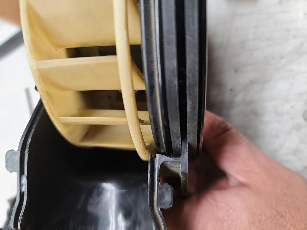
Posted by: Superhawk996 Jan 27 2021, 08:58 PM
how do you take the motor out of the white fan part?
@http://www.914world.com/bbs2/index.php?showuser=11106
After having just totally screwed up my blower motor trying to remove the impeller all I can say is DON'T DO IT.
I was willing to risk mine since the fan was vibrating so badly and I could feel significant side play in the shaft. Likewise the impeller already had several cracked vanes before I started this that were deflecting and also causing vibration. I had little to loose.
What a fiasco. It's pretty rare that I get into disassembling something and then realizing that I've just Fuched it up beyond all hope. But this motor assembly is it.
The bottom line is the impeller is held on by a spring clip that clamps the impeller to the shaft. Mine would not release even after removing the clip. Gentle persuasion didn't work. A bit of gentle warming to sofen the platic relative to the steel shat. Nope. Then came the hammer
 for a gentle tap and then all hell broke loose.
 I'm not sure I even want to go into the rest of the story. Needless to say, this one ain't ever gonna be the same again. RIP.

On this next unit I have coming I'll hope it is starting from a better place than this one was which was clearly heavily molested before I got to it. If the impeller is filthy and broken like mine was on this one, I'd just clean carefully with alcohol and then just carefully super glue the cracked vanes and that is all.
I also noticed that the impeller was balanced as a motor/impeller assembly so by removing the impeller, it would likely only have compounded my vibration problems even discounting for the motor shaft side play. I marked mine in anticipation of this but the reality is that it was going to be a gamble if I could even assemble it with the fan clocked correctly had all the other bad
not happened.
Posted by: DRPHIL914 Jan 27 2021, 11:40 PM
how do you take the motor out of the white fan part?
@http://www.914world.com/bbs2/index.php?showuser=11106
After having just totally screwed up my blower motor trying to remove the impeller all I can say is DON'T DO IT.
I was willing to risk mine since the fan was vibrating so badly and I could feel significant side play in the shaft. Likewise the impeller already had several cracked vanes before I started this that were deflecting and also causing vibration. I had little to loose.
What a fiasco. It's pretty rare that I get into disassembling something and then realizing that I've just Fuched it up beyond all hope. But this motor assembly is it.
The bottom line is the impeller is held on by a spring clip that clamps the impeller to the shaft. Mine would not release even after removing the clip. Gentle persuasion didn't work. A bit of gentle warming to sofen the platic relative to the steel shat. Nope. Then came the hammer
for a gentle tap and then all hell broke loose. I'm not sure I even want to go into the rest of the story. Needless to say, this one ain't ever gonna be the same again. RIP.
On this next unit I have coming I'll hope it is starting from a better place than this one was which was clearly heavily molested before I got to it. If the impeller is filthy and broken like mine was on this one, I'd just clean carefully with alcohol and then just carefully super glue the cracked vanes and that is all.
I also noticed that the impeller was balanced as a motor/impeller assembly so by removing the impeller, it would likely only have compounded my vibration problems even discounting for the motor shaft side play. I marked mine in anticipation of this but the reality is that it was going to be a gamble if I could even assemble it with the fan clocked correctly had all the other bad
not happened.@http://www.914world.com/bbs2/index.php?showuser=22428
lol!!!
 sorry to hear about the impeller fiasco! i am not sure how you would take the motor out without breaking the fan.
i just got the new blower from Al and the fan is free and clear and spins smoothly.
just tested the static resistance and i get, 2.6 & 4.4 but on the high circuit 2.5 with motor hooked up. without motor in the circuit, it’s 2.8 low, 4.2 medium and 1.7 high,- looks like low and medium should be switched, i am sure i have the contacts located correctly.- also tested between each circuit, so those were
5.2 between low-medium posts( the 2 resistors combined?) 4.6 low-high, 2.8 medium-high, . do those number look better than the other fan?
Attached thumbnail(s)

Posted by: DRPHIL914 Jan 28 2021, 12:14 AM
Actually I've been working on a more complete kit for this type of We have made the seal you speak of. That and a bunch more parts.
@http://www.914world.com/bbs2/index.php?showuser=11106 has a care package I sent him you will see shortly. I will be opening up a GB as soon as he completes the build.
Mark
@http://www.914world.com/bbs2/index.php?showuser=3348
@http://www.914world.com/bbs2/index.php?showuser=22428
man that seal looks good, that’s awesome you had made these you know they are not made by anyone else!!!
i am still going to try and figure out why the values on my fan are not correct and high circuit does not conduct, or complete a circuit but i got a good used one from Al Merideth, and it spins free, fins are perfect, and the test on the circuits is promising, so that will be the one we rebuild and put new seals in with the new kit coming.
Phil
Posted by: Superhawk996 Jan 28 2021, 06:59 AM
@http://www.914world.com/bbs2/index.php?showuser=11106
Sure looks a lot better than 121 ohms on high and/or 0.8 ohms on all three which are were two of the sort of random conditions that you had on the other motor assembly.
I'm wondering if you have some sort of resolution issue on you meter down at very low ohm setting. I have have serveral DMM's and a couple older analog multi-meters for special purposes. I have a cheap Sunpro DMM/Tach/Dwell meter that doesn't do well at low (sub 10 ohm) type work. Works great for Tach and dwell but I never trust it for resistance measurements.
Out of curiosity, when you touch the test leads together do you get something very close to zero ohms . . . like maybe 0.1 or 0.2 ohms? Is it repeatable?
The other thing that may be going on keeping high from showing lower resistance is the commutator may not be clean. I'd be curious if the resistance goes down after you run it on the bench for a few mintues and the brushes wipe across the commutator for a while.
FYI -- in the process of destroying my fan motor, it was clear that the brushes in mine are non-serviceable. The only real reason after that for wanting to remove the impeller was to try to get some lubrication on the rear bushing that is largely obscured by the impeller. I'll find a better way on the new unit coming.
I may order one of the fan motors from Pelican just so we can document how well those work and fit. Might be nice to have a brand spanking new motor. Probably will wait to see what shape this second fresh air box and blower is in that I just purchased as WTB before I pull the trigger on that idea.
Interesting that the end of your motor appear to be capped over the bushings. Mine weren't. Either the design had changed or someone had previously pulled them off my motor long ago when the housing was 1st opened, clips broken, and it was molested.
Posted by: Superhawk996 Jan 28 2021, 07:12 AM
I'll snap some photos of my resistor pack tonight and we'll label each of the traces and reverify all pin connections.
Posted by: Superhawk996 Jan 28 2021, 08:09 AM
Warning: Carnage that can ensue trying to disassemble the blower motor
First up someone was clearly here before and made some creative rubber seals for the blower motor control vanes. 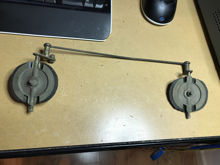
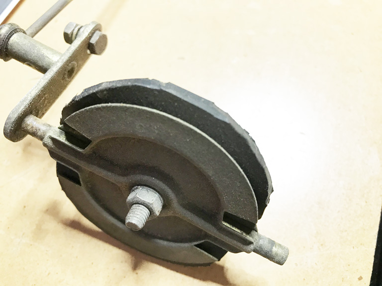
Looking forward to purchasing 914Rubber foam seals.
Should you decide to remove the impeller the 1st step is to get the spring clip off. I did it by gently prying the clip upward until I could get ahold of it with expanding snap ring pliers. 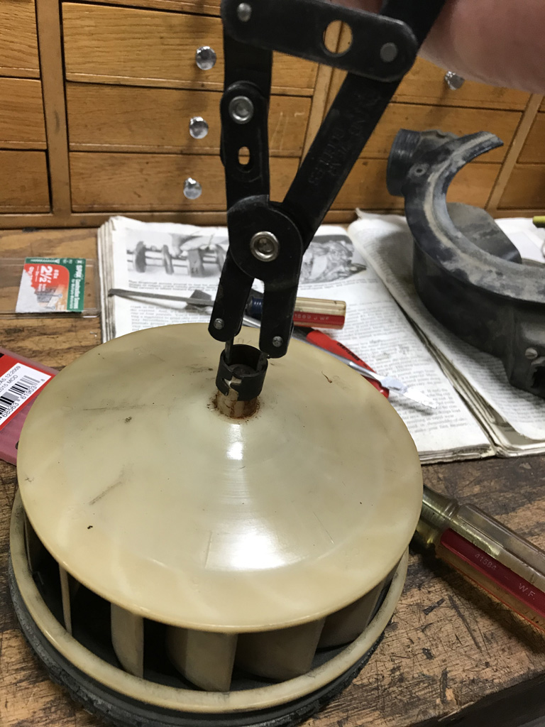
In the cascading events that lead me to remove the motor from the housing / frame, it lead to a complete FUBAR situation. The permanent magnets and a bunch of spring clips that hold the magnets inside the housing came out along with the motor frame. I had assumed the permanent magnets would be secured to the housing. They were. However the glue that was holding them was so old, they just slipped right out of the frame along with the rest of the armature frame assembly. I don't see this ever going together properly again! Given the result, I would not recommend trying to remove the motor from the housing unless you're planning to replace the complete motor assembly.
Brushes weren't designed to be serviced, though it could be done if need be by unsoldering them, and carefully bending the retainers to get the brushes out. But, truly not designed for service. 
The other is the motor shaft bushings are not designed for service. If they are worn and allowing side play and vibration like mine was, I don't really seee a viable way to service them even with the entire motor frame readily in my hand. 

Posted by: Mikey914 Jan 28 2021, 10:33 AM
Can you post up some close up pics of the unserviceable part. Perhaps we can make a part that allows replacement of the one side that is an issue?
Posted by: DRPHIL914 Jan 28 2021, 10:58 AM
Warning: Carnage that can ensue trying to disassemble the blower motor
First up someone was clearly here before and made some creative rubber seals for the blower motor control vanes.
Looking forward to purchasing 914Rubber foam seals.
Should you decide to remove the impeller the 1st step is to get the spring clip off. I did it by gently prying the clip upward until I could get ahold of it with expanding snap ring pliers.
In the cascading events that lead me to remove the motor from the housing / frame, it lead to a complete FUBAR situation. The permanent magnets and a bunch of spring clips that hold the magnets inside the housing came out along with the motor frame. I had assumed the permanent magnets would be secured to the housing. They were. However the glue that was holding them was so old, they just slipped right out of the frame along with the rest of the armature frame assembly. I don't see this ever going together properly again! Given the result, I would not recommend trying to remove the motor from the housing unless you're planning to replace the complete motor assembly.
Brushes weren't designed to be serviced, though it could be done if need be by unsoldering them, and carefully bending the retainers to get the brushes out. But, truly not designed for service.
The other is the motor shaft bushings are not designed for service. If they are worn and allowing side play and vibration like mine was, I don't really seee a viable way to service them even with the entire motor frame readily in my hand.
i was afraid of something like that happening when and if i got that circular spring clip off the back, i think it may be better to get a new assembly with motor and install that. the URO one i have seen as cheap as $83, on ebay and other sellers Pelican was the most at $95,
very creative on the flapper seals, the other box i rebuilt 2 years ago with the main body seal and flapper seals from 914rubber were a tight but proper fit and will make that work fine. I still have to pull that one out of my car because i have to go thru this whole process of testing the contacts like we are doing on these 2, thats the one that only runs on one speed, medium. I plan on rebuilding all 3 of these unless this resistor pack is bad on #1, if so i will have to buy a good used one from someone that may have one that the rest of the housing is not worth rebuilding or isnot going to.
I do get about .5-1 testing lead to lead, so it may be the numbers i reported are slightly hig
Posted by: Superhawk996 Jan 28 2021, 07:11 PM
Note: Really need to remove resistor pack to do this properly.
When I removed mine, I found the low speed resistor bi-metallic switch was deformed closed. However, due to corrosion on the switch it was actually reading as if the switch were open. Can't assume anything. 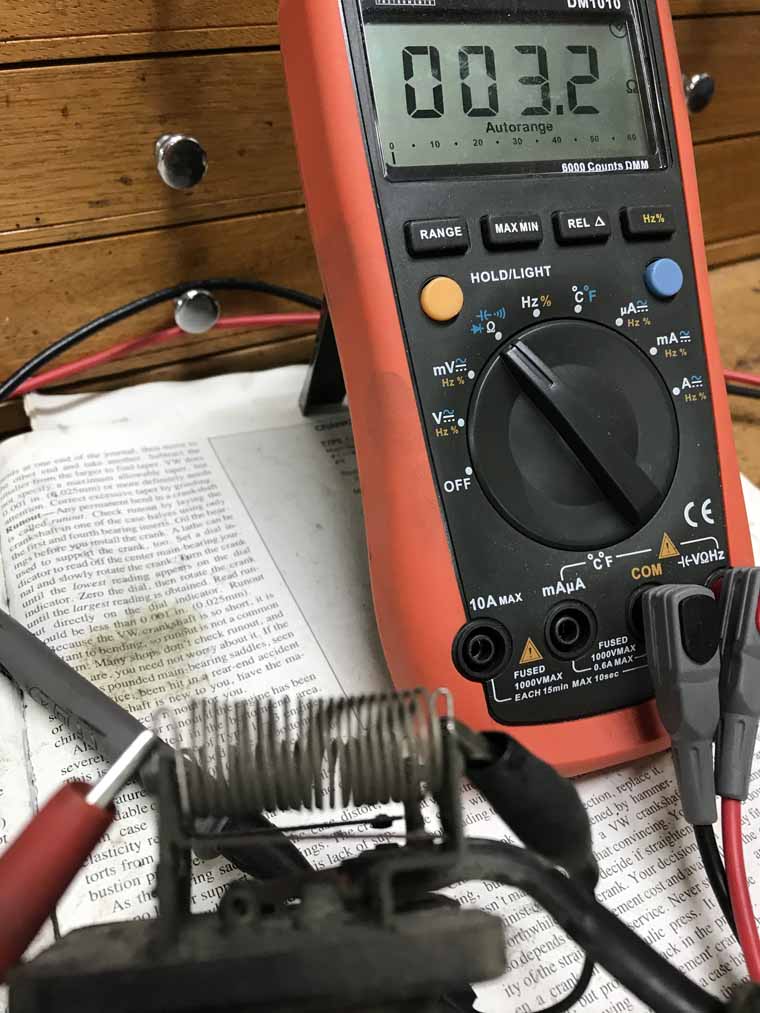
So reminder on the contact positions and keyway positions. 
Let's roll though the verification of the resistor
Here is the low speed after I filed the bi-metallic switch contact lightly with an ignition file. Because the bi-metallic switch is closed and now making contact it's measuring as a 1.1 ohm short across the resistor - bascially acting like a high speed bypass. 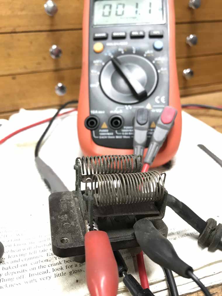
Note: from here on out I have the resistor bank leads that would normally go to the motor shorted together in same manner as @http://www.914world.com/bbs2/index.php?showuser=11106 was doing previously
Now low speed again with the bi-metallic switch bent back to open position with a pair of pliers to put it where it should be. 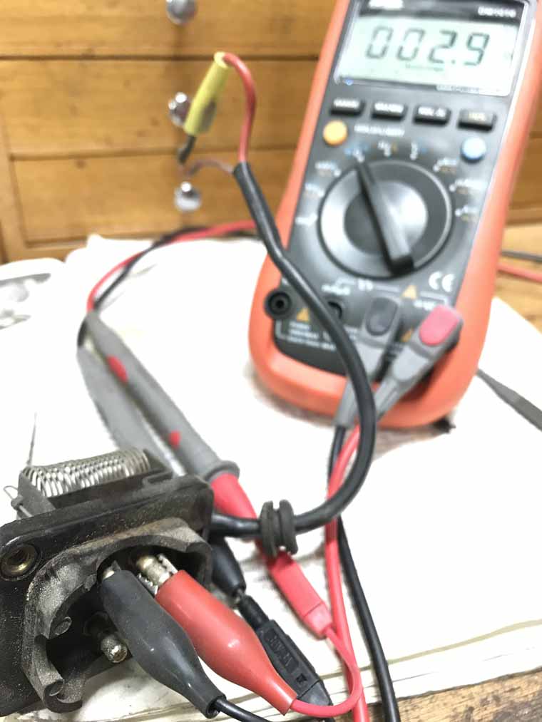
Medium speed with bi-metallic switch open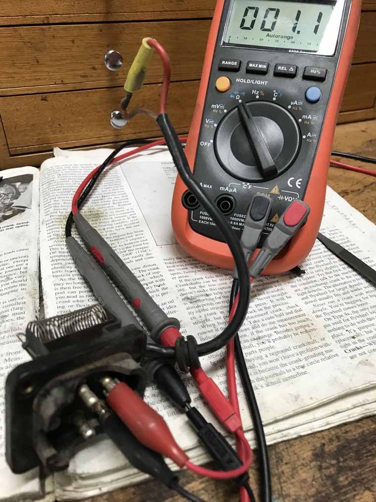
High speed (no resitor, and no bi-metallic switch for this one basically a direct short). 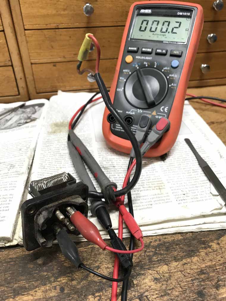
Finally here is a picture of the orientation of the resistor bank connector and keyway as I photographed it in the photos above. 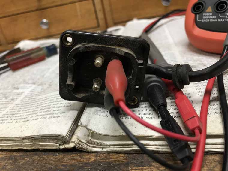
I also did measure the armature of my now defunct motor -- the armature of the motor measured in the range of 0.8 ohms to 1.2 ohms depending on where it was rotated to.
So if you're measuring the resistor bank in the as installed postion, you would expect all values above to have 0.8 - 1.2 ohm added to them. This correlates pretty well to what I measured initially on my blower motor + resistor as an assembly. 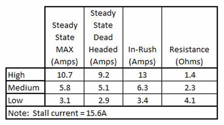
Posted by: Superhawk996 Jan 28 2021, 07:31 PM
@http://www.914world.com/bbs2/index.php?showuser=3348
Here is the motor frame. 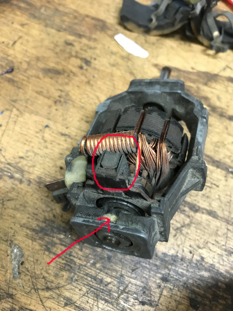
The motor brush is circled in red. In order to service it the tab would have to be bent open, the brush desoldered from the inductor / solder tab and then a new one installed. Not impossible but it's definately not designed for service.
The arrow pointing to the bushing on the open end of the motor does appear to have a small spot that can be oiled on some exposed felt. The impeller end of the motor frame doesn't have this same opening. Sort of makes sense since the impeller effectively prevents you from servicing that end of the motor.
On my blower motor I have excesive radial play in the impeller end bushing which would logically wear 1st since the impeller is cantilevered off this end. That radial play allowed it to vibrate and squeal intermittently until it warmed up.
The bushing is esentially staked into the pot metal motor frame. Wouldn't be easy to unstake it and then replace the bushing and re-stake. I'm a cheap SOB but really that would have been more work than I'd want to do. At that point, I really needed a new motor.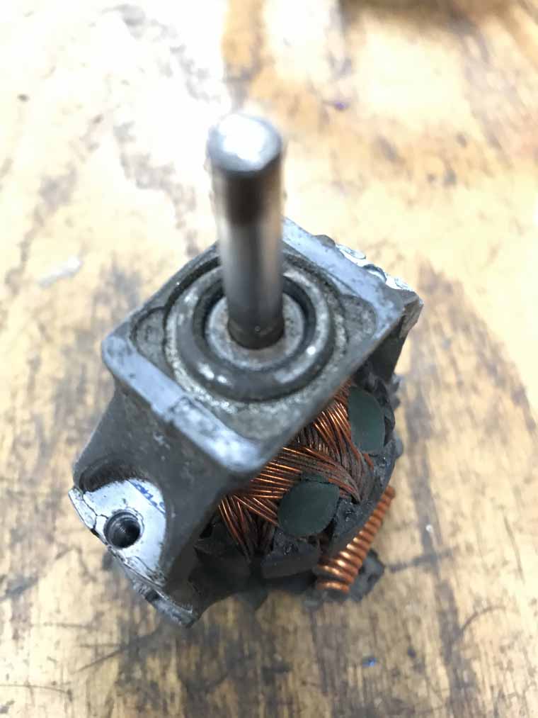
Hope all this can help someone someday!
Posted by: Mikey914 Jan 28 2021, 08:12 PM
Bosch has motors listed for these. If you have removed the unit this far you can save a few $ and get the Bosch brand. I have seen them for al little as $65 at one point.
Posted by: Superhawk996 Jan 28 2021, 08:41 PM
Bosch has motors listed for these. If you have removed the unit this far you can save a few $ and get the Bosch brand. I have seen them for al little as $65 at one point.
@http://www.914world.com/bbs2/index.php?showuser=3348
Would be curious to see what you're thinking of. Do you have a part number?
I'll do a little digging too. I'm only aware of the URO part. However, I think it really does look like what maybe a off the shelf motor with some sort of molded adapter to fit this 914 blower housing frame that this smaller motor frame was a part of.
Posted by: DRPHIL914 Jan 28 2021, 09:59 PM
Bosch has motors listed for these. If you have removed the unit this far you can save a few $ and get the Bosch brand. I have seen them for al little as $65 at one point.
@http://www.914world.com/bbs2/index.php?showuser=3348
Would be curious to see what you're thinking of. Do you have a part number?
I'll do a little digging too. I'm only aware of the URO part. However, I think it really does look like what maybe a off the shelf motor with some sort of molded adapter to fit this 914 blower housing frame that this smaller motor frame was a part of.
@http://www.914world.com/bbs2/index.php?showuser=22428
good work! the Bosch motor i have found on ebay, multiple sellers, about $75-85, and Bosch does the fan/motor assembly for about $250, so a few options depending on your time and $$ available.
i am going to get a URO assembly for one of these, i have one good motor/fan/resistor from Al , that one will get reassembled once cleaned and new seals all come from Mark and we will document the whole rebuild and assemble, retest and reinstall.
that will wait for a week as i will be gone this weekend and parts are not in yet.
Posted by: Mikey914 Jan 29 2021, 12:41 AM
The only thing you could have a problem with the URO part is the balancing "weights" I haven't seen any on their unit. Also the fins may not be identical to hold them on so if it's less and you can reuse your weights because you have disassembled far enough I would personally use the OEM.
Posted by: Superhawk996 Jan 29 2021, 07:04 AM
For what it's worth good luck balancing one of these fan impellers.
They are dynamically balanced using a tachometer and an accelerometer.
You'll notice the impeller has degree markings on it. The tachometer keeps track of RPM as the impeller/motor assembly is spun. The accelerometer is used to find at what angle the peak acceleration occurs.
Knowing that information, a weight can be installed 180 degrees off of the peak acceleration. Rinse lather repeat until vibration is minimized.
Not easy to duplicate in our hobby garages. Static balance would achieve very little.
It can be done in a trial and error way in the same way you might balance a home ceiling fan with a penny. The problem with this is 1) they spin way faster which means a very small weight has quite a large effect. 2) They have so many vanes on the impeller you have a lot more trial and error options on where to place the weight. 3) Determination of minimal vibration becomes highly subjective.
My bet is that is why the OEM motor/impeller assembly costs the money it does vs. the URO assuming it isn't balanced.
Posted by: DRPHIL914 Jan 29 2021, 12:16 PM
For what it's worth good luck balancing one of these fan impellers.
They are dynamically balanced using a tachometer and an accelerometer.
You'll notice the impeller has degree markings on it. The tachometer keeps track of RPM as the impeller/motor assembly is spun. The accelerometer is used to find at what angle the peak acceleration occurs.
Knowing that information, a weight can be installed 180 degrees off of the peak acceleration. Rinse lather repeat until vibration is minimized.
Not easy to duplicate in our hobby garages. Static balance would achieve very little.
It can be done in a trial and error way in the same way you might balance a home ceiling fan with a penny. The problem with this is 1) they spin way faster which means a very small weight has quite a large effect. 2) They have so many vanes on the impeller you have a lot more trial and error options on where to place the weight. 3) Determination of minimal vibration becomes highly subjective.
My bet is that is why the OEM motor/impeller assembly costs the money it does vs. the URO assuming it isn't balanced.
makes sense , every one i have opened up has different amounts and local of metal clips on fins that i assume are the balancing weights .
good point on the balancing, maybe Drew aka @uropartsguy will chime in and tell us if any balance testing is done
Posted by: UROpartsman Feb 1 2021, 02:09 PM
The fan cage used in high quality URO Parts Blower Motor assembly https://apaindustries.com/parts/12265 is indeed dynamically tested at the factory. Just pulled two random units off the shelf in the warehouse; one has a balancing clip and the other doesn't (probably didn't need it). Our impeller doesn't have degree marks, but it does have an arrow mark that's aligned with a small hole that's probably a reference point for an optical eye in the balancing device, and a screen tells the operator where to place the clip on the cage relative to the arrow.
We sell a ton of these annually (also fits 911 up to 1989) and don't get any complaints.
Attached image(s)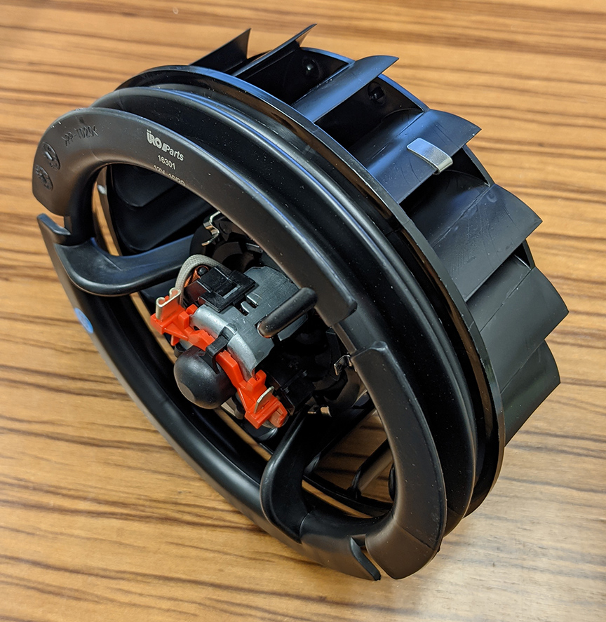
Posted by: Superhawk996 Feb 1 2021, 02:25 PM
The fan cage used in URO Parts Blower Motor assembly https://apaindustries.com/parts/12265 is indeed dynamically tested at the factory.
@http://www.914world.com/bbs2/index.php?showuser=19288
 That is awesome. Thank you for chiming in and confirming that my asssumption was erroneous.
 This blower motor assembly is looking like an even better, more viable option knowing the fan is balanced.
Out of curiosity, I'm looking for weight savings anywhere I can find them. Your blower motor housing looks to be injection molded plastic vs. the orignal cast pot metal frame.
I suspect the new DC motors are also lighter than stock.
Would you be so kind as to weight a unit? I just received a 2nd blower/housing to replace my housing that was all busted up. I'll weigh this stock one.
I would be be game to migrate to a new URO unit even if it only saves some weight of about 1/2 lb or so.
Posted by: DRPHIL914 Feb 1 2021, 02:38 PM
@http://www.914world.com/bbs2/index.php?showuser=19288
@http://www.914world.com/bbs2/index.php?showuser=22428
Drew thanks for the information, i have a good stock one but we have been working on figuring out the resistor packs. I am going be ordering one of these soon for one of the fan housings that i am rebuilding. I see a lot of them on ebay i assume the are all the same? look the same , some sellers like partscontainer carry them and price varies slightly but not much. We will document the build and testing of the unit here as well if thats ok? as soon as i can get one in i will put it in unit #2 . fyi 914 rubber now makes that main seal that goes in the fan so a nice complete restoration can now be accoplished as long as that darn resistor pack is good!
Phil
Posted by: UROpartsman Feb 1 2021, 07:04 PM
I would be be game to migrate to a new URO unit even if it only saves some weight of about 1/2 lb or so.
No problem, the one in our photo weighs 556g / 1.226 lbs. How much does the OE weigh?
All of the URO brand units should be the same, don't believe we've made any running changes to these. These come in a plain brown box with a white and blue URO sticker, and a URO logo laser-marked as shown in the above photo. Documenting the build and testing would be fantastic, looking forward to it!
Posted by: Superhawk996 Feb 1 2021, 07:33 PM
No problem, the one in our photo weighs 556g / 1.226 lbs. How much does the OE weigh?
2.63 lbs Just the pot metal motor frame alone (no motor at all, no impeller, etc.) weighs in at at a portly 1.46 lbs.
I can see a URO unit in the future!
Never realized that there were variations in the motor's and frames, but now looking back at Doc's photos, I see his motor and frame is different than what I had.
Guess VW may have had multiple sources for supply chain reasons or maybe just migrated to more efficient materials later on.@http://www.914world.com/bbs2/index.php?showuser=11106
@http://www.914world.com/bbs2/index.php?showuser=19288
Posted by: DRPHIL914 Feb 3 2021, 07:29 PM
No problem, the one in our photo weighs 556g / 1.226 lbs. How much does the OE weigh?
2.63 lbs Just the pot metal motor frame alone (no motor at all, no impeller, etc.) weighs in at at a portly 1.46 lbs.
I can see a URO unit in the future!
Never realized that there were variations in the motor's and frames, but now looking back at Doc's photos, I see his motor and frame is different than what I had.
Guess VW may have had multiple sources for supply chain reasons or maybe just migrated to more efficient materials later on.@http://www.914world.com/bbs2/index.php?showuser=11106
@http://www.914world.com/bbs2/index.php?showuser=19288
@http://www.914world.com/bbs2/index.php?showuser=22428
check it out- ebay listing of a fan motor like mine that has the metal surround not plastic,
i might get one- there are 4. Bosch motor.
https://www.ebay.com/itm/Front-Blower-Motor-For-74-89-Porsche-911-930-Speedster-Carrera-Turbo-PF52F9-/202604572614?_trksid=p2349624.m46890.l49292
Posted by: Superhawk996 Feb 4 2021, 09:38 AM
This is what I was calling the blower housing frame, not so much the motor housing itself. 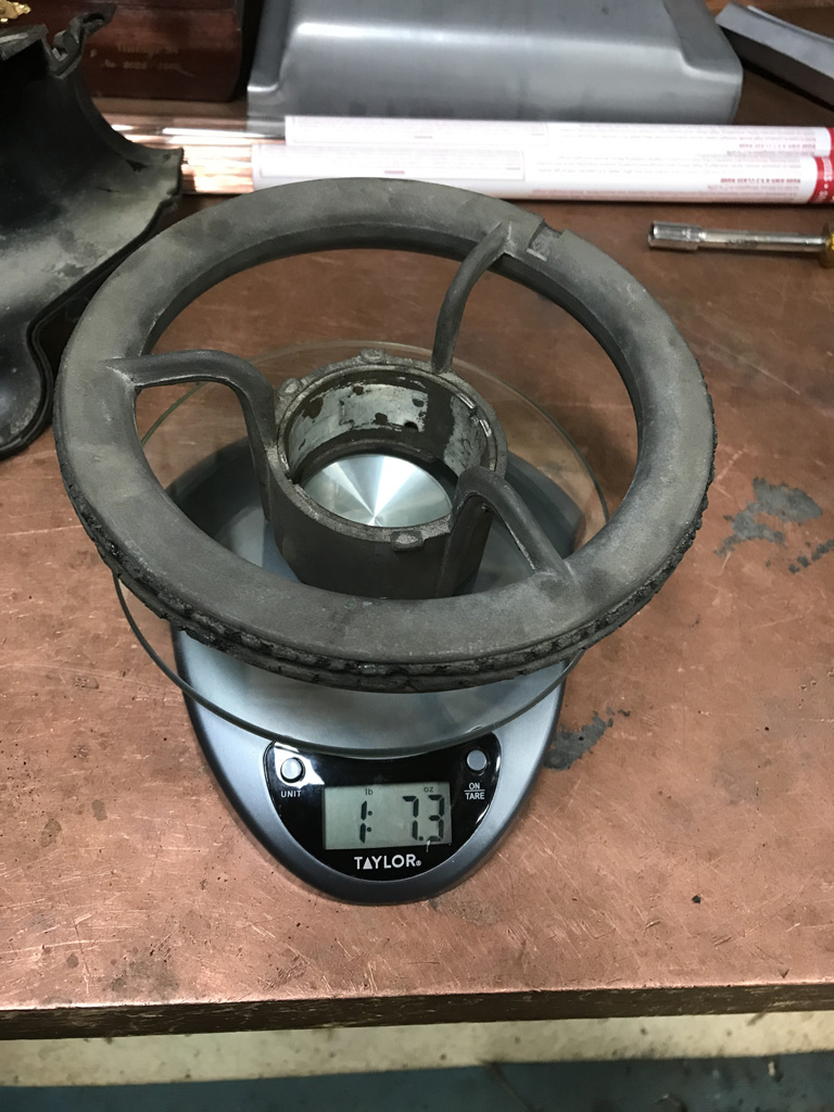
This is the heavy part!
The other motor frame is also cast pot metal and is an open metal frame. The permanent magnets were glued into the blower housing frame. Completely different DC motor construction than the motor you linked, and/or which appears to be in both your pictures and was part of the 2nd used fresh air box I recived.
Blower housing frame on left, DC motor with open frame in center, pile of permanent magnets, spring clips, and fasteners on the right. 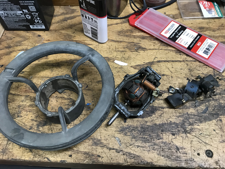
The newer type DC motor that are in the URO blower and that you linked to are way lighter than these parts.
Hard for me to put a vintage on these parts. My car is an early 73' but has backdated bumpers, early doors, and generally a mish mash of parts from who knows where. I suspect this is an early model based on motor construction, the inlet cowl seal, and the fact that it didn't have a plastic inlet grille but some homemade window screen!
@http://www.914world.com/bbs2/index.php?showuser=11106
Posted by: DRPHIL914 Feb 5 2021, 09:26 AM
The fan cage used in URO Parts Blower Motor assembly https://apaindustries.com/parts/12265 is indeed dynamically tested at the factory. Just pulled two random units off the shelf in the warehouse; one has a balancing clip and the other doesn't (probably didn't need it). Our impeller doesn't have degree marks, but it does have an arrow mark that's aligned with a small hole that's probably a reference point for an optical eye in the balancing device, and a screen tells the operator where to place the clip on the cage relative to the arrow.
We sell a ton of these annually (also fits 911 up to 1989) and don't get any complaints.
I would be be game to migrate to a new URO unit even if it only saves some weight of about 1/2 lb or so.
No problem, the one in our photo weighs 556g / 1.226 lbs. How much does the OE weigh?
All of the URO brand units should be the same, don't believe we've made any running changes to these. These come in a plain brown box with a white and blue URO sticker, and a URO logo laser-marked as shown in the above photo. Documenting the build and testing would be fantastic, looking forward to it!
well my new fan and motor assembly from URO arrived yesterday! so this will go in one of the fan housings that i have that will be rebuilt and sealed as soon as those parts arrive. I have one resistor pack that seems to be testing good , the other one i have to still figure out whats wrong with it before reassembly with the know stock oem fan and motor assembly, and the third one need a new motor so i ordered the brand new Bosch replacement motor to but into that fan, so 3 different ways to do this, depending on how deep you want to go, well even a 4th if you wanted to try and rebuild a motor but that does not appear to be possible on some of these according to how it looks from @Superhawy996 experiment turned out. he can confirm that, but the Fan/and motor assembly from URO is under $90. We just have to get the fan/housing seal, which 914rubber now makes, along with the flapper seals and seal for the lower fan to upper housing(diverter box).
Now if we could source a new or OEM NOS stock of resistor packs i could do a nice rebuild service with new seals, motor, fan and resistor pack.
Posted by: UROpartsman Feb 5 2021, 10:57 AM
Awesome Phil, keep us updated!
Posted by: DRPHIL914 Feb 8 2021, 09:00 AM
@http://www.914world.com/bbs2/index.php?showuser=3348
@http://www.914world.com/bbs2/index.php?showuser=22428
for superhawk, update on my 2 fans with testing the resistor packs, with new leads and cleaning contacts etc i get same readings for both of these, low medium and high are at or close to normal range. I think both are good, so i will assemble each in a cleaned up housing with new seals, one will hvae my brand new fan from URO and the other will have the new used one that tests good from Al Merideth, good free turning fan i bench tested it yesterday.
But @http://www.914world.com/bbs2/index.php?showuser=3348 no care package no seal or rebuild kit has arrived, this project is stopped until i get the seals from 914rubber.
Mark, i will buy 2 additional kits too with all the seals including the new big fan to housing seal and the flappers seals and lower to upper housing seals., along with hardware.
If you can have the staff email me a paypal invoice i would like this sent out asap. thanks,
Phil
Posted by: Superhawk996 Feb 8 2021, 09:18 AM
@http://www.914world.com/bbs2/index.php?showuser=3348
I have received a seal kit but wasn't able to get ahold of a seal for blower housing to the blower frame. Would really love to see you making these, that would allow for a total rebuild of foam seals.
Like @http://www.914world.com/bbs2/index.php?showuser=11106 . . . if you want to send me an invoice for a blower frame gasket, I'll glady pay to be the beta tester 
Posted by: Superhawk996 Feb 8 2021, 09:29 AM
@http://www.914world.com/bbs2/index.php?showuser=3348
for superhawk, update on my 2 fans with testing the resistor packs, with new leads and cleaning contacts etc i get same readings for both of these, low medium and high are at or close to normal range. I think both are good,
@http://www.914world.com/bbs2/index.php?showuser=11106
If you're getting similar readings between Medium and High Speeds, I'm thinking that your DMM is having resolution issues at very low ohm readings.
Might be time to upgrade the DMM. I'm always a fan of Fluke but let's be honest, that is big money for a hobby meter.
I've used HF meters with good sucess - not pro grade but not bad for hobby use. I consider them to be "burner" DMM's. I prefer the newer AMES unit.
https://www.harborfreight.com/dm1010-professional-commercial-and-residential-multimeter-64021.html
I also have one of these around and found it to be OK but is sometimes a bit glitchy if you just turn it on and fly right to ohms settings. It sort of locks up intermittently. If you switch on, wait and then go to ohms, it's fine.
https://www.harborfreight.com/5-in-1-digital-multimeter-98674.html
I was maybe going to recommend an old school analog Pro grade meter but OMG . . . prices have gone way up. Price is now comparable to cost for a Fluke DMM.
https://www.grainger.com/product/1A587?cm_mmc=PPC:+Google+PLA&ef_id=EAIaIQobChMI_rbNy8va7gIV5Y1bCh3urgW0EAYYASABEgKdKvD_BwE:G:s&s_kwcid=AL!2966!3!264955916567!!!g!436873882706!&gucid=N:N:PS:Paid:GGL:CSM-2295:4P7A1P:20501231&gclid=EAIaIQobChMI_rbNy8va7gIV5Y1bCh3urgW0EAYYASABEgKdKvD_BwE
Gold Standard Fluke
https://www.mscdirect.com/browse/tnpla/52435369?cid=ppc-google-New+-+Lighting+%26+Electrical+-+PLA_sC5vtPhB1___164110844556_c_S&mkwid=sC5vtPhB1%7cdc&pcrid=164110844556&rd=k&product_id=52435369&pgrid=37806554820&ptaid=pla-468094330469&gclid=EAIaIQobChMIxvfpts7a7gIVzMDACh0IaAJ5EAQYBSABEgLxmfD_BwE
Posted by: DRPHIL914 Feb 8 2021, 10:19 AM
@http://www.914world.com/bbs2/index.php?showuser=3348
for superhawk, update on my 2 fans with testing the resistor packs, with new leads and cleaning contacts etc i get same readings for both of these, low medium and high are at or close to normal range. I think both are good,
@http://www.914world.com/bbs2/index.php?showuser=11106
If you're getting similar readings between Medium and High Speeds, I'm thinking that your DMM is having resolution issues at very low ohm readings.
Might be time to upgrade the DMM. I'm always a fan of Fluke but let's be honest, that is big money for a hobby meter.
I've used HF meters with good sucess - not pro grade but not bad for hobby use. I consider them to be "burner" DMM's. I prefer the newer AMES unit.
https://www.harborfreight.com/dm1010-professional-commercial-and-residential-multimeter-64021.html
I also have one of these around and found it to be OK but is sometimes a bit glitchy if you just turn it on and fly right to ohms settings. It sort of locks up intermittently. If you switch on, wait and then go to ohms, it's fine.
https://www.harborfreight.com/5-in-1-digital-multimeter-98674.html
I was maybe going to recommend an old school analog Pro grade meter but OMG . . . prices have gone way up. Price is now comparable to cost for a Fluke DMM.
https://www.grainger.com/product/1A587?cm_mmc=PPC:+Google+PLA&ef_id=EAIaIQobChMI_rbNy8va7gIV5Y1bCh3urgW0EAYYASABEgKdKvD_BwE:G:s&s_kwcid=AL!2966!3!264955916567!!!g!436873882706!&gucid=N:N:PS:Paid:GGL:CSM-2295:4P7A1P:20501231&gclid=EAIaIQobChMI_rbNy8va7gIV5Y1bCh3urgW0EAYYASABEgKdKvD_BwE
Gold Standard Fluke
https://www.mscdirect.com/browse/tnpla/52435369?cid=ppc-google-New+-+Lighting+%26+Electrical+-+PLA_sC5vtPhB1___164110844556_c_S&mkwid=sC5vtPhB1%7cdc&pcrid=164110844556&rd=k&product_id=52435369&pgrid=37806554820&ptaid=pla-468094330469&gclid=EAIaIQobChMIxvfpts7a7gIVzMDACh0IaAJ5EAQYBSABEgLxmfD_BwE
thanks for the recommendations, i will invest in a good one, i had a much better meter but it took a crap last year , need a good one with a good warranty
Posted by: Mikey914 Feb 8 2021, 05:10 PM
@http://www.914world.com/bbs2/index.php?showuser=3348
@http://www.914world.com/bbs2/index.php?showuser=22428
for superhawk, update on my 2 fans with testing the resistor packs, with new leads and cleaning contacts etc i get same readings for both of these, low medium and high are at or close to normal range. I think both are good, so i will assemble each in a cleaned up housing with new seals, one will hvae my brand new fan from URO and the other will have the new used one that tests good from Al Merideth, good free turning fan i bench tested it yesterday.
But @http://www.914world.com/bbs2/index.php?showuser=3348 no care package no seal or rebuild kit has arrived, this project is stopped until i get the seals from 914rubber.
Mark, i will buy 2 additional kits too with all the seals including the new big fan to housing seal and the flappers seals and lower to upper housing seals., along with hardware.
If you can have the staff email me a paypal invoice i would like this sent out asap. thanks,
Phil
Looks like I accidentally sent superhawk the care package
Please PM me your address and I can ship out tomorrow.
Mark
Posted by: Superhawk996 Feb 8 2021, 05:15 PM
@http://www.914world.com/bbs2/index.php?showuser=3348
@http://www.914world.com/bbs2/index.php?showuser=22428
for superhawk, update on my 2 fans with testing the resistor packs, with new leads and cleaning contacts etc i get same readings for both of these, low medium and high are at or close to normal range. I think both are good, so i will assemble each in a cleaned up housing with new seals, one will hvae my brand new fan from URO and the other will have the new used one that tests good from Al Merideth, good free turning fan i bench tested it yesterday.
But @http://www.914world.com/bbs2/index.php?showuser=3348 no care package no seal or rebuild kit has arrived, this project is stopped until i get the seals from 914rubber.
Mark, i will buy 2 additional kits too with all the seals including the new big fan to housing seal and the flappers seals and lower to upper housing seals., along with hardware.
If you can have the staff email me a paypal invoice i would like this sent out asap. thanks,
Phil
Looks like I accidentally sent superhawk the care package
Please PM me your address and I can ship out tomorrow.
Mark
@http://www.914world.com/bbs2/index.php?showuser=3348
@http://www.914world.com/bbs2/index.php?showuser=11106
oops -- I can also turn it around and ship to the Doc.
Posted by: Mikey914 Feb 8 2021, 05:21 PM
Go ahead and post up some pics. I will also be including some more new hardware you didn't know you need that were not included in the 1st package
Go ahead and keep it if you will use it.
Mark
Posted by: DRPHIL914 Feb 13 2021, 02:38 PM
@http://www.914world.com/bbs2/index.php?showuser=3348
@http://www.914world.com/bbs2/index.php?showuser=22428
here is my first batch of hardware and seals from 914rubber!!
now the fun can begin- i will need a second set of stuff to do the other box, but i am going to install a brand new fan into one unit, and a known good oem one in the other.
both need all new seals and will have a nice clean and restored fan housing (lowered half) i need a replacement top half if anyone has a mint one please PM me it’s the late type with the screen, the air/ water diverter part.
tonight i will do one rebuild and post the pics of the during and after .
- first pic is of the fan seal no one makes until now! all the ones i have opened had these seals in very poor shape, it’s a porous seal not solid like the new 914rubber seal.
Thanks again Mark and Matt!
Attached thumbnail(s)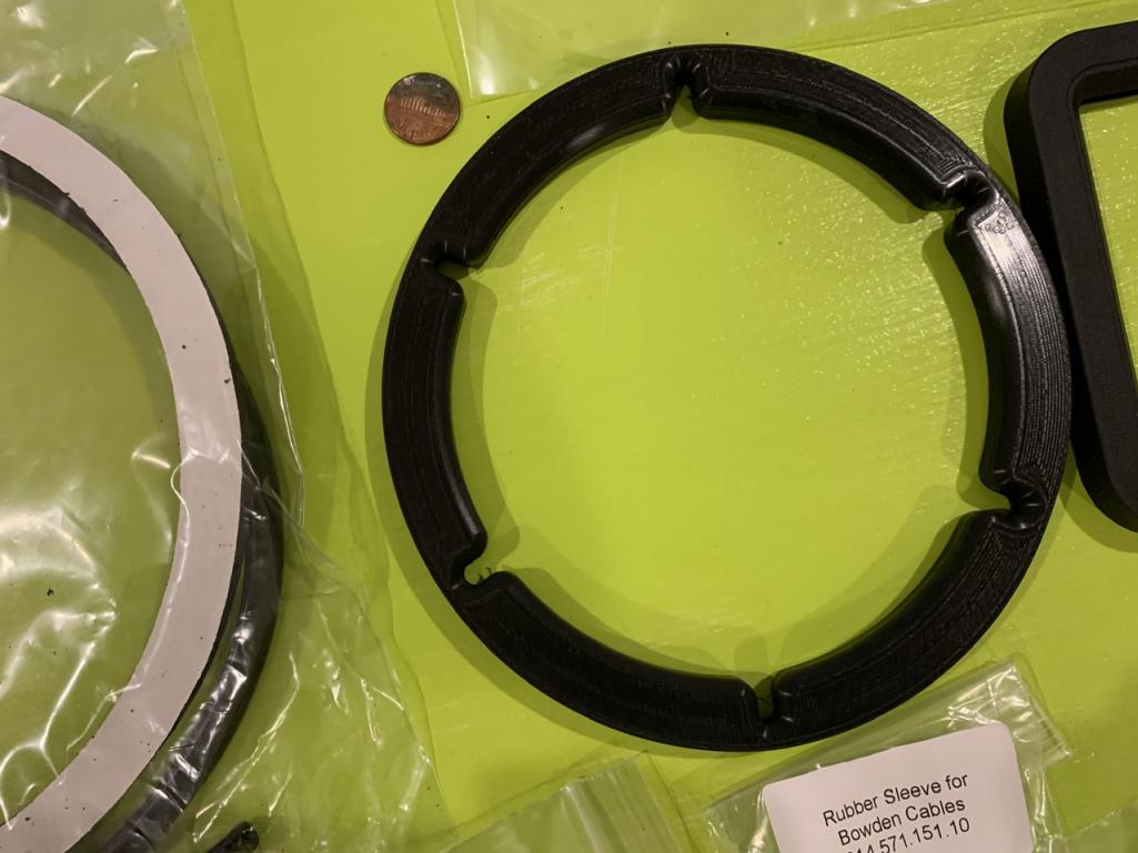
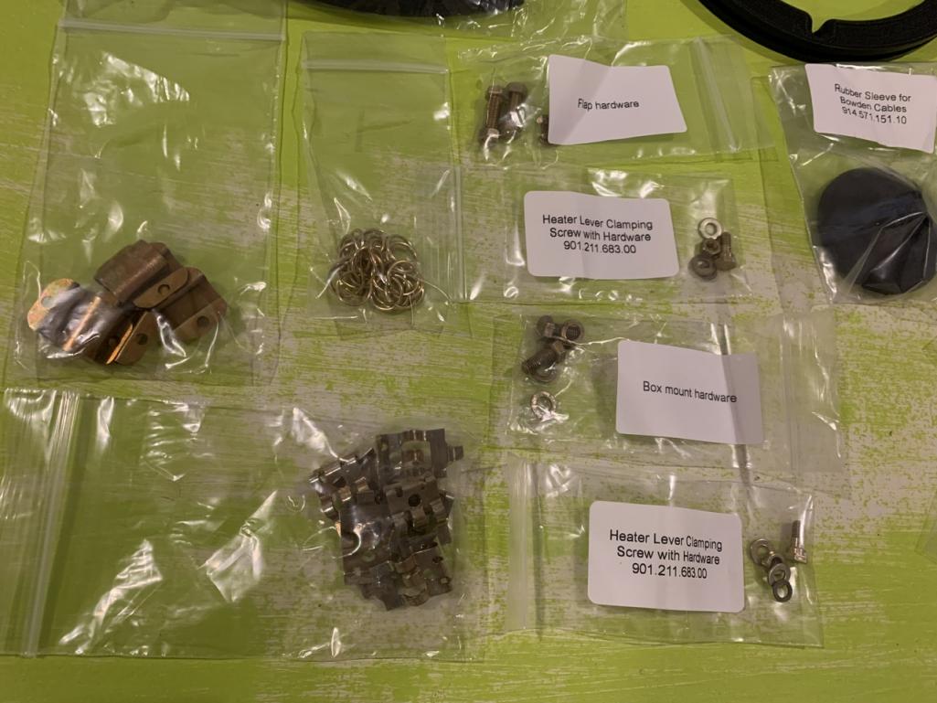
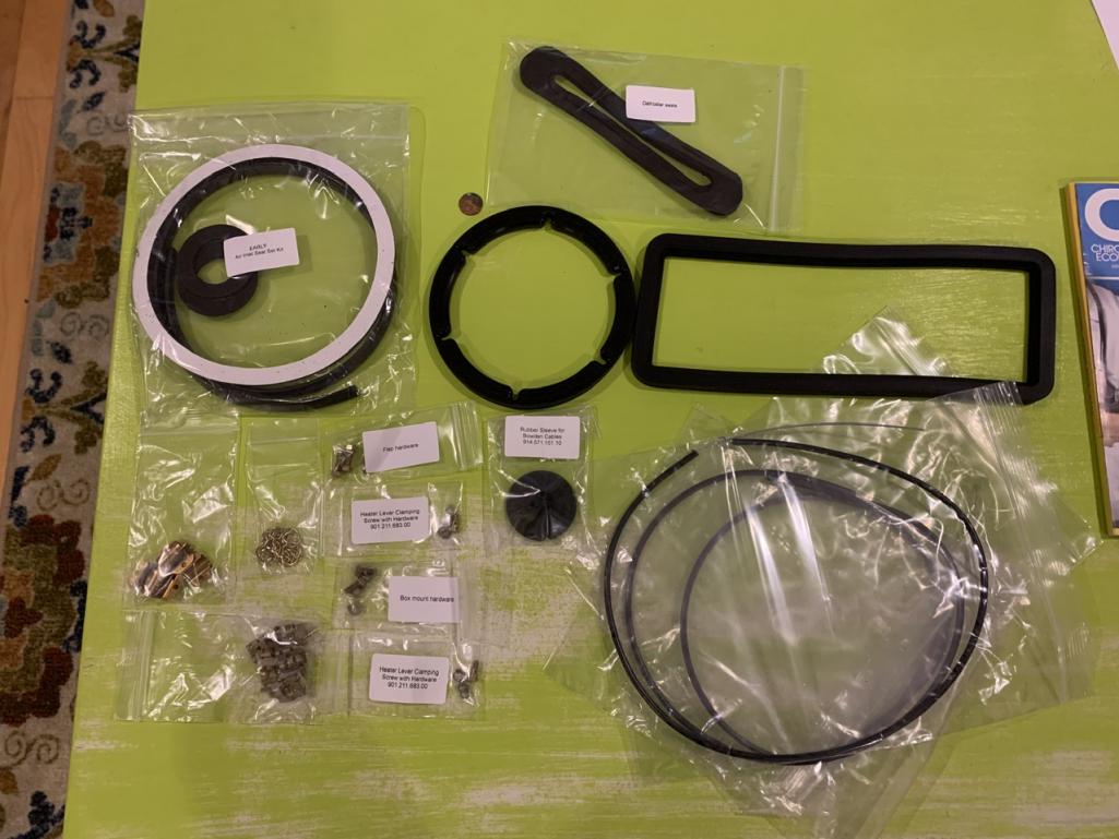
Posted by: Superhawk996 Feb 14 2021, 11:29 AM
@http://www.914world.com/bbs2/index.php?showuser=3348

You're killing me.
How do we get our hands on these goodies. Freshly plated omega clips would be outstanding. Same for the circular clips that hold the blower housing together. Blower frame to blower housing seal.
Not shown on website. Group buy?
Posted by: DRPHIL914 Feb 14 2021, 11:50 AM
@http://www.914world.com/bbs2/index.php?showuser=3348
You're killing me.
How do we get our hands on these goodies. Freshly plated omega clips would be outstanding. Same for the circular clips that hold the blower housing together. Blower frame to blower housing seal.
Not shown on website. Group buy?
yes he said there will be a group but soon, and should be listed both individually and as a kit soon, not sure of the timeframe but i’m sure he’ll chime in soon
Posted by: DRPHIL914 Feb 14 2021, 09:51 PM
i’ve had this apart for some time and finally had the time today to really clean it up and reassemble it now that the resistor pack has been verified as working. this one got the brand new URO motor and 914rubber seal and hardware.
also i cleaned it and decreased it , used a green scotch-brite pad and then polished with 5 step just like a paint correction, went from very dull to like new.
new flapper seals, the old ones were falling apart like dust . will ah e to drive the car this week to empty tank and then i can install the new fan box.
Attached thumbnail(s)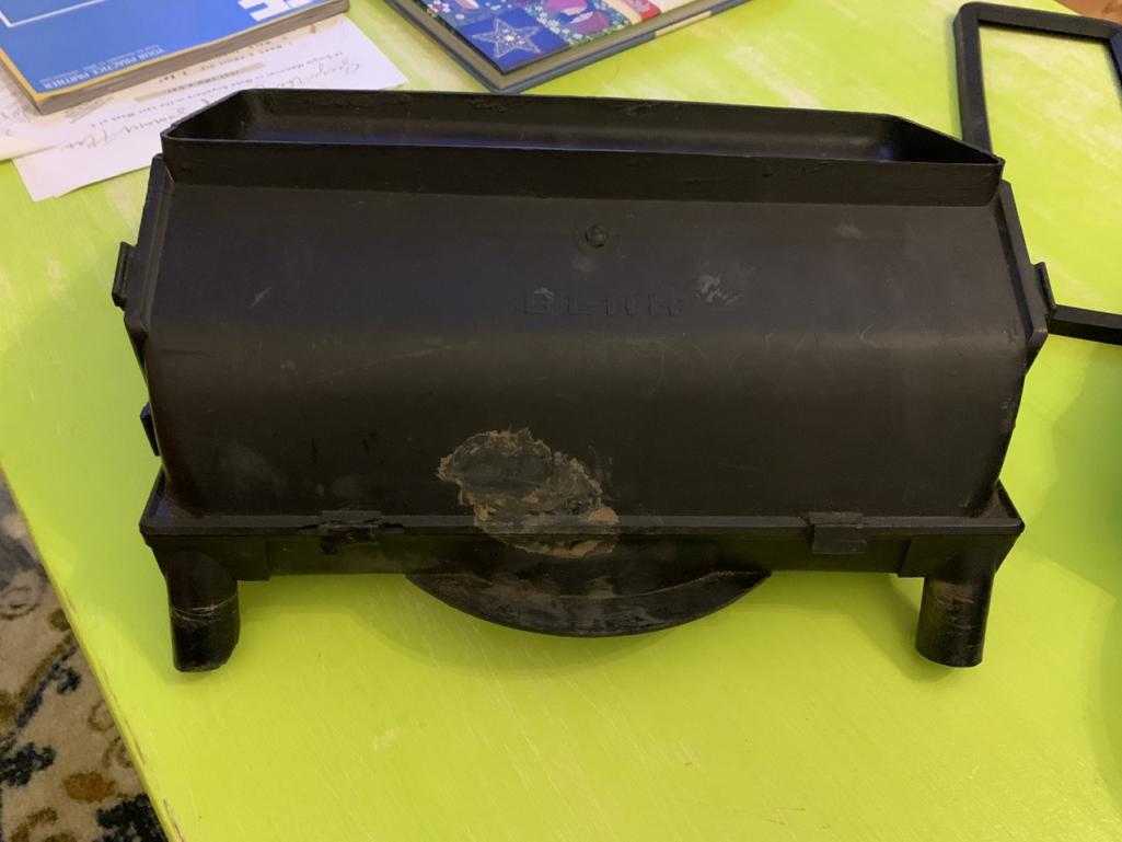
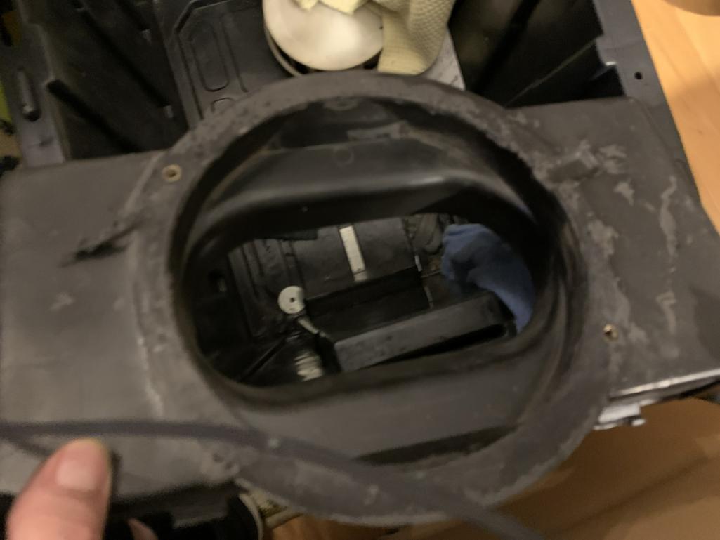

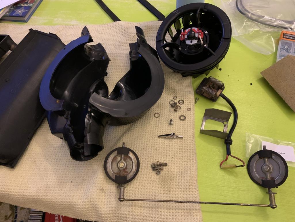

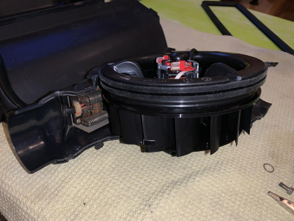


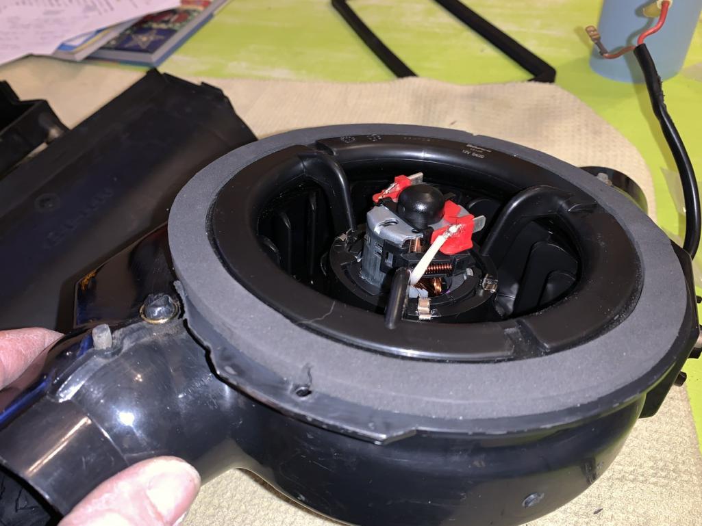
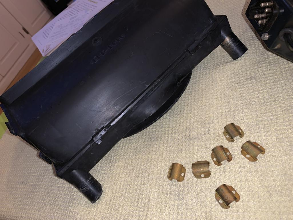
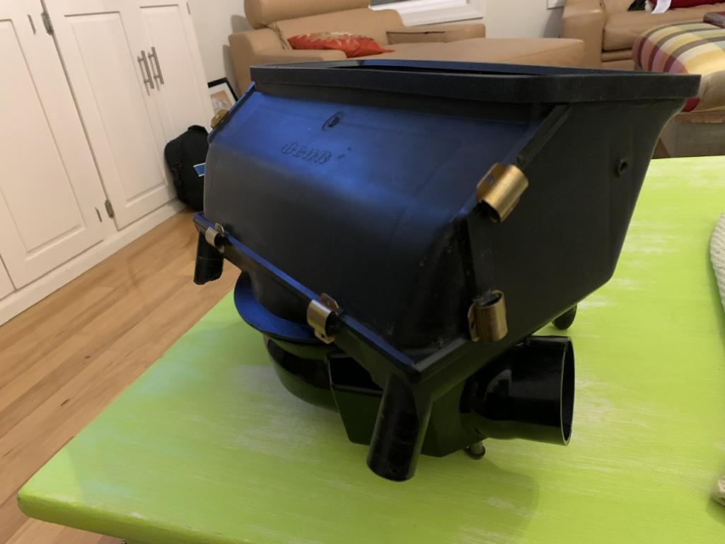
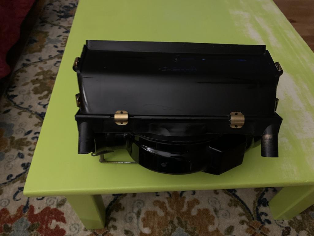
Posted by: DRPHIL914 Feb 14 2021, 10:03 PM
after polishing , overkill i know but might as well make it look as stood on the outside as on the inside. once i get to the point of installing it i will post again, i hAvr to change sour my controller and cables, which Mark also has and supplied with this kit.
the only thing i’ve not located that may keep some from restoring their box is new resistor assembly . in the end i found 2 boxes that had good ones. i have another box i will rebuild when i get new seals for it too, this one will go in my car , that one will be offered up for sale.
Attached thumbnail(s)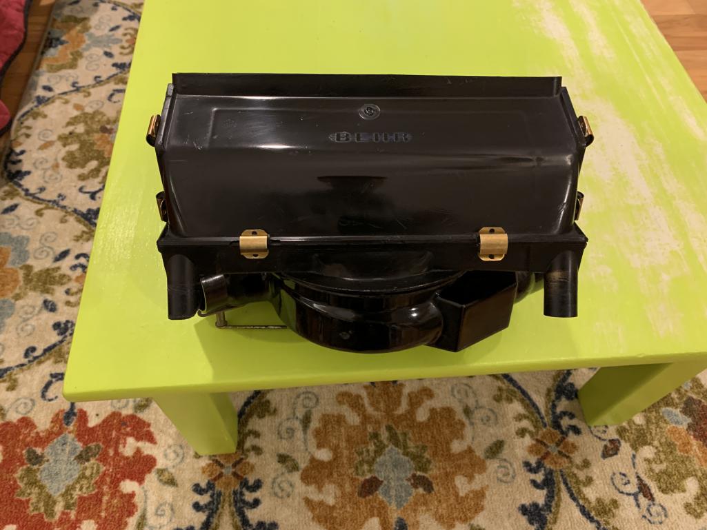

Posted by: DRPHIL914 Mar 23 2021, 08:19 AM
UPDATE:
finally got around to installing this new refurbished box, well not quite , i tested it first, and i only get one speed, same as before , and this is a new fan, resistor pack was tested for proper values, etc.
ok, first step i thought must be the controls, so i connected 2 other controllers that have cleaned contacts, and were tested before i bought them from the p.o. , same results.
the only explanation is that the wiring for the other 2 speeds is compromised, only the white/green wire allows for acompleted circuit once the slider attaches to that contact it is connected to. If i move the wire from the low to high connector then the fan will turn on but not on the other 2, so tonight i will experiment with a couple temp wires from the controls to the fan, i do think for some reason -
So the power goes from the fuse box to the fan and is hot from #8 fuse, and on with ignition. the circuit is completed when the lever is slid to right and the feeler contacts the selected connector and completes the circuit, low is just one wire, medium and high will have 2 feelers touching either #1&2 or #2&3. thus completing the circuit thru the different resistors , thru those and to the fan motor.
and one else ever have this senario?
Posted by: DRPHIL914 Mar 23 2021, 08:24 AM
tank up and box accessed- pretty clean under there.
box is out and i am not putting anything back until i have it figured out, and it’s tested . it may require in complete new wiring.
Attached thumbnail(s)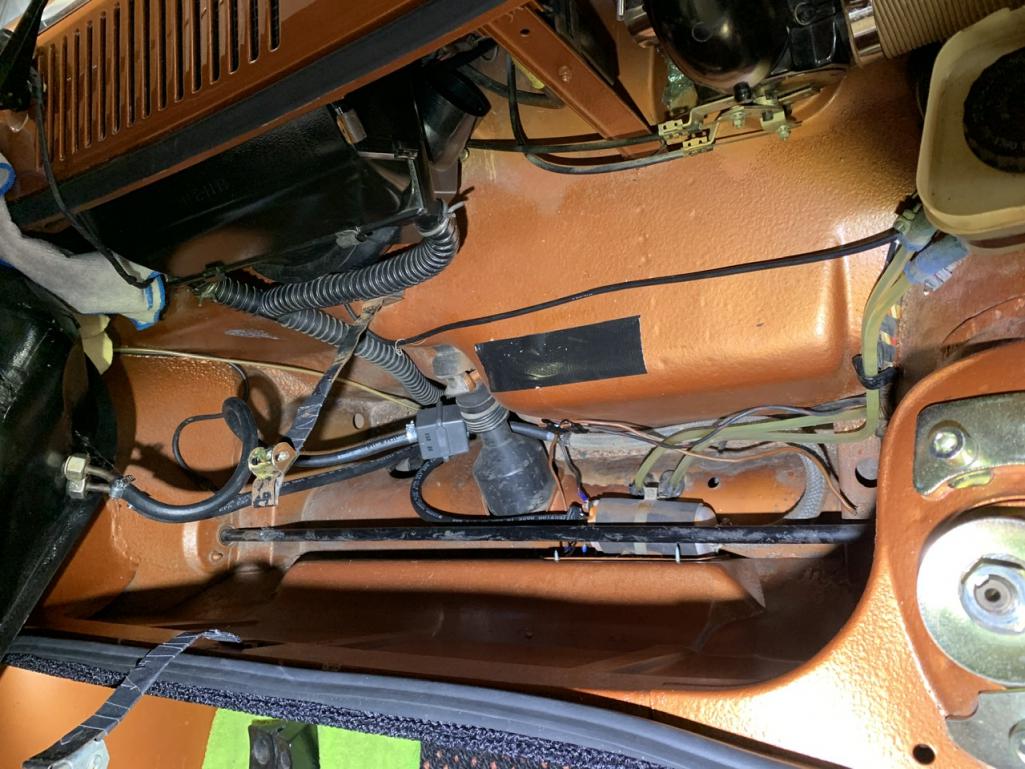
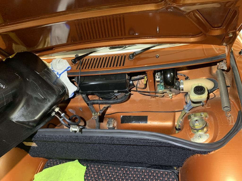
Posted by: bob164 Mar 23 2021, 02:39 PM
Don't think this is the issue with the fans, but the top picture shows a brown wire (usually a ground) that is just laying on the sheetmetal near the drivers side strut mount. You might look around for more loose wires and correctly attach them.
Posted by: DRPHIL914 Mar 24 2021, 04:59 AM
Don't think this is the issue with the fans, but the top picture shows a brown wire (usually a ground) that is just laying on the sheetmetal near the drivers side strut mount. You might look around for more loose wires and correctly attach them.
brown wire at bottom by the fuel pump is the ground for the pump,
Posted by: bob164 Mar 24 2021, 11:22 AM
The picture isn't that clear, was referring to the other end of the wire, can't tell if it is bolted to a ground point, or just dangling.
Posted by: DRPHIL914 Mar 25 2021, 06:39 AM
The picture isn't that clear, was referring to the other end of the wire, can't tell if it is bolted to a ground point, or just dangling.
good eye, i had not yet moved that wire, it was the original ground wire for the pump, i had installed the tank 2 years ago after restoration , had everything in place and discovered that the ground wire to the pump had come loose, so rather than pull the tank to get at the ground i ran a different wire for ground by accessing the pump thru the small access hole in the bulk head where the pump mounts on a '75 car. but i will get this one properly re attached before putting the tank back now.
Posted by: DRPHIL914 Mar 25 2021, 06:52 AM
ok update from trouble shooting last night,
after getting into this and finding i still could only get one speed on the fan,
@http://www.914world.com/bbs2/index.php?showuser=22428 reached out to me and he suggested a few other things to check before moving forward, so i wanted to eliminate the medium and high speed wires as being the issue by testing them for continuity.
Right now i do have the low speed working, the white/green wire.
both the white(medium) and the white/yellow(high) both test same resistance, 2.8-3.0 ohms same as the one that does work , so that seems to eliminate the wires as the issue.
i also ran a long jumper wire from the controller/sliders on each of those ground connections so with a new wire i get same result. which also in another way rules out the
wires, and i have also hooked up 2 separate control mechanisms to rule that out and same issue there same result.
this leaves me thinking i am back to considering the resistor pack as the issue. now when i had the unit out for restoration and installation of the new fan and seals we tested the resistance of those and they seem to have passed the test being at the correct ohm readings but maybe not. so--- i am going to look for a second resistor pack , if anyone had one that has bench tested please let me know, but until then i have 2 choices, one is just leave this in like it is and deal with it- hey i have one speed, a new fan that does work, but not on all 3 speeds, its just frustrating i cant get this 100% working.
i am about to just say screw it. - i am probably saying this due to being up until 2:30 am this morning doing this and then trying to get the f-ing box back into place- now the mounting screw on left side stripped out. - way too tight on the seal fit- @http://www.914world.com/bbs2/index.php?showuser=3348 this seal needs to be snug but not this tight, about 2mm less thick would help a lot in not having to use an f-ing crow bar to get the box squeezed up into place and bolted in......
Posted by: Rob-O Mar 25 2021, 07:27 AM
Quick question and I don’t have a schematic in front of me to verify. But are the controls fully installed in the dash? And by that I mean is it bolted to the firewall using the 10mm bolt? It’s a bit foggy but I seem to recall only having one speed until I bolted the controls to the firewall.
Posted by: DRPHIL914 Mar 25 2021, 10:22 AM
Quick question and I don’t have a schematic in front of me to verify. But are the controls fully installed in the dash? And by that I mean is it bolted to the firewall using the 10mm bolt? It’s a bit foggy but I seem to recall only having one speed until I bolted the controls to the firewall.
yes, it is.
oh and after reviewing again the schematic and my pictures and referencing another source, Superhawk996 had me go back and compare and due to my plug housing being cracked and gone, the wire had been crossed and i am pretty sure that they are not on the correct pin locations on the fan housing SO.... when i get home these will be moved, but i will test the unit first by using aligator clip to a chassis ground and test each separate ground on the pins, taking the control unit out of the equation. will see how this test goes , along with just verifying i have a full 12v at the fan coming from the fuse board. if its not, i have other issues..
Posted by: DRPHIL914 Mar 26 2021, 08:25 AM
OK finally last night i was able to sort thru the wiring issues, figure out the proper positions for the fan wires, verified all the connections, the DAPO had list the plug housing and had not put them back in correct positions, with that corrected the new fan tested out and all 3 speeds work perfectly. before reinstalling i tested the other controllers and verified working along with my other 2 fans, those do work but not as well as brand new, so those will get rebuilt with new fans and hardware and seals. i will have 2 lower fan units that will be available and i can vouch for the resistor packs in both testing and bench tested and fully functional. this will be for sale soon if anyone needs one.
i struggled with one upper box unit that had a crack and was slightly warped, so the seal would not fit, that one had to be trashed, luckily i have a couple, 2 good ones so back together with new seals and clips.
i used Ian’s video suggestions of using rubber bands to hold the sucker in place when reinstalling the box. the seals are tight but my biggest issue was the warping of the top edge of the box.
the other issue with this is you have to pull the tank that’s a pain.
a few pointers:
1. don’t forget to put the connection for the fuel level sender back on before the expansion tank is reattached.
2. put the air duct hoses on before the tank and expansion tank because the passenger side is almost impossible to do otherwise.
3. new cable slide so nice and smooth, put them in , it’s worth the time.
- and the air box cable must be attached before box is installed .
installing thie box would be a lot easier if that cable were longer, due to its length it’s so tight it’s hard to angle the box or pull it out far enough to get the box at the right angle to slide it into place.
4. use a clamp like Ian did in his video or a pry bar for leverage to push the box up into place far enough to ge the box mount screws into place.
So i hope i don’t have to do this in this car again, but i am glad after 12 years i finally have a full functional defrost fan, and wiper mechanisms, and soon to be a new 911 motorized windshield washer pump conversion too. , while all this was open i added the wiring and the washer tubing, which no longer goes into the cabin. i installed a Carmagic switch into the column with my new levers i got from 914sixer. so that can be installed this week too!
Done!!
@http://www.914world.com/bbs2/index.php?showuser=21811 Mark thanks for making all the great parts and seals for the air box,
914rubber is the only company that makes the fan to housing seal, the big round one, and the vent seals and flapper seals!
these are now in their site for sale.
@UROpartsguy Drew, thanks for the info on the fans and making an affordable part! the fan is perfectly balanced.
Attached thumbnail(s)
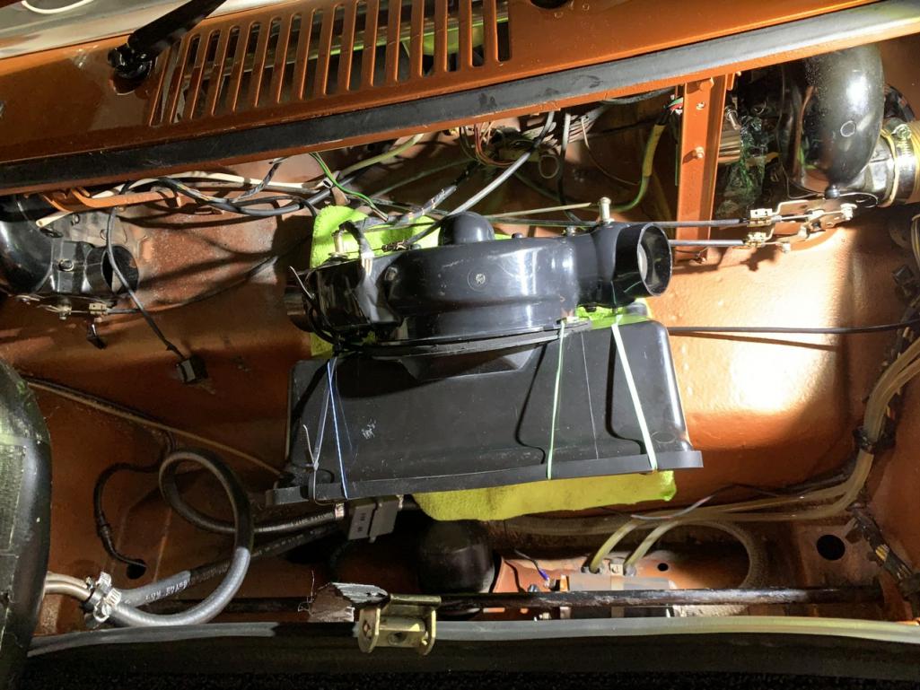
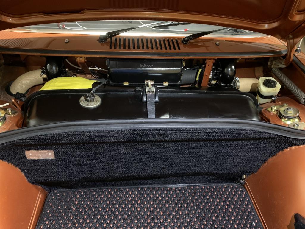

Posted by: DRPHIL914 Mar 26 2021, 08:35 AM
this is how the wiring should be connected.
i am missing the plastic plug so it was all messed up
Attached thumbnail(s)
Posted by: Mikey914 Mar 26 2021, 02:42 PM
Doing some research. Looks like we can form these easy enough.
To get the correct wire seems to be the issue. I'd have to buy a coil of it and its not cheap.
Posted by: Bullethead May 11 2023, 06:46 AM
A huge thank you to all the contributors of this thread! Currently attacking the blower restoration on my 6 and feel much more confident after reading this... 914 World rules.
Powered by Invision Power Board (http://www.invisionboard.com)
© Invision Power Services (http://www.invisionpower.com)