Printable Version of Topic
Click here to view this topic in its original format
914World.com _ 914World Garage _ Repairing Engine Tin
Posted by: seanpaulmc Feb 22 2021, 07:20 PM
I recommend all new welders to get some 50 year old thin gage sheet metal to learn with.  How hard could it be?
In doing so, you’ll practice with voltage and wire speed, stick out, part set up, metal cleaning, contamination and porosity, work area lighting, youtube, weld grinding, fabrication, clamping, gapping, blow thru, backing materials, warping, patience and wire brushing, to name a few.
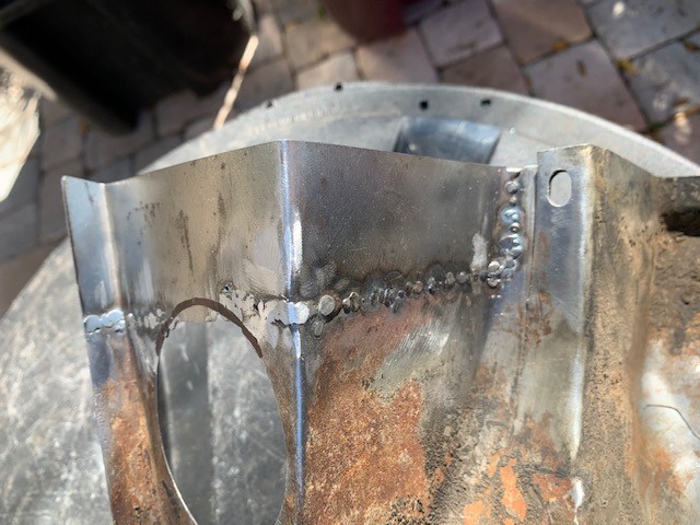
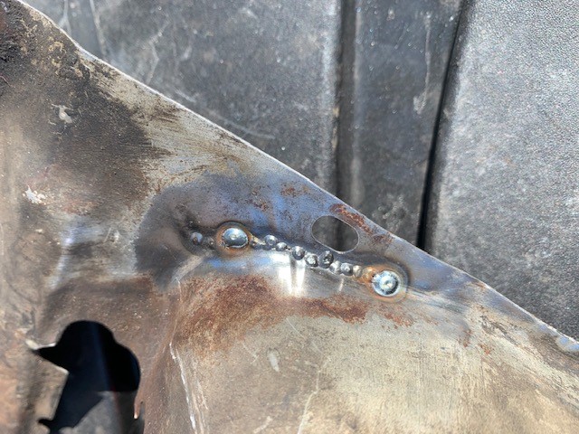
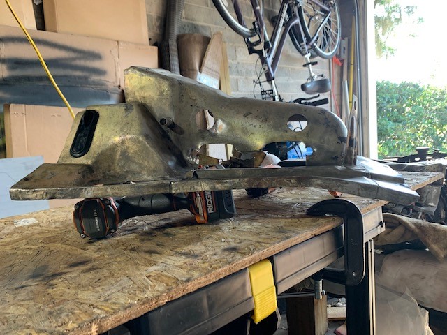
What I have...
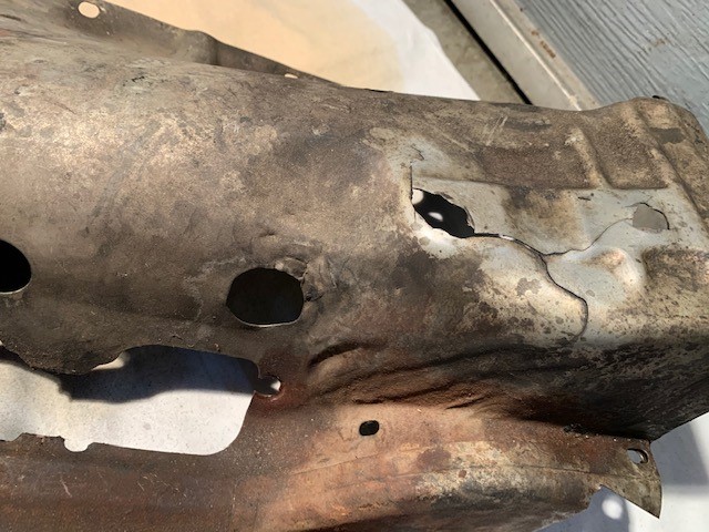
How many cracks can you spot?
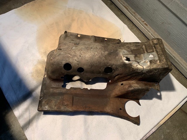
Save your original OG engine tin they say. It's the best they say.
So after a few hours...
I'm not kidding anyone here with these pictures, after many days I find myself with this... 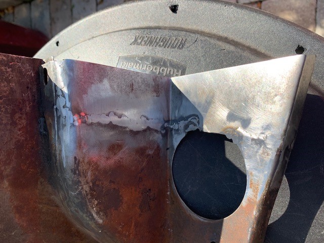
I have several questions for those with at least a few hours more experience.
1) How much more, if any, should these welds be ground down? Or, will the weld beads provide future strength to the thin, stretched sheet metal so leave as-is?
2) In order of preference, what would be the best three tools to use to grind down welds on thin sheet metal? Assume you don't have an air compressor. I don't.
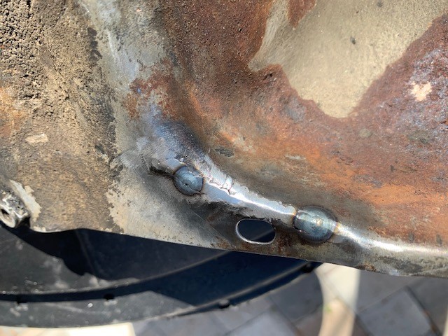
3) For the top section where the coil attaches on the tin, the coil bracket uses P/N: N 010 210 13 which is M 6 x 10 hex-head bolt. Is the tin supposed to have a captured nut on the backside or just thicker sheet metal in the locations that are missing on my tin (see first few pictures).
4) Should the coil mounting location be relocated in order to avoid whatever the hell happened here? If so, where?
In actuality I'm quite please with the results so far, maybe not the pace of the work, but at least the product thus far. It'll be useable tin and certainly better than it was.  This is literally the first time I have ever fabricated a patch and tried to weld anything. I'm working my way up to the easy stuff if there such a thing?
I appreciate you entertaining my questions.
Thanks,
Sean
Posted by: Archie Feb 22 2021, 07:54 PM

I recommend all new welders to get some 50 year old thin gage sheet metal to learn with. :welder: How hard could it be?
In doing so, you’ll practice with voltage and wire speed, stick out, part set up, metal cleaning, contamination and porosity, work area lighting, youtube, weld grinding, fabrication, clamping, gapping, blow thru, backing materials, warping, patience and wire brushing, to name a few.
What I have...
How many cracks can you spot?
Save your original OG engine tin they say. It's the best they say.
So after a few hours...
I'm not kidding anyone here with these pictures, after many days I find myself with this...
I have several questions for those with at least a few hours more experience.
1) How much more, if any, should these welds be ground down? Or, will the weld beads provide future strength to the thin, stretched sheet metal so leave as-is?
2) In order of preference, what would be the best three tools to use to grind down welds on thin sheet metal? Assume you don't have an air compressor. I don't.
3) For the top section where the coil attaches on the tin, the coil bracket uses P/N: N 010 210 13 which is M 6 x 10 hex-head bolt. Is the tin supposed to have a captured nut on the backside or just thicker sheet metal in the locations that are missing on my tin (see first few pictures).
4) Should the coil mounting location be relocated in order to avoid whatever the hell happened here? If so, where?
In actuality I'm quite please with the results so far, maybe not the pace of the work, but at least the product thus far. It'll be useable tin and certainly better than it was. :screwy: This is literally the first time I have ever fabricated a patch and tried to weld anything. I'm working my way up to the easy stuff if there such a thing?
I appreciate you entertaining my questions.
Thanks,
Sean
Hello Sean,
Regarding the welding techniques, please allow me to point you in THIS direction: https://www.youtube.com/watch?v=34bPn6lfyuA&list=UUB8HF8Pqug-Pc7DFqX9lf_g&index=4
He has an absolute encyclopedia of YouTube videos covering all aspects of bodywork welding and stuff with many handy tips and tricks which I dearly wish I'd known about when I started welding! ! Your welds don't look half-bad by the way! I'm a great believer in the no body-filler school of thought but it's tough to achieve.
To your questions:
1) I like to grind them down as much as possible, but that's just me!
2) See Trev's blog. He recommends a super-coarse flexible disc. I like an electric belt-sander as you can follow the weld bead.
3) There are two captive nuts, if memory serves.
4) I'll pass and let more knowledgeable types chip in.
Good luck and best wishes!
Posted by: cary Feb 22 2021, 08:34 PM
3" 36gr RoLoc on a 2" pad. Gives you a flexible edge.
Then tune with 2" 80gr.
My .02c.
Posted by: malcolm2 Feb 22 2021, 10:51 PM
Paint 'em and drive it.
Posted by: rfinegan Feb 23 2021, 04:51 AM
I just spent a few hours on mine last night. And I only had 1 inch tear near the spark plug hole. I was blowing hole though it everywhere!  Use .023 solid wire and tip with Argon mix and low power /feed setting helped a lot. Flux core was just too HOT!
For me I ground the top side flush for a nice finish and left the back side a little thicker for support and keep me from grinding back through.
You seem to be doing a fine job. A cut off wheel grinder and 3m roloc green discs cut the welds down fast and clean. If you want like new, buy a another set, but yours will work fine and clean up pretty good
Posted by: Mark Henry Feb 23 2021, 08:26 AM
Take a section of copper sheet or copper pipe and beat it flat, then back up the weld area with the copper. You still have to spot weld, but the copper backer stops it from blowing through and doesn't stick to the weld.
Posted by: Archie Feb 23 2021, 07:21 PM
Take a section of copper sheet or copper pipe and beat it flat, then back up the weld area with the copper. You still have to spot weld, but the copper backer stops it from blowing through and doesn't stick to the weld.
Great advice!
Posted by: Mark Henry Feb 24 2021, 08:56 AM
Take a section of copper sheet or copper pipe and beat it flat, then back up the weld area with the copper. You still have to spot weld, but the copper backer stops it from blowing through and doesn't stick to the weld.
Great advice!
Thanks

Thicker copper sheet holds up better but beating copper pipe flat is handy for backing up curved shapes and hàrd to get to areas. The copper has to be pressed against the weld area, if there's a gap it will blow through. The pipe is too thin of a material and will degrade quickly, but I just make another tool.
Posted by: Robarabian Feb 24 2021, 09:09 AM
Yes on the copper. Also, where you see the nice ring around the weld, that shows you made good penetration and that is what you are trying to do, fuse the metals together. If you dont have enough penetration, it won't hold. If you over penetrate, you burn through. It is a balance. If you see those rings, grind it flat.. and the advice about grinding first and then the flap disc 60-80 grit is where its at. Kudos for doing it on your own!
Posted by: rfinegan Feb 24 2021, 09:26 AM
Got this a Harbor Freight for a few bucks....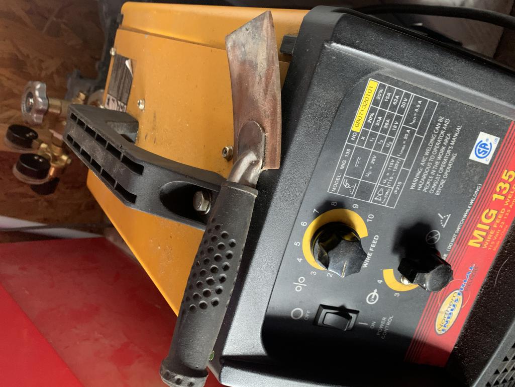
Posted by: dr914@autoatlanta.com Feb 24 2021, 10:09 AM
the passenger side 2.0 engine cylinder cover is impossibly hard to find as many have been cut (as yours has) for air conditioning. I applaud you in your job to fix this piece. HOWEVER when it gets this bad, could be easier to convert a 1.7 1.8 piece (readily available) by relocating the two spark plug holes. We are in the process of recreating the right front piece where the accelerator cable passes through. THIS piece is IMPOSSIBLE to find
Posted by: Mark Henry Feb 24 2021, 10:46 AM
the passenger side 2.0 engine cylinder cover is impossibly hard to find as many have been cut (as yours has) for air conditioning. I applaud you in your job to fix this piece. HOWEVER when it gets this bad, could be easier to convert a 1.7 1.8 piece (readily available) by relocating the two spark plug holes. We are in the process of recreating the right front piece where the accelerator cable passes through. THIS piece is IMPOSSIBLE to find
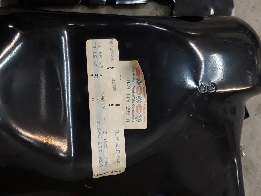
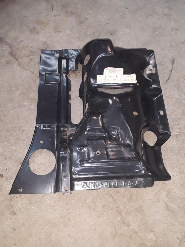
Like this one?
BTW I have the other side as well but it lost its label.
Attached thumbnail(s)
Posted by: bkrantz Feb 24 2021, 10:02 PM
For grinding welds on sheet metal I like flappy sanding disks on an angle grinder. Cuts quickly enough but less likely to grind holes than a solid disk.
Posted by: Superhawk996 Feb 25 2021, 06:58 AM
Like this one?
BTW I have the other side as well but it lost its label.
@http://www.914world.com/bbs2/index.php?showuser=17686
Wow - I've never seen NOS tin. Really interesting to see what they looked like originally.
Posted by: bbrock Feb 25 2021, 08:37 AM
For grinding welds on sheet metal I like flappy sanding disks on an angle grinder. Cuts quickly enough but less likely to grind holes than a solid disk.
You must have better technique than me. I tried them and was impressed with how quickly they ground down the welds but they put way too much heat into the piece.
Posted by: Mark Henry Feb 25 2021, 08:41 AM
Like this one?
BTW I have the other side as well but it lost its label.
@http://www.914world.com/bbs2/index.php?showuser=17686
Wow - I've never seen NOS tin. Really interesting to see what they looked like originally.
Yeah, just as wavy and wrinkled as the old tin in your teen.

The dies used to pop these pieces out were quite crude.
Posted by: bbrock Feb 25 2021, 08:49 AM
I never thought about it before but that right front corner piece that is spot welded on looks like it would be pretty easy to reproduce and would make patching tins butchered for AC easier. Makes me wonder if there were plans to produce versions of the tin without that piece at one time for AC install.
Posted by: Jett Feb 25 2021, 09:10 AM
Like this one?
BTW I have the other side as well but it lost its label.
@http://www.914world.com/bbs2/index.php?showuser=17686
Wow - I've never seen NOS tin. Really interesting to see what they looked like originally.
@http://www.914world.com/bbs2/index.php?showuser=22428 looks like yours are not far off
Posted by: 914_teener Feb 25 2021, 09:26 AM
the passenger side 2.0 engine cylinder cover is impossibly hard to find as many have been cut (as yours has) for air conditioning. I applaud you in your job to fix this piece. HOWEVER when it gets this bad, could be easier to convert a 1.7 1.8 piece (readily available) by relocating the two spark plug holes. We are in the process of recreating the right front piece where the accelerator cable passes through. THIS piece is IMPOSSIBLE to find
Like this one?
BTW I have the other side as well but it lost its label.
Gotta kind of wonder if the old tooling for this is lying around the basement at the Karmen factory somewhere, or if it got melted down for some rebar in China.
Posted by: Superhawk996 Feb 25 2021, 09:31 AM
The dies used to pop these pieces out were quite crude.
That is an understatement.
I had always assumed some of the distortions I've seen in tin were from rough handling and/or engine drops where the tin snagged on the seals.
I never thought about it before but that right front corner piece that is spot welded on looks like it would be pretty easy to reproduce and would make patching tins butchered for AC easier.
That sure would be nice! It is a lot of work to fabricate from scratch and then you are constantly fighting with distortion induced by the welding repair.
Posted by: Superhawk996 Feb 25 2021, 09:51 AM
Like this one?
BTW I have the other side as well but it lost its label.
@http://www.914world.com/bbs2/index.php?showuser=17686
Wow - I've never seen NOS tin. Really interesting to see what they looked like originally.
@http://www.914world.com/bbs2/index.php?showuser=17686 ,
@http://www.914world.com/bbs2/index.php?showuser=22428 looks like yours are not far off
Yeah but why stop at good enough.
Posted by: VaccaRabite Feb 25 2021, 09:52 AM
What I want to know is - what on earth caused those cracks to form in the tins in the first place. That would seem to be a weird place for the tins to work harden and crack up.
Zach
Posted by: Superhawk996 Feb 25 2021, 09:58 AM
What I want to know is - what on earth caused those cracks to form in the tins in the first place. That would seem to be a weird place for the tins to work harden and crack up.
Zach
A big part of it is the quality of the stampings which as Mark states is poor. There is a lot of draw to these parts which thins the metal as it is formed. The metal is only like .037" or so to start with.
Then you put a coil on there with a particualar type of braket (the dog leg version with the snubber) and it stressed the metal and causes local cracking. After it has cracked, over time it will propagage widlly along the stress lines internal to the stamping.
Posted by: Mark Henry Feb 25 2021, 10:01 AM
What I want to know is - what on earth caused those cracks to form in the tins in the first place. That would seem to be a weird place for the tins to work harden and crack up.
Zach
The coil mount area?
It's the engine rocking and vibrating, bending the area till it fails.
It really is huge forces at work here and another example that Porsche/VW never expected these cars to be still around 50 years later.
Posted by: Jett Feb 25 2021, 12:31 PM
Like this one?
BTW I have the other side as well but it lost its label.
@http://www.914world.com/bbs2/index.php?showuser=17686
Wow - I've never seen NOS tin. Really interesting to see what they looked like originally.
@http://www.914world.com/bbs2/index.php?showuser=17686 ,
@http://www.914world.com/bbs2/index.php?showuser=22428 looks like yours are not far off
Yeah but why stop at good enough.
@http://www.914world.com/bbs2/index.php?showuser=22428
High standards and strong bias for action... we like your style!
Posted by: seanpaulmc Apr 7 2021, 06:06 PM
Hello Mark Henry -
Could you scoot that tin around and show the back inside corner? Mine looks to have been modified but cannot tell for certain. I don't know what it should look like.
Also, does the front outside corner have a captured nut welded on the tin or is it just a straight thru hole? 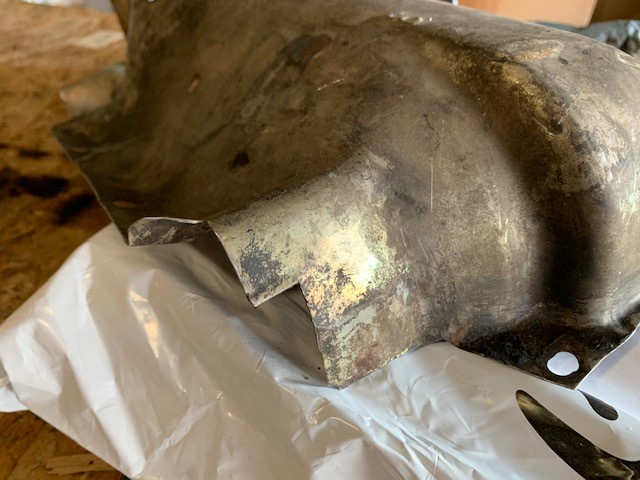
the passenger side 2.0 engine cylinder cover is impossibly hard to find as many have been cut (as yours has) for air conditioning. I applaud you in your job to fix this piece. HOWEVER when it gets this bad, could be easier to convert a 1.7 1.8 piece (readily available) by relocating the two spark plug holes. We are in the process of recreating the right front piece where the accelerator cable passes through. THIS piece is IMPOSSIBLE to find
Like this one?
BTW I have the other side as well but it lost its label.
Posted by: 914sgofast2 Apr 7 2021, 06:52 PM
What I want to know is - what on earth caused those cracks to form in the tins in the first place. That would seem to be a weird place for the tins to work harden and crack up.
Zach
The coil mount area?
It's the engine rocking and vibrating, bending the area till it fails.
It really is huge forces at work here and another example that Porsche/VW never expected these cars to be still around 50 years later.
The coil should be mounted on the fan housing, as well done on the VW Bay Window buses. Post a WTB in the Samba website classifieds for a Bay Window coil mounting bracket and save your tins from cracking in that area again.
Posted by: Bleyseng Apr 7 2021, 08:20 PM
the passenger side 2.0 engine cylinder cover is impossibly hard to find as many have been cut (as yours has) for air conditioning. I applaud you in your job to fix this piece. HOWEVER when it gets this bad, could be easier to convert a 1.7 1.8 piece (readily available) by relocating the two spark plug holes. We are in the process of recreating the right front piece where the accelerator cable passes through. THIS piece is IMPOSSIBLE to find
Like this one?
BTW I have the other side as well but it lost its label.
Gotta kind of wonder if the old tooling for this is lying around the basement at the Karmen factory somewhere, or if it got melted down for some rebar in China.
All the engines were made and assembled in the VW engine plant. They just had one day scheduled to do the 914 engines on the line. All the tin and parts were made by VW
Posted by: Mark Henry Apr 8 2021, 09:32 AM
Hello Mark Henry -
Could you scoot that tin around and show the back inside corner? Mine looks to have been modified but cannot tell for certain. I don't know what it should look like.
Also, does the front outside corner have a captured nut welded on the tin or is it just a straight thru hole?
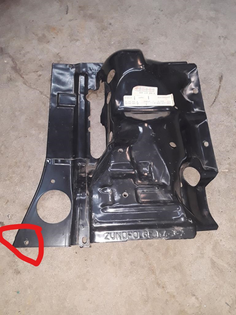
The circled hole has a M6 weldnut.
Not sure where you mean, can you circle the area you want me to take a pic?
Posted by: Shivers Apr 8 2021, 10:05 AM
The dies used to pop these pieces out were quite crude.
That is an understatement.
I had always assumed some of the distortions I've seen in tin were from rough handling and/or engine drops where the tin snagged on the seals.
I never thought about it before but that right front corner piece that is spot welded on looks like it would be pretty easy to reproduce and would make patching tins butchered for AC easier.
That sure would be nice! It is a lot of work to fabricate from scratch and then you are constantly fighting with distortion induced by the welding repair.
I use my air compressor with an air nozzle to cool the metal after each tack when I do sheet metal. Keeps down any distortion, and I do not have to wait as long between.
Posted by: ClayPerrine Apr 8 2021, 11:17 AM
Take a section of copper sheet or copper pipe and beat it flat, then back up the weld area with the copper. You still have to spot weld, but the copper backer stops it from blowing through and doesn't stick to the weld.
Great advice!
Thanks
Thicker copper sheet holds up better but beating copper pipe flat is handy for backing up curved shapes and hàrd to get to areas. The copper has to be pressed against the weld area, if there's a gap it will blow through. The pipe is too thin of a material and will degrade quickly, but I just make another tool.
I have a number of old server CPU heat sinks that are about 1/4 inch thick pure copper with big fins on them. I took them and made some various rounded bits from them. They work great for backing up welding when you don't want it to blow through.
Posted by: seanpaulmc Apr 8 2021, 11:42 AM
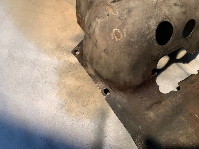
The area of concern I have for this piece of tin is circled here.
On mine it looks and feels like it has been trimmed, but I don't have anything to compare it too. I can't tell if this was just a little snip to make it fit or something more. 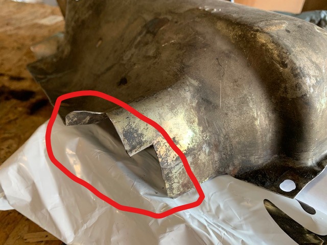
I appreciate all the tips on welding. I've gotten some 1/8" thick copper flat stock. I've made a few weld backers of different sizes. And, I'm using some copper pipe for the curved areas. It's certainly helped!
New question:
How many tins are there for the 2.0 L engine? This is a '73 if that matters.
Thanks!
Posted by: Mark Henry Apr 8 2021, 11:45 AM
The tin is correct in that area, you're good to go.
Posted by: wonkipop Apr 9 2021, 04:09 AM
mate
you are a hero for working out how to do this.
fortunately i do not own one with a coil screwed down on the tins.
which german kook thought that was a good idea?
and those guys are the masters of metal?
(you know the germans have some kind of perverse respect for the brits?)
the japs would never have made that mistake.
thousands of years making swords.
but good old american know how to sort it.
(mind you same know how also screwed the cars, but would be the same here).

Posted by: 930cabman Apr 9 2021, 05:01 AM
mate
you are a hero for working out how to do this.
fortunately i do not own one with a coil screwed down on the tins.
which german kook thought that was a good idea?
and those guys are the masters of metal?
(you know the germans have some kind of perverse respect for the brits?)
the japs would never have made that mistake.
thousands of years making swords.
but good old american know how to sort it.
(mind you same know how also screwed the cars, but would be the same here).
Perhaps $$ caused some German engineer attached the coil to tin. Don't forget, it has worked for many years
Someone needs to gear up and get us new engine tin
Posted by: seanpaulmc Apr 19 2021, 06:41 AM
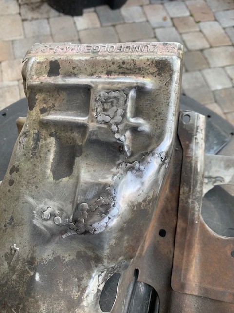
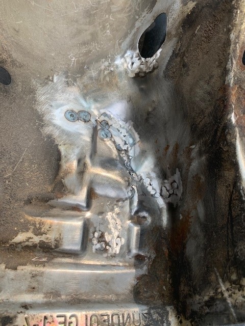
Finally got back to finishing up the tin repair.
Another tin saved, sort of. At least it is better than what I started with and can now be used.
I chased all the cracks to ends.
I welded in patches for the two torn out holes.
I filled all the pin holes (held up to the light to find).
I'm not grinding down further to leave strength in the welded areas and remind me of this when I look back on it in the future.
Best part is I'm learning to weld - first part ever welded.
I appreciate all the advise provided. It's helped a ton. Using a copper weld backer has been crucial to working on the thin metal of the tin. Because of the complex shapes of the tin and where the cracks were I had to make a copper thimble to hold in place while making a spot weld. Worked pretty good. So, here's the pictures... 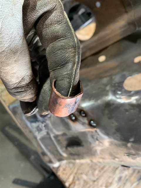
Posted by: seanpaulmc Apr 19 2021, 06:51 AM
When taking the Tin off the engine, I have this small piece on the 3/4 side at the back part of the head. The leading part of the head is where the oil cooler is. Not a very good picture. 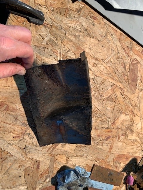
I think this is part 20 in the PET - 022 119 361, air duct /H/R.
Of course this part is missing on the left side of my engine.
I think I need part 21 in the diagram which for the 2.0L is 039 119 362, air duct /H/L.
Would someone confirm the P/N for me?
WTB this part if anyone has extras?
Thanks
Posted by: seanpaulmc Apr 19 2021, 06:57 AM
Are the heat control boxes salvageable? 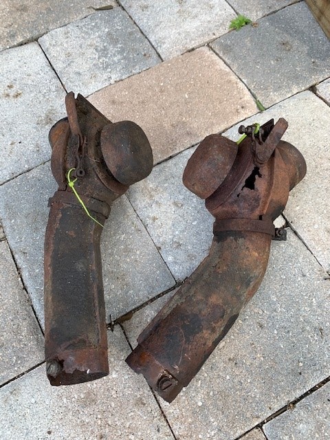
Thanks,
Sean
Posted by: Mark Henry Apr 19 2021, 07:40 AM
Are the heat control boxes salvageable?
Thanks,
Sean
No they look way too crunchy.
The rest of your work looks good

Posted by: 930cabman Apr 20 2021, 07:00 AM
Great job, can I send a couple of mine in for repair?
Posted by: Arno914 Apr 20 2021, 08:37 AM
Any "normal" 914 was long rusted to pieces before the cracks in the engine tin would start to develop. Therefore the "timing" of the factory was right. 
Posted by: seanpaulmc Apr 21 2021, 05:07 PM
Great job, can I send a couple of mine in for repair?
@http://www.914world.com/bbs2/index.php?showuser=24877
At my current rate of progress it will take about 50 years. Can you wait?

Posted by: 930cabman Apr 21 2021, 05:12 PM
Great job, can I send a couple of mine in for repair?
@http://www.914world.com/bbs2/index.php?showuser=24877
At my current rate of progress it will take about 50 years. Can you wait?
I was kidding. I am trying to make one good #3, #4 upper tin from two badly rusted pieces. Keep up the good work, do you have a build thread going here?
Posted by: seanpaulmc Apr 21 2021, 05:19 PM
Moving onto the other side...
This is the main top tin for the 1-2 side. 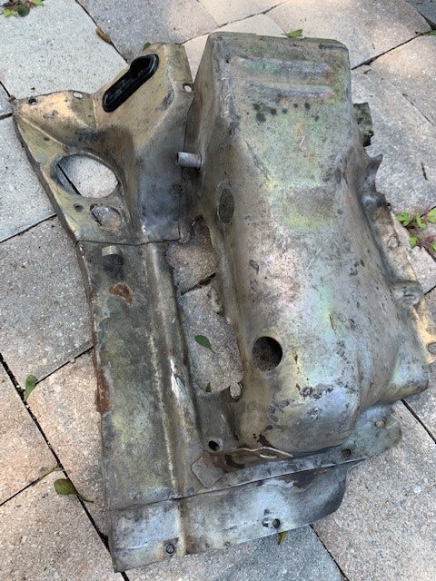
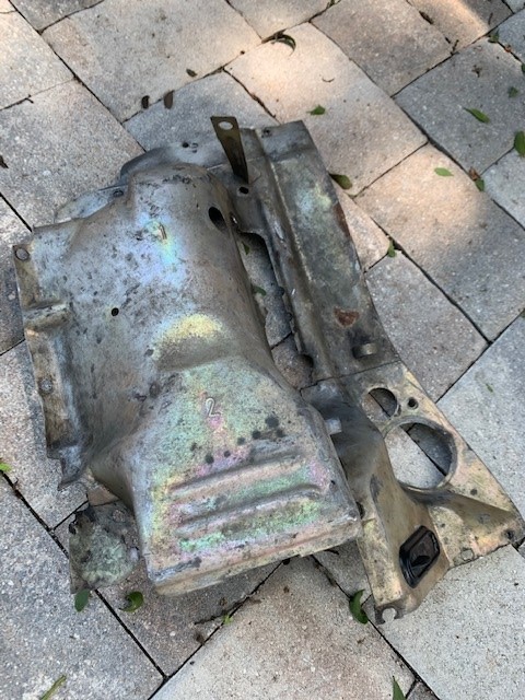
It's in better shape than the 3-4 side however it's been customized to fit from the obvious deformations. It will also need some small weld repairs.
Now my questions:
1. Is this the correct tin for a 2.0L engine?
2. What is the tube coming off the side next to the #2 cylinder?
3. What is the bracket for at the back by the #1 cylinder?
4. In the side view, should it curve down like this or is this "customized"?
Just want to reiterate that I appreciate the feedback. It's been pivotal in getting the other side welded up and ready to be put back in service.
Thank you!
Posted by: seanpaulmc Apr 23 2021, 11:39 AM
Bump for questions about the 1-2 tin.
How much do I need to worry about trying to straighten out this 1-2 side of the Tin?
Seems reasonable to do but I don't know if it should have any curve to it or not.
Thanks,
Posted by: dirk2056 May 8 2021, 10:52 AM
Can someone post pictures of what profile the tins are design to look? I assume they are not flat profile?
Posted by: 930cabman May 8 2021, 03:33 PM
Moving onto the other side...
This is the main top tin for the 1-2 side.
It's in better shape than the 3-4 side however it's been customized to fit from the obvious deformations. It will also need some small weld repairs.
Now my questions:
1. Is this the correct tin for a 2.0L engine?
2. What is the tube coming off the side next to the #2 cylinder?
3. What is the bracket for at the back by the #1 cylinder?
4. In the side view, should it curve down like this or is this "customized"?
Just want to reiterate that I appreciate the feedback. It's been pivotal in getting the other side welded up and ready to be put back in service.
Thank you!
Q #1: I would say yes this would be a 2.0 #1, #2 top tin. The spark plug holes appear to be in the correct locations. 1.7 and 1.8 liter motors have the spark plug holes higher up on the tin.
Q #2: I cannot help with this one
Q #3: Bracket is for mounting the pressure regulator
Q #4: From what I can tell the tin is bent, the correct plane should be apparent when you fit the rear (from side to side) tin.
Posted by: 76-914 May 8 2021, 04:26 PM
Take a section of copper sheet or copper pipe and beat it flat, then back up the weld area with the copper. You still have to spot weld, but the copper backer stops it from blowing through and doesn't stick to the weld.
Great advice!
Thanks
Thicker copper sheet holds up better but beating copper pipe flat is handy for backing up curved shapes and hàrd to get to areas. The copper has to be pressed against the weld area, if there's a gap it will blow through. The pipe is too thin of a material and will degrade quickly, but I just make another tool.
Mark, your probably using tube that is type M. That is a thin residential grade and is easily identified by the RED lettering. FWIW, type K is the thickest for industrial use and has Green lettering. Type DWV, used for drains, waste & vents, is the very thinnest and has Yellow lettering. Use either type L tube, which has Blue lettering, or use a copper fitting which will have the wall thickness of type L. Your will be able to more easily bend your copper backing plate if you anneal it. Copper stiffens over time and will need annealing occasionally.
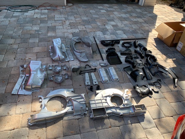
Posted by: seanpaulmc May 8 2022, 05:18 PM
I truly appreciate all the tips and support on welding that were provided. The suggestions and links helped me a lot and I'm happy with how the tins came out for a very first time welding effort.
To finished this one out, here are the Tins back from powder coating...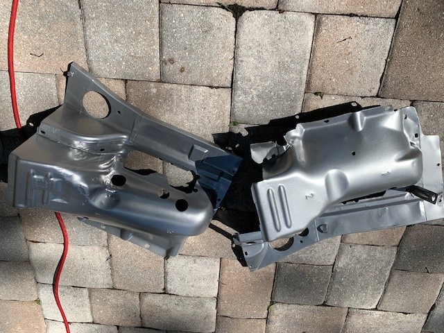
Thanks and 
Posted by: Mark Henry May 8 2022, 05:48 PM
I truly appreciate all the tips and support on welding that were provided. The suggestions and links helped me a lot and I'm happy with how the tins came out for a very first time welding effort.
To finished this one out, here are the Tins back from powder coating...
Thanks and
Good job, I just did all that... X8 sets.
Powered by Invision Power Board (http://www.invisionboard.com)
© Invision Power Services (http://www.invisionpower.com)