Printable Version of Topic
Click here to view this topic in its original format
914World.com _ 914World Garage _ My latest challenge. Here we go again.
Posted by: rmarx Apr 3 2021, 11:09 PM
It had been about eleven years since my last 914 build. It was shown on the cover of the January 2010 Retro Cars Magazine. It was a 72 with a 327 Chev small block, GT flares , 5 lug conversion and a long list of modifications. I have spent the last eleven years building , restoring , highly modifying two separate 912s. One was converted from a short to long wheelbase RSR, the other was a 69 912 converted to an R Gruppe style 911. I have owned about eight 914s over the years and I always seem to be drawn back to their mid-engined targa topped allure.
About a year and a half ago, I obtained a 72 roller from fellow 914 world enthusiast Brian Adkins. He was nice enough to give me a good dal on the car, so it was time to begin my next crazy idea.
I am installing a 2004 Subaru EZ30R engine with an 04 WRX transmission converted from four to two wheel drive. The trans is very strong and able to handle all the power I want to throw at it. It will have a hydraulic clutch and operated by a Cable system.
The engine will be operated with an ECU Master computer. The power output should be in the 280-300 hp range per the experts that use these motors in sand rail conversions.
The car initially received a 1.7 four generously donated by Chris Baker (Tyga Boy). I got the car running well enough to participate in last year's West Coast Rally. I actually won an award for Best Patina ( Best Shit Box) . I have since pulled the motor and trans, stripped the paint, collected most of the parts needed for the conversion and will install the new drivetrain very soon.
It is my intention to show many pictures and details of the process.
Many thanks to to all those that have in the past and in the future helped me to achieve my goals for this project. I couldn't do it without hem.[attachmentid=788074] [attachmentid=788074]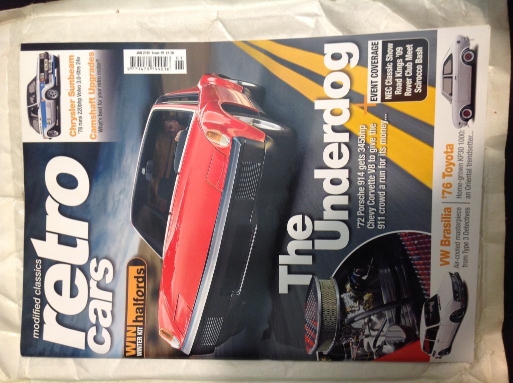
Posted by: tygaboy Apr 4 2021, 08:15 AM
Hey Bob - A couple things:

We don't want promises of pics... we want actual pics! 
Best of luck with this latest build. Let me know if there's anything I can do to help.


Posted by: willieg Apr 4 2021, 08:46 AM
Bob. I agree with Chris. Let’s see some pictures of that engine.
Posted by: 76-914 Apr 4 2021, 05:14 PM
Good choice. That R series is easy to flip the intake 180 and avoid cutting the trunk since it is DBW. Looking forward to another Suby conversion. And what Chris said. Post pic's or it didn't really happen. 
Posted by: Mayne Apr 4 2021, 07:33 PM
Sounds exciting! I’ll be looking forward to what I hope is an excessively detailed build!
I loved Retro Cars! My brother used to contribute content and I wish it was still around.
Posted by: rmarx Apr 5 2021, 02:13 PM
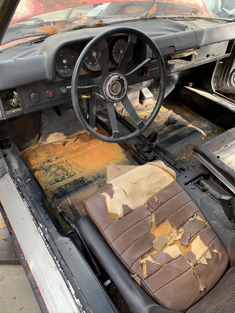
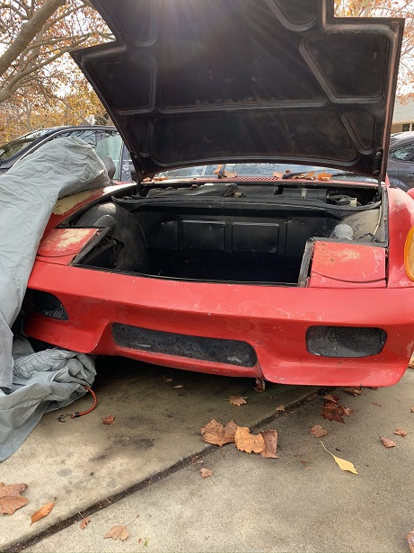
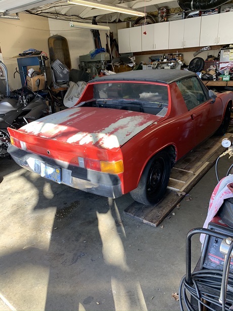
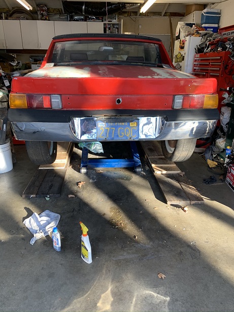
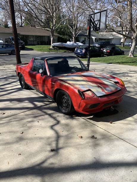
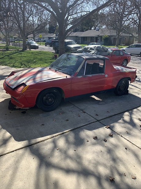
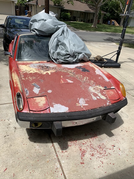
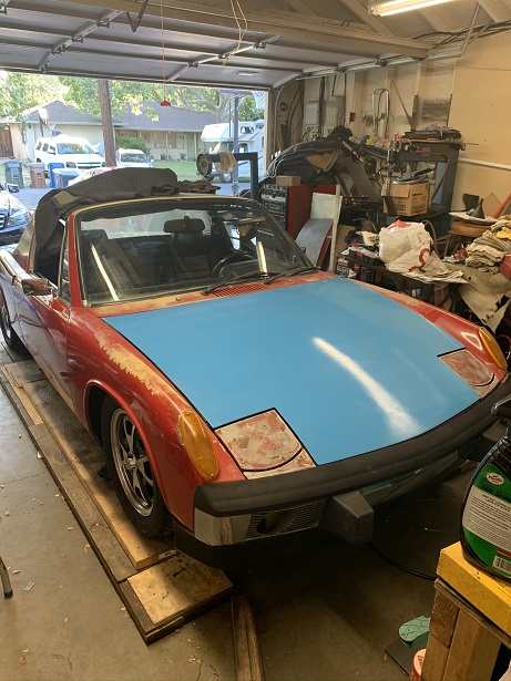
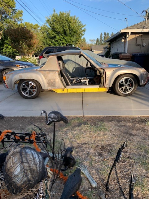
Here is the car as I first saw it. It has a 2.0 ltr motor with a side shifter trans and 4 bolt Fuchs. None of those things will be with the car when iI obtain it.[attachmentid=788194]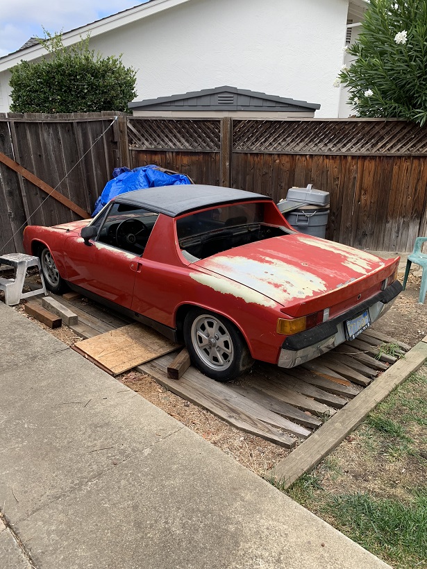
Posted by: rmarx Apr 6 2021, 12:40 PM
More pics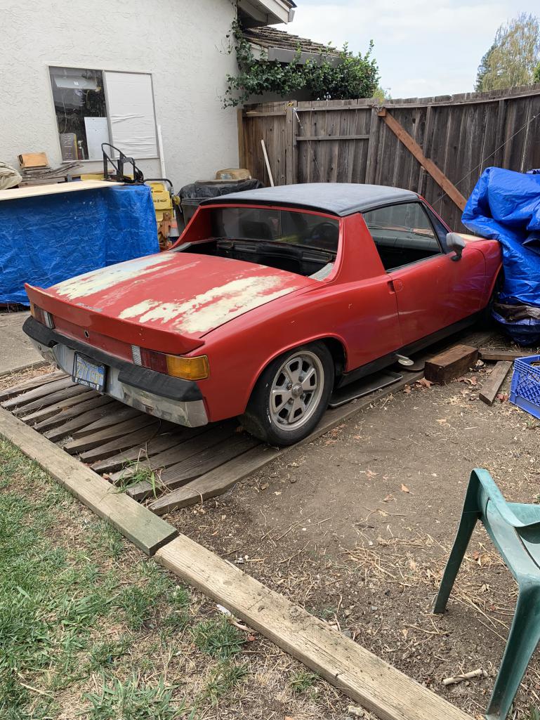
Attached image(s)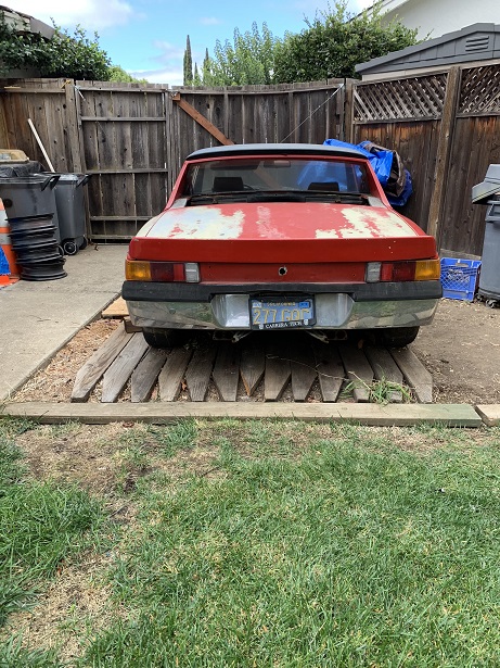
Posted by: rmarx Apr 6 2021, 12:59 PM
more pics
Attached image(s)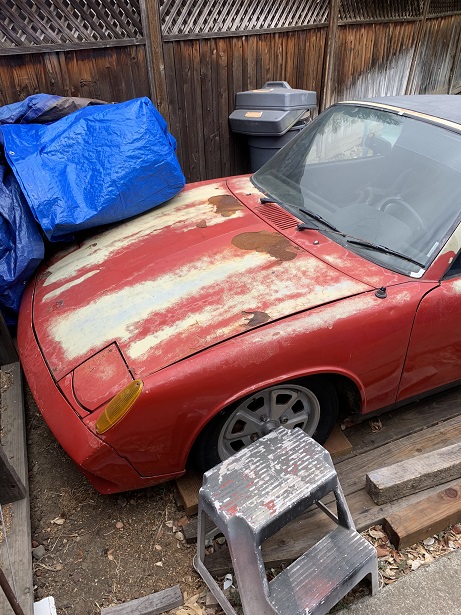
Posted by: rmarx Apr 6 2021, 05:26 PM
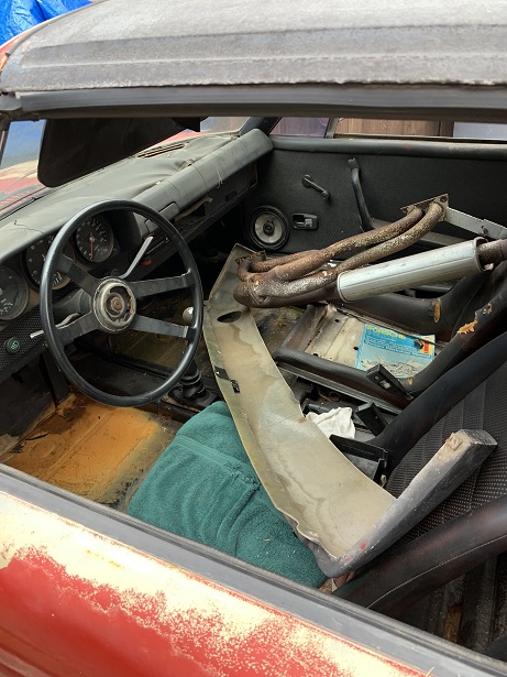
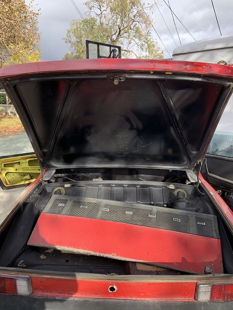
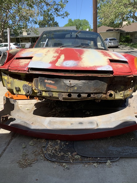
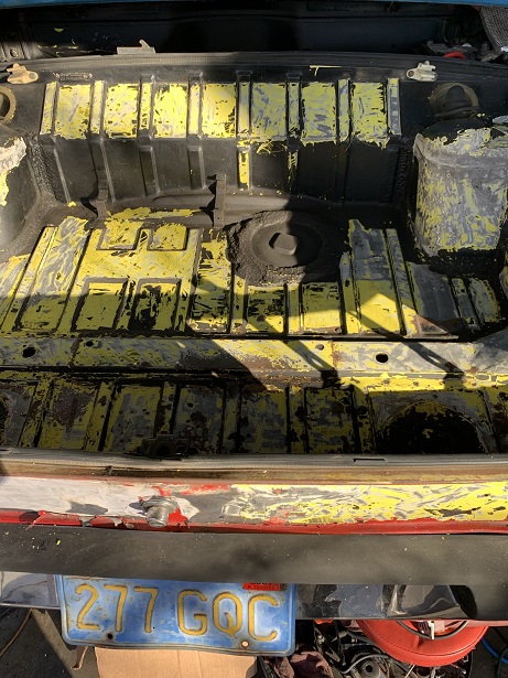
You want pictures? I got pictures. Here are more pictures showing all the details that will have to addressed in the restoration/modification of this car.
Attached image(s)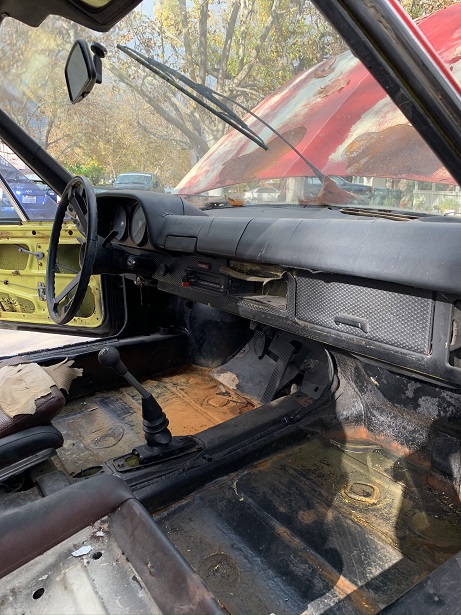
Posted by: rmarx Apr 7 2021, 11:13 AM
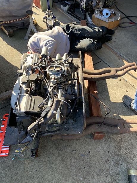
I brought the car home and began to clean and inspect what actually needs to be done, (everything). I picked up a 901 side shifter and 1.7 ltr. motor from Chris @http://www.914world.com/bbs2/index.php?showuser=19241 .
The next posts will show the process of obtaining all the missing parts, installing and getting the car to run under it's own power.
Attached image(s)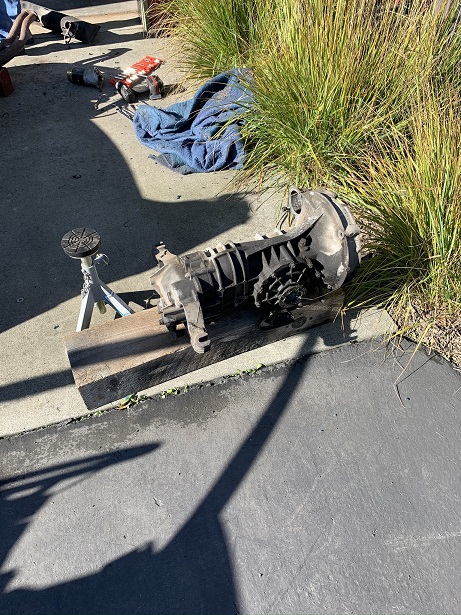
Posted by: Mueller Apr 7 2021, 02:36 PM
Looks like a great start. I like all that room you have on the side of your house for the car.
Posted by: Mayne Apr 7 2021, 03:12 PM
Looking good! I spy a 968...
Posted by: rmarx Apr 7 2021, 05:00 PM

Looking good! I spy a 968...
Yes you do.
Posted by: rmarx Apr 8 2021, 10:51 AM
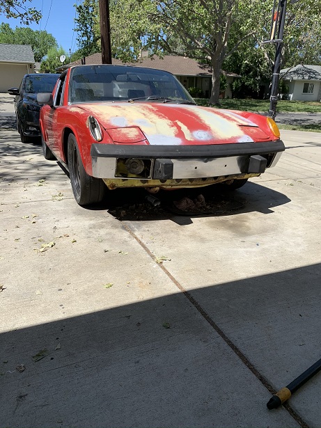
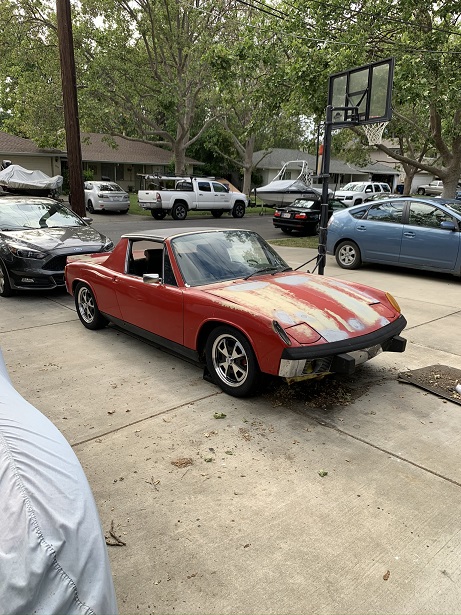
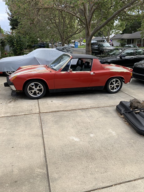
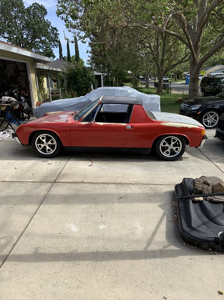
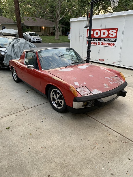
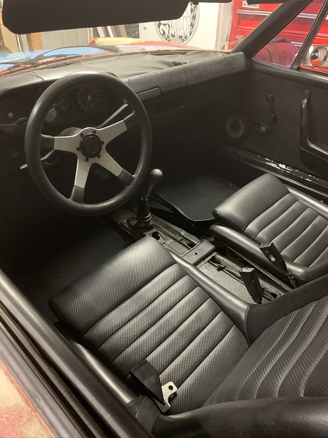
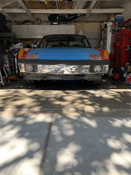
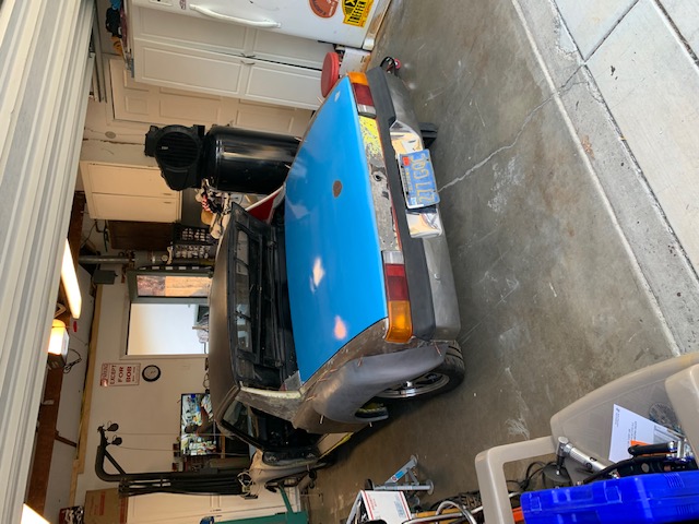
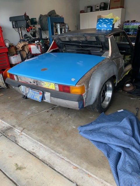
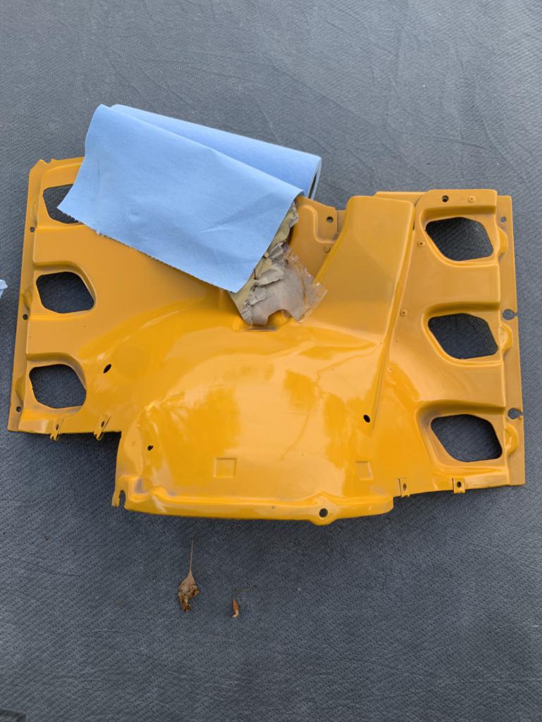
The upgrade process begins. The seats were replaced with nicer units obtained from Chris@Tigaboy. The 916 front bumper was removed and replaced with a Chrome 73 unit I had in storage and the wheels and tires were replaced with EMPI replica Fuchs along with 205/50/15 RE71R tires.
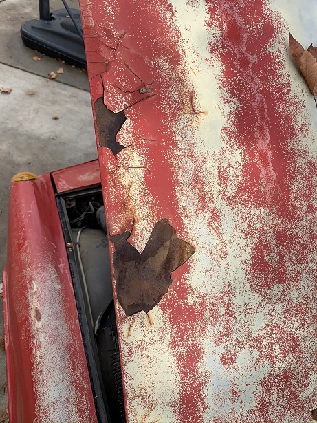
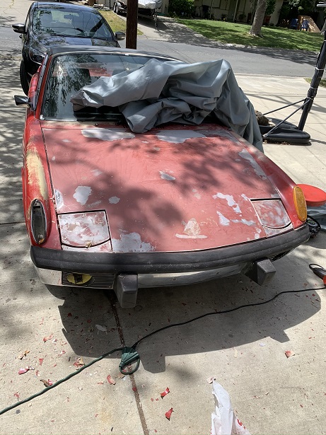
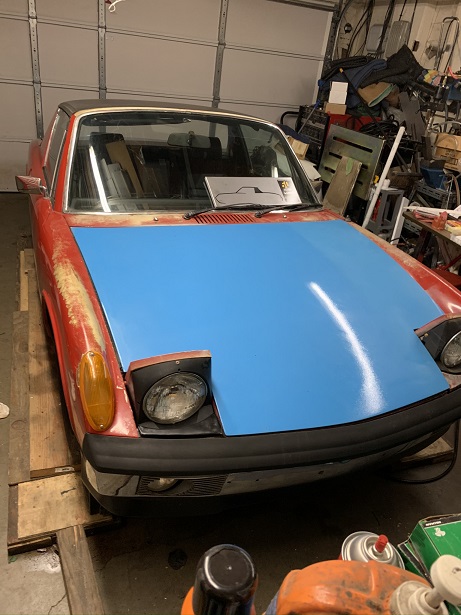
The hood was stripped of all the cracked paint.
Attached image(s)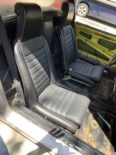
Posted by: rmarx Apr 9 2021, 10:34 AM
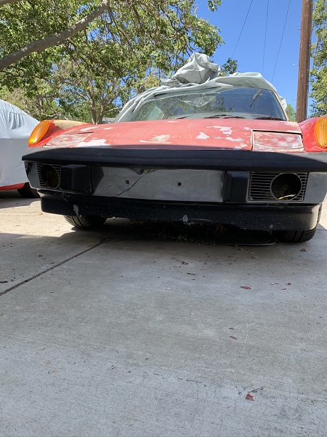
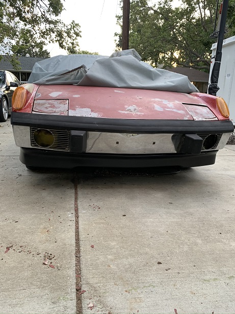
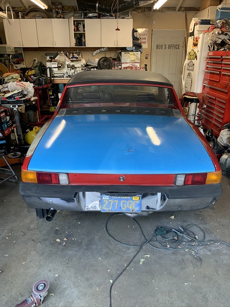
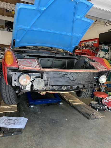
The restoration continues. I changed the front bumper, added a spoiler. there is a before and after picture showing the initial installation and one with it repaired and painted. I changed the steering wheel, once again donated by Chris @ tygaboy. I installed new carpet floor mats. I removed the front bumper and painted the body black to freshen it up. There are before and after pictures of the car in it's then current state, then I changed the front and rear hoods for ones that were in better condition, (less rust). I also removed the rear spoiler to give a little cleaner look.
Attached image(s)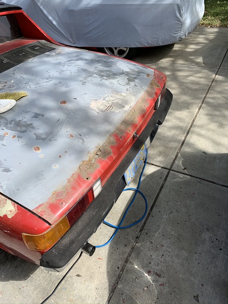
Posted by: rmarx Apr 11 2021, 05:10 PM
Good choice. That R series is easy to flip the intake 180 and avoid cutting the trunk since it is DBW. Looking forward to another Suby conversion. And what Chris said. Post pic's or it didn't really happen.
I flipped the intake manifold, but it interferes with the alternator. I will have to cut the car.
Posted by: 76-914 Apr 11 2021, 06:09 PM
Are you running the alt in the stock location?
Posted by: rmarx Apr 12 2021, 04:50 PM
Yes
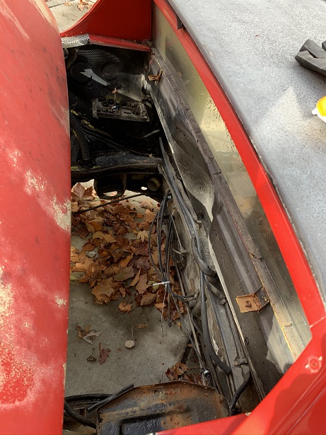
Posted by: rmarx Apr 12 2021, 05:18 PM
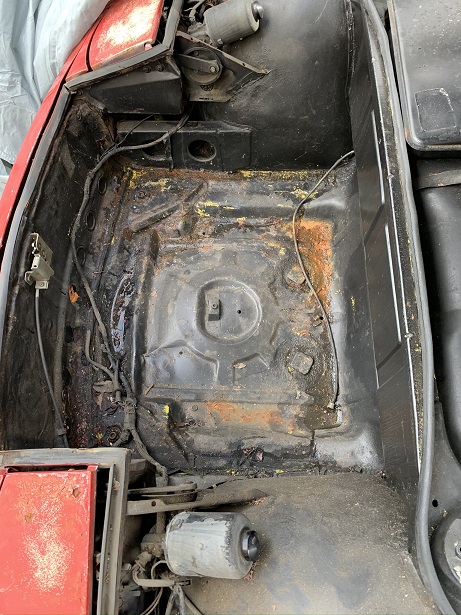
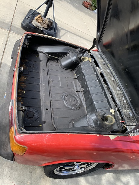
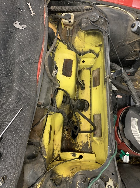
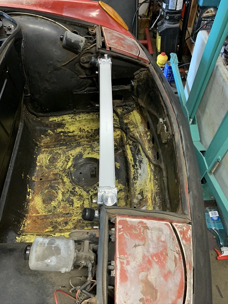
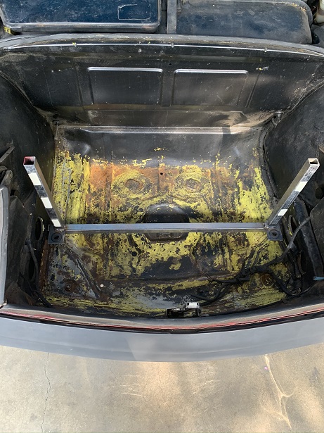
Removed the gas tank to replace the fuel lines. A couple before and after pictures of the the area cleaned up.
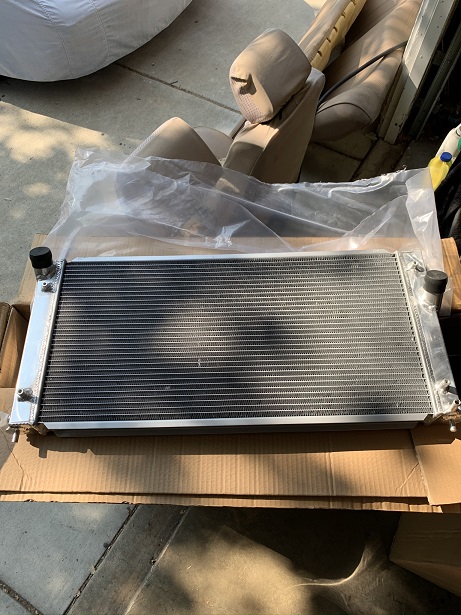
The CONVERSION begins!
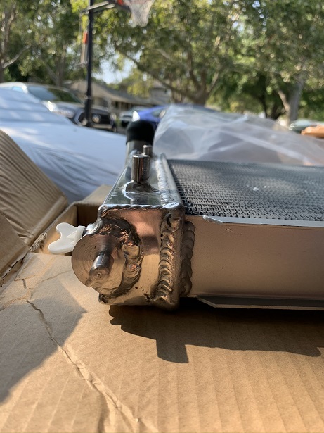
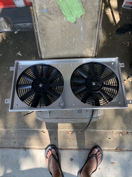
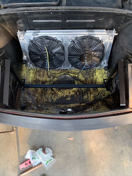
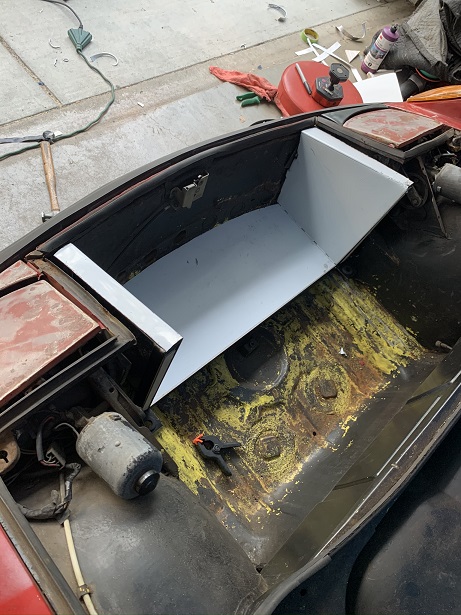
Pictures of the new radiator and it's fan housing as it fits in the car. It's a nice pice. It was originally made for a Celica.
Attached image(s)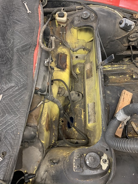
Posted by: Mayne Apr 12 2021, 07:58 PM
Looks good. What are the dimensions of the radiator?
Posted by: rmarx Apr 13 2021, 10:29 AM
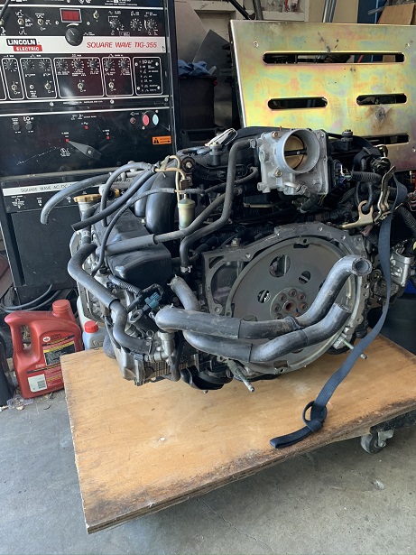
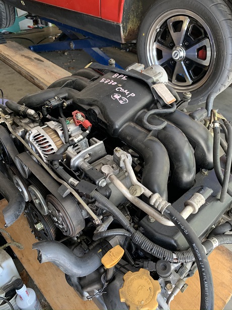
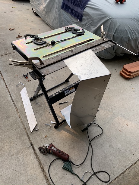
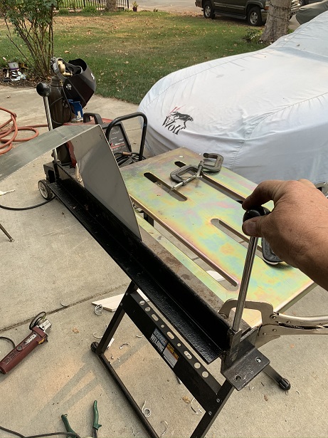
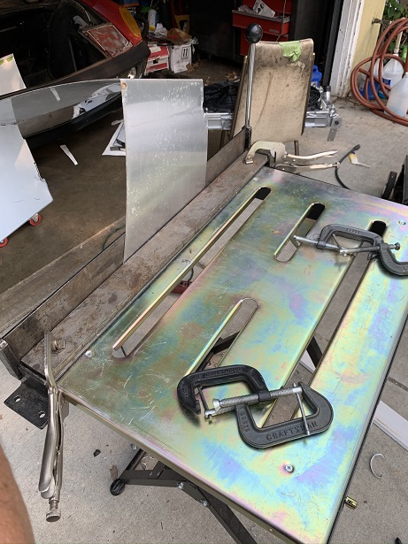
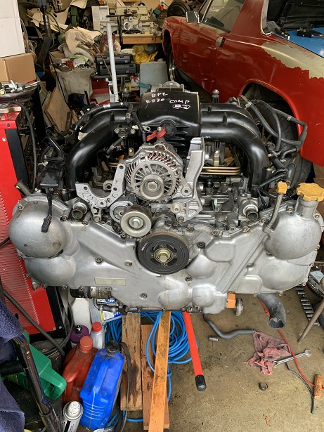
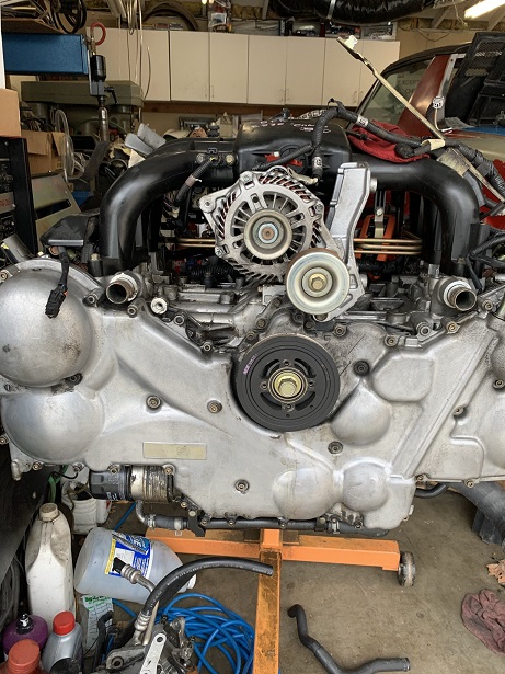
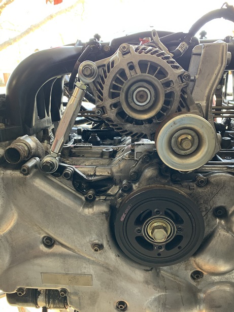
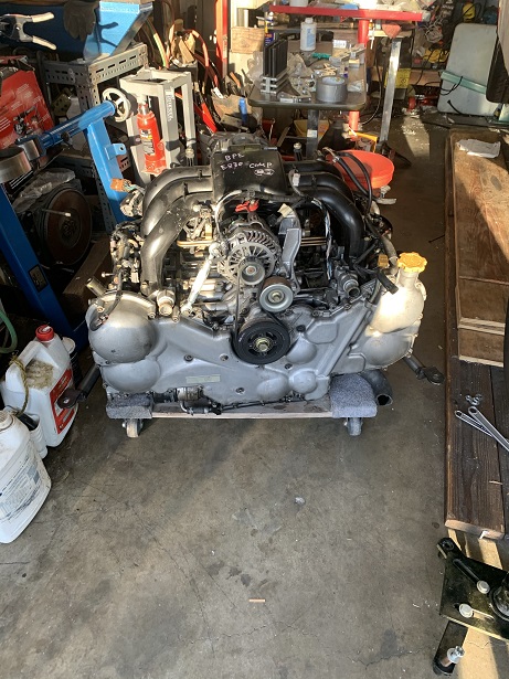
Where's the beef? It's right here. Subaru EZ30R. 4 cam, variable cam on the intake, fly by wire throttle, individual exhaust ports for each cylinder as opposed to the one oval exhaust port on earlier motors. It should make about 280-300hp with the headers and stand alone management system.
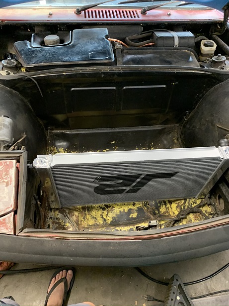
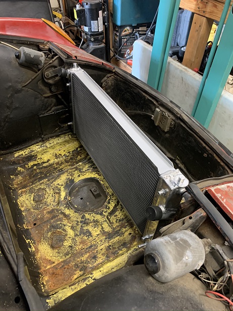
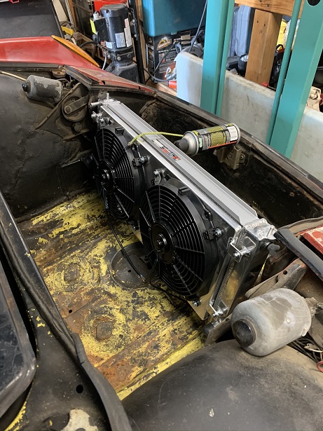
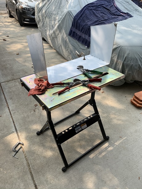
Pictures of the radiator being mounted in the car. A few pictures of the shroud being made with my brake.
Attached image(s)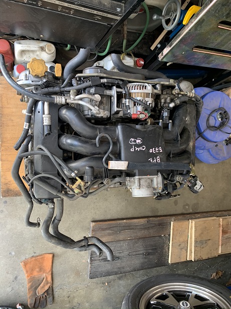
Posted by: 76-914 Apr 13 2021, 11:17 AM
Yes
Well that's that. If you aren't planning on AC you can 86 the comp & PS pump and relo the alt to center of engine (as others have done) thus allowing you to flip the intake. I like your approach to making the shroud. Good choice on the radiator. Did you need to purchase the fans separately of was it a package deal? Also, when you get to it post up the ECU and map you will be using.
Posted by: rmarx Apr 13 2021, 12:34 PM
Yes
Well that's that. If you aren't planning on AC you can 86 the comp & PS pump and relo the alt to center of engine (as others have done) thus allowing you to flip the intake. I like your approach to making the shroud. Good choice on the radiator. Did you need to purchase the fans separately of was it a package deal? Also, when you get to it post up the ECU and map you will be using.
The alt is already at the center. A future post will reveal. The fans came with the radiator.
I will be using ECU Master for the ECU. They seem to be set up for the vario cam and fly by wire throttle, and it's more affordable than some of the other products out there.
Posted by: rmarx Apr 14 2021, 10:44 AM
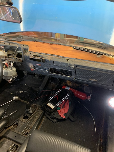
I remove the dash pad and replaced the worn dash top with new material. A couple pictures of the car attending the WCR. It actually won an award for best patina. One picture shows the addition of a plastic dash top cover. Not the best solution, but it will do for now.
Attached image(s)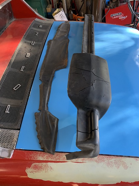
Posted by: Wyvern Apr 14 2021, 03:25 PM
Looking great Bob.
Still I like the red patina trunk and fronk ... you paid for that . LOL
Posted by: 76-914 Apr 14 2021, 07:56 PM
I didn't see the 3.0 or 3.6 in their Base Maps section. Hopefully you'll provide more info for us Pilgrams as your build progresses. BTW, I'd never heard of them before. Thx for that info.
Posted by: rmarx Apr 15 2021, 05:42 PM
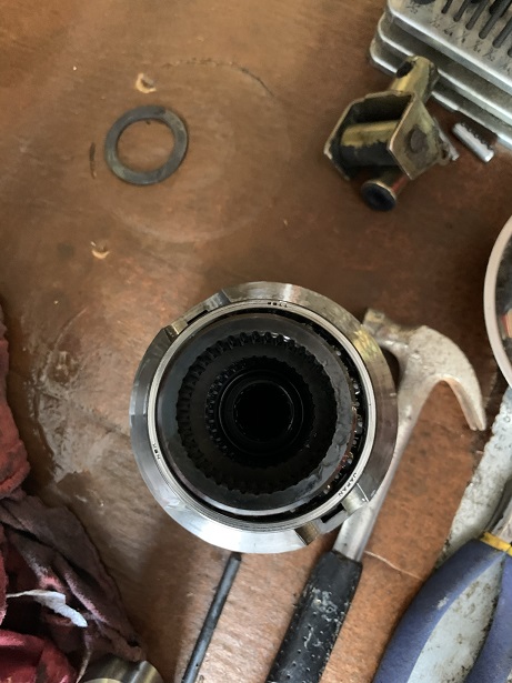
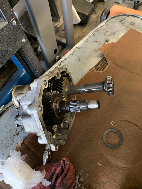
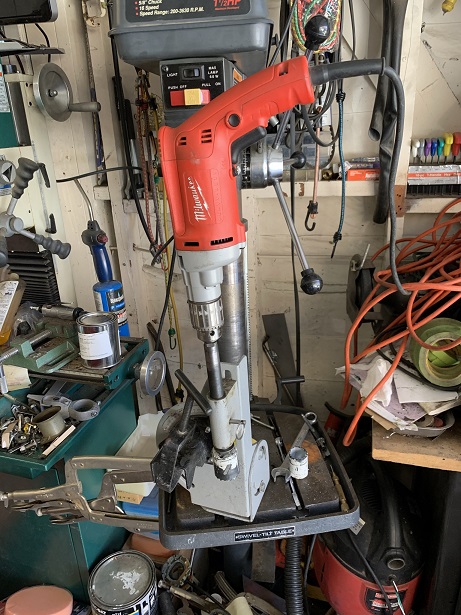
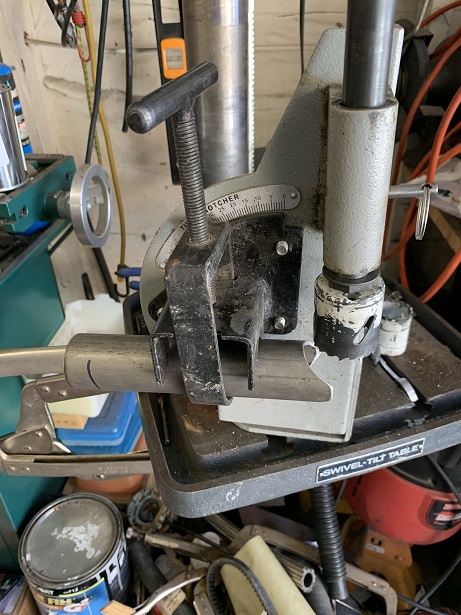
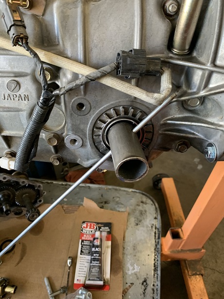
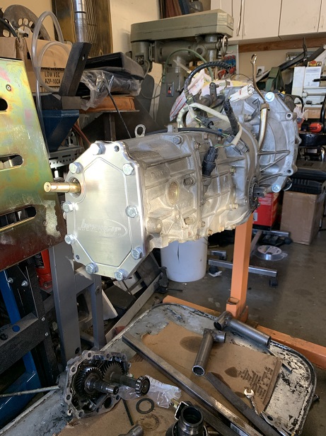
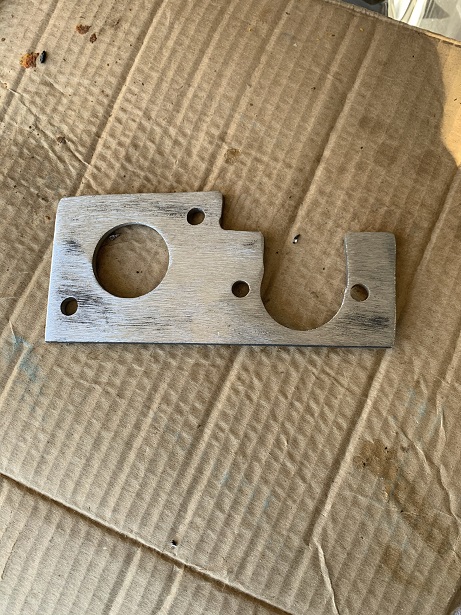
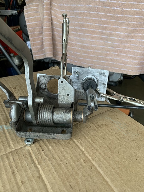
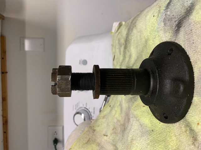
Here are pictures of the transmission I will be using. It is a 04 WRX 5speed. I had to fabricate a tool to lock the two shafts together so that I could remove an inner shaft bolt. I am missing the picture of the completed tool. What I did was cut two pieces of roll bar tubing, drilled holes in each piece to accommodate a rod that would hold it to the shaft. I used my tubing notcher to notch one end of each tube that would be welded to another piece of tubing that connects the two together. Pictures show the inner guts (shafts and gears) that were removed when converting the trans from four to two wheel drive. The final pictures show the new end plate that replaces the stock nose cone. If save about 5-6 inches in overall length of the trans while saving weight at the same time.
Attached image(s)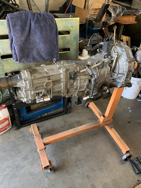
Posted by: Mayne Apr 15 2021, 06:43 PM
Probably a stupid question, but what is the shaft that comes through the new cover plate? And does it have a purpose or just kind of hang out?
Posted by: mgp4591 Apr 15 2021, 08:24 PM
Probably a stupid question, but what is the shaft that comes through the new cover plate? And does it have a purpose or just kind of hang out?
Not a stupid question at all...it's the shifter shaft that will be connected to the cable shifting mechanism.
Posted by: rmarx Apr 15 2021, 09:19 PM
Probably a stupid question, but what is the shaft that comes through the new cover plate? And does it have a purpose or just kind of hang out?
Not a stupid question at all...it's the shifter shaft that will be connected to the cable shifting mechanism.
That is correct. Thank you.
Posted by: rmarx Apr 16 2021, 10:40 AM
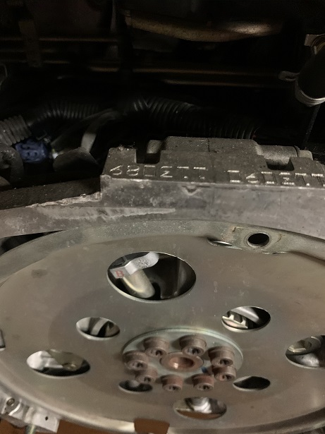
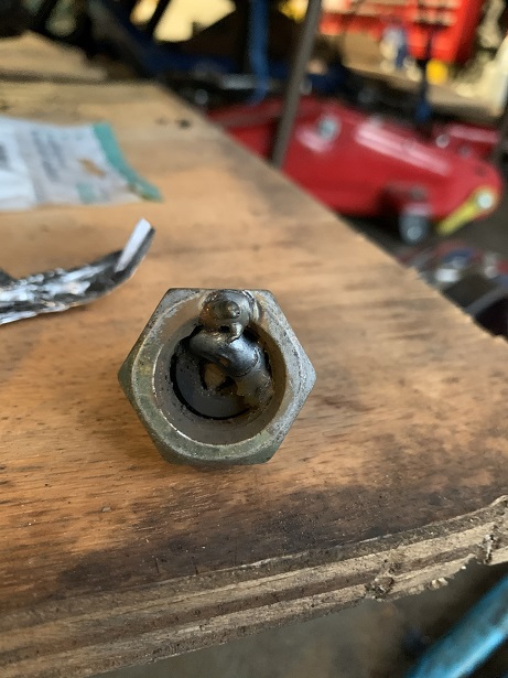
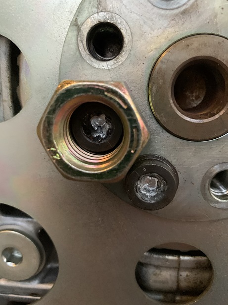
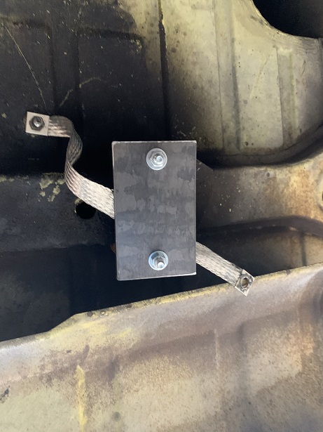
One thing I noticed about these Subaru motors is that all the bolts are on there really tight. Case in point, while removing the flywheel bolts, I had to use all my strength to break them loose. I got the first five to loosen up, the the remaining three would not budge. They are a female torx type bolt. I snapped the tool in half while trying to loosen them up and ended up stripping them all. Thats when that sinking feeling starts to creep in knowing that it could be a really expensive solution to getting the remaining bolts off the crankshaft. I tried vise grips, thread extractors and heat all to no avail.
The heads of the flywheel bolts are round and smooth and it's hard to get a good angle to grip them.
Then I got an idea...
I went to the hardware store and bought some nuts with an internal diameter of the exterior diameter of the bolt head. I slid them over the bolt head and welded the nut to the bolt head. I then bought a new socket to match the nut diameter and proceeded to attempt to remove the stuck bolt.
It came out like butter.
I posted my solution to help anyone who might find themselves in a similar hopeless situation.
Attached image(s)
Posted by: CptTripps Apr 16 2021, 04:54 PM
What a great idea, and I'm shocked nobody thought to do that before. I ended up cutting into one of mine once, and using a big flat-head screwdriver...cut and attached to a socket...attached to an impact driver.
Seems so obvious now.
Well done!
Posted by: rmarx Apr 19 2021, 10:57 AM
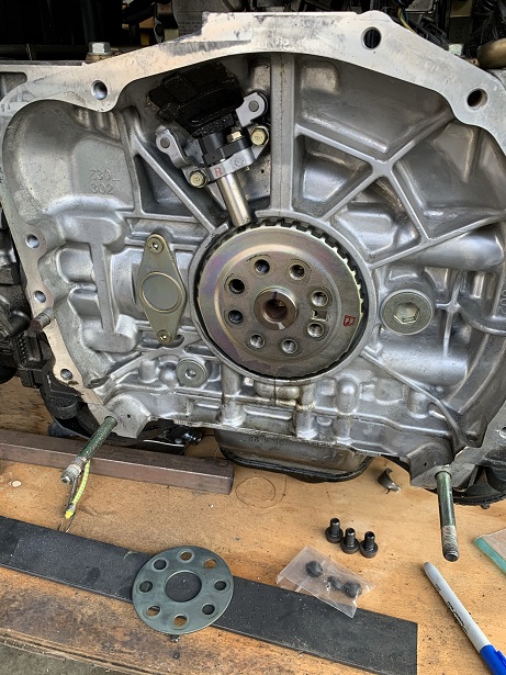
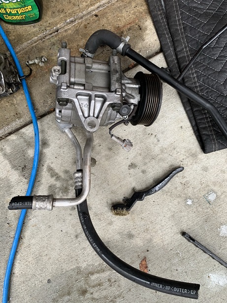
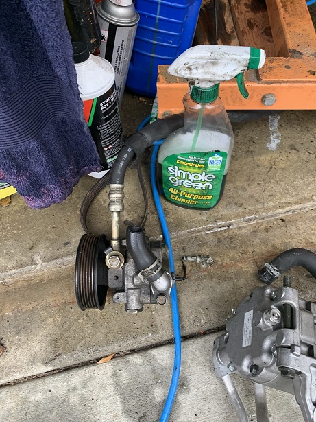
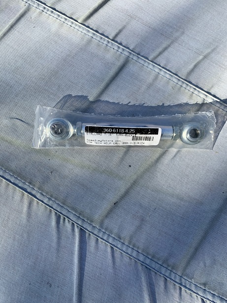
I started to make some plates for the trans cradle mount. A picture of them mounted. I installed the flywheel and started to unclutter the engine by removing the power steering pump and the AC compressor. I obtained and installed a nice aluminum turnbuckle to adjust the belt for the alternator.
Attached image(s)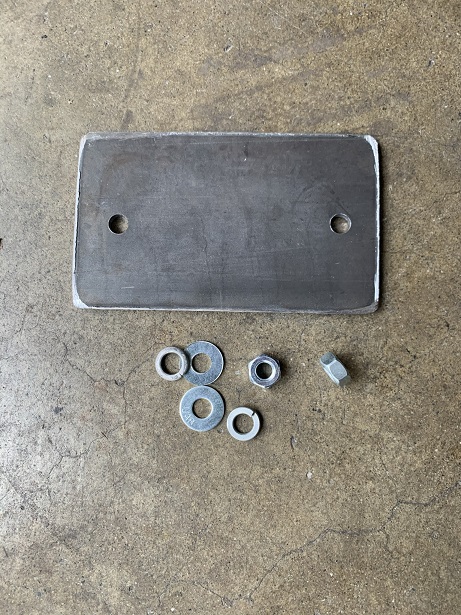
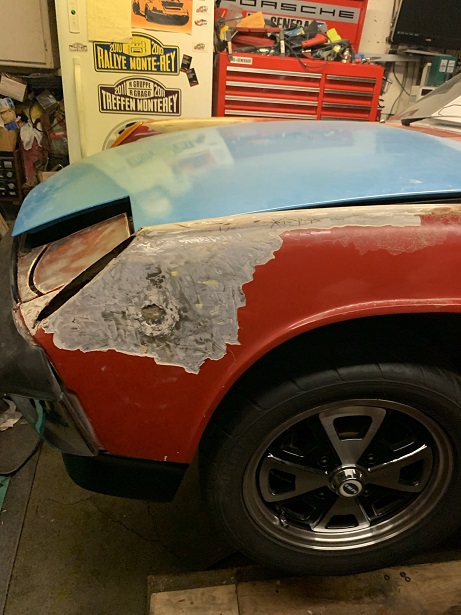
Posted by: rmarx Apr 20 2021, 10:40 AM
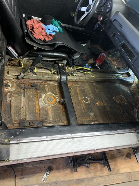
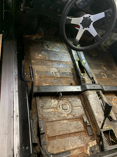
I was getting a little bored and decided to look into a small rust spot around the left front turn signal lens. I got out my heat gun and single edge razor blade holder and began to remove the paint surrounding the lens. What I found was that it really not the serious and easily repairable. The only problem was I couldn't stop myself and began to strip the entire car of it's "patina". Sometimes I get a little obsessive. I just can't help myself. I stripped the whole body, the front and rear trunks and the interior.
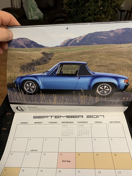
I found a picture of a car color I liked in a 2017 914 calendar. Does anyone know what color that is?
Attached image(s)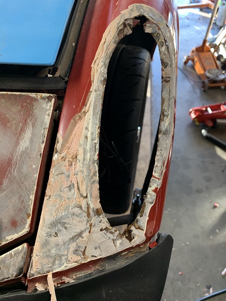
Posted by: mgp4591 Apr 20 2021, 11:59 AM
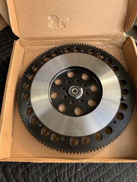
Which flywheel did you go with?
Posted by: rmarx Apr 20 2021, 12:33 PM
Which flywheel did you go with?
I don't remember. I got it from EBAY as a complete package. Flywheel, clutch, bearing, etc.
I will look to see if I still have the box. If so, I will post.
Posted by: mepstein Apr 20 2021, 12:43 PM
Rob's car maybe? ABM - Alaska blue metallic
http://www.914world.com/bbs2/index.php?showtopic=352836
@http://www.914world.com/bbs2/index.php?showuser=7784
Posted by: billh1963 Apr 21 2021, 06:54 AM
Rob's car maybe? ABM - Alaska blue metallic
http://www.914world.com/bbs2/index.php?showtopic=352836
@http://www.914world.com/bbs2/index.php?showuser=7784
Yep...looks like Alaska Blue to me, too.
Posted by: rmarx Apr 21 2021, 10:48 AM
Rob's car maybe? ABM - Alaska blue metallic
http://www.914world.com/bbs2/index.php?showtopic=352836
@http://www.914world.com/bbs2/index.php?showuser=7784
Thank you for the reply. I love that color!
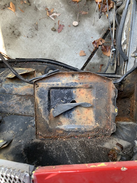
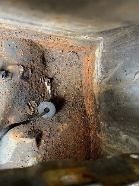
Posted by: rmarx Apr 21 2021, 11:05 AM
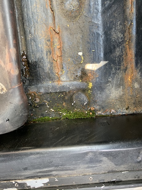
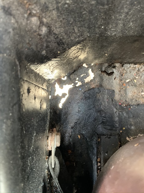
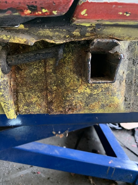
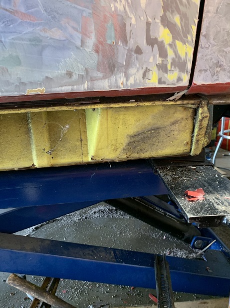
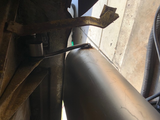
I removed the rockers to see what surprises lay ahead for me. I was happily surprised to find that they are both in great shape. The only repair needed will be to reweld the top of the jack receiver tube. After cleaning them up, they look quite good. I have been noticing a fuel smell every once in awhile. The picture shows the hose disconnected from the the tube. Perhaps that was the culprit. Very happy.
Attached image(s)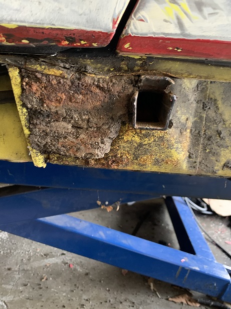
Posted by: rmarx Apr 22 2021, 10:51 AM
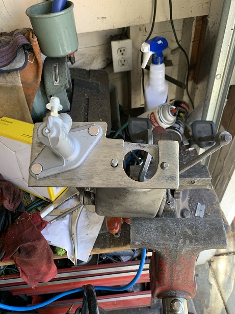
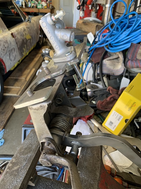
Todays post is showing the pedal box conversion from cable to hydraulic. This design was inspired from a post by Kent @http://www.914world.com/bbs2/index.php?showuser=9964 . I basically copied his design for the bracket, but I came up with a different design for the connection between the pedal lever and the clutch master cylinder. The master cylinder is a unit from a Honda Civic.
Attached image(s)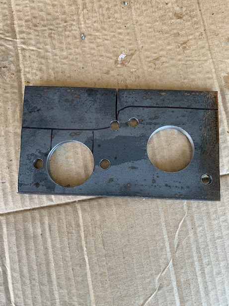
Posted by: 76-914 Apr 22 2021, 11:07 AM
Todays post is showing the pedal box conversion from cable to hydraulic. This design was inspired from a post by Kent @http://www.914world.com/bbs2/index.php?showuser=9964 . I basically copied his design for the bracket, but I came up with a different design for the connection between the pedal lever and the clutch master cylinder. The master cylinder is a unit from a Honda Civic.
I like it. There is always room for improvement.
Posted by: rmarx Apr 23 2021, 12:55 PM
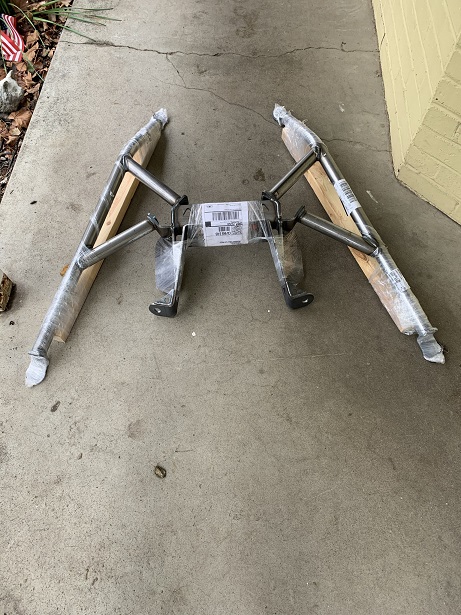
I received a engine and transmission cradle from Coldwater. The following pictures show the cradle as I received it, unwrapped and mount in the car. I even showed it mounted to the engine. This is a very nice piece. The welds are better than I can produce and the quality is quite good.
There is a fitment issue with my particular engine and header of choice. Rather than modify this nicely put together piece, I am going to go another direction. Ian is working on another design to accommodate my specific needs. Therefore, this cradle is now available. I live in the northern California bay area. If anyone is interested in it and not wanting to wait for one to be built by Coldwater, mine is now available.
Attached image(s)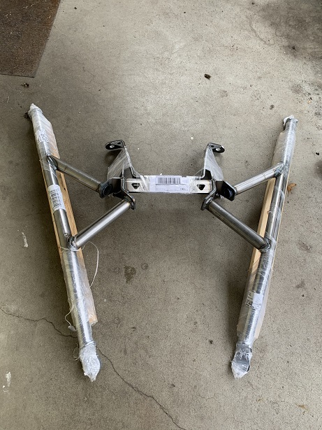
Posted by: Mayne Apr 24 2021, 07:18 AM
Those cradles look awesome. Is the engine cradle not well suited for an EZ30R engine, or does is it have to do more with your header choice? I thought it was designed to work with a variety of Subaru engines, including the EZ30.
Posted by: rmarx Apr 26 2021, 11:08 AM
Those cradles look awesome. Is the engine cradle not well suited for an EZ30R engine, or does is it have to do more with your header choice? I thought it was designed to work with a variety of Subaru engines, including the EZ30.
It has to do with my header choice.
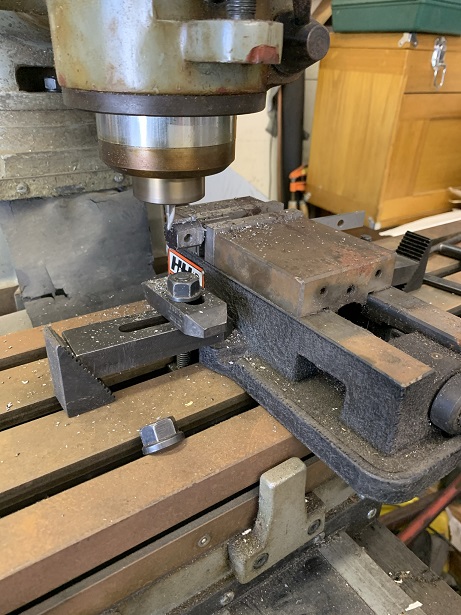
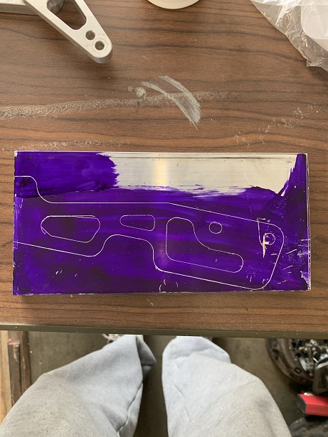
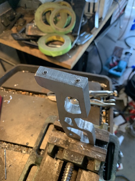
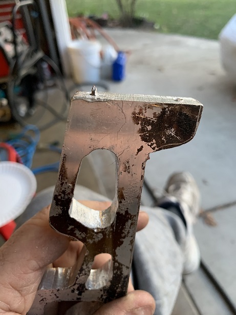
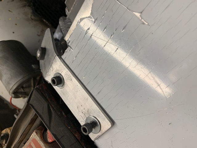
Posted by: rmarx Apr 26 2021, 12:14 PM
I started to build some bracketry for the cable shift mechanism that would mount to the transmission. The material I obtained is 6063 aluminum. I experienced some difficulty in drilling this material. While drilling, the bits would seize in the material and ultimately snap. Previously, I have never had any problems drilling aluminum, so this was becoming frustrating. What I ultimately found out was that even though I didn't think that spindle speed and lubrication would matter that much, it does. I calculated the the spindle speed by taking the cutting speed of aluminum, times it by four and dividing the result by the diameter of the drill bit. The end result was that I needed to speed up the spindle speed considerably. I did that and added some cutting oil for insurance. The end result was much more successful. I've posted a few pictures of the first bracket. I will post more in a future installment.
Attached image(s)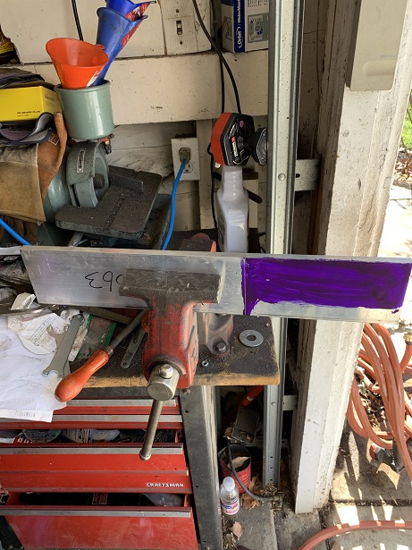
Posted by: 808 WRX Apr 26 2021, 02:39 PM
Therefore, this cradle is now available. I live in the northern California bay area. If anyone is interested in it and not wanting to wait for one to be built by Coldwater, mine is now available.
I am interested in your cradle, I sent you a PM. I'm in San Jose, so close enough to pick up.
Posted by: rmarx Apr 27 2021, 11:59 AM
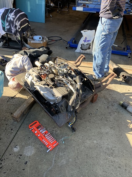
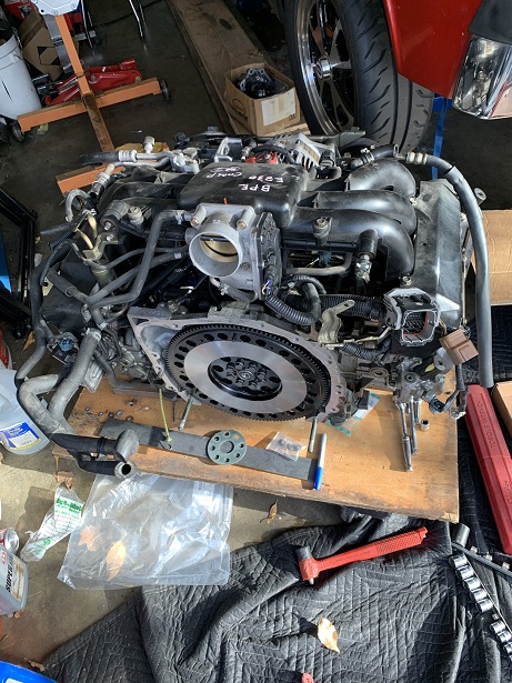
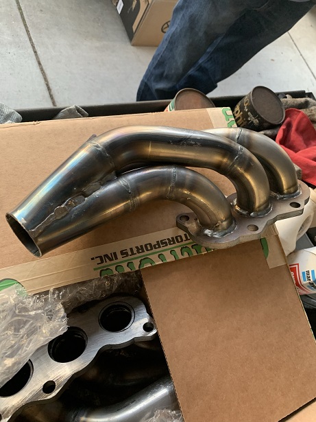
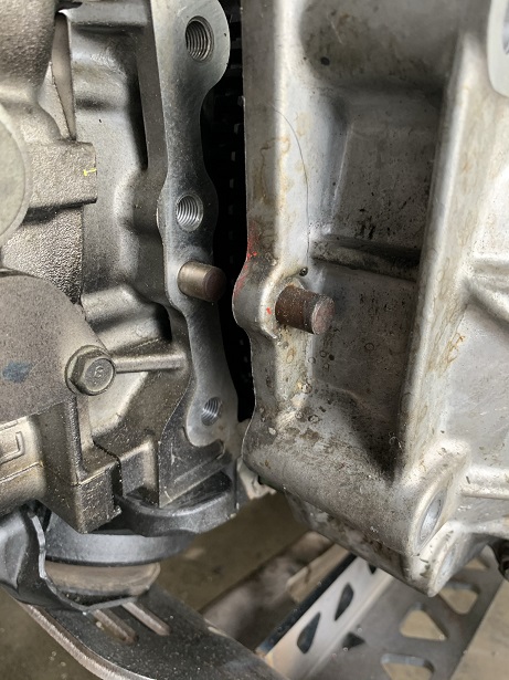
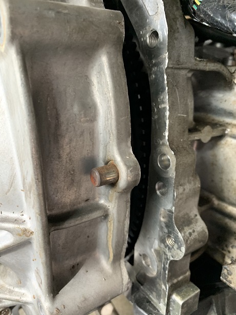
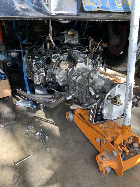
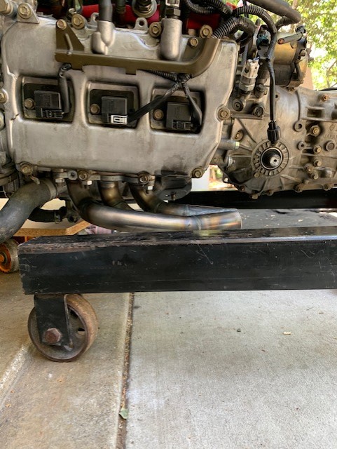
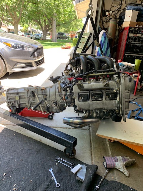
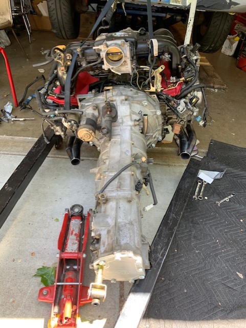
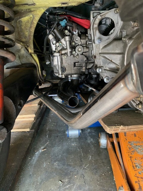
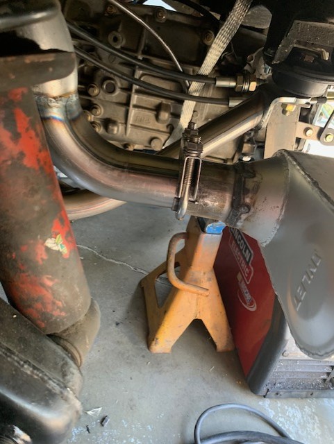
A couple pictures of the headers I got from Outfront Motorsports. They are nicely done and look to add power to my engine. A couple pictures of something to look out for when mating the trans to the engine. There are locating pins on the engine and the trans. I had to remove the pin from the trans to allow them to fit together. A picture of the engine and trans as they are being installed in the car.
Attached image(s)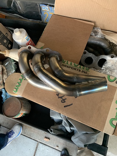
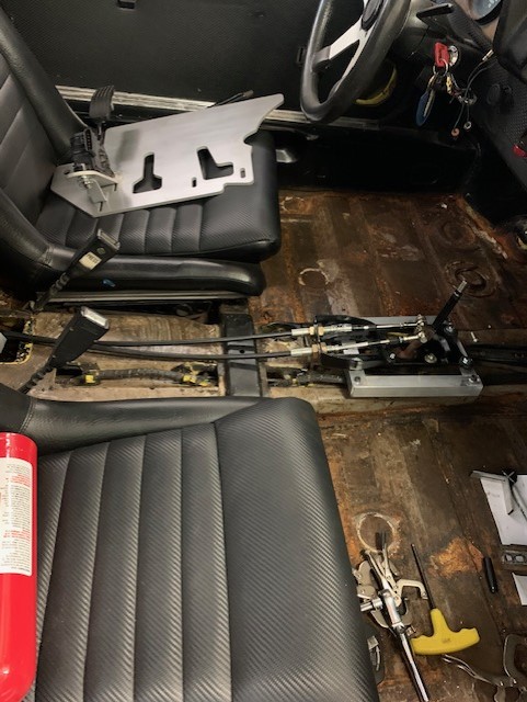
Posted by: rmarx May 5 2021, 11:01 AM
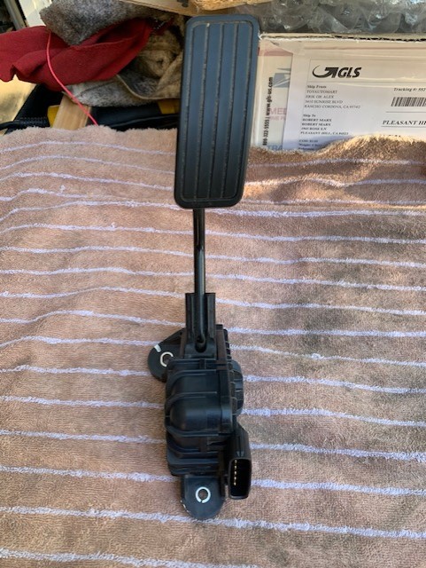
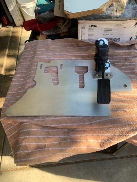
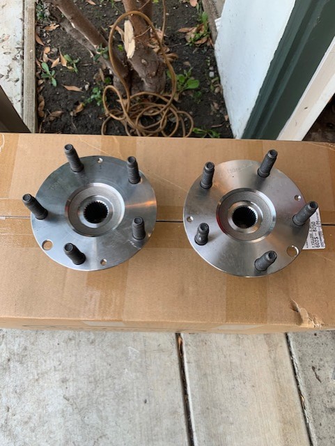
Look what just came in the mail! I just received my new floorboard set up for a Fly by wire throttle. I also received my new rear 5 bolt hubs from PMB. They look pretty good.
Attached image(s)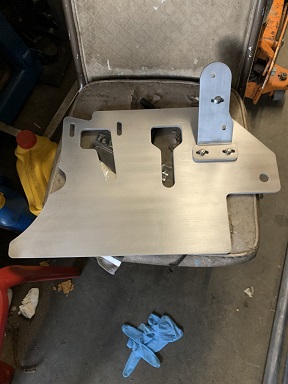
Posted by: willieg May 5 2021, 08:08 PM
Look what just came in the mail! I just received my new floorboard set up for a Fly by wire throttle. I also received my new rear 5 bolt hubs from PMB. They look pretty good.
The hubs look great. Definitely an easier transition to 5 lug than previous.
Posted by: rmarx May 17 2021, 11:16 AM
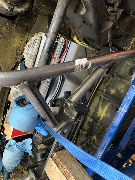
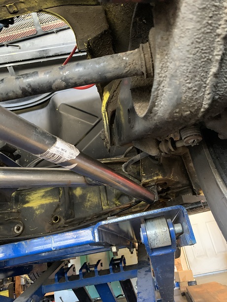
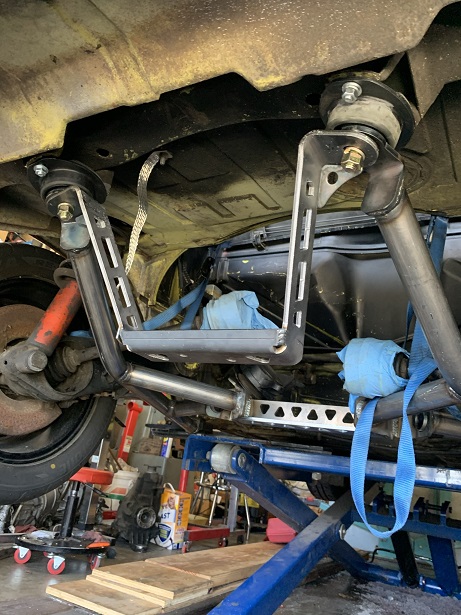
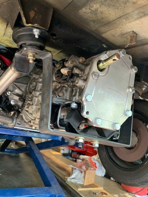
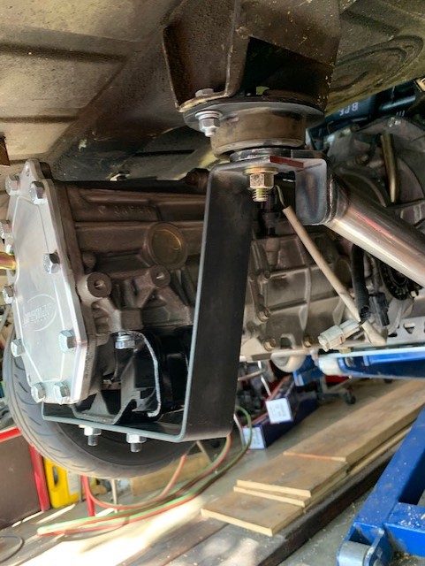
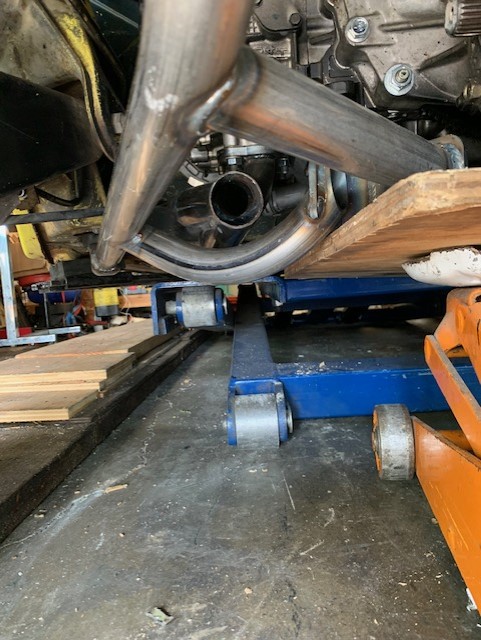
I received my new "modified" cradle from Coldwater 914. It had one of the side braces modified to clear my header. Lots of pictures showing the headers installed on the motor, the cradle mounted to the motor and finally the engine and cradle installed in the car. I had to make my own transmission mount to accommodate the for and aft positioning of the motor /trans combination.
It is finally in the car!
Next thing to do it modify the chassis to make clearance for the intake manifold, starter, clutch slave cylinder and actuating arm.
After that it will be time to measure for the axles and have them sent out to be modified to accommodate the Subi inner and 914 outer CVs.
Attached image(s)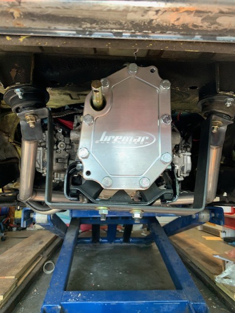
Posted by: rmarx May 20 2021, 10:41 AM
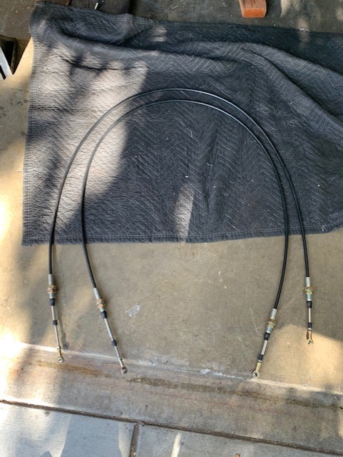
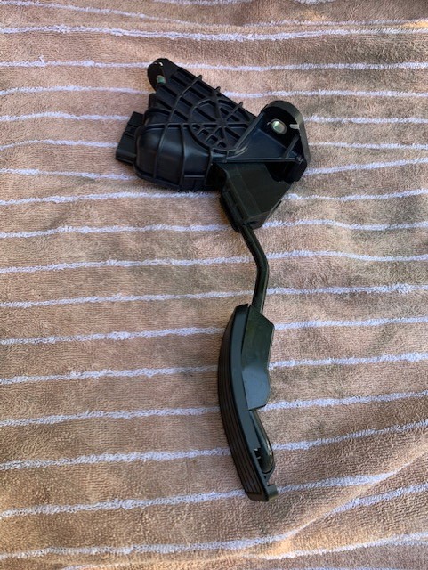
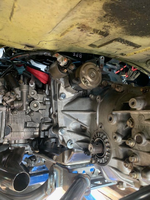
I received shift cables and the rear linkage for the transmission shifter from Coldwater 914. I think I will try this for now and possibly convert to my billet bracket shown in an earlier post at a later time. I received my fly by wire accel pedal from ebay and attached it to my newly acquired floor board. It looks pretty nice. After the motor and trans were installed in the car, I remounted my starter. It seems to have the clearance that I need without having to cut up trunk floor.
Attached image(s)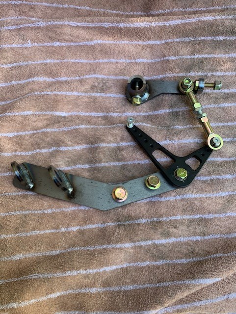

Posted by: grantjd May 20 2021, 10:51 AM
Is that the stock Subaru starter?
Posted by: Mayne May 20 2021, 11:36 AM
Looking great, and that's good news on the starter fitment.
Posted by: rmarx May 20 2021, 03:58 PM
Is that the stock Subaru starter?
Yes, at least I think so. It is the one that came with the trans when I bought it.
Posted by: rmarx Jun 1 2021, 11:26 AM
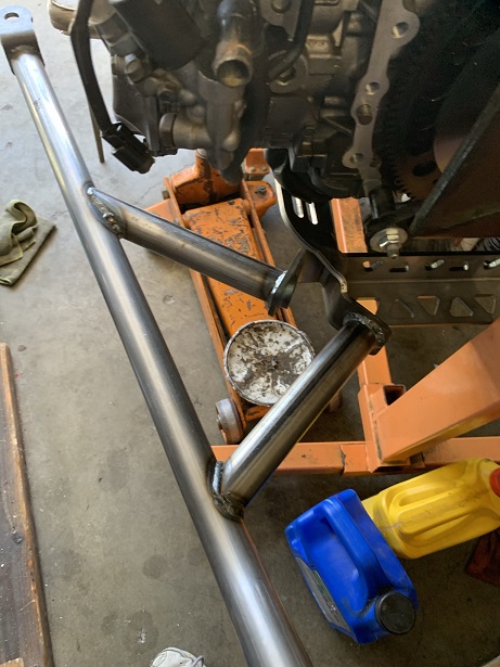
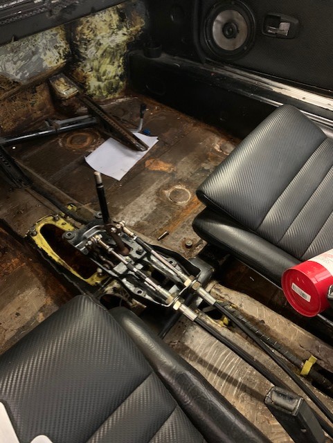
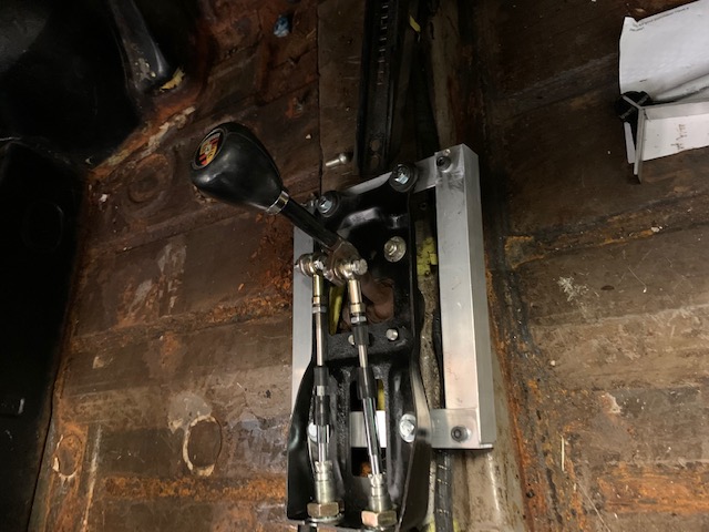
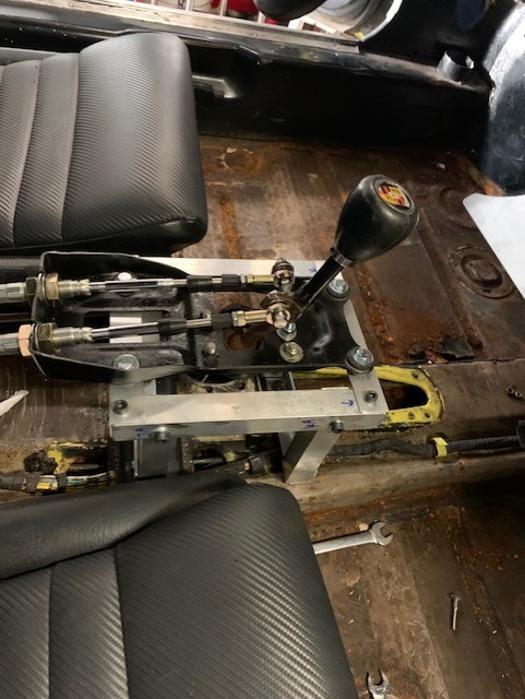
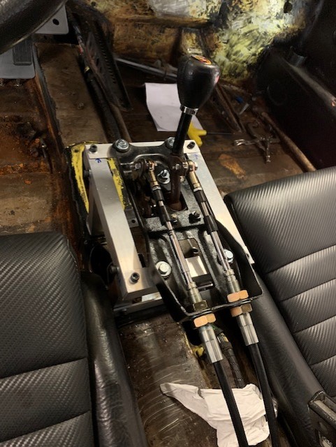
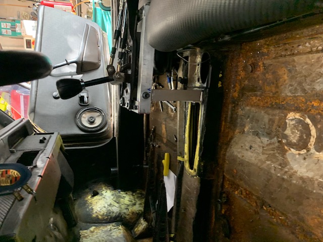
A little progress being made on the installation of the complete shifting mechanism. I installed the Coldwater 914 shift linkage to the transmission. I then installed the shift cables, (also supplied by Coldwater 914) and ran them though the hole that was once occupied by the shifting rod, ( let's refrain from the obvious jokes that will surely follow from that last statement). In order to connect the Heim joints on the cable to the shifter, I purchased some bronze bushings from Ace hardware that just happened to have an OD of 3/8" and an ID of 1/4". I placed a washer over the bushing to give it more clearance so that the Joint would not bind and hit metal during operation.
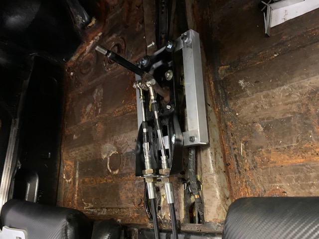
It was then that I decided to build a stand for the shifter to be mounted on. The whole idea was to locate the shifter higher and closer to me so that I would not have to reach so far to shift from gear to gear, as in a stock 914.
Being a weekend with most metal stores closed, I had to come up with a solution that I could do on a Sunday. So I went to Ace Hardware and bought some 1" aluminum angle and 1" square tubing and began to construct a box that the shifter could be mounted on. It is held together with 6mm Allen head screws and Nut-Certed where needed.
I am happy to report that this thing has all five gears along with reverse. It shifts like a Miata with a short shift kit installed. I have never felt a shifter that is this short, precise and crisp. I can't wait to see how it feels while driving.
Attached image(s)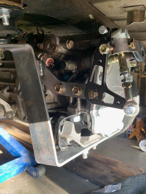
Posted by: 76-914 Jun 1 2021, 08:10 PM
Yep, you're going to like that location for your shifter and you've already tasted the fruit of this smooth, short throw combination.
Posted by: grantjd Aug 12 2021, 10:58 AM
the public demands updates!
Posted by: rmarx Aug 16 2021, 01:05 PM
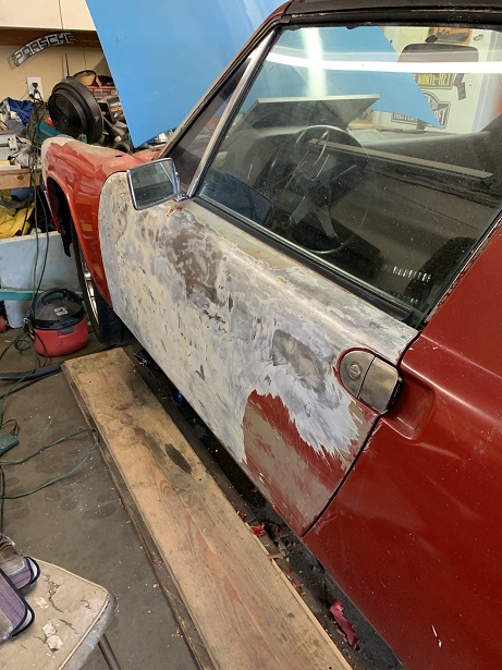
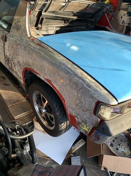
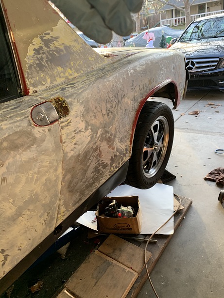
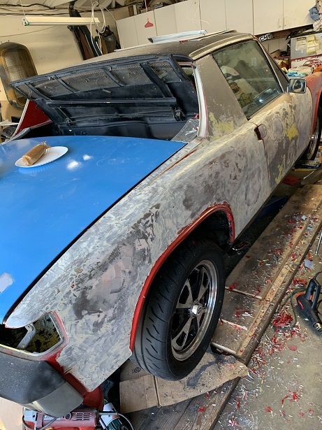
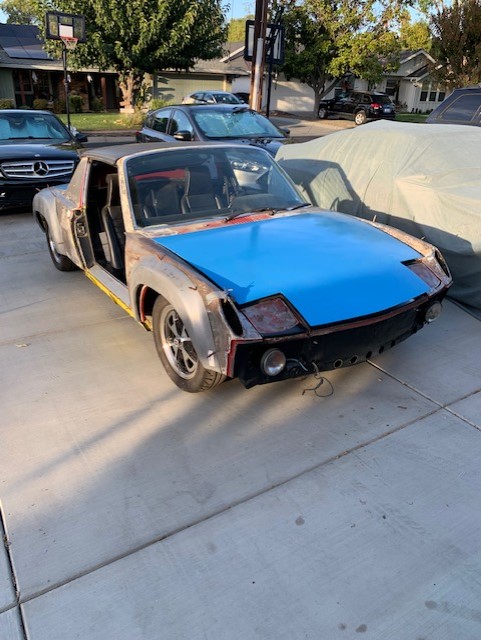
Sorry for the slow updates, I have been painting my house and attended car shows, (Reno Hot August Nights and Monterrey car week). I have managed to work on the car a little here and there.
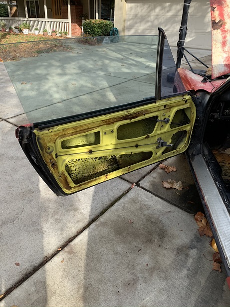
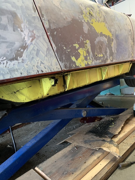
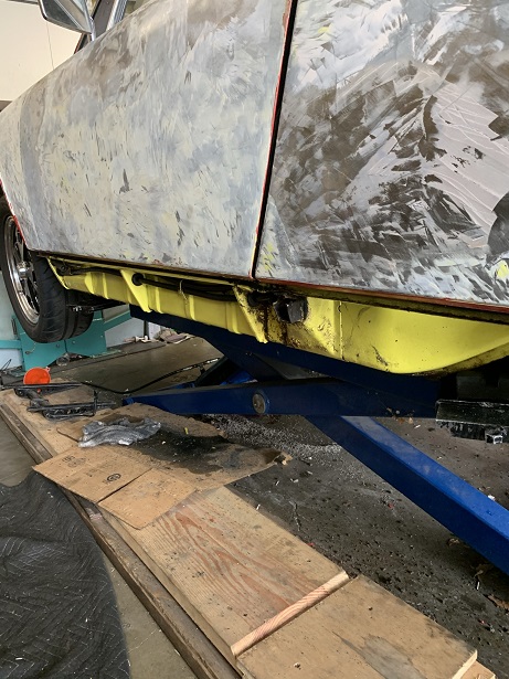
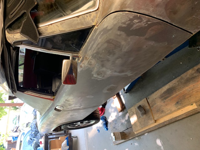
I got some aircraft paint remover and began stripping the paint from the exterior of the car along with the rear trunk. The car is basically straight. Both doors will need a little work to make them straight. All in all, I am happy with what I found under the old paint.
I installed my pedal box and began to plumb the hydraulic clutch assembly. This is not an easy job. There is very little room to work with, but I think I have got it solved.
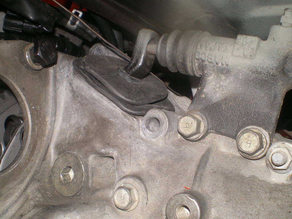
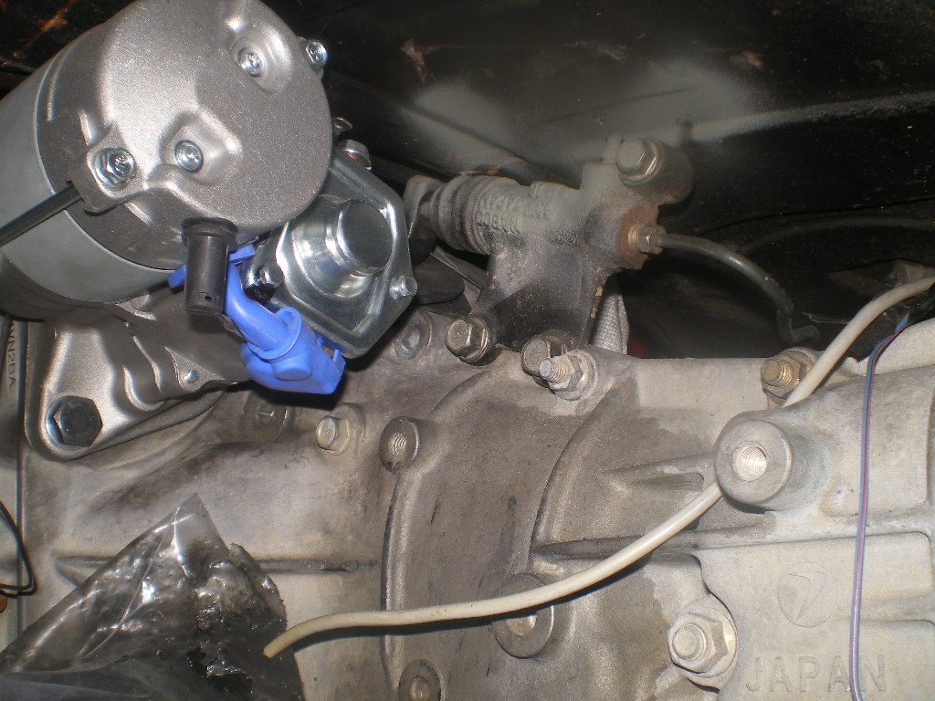
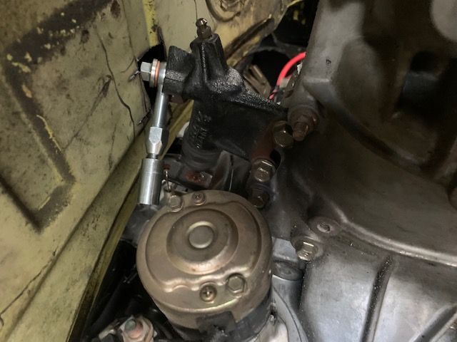
I am running in to a problem with the gap in between the throw out bearing release arm and the rod from the clutch slave cylinder. It is too large. I think the should be touching, but there a gap of approximately 1/2-3/4 of an inch. I don't know if I installed it wrong or the the slave cylinder rod needs to be extended. (pictures of that to follow).
Attached image(s)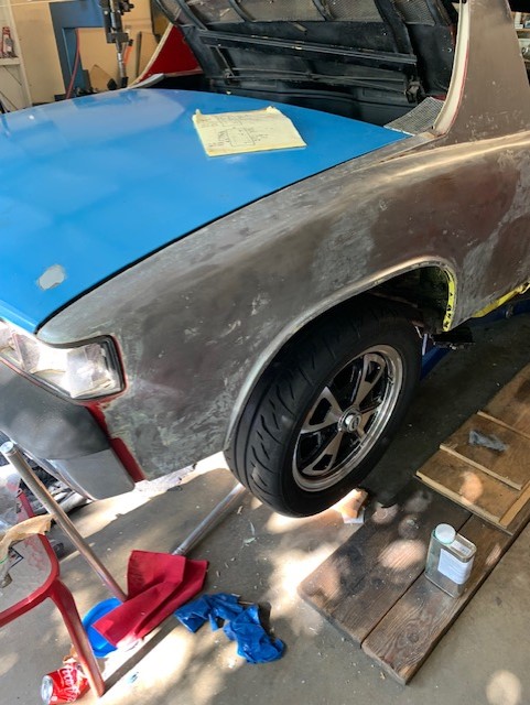
Posted by: tygaboy Aug 16 2021, 05:27 PM
I've always enjoyed watching a good strip show. ![popcorn[1].gif](style_emoticons/default/popcorn[1].gif)

Posted by: 76-914 Aug 17 2021, 05:13 PM
Sorry for the slow updates, I have been painting my house and attended car shows, (Reno Hot August Nights and Monterrey car week). I have managed to work on the car a little here and there.
I got some aircraft paint remover and began stripping the paint from the exterior of the car along with the rear trunk. The car is basically straight. Both doors will need a little work to make them straight. All in all, I am happy with what I found under the old paint.
I installed my pedal box and began to plumb the hydraulic clutch assembly. This is not an easy job. There is very little room to work with, but I think I have got it solved.
I am running in to a problem with the gap in between the throw out bearing release arm and the rod from the clutch slave cylinder. It is too large. I think the should be touching, but there a gap of approximately 1/2-3/4 of an inch. I don't know if I installed it wrong or the the slave cylinder rod needs to be extended. (pictures of that to follow).
I've always enjoyed watching a good strip show.
Me too Chris. Just be sure to get out of there before closing time when they turn the inside lights back up to 100% and you see what those girls really look like.
Posted by: willieg Aug 17 2021, 05:55 PM
Bob: Thanks for the updates. I enjoy dropping by to see what trouble you have created. That Subi engine, with headers, minus emissions, is going to roar.
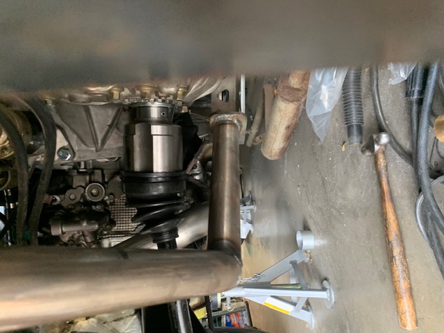
Posted by: rmarx Aug 19 2021, 10:39 AM
See attached pictures of the excessive clearance between the throw out bearing release arm and the clutch slave cylinder rod.
I don't know if I installed the release lever wrong, or the rod needs to be lengthened.
Attached image(s)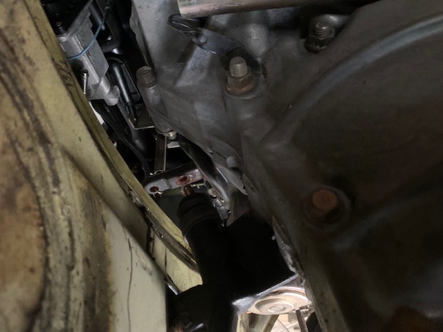
Posted by: 76-914 Aug 19 2021, 11:32 AM
I don't think that is the correct slave cylinder. It is definitely different from the 2 that I have on my conversions. What is the TY# on your transmission.
Posted by: theer Aug 19 2021, 12:58 PM
Are you sure the T0B is locked into the clutch springs? With the slave cylinder removed you have to pull back on the release lever to get the TOB engaged. Then the lever will be all the way back with the slave rod pushed in. If the release lever is loose, it’s not engaged and won’t pull to release the clutch. At least that was my experience with mine (EJ20 & WRX trans).
Posted by: rmarx Aug 19 2021, 02:33 PM
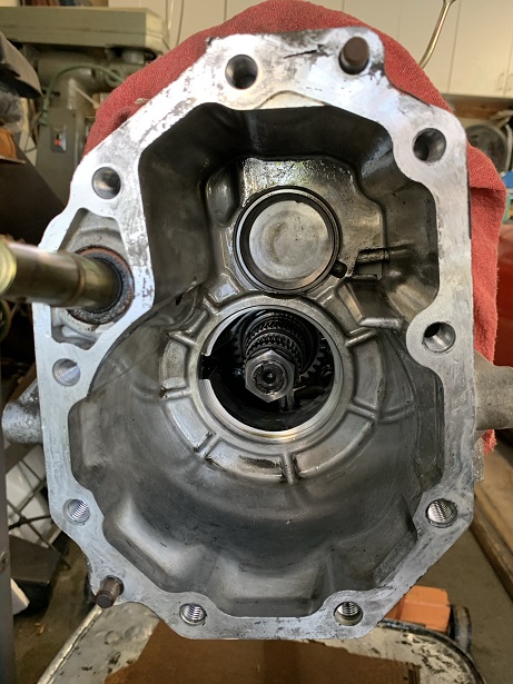
This a picture of what it looks like inside the bell housing before I put it together. I'm wondering it the two tabs popped out of the sockets...
Attached image(s)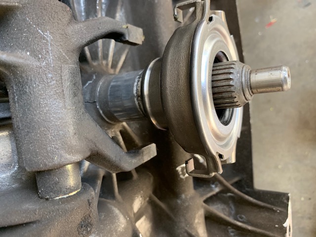
Posted by: theer Aug 19 2021, 03:43 PM
Looks a little different from mine, but my guess is you have the TOB reversed. The notch on the nose of the TOB engages with the locking ring on the clutch spring-fingers.
Posted by: jamlip Nov 15 2021, 03:11 AM
Hi Bob. Been a while. I've lusted after a swapped 914 since the day I shot that Retro Rides feature!
12 years on, I have one (well, a shell). I'm interested in putting an EZ30 in it and was delighted to find you doing just that, obviously.
I'm living in SoCal now. Hope to see you around some time

Jamie
Posted by: rmarx Nov 15 2021, 02:29 PM
Hi Bob. Been a while. I've lusted after a swapped 914 since the day I shot that Retro Rides feature!
12 years on, I have one (well, a shell). I'm interested in putting an EZ30 in it and was delighted to find you doing just that, obviously.
I'm living in SoCal now. Hope to see you around some time
Jamie
Hi Jamie, Long time no talk! Your excellent pictures of my last build helped to give me my 15 minutes of fame...
This new build is pretty cool. You will love the shifting on the transmission. It's like a Miata with a short shift kit. The motor should put out about 300HP. It should be quick.
Let me know if you are ever in town, let's get together.
Posted by: grantjd Feb 12 2022, 08:47 AM
Updates??
Posted by: 76-914 Feb 12 2022, 09:55 AM
Posted by: Chris914n6 Feb 12 2022, 02:46 PM
This a picture of what it looks like inside the bell housing before I put it together. I'm wondering it the two tabs popped out of the sockets...
That's backwards. The ring that spins needs to touch the PP. Also apply a LITTLE grease to anything that rubs.
Posted by: rmarx Feb 12 2022, 07:41 PM
Sorry for the long delay in updating the thread. My life got very busy as of late. I moved my office. I'm preparing my home for possible sale, and have been working on a separate
project. I have been making a Bomber seat for a friends Safari 911 with a little help from Tyga Boy.
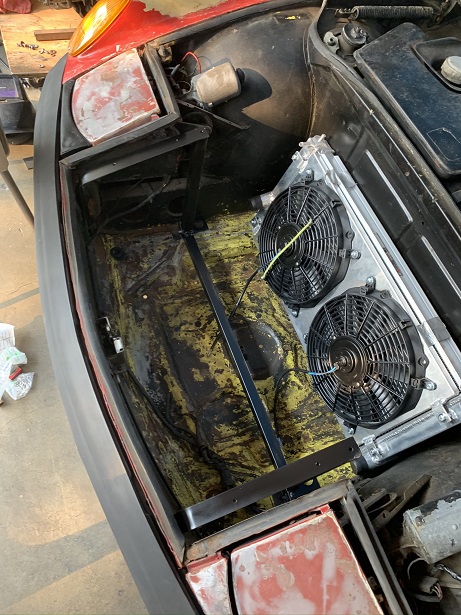
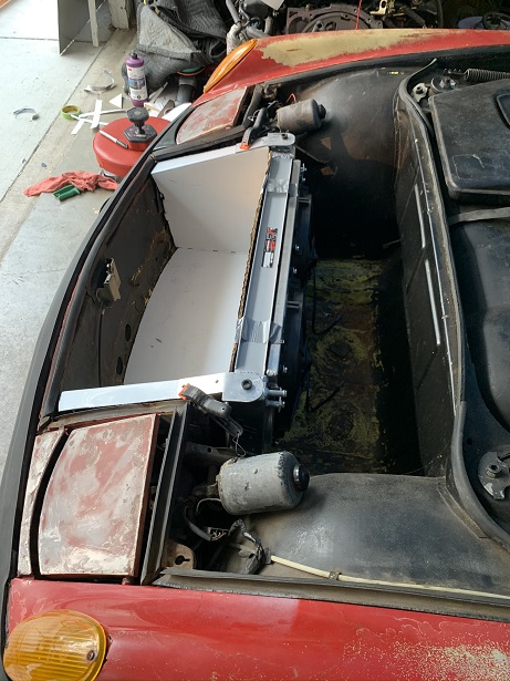
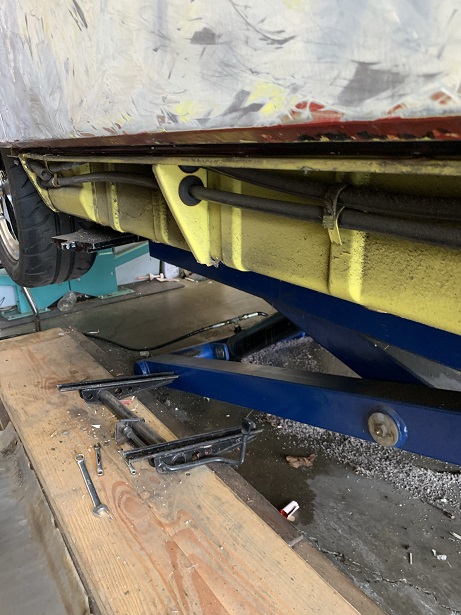
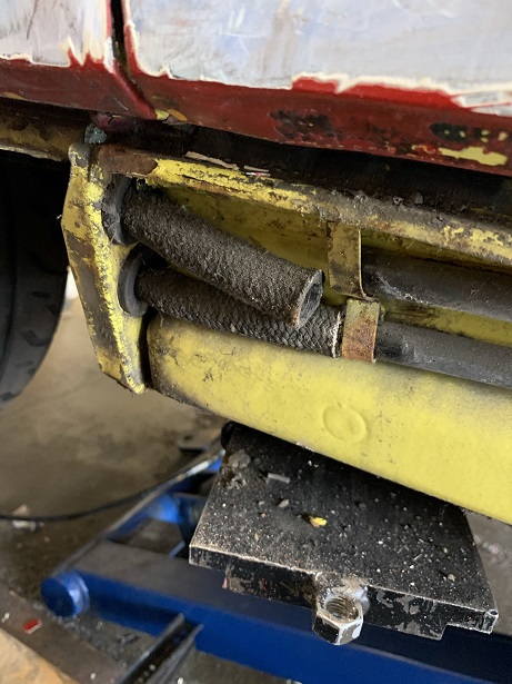
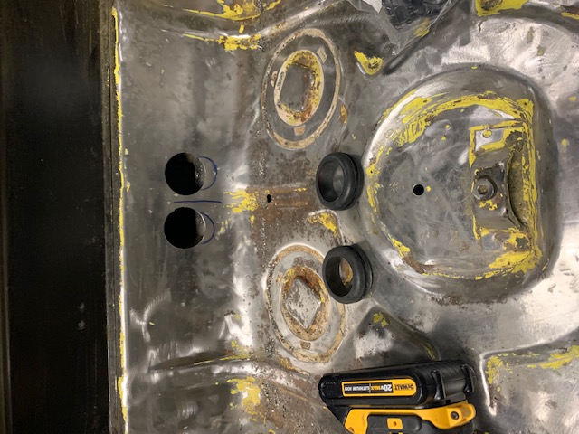
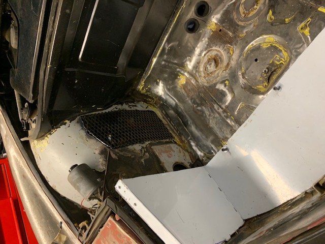
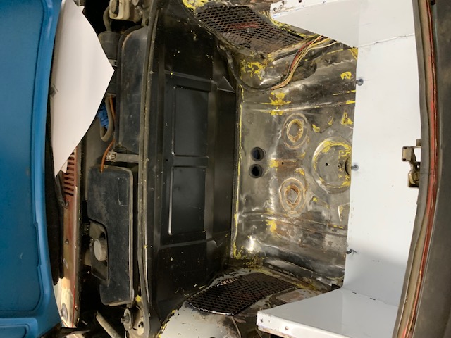
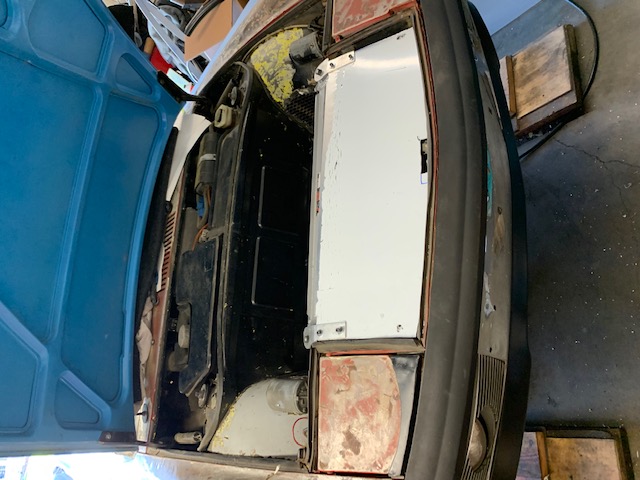
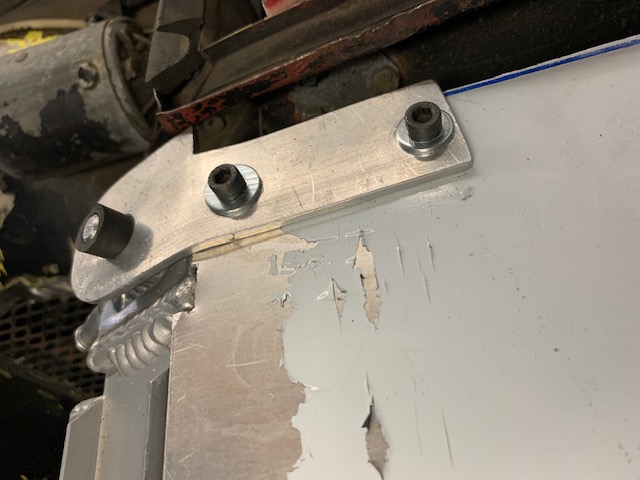
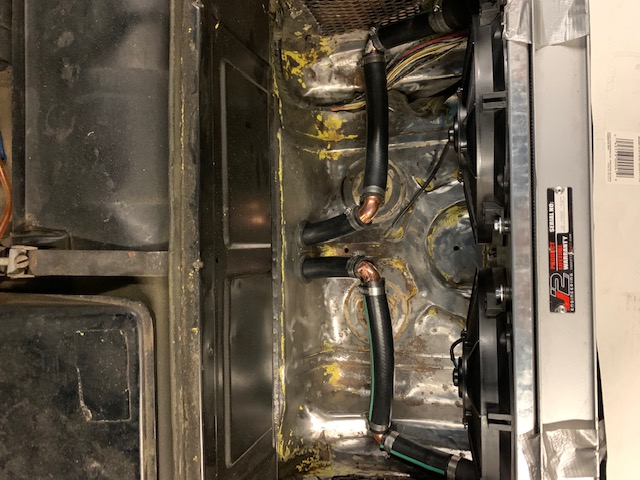
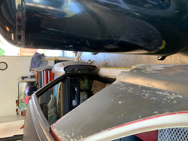
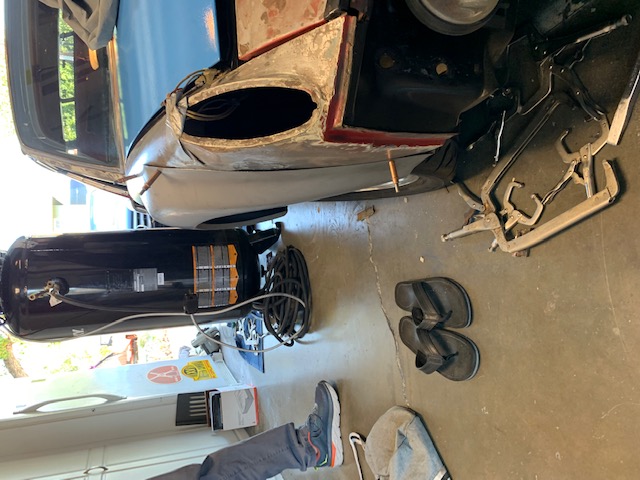
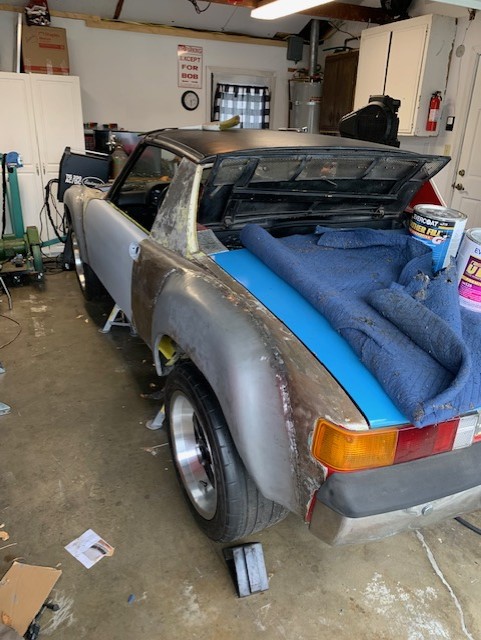
I have made a little progress on the cooling system. I installed the coolant hoses from the front to the to rear, I drilled the holes and installed the grommets to protect them while passing through the fire wall. I made the hose connection from the the hose to the radiator. As they exit the fire wall and proceed to the radiator, they kink, so I had to install 90 degree fittings to make sure they get full flow and are not restricted. What I did is not the the final product, I'm really not happy with the result, but it will work for now. I plan to make one piece aluminum tubes from the firewall to the radiator in the future.
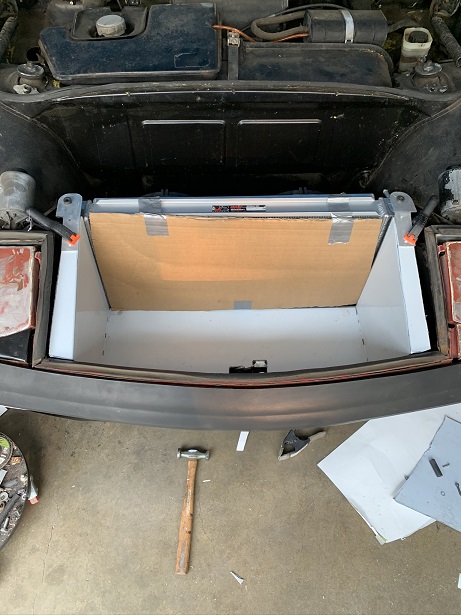
I completed the radiator and shrouding along with the top cover panel only to find that the hood would not shut and latch. GRRR.
I had to take it all apart and re-engineer it to make clearance. That meant cutting the frame apart, modify, re-weld along with cutting and reconfiguring the flanges on the shroud. After that, the brackets that hold the radiator to the frame had to be bent to properly fit.
Many of the things I am doing at this point are "proof of concept". I am just trying to get it to work. When completed and running, I will strip the car down to a bare shell, media blast, add the GT flares, paint the car, convert to 5 lug and make everything "pretty" as it goes back together. [attachmentid=826016] [attachmentid=826017]
Posted by: rmarx Feb 12 2022, 07:43 PM
Sorry for the long delay in updating the thread. My life got very busy as of late. I moved my office. I'm preparing my home for possible sale, and have been working on a separate
project. I have been making a Bomber seat for a friends Safari 911 with a little help from Tyga Boy.
I have made a little progress on the cooling system. I installed the coolant hoses from the front to the to rear, I drilled the holes and installed the grommets to protect them while passing through the fire wall. I made the hose connection from the the hose to the radiator. As they exit the fire wall and proceed to the radiator, they kink, so I had to install 90 degree fittings to make sure they get full flow and are not restricted. What I did is not the the final product, I'm really not happy with the result, but it will work for now. I plan to make one piece aluminum tubes from the firewall to the radiator in the future.
I completed the radiator and shrouding along with the top cover panel only to find that the hood would not shut and latch. GRRR.
I had to take it all apart and re-engineer it to make clearance. That meant cutting the frame apart, modify, re-weld along with cutting and reconfiguring the flanges on the shroud. After that, the brackets that hold the radiator to the frame had to be bent to properly fit.
Many of the things I am doing at this point are "proof of concept". I am just trying to get it to work. When completed and running, I will strip the car down to a bare shell, media blast, add the GT flares, paint the car, convert to 5 lug and make everything "pretty" as it goes back together. [attachmentid=826016] [attachmentid=826017]
Attached image(s)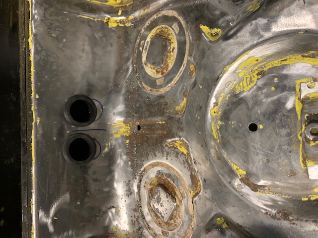
Posted by: rmarx Feb 12 2022, 07:45 PM
more photos
Posted by: rmarx Feb 12 2022, 07:45 PM
more photos
Posted by: rmarx Feb 12 2022, 07:46 PM
more photos
Posted by: rmarx Feb 12 2022, 07:46 PM
more photos
Posted by: rmarx Feb 12 2022, 07:47 PM
more photos
Posted by: rmarx Feb 12 2022, 07:51 PM
more photos
Posted by: rmarx Feb 12 2022, 07:51 PM
more photos
Attached image(s)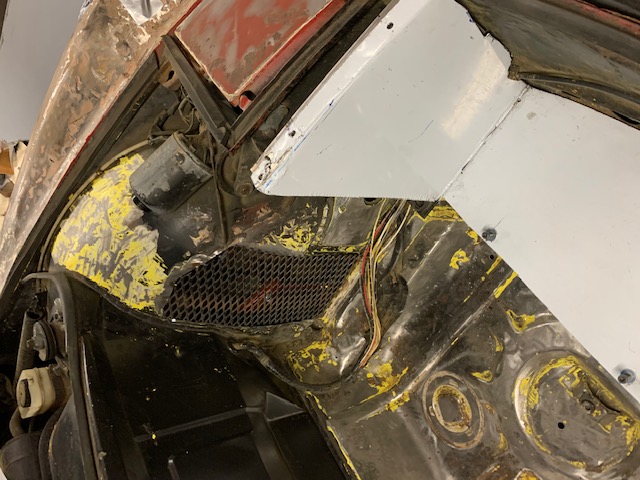

Posted by: 76-914 Feb 12 2022, 10:18 PM
I'm surprised the electrolysis police haven't commented yet. They did when I used some copper fittings.  Some people read about it but fail to fully understand it. Bottom line; you have an aluminum engine, trans and radiator so basically no worries. Be sure to ground your Subaru trans just as the 901 was to be complete. You can add an anode rod to your radiator to insure it has a long life. BTW, I inspected a couple of my copper fittings after 20K and maybe a 2mm BB of aluminum on one of them. Good to see you back at it.
Posted by: rmarx Jul 5 2022, 08:07 PM
Major changes in my life... I have decided to go another direction with this project .
I am offering this project car along with many parts for sale.
5 bolt conversion parts: 911 SC front struts with calipers and rotors. PMB rear 5 bolt hubs and studs.
Brand new in the box GT flares.
7", 8" and 9" x 16" replica Fuchs
Brand new ECU Master ECU along with conversion plugs and wiring harness for the Subaru motor.
Brand new Subaru axles.
New Carpet kit
All the parts listed in the thread to this point.
PM me or call my cell @ 925 708-2698.
Bob
Posted by: rmarx Oct 10 2022, 11:12 AM
I'M BACK!
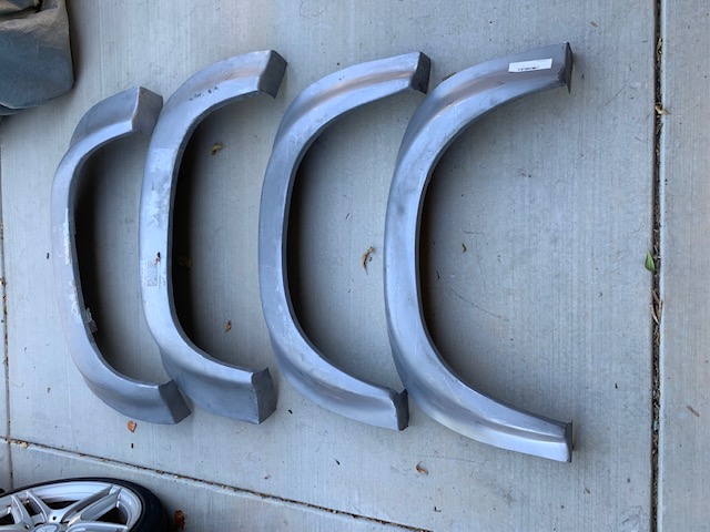
Things have changed for the better. I have decided to continue with this project.
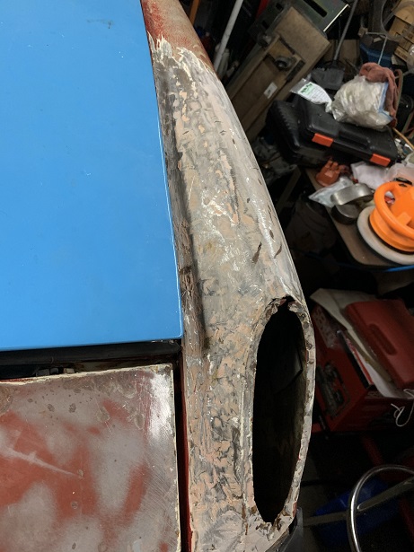
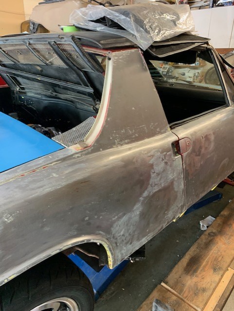
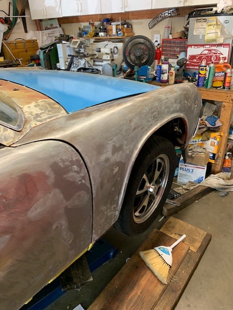
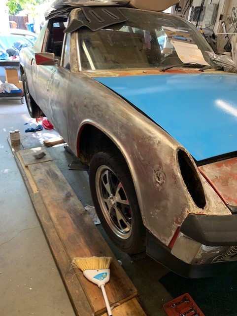
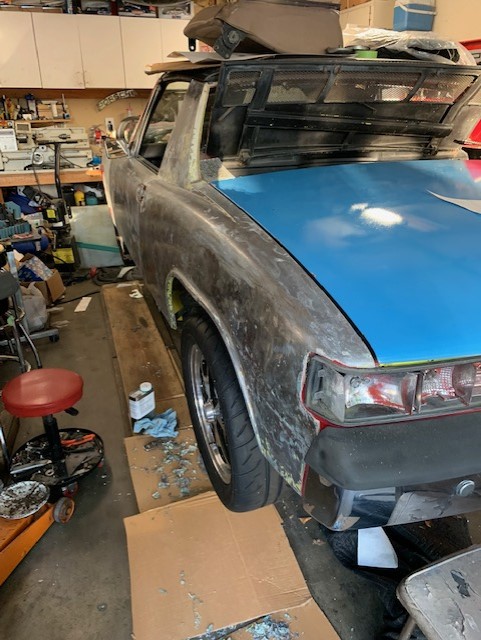
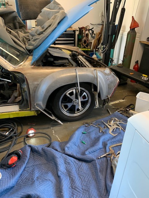
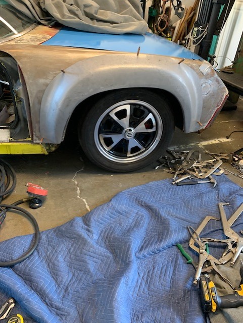
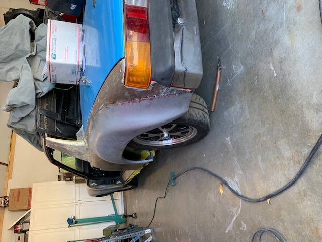
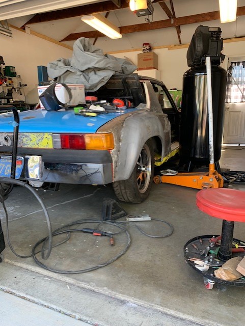
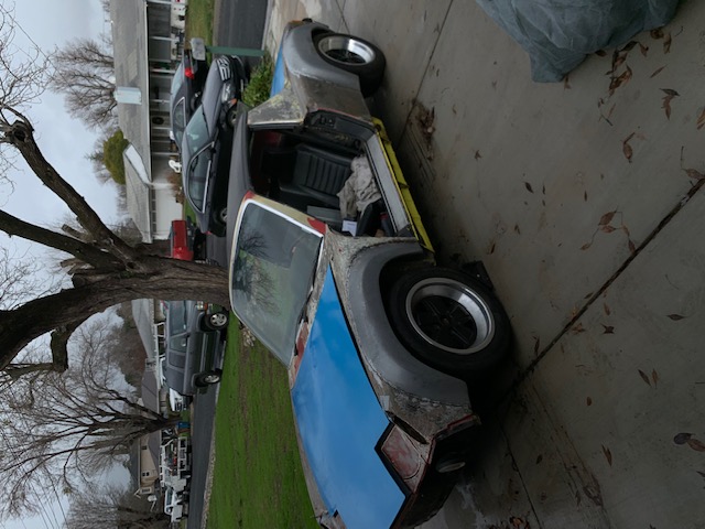
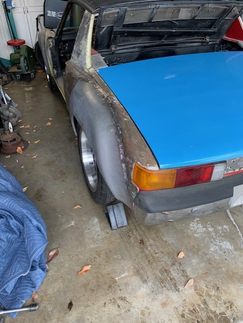
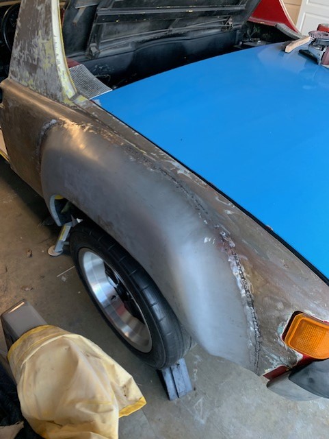
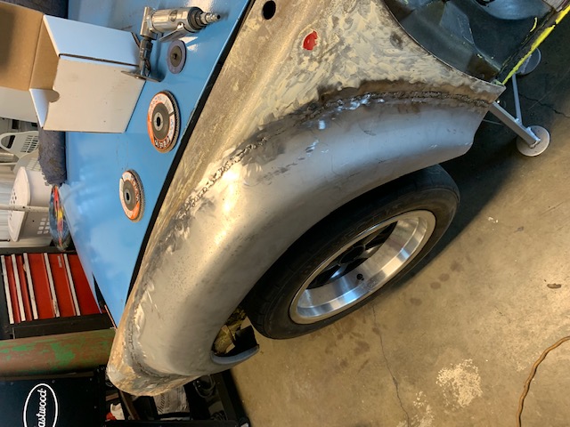
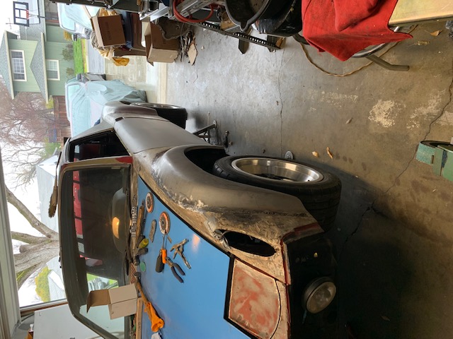
I began by starting the GT flare conversion. I've posted pictures of the flares as I received them to before and after shots of the right front flare installation.
I won't cut the body and weld them permanently until all four are mocked up to verify correct fitment.
One detail of note when doing the flare installation is that you must cut away the bottom flange section of the existing body in order to fit the flares to the body. The flares won't fit flush if you don't...
Attached image(s)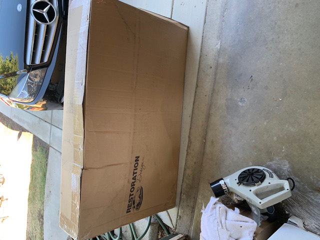

Posted by: willieg Oct 10 2022, 01:59 PM
The flares are looking great already. Bad Ass!
Posted by: tygaboy Oct 10 2022, 05:35 PM
Ima start callin' you "Jed". Jed Clamp-it!
Posted by: rmarx Oct 17 2022, 04:13 PM
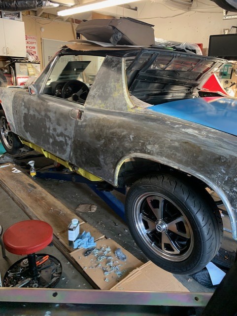
I have mocked up all four flares and am ready to weld them in permanently.
Attached image(s)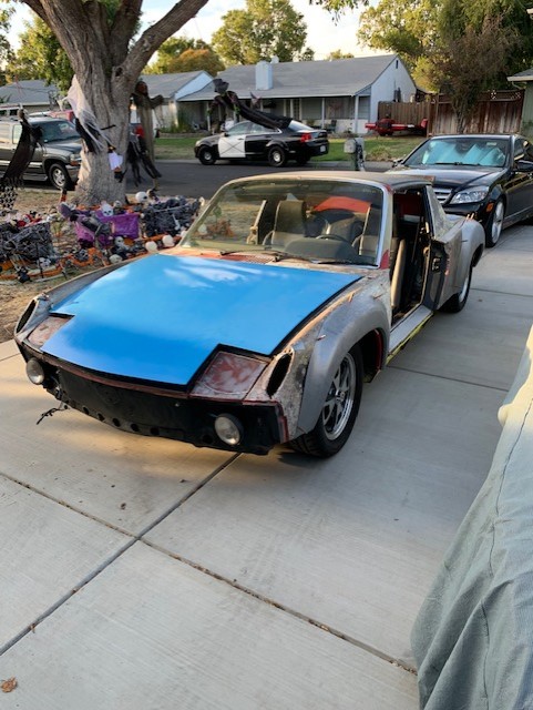
Posted by: grantjd Oct 18 2022, 08:06 AM
Excited to hear this fire up
Posted by: Cairo94507 Oct 18 2022, 10:09 AM
Major transformation- very exciting.
Posted by: rmarx Oct 18 2022, 10:48 PM
The first flare to be permanently mounted. I will finish the welding and metal finishing once all the flares are mounted.
Attached image(s)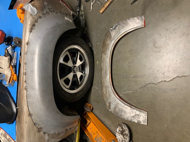
Posted by: rmarx Oct 24 2022, 10:25 AM
The remaining three flares are now mounted and tacked welded to the chassis. Final welding and metal finishing to follow.
Next up, 911 SC strut recondition. New paint, Bilstein inserts, bearings etc.
Upon completion of that, I will install them to begin the 5 bolt conversion.
Attached image(s)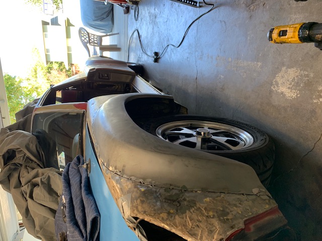
Posted by: tygaboy Oct 24 2022, 10:31 PM


Posted by: rmarx Nov 6 2022, 07:13 PM
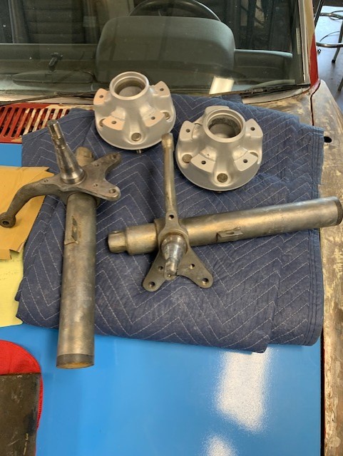
I got a pair of 911 SC front struts that had been sitting around for many years. They were dirty and partially corroded. I began the disassembly of the the various components to begin their restoration. I first remove the calipers from the struts, then the hubs, then I separated the rotors from the hubs.
I began to clean the grease and grime from many years of neglect. I then bead blasted the struts, hubs and rotors.
I will paint the struts.
I will next replace the bearing races in the hubs and struts and reassemble the two together.
A couple pictures of how clean they came out. Sorry, I forgot to take a (before) picture.
Attached image(s)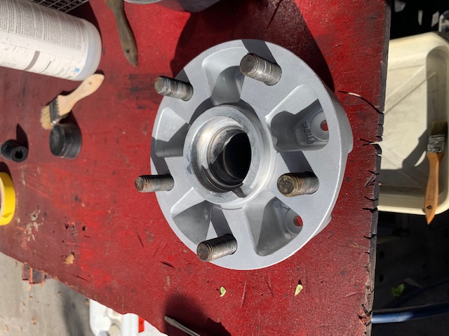
Posted by: rmarx Nov 28 2022, 01:32 PM
After many hours of standing while bead blasting the struts, rotors and hubs, I began to think "I'm getting too old for this sh*t". My feet, back and neck were killing me.
The good news is, progress has been made!
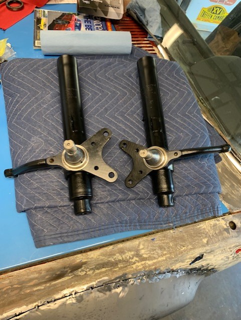
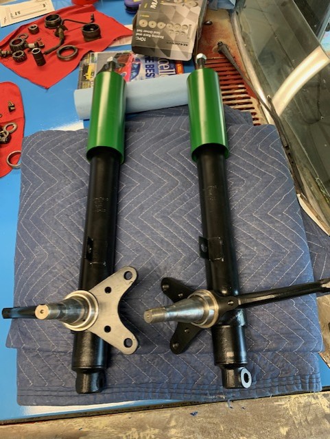
I replaced the seal race on the struts, ( they were was removed in error and subsequently thrown away, Grrr).
The struts were painted, new inserts installed (Bilstein) and now ready for installation.
The A arms were blasted and repainted.
New bearings, races and seals were installed in the hubs; rotors were bolted on and now the units were ready for installation.
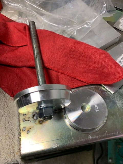
New ball joint were installed.
There is a special socket used to remove and replace the ball joints. It is an easy job when you have the right tools.
Much thanks to fellow 914 World member Mark Saunders for lending me the tool.
The 5 bolt front end conversion has been completed with exception of the calipers. They will be rebuilt and installed at a later time.
All put together now with temporary 6" Fuchs on the front. They will be replaced with 8s in the future/
Attached image(s)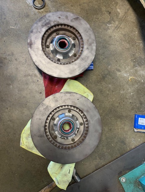
Posted by: willieg Nov 28 2022, 06:50 PM
Love the Tarrett front sway bar. I crawled under your car yesterday. Nice job on the turbo tie rod ends with boots.
Posted by: rmarx Dec 8 2022, 05:20 PM
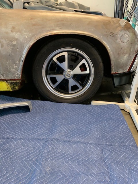
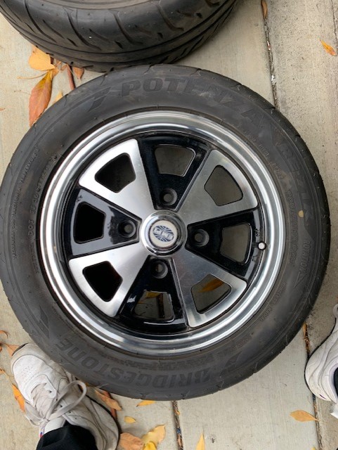
With the 5 bolt conversion more than half way completed, it is now time to sell my virtually brand new EMPI 4 bolt Fuchs replica wheels (5.5") mounted with Bridgestone Potenza RE71R tires. They are 205/50/15. They only have about 300-400 miles on them.
This will also include new lug bolts as well.
$750.00 for the set.
I will also list this in the classified section.
Attached image(s)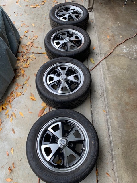
Posted by: rmarx Dec 8 2022, 05:37 PM
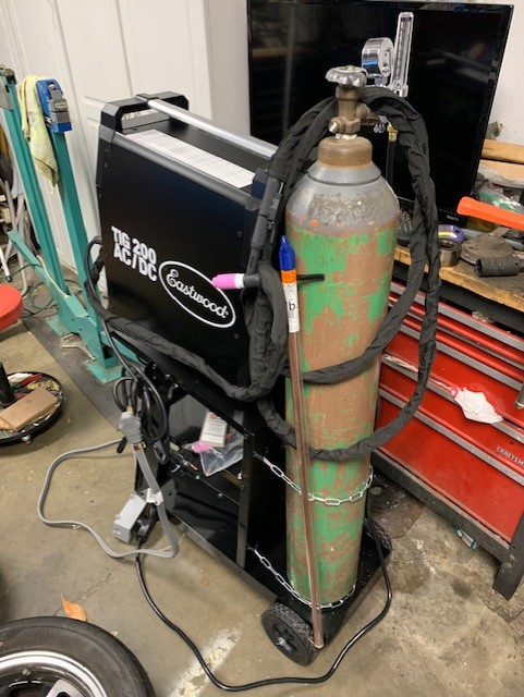
I treated myself to a nice birthday present last week.
I bought a new TIG welder from Eastwood. They had a great sale going on, so I thought "why not".
I recently sold my old HUGH Lincoln Square wave transformer welder. It was giving me problems, so I thought I would upgrade with a more modern unit.
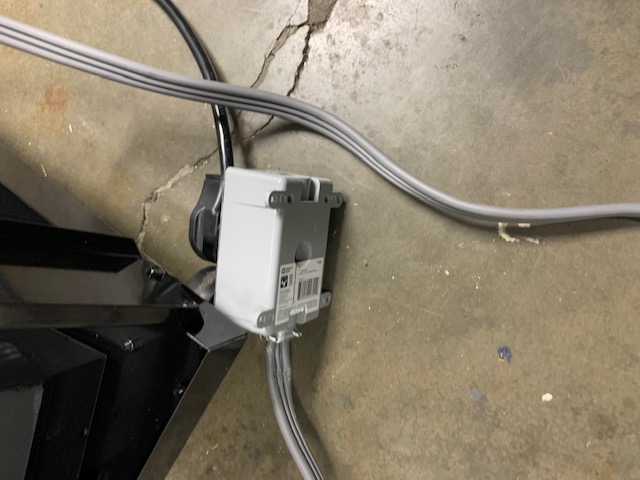
I also had to make a 50 amp to 30 amp conversion plug/extension cord while I was at it.
Happy birthday and early Christmas all wrapped up in one.
Attached image(s)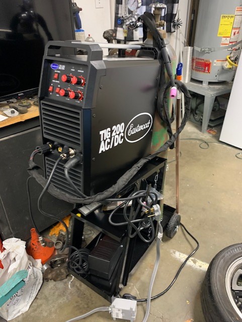
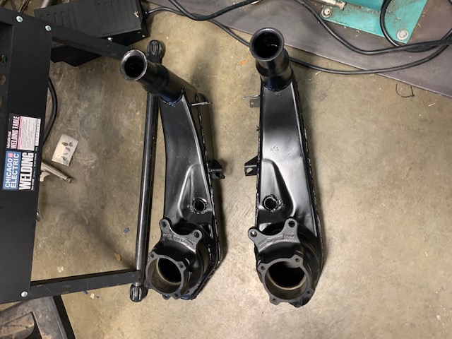
Posted by: rmarx Dec 26 2022, 08:14 PM
Happy Holidays everyone! I hope you all had a great Christmas.
More progress is being made.
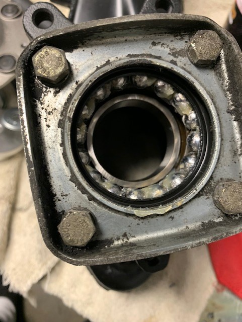
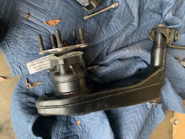
I removed the rear trailing arms. I then bead blasted, primered and painted them to give them a new refreshed look.
I have shown a before and after pictures to illustrate.
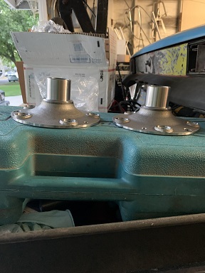
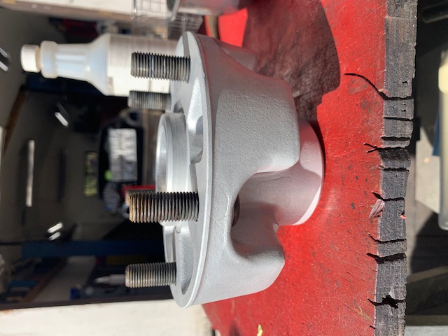
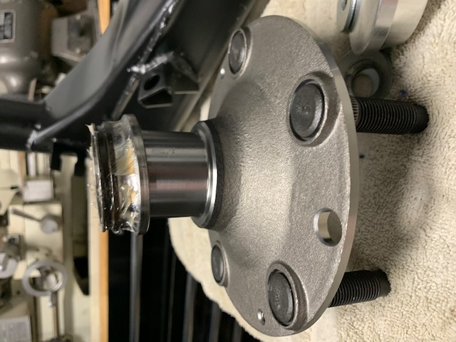
I then replaced the pivot bushings and main hub bearing. I used my new Harbor freight bearing and race removing tool to accomplish that task.
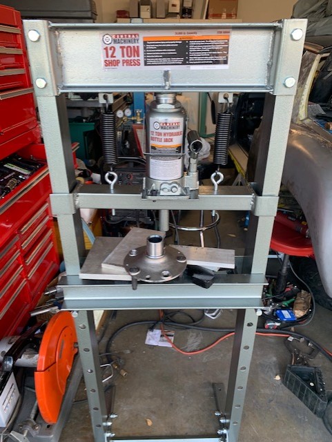
I then decided to give myself a present form Santa. I bought a Harbor Freight hydraulic press.
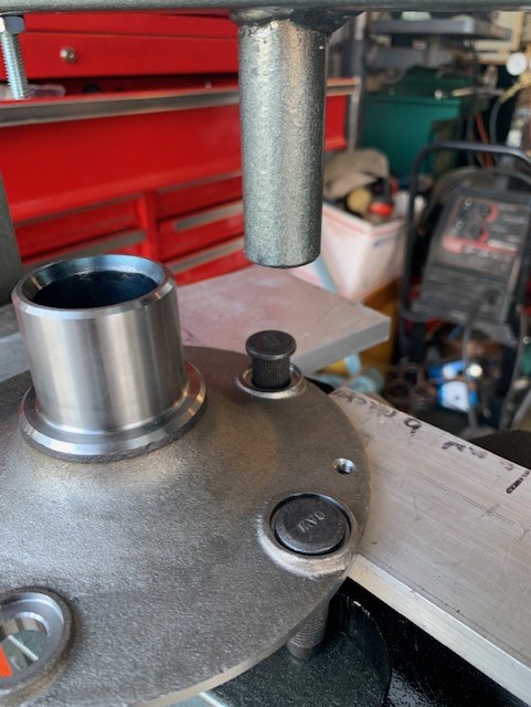
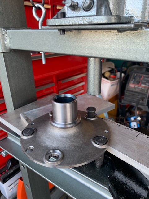
I used it to press in the new studs into my new PMB 5 bolt hubs. It is a little challenging trying to get it set up as each progressive stud is pressed into the hub. After using a few different pieces of metal to evenly distribute the load on the hub, it worked beautifully.
All was going well until I attempted to install the hub onto the trailing arm. I tried to be very careful and get the hub square to the trailing arm. It was off just a little, so I rocked it to adjust it and the bearing split apart. GRRR.
I decided to turn off the lights, shut the garage door, order a new bearing and try again another day.
Attached image(s)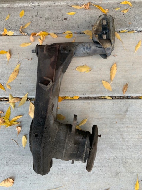
Posted by: tygaboy Dec 26 2022, 11:49 PM
Those trailing arms and hubs look GREAT! Sucks about the bearing but you'll get past this in no time!
Posted by: 76-914 Dec 27 2022, 09:29 AM
You'll end up using the press on lots of projects.
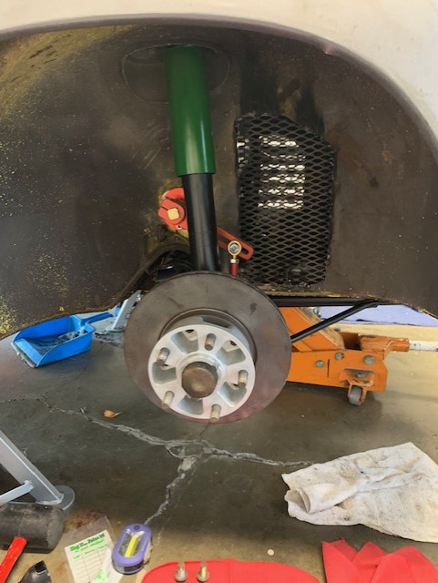
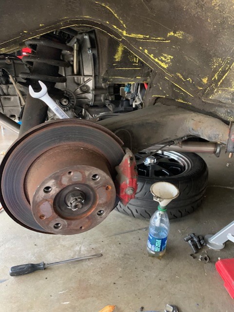
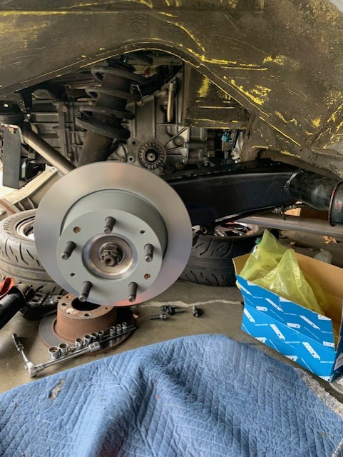
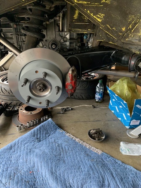
Posted by: rmarx Jan 16 2023, 06:14 PM
More progress!
When we left off last time, we had a broken rear bearing with the race stuck to the hub.
That was removed using the tapered bearing plates along with the press.
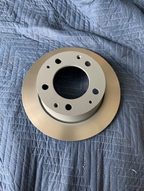
A new bearing was installed along with the rear hub. I mounted the right rear trailing arm to the chassis, installed the new 914/6 rear rotor and installed the original brake caliper.
The pads do not clear the new rotor, so I had to use the adjuster screws to back out the pucks to make room. So far they still don't clear, so for now I just left the pads out to keep things going.
Note: there is a little circlip on the adjuster screw to keep the locking nut from backing out. You must first remove it before you loosen the locking nut. If you don't, it will jam up the screw and make things nmore difficult.
Ask me how I know this...
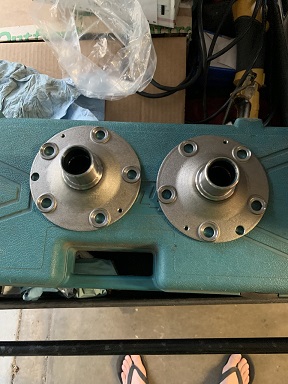
I moved on the left rear to complete the same process when I realized the new hub I received was mis packaged from the factory. They put in a 911 hub instead of a 914 hub.
The difference is that the 911 hub has 28 splines and the 914 hub has something like 32 splines. Of course when I tried to put in the axle, it would not go in.
I called the company and they were very good about it and sent me a new hub and bearing with the studs pressed in. ( Great customer service).
Once I received the new parts, everything went together just fine.
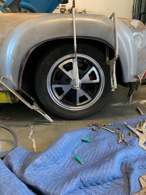
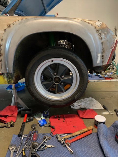
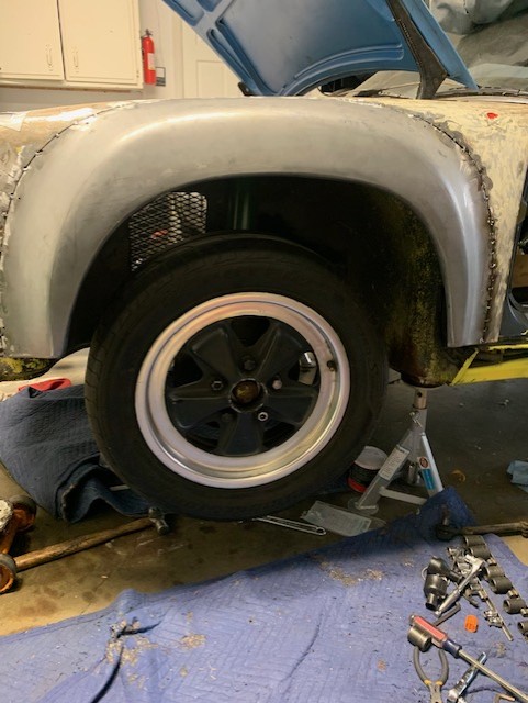
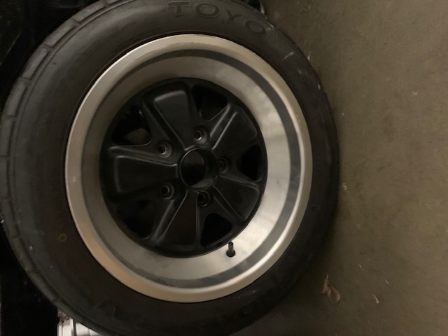
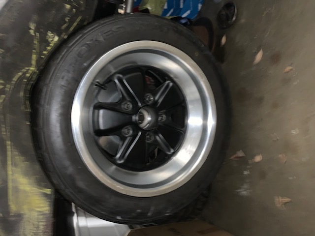
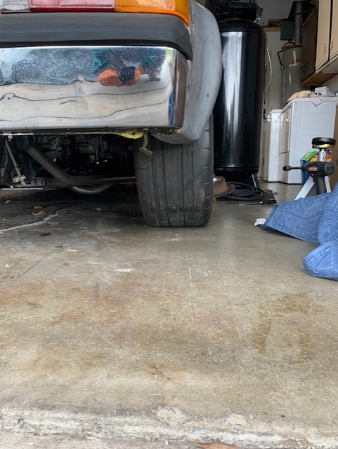
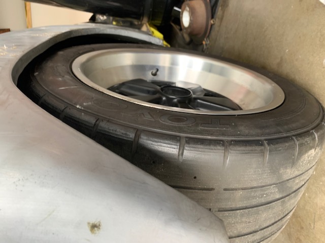
I then mounted my newly acquired Toyo Proxxes RA1 tires to my 8 & 9" wheels and mounted them on the car.
You ask "Wheres the beef?"
It's right here.
The wheels and tires completely fill up the space created from the flares and it looks great. I'm very happy.
Attached image(s)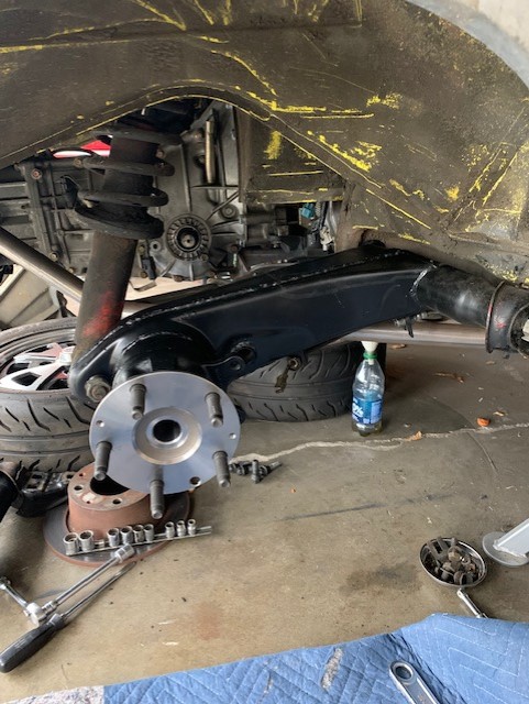
Posted by: 808 WRX Jan 16 2023, 06:31 PM
I was just wondering how your project was coming along... Looks good, nice to see the wheels on!
Posted by: willieg Jan 17 2023, 04:38 PM
Those wheels and tires are impressive. They certainly fill up the space.
Posted by: grom914 Jan 28 2023, 07:13 PM
I am doing this same engine swap! I will be following this build. Great job so far!
Posted by: willieg Jan 29 2023, 11:40 AM
That is a great engine for a 914. Subaru did their homework on the exhaust for this engine. Keep us up to date on your wiring progress, specifically what you are using for the ECU, and how the drive-by-wire ties in with the ECU.
Posted by: rmarx Feb 4 2023, 05:08 PM
I am doing this same engine swap! I will be following this build. Great job so far!
PM me or call @925 708-2698 ©. Let's compare notes...
Posted by: rmarx Feb 4 2023, 05:20 PM
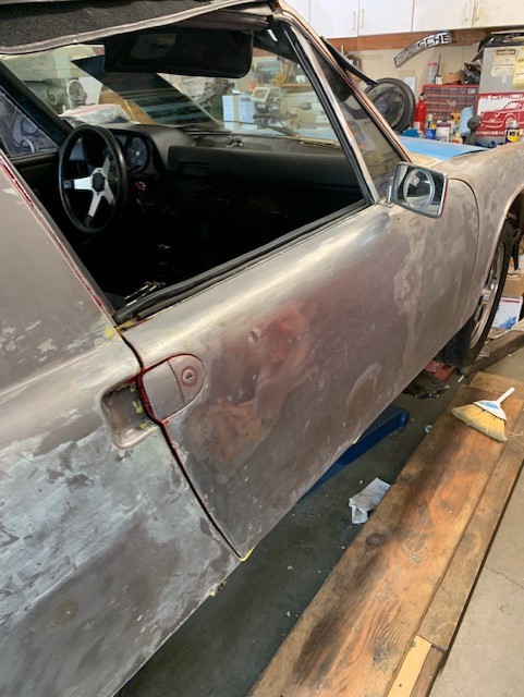
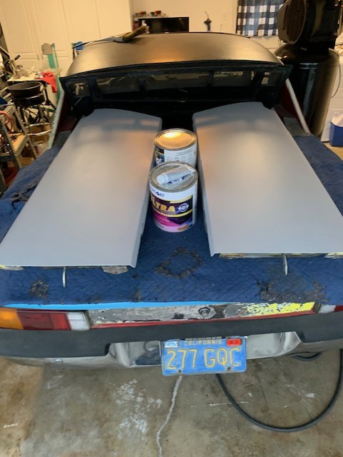
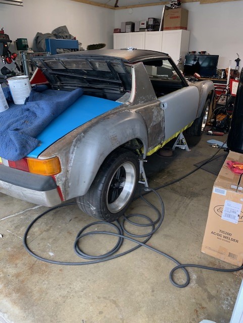
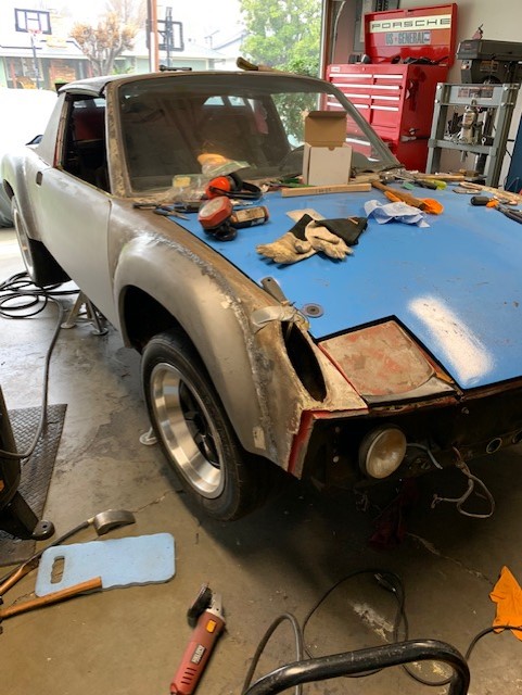
I have basically finished the welding of the flares. I will do a little more grinding before I apply the primer sealer to all four corners of the car.
I received my doors back from my body and paint guy (Mike Hynes). They were in pretty bad shape to begin with but after Mike pretty much straightening and metal finishing them, they are very straight and look great.
I mounted the doors on the car to get an idea of how it will look. It's starting to lok like a car again.
Attached image(s)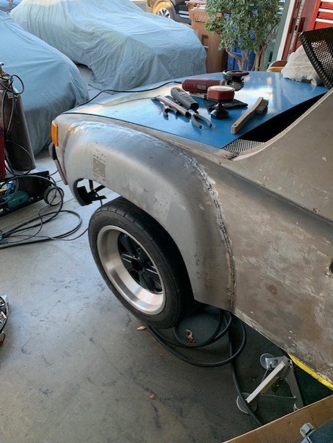
Posted by: Mayne Feb 4 2023, 07:21 PM
Looking great! I’m getting closer on my engine bay repairs, and then in goes EZ30 for the first time.
Posted by: rick 918-S Feb 5 2023, 08:18 AM
Nice thread
Posted by: tygaboy Feb 5 2023, 09:54 AM
Nice progress! Can't wait to see you get back on that wiring... 
Posted by: rmarx Jul 8 2023, 07:25 PM
It's been awhile. Much going on in my life, but the dust is finally starting to clear and I finally have some time to get to work on the car.
Much thanks to Chris Baker @http://www.914world.com/bbs2/index.php?showuser=19241 for help and motivation on getting back to working on the car.
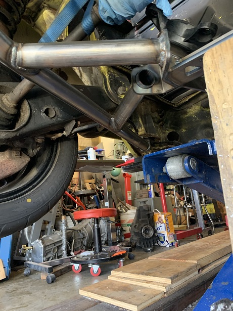
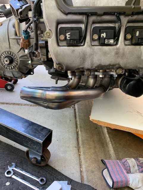
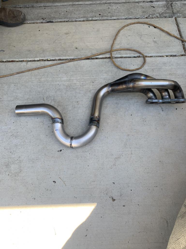
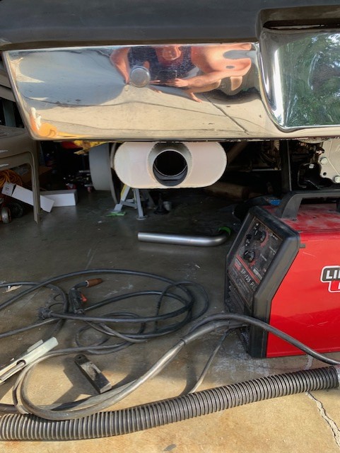
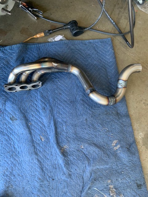
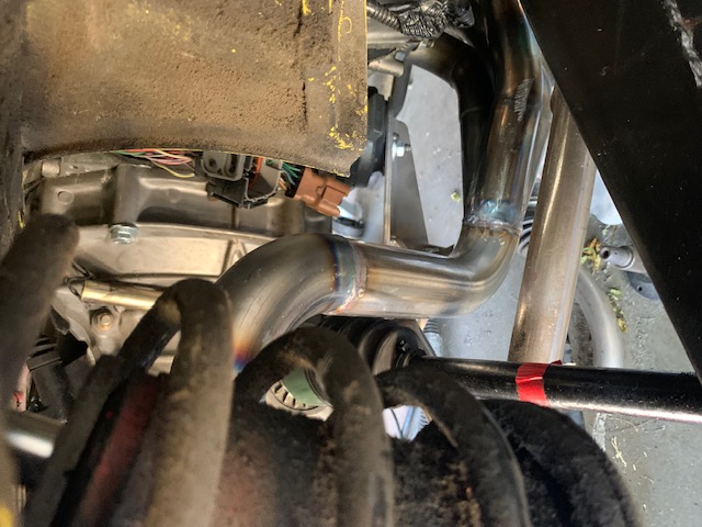
Today he came over and we started to build an exhaust system for the car.
The header is from Outfront Motorsports. The tubing and muffler are from Summit Racing.
We (mostly Chris) spent the day cutting, measuring, grinding and Tig welding one side of the system.
My next job will be to mount the mullers and basically copy the side just completed for the other side of the system.
Attached thumbnail(s)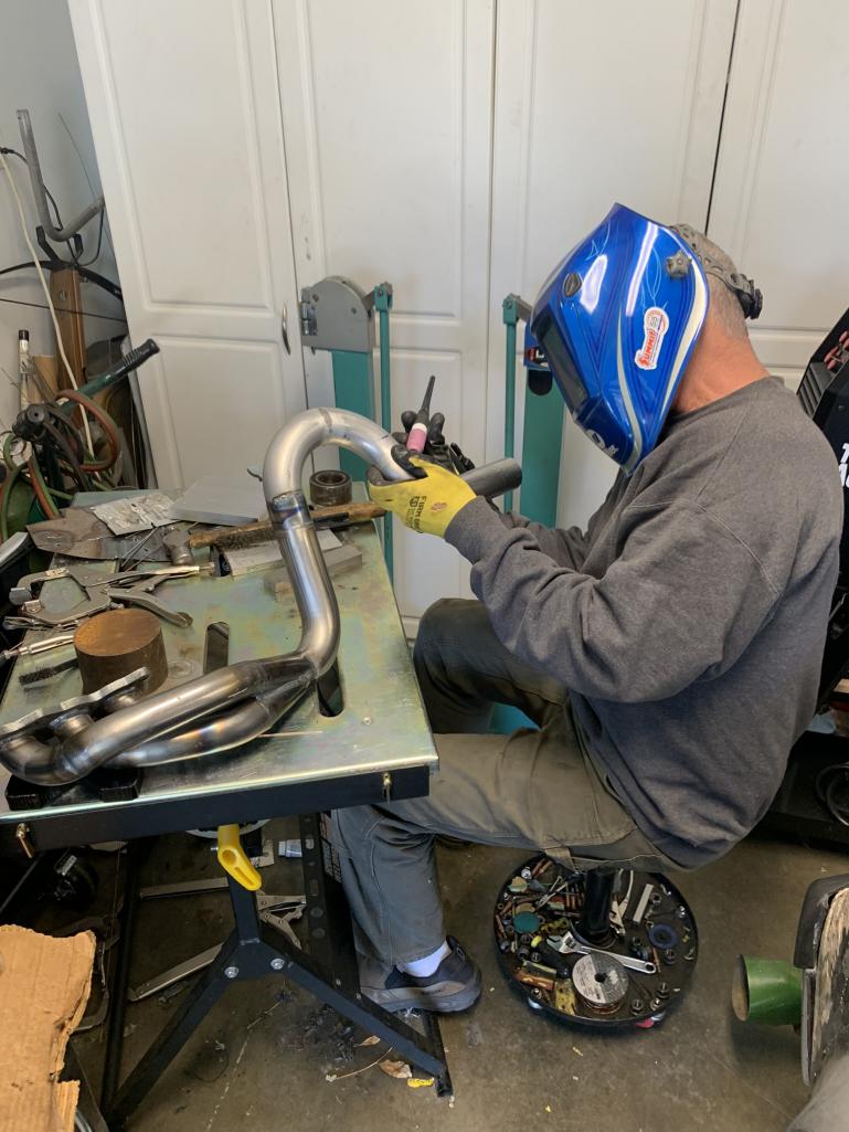
Posted by: Mayne Jul 9 2023, 07:50 AM
Looks great! It seems like it’s designed without any crossover, which I would think simplifies the fabrication. What mufflers are you using?
Posted by: 76-914 Jul 9 2023, 08:42 AM
That is a nice header they make. Did you go with SS or steel? Chris, are you sitting down on the job?
Posted by: rmarx Jul 9 2023, 11:12 AM
Looks great! It seems like it’s designed without any crossover, which I would think simplifies the fabrication. What mufflers are you using?
Just basic 2 1/2 inch turbo style mufflers from Summit.
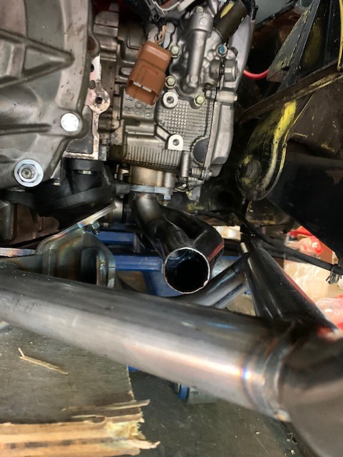
Posted by: rmarx Jul 25 2023, 10:03 PM
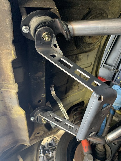
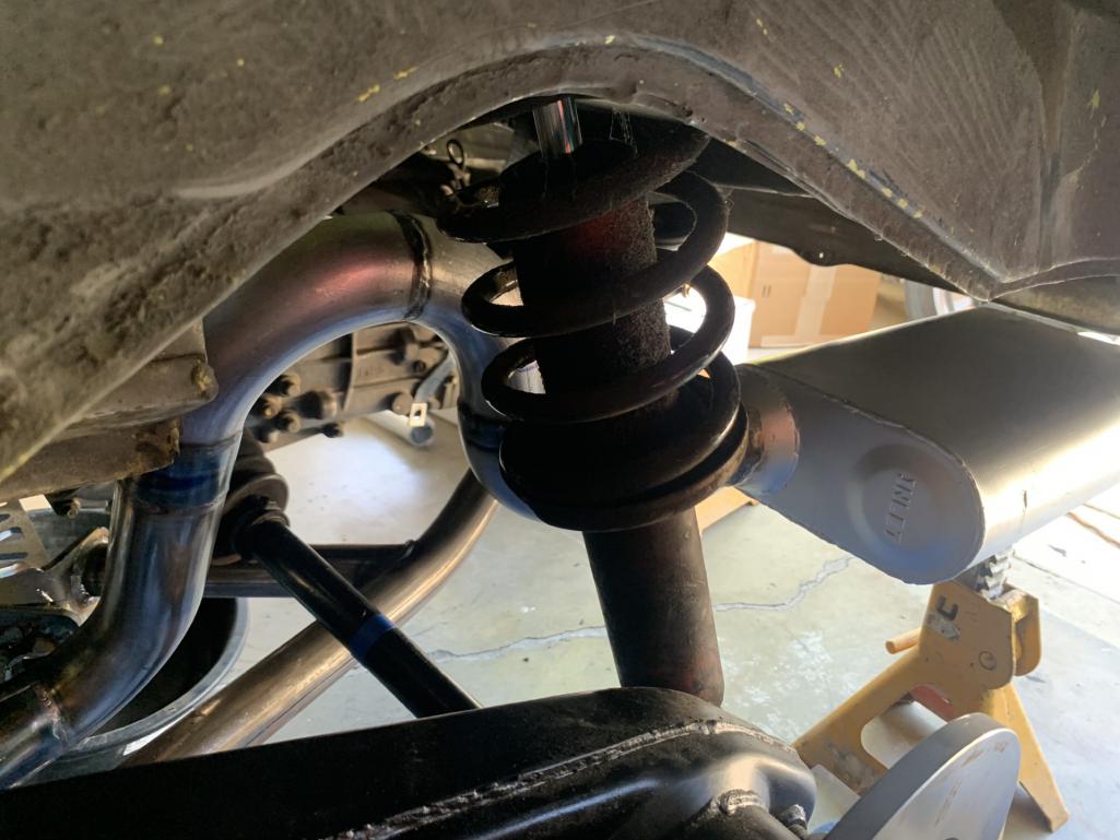
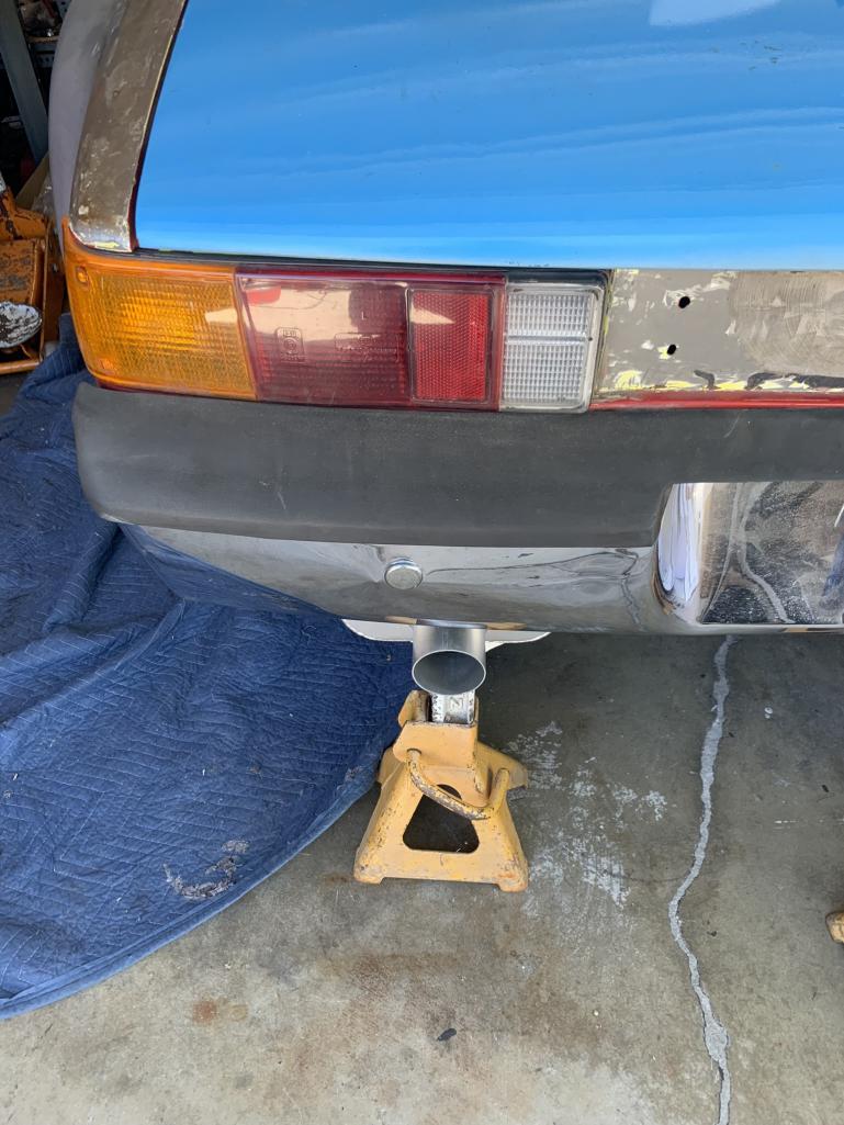
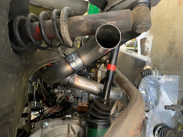
I finshed mounting the left side muffler. I've shown the mounting hardware, clamps and muffler as it looks from the rear.
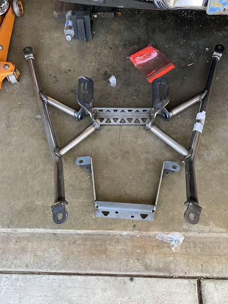
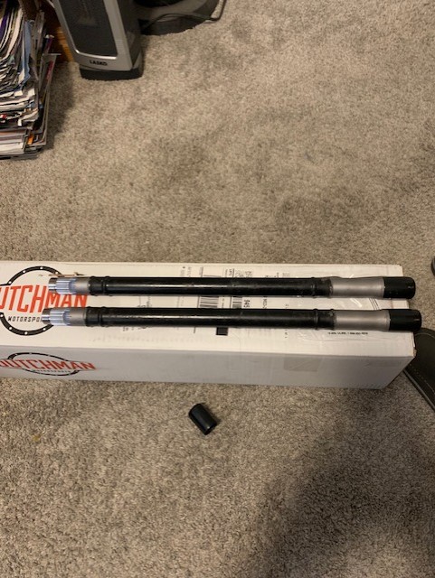
I just received my axles back from Dutchman Motorsports. They did a nice job. They look great. Next job will be to clean and re-pack the Porsche CVs and install them on the axles along with the new Subaru CVs. I sure hope I got the measurement right and that they fit properly.
With a little luck, the next posting will show them mounted on the car.
Attached image(s)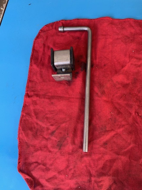
Posted by: tygaboy Jul 25 2023, 11:40 PM
Nice! That mount set up looks like it's gonna work just fine. Can't wait to see it in person.
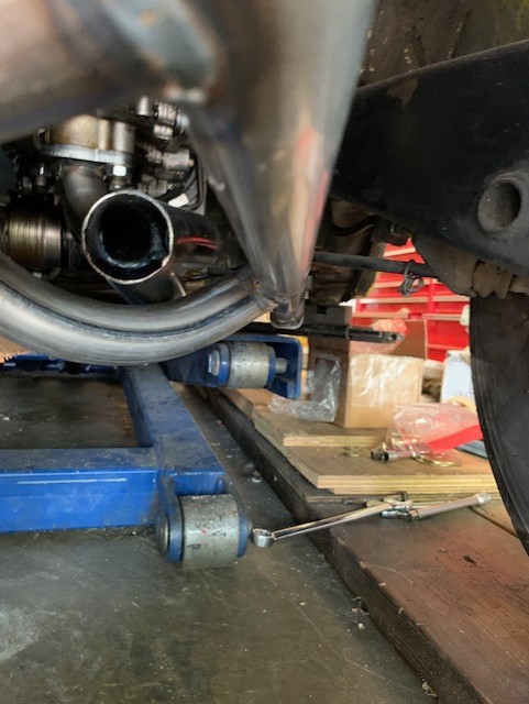
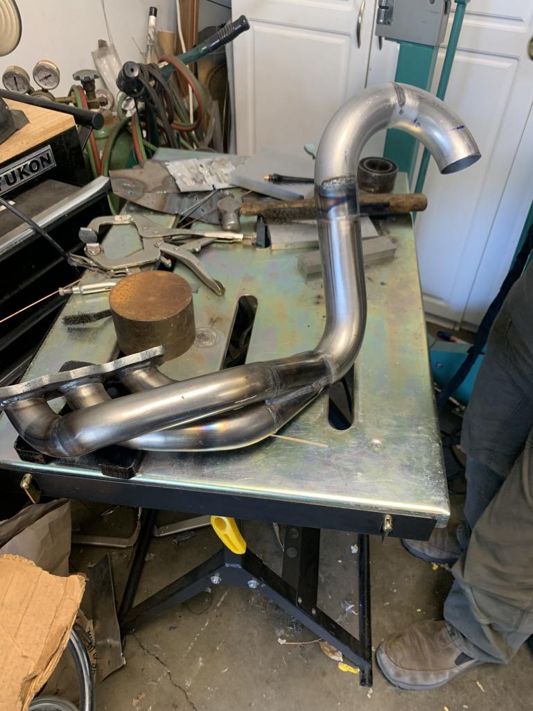
Posted by: rmarx Jul 29 2023, 06:31 PM
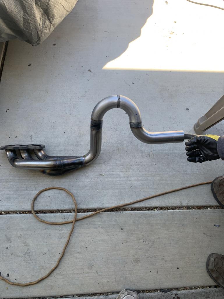
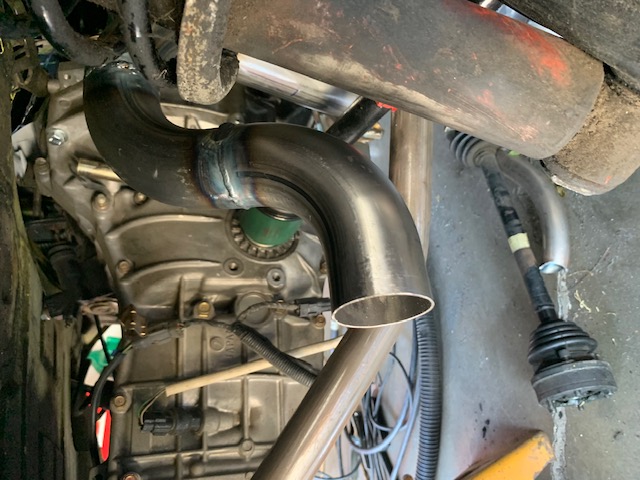
Another well spent Saturday with Chris Baker @http://www.914world.com/bbs2/index.php?showuser=19241 working on my exhaust system.
We, mostly Chris, cut, fit and welded the other side to my exhaust system. I will mount the muffler probably tomorrow. That should compllete the exhaust system except for possibly cera coat or paint, (we shall see).
After finishing the muffler installation, time permitting, I will begin assembling my new axles and test fit them to the car.
Stay tuned...
Attached image(s)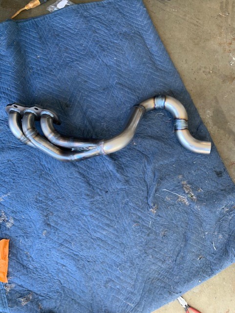
Posted by: rmarx Aug 16 2023, 04:48 PM
Todays lesson is a lesson in frustration.
There is a saying, "You don't know what you don't know".
I sent out a couple of 914 axles to Dutchman to have them cut and resplined on one end to have them mate up with a Subaru CV joint that would attached to the transmission.
They did an excellent job and I am happy with their work.
I installed the 914 CV on one end and a Subaru CV on the other. I installed it on the car and it fit beautifully.
Then I went on to the other axle and this is where the fun started.
I attemted to install the 914 CV on one end to no avail. I thought, "this is strange".
So I called someone who does this kind of work, told them my problem. They told me that sometimes you have to use a hammer to get them on. I thought "OK", I will try that.
NOT!
Don't do that!
I ruined the CV and buggered up my axle.
I then spent a lot of time cleaning up the axle with a needle file and a dremel, but still no luck.
What I then realized is that I tried to put a 914/6 25 spline CV on a 914/4 axle (31 spline).
I will get the correct CV and all should be well.
Just remember, there is a difference. Check out what you have before it's too late.
Posted by: 76-914 Aug 17 2023, 08:48 AM
 happens when you get off the beaten path. I didn't post 80% of the headaches I went through for fear of looking like an idiot. Good to see your attitude remains intact. It's the only thing that will carry you through to the end. Well, that and not wanting to tell the wife how much you spent on a project that defeated you.
  You'll be driving it before you know it and it will all be worth it.
Posted by: tygaboy Aug 17 2023, 09:24 AM
happens when you get off the beaten path. I didn't post 80% of the headaches I went through for fear of looking like an idiot. Good to see your attitude remains intact. It's the only thing that will carry you through to the end. Well, that and not wanting to tell the wife how much you spent on a project that defeated you. You'll be driving it before you know it and it will all be worth it.  w/ @http://www.914world.com/bbs2/index.php?showuser=9964 Kent. And never fear looking like an idiot! Ask me how I know...
 IMO, if you aren't "failing", you aren't learning.
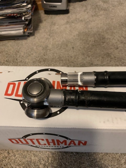
Posted by: rmarx Aug 20 2023, 07:20 PM
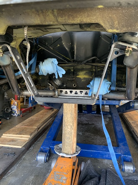
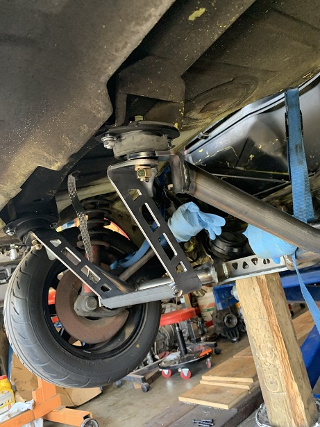
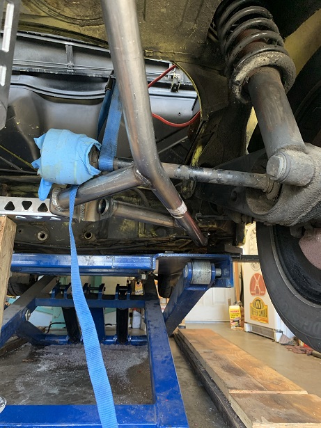
I found the correct 914/4 CV in my parts stash and proceeded to clean it up and re-pack it with grease.
That can be a very frustrating job. While putting it back together, it rotated out of alignment and the large end of the spline piece matched up with the large end of the CV. By the time I got all the ball bearings installed, I realized that it had jammed and would not operate as assembled. After much time to get it apart again, I aligned the parts corrctly and finally got it back together.
I mounted it on the axle and proceeded to mount the CV for the other side which uses a Subaru CV. I got it all together and went to mount it on the car when I realized that the new CV I bought fits the trans, but the inner spline does not fit my axle.
I can't win!
I could not find another Subaru CV locally when I had a thought.
Why don't I take the inner spline from one CV and match it with the outer splined housing from another.
Normally I woudn't mix and match CV parts because of wear, but they are brand new.
It all went together and is now mounted on the car. I will wait to drive it to determine if there are any issues with my remedy.
Attached image(s)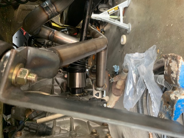
Posted by: 76-914 Aug 20 2023, 08:14 PM
It's probably fine. That broach has three bearings and they are new so it should be fine. I think all of us have had trouble with the Porsche CV the first few times around.
Posted by: tygaboy Aug 20 2023, 09:13 PM
One less thing on the to-do list! Congrats
Posted by: rmarx Nov 25 2023, 06:34 PM
Happy belated Thganksgiving everyone!
It's been awhile since my last post. A lot has occured in that time,
It's time to announce a change in direction.
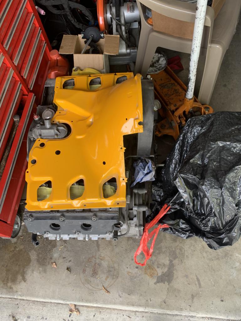
I have decided to move in a different direction and scrap the Subaru conversion and convert the car to a Porsche 914/6.
I have obtailned a fairly newly built 2.7 Ltr engine with "S" cams. I will run it with Weber carbs and a header with a sport exhaust.
I have sold all the Subaru conversion parts and have started to collect the parts neccessary to complete the project.
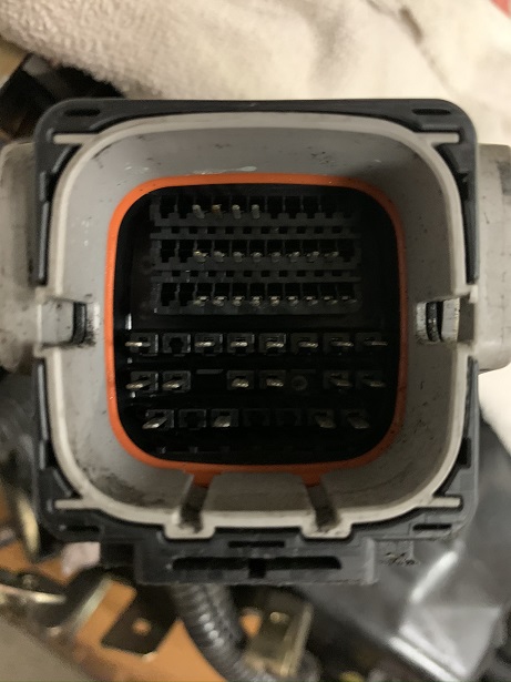
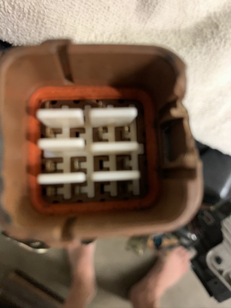
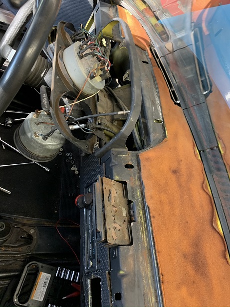
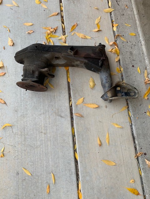
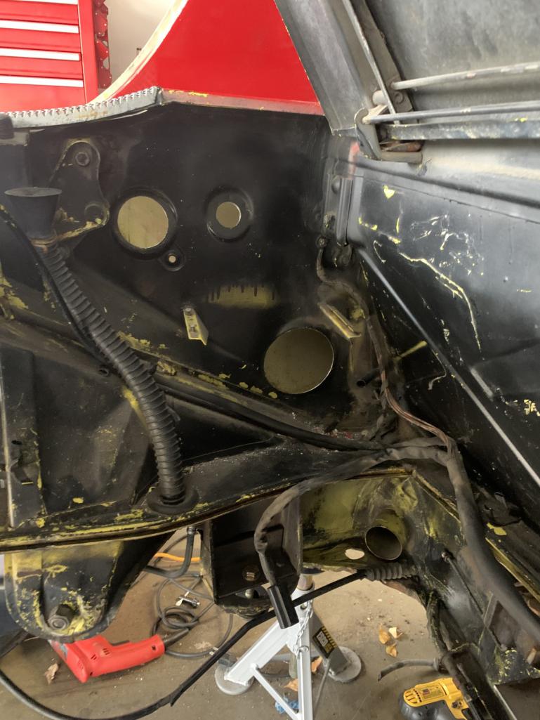
I purchased a Mad Dog engine mount. I am having a little difficulty figuring out how to actually mount it. It does not fit flushly (is that a word?) against the firewall as the thick wiring harness is in the way. It looks like I have to re-rout the harness to fit the mount.
I was wondering what everyone else has done. I'm looking for advise. Thank you in advance.
Attached thumbnail(s)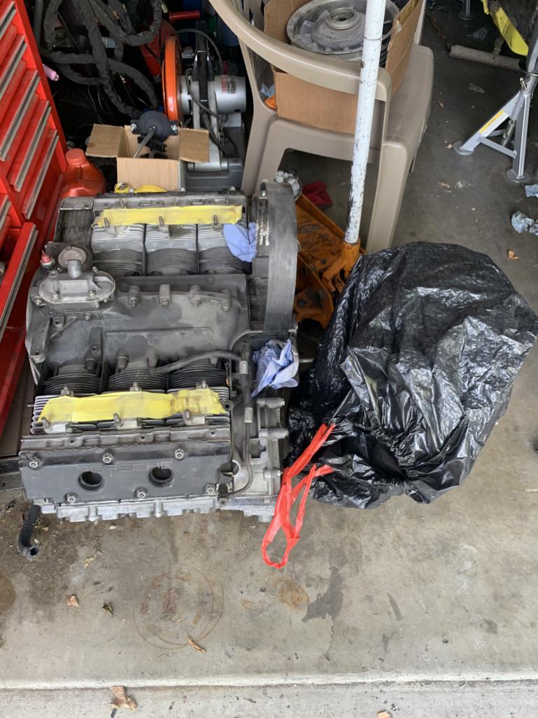
Posted by: tygaboy Nov 26 2023, 10:53 AM
@http://www.914world.com/bbs2/index.php?showuser=9892 Ben (or any of you who may be able to help!) - can you offer any input on Bob's question about needing to re-route the wiring snorkel when fitting the MadDog /6 engine mount?
Posted by: mb911 Nov 26 2023, 11:45 AM
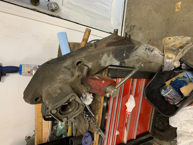
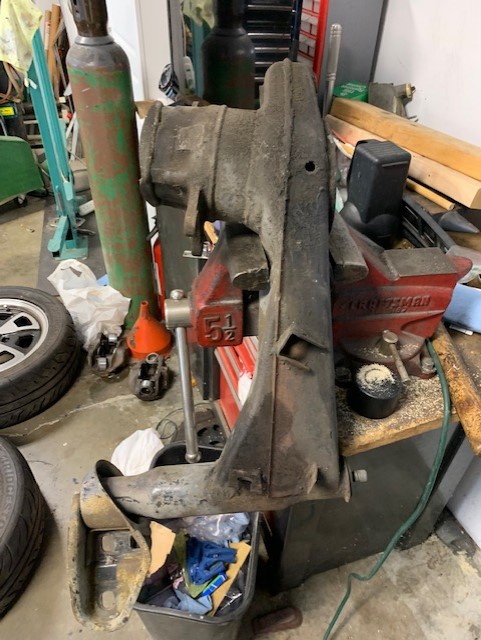
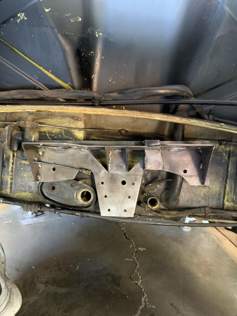
So that mount has to be cut to clear the shift boot attach flange.
Posted by: willieg Nov 26 2023, 11:45 AM
Bob: I know you have a lot of hours into your 914/Subaru build. So, I applaud your decision to scrap that project and do a build you have always wanted to do.
Posted by: mb911 Nov 26 2023, 11:53 AM
Here is an image. Hope this helps.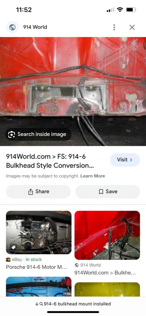
Posted by: tygaboy Nov 26 2023, 12:09 PM
@http://www.914world.com/bbs2/index.php?showuser=9892 - Thanks Ben! That'll help for sure.
Posted by: Mayne Nov 27 2023, 06:47 AM
Re: change to 911 swap: Cool! And you would if you could! It’s hard to see a 911 engine coming my way, so I’ll keep soldiering on with the E30R.
Posted by: rmarx Nov 27 2023, 08:38 PM
Re: change to 911 swap: Cool! And you would if you could! It’s hard to see a 911 engine coming my way, so I’ll keep soldiering on with the E30R.
I think you will be happy with it when you are done. It will certainly be more powerful than the 911 arternative...
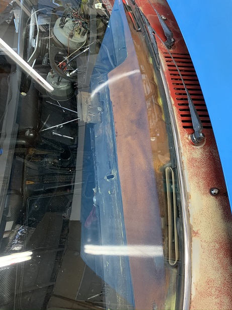
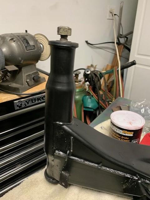
Posted by: rmarx Dec 6 2023, 05:05 PM
What is it about guys and taking directions.
I was having a phone conversation with Ben Mcfarland @http://www.914world.com/bbs2/index.php?showuser=9892 . I'm telling him that I am going to drill the holes on the chassis for the oil tank filler, vent line and filter console.
He tells me to go SLOW, otherwise the drill will catch and rip out of your hand and probably injure you.
Having done this operation before, I naturally said "yea sure, I know what I'm doing".
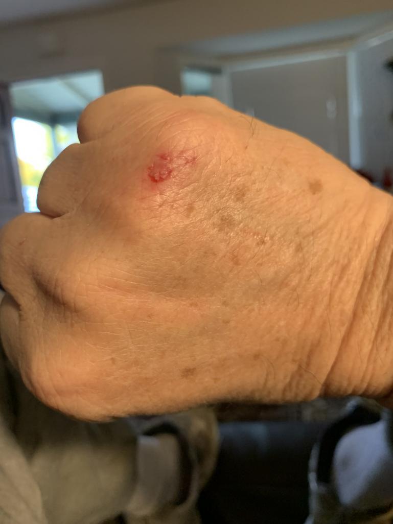
Sure enough, I start slowly, but as it is taking longer than I wanted, I of course increase the speed of the drill to get the job done faster when all of a sudden, the hole saw bites and locks up which caused the drill to rip out of my hand and smack the back of my hand crushing it between the drill and the car.
OUCH!
Believe it or not, I start laughing at my self saying "You Idiot, you know better!"
Luckily, just a little blood, nothing permanant.
The holes are now cut and ready for the tank installation.
The moral of the story, BE PATIENT! Take your time.
Attached thumbnail(s)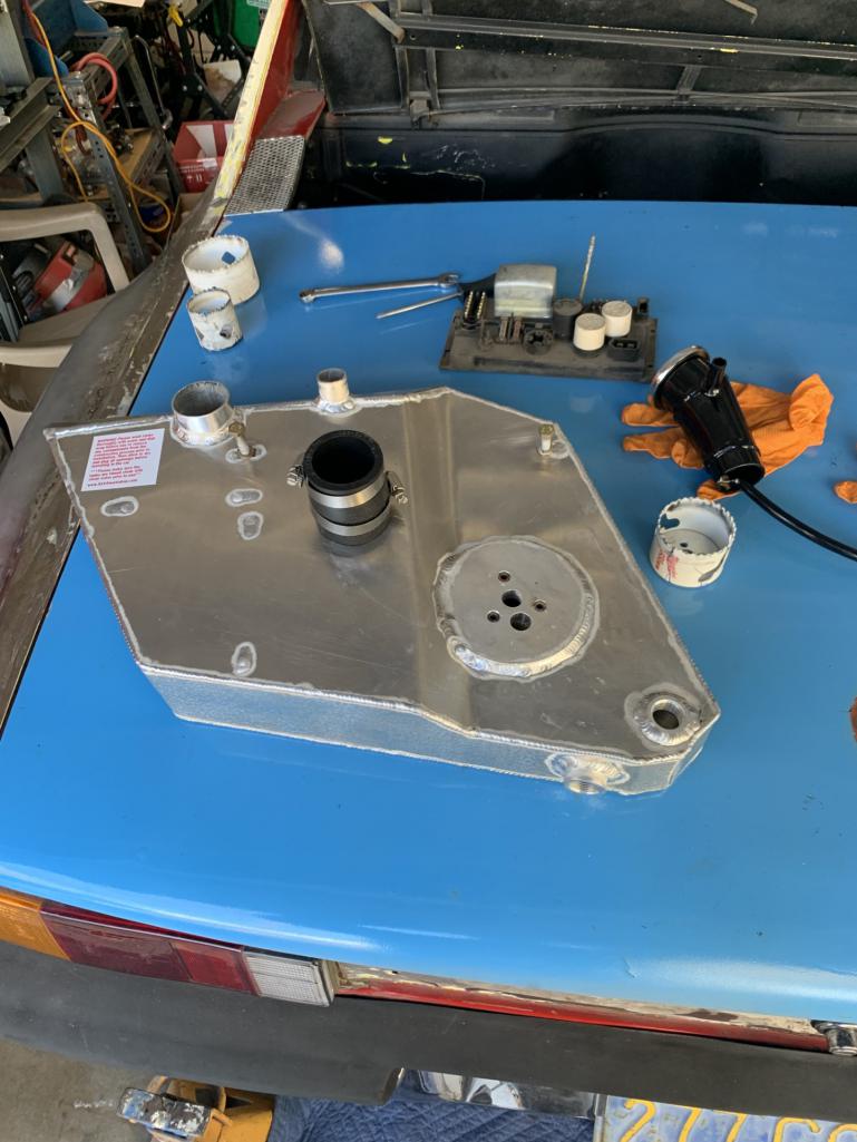
Posted by: Nogoodwithusernames Dec 6 2023, 05:19 PM
What is it about guys and taking directions.
I was having a phone conversation with Ben Mcfarland. I'm telling him that I am going to drill the holes on the chassis for the oil tank filler, vent line and filter console.
He tells me to go SLOW, otherwise the drill will catch and rip out of your hand and probably injure you.
Having done this operation before, I naturally said "yea sure, I know what I'm doing".
Sure enough, I start slowly, but as it is taking longer than I wanted, I of course increase the speed of the drill to get the job done faster when all of a sudden, the hole saw bites and locks up which caused the drill to rip out of my hand and smack the back of my hand crushing it between the drill and the car.
OUCH!
Believe it or not, I start laughing at my self saying "You Idiot, you know better!"
Luckily, just a little blood, nothing permanant.
The holes are now cut and ready for the tank installation.
The moral of the story, BE PATIENT! Take your time.
BTDT, was cutting holes in the top plate of a wall to put a mini split AC system in at our old place. Was an exterior wall by the eaves so tight space, hot, dusty etc. Trying to drill through the two 2x4s and get in a hurry and BAM, drill caught me right on the side of the head. Just laid there in the dust and insulation for a minute after that and slowed it down after that.
Posted by: mb911 Dec 7 2023, 10:04 AM
Robert,
Man I can totally invision the pain. I did chuckle a little reading this but not because you hurt your self but because I have done it myself
Posted by: rmarx Dec 9 2023, 04:11 PM
Having decided to convert the car from a 4 cyl to 6 cyl 911 engine, I thought the next step would be to make a list of all the parts needed to complete the project.
The following is that list:
Engine - 2.7 Ltr
Transmission - 914 Side shifter
Shifter and shifter rods (2), bushings
Engine mount
Oil Tank, lines and fittings
Half shafts with CV joints
Engine sheet metal (to seal engine compartment)
Weber carbs
Intake manifolds and linkage
engine oil cooler (modified for 914 configuration)
engine wiring harness
alternator (my engine did not come with one)
Distributor, cap and wires
3 pin CDI box
Clutch pedal return spring ( I removed mine during the Subaru conversion)
Many of these parts I have already obtained. I will be posting updates and progress pictures as we go.
I might also post requests for parts I do not have.
Stay tuned
Powered by Invision Power Board (http://www.invisionboard.com)
© Invision Power Services (http://www.invisionpower.com)