Printable Version of Topic
Click here to view this topic in its original format
914World.com _ 914World Garage _ Going to Megasquirt
Posted by: bbrock Sep 11 2021, 10:46 AM
After about 1,700 miles of driving my freshly restored car with rebuilt engine, I’ve decided I’ve had my fun with Weber carbs and distributor-based ignition and am ready to step up to modern EFI and coil on plug ignition. Even with the jetting that came out of the box leaving the carbs running rich, the performance has been fantastic. What is not fantastic is the garage stinking of gasoline, no compensation for altitude, and being generally too fiddly to set up for my taste. My trials with the ignition are documented in another thread. Yes, I know a 1-2-3 would solve those problems but for the money, I’d rather invest in modern COP ignition as part of an EFI upgrade.
My goal is a smooth, efficient, and reliable street machine that I can drive from sea level to 11,000 ft. without starving or choking on fuel. Efficiency is at least as important as performance. As long as I can get at least the stockish 100 hp, I’ll be happy and beyond that, I’d like to wring as many mpg out as possible.
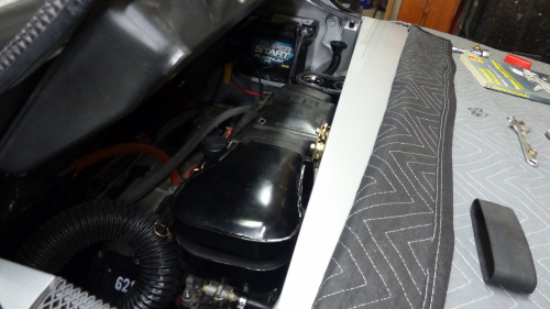
The engine is a mostly stock euro-spec 2L engine. The only mod is a fairly mild Elgin 6048 camshaft with 256 duration for the carbs. A source of pride of this build is this custom 911/914-6 inspired air cleaner I made which I think looks cool and really silences the carbs.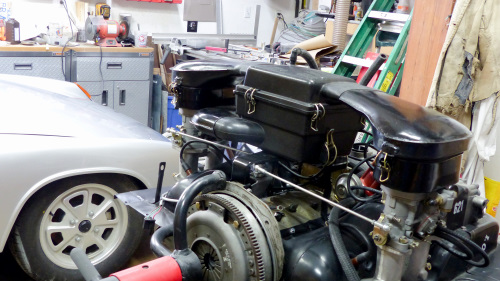
Now for the questions:
• Single throttle body or ITB? I think I’ve made a decision but still interested in thoughts. I was thinking about welding injector bungs onto the carb manifolds and using my carbs as throttle bodies. The main appeal is that I would keep my cool air cleaner to make the other kids jealous. However, it seems the stock throttle body would greatly simplify the conversion. Also, even though the custom intake is designed to allow access for servicing and easy air filter replacement, it does crowd an already crowded engine bay and makes working in there just that much more of a challenge. My stock TB needs some TLC and might have to be sent for professional refurbishing. I think I could sell my carb setup to cover that cost but not sure. The upshot is that I’ve all but decided to go back to the stock TB, but curious what others think.
• N Alpha, Speed Density, or MAF? I’ve been reading up on this and think I understand pros and cons, but still a little confused about sensors needed. With my efficiency goal, I think MAF is the way to go. It looks to me that cutting off the tube connecting the stock air cleaner to the TB and replacing it with a MAF could be a really slick way to add MAF in stealth fashion. Has anyone done this? If not, how does one find the right MAF to use? Other than dimensions, what else needs to be considered?
Another question is about MAP + MAF vs MAF only. I’m a little confused about advantages or when a MAP sensor is needed if you have a MAF.
• Barometric correction – this is an important feature for my location, but the hardware needed to implement it is a little confusing. It seems like if you are running a MAP, then barometric correction is obtained by adding a second pressure sensor (another MAP?) to read reference atmospheric pressure to make corrections to the fuel mixture. How does it work with MAF? Do you only need one pressure sensor to read atmosphere? Or do you still need to reference it against manifold pressure? I assume a lot of this is done in the software but I haven’t looked to far into the tuning part yet. I’m more trying to figure out a shopping list for parts at this point.
• Anyone running a CAM sync and sequential spark and injection? Again with the efficiency goal, this is appealing. Looks like Mario is working on a new version which isn’t available yet, are there alternatives available? It seems people say you still need a crank position sensor even with a cam sensor in the mix. It isn’t entirely clear why though. Lastly, and this is mostly just curiosity, but is it correct to think that the lifespan (in miles) of spark plugs are cut in half with wasted spark?
I have many more questions but this is already too long so will save them for later.
TIA
Posted by: BeatNavy Sep 11 2021, 01:43 PM
Brent, you'll enjoy the challenge and learning associated with Microsquirt. And knowing your abilities, you'll have it running like a top quickly. I wish I could do justice to your very specific questions, but I simply don't have the breadth of experience with MS. I'm not sure how many of us here do. I think most of us using MS have it running for our specific application, but there's probably at least a few here that have knowledge that is both broad and deep enough to comment intelligently.
Random (unintelligent) thoughts WRT your questions (that you probably already know):
ITB's are going to be harder than stock TB for getting a good signal for speed density/MAP (or MAF, I would think, although I have no experience with MAF). You almost have to go Alpha N at that point. Alpha N can work from my experience. I've run both Alpha N and speed density on my stock TB setup, and they both provide slightly different experience across the driving spectrum. What's nice is it's easy to go back to one or the other. Part of the reason I swapped back and forth was trying to get my Raby 9950 cam to hold a better cold start idle, and my AFR numbers at idle were highly suspect with the exhaust I had at the time. Your ultimate setup may depend on the characteristics of your specific cam. FWIW, I'm running pure speed density for the time being.
I would think you could meet your stock HP and efficiency goals without any problem. Having said that, it seems (to me at least) that simply putting MS on a Type 4 won't easily trump what those crafty Porsche engineers did with analog/primitive D-Jet (or L-Jet) back in the day. In other words, maximizing what you can get out of the Type 4 is a bit of an art, IMO. The strength of MS is you have the ability to perform finer adjustments, get better feedback data, and do situational tuning (e.g., the ability to have a 'max efficiency tune' or a 'max power' tune that you can swap out with a click of a button).
From my understanding wasted spark (which I run) can have an impact on plug service life, but it should be a small impact if the correct plugs are used (e.g., those with platinum).
Have you joined the MS forum yet?
Some of these questions may best be asked there:
https://www.msextra.com/forums/viewforum.php?f=134&sid=4e2c93b31757ab9f5bf40220c725d0db
Posted by: Morph914 Sep 11 2021, 02:13 PM
Brent, I will be watching this closely as I may switch over as well. I have been taking a break through the hot humid weather as it is too hot to work in my shop. If I can’t get the d-jet dialed in properly, I’m going to switch over.

Cheers,
John
Posted by: Chris914n6 Sep 11 2021, 02:44 PM
I'd run Speeduino over MS as it's a newer design with newer hardware. The software is the same, TunerStudio.
I'd pick a factory system to steal parts from, like a Miata, that is already in the software. MAF for driveability.
You can keep the carbs as itb as it connects to the same plenum for the maf. Most itbs don't run thru a plenum thus no maf.
Posted by: Superhawk996 Sep 11 2021, 03:10 PM
Just sayin' . . . .
https://thedubshop.com/dual-throttle-body-fuel-injection-package-with-ignition-type-4/
Mario has great reviews and he now has a dyno!
Should work with your air cleaner with minimal mods. Don't screw with trying to make your carbs into ITB's.

Posted by: r_towle Sep 11 2021, 03:22 PM
Buy ITBs that look like carbs
Buy manifolds with injector ports
Go vdub route for the rest, it’s been done a lot
Cbperformance has all the hard parts
Yah, go for a kit like what was posted above!!!
Posted by: JamesM Sep 11 2021, 04:30 PM
Throttle Body? Given you already have the cool airbox setup and the manifolds and linkage, and not knowing how your cam will react with a shared plenum intake, I would just pick up a set of ITBs.
Fueling Algorithm? This is going to depend on if you decide to go with a single throttle body or ITBs as well as well as what sort of vacuum your cam produces. Also the MSExtra firmware (that you will want to run) has additional fueling algorithms that I would recommend over the above mentioned. Single throttle body you are most likely going to want to use "% Baro" which is basically speed density scaled to your current altitude. ITBs if your vacuum signature allows I would recommend "% baro" but with ITBs it usually wont, in which case I would run "hybrid Alpha-n" which is somewhat more difficult to initially tune but gives you the best of both worlds.
Barometric correction is always applied however i believe what you are looking for is "Real time Barometric correction" which requires a 2nd MAP sensor if you are using the 1st MAP sensor for your fueling. With a single MAP sensor the MS takes a barometric reading before you start your engine and uses that for the entire run time so if you have a drastic change in altitude over your drive your fueling will be off. Adding a 2nd sensor allows it to get a constant baro metric reading. This is a really easy thing to add when building your harness.
My thoughts on CAM sync and sequential injection are that it is really overkill for these cars. The impact of it is extremally minimal and only makes a slight difference to emissions at lower RPMs as at higher RPMs the injection time required means you will always be squirting on to a closed valve anyways. It does add a lot more complexity to the build and tune though, which is already going to be a steep learning curve if you have never done this before.
Plug life with wasted spark? That all depends on what you are referring to as wasted spark. An actual wasted spark coil pack where 1/2 of your cylinders get fired with reversed polarity has the potential to more than double the wear on the 2 plugs that get fired in reverse, especially if you run stock plugs. This was one of the reasons for some of the exotic metal plantings they stared putting on the electrodes. You can run coil per plug or a 4 coil pack in 2 channel batch fire which is the same as wasted spark in that you have a wasted spark, however all 4 coils still fire with standard polarity so you dont get that extra plug erosion.
Posted by: 930cabman Sep 11 2021, 04:44 PM

Throttle Body? Given you already have the cool airbox setup and the manifolds and linkage, and not knowing how your cam will react with a shared plenum intake, I would just pick up a set of ITBs.
Fueling Algorithm? This is going to depend on if you decide to go with a single throttle body or ITBs as well as well as what sort of vacuum your cam produces. Also the MSExtra firmware (that you will want to run) has additional fueling algorithms that I would recommend over the above mentioned. Single throttle body you are most likely going to want to use "% Baro" which is basically speed density scaled to your current altitude. ITBs if your vacuum signature allows I would recommend "% baro" but with ITBs it usually wont, in which case I would run "hybrid Alpha-n" which is somewhat more difficult to initially tune but gives you the best of both worlds.
Barometric correction is always applied however i believe what you are looking for is "Real time Barometric correction" which requires a 2nd MAP sensor if you are using the 1st MAP sensor for your fueling. With a single MAP sensor the MS takes a barometric reading before you start your engine and uses that for the entire run time so if you have a drastic change in altitude over your drive your fueling will be off. Adding a 2nd sensor allows it to get a constant baro metric reading. This is a really easy thing to add when building your harness.
My thoughts on CAM sync and sequential injection are that it is really overkill for these cars. The impact of it is extremally minimal and only makes a slight difference to emissions at lower RPMs as at higher RPMs the injection time required means you will always be squirting on to a closed valve anyways. It does add a lot more complexity to the build and tune though, which is already going to be a steep learning curve if you have never done this before.
Plug life with wasted spark? That all depends on what you are referring to as wasted spark. An actual wasted spark coil pack where 1/2 of your cylinders get fired with reversed polarity has the potential to more than double the wear on the 2 plugs that get fired in reverse, especially if you run stock plugs. This was one of the reasons for some of the exotic metal plantings they stared putting on the electrodes. You can run coil per plug or a 4 coil pack in 2 channel batch fire which is the same as wasted spark in that you have a wasted spark, however all 4 coils still fire with standard polarity so you dont get that extra plug erosion.
Looks awfully confusing. Is the Weber setup that bad?
Posted by: JamesM Sep 11 2021, 04:53 PM
I'd run Speeduino over MS as it's a newer design with newer hardware. The software is the same, TunerStudio.
I'd pick a factory system to steal parts from, like a Miata, that is already in the software. MAF for driveability.
You can keep the carbs as itb as it connects to the same plenum for the maf. Most itbs don't run thru a plenum thus no maf.
I probably wouldn't
Zero advantages but plenty of reasons not to
Megasquirt has a lot more development and people running it.
The Speeduino hardware isnt really any newer, sure the original megasquirt has been around MUCH longer (which is a good thing) but the hardware and software are both constantly being updated. The MS system I run today is 100% different than the MS system I was running in 2005.
Speeduino was/is just a project to do basically the same thing as MS but using an Arduino as its core. While MS systems were designed specifically to be fuel injection systems the Arduino was not, its just a generic tinkering/project platform that someone decided to build an injection system with, probably to avoid the Megasquirt licensing. Not sure if any of the components on the Arduino itself are even automotive grade, let alone able to survive an 914 engine bay.
There are ecu options other than megasquirt/microsquirt you could go with, not sure i would do Speeduino though.
Posted by: JamesM Sep 11 2021, 04:56 PM
Looks awfully confusing. Is the Weber setup that bad?
The difference between a d-jet setup and a GOOD megasquirt(or any programable EFI) install is night and day.
The difference between webers and a GOOD megasquirt install will absolutely blow your mind.
Notice i emphasized GOOD. Its a steep learning curve and there are a lot of ways to screw it up.
Posted by: Montreal914 Sep 11 2021, 05:02 PM
Will follow this thread with great interest. ![popcorn[1].gif](style_emoticons/default/popcorn[1].gif)
I had to pause my MS conversion because I decided to pretty much redo the whole car...  Things are moving along but it is quite an undertake as you obviously know.
Very nice intake setup BTW. My understanding is that ITBs are more of a challenge, but it would be sad not to use your nice design!
Good luck!
Posted by: GregAmy Sep 11 2021, 06:03 PM
I go to all the trouble to write this stuff up...
https://tgadrivel.blogspot.com/2020/03/on-microsquirting-porsche-914-part-1.html
Posted by: bbrock Sep 11 2021, 06:41 PM
I go to all the trouble to write this stuff up...
https://tgadrivel.blogspot.com/2020/03/on-microsquirting-porsche-914-part-1.html
And I have read ALL of it! In fact, I blame you and your blog for getting me into this trouble
Thanks everyone for all the feedback so far. A lot of great stuff to ponder.
I'm surprised by the discussion on ITBs. I really though the overwhelming advice would be to ditch the fancy air cleaner and use the stock TB. So let's talk about this a little more. My second stop on this journey (after Greg's blog) was looking at the Dub Shop kits. It didn't take long to rule those out. Yes, the ITBs are sweet but are as expensive as a set of carbs and more than I think I could sell my carbs for. Also, I cannot assume they would be compatible with my air cleaner. Yes, the ITBs are the same dimensions as 40IDFs so no issue there, but what about the manifolds? If they are as much as a half inch different and total height than mine, then the geometry of the cleaner intakes will be off and they won't fit correctly. To me, if I went the ITB route, it makes more sense to just use the carbs as throttle bodies. Others have done it. Why would that be a problem. It would eliminate a major expense.
As for the cleaner. To be honest, that was a personal challenge. I'm very proud of that cleaner, but now I've done it and won't cry if I pass it on to someone else to enjoy. Working in the engine bay will be a little easier with the stock TB and cleaner setup. Then again, the point of doing this is to greatly reduce the need to work in the engine bay.
WRT vacuum signal. I guess I should measure what I have. All I can say now is that I'm getting good enough signal from a single barrel to actuate my vacuum advance (port vacuum) and retard (manifold vacuum). My cam is pretty mild. Basically stock lift with a bit longer duration. Enough that it would run rough with D-Jet which is why I'm not just refurbing the D-Jet system. I don't have an appetite to split the case on a freshly rebuilt and running well engine to swap cams.
So the real question WRT ITBs is, what advantage do they bring other than looking cool and letting me keep the cool air cleaner? Honestly, I need more than that. I imagine they provide significant advantages in big displacement engines, but would they do anything meaningful for my little hundred pony power plant?
Re: barometric correction - Yes, I'm talking about real time correction. Where I live, I can easily drive through 8000 ft. of elevation change on a single tank of gas. I'd like to be able to cruise over high mountain passes without missing a beat.
WRT if the Weber setup is that bad. In a word - yes. I would say I hate them. Just the stench of gasoline in the garage they cause is enough to get rid of them. I have 3 fuel injected cars dating back to MY 1991 with a combined total of nearly a million miles on them. All of them have performed flawlessly through those miles. Starting in all conditions, running well at all elevations and temperatures, and all that with zero tune-ups among the 3 of them. I want that for the 914.
Posted by: bkrantz Sep 11 2021, 07:21 PM
Brent, welcome to the club. You may make progress faster than me, since my Dubshop kit is still in boxes.
Posted by: bbrock Sep 11 2021, 08:15 PM
Brent, welcome to the club. You may make progress faster than me, since my Dubshop kit is still in boxes.
Ha ha. You have no idea how jealous I was when I saw that kit on your thread!
A couple more questions:
I know a lot of people set up Microsquirt only without adding ignition control. I assume, but am not sure, that it could be done in reverse. I'd like to convert my my ignition to MS controlled COP first, and once that is running, turn to fuel management. Any problem doing it that way?
Also, I've seen some cool installs that hide the MS ECU and Lambda controller inside a stock D-Jet ECU box. Anyone who has done that care to share how it has worked? It doesn't exactly comply with recommendations for mounting either unit but has a lot of appeal to me and I don't see why it wouldn't work.
Oh, and Rob asked if I've joined the MS forum yet. The answer is no, but I've stalked it quite a bit. I'll join as I get closer but thought I'd start here with the fine folks with 914 specific experience first. And thanks for your vote of confidence. Someday we may meet in person and you will realize how misguided it is

Posted by: Montreal914 Sep 11 2021, 08:59 PM
In case you haven't seen/read my partial adventure, enjoy!
http://www.914world.com/bbs2/index.php?showtopic=342361&st=60
That being said, it stands today exactly where I stopped on the last post because I started to rebuild the whole car. I am looking forward getting back to this as rust repair isn't really appealing to me...
So, although there might be a good portion of the setup in place, nothings has really been tried. 
Posted by: JamesM Sep 12 2021, 12:18 AM
Mario at the dubshop makes some awesome parts and kits, but some of the parts he supplies (specifically ITBs) are sourced from other vendors and available cheaper, at least they were last time I looked. Using your carbs as throttle bodies is totally acceptable, it just requires some custom fabrication as no one makes manifolds with injector ports. Reasons I suggested ITBs over the stock d-jet intake is that your cam is a bit of an unknown, you already have most of the parts to do it along with that cool airbox, and its likely that going from 4 throttle plates down to 1 you are going to loose some throttle response which some people may not like and may interpret as a loss of power (though you may wind up gaining some midrange torque). Great thing about aftermarket injection though is that if you build your wiring harness with enough slack to accommodate either configuration you could easily swap between either intake setup down the line. If you already have the 2.0 intake bits by all means go for it, it will be less work and less complicated to tune. No harm and easy enough to swap later if you like.
Advantages of ITBs? Better throttle response. They can be a work around if your single plenum design isnt compatible/ideal for your engine config. This is a pretty in depth subject so ill let you google it rather than get into it here. Also they definitely can allow for more flow than the stock intake IF your motor needs it, but it sounds like yours may not. They have some potential disadvantages as well, may loose some drivability, especially if they are not sized correctly, may loose the ability to run speed density, possible loss of some low/mid range torque, more difficult to tune, more complicated linkage, having to get them synced.
Thanks everyone for all the feedback so far. A lot of great stuff to ponder.
I'm surprised by the discussion on ITBs. I really though the overwhelming advice would be to ditch the fancy air cleaner and use the stock TB. So let's talk about this a little more. My second stop on this journey (after Greg's blog) was looking at the Dub Shop kits. It didn't take long to rule those out. Yes, the ITBs are sweet but are as expensive as a set of carbs and more than I think I could sell my carbs for. Also, I cannot assume they would be compatible with my air cleaner. Yes, the ITBs are the same dimensions as 40IDFs so no issue there, but what about the manifolds? If they are as much as a half inch different and total height than mine, then the geometry of the cleaner intakes will be off and they won't fit correctly. To me, if I went the ITB route, it makes more sense to just use the carbs as throttle bodies. Others have done it. Why would that be a problem. It would eliminate a major expense.
As for the cleaner. To be honest, that was a personal challenge. I'm very proud of that cleaner, but now I've done it and won't cry if I pass it on to someone else to enjoy. Working in the engine bay will be a little easier with the stock TB and cleaner setup. Then again, the point of doing this is to greatly reduce the need to work in the engine bay.
WRT vacuum signal. I guess I should measure what I have. All I can say now is that I'm getting good enough signal from a single barrel to actuate my vacuum advance (port vacuum) and retard (manifold vacuum). My cam is pretty mild. Basically stock lift with a bit longer duration. Enough that it would run rough with D-Jet which is why I'm not just refurbing the D-Jet system. I don't have an appetite to split the case on a freshly rebuilt and running well engine to swap cams.
So the real question WRT ITBs is, what advantage do they bring other than looking cool and letting me keep the cool air cleaner? Honestly, I need more than that. I imagine they provide significant advantages in big displacement engines, but would they do anything meaningful for my little hundred pony power plant?
Re: barometric correction - Yes, I'm talking about real time correction. Where I live, I can easily drive through 8000 ft. of elevation change on a single tank of gas. I'd like to be able to cruise over high mountain passes without missing a beat.
WRT if the Weber setup is that bad. In a word - yes. I would say I hate them. Just the stench of gasoline in the garage they cause is enough to get rid of them. I have 3 fuel injected cars dating back to MY 1991 with a combined total of nearly a million miles on them. All of them have performed flawlessly through those miles. Starting in all conditions, running well at all elevations and temperatures, and all that with zero tune-ups among the 3 of them. I want that for the 914.
Posted by: moto914 Sep 12 2021, 08:47 AM
Hi. Running Microsquirt with ITBs here.
The knowledge that gets shared on this site is fantastic. Thanks ! Personally embarked on the MS path for the learning process and a mindset that it wouldn't necessarily add power. The experience has been fine
Your airbox looks great. Was really thirsty for that kind of setup before running ITBs.
You could offsett expenses If you made one that can be fit the standard dual carb manifolds.
There may be buyers.
My setup started with monitoring only.
Posted by: GregAmy Sep 12 2021, 09:57 AM

ITBs are airflow. You'll flow more air with four 40mm(?) bores than with a single 55mm(?), though one can legit argue only one hole is pulling through the stock TB at a time...and as noted above the shorter run gives you throttle response.
I will also note that I'm not seeing a significant drop in manifold pressure as the car revs to redline, so I'm pretty sure the stock setup is not a big restriction. FAT 2056cc with a FAT fuel injection cam.
I've been mulling the idea of replacing my 40DRLAs on the historics race car with Mario's setup, but $$$ and time have allowed me to procrastinate. Plus I'd have to re-do my fuel system (it's single feed line, not recirc) and I'd have to install a voltage manager (I don't run an alternator). But I think it would make for a better race car.
I would not be surprised if you can use your air cleaner with Mario's system; he's using CB Performance throttle bodies which I'm pretty sure are based on Weber IDF carb bodies. Uses the same manifolds, IIRC.
GA
Posted by: bbrock Sep 12 2021, 10:49 AM
@http://www.914world.com/bbs2/index.php?showuser=12023 Thanks for that link! I remember reading it before and thinking it was interesting, but didn't understand most of it. Now I can see the wealth of info there and will be referencing it often!
@http://www.914world.com/bbs2/index.php?showuser=5834
Thanks again for sharing your knowledge. I do enjoy the crisp throttle response I am getting with the carbs and stock dizzy with vacuum advance. It's been too long since I've driven a 914 with D-Jet to compare though. Definitely something to consider.
I've also done more reading about MAF and unfortunately have concluded it isn't feasible for me. A big plus of heated wire MAF is that it measures air density directly so compensation for temperature and elevation changes are automatically embedded in the measurement. The problem is placement to get laminar flow of filtered air through the sensor. I found a good article that says that ideally you want a length of straight, smooth intake at least 5x the diameter of the sensor on both sides. There are screen and honeycomb diffusers to shorten those requirements but the idea of replacing the connector between the stock air cleaner and TB won't work even with diffusers due to being right next to the throttle plate. Likewise, I could mod the intake snorkel on my air cleaner to accept a MAF, but I think the sensor would get contaminated rather quickly with unfiltered air - especially considering the 3 miles of gravel road between my house and pavement.
I'm not giving up on MAF yet, but it is looking like speed density will be the preferred metering strategy which brings up manifold vacuum signal. Is there a number I should be looking for? Like I said, I get enough manifold signal from a single carb throat to pull the vacuum retard diaphragm in and have the tubes to add ports on the other side or even all 4 throats if needed. I'll measure the vacuum I'm getting now but it would be helpful to have a target.
@http://www.914world.com/bbs2/index.php?showuser=20878
Thanks for the compliment. IFAIK there is no standard for carb manifolds for the 914 but could be wrong. I've seen tall and short manifolds and it looks to me like total height dimensions could vary by manufacturer. Mine are what was sold in the old Weltmeister kits way back in the 20th century. The issue is that the center air box mounting height needs to be matched so the intakes mate squarely with the carb housings. Changing the airbox or carb heights relative to each other but much more than a quarter inch changes the angle and creates gaps. Now it could be that my manifolds are the same height as many that are commonly sold now - I just don't know.
Here's a video I posted some time ago with more detail on the air cleaner. The comment I make in the vid about fitting under the rain tray was foreshadowing. It did NOT fit and required going back in and chopping down the bracket holding the air box about an inch and reworking the intakes to restore the proper fit.
https://www.youtube.com/watch?v=Xm-LOk_IBpg
Posted by: Montreal914 Sep 12 2021, 12:25 PM
For ITBs, you have probably read that some people have all 4 vacuum ports on the manifolds connected to a small plenum box, then a line from that box to the modern MPS.
Also, there are 3 typical "GM" MPS pressure available: 1, 2, and 3psi if I recall. All can be used but I believe 1 psi will be more accurate, but I am all going from memory here, so I might be completely off... I am sure the real knowledgeable guys will comment. 
As others have posted before, you can find all sorts of China made IDF style ITBs and other TBs here:
https://www.aliexpress.com/wholesale?catId=0&initiative_id=SB_20210912101829&isPremium=y&SearchText=idf+throttle+body
Posted by: bbrock Sep 13 2021, 08:26 AM
Good to know about the MAP sensors. Looks like most megasquirt oriented sites only sell the 3 bar version so will look at where you sourced yours.
I've made a couple decisions:
- I'm going to follow @http://www.914world.com/bbs2/index.php?showuser=5834 's idea and use the stock throttle body setup but build the harness to be able to work with ITB if I don't like the throttle response with the stock setup. Buying ITBs for this project doesn't make sense because even the cheaper ones look like will cost more than I could get for my carbs. Doesn't pencil out given my carbs would make fine throttle bodies. However, the stock setup will not only be easier, but I could then sell my entire carb setup with air cleaner to recoup a nice chunk of the EFI setup. I'm pretty sure the stock throttle body will be fine with my stock 1971cc build.
- I am going ahead with my plan to add a CAM sync and run sequential spark and injection. There are a couple reasons. One is that once this is running well, I'd like to try iridium plugs which should last longer than I'll have the car - thus eliminating another maintenance item. They are fairly spendy though and doubling their life by sparking only on compression stroke would pay for the CAM sensor. Second, reading the articles linked in Greg's blog about sequential injection convinced me it is the right way to go for my project. Remember that efficiency and emissions are AT LEAST as important to me as performance. I know that's kind of a foreign concept on this forum Getting better fuel economy and drive ability around town will be worth the expense and slightly added complexity to me. I want to bring this system into the 21st century, not just the late 20th. Looking back at the old mileage records for this car in stock (although well-worn) condition, I was getting great highway mileage but pretty poor city mileage. It will be interesting to see what I get with this upgrade. Unfortunately, it looks like that means going to Megasquirt 3 which adds another $200, although I saw there is a daughter board for Microsquirt I need to learn more about.
Posted by: GregAmy Sep 13 2021, 10:28 AM
Good to know about the MAP sensors. Looks like most megasquirt oriented sites only sell the 3 bar version so will look at where you sourced yours.
I bought mine from NAPA, it's a common part. ~1996 Corvette?
Note the 1-bar sensor and plug is keyed differently than the 3-bar:
https://www.ebay.com/itm/222831611980
Posted by: JamesM Sep 13 2021, 04:46 PM
@http://www.914world.com/bbs2/index.php?showuser=5834
Thanks again for sharing your knowledge. I do enjoy the crisp throttle response I am getting with the carbs and stock dizzy with vacuum advance. It's been too long since I've driven a 914 with D-Jet to compare though. Definitely something to consider.
I've also done more reading about MAF and unfortunately have concluded it isn't feasible for me. A big plus of heated wire MAF is that it measures air density directly so compensation for temperature and elevation changes are automatically embedded in the measurement. The problem is placement to get laminar flow of filtered air through the sensor. I found a good article that says that ideally you want a length of straight, smooth intake at least 5x the diameter of the sensor on both sides. There are screen and honeycomb diffusers to shorten those requirements but the idea of replacing the connector between the stock air cleaner and TB won't work even with diffusers due to being right next to the throttle plate. Likewise, I could mod the intake snorkel on my air cleaner to accept a MAF, but I think the sensor would get contaminated rather quickly with unfiltered air - especially considering the 3 miles of gravel road between my house and pavement.
I'm not giving up on MAF yet, but it is looking like speed density will be the preferred metering strategy which brings up manifold vacuum signal. Is there a number I should be looking for? Like I said, I get enough manifold signal from a single carb throat to pull the vacuum retard diaphragm in and have the tubes to add ports on the other side or even all 4 throats if needed. I'll measure the vacuum I'm getting now but it would be helpful to have a target.
If you are going to go with the shared plenum/single throttle body I don't think the vacuum signal for speed density will be a problem. This more becomes an issue when running ITBs. Getting a vacuum reading probably wont tell you to much as it isnt a matter of the engine producing vacuum at idle, in fact you can have poor idle vacuum and still run speed density, the issue with vacuum signals and running speed density is if the manifold vacuum being produced is reflective of the load on the engine at any given operating point. With ITBs (especially larger ITBs) your manifold pressure reaches atmospheric at very low throttle movement which limits the usability of the MAP signal for metering fuel across the entire operating range.
Single throttle body running speed density (preferably %baro) is for sure going to be the easiest place to start. I still think you are adding needless complexity (and cost) going full sequential, but very interested to see the end result.
Posted by: bbrock Sep 13 2021, 07:51 PM
I still think you are adding needless complexity (and cost) going full sequential, but very interested to see the end result.
Ha, ha, ha. Boy you aren't kidding about complexity! Digging deeper into what it takes just to get the ecu to support 4 injector channels. Yep - that will be a deep dive. Sadly, the more complicated it looks, the more I'm drawn to it. I'm weird that way.
One happy part is that for the most part, what it adds in cost will mostly be in time because I'll need to build the MS2 myself, then build a peak and hold injector driver board. Combined cost isn't much more than buying a pre-built Microsquirt. One cool thing is that the driver board can run the low impedance stock injectors directly without having to run them through resistors.
I need to step back and think about this part of the project a little more before fully committing, but dammit this looks like my kind of challenge.
Posted by: JamesM Sep 13 2021, 11:07 PM
Sadly, the more complicated it looks, the more I'm drawn to it. I'm weird that way.
Believe me, I understand the feeling...
For 15 or so years I ran various Megasquirt builds through a 100% unmolested d-jet wiring harness just to show it could be done. It was a continuous evolution that I kept hacking new features into over the years.
This was the final version I pulled out of the car last year to replace it with a Microsquirt and fully custom harness. There was more I was going to add to it but decided it was time to switch over to something a little more "sane'
You probably wont recognize the board because its not an officially licensed MS board but rather a custom board based on the early 2.2 circuit diagram.
Dont try this at home...
Seriously, after 15 years I can give you all the reasons you dont want to do something like this.
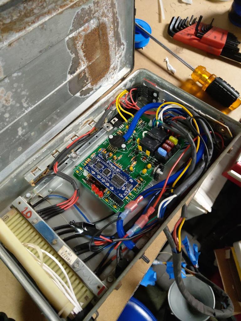
This was how it originally looked before the additional inline hacks to add more functionality.
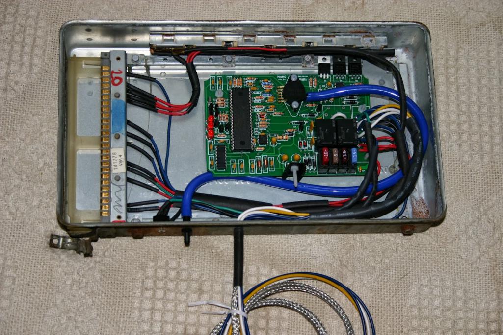
I wont show you the earlier versions I ran using the official Megasquirt 2.2 board as they were not at all pretty. I was in my 20s, poor, and still had a lot to learn. Think my first running MS conversion cost me somewhere around 100 bucks. Things have changed a lot since then.
Posted by: falcor75 Sep 13 2021, 11:14 PM
I went the ITB route for my 2.3 but my car isnt built for daily driving or milage. Its more of a autocross and country road dasher. I got the camsync for mine and its installed and hooked up but we didnt end up using it. The reason is that the car drives fine without it in Alpha-N and wasted spark. My yearly milage between april and october is around 1k or less.
What I'm most happy with my set up is the noise and the crisp response and the bluetooth monitoring that allows me to display engine data in a tablet on the dash.
What I'm not happy about is the low idle at startup for the first minute untill the engine heats up a bit. With my ITB's I would need to add an idle air control valve to really sort that out.
Posted by: Superhawk996 Sep 14 2021, 05:38 AM
Sadly, the more complicated it looks, the more I'm drawn to it. I'm weird that way.
Believe me, I understand the feeling...
@http://www.914world.com/bbs2/index.php?showuser=20845
Love the craziness -- the dream of getting a 914 to be 21st century maintenance free but what are you doing to do about the maintenance of oil leaks. 
@http://www.914world.com/bbs2/index.php?showuser=5834 Impressive - love the idea of getting the controls into the stock D-jet ECU box! Circuit minaturization of the the years is amazing.
Posted by: GregAmy Sep 14 2021, 06:00 AM
I spent a lot of time managing startup, controlling the AFR with WUE and idle RPM with ignition timing control (Idle RPMs Advance Timing)...and mine starts foot-off, with no aux air valve, and pretty much cores it.
It can be done w/o an idle control valve.
Posted by: ClayPerrine Sep 14 2021, 06:54 AM
If you don't have manifold vacuum at idle, but it runs fine at speed, you can run microsquirt in hybrid mode. It can use alpha-n at idle to accommodate the lack of vacuum, and speed density when driving to make it more efficient.
Look at the documentation, it is covered there.
Clay
Posted by: jd74914 Sep 14 2021, 07:10 AM
I spent a lot of time managing startup, controlling the AFR with WUE and idle RPM with ignition timing control (Idle RPMs Advance Timing)...and mine starts foot-off, with no aux air valve, and pretty much cores it.
It can be done w/o an idle control valve.

The key is controlling idle speed with timing as Greg said. A bit of ignition trough to settle the engine in works quite well, particularly if you increase the map resolution a bit in that range. Note that while optional with a TB/plenum you really need to do this with ITBs unless you want a lot of plumbing complication.
Since you have a really nice air box, I would highly recommend using a Bosch TMAP (temperature/map sensor) installed in a boss for the barometric correction. They aren't too expensive, hide well, and are very robust. If you want to go really crazy... some motorcycle MAP sensors, 1 per cylinder, with a IC used to pull the max manifold pressures would give a really good input to speed density. From what I've seen, the failing of most ITB speed density is that a physical signal average (4 tubes from each manifold running into a plenum) is a) highly damped and b)biased downward so it's not really a true MAP representation. Someone used to make a board to do that processing, though I haven't seen one in years.
Posted by: VaccaRabite Sep 14 2021, 08:13 AM
James is the man, and I'd take his thoughts as gospel.
What I would suggest though (and the way I wish I had done it) is to start with fuel and then do the spark. Don't do it all at once.
With my engine, I had the #$@ing fuel regulator plumbed backwards, which kept me from getting my first start. Since I had done fuel and spark at the same time, the troubleshooting as to WHY it would not start was extensive until I finally put a pressure gauge on the fuel rail.
Also, make sure you have a fuel pressure dial on or near your fuel rail. You are going to want this anyway when you are tuning to make sure your fuel pressure is correct.
My current MS setup is pretty different then what you are wanting (I'm using a throttle body and using MAP readings instead of a hybrid). My next one will have ITBs - but that's still to come.
Zach
Posted by: bbrock Sep 14 2021, 12:05 PM
@http://www.914world.com/bbs2/index.php?showuser=5834 I like it! How did mounting the boards inside the stock ecu case work? I have a couple spare D-Jet ECUs and would like to do the same.
I've had a couple crazy electronics projects. When we bought Nest thermostats for the house, I didn't like that they didn't interface with our high efficiency Mod/Con boiler with outdoor temperature reset (ODR). So I built a daughter board for a Raspberry Pi to continuously poll the Nest data and boost the boiler output temp when the system was recovering from an overnight temperature rollback. It does this by introducing resistance in stages to spoof the ODR circuit into thinking it is colder outside than it really is, and then boost output temps to catch up from the nightly rollbacks quicker.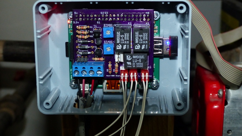
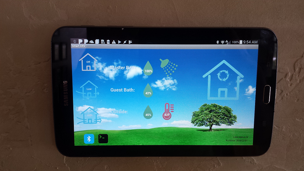
Then I didn't like the stupid way the controller for our heat recovery ventilation system worked so I used a logic sniffer to reverse engineer the logic signals and built an arduino-based controller to automate de-humidification and ventilation using sensor feedback. The control panel is now a wall-hung (not to be confused with well-hung) tablet and custom controller app. Before starting that project, I had never heard of a logic sniffer or Arduino; and had never attempted to write an android app!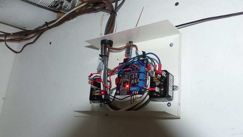
Let the craziness begin!
Posted by: JamesM Sep 14 2021, 01:08 PM
@http://www.914world.com/bbs2/index.php?showuser=5834 I like it! How did mounting the boards inside the stock ecu case work? I have a couple spare D-Jet ECUs and would like to do the same.
A very low tech solution, I just used gel epoxy to attach some nylon studs to the d-jet case.
Posted by: Montreal914 Sep 14 2021, 09:09 PM
@http://www.914world.com/bbs2/index.php?showuser=5834 I like it! How did mounting the boards inside the stock ecu case work? I have a couple spare D-Jet ECUs and would like to do the same.
I've had a couple crazy electronics projects. When we bought Nest thermostats for the house, I didn't like that they didn't interface with our high efficiency Mod/Con boiler with outdoor temperature reset (ODR). So I built a daughter board for a Raspberry Pi to continuously poll the Nest data and boost the boiler output temp when the system was recovering from an overnight temperature rollback. It does this by introducing resistance in stages to spoof the ODR circuit into thinking it is colder outside than it really is, and then boost output temps to catch up from the nightly rollbacks quicker.
Then I didn't like the stupid way the controller for our heat recovery ventilation system worked so I used a logic sniffer to reverse engineer the logic signals and built an arduino-based controller to automate de-humidification and ventilation using sensor feedback. The control panel is now a wall-hung (not to be confused with well-hung) tablet and custom controller app. Before starting that project, I had never heard of a logic sniffer or Arduino; and had never attempted to write an android app!
Let the craziness begin!
WOW! Really impressive!

...Then again, not surprising based on the rest of your restoration work!

Posted by: bbrock Sep 14 2021, 10:36 PM
WOW! Really impressive!
...Then again, not surprising based on the rest of your restoration work!
Thanks. But you really shouldn't encourage this kind of

But... yeah. I think I'm going ahead with sequential injection. The problem is that as far as I can learn, no Megasquirt board supports sequential injection without modification. The easy route would be Megasquirt 3 with the https://www.diyautotune.com/product/megasquirt-iii-ms3x-expansion-card/. It's also the most expensive option and is overkill because it provides eight additional injector channels for high impedance injectors.
The other option is to modify a Megasquirt 2 board according to the "sequential mod" instructions in the hardware manual. This removes some unused components to create two additional injector channels for a total of four. The new channels need to have a driver circuit and the solution I've decided on is http://jbperf.com/p&h_board/index.html from JBPerf.com This board drives 4 low impedance injectors which will let me use my stock injectors without having to run them through a resistor pack. The board has to be assembled and will cost ~$60 for the PCB and components. To keep the total cost down, I'm going to by the MS2 board as a kit - especially given that the sequential mod would require removing components from a pre-assembled board. The overall cost, not counting my time, will be in the ball park of an assembled microsquirt board so not adding much extra expense.
I guess the first order of business is to ship my injectors off to Mr. Injector to make sure they are serviceable. If they check out, I'll probably start ordering parts in late October or early November. Hopefully Mario will have online ordering turned back on by then as everything is on hold now.
Posted by: bbrock Sep 15 2021, 08:08 AM
@http://www.914world.com/bbs2/index.php?showuser=20845
Love the craziness -- the dream of getting a 914 to be 21st century maintenance free but what are you doing to do about the maintenance of oil leaks. @http://www.914world.com/bbs2/index.php?showuser=22428 I tried, but can't let this slide. Please shut your face about leaks! So far my girl doesn't seem to realize she is supposed to be dripping black pools onto the garage floor, and I'd rather not jinx it
Really though, back in the day, most of my low quality time with the car was spent in the engine bay either doing routine ignition maintenance which I hate, or chasing down fuel problems on a system that was well past its prime. Eliminate those and you are mostly down to oil changes and valve adjustments which I don't really mind. And of course, chasing down those rogue fluid pathways we won't mention.
![whistle[1].gif](style_emoticons/default/whistle[1].gif)
Posted by: Superhawk996 Sep 15 2021, 08:41 AM
I tried, but can't let this slide. . . .
 mission accomplished
Posted by: Mike D. Sep 15 2021, 10:31 PM
Ahhh, yes! The beginning of another 7 year thread!

Sorry, just piling on. Good Luck! and Have Fun!
Posted by: ClayPerrine Sep 16 2021, 06:21 AM
But... yeah. I think I'm going ahead with sequential injection. The problem is that as far as I can learn, no Megasquirt board supports sequential injection without modification.
Check out the https://www.diyautotune.com/product/ms3-pro-module/ It is a board to put in your own case, and it supports full sequential injection, plus a host of other add on items like traction control.
Clay
Posted by: Superhawk996 Sep 16 2021, 07:39 AM
Check out the https://www.diyautotune.com/product/ms3-pro-module/
Clay
 Spendy. Card alone is almost 25% of the complete DubShop Kit!
 Pretty cool though. I really don't like the form factor of MS boards other than the MicroSquirt. I also see they have a newer MicroSquirt with higher current driver circuits.
The DIY FI space is getting pretty interresting.

Posted by: bbrock Sep 16 2021, 08:24 AM
Check out the https://www.diyautotune.com/product/ms3-pro-module/
Clay
Spendy. Card alone is almost 25% of the complete DubShop Kit! Pretty cool though. I really don't like the form factor of MS boards other than the MicroSquirt. I also see they have a newer MicroSquirt with higher current driver circuits.
The DIY FI space is getting pretty interresting.
Yeah, it's a chunk of coin but competitive with a an assembled M3 with M3X and in a more compact form factor. It would still require a resistor pack or P&H driver card to run stock low impedance injectors. I'm still thinking the MS2 route seems most practical for me.
Speaking of injectors, I came across this post kind of lobbying against using old D-Jet Benz injectors. Wonder about people's thoughts relative to a 914.
https://www.benzworld.org/threads/megasquirt-what-is-it-and-why-do-i-want-it.1621243/#post-18055685
Posted by: jd74914 Sep 16 2021, 08:52 AM
They're certainly right in terms of the poor spray pattern/atomization. That said, the importance of all of that really is somewhat dependent on your intake design, mixing distance from valve, etc. Modern injectors are objectively better. The temperature thing is true too, high-impedance do run cooler generally, though I'm not sure that's why they are oversized. Personally, if you're comfortable adding a real fuel rail with anchors and not the hose-end style of OEM, I think new injectors are a worthy upgrade.
Posted by: jd74914 Sep 16 2021, 09:08 AM
But... yeah. I think I'm going ahead with sequential injection. The problem is that as far as I can learn, no Megasquirt board supports sequential injection without modification. The easy route would be Megasquirt 3 with the https://www.diyautotune.com/product/megasquirt-iii-ms3x-expansion-card/. It's also the most expensive option and is overkill because it provides eight additional injector channels for high impedance injectors.
The other option is to modify a Megasquirt 2 board according to the "sequential mod" instructions in the hardware manual. This removes some unused components to create two additional injector channels for a total of four. The new channels need to have a driver circuit and the solution I've decided on is http://jbperf.com/p&h_board/index.html from JBPerf.com This board drives 4 low impedance injectors which will let me use my stock injectors without having to run them through a resistor pack. The board has to be assembled and will cost ~$60 for the PCB and components. To keep the total cost down, I'm going to by the MS2 board as a kit - especially given that the sequential mod would require removing components from a pre-assembled board. The overall cost, not counting my time, will be in the ball park of an assembled microsquirt board so not adding much extra expense.
The JBPerf stuff works well (everything he makes that I've seen anyways). I don't think you can go wrong there.
If you go MS3 you get a n [unloaded] loop execution time of ~0.20 ms vs. ~0.33ms of a MS2. Think about that potential extra 0.13 ms of engine crispness.

I have an MS3X waiting to go in, but that's mostly because I got a really good deal on it [used] and am spoiled by having worked with a lot of higher end stuff (LR F88, etc.).
Posted by: Superhawk996 Sep 16 2021, 11:38 AM
Modern injectors are objectively better. . . . I think new injectors are a worthy upgrade.
Yeah - what he said. 50 years of learning and improvments in injectors since 1970. Why leave that on the table? Especially if you're going sequential. If just dumping fuel on the back of a closed intake valve with batch injection it doesn't matter as much. Sequential is a whole different ball game if pushing for the last bits in performance and emissions.
Posted by: bbrock Sep 16 2021, 05:00 PM
Modern injectors are objectively better. . . . I think new injectors are a worthy upgrade.
Yeah - what he said. 50 years of learning and improvments in injectors since 1970. Why leave that on the table? Especially if you're going sequential. If just dumping fuel on the back of a closed intake valve with batch injection it doesn't matter as much. Sequential is a whole different ball game if pushing for the last bits in performance and emissions.
You guys sure are good at spending my money
It makes sense though. Kind of a side point out of curiosity, Maybe I'm way off, but it seems like the injector location on the stock runners would be better for taking advantage of the better spray pattern of modern injectors than mounted higher in ITBs. It just seems like the ITBs would have more time for the fuel vapor to fall out of suspension or wind up stuck to the manifold walls. Maybe the velocity is enough that it is insignificant. I know nothing.Also, I'd like to hear more about the influence of fuel rails for realizing benefits from modern injectors. A plus to ease the sting of losing my cool custom air cleaner is reverting to a mostly stock (although less cluttered with vacuum lines) look in the engine bay. I'm wondering what I sacrifice by sticking with the hose-mounted rails.
Other than a further drain on the wallet, it looks like upgrading injectors would just require swapping the P&H driver board for http://www.jbperf.com/quad_ign_inj/index.html. Then there is the matter of selecting the right injectors which I know nothing about

Posted by: bbrock Oct 9 2021, 08:44 AM
An additional 800 miles of seat time in my car hasn't lessened my desire to ditch the carbs and dizzy. I continue researching how I want to approach this and have more questions.
- Do I need a crank sensor? To go full sequential I need a cam position sensor for sure. I've read that cam sensors are not as accurate as crank sensors but that is because of chain or timing belt slack. Type 4 cams are gear driven. Is there enough gear lash in distributor drive mechanism to affect position accuracy? I have no issue with adding a crank sensor, but it is the only part that will require dropping the engine so the question of whether it is necessary if I have a cam sensor has to be asked.
- I'd love to hear thoughts on whether modern injectors would be worth the cost if I don't upgrade the fuel rails. Still not sure what I want to do, but curious why modern fuel rails would make a difference.
- Anyone know when Mario plans to open online ordering on The Dub Shop site? It's been closed since June so he can catch up on orders and restock parts. Sure, I could reach out directly but seems counterproductive to pester a guy who is already swamped. I know some of you are in touch with him so wondered if you've heard anything.
That's it for now. There will be more.
Posted by: Superhawk996 Oct 9 2021, 09:07 AM
- Do I need a crank sensor? To go full sequential I need a cam position sensor for sure.
I’m gonna get flak but who cares.
No -- you don’t need a crank sensor in the technical sense.
Yes - agree you need a cam sensor for full sequential. If you know where the cam is, then you know when to fire the spark. You can infer where the crank is if you know where the cam is, but, the opposite is not true.
Case example. Early 90’s Miata NA 1.6L engines (timing belt driven cams) have a cam angle sensor only and they run great! Full sequential. However that crank angle sensor on a miata is actually sort of absolute position encoder. It is a $200+ sensor. That car uses to fire up literally in 1 crank shaft revolution or less because of that sensor. Most FI systems need a couple crank revolutions to work out the signal timing between the seperate crank and cam sensors to figure out where to put the spark.
Found a decent link on the Miata crank angle sensor signal if you care:
http://www.rivercityroad.com/garage/cas.htm
Eventually Mazda went to a more conventional Hall Effect crank sensor + Hall Effect cam sensor, probably due to cost and to become more consistent with OBD2 regulations.
The problem with cam only is if someone sells a sophisticated enough cam sensor off-the-shelf and who has the software to run cam only for a T4.
I’d talk with Mario if you get serious about it to understand what his cam sensor was, what he's doing with the signal, and what software he's running with it.
In the limited digging I've done, he seems to have what I'd consider the minimum for easy DIY success:
1) He's done it before with T4
2) He has a dyno
3) He offers a complete kit.
Not negating the great work done by the guys on this site either. Lots of good information here too but the further off the rails you get trying to do non-standard MegaSquirt, the more you're on your own
On your other question
- I'd love to hear thoughts on whether modern injectors would be worth the cost if I don't upgrade the fuel rails. Still not sure what I want to do, but curious why modern fuel rails would make a difference.
I don't think it will net you any performance. I haven't seen anyone saying the OEM fuel rails are a flow bottleneck. Personally, I'm just not a fan of how the weight of the fuel rails, and associated fuel hose are not well supported. Basically just cantilevered off the injectors. It works, but, it wouldn't fly by modern engineering standards and road load testing. That's my opinion.
@http://www.914world.com/bbs2/index.php?showuser=20845
Posted by: nditiz1 Oct 9 2021, 01:15 PM
I have only seen the crankfire setup that McMark was selling from Original Customs. With that said what is the adv to running the cam sensor?
If it was easier to install/cheaper big a significant amount/better signal/easier to setup I might entertain the idea. Are any of those advantages present? Also, I know Al Kosmal is currently working on a T4 - EFI setup.
Posted by: bbrock Oct 9 2021, 01:51 PM
I have only seen the crankfire setup that McMark was selling from Original Customs. With that said what is the adv to running the cam sensor?
If it was easier to install/cheaper big a significant amount/better signal/easier to setup I might entertain the idea. Are any of those advantages present? Also, I know Al Kosmal is currently working on a T4 - EFI setup.
The advantage is that I like to over complicate things
An objective is to get the best economy (especially in town) and lowest emissions I can. A cam sensor let's you go full sequential for spark and injection which in theory can give a little better driveability and economy at lower speeds, reduced emissions, and smoother idle. I know going sequential isn't going to gain me that much, but I like this kind of challenge.The descriptions for Marios' old NLA cam sync sensor says it must be used with a crank sensor. I'm not sure if the same will be true for the new one which will have a trigger wheel instead of flying magnet. If it were possible to get by with just a cam sensor and no crank sensor, you wouldn't have to drop the engine to do the conversion. I guess that might simplify the install regardless of spark and injection mode.
Posted by: Frank S Oct 9 2021, 03:56 PM
I have only seen the crankfire setup that McMark was selling from Original Customs. With that said what is the adv to running the cam sensor?
If it was easier to install/cheaper big a significant amount/better signal/easier to setup I might entertain the idea. Are any of those advantages present? Also, I know Al Kosmal is currently working on a T4 - EFI setup.
The advantage is that I like to over complicate things
An objective is to get the best economy (especially in town) and lowest emissions I can. A cam sensor let's you go full sequential for spark and injection which in theory can give a little better driveability and economy at lower speeds, reduced emissions, and smoother idle. I know going sequential isn't going to gain me that much, but I like this kind of challenge.The descriptions for Marios' old NLA cam sync sensor says it must be used with a crank sensor. I'm not sure if the same will be true for the new one which will have a trigger wheel instead of flying magnet. If it were possible to get by with just a cam sensor and no crank sensor, you wouldn't have to drop the engine to do the conversion. I guess that might simplify the install regardless of spark and injection mode.
Mario's cam sync is working togeher with the crank sync only. But you can run a missing tooth sensor in the dizzy for sequential ignition and fuel, so no need for the crank sensor. The dizzy sensors are also much easier to service if the sensor is failing...
Posted by: JamesM Oct 9 2021, 04:53 PM
- Do I need a crank sensor?
If you want to run any ignition control it is highly recommended. If you want to run full sequential i believe it is mandatory.
I highly recommend Mario's crank trigger setup for multiple reasons, however as you mentioned it does pretty much require you drop the engine in a 914 to install and/or service it. Well, maybe not required but you are going to want to.
More recently I have came across this crank sensor setup that looks like it would be easily serviceable with the motor in the car, but i havent personally run it so i cant speak at all to how well it works. Also its expensive and looks like it probably uses a VR sensor (one of the reasons i prefer Mario's setup is it uses a Hall sensor that gives a nice clear square wave output)
https://www.clewett.com/index.php?main_page=product_info&cPath=3_64&products_id=31
- I'd love to hear thoughts on whether modern injectors would be worth the cost if I don't upgrade the fuel rails. Still not sure what I want to do, but curious why modern fuel rails would make a difference.
I see no need to swap out the fuel rails.
These are my preferred injectors when running stock intake runners
https://www.fiveomotorsport.com/a280-a380-high-impedance-hose-type-fuel-injector/
Lots of advantages in my mind:
They are pretty much plug and play to the stock intake runners and fuel rails.
They have locking EV1 connectors
They are high impedance so no need to use inline resistors or run PWM control
They run at higher pressures for better atomization
They come documented with flow specs and voltage correction datasheet
They are brand NEW
Only potential downside is that you will most likely want to run them with a newer style fuel pressure regulator to run at higher pressures, but there are a few options there that easily install in place of the stock regulator.
I think the deciding factor though should really involve asking yourself the question, do i trust 50 year old injectors and if so, for how long?
A few years ago I was driving behind @http://www.914world.com/bbs2/index.php?showuser=27 out of Salt Lake on the way to RRC and wound up getting my car covered in oil when a sticky stock injector holed a piston in his brand new 2056. Given all the other modernizations you are putting in, i see no reason to stick with old injectors. Not to mention, the stock 2.0 injectors are absolutely HUGE for a 2.0L motor resulting in very small injector pulse widths at idle which produces less accurate fueling. In fact, back in the VERY early days (pre MS2) I had to run a special "hi-res" code variant to gain the resolution needed for proper idle control with the stock injectors. If you do want to run d-jet injectors the ones off a 1.7 are much more appropriately sized for the application.
Posted by: ClayPerrine Oct 9 2021, 04:56 PM
Add a 36-1 wheel behind the fan replacing the spacer, and use a Vanagon hall effect distributor for the cam sensor.
The vanagon distributor is a drop in for a Type-IV.
Clay
Posted by: bbrock Oct 9 2021, 06:17 PM
This is all great info everyone! Looks like I'll be adding a crank sensor which was the original plan anyway, but seeing that his new cam sensor will have a trigger wheel (I assume missing tooth) got me thinking.
Thanks @http://www.914world.com/bbs2/index.php?showuser=5834 for pointing me toward those injectors. I wasn't very clear before but I had already decided to go with new injectors. The question was whether to upgrade the fuel rails which I'd rather not do to keep the stockish appearance. I agree that going to all this trouble and running old injectors doesn't make much sense. I figured I'd need to replace the stock pressure regulator too.
You raise an interesting question about injector size though. I read somewhere that for running full sequential injection, it is better to err on the larger size for injectors. The rationale was that larger injectors allow for a shorter pulse width that allows for more of the squirt to go into an open intake valve and therefore could spread the benefit of sequential a little higher up the rpm range. Made sense to me but wonder what others think.
The vanagon distributor is an interesting idea. Didn't know that was an option.
Posted by: JamesM Oct 10 2021, 01:15 AM
You raise an interesting question about injector size though. I read somewhere that for running full sequential injection, it is better to err on the larger size for injectors. The rationale was that larger injectors allow for a shorter pulse width that allows for more of the squirt to go into an open intake valve and therefore could spread the benefit of sequential a little higher up the rpm range. Made sense to me but wonder what others think.
I think the theory is sound, shorter pulse width will buy you more time firing on an open valve. You could probably run some math to figure out what the exact rpm difference would be between a larger and smaller injector. Looking at the math before though was what made me loose interest in sequential in the first place, at least for my autox car. Only gains are in emissions/economy at idle/lower RPM and once past a certain injector duty cycle and depending on your cam duration you are firing on a closed valve either way. Given how my autox car is normally driven, wouldnt have had any advantages for me.
Also with these motors usually having to be tuned on the rich side everywhere, including idle anyways i don't know if it would wind up making any measurable difference at all.
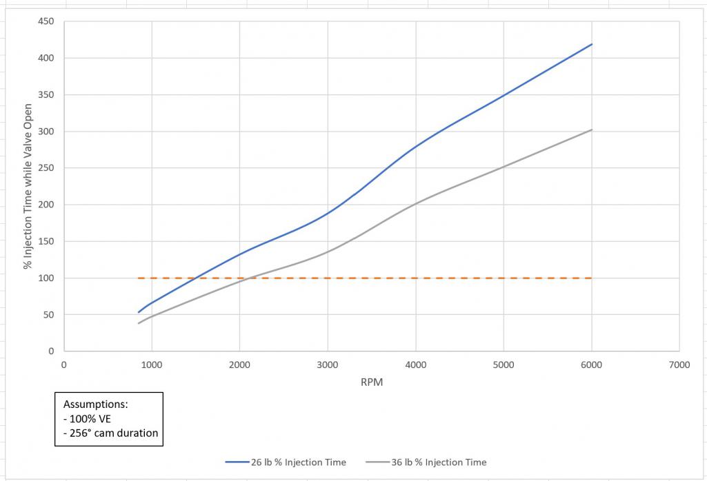
Posted by: bbrock Oct 10 2021, 12:20 PM
Okay, here's some fun with math. I calculated the theoretic time injectors on my engine need to be open to spray a dose as a percentage of the time the intake valve would be open. Not 100% sure my math is right but I got help on calculations here:
https://www.team-integra.net/threads/calculating-injector-pulse-width.46738/
and here:
https://www.physicsforums.com/threads/finding-out-the-time-duration-for-which-intake-valve-remains-open.584241/
The target AFR numbers are very tentative based on some earlier threads on the subject. I'm assuming I'll want the leanest mix at idle and cruising around 3000 rpm. Between idle and 3000 rpm would mostly be mild to moderate acceleration under load, and above 3K will mostly be WOT. I've barely dipped my toe into learning about managing mixtures, so those numbers might change as I learn more about AFR and how megasquirt can adjust timing and fuel dose in response to CHT. I think they are reasonable for this thought exercise though.
[Data Corrected]
Anyway, here are the results: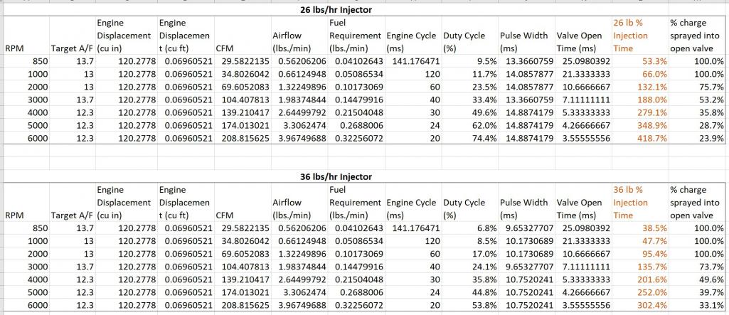
Posted by: Superhawk996 Oct 10 2021, 04:15 PM
I didn't check your math. I'm impressed though. No one bothers to do the math. Engineer at heart I guess!
I sure hope it's snowing out there . . . otherwise you're wasting valuable driving time doing injector math. Just sayin'.
Great discussion.
Posted by: bbrock Oct 10 2021, 04:18 PM
I didn't check your math. I'm impressed though. No one bothers to do the math. Engineer at heart.
I sure hope it's snowing out there . . . otherwise you're wasting valuable driving time doing injector math.
Predicting a foot of it tonight. Trying to get a project done before it gets cold enough to freeze in our greenhouse so no driving this weekend.
Posted by: bbrock Oct 10 2021, 07:03 PM
Found a major error in my calculations. I accidentally included a wrong column in the pulse width calculation. The corrected results are more interesting. It looks like with 26 lb injectors, it would start spraying part of the charge onto the backs of closed valves starting at about 1,500 rpm but with 36 lb injectors, that wouldn't begin until about 2,200 rpm. At 5k rpm about 29% of the charge from a 26 lb injector would spray into an open valve and that increases to about 40% with a 36 lb. injector.
Based on that, it seems like maybe larger injectors would be the way to go, but there must be a down side. Thoughts?
Posted by: JamesM Oct 11 2021, 02:21 AM
Found a major error in my calculations. I accidentally included a wrong column in the pulse width calculation. The corrected results are more interesting. It looks like with 26 lb injectors, it would start spraying part of the charge onto the backs of closed valves starting at about 1,500 rpm but with 36 lb injectors, that wouldn't begin until about 2,200 rpm. At 5k rpm about 29% of the charge from a 26 lb injector would spray into an open valve and that increases to about 40% with a 36 lb. injector.
Based on that, it seems like maybe larger injectors would be the way to go, but there must be a down side. Thoughts?
With larger injectors you lose some level of precision in fuel metering. I experienced this first hand when a early version of the MS1 code was unable to control the larger injector well enough for a decent idle.
At higher duty cycles both batch and sequential are putting the same amount of fuel though the open valve just as a result of how long the injector is firing for, so the only real difference is going to be seen below the point where the sequential starts firing on the closed valve.
So when comparing 26lb to 36lb injectors with sequential injection we are basically looking at a trade off between fueling precision across the entire operating range vs possible improvement in the 1500-2200 RPM range due to firing 100% on an open valve, and honestly how much time do you spend driving in that range? I think I would go with the smaller injector either way.
You really took me seriously on the math there! I cheated when i looked into it and just used recorded duty cycles across the RPM range for my setup from my datalogs, wound up with a similar result though, if I recall in my case the the cutoff was going to be somewhere around 1800rpm which for my purposes wasn't worth the effort/cost.
You give up the potential for some features going with Microsquirt but i think that platform has some advantages as well and in my mind it is the better compromise.
Posted by: bbrock Oct 11 2021, 11:59 AM
With larger injectors you lose some level of precision in fuel metering. I experienced this first hand when a early version of the MS1 code was unable to control the larger injector well enough for a decent idle.
I was reading about that last night. It sounded like this has been improved in later code versions. One discussion indicated it becomes a problem with pulse widths of 2 ms. Seems like it would be worth doing some more research.
So when comparing 26lb to 36lb injectors with sequential injection we are basically looking at a trade off between fueling precision across the entire operating range vs possible improvement in the 1500-2200 RPM range due to firing 100% on an open valve, and honestly how much time do you spend driving in that range? I think I would go with the smaller injector either way.
If my logic is right, batch firing delivers a charge in two squirts per cycle so a minimum of 50% of the charge will be sprayed onto a closed valve. That suggests some potential benefit up to 2000-3000 rpm depending on injector size because you'd have at least 25% more of the fuel charge spraying into open valves. Batch and sequential wouldn't be fully equivalent until at least 50% of the sequential charge goes on closed valves.
Engine speeds up to 3000 rpm covers pretty much all city driving, which has been about a third of the driving I've done in the car so far. Most of that is speeding up or slowing down and there isn't much chance to cruise a 3K rpm. That's exactly where I expect the most potential to improve fuel economy. Looking at my old mileage records for this car when driving on pure leaded gas, I consistently got mid to upper 30s on tanks of pure highway driving (remember it was 55 mph speed limit then) and don't expect much room for improvement there. But I got low to mid teens in town. Pretty horrible for such a small car really. I don't know if it is realistic, but low to mid 20s in town would be nice.
Ha ha. It was a fun little exercise. Glad to hear we came up with similar results. I wasn't sure how reliable this process for calculating would be.
Posted by: jd74914 Oct 11 2021, 12:38 PM
With larger injectors you lose some level of precision in fuel metering. I experienced this first hand when a early version of the MS1 code was unable to control the larger injector well enough for a decent idle.
I was reading about that last night. It sounded like this has been improved in later code versions. One discussion indicated it becomes a problem with pulse widths of 2 ms. Seems like it would be worth doing some more research.
I'm not sure this is really a 'code' issue. I would place it more in the loop execution time and hardware drivers. From what I've seen over the last decade or so, it doesn't appear the internal code is getting more efficient, the processers are just getting faster. So with that, best course of action for increased time resolution with MS looks to be going with newer hardware (ie: MS3).
At super low pulse widths you end up with this injector latency problem which can also pose some issues. On the 'cheap' injector side you aren't finding too many latency and flow matched sets. You could test that though...
Posted by: bbrock Oct 11 2021, 02:08 PM
I'm not sure this is really a 'code' issue. I would place it more in the loop execution time and hardware drivers. From what I've seen over the last decade or so, it doesn't appear the internal code is getting more efficient, the processers are just getting faster. So with that, best course of action for increased time resolution with MS looks to be going with newer hardware (ie: MS3).
At super low pulse widths you end up with this injector latency problem which can also pose some issues. On the 'cheap' injector side you aren't finding too many latency and flow matched sets. You could test that though...
Good info and that makes sense. I'm wondering if going sequential helps with this problem. Since each injector squirts only once per cycle rather than twice as in batch injection, the pulse widths are double for a give fuel demand. Would that not help with problems of low resolution for large injectors at low speeds? Looking at my tables, it looks like the 36 lbs/hr injector would still have a pulse width of 9.6 ms at idle which doesn't seem too small.
Posted by: jd74914 Oct 11 2021, 03:00 PM
Pulses of ~10 ms aren't too bad.
But...
I don't see where you add an engine pumping efficiency (VE) into the air flow calculation. I didn't check your calcs from a PV=nRT sense so I'm assuming those are correct in terms of air/fuel mass flows with perfect cylinder filling.
The engine is only going to be pumping maybe 10-30%* 'efficiently' at idle making your actual fuel flow requirements much less. Pulses of 0.96 ms are too short. Most injectors have 1-1.5 ms latency (voltage and fuel pressure dependent).
*Edit: Found a post showing Falcor76 has ~20% VE @ idle so I think these numbers are somewhat reasonable.
Posted by: Frank S Oct 11 2021, 03:49 PM
Fuel Injector Size:
https://thedubshop.com/pages.php?pageid=44
I'm running 21lb/hr and they are fine for a 120 HP Engine.
Don't go to large as this will be generate problems at idle and in overun conditions with to low pulswidth (out of the linear range of the injectors).
MS3 can deal much better with small puls width as the Dead Time Voltage Corretcion is not linear and MS3 is addressing that problem (which alone is a clear advantage if you compare with MS2 or Mircrosquirt).
Again Crank and/or Cam sensors:
A Crank sensor alone can only be good for Batch injection and Wasted Spark ignition.
Why? Because a engine cycle is 720° Crank rotation, so the ECU does not know if the engine is at #1 or #3 TDC. If you add a single tooth Cam Sensor in addition the ECU will be enabled to define #1 TDC, so you could run sequential fuel and spark.
If you run a Toothed Wheel Cam/Distibutor Sensor, this sensor allone will enable the ECU to define #1 TDC. This is because 720° Crank rotation = 360° Cam/Distributor rotation.
Sequential Modification:
You don't need to modify the MS2V3 board for sequential Fuel and Spark if you use the MS3. The MS3 daughtercard has all the outputs available, you just need to connect them to the JPB Board you are planning to use.
Posted by: bbrock Oct 11 2021, 04:04 PM
Pulses of ~10 ms aren't too bad.
But...
I don't see where you add an engine pumping efficiency (VE) into the air flow calculation. I didn't check your calcs from a PV=nRT sense so I'm assuming those are correct in terms of air/fuel mass flows with perfect cylinder filling.
The engine is only going to be pumping maybe 10-30%* 'efficiently' at idle making your actual fuel flow requirements much less. Pulses of 0.96 ms are too short. Most injectors have 1-1.5 ms latency (voltage and fuel pressure dependent).
*Edit: Found a post showing Falcor76 has ~20% VE @ idle so I think these numbers are somewhat reasonable.
Excellent! Yes, there's a little obscure note in the chart that says VE is calculated at 100%. This is all new to me so I was going to refine the values to include more realistic VE numbers later. Any guidance on some standard VE values to plug in? So far I've only found typical values at max HP.
This is obviously critical to the analysis. So assuming 10% VE, the idle pulse width should be around 1.3 ms with 26 lb injectors and, as you said, 0.96 ms with 36 lb. That puts the nail in the coffin for the larger injectors it seems. It seems even the 26 lb injectors might be pushing the limit. Assuming 20% VE at idle, I get a 2.7 ms pulse width with the 26s (1.9 ms with 36s).
Playing with VE a little and assuming a static 85% through the range above idle stretches out the theoretic band where sequential could potentially benefit. I've added curves for % of charge sprayed into open valves below with a reference line at 50% to show the point where sequential is no different from batch. Once I have more realistic guestimate numbers for VE, I'll post updated tables.
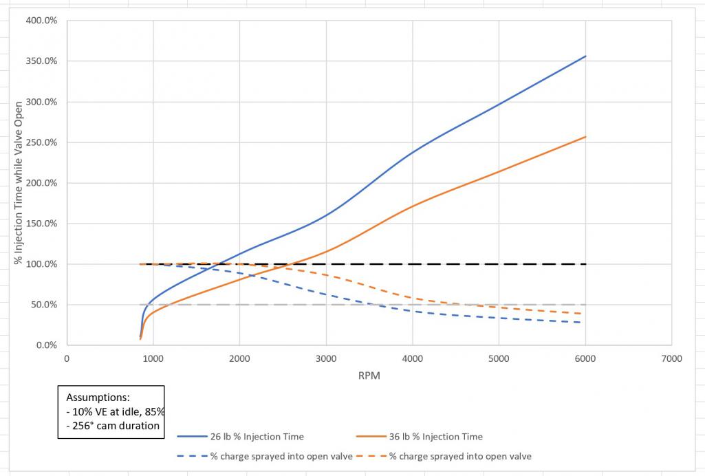
Posted by: crash914 Oct 11 2021, 04:06 PM
Call Mario.
Ask about the MAX EFI. will integrate O2 sensor, cam sync, CNP, full sequential.
It works well.
Posted by: bbrock Oct 11 2021, 07:24 PM
Well no reason to stop this insanity now, so here's more fun with math. I found a good discussion about VE vs engine speed for a stock 2.0L on Pelican. It didn't provide a nice table of VEs I would have liked, but led to enough info to make some WAGs to get closer with my chicken scratch estimates. I learned that VE typically follows the torque curve with peak VE being at about the same engine speed as peak torque. I also learned that typical peak VE values for 4 cylinder, 2 valve, overhead cam engines is 75-80% So I plotted a graph using 10% VE at idle to represent worst case in terms of small pulse width and max of 80% at about 3800 rpm which looks about where the 2.0L peaks (I was too lazy to look up the actual peak), and I dropped it to 60% @ 5800 rpm - again, just trying to match the shape of the torque curve. Then I had Excel calculate a polynomial equation for the shape and used that to plug in VE values in my tables. Whew - we're into some nerd shit now!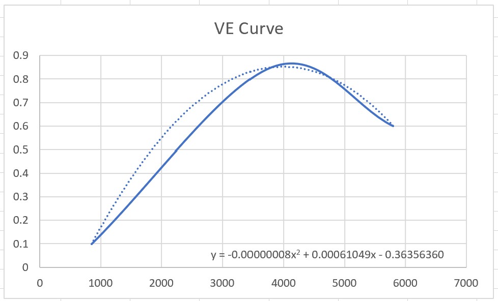
The results are interesting.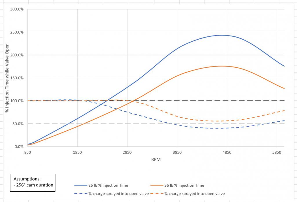
With this adjustment, both injectors extend the range where sequential would spray more of the charge into open valves than batch. Really intriguing is that the 36 lb injectors would still be spraying all or nearly all of the charge into open valves into the low 3ks which would be potential efficiency gains even into highway cruising speeds. In fact, the 36 lb never dips below 50% of charge going into open valves. But... there is still that pesky 0.94 ms pulse width @ idle. It would be nice to know what that minimum VE would actually be because even at 20% VE, the minimum pulse width climbs to 1.9 ms which might just be doable with MS3.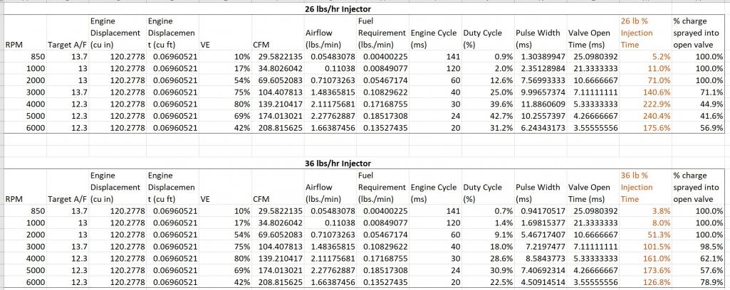
Posted by: bbrock Oct 11 2021, 07:45 PM
Fuel Injector Size:
https://thedubshop.com/pages.php?pageid=44
I'm running 21lb/hr and they are fine for a 120 HP Engine.
Don't go to large as this will be generate problems at idle and in overun conditions with to low pulswidth (out of the linear range of the injectors).
MS3 can deal much better with small puls width as the Dead Time Voltage Corretcion is not linear and MS3 is addressing that problem (which alone is a clear advantage if you compare with MS2 or Mircrosquirt).
I think I need to look a little more into MS3 or maybe the MAX EFI option @crash914 mentioned to see if they would let me run a smaller pulse width. MS3 would add about $200 to the project ($100 more than MS2 for the board kit plus $100 for the MS3X board to get the sequential output channels.
I've looked at Mario's and a couple other injector calculators and they all followed the same equation. Looks to me like they are just sizing the injector to be able to provide enough charge per cycle for the HP to be generated. Makes sense but it looks like squeezing efficiency our of sequential injection really depends on the timing of when the charge is sprayed to get as much as possible into the open valve for better atomization. Hence, the obsession over the larger injectors.
A Crank sensor alone can only be good for Batch injection and Wasted Spark ignition.
Why? Because a engine cycle is 720° Crank rotation, so the ECU does not know if the engine is at #1 or #3 TDC. If you add a single tooth Cam Sensor in addition the ECU will be enabled to define #1 TDC, so you could run sequential fuel and spark.
If you run a Toothed Wheel Cam/Distibutor Sensor, this sensor allone will enable the ECU to define #1 TDC. This is because 720° Crank rotation = 360° Cam/Distributor rotation.
Good info!
You don't need to modify the MS2V3 board for sequential Fuel and Spark if you use the MS3. The MS3 daughtercard has all the outputs available, you just need to connect them to the JPB Board you are planning to use.
I looked into the daughter board and you still have to add the MS3X board to get the sequential output channels. Seems kind of weird MS3 doesn't have at least 4 injector channels built in, but I haven't found anything to indicate otherwise. The MS2 mod is really just removing a few components and adding some jumpers to repurpose unused features as output pins for injectors. If you are building the board from kit, the mod is more just skipping a few steps on assembly. Still, if MS3 can handle short pulse widths, that would be a good reason to use it.
Posted by: Frank S Oct 11 2021, 10:55 PM
[quote]Sequential Modification:
You don't need to modify the MS2V3 board for sequential Fuel and Spark if you use the MS3. The MS3 daughtercard has all the outputs available, you just need to connect them to the JPB Board you are planning to use.
[/quote]
I looked into the daughter board and you still have to add the MS3X board to get the sequential output channels. Seems kind of weird MS3 doesn't have at least 4 injector channels built in, but I haven't found anything to indicate otherwise. The MS2 mod is really just removing a few components and adding some jumpers to repurpose unused features as output pins for injectors. If you are building the board from kit, the mod is more just skipping a few steps on assembly. Still, if MS3 can handle short pulse widths, that would be a good reason to use it.
[/quote]
I wasn't clear about the board. I thought about adding this:
http://jbperf.com/quad_ign_inj/index.html
Instead of the MS3X board.
Regarding your fuelinjector thoughts, you don't want to spray into the open valve.
MS3 is providing so much more value over MS2 that it is fully worth the extra $$ and I think if you would talk to the guys at DYI Autotune, they would also sell a MS2 kit without a MS2 daughtercard and adding a MS3 daughtercard therefore, which will remove some cost at least.
The MS3 dauthercard will also fit into the MS2 case if you slightly modify it and the MS2 case will also fit into the original D-Jet housing if you want to stay with the original look.
Posted by: JamesM Oct 12 2021, 01:17 AM
It sounds like you really want to go with the 36lb injectors
Larger injectors will always have less resolution smaller ones BUT 36lb injectors wont be an issue with an MS2 or newer CPU, it was only MS1 hardware that lacked the resolution under the stock code base to control them properly at idle. If I recall it wasn't so much an issue with the speed of the CPU as it was the limited CPU register capacity which is why they were able to address it with a custom code version that gave up other features in order to gain extra register space. We are talking ancient history here (15 or so years ago when all the MS code was written in assembly) so im not 100% on the specifics, but operationally hasn't been an issue since the early days, I ran the stock 2.0 (36lb) injectors for years, no big deal.
That being said, because you do loose some resolution with the larger injectors you will want to be sure all your injection related settings, especially the injector dead time and voltage correction factors are set as exact as possible (something that is impossible with stock injectors) as having the larger injectors amplifies mixture issues due to minor voltage fluctuations.
Given that fact along with what you seem to be going for here 'Frank S' brings up a good point about MS3 actually having a full table for injector voltage correction vs the MS2s linear correction. I had completely forgotten about that feature difference but am now reminded that the linear correction was one of the things that slightly annoyed me once I changed over to injectors that actually had documented voltage correction tables with them. Given you shouldn't see more than a 1-2 volt delta under normal operation conditions the linear settings get you pretty damn close (i can kick on my headlights with no AFR change noted) so for me it was splitting hairs, but if you really want to optimize it with the larger injectors, having the full correction table may be the way to go.
As for PW at idle, ill have to see if i have any old logs, but if i recall on a stock motor with the large injectors I was sitting somewhere in the low to mid 2ms range. Issue with the original MS1 code though was that it could only control PW in .1ms increments and the AFR difference between a 2.2ms and 2.3 ms injection pulse at idle with a 36lb injector was surprisingly large. Thankfully that is no longer an issue.
I know you haven't built your system yet, but based on what i have seen you doing so far I'm going to call it now and say you are going to wind up with the most precise (and thoroughly planned out) MS build to date.

Posted by: jd74914 Oct 12 2021, 07:08 AM
A Crank sensor alone can only be good for Batch injection and Wasted Spark ignition.
Why? Because a engine cycle is 720° Crank rotation, so the ECU does not know if the engine is at #1 or #3 TDC. If you add a single tooth Cam Sensor in addition the ECU will be enabled to define #1 TDC, so you could run sequential fuel and spark.
If you run a Toothed Wheel Cam/Distibutor Sensor, this sensor allone will enable the ECU to define #1 TDC. This is because 720° Crank rotation = 360° Cam/Distributor rotation.
Good info!
I actually have a toothed cam wheel with hall effect trigger somewhere in the garage. Never used it, but let me see if I can dig it out to show how it was done.
Posted by: jd74914 Oct 12 2021, 07:18 AM
I've looked at Mario's and a couple other injector calculators and they all followed the same equation. Looks to me like they are just sizing the injector to be able to provide enough charge per cycle for the HP to be generated. Makes sense but it looks like squeezing efficiency our of sequential injection really depends on the timing of when the charge is sprayed to get as much as possible into the open valve for better atomization. Hence, the obsession over the larger injectors.
What you're seeing is typical of automotive aftermarket...just general equations without much value besides really rough approximations.
I'm really enjoying seeing your calculations-thank you!
I think I need to look a little more into MS3 or maybe the MAX EFI option @crash914 mentioned to see if they would let me run a smaller pulse width. MS3 would add about $200 to the project ($100 more than MS2 for the board kit plus $100 for the MS3X board to get the sequential output channels.
Personally, I'd push to an MS3...but its easy to spend other people's money. With an MS2 loop speed of 0.33 ms, assuming engine speed of 3000 rpm, you're looking at the engine moving 5.94 degrees per loop execution time...MS3 @ 0.2 ms gives you 3.6 degrees. Pretty decent difference. Caveat here-I'm not really sure how the code is structured. You would hope they would prioritize some things like injector/ignition switching as well as engine position calculation, but I'm not sure.
As a side note, The extreme high end stuff has hardware angle clocks (typ. FPGAs) to keep these kind of calculations off of the main processor. The use the main processor to schedule events to happen at definitely crank angles vs. times. Subtle difference that doesn't really matter for a 50 year old engine, but maybe interesting.
Given that fact along with what you seem to be going for here 'Frank S' brings up a good point about MS3 actually having a full table for injector voltage correction vs the MS2s linear correction. I had completely forgotten about that feature difference but am now reminded that the linear correction was one of the things that slightly annoyed me once I changed over to injectors that actually had documented voltage correction tables with them. Given you shouldn't see more than a 1-2 volt delta under normal operation conditions the linear settings get you pretty damn close (i can kick on my headlights with no AFR change noted) so for me it was splitting hairs, but if you really want to optimize it with the larger injectors, having the full correction table may be the way to go.
I think this correction table is very important. Not a direct comparison, but when tuning high-strung bike motors we found having full voltage correction was exceedingly important. Those were engines with poor charging capability and weight optimized harnesses so voltage drop was a thing. As James said, likely not a huge issue for you but when really pushing it...
Now, you've been looking at all of this in terms of fueling during valve opening. This isn't necessarily ideal when you start looking at air/spray flow velocities and mix transit times into the cylinder. The delay is real, particularly due to the variation in intake velocity with crank angle as the valves open. For real optimization you need to tune the injector end angle at all engine speeds and load points...
https://www.motec.com.au/forum/viewtopic.php?t=769
I've been fortunate enough to have a load bearing dyno to do sweeps, but this should be doable on the road. Just needs some more logging and drive time. Optimized injection timing minimizes wall condensation and actually can yield some pretty meaningful efficiency gains. You do need good engine position resolution to do this well which really pushes towards the crank sensor (say 36:1 or 60:1 wheel).
Posted by: Superhawk996 Oct 12 2021, 08:13 AM
You're becoming a real Geek. 
I've had these sitting on my shelf since college. I think you need them more than I do. PM me your address and they are on their way to you. 
Posted by: bbrock Oct 12 2021, 08:38 AM
You guys are awesome!
I was reading through the MS3 tuning manual last night and it does look like MS3 will be worth the added coin. I've officially gone from Microsquirt all the way up to MS3. I'm still a bit confused about cards though and am probably missing something. It looks like the daughter boards are intended to upgrade older boards to newer so an MS2 daughter card is used to upgrade an MS1 to MS2 and MS3 daughter upgrades MS2. Either of these provides only 2 injector channel outputs and the jbperf boards require 4 inputs to drive 4 injectors independently. So it seems you need to modify/expand either MS board to get 4 output channels. Difference being that MS3X can drive high impedence injectors directly where modded MS2 requires a jbperf board. I might be missing something though.
@http://www.914world.com/bbs2/index.php?showuser=1659 you and @http://www.914world.com/bbs2/index.php?showuser=18632 anticipated my next question. I knew talking about spraying into open valves was likely incorrect but was using it as shorthand for getting the most complete atomized charge into the combustion chamber. I think/hope the logic for my calculations still applies even though they ignore the timing issue. Last night I read about crank angle settings in the MS3 manual. They said you usually want the injectors to stop spraying just as the valve begins to open and suggested 360 degrees as a starting point. They then say further tuning was needed with dyno or road testing and my obvious question was, how? The link to the motec article answers that perfectly!
Now after reading the MS3 manual about individual cylinder tuning, I'm looking at my Bursch collector piping and thinking, hey, I could mount 4 lambda sensors in there ...
Posted by: VaccaRabite Oct 12 2021, 10:22 AM
I worry that the larger picture of building an EFI for a 4 banger aircooled motor is getting lost in the weeds here.
These aren't exactly smooth running motors to begin with, and the engine bay is somewhat open to the elements. I'd reconsider using the Microquirt and adding some simplicity back into your equation. The operational differences between wasted spark and individually controlled plugs isn't going to be noticeable when you are driving the car, but will make it more challenging to build and tune - increasing the time before you are back to driving the car again.
Zach
Posted by: bbrock Oct 12 2021, 11:10 AM
I worry that the larger picture of building an EFI for a 4 banger aircooled motor is getting lost in the weeds here.
Was it that obvious?
You've probably given the best advice of all here, but I'm already down the rabbit hole. Here's the view from my window today so I'm already done driving until the middle of June '22. I need something to occupy myself on these long winter nights

Posted by: JamesM Oct 12 2021, 12:04 PM
I worry that the larger picture of building an EFI for a 4 banger aircooled motor is getting lost in the weeds here.
These aren't exactly smooth running motors to begin with, and the engine bay is somewhat open to the elements. I'd reconsider using the Microquirt and adding some simplicity back into your equation. The operational differences between wasted spark and individually controlled plugs isn't going to be noticeable when you are driving the car, but will make it more challenging to build and tune - increasing the time before you are back to driving the car again.
Zach
I already tried to sell him on the easy button (well slightly easier button anyways).
As someone who enjoys this stuff though I full support the effort to go completely overkill!
I'm actually sort of curious about what will be needed to properly dial in the injector timing and what sort(if any) difference it will wind up making. The tuning process with batch injection is fairly straight forward for the home mechanic with a wideband sensor but to fully dial in sequential injector timing... I suspect that's going to take some serious time and heavy equipment.
Lots of stacked variables to deal with.
Posted by: JamesM Oct 12 2021, 12:33 PM
Im just going to leave this here to give you more to consider about your injector selection.
This is the datasheet I got with those A280H injectors
The 26lb rating was at 3bar pressure however they provide the flow specs and voltage corrections for running them all the way up to 7 bar!!!
I would imagine the 36lb sets come with similar abilities.
Have read that higher pressures improve atomization, and if you wanted to look at shortening your injector pulse even further, its something to consider.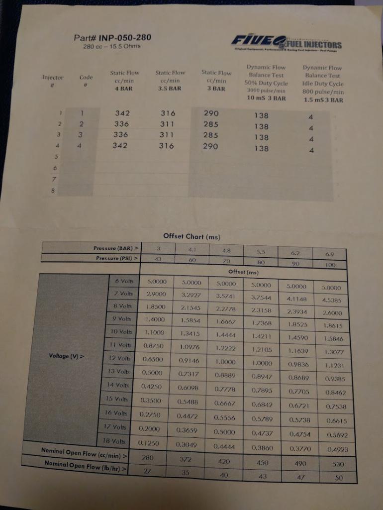
Posted by: bbrock Oct 12 2021, 12:35 PM
I worry that the larger picture of building an EFI for a 4 banger aircooled motor is getting lost in the weeds here.
These aren't exactly smooth running motors to begin with, and the engine bay is somewhat open to the elements. I'd reconsider using the Microquirt and adding some simplicity back into your equation. The operational differences between wasted spark and individually controlled plugs isn't going to be noticeable when you are driving the car, but will make it more challenging to build and tune - increasing the time before you are back to driving the car again.
Zach
I already tried to sell him on the easy button (well slightly easier button anyways).
As someone who enjoys this stuff though I full support the effort to go completely overkill!
Enabler!
Lots of stacked variables to deal with.
You and me both. This is for sure going to be the biggest challenge. I may eat my words, but tuning for sequential spark doesn't look much different from wasted spark other than throwing some extra $ at hardware and a few configuration settings to tell the ECU the timing rules get applied across 4 channels instead of two. I'm sure there will be some head scratching in there but doesn't seem quite as daunting as sequential injection. Worst case if I get in too far over my head is that batch injection will still be an option.
Posted by: bbrock Oct 12 2021, 12:36 PM
Im just going to leave this here to give you more to consider about your injector selection.
This is the datasheet I got with those A280H injectors
The 26lb rating was at 3bar pressure however they provide the flow specs and voltage corrections for running them all the way up to 7 bar!!!
I would imagine the 36lb sets come with similar abilities.
Have read that higher pressures improve atomization, and if you wanted to look at shortening your injector pulse even further, its something to consider.
I was actually wondering about that. What's a safe pressure a Bosch 69133 could run? Need to find specs.
Posted by: KELTY360 Oct 12 2021, 01:36 PM
Obviously, while the snow is on the ground you need to build a dyno in your garage.
You'll never be able to test your results til you do and you'll never be satisfied til you can test the results of all variables.
Posted by: Superhawk996 Oct 12 2021, 01:54 PM
Here's the view from my window today so I'm already done driving until the middle of June '22.
 Don't be such a cynic. With all the climate change it'll be 60F by late next week and then you'll be back to mud season!
Posted by: bbrock Oct 12 2021, 01:57 PM
Obviously, while the snow is on the ground you need to build a dyno in your garage.
You'll never be able to test your results til you do and you'll never be satisfied til you can test the results of all variables.
Ha! You talk like you have met me... oh wait... you HAVE
The testing will be a bit of a bummer. If I was a good person, I'd tune this thing with wasted spark and batch injection, drive it long enough to collect some data, and THEN switch to sequential. That seems too much like work though.
BTW, I assume MS can calculate and log fuel consumption as mpg - correct?
Posted by: KELTY360 Oct 12 2021, 02:00 PM
Obviously, while the snow is on the ground you need to build a dyno in your garage.
You'll never be able to test your results til you do and you'll never be satisfied til you can test the results of all variables.
Ha! You talk like you have met me... oh wait... you HAVE
The testing will be a bit of a bummer. If I was a good person, I'd tune this thing with wasted spark and batch injection, drive it long enough to collect some data, and THEN switch to sequential. That seems too much like work though.
BTW, I assume MS can calculate and log fuel consumption as mpg - correct?
You're asking me?
 I still think a log is something you burn in the fireplace.
Posted by: bbrock Oct 12 2021, 02:31 PM
Don't be such a cynic. With all the climate change it'll be 60F by late next week and then you'll be back to mud season!It's actually supposed to be 60 this weekend. Whose the cynic now?
You're asking me?
I still think a log is something you burn in the fireplace.That question was for the collective. I expected nothing more from you
BTW...
https://www.youtube.com/watch?v=XUX_YWsECWs
Posted by: Superhawk996 Oct 12 2021, 02:37 PM
BTW...
see PM
Posted by: ClayPerrine Oct 13 2021, 06:28 AM
If you want distributorless ignition, there is an easier way.
GM built DIS (waste spark) ignition systems on a LOT of their cars in the 80s/90s. Some of the 4 cylinder models used an external sender for the trigger. Years ago, I fitted waste spark to the Type -IV engine in my 914 using the GM system. I took the flywheel off the motor, and machined in the correct grooves to trigger the sender, and mounted the sender in the hole in the back of the case used for flex plate bolts in VWs. I made the mount eccentric so I could fine tune the timing.
This has to be machined into the engine side of the flywheel, properly indexed to the hole.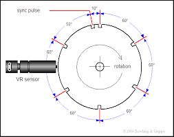
The ignition module has a base timing curve that it will follow if there is no ECU input. The curve is really close to the stock 914 advance curve. I had carbs on the engine at the time, and it ran way better with the distributorless ignition than it did with the stock distributor.
There is lots of documentation out there for connecting megasquirt to GM waste spark ignition.
The only reason I pulled it off the car was that I had a starter eat the ring gear on the flywheel. I was in a hurry, and had to get the car running to get to work. So I put the stock distributor back in. I still have all the parts in my attic.
Posted by: jd74914 Oct 13 2021, 07:24 AM
That question was for the collective. I expected nothing more from you
BTW...
Well...since you asked...
You can get a wireless strain gauge amplifier; strain gauge up your axles, and have live torque measurement...all of the time!
http://www.izzeracing.com/ewExternalFiles/Izze_W_SGAMP_V2_Datasheet.pdf
Same thing could be done with homemade hardware or from other vendors...
Posted by: Frank S Oct 14 2021, 09:58 AM
Had a chance to check some of my data.
With the 21lb/hr injectors I run with 5ms PW at idle and down to 2.5ms in some areas in overrun, which is the smalest PW I have.
Linear range of my injectors ends at 1.5ms and if you add deadtime this is getting close to the none linear region.
This is meassured data, not calculated...
Posted by: Frank S Oct 14 2021, 10:03 AM
And here how it looks like if you integrate the MS3 into the D-Jet housing: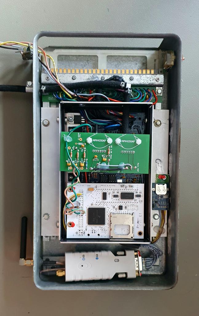
Just the Injector driver board for Full Sequential is not in jet...
Posted by: bbrock Oct 14 2021, 05:36 PM
And here how it looks like if you integrate the MS3 into the D-Jet housing:
Just the Injector driver board for Full Sequential is not in jet...
I like it! Is that a bluetooth module at the bottom? And are you running inputs/outputs to the original ECU harness header?
Thanks for posting those pulse widths. That is VERY helpful.
Posted by: bbrock Oct 14 2021, 05:49 PM
Had a chance to check some of my data.
With the 21lb/hr injectors I run with 5ms PW at idle and down to 2.5ms in some areas in overrun, which is the smalest PW I have.
Linear range of my injectors ends at 1.5ms and if you add deadtime this is getting close to the none linear region.
This is meassured data, not calculated...
I plugged 21 lbs/hr into my spreadsheet and played with the VE at idle until I got glose to 5ms PW. It hit at about 29%. I used 25% as a lower VE for a margin of safety and recalculated the VE curve. With that adjustment, calculated PW for 36 lb injectors at 850 rpm is 2.5ms (3.5ms for 26 lb.).
Posted by: Frank S Oct 15 2021, 01:57 AM
And here how it looks like if you integrate the MS3 into the D-Jet housing:
Just the Injector driver board for Full Sequential is not in jet...
I like it! Is that a bluetooth module at the bottom? And are you running inputs/outputs to the original ECU harness header?
Thanks for posting those pulse widths. That is VERY helpful.
Yes, this is a bluetooth module at the bottom and the real time clock module at the right and yes I'm running inputs and outputs through the original ECU harness header but for the actual install I had to feed also some extra cables as I have added a second EGO sensor and an external knock module.
Posted by: JamesM Oct 15 2021, 10:15 AM
Had a chance to check some of my data.
With the 21lb/hr injectors I run with 5ms PW at idle and down to 2.5ms in some areas in overrun, which is the smalest PW I have.
Linear range of my injectors ends at 1.5ms and if you add deadtime this is getting close to the none linear region.
This is meassured data, not calculated...
I plugged 21 lbs/hr into my spreadsheet and played with the VE at idle until I got glose to 5ms PW. It hit at about 29%. I used 25% as a lower VE for a margin of safety and recalculated the VE curve. With that adjustment, calculated PW for 36 lb injectors at 850 rpm is 2.5ms (3.5ms for 26 lb.).
Well your math is good as that is roughly what i was seeing when running the stock 36lb injectors.
Now stop playing with spreadsheets and build the damn thing
Posted by: bbrock Oct 15 2021, 06:21 PM
Had a chance to check some of my data.
With the 21lb/hr injectors I run with 5ms PW at idle and down to 2.5ms in some areas in overrun, which is the smalest PW I have.
Linear range of my injectors ends at 1.5ms and if you add deadtime this is getting close to the none linear region.
This is meassured data, not calculated...
I plugged 21 lbs/hr into my spreadsheet and played with the VE at idle until I got glose to 5ms PW. It hit at about 29%. I used 25% as a lower VE for a margin of safety and recalculated the VE curve. With that adjustment, calculated PW for 36 lb injectors at 850 rpm is 2.5ms (3.5ms for 26 lb.).
Well your math is good as that is roughly what i was seeing when running the stock 36lb injectors.
Oh wow! There are several school teachers who would likely keel over in shock to here that if they are still alive.
It's a great relief to have real measurements that agree with my chicken scratch! Thank you.
Now stop playing with spreadsheets and build the damn thing
Shit. I thought this was just a mental exercise. You mean I actually have to build this?
Got a few smaller projects I need to finish before I can dedicate serious time, but I'm ready to pull the trigger on ordering the MS3 kit. Think I finally figured out how the daughter boards figure in. If I've got it right, the v3 board is just a base "non denominational" board and the daughter board determines which version of MS. That was a little muddy until I looked at the assembly instructions. Think I'm going to go with MS3Extra as it will be easier for only about an extra $50 overall.
I sent Mario an email to get an idea of when his goodies will be available for purchase again, and also when the v2 of his CAM SYNC might be ready. That would also greatly simplify things. He has this note on the description: "It will incorporate a small trigger wheel in stead of the flying magnet. For basic applications this can be used without a crank trigger. In performance applications both are still recommended."
Still not sure how much precision is being sacrificed using a gear driven distributor to send tach signal vs. a crank sensor.
Posted by: Frank S Oct 15 2021, 11:58 PM
Still not sure how much precision is being sacrificed using a gear driven distributor to send tach signal vs. a crank sensor.
In theorie you will sacrifice some precision, in paractice I don't experience a difference.
Posted by: bbrock Oct 16 2021, 10:42 PM
I've been wondering if there is an advantage in adding a CHT ring sensor on #3 spark plug to the system beyond just generally being able to track head temps. Since we have to run these engines a bit rich to keep the head temps down, it seems like the most efficiency at cruising could be had with a feedback loop between AFR and CHT so the mixture could go as close to stoich as possible while maintaining safe head temps. The TunerStudio manual talks about CLT to monitor coolant temp for warm up (I'll be mounting mine in the stock CHT location), but I'm not seeing anything about integrating CHT with the AFR targets or VE table. Would this be a bad idea?
Posted by: JamesM Oct 16 2021, 10:56 PM
Still not sure how much precision is being sacrificed using a gear driven distributor to send tach signal vs. a crank sensor.
This is entirely observational but "some"
I went from picking up my tach signal from a pertronix on a locked dizzy to Marios 36 tooth crank wheel and the difference under a timing light was visibly noticeable. couldn't tell you in a number what the difference was and im sure its very minor, like less than 1 deg, but with the dizzy trigger there was a bit of jitter under the timing light, the timing mark had a slight haze to it. After moving to the 36 tooth crank wheel the mark under a timing light was rock solid, like i was looking at a laser pointer.
Posted by: JamesM Oct 16 2021, 11:04 PM
I've been wondering if there is an advantage in adding a CHT ring sensor on #3 spark plug to the system beyond just generally being able to track head temps. Since we have to run these engines a bit rich to keep the head temps down, it seems like the most efficiency at cruising could be had with a feedback loop between AFR and CHT so the mixture could go as close to stoich as possible while maintaining safe head temps. The TunerStudio manual talks about CLT to monitor coolant temp for warm up (I'll be mounting mine in the stock CHT location), but I'm not seeing anything about integrating CHT with the AFR targets or VE table. Would this be a bad idea?
I mean it would be cool if you could figure out a way to do it, but AFAIK its not an existing feature.
The other issue you need to look at is the spark plug ring sensors are are thermocouples where as Megasquirt uses thermistors for temp sensors.
Posted by: GregAmy Oct 17 2021, 07:05 AM
$12 to add voltage input for CHT to my Microsquirt for monitoring and logging head temps.
https://www.adafruit.com/product/1778
This thread has gone off the rails, from driving a 50-yr-old car (with a 75-yr-old engine design) in The Real World to thinking this can be micro-controlled to a modern level of efficiency. 
Just build something already!
And if you do follow through on this science project, it would be very cool if you did it in such a way that it could be re-tuned to basic wasted spark and batch injection, and you spent the dyno time to prove this was worth all those extra brain cycles and all that extra financial outlay. I know which spot on the table my twenty-spot would be palced on.
Have fun!
GA
Posted by: jd74914 Oct 17 2021, 07:44 AM
That’s not an uncommon feature in higher end ECUs. I wonder if you could bake it into a corrections table. The thing I’m not sure about it usually those cascade control loops have a large time constant between them (ie coolant temp correction runs 100x slower than O2 feedback). Of course, if the change is really small that likely doesn’t matter much.
Reading the TC in would be easy with an amplifier. You can get cheap ones on Sparkfun.
Posted by: Frank S Oct 17 2021, 07:57 AM
Still not sure how much precision is being sacrificed using a gear driven distributor to send tach signal vs. a crank sensor.
This is entirely observational but "some"
I went from picking up my tach signal from a pertronix on a locked dizzy to Marios 36 tooth crank wheel and the difference under a timing light was visibly noticeable. couldn't tell you in a number what the difference was and im sure its very minor, like less than 1 deg, but with the dizzy trigger there was a bit of jitter under the timing light, the timing mark had a slight haze to it. After moving to the 36 tooth crank wheel the mark under a timing light was rock solid, like i was looking at a laser pointer.
I think thats the jitter I'm seeing as well. But does that really mater?
So many here report back here that Microsquirt is working well for them and Microsquirt as well as MS2 have random injection timing (different from engine start to engine start and not paired to a specific event) if you run them batch injected. This is the main reason why I changed from MS2 to MS3 as the code for Injection timing is totaly different and also supports Timed Batch injection as the D-Jet does.
With this in place, the engine is behaving the same from egine start to engine start (clearly noticable if you compare the datalogs).
Also for ignition timing you are typically some degrees away from where spark knock really happens. So the 1° Jitter should be also fine therefore.
Posted by: Frank S Oct 17 2021, 08:05 AM
$12 to add voltage input for CHT to my Microsquirt for monitoring and logging head temps.
https://www.adafruit.com/product/1778
This thread has gone off the rails, from driving a 50-yr-old car (with a 75-yr-old engine design) in The Real World to thinking this can be micro-controlled to a modern level of efficiency.
Just build something already!
And if you do follow through on this science project, it would be very cool if you did it in such a way that it could be re-tuned to basic wasted spark and batch injection, and you spent the dyno time to prove this was worth all those extra brain cycles and all that extra financial outlay. I know which spot on the table my twenty-spot would be palced on.
Have fun!
GA
Sequential injection does not generate more HP than batch injection. But you can lean it out much better in partload which is leading to better fuel economy. Thats all.
Posted by: bbrock Oct 17 2021, 09:12 AM
Still not sure how much precision is being sacrificed using a gear driven distributor to send tach signal vs. a crank sensor.
This is entirely observational but "some"
I went from picking up my tach signal from a pertronix on a locked dizzy to Marios 36 tooth crank wheel and the difference under a timing light was visibly noticeable. couldn't tell you in a number what the difference was and im sure its very minor, like less than 1 deg, but with the dizzy trigger there was a bit of jitter under the timing light, the timing mark had a slight haze to it. After moving to the 36 tooth crank wheel the mark under a timing light was rock solid, like i was looking at a laser pointer.
I think thats the jitter I'm seeing as well. But does that really mater?
So many here report back here that Microsquirt is working well for them and Microsquirt as well as MS2 have random injection timing (different from engine start to engine start and not paired to a specific event) if you run them batch injected. This is the main reason why I changed from MS2 to MS3 as the code for Injection timing is totaly different and also supports Timed Batch injection as the D-Jet does.
With this in place, the engine is behaving the same from egine start to engine start (clearly noticable if you compare the datalogs).
Also for ignition timing you are typically some degrees away from where spark knock really happens. So the 1° Jitter should be also fine therefore.
One degree seems in line with my very unscientific method of wiggling the dizzy rotor to see how much play it has.
Posted by: Montreal914 Oct 17 2021, 09:44 AM
For the CHT sensor, I will be using a BMW motorcycle sensor 12627673407. It has the same thread as the stock D-Jet CHT. You can see it here with the #3 ring sensor that will be used as a readout. I might also use Greg Amy's gizmo to datalog.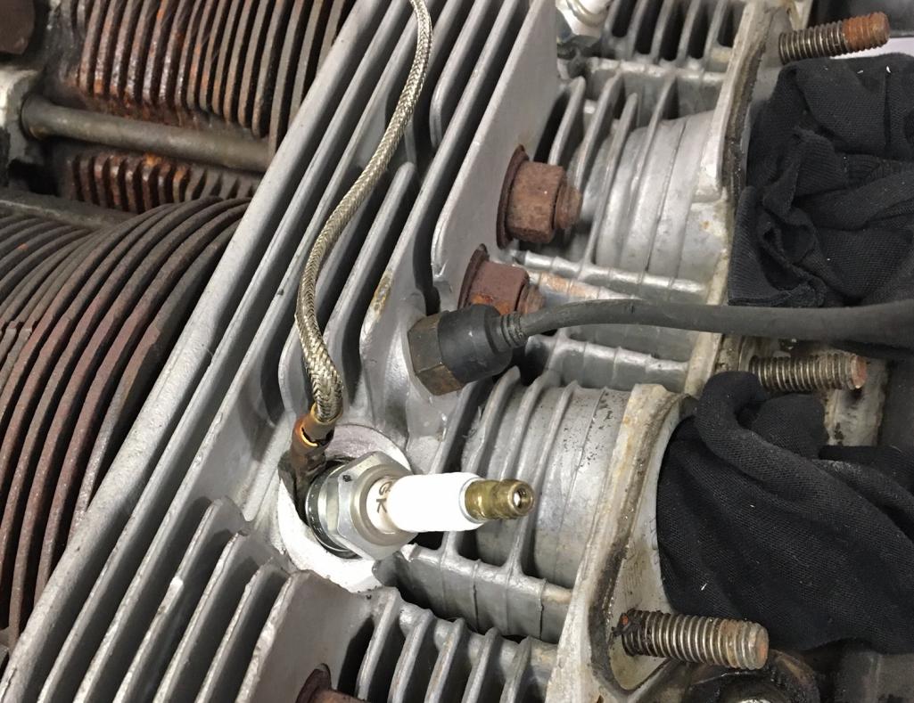
The CHT installation tool I did using a modified FLAP long reach socket. 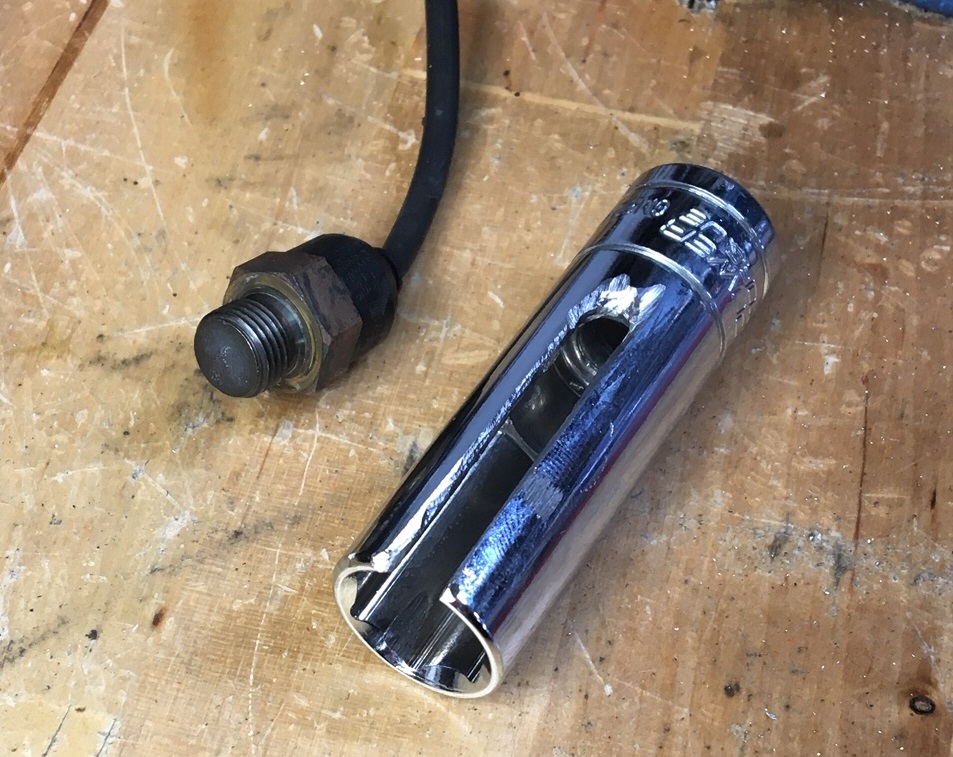
Last pictures is my fancy calibration process.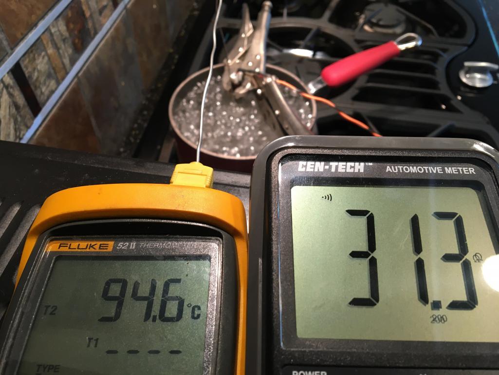
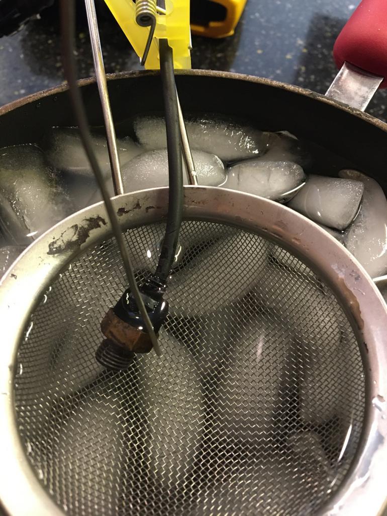
My microsquirt conversion will resume  once I send out my shell to the paint shop... Hopefully in the next few months
Posted by: bbrock Oct 17 2021, 09:51 AM
This thread has gone off the rails, from driving a 50-yr-old car (with a 75-yr-old engine design) in The Real World to thinking this can be micro-controlled to a modern level of efficiency.
Oh good. I'm in my comfort zone then
Thanks for the link to the amplifier. I remembered you had done that and was going to look up the thread where you described it to bookmark

I'll reveal my ignorance, but can a dyno tell us about differences in fuel economy? As Frank said, that's the only place I expect to see any difference. It seems advances in fuel and spark management are major factors in efficiency improvement of modern engines. Granted it is old school intake and combustion, and cooling technology so there will be limits.
As for performance - I've always found the stock 2.0L almost perfectly suited for my needs.
So continuing the theme of off the rails slippery slope, looks like I'll need some sort of gps integration for vehicle speed to be able to log mpg.
I'm going to order the MS3 kit soon but this project realistically won't begin in earnest until at least mid-December. It doesn't matter anyway since I want to buy a fair amount of kit from Mario and can't do that until he opens for shopping again.
Posted by: bbrock Oct 17 2021, 09:59 AM
For the CHT sensor, I will be using a BMW motorcycle sensor 12627673407. It has the same thread as the stock D-Jet CHT. You can see it here with the #3 ring sensor that will be used as a readout. I might also use Greg Amy's gizmo to datalog.
That looks like a great solution! I was going to use the modded GM sensor from the Dub Shop that bolts to the stock CHT location with an M10 bolt. I already have the bolt in there just to prevent any gunk from getting in the hole. Will still need to source a ring sensor #3 plug.
Posted by: Montreal914 Oct 17 2021, 10:08 AM
Will still need to source a ring sensor #3 plug.
This is an option: K-type TC Rings, readers w/outputs, etc...
http://thesensorconnection.com/
Posted by: Superhawk996 Oct 17 2021, 11:55 AM
can a dyno tell us about differences in fuel economy?
Not really. At least with old school water brake dyno's and eddy current dyno's. They don't handle transients very well nor can they simulate engine coastdowns when you are off throttle.
EPA fuel economy cycle is driven on a elaborate chassis dyno so as to include all parasitic loads. There is a ton of vehicle level coast down work required to establish the proper load parameters to feed to the EPA chassis dyno so that it can mimic proper aerodynamic and road loads. Real world fuel economy isn't going to be easily captured on an engine dyno.
An engine dyno can tell you about fuel consumption at a given load. That's about it.
https://en.wikipedia.org/wiki/Brake-specific_fuel_consumption
This is of course a bit oversimplied -- there are newer AC dynos that can run transients but that isn't what you're going to find with Joe's Hot Rod shop of wherever you might rent dyno time. If you want more info Google AVL dynos, Horiba dynos, or FEV consulting to get an idea what's out there with the big boys of the dyno world that support industry OEM's.
Posted by: ClayPerrine Oct 18 2021, 01:37 PM
The CHT sensor for a 911 Carrera 3.2 is the same as the 914 one, but it is a two wire sensor so it doesn't depend on the engine case for ground.
Same curve as a 914 sensor, so it is easy to make work with Megasquirt and fits the cylinder head perfectly.
Clay
Posted by: worn Oct 19 2021, 06:46 PM
When I was in graduate school I had to give a seminar talk each year. After my first presentation before a live audience a friend pointed out that a laser pointer exaggerates how nervous you are. A bit of fear mixed with caffeine will send that laser point all over creation. Let’s just say I was not ever rock solid.
Powered by Invision Power Board (http://www.invisionboard.com)
© Invision Power Services (http://www.invisionpower.com)