Printable Version of Topic
Click here to view this topic in its original format
914World.com _ 914World Garage _ KB 96 (2056) fly cut valve notch
Posted by: rfinegan Oct 4 2021, 04:01 PM
After the engine fail on my 2056 the investigation began measuring the piston the valve clearance. I tried the clay/ Playdoe method and the results were not as good as I would like. So i set up the failed Number 1 piston with the smiley 
I set up the head from the other side without the bent valve and used the rocker shaft spring (just a light weight spring I had handy)to push down the valve till contact was made with the piston and the cam lobe was starting open the intake. At about 10 degrees on the degree wheel the closest reading was 0.080. ( this was in the small indentation made by the valve failure)
I tilted the mill head to align with the valve guide and set the piston in the v blocks and used my 123 blocks to center the piston pin.
I indexed the center of the intake valve with a pencil to set the Y axis on my Bridgeport.
Centered on the mark, I now had to find the correct x axis. Since I already had the mark from the valve on the piston, I set the fly cutter .100 more than the diameter of the 44mm valve. The marked put the piston top was indexed and moved my X axis in to touch the previous valve mark. I then moved my X axis .050 inch and confirmed my zero to the cutter.
I moved my Knee (set to zero) .050 inch to make the first cut. The piston crown of the KB measured at .220 ( for a min .170 thickness). This feels like a safe depth and puts my clearance at .130.
I will repeat the process on the 2 valves notches with no "kiss' marks by marking up the piston tops with marker and using the valves to get the reference mark by hand
Posted by: rfinegan Oct 4 2021, 04:02 PM
mill angle 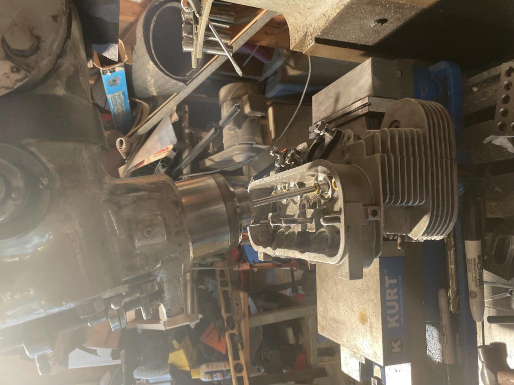
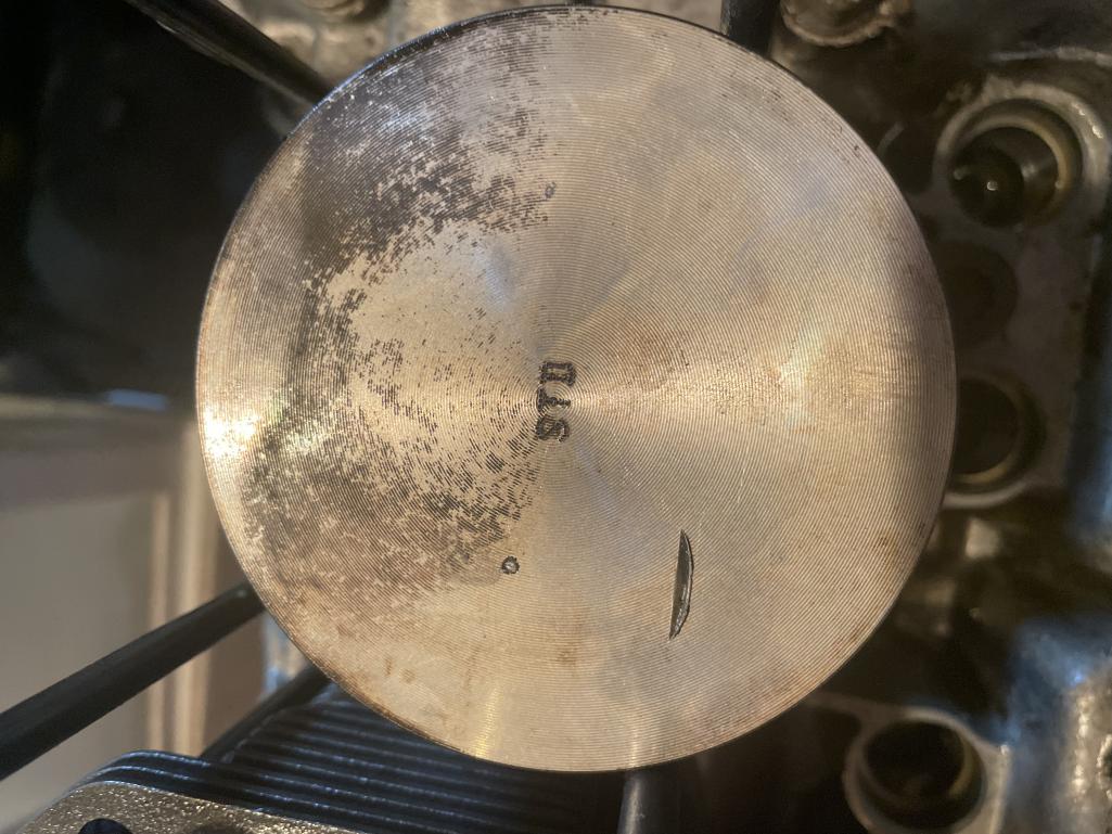
Posted by: rfinegan Oct 4 2021, 04:10 PM
piston set up and fly cut to .050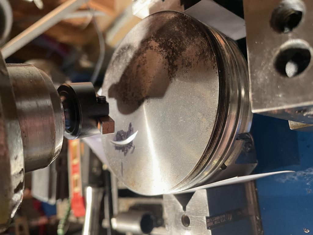
@http://www.914world.com/bbs2/index.php?showuser=209 does this look right? Seem like a small notch compared to pistons that come with reliefs. But gives me the .130 I need
All feedback welcome before I cut the other 3 intakes...I have a lot of clearance on the exhaust side .180 so no notch needed?
Posted by: Dion Oct 4 2021, 04:11 PM
I wish I could fully understand what you just explained! It’s fascinating. Keep it coming.
Enjoying the education. 
Posted by: rfinegan Oct 4 2021, 04:31 PM
@http://www.914world.com/bbs2/index.php?showuser=2766
i better go back and read it again...My brain thinks differently from my keyboard
Posted by: rfinegan Oct 4 2021, 04:37 PM
here is a pick of the play doe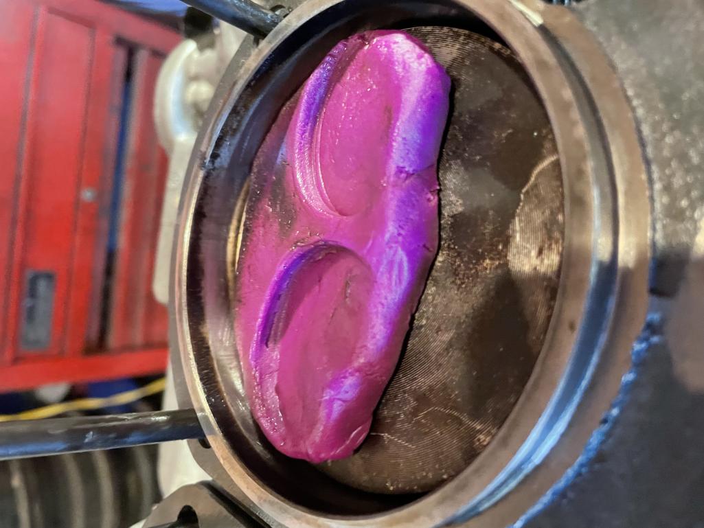
Posted by: rfinegan Oct 4 2021, 04:38 PM
exhaust valve clearance 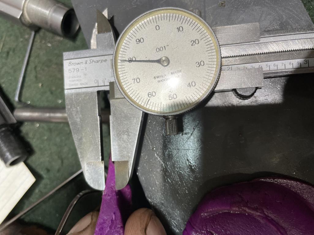
Posted by: Dion Oct 4 2021, 05:02 PM
@http://www.914world.com/bbs2/index.php?showuser=15499 Nope no problem with your writing. It’s just that I’m no engine builder.
I love this stuff . When Dave helped with my 2056 build a while ago, i found the process
totally enjoyable. You have a great skill set.
Posted by: rfinegan Oct 4 2021, 05:23 PM
set up
pic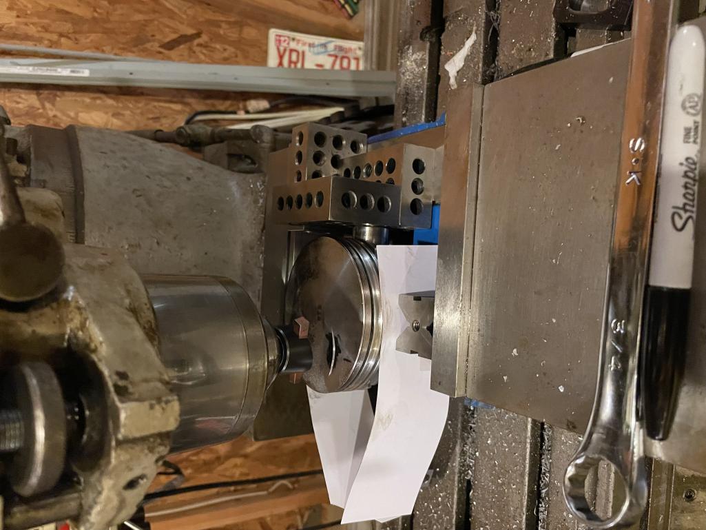
Posted by: Jamie Oct 4 2021, 05:33 PM

set up
pic
The arc of the fly cut is a curve, but notice the ding in the old piston is flat across the base, like the face of the valve. I'm no machinist, but you need to cut a flat across the fly arc to give safe relief.

Posted by: PatMc Oct 4 2021, 06:58 PM
set up
pic
The arc of the fly cut is a curve, but notice the ding in the old piston is flat across the base, like the face of the valve. I'm no machinist, but you need to cut a flat across the fly arc to give safe relief.
Without knowing the shape or relief in the cutting tool, it's tough to figure out what we're looking at. The cutting tool needs to effectively be a chunk of HSS with a radius slightly greater than the fillet radius on the valve. I think what we're seeing on the inside radius of that arc is where the brazed carbide stops, or it's not aligned with the tool shank...and it needs to be for this operation to work. I would personally just use a 1 7/8" endmill for this....but mostly since I happen to have one in the drawer. lol.
Posted by: rfinegan Oct 5 2021, 03:46 AM
I see the problem now, I should have locked the Knee and cut with the quill. NOT the other way around. DOH!
I may have missed my mark.
Posted by: rfinegan Oct 5 2021, 09:57 AM
I made a valve notch cutter out of an Old AMC intake valve 1.97 and turned it down to 44 mm + .100 inch= 1.835 and radiused the outside edge. For the cutting I glued a 80 grit grinding disk to the valve face and trimmed to the diameter. One time use for each valve. Now I can cut just the intake pocket no need and have to drag across the piston to make a trough that is not needed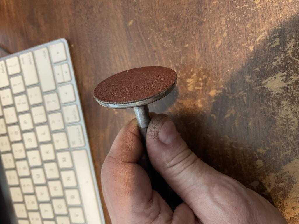
Posted by: rfinegan Oct 5 2021, 10:01 AM
Practice cut look in good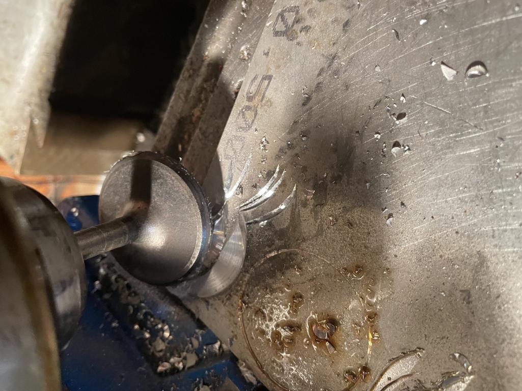
Now I just need to find the centerline of the valve guild (transfer at TDC with head and piston mock up) and a pencil down the valve guide. Then plunge cut with the Quill . Just like a valve opening or using the head as a guide to cut out the notches witha spinning valve. TO bad its the wrong stem and do not fit the heads
With a bit of luck the previous notch may cut out? NO holding my breath. but 50 buck will get a new piston on the way if needed. I have to order the push rods any how' 
Posted by: barefoot Oct 5 2021, 10:12 AM
Practice cut look in good
Now I just need to find the centerline of the valve guild (transfer at TDC with head and piston mock up) and a pencil down the valve guide. Then plunge cut with the Quill . Just like a valve opening or using the head as a guide to cut out the notches witha spinning valve. TO bad its the wrong stem and do not fit the heads
With a bit of luck the previous notch may cut out? NO holding my breath. but 50 buck will get a new piston on the way if needed. I have to order the push rods any how'
Or you could just re-assemble motor and use the actual valve guide in the head and an electric drill to rotate your abrasive coated valve, would be quick & accurate.
Just insure no swarf gets down to the rings
Posted by: mmichalik Oct 5 2021, 10:20 AM
I'm absolutely fascinated by all of this and wish I could follow it. It's so beyond my skill set right now, I just stare at everything and say to myself "ummmm, duhhhhhhh" Thank you for posting it. It really gets me thinking.
Posted by: rfinegan Oct 5 2021, 11:04 AM
@http://www.914world.com/bbs2/index.php?showuser=15673 problems with useing the heads:
1) 2 of my intake valve guides are damaged by the bent valves and had top beat the valves out of the guilds.
2) The "Larger" +.100 AMC cutters are the wrong stem size (Too big) and do not wish to wait till the heads are repaired and tear them apart to use as grinding jigs. Turn them down to fit? Not worth the risk to damaging the good (NEW guides)
GOOD tips...Thanks
-Robert
Practice cut look in good
Now I just need to find the centerline of the valve guild (transfer at TDC with head and piston mock up) and a pencil down the valve guide. Then plunge cut with the Quill . Just like a valve opening or using the head as a guide to cut out the notches witha spinning valve. TO bad its the wrong stem and do not fit the heads
With a bit of luck the previous notch may cut out? NO holding my breath. but 50 buck will get a new piston on the way if needed. I have to order the push rods any how'
Or you could just re-assemble motor and use the actual valve guide in the head and an electric drill to rotate your abrasive coated valve, would be quick & accurate.
Just insure no swarf gets down to the rings
Posted by: rfinegan Oct 5 2021, 01:30 PM
I am going to walk through this process One MORE TIME! Well I get to do it 4 times for the intakes( and 4 for the exhaust if needed)
1)Remove valves from head and assemble with torque spec
2)Rotate crankshaft to TDC (see degree wheel )
3)Insert pencil to mark centerline of valve on top of piston
4)Center punch center line location for Posterity
5) Using V blocks mount piston to vice with business cards to protect
a) Use the piston pin to parallel blocks ensure the piston in pin is perpendicular to the vice
6) Center the Quill to the reference valve center line in piston and lock the X/Y tables
7) Insert cutter in collet and check location for cut
8) Plunge cut with short pecking motion to cut valve relief notch to desired depth ( used .050")
It does not look like much of a notch but the .080 valve clearance I had, Plus the .050 clear once cut should yield a toll clearance of 0.130 on the intake
HELP NEEDED:
How deep can I safely cut may valve notch before the crown is too thin?
The Keith black 96 pistons seem to measure a crown thickness of 0.220 and removing .050 gives me the minimum thickness of. 0.170
I am worried I need to take a deeper cut as the valve may have been in the mechanical notch made when the piston Kissed. Sure I will measure again and once more when the heads are done but would be nice to cut this one to depth and me to the next one
Posted by: rfinegan Oct 5 2021, 02:04 PM
I just got off the phone with UEM the manufacture of the KB 96 pistons for the 2056 at EMW (only). They confirmed the min crown of 0.160 is a good place to respect and will be OK. So all good...
Here are some pics of the Process ...
Location of the Centerline of the Intake valves at TDC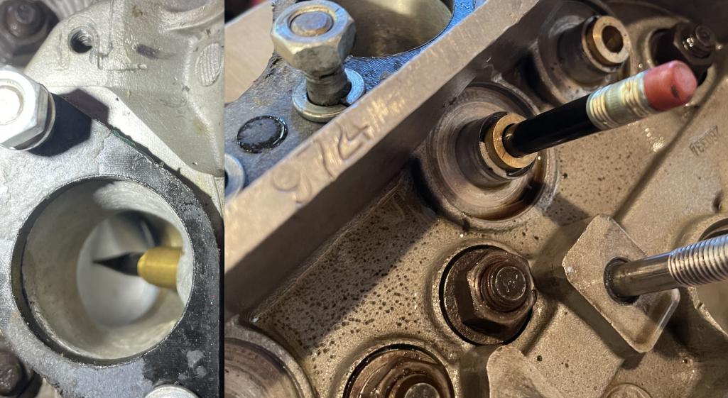
Posted by: rfinegan Oct 5 2021, 02:06 PM
center punched locators on piston tops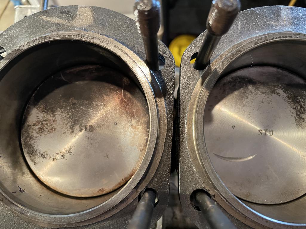
Posted by: rfinegan Oct 5 2021, 02:07 PM
Piston set up on valve center to Centerline of Quill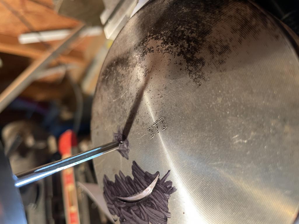
Posted by: rfinegan Oct 5 2021, 02:08 PM
Cutter and finish cut to .050 pocket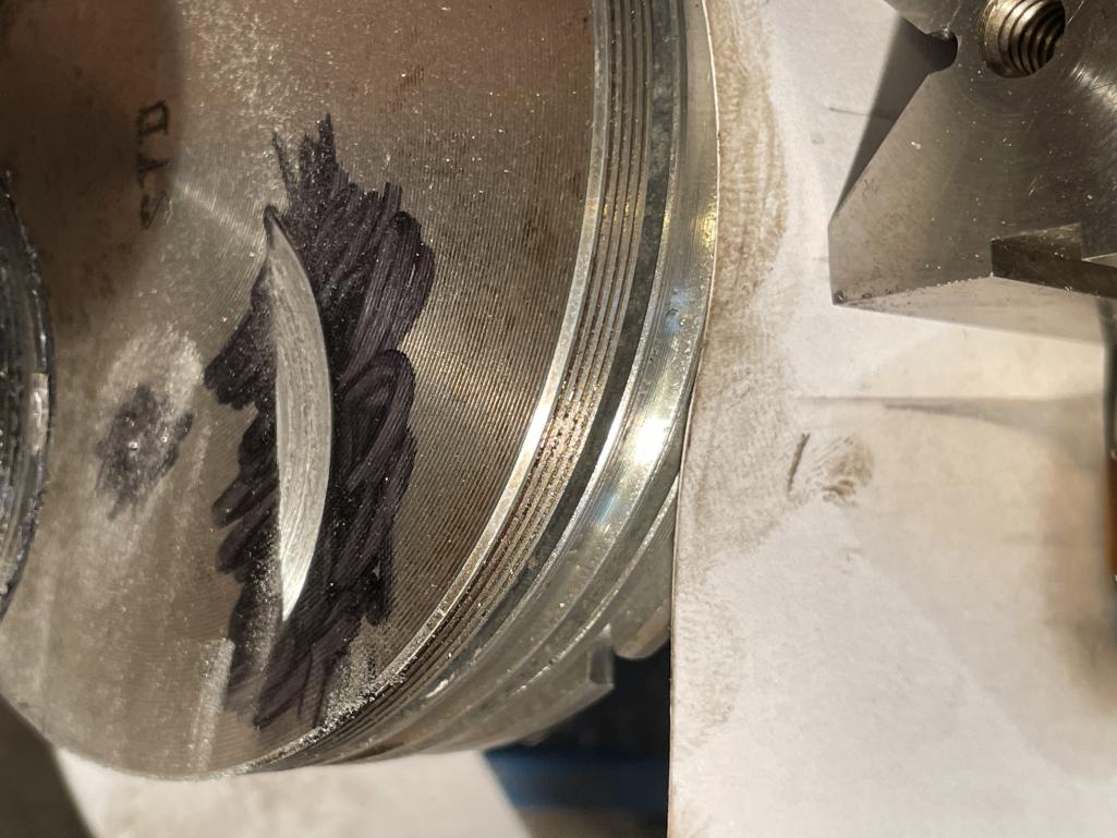
Posted by: rfinegan Oct 5 2021, 02:10 PM
Now you too, have the information and skills to Valve notch your own pistons!
Only 3 more to go...
Posted by: PatMc Oct 5 2021, 05:10 PM
Now you too, have the information and skills to Valve notch your own pistons!
Only 3 more to go...
...and that's why I always angle the workpiece (if at all humanly possible) and not the quill....I've made that mistake a few times.
Nicely done.
Posted by: ChrisFoley Oct 6 2021, 06:09 AM
I made a fixture to hold pistons at the correct angle rather than reposition the quill.
While I generally wouldn't use abrasives like that on a milling machine, your process is certainly adequate to make small eyebrows. Looks good.
Did you measure the intake clearance with playdoh on one of the unaffected pistons?
I'm also curious if maybe the problem was initiated by valve guides that were too tight, and not an over-rev.
Posted by: rfinegan Oct 6 2021, 07:51 AM
Final Clearance measured on # 1 cylinder . ( small smile fail) with dial indicator
Intake @ 10 degree first opening. 0.150 in min piston to valve clearance
Exhaust 10 degree before closing. 0.118 in min piston to valve clearance
I think that was correct ( I put tape on degree wheel as reference)THIS IS THE CLOSEST MEASUREMENT
I also pulled the swivel feet and put regular adjusters in set to Zero lash. This was to ensure the feet were not binding and increasing the lift? I will ensure the clearance to the rocker when going back together after new valves and check that the geometry is correct too
@http://www.914world.com/bbs2/index.php?showuser=209
Next:
I will measure the Clearances on # 2 cylinder ( this is a no fail Cylinder ) for a before and after comparing and notching
BTB:
1) Both rear cylinders were Intake failures
2) Both intake failures shared the same come lobe
3) Both rear cylinders get hotter? # 3 gets the hottest
4) #3 intake had the most damage and severe Valve bend (Stuck valve)
5) #1 intake kissed but opens and closes (sticks some times ) perhaps a smaller bent valve
Posted by: ChrisFoley Oct 6 2021, 09:40 AM
How much larger is the eyebrow radius than the valve head? It should be at least a couple mm.
Posted by: rfinegan Oct 6 2021, 10:38 AM
Radius is .050 larger.
Or added .100 to the diameter for the valve 1.832 ( 44 mm valve 1.73228)
How much larger is the eyebrow radius than the valve head? It should be at least a couple mm.
Posted by: rfinegan Oct 6 2021, 02:25 PM
I did a valve to piston check on Cylinder 2 both intake and exhaust...
Intake piston to valve has a min clearance of 0.100 in
Exhaust piston to valve has a min clearance of 0.110 in
I wish the numbers we a perfect match for each cylinder, but I am sure the valve geometry has something to do with the Max lift.
or
The Deck height
Cylinder 1= 0.037 in
Cylinder 2= 0.040 in
The #2 intake of .100 + .050 notch relief=.150. this is the same or very close the the results above
Posted by: 930cabman Oct 6 2021, 05:23 PM
Are your valve springs up to the task?
Posted by: rfinegan Oct 6 2021, 08:16 PM
Yep,
Brand new double spring/HD springs
retainers/keepers
New SS Valves
Seats
Guides
mild porting
cut chambers
57 cc for 9.0:1 compression at .040 deck
all the good stuff
should handle the SS 44/38 valves well above 6k
-Robert
Are your valve springs up to the task?
Posted by: rfinegan Oct 7 2021, 03:53 AM
Raby Cam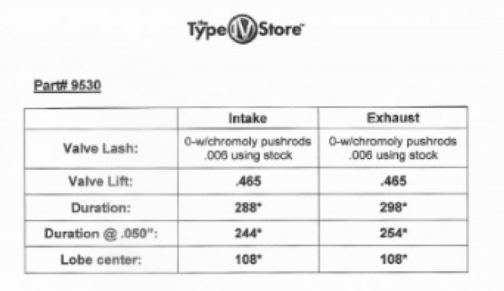
Posted by: rfinegan Oct 7 2021, 04:56 AM
Ha haaaa...
Posted by: 930cabman Oct 7 2021, 06:46 AM
Thanks for reporting with this good information. Conclusion: .100/.110 is not enough clearance?
Posted by: rfinegan Oct 7 2021, 07:19 AM
@http://www.914world.com/bbs2/index.php?showuser=24877
Racer Chris comment in the past that 0.120 on intake and 0.080 on exhaust is desired. Other internet research said:There are some racers who go as low as 0.060 and others say the exhaust have to be lager clearance for thermal expansion. Who knows?
I am still not sure of the root cause here. Other than the obvious , "Kiss" of the valves to piston.
1)Over Rev? Was running good before 3k rev to set timing (Occasional Spark knock)
2)Sticking Valve: Guide to tight
3)Previous over Rev: Slight kiss to bend valve and tighten valve guide. Causing sticking valve and collision with piston ( never hit rev limiter 6500)but engine has seen over 6k on strong pull
4) Oil temp never above 240*f. Stock gauge estimate 3/8" from red (350) mark when running hard
Notching for the valve relief is EZ with engine apart. Other then a slight drop in compression and perhaps a little change in the Quench area it should have little negative impact.
I do plan on re-balancing the Pistons when I am done...
Should I also open the clearance for the Exhaust side too? With a smaller notch for the smaller exhaust valve?
Lets see where this thread takes us...
-Robert
Thanks for reporting with this good information. Conclusion: .100/.110 is not enough clearance?
Posted by: rfinegan Oct 7 2021, 04:10 PM
One good things about grinding/sanding the valve notch is the rounded radius. No sharp edges or very few...
Within a 0.10 of a gram of each other. ( I was a little bored) and worthless till the other 2 are done!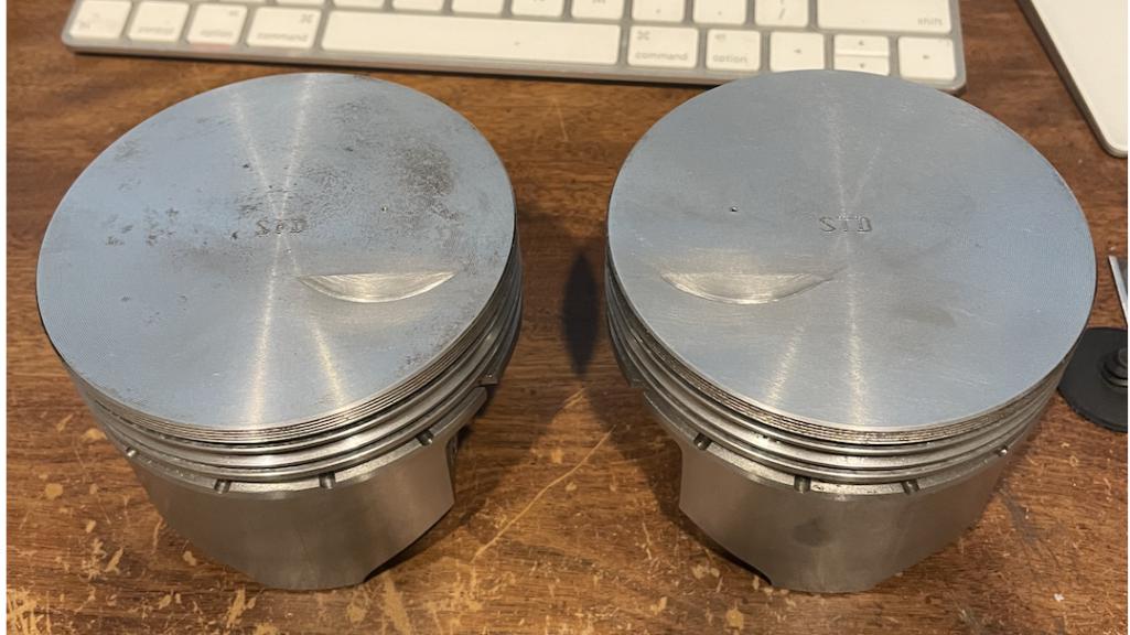
Posted by: maf914 Oct 7 2021, 04:41 PM
rfinegan,
Thanks for posting your engine build and these latest piston valve notch details. While I understand what you are doing I have nowhere near the skill to do detail work like this, nor the equipment to do it. I really would like to see you put this thing back together and say that it is running great.
One thing I was wondering is that when you do the valve notch do you then polish the piston top and valve notch to eliminate possible sharp edges that might cause hot spot pre-ignition? That just some stuff I remember from engine build magazine articles. 
Posted by: rfinegan Oct 7 2021, 05:04 PM
@http://www.914world.com/bbs2/index.php?showuser=632
Thank you for the encouragement. There will be a Dyno day in my future! I hope it will be before the new year.
As for the sharp edges and preignition and hot spots, you are correct. Same with the stress risers on sharp milled edges. They need to be radiuses too. I was referencing this a little as I used grinding/sanding and not a Cutter to make my notches. It is what had/could make . But it does make for softer edges. A bit harder to make things repeatable for volume depth and weight. But EZ to take a few 0.10 of a gram out for final balancing.
For those wondering how to get the depth correct on an angle quill? MATH?
I do not know either.
No DRO (digital read out) here. So I got out my feeler gages. Or more correctly Wire Spark plug gages. I selected the 0.50 wire gage and lay it flat along the milled pocket at the deepest. I guest a straight edge razor blade across the piston top to feel for it to catch. I continued to cut till the razor no longer catches on the gage. Then some sanding sticks to clean up and radius.
Posted by: rfinegan Oct 8 2021, 11:42 AM
FROM THE WEB:
According to WebCam the minimum clearance is .050 for the intake and .080 for the exhaust.
Massive T4 says do not go below 0.080
Here is a video of cutting the Intake valve notch
https://www.youtube.com/watch?v=E99SJnPKX4k
Posted by: rfinegan Oct 8 2021, 01:38 PM
I am not convinced my clearances were an issue. But an ounce of preventions they say....
I did find my Deck height is the following:
1) =0.037
2) =0.040
3) =0.040
4) =0.037
Each valve notch is 0.050 and is indexed off the Center line of the valve guide
Piston weight in at less than .5 gram of each other with piston pins installed
Valve to piston clearance
Was
Intake 0.100
Exhaust = 0.110
Math calculation. Old + 0.050= Total clearance
NOW:
Intake = 0.150
Exhaust = 0.160
I will measure real clearances again once the heads are repaired...
But for now....
Thank you to all that contributed and checked in on this thread
Best Regards
-Robert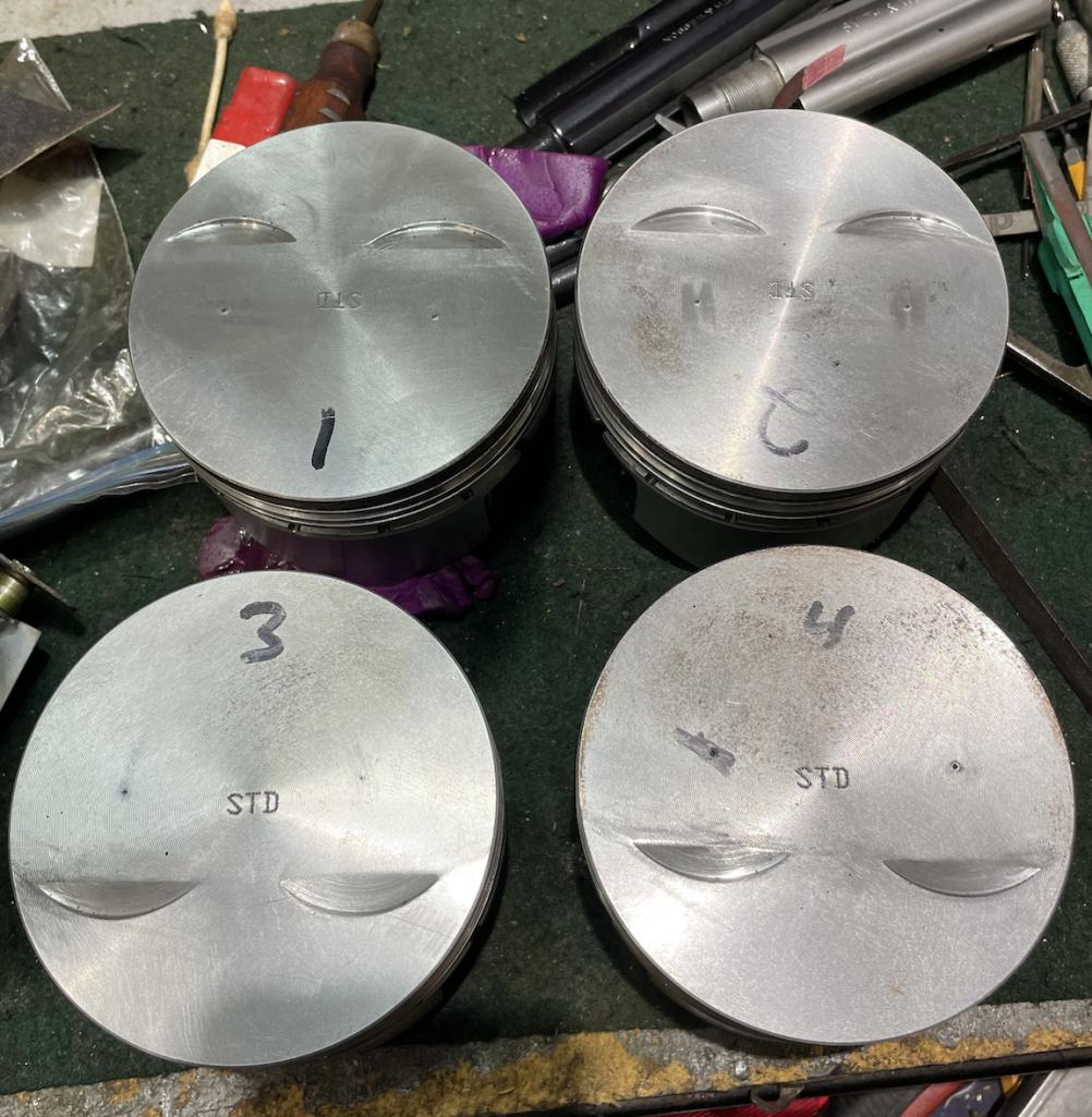
Powered by Invision Power Board (http://www.invisionboard.com)
© Invision Power Services (http://www.invisionpower.com)