Printable Version of Topic
Click here to view this topic in its original format
914World.com _ 914World Garage _ OT: A little carried away…
Posted by: Van B May 17 2022, 09:05 PM
I set out to build an engine plate that I could work from, but it quickly developed a life of its own lol.  There’s a reason behind the design of every part, but I also set out to work with materials I had on hand along with some steel sourced from Home Depot.
Attached thumbnail(s)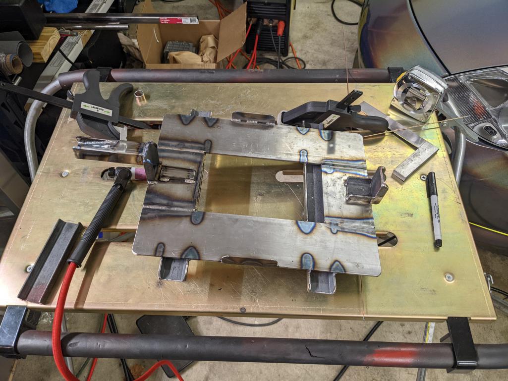
Posted by: Van B May 17 2022, 09:06 PM
Bottom
Attached thumbnail(s)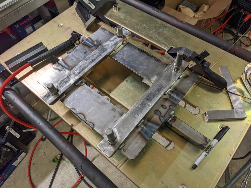
Posted by: Van B May 17 2022, 09:07 PM
Installed
Attached thumbnail(s)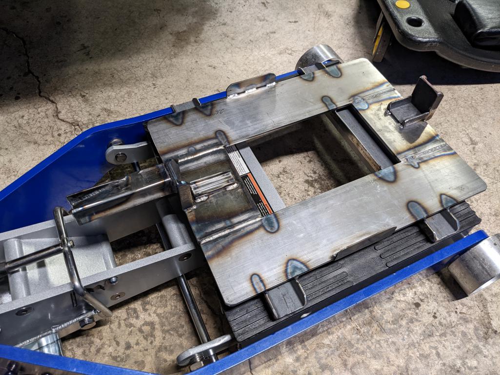
Posted by: nditiz1 May 17 2022, 09:08 PM
Sweet! What is this for again?
Posted by: Van B May 17 2022, 09:09 PM
To drop the engine. But it will hold the engine nice and stable so I can do work while it’s on the jack.
Posted by: r_towle May 17 2022, 09:12 PM
What is touching the motor?
Looks cool, but I’m not sure how it works or limits access.
Posted by: Van B May 17 2022, 09:14 PM
I’ll get a picture of it on the motor tomorrow. But it fits like a glove and allows access to everything. The only thing I can’t do is split the case, for obvious reasons.
Posted by: wonkipop May 17 2022, 09:41 PM
i like the way you can elevate to comfortable working ht and sit on a chair?
Posted by: Van B May 17 2022, 09:53 PM

i like the way you can elevate to comfortable working ht and sit on a chair?
Exactly. Sitting height and 360 access.
I plan on putting the 996 in storage for a month (probably more) while I do this so, I’ll have the motor on on one side of the garage and the chassis on the quick jacks on the other.
Posted by: wonkipop May 18 2022, 12:03 AM
i like the way you can elevate to comfortable working ht and sit on a chair?
Exactly. Sitting height and 360 access.
I plan on putting the 996 in storage for a month (probably more) while I do this so, I’ll have the motor on on one side of the garage and the chassis on the quick jacks on the other.
since you are preparing to sit in a comfy chair while tearing things apart - i found this scanning through the tech bulletins/wealth of info that @http://www.914world.com/bbs2/index.php?showuser=104 has on his website.
i asked mike about it. he said d-jets were known for roaring on cold start up (he was talking about the mercedes benz since no real numbers of d jet porsches ever in aus). said he wasn't surprised at tech bulletin - they would have been trying to address emissions on a cold start by the time they got to L jet and were out to calm things down.
net result - a bit of age and aav wear/decline and you get into the problems we had/have with weak idle. his guess was 1200 +/- 50 is probably around about where cold idle is meant to be during warm up.
Posted by: emerygt350 May 18 2022, 06:09 AM
Very nice. Can't wait to the motor out and cleaned up.
Posted by: Krieger May 18 2022, 07:26 AM
Very cool! Is that a motorcycle lift? Will you be able to take out a complete engine and trans assembly?
Posted by: Van B May 18 2022, 07:51 AM
Here is is fitted to the engine.
The rear mill tab is the no slop mount point and I have progressively more movement toward the front. This should allow me to give enough shimmy as I pull the transmission off. I also use the side protrusions as a fixed point to allow a bit of up and down pitch movement. Less than 1cm in yaw and pitch, but I think that will be enough.
For the transmission tang, I made a ramp style to help guide the transmission in and out while also adding a bit of support.
@http://www.914world.com/bbs2/index.php?showuser=2104 The lift is the harbor freight motorcycle/ATV lift. I liked the wide base and the center opening allows access to the drain plug and screen.
The whole plate is pitched forward to help with CG and the rods that interface with the lift are meant to bind if the engine tries to rock back.
Attached image(s)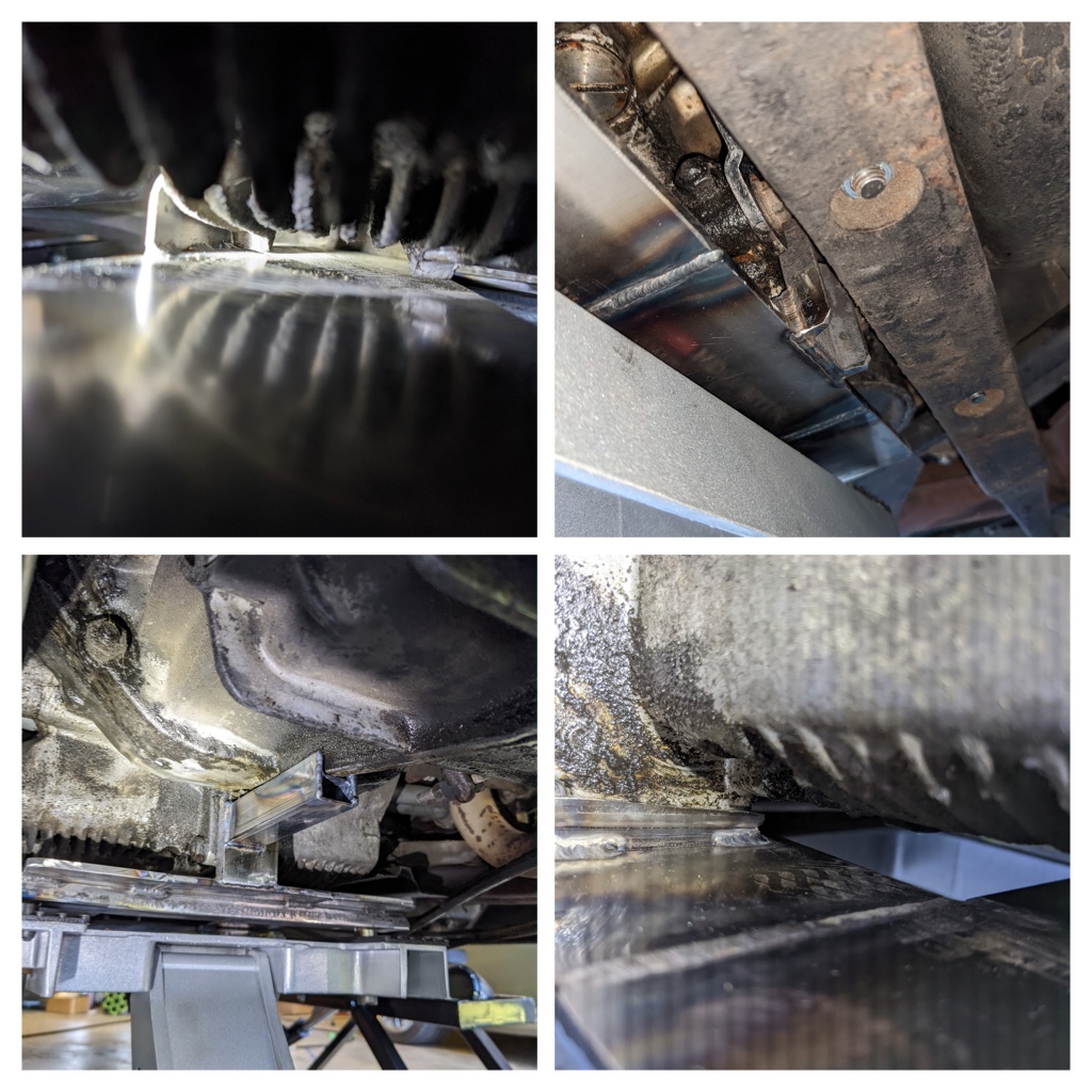
Posted by: Van B May 18 2022, 07:59 AM
@http://www.914world.com/bbs2/index.php?showuser=24231 I now get a solid 1400RPM when the AAV is wide open. When the engine is a normal cold start, it hangs around 1200. But because the shape of the disc in the AAV allows more air right up until it closes completely. The idle stays a little high until the engine is fully warm (1000-1100RPM).
Overall, I think the FI is sorted. What I need to do now is fix all the massive oil leaks from these 50yr old seals. I also intend to sort out the fuel lines, fuel pump, and hav the throttle body rebuilt.
Posted by: Root_Werks May 18 2022, 10:00 AM
Looks damn cool to me! Nicely fabbed.
Posted by: wonkipop May 18 2022, 08:28 PM
@http://www.914world.com/bbs2/index.php?showuser=26011 very neat the way it works in those photos.
something you might be interested in doing when you have the engine down is installing an oil temp sensor wire to plug into that little plug in the upper engine bay.
after that info came to light regarding that plug i guessed wrong as a cht lead on the other guys car, i looked into the hook up for a temp gauge. its not plug and play on our 1.8s like a 2.0 was.
i posted up some additional material in the EC engine thread in originality section of the site. its got some photos of the wire routing and the little stand off clips that support the wire. the clips hook up the oil filter support tube and one of the oil cooler brackets.
be handy to have that in place if you ever do an oil temp gauge.
there is a nice way to do the temp in the left hand combo instrument in the binnacle.
replaces the hand brake idiot light. its the standard gauge that went in 2.0 L cars.

Posted by: Van B May 18 2022, 08:34 PM
Yeah our cars have all the wiring for a center console, it’s just missing the probes. I have OE gauges I bought from Tom B right after I purchased the car. But after having it a while I want to keep the floor open and find some way to put those three gauges in that keep the floor clear…. While still looking like OE.
Posted by: wonkipop May 18 2022, 09:23 PM
Yeah our cars have all the wiring for a center console, it’s just missing the probes. I have OE gauges I bought from Tom B right after I purchased the car. But after having it a while I want to keep the floor open and find some way to put those three gauges in that keep the floor clear…. While still looking like OE.
its missing the bit of wire from the probe too - will pop out of upper surface of engine tin, through the accelerator cable hole i think. i can't see any evidence the wire is installed on mine nor the little stand off crimp clips but i need to get it on a hoist to really look up in there behind the fan casting from below. don't believe its there in our 1.8s. just the wire that pops out of loom and in mine was still tucked up under battery area. good thing you alerted me to that one, was wondering how it could be "plug and play" as jeff bowlsby suggested. it sort of is, but there is nothing to plug into on the engine.
Posted by: r_towle May 18 2022, 09:27 PM
Looks cool
Pull the motor and please let’s here how it goes.
Posted by: Van B Sep 19 2022, 08:20 PM
More shenanigans!
Now of that I’ve committed to blasting the pitted areas of the engine bay, I’ve introduced another problem to solve… dry air.
To solve this problem, I’ve decided to use the most labor intensive and over complicated solution I can; a TIG welded copper manifold that connects to an air filter and desiccant dryer. I’m calling the manifold Donkey Kong for reasons that should be apparent by tomorrow when I finish it up.
I got all the pieces cut and laid out according to the blueprint that lives in my mind somewhere between logic and fantasy. Then start with the welding… which looks nice at first lol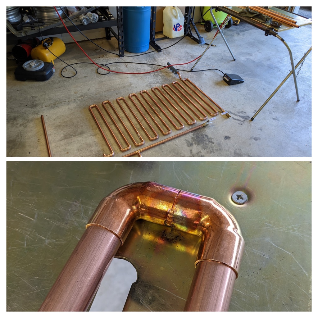
Then oxidation kicks into gear lol. Yes I know soldering would’ve been faster, easier, and preserve the temper. But I’m going after an aesthetic too ya know?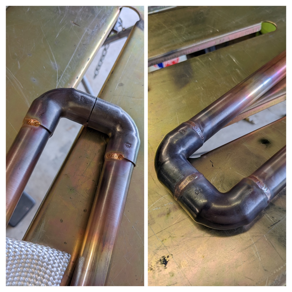
For removing the oxidation I have my own secret sauce electro polishing solution I made. It’s mainly phosphoric acid with a little oxalic and sulfuric acid added for flavor. I quench the part in the acid, rinse off the scale, and re-submerge for a couple min of electrolysis action.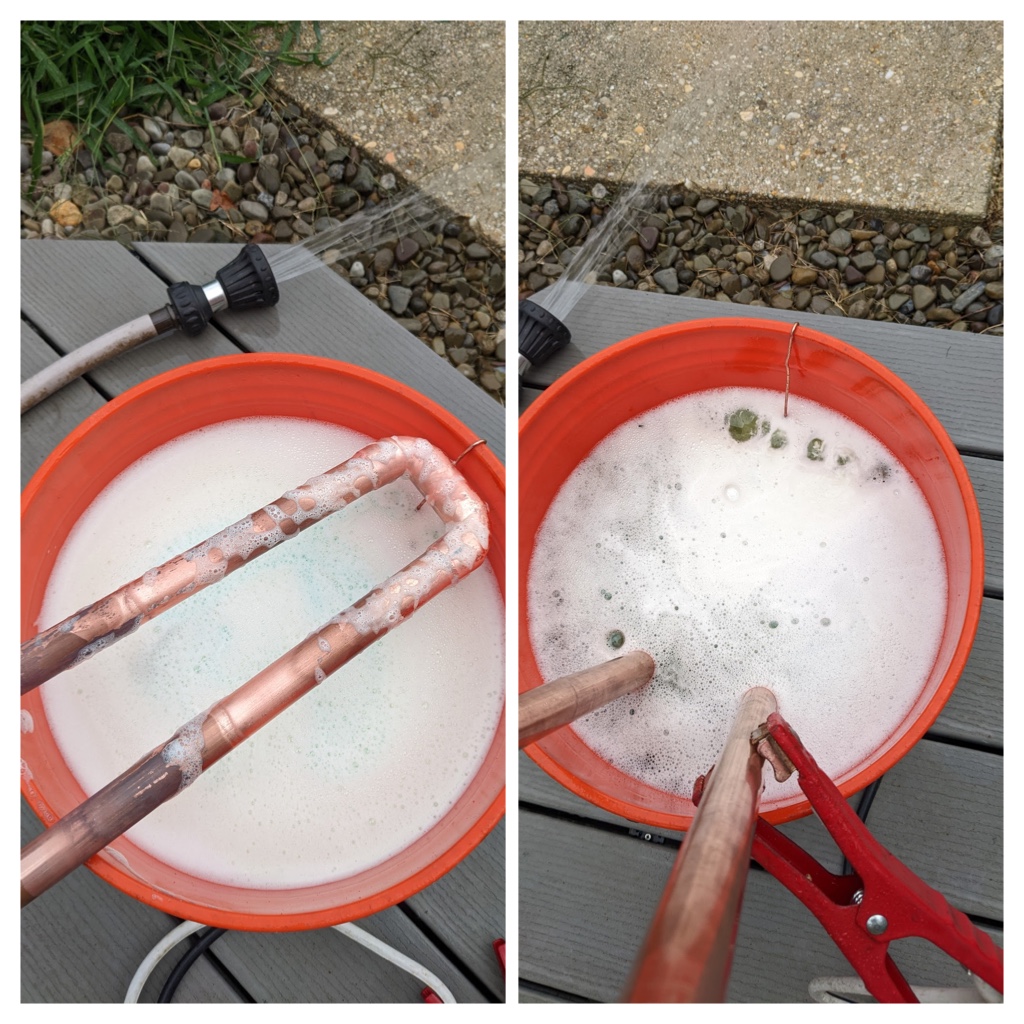
After all the oxidation is removed, I give it a scotchbrite rub and onto the next one. The angle you see will make more sense tomorrow 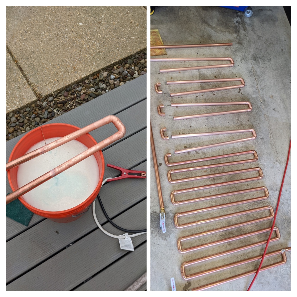
Posted by: wonkipop Sep 20 2022, 01:45 AM
what are you building. a hydronic radiator?? 
Posted by: Van B Sep 22 2022, 01:49 PM
I present, The Donkey Kong manifold lol!
Attached thumbnail(s)
Powered by Invision Power Board (http://www.invisionboard.com)
© Invision Power Services (http://www.invisionpower.com)