Printable Version of Topic
Click here to view this topic in its original format
914World.com _ 914World Garage _ Attention Electrical Gurus
Posted by: bbrock Jul 28 2022, 07:17 PM
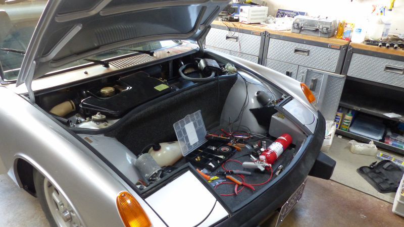
Right after ordering a complete http://carmagic.us/washer.html to convert my windshield washer to electric, I read http://www.914world.com/specs/tech_el_washer.php. The idea of pulling power for the washer pump off the intermittent wiper feed so the washer is activated by pulling back on the wiper lever was too elegant not to try.
I happened to have this nifty vintage VW style splitter I bought some time ago for not other reason than I thought it might come in handy for some future custom wiring project. It was just the ticket for splitting off of my intermittent washer relay to power the washer pump.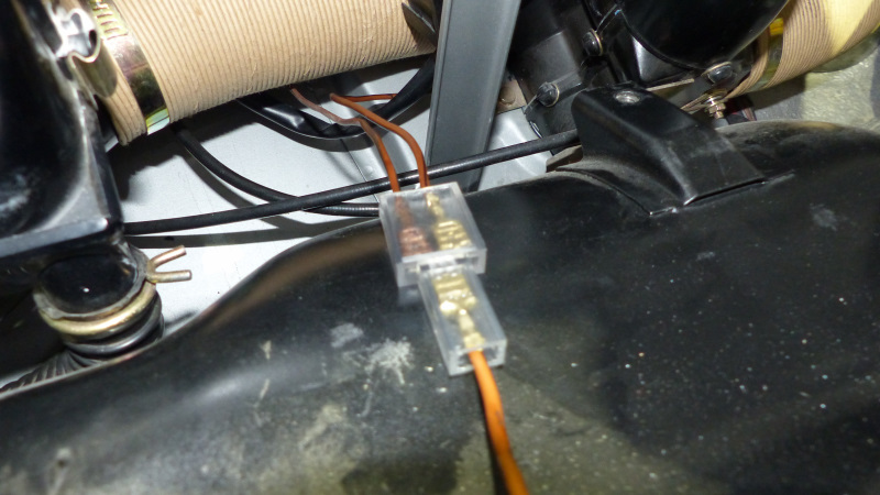
After hooking everything up, I pulled back on the wiper lever and HUZZAH! The washers squirted and the wipers ran for two sweeps and parked. Pretty slick! I couldn't understand how the intermittent wipers would work when the lever was pulled down to turn the intermittent wipers on. I pull down on the lever to test them and nothing. As soon as I unplug the washer pump, the intermittent wipers start running. I'm not sure how the intermittent relay works, but thinking the timer is from charging a capacitor which then "bump starts" the wipers to run a single cycle.
Is there is a reasonably simple way to isolate the pump so it allows the intermittent mechanism to run without activating the washer pump? Could be a fun project. Or should I just go back to the original plan of installing the Car Magic switch? I just like the idea of minimizing the wiring.
Posted by: Spoke Jul 29 2022, 09:20 AM
@http://www.914world.com/bbs2/index.php?showuser=20845
Do you have documentation describing the wiring? I'm not familiar with the kit.
Posted by: bbrock Jul 29 2022, 10:04 AM

@http://www.914world.com/bbs2/index.php?showuser=20845
Do you have documentation describing the wiring? I'm not familiar with the kit.
@http://www.914world.com/bbs2/index.php?showuser=3031
I'm not actually using the kit. The kit is pretty straightforward. It is a microswitch that replaces the stock plunger valve on the wiper switch and then feeds 12v to the washer pump via a relay. Simple enough, but requires drilling the wiper switch assembly to accommodate the micro switch and running more wire from the microswitch and fuse box to the relay, and relay to the washer. It is simpler and more accessible to do the whole install under the cowl of the car, and I think, more elegant.
Instead of the kit, I'm branching off the brown/black wire that feeds power to the intermittent relay for cars that have them. 12v is fed to that wire whenever the wiper lever is pulled back for manual pulse wipers, or down into the intermittent position. Works great when I pull the lever back for pulse. With the lever down for intermittent, it seems to be bleeding current to ground through the washer motor and screwing up the timer circuit on the intermittent relay. It would be cool if there was a fairly simple circuit that sends current to the pump when the wiper lever is pulled back, but not when the lever is pulled down. I'm pretty good at building circuits, but less so at designing them.
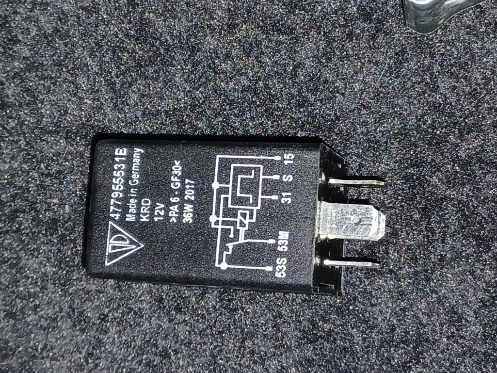
Here is a link to https://bowlsby.net/914/WiringHarnesses/docs/WiperIntervalRelay_Instructions.pdf and discussion of running a washer pump off it on the last two pages. And below is a pic of the relay I'm using.
Posted by: dr914@autoatlanta.com Jul 29 2022, 11:02 AM
intermittent is activated by pulling the stalk down one below off, washer is activated by pulling the stalk towards you
Right after ordering a complete Car Magic kit to convert my windshield washer to electric, I read http://www.914world.com/specs/tech_el_washer.php. The idea of pulling power for the washer pump off the intermittent wiper feed so the washer is activated by pulling back on the wiper lever was too elegant not to try.
I happened to have this nifty vintage VW style splitter I bought some time ago for not other reason than I thought it might come in handy for some future custom wiring project. It was just the ticket for splitting off of my intermittent washer relay to power the washer pump.
After hooking everything up, I pulled back on the wiper lever and HUZZAH! The washers squirted and the wipers ran for two sweeps and parked. Pretty slick! I couldn't understand how the intermittent wipers would work when the lever was pulled down to turn the intermittent wipers on. I pull down on the lever to test them and nothing. As soon as I unplug the washer pump, the intermittent wipers start running. I'm not sure how the intermittent relay works, but thinking the timer is from charging a capacitor which then "bump starts" the wipers to run a single cycle.
Is there is a reasonably simple way to isolate the pump so it allows the intermittent mechanism to run without activating the washer pump? Could be a fun project. Or should I just go back to the original plan of installing the Car Magic switch? I just like the idea of minimizing the wiring.
Posted by: FlacaProductions Jul 29 2022, 11:53 AM
As George says - but do you have the tab broken out that allows the wiper lever to actually, physically move down below the OFF position?
Posted by: bbrock Jul 29 2022, 12:45 PM
Let's back up a bit. My intermittent wipers work perfectly fine. They work exactly as they are supposed to until I try to power my NEW electric washer pump from the brown/black wire on the main chassis harness that feeds power to the intermittent relay. When I connect the washer pump, the washer works like a champ when I pull the lever on the stalk towards me, but the intermittent does not work pulling the lever down. This is not the factory configuration but would make for an easier, cheaper, and more elegant conversion to electric washers if I can make the whole system work.
BTW - I love the absurd stupidity of the tire operated washer system and really tried to get mine working again. All of the washer valves that fit into the wiper switch assembly I have are either seized up or leak. That includes a new aftermarket one I bought from CIP which is a steaming pile of  . So... reluctantly I am converting to electric and being quite picky about how I do it as usual.
Posted by: lesorubcheek Jul 29 2022, 01:45 PM
It's kinda difficult looking at the wiring diagrams alone to tell exactly what's making continuity when the lever is pulled. Makes sense because there's no electrical connection normally associated with a 914 when pulling back on the lever, except maybe with the intermittent feature. Mr. Bowlby does say in the article he's only heard using the S1 to S brown and black wire may work, so it may well be the parallel load added with the pump is causing the normal operation of the intermittent wipers to fail, yet it does work as expected for pulling back to get a quick squirt.
This is just a guess, but if you look at a 911 diagram for actuating the pump, it uses connector 53c off the wiper switch. I don't have access to a 914 switch and wiring right now, but the 914's diagram does show a 53c off it's switch, just not connected to anything. If, and it's a big if, 53c actually has a pass through wire, it may be worth trying for the pump connection. That way it wouldn't interfere with the normal intermittent function when in the down position. If there's no wire coming off of 53c, then it may be too much trouble to even think about fooling with it, but if there's a wire, I'd get a meter and see if it gets 12V when the lever is pulled. If so, it'd just require extending a wire to reach the pump. Again, just an idea, and it may well all be a wild goose chase, but it's an intriguing problem.
Best of luck,
Dan
Posted by: bbrock Jul 29 2022, 04:52 PM
It's kinda difficult looking at the wiring diagrams alone to tell exactly what's making continuity when the lever is pulled. Makes sense because there's no electrical connection normally associated with a 914 when pulling back on the lever, except maybe with the intermittent feature. Mr. Bowlby does say in the article he's only heard using the S1 to S brown and black wire may work, so it may well be the parallel load added with the pump is causing the normal operation of the intermittent wipers to fail, yet it does work as expected for pulling back to get a quick squirt.
This is just a guess, but if you look at a 911 diagram for actuating the pump, it uses connector 53c off the wiper switch. I don't have access to a 914 switch and wiring right now, but the 914's diagram does show a 53c off it's switch, just not connected to anything. If, and it's a big if, 53c actually has a pass through wire, it may be worth trying for the pump connection. That way it wouldn't interfere with the normal intermittent function when in the down position. If there's no wire coming off of 53c, then it may be too much trouble to even think about fooling with it, but if there's a wire, I'd get a meter and see if it gets 12V when the lever is pulled. If so, it'd just require extending a wire to reach the pump. Again, just an idea, and it may well all be a wild goose chase, but it's an intriguing problem.
Best of luck,
Dan
All good thoughts and I was thinking along a similar path. I need to spend some quality time with the wiring diagram to understand how it works and if there are other options for tapping 12v for the pump. It's curious to me that there is a different behavior pulling the lever back vs. down given that both are sending 12v through the same wire. I'll take a look at 53c to see if that provides an option too. So close that now I feel like I HAVE to crack this nut.

Posted by: lesorubcheek Jul 29 2022, 07:47 PM
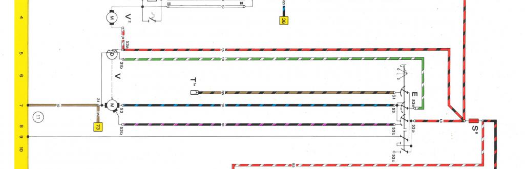
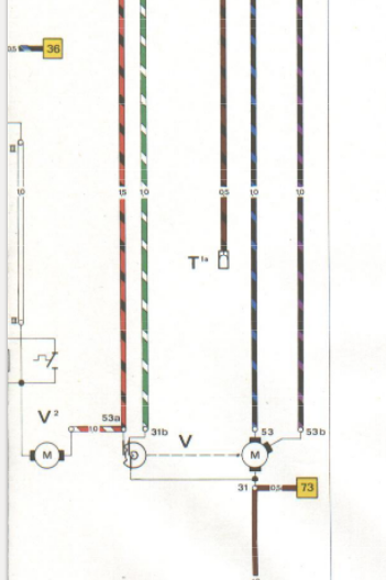
I know the feeling. You just can't let this go without solving it. From the diagram, you can see a connection from a contact on the pull circuit (right 2 contacts) to the input of S1, so you can visualize that just pulling back on the lever will energize the intermittent action, just as 53c should be energized when pulling back on the stalk. 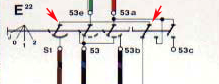
The part I can't visualize from the diagram is what's going on at S1 when the stalk is down or in the J position. It doesn't look like it's connecting to anything if you rock the angle up or clockwise one tick in the diagram. It looks like 53e will connect with 53, just as in the off position, which makes sense as that would connect the output from the intermittent relay to the low speed wiper. I'd expect 53a which is the 12V input to the switch to be connected with S1 when the switch is in the J position..... maybe it is, it just doesn't look clear in the diagram.
Dan
Posted by: Spoke Jul 29 2022, 09:54 PM
@http://www.914world.com/bbs2/index.php?showuser=20845
I'm not sure how pulling back on the stalk energizes the washer as that function was originally a pressure hose going to the tank and tire. On my '74 I replaced that valve with a microswitch and ran a wire to the washer motor. I had to click the stalk down to get the wiper to run.
Posted by: bbrock Jul 29 2022, 10:40 PM
@http://www.914world.com/bbs2/index.php?showuser=20845
I'm not sure how pulling back on the stalk energizes the washer as that function was originally a pressure hose going to the tank and tire. On my '74 I replaced that valve with a microswitch and ran a wire to the washer motor. I had to click the stalk down to get the wiper to run.
Yes, but the trick is that pulling back on the stalk energizes the brown/black S1 wire to run the wipers for two cycles (Sir Andy says it does 4 in his post, but mine does 2). So splitting off the S1 intermittent wire gives you 12v to send to the washer pump when the lever is pulled back. That part works and it pretty darn slick. But when I pull the lever down, I no longer get intermittent action. If you have intermittent on your 74, I'm not sure why the wiper isn't running when you pull back on the lever

Posted by: bbrock Jul 29 2022, 10:52 PM
I know the feeling. You just can't let this go without solving it. From the diagram, you can see a connection from a contact on the pull circuit (right 2 contacts) to the input of S1, so you can visualize that just pulling back on the lever will energize the intermittent action, just as 53c should be energized when pulling back on the stalk.
The part I can't visualize from the diagram is what's going on at S1 when the stalk is down or in the J position. It doesn't look like it's connecting to anything if you rock the angle up or clockwise one tick in the diagram. It looks like 53e will connect with 53, just as in the off position, which makes sense as that would connect the output from the intermittent relay to the low speed wiper. I'd expect 53a which is the 12V input to the switch to be connected with S1 when the switch is in the J position..... maybe it is, it just doesn't look clear in the diagram.
Dan
Here is a better pic of the switch circuit. [Bad info]:
Posted by: bbrock Jul 30 2022, 10:29 AM
My previous post was incorrect. It was dark in the garage when I tested voltage on S1 last night and I failed to notice I was reading mV rather than V. Looking at the circuit diagram again, it looks like S1 is not connected to anything in the J position, and connects to ground in any other position. This is apparently how the intermittent circuit is disabled because if I disconnect S1 (brown/black) wire from the intermittent relay, the intermittent wipers run with switch in the J position, and continue to run in the off position. It also explains why the wire is brown/black which confused me since brown is ground on these cars and brown/white is switched ground. Brown/black might mean it is both a switched ground and switched voltage?
When the lever is pulled back, with the switch in the 0 position, S1 is connected to 53a which is the 12v supply. It's hard for me to tell from the diagram, but I assume S1 is also disconnected from ground at the same time since it would create a dead short otherwise.
This is all starting to make sense now. When the washer pump is connected to S1, it gets 12v when the lever is pulled back and works fine. But when the lever is pulled down into the J position, the washer motor creates a path to ground which prevents the intermittent washers from activating. It seems what is needed is some kind of relay switch circuit so that the path on the S1 (brown/black) where to the washer pump remains open except when there is 12v present. Any ideas on what that circuit should be?
Posted by: Superhawk996 Jul 30 2022, 10:36 AM
I apologize I'm worthless for this thread. All my books, schematics and parts are packed up and are not at hand to analyze or test.
Looks like you're getting closer to solving this.
Hope this doesn't end up needing an Arduino! 
Posted by: bbrock Jul 30 2022, 11:20 AM
I apologize I'm worthless for this thread. All my books, schematics and parts are packed up and are not at hand to analyze or test.
Looks like you're getting closer to solving this.
Hope this doesn't end up needing an Arduino!
Ha ha. Funny because I think doing this via arduino would be fairly simple, but overkill.
Posted by: Superhawk996 Jul 30 2022, 11:38 AM
I apologize I'm worthless for this thread. All my books, schematics and parts are packed up and are not at hand to analyze or test.
Looks like you're getting closer to solving this.
Hope this doesn't end up needing an Arduino!
Ha ha. Funny because I think doing this via arduino would be fairly simple, but overkill.
Can you post a more comprehensive circuit diagram of how you have this wired and what you believe the circuits to be?
I'm wondering if you can utilize the standard Bosch relay with one normally open contact and one normally closed contact to do what you want. I'm thinking you probably need two relays cascaded and/or may need a diode on one of them to prevent the ground from reaching the intermittent relay when one of the relays are activated.
Sometimes when I'm forced to draw the circuit, I'll either realize that I don't understand it as I thought I did from the schematic, or the solution becomes obvious.
Posted by: bbrock Jul 30 2022, 12:41 PM
Can you post a more comprehensive circuit diagram of how you have this wired and what you believe the circuits to be?
I'm wondering if you can utilize the standard Bosch relay with one normally open contact and one normally closed contact to do what you want. I'm thinking you probably need two relays cascaded and/or may need a diode on one of them to prevent the ground from reaching the intermittent relay when one of the relays are activated.
Sometimes when I'm forced to draw the circuit, I'll either realize that I don't understand it as I thought I did from the schematic, or the solution becomes obvious.
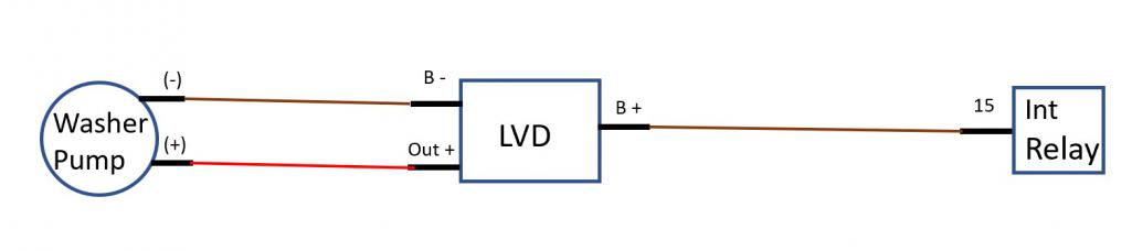
The circuit is so simple there is really no need for a diagram. See the pic in my first post of the 3-way connector? One of those wires in is the original brown/blk (S1) wire from the circuit that is supposed to go into the relay socket. One wire coming out now goes to the relay socket to complete the original circuit. The other wire coming out goes to the (+) on the washer pump. The washer pump is grounded to chassis through its mounting screw. That's it and the simplicity is why I want to make this work.
Quite simply, I need a switch on the wire between the 3-way and pump that is closed when there is 12v on that wire, and open the rest of the time. Digging around, it looks like I need a low voltage disconnect. Thinking something https://www.amazon.com/Undervoltage-Automatic-Charging-Protection-Controller/dp/B07RS49D6B might work. Wonder if anyone with more electronic smarts could confirm.
Now that I know leaving the washer pump connected isn't going to fry the intermittent circuit, I'm leaving it connected for now as I need the washer pump more than the intermittent. I'm optimistic this one-wire, no switch modification solution could work.

Posted by: Bartlett 914 Jul 30 2022, 01:08 PM
It has been awhile since I worked with the washer circuit. I do remember that the intermittent relay timing circuit gets fouled when installing a washer pump. It had to do with the resistance of the coil in the washer relay. The solution I did was to make a high impedance circuit that would then pull the relay for the washer pump.
Posted by: Superhawk996 Jul 30 2022, 01:18 PM
The circuit is so simple there is really no need for a diagram.
I'm not buying that. If it were that simple, it would be working as you thought it would and as Jeff speculated.

I looked at Jeff's write up, your posts etc. With all the piecemeal figures, and diagrams without labeling of how the circuits are wired, fed power, and ground, it just doesn't click for me. It's just the way I was trained by USAF. I need a schematic to understand the big picture and to rule out unintended ground paths. We'll call it a personal flaw.
Posted by: bbrock Jul 30 2022, 03:51 PM
The circuit is so simple there is really no need for a diagram.
I'm not buying that. If it were that simple, it would be working as you thought it would and as Jeff speculated.
I looked at Jeff's write up, your posts etc. With all the piecemeal figures, and diagrams without labeling of how the circuits are wired, fed power, and ground, it just doesn't click for me. It's just the way I was trained by USAF. I need a schematic to understand the big picture and to rule out unintended ground paths. We'll call it a personal flaw.
No, it's simple. You are trying to over complicate it
. Note that Jeff said "he was told" this would work and Sir Andy said you could take power from that wire for the washer, but did not go that route himself. I might be the first one stubborn enough to try it.However, they are both right... sort of. If you DON'T have intermittent wipers, you can just take power off the brown/black wire for the washer pump. Pull back on the lever and the pump will run, but you won't get the few cycles of wiper unless unless you have an intermittent harness and relay installed. If those ARE installed, you get a few cycles of wiper when the washer pump runs just like we want. But now there is a problem because that brown/black wire is supposed to be connected to ground in all wiper lever positions other than down ("J"). The ground defeats the intermittent circuit so it doesn't run when the lever is in "off," "low speed," or "high speed" position. Pulling down to J disconnects the brown/black from everything, making it a dead wire. That lets the intermittent run on low speed by energizing the 53. The problem being that hooking the brown/black wire to the pump creates a new path to ground so it doesn't become a dead wire when the lever is pulled down to "J" position. Thus, the intermittent circuit remains defeated.
Important to remember that the brown/black wire was never intended to run a washer pump by the factory. It just happens to be a handy source for 12v when the washer lever is pulled back on the stalk.
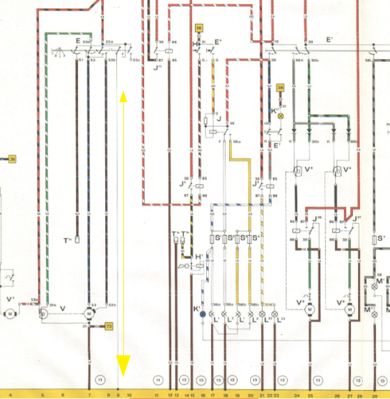
I've added the full circuit diagram below, but the only things not shown in the snippet above are what the various switch wires attach to. Those are:
S1 - attaches to 15 on intermittent relay (or taped up and dead end if that option isn't present).
53 - goes to low speed power input on wiper motor
53b - high speed power on wiper motor
53c - not present but apparently where the factory ran power for an electric washer pump on other models. I'm guessing on sixes too.
And if the intermittent option is installed, there is an additional harness that connects the relay to the wiper motor and brown/black wire which is shown in Jeff's article.
The bottom line is that connecting the brown/black wire to anything that creates a path to ground F's up the intermittent circuit as it was designed by the factory. That needs to be an open, dead end wire when the lever is pulled down into the "J"/intermittent position.
Posted by: bbrock Jul 31 2022, 10:16 AM
I went ahead and ordered one of these low voltage disconnect modules. There are DIY circuits available, but just to source parts would cost 3X as much and not be as compact.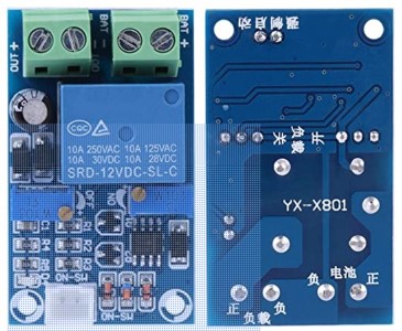
https://www.amazon.com/gp/product/B07RS49D6B/ref=ox_sc_act_title_1?smid=A30FF1YSS5LSJQ&psc=1
This will be installed between the washer pump and 3-way connector with wiring as follows:
B+ -> brwn/blk wire from 3-way
B- -> chassis ground at washer pump
Out + -> + on washer pump (I will change this wire to rd/blk to reflect it is now a switched power wire)
This SHOULD leave the relay contacts open when the wiper switch is pulled down into the "J" intermittent position and break the path from the brwn/blk wire to ground. When the lever is pulled back for washer, it should energized the circuit on the module which will sense voltage above the cut on threshold and close the relay contacts allowing 12v to flow to the pump.
It should be here later this week and I'll report how it works.
Posted by: Superhawk996 Jul 31 2022, 10:27 AM
I went ahead and ordered one of these low voltage disconnect modules.
More stuff for the "simple" schematic to reflect.

I still can't picture it.
 I stared (sideways ) at the column switch schematic you sent for a while and I'm still not convinced I understand how that column switch is wired and/or where the power is coming from to the intermittent relay when you put it in the J position.
 I am almost tempted to go find the box that has my manuals and schematics and dig them out. Like you, now that there is a mystery to be solved, I'd love to solve it. However, there is so much yet to be packed, I'm not going backward to dig out reference materials. I trust that you have a plan.

Posted by: windforfun Jul 31 2022, 10:32 AM
I went ahead and ordered one of these low voltage disconnect modules.
More stuff for the "simple" schematic to reflect.
I still can't picture it.
I stared (sideways ) at the column switch schematic you sent for a while and I'm still not convinced I understand how that column switch is wired and/or where the power is coming from to the intermittent relay when you put it in the J position. I am almost tempted to go find the box that has my manuals and schematics and dig them out. Like you, now that there is a mystery to be solved, I'd love to solve it. However, there is so much yet to be packed, I'm not going backward to dig out reference materials. I trust that you have a plan.
I know what you mean about deciphering these "schematics." They're "Greek to me" too & I have a MS degree in EE. They're more like block diagrams with unique notation.
Posted by: bbrock Jul 31 2022, 11:29 AM
I went ahead and ordered one of these low voltage disconnect modules.
More stuff for the "simple" schematic to reflect.
I still can't picture it.
I stared (sideways ) at the column switch schematic you sent for a while and I'm still not convinced I understand how that column switch is wired and/or where the power is coming from to the intermittent relay when you put it in the J position. I am almost tempted to go find the box that has my manuals and schematics and dig them out. Like you, now that there is a mystery to be solved, I'd love to solve it. However, there is so much yet to be packed, I'm not going backward to dig out reference materials. I trust that you have a plan.
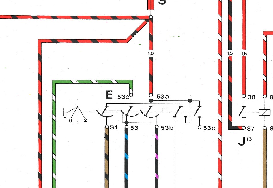
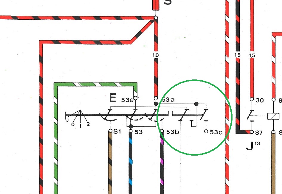
Power for the intermittent comes from 53 (low speed input to motor). If you mentally move the contact diagrams above 53 and directly bellow 53a through the various positions, you can see 53 is connected to 53a (from the starter switch) on the left contact in switch positions J & 0, and is connected through that left contact in position 1, then disconnected in position 2. Why it is connected to power in position 0 is a bit of a mystery to me, as is what 53e is doing. I'm not even sure what it is connected to at 31b.
Isolating the problem by just looking at the part of the circuit modified by adding the washer pump, the pump works fine when connected to S1 (brwn/blk) but the intermittent function does not. Disconnect the pump to break the pathway to ground and the intermittent function works again. Simply, the S1 wire needs to connect to the washer pump when voltage is applied, and be disconnected when it is not.
Here, I added the "complicated" part for you.
Posted by: Superhawk996 Jul 31 2022, 11:43 AM
Here, I added the "complicated" part for you.
You dick
 and I use that as your usual badge of honor.
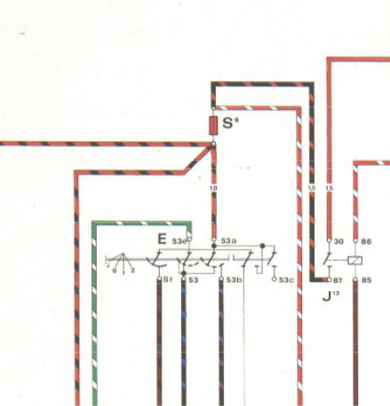
Your comment: "Power for the intermittent comes from 53 (low speed input to motor). If you mentally move the contact diagrams above 53 and directly bellow 53a through the various positions, you can see 53 is connected to 53a (from the starter switch) on the left contact in switch positions J & 0, and is connected through that left contact in position 1, then disconnected in position 2. Why it is connected to power in position 0 is a bit of a mystery to me, as is what 53e is doing. I'm not even sure what it is connected to at 31b. "
That green and white wire isn't always power. When the wipers are turned off, it is connected to ground and acts as an inertia brake by putting ground to the armature. it's actual condition (power or ground) depends on the position of the rotary switch that is connected to the wiper motor shaft.
As for position J -- the only thing that is ever connected when in position J, is the green and white (53e) to 53. (per comment below - Green/White is the inertia brake)
In low speed, the actual 12V power feed is coming through 53a to the set of contacts that also feed 53b when in the 2nd position. Note in the 1st position 53a feeds feeds 53. In the second position (high) then it feeds 53b.
What is on the green and white wire (power or ground) is dependent on the position of the 3 track rotary switch that is attached to the motor armature.
When the motor is parked, I think the green and white will actually have ground on it . . . but I'm not 100% sure and would want to measure this. When the switch is moved to position #1, that ground is interrupted and the 12v power comes over from that other set of contacts fed from 53a to 53.
This is why I need the schematic of where (and how - by pin#) your intermittent relay and washer were installed relative to this circuit. It really isn't a simple circuit.
I could be wrong, but I think the green and white wire (i.e. the inertia brake) is what grounding your intermittent wiper relay? Obviously I'm not 100% sure.
Posted by: Superhawk996 Jul 31 2022, 12:50 PM
@http://www.914world.com/bbs2/index.php?showuser=20845
Do you actually have your intermittent relay wired in just like this?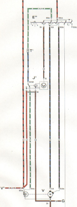
I think that you are saying no. It sounds to me like you are using the motor low speed feed as your control (S terminal) to the intermittent relay rather than the brown/black wire that is only getting 12V when stalk is pulled?
Your "schematic" you provided seems to imply that you're using pin 15 as the output from your intermittent relay and that is what is feeding the washer pump? That would not be the same intermittent wiring as the 914/6 & Bowlsby kit.
And if I understand your intent correctly, you want:
1) Washer pump operates along with intermittent wipe when you pull the switch?
2) Intermittent wipe operates continuously when the switch is in position J?
Posted by: bbrock Jul 31 2022, 01:42 PM
@http://www.914world.com/bbs2/index.php?showuser=20845
Do you actually have your intermittent relay wired in just like this?
I think that you are saying no. It sounds to me like you are using the motor low speed feed as your control (S terminal) to the intermittent relay rather than the brown/black wire that is only getting 12V when stalk is pulled?
Your "schematic" you provided seems to imply that you're using pin 15 as the output from your intermittent relay and that is what is feeding the washer pump? That would not be the same intermittent wiring as the 914/6 & Bowlsby kit.
Whoops! My bad. I labeled that relay terminal from memory and was too lazy to look up whether it was correct. I do have my relay wired exactly as Jeff outlines in his article. So my complex diagram should have that labeled as 'S.' Sorry about that. To be clear, the brwn/blk wire is the control wire for the intermittent.
You're explanation of the grn/wht wire makes sense and I think completes the understanding for me. The brwn/blk wire goes to ground in all positions except "J" and when the lever is pulled back. This circuit flow style schematic makes it impossible to tell the exact wire path of that ground. I think it is through the grn/wht wire. The relay schematic might shed some light on that but I'm too lazy right now.
All I need to know is that the brwn/blk wire sometimes works as a ground, sometimes as V+, and sometimes as nothing at all. I suppose that is German ingenuity to use a single wire for multiple purposes but it sure is confusing.
And if I understand your intent correctly, you want:
1) Washer pump operates along with intermittent wipe when you pull the switch?
2) Intermittent wipe operates continuously when the switch is in position J?
Right, and right now splitting off the brwn/blk wire to the washer (+), then #1 works. If you disconnect that wire from the washer pump which restores the stock wiring config, #2 works.
Posted by: Superhawk996 Jul 31 2022, 01:46 PM
Instead of the kit, I'm branching off the brown/black wire that feeds power to the intermittent relay for cars that have them. 12v is fed to that wire whenever the wiper lever is pulled back for manual pulse wipers, or down into the intermittent position.
As I review previous posts to understand what intent was I think this is a faulty assumption. Again you have parts and I'm looking at schematics so I'll trust what you measure.
From the schematic -- When that stalk is pulled down, I think you're only connecting 53e (green & white inertia brake) to the low speed motor feed 53.
Posted by: Superhawk996 Jul 31 2022, 01:48 PM
just saw your other post
Yes - the schematics are a bit ambiguous where lines are crossing.
My understanding of how Porsche does them is that if lines cross and there is no dot (usually a solid dot) there is no connection.
At wire ends there is often a empty (hollow) dot indicating a connection point.
Posted by: bbrock Jul 31 2022, 01:51 PM
Instead of the kit, I'm branching off the brown/black wire that feeds power to the intermittent relay for cars that have them. 12v is fed to that wire whenever the wiper lever is pulled back for manual pulse wipers, or down into the intermittent position.
As I review previous posts to understand what intent was I think this is a faulty assumption. Again you have parts and I'm looking at schematics so I'll trust what you measure.
From the schematic -- When that stalk is pulled down, I think you're only connecting 53e (green & white inertia brake) to the low speed motor feed 53.
That post was very early as I was still figuring out how this worked. I corrected it later on. 12v is sent on brwn/blk ONLY when the lever is pulled back, it is disconnected from the circuit when pulled down, and grounded in all other positions.
Posted by: Superhawk996 Jul 31 2022, 01:58 PM
You're explanation of the grn/wht wire makes sense and I think completes the understanding for me. The brwn/blk wire goes to ground in all positions except "J" and when the lever is pulled back. This circuit flow style schematic makes it impossible to tell the exact wire path of that ground. I think it is through the grn/wht wire. The relay schematic might shed some light on that but I'm too lazy right now.
No -- that brown / black doesn't get ground though the green/white.
Here is where the brown/black gets ground -- it's coming though the NC (normally closed) connection of the pull switch. When the switch is pulled this ground (yellow arrows) is interrupted and 12v is applied as sourced from 53a.
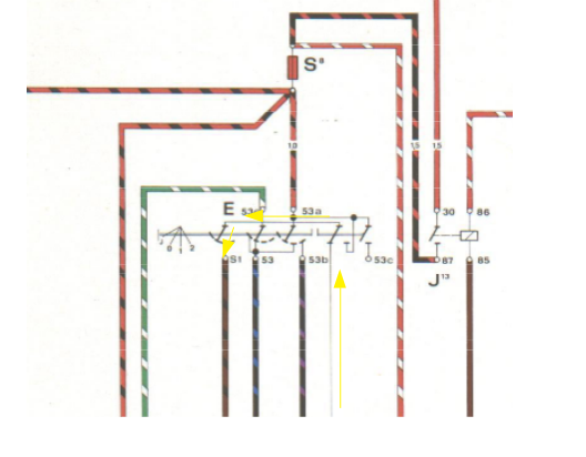
See post 29 again. Where lines cross without a dot (solid or hollow) there is no connection.
As stated by @http://www.914world.com/bbs2/index.php?showuser=8476 - - - some of the switch notation is seriously confusing and/or lacking in clarity even to those of us that use schematics heavily.
I'll stand corrected if you measure something different. When ever I do this on my car, I do as much "verification" as I can with a DMM that the switch is operating the way I see it on the schematic. I'm not always right.
Here is the full current waterfall for that ground circuit. Because it's a solid line and doesn't have a color code or wire gauge, I assume that means that column pull switch is actually sourced from a chassis ground between the steering column and the body.
Posted by: bbrock Jul 31 2022, 01:59 PM
just saw your other post
Yes - the schematics are a bit ambiguous where lines are crossing.
My understanding of how Porsche does them is that if lines cross and there is no dot (usually a solid dot) there is no connection.
At wire ends there is often a empty (hollow) dot indicating a connection point.
You are right. I've been reading it wrong and it makes even more sense now but doesn't change the diagnosis. Reading it correctly, 53 only gets 12v when in position "1" which is low speed. That makes perfect sense now.
I still say that the only wire we really need to be worried about is brwn/blk which is the only one modded by adding the pump, but it's fun to know how the complete circuit works.
Posted by: bbrock Jul 31 2022, 02:07 PM
You're explanation of the grn/wht wire makes sense and I think completes the understanding for me. The brwn/blk wire goes to ground in all positions except "J" and when the lever is pulled back. This circuit flow style schematic makes it impossible to tell the exact wire path of that ground. I think it is through the grn/wht wire. The relay schematic might shed some light on that but I'm too lazy right now.
No -- that brown / black doesn't get ground though the green/white.
Here is where the brown/black gets ground -- it's coming though the NC (normally closed) connection of the pull switch. When the switch is pulled this ground (yellow arrows) is interrupted and 12v is applied as sourced from 53a.
See post 29 again. Where lines cross without a dot (solid or hollow) there is no connection.
As stated by @http://www.914world.com/bbs2/index.php?showuser=8476 - - - some of the switch notation is seriously confusing and/or lacking in clarity even to those of us that use schematics heavily.
I'll stand corrected if you measure something different. When ever I do this on my car, I do as much "verification" as I can with a DMM that the switch is operating the way I see it on the schematic. I'm not always right.
And the intermittent is also getting power from 53a via the relay harness between the relay and wiper motor.
Posted by: bbrock Jul 31 2022, 02:09 PM
And I agree about the confusion. I'm not a fan of these circuit flow style schematics. I can see why they did it, but the older schematics are easier to read for me. Not to say they aren't sometimes clear as mud though.
Posted by: Superhawk996 Jul 31 2022, 02:26 PM
I don't think you'll be able to get the condition where Position J operates the intermittent continuously.
Am I mistaken?
Posted by: bbrock Jul 31 2022, 02:26 PM
No -- that brown / black doesn't get ground though the green/white.
Here is where the brown/black gets ground -- it's coming though the NC (normally closed) connection of the pull switch. When the switch is pulled this ground (yellow arrows) is interrupted and 12v is applied as sourced from 53a.
What I meant about not being able to tell the pathway where that push switch is being grounded. That thin black line where your arrow is pointing up is doesn't say much to me other than it is grounded. Maybe through the little copper tab that gets lost on the switch cluster? I don't remember what stops working when that goes missing. I was thinking it was the horn but maybe more grounds through there.
Anyway, the DMM says this. Pull back the lever and you get 12v out of brwn/blk. Pull down on the lever and you get 0v and infinite Ohms to ground. That's really all I needed to figure out how to make the washer pump work the way I want and confirmed by testing with the wire connected and disconnected to the pump. Pretty simple.
All the rest is just satisfying curiosity.
Posted by: bbrock Jul 31 2022, 02:31 PM
I don't think you'll be able to get the condition where Position J operates the intermittent continuously
Am I mistaken?
You are mistaken which I have demonstrated by doing it manually. All I have to do is disconnect the brown/black wire from the washer pump and the continuous intermittent function is restored. The LVD module I order should simply automate that process by connecting brown/black to the pump only when 12v is present on the wire, and disconnecting when it is not.
Posted by: lesorubcheek Jul 31 2022, 02:54 PM
Anyway, the DMM says this. Pull back the lever and you get 12v out of brwn/blk. Pull down on the lever and you get 0v and infinite Ohms to ground. That's really all I needed to figure out how to make the washer pump work the way I want and confirmed by testing with the wire connected and disconnected to the pump. Pretty simple.
All the rest is just satisfying curiosity.
This makes sense, I think. It's obviously a fact since you see it on the meter. So please see if this is correct.
1. When the wiper stalk is in positions 0, 1 or 2, the intermittent relay can receive +12V when the stalk is pulled back as has been explained previously via the black/brown wire connecting S1 of the switch to S of the relay.
2. When the stalk is in positions 0, 1 or 2,and the lever is not pulled back, the intermittent relay is receiving a ground at S via the black/brown wire.
3. When the stalk is in the J position, the relay at S is seeing an open circuit.
For the longest time item 3 is what wouldn't sink in, but finally I see where the relay has a +12v input on connector 15. Just kept thinking the relay must get a +12v input on S in order to work, but it appears the real power for the relay is through connector 15 and S is just a 3 state input, either ground +12v or open circuit. The logic then I guess would be that when S is ground, the relay remains off, if a +12v is seen, it activates for once or twice, then shuts off and when open circuit is at S, it activates using whatever time interval it's set up to cycle. I sure hope this is correct because I'm running out of Tylenol.
Dan
Posted by: Superhawk996 Jul 31 2022, 02:58 PM

Ok now I think I understand your idea better. I'm used to thinking input is on the left side.
So this is what you meant? 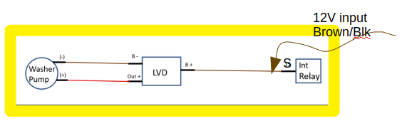
So when you pull the stalk, you trigger the intermittent 12v input (S) to the relay.
Simultaneously the the wiper pump is on as long as 12v is present. Then when the black/brown returns to ground the pump stops, the wiper pump is decoupled, and the intermittent stays active.
Will be interesting to see if it indeed works.
But by the time you have to put that little gizmo in there I'm thinking we're back to an Arduino (in effect) 
But if it works as you propose . . . . we'll all owe you a beer
Posted by: bbrock Jul 31 2022, 03:47 PM
Ok now I think I understand your idea better. I'm used to thinking input is on the left side.
So this is what you meant?
So when you pull the stalk, you trigger the intermittent 12v input (S) to the relay.
Simultaneously the the wiper pump is on as long as 12v is present. Then when the black/brown returns to ground the pump stops, the wiper pump is decoupled, and the intermittent stays active.
Will be interesting to if it indeed works.
But by the time you have to put that little gizmo in there I'm thinking we're back to an Arduino (in effect)
But if it works as you propose . . . . we'll all owe you a beer
Correct. It's all about opening and closing the relay that connects B+ to Out+ depending on what brwn/blk is doing on the B+ side. Where I could get screwed is if the sensor circuit of B+/B- allows current to flow to ground even when the relay is open. It shouldn't because the intended use case of the LVD is to disconnect a battery from its load if the voltage drops below a set threshold but we shall see.
Well, it is much simpler than an arduino on my end because I don't have to design and build the circuit around the arduino. I also don't think an arduino would work well here. If the arduino were powered by the brwn/blk wire, it would have to boot and load the sketch every time the washer lever was pulled. That would cause a significant delay. The alternative would be to power the arduino independently which is more wire, a more complicated circuit, and another potential failure point.
If this works, it is close to the original one-wire idea. I do have to add a short ground wire from B- to ground to read "battery" voltage, but you sort of have to do that to ground the pump anyway. I'll do that with a "Y" wire with a ring connector to attach to chassis ground at the pump mount, another with spade to plug into pump (-), and a bare end to clamp into the B- terminal on the LVD. Should still be very compact and tidy. Just please don't leak to ground!


Posted by: Superhawk996 Jul 31 2022, 04:10 PM
Now that I've had some time to think about the LVD solution here are some thoughts.
I think the same overall goal of disconnecting the pump ground path from the intermittent relay could be achieved with a simple MOSFET transistor. The control input to the MOSFET gate would be the 12v input from Black/Brown stalk switch,
I can't tell from the specs for the proposed LDV if it can handle inductive loads or is just for resistive load like a light, LED, or battery.
Inductive loads (relays, motors) can generate voltage spikes that will damage electronic components when they are shut off abruptly. If a MOSFET were being used to switch the washer pump, I'd say that you would want to put a flyback diode in the circuit to protect the circuit.
Can't tell if the LVD proposed has internal flyback diodes. Maybe, maybe not depending on whether they designed it to handle inductive loads. You could easily add your own externally.
For $8 - can't go wrong even it it eventually dies from an inductive load. At that point you could switch to a MOSFET switch like this for around the same cost and is even smaller:
https://www.amazon.com/ANMBEST-High-Power-Adjustment-Electronic-Brightness/dp/B09KGDDS37/ref=sr_1_1_sspa?crid=38YTDLFDBPEVY&keywords=mosfet%2Bswitch&qid=1659305245&s=industrial&sprefix=mosfet%2Bswith%2Cindustrial%2C126&sr=1-1-spons&th=1
Posted by: Spoke Jul 31 2022, 04:44 PM
I've been following this discussion but haven't chimed in because I'm severely confused on the operation.
I'm trying to understand this switch function. Please let me know if I've got this correct.
Switch positions:
J : Stalk pulled back; Relates to left-most selection of the contacts.
0 : Wipers off
1 : Wipers on low speed
2 : Wipers on high speed.
Contact S1:
J : No connection
0 : Ground
1 : Ground
2 : 12V
Did I get this right?
Posted by: bbrock Jul 31 2022, 04:57 PM
Now that I've had some time to think about the LVD solution here are some thoughts.
I think the same overall goal of disconnecting the pump ground path from the intermittent relay could be achieved with a simple MOSFET transistor. The control input to the MOSFET gate would be the 12v input from Black/Brown stalk switch,
I can't tell from the specs for the proposed LDV if it can handle inductive loads or is just for resistive load like a light, LED, or battery.
Inductive loads (relays, motors) can generate voltage spikes that will damage electronic components when they are shut off abruptly. If a MOSFET were being used to switch the washer pump, I'd say that you would want to put a flyback diode in the circuit to protect the circuit.
Can't tell if the LVD proposed has internal flyback diodes. Maybe, maybe not depending on whether they designed it to handle inductive loads. You could easily add your own externally.
For $8 - can't go wrong even it it eventually dies from an inductive load. At that point you could switch to a MOSFET switch like this for around the same cost and is even smaller:
https://www.amazon.com/ANMBEST-High-Power-Adjustment-Electronic-Brightness/dp/B09KGDDS37/ref=sr_1_1_sspa?crid=38YTDLFDBPEVY&keywords=mosfet%2Bswitch&qid=1659305245&s=industrial&sprefix=mosfet%2Bswith%2Cindustrial%2C126&sr=1-1-spons&th=1
Don't think that one will work. It switches gnd but not vcc. I need the other way round. There is a question and couple reviews about it.
I looked at mosfet circuits but the potential for a plug-n-play solution for <$8 seemed a no brainer. I found a couple DIY circuits that look very similar to this module when built. They both used flyback diodes. Hoping this does the same. I think I spy at least 3 diodes in the pics on Amazon. Can't say for sure.
Posted by: bbrock Jul 31 2022, 05:09 PM
I've been following this discussion but haven't chimed in because I'm severely confused on the operation.
I'm trying to understand this switch function. Please let me know if I've got this correct.
Switch positions:
J : Stalk pulled back; Relates to left-most selection of the contacts.
0 : Wipers off
1 : Wipers on low speed
2 : Wipers on high speed.
Contact S1:
J : No connection
0 : Ground
1 : Ground
2 : 12V
Did I get this right?
Ah! There is something I should have explained early that will not be obvious unless you have messed with the intermittent option. J is lever pulled down and is not available by default. There is a plastic tab in the switch that has to be broken off to allow the lever to move one click down from the off position. So to complete what you have:
Switch positions:
J : Stalk pulled down - intermittent; Relates to left-most selection of the contacts.
0 : Wipers off
1 : Wipers on low speed
2 : Wipers on high speed.
P: Stalk pulled back - activate short cycle of wipers.
Contact S1:
J : No connection
0 : Ground
1 : Ground
2 : Ground
P : 12v
Posted by: Superhawk996 Jul 31 2022, 05:17 PM
Don't think that one will work. It switches gnd but not vcc. I need the other way round. There is a question and couple reviews about it.
Not a big deal to have the MOSFET switching Ground. The resistance between the gate (the control) and either the source or drain is so high that the intermittent relay that will be sharing the gate connection will never "see" the ground through the gate - source junction.
Posted by: Spoke Jul 31 2022, 06:10 PM
Ah! There is something I should have explained early that will not be obvious unless you have messed with the intermittent option. J is lever pulled down and is not available by default. There is a plastic tab in the switch that has to be broken off to allow the lever to move one click down from the off position. So to complete what you have:
Switch positions:
J : Stalk pulled down - intermittent; Relates to left-most selection of the contacts.
0 : Wipers off
1 : Wipers on low speed
2 : Wipers on high speed.
P: Stalk pulled back - activate short cycle of wipers.
Contact S1:
J : No connection
0 : Ground
1 : Ground
2 : Ground
P : 12v
@http://www.914world.com/bbs2/index.php?showuser=20845
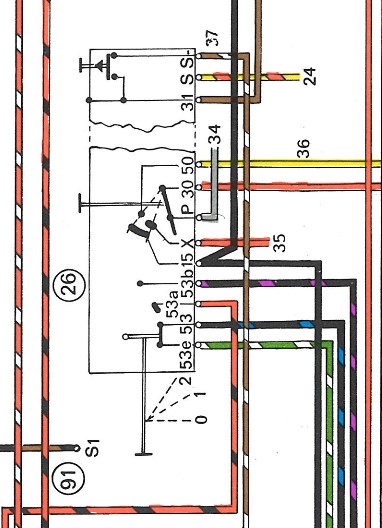
OK, so for position P stalk pulled back, does that move these 2 contacts? I wonder if the double horizontal lines broken between the 2 contacts means when the stalk is pulled back.
If so, it looks like you want to connect the washer motor to 53c which looks like it is not wired out. 53c is open unless the stalk is pulled back.
So you had the washer motor connected to S1, correct? Pull back on the stalk and the washer and wipers go. But since the motor is connected from S1 to ground, the motor shows S1 a ground connection thus the J, 0, 1, 2 position of S1 are all ground and the intermittent wipers do not work. Does this sound plausible?
Attached image(s)
Posted by: Spoke Jul 31 2022, 06:31 PM
Now that I've had some time to think about the LVD solution here are some thoughts.
I think the same overall goal of disconnecting the pump ground path from the intermittent relay could be achieved with a simple MOSFET transistor. The control input to the MOSFET gate would be the 12v input from Black/Brown stalk switch,
I can't tell from the specs for the proposed LDV if it can handle inductive loads or is just for resistive load like a light, LED, or battery.
Inductive loads (relays, motors) can generate voltage spikes that will damage electronic components when they are shut off abruptly. If a MOSFET were being used to switch the washer pump, I'd say that you would want to put a flyback diode in the circuit to protect the circuit.
Can't tell if the LVD proposed has internal flyback diodes. Maybe, maybe not depending on whether they designed it to handle inductive loads. You could easily add your own externally.
For $8 - can't go wrong even it it eventually dies from an inductive load. At that point you could switch to a MOSFET switch like this for around the same cost and is even smaller:
https://www.amazon.com/ANMBEST-High-Power-Adjustment-Electronic-Brightness/dp/B09KGDDS37/ref=sr_1_1_sspa?crid=38YTDLFDBPEVY&keywords=mosfet%2Bswitch&qid=1659305245&s=industrial&sprefix=mosfet%2Bswith%2Cindustrial%2C126&sr=1-1-spons&th=1
Don't think that one will work. It switches gnd but not vcc. I need the other way round. There is a question and couple reviews about it.
I looked at mosfet circuits but the potential for a plug-n-play solution for <$8 seemed a no brainer. I found a couple DIY circuits that look very similar to this module when built. They both used flyback diodes. Hoping this does the same. I think I spy at least 3 diodes in the pics on Amazon. Can't say for sure.
@http://www.914world.com/bbs2/index.php?showuser=20845
I think I agree with you about the switching. The intermittent relay only functions in the J position when S1 is open. Thus grounding pin S on the relay will disable it. This is why tapping the washer motor on S1 to ground disabled the relay.
Therefore it can be assumed that the input pin S on the relay has an internal pull-up circuit to activate it when the net connected to pin S is open circuited and pin S voltage will float upwards to some positive voltage. Is this the voltage you measured or was going to measure?
If pin S does float upwards then putting a FET input on pin S will likely turn on the washer when the intermittent relay is active (in J position).
Posted by: bbrock Jul 31 2022, 06:45 PM
@http://www.914world.com/bbs2/index.php?showuser=20845
OK, so for position P stalk pulled back, does that move these 2 contacts? I wonder if the double horizontal lines broken between the 2 contacts means when the stalk is pulled back.
If so, it looks like you want to connect the washer motor to 53c which looks like it is not wired out. 53c is open unless the stalk is pulled back.
So you had the washer motor connected to S1, correct? Pull back on the stalk and the washer and wipers go. But since the motor is connected from S1 to ground, the motor shows S1 a ground connection thus the J, 0, 1, 2 position of S1 are all ground and the intermittent wipers do not work. Does this sound plausible?
Yes on all counts.
I think 53c is indeed the correct (and factory according to @lesorubcheeks ) way to connect the washer. It would require adding a wire, and possibly a pin to the switch connector to run through the bulkhead and over to the washer pump. I don't know about you all, but working on anything in the steering column is a recipe for a bad mood for me. Much of that is because the connectors for my signal and wiper switches fit really tight so I have to pull the knee pad to get sufficient access to unplug them. Plus, I don't like running stray wires through the car. Had I thought of this when I was rebuilding the harness, I might have added a 53c wire.
Sir Andy and Jeff Bowlsby drew my attention to the S1 wire being powered in the P position on the lever, and now I'm like a dog with a bone. If this works, the conversion bits will cost < $50 which includes pump, LVD and enclosure, connectors, and wire, and I'll retain my intermittent function. The best part is the whole retrofit takes place up front except to pull the rubber washer hoses off the plunger valve on the switch. That can be done from under the dash without taking anything apart.
Up front, you have to remove the washer bottle, fuel tank filler neck, and charcoal canister to gain access to everything. Much easier IMO, than working on the column.
For cars not running intermittent wipers, it's looking like replacing the wiper plunger valve with a microswitch was never necessary for cars that have the S1 wire in them. For those, you can just dig the end of the wire out of the harness per Jeff's instructions, and extend it to plug into the washer pump and be done with it!
Posted by: bbrock Jul 31 2022, 06:56 PM
I think I agree with you about the switching. The intermittent relay only functions in the J position when S1 is open. Thus grounding pin S on the relay will disable it. This is why tapping the washer motor on S1 to ground disabled the relay.
Therefore it can be assumed that the input pin S on the relay has an internal pull-up circuit to activate it when the net connected to pin S is open circuited and pin S voltage will float upwards to some positive voltage. Is this the voltage you measured or was going to measure?
Yes, but the voltage readings are small. In the J position with the washer disconnected, I read ~4-11mV which cycles repeatedly. I didn't time the cycles but they seemed like they might be about what the wiper intervals are. Does that sound right?
This sounds interesting except I don't want the washer to run in the J position. Washer should run only in P position and only the intermittent relay should run in J position.
I shouldn't have called this a "simple" circuit before. I should have called it a German circuit. Simple in design but complex in function.
Posted by: Spoke Jul 31 2022, 07:39 PM
Yes, but the voltage readings are small. In the J position with the washer disconnected, I read ~4-11mV which cycles repeatedly. I didn't time the cycles but they seemed like they might be about what the wiper intervals are. Does that sound right?
I would think there would be more voltage deflection than a couple of millivolts. Assuming you had it on DC mode. I wonder what the AC mode would read. If this were a voltage ramp you might get different reading on AC mode.
This is good though because the FET circuit may not have enough resistance to ground to inhibit the intermittent relay and there's not enough voltage to turn the FET on.
Posted by: bbrock Jul 31 2022, 08:42 PM
Yes, but the voltage readings are small. In the J position with the washer disconnected, I read ~4-11mV which cycles repeatedly. I didn't time the cycles but they seemed like they might be about what the wiper intervals are. Does that sound right?
I would think there would be more voltage deflection than a couple of millivolts. Assuming you had it on DC mode. I wonder what the AC mode would read. If this were a voltage ramp you might get different reading on AC mode.
This is good though because the FET circuit may not have enough resistance to ground to inhibit the intermittent relay and there's not enough voltage to turn the FET on.
Yeah, I just wrote those readings off as noise. I didn't think to measure AC. the relay is kind of a pain to get to with the charcoal canister in place, but next time I'm in there, I'll see if I can get some AC readings.
Posted by: Superhawk996 Aug 1 2022, 06:38 AM
I shouldn't have called this a "simple" circuit before. I should have called it a German circuit. Simple in design but complex in function.
Well said.

That is why I love schematics. I've messed with that stalk switch about 20 years ago but no way to recall all that from memory. The 3 track rotary switch on the motor armature and the inertia brake function further complicate things. Schematics . . . Schematics . . . Schematics. Must have for troubleshooting.
FYI - I was able to locate all those schematics on the interwebz so I didn't end up having to pull my reference materials out of packing boxes. You're still a dick for making me find the schematics to help you . . .
But then again, I do owe you for letting me drive your car! Please do put up a proper "How To" write up once you get this whole thing sorted. It really should get pinned over in the classics section.
Posted by: Superhawk996 Aug 1 2022, 06:53 AM
Here's the blurb from the 73' owner's manual on how intermittent works with the factory graphic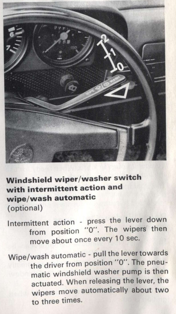
Posted by: bbrock Aug 1 2022, 08:39 AM
I shouldn't have called this a "simple" circuit before. I should have called it a German circuit. Simple in design but complex in function.
Well said.
That is why I love schematics. I've messed with that stalk switch about 20 years ago but no way to recall all that from memory. The 3 track rotary switch on the motor armature and the inertia brake function further complicate things. Schematics . . . Schematics . . . Schematics. Must have for troubleshooting.
FYI - I was able to locate all those schematics on the interwebz so I didn't end up having to pull my reference materials out of packing boxes. You're still a dick for making me find the schematics to help you . . .
But then again, I do owe you for letting me drive your car! Please do put up a proper "How To" write up once you get this whole thing sorted. It really should get pinned over in the classics section.
Didn't I post the full schematic of the circuit at the bottom of page 1?
I do appreciate the help. It's good to have multiple eyes thinking through the problem. I may revisit a simple MOSFET circuit. I think it might be possible with just the FET, a couple resistors and a diode which would be simpler and fully solid state compared with the LVD module. Will start with LVD and go from there.I still say we didn't need the full schematic to troubleshoot this problem though. We only needed to know how the S1 wire is supposed to behave because that is the only wire modified by connecting the pump. The switch diagram tells the whole story on that: Open in position "J", 12v, in Position "0", and grounded in all others. That provides enough info to work on solutions. The rest was was fun and interesting, and I learned a lot more about how to read these circuit flow style schematics, but not mission critical. Interesting through that the old style schematics don't provide nearly enough detail to even figure out that one wire. Doesn't even include the intermittent wire or position.
Thinking about bench testing the LVD module when it arrives. I think the critical tests will be that resistance between B+ and B-, and between B+ and Out+ need to be open with 0v on the brwn/blk wire. Resistance between B+ and Out+ should be near 0 ohms above ~10v on brwn/blk, and the resistance needs to drop without significant lag when the voltage is applied. Anything else I should be looking for?
Posted by: Superhawk996 Aug 1 2022, 09:03 AM
I still say we didn't need the full schematic to troubleshoot this problem though.
I did . . . just because that is the way I'm wired (pun intended) and was trained.
Probably the biggest piece for me was understanding how you had the intermittent relay wired in. For me, I need to see the big picture 1st before I can understand the details of what you had done. Words aren't good at conveying electrical circuit information. That is why schematics were invented.
I'm just hoping that you come up with a nice solution that allows operation of both the electric washer pump AND intermittent wipers since that is where I want to end up.
Posted by: lesorubcheek Aug 1 2022, 12:03 PM
If the goal is to have an open circuit at S on the intermittent relay, a very simple solution may also be just adding a diode inline. I tested a 5 amp diode in a simple circuit with a 12v bulb and the meter shows 1.3 M ohms to ground on the side that feeds the 12V, which is where the tap is presently the relay. It's not an open circuit, but may be high enough for the intermittent function to work in the J position. It'd be a quick and easy test. Just a thought.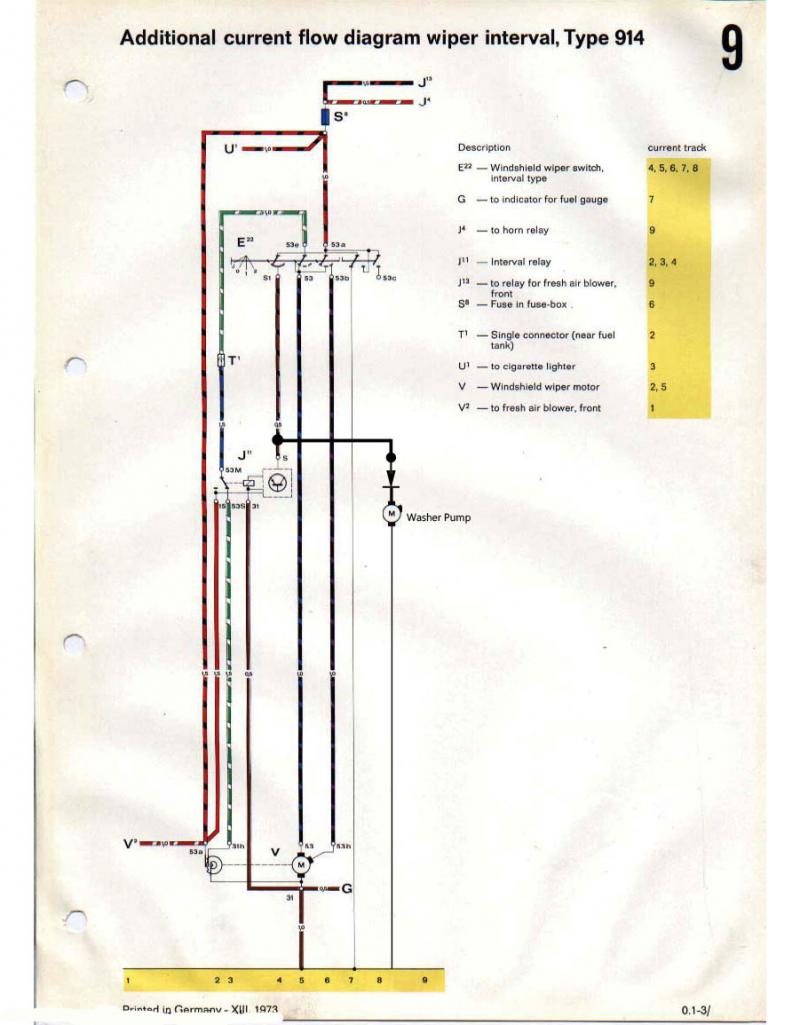
Dan
Posted by: bbrock Aug 1 2022, 01:40 PM
I did . . . just because that is the way I'm wired (pun intended) and was trained.
Yeah, I think it's a difference between engineering and ecology. The global ecosystem wasn't built by people so there is not blueprint or schematic of how it works. The scale and seemingly infinite variables is beyond human comprehension. The global circulation model is the most complex computer model ever developed, and only explains a tiny piece of our biosphere. We are good at homing in on just the subsystems that could be affected by the thing we are trying to understand.
To be fair, a good solution already exists. The full Car Magic conversion kits is something like $70 and provides everything needed to have electric washers and intermittent working as the factory intended. It just requires more aggressive modifications, labor, and $ than what I hope to accomplish here. The Car Magic kit is sitting on my coffee table just in case...
Posted by: Spoke Aug 1 2022, 05:08 PM
If the goal is to have an open circuit at S on the intermittent relay, a very simple solution may also be just adding a diode inline. I tested a 5 amp diode in a simple circuit with a 12v bulb and the meter shows 1.3 M ohms to ground on the side that feeds the 12V, which is where the tap is presently the relay. It's not an open circuit, but may be high enough for the intermittent function to work in the J position. It'd be a quick and easy test. Just a thought.
Dan

If indeed there is little voltage on this net when the intermittent relay is active then the diode or two would be a simple solution.
Posted by: bbrock Aug 1 2022, 06:18 PM
If the goal is to have an open circuit at S on the intermittent relay, a very simple solution may also be just adding a diode inline. I tested a 5 amp diode in a simple circuit with a 12v bulb and the meter shows 1.3 M ohms to ground on the side that feeds the 12V, which is where the tap is presently the relay. It's not an open circuit, but may be high enough for the intermittent function to work in the J position. It'd be a quick and easy test. Just a thought.
Dan
It indeed there is little voltage on this net when the intermittent relay is active then the diode or two would be a simple solution.
You have me curious. Did a little reading to learn about forward voltage. Sounds promising. I should have an assortment of diodes in the bin. Any recommendations on what to try?
Posted by: lesorubcheek Aug 1 2022, 06:34 PM
If the goal is to have an open circuit at S on the intermittent relay, a very simple solution may also be just adding a diode inline. I tested a 5 amp diode in a simple circuit with a 12v bulb and the meter shows 1.3 M ohms to ground on the side that feeds the 12V, which is where the tap is presently the relay. It's not an open circuit, but may be high enough for the intermittent function to work in the J position. It'd be a quick and easy test. Just a thought.
Dan
It indeed there is little voltage on this net when the intermittent relay is active then the diode or two would be a simple solution.
You have me curious. Did a little reading to learn about forward voltage. Sounds promising. I should have an assortment of diodes in the bin. Any recommendations on what to try?
We recently used some 20A 50V Schottkys for isolating the turn signals flashing when using the remote key lock. Gross overkill, but they were $1.50 each, so why not add some insurance. Any idea how many amps the washer pump motor draws? As long as you have headroom for amps and the voltage, should be good to try.
Dan
Posted by: bbrock Aug 1 2022, 06:55 PM
GENIUS!
Dug through my spares and found an unopened package of 1N4001 power diodes. Good for 50v and [EDIT: misread the data sheet. Only rated for 1 amp so I need to source a beefier diode, but the proof of concept is valid]30amps so plenty of head room. Vf is pretty high at 1.1v which is good for this application. Hooked one in series on the brwn/black wire and fired up the washer pump. Ran perfect. Pulled the lever down to turn on the intermittents and waited. No movement but a groan was heard from the motor, stopped, and repeated again after about 10 seconds. Hmm, sounded horrible but sounded like progress. I hooked up a second diode in series and WALLA! All functions are GO!
Should I add a third diode for an extra margin of isolation? So stoked! So the conversion now is down to:
- ~ $20 for a washer pump.
- A couple feet of wire
- 2-3 diodes
- (1) 3-way connector
- (1) 1/4" female spade crimp connector with locking tab
- (2) 1/4" female spade crimp connectors
- (1) ring connector (forgot the size I used)
Maybe $25 all in?
@http://www.914world.com/bbs2/index.php?showuser=25463 in my short remedial reading on diodes, I read that Schottky diodes have exceptionally low forward voltage so probably not the best choice. It seems cheap power diodes with high forward voltage are a better option.
Thank you, thank you for suggesting this. So simple and elegant. I'll use the LVD I ordered on my snow plow so it will go to good use. That was part of the calculation in ordering it.
Posted by: Spoke Aug 2 2022, 03:50 AM
Sounds like the intermittent relay needs a couple of volts to engage. If 2 diodes work then fantastic. The 1N4001 may be ok to use as the motor may not draw that much current. Also as you get higher current diodes the diode needs more current to get the same voltage drop so a larger diode may not work well.
You are correct about Schottky diodes; they have much lower ON voltage and not well suited for your application.
Posted by: bbrock Aug 2 2022, 08:12 AM
Sounds like the intermittent relay needs a couple of volts to engage. If 2 diodes work then fantastic. The 1N4001 may be ok to use as the motor may not draw that much current. Also as you get higher current diodes the diode needs more current to get the same voltage drop so a larger diode may not work well.
You are correct about Schottky diodes; they have much lower ON voltage and not well suited for your application.
@http://www.914world.com/bbs2/index.php?showuser=3031
Oh right. I guess the "groan" I heard with only one diode was relay chatter and as long as the relay gets enough voltage to latch, it will be fine. I was worried about under voltage on the wiper motor and had forgotten about the relay. I confirmed that 3 diodes still work but seems to not be necessary.
I measured 4.4 amps draw on the washer motor which was higher than I expected, but in line with what I could find for similar washer pumps online. I noticed the 1N4001s were warm after running intermittent for a few minutes, which is what prompted rechecking the specs. I'm thinking these https://www.digikey.com/en/products/detail/dcomponents/BY880-50/15854197 might be a good way to go. Same "ON" voltage but rated for 8A, or would 5A diodes like the https://www.digikey.com/en/products/detail/dcomponents/BY550-100/15282602 be a better choice?
Posted by: Spoke Aug 2 2022, 08:31 AM
@http://www.914world.com/bbs2/index.php?showuser=20845
Either BY880 diodes will work. According to their datasheets, both drop between 0.8 to 1.0V with 4A current.
I didn't see a price for the -100 part. The -50 part has 15 piece minimum which is no big deal. Both are 'marketplace products' which means Digikey lists them but they come from another supplier/distributor. They usually require minimum quantities.
Posted by: Superhawk996 Aug 2 2022, 08:35 AM
Getting close. 
Posted by: bbrock Aug 2 2022, 10:55 AM
@http://www.914world.com/bbs2/index.php?showuser=20845
Either BY880 diodes will work. According to their datasheets, both drop between 0.8 to 1.0V with 4A current.
I didn't see a price for the -100 part. The -50 part has 15 piece minimum which is no big deal. Both are 'marketplace products' which means Digikey lists them but they come from another supplier/distributor. They usually require minimum quantities.
Thanks. Yeah, I noticed the marketplace and minimum qty too. The only digikey diode I could find that is in their stock and matched my specs is 1 kV and over $6 each. Mouser has the BY diodes in stock with no min but doesn't off USPS first class postage like Digikey. Not sure if I'll be able to get that through the market place anyway so might must order some additional supplies to so I don't pay $12 to ship a $3 order.
Thanks for your help!
@http://www.914world.com/bbs2/index.php?showuser=22428 I just picked up replacement tags for the car so you can stop looking for junk by the roadside next time you pass through.
The new tags even end in '73' like the old ones.
Posted by: bbrock Aug 6 2022, 02:26 PM
Unbelievable! The diodes arrived yesterday. I wound up ordering https://www.mouser.com/ProductDetail/583-10A2-B because Digikey's system was screwed up and wouldn't let me add the other diodes to my cart.
My plan was to do a quick test to make sure they worked, solder them into the wire, and be done with this project. So I twisted the diodes into the wire and pulled back on the wiper lever and yep, the washer pump ran although I could see it was spraying weaker than it had been. Pulled the lever down and the intermittent wipers ran. Looked good. Moved the lever back to the off position and pulled back on the lever again. Nothing. 
Pulled one of the diodes out to see if just one would work. Nope. No washer, but intermittents worked. Broke out the DMM to start trouble shooting. I was getting 11.9v at the pump end of the wire with lever pulled back. Pulled the pump out and hooked it up to my power supply set to 12v. Nothing. The POS URO washer pump that came with the Car Magic kit has crapped out after only a few uses [Edit: the pump is fine, I'm just dumb. Read on for what really happened.] I wish I could say I was surprised, but there are many reviews of these pumps online of similar experience. Of course, I had to pull the pump apart to dig deeper.
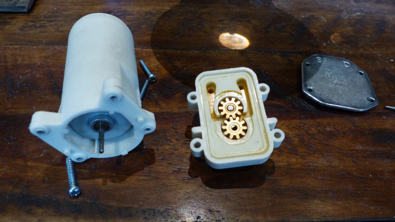
The motor runs when disconnected from the pump. It struggles but runs when the motor shaft is inserted through the rubber seal in the pump, and chokes when brass gear is on the shaft even if the other gear is missing. Couldn't get the motor out without breaking the housing so that's as far as I went. I'm just assuming the pump puts too much load on a cheap-ass motor.
Anyway, the testing with the DMM showed that the 2 diodes wired in series will work, so I went ahead and soldered up the pump power wire.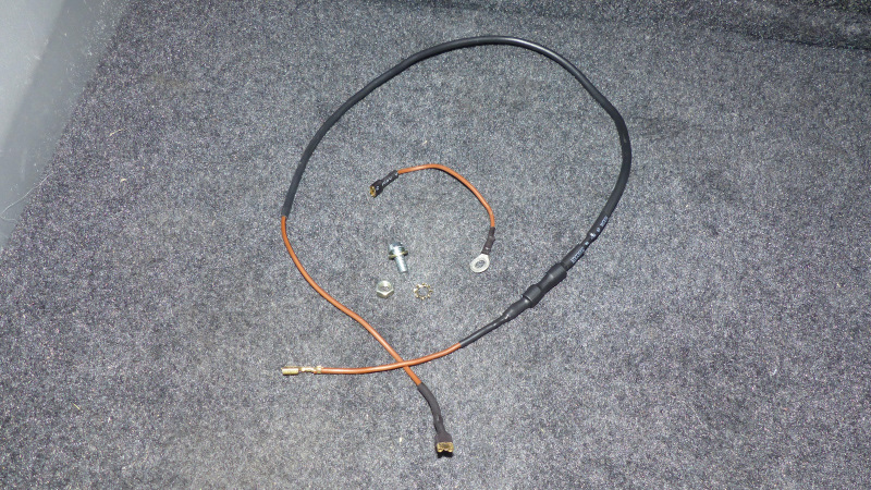
I have a VDO pump on order so will have to wait for that before I can finish this up.
Posted by: bbrock Aug 13 2022, 07:44 PM
Well that escalated quickly 
The new VDO pump came yesterday so this morning I went out to the garage just like last Saturday, thinking I'd spend 15 minutes tops swapping out the windscreen pumps and declare victory on this project. Two hours later I had this:
So what happened? Well, when I installed the new pump, it wouldn't engage pulling back on the wiper lever. More curious, the flick wipe feature was being reluctant too. I pulled the pump and hooked it up to my power supply and couldn't get it to run. I knew it was unlikely both the URO and new pump were bad, so I did what anyone with half a brain would have done last week - hook it directly to the battery. Yep, fired right up. Grabbed the URO pump and did the same. Yep, works fine. Turns out my cheap power supply just wasn't pumping enough amps to get the pumps going. Could have saved $50 had I done that last weekend. However, the VDO pump is much quieter than the URO. The URO screams so loud, it made me jump a couple times when I used it while driving. So I'm not that upset I bought the VDO. Anyway, so what the hell?
I unhooked the pump and checked voltage on the end of the brwn/blk wire again. 12v when the lever was pulled. Hooked the pump back up. Less than 1v. Hmmm. I cut open the brwn/blk wire so I could bypass the diodes to rule them out. Same results. I cut the diodes out completely just to make sure they weren't draining power somehow. Nope, same thing. I had an idea of what might be happening but continued to troubleshoot everything in the fuel compartment before acting on my hunch. Ground was good. Everything was connected correctly and working fine as long as the pump wasn't connected. Okay, time to pull the wiper switch.
I swear I took a pic of the switch inside the wiper control assembly but apparently not. Anyway, it is easy to see and is part of the same mechanism that pushes the plunger on the valve for the pneumatic washer gizmo. When the switch is in zero position and the lever is pulled back, there should be zero resistant between the terminals that connect to the red/blk and brwn/blk wires on the harness. I was getting varying resistance values, but always resistance. Then on the harness side, I connected a very small gauge jumper between the same wires on the connector socket on the harness and turned on the key. Flick wipers ran. Now I connected the pump and tried again. The little jumper got hot as hell and I yanked it. So my hunch was correct. The switch in the wiper assembly isn't rated for the amperage needed to start those pumps. I figured I'd probably fried the switch but I have spares so wasn't worried. On close inspection, it made more sense. There was a spot of carbon on the contact of the switch. Apparently running the pump directly off that switch was causing it to spark and build up carbon until the resistance was too high to flow enough current. After cleaning off the contact with a little 1000 grit polishing paper and a spray with contact cleaner, I was consistently getting 0 ohms resistance with the lever pulled back.
The solution, of course, was to add a relay so I grabbed the relay that came with the Car Magic kit and set about designing the circuit. Where to get power and ground without running wires all over the place which is part of what I wanted to avoid? Everything I needed was right there in the intermittent relay socket which would make for a nice, compact install. Here's the fully functioning test circuit. Pretty, ain't it? 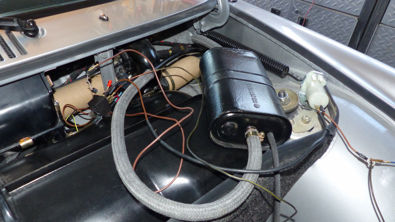
Let's fix up some connections to tidy things up. The relay coil still creates a path to ground, so I still needed the diodes to fully disconnect the brwn/blk wire for the intermittent function to work. Since the brwn/blk was now just switching on the relay, I went back to the 1N4001 diodes because they are smaller so easier to solder and shrink wrap. Then a couple pigtail connections to split power and ground off the intermittent relay. I also changed the wire from the relay to the pump to red/blk to reflect it is switched power. Here's the full spread of all the bits. This could easily be done up as a kit. I'm not doing it, but if anyone else wants to, please do.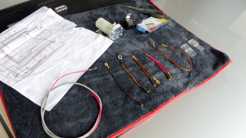
After tidying things up with the new connectors, I gave everything another test to make sure all was working before putting the fuel compartment back together. Washers worked, flick wiper worked, intermittent wiper worked... and kept working. Intermittent wipers never turned off. WTF? That meant the brwn/blk wire wasn't grounded in positions 0-2 as it should be. As soon as I looked inside the car and saw the wiper switch assembly dangling on the harness, I knew what the deal was. You know that weird little copper tab on the wiper switch that gets lost and causes trouble? Yeah, that's where the brwn/blk wire connects to ground. Mystery solved. After putting the column switches back together, everything worked as it should. Only thing left was to button everything up. Here's what the final installation of the relay looks like. Very stealth and very factory looking. 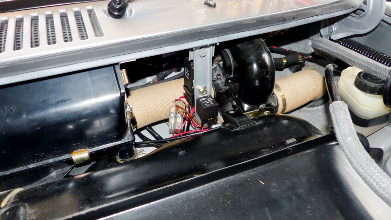
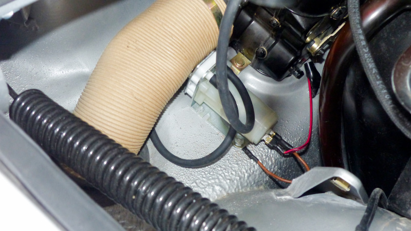
I'll write up a how-to on this. Was it easier than installing the Car Magic kit? Of course not. I like the install better though. Less drilling/molesting the car, less wire strung around, and everything is color matched to the factory scheme. It will also be a little cheaper and a LOT easier than the Car Magic kit for the next person. R&D can be a bitch.  Thanks to everyone for helping work through this project. It was really pretty fun.
Posted by: FlacaProductions Aug 13 2022, 10:29 PM
Very cool - and everyone likes a graceful recovery! Good troubleshooting.
Posted by: davep Aug 13 2022, 10:31 PM
A very interesting discussion. I have been kicking this around in my head for years, but had other priorities. However, years ago I 3-D printed a switch mount to replace the water valve on the wiper switch assembly. This gave me the trigger for the pump. I believe the switch (a tiny momentary pushbutton) does not have the necessary current capacity, so an additional relay would be needed to actually power the pump. I also 3-D printed a disc to fit in the washer tank cap to allow the tank to vent; this allows us to use the regular 914/4 washer tank with just a simple and reversible modification. All I have left to do is figure out the wire lengths and route it. I could have 20 sets of these parts available.
http://www.914world.com/bbs2/index.php?showtopic=67916&st=29#
Posted by: bbrock Aug 13 2022, 11:33 PM
A very interesting discussion. I have been kicking this around in my head for years, but had other priorities. However, years ago I 3-D printed a switch mount to replace the water valve on the wiper switch assembly. This gave me the trigger for the pump. I believe the switch (a tiny momentary pushbutton) does not have the necessary current capacity, so an additional relay would be needed to actually power the pump. I also 3-D printed a disc to fit in the washer tank cap to allow the tank to vent; this allows us to use the regular 914/4 washer tank with just a simple and reversible modification. All I have left to do is figure out the wire lengths and route it. I could have 20 sets of these parts available.
http://www.914world.com/bbs2/index.php?showtopic=67916&st=29#
I just realized I never posted a link to the http://carmagic.us/washer.html I keep mentioning in this thread. I added it in the first post starting the thread have added it here too. That kit sounds just like what you are describing, including he little disc to vent the bottle. I know several people have installed these and really like them.
I decided not to use it after reading SirAndy's tech article on adding an electric windshield pump. There I learned there is already an electrical switch inside the wiper switch assembly that can be used to trigger the pump. Even better is that most 914s already have a wire running from that switch to fuel compartment to trigger a relay when the wiper lever is pulled back. Figuring out how to get that to work with the optional intermittent wiper feature was a little tricky as the last four pages show.
The CarMagic kit requires too much drilling for my taste. This method only requires a single hole drilled to screw the pump to the chassis. The installation also doesn't require touching anything inside the cabin of the car except to pull or clip the water hoses from the switch valve, which I was able to do from under the dash. The rest is all done up front in the fuel tank compartment.
I'm kind of psychotic about wiring and making modification be as stealth as possible, so I used a little different approach for venting the bottle. I ran a drill down the small hole that is already in bottle cap and then drilled two small holes from the side into the channel created to turn it into a vented cap. Here you can see the drill bit sticking out the original hole and can just see it through one of the side holes.
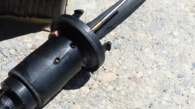
I also left the tube from the cap to tire attached to the bottle to pay homage to the fantastically quirky pneumatic system that I regret having to replace. It's really there for the stealth effect, but does have a practical purpose in creating a tether for the bottle cap so it doesn't fall down into the fuel compartment when refilling the bottle. If I connected it to the spare tire, that hose also has a schrader valve in it that can be used to refill the spare without having to dig out you luggage and lift the frunk board. I'm not using that feature but might if I take a long trip with a frunk full of luggage. When everything is back together, this setup is completely stealth and looks like an ordinary spare tire powered washer system. Here's what my now electrified washer system using an unmodified stock wiper switch looks like.
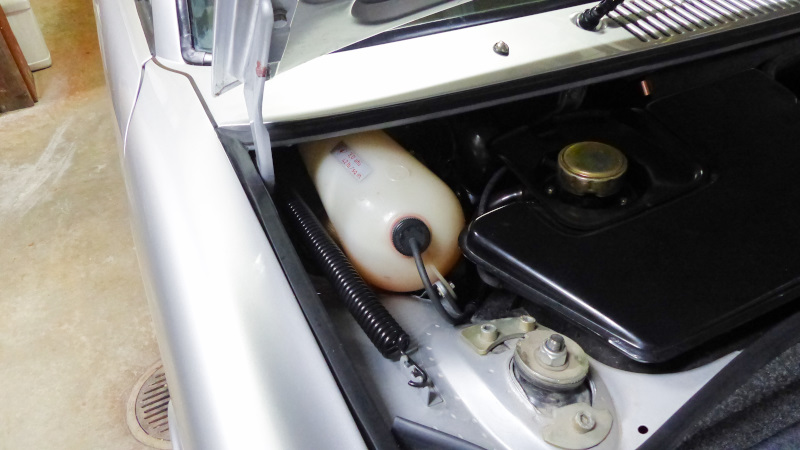
Posted by: Superhawk996 Aug 14 2022, 08:38 AM
 Bookmarking this thread.
Posted by: 930cabman Aug 14 2022, 09:30 AM
Well that escalated quickly
The new VDO pump came yesterday so this morning I went out to the garage just like last Saturday, thinking I'd spend 15 minutes tops swapping out the windscreen pumps and declare victory on this project. Two hours later I had this:
So what happened?
Well, when I installed the new pump, it wouldn't engage pulling back on the wiper lever. More curious, the flick wipe feature was being reluctant too. I pulled the pump and hooked it up to my power supply and couldn't get it to run. I knew it was unlikely both the URO and new pump were bad, so I did what anyone with half a brain would have done last week - hook it directly to the battery. Yep, fired right up. Grabbed the URO pump and did the same. Yep, works fine. Turns out my cheap power supply just wasn't pumping enough amps to get the pumps going. Could have saved $50 had I done that last weekend. However, the VDO pump is much quieter than the URO. The URO screams so loud, it made me jump a couple times when I used it while driving. So I'm not that upset I bought the VDO. Anyway, so what the hell?I unhooked the pump and checked voltage on the end of the brwn/blk wire again. 12v when the lever was pulled. Hooked the pump back up. Less than 1v. Hmmm.
I cut open the brwn/blk wire so I could bypass the diodes to rule them out. Same results. I cut the diodes out completely just to make sure they weren't draining power somehow. Nope, same thing. I had an idea of what might be happening but continued to troubleshoot everything in the fuel compartment before acting on my hunch. Ground was good. Everything was connected correctly and working fine as long as the pump wasn't connected. Okay, time to pull the wiper switch.I swear I took a pic of the switch inside the wiper control assembly but apparently not. Anyway, it is easy to see and is part of the same mechanism that pushes the plunger on the valve for the pneumatic washer gizmo. When the switch is in zero position and the lever is pulled back, there should be zero resistant between the terminals that connect to the red/blk and brwn/blk wires on the harness. I was getting varying resistance values, but always resistance. Then on the harness side, I connected a very small gauge jumper between the same wires on the connector socket on the harness and turned on the key. Flick wipers ran. Now I connected the pump and tried again. The little jumper got hot as hell and I yanked it. So my hunch was correct. The switch in the wiper assembly isn't rated for the amperage needed to start those pumps. I figured I'd probably fried the switch but I have spares so wasn't worried. On close inspection, it made more sense. There was a spot of carbon on the contact of the switch. Apparently running the pump directly off that switch was causing it to spark and build up carbon until the resistance was too high to flow enough current. After cleaning off the contact with a little 1000 grit polishing paper and a spray with contact cleaner, I was consistently getting 0 ohms resistance with the lever pulled back.
The solution, of course, was to add a relay so I grabbed the relay that came with the Car Magic kit and set about designing the circuit. Where to get power and ground without running wires all over the place which is part of what I wanted to avoid? Everything I needed was right there in the intermittent relay socket which would make for a nice, compact install. Here's the fully functioning test circuit. Pretty, ain't it?
Let's fix up some connections to tidy things up. The relay coil still creates a path to ground, so I still needed the diodes to fully disconnect the brwn/blk wire for the intermittent function to work. Since the brwn/blk was now just switching on the relay, I went back to the 1N4001 diodes because they are smaller so easier to solder and shrink wrap. Then a couple pigtail connections to split power and ground off the intermittent relay. I also changed the wire from the relay to the pump to red/blk to reflect it is switched power. Here's the full spread of all the bits. This could easily be done up as a kit. I'm not doing it, but if anyone else wants to, please do.
After tidying things up with the new connectors, I gave everything another test to make sure all was working before putting the fuel compartment back together. Washers worked, flick wiper worked, intermittent wiper worked... and kept working. Intermittent wipers never turned off. WTF? That meant the brwn/blk wire wasn't grounded in positions 0-2 as it should be. As soon as I looked inside the car and saw the wiper switch assembly dangling on the harness, I knew what the deal was. You know that weird little copper tab on the wiper switch that gets lost and causes trouble? Yeah, that's where the brwn/blk wire connects to ground. Mystery solved. After putting the column switches back together, everything worked as it should. Only thing left was to button everything up. Here's what the final installation of the relay looks like. Very stealth and very factory looking.
I'll write up a how-to on this. Was it easier than installing the Car Magic kit?
Of course not. I like the install better though. Less drilling/molesting the car, less wire strung around, and everything is color matched to the factory scheme. It will also be a little cheaper and a LOT easier than the Car Magic kit for the next person. R&D can be a bitch. Thanks to everyone for helping work through this project. It was really pretty fun.I may be able to piece together an original washer system if you like, cheap!!
Posted by: bbrock Aug 14 2022, 11:32 AM
I may be able to piece together an original washer system if you like, cheap!!
I'm way past that of course. Countless hours and $ wasted trying to refurbish the old system. First problem was hoses. You need washer hose that can withstand 42 psi and it turns out that is not easy to find. I finally tracked down some NOS hose. Next problem was the valve in the wiper switch assembly. I have three wiper switches and the valves were blocked and wouldn't function. Try soaking in vinegar and Lime Away without luck so I bought a repro CIP1 valve. It leaks. Not into the cabin, but through the system so the washer nozzles constantly ooze liquid until the bottle was empty. In hind sight, I probably spent 3x as much time an money trying to get the original system to work as I did figuring out this one.Now that the system is worked out, this conversion should be possible for $40-$70 in parts depending on which pump you choose, and ~2-3 hours if you are already familiar with crimping wire connectors etc., add an hour if you are not.
I do miss the brilliant stupidity of the tire system though.
Powered by Invision Power Board (http://www.invisionboard.com)
© Invision Power Services (http://www.invisionpower.com)