Printable Version of Topic
Click here to view this topic in its original format
914World.com _ 914World Garage _ 2056 rebuild part THREE
Posted by: rfinegan Feb 6 2023, 07:38 AM
Here is a link to part one:
http://www.914world.com/bbs2/index.php?showtopic=351117&hl=2056
I decide my t1 oil pump in my 2056 was doing me no favors with a smaller than ideal OD.
I still had the T4 oil pump from the 2.0 that was doing its job when I had a cam thrust bearing fail /knock, so I decided to pull it a part for inspection.
I will perform some measurements and get it cleaned up, if it turns out to be in good shape.
The pics look like a great core.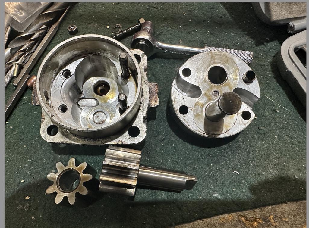
Posted by: Superhawk996 Feb 6 2023, 07:50 AM
Agree - looks like a pretty good core.
Pin the idler shaft.
Mandatory reading:
https://www.thesamba.com/vw/forum/viewtopic.php?t=699156
Posted by: rfinegan Feb 6 2023, 08:04 AM
Great link, this should be a sticky if its not there already

Agree - looks like a pretty good core.
Pin the idler shaft.
Mandatory reading:
https://www.thesamba.com/vw/forum/viewtopic.php?t=699156
Posted by: rfinegan Feb 6 2023, 08:33 AM
Here are come pics of case split and inspections 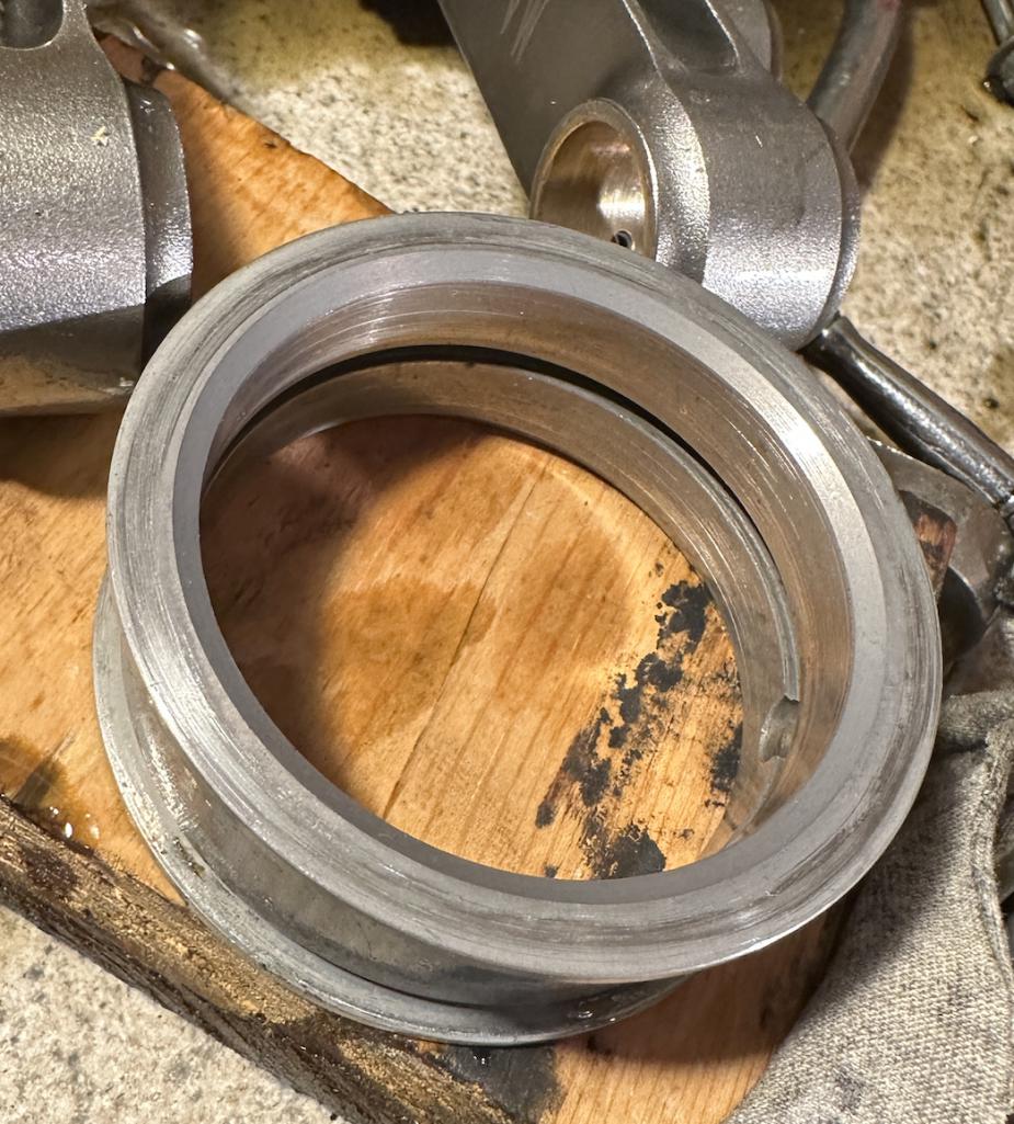
Posted by: rfinegan Feb 6 2023, 08:35 AM
another of the saddle and low pin locator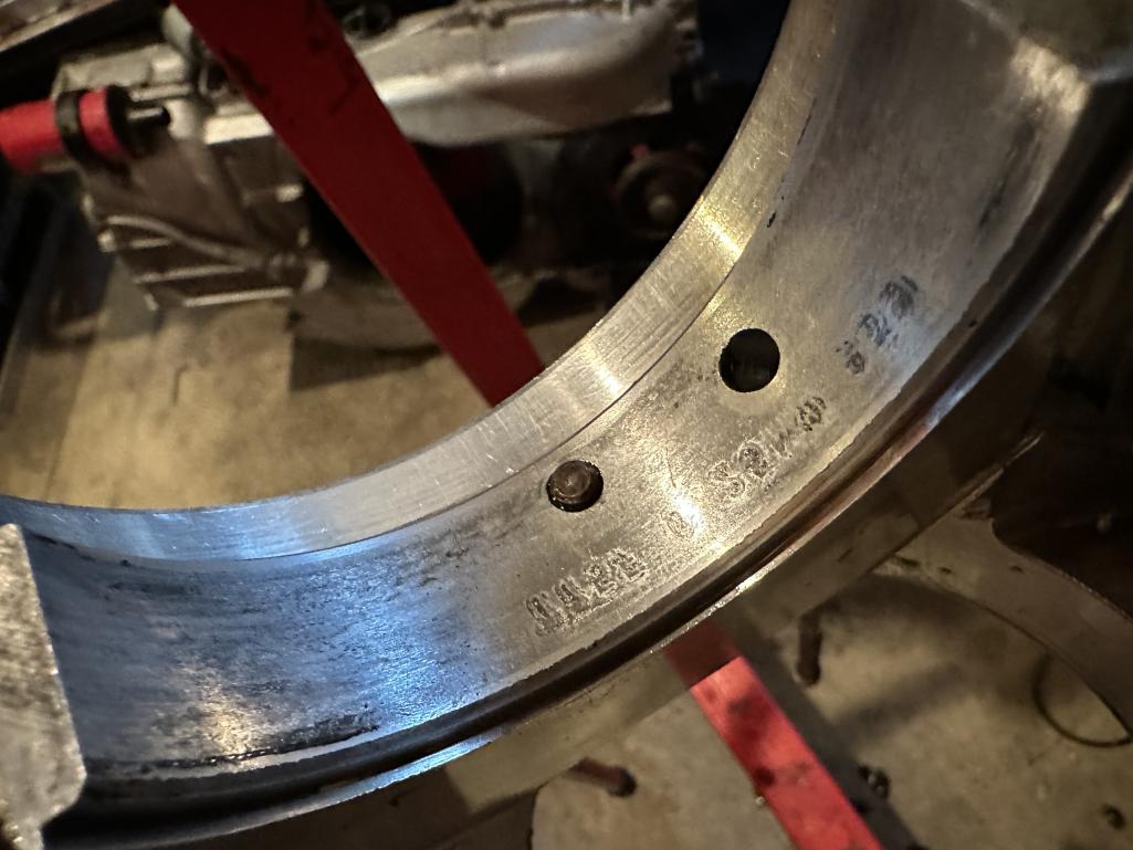
Posted by: rfinegan Feb 6 2023, 08:37 AM
rear thrust again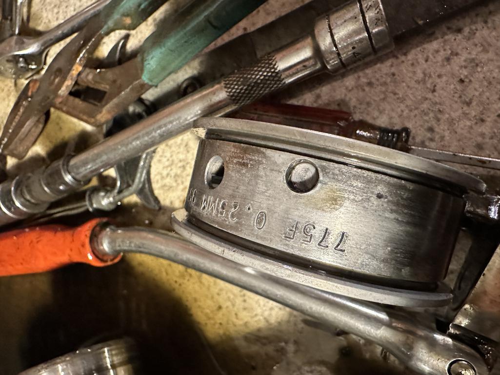
Posted by: rfinegan Feb 6 2023, 08:44 AM
and a video :
https://www.youtube.com/watch?v=dJ_iKZHldNk
Posted by: DRPHIL914 Feb 6 2023, 09:09 AM
so what are your impressions of your observations pictured here? how many miles since it had been rebuilt, it seems like just recently you completed that rebuild?
Phil
Posted by: rfinegan Feb 6 2023, 09:42 AM
Phil,
This build and the last build had a total of less that 100 miles the Failure again was the top end intake valves and guides. Ill post pic of the worn out valve guides
The bottom end seemed OK. but erratic oil pressure problems I am sure added to the guides issue
Also The Crank end play had .0045 when assembled and CHECKED
I added the rear main and the play went to zero . Sound like a familiar thread others have seen.... I continued any way thinking the seal was adding the buffer to the clearance. I had howling bear noises and the wear pic on the side of the thrust confirmed it was tight. Looks like new bearings and pump for bottom end I will check the saddles for possible line bore
Posted by: rfinegan Feb 6 2023, 09:45 AM
Here is the worst of the intake guide #1. The exhaust guilds are fine at .001 t o .0015
This intake is at .006 to .007. This was only less that 100 miles and were NEW
https://www.youtube.com/watch?v=Y7KPNeAiRig
Posted by: rfinegan Feb 6 2023, 09:48 AM
I have a new local shop add new intake guides and intake valves if needed
Posted by: rfinegan Feb 6 2023, 09:53 AM
My summary of this build:
1) OIL pressure problems
2) Oil type problem ZR1 20w50
3) Temperature problems
4) Bad intake guides
or all the above
When she ran it ran VERY well power, speed no spark knock. FUN
Valvses would stick and dead cylinders till next run
Posted by: DRPHIL914 Feb 6 2023, 10:13 AM
Phil,
This build and the last build had a total of less that 100 miles the Failure again was the top end intake valves and guides. Ill post pic of the worn out valve guides
The bottom end seemed OK. but erratic oil pressure problems I am sure added to the guides issue
Also The Crank end play had .0045 when assembled and CHECKED
I added the rear main and the play went to zero . Sound like a familiar thread others have seen.... I continued any way thinking the seal was adding the buffer to the clearance. I had howling bear noises and the wear pic on the side of the thrust confirmed it was tight. Looks like new bearings and pump for bottom end I will check the saddles for possible line bore
interesting about the guide wear, and the crank end play. I now have 2500 miles and recently had developed what i think is a RMS leak - again, after replacing it when i did the transmission seals about 10 months ago. So last night i pullted the motor and today will pull of the trans to look at that and im going to check the cranksaft endplay , i have heard that too much play will cause the leak, but maybe itd just a bad VR seal so i got new Ehrling.
am i correct that the crank endplay should be tested with no seal? i might as well check it before i even pull the flywheel, it its in spec i can recheck without new seal,
re-install seal and flywheel and the double check again , correct? lets hope its all still good i am hoping for just a seal replacment. Like you my motor running good. these are new AA head casings with brand new br seats, sterlite valves and new porsche guides with solid spacers etc. 2056 all new KB pistons hastings rings new cylinders etc. - anyway iver been watching and reading your postings . and re-reading since i will also be putting back together the original motor for a stock numbers matching correct build , thats for later. Oh the guy that assembled my short block said wht i have the other OEM heads done by another machine shop the guidse were off some wer too tight and some were too loose and that shjop(eagle machine in atlanta) said they were sourced from Porsche. My new guy made sure the new guides were perfect before installing them both on my old original rebuilt heads and these new AA casting heads on the 2056.
PHil- what is hte proper end play i am looking for for the crankshaft end play?
Posted by: Jack Standz Feb 6 2023, 11:31 AM
Crankshaft float s/b .004" plus or minus .001".
One thing to do, to reduce the RMS potential for a leak, is to use the proper installation tool. Got away without using one before for years, but am now convinced of the value now (don't you hate having to drop an engine and transmission to fix a leak?).
Hear's why:
https://gowesty.com/blogs/article-library/flywheel-or-rear-main-seal-story
Here's the tool:
https://gowesty.com/products/rear-main-seal-install-tool?_pos=1&_sid=2653a61af&_ss=r
Best wishes for getting her fixed!
Posted by: rfinegan Feb 6 2023, 11:32 AM
check in without seal and again once the seal is installed. should be the same.
0.0027 to 0.0051. most shoot for 0.004”
Place the thinnest shim in the center of the three shim pack.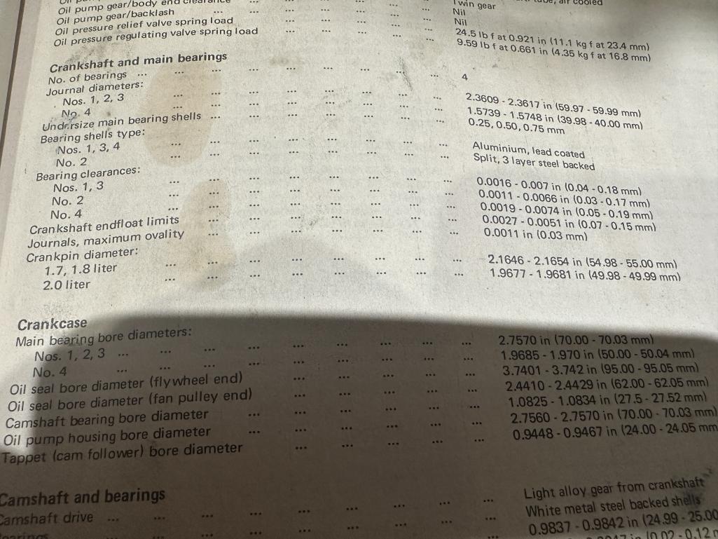
Posted by: 914sgofast2 Feb 6 2023, 12:36 PM
Here is the worst of the intake guide #1. The exhaust guilds are fine at .001 t o .0015
This intake is at .006 to .007. This was only less that 100 miles and were NEW
https://www.youtube.com/watch?v=Y7KPNeAiRig
Did the shop that installed the new valves and valve guides fail to ream the guides after the guides were pressed into the heads? Did they mix up the intake and exhaust valve guides? I think the guides are different diameters, like 8 mmm and 9 mm, so they are difficult to tell apart.
Posted by: Geezer914 Feb 6 2023, 02:56 PM
Rear main seal tool, use a block of wood. Go easy and make sure it's not cocked, flush with the case. End play, shoot for .003.
Posted by: porschetub Feb 7 2023, 03:23 PM
Rear main seal tool, use a block of wood. Go easy and make sure it's not cocked, flush with the case. End play, shoot for .003.
Yep that works,I use a small amount of engine oil on the outside of the seal then start it in by hand level then use my soft "dead blow " mallet to tap it in flush with the case,done this for years and never had an issue.
I don't know about the fit of the VR orange seal in a T4 cause I don't use them anymore after experiencing a very poor fit in my 911 engine ,it was so loose I pushed it in by hand
 the Elring replacement got the mallet treatment and not leaking a I'am sure the VR one would have leaked .
Also make sure the flywheel seal running surface is nice and smooth and lubed up and the o ring area is clean before fitting and lightly oiled.
Front seals don't really give issues unless they are just plain worn out ,if so you end up with a shitty mess in the fan housing ,fan ,cooler and across the barrels,certainly worth cleaning up right,cheers.
Posted by: rfinegan Feb 9 2023, 01:27 PM
GREAT info on the rear main seal. ..with mods
https://www.facebook.com/1160006259/videos/5098274283572774/
Posted by: rfinegan Feb 14 2023, 03:16 PM
Happy day for a change in the garage
A world member set me up with a 4 post yoke for the engine stand (Thanks Nick)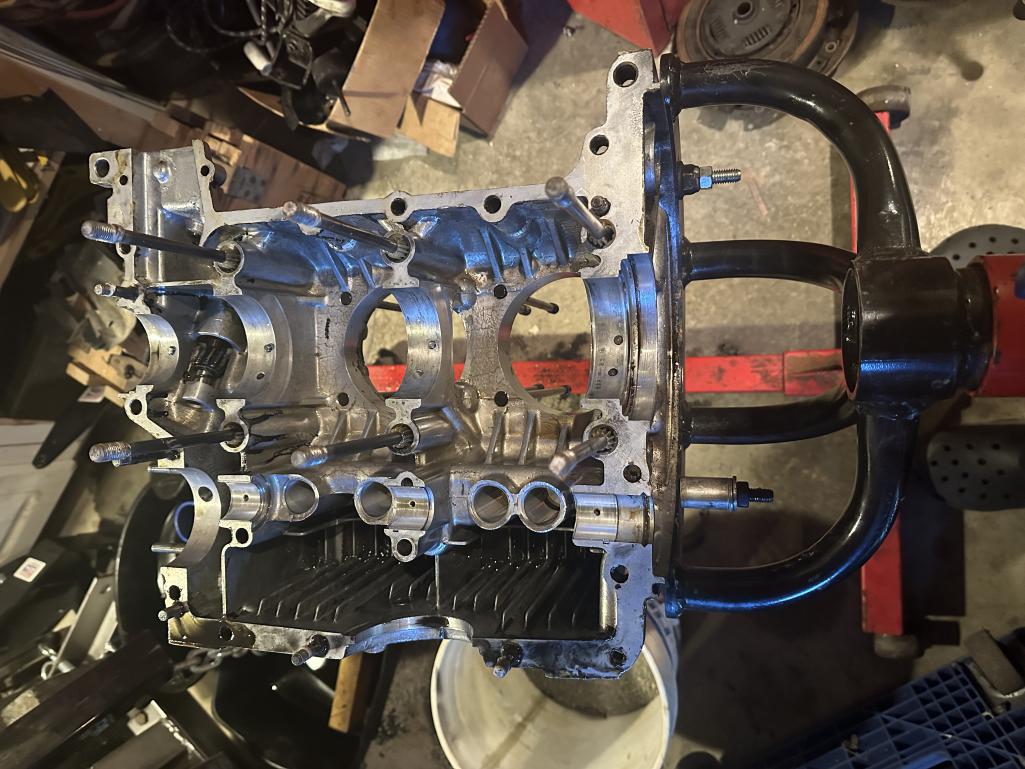
Posted by: NARP74 Feb 14 2023, 03:46 PM
What were your thoughts on the wrong oil? Why did you mention that?
Posted by: 914sgofast2 Feb 14 2023, 03:51 PM
From your picture of the engine case mounted in the new stand, you might want to do a little research to find a cure for the RMS leak problem.
Take a look at the posts in the Facebook "4th Dimension Type 4 Porsche/VW Performance Group" or do a YouTube search for Jake Raby's video about how to fix leaking rear main seals on Type 4 engines. I recently saw that video and was surprised by Jake's comments.
Raby files two very small relief passages above and below the rear main bearing saddle area on one side the engine case to allow oil a path to drain out of the cavity between the main bearing and the seal/crank spacers so the rear main seal stays oil tight. Raby says the factory oil drain hole is too high in this area, as well as lacking any way for air to enter the cavity so the oil can drain back into the sump, thereby creating an air lock which prevents the oil in that area from escaping unless it forces its way past the rear main seal lip. Raby also said that while the factory started using a drain hole in the 2 liter cases, it never put a drain hole in the earlier 1.7 & 1.8 liter cases. Raby further claims the factory's drain hole in the 2 liter cases was too small in diameter and located too high in the bearing saddle area to properly drain the oil back into the sump.
He also said it really doesn't matter what brand of seal you use (Victor Reinz or Elring) these days if you don't make the new oil drain passages he described in his video. However, Raby does mention that the black SABO brand seals are no longer any good and should now be completely avoided because the SABO factory's seal mold has worn out. Another thing he mentioned is that the width of the rear main seals is different because the VW Type 4 engine cases and the Porsche engine cases take different width seals because of the different sizes of the flywheel & pilot bearings in the two types of engines.
Raby said he now uses a proprietary rear main seal he gets from one of his customers who sells all types of industrial seals. Raby uses that "mystery special" seal on all the Type 4 engines he builds these days. Raby won't sell it to the public (nor does the Type 4 Store) and Raby said it comes from an unnamed military helicopter's drive unit.
Posted by: rfinegan Feb 14 2023, 04:32 PM
I was thinking the VR1 20W50 was not the best oil for break in. Also may bypass the oil pressure controls to the cooler when cold and possibly longer with the 30mm pump.
Some-thing wore out all my NEW intake guides in less than 100 mile...
Total worn out!
What were your thoughts on the wrong oil? Why did you mention that?
Posted by: NARP74 Feb 14 2023, 04:38 PM
I was thinking the ZR 20W50 was not the best oil for break in. Also may bypass the oil pressure controls to the cooler when cold and possibly longer with the 30mm pump.
Some-thing wore out all my NEW intake guides in less than 100 mile...
Total worn out!
What were your thoughts on the wrong oil? Why did you mention that?
OK, thanks
Posted by: rfinegan Feb 14 2023, 04:38 PM
I linked to the Raby live stream in post 19
Now that I'm on the stand I will cut the drains on the one case 1/2 but I did not have issues with my rear leaking. Thanks for descriptive tips...
From your picture of the engine case mounted in the new stand, you might want to do a little research to find a cure for the RMS leak problem.
Take a look at the posts in the Facebook "4th Dimension Type 4 Porsche/VW Performance Group" or do a YouTube search for Jake Raby's video about how to fix leaking rear main seals on Type 4 engines. I recently saw that video and was surprised by Jake's comments.
Raby files two very small relief passages above and below the rear main bearing saddle area on one side the engine case to allow oil a path to drain out of the cavity between the main bearing and the seal/crank spacers so the rear main seal stays oil tight. Raby says the factory oil drain hole is too high in this area, as well as lacking any way for air to enter the cavity so the oil can drain back into the sump, thereby creating an air lock which prevents the oil in that area from escaping unless it forces its way past the rear main seal lip. Raby also said that while the factory started using a drain hole in the 2 liter cases, it never put a drain hole in the earlier 1.7 & 1.8 liter cases. Raby further claims the factory's drain hole in the 2 liter cases was too small in diameter and located too high in the bearing saddle area to properly drain the oil back into the sump.
He also said it really doesn't matter what brand of seal you use (Victor Reinz or Elring) these days if you don't make the new oil drain passages he described in his video. However, Raby does mention that the black SABO brand seals are no longer any good and should now be completely avoided because the SABO factory's seal mold has worn out. Another thing he mentioned is that the width of the rear main seals is different because the VW Type 4 engine cases and the Porsche engine cases take different width seals because of the different sizes of the flywheel & pilot bearings in the two types of engines.
Raby said he now uses a proprietary rear main seal he gets from one of his customers who sells all types of industrial seals. Raby uses that "mystery special" seal on all the Type 4 engines he builds these days. Raby won't sell it to the public (nor does the Type 4 Store) and Raby said it comes from an unnamed military helicopter's drive unit.
Posted by: rfinegan Feb 19 2023, 01:32 PM
Trying to keep the motivation up on this holiday week end....
Posted by: rfinegan Feb 19 2023, 01:38 PM
Posted by: barefoot Feb 19 2023, 05:47 PM
You keep your tools in the dark ??
Posted by: rfinegan Feb 19 2023, 06:45 PM
Old trick of the trade...no one asks to borrow any tools!
Posted by: r_towle Feb 19 2023, 07:21 PM
This will be the third build?
Curious about breakin methods for the cam/lifters.
Rich
Posted by: rfinegan Feb 20 2023, 07:04 AM
Rich,
Yep this is # 3 and the $1000 dollar question:
Do I reuse the Cam?
Do I reuse the Lifters?
Do I get new Lifters?
All new?
or all new and another cam profile?
first start:
http://www.914world.com/bbs2/index.php?s=&showtopic=351117&view=findpost&p=2939711
I will for sure show the inspection and be asking for advice as we get to this very soon...
The first run was with the supplied cam lube and 20 min burn in @ 2500 rpm with variation to speed slightly to keep the oil flying in all directions .Followed by tuning and re torque of the heads prior to installation in car... video in part one
Second time was the above cam and lifters ( matched to lobes and lifter bores in SAME locations) with assembly lube and 15 burn in @ 2500 rpm
This will be the third build?
Curious about breakin methods for the cam/lifters.
Rich
Posted by: rfinegan Feb 21 2023, 04:03 PM
Heads are repaired with new intake guides and 3 angle valve job (300.00):-)
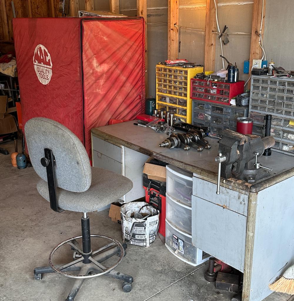
NOT A CLEAN ROOM but good for measuring and inspection...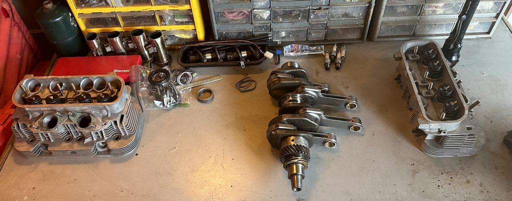
Posted by: Cairo94507 Feb 22 2023, 08:35 AM
I have my fingers and toes crossed this motor purrs perfectly for you. 
Posted by: rfinegan Feb 22 2023, 09:36 AM
I will be having a sale on engine parts it it doesn’t...  Thanks for the Positive motivation

I have my fingers and toes crossed this motor purrs perfectly for you.
Posted by: rfinegan Mar 4 2023, 08:24 AM
I did some detailed measuring on the con rod journals, but instead or re writing, Ill post a link
https://www.facebook.com/groups/type4ever/permalink/3393206420997827/
Posted by: 914rrr Mar 4 2023, 08:59 AM
Lots of great info on this thread! Good luck!
Posted by: rfinegan Mar 27 2023, 05:24 AM
It took a while but I finally got a set of NOS KS/KW 0.010 main bearings on the way....
I did have to pay more than I should have....but I think I am worth it! ;-)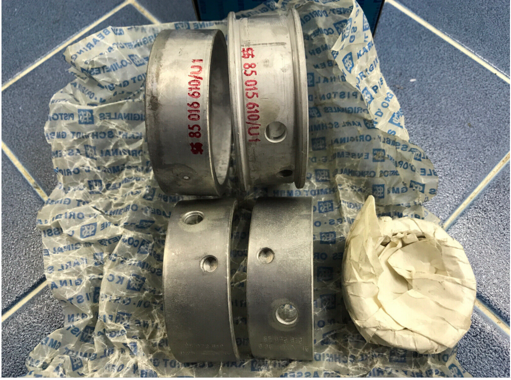
Posted by: rfinegan Mar 27 2023, 05:29 AM
Thanks to the generosity of a Kerry, world member here (White1975) and the loan of a T4 timing gear puller. I have the old bearings off and will be ready for the new bearings when they arrive
WooHoo
Posted by: rfinegan Mar 27 2023, 06:26 AM

Posted by: rfinegan Mar 28 2023, 05:54 PM
Add a VDO HEAD TEMP thermocouple under the #3 spark plug. Milled a small hole for the wires and crimp.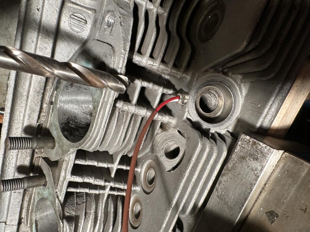
Posted by: VaccaRabite Mar 29 2023, 06:09 AM
Unless things have changed, the VDO head temp gauges are not good, and are not temp compensated. I'd strongly consider using a quality head temp gauge like the Dakota Digital (or at least a temp compensated gauge.)
Milling a hole like that is, IMO, not better then cutting a groove in the boss for the K type sender. And when you decide that you are tired of the VDO CHT lying to you and want to change it out for a better one, you are going to be very unhappy when you go to remove and install a new K type sender.
Zach
Posted by: rfinegan Mar 29 2023, 07:18 AM
This way the sensor stays in place when servicing the plugs. Clean and EZ. IF this was a 2.0l FI head, a grove should be the way I would have gone too. It was simple to install by pulling the terminals out of the connector. It should be serviceable with the tins in place with long tiny bent hemostats or pliers
Thanks for the tip on the Dakota. If they made a matching gauge for my console I would give them a try but at this point I’m all analog and Black /White (no digital) VDO is beter than running blind
Posted by: rfinegan Mar 29 2023, 11:11 AM
Never opposed to OE parts if you can get them....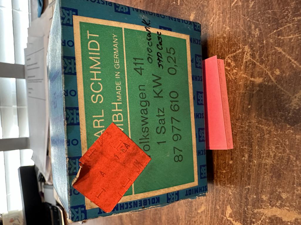
Posted by: rfinegan Apr 7 2023, 11:06 AM
I may be CRAZY, but got a set of ML Cam bearings now...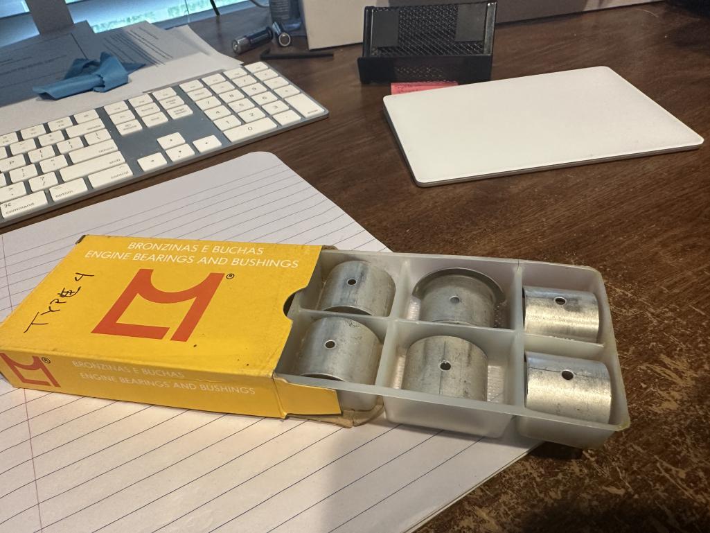
Posted by: rfinegan Apr 7 2023, 11:07 AM
NEW KS 2.0 rod bearing are HERE....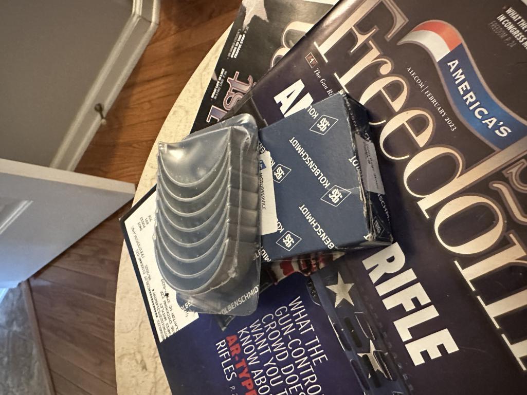
Posted by: rfinegan Jun 21 2023, 04:50 PM
Just got a new tube of valve lapping paste...The old one lasted 45 years!
Tonight lapped the cylinders to the heads(no head gaskets). I did not lap last time but did have the heads fly cut each time to true.
The new intakes were recut (machine not stone) and new guides. Owner of the shop said. These will be much better than the old valve jobs. They lapped the intake , so I decide to lap the exhaust too. Look good.
I ran a thread die on all the case studs and pullout all the plugs to clean with a gun cleaning kit prior to final cleaning . Lots of cleaning , then lots more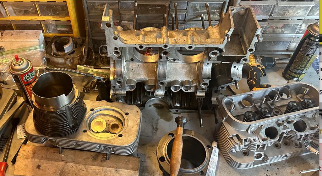
Posted by: rfinegan Jun 21 2023, 05:00 PM
KTM 125 top end upgrade in the background.....while at it for my son.
Posted by: r_towle Jun 21 2023, 05:33 PM
You keep learning all sorts of fun things!
Posted by: porschetub Jun 21 2023, 05:36 PM
Just got a new tube of valve lapping paste...The old one lasted 45 years!
Tonight lapped the cylinders to the heads(no head gaskets). I did not lap last time but did have the heads fly cut each time to true.
The new intakes were recut (machine not stone) and new guides. Owner of the shop said. These will be much better than the old valve jobs. They lapped the intake , so I decide to lap the exhaust too. Look good.
I ran a thread die on all the case studs and pullout all the plugs to clean with a gun cleaning kit prior to final cleaning . Lots of cleaning , then lots more
I don't normally lap if the heads have been fly cut and the barrels are new,but won't hurt.
Wow you have had some bad luck with this build and hopefully it will be the last , following this one,cheers.
Posted by: rfinegan Jul 9 2023, 03:48 PM
heads are disassembled cleaned and lubed and back together. ready to drop on...
Posted by: rfinegan Jul 9 2023, 03:56 PM
The windage tray had the same old seals, so a new set glued in place and ready for installation along with the cam bearings. USING A DOUBLE THRUST and setting the endplay at .002 inch flipping the bearing without out the tab 180 degree got my play set about right. The 2 shells work working against each other and canceling out he endplay important to test the play on both half and Assembly to ensure you have it just right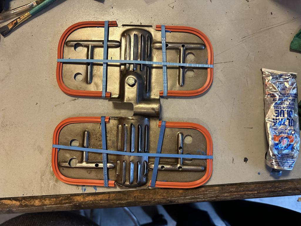
Posted by: rfinegan Jul 9 2023, 03:57 PM
vintage bearings too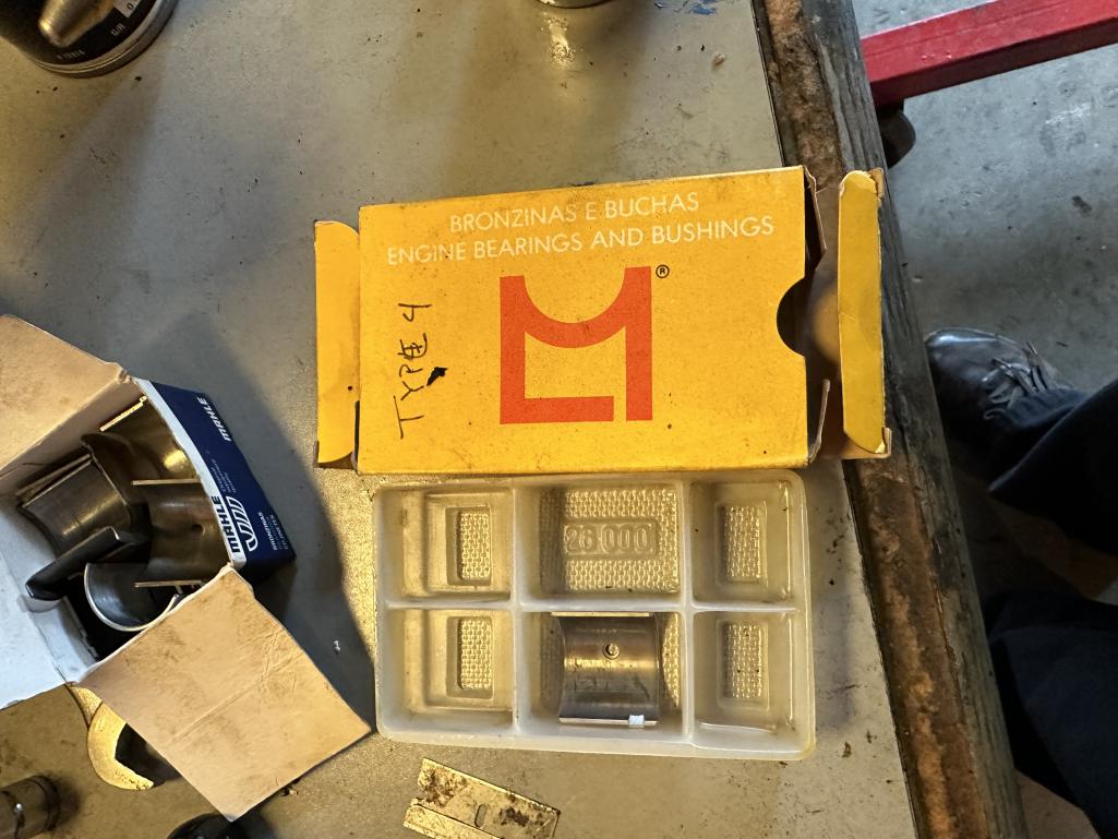
Posted by: rfinegan Jul 9 2023, 03:59 PM
here is a video of the camshaft end play
https://www.youtube.com/watch?v=WpUDEaOWWa4
Posted by: rfinegan Jul 9 2023, 04:06 PM
Measured the case, bearings and crank journals as well as plastic gage the split shells.
Case is sealed and about ready to jugs and slugs...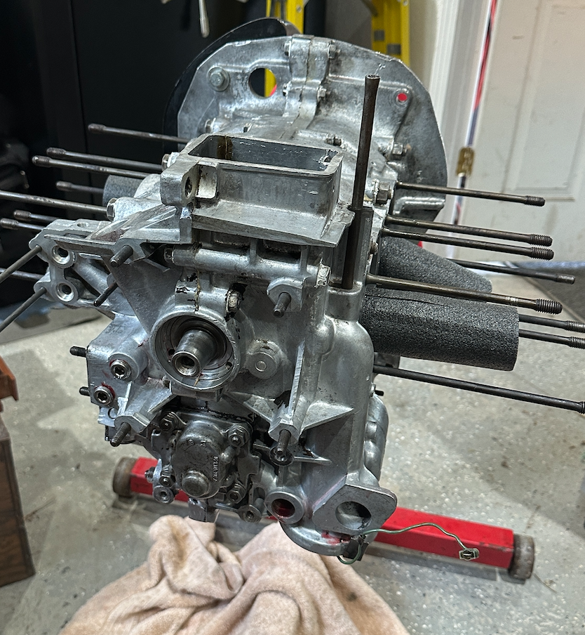
Posted by: Cairo94507 Jul 9 2023, 05:49 PM
![popcorn[1].gif](style_emoticons/default/popcorn[1].gif) Can't wait for this to be fired-up.
Can't wait for this to be fired-up.
Posted by: rfinegan Jul 10 2023, 06:02 AM
I did pin the shaft on the T4 oil pump. Drilled and milled a 3/32 hole in the housing and when I hit the hardened shaft I switched to an end mill. That shaft is hard so it just left a small mark. NO problem. A aluminum punch and hammer the shaft press out EZ. To EZ! I would pin every one of these moving forward .
With the mark I was able to grind a slot in the shaft for the pin to fit about an 1/8 inch deep with a cut off wheel. Then tapped the hole for a set screw-in the housing. Then cleaned and red lock tight the shaft back into place so the slot is seen in the hole. Intall the pin to full engagement with the new slot with more red lock tight. Installed the set screws so the pin would not come out (more red lock tight) and staked the set screw in place.
I feel confident that this pin and set screw are now part of the housing and will not come out.
After thinking about the for a moment I should have just welded the pin in place like a short barreled muzzle brake...good enough for the ATF as permanent!
Sorry no pics or vid
Posted by: rfinegan Jul 10 2023, 06:57 AM
Can't wait for this to be fired-up. YEP, Getting optimistic again. With dreams of Octeenerfest, driving on the Dragon and LARGE dyno numbers! This is a dream right?
Posted by: rfinegan Jul 17 2023, 05:30 AM
Playing with a thermal dispersion paint from Cerakote (transfer Gray)
Here:
http://www.914world.com/bbs2/index.php?showtopic=366063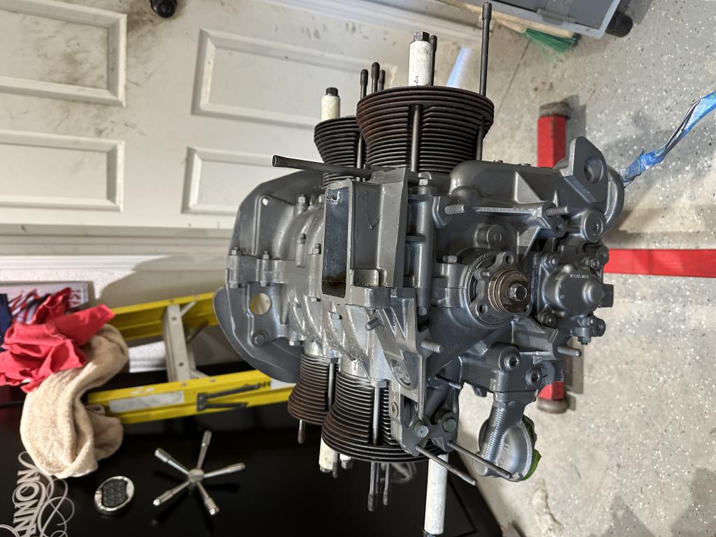
Posted by: DRPHIL914 Jul 17 2023, 06:14 AM
Can't wait for this to be fired-up. YEP, Getting optimistic again. With dreams of Octeenerfest, driving on the Dragon and LARGE dyno numbers! This is a dream right?
@http://www.914world.com/bbs2/index.php?showuser=15499
watching and learning from your experiences, Hope to see you at Okteenerfest for sure!!
at some point i need to reassemble my OEM motor that dropped the valve seat a couple years ago, and i am trying to decide if i can do that myself, i didnt crack the case i justhave to put the newly rebuilt original heads back on it and wonder if i need to lap the head if i keep the old cylinders and pistons in place, i assume i should. anyway we should get the 914s from SC and NC together and do a engine build how-to clinic!
Good luck going forward 3x is a charm right??
Posted by: rfinegan Jul 17 2023, 06:14 AM
heads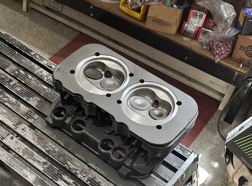
Posted by: rfinegan Jul 17 2023, 07:30 AM
Lapping the heads can only be a good thing, and you get a chance to look at the cylinder bores and pistons/rings too. AS well as resealing the case to cylinders while you are at it....top end work should go pretty EZ for people with good repair skills, even if they are new for type 4 work...Just need simple hand tools and a torque wrench and some hi temp Curel T(green) or a small dab aviation sealer ...What could go wrong....
-Cheers.
and thanks for the support
Can't wait for this to be fired-up. YEP, Getting optimistic again. With dreams of Octeenerfest, driving on the Dragon and LARGE dyno numbers! This is a dream right?
@http://www.914world.com/bbs2/index.php?showuser=15499
watching and learning from your experiences, Hope to see you at Okteenerfest for sure!!
at some point i need to reassemble my OEM motor that dropped the valve seat a couple years ago, and i am trying to decide if i can do that myself, i didnt crack the case i justhave to put the newly rebuilt original heads back on it and wonder if i need to lap the head if i keep the old cylinders and pistons in place, i assume i should. anyway we should get the 914s from SC and NC together and do a engine build how-to clinic!
Good luck going forward 3x is a charm right??
Posted by: DRPHIL914 Jul 17 2023, 07:57 AM
Lapping the heads can only be a good thing, and you get a chance to look at the cylinder bores and pistons/rings too. AS well as resealing the case to cylinders while you are at it....top end work should go pretty EZ for people with good repair skills, even if they are new for type 4 work...Just need simple hand tools and a torque wrench and some hi temp Curel 3 or a small dab aviation sealer ...What could go wrong....
-Cheers.
and thanks for the support
Can't wait for this to be fired-up. YEP, Getting optimistic again. With dreams of Octeenerfest, driving on the Dragon and LARGE dyno numbers! This is a dream right?
@http://www.914world.com/bbs2/index.php?showuser=15499
watching and learning from your experiences, Hope to see you at Okteenerfest for sure!!
at some point i need to reassemble my OEM motor that dropped the valve seat a couple years ago, and i am trying to decide if i can do that myself, i didnt crack the case i justhave to put the newly rebuilt original heads back on it and wonder if i need to lap the head if i keep the old cylinders and pistons in place, i assume i should. anyway we should get the 914s from SC and NC together and do a engine build how-to clinic!
Good luck going forward 3x is a charm right??
plenty!

i have new rings, and was planning on doing just what you suggested, reseal the cylinder to case , do new rings, and reassemble. when i removed the heads due to the loose dropped #3 valve seat, i found it had been rebuilt not long before i got the car i think but whoever did that used gasket at the cylinder/head interface i will not be doing that. once lapped i will verify clearances, i am reinstalling the original 2.0 heads that were rebuilt with new seats, new valves new guides springs etc etc. . not sure when it will go back in , i like my 2.1 motor i am running now.
Posted by: rfinegan Jul 17 2023, 08:37 AM
I updated ALL my videos on You tube for Robert Finegan to public...so you can take a look with out all my descriptions and chat...
@robertfinegan4491
https://www.youtube.com/channel/UC6Ol_gbz9D5RPLqpYPD2qCg
https://www.youtube.com/@robertfinegan4491
Posted by: rfinegan Jul 19 2023, 04:28 PM
Tonight I cleaned the carbon off the piston tops and got everything ready to install
Piston rings lubed and skirts and pins and started assemble .
Problem:
The new engine yoke did not have enough room to install piston pin # 3. #4 is installed first on the right side because the oil cooler is there and the pin is installed from the rear/center of the motor. When I got to # 3 the pin would not clear the engine yoke and I had to set it down and remove the yoke and install the pin/cylinder assembly. 10 extra minutes so not be deal .
Starting to look pretty good....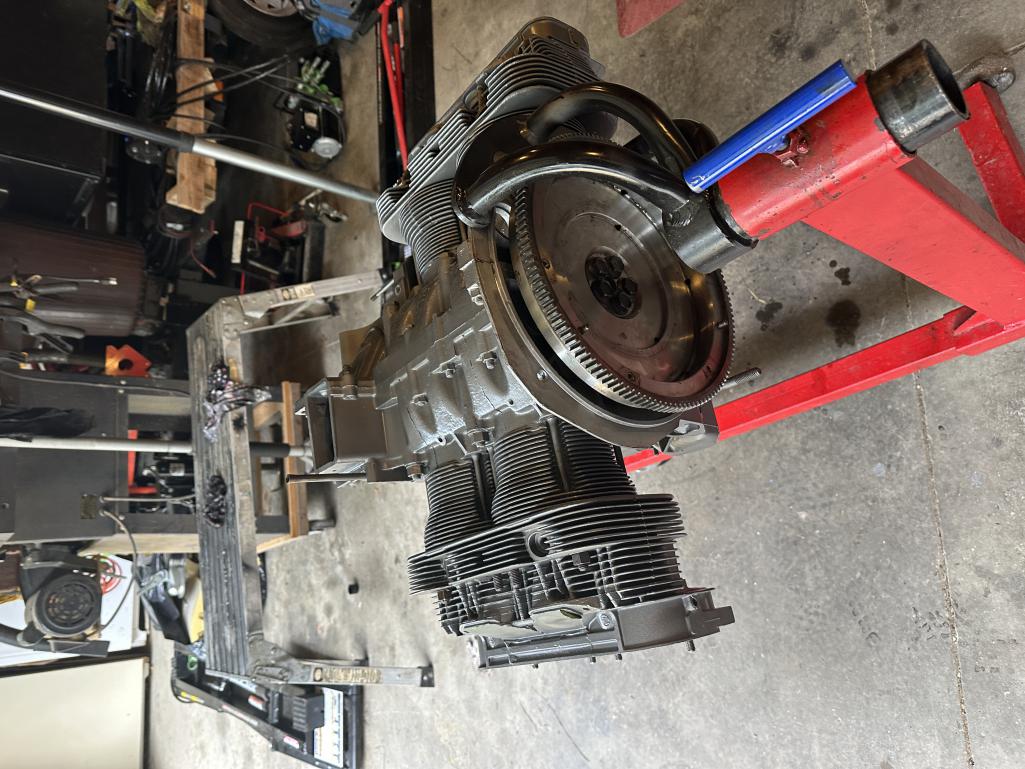
Posted by: rfinegan Jul 19 2023, 04:29 PM
another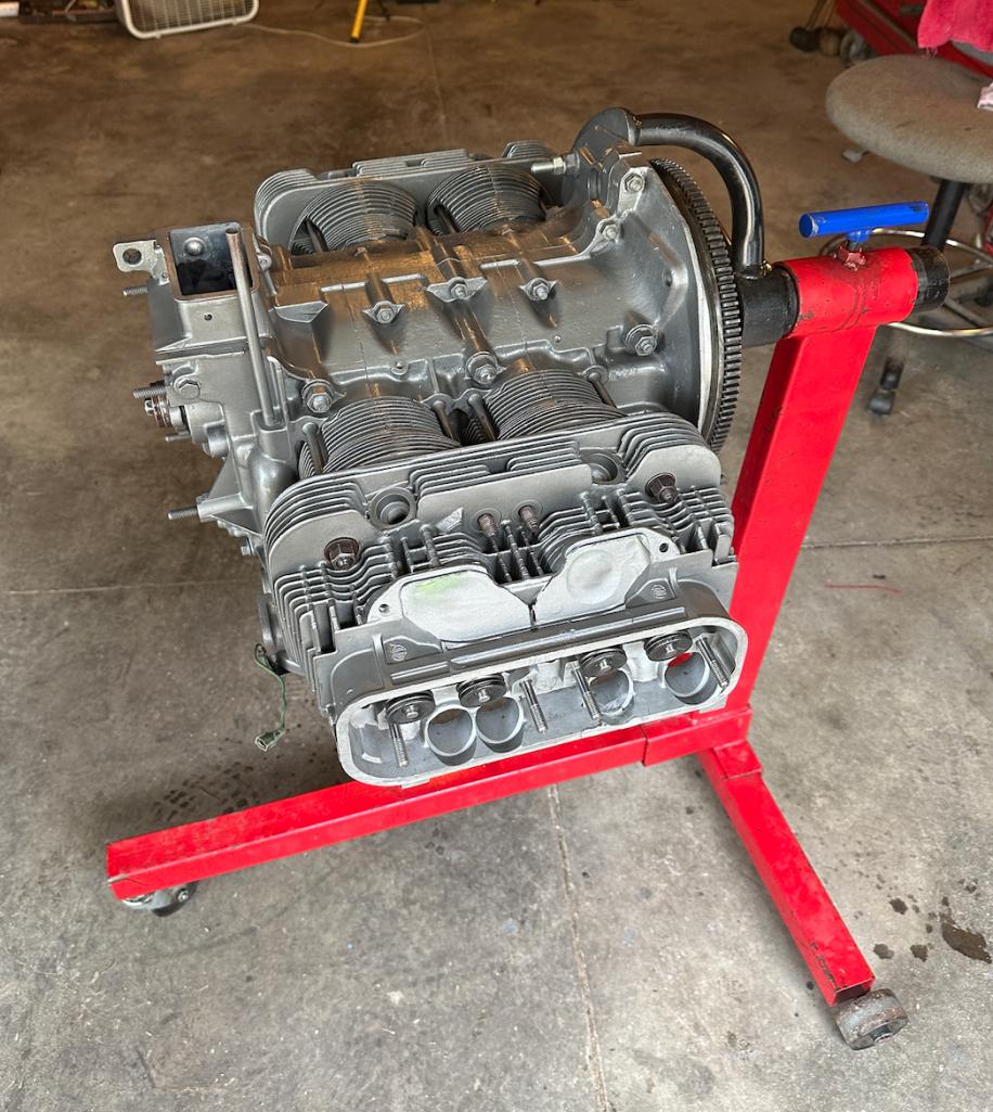
Posted by: rfinegan Jul 19 2023, 04:29 PM
one more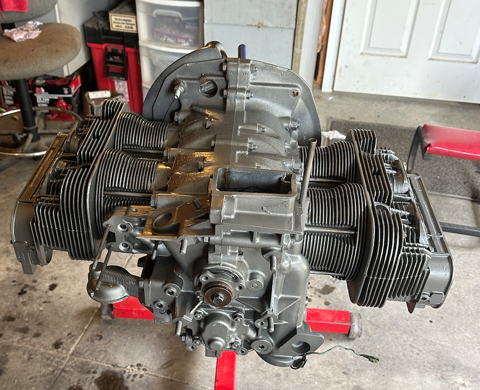
Posted by: BeatNavy Jul 19 2023, 05:14 PM
Looking really good, Robert! 
Posted by: rfinegan Jul 20 2023, 08:33 AM
Thanks Rob, Thanks for positive feed back, it is greatly apreciated.
-Robert
Looking really good, Robert!
Posted by: r_towle Jul 20 2023, 07:58 PM
Thank you for doing such a great job documenting best practices.
Wonderful way to help the rest of us.
Posted by: r_towle Jul 20 2023, 08:00 PM
TLDR,
Did you use that paint on everything?
Cool.
I request a 1/2 year update on the paint please.
Posted by: rfinegan Jul 21 2023, 05:35 AM
TLDR,
Did you use that paint on everything?
I started with the heads or the benefits of the thermal dispersion transfer, then coated the cylinders for the same benefit. The last 1/3 of the sampler from Cerakote went on the case. I did the fins on the case bottom and the rest was for appearance. It should 2 tone nice with Satin Black tins.
Cool.
I request a 1/2 year update on the paint please.
If my track recorder stays intact, it should look EXACTLY link the pics I posted above...

All kidding aside, Ill post some 6 month / 1 year pics as needed
Posted by: Cairo94507 Jul 21 2023, 06:18 AM

Posted by: rfinegan Jul 21 2023, 07:10 AM
plan for the weekend...
1)Home made Jet Doctors for IDF 44
2)Torque heads and head tins
3)Paint Push rod tubes satin Black and install lifters
4)Valve train and valve lash/covers
5)Time permitting..stub pipe installation
Continue R/D: pressurized engine priming tool/system
...lots more to come 
Posted by: rfinegan Jul 23 2023, 07:30 AM
Darn, the engine yoke got me again. its touching the # 3 cylinder. I need to pull it off again and make a slight grinder modification to the mount so it now longer touches and I can torque the head.
However i did make good progress and I have another day to get back on track... I get a pic later to show how I did this.
until then..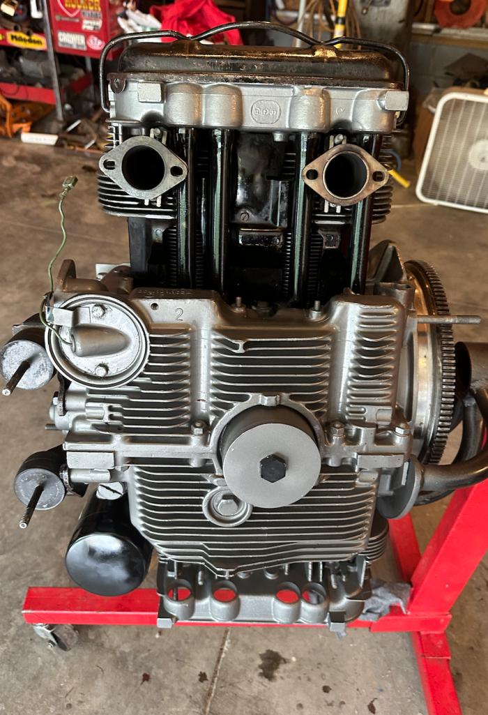
Posted by: rfinegan Jul 23 2023, 11:11 AM
DIY: Jet Doctor for idle jets or just by them from CB
I picked up some 3mm or 1/8 brass tubing from the hobby store and I did some calculations of how high to make them.. it turns you the main jet stack on my carbs are 1.950 from the bottom of the top plate..( I guess 2 inch would have been fine) but mine are he SAME height as the main stacks. IF its good enough for Weber it should work fine for the Doctor...
MY old Italian Webers had short stacks even with the top plate..I need to change the too, I guess?
1) I cut 4 piece of tubing to the correct length (1.950 inch)
2) I flared the end of the base wit ha automatic center punch to gain a snug fit in the top of the carb vent hole
3) Add some 515 gasket sealer to the hole
4) Tap and set the brass tube it to top plate till flush on the bottom of the casting
5) Repeat for the there 3 vent holes
All that is left is a few holes in the gasket and to drill 4 holes into you air cleaner base
-Cheers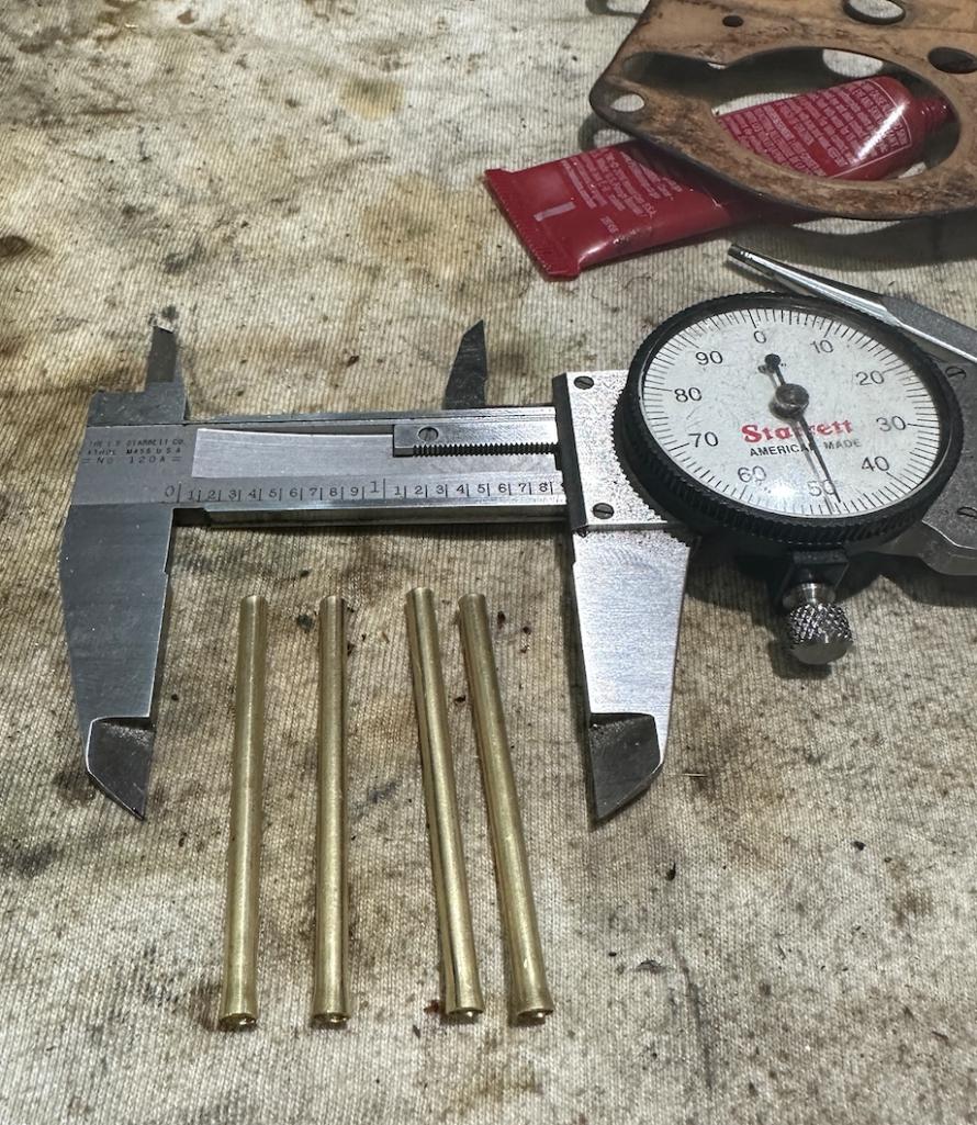
https://www.youtube.com/watch?v=boURpJiAvZk
Posted by: rfinegan Jul 23 2023, 02:30 PM
oil primer in progress...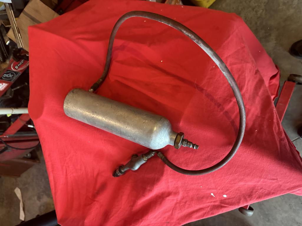
Posted by: rfinegan Jul 23 2023, 02:34 PM
engine update..stubs and tins next...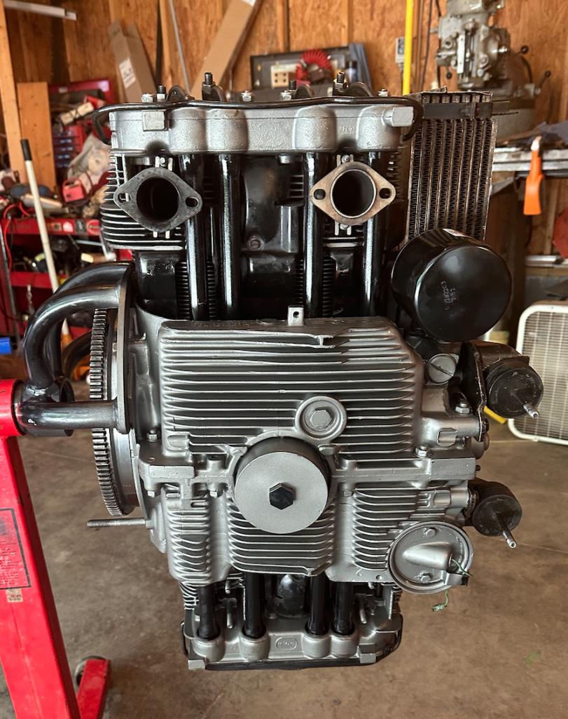
Posted by: rfinegan Jul 23 2023, 02:36 PM
engine yoke mod...#3 cylinder 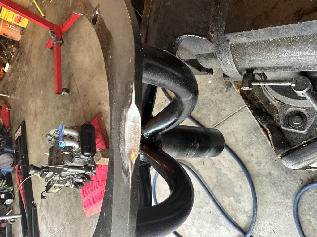
Posted by: rfinegan Jul 23 2023, 03:25 PM
cylinders hitting the the yoke frame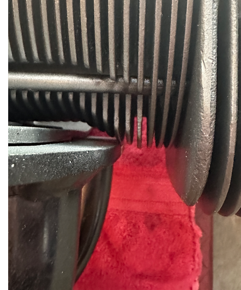
Posted by: rfinegan Jul 24 2023, 04:24 PM
Today I installer the blower housing, blower front tins alternator, belt left tin, intake...
Wanting for a Distributor drive spring before installing the right tin (tues)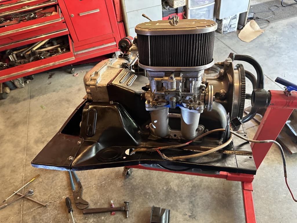
Posted by: rfinegan Jul 24 2023, 04:27 PM
another pic of the bottom
Posted by: rfinegan Jul 24 2023, 04:29 PM
Installed and torqued Clutch, Pressure plate and front Blower with blue loc tight and Alternator a with belt with front tins
Posted by: rfinegan Jul 28 2023, 05:48 PM
Today I recondition push rod tubs to remove dents and reduce diameter for clears to stub pipes
tightest clearance is #1 and #4 exhaust to stub and then 2/3 to exhaust
https://www.youtube.com/watch?v=xx6OP91X9rU
Posted by: rfinegan Jul 28 2023, 05:52 PM
added right tins and distributor
Posted by: porschetub Jul 28 2023, 08:32 PM
another pic of the bottom
looking great,thermostat and cable fitted and adjusted...hope so .
Is that and oil pre-prime system you have made ?,good idea for a first start if so.
Not too far away,good luck.
Posted by: rfinegan Jul 29 2023, 06:38 AM
I may have to try to fit an aftermarket thermostat. The header is too close for the stock on to fit. I hate the new one fails in the on position though!
Yeah getting close. about time to remove the OE engine and test the oil prime and final valve lash.
Posted by: barefoot Jul 29 2023, 06:54 AM
added right tins and distributor
Make sure you put a grommet in that hole that the alternator harness passes thru !!
Posted by: rfinegan Jul 31 2023, 05:45 AM
Good eye. Not wanting to pull the alternator/cover I have been putting this off. I decided now with your comment, to pull the terminals our of the connector and install a seal/bushing. It was not as painful as it sounds with a terminal too. Seal from Hot air and no chances of cutting or grounding my charging system.
This week starts the removal of the OE and trans. wit the Lift plate from Tangerine and fast jacks this will go quick. Done wit the test runs of my make shift engine oil primming system. With a regulator I can control the oil pressure and feed rate,. Negative: If I run the tool empty I get oil foam and air. SO small batches of prime 30 weight break in oil.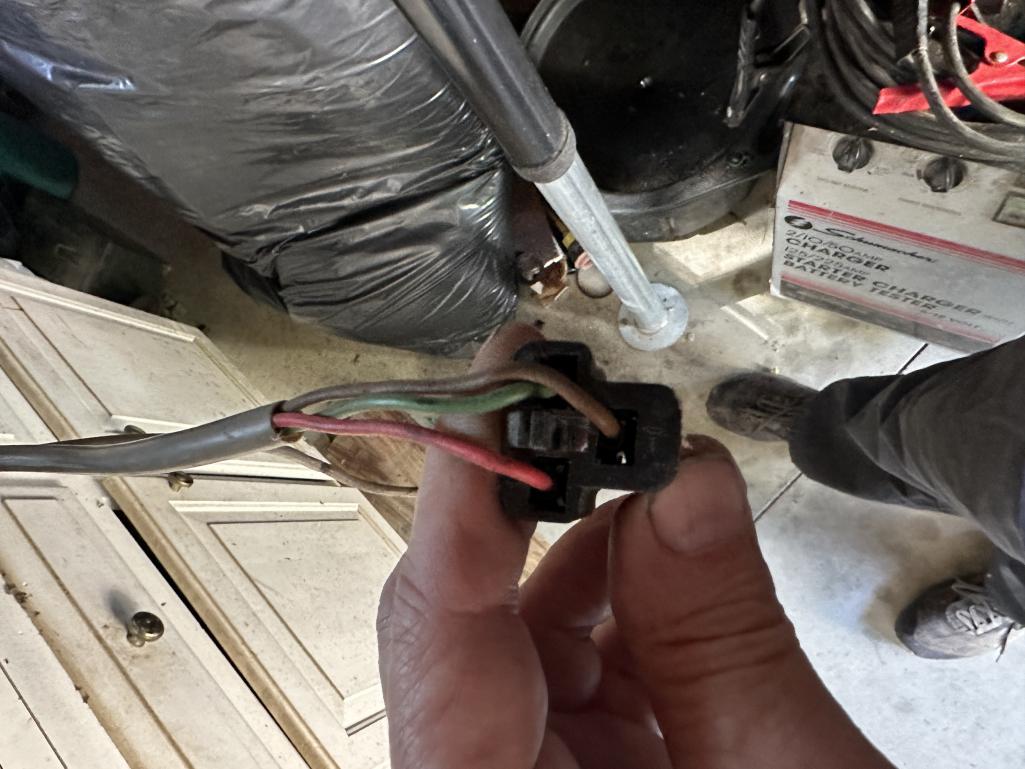
Posted by: rfinegan Aug 6 2023, 01:53 PM
Add a PMO fuel regulator (purchased in the classified here) I made a mount to the case and insulated with silicone 1/8 washers (think GM HEI button) so heat should not be much more that engine compartment ambient temps. COOL recirculating fuel! Woo hoo. SS lines to the carbs carbs and once I'm up and running will look at the Tangerine SS tunnel lines
Waiting on some 6an to 8mm fuel parts..later today
Cheers
Posted by: rfinegan Aug 6 2023, 04:23 PM
install pics..all done under the car.
including Wide band O2 and tangerine Evo muffler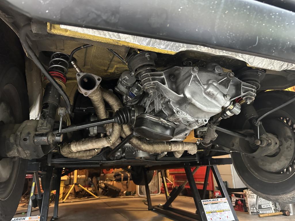
Posted by: rfinegan Aug 6 2023, 04:26 PM
another view of the Tangerine clutch mount Gen 1
no more melted cables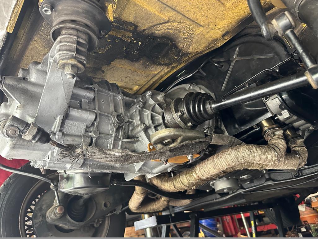
Posted by: rfinegan Aug 13 2023, 09:30 AM
Lets see how I did...
I add 5 gals of 93 octane to the tank after draining it with the stock fuel pump. this worked great wit the ground wire on the relay to run the pump when the key is one.(carbs)
Topped of the oil to full 4 qt with tuna can
Key on and checked new plumbing for NO leaks and 3 psi
SO FAR SO GOOD
Lets see if it will light off
2 pumps on the accelerator to prime pumps and got shots of fuel
KEY on and Contact....crank..crank crank...no fire
again Crank crank crank crank..no fire
pump pump crank crank crank...she is not going to go!
A quick check I found NO SPARK for my Malory
Posted by: rfinegan Aug 13 2023, 10:00 AM
SO...
I think I spiked the module doing power balance test by pulling plug wires last time it was running.
I had a no start and then it cooled and ran again..no nothing
I hooked up a 009 points distributor and a ground wire...
Gave it a spin...and ZAP, ZAP, ZAP!
Pulled the Mallory and borrowed the 123 from the Djet
Dropped it in without changing the last clamp position (ran at that setting)added the power connections and plug wires etc..
Pull the coil wire and add the stark tester
Key on"Crank crank crank = ZAP ZAP ZAP
HERE WE GO AGAIN:
2 squirts on the accelerator
Crank, cra.... VAROOM!
up to 2,000 PRM and synced the low Slave carb.... 15 Cam burn just to keep the oil pumping
60 psi
running good for 5 mins
set base timing to 10 degrees and continued the BURN for total of 15 min
Idle at 1000 and oil at 20 psi (HOT) well pretty warm
AFR 12.1 at 2K rpm may be a little rich but Looking good
Head temp at 300-340
Will tune a little more Sunday and swap out the start up oil and reset the valve lash to about .001
HERE is the proof: I did set the valve lash a little loose @ .003 so a little noisy
https://www.youtube.com/watch?v=yBEDdvhwzNU
Posted by: BeatNavy Aug 13 2023, 11:15 AM
Nice job, Robert!
Posted by: rjames Aug 13 2023, 02:27 PM
Excellent!!

Posted by: Cairo94507 Aug 13 2023, 03:33 PM
Congratulations! She sounds good.
Posted by: technicalninja Aug 13 2023, 03:55 PM
Sounds healthy!
Pretty balanced for a first start as well.
I'm a huge believer in running it under load (driving) for the first couple of hours.
Medium acceleration but using compression braking whenever possible.
Trying to achieve the highest manifold vacuum I can (engine decel).
I'd want to drive it this afternoon!
I'm happy for you and a bit envious...
My 2055 is a few months away.
You might need those smaller idle jets you have!
For no load 2K I'd want to hit north of 13.5 and south of 14.5
Posted by: rfinegan Aug 16 2023, 10:45 AM
I add a new Malory Module to my ignition system Hi fire and I have to say ...AWESOME
Dropped it right in at my OLD setting. One tap on the accelerator COLD START...Vroooooom
NO long crank or stumble. Great idle too.
Getting Better...
YES I will get the base timing set (10-12*)and limit the advance to a bout 16 degrees shooting for the DESIRED 28 total
It should be cool this weekend. 75 in the morning, so I l drive around on the idle Circuit and gets som Wide band numbers
Posted by: rfinegan Aug 16 2023, 10:47 AM
30 min or so run time so I better get some Fresh oil in it too...LUCUS 30 weight break in oil
Posted by: technicalninja Aug 16 2023, 03:28 PM
On a first run in like you just did I clean the piss out of my drain pan, drain oil into it.
Let it sit for hours, poor the top 95% off and "pan for gold" with the remains.
Shine a flashlight through it....
Any bad glitter and I'm pulling it back out...
It's so much cheaper to fix if you catch badness early.
I wouldn't do an oil analysis until after I had 10K on the new motor.
Posted by: rfinegan Aug 22 2023, 04:10 PM
Fresh oil (lucus 30w break in oil) and now hit the 100 mile mark.
I am waiting now on the Redline jet-pac for mains and air correction jets. It will be here for the weekend and a few jets from Cb that are not in the kit.
Head temps are under control (WOOHOO!)stable just under 350*f. It only breaks the 350 mark on spirted pulls and come right back down. Cruise is 325 -340*f
DID I say is 95-98 degrees here in NC wi h HIGH humidity
I will share the carb jet specs once I get the lean hole tuned out.
the Innovate LM1 is working fine. but NOT the Data Logging
Any one have the OLD Innovate Logworks 1 or 2 cd? The Log works 3 Crash on use with the Download of the log files
data logging would make this thing AWESOME
NOTE: Did any one tell you the thinner 30W oil will cool better than the thick 20W50?
Posted by: Geezer914 Aug 22 2023, 04:56 PM
I am running head temps around 230 on a hot day in NJ. Oil pressure is 78 lbs at start up and 38lbs at 3000 rpm hot. Running biral cylinders and Driven 15w50 oil. 30w may cool better, but what about oil pressure?
Posted by: rfinegan Aug 22 2023, 06:28 PM
for those not familiar with CHT ..this from Raby QA
What is a normal temperature range for a Type IV engine?
Generally head temps are desirable below 365°F. I like heads to run 265°F-365°F as a norm. 375°F -395°F is getting warm, with 405°F being too hot for any sustained period of time. Oil temps should run 180°F-220°F, as an optimum. 225°F-235°F is warm and 235°F+ is hot and should
Posted by: yeahmag Aug 23 2023, 12:03 AM
WRT the Mallory module. I'd suggest not only adding the Mallory Circuit Guard, but also a ballast resistor to drop the voltage to the module. It was only after I had both that I stopped losing modules.
Posted by: Geezer914 Aug 23 2023, 05:07 AM
I second the Mallory circuit guard and ballast resistor.
Posted by: VaccaRabite Aug 23 2023, 07:18 AM
I am running head temps around 230 on a hot day in NJ. Oil pressure is 78 lbs at start up and 38lbs at 3000 rpm hot. Running biral cylinders and Driven 15w50 oil. 30w may cool better, but what about oil pressure?
Head temps or oil temps? Those would be cold for head temps. I usually don't consider my engine warmed up till the heads are reading 270, and operating temps are 280-360.
For my engines - 350 is pulling a hill at speed on the freeway on a nice day. 360 is doing that on a warm day. 370 is doing that at close to 90mph with temps in the 90s and the hill is long.
Zach
Posted by: rfinegan Aug 23 2023, 07:28 AM
This about where I am at too for CHT
My oil is 210 to 220 about straight up and down
I am running head temps around 230 on a hot day in NJ. Oil pressure is 78 lbs at start up and 38lbs at 3000 rpm hot. Running biral cylinders and Driven 15w50 oil. 30w may cool better, but what about oil pressure?
Head temps or oil temps? Those would be cold for head temps. I usually don't consider my engine warmed up till the heads are reading 270, and operating temps are 280-360.
For my engines - 350 is pulling a hill at speed on the freeway on a nice day. 360 is doing that on a warm day. 370 is doing that at close to 90mph with temps in the 90s and the hill is long.
Zach
Posted by: rfinegan Aug 23 2023, 07:29 AM
I am running head temps around 230 on a hot day in NJ. Oil pressure is 78 lbs at start up and 38lbs at 3000 rpm hot. Running biral cylinders and Driven 15w50 oil. 30w may cool better, but what about oil pressure?
This sounds great for OIL temps. Perfect
Posted by: rfinegan Aug 23 2023, 07:34 AM
WRT the Mallory module. I'd suggest not only adding the Mallory Circuit Guard, but also a ballast resistor to drop the voltage to the module. It was only after I had both that I stopped losing modules.
Are you running a CD ignition like MSD or HiFIre?
The unilite is only triggering an electronic circuit and is low voltage and low amp. I cooked mine by pulling Ignition wires and hit it with 40K volts. Spike perfection is always a good thing but that is another 90 bucks? I think a spare module can had for that... will see how this one goes and decide if I take out insurance for the Mallory Circuit Guard
Ballast is not needed with the Hifire, or that’s what there paper work shows
Posted by: rfinegan Aug 29 2023, 05:23 PM
Tuning the 40 IDF 32 vents. Still running a bit rich but my temps numbers are very good at 335-365 and peaks to about 375
I did have to drill some jets to get in between numbers
Base line timing @11* and all in at 3000 for total 29*
accelerator pump rod at 6.5 mm
idle jets 57
f11
main jets 137
corrections 210
wot is still 12.2 to 12.6
next try will be:
135 mains and 190-200 air correction
rich hole air 3200 to 3400 still in transition circuit and mains coming on
She will pull STONG if you let her...
Posted by: r_towle Aug 29 2023, 05:32 PM
Lm1 not logging?
Can you describe the hardware?
Is there a plug? Are you using a laptop?
Rich
Posted by: yeahmag Aug 29 2023, 06:07 PM
WRT the Mallory module. I'd suggest not only adding the Mallory Circuit Guard, but also a ballast resistor to drop the voltage to the module. It was only after I had both that I stopped losing modules.
Are you running a CD ignition like MSD or HiFIre?
The unilite is only triggering an electronic circuit and is low voltage and low amp. I cooked mine by pulling Ignition wires and hit it with 40K volts. Spike perfection is always a good thing but that is another 90 bucks? I think a spare module can had for that... will see how this one goes and decide if I take out insurance for the Mallory Circuit Guard
Ballast is not needed with the Hifire, or that’s what there paper work shows
I run a Mallory 6AL with the Mallory Unilite distributor on my car.
Posted by: rfinegan Aug 29 2023, 06:08 PM
Seems to be a known issue with the logworks 3 application
There is a function to download the saved log files from the old lm1 recorder/display
This worked on the older logworks 1 and logworks 2 running xp or vista
the newer software crash on download of the log files and innovate did not fix in the newer version logworks 3
I can get an old PC but not finding the install cd / download for the older log woks app/interface
Posted by: rfinegan Aug 31 2023, 10:30 AM
While waiting on a 57 idle jet, I pulled a plug to check how its burning...
...it has a nice tan!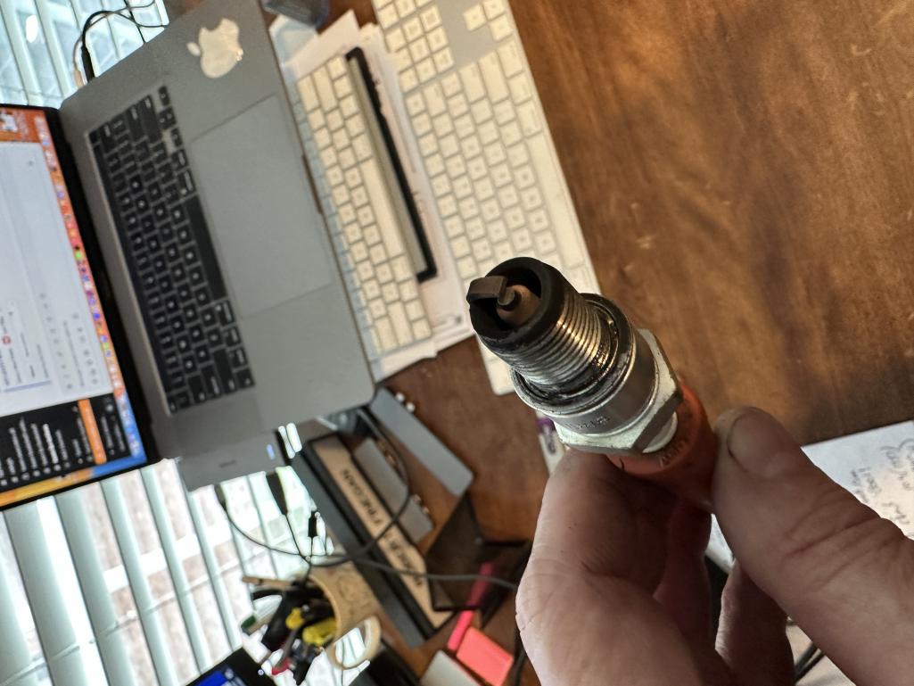
Posted by: rhodyguy Aug 31 2023, 01:14 PM
What are you Mallory guys using for spark plug wires?
Posted by: rfinegan Sep 1 2023, 07:19 AM
I have the red 8mm Malory plug wires, but they will attach to the VW OE distributor cap too
What are you Mallory guys using for spark plug wires?
Posted by: rfinegan Sep 1 2023, 07:34 AM
Today I installed an Older version of the Logworks3 software on a VM for XP (vm ware studio.) The old version was found in Way back machine for 2012 and is WORKING. It DID Not work on Windows 10. I was able to get 21 logs from the device and will clear the old (PO) logs and take my first recording of the AFR and with a bit of luck an RPM cannel too. I had to rig my inductive pick up to a 3.5 mm Audio jack input to the PRM adapter and analog adapter cable
Progress on the data logger and 57 idle jets are on the way. Hand drilled .60 were too BIG and .55 had a big lean hole in the transition at 3-4 k rpm Pop. Pop Pop and 16:1. I open my idle mixture screws another 1/2 turn and the Pops are gone. running pretty good and hands off the tip in pretty good.
Mains are reading 12:5 t o 12.8(1.30) for WOT and leaning out a little more as redline approaches . Trying real hard NOT to see REDLINE. But pulling a quite bit Higher and longer Into the upper rpm ranges 6K +. :-).Not just making more noise, but still pulling harder as it revs....(on the BUTT DYNO). Double valves springs will handle this No Problem
200 + miles on break in and leaks have been found and fixes
FWIW: I had to clean my speedo head of grease from the cable lube years back that made its way up to the head and the Odometer gear was slipping. ALL set and working very well and smooth again. That junked things up pretty bad and the needle/pointer was not returning any more
Posted by: rfinegan Sep 1 2023, 11:12 AM
My first log....The last downward slope is the mains coming in at 35- 4500 rpm and look good at 13.2:1 and richening slightly (1.30)
I think I see the lean pop pop pop at 2-5 sec. (55 idle jets)
Here is an odd observation
While warming up the first light throttle up into the transitions feels smooth and no pops. try it again in a few seconds or another gear and is lean
Some times the ratios feel look good some times they are lean
I am going to have a helper watch my fuel pressure gauge on some next recordings
I did read somewhere that the fuel enricher (choke) gave some users problems rich or lean (not sure) that are not hooked up but the valves are in place.. I have seen dummy valves tap took off the ports (X4) with no holes.. 15-17 bucks each
I have richened the mains to overlap over the transition circuit and felt a little sluggish rich but not great numbers on the mains and WOT. But no lean hole or pop pop pop. I feel I’m on track with the correct 130 to 135 mains and richening the ideas to .57.
.60 Idle jet was very rich and 55 too lean
Fun to see how thy work
MORE LOGGING FUN TO COME
FIRST imported graph after a little smoothing
My RPM was off but working so I need to rewire my adapter on the 3.5 mm audio jack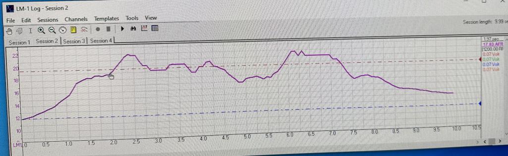
Posted by: rfinegan Sep 1 2023, 01:30 PM
I did get the RPM input working for the inductive 3.5 jack
Set the range for 0-1 volt and the rpm seem to be spot on now
woo hooo
another small win
Posted by: rfinegan Sep 4 2023, 08:10 AM
FWIW:
It was 2 years ago today I was driving the gen 2 2056 for it short lived 50 miles....
Posted by: Cairo94507 Sep 4 2023, 09:25 AM
Good job getting this sorted Robert.
Posted by: technicalninja Sep 4 2023, 10:06 AM
My first log....The last downward slope is the mains coming in at 35- 4500 rpm and look good at 13.2:1 and richening slightly (1.30)
I think I see the lean pop pop pop at 2-5 sec. (55 idle jets)
Here is an odd observation
While warming up the first light throttle up into the transitions feels smooth and no pops. try it again in a few seconds or another gear and is lean
Some times the ratios feel look good some times they are lean
I am going to have a helper watch my fuel pressure gauge on some next recordings
I did read somewhere that the fuel enricher (choke) gave some users problems rich or lean (not sure) that are not hooked up but the valves are in place.. I have seen dummy valves tap took off the ports (X4) with no holes.. 15-17 bucks each
I have richened the mains to overlap over the transition circuit and felt a little sluggish rich but not great numbers on the mains and WOT. But no lean hole or pop pop pop. I feel I’m on track with the correct 130 to 135 mains and richening the ideas to .57.
.60 Idle jet was very rich and 55 too lean
Fun to see how thy work
MORE LOGGING FUN TO COME
FIRST imported graph after a little smoothing
My RPM was off but working so I need to rewire my adapter on the 3.5 mm audio jack
Is the left margin AFR?
If so most of that graph looks dangerously lean IMO. Anything over 16 is "lean burn" In my book and above 20 should be avoided at all costs on everything.
18:1 appears to be the limit on a water-pumper set up for lean burn on gasoline.
During acceleration I want to be as lean as cylinder head temps can take it but below 13.5. Maybe richer on an air-cooled.
Only way to consistently run above 15:1 on gasoline is to have an engine designed for lean burn and a seriously active self-adjusting FI system with knock sensors.
Modern OBD2 systems work fine with lean burn but I'm not aware of a lean burn set up on an air-cooled motor.
Maybe the very last air-cooled 911s had it. They also had twin plugs and a bunch of modern technology that the T4 did not.
I would expect that would run HOT and tend to detonate. It would be very sensitive to timing adjustments.
The number on the right margin for AFR is what I believe the average for the graph and shows 17.83.
IMO, long term those AFR readings are the DEATH of new motor.
If that left margin is not AFR then the above may not apply.
I'd also check and re-calibrate the wideband as your plug does NOT look 17.8/1.
Plug looks great, maybe a tiny bit rich, IMO.
An 18:1 plug would look "glowing" white and have little white deposits on the ground strap.
Edit: Can someone tell me why the image didn't post over with the quote. I wish it had as it makes more sense if the image was with the quote.
Posted by: rfinegan Sep 4 2023, 05:03 PM
Rich plug soot is due to idle screw out to give more air fuel to richen the lean hole at top of transition
The tan is the wot and the 13.2:1 as its leaning out a the end with the 130 mains with f11 emulsion tubes
Agreed the 55 idle jets are way too lean
I will post the graph of the new .57 idles some time tomorrow
Posted by: rfinegan Sep 4 2023, 05:30 PM
The right margin is the key and the curser value under the mouse
Posted by: technicalninja Sep 4 2023, 05:50 PM
The last two posts don't really make sense to me regarding the graph.
The left margin appears to be showing LM1 (sensor) from below 10 afr to above 22 afr on the vertical axis.
The purple line appears to start at 12/1 and rapidly rise to 22/1 never dropping below 17/1 until 8.25 occurs on the horizontal axis.
I'm guessing the horizontal axis is time in seconds.
Am I correct in the way this graph is set up?
I guess I'm slow as I have no idea what "The right margin is the key and the curser value under the mouse" means.
Once again, I didn't get the graph. It showed up on "preview post" just fine.
Guess I am slow...
Posted by: rfinegan Sep 5 2023, 04:08 PM
new jets for idle .57 came in today..still too rich so back to the .55 and a data log snapshot recording
40 pdf
32 vents
55 idles
210 air
1.400 mains
29* timing at 3000
next move it to 220 air
single pull to 3600 rpm
Note the dip rich at the end is the main jets 140(rich) coming in.This was to show where the lean hole is and will continue to add air correction till the lean spike is gone...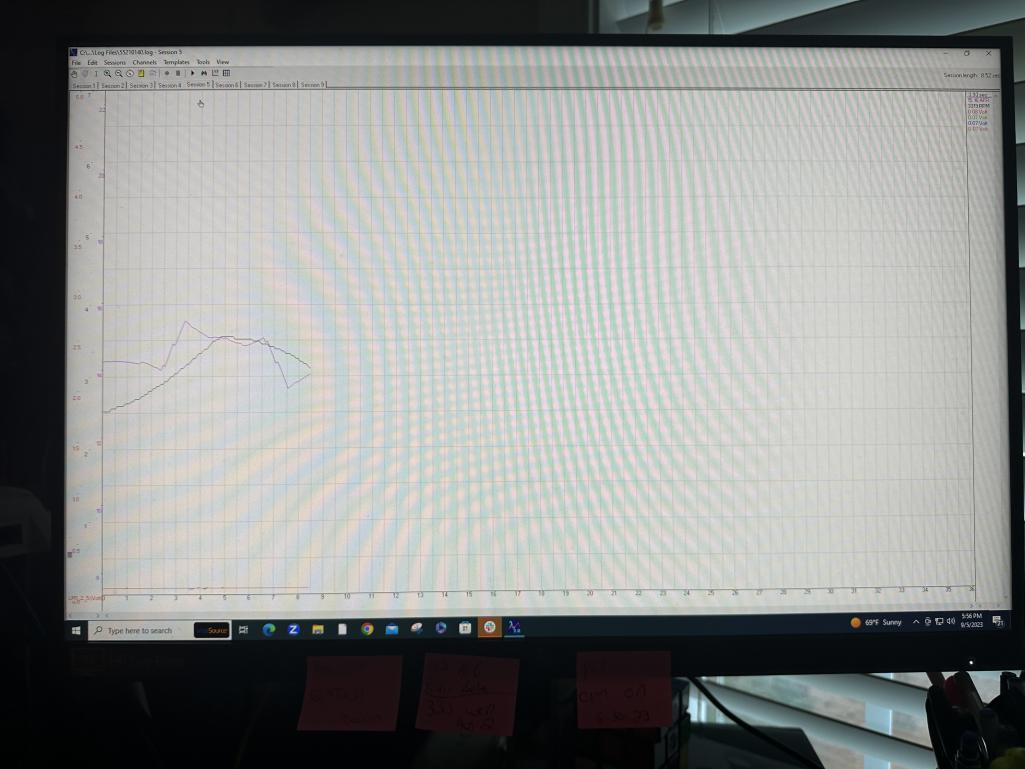
Posted by: emerygt350 Sep 5 2023, 05:21 PM
Too rich?
Are these WOT pulls?
Are these pulls? I mean are these under load?
Posted by: rfinegan Sep 6 2023, 05:43 AM
all data logs are while driving
Saving WOT for last but I am feeling the main pull hard at 3500 rpm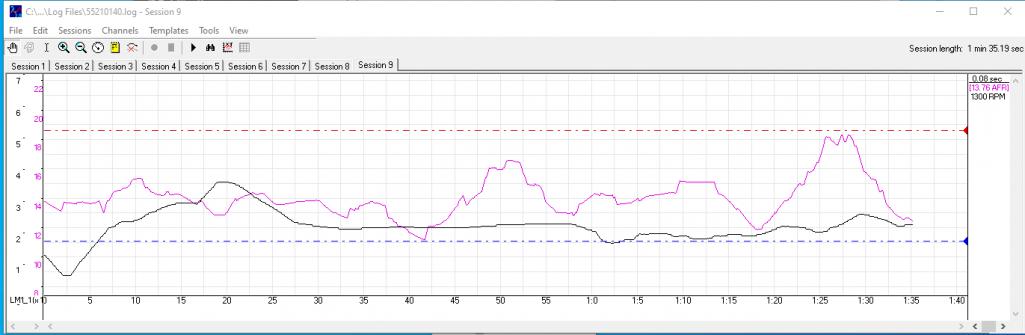
Posted by: rfinegan Sep 6 2023, 09:14 AM
I will add a degree or 2 (+-) now that it is no longer running rich and see how the temps and performance base line again...
Posted by: rfinegan Sep 6 2023, 12:21 PM
more fun with Logworks 3
https://www.youtube.com/watch?v=_2f9yGM7hhY
https://youtu.be/_2f9yGM7hhY
Posted by: Shivers Sep 6 2023, 01:45 PM
Add a VDO HEAD TEMP thermocouple under the #3 spark plug. Milled a small hole for the wires and crimp.
That is pretty cool sir
Posted by: emerygt350 Sep 6 2023, 05:31 PM
Is the blue line the old and the dark line the new? I think you might be reversing the terms... It was running lean, if I am reading that correctly. Now it looks really nice, and rich enough not to blow your engine up
Posted by: VaccaRabite Sep 6 2023, 07:26 PM
I'm still sitting here trying to figure out what is on the graphs.
On the last graph with the purple and Black lines...
Is Purple AFR and Black RPM?
Or is purple and old run and black a new run?
You need to have a line on the chart that shows RPM somewhere. It will help a LOT with tuning.
Zach
Posted by: rfinegan Sep 7 2023, 05:31 AM
Is Purple AFR and Black RPM
0-7000 rpm Black
0-22 afr Purple
all the runs or recording sessions are in its own tab
This shows a gradual pull ”driving” from first gear and 1000 rpm to about 3500 rpm for a pull on the main jets for about 5 sec 1/2 t o 3/4 throttle pedal .
I thinks this is followed by a shift and cruse in second for a time at about 2500 rpm
Followed by a shift in 3rd at 2000 rpm cruise ( 1 min mark) and gently drive away...
( I think, I need take better notes..it may be just a single pull and a gradual cool down and no shifts just a first gear pull?
emerygt350
yeah its looking pretty good
Posted by: rfinegan Sep 7 2023, 05:43 AM
I have been playing with a PMO fuel regulator. The gauge says 3 psi and stays steady, but the feel you get is it fine driving and the hand off from transition to main is smooth and the next time time I get into it it seconds later feels like there is not enough fuel. if I can not get this sorted, I will put the CB/Tangerine 3 psi pump back on with no fuel return
Posted by: rfinegan Sep 7 2023, 05:58 AM
no work last night for bowling/drinking beer.. High game of 223 and 605 scratch series (WOOHOO)
Thinking, reviewing data logs and clearing my head...rain this week end, I may run a quick errand and get some more test data
Posted by: rfinegan Sep 7 2023, 06:04 AM
The dash board and the graph are the same session
Posted by: rfinegan Sep 7 2023, 01:55 PM
WOT pull with 12* init and 31* total time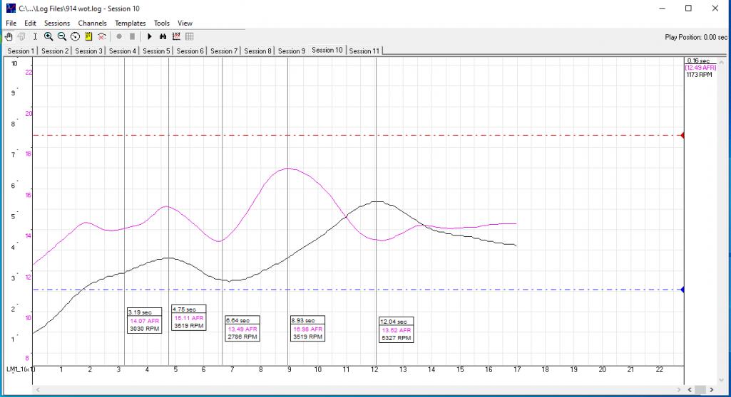
Posted by: VaccaRabite Sep 7 2023, 02:26 PM
WOT pull with 12* init and 31* total time
You look way lean in that WOT pull.
Tuning for Stoich is going to give you higher head temps. AFR of 11 or 12 when stomping on it will burn a little more fuel but will cool the heads and maybe net you a tad more power. It seems like you are maybe tuning for lean burn but I don't know if that's a great idea with carbs on an aircooled.
Zach
Posted by: emerygt350 Sep 7 2023, 03:00 PM
I would be super scared of those values, particularly down low too. Up high it can get wonky but I would be shooting for nothing ever touching even 13 during a WOT pull. Between 3 and 4k is when these engines are really building their power and you are running super lean at that point.
Only time I want to be at 14.7 is cruising under very light load.
Posted by: rfinegan Sep 7 2023, 03:53 PM
FWIW< I’m trying to get the lean spots out of there..
13.1 across the board and maybe touch 13.9 /14 on light cruise
Posted by: emerygt350 Sep 7 2023, 06:44 PM
Now that I understand the log, that is pretty cool. Good thing you got it working again. Is this Wot pull in first or 4th? Or are you shifting?
I think it might be best to keep it in a gear like 3 or 4 and go from 1k to 5k
Posted by: rfinegan Sep 8 2023, 05:28 AM
Now that I understand the log, that is pretty cool. Good thing you got it working again. Is this Wot pull in first or 4th? Or are you shifting?
I think it might be best to keep it in a gear like 3 or 4 and go from 1k to 5k
This was a first gear pull and if I recall, I had to let up at 4-6 sec as other car was impeding my smooth pull on the road
Posted by: VaccaRabite Sep 8 2023, 07:02 AM
Now that I understand the log, that is pretty cool. Good thing you got it working again. Is this Wot pull in first or 4th? Or are you shifting?
I think it might be best to keep it in a gear like 3 or 4 and go from 1k to 5k
This was a first gear pull and if I recall, I had to let up at 4-6 sec as other car was impeding my smooth pull on the road
When I am tuning I'll usually do my WOT pulls in second or third. First is a weak gear in a 901 box.
Also make sure the engine is fully warmed up before getting tune data. Especially with carbs you are going to get garbage data when everything is cold. Not saying that's what happened here - you may have been fully warmed up. But if you were not - its something to keep in mind.
Zach
Posted by: rfinegan Sep 8 2023, 07:06 AM
Zack
thanks for the tip...ill try another if the weather hold out today
Posted by: rfinegan Sep 8 2023, 10:41 AM
a little too big on the main at 1.450 and 220 air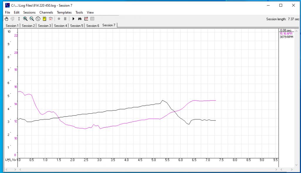
Posted by: rfinegan Sep 8 2023, 10:42 AM
another pull in 3rd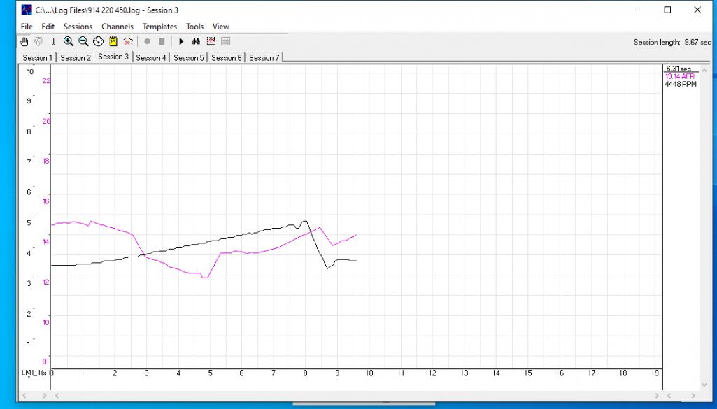
Posted by: rfinegan Sep 8 2023, 10:44 AM
11 afr is too rich for me...
Posted by: rfinegan Sep 8 2023, 11:01 AM
6k pull. This looks pretty good
Attached thumbnail(s)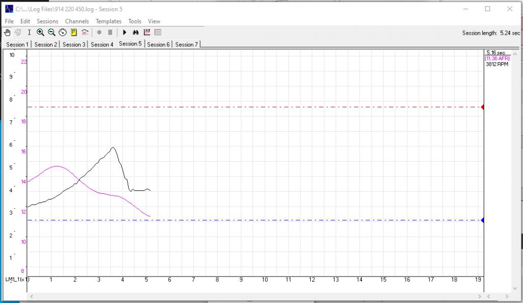
Posted by: VaccaRabite Sep 8 2023, 12:40 PM
Those look a lot better. Its better to be on the rich side then the lean side when you stomp on it.
Get a log just driving around how you usually drive the car and compare WOT to normal driving. Do a log just cruising with low load.
Zach
Posted by: emerygt350 Sep 8 2023, 07:12 PM
Yes, this looks much better and the daily driving log would be great. I would be nervous about those lean parts of 3 to 4k, that's where the fun is and often the point at which the engine is under the greatest load, I would rather be at 12-13 there. Even my water buffalo mustang keeps it around 12.5 under that kind of condition.
Powered by Invision Power Board (http://www.invisionboard.com)
© Invision Power Services (http://www.invisionpower.com)