Printable Version of Topic
Click here to view this topic in its original format
914World.com _ 914World Garage _ @StarBear L Jetronic Temp Sensor II AFM
Posted by: wonkipop Jun 5 2023, 03:12 PM
@http://www.914world.com/bbs2/index.php?showuser=10753 .
here is what i have on the Temp Sensor II inbuilt into the AFM on the 1.8 L Jetronic.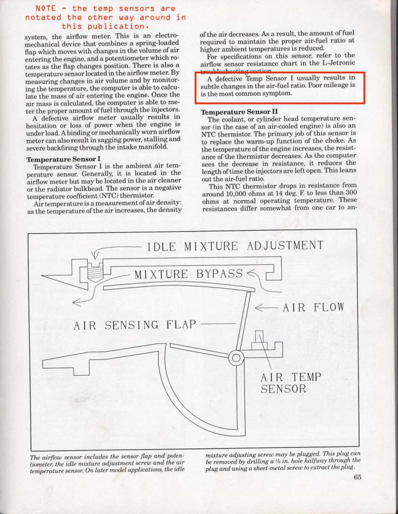
i could be wrong but i don't think there is any effective way to test the air temp sensor in the AFM on our adam/eve in the garden of eden L Jetronic system. that sensor is not wired in separately.
but maybe there is an expert here who knows.
- in relation to the problem you are having with hot days and ultra high humidity causing the idle to drop to barely running - i'm not sure the symptom fits a faulty Temp Sensor II in the AFM. others here might know better. I would not have thought a faulty sensor would cause that dramatic a result. Temp Sensor 1 (CHT) - yes. but Temp Sensor II no.
i am sure @http://www.914world.com/bbs2/index.php?showuser=26011 will pipe in with a more learned view.
I would have thought Temp Sensor 2 fault would make the car run rich.
I think that is how it would work. but again i am probably wrong.
i'd have to think about it.
most trouble shooting literature i can dig up says failure mode causes car to run richer generally. increased fuel consumption.
Posted by: StarBear Jun 5 2023, 07:50 PM
Got it! Will add to my other write up and collect some data! The game is afoot….
Posted by: MartyYeoman Jun 5 2023, 10:41 PM
![popcorn[1].gif](style_emoticons/default/popcorn[1].gif)
Posted by: ClayPerrine Jun 6 2023, 06:33 AM
Temp sensor 2 is used for gross fuel adjustments.. aka warmup. After the engine is warm and the resistance is below a certain point, the ECU, for the most part, ignores it. I had one fail on a hot engine, and I just grounded the wire to make the ECU see a low resistance signal. I was able to drive it home like that.
Temp sensor 1 is the fine tuning for the mixture based on temp. It is always on, and measuring the temp of the intake air to trim the fuel mixture.
I have not done this, as I don't see the value in it. But the temp sensor 1 was the same all the way through the AFM on the 964, and with the move in favor of a MAF sensor 993, it became a separate part. So theoretically, you could get the air temp sender for a 993 and put it in the air flow somewhere and wire it into the harness.
That being said, there are LOTS of original L-Jet AFMs out there. So there really isn't a point in reinventing the wheel.
Posted by: Rob-O Jun 6 2023, 10:14 AM
Don’t want to get off topic but isn’t the temp sensor I only on the ‘75/‘76 models (hence the 7 pin connector)?
Posted by: StarBear Jun 6 2023, 11:28 AM

Don’t want to get off topic but isn’t the temp sensor I only on the ‘75/‘76 models (hence the 7 pin connector)?
Yes, as discussed in the recent thread by Geezer914. The TempII sensor is integrated into the 74 AFM, not separate with own pin. See Haynes page 177, wiring diagram 3.
Trick will be to check/confirm if mine has an issue.
Posted by: StarBear Jun 6 2023, 12:47 PM
@http://www.914world.com/bbs2/index.php?showuser=24231
{- in relation to the problem you are having with hot days and ultra high humidity causing the idle to drop to barely running - i'm not sure the symptom fits a faulty Temp Sensor II in the AFM. others here might know better. I would not have thought a faulty sensor would cause that dramatic a result. Temp Sensor 1 (CHT) - yes. but Temp Sensor II no.}
=> That is my thought, but exploring it as don't know how sensitive it is.
{i am sure @http://www.914world.com/bbs2/index.php?showuser=8571 B will pipe in with a more learned view.}
=> Hope so!
{I would have thought Temp Sensor 2 fault would make the car run rich.}
=> Depends on fault setting (if no signal temp goes to low fault or high fault)? I might think so - less dense air would call for less fuel, unless temp sensor out, then putting in too much fuel for the density/mass of air entering. If rich, would that drop the idle down? Seems to act at a critical temp point (OK for cold, cool and mildly warm outside air/humidity, then off the cliff with high, like 80+ deg F., 80% humidity, temp/humidity).
Will start checking this out after this weekend's activities, then maybe start effort to install the NOS AFM, with adjusted CO, A/F sample port bung, etc.
Posted by: wonkipop Jun 6 2023, 04:48 PM
@http://www.914world.com/bbs2/index.php?showuser=24231
{- in relation to the problem you are having with hot days and ultra high humidity causing the idle to drop to barely running - i'm not sure the symptom fits a faulty Temp Sensor II in the AFM. others here might know better. I would not have thought a faulty sensor would cause that dramatic a result. Temp Sensor 1 (CHT) - yes. but Temp Sensor II no.}
=> That is my thought, but exploring it as don't know how sensitive it is.
{i am sure @http://www.914world.com/bbs2/index.php?showuser=8571 B will pipe in with a more learned view.}
=> Hope so!
{I would have thought Temp Sensor 2 fault would make the car run rich.}
=> Depends on fault setting (if no signal temp goes to low fault or high fault)? I might think so - less dense air would call for less fuel, unless temp sensor out, then putting in too much fuel for the density/mass of air entering. If rich, would that drop the idle down? Seems to act at a critical temp point (OK for cold, cool and mildly warm outside air/humidity, then off the cliff with high, like 80+ deg F., 80% humidity, temp/humidity).
Will start checking this out after this weekend's activities, then maybe start effort to install the NOS AFM, with adjusted CO, A/F sample port bung, etc.
i think that is all you can do. replace AFM. see what happens.
i don't believe there is any effective way to test the temp sensor on the 001 AFM.
i guess there must be data somewhere on how to thoroughly test these earlier AFM units or otherwise the rebuilders would not be able to rebuild? i imagine if you access the interior of the AFM and were able to directly tap into the two wires from the temp sensor you could do it. i forget which pin it is that the temp sensor is fed into on ours, but its signal is mixed in with one of the other pins.
interiors of AFMs are a place i do not go.

@http://www.914world.com/bbs2/index.php?showuser=26011 laughs at me about that.
i know that mike thinks the AFM on my 914 is a curiosity with the 6 pin connection.
he'd never seen one. nothing that early ever came to australia originally.
there is a guy who rebuilds AFM units. we got an AFM for a 964 fixed up by him.
i should ask him about the ease of repairing/rebuilding mine.
i'm betting he has never seen one with the 001 part no. in the flesh before.
Posted by: StarBear Jun 6 2023, 06:59 PM
As always, seems like yet again we’re “special”!
Posted by: wonkipop Jun 6 2023, 08:34 PM
Don’t want to get off topic but isn’t the temp sensor I only on the ‘75/‘76 models (hence the 7 pin connector)?
here you go @http://www.914world.com/bbs2/index.php?showuser=1419
different publications/tech manuals swap around which one to call I or II but to avoid confusion most call it II in the AFM. so i'll go back to calling it II for this. but for clarity, the one in the AFM.
74 temp sensor II in the AFM (bosch AFM 0 280 200 001)


75 temp sensor II (bosch 0 280 201 002)

its in both, in the same place, but modified design in the 75.
sticks further into airstream. altered shape of probe.
and its wired in separately in the 75.
resulting in one extra pin to make it a 7 pin. the 7th pin is for the temp sensor.
(although its not the pin at the end - its added somewhere in the middle from memory, been a while since i looked at those pin diagrams).
and likely something different going on in the ECU as well?
different ECU in the 75 from 74.
as to how its wired in and how its fixed into the AFM body in the 74s exactly i don't know in detail as i have never had mine apart. but thats the issue with the 74s. its not as easy to dig it out and replace it as a single component. i'm guessing it could be done if you had the sensor and you knew what you were doing.

Posted by: wonkipop Jun 7 2023, 04:52 AM
As always, seems like yet again we’re “special”!
oh yeah
real special
truly.
you tell me how many cars you have owned with an origin point part #.
make no mistake the L jet 914s are right at the 0,0,0 point on the XYZ axis of it all.
mike flipped out when he was looking at the part no. on the air flow meter on my 914.
made his mechanic's mind day. he had actually sighted a numero uno part in his career.
and i get it.
Posted by: ClayPerrine Jun 7 2023, 05:38 AM
In an 74 L-Jet air flow meter, the temp sensor shares a ground return with the vane air meter. In 75, they separated the return signals.
Pin #8 at the ECU is the shared ground. Pin #9 at the ECU is the Air temp sensor signal. The wiring diagram does not have the pinout numbers on the air flow meter side.
That's the difference electrically.
Posted by: Van B Jun 7 2023, 04:42 PM
Sorry for being out of pocket guys…
Temp just to clarify terms and locations, Temp II is your CHT sensor. Temp I is in your AFM:
If you had a fancy porsche tester from ages ago, you would be looking for 300ohms:
Otherwise, we have this option to test the AFM:
The only other temp sensor on a 74 L-Jet is the TTS.
Posted by: wonkipop Jun 9 2023, 12:44 AM
@http://www.914world.com/bbs2/index.php?showuser=26011
those middle two tables you posted are for the D Jet system.
where you use those ye olde EFAW testers.
but not for using with L jet. don't think you can even hook an EFAW up to an L Jet.
i've searched and searched for any kind of test you can do on our 74 AFMs to test temp sensor I and i can't find one. reason being as clay perrine mentions.
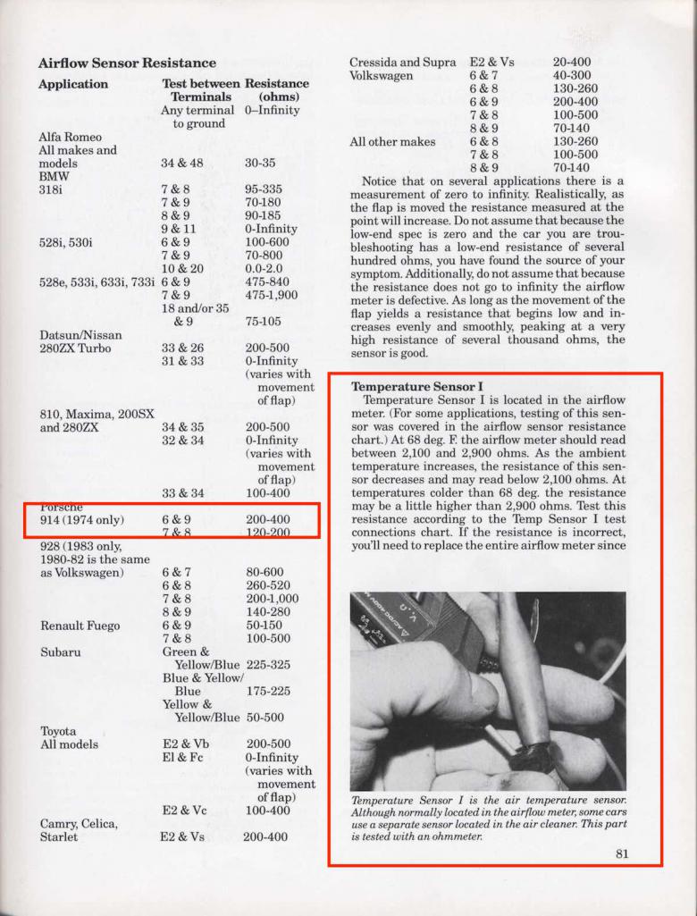
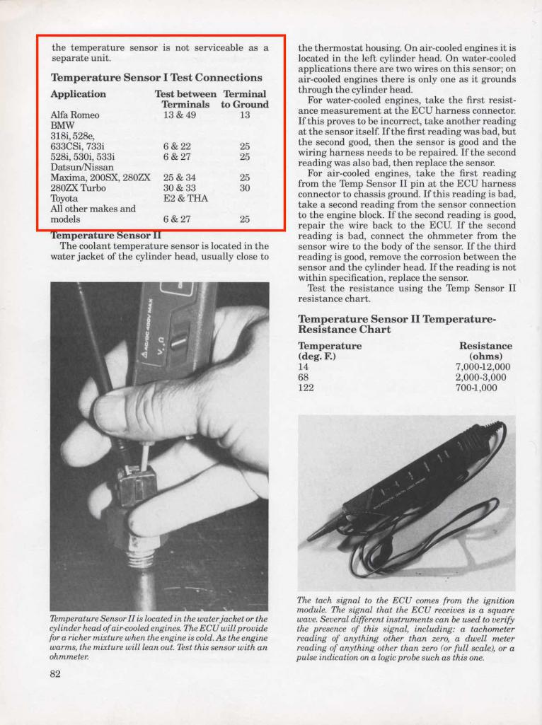
you can do a specific test on the 75 AFM. you test between pin 6 and 27.
27 being the extra pin that is added to make the 75 a 7 pin and allows the separate wiring in of the AFM temp sensor. the table attached is for a 912E L jet but i believe it is the same for the 75 914.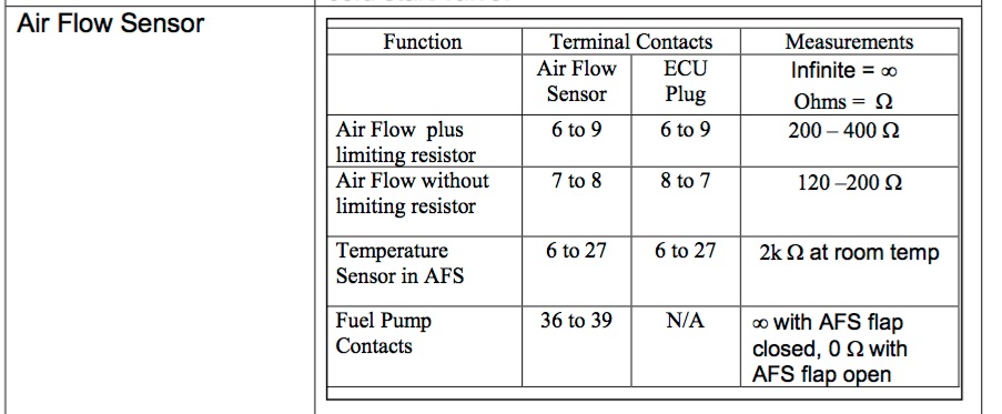
the factory workshop manual i have (and which you have downloaded from the same place) does not have any updates that cover those later AFMs with further test info.
we can only really do the first two tests on that table on the 74 which doesn't really specifically isolate out the temp sensor - because you can't.
and.........this is the clincher.
even if you are able to test the temp sensor on the 74 or as you can on the 75 AFM i think you would be a brave man to try and replace it on either. its buried under the potentiomer board on the 74 and i think also still on the 75 and you would have to get that up.
i'm not sure i would want to dissassemble an AFM to that extent!!!!!
the "official" instruction in both cases is throw away the AFM and get a new one.
(i guess the rebuilders do pull them right apart, so they can replace the sensor when its all in pieces and they know how to put them back together again set up right?)
i notice that later on with L jet development that a lot of AFM units have a temp sensor that is fixed down with two screws and sufficient space is available inside the AFM to position it off to the side of the board so it can be accessed and presumably easily replaced if defective. that does not seem to be the case with our early AFM.
-------
as an aside on the myth of the 6 pin having no temp sensor, this may have basis in some fact. VW did fit a 6 pin AFM to some type 4 buses in 75 and 76 and it is claimed that AFM unit did not have a temp sensor. instead the air intake to the air cleaner used an air pre heat pipe to supply air at a regulated warm temp. hence no need for temp sensor might have been the thinking by VW. i think sometimes that 6 pin AFM might get confused with the 6 pin AFM on 74 914s and also 74 412Es.
----
i think StarBear's best bet is to replace that AFM he has with the one he has spare and see if his hot day/high humidity problem goes away.
oddly i could think of a simple test he could do if it happens to him again and if he has a deep multi storey basement car park in his vicinity. usually if you can drive down to the bottom levels of those both the air temp and the humidity levels drop. its a trick some folks used to do way back in the day in brisbane (its hot as hell and tropical level humid there). they would go drive down to the bottom of an office tower car park. and stand around to cool down on a hot day. usually with a 6 pack of XXXX in the trunk to assist but if it was the heat and humidity that was doing it via a defective air temp sensor i'm betting the car would come good at the bottom of one of those carparks. however probably not one conveniently nearby to where he lives in the vicinity of leafy bernardsville as i remember that area. in a funny sort of way that empirical test would confirm things as much as a fancy old EDAW machine would?
Posted by: Van B Jun 9 2023, 08:39 AM
I yeah that was frustrating to not be able to test the sensor directly. I didn't catch what you pointed out about that table because of its placement in the manual and the TSII numbers are the same as later in the AFC troubleshooting so it gave me confirmation bias. As much as my Air Force brain hates that I reference the technical manual incorrectly, I appreciate the course correction!
Van
Posted by: StarBear Jun 9 2023, 09:32 AM
Great discourse! Informative and methodical, too.
There is a multi level parking deck in Morristown. Will do that trial first! Thanks for the suggestion, @wonkipop!
Posted by: ClayPerrine Jun 9 2023, 10:23 AM
There is a way to test the temp sender in a 6-Pin air flow meter.
The temp sender and the vane air meter use a common ground, but the signal wire from the temp sender is not shared. So you can test between the signal wire and ground.
I am at work right now, but when I get home, I will get one of the many air flow meters I have a test it.. with pictures.
Clay
Posted by: wonkipop Jun 9 2023, 03:41 PM
There is a way to test the temp sender in a 6-Pin air flow meter.
The temp sender and the vane air meter use a common ground, but the signal wire from the temp sender is not shared. So you can test between the signal wire and ground.
I am at work right now, but when I get home, I will get one of the many air flow meters I have a test it.. with pictures.
Clay
that would be great if you have that procedure clay.
my electrically retarded brain needs hand holding for this.
Posted by: wonkipop Jun 9 2023, 03:49 PM
Great discourse! Informative and methodical, too.
There is a multi level parking deck in Morristown. Will do that trial first! Thanks for the suggestion, @wonkipop!
its got to be an underground basement car park.
deep enough and big enough for the stable ground temp to influence the concrete.
concrete will usually settle at the average annual temp for the region if its also insulated or separated enough from atmospheric air temp up above ground. concrete is also a very good conductor so you need to be in the deepest zone of the car park where its least altered by above ground conditions.
if its deep enough down the air in it will also rest/stratify in layers and the hot air from outside won't overly mix with the cooler air down low. the concrete (if its not sealed or painted) will also absorb a lot of the moisture in the humid air and dehumidify it. you will know because it will be cooler and drier down there and more like one of your standard less humid summer days.
if you can find one with the right environment you should be able to drive in with the car experiencing the symptoms you are talking about on a very hot and humid day and it should settle down again to its behaviour on cooler less humid days - seems to me like a good way to test your theory with some real world conditions you can sort of simulate.
otherwise find a giant drive in refridgerator.
Posted by: ClayPerrine Jun 13 2023, 06:32 AM
Finally got up int he attic this morning to get an AFM. I am not getting up there in the afternoon when the outside air temp is 100 Degrees F.
First picture is the plug on the 6 pin Air flow meter.
From left to right, the pin numbers are 39, 36, 6. 9, 8, 7.
Second picture is the inside of the AFM.
The two black wires come from the Air temp sensor.
The easiest way to test the temp sensor is to open the air flow meter, and disconnect one of the wires from the contact going back into the AFM plug.
It should be about 5.7 ohms at ambient room temp. I don't have a chart for but it is about 78 degrees F in here right now.
Pins 39 and 36 are the fuel pump contacts
Pin 7 goes to the center pivot contact for the air flow meter.
Pin 8 is the air flow meter signal.
Pin 9 is the common wire between the meter and the temp sensor.
Pin 6 is the temp sensor. There is some resistance added to the circuit in the AFM before it is presented to the harness. The connection at the harness reads 281 ohms at 78F.
I hope that helps everyone.
Posted by: StarBear Jun 13 2023, 08:55 AM
@http://www.914world.com/bbs2/index.php?showuser=1143
Very informative!
Questions: Does it matter which wire to disconnect? With battery disconnected?
Once tested, might use hair dryer on sensor to see if there are changes.
Took the car for a long drive this morning. Engine temp nice and hot; air temp in the low 70s and mild humidity. Ran flawlessly. Confirms hot/humid intake air is the instigator.
Will report back.
Thanks!
Posted by: ClayPerrine Jun 13 2023, 09:27 AM
@http://www.914world.com/bbs2/index.php?showuser=1143
Very informative!
Questions: Does it matter which wire to disconnect? With battery disconnected?
Once tested, might use hair dryer on sensor to see if there are changes.
Took the car for a long drive this morning. Engine temp nice and hot; air temp in the low 70s and mild humidity. Ran flawlessly. Confirms hot/humid intake air is the instigator.
Will report back.
Thanks!
You only need to remove one of the two wires. Do so gently so you don't break the connector.
Hair dryer to warm the sensor is a good idea.
Clay
Posted by: StarBear Jun 13 2023, 09:36 AM
And another twist - I have a supposed NOS AFM for data comparison!
Posted by: StarBear Jun 13 2023, 12:01 PM
Have data for the NOS/lightly used AFM. Approximate temps of freezer, basement, outside, and hair dryer as don’t have a proper thermometer for the range.
Will do in car AFM this weekend and report back fully.
Adding to the 1.8 knowledge base!
@http://www.914world.com/bbs2/index.php?showuser=1143
@http://www.914world.com/bbs2/index.php?showuser=24231
@http://www.914world.com/bbs2/index.php?showuser=15080
Will include Van B and Big Len when done.
Posted by: wonkipop Jun 13 2023, 09:03 PM
@http://www.914world.com/bbs2/index.php?showuser=1143
thanks for the AFM pics and info.
filed away. hopefully never to need (wishful thinking maybe with 50 year old AFM).
Posted by: StarBear Jun 15 2023, 10:34 AM
Now this just got real interesting!
Opened the NOS unit, inspected, and took data measurements as @http://www.914world.com/bbs2/index.php?showuser=1143 suggested. Will post results separately.
Opened my original in-car unit, inspected -- and noticed significant differences between the two units' internals.
1. My original unit has no black wires (as believed and indicated by @http://www.914world.com/bbs2/index.php?showuser=24231 ), and two part numbers on the black cover cap. See pic. This one has an "011" ending number on the internal mechanism.
2. The NOS unit, still in its original box, has the same part number but 3 differences inside (including the 2 black wires) and only one part number on the black cover cap. See pic This latter one has an "021" ending number on the internal mechanism - a superceded version.
A few other small differences, like Phillips head screws on the body instead of slotted screws, etc, but all minor
Seems like (?) Bosch superceded the mechanism part, but not for VW?? 


Posted by: StarBear Jun 15 2023, 03:06 PM
[Edited and corrected to indicate first version of 6-pin AFM CAN be tested, although indirectly. Updated PDF and pic.]
@http://www.914world.com/bbs2/index.php?showuser=24231
@http://www.914world.com/bbs2/index.php?showuser=16126
@http://www.914world.com/bbs2/index.php?showuser=26011
@http://www.914world.com/bbs2/index.php?showuser=15080
OK; here's the test data I got for the NOS 6-pin AFM Temp Sensor II. Not scientific accuracy due to lack of a proper thermometer, but close enough to get resistance characteristics and determine if the sensor is kaput.
NOTE: Only for the superceded "..021" version of the 6-pin AFM, with the two black wires; doesn't appy to the "..011" version of the 6-pin AFM, with no black wires. Never knew there were two versions. See posting above. TESTING_THE_TEMP_II_SENSOR.pdf ( 229.54k )
Number of downloads: 30
TESTING_THE_TEMP_II_SENSOR.pdf ( 229.54k )
Number of downloads: 30

Posted by: ClayPerrine Jun 16 2023, 05:57 AM
The original CAN be tested. But the values will be quite different from what you got testing the sensor directly.
Pin 9 is the common wire between the meter and the temp sensor.
Pin 6 is the temp sensor. There is some resistance added to the circuit in the AFM before it is presented to the harness. The connection at the harness reads 281 ohms at 78F.
The board in the AFM adds resistance to the temp sensor circuit, so the readings won't be the same as the ones checking at the wires. But you can hook the wires back up and repeat the temp testing at the AFM plug.
Posted by: StarBear Jun 16 2023, 07:24 AM
The original CAN be tested. But the values will be quite different from what you got testing the sensor directly.
Pin 9 is the common wire between the meter and the temp sensor.
Pin 6 is the temp sensor. There is some resistance added to the circuit in the AFM before it is presented to the harness. The connection at the harness reads 281 ohms at 78F.
The board in the AFM adds resistance to the temp sensor circuit, so the readings won't be the same as the ones checking at the wires. But you can hook the wires back up and repeat the temp testing at the AFM plug.
Hmmm. Will try that. Thanks.
Posted by: StarBear Jun 16 2023, 02:26 PM
Ok; tested the current unit per Clay's suggestion and found discontinuity between pins 6 and 9. Seems to say to me that the temp sensor II is kaput.
Have swapped out the old, original AFM (original version) for the NOS one (second version) with a suitable 282 ohms resistance b/n the two pins.
Will give it a try tomorrow afternoon if the air temp is warm. Hopefully, this was (past tense!) the source of my low idle trouble at warm air temps. 
Posted by: wonkipop Jun 16 2023, 07:16 PM
@http://www.914world.com/bbs2/index.php?showuser=10753
mine is the same as your original.
has the bosch and VW part #
suspect its interior is the same as yours as well.
mine is a jan 74 car about 2 months after yours.
i think the way it works with branded parts that have the car manufacturers logo as well as the component manufacturer numbers and logo is that these are what were originally installed on the production line. as time goes on replacement spare parts tend to have only the component manufacturer's branding and part #.
we found the same thing when we pulled the flywheel off to do the clutch a couple of years ago.
the flywheel washer was original factory installed as was the clutch (long obsolete rubber core clutch). the washer was branded with VW logo. also carried the component makers logo which is the other graphic stamped on it. i forget whose graphic that is but somewhere i have an old VW book that lists all these different manufacturers and logos. these days the replacement washers have long since ceased to be VW branded.

i think the AFMs that carry the VW logo are the original babies.
although they could also have been original production line installed that have been rebuilt. the one you have without the VW branding is a later Bosch spare part.
it looks to me that even though they are 6 pin the interior components installed are later improvements along the way, including giving you access to the temp sensor.
i have not taken my apart but i'm guessing like the original you have pulled off and opened mine has no capacity to test that sensor like the ones that have the separate wires and plugs.
i'll take on board @http://www.914world.com/bbs2/index.php?showuser=1143 's comment and info and file that away.
Powered by Invision Power Board (http://www.invisionboard.com)
© Invision Power Services (http://www.invisionpower.com)