Printable Version of Topic
Click here to view this topic in its original format
914World.com _ 914World Garage _ 1974 Headlight Switch pinout
Posted by: mgarrison Sep 16 2023, 12:16 PM
Hello,
I was hoping to reuse the light switch that was in my 74, but I am really struggling with the "current flow diagram" vs a typical "wiring diagram". The wiring diagram for the 71 is much easier for my addled brain to follow. However, the 71 used a different light switch with fewer connections, so not much help!
I no longer have popups, so I wont be using those connections, but hoping to use the connections for parking lights, headlights, and maybe the dimmer (knob twist) for the gauge lights.
Here's what I THINK I have ferreted out from the 74 current flow diagram in the service manuals: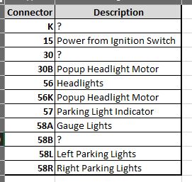
Here's the best pic I could get of my light switch that shows most of the connection numbers (11 total connections):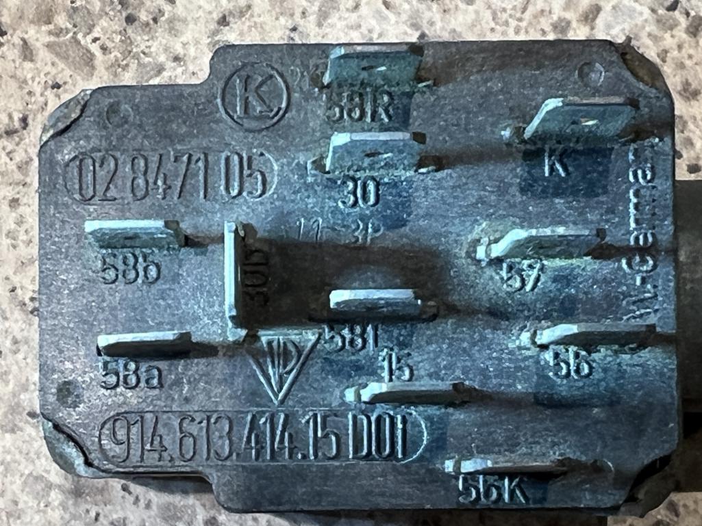
I hoping someone can maybe confirm what I have so far as accurate, or even better share where each connections goes/it's purpose 
Posted by: 87m491 Sep 17 2023, 01:01 PM
According to the current flow diagram,
30 is power to the headlight motors, K is power to instrument bulbs via the dimmer.

Hello,
I was hoping to reuse the light switch that was in my 74, but I am really struggling with the "current flow diagram" vs a typical "wiring diagram". The wiring diagram for the 71 is much easier for my addled brain to follow. However, the 71 used a different light switch with fewer connections, so not much help!
I no longer have popups, so I wont be using those connections, but hoping to use the connections for parking lights, headlights, and maybe the dimmer (knob twist) for the gauge lights.
Here's what I THINK I have ferreted out from the 74 current flow diagram in the service manuals:
Here's the best pic I could get of my light switch that shows most of the connection numbers (11 total connections):
I hoping someone can maybe confirm what I have so far as accurate, or even better share where each connections goes/it's purpose
Posted by: JeffBowlsby Sep 17 2023, 03:14 PM
If it helps you here is a link to a https://bowlsby.net/914/WiringHarnesses/docs/DashSwitches.pdf circuit diagram on my harness website for the headlight switches. Various combinations of those connection tabs connect to different circuits dependent on what position the pull switch is in.
Posted by: davep Sep 17 2023, 06:11 PM
K: illumination output for instruments. goes to fuse 7 input. often has a jumper for 58b but I replace with a wire from fuse 7 output so that the gauge lights are fused; several harnesses I have see had the jumper and other wires totally fried.
30: battery hot wire from fuse 10 input
30B: connected to 30 when switch is off, puts headlights in down position
58a: dimmer output for gauge illumination
58b: dimmer input; do yourself a favor and source from fuse 7 output
Posted by: mgarrison Sep 18 2023, 08:05 AM
Thanks everyone - much appreciated!
Posted by: mgarrison Sep 18 2023, 08:24 AM
If it helps you here is a link to a https://bowlsby.net/914/WiringHarnesses/docs/DashSwitches.pdf circuit diagram on my harness website for the headlight switches. Various combinations of those connection tabs connect to different circuits dependent on what position the pull switch is in.
Your diagrams are a huge help!
Powered by Invision Power Board (http://www.invisionboard.com)
© Invision Power Services (http://www.invisionpower.com)