Printable Version of Topic
Click here to view this topic in its original format
914World.com _ 914World Garage _ Oil Leaks
Posted by: sdoolin Nov 19 2023, 01:57 PM
Rebuilt my 2.0 back in 2016. Full "Raby Spec" 2056. Runs very well. It is out of the car right now as I am dealing with a rusty battery tray (separate thread on that). It appears that I have leaks at most/all of the pushrod tube seals, the valve cover seals, and the rear main seal. This is not a surprise to me, I clean the bottom of the engine regularly, and knew this day was coming
Pretty sure I used the Victor Reinz gasket set that came with my engine "kit" from the Type IV Store. I used the cork valve cover seals from the Victor Reinz set. I did not use any RTV anywhere. Hate the stuff. I know I used a rear main seal from GoWesty as someone back then had suggested it is a better part then what is included with the Victor Reinz set.
I installed new pushrod tubes and used the O-Rings from the Victor Reinz set.
Does anyone really have an oil tight VW Type IV engine? If yes, how does none do that?
Posted by: Shivers Nov 19 2023, 02:26 PM
That is the rumor. My last T-4 build didn’t leak a drop till I put oil in it and started it. I always thought it was why they made the P tube's and valve cover gaskets so easy to replace. Gets pretty hot in socal.
Posted by: 914sgofast2 Nov 19 2023, 02:43 PM
Jake Raby did a video about his frustration in finding a RMS that won’t leak. The video used to be on his Facebook page but he deleted it. In a nutshell, he concluded that no one sells a RMS that is any good. He found a seal he liked that doesn’t leak by using one from a military helicopter, but he is not revealing the source or identifying the seal info. There is another fix he discussed by adding third hole to the rear of the engine case so the oil trapped in the void at the rear of the main bearing can quickly drain back into the case. He said an upper hole has to be made as an air vent to prevent a vacuum forming between the bearing and the seal. If you look at your engine case you will see 2 drain back holes, but they are at the same level, so air can’t get in to that area and allow the oil to drain out.
Posted by: 930cabman Nov 19 2023, 05:12 PM
My 2056 build has a couple smallish pushrod tubes leaking, it's on the list for work items this winter. I will be dropping the engine to clean up a couple other items
Posted by: Geezer914 Nov 19 2023, 05:27 PM
I have a 26mm type 1 CB performance oil pump that puts out 78 psi at start up with Driven 15w50 oil. I have a few drips in the front which I think is from seeping past the oil cooler seals until the oil pressure drops to normal. Rear seal drips. I used an Elring oil seal vs the Victor Reinz. So it leaves a few drops on the floor to mark it's turf. It could be worse if you owned an XKE Jag!
Posted by: JeffBowlsby Nov 19 2023, 05:59 PM
Jake also used to recommend plumbers pipe dope with Teflon in it for the pushrod tubes.
Posted by: Literati914 Nov 19 2023, 06:10 PM
what about the spring loaded tubes, effective or not?
.
Posted by: Shivers Nov 19 2023, 08:14 PM

what about the spring loaded tubes, effective or not?
.
On a type one, they would function. Don’t know if they would leak. But the type 4 push rod tube doesn’t work like that.
Posted by: AZBanks Nov 19 2023, 10:34 PM
what about the spring loaded tubes, effective or not?
.
On a type one, they would function. Don’t know if they would leak. But the type 4 push rod tube doesn’t work like that.
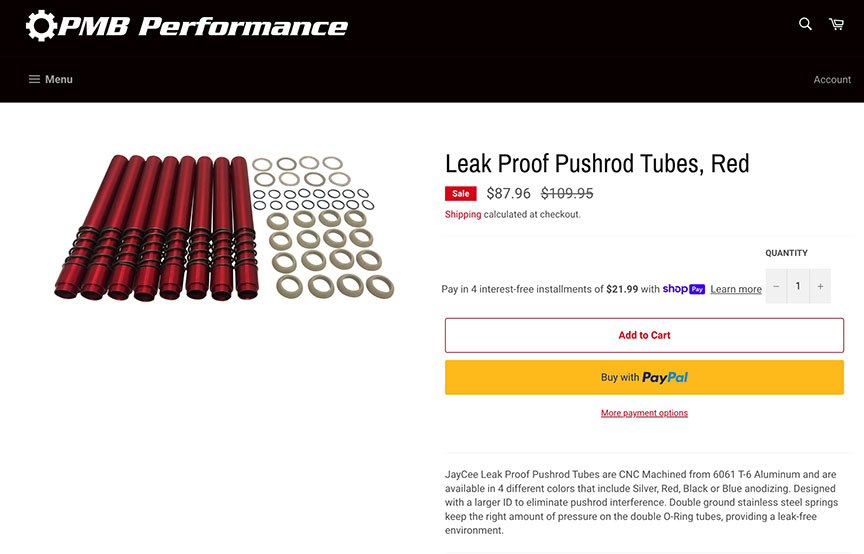
I think he is talking about the "Leak Proof Pushrod Tubes" you can get from PMB Performance.
I recently installed them on my car and so far, so good but it has been less than 1000 miles.
I've got an oil leak but it is not in the pushrod tubes.
Posted by: barefoot Nov 20 2023, 07:57 AM
For push rod tube seals, I didn't use the green ones from the kit but used
Parker 2-212 & 2-214 size Viton seals, no leaks. (I worked for Parker back then)
Barefoot
Posted by: Geezer914 Nov 20 2023, 08:04 AM
McMaster-Carr chemical resistant viton fluoroelastomer 1/8 fractional width, O-ring X profile.
2126540k152 (small end)
2146540k154 (large end)
Coat with DuPont Molycote 55 O ring grease.
No leaks!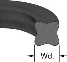
Posted by: VaccaRabite Nov 20 2023, 08:59 AM
I always fight with pushrod tube seals. You have to grease them prior to installing them. You also have to be sure the bores are CLEAN. If they are dirty, or have any burrs, you will end up with a pinched or cut pushrod tube seal and a leak.
Zach
Posted by: sdoolin Nov 20 2023, 09:10 AM
McMaster-Carr chemical resistant viton fluoroelastomer 1/8 fractional width, O-ring X profile.
2126540k152 (small end)
2146540k154 (large end)
Coat with DuPont Molycote 55 O ring grease.
No leaks!
This is a beautiful thing. I'm ordering these seals and the grease today.
Posted by: sdoolin Nov 20 2023, 09:48 AM
Thanks for all replies...
I have tried to find the McMaster-Carr X-ring seals, but alas, McMaster-Carr either no longer offers them, they have been superseded to a new part number, and/or my internet search skills are lousy. Very likely the later. If anyone has a good part number I'd love the assist.
Also, what is the current group-think regarding bolt on valve covers from LE (Type IV Store)? I think decades ago the BugPack bolt on valve covers were shamed? It sure seems like bolting these covers on would resist oil leakage better than the bales? Plus I think they look cool.
Posted by: Geezer914 Nov 20 2023, 10:44 AM
Thanks for all replies...
I have tried to find the McMaster-Carr X-ring seals, but alas, McMaster-Carr either no longer offers them, they have been superseded to a new part number, and/or my internet search skills are lousy. Very likely the later. If anyone has a good part number I'd love the assist.
Also, what is the current group-think regarding bolt on valve covers from LE (Type IV Store)? I think decades ago the BugPack bolt on valve covers were shamed? It sure seems like bolting these covers on would resist oil leakage better than the bales? Plus I think they look cool.
Go to McMaster Carr web page. In the search type in 212. It will take you to the o ring profile page. Click on the X ring profile. 212 is 7/8 ID x 1 1/8 OD. Then go back to the search box and type in 214, and do the same. 214 is 1 ID x 1 1/4 OD The 6540K152 and 6540K154 will be at the end of the line by the pricing.
Posted by: FlacaProductions Nov 20 2023, 10:57 AM
Nice:
Here's the direct links -
212:
https://www.mcmaster.com/products/o-rings/dash-number~212/square-profile-oil-resistant-buna-n-o-rings/
and the 214:
https://www.mcmaster.com/products/o-rings/dash-number~214/square-profile-oil-resistant-buna-n-o-rings/
Posted by: Geezer914 Nov 20 2023, 11:36 AM
I had a pair of cast aluminium valve covers and it appeared they would not fit.
Posted by: technicalninja Nov 20 2023, 12:11 PM
Took a bit to find the x shaped viton rings.
this is the page I'll order off of.
https://www.mcmaster.com/products/o-rings/x-profile-chemical-resistant-viton-fluoroelastomer-o-rings/
Just find 212 and 214 in the 1/8" selection.
The other fractional sizes don't exactly match the dimensions.
Thanks to Geezer914 for the initial heads up on these.
I like them a bunch better than regular or square cut versions.
Flaca's link are buna and square cut.
The smaller ones are in packs to 10, the bigger packs of 5 (darn it all!)
Posted by: 914werke Nov 20 2023, 12:22 PM
Im in agreement but cant get past the $$

Posted by: sdoolin Nov 20 2023, 12:40 PM
Thank you geezer for the explicit instructions - very helpful. I had to order a pack of 100 of the 212s, and a pack of 25 of the 214s. Which is fine. I'll have plenty of spares for the community. Looks like they will be here tomorrow. Ordered the Dupont Molykote 55 a little earlier. It ships in a week.
Feeling good about the solution!
Posted by: sdoolin Nov 20 2023, 12:43 PM
Im in agreement but cant get past the $$
I'm with you, I hadn't noticed the price. Sheesh that is a LOT.
Posted by: technicalninja Nov 20 2023, 12:48 PM
Jake Raby did a video about his frustration in finding a RMS that won’t leak. The video used to be on his Facebook page but he deleted it. In a nutshell, he concluded that no one sells a RMS that is any good. He found a seal he liked that doesn’t leak by using one from a military helicopter, but he is not revealing the source or identifying the seal info. There is another fix he discussed by adding third hole to the rear of the engine case so the oil trapped in the void at the rear of the main bearing can quickly drain back into the case. He said an upper hole has to be made as an air vent to prevent a vacuum forming between the bearing and the seal. If you look at your engine case you will see 2 drain back holes, but they are at the same level, so air can’t get in to that area and allow the oil to drain out.
I'm betting he found a reverse style seal.
All the manufactures are moving in this direction.
The rear seal for Gen 3 GM small blocks and Mazda/Ford 2.0-2.5l engines are reverse lip style. I've NEVER seen one leak...
As crankcase pressure goes up these seal even better.
When I need one for my T4, I'm going to research this...
I've got a 98 M3. The original seal ($20) has been replaced by one of this style seal.
The "new" seal is over $80...
I've been drilling extra holes in seal bores for decades (just like Raby) I've never done a RMS like this but cam seals all can be helped by adding and increasing drain back and vent passages.
Posted by: Jack Standz Nov 20 2023, 12:59 PM
The silicone valve cover gaskets Aircooled.Net used to sell work so much better than the cork ones. Not sure who sells those anymore, but take a look:
https://www.cbperformance.com/category-s/407.htm?searching=Y&sort=5&search=valve%20cover%20gasket&show=15&page=1
Posted by: sdoolin Nov 20 2023, 01:07 PM
The silicone valve cover gaskets Aircooled.Net used to sell work so much better than the cork ones. Not sure who sells those anymore, but take a look:
https://www.cbperformance.com/category-s/407.htm?searching=Y&sort=5&search=valve%20cover%20gasket&show=15&page=1
Thank you for that. I broke down and ordered a set of the CB bolt on valve covers. I have literally wanted a set since I built my first bus engine in college (in mid 80's). I couldn't afford them back then. Now even if they don't cure an oil leak, I'll have them in the shop.
914World Rocks!
Posted by: VaccaRabite Nov 20 2023, 01:43 PM
Regular valve covers work fine. You don't need a special bolt on deal.
For valve cover gaskets, I have always had a lot of success using a standard cork gasket. I use a THIN smear of RTV on the side of the gasket that goes into the valve cover to hold it in place. I do not use ANY RTV on the side of the gasket that goes on the head.
Using this method, a standard cork valve cover gasket will last years and several on off cycles.
Zach
Posted by: ctc911ctc Nov 20 2023, 02:39 PM
'74 2.0, 28k miles
I tried to tighten the leaks with the engine in the car, 4-5 tries and then I took the engine out, tore near everything off (cylinders stayed on) and cleaned and cleaned and cleaned until all of the oil marks were removed. 
all rubber/synthetic(?) seals were replaced: front/rear, the most important oil cooler seals, and all of the push-rod seals. I bought a few new push rod tubes, a couple were bent and well, did not look very good. I did not use any LTV for anything because of the high operating temperature. (this is an opinion only). I used Permatex 80017 to secure the push-rod tubes seals and the others so when placed into position they stay in that position, and it may provide that little bit extra sealant. Though the odor is not very good I have had good results with Permatex - I think sealants, after I have had a few years of experience with them, is a matter of learning how to use the one of choice, all are a bit nuanced (again, opinion) and one persons perfect sealant is another persons evil sealant. 
The engine has been in for 2 years, not a leak. I did have one or two of the push-rod tubes start seeping in the beginning, I removed them with the engine in the car and then re-sealed with great success. 
Not a drop on my garage floor. 
CTC911CTC
Posted by: Geezer914 Nov 20 2023, 03:02 PM
Second that, Permatex Hi Tac gasket cement on the valve cover side and a light coat of grease on the side towards the head. 914 Rubber sells a thicker cork gasket if your bails are week.
Posted by: FlacaProductions Nov 20 2023, 03:37 PM
The VW logo on the cover goes UPSIDE DOWN when the cover is installed correctly. I use Gasgacinch 440-A between
the gasket and valve cover. Dry between the gasket and head.
I use standard cork Victor Reinz gaskets - I tried the extra thick ones and they were too thick for me.
Permatex Aviation Gasket sealant on gaskets like taco plate and tuna can.
Been working for me - not a drip other than from the oil pressure extension hose threads - which was eliminated with some (wait for it) Permatex Aviation Gasket sealant.
Posted by: bkrantz Nov 20 2023, 08:53 PM
The truly leak-free type 4 engine might be a fantasy. I chased that grail for a year, which involved multiple engine drops. In the end I think (knock on wooden head) got all the significant leaks, but I know a couple of places, including push-rod tubes) still weep a bit. Good luck.
Posted by: brant Nov 21 2023, 10:50 AM
pushrod seals are an o ring...
they are designed to spin or be free to turn
any type of RTV on those seals is not correct.
Posted by: wonkipop Nov 22 2023, 01:15 AM
pushrod seals are an o ring...
they are designed to spin or be free to turn
any type of RTV on those seals is not correct.
yeo
Posted by: sdoolin Nov 30 2023, 07:08 PM
Still working on teardown, finding pretty much what I thought I would. I was expecting evidence of pushrod tube seal leakage, RMS leakage, and even oil pump gasket leakage, all fixable. In the pic below, I'm curious about the amount of oil on the base of the jugs where they get very friendly with the case. Also the amount of oil on the studs. This is above the inner pushrod tube seals, but it seems (to me) like I may be leaking at the base of the jugs? Which I would hate? Interestingly, and just to jinx myself, the oil cooler seals are nice and dry. There about 6K miles on this engine since complete rebuild.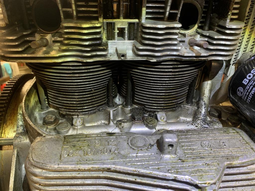
Posted by: Porschef Dec 1 2023, 06:36 AM
Really despise oil leaks. I suppose owning an air cooled vehicle doesn’t make much sense but I digress... My engine leaves a series of oil markings that keep me from parking in certain places without a diaper (sheet of cardboard). Seems to be coming primarily from the front; I suspect the oil pump or front seal, that leak then blows back along the bottom of the engine making it difficult to find any possible additional leaks.
Anyway, I hope to pull the engine over the winter to address this, hope being the operative word... 
Posted by: burton73 Dec 1 2023, 01:05 PM
what about the spring loaded tubes, effective or not?
.
On a type one, they would function. Don’t know if they would leak. But the type 4 push rod tube doesn’t work like that.
I think he is talking about the "Leak Proof Pushrod Tubes" you can get from PMB Performance.
I recently installed them on my car and so far, so good but it has been less than 1000 miles.
I've got an oil leak but it is not in the pushrod tubes.
Picture of the PMB Tubes
Bob B
Try this
Posted by: Olympic 914 Dec 1 2023, 01:13 PM
Wow those tubes look nice. don't think I want to pull the engine just to install them though.
But one more thing to think about....
Posted by: Literati914 Dec 1 2023, 01:21 PM
what about the spring loaded tubes, effective or not?
.
On a type one, they would function. Don’t know if they would leak. But the type 4 push rod tube doesn’t work like that.
I think he is talking about the "Leak Proof Pushrod Tubes" you can get from PMB Performance.
I recently installed them on my car and so far, so good but it has been less than 1000 miles.
I've got an oil leak but it is not in the pushrod tubes.
Picture of the PMB Tubes
Bob B
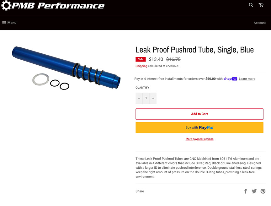
That's them, knew I'd seen them somewhere.. think I'll pick up a set at some point (but hey they are currently on sale
 ).
).
Posted by: Jack Standz Dec 1 2023, 01:31 PM
Wow those tubes look nice. don't think I want to pull the engine just to install them though.
But one more thing to think about....
You don't need to pull the engine to install the pushrod tubes. But, yes it is easier to install them on an engine stand.
Just looked closer at the above pushrod tubes. Those are for a type I VW, not a 914 head.
Posted by: sdoolin Dec 1 2023, 06:19 PM
I have ordered new pushrod tubes from TIVStore, have the fancy McMaster-Carr X-ring pushrod tube seals, and various other new gaskets. Much cleaning required before re-assembly.
Question:
What is current group-think on phenolic spacers and gaskets? I am running carbs (love them), and I use a gasket on each side of the phenolic spacer, which gives the intake manifold nuts precious little grip on the studs. Can I lose the paper gaskets?
Posted by: sdoolin Dec 1 2023, 06:22 PM
pushrod seals are an o ring...
they are designed to spin or be free to turn
any type of RTV on those seals is not correct.
Agree, and there is zero RTV on this engine. When I was younger I "may have" used a pound of RTV on a bus engine.
Posted by: Geezer914 Dec 2 2023, 07:19 AM
DuPont Moly coat 55 O ring grease!
Posted by: Front yard mechanic Dec 2 2023, 08:17 AM
It’s called controled seepage
Posted by: porschetub Dec 2 2023, 03:31 PM
The silicone valve cover gaskets Aircooled.Net used to sell work so much better than the cork ones. Not sure who sells those anymore, but take a look:
https://www.cbperformance.com/category-s/407.htm?searching=Y&sort=5&search=valve%20cover%20gasket&show=15&page=1
Thank you for that. I broke down and ordered a set of the CB bolt on valve covers. I have literally wanted a set since I built my first bus engine in college (in mid 80's). I couldn't afford them back then. Now even if they don't cure an oil leak, I'll have them in the shop.
914World Rocks!
Good they should be fine ,just be aware you really need to replace the rocker studs to heavy duty ones that have 8mm thread on the outside ,the puny 7mm stock ones are not up to holding rocker gear and the alloy cover .
Edit ....just had a look on CB listing ,keen sale price and they come with correct hardware so as mentioned you be happy with these .
When removing the old studs from the your heads it pays to head the stud bosses up to help them unscrew so you don't pull the threads ,I found them rather tight on my last build with these alloy covers, sorry but don't remember what torque I used but that should be in the instructions or call CB ,cheers.
Posted by: Literati914 Dec 2 2023, 03:45 PM
..Just looked closer at the above pushrod tubes. Those are for a type I VW, not a 914 head.
OK and there's multiple options for these on a VW 1600 apparently - so strange if nobody offered the same for a type 4.. I didn't take much time looking into it but I wonder if there are any options via the aircraft industry. If not, then here's a business opportunity for some industrious types.
.
Posted by: sdoolin Dec 2 2023, 06:34 PM
DuPont Moly coat 55 O ring grease!
I have a brand new, fresh tube of it!
Posted by: sdoolin Dec 2 2023, 06:42 PM
Spent all day cleaning. Have a pretty good contact cleaner & bourbon buzz. Waiting for new pushrod tubes and various gaskets. I have questions about phenolic spacers and exhaust bolts...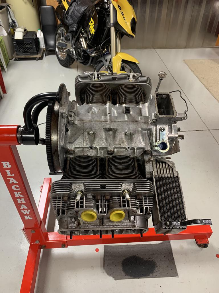
Posted by: sdoolin Dec 2 2023, 06:46 PM
The silicone valve cover gaskets Aircooled.Net used to sell work so much better than the cork ones. Not sure who sells those anymore, but take a look:
https://www.cbperformance.com/category-s/407.htm?searching=Y&sort=5&search=valve%20cover%20gasket&show=15&page=1
Thank you for that. I broke down and ordered a set of the CB bolt on valve covers. I have literally wanted a set since I built my first bus engine in college (in mid 80's). I couldn't afford them back then. Now even if they don't cure an oil leak, I'll have them in the shop.
914World Rocks!
Good they should be fine ,just be aware you really need to replace the rocker studs to heavy duty ones that have 8mm thread on the outside ,the puny 7mm stock ones are not up to holding rocker gear and the alloy cover .
Edit ....just had a look on CB listing ,keen sale price and they come with correct hardware so as mentioned you be happy with these .
When removing the old studs from the your heads it pays to head the stud bosses up to help them unscrew so you don't pull the threads ,I found them rather tight on my last build with these alloy covers, sorry but don't remember what torque I used but that should be in the instructions or call CB ,cheers.
Thank you for this bit of info. CB is waiting on gaskets to ship my bolt on covers. I will revisit this when I get to this point in the assembly.
Posted by: Geezer914 Dec 3 2023, 08:54 AM
Did you install the engine with these covers? I had a set of cast aluminum covers and when I tried to install them with the engine in the car, I ran into clearance issues.
Posted by: ClayPerrine Dec 3 2023, 09:07 AM
..Just looked closer at the above pushrod tubes. Those are for a type I VW, not a 914 head.
OK and there's multiple options for these on a VW 1600 apparently - so strange if nobody offered the same for a type 4.. I didn't take much time looking into it but I wonder if there are any options via the aircraft industry. If not, then here's a business opportunity for some industrious types.
.
I have a set of those fancy valve covers for a Type IV. Not worth the money. They don't prevent leaks any better than the stock covers, and the rubber gaskets are hard to find.
If I can find all the hardware for them, you can have them for free.
Posted by: sdoolin Dec 4 2023, 09:02 AM
..Just looked closer at the above pushrod tubes. Those are for a type I VW, not a 914 head.
OK and there's multiple options for these on a VW 1600 apparently - so strange if nobody offered the same for a type 4.. I didn't take much time looking into it but I wonder if there are any options via the aircraft industry. If not, then here's a business opportunity for some industrious types.
.
I have a set of those fancy valve covers for a Type IV. Not worth the money. They don't prevent leaks any better than the stock covers, and the rubber gaskets are hard to find.
If I can find all the hardware for them, you can have them for free.
Very kind offer. I have a set on order from CB. But if you wanna send yours away, I'll store them safely in my barn for decades.
Posted by: sdoolin Dec 4 2023, 09:24 AM
Thinking about phenolic spacers, the spacers between the cyl. head and the intake runners.
Do I need these if I am running carbs? I have been running them, along with a gasket on each side of them. I believe the rationale for running them is to provide some thermal barrier between the heads and the intake so as not to vaporize the gasoline in the float bowls. This has worked well, but the thickness of the two gaskets and the spacer gives the intake manifold nuts precious little bit on the studs?
Is there a sealant I can run in place of the gaskets and keep using the phenolic spacers?
Posted by: Superhawk996 Dec 4 2023, 09:47 AM
Or . . . wait for it . . . Longer studs?
Posted by: Geezer914 Dec 4 2023, 12:35 PM
If running carbs you should run phelonic spacers to keep the fuel from boiling in the float bowls.
Posted by: brant Dec 4 2023, 03:40 PM
Longer studs for carbs is a standard thing
You will need them
Posted by: sdoolin Dec 4 2023, 05:11 PM
Longer studs for carbs is a standard thing
You will need them
Longer studs it is then. Thank you. Longer is, after all, usually better. Strangely I'm not sure where to source longer studs, so help there would be appreciated. Studs on top of the intake runners could be longer too.
I really appreciate all the help from this site!
Posted by: sdoolin Dec 4 2023, 05:12 PM
Or . . . wait for it . . . Longer studs?
OK, I deserved that. Funny.
Posted by: sdoolin Dec 8 2023, 12:00 PM
More cleaning, inspection, and beginning of re-assembly. Fascinating the amount of grime accumulated in 6 yrs and 6K miles with what I kept telling myself were "minor oil leaks"....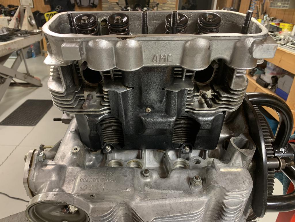
Posted by: Superhawk996 Dec 8 2023, 12:05 PM
Longer studs for carbs is a standard thing
You will need them
Longer studs it is then. Thank you. Longer is, after all, usually better. Strangely I'm not sure where to source longer studs, so help there would be appreciated. Studs on top of the intake runners could be longer too.
I really appreciate all the help from this site!
Belmetric is always a good 1st choice
https://belmetric.com/studs-and-rods/
Local hardware stores may have them but selection of lengths, thread pitch, and plating is usually very limited.
Posted by: rhodyguy Dec 8 2023, 12:30 PM
You are running the shorter version of intake manifolds. You’ll notice how the base is thicker for one stud. You can’t use phenolics without longer studs for the base thickness. Hassle….CB tall intakes have the same thickness for the whole base. Either switch to tall intakes or longer studs. Phenolic spacers really help with the heat soak issue.
Posted by: sdoolin Dec 8 2023, 01:42 PM
[/quote]
Belmetric is always a good 1st choice
https://belmetric.com/studs-and-rods/
Local hardware stores may have them but selection of lengths, thread pitch, and plating is usually very limited.
[/quote]
Appreciate the link for Belmetric. I will be spending money tonight!
Posted by: sdoolin Dec 9 2023, 10:17 AM
Attempts to remove existing intake studs have failed miserably. These are HAM heads, are 6 yrs old, and have about 6K miles on them. I have (of course) tried penetrating oil, and heat, all to no avail and I'm afraid I will pull the threads out of the heads. I am using the "double nut" method (pic below) and I get no movement on the stud.
Is there a special tool that I need to add to my collection of rarely used but significantly useful tools?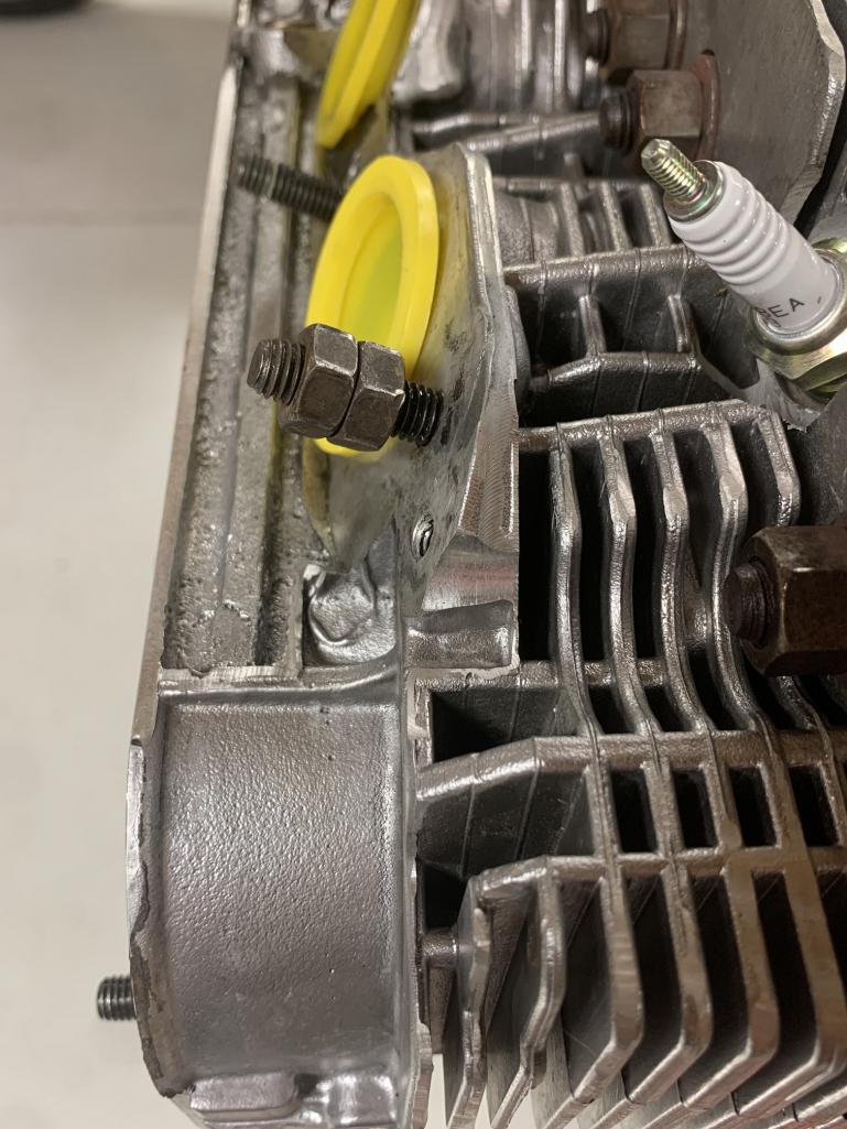
Posted by: Superhawk996 Dec 9 2023, 12:20 PM
Collet style stud install and removal tools specific to size and thread pitch are the best tool that will not damage threads.
I’ve never had intake studs break when being removed. My guess is they used some Loctite - need more heat! Aluminum is a great
Thermal conductor and moves heat away quickly. Plus the head and fins are helping to radiate the heat away and out of the head. You’ll need a lot of heat - like Oxy-Acetylene or the propane / MAPP gas for a while.
Heat the head around the stud - avoiding the stud or wrap stud with wet cloth to keep it cool. You want the aluminum to expand - not the stud.
These appear to be knockoff of Snap-on / Matco set I’ve used for about 1/3 the price 
Posted by: Dave_Darling Dec 9 2023, 12:55 PM
OK and there's multiple options for these on a VW 1600 apparently - so strange if nobody offered the same for a type 4..
Not needed for a Type IV. On a Type I (or 911) engine you have to remove the cylinder heads to install new pushrod (oil drain) tubes, because they are sandwiched between the case and the head. The two-piece spring-loaded tubes allow you to compress the length of the tube, put the new one in place, and then release to let the tube expand into position. (You would crush the old tube to pull it out.)
On the Type IV engine, the tubes just slide straight out of the head and case. The new tube just slides in. The more complex, more expensive tubes (that have an extra seal to leak!) are not needed. That said, there do seem to be some sold for the Type IV, or at least advertised for them.
--DD
Posted by: sdoolin Dec 9 2023, 01:43 PM
Thank you Superhawk996 - which reminds of two different motorcycles. Stud installer & remover kit on order.
I was using MAPP gas, but likely for not long enough. I will try again when the tool arrives.
Posted by: burton73 Dec 9 2023, 02:41 PM
pushrod seals are an o ring...
they are designed to spin or be free to turn
any type of RTV on those seals is not correct.
Agree, and there is zero RTV on this engine. When I was younger I "may have" used a pound of RTV on a bus engine.
RTV is 25 cubic inches per lb. How did I know that?
Posted by: sdoolin Dec 18 2023, 06:50 PM
More re-assembly today. The special "X-Ring" O-rings are a PITA, but I feel good about them. They were difficult to install, but I am hopeful that between these O-Rings and the Dow Molykote 55 grease I'll have less leakage at the pushrod tubes. Patience is key here (and bourbon). These X-Rings seem ever so slightly too big on the case-side, so "fenagling" was required.
I am terrible with my new expensive camera, so never mind the out of focus image.
CB Perf cast Al valve covers came with the wrong size adapters so I have to drill and tap one side of them to 8X1.25. That is for another day.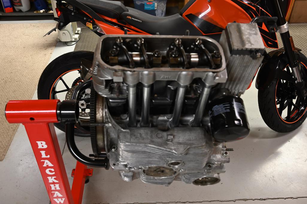
Posted by: porschetub Dec 18 2023, 08:37 PM
Thank you Superhawk996 - which reminds of two different motorcycles. Stud installer & remover kit on order.
I was using MAPP gas, but likely for not long enough. I will try again when the tool arrives.
More heat and cycle it several times around the head ,

Posted by: Dave_Darling Dec 20 2023, 03:20 PM
I do not like the bolt-on valve covers for our engines. The rocker studs are not the strongest, and the covers put even more stress on them. Plus a lot of people say that they "always leak". The stock stamped-steel covers work well if you put them on correctly.
--DD
Posted by: rjames Dec 20 2023, 03:28 PM
I do not like the bolt-on valve covers for our engines. The rocker studs are not the strongest, and the covers put even more stress on them. Plus a lot of people say that they "always leak". The stock stamped-steel covers work well if you put them on correctly.
--DD

The only time mine leaked is when I didn't get the cover on all the way. I've even reused the same cork gaskets before without an issue.
Posted by: porschetub Dec 20 2023, 05:54 PM
I do not like the bolt-on valve covers for our engines. The rocker studs are not the strongest, and the covers put even more stress on them. Plus a lot of people say that they "always leak". The stock stamped-steel covers work well if you put them on correctly.
--DD
Thats why i asked if he had the heavier 8mm studs and appears they are in the CB kit (see my reply ) that sorts the stud weakness , when I got my alloy covers these studs were missing and got the correct ones on the Samba .
A lot of people say this and that its a matter of doing it right ,cheers.
Posted by: sdoolin Jan 2 2024, 01:48 PM
I finally received the CB Performance bolt on valve covers, but the adapters (that clamp the rocker shaft on one side and the valve cover on the other) or 6mm on one side and 8mm on the other. The studs supplied with the kit are 8mm, and the rocker shaft studs are also 8mm. So I'll have to call CB and try to sort that out. Which sounds demoralizing.
New question: How to hold the crankshaft whilst removing (or installing) the flywheel? I can just zip the flywheel bolts out with an impact driver to remove them, but not sure how to hold the crank whilst installing them to correct torques spec? It's been 6 yrs since I built this engine last and I can't seem to remember what I did?
All help appreciated...
Posted by: Jack Standz Jan 2 2024, 02:35 PM
Available for approximately $20 to $25 from your favorite vendors:
https://www.autohausaz.com/pn/UN1201100
BTW a stock valve cover does work well if it's not too banged-up. But, if you have non-stock rocker arms/adjusters, the cast one from CB Performance clears rockers that won't fit in a stock valve cover and with the silicone rubber gaskets, they don't leak.
Posted by: ericoneal Jan 2 2024, 08:18 PM
I'm up the road from you in Crestwood and have one of these if you want to borrow it.
Available for approximately $20 to $25 from your favorite vendors:
https://www.autohausaz.com/pn/UN1201100
BTW a stock valve cover does work well if it's not too banged-up. But, if you have non-stock rocker arms/adjusters, the cast one from CB Performance clears rockers that won't fit in a stock valve cover and with the silicone rubber gaskets, they don't leak.
Posted by: sdoolin Jan 3 2024, 11:23 AM
I'm up the road from you in Crestwood and have one of these if you want to borrow it.
Available for approximately $20 to $25 from your favorite vendors:
https://www.autohausaz.com/pn/UN1201100
BTW a stock valve cover does work well if it's not too banged-up. But, if you have non-stock rocker arms/adjusters, the cast one from CB Performance clears rockers that won't fit in a stock valve cover and with the silicone rubber gaskets, they don't leak.
Thank you Eric. I will take you up on that. Will message you when I am that far along.
Posted by: technicalninja Jan 3 2024, 12:05 PM
I have one of those flywheel locks.
I've had it since the mid 80s.
You can make that work on pretty much EVERYTHING!
I didn't use mine on a VW based engine until this year.
You should buy your own!
I've probably locked over 100 different engines with that tool...
Posted by: sdoolin Jan 3 2024, 01:02 PM
I have one of those flywheel locks.
I've had it since the mid 80s.
You can make that work on pretty much EVERYTHING!
I didn't use mine on a VW based engine until this year.
You should buy your own!
I've probably locked over 100 different engines with that tool...
Good to know, and sage advice.
Posted by: Dave_Darling Jan 5 2024, 01:56 AM
I've used a wrench over one of the clutch mounting bolts and over one of the transmission mounting studs. For some reason, the "universal" flywheel lock didn't work that well for me, but it's been long enough ago that I don't remember the reason. (Very possibly user error.)
--DD
Posted by: sdoolin Jan 13 2024, 06:55 PM
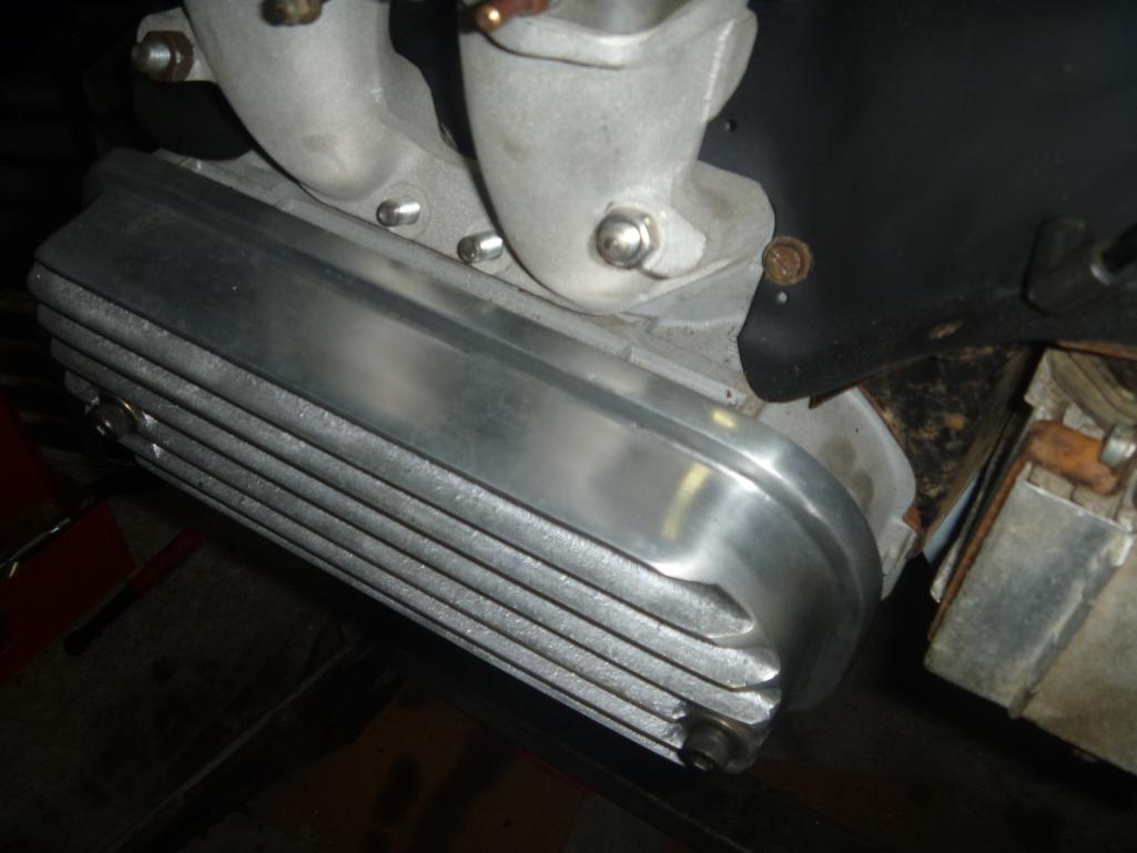
Just about ready to go back into the car. I know that many in the garage deride the bolt on cast CB Perf valve covers, but I am going to try them out. Imagine if I had installed my hexbar linkage for the photos! I am hopeful that the "X-ring" pushrod tube seals help. I also replaced gaskets at the oil pump, and still need to replace the RMS. But I am lowering expectations from a "dry Type IV engine" to a "less wet Type IV engine".
I just really dig these little powerplants, and this one has come out great (again).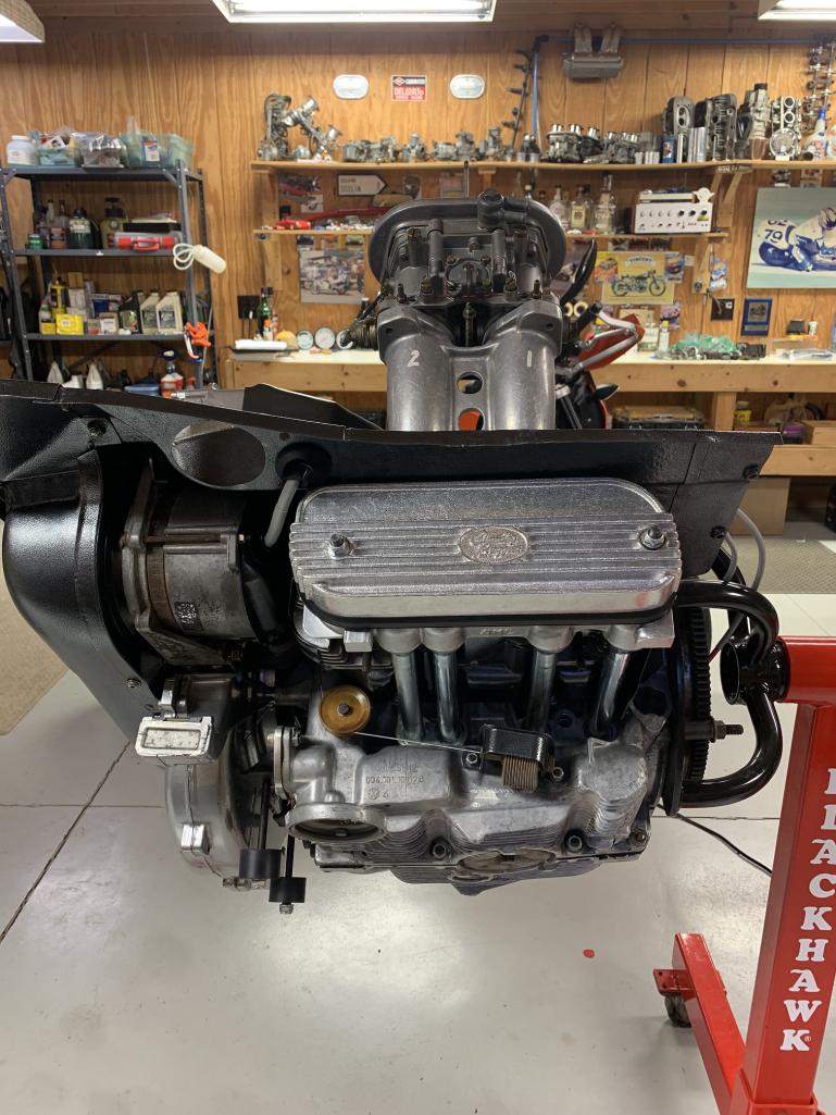
Posted by: sdoolin Mar 10 2024, 11:54 AM
Progress has been slow. Many excuses. But very close to engine installation now. In the pic below, there are 4 wires. This is the "over engine" wiring harness that connects to the relay board with the large(ish) multiplug. Two of them go to the coil (and I even know which side of the coil each goes on), but I am not sure about the other two. One is green and red striped, the other is white. One of them is surely for the oil pressure switch. But, I am not sure which one?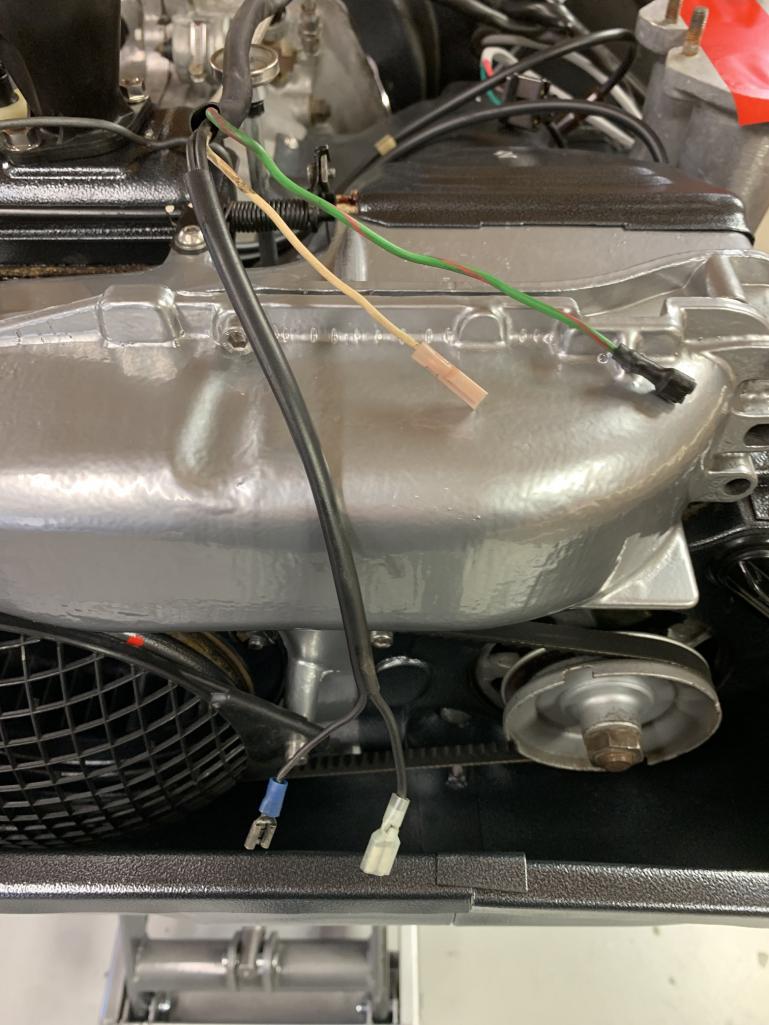
Posted by: technicalninja Mar 10 2024, 01:28 PM
Nicely done!
Really like your "shop"!
Looks cozy and clean.
That top shelf against the wall looks "Damn Interesting". 
Lots of "trophies" there...
Have you thought about a "tuna can"?
https://914werke.com/shop/ols/products/mini-sump/v/OIL-SMP-ASM
Puppy MIGHT save the engine in high G environment.
As it's super easy to install I consider it a MUST HAVE for these engines in a 914.
I like an AccuSump more but those are 10 times the work and cost of a Tuna Can.
I'd run a tuna can on everything, even if I also had an accusump...
Posted by: FlacaProductions Mar 10 2024, 01:36 PM
Green/red is oil pressure sender idiot light.
Posted by: DRPHIL914 Mar 11 2024, 07:23 AM
@http://www.914world.com/bbs2/index.php?showuser=17299
did anyone every address your question about what appeared to be some
oil seepage from the base of the cylinder at the case? I too am about 5-6k miles from my rebuild 2 years ago and now have a very slow drip leak, and i can trace it to there as well, its not my push rod tubes . i am thinking about pulling the motor to check the torque on the head studs , did you do this? i have heard that we may see some stretch of the head bolts. BTW looks like new, very nice.
Phil
Posted by: sdoolin Mar 11 2024, 07:33 AM
Nicely done!
Really like your "shop"!
Looks cozy and clean.
That top shelf against the wall looks "Damn Interesting".
Lots of "trophies" there...
Have you thought about a "tuna can"?
https://914werke.com/shop/ols/products/mini-sump/v/OIL-SMP-ASM
Puppy MIGHT save the engine in high G environment.
As it's super easy to install I consider it a MUST HAVE for these engines in a 914.
I like an AccuSump more but those are 10 times the work and cost of a Tuna Can.
I'd run a tuna can on everything, even if I also had an accusump...
Yeah, there is thousands of dollars worth of "junk" on that top shelf. I have considered a tuna can, but I don't autocross or race this car, and I am worried about a racoon/possum strike. I live in a very rural area.
Posted by: sdoolin Mar 11 2024, 07:37 AM
Green/red is oil pressure sender idiot light.
Thank you Flaca. Anyone know what that white wire is for? The wire appears OE, but the connector does not.
Posted by: sdoolin Mar 11 2024, 07:39 AM
@http://www.914world.com/bbs2/index.php?showuser=17299
did anyone every address your question about what appeared to be some
oil seepage from the base of the cylinder at the case? I too am about 5-6k miles from my rebuild 2 years ago and now have a very slow drip leak, and i can trace it to there as well, its not my push rod tubes . i am thinking about pulling the motor to check the torque on the head studs , did you do this? i have heard that we may see some stretch of the head bolts. BTW looks like new, very nice.
Phil
I never heard from anyone about that leakage, so have moved on. I did re-torque the cylinder head nuts, but none of them moved very much at all.
Posted by: Dave_Darling Mar 11 2024, 08:40 PM
[quote name='sdoolin' date='Mar 11 2024, 06:37 AM' post='3133254
Thank you Flaca. Anyone know what that white wire is for? The wire appears OE, but the connector does not.
[/quote]
The white wire is the power connection for the AAR. It should get +12V any time the fuel pump is running.
--DD
Posted by: sdoolin Mar 12 2024, 08:28 AM
[quote name='Dave_Darling' date='Mar 11 2024, 10:40 PM' post='3133368']
[quote name='sdoolin' date='Mar 11 2024, 06:37 AM' post='3133254
Thank you Flaca. Anyone know what that white wire is for? The wire appears OE, but the connector does not.
[/quote]
The white wire is the power connection for the AAR. It should get +12V any time the fuel pump is running.
--DD
[/quote]
Thank you DD. I am running carbs (love them) so this wire is not needed.
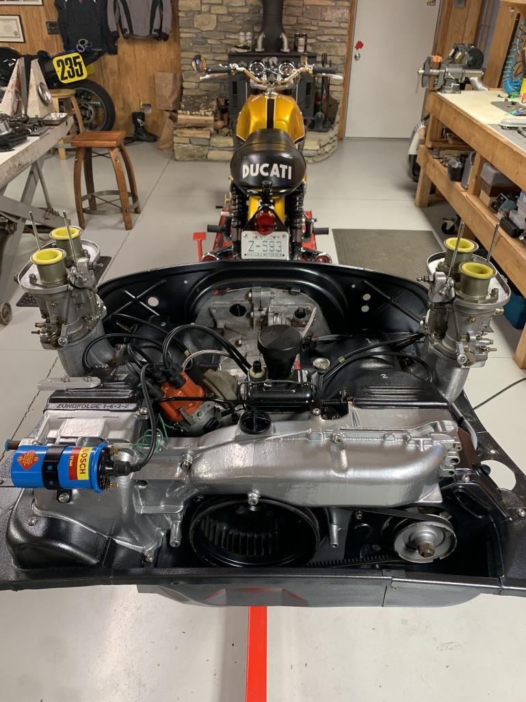
Posted by: sdoolin Mar 27 2024, 11:41 AM
I (finally) have the engine back in the car. I have the heat exchanges and related ducts and heater bits all installed. When I went to install the muffler (it is a Bursch unit), I noticed that things don't line up. The flanges on the muffler are closer together than the flanges on the heat exchangers. This means that the bolt holes on the muffler do not align with the bolt holes on the heat exchangers, they are off by maybe 1/4". I don't remember having this problem the last time I installed the engine.
I am considering loosening the heat exchangers and related bits to give me some "wiggle room" to line up the flanges and bolt holes. I am worried though that this may impair the ability for the heat exchangers to seat solidly and completely in the heads against the copper gaskets?
Anyone else run into this issue? Maybe I have just found an excuse to purchase a new muffler?
Posted by: 930cabman Mar 27 2024, 12:19 PM
I (finally) have the engine back in the car. I have the heat exchanges and related ducts and heater bits all installed. When I went to install the muffler (it is a Bursch unit), I noticed that things don't line up. The flanges on the muffler are closer together than the flanges on the heat exchangers. This means that the bolt holes on the muffler do not align with the bolt holes on the heat exchangers, they are off by maybe 1/4". I don't remember having this problem the last time I installed the engine.
I am considering loosening the heat exchangers and related bits to give me some "wiggle room" to line up the flanges and bolt holes. I am worried though that this may impair the ability for the heat exchangers to seat solidly and completely in the heads against the copper gaskets?
Anyone else run into this issue? Maybe I have just found an excuse to purchase a new muffler?
Yes, I have seen this and have not gotten to the bottom of it. Must be mis alignment at the heat exchanger/cylinder head connection or bent heat exchangers.
Posted by: Dave_Darling Mar 27 2024, 02:03 PM
If the difference is about 1 3/4", it would be a mismatch between the muffler type and exchanger type (1.7/8 versus 2.0). But with a 1/4" difference, it's just things going on a little crooked.
This is why we recommend that the entire exhaust is put on the car loosely before you tighten things up.
If you're worried about the seal on the copper gaskets, pull them out and heat them red-hot to anneal them, making them soft again. Once they cool down, re-install everything and only tighten the fasteners once the pieces are on and lined up.
--DD
Posted by: sdoolin Mar 27 2024, 02:16 PM
If the difference is about 1 3/4", it would be a mismatch between the muffler type and exchanger type (1.7/8 versus 2.0). But with a 1/4" difference, it's just things going on a little crooked.
This is why we recommend that the entire exhaust is put on the car loosely before you tighten things up.
If you're worried about the seal on the copper gaskets, pull them out and heat them red-hot to anneal them, making them soft again. Once they cool down, re-install everything and only tighten the fasteners once the pieces are on and lined up.
--DD
Thanks DD. Not a mismatch, it was all bolted up and running well previous to this project. I'm going to loosen everything up significantly and give it another shot. The copper gaskets are new, and have been annealed. Learned that from many years of bus ownership.
Posted by: bkrantz Mar 27 2024, 09:40 PM
Yup, enough play in the exhaust pipe connections to the heads to skew the flanges for the muffler by at least 1/4". I try to remember not to tighten the nuts on the head studs until I have the muffler bolted up.
Posted by: sdoolin Mar 29 2024, 07:22 AM
Loosened everything up, removed the heater ducts and flappers and wala - muffler went on easily. I'm sure I had to do the same thing last time around, but obviously have forgotten. Now everything on the underside of the car is buttoned up except for a bit of wiring. Next I move to the topside to re-install fuel lines and carbs. Hoping it is a runner again sometime this weekend.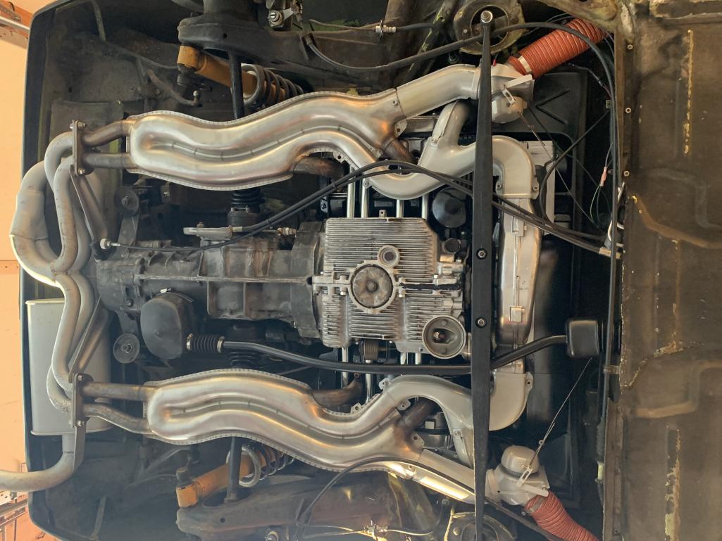
Posted by: GBX0073 Mar 29 2024, 08:30 AM
Great Picture Looking good !
Posted by: technicalninja Mar 29 2024, 09:36 AM
Nice and clean!
Makes it so much easier to see any leaks.
I'm a believer in Tracer Line oil die (and AC die!).
Glows YELLOW under UV light.
Amazon has multiple options for high power UV light sources.
Yellow lens "blue blocker" glasses help bigtime.
Posted by: sdoolin Mar 30 2024, 07:52 AM
Thanks for the compliments in the cleanliness. But I have bad news. Very frustrating, bad news.
Last night I poured 4 quarts of (expensive) Brad Penn 20W50 into the engine. Did not start it, or even crank it over. This morning I inspected for oil leaks and found (expensive) Bad Penn 20W50 coating the right side of the engine, above and on the side of the oil sump. Not good.
It appears to be leaking (a lot) at the case through bolt between cylinders 3 & 4. There is a pronounced, and obvious "stream" of oil from that bolt. Damnit. I also have oil on the case studs/bolts along the bottom of the oils sump. Damnit again.
So, it all has to come out, and I probably will have to split the cases. Which is a MUCH longer project than I had anticipated.
I have built a few of these engines (probably 5, (I owned several busses)), and have followed "best practices" for sealing the cases (according to Jake Raby's assembly video) but I obviously missed something here.
Damnit.
Posted by: technicalninja Mar 30 2024, 08:39 AM
Post a pic of your leak point please.
Really strange to have a static leak that sounds like it's HIGHER than the oil level should be in the sump.
Just looked at my 73 2.0l case...
I found a possible source of the leak!
The lower bolt for the middle camshaft bearing ALSO holds the pick-up and the clearance for this MIGHT be a leak path.
Doesn't look like a good way to seal it internally. Only solution is to add some type of sealing washer under the fastener...
This will be a 13mm headed bolt lower than and between the two pair of push rod tubes, the sump has a half circle depression depression in it to allow access to this fastener.
All of the other studs and bolts have two flat faces on the case completely surrounding the fasteners so these should be much less prone to leak.
I wouldn't take it apart until I really zeroed in on the leak. The lower cam shaft bearing bore bolts MIGHT be under the oil level...
You might be able to stop this leak with an aluminum crush washer
Another option is AC sealing rings-bunch of sizes, and they are crush rings with an O-ring built into the ID (Most!) or in the case of Late model Ford the OD.
I'd go crush ring, flat washer, blue Loctite on threads or class 4 nut if this spot is running a stud in your car.
Might be easy to fix.
"Diag before repair."
Ninja's second most important rule...
First is "There are always exceptions to the rules, rules are for fools, wise men use good judgement first" .
Posted by: technicalninja Mar 30 2024, 08:52 AM
You're going to need a mirror with all the stuff you have installed to even see this pup.
Removing the exhaust system will give you better access...
My wife bought me one of these as a present. I use the piss out of mine.
https://www.harborfreight.com/35-in-digital-inspection-camera-with-micro-sd-card-slot-64170.html
Lots of cheaper options available that use a cell phone.
They will probably work equally well for what you need.
Posted by: sdoolin Mar 30 2024, 09:27 AM
Pic below. Hard to get a good picture but you can see (well, I can see) the leak at the center bolt between the 2 push rod tubes. It is "shiny" with oil at that bolt, and there is a washer behind the bolt head.
Agree Ninja, this seems as if it is above what the oil level would be in the sump. Which is both confusing and frustrating.
For sure the engine has to come out. But not sure (yet) if I gotta split the cases.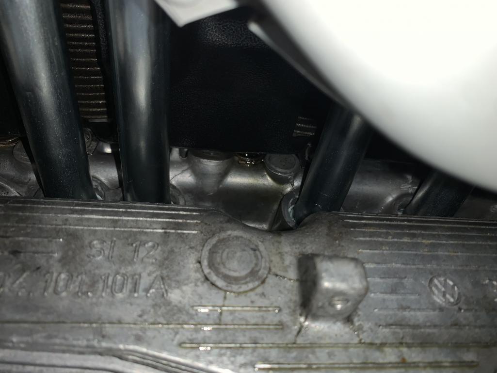
Posted by: technicalninja Mar 30 2024, 10:05 AM
I'd first clean all the oil with B12 carb spray and needle tipped blowgun.
Drain oil into clean pan.
Get the suspect area dry.
Have someone else fill it while I watched that spot like a hawk.
I cannot fathom why that should even see oil much less leak profusely by simply filling the sump.
Posted by: technicalninja Mar 30 2024, 10:42 AM
You're running carbs...
My 75 came with a brand-new progressive Weber 2 bbl kit in the center.
No way I'm going to run that IN THE CAR!
I'm keeping it anyways because it is the ultimate "run engine before installation"
solution out there!
I would have run that after I installed tranny and heat exchangers to verify engine before installation.
The crappy little progressive needs little tuning to make it "run".
I will initially be running dual IDFs on the car.
I'll break in the cam, run the engine till warm, set dist timing, get it to the point I'm happy on the progressive.
Allow to cool, recheck head bolt torque and valve adjustment, change oil (if fresh engine) and then install engine and the real carburetors...
You can do the same with the IDFs. They might be a bit more work than the progressive. If they were close before you took them out, they should be still close enough to run for 20 minutes...
All you need is a 12V power source for distributor and starter and a rudimentary fuel system. A gas can and a simple electric fuel pump is my solution but You can probably supply enough fuel for test bed run via a simple gravity feed from the fuel tank. Put it at least two feet higher than the carbs and create a siphon.
I don't suck on the line anymore. I'll put most of the line into the fuel tank, cap my finger tightly over the open end and pull a column of fuel in the line to start the siphon.
This is not enough flow to test under load but just "on the transmission" does NOT allow for load testing anyways.
Wouldn't take much to be able to run that out of the chassis...
Posted by: ctc911ctc Mar 30 2024, 11:30 AM
I love the Stainless heater boxes, are they new? 
Also, the gray ducting is a nice touch - I powder coated in Black, thought about other colors and chickened out, very nice 
Loosened everything up, removed the heater ducts and flappers and wala - muffler went on easily. I'm sure I had to do the same thing last time around, but obviously have forgotten. Now everything on the underside of the car is buttoned up except for a bit of wiring. Next I move to the topside to re-install fuel lines and carbs. Hoping it is a runner again sometime this weekend.
Posted by: technicalninja Mar 30 2024, 11:34 AM
Forgot to mention a couple of steps I'd do with the "run out of the car" scenario.
Leak down and compression test before the run and then DIRECTLY afterwards.
It's so much easier to do this crap out of the car.
I do the "hot" test as quickly as I could because it will cool fast, especially if your pumping cool air through it or applying cool air at 100 psi into it.
On something I really care about (or a customer is paying big money for) I'll do a "heat cycle" between the comp and leak tests.
I believe the first 90% of break in happens in the first 90 seconds and I commonly achieve comp tests within 1% of each other and leak downs in the high 90s after the first heat cycle.
Most GM engines mount the starter on the block, and you don't even need the transmission bolted up to run the engine. I've fired those on engine stands before.
Posted by: sdoolin Mar 30 2024, 02:13 PM
I'd first clean all the oil with B12 carb spray and needle tipped blowgun.
Drain oil into clean pan.
Get the suspect area dry.
Have someone else fill it while I watched that spot like a hawk.
I cannot fathom why that should even see oil much less leak profusely by simply filling the sump.
Having someone fill it while I watch is a stellar idea. I too cannot fathom why it is leaking at all from that location without even having been run. It don't make no sense.
If you look a couple pages back in this thread you'll see a pic of that part of the engine on the bench before I cleaned it. There is a significant amount of oil. So it has been leaking for some time. I can understand it perhaps leaking after it has been running, or while it is running, but now? No.
Posted by: sdoolin Mar 30 2024, 02:15 PM
Ninja - there's really no reason for me to do a leakdown or compression test at this point. The engine ran strong - quite strong - when I took it out of the car to clean it up and fix oil leaks. No major disassembly was done, so no need for those tests.
Posted by: sdoolin Mar 30 2024, 02:18 PM
I love the Stainless heater boxes, are they new?
Also, the gray ducting is a nice touch - I powder coated in Black, thought about other colors and chickened out, very nice
Loosened everything up, removed the heater ducts and flappers and wala - muffler went on easily. I'm sure I had to do the same thing last time around, but obviously have forgotten. Now everything on the underside of the car is buttoned up except for a bit of wiring. Next I move to the topside to re-install fuel lines and carbs. Hoping it is a runner again sometime this weekend.
The stainless heater boxes are not new, just seriously cleaned. The grey duct work is actually powder coat, and it is "Porsche Grey". It actually has a teeny bit of metal flake in it.
Posted by: r_towle Mar 30 2024, 02:31 PM
You are seeing oil at the case bolt?
I’m not sure there is oil there until you run the engine, which you said you did not?
I can’t remember…those bolts have rubber seals I think.
I need to go look at a case to see the levels for static oil.
Posted by: technicalninja Mar 30 2024, 02:35 PM
Ninja - there's really no reason for me to do a leakdown or compression test at this point. The engine ran strong - quite strong - when I took it out of the car to clean it up and fix oil leaks. No major disassembly was done, so no need for those tests.
Sorry, every single time I've run an engine out of the car it's either a junk yard unit I'm testing OR it's something I've just built. In both instances getting those numbers are really what I'm after.
Now, if you haven't done those tests in a year AND are planning on running it out of chassis I would do it anyway as you have awesome access to the front crank bolt, and I log comp and leak-down over the years on stuff that I really like.
Having recent comp and leak is like having recent blood pressure readings on a human.
I don't trust COLD comp and leak, especially if the engine has been dormant for a while.
Posted by: r_towle Mar 30 2024, 02:39 PM
I dunno…there is no oil at the bolt.
Maybe the cylinder…but the bolts do not appear to ever see oil inside or out unless something else is dripping on them.
I can take more pics of the inside of the case… but it looks like a solid sleeve all the way through.
Attached thumbnail(s)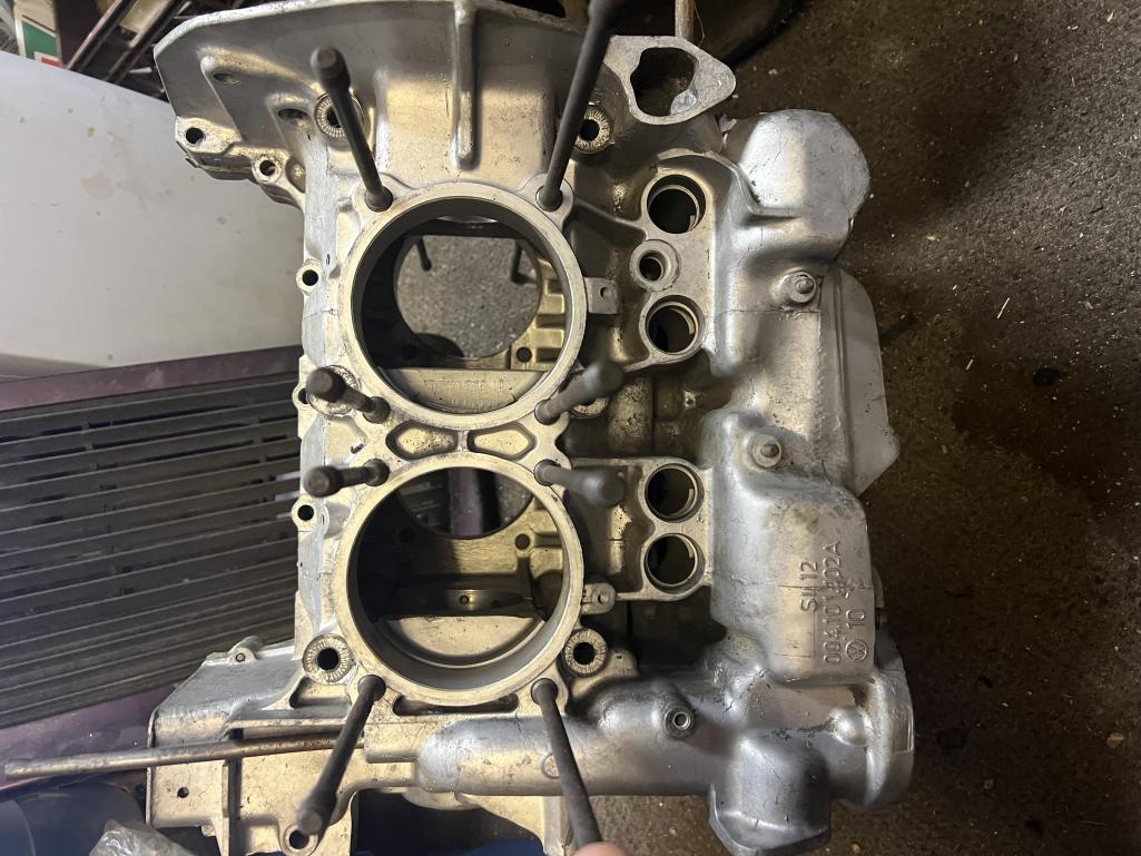
Posted by: r_towle Mar 30 2024, 02:44 PM
Actually a decent pic for my theory.
Look at where you pour oil in.
That whole channel , if the top gasket (simple issue) is not right…at the metal box you place onto the aluminum case, was to leak…
Oil could , in theory, travel down to the middle of the motor to drip.
Posted by: technicalninja Mar 30 2024, 02:58 PM
You are seeing oil at the case bolt?
I’m not sure there is oil there until you run the engine, which you said you did not?
I can’t remember…those bolts have rubber seals I think.
I need to go look at a case to see the levels for static oil.
I did...
the only holes level with or below the windage tray are the three lower cam journal fasteners on the passenger side case.
The front and the back ones fully close as they are at the case mating surface.
This surface is cut back on the driver's case side to provide room for the hanger for the oil pump pick-up at the middle bolt and MIGHT be a path for the leak he's describing.
I don't know how high 4 qts. will fill a T4 sump.
I'm assuming the level is below the windage tray.
Posted by: bkrantz Mar 30 2024, 07:49 PM
Just speculating...
If you added 4 qts but have not run the engine, the level in the sump could be higher than normal. And just might reach that small bolt (which provides a clamp for the center cam bearing, and retains the stud for the strainer). If that bolt head is not sealed, it could leak. But would have to be very unsealed to leak as quickly as you reported.
Can you see if the bolt is tight?
Attached thumbnail(s)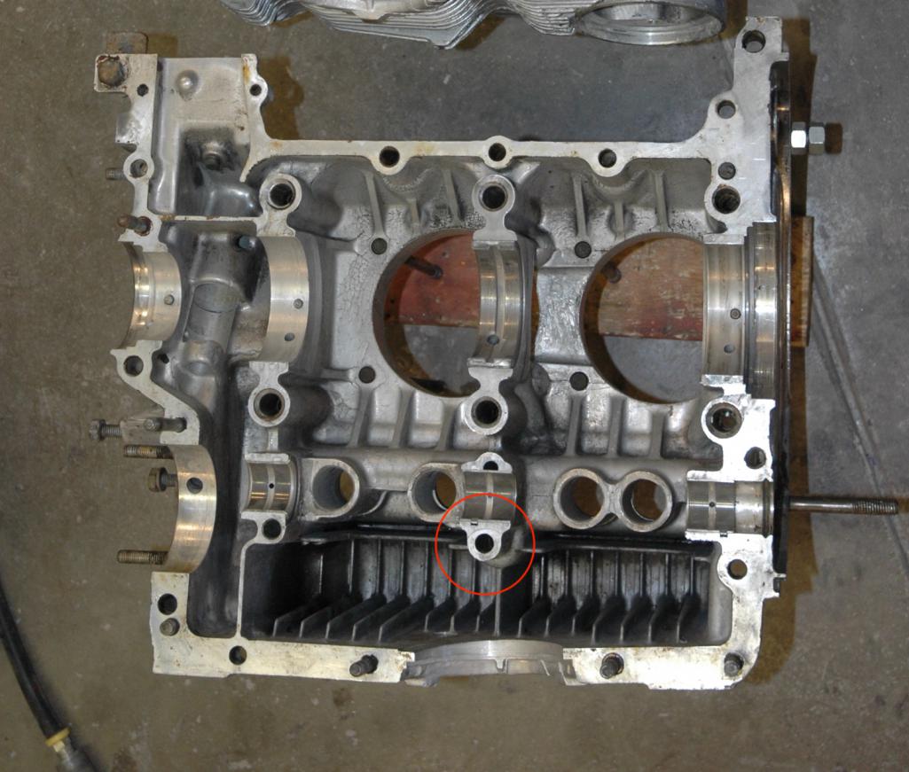
Posted by: technicalninja Mar 30 2024, 07:59 PM
That's the only path I can see being possible.
Posted by: sdoolin Apr 1 2024, 09:44 AM
Just speculating...
If you added 4 qts but have not run the engine, the level in the sump could be higher than normal. And just might reach that small bolt (which provides a clamp for the center cam bearing, and retains the stud for the strainer). If that bolt head is not sealed, it could leak. But would have to be very unsealed to leak as quickly as you reported.
Can you see if the bolt is tight?
Thanks for the thoughts and replies. My leak is from the case through bolt which is located just above the red circled hole in the image above. Which (again) is baffling. I do recall that when I re-assembled the cases (4 years ago) I got things bolted together and realized I had not installed the oil pickup. So I had to quickly split the cases again, install the oil pickup, and the re-tighten things. Perhaps this is the ultimate source of this leak? I still just don't get how oil is here.
I'll see if I can get a wrench or a socket on that bolt, but it is pretty unlikely with everything all bolted up. It hides behind the lower engine tins under the cylinders.
Posted by: Jack Standz Apr 1 2024, 10:37 AM
Sorry to have to even mention it, but the Type IV Syndrome can cause that bolt to never get tight and cause it to leak.
Like in this tread:
https://www.thesamba.com/vw/forum/viewtopic.php?t=612973
Edit:
Sorry, was going by the hole/fastener in the red circle, which is not the hole in question. Best guess is that the motor has too much oil and it's above the level of the hole that's leaking. What's the oil level on the dipstick?
Posted by: sdoolin Apr 1 2024, 11:41 AM
Sorry to have to even mention it, but the Type IV Syndrome can cause that bolt to never get tight and cause it to leak.
Like in this tread:
https://www.thesamba.com/vw/forum/viewtopic.php?t=612973
Edit:
Sorry, was going by the hole/fastener in the red circle, which is not the hole in question. Best guess is that the motor has too much oil and it's above the level of the hole that's leaking. What's the oil level on the dipstick?
Oil level on the dipstick is spot-on.
Posted by: Dave_Darling Apr 3 2024, 11:47 PM
My guess is that someone spilled oil on top of the engine, and it made its way down and out. It'll look like it's coming out of all kinds of strange places.
.... Not that I've done that myself.
.... more than once.
--DD
Posted by: r_towle Apr 4 2024, 05:36 PM
I wonder…..
Could push rod tubes be threaded into the case with a slip joint in the middle to account for expansion and retraction?
Or, did Foley solve this?
Posted by: sdoolin Apr 23 2024, 07:09 AM
Engine is back out of the car and on the bench. Car is down for the summer now. Damnit. I just couldn't stand the thought of a continued (preventable) oil leak.
Updates to this thread as they become meaningful (or fun).
Posted by: bkrantz Apr 23 2024, 08:00 PM
I feel your pain. Start with a deep breath. Or three.
Posted by: sdoolin Apr 24 2024, 09:14 AM
Started disassembly last night - halfheartedly. This engine does not have a windage tray - it came out of a bus that I owned for decades. Do I "need" a windage tray?
If yes, where do I source one?
Posted by: Jack Standz Apr 24 2024, 10:52 AM
That doesn't look like a bus case. It makes sense to run a windage tray & you can place an add here because someone probably has one they're willing to part with.
Powered by Invision Power Board (http://www.invisionboard.com)
© Invision Power Services (http://www.invisionpower.com)