Printable Version of Topic
Click here to view this topic in its original format
914World.com _ 914World Garage _ (UN)bypassing a fuel pump relay..
Posted by: DougC Oct 19 2005, 09:24 AM
PO of my car ('73 w/D-jet) had installed carbs and had the fuel pump under the gas tank. The FP was wired directly to the #8 fuse on the panel, and the ground attached at some point above the fuse panel I believe. Anyway I want to go back to having the FP run through the relay on the board in the engine compartment since I'll be using fuel injection. So I disconnected the wire going to #8 fuse (+ FP wire) and made a connecting wire to the Black/Red wire at the front right hand side of the engine compartment which was originally used for the FP. This didn't work to energize the FP at all, nothing when I turned the key and I'm not sure why. Can anyone tell me what I'm missing? There is a FP relay in the board that I believe is good.
Doug C
Posted by: SirAndy Oct 19 2005, 10:07 AM
| QUOTE (DougC @ Oct 19 2005, 08:24 AM) |
| I'm not sure why |
got the brain hooked up? the relay is controlled by the stock FI-Brain ...
 Andy
Andy
Posted by: ClayPerrine Oct 19 2005, 10:13 AM
You don't have a computer to energize the fuel pump relay.
Remember the diagram of the relay board I was showing you? We have to add a wire to the 4 pin connector to turn on the fuel pump. It should come from the switch under the air flow meter. 
Take out relay #75. Make sure that pins #30 and #85 have 12v.
If both have 12v, jumper pins 30 and 87, and see if the pump runs.
If that works, put the relay back in and ground the front left pin on the 4 pin connector on the relay board (numbered III on the diagram). The pump should run.
Now we need to build the harness for the engine.
Posted by: DougC Oct 19 2005, 10:41 AM
If that works, put the relay back in and ground the front left pin on the 4 pin connector on the relay board (numbered III on the diagram). The pump should run.
OK, if those have 12v and I do ground the "III" on the D-jet connector should I then connect the "I" from that connector to the switch under the air meter since it's powered? I already have a loose wire there from that switch that's not hooked to anything.
Doug C
Posted by: ClayPerrine Oct 19 2005, 11:27 AM
Doug,
It's not that simple. You have to have a relay in the start circuit to turn on the fuel pump when the engine is cranking, otherwise it will NEVER start. Then when the engine fires up, the switch in the air flow meter takes over and keeps the fuel pump relay grounded.
Speaking of running, did you get it running yet? I will be available Saturday if you want some help.
Posted by: ClayPerrine Oct 19 2005, 11:55 AM
Here's a wiring diagram for CIS on a 914.
Attached thumbnail(s)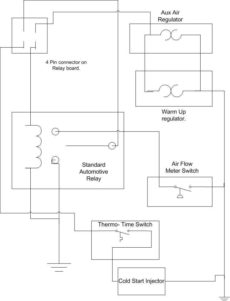
Posted by: ClayPerrine Oct 19 2005, 12:09 PM
| QUOTE (lapuwali @ Oct 19 2005, 12:01 PM) |
| Clay, that diagram doesn't look right to me. The air meter switch will short straight to ground when it closes. I'd move the air-meter lead over to the relay coil ground instead. |
You are correct, the air flow meter switch will provide a ground to the relay. But ath is what it is supposed to do. The relay in the diagram provides ground for the factory fuel pump relay on the relay board. When the diagram's relay is not energized, the air flow meter switch provides ground for Pin III on the relay board. When the car is cranking, power is supplied to pins II and IV on the 4 pin connector. Pin IV provides power to the thermo time switch and cold start injector, and pin II provides power to the diagrams' relay. The diagram's relay closes, and it bypasses the air flow meter switch and provides ground for the fuel pump relay.
Now does that make sense?????

Posted by: lapuwali Oct 19 2005, 12:15 PM
I looked again, you're right. Duh on my part. Much more convoluted than I imagined, but this should work fine.
Doug, this is very similar to what I PM'd you about.
Posted by: ClayPerrine Oct 19 2005, 12:20 PM
You could leave the relay out, but the car would never start.... 
Gotta have power to the fuel pump during cranking.
Doug, if you get me approximate measurements to the components on your engine from the 4 pin connector on the relay board, I will build the harness for you.
Make sure you add about 8 to 10 inches to every measurement for strain relief.
Posted by: DougC Oct 19 2005, 12:39 PM
Clay - I will take those measurements this evening. But just confused on the whole harness thing. I mean I do have new ground wires going to the back of the alt (D-). Basically with what you're talking about building won't require removing the complete Intake/CIS unit AGAIN will it? I feel like I've done that more than I care to remember and I've drawn up a schematic and taken good notes of what everything in the wiring harness goes to. So, is the new harness just to controll the FP and relay? Oh, and no I haven't been able to get the engine started any more than it did the other day, which was a few seconds. Please pencil me in for Saturday help if you don't mind - I owe you big time!
Doug C
Powered by Invision Power Board (http://www.invisionboard.com)
© Invision Power Services (http://www.invisionpower.com)