Printable Version of Topic
Click here to view this topic in its original format
914World.com _ 914World Garage _ There sure are a lot of parts in a 901 box
Posted by: DNHunt Nov 5 2005, 08:30 AM
Lots and lots of parts that are hard to keep track of. And lots of cleaning.
Attached image(s)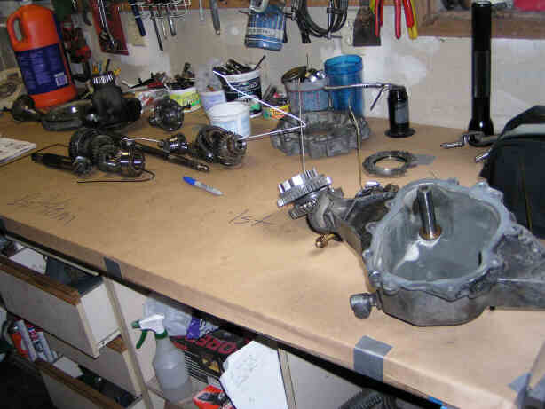
Posted by: DNHunt Nov 5 2005, 08:31 AM
What have I done?
Attached image(s)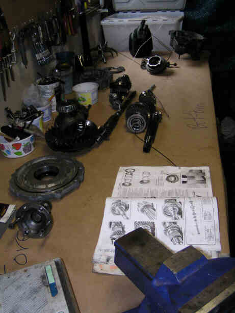
Posted by: DNHunt Nov 5 2005, 08:37 AM
This started as a grind in 1st and 2nd. I used Bondo's and Red Beards info to get it apart. One thing I would advise is take it apart before you order parts cause it may be worse than you think and surprises are expensive. I invested in some syncros, dogteeth, gaskets and such before I found this. The price tag just went up.
Attached image(s)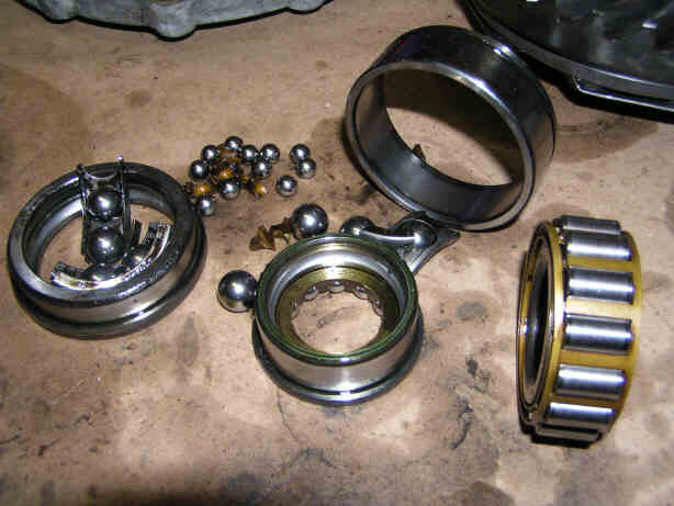
Posted by: DNHunt Nov 5 2005, 08:44 AM
So here I go. The race for the new big bearing on the pinion shaft needed to be installed in the case. It is positioned by a couple of snap rings. The reason I went ahead with this tranny was because this race is still a press fit into this case. I used piston ring pliers to expand this snap ring and istall it on the race. I haven't reistalled the ring gear and diff yet cause I wanted to be able to verify if the race was seated.
Attached image(s)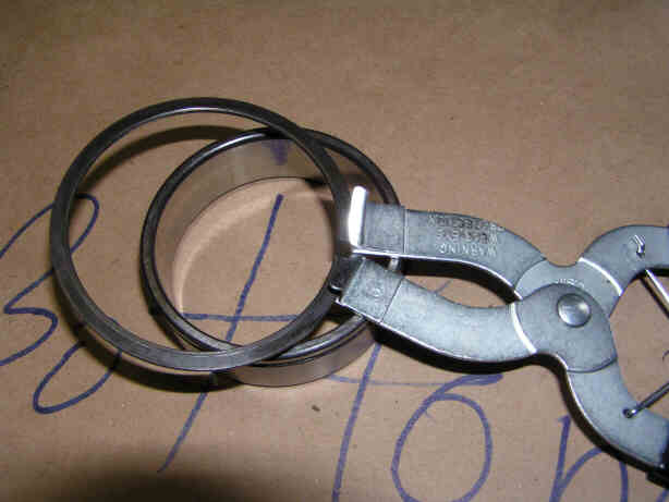
Posted by: DNHunt Nov 5 2005, 08:46 AM
One snap ring on
Attached image(s)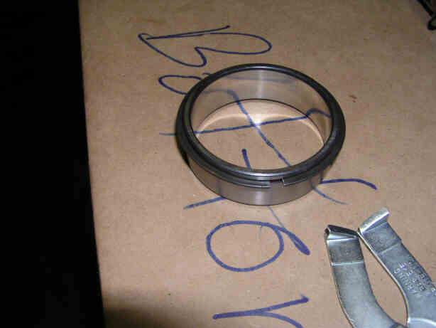
Posted by: DNHunt Nov 5 2005, 08:50 AM
Seating the race. I used a piece of PVC pipe about the same diameter to drive the race in. I tapped very lightly, slow going. The case wouldn't fit in the oven and the wife was on a terror last night so I couldn't heat it. 
Attached image(s)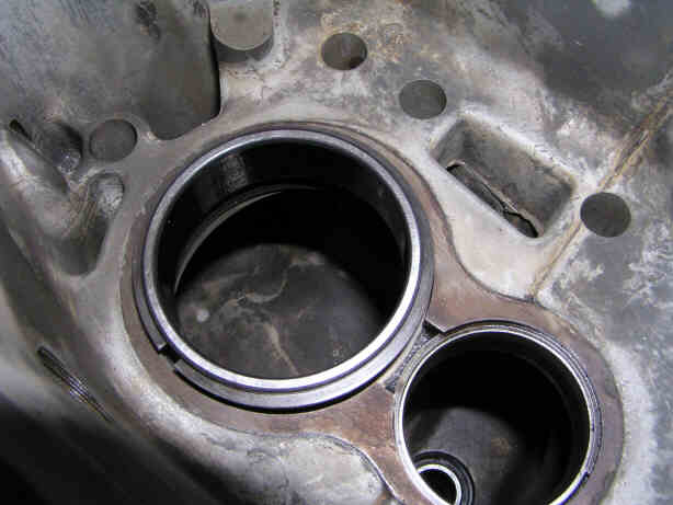
Posted by: DNHunt Nov 5 2005, 08:59 AM
Here is the race seated and the second snap ring installed. The 1st ring contrats against the bearing race. The second ring expands against the case. These 2 rings on the race trap the bearing race in position. Pretty cool.
Attached image(s)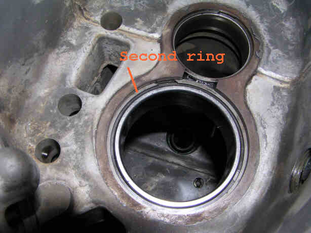
Posted by: DNHunt Nov 5 2005, 09:02 AM
New seals. I sure love PVC pipe
Attached image(s)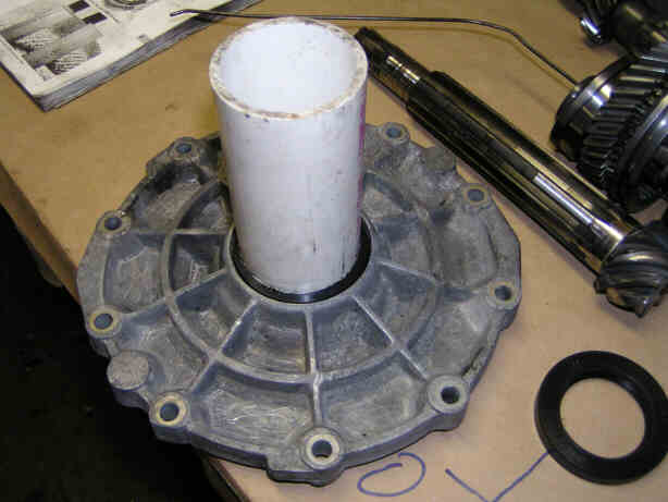
Posted by: Bleyseng Nov 5 2005, 09:04 AM
Ran it low on oil huh, Dave.
Watch how you install the gears back onto the shafts, they should be prefectly aligned with each other. They have a shoulder on them so they face only one way (look in the book or do you have the workshop manual?).
Aligning the shift rods is tricky so follow the books carefully.
Looks good!
Posted by: DNHunt Nov 5 2005, 09:04 AM
Time to install this after a few squirts of gear lube and a little lube in the bearings
Attached image(s)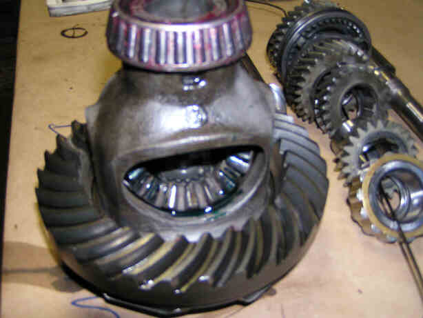
Posted by: DNHunt Nov 5 2005, 09:06 AM
Installed
Attached image(s)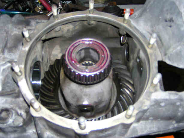
Posted by: DNHunt Nov 5 2005, 09:09 AM
I installed a new O ring with a little gear lube and torqued down the cover
Attached image(s)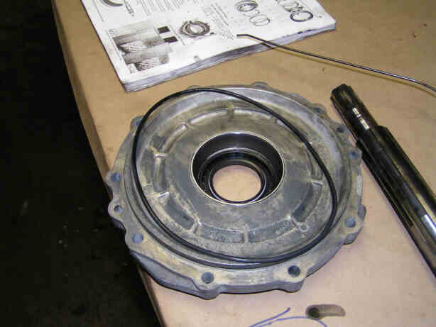
Posted by: DNHunt Nov 5 2005, 09:13 AM
Onto the gear stack. I needed to replace dogteeth on 2nd gear. I put the gear in a vice and tap off the dogteeth with a mallet amd chisel. It ruins the chisel but, the gear is fine.
Attached image(s)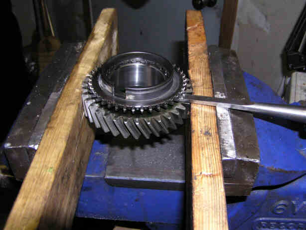
Posted by: Verruckt Nov 5 2005, 09:14 AM
| QUOTE (DNHunt @ Nov 5 2005, 08:31 AM) |
| What have I done? |
What manual is that, and where did you get it? I'm looking for one of those. I have a few that I'm going to be digging into over the winter months.
Posted by: DNHunt Nov 5 2005, 09:21 AM
Here's the new dogteeth installed on the gear. 2nd gets a new syncro, new dogteeth and the 4th - 5th slider. 3rd gets a new syncro.
Attached image(s)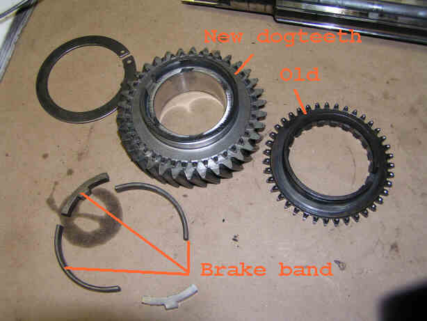
Posted by: DNHunt Nov 5 2005, 09:27 AM
I put the brake band stops (I can't remember if they are called stops or blocks) on the dogteeth of 2nd gear.
Attached image(s)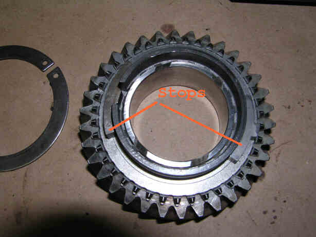
Posted by: DNHunt Nov 5 2005, 09:31 AM
Brake bands installed. There are 2 on 2nd through 5 th. 1 on 1st.
Attached image(s)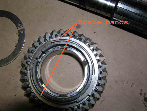
Posted by: DNHunt Nov 5 2005, 09:37 AM
This picture shows the new syncro installed and it's relationship with the brake band blocks. Nice sharp new dogteeth 
Attached image(s)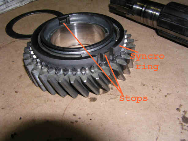
Posted by: DNHunt Nov 5 2005, 09:39 AM
I installed the snap ring (a bitch) to finsh the assembly of 2nd gear.
Attached image(s)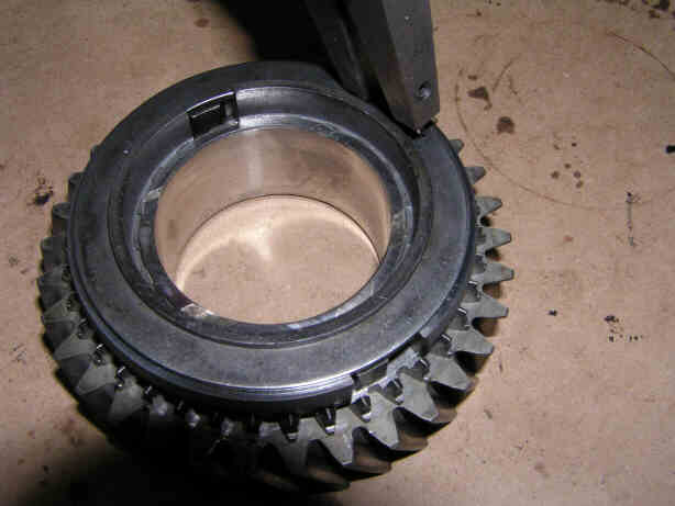
Posted by: DNHunt Nov 5 2005, 09:53 AM
I had a hell of a time with the snap rings slipping off of my pliers so I cut off some 6lb finishing nails and filed the heads down until they fit in the holes in the rings. The heads kepth the rings from shooting off.
Attached image(s)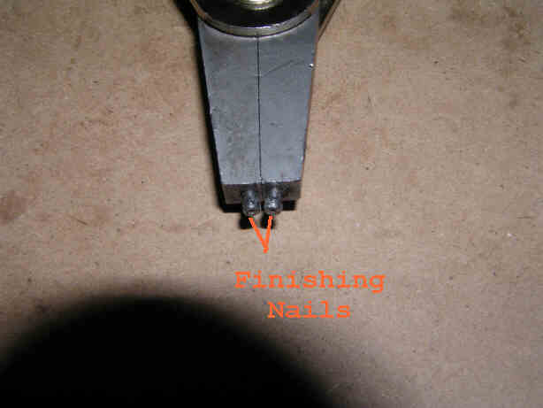
Posted by: rdauenhauer Nov 5 2005, 11:15 AM
Dude I just start this myself!
Planned on just pulling one apart so I could clean the case, and inspect the internals at same time.
Now Im VERY affraid, and In awe at the same time.
Not sure I have the skills (or patience  ) for this.
Posted by: Headrage Nov 5 2005, 11:27 AM
Nice work!!!
Posted by: Tom Perso Nov 5 2005, 12:17 PM
Nice trick with the 6 penny nails. I HATE snap rings...
Tom
Posted by: J P Stein Nov 5 2005, 12:40 PM
Ah, good....Dave is doing this.
I have an AX tomorrow then it's....ta da!...."winter project"
time. (sometimes stretching into spring  )
)
Amongst the items to be covered is installing a 'B' first gear.
Since Dave will soon be an expert, he can come down & bail me out of the mess I'll make.
If I work a bunch of OT, maybe a 904 mainshaft & a new 2nd 
If I hit the lotto, an LSD 
Posted by: DNHunt Nov 5 2005, 04:20 PM
Onto the pinion shaft. Just got back from a soccer game. This is the roller bearing at the flywheel end of the pinion shaft. It goes in the race I installed in the case. I drove it on with a piece of galvanized pipe on the race
Attached image(s)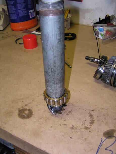
Posted by: DNHunt Nov 5 2005, 04:24 PM
Next come the shims that help set pinion depth.
Attached image(s)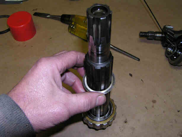
Posted by: DNHunt Nov 5 2005, 04:26 PM
I had 3 shims in this box. I think there can be different numbers unlike the endplay shims on a type 4. The washer that goes next is on the bench
Attached image(s)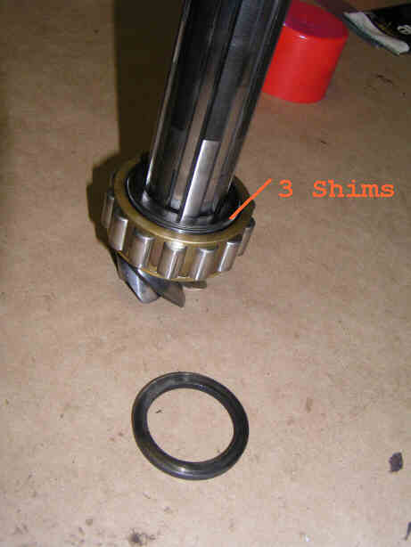
Posted by: DNHunt Nov 5 2005, 04:31 PM
After that washer is 5th gear. One of the hard things is keeping everything in order. I used coat hangers to run through the center of everthing. Then I could just pull one thing off at a time. it worked really wel except for 1 set of gears. Watch and see if you can find the mistake. I'll let you know when you should be able to see it
Attached image(s)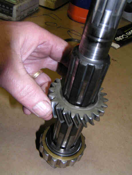
Posted by: DNHunt Nov 5 2005, 04:36 PM
There is a ridge on one side of 4th and 5th gear that butts up to the spacing collar between them. You can see it on the top of the gear near the splined shaft. Ah sh*t off to a wedding reception. Yes honey 
Attached image(s)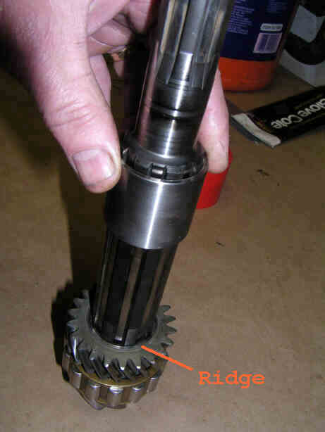
Posted by: DNHunt Nov 5 2005, 04:49 PM
4th gear with the ridge down facing the spacing collar
Attached image(s)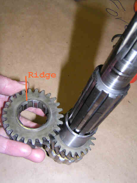
Posted by: DNHunt Nov 5 2005, 04:50 PM
Another washer
Attached image(s)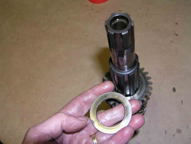
Posted by: DNHunt Nov 5 2005, 04:52 PM
Next comes the race for the roller bearing for the 3rd gear assembly.
Attached image(s)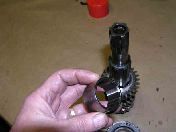
Posted by: DNHunt Nov 5 2005, 08:30 PM
Roller bearing for 3rd gear goes on next. It just slips over the race
Attached image(s)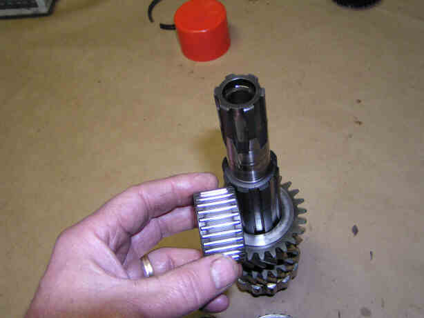
Posted by: DNHunt Nov 5 2005, 09:05 PM
Here's the roller bearing on the race ready to install the 3rd gear assembly (gear, brake band and blocks, dogteeth, syncro, and snap ring). All of the gears go on the shafts like this.
Attached image(s)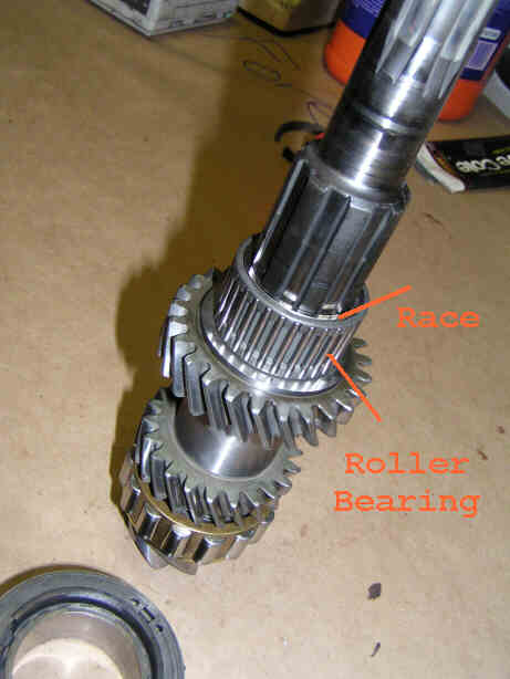
Posted by: DNHunt Nov 5 2005, 09:07 PM
3rd gear assembly goes over the race and roller bearing with the dogteeth and snap ring up.
Attached image(s)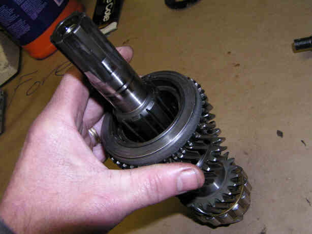
Posted by: DNHunt Nov 5 2005, 09:09 PM
Next is the slider hub for the 2nd and 3rd slider. Don't worry about which way it goes. There is no top or bottom so ram it home. 
Attached image(s)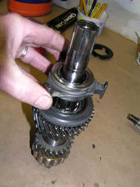
Posted by: DNHunt Nov 5 2005, 09:10 PM
2nd, 3rd slider fits on its hub. You can't miss with this.
Attached image(s)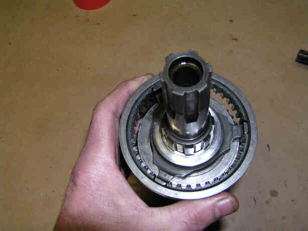
Posted by: DNHunt Nov 5 2005, 09:13 PM
Next the 2nd gear race, roller bearing and gear assembly go on the shaft. The dogteeth point down toward the slider
Attached image(s)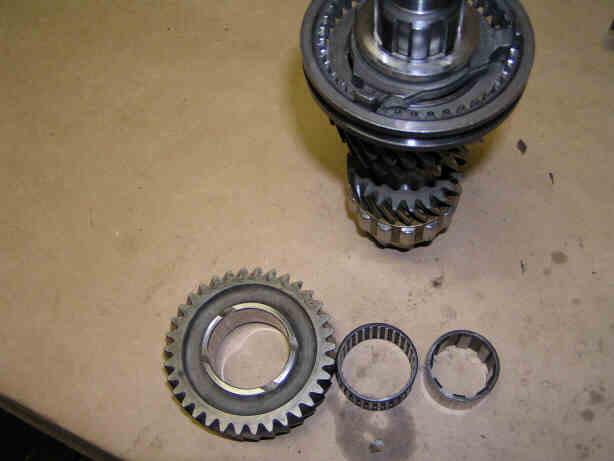
Posted by: DNHunt Nov 5 2005, 09:16 PM
Another cone washer goes on next. You have to keep them in order cause they are all just a little different. 2nd gear is on the pinion shaft with the dogteeth pointed toward the slider (in this case down away from the camera).
Attached image(s)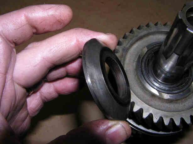
Posted by: DNHunt Nov 5 2005, 09:20 PM
Finally, the race for the ball bearing in the intermediate plate. Once this is tapped down the pinion shaft is ready to go in the intermediate plate.
Attached image(s)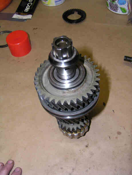
Posted by: DNHunt Nov 5 2005, 09:40 PM
The finished pinion shaft assembly
Attached image(s)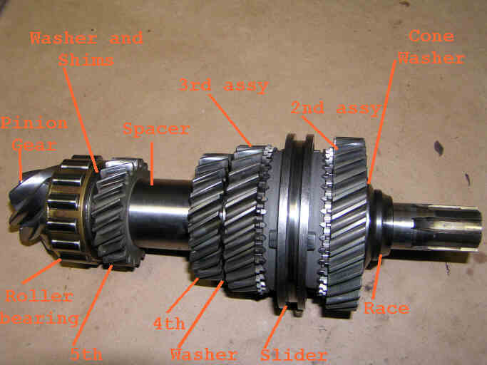
Posted by: bd1308 Nov 5 2005, 09:52 PM
wow. so 2nd and 3rd are the only gears with a slider...?
1st and reverse is on the other side of the intermediate plate right?
b
Posted by: DNHunt Nov 6 2005, 06:12 AM
Time to assemble the drive shaft. 2nd gear on the usual box is ground as part of the drive shaft so, so I got a freebie cause there is no way to screw it up. The first thing I put on was the race for the double ball bearing in the intermediate plate. It goes on the side of 2nd gear with the short part of the shaft.
Attached image(s)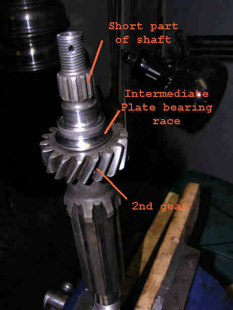
Posted by: DNHunt Nov 6 2005, 06:14 AM
Now I turned the shaft over so i was putting parts on the long end of the drive shaft. 3rd gear next
Attached image(s)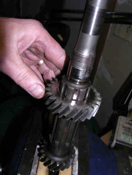
Posted by: DNHunt Nov 6 2005, 06:15 AM
Next goes a flat washer
Attached image(s)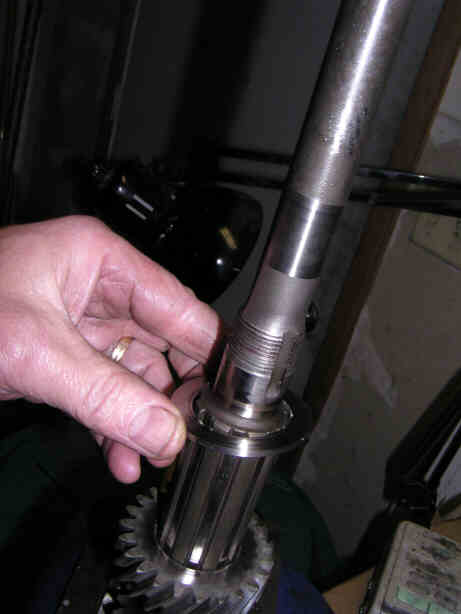
Posted by: DNHunt Nov 6 2005, 06:20 AM
Here's the beginning of the one mistake I made (the one I caught at least). Next goes the 4th gear assembly. It goes on over a race and roller bearing just like 2nd and 3rd assemblies on the pinion shaft. Always, dogteeth toward the slider
Attached image(s)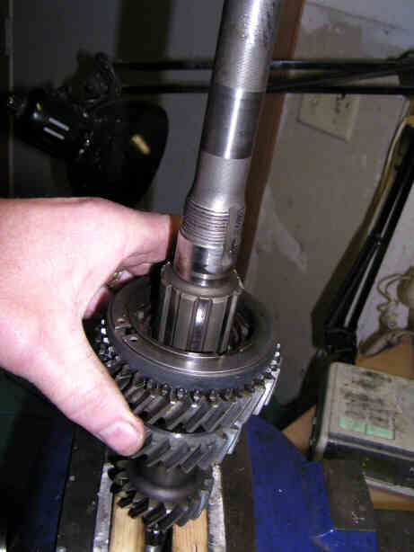
Posted by: DNHunt Nov 6 2005, 06:23 AM
4th, 5th slider hub. There is no right or wrong side, just slide it on.
Attached image(s)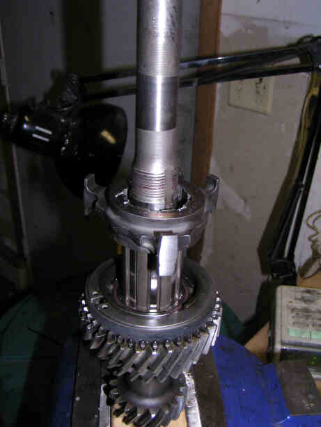
Posted by: DNHunt Nov 6 2005, 06:31 AM
4th, 5th slider. I swapped this slider with the 2nd, 3rd slider because the 2nd, 3rd slider had a touch of wear and 4th and 5th don't get used as much as 2nd and 3rd.
Attached image(s)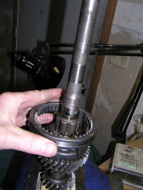
Posted by: DNHunt Nov 6 2005, 06:33 AM
I'm still continuing in my ignorance. 5th gear assembly goes on with the dogteeth down toward the slider.
Attached image(s)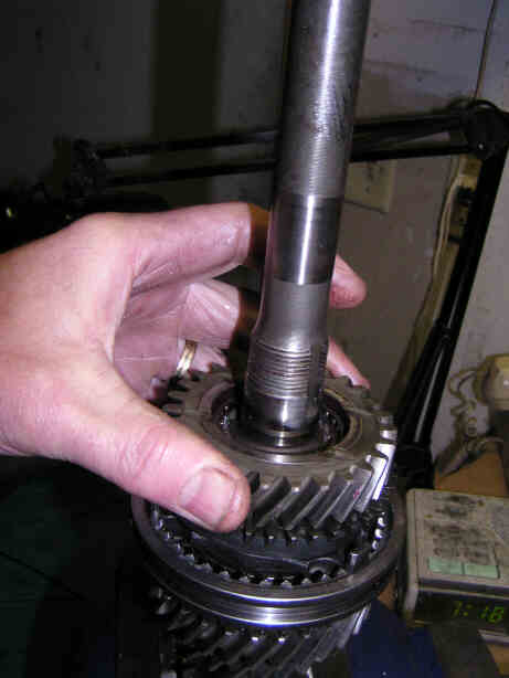
Posted by: DNHunt Nov 6 2005, 06:34 AM
Cone washer
Attached image(s)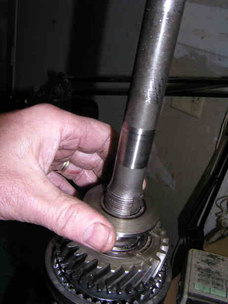
Posted by: DNHunt Nov 6 2005, 06:37 AM
Next goes the smaller roller bearing and a locking plate. The tab goes in the slot pointed down to go under the bearing.
Attached image(s)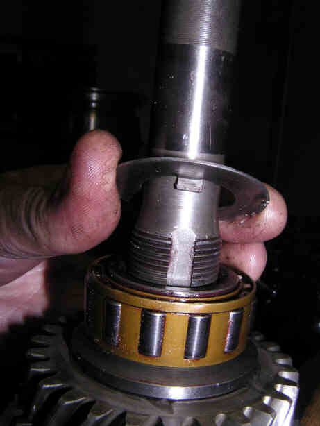
Posted by: DNHunt Nov 6 2005, 06:40 AM
Tighten the nut down to 80 lbs and bend up 1 edge of the locking plate and the drive shaft is ready. I still haven't caught my mistake. Anyone that has been in one of these boxes should see it now.
Attached image(s)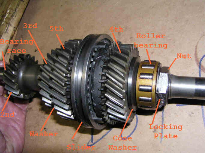
Posted by: sj914 Nov 6 2005, 06:46 AM
4th and 5th gear are in the wrong order?
How did you torque that nut to 80ft/lbs.?
Posted by: DNHunt Nov 6 2005, 07:01 AM
You are RiIGHT. It won't go in the intermediate plate like that. I guessed. I did mark the shaft and nut so I got them to the same spot.
Posted by: DNHunt Nov 6 2005, 07:03 AM
Ah, the intermediate plate. I installed the bearing races (the whole bearing for the pinion shaft).
Attached image(s)
Posted by: DNHunt Nov 6 2005, 07:05 AM
Next comes the spacer that goes under the bearing retainer plate.
Attached image(s)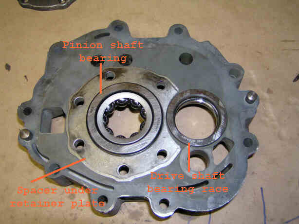
Posted by: DNHunt Nov 6 2005, 07:06 AM
The bearing retainer plate
Attached image(s)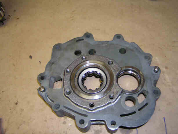
Posted by: DNHunt Nov 6 2005, 07:07 AM
Here is another use for the CV joint tool. 8mm 12point.
Attached image(s)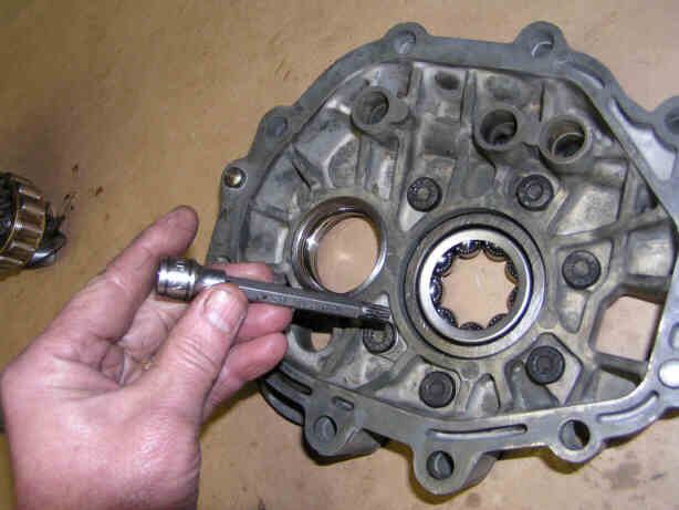
Posted by: DNHunt Nov 6 2005, 07:08 AM
Torqued to 15-17 lb ft. I had a heck of a time figuring out how to steady the intermediate plate while I torqued it. I finally put a couple of 8mm bolts in my vice and put the plate over them.
Attached image(s)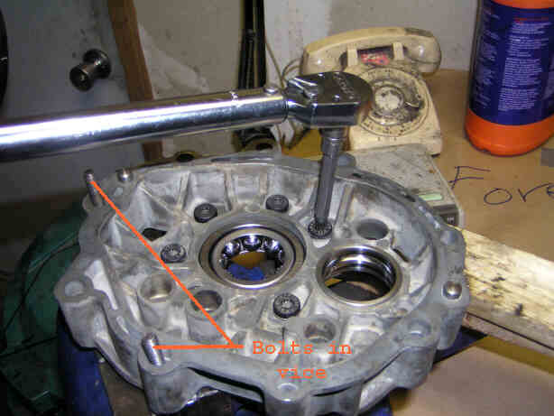
Posted by: DNHunt Nov 6 2005, 07:15 AM
I'm ready to drive the race down the pinion shaft
Attached image(s)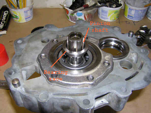
Posted by: DNHunt Nov 6 2005, 07:16 AM
Pinion and drive shafts installed in the intermediate plate and ready for 1st gear.
Attached image(s)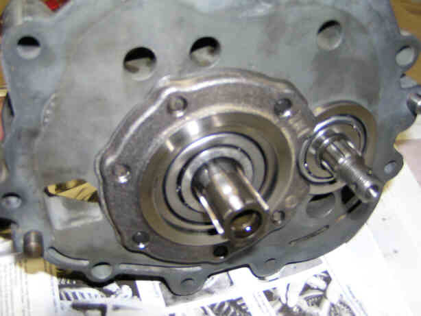
Posted by: DNHunt Nov 6 2005, 07:48 AM
1st gear on the drive shaft is the gear then a washer, a castle nut secured with a roll pin. The flat surface of the gear faces away from the bearing.
Attached image(s)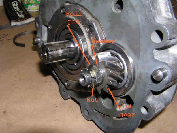
Posted by: DNHunt Nov 6 2005, 07:49 AM
The pinion shaft ready for the 1st gear assembly
Attached image(s)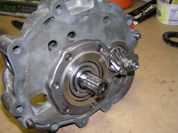
Posted by: DNHunt Nov 6 2005, 08:02 AM
A washer goes on the pinion shaft first
Attached image(s)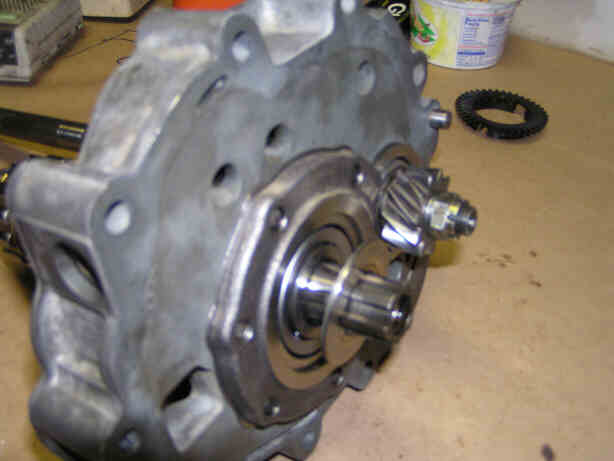
Posted by: DNHunt Nov 6 2005, 08:03 AM
Just like the other gear assemblies a race goes on the shaft first
Attached image(s)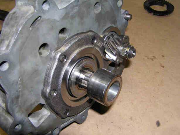
Posted by: DNHunt Nov 6 2005, 08:06 AM
Then the roller bearing
Attached image(s)
Posted by: DNHunt Nov 6 2005, 08:07 AM
Then the 1st gear assembly. Sorry about the fuzzy picture
Attached image(s)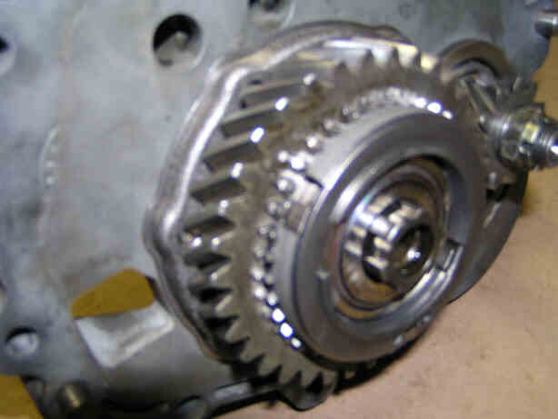
Posted by: DNHunt Nov 6 2005, 08:09 AM
Next is the slider hub.
Attached image(s)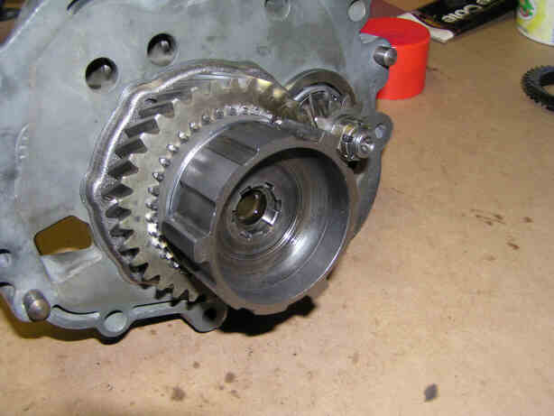
Posted by: DNHunt Nov 6 2005, 08:12 AM
I got this slider used and it is in really good shape. The teeth are sharp and there is ver little wear
Attached image(s)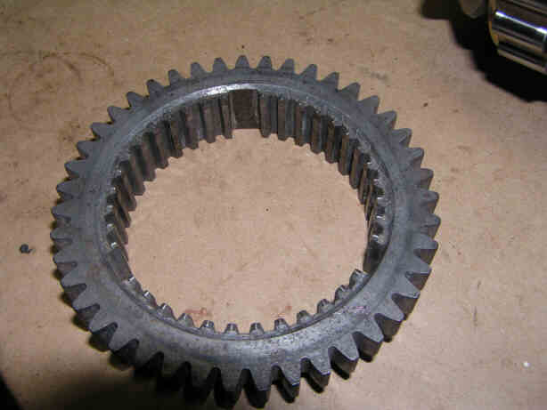
Posted by: DNHunt Nov 6 2005, 08:13 AM
The slider goes on with the teeth facing the first gear assembly. The bolt holds it all together.
Attached image(s)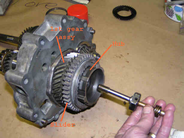
Posted by: qa1142 Nov 6 2005, 09:15 AM
Wow!
Move this to classics once this is done.
Posted by: DNHunt Nov 6 2005, 12:33 PM
Shift forks, shafts and detents. I really like this part. People sure are clever.
I borrowed this pic from Royce. Thanks man. It shows the parts. The shift forks are not shown.
A couple of things. The springs and balls on the right fit into a tube in the intermediate plate and you see the plug on the bottom of the transmission. They serve to center the transmission in neutral. They also prevent selection of 2 gears at once. You feel these somewhat (along with the compression of the syncro rings) when the shifter passes through neutral and especially when you select reverse. It works most of the time. I used a little all purpose grease to coat the parts as they can escape through the shift rod holes in the intermediate plate (and grease is usually good). I spent a while looking for 1 of the balls on the garage floor.
The notch in the picture positions one of the shift forks. An 8mm bolt passes through the shift fork and engages this notch then threds into the other side of the shift fork. This notch is larger than the 8nn bolt so it allows the shift forlk some adjustment on the shaft. Tightening the bolt then clampd the shift fork to the shift rod.
Ah, fork it, I can't explain it. Look at the pictures
Attached image(s)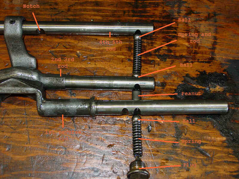
Posted by: DNHunt Nov 6 2005, 12:35 PM
Start with the 4th, 5th shift fork on it's slider and then add parts.
Attached image(s)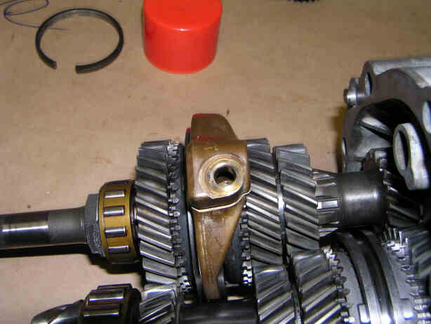
Posted by: DNHunt Nov 6 2005, 12:37 PM
Next I inserted it's shift rod.
Attached image(s)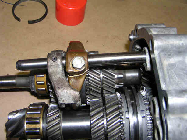
Posted by: DNHunt Nov 6 2005, 12:39 PM
Then I added the ball that is part of the detent in the tube.
Attached image(s)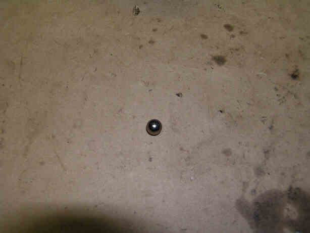
Posted by: DNHunt Nov 6 2005, 12:43 PM
All these balls, springs, and rods go in this hole in the intermediate plate. Beware the balls can come out of the holes that the shift rods pass through. All purpose grease is tacky enough to slow them down. I had to get down on my hands and knees to find one of the little suckers.
Attached image(s)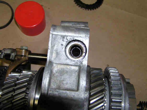
Posted by: DNHunt Nov 6 2005, 12:44 PM
Next comes a spring with the little rod inside it. Again grease.
Attached image(s)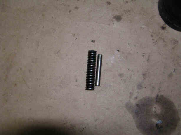
Posted by: Aaron Cox Nov 6 2005, 12:46 PM
as joe sharp said yesterday - the ball and stick game.
AA
Posted by: DNHunt Nov 6 2005, 12:48 PM
Then comes the second ball. You shoud be able to see it in the tube if you look through the hole for the 2nd, 3rd shift rod in the intermediate plate. Did I say I like grease?
Attached image(s)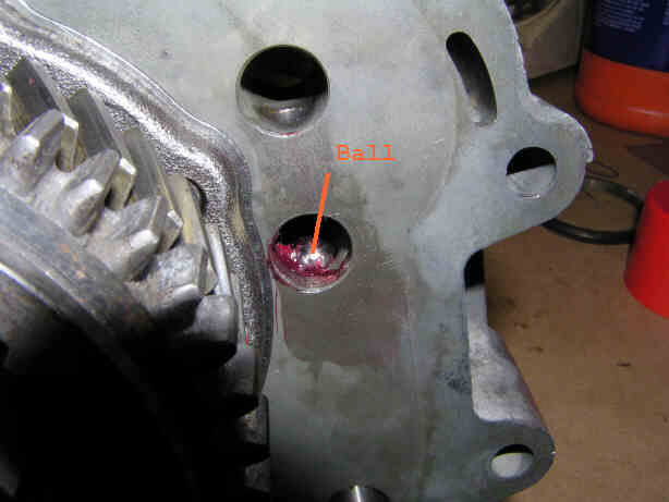
Posted by: DNHunt Nov 6 2005, 12:50 PM
Next I put the 2nd, 3rd shift fork on its' slider
Attached image(s)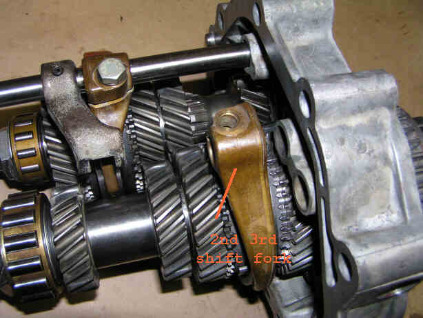
Posted by: DNHunt Nov 6 2005, 12:52 PM
Next, 2nd, 3rd shift rod! These bolts are only hand tight right now cause I'll adjust them later.
Attached image(s)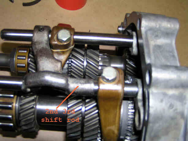
Posted by: DNHunt Nov 6 2005, 12:53 PM
Next is the little peanut thing in the tube in the intermediate plate.
Attached image(s)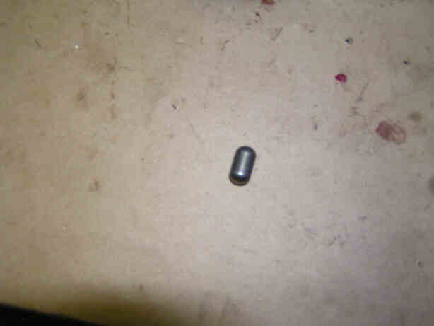
Posted by: DNHunt Nov 6 2005, 12:56 PM
After you shove it in you should be able to just barely see it through the 1st, reverse shift rod hole in the intermediate plate.
Attached image(s)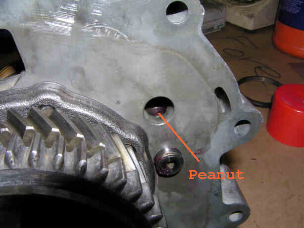
Posted by: DNHunt Nov 6 2005, 01:00 PM
Next the 1st, reverse shift rod and shift fork go on with the bolt finger tight.
Attached image(s)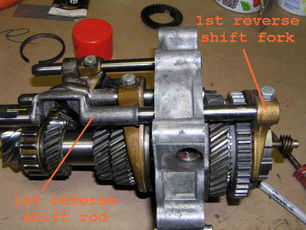
Posted by: DNHunt Nov 6 2005, 01:01 PM
The 3rd and final ball goes in the tube
Attached image(s)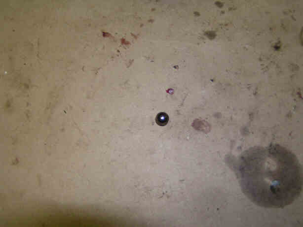
Posted by: DNHunt Nov 6 2005, 01:02 PM
Then the stiffer of the 2 springs
Attached image(s)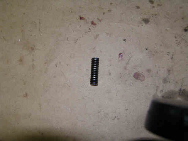
Posted by: DNHunt Nov 6 2005, 01:03 PM
You can see the last spring in the hole
Attached image(s)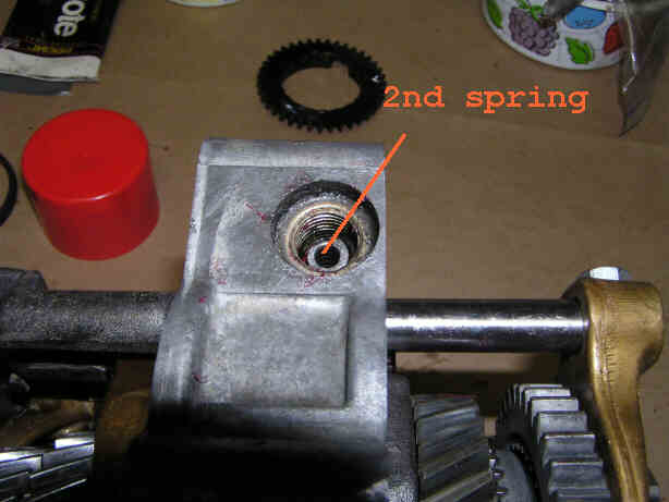
Posted by: DNHunt Nov 6 2005, 01:04 PM
The plug finishes it up
Attached image(s)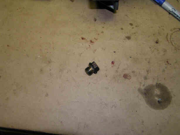
Posted by: DNHunt Nov 6 2005, 01:04 PM
Done with that
Attached image(s)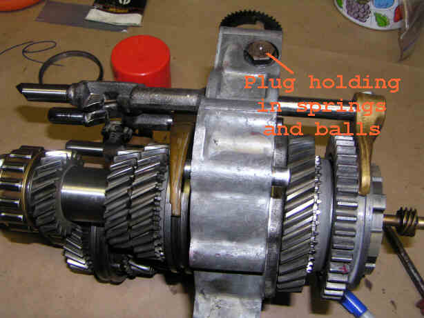
Posted by: qa1142 Nov 6 2005, 01:09 PM
Very cool stuff
Posted by: DNHunt Nov 6 2005, 01:18 PM
This is a side shifter!!!
Adjusting the shift forks for 2nd, 3rd and 4th, 5th can be done now. The balls and springs will hold the shift rods in neutral and the alignment jig supports the free ends of the rods. You should be able to see all of the notches in the shift rods lined up. Like this
Attached image(s)
Posted by: DNHunt Nov 6 2005, 01:19 PM
The jig holds everything nice and steady
Attached image(s)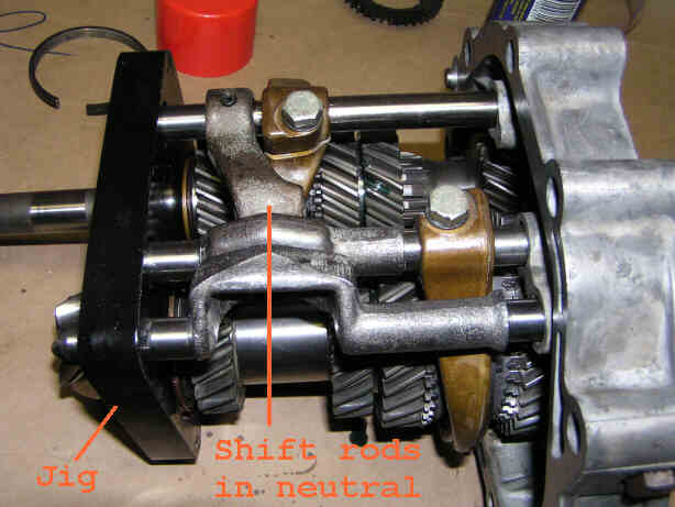
Posted by: DNHunt Nov 6 2005, 01:23 PM
Tighten the bolts when the sliders for 2nd, 3rd and 4th, 5th are centered between their respective gears. Here is what 4th, 5th should look like.
Attached image(s)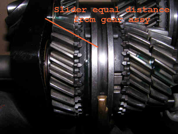
Posted by: DNHunt Nov 6 2005, 02:30 PM
Haynes manual calls for 1mm clearance between the back of the slider and reverse on its' shaft. Once I got that I tightened down the bolt on the shirt fork then rechecked it.
Attached image(s)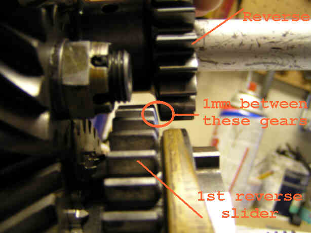
Posted by: DNHunt Nov 6 2005, 02:32 PM
The gear stack is now ready except for torquing the 30 mm bolt on 1st gear.
Attached image(s)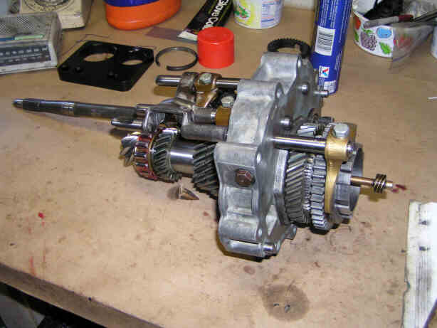
Posted by: DNHunt Nov 6 2005, 02:34 PM
The paper shims for the intermediate plate were not colored and the replacements in the gasket kit are not either so I had to measure them. I chose a none compressed area in each. There are passages or something where the castings are not solid and the sealing surfaces do not compress the shims. The old ones added up to .015".
Attached image(s)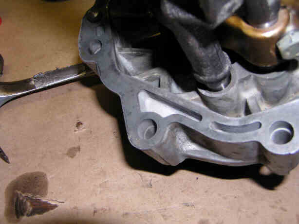
Posted by: DNHunt Nov 6 2005, 02:36 PM
One old shim measured .009"
Attached image(s)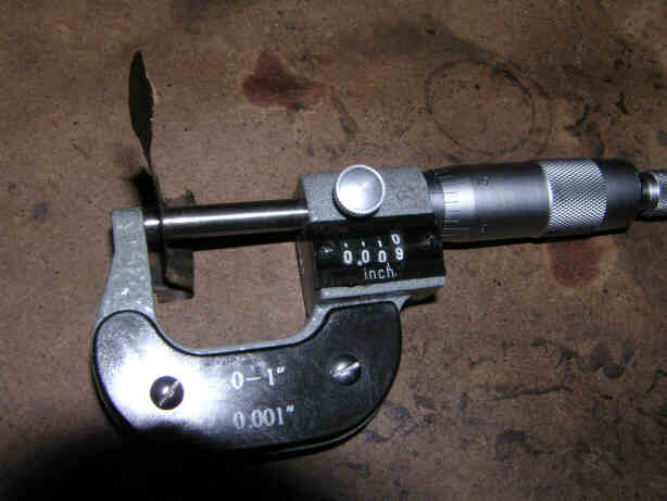
Posted by: DNHunt Nov 6 2005, 02:37 PM
The other old one was .006
Attached image(s)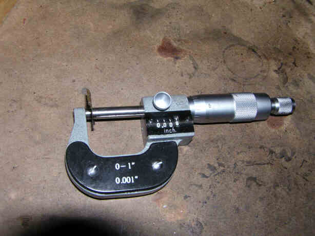
Posted by: DNHunt Nov 6 2005, 02:38 PM
It just so happens that there was an .009" in the gasket kit.

Attached image(s)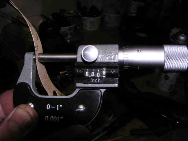
Posted by: DNHunt Nov 6 2005, 02:38 PM
And lucky me an .006. I guess I'm good to go.
Attached image(s)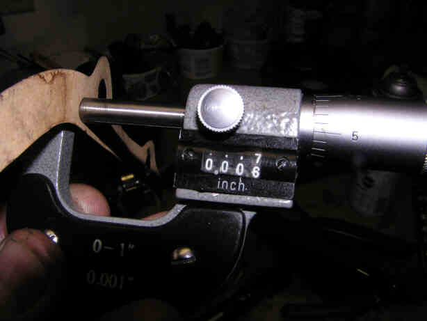
Posted by: DNHunt Nov 6 2005, 05:47 PM
I installed the 2 paper gaskets and installed the gear tack in the case. I used an old slider and my biggest pipe wrench to hold the pinion shaft so I could torque 1st gear. I know that looks gruesome but, it worked well.
Attached image(s)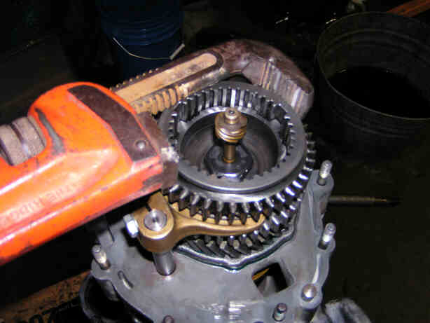
Posted by: DNHunt Nov 6 2005, 05:49 PM
Gear stack done and intermediate plate installed
Attached image(s)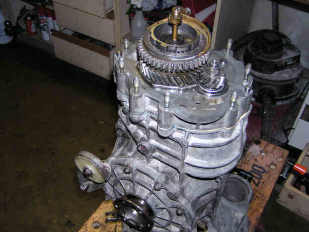
Posted by: DNHunt Nov 6 2005, 05:51 PM
Time for reverse. It starts with a roller bearing. The thrust washer remained on the shaft.
Attached image(s)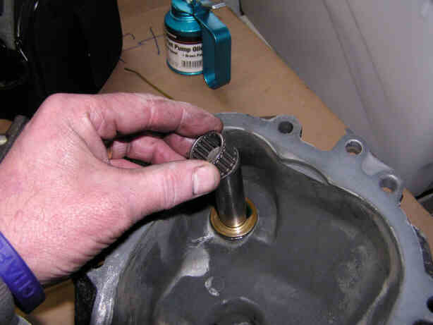
Posted by: DNHunt Nov 6 2005, 05:52 PM
Then a spacer
Attached image(s)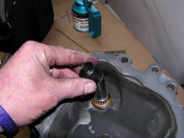
Posted by: DNHunt Nov 6 2005, 05:53 PM
Then a second roller bearing
Attached image(s)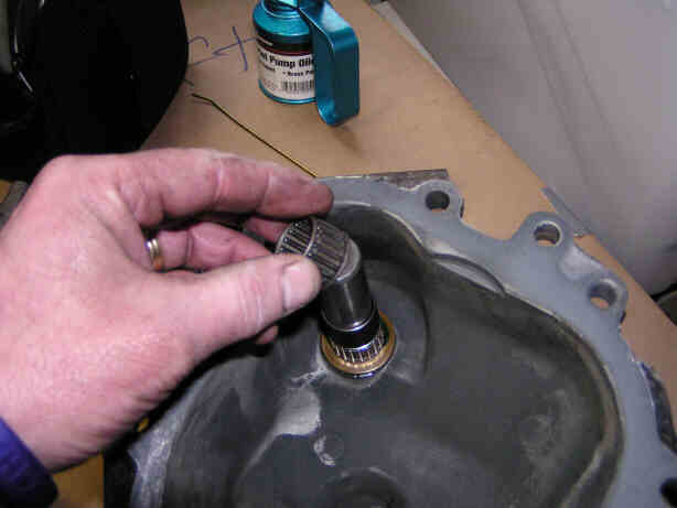
Posted by: DNHunt Nov 6 2005, 05:55 PM
Reverse gear slips over the roller bearings and spacer. The staight cut gears go toward the case
Attached image(s)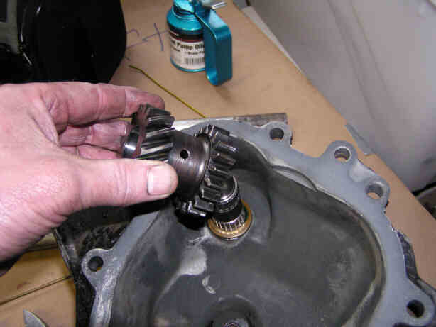
Posted by: DNHunt Nov 6 2005, 05:56 PM
Another bearing
Attached image(s)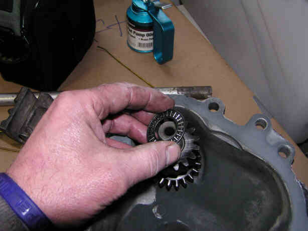
Posted by: DNHunt Nov 6 2005, 05:59 PM
Another thrust washer. This has a cut out machined into it that will overlap par of the race for the drive shaft in the intermediate plate. It's a bitch to keep on and oriented right. I used some grease to keep it in place.
Attached image(s)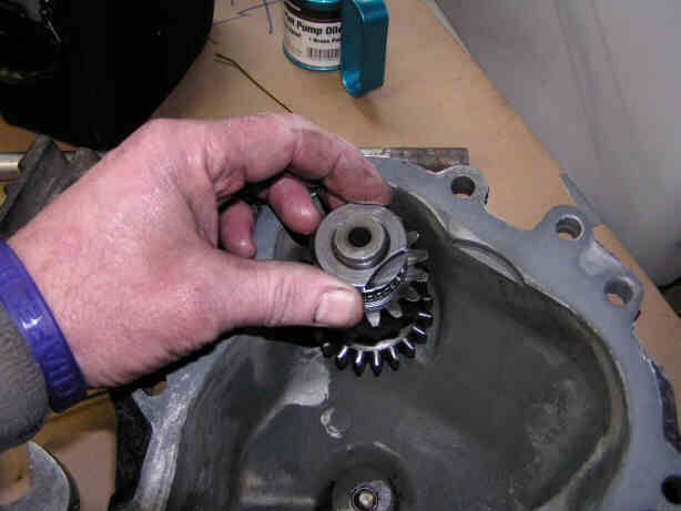
Posted by: DNHunt Nov 6 2005, 06:01 PM
I removed the bolt from the speedo drive and pulled the drive part way out. It makes it easier to seat the rear cover.
Attached image(s)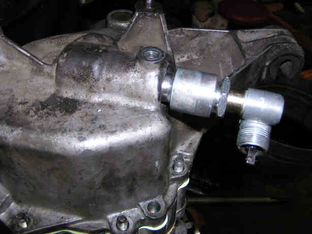
Posted by: DNHunt Nov 6 2005, 06:04 PM
Torqued down the cover nuts and replaced the speedo and speedo bolt . Everything seems to turn really well.
Posted by: DNHunt Nov 6 2005, 06:06 PM
Reconditioning the shift console starts with removing the roll pin holding the fork.
Attached image(s)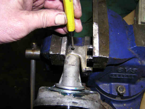
Posted by: DNHunt Nov 6 2005, 06:08 PM
Take it apart and this is what you have. Getting the small seal in the console out is a little tough without a seal puller.
Attached image(s)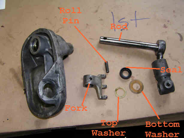
Posted by: DNHunt Nov 6 2005, 06:09 PM
Here is the seal for the rod
Attached image(s)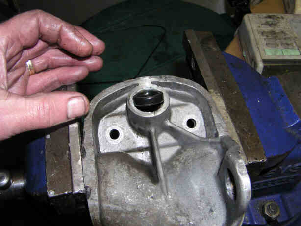
Posted by: DNHunt Nov 6 2005, 06:10 PM
The seal installed
Attached image(s)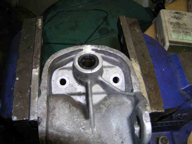
Posted by: DNHunt Nov 6 2005, 06:12 PM
The larger plastic washer goes on the shaft before reinserting it.
Attached image(s)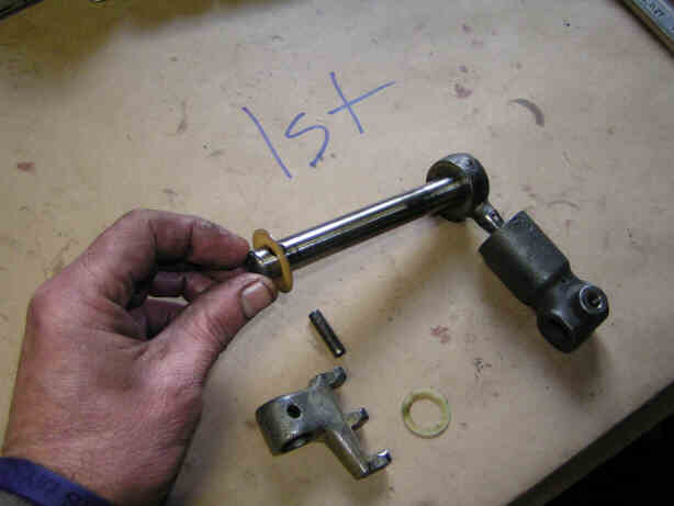
Posted by: DNHunt Nov 6 2005, 06:13 PM
Inserting the rod in the console
Attached image(s)
Posted by: DNHunt Nov 6 2005, 06:13 PM
The top washer is the smaller plastic one.
Attached image(s)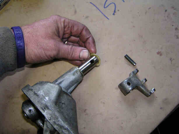
Posted by: DNHunt Nov 6 2005, 06:14 PM
The fork goes on the shaft. The long leg goes toward the bottom and the 3 lugs point the same direction as the lever on the rod
Posted by: DNHunt Nov 6 2005, 06:17 PM
Tap in the roll pin
Attached image(s)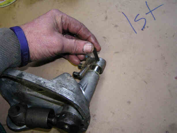
Posted by: DNHunt Nov 6 2005, 06:18 PM
Change the O-ring and istall the gasket and put it in. [Edit by McMark: No gasket. The gasket that looks like it goes here is for the tailshifter transmissions.]
Attached image(s)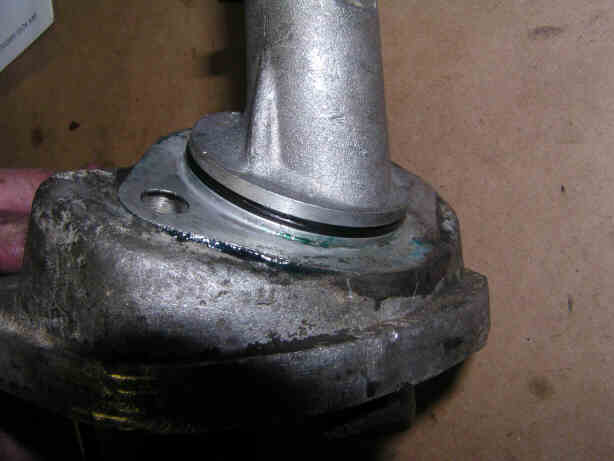
Posted by: DNHunt Nov 6 2005, 06:23 PM
A couple of casualities. A broken drive flange expansion bolt. I used the wrong torque spec. And a pinched O-ring
Attached image(s)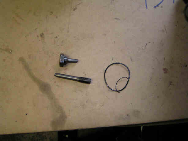
Posted by: DNHunt Nov 6 2005, 06:24 PM
Done!!  I just need to add Swepco. I sure hope it works
Dave
Attached image(s)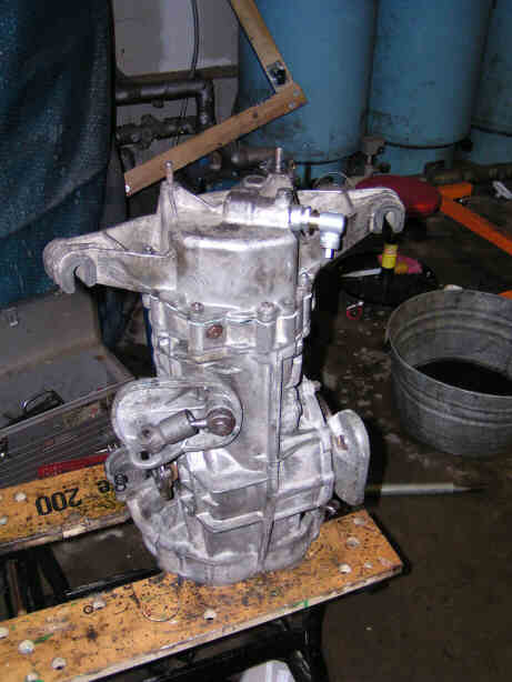
Posted by: LvSteveH Nov 7 2005, 04:31 AM
Thanks for putting so much time into documenting the rebuild. It's the best I've seen in terms of photos. Good Luck!
Posted by: ws91420 Nov 7 2005, 07:21 AM
Would it be possible to get this into an Adobe file? Would be a great resource while reassembly of mine.
Posted by: maf914 Nov 7 2005, 08:20 AM
Dave,
Once again, you've provided a super article. Great photos and narrative. Instant classic. Thanks so much.
Transmissions are still a mystery to me and will be until I take one apart. Kinda scary. 
Posted by: lapuwali Nov 7 2005, 09:54 AM
Excellent article, Dave.
The key thing to take away from this is that, unlike rebuilding an engine, a transmission is full of parts that all look the same, but aren't the same. It's very important to do something like what he did with the coat hangers so you dont' mix up the order of the parts on the shafts. Some people use a large table and simply place the parts on the table in the order they remove them from the shaft. The nice thing about the coat hanger is that it takes up less space, and there's less chance of some buddy, child, dog, whatever coming along and messing up the order of the parts on the table by accident.
Posted by: DNHunt Nov 7 2005, 10:28 AM
James
The other thing about the coat hanger is that it keeps the orientation of the parts the same. Some things like the cone washers and gears can't be flipped. Even with that I managed to mix up a couple of gears and I didn't catch it until I was trying to put the drive shaft in the intermediate plate.
Dave
Posted by: Bleyseng Nov 7 2005, 02:14 PM
I label the gears with black felt pen as I take them out, saves on time trying to figure out what is what. 
Posted by: McMark Nov 8 2005, 03:19 AM
Thank you Dave! Another great article for the Classics.
Posted by: ctc911ctc Aug 18 2020, 02:52 PM
I just read this entire thread - twice and watched the Dr. Evil video (a few times)
Question @http://www.914world.com/bbs2/index.php?showuser=598 , how did the tranny run after all of that work?
Thank you,
CTC911CTC
Posted by: 914werke Aug 18 2020, 04:52 PM
HOLY RESURRECTION! 
Powered by Invision Power Board (http://www.invisionboard.com)
© Invision Power Services (http://www.invisionpower.com)