Printable Version of Topic
Click here to view this topic in its original format
914World.com _ 914World Garage _ seatbelt buzzer wiring
Posted by: r_towle Nov 8 2005, 06:30 PM
ok....we are in the assembly mode on my sons restoration.
Does anyone have a pic of the wiring under the passenger seat...
Specifically I am looking for how it is mounted to the floor and the correct position.
the system is already jumpered, but I would like to mount it the way it is supposed to be, that way it wont rattle loose or get caught in something else.
Rich
Posted by: r_towle Nov 8 2005, 11:17 PM

Posted by: double-a Nov 8 2005, 11:52 PM
i could get a clue on this as well. i have two sets of wires coming from the seat area: one from the seat belt receiver, and one from the bottom seat cushion. which of these plugs to which wire?
~a
Posted by: mercdev Nov 9 2005, 12:07 AM
I'm not 100% sure since my car has had other PO modifications done...
The buzzer in my '76 is mounted perpendicular to the firewall, with the socket facing the dash. It's physical location is centered under the passenger seat with the wiring running directly back and under the firewall "cushion".
| CODE |
|----||-----firewall--------| | || \ / | | |x| \ / | | | | | ========dash===== |
Posted by: jim_hoyland Nov 9 2005, 08:24 AM
Ditto: I'm also looking to restore the original set up. A nice diagram with notes would be really helpfull
Posted by: 2-OH! Nov 9 2005, 02:23 PM
Sorry guys, all 3 of my previous restorations, I deleted all wiring and removed both units from under the seat...Used the Large Yellow wires to set up a hidden switch to keep the car from being stolen...
So I can't help other than to say I thought there was a picture in the Haynes Manual...I am pretty sure there is a picture in (can't remember the author...Bruce P****) the restoration book with the yellow and black 914's on the front... The picture is in Black & White but the wiring Diagram in the Haynes is correct because I used it to disconnect on my previous Restorations...
2-OH!
Posted by: dsmeyer Nov 9 2005, 05:01 PM
Just happen to have my '76 project car right here in the garage.
One of the few parts not yet removed.
It's very original, only about 32,000 miles.
Looks like they just connected the big yellow wire to bypass the buzzer.
Attached thumbnail(s)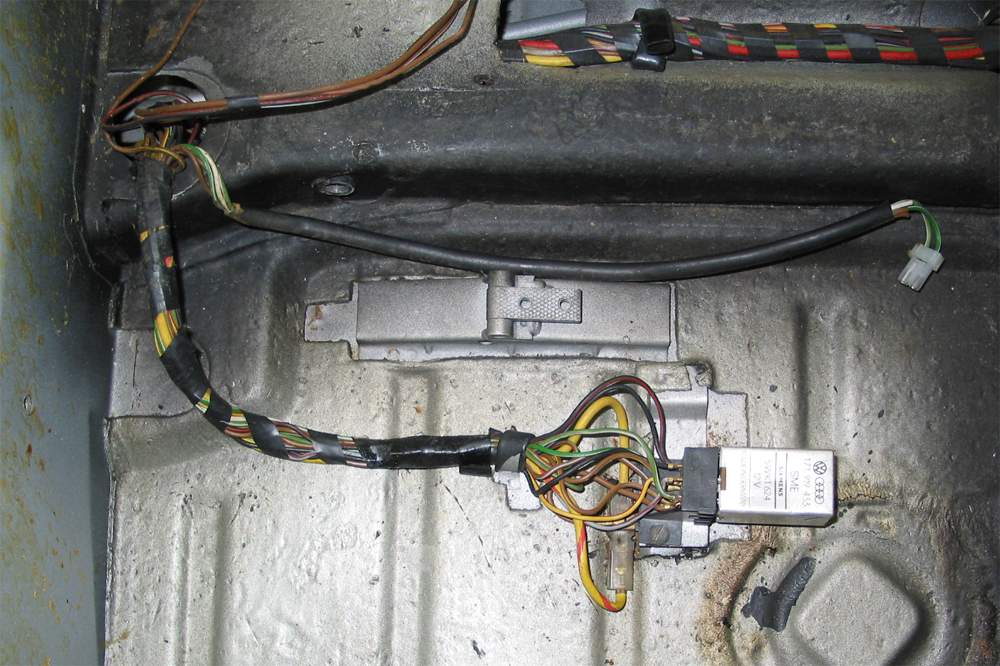
Posted by: dsmeyer Nov 9 2005, 05:02 PM
A little more detail...
Attached thumbnail(s)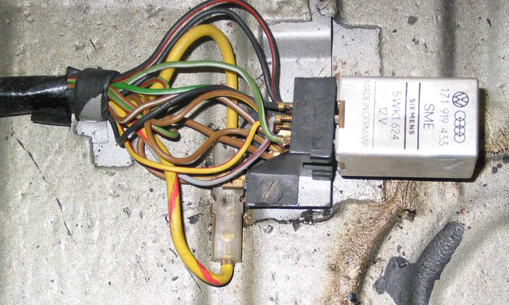
Posted by: Aaron Cox Nov 9 2005, 05:21 PM
wierd. i have a FAT relay under there.. like 2 or 3x as wide
Posted by: dsmeyer Nov 9 2005, 05:35 PM
| QUOTE (Aaron Cox @ Nov 9 2005, 07:21 PM) |
| wierd. i have a FAT relay under there.. like 2 or 3x as wide |
Haynes also shows a bigger box and calls it a Seat Belt Logic Switch.
The PO must have made some changes.
Posted by: 2-OH! Nov 9 2005, 05:36 PM
Yep, the fat relay lookin' do-dad is the seat belt interlock relay...If you weren't buckled up, the car would not start...
The one in the pic above is the buzzer for the seatbelt (and maybe door ajar) system...
75' & 76' had em' both under the passenger seat...
2-OH!
Posted by: lagunero Nov 9 2005, 06:13 PM
where all models fit with a relay that size? The PO on my '73 must have yanked it before I could 
Posted by: jim_hoyland Nov 9 2005, 09:33 PM
Nice picture; maybe we can get a good pic of the 2x /3x size. Would like to see someone label the connections. My relay is totally intact, but there are a lot of loose ends.
Posted by: double-a Nov 10 2005, 12:06 AM
here's how the relay/wires look in my '75. by all appearances, it has not been tampered with (car sat undriven for 20 yrs). still can't figure out which of the seat belt and seat cushion wires go to which plug receiver though.
Attached image(s)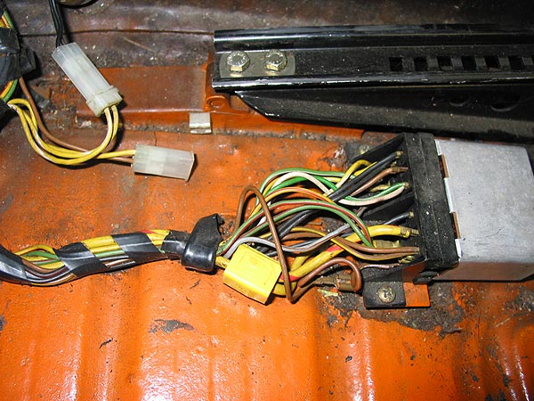
Posted by: double-a Nov 10 2005, 12:08 AM
here's another look, a bit closer.
~a
Attached image(s)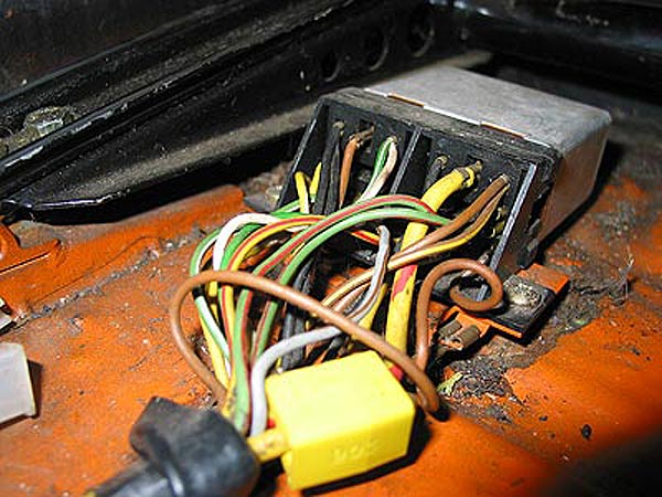
Posted by: jim_hoyland Nov 10 2005, 09:26 AM
Nice pic of the '75; I'm going to check mine tomorrow and compare.
Posted by: ejm Nov 10 2005, 06:53 PM
| QUOTE |
| by all appearances, it has not been tampered with |
the Scotch lock connector bridgeing the starter wires looks like tampering to me

Posted by: double-a Nov 10 2005, 08:37 PM
| QUOTE (ejm @ Nov 10 2005, 04:53 PM) | ||
the Scotch lock connector bridgeing the starter wires looks like tampering to me |
well i've only been at this for a couple years, i never would've guessed that that lock thingie wasn't original. it looks a lot better than some of the other bypass setups i've seen though. how can i undo it?
~a
Posted by: jim_hoyland Nov 10 2005, 09:22 PM
Mine was worse than I thought. First, the dash seat belt light works, so something is connected, I'm not sure what.
The only wires I can identify are: The green wire on the left side is part of the left seat belt switch and according to Hynes, the green wire with red stripe is the oil idiot light. I would like to re-do this mess so it looks original. Any tips would be appreciated.
Jim
Attached image(s)
Posted by: Jeff Bowlsby Nov 10 2005, 09:42 PM
Here you go guys, I hope this helps. This wiring diagram is for a 1974 model, I presume, but don't know if they are all the same...
Attached thumbnail(s)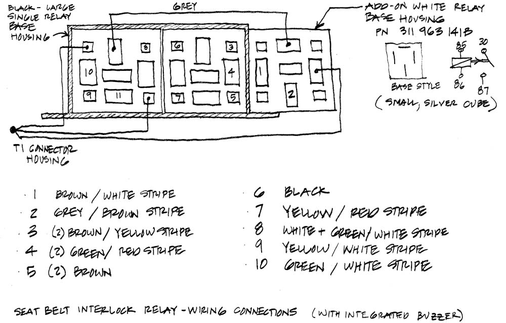
Posted by: Dave_Darling Nov 10 2005, 09:49 PM
| QUOTE (double-a @ Nov 10 2005, 06:37 PM) |
| it looks a lot better than some of the other bypass setups i've seen though. how can i undo it? |
Don't. You really don't want this thing to be fully operational--it is one more potential failure point for your starter circuit. It's yet one more place you can be losing voltage going to the starter, which is pretty much the last thing you want to happen. It's also stupid to require the seat belt to be fastened before you can start the car. Just... stupid.
If you want it to look original, then replace the main wiring harness so you will have all un-cut wires. If that's too extreme, solder the wires together and cover with shrink-tubing. Use more (large diameter!) tubing to encase all of the wires past the point where they are spliced, thus hiding the splices from view. But I'd have the yellow starter wire there just be a dummy, and have the yellow and yellow/red wires spliced together out of view.
Otherwise you (or the next owner of your car) will be back here in a few years, asking about "hot start relay kits" and other starter fixes...
--DD
Posted by: double-a Nov 10 2005, 10:05 PM
ok, i'll just leave it as-is, since the two wires have been joined with that scotch clip deal.
so why'd they even install these things in new models if they went bad so quickly? lemme guess... gov't requirements, right? 
~a
Posted by: jim_hoyland Nov 10 2005, 10:51 PM
Dave, Your point is well taken; you are right about the problems a fully functional relay causes. I'm sure that's the reason my looks like a disaster--but starts every time !
What Im looking for is how was it originally set up so I can more/less connect everything that isn't going to cause a major problem.
Jeff, thanks for the diagram. I think that will help.
Posted by: ejm Nov 11 2005, 01:18 AM
Scotch locks suck as a reliable way to make a connection. They cut the insulation and sometimes a few strands of wire guaranteeing a bad connection when moisture get in there.
This pic shows how the factory bridged the starter wiring when they eliminated the starter interupt relay in favor of the warning light/buzzer only.
Attached thumbnail(s)
Posted by: jim_hoyland Nov 11 2005, 08:44 AM
This may be a dumb question, but I really don't know: Where do the yellow wire go to. They are huge, I assume they are related to the start function. I don't recall seeing a yellow wire at the starter or solonoid. The pictures are great, hope to clean this mess up.
Attached image(s)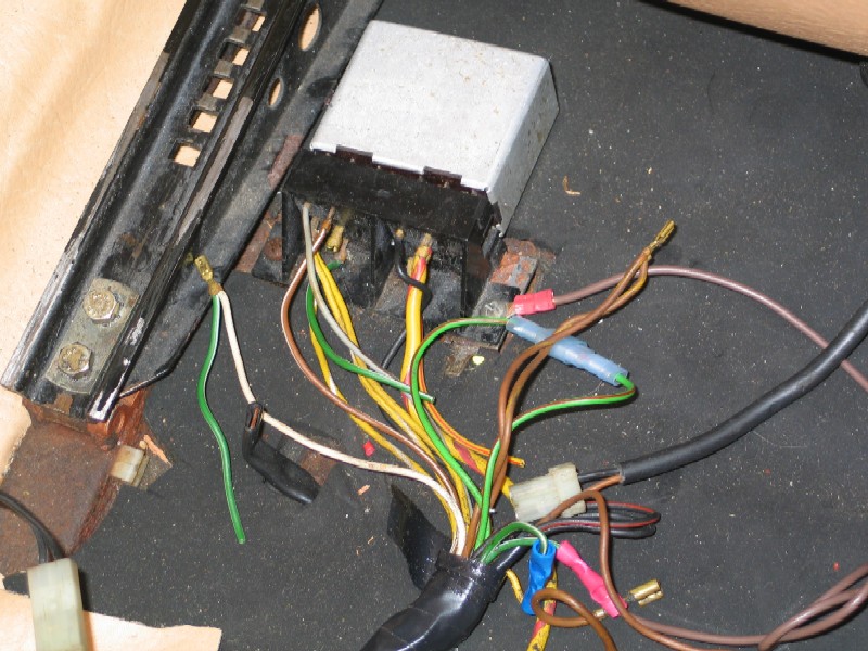
Posted by: Jeff Bowlsby Nov 11 2005, 08:48 AM
| QUOTE |
| Where do the yellow wire go to |
In my best Obi-wan voice...
Jim...the diagram....use the diagram....
Check you starter solenoid again, there should be a big yella wire going to it.

Posted by: r_towle Nov 23 2005, 08:29 PM
this diagram from Bowlsby should be in the classic thread...
Rich
Posted by: double-a Nov 23 2005, 08:43 PM
| QUOTE (ejm @ Nov 10 2005, 11:18 PM) |
| This pic shows how the factory bridged the starter wiring when they eliminated the starter interupt relay in favor of the warning light/buzzer only. |
looks like they just hooked them end to end with one of those rectangular plastic thingies that appear in other places on the car. maybe i'll go that route. or maybe i'll leave the scotch clip and hope for the best

~a
Posted by: jim_hoyland Nov 23 2005, 10:02 PM
I've been wondering how the relay worked. My only reference is how a standard power relay works: small current triggers a larger current. There are a lot of wires at passenger seat relay ie Bowslby's diagram. How do the seat belt wires, in-seat wires, and other work together ???
Really curious,
Posted by: r_towle Nov 23 2005, 10:38 PM
I was just informed that it may be that these have ground triggers verus positive triggers...
That explains all the ground wires...
It is clearly a multi function relay...for both seat pressure and seat belt connection..
Im bringing it to my EE Dad tommorow for a detailed anaylsis....cause I wanna know too....
Rich
Posted by: jim_hoyland Nov 23 2005, 11:06 PM
Now we're getting somewhere ! Really looking forward to getting the details
Posted by: MecGen Nov 24 2005, 06:56 AM
You Guys 
Keep us informed on what you find. Great info here.
Might be a good place for a car alarm.
Salut

Posted by: jim_hoyland Nov 24 2005, 08:22 AM
Exactly ! When we know how that thing works, there are prolly some new or unintended uses that it could help with.
Posted by: r_towle Nov 24 2005, 05:24 PM
ok..,.,.
I have delivered a complete wired up relay...wiring digrams etc...so...we should know by this weekend WHYit works and HOW is works...
Rich
Posted by: grasshopper Nov 27 2005, 12:34 PM
well???
Posted by: Carlitos Way Nov 27 2005, 04:50 PM
I'm not sure where I read this.. or if it is accurate... but wasn't there a recall to have dealers bypass this "feature" in the past?
Posted by: grasshopper Nov 27 2005, 04:55 PM
| QUOTE (Carlitos Way @ Nov 27 2005, 02:50 PM) |
| I'm not sure where I read this.. or if it is accurate... but wasn't there a recall to have dealers bypass this "feature" in the past? |
yes
Posted by: r_towle Dec 5 2005, 10:24 AM
This is from DAD,
Only partly (80%). I did spend several hours on it. Lots of diagrams but no analysis yet. I will get back to it but I can't promise when.
Within the module is a printed circuit board with several resistors, diodes, and transistors along with two relays. The other module is a relay (buzzer probably). I have reverse engineered most of the circuits but not enough yet to come to any conclusions. One problem is the relays are so badly corroded that I cannot trace the circuits tied to them. The rest of the circuits are clearly all the logic associated with the buzzer and warning light. I have traced most of them but ran out of time. If anyone has another module less corroded it would help. Also if there is any diagram of the leads coming to the module it would be very helpful in analyzing the insides of the module. All I have is the earlier 1973 version without a module.
One puzzle , not yet solved, is how many leads coming to the module are hot (12v). One possibility is the heavy leads you bypassed are the only source of 12v and only when the ignition is turned on.
Another possibility comes from the 1973 schematic which shows some black leads coming from fuse 11 which are hot all the time and could be trouble if shorted to ground. I am not sure when I can get back to it so if I were you I would just terminate them with some protection to prevent grounding.
One question I have is "Do you know of any time when the buzzer and/or light is supposed to come on without the ignition being on....such as key left in lock (off) and door opened?
Posted by: r_towle Dec 5 2005, 02:57 PM
Im gonna need some help here.
Does anyone have a seatbelt relay that they dont want and yet is not all rusty...
And/or...does anyone have a detailed wiring diagram for the 74 seat belt buzzer system...possibly out of the true porsche service manual???
Rich
Posted by: jim_hoyland Dec 5 2005, 06:28 PM
Glad to see this is still a work in progress. Very interested in learning more here; anuy one got a donar ?
Posted by: Dave_Darling Dec 5 2005, 06:35 PM
The wiring diagram is available here:
http://www.pelicanparts.com/914/914_electrical_diagrams.htm
The Dreaded Seatbelt Interlock Relay is on Page 4 of the 74 diagram, and is component J34.
The only power-in on the relay is on the following terminals:
15 (black wire) constant power.
L (yellow/red wire) switched power--after it goes through the warning light.
C (yellow wire) power when the key is in "start" only.
H (grey/yellow wire) switched power, which runs the "door ajar" buzzer.
...Come to think of it, I believe that "L" isn't actually an input, but an output for the light. When the relay grounds L, the light comes on.
I have a relay somewhere in my Stash Of Parts ™, but it'll take a long time for me to find it...
Basically, the relay does nothing at all but turn on the light and interrupt the signal going to the starter. The only wires going to it that are in any way important are the ones where two wires are crimped into one metal connector. If you want to take the socket out completely, then splice together any pair of wires that are crimped into the same metal connector. That will leave all the functionality of the car intact, except for the door-ajar buzzer, the seatbelt warning light, and the starter interrupt.
--DD
Posted by: Mikey914 Feb 8 2006, 12:34 AM
Ok, I'm missing the relay, so rather than waste my money buying another, I can connect The heavy yellows together, and then connect all double clipped wires together. Then secure remaining wiresou to of the way, correct? 
Posted by: Rleog Feb 28 2013, 07:58 AM

This may be a dumb question, but I really don't know: Where do the yellow wire go to. They are huge, I assume they are related to the start function. I don't recall seeing a yellow wire at the starter or solonoid. The pictures are great, hope to clean this mess up.
I found this thread very useful while reconditioning my wiring harness, which is out of the car. As Dave suggested, you can use the wiring diagram to answer Jim's question.
More easily for future users:
The Yellow/Red stripe wire originates on the Regulator Plate (Relay Board) within the 14 pin connector at terminal #1 then runs to the seat belt "Logik-Relais" (Bosch's nomenclature) The solid Yellow wire runs from the seat belt Logik-Relais to the steering column switch.
Thanks to all who contributed to this thread.
Posted by: Dave_Darling Feb 28 2013, 01:07 PM
That's true for the 74 cars, and some 75s. The "Logik-Relais" is the Dreaded Seatbelt Interlock Relay, which was added in 74 as a DOT-mandated safety measure and then removed in 75 as a DOT-mandated safety measure. In earlier and later cars, the yellow wire runs from the ignition switch to the relay board without being interrupted by the relay.
The relay is a failure point; it is common to remove it and splice the two thick yellow wires together to bypass its function.
--DD
Posted by: r_towle Feb 12 2023, 03:45 PM
Bump to top
Posted by: jim_hoyland Feb 12 2023, 06:50 PM
So, it relay works by ground to make current flow And the main grounds seem to be the seat belt and seat sensors. Anything else ?
Posted by: r_towle Feb 12 2023, 07:04 PM
So, it relay works by ground to make current flow And the main grounds seem to be the seat belt and seat sensors. Anything else ?
Seriously dusty cells on this one….but
The work around is to ground all brown wires to the chassis.
Direct connect the large yellow wires that is ignition key to starter solenoid.
That solves the issues.
Powered by Invision Power Board (http://www.invisionboard.com)
© Invision Power Services (http://www.invisionpower.com)