Printable Version of Topic
Click here to view this topic in its original format
914World.com _ 914World Garage _ push rods - cut to length
Posted by: qa1142 Dec 10 2005, 04:05 PM
Ok so I searched and found a thead on rocker geometry (nice pdf too  )
)
So who can tell me (step by step) on how to cut Jake's rods to lenght 
Sorry had to put it that way 
Posted by: DNHunt Dec 11 2005, 08:17 AM
I'm not sure I can give you the blow by blow but, here is what I did.
You need a dial indicator and some way to hold it on the head so you can read valve openning. You need and adjustable pushrod and probably light weight valve springs. You need a day uninterrupted.
There are 2 goals. As much valve lift as possible and the adjusting screw parallel to the valve stem at half lift. Of the 2 the second is more important. You use changes in pushrod length and addition and subtraction of shims under the rockers to achieve this.
I sort of bodged up a jig to hold the dial indicator and then I welded up a rectangle of angle iron to clamp it down. The tip of the dial indicator sits on the valve spring retainer. The lightweight springs I found at the harware store, nothing fancy.
Attached image(s)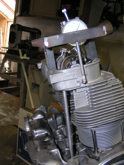
Posted by: DNHunt Dec 11 2005, 08:26 AM
Find total lift first and then rotate the engine until you get half lift. Eyeball to see if the adjuster and the valve stem line up. One other thing you have to make sure you leave some threads available on the adjuster screw for valve adjustments.
Attached image(s)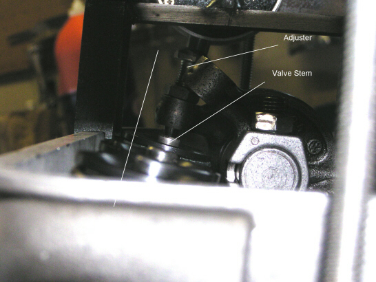
Posted by: DNHunt Dec 11 2005, 08:33 AM
Add and subtract shims and adjust the pushrod until you get it. Damn boring, just trial and error.
After the first cylinder it gets a little easier cause you know about where to start. Lifts will be close but not exactly the same and shims may be different. On my engine 1 side has .060 shims and the other side is .045.
If you get a degree wheel you can also clock the cam. It is alittle different that the card will say. I just downloaded and printed a wheel.
Attached image(s)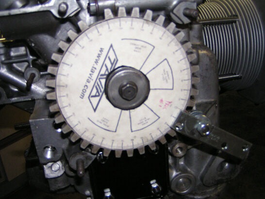
Posted by: DNHunt Dec 11 2005, 08:38 AM
I cut the pushrods with a cutoff wheel on my chop saw. I used a straight edge and square to check for equal lengths and then deburred the ends. If you get a couple of old lifters you can use these to drive the ends on the pushrods.
Dave
Posted by: URY914 Dec 11 2005, 08:43 AM
As Dr. Hunt said, it is a SLOW process. You have to set up the dial indicator (d/a) on the engine or on a bracket or jig as in the pic above. I did mine while the engine sat on the floor and the d/a was positioned on some scrap iron clamped to the head. The d/a must be very secure and not move AT ALL. You'll need an adjustable pushrod.
I did mine a few months ago while taking to Jake on the phone at 11:00 pm. (How many other suppliers/vendors would do this?) As you rotate the engine by turning the crank by hand you are trying to watch the d/a to get a measurement on the amount of lift. Jake should beable to give you a ball park lift measurement to start with. Than you will lenghten or shorten the adjustable p/r to increase of decrease the lift.
It took me several nights of this before I really got the hang of the process and was able to work it out. You will be taking the shaft and rockers off and on 30 times before you get it done. As Jake said, it is hard to discribe. Once you start in on it you'll come to realize how the process works.
I wish these was a step by step method written somewhere but there doesn't seem to be a good one out there.
Paul
Posted by: Racer Chris Dec 11 2005, 08:44 AM
Once I have the correct length calculated I cut them off with a bandsaw about .02-.03" longer than the finished length. Then I finish cutting them in a lathe to the precise length plus or minus a few thousandths. To complete them place the end with the tip into an old lifter, standing on a workbench. Insert the second tip and drive it on with a dead blow hammer against a second lifter.
Posted by: DNHunt Dec 11 2005, 08:53 AM
Paul
You are right. You keep adjusting and trying. Total pain in the ass. Plus wavy washers just try and jump off of the rocker studs and down the pushrod tubes.  There must be something equivalent on a six but if there isn't that would be one good reason to do a conversion just to avoid valve train geometry.
I don't know how Jake could do it over and over. Maybe that's why he gets crotchety. 
Dave
Posted by: URY914 Dec 11 2005, 09:02 AM
When I cut mine I set up a jig so they would all measure the same length. I clamped two steel blocks to the table top and I used a stationary belt sander to carefully take mat'l off to get them the same length. I worked them until they just fit between the blocks. Than a hand file to get off that last .00001.
This is almost as much fun as measuring the lift. 
Paul
Posted by: URY914 Dec 11 2005, 11:19 AM
Ain't they pretty. 
Attached thumbnail(s)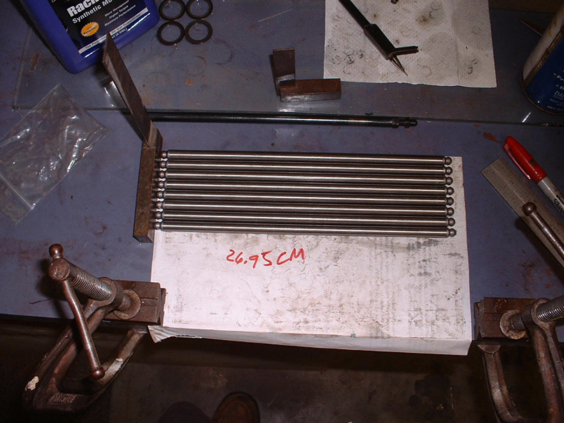
Posted by: URY914 Dec 11 2005, 11:25 AM
dial indicator clamped to the engine bar....
Attached thumbnail(s)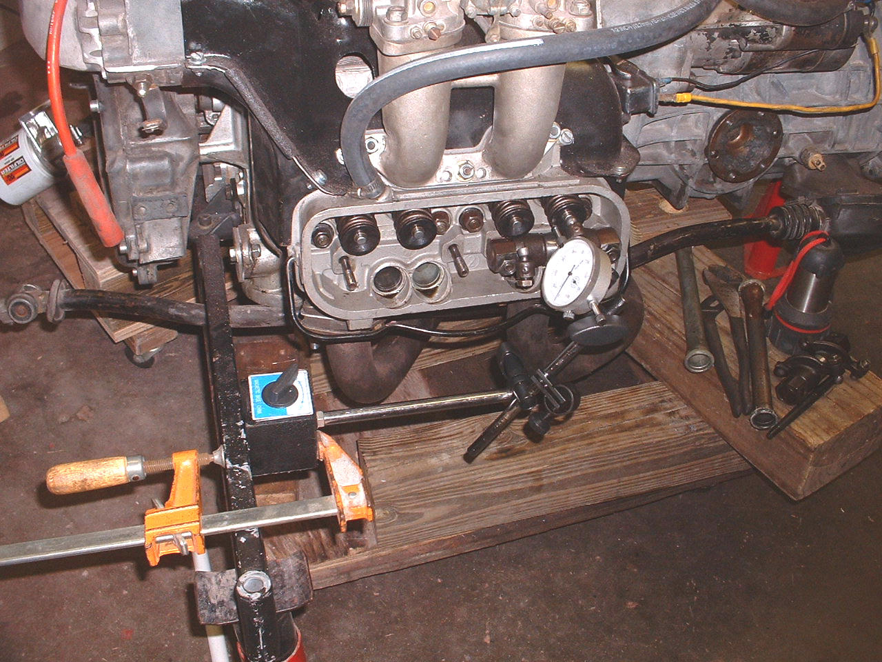
Powered by Invision Power Board (http://www.invisionboard.com)
© Invision Power Services (http://www.invisionpower.com)