Printable Version of Topic
Click here to view this topic in its original format
914World.com _ 914World Garage _ How flexible do you think a stock, trailing arm is
Posted by: Racer Chris Dec 16 2005, 06:19 PM
Specifically I am looking for rotational stiffness (ie. twist) of the trailing arm due to the tire contact patch resisting sideways sliding of the car. I'm only interested in forces greater than 1G during cornering.
I already know what happens but go ahead and take a guess. 
I'll post pictures of my test fixture shortly.
Posted by: TimT Dec 16 2005, 06:25 PM
Chris the trailing arm appears to be a pretty stout piece. Im interested in your info, and I could maybe model a trailing arm on a FEA program that I have..
lemme find the FEA output I did for my 911 roll cage
Posted by: J P Stein Dec 16 2005, 06:26 PM
WAG:
1 deg @500 lbs.
I'm assuming you're trying to twist it.
Posted by: airsix Dec 16 2005, 07:09 PM
What exactly do you mean by "1G". I'm sure you don't mean a force equal to the weight of the trailing arm.  Do you mean something like a force equal to 1/2 the weight of the car with a moment arm equal to the radius of the tire/wheel combo? Are you measuring deflection of a rigidly monted trailing arm, or are we including bushing flex too?
By the way, this is a cool thread. Can't wait to hear about your experiment. Good stuff.
-Ben M.
Posted by: ppickerell Dec 16 2005, 07:41 PM
Chris,
Do you intend to test before and after boxing?
Posted by: Dave_Darling Dec 16 2005, 07:54 PM
I'm guessing that most of the flex happens in the tube where the pivot shaft sits, not in the box section of the arm.
--DD
Posted by: spare time toys Dec 16 2005, 08:08 PM
My guess is it has flex designed into it at an amount equal to slightly less than the tensel strength of the material from which it was made. IE it will bend before it will snap like an airplane wing 
Posted by: Racer Chris Dec 16 2005, 08:24 PM
So far JP is the only one really on the right track. 
You're only off by a factor of two.
What I did was mount the trailing arm pivot shaft in a support fixture I fabricated. Then I welded the base plate of the fixture to my 800lb welding bench.
Attached image(s)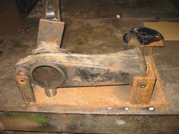
Posted by: Racer Chris Dec 16 2005, 08:26 PM
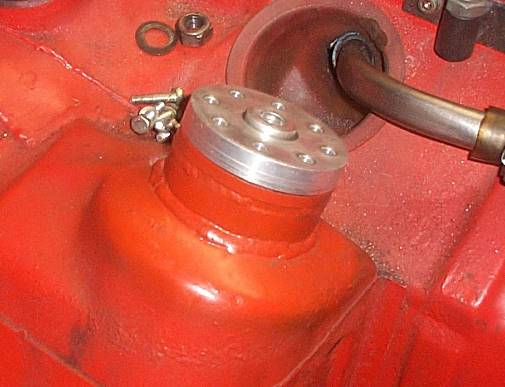
Then I attached a 5ft piece of structural tubing to the side of the trailing arm where the bearing retainer bolts on.
Attached image(s)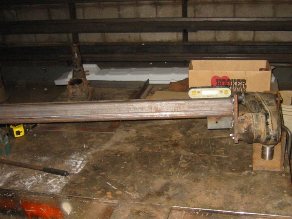
Posted by: Racer Chris Dec 16 2005, 08:32 PM
by putting a 200lb man's weight at the end of the structural tube I can simulate a 1000lb twisting force on the trailing arm.
By my rough calculations this is somewhere in the ball park of what happens when a slick shod race car goes around a corner at 1G+. Keeping in mind that the contact patch is roughly 1ft away from the axis of the wheel and the slicks allow a car to corner at close to 1.5G.
The digital level is on the structural tube to measure the rotational deflection of the trailing arm in 0.1 degree increments.
Posted by: Racer Chris Dec 16 2005, 08:34 PM
I had a friend sit on the end of the tube and saw the level move by one full degree! 
Attached image(s)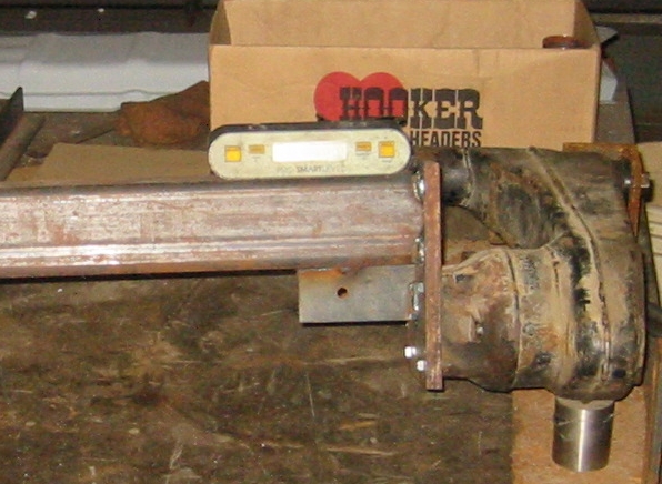
Posted by: Racer Chris Dec 16 2005, 08:40 PM
I have several more tests planned already.
1) measure a trailing arm with the standard box kit installed.
2) measure a trailing arm with my idea of a better stiffener. *
3) measure the fore/aft deflection of the arm by applying the load 90 degrees to what I did for this test. This will simulate what happens under 1G of braking force.
* My better stiffener will be very simple, lightweight, and will allow me to make a camber change to the trailing arm at the same time.
I just need to make another fixture so I can weld it together with the correct geometry. 
Posted by: TimT Dec 16 2005, 08:41 PM
Put the level on the trailing arm, not the lever
let all pieces be at rest, zero the level, given the odd profile of the trailing arm.. maybe some foam or balsa wood will be needed to make a suitable platform for the level
the reason I say this is there is deflection/movement in the plate that you bolted to the bearing keeper
In all testing and modeling are good... 1 deg at 1G wonder what they were designed for ?
Posted by: TimT Dec 16 2005, 08:42 PM
and yes I see the angle you have welded on the botton of the setup
Posted by: SpecialK Dec 16 2005, 08:43 PM
....go on.... 
So can you tell with your set-up which area was/is most susceptible to torsional loads? e.i.- where would "beefing it" by most effective?
p.s. - someone mentioned FEA software earlier in this post. I'm still in the process of honing my CAD skills, and found a company that has a "free", limited (can't import CAD files, but has a descent CAD program attached), 300 node version of their software for engineers. I downloaded it a couple of weeks ago, but haven't had time to mess with it too much yet.
http://www.nenastran.com/newnoran/freeDemo.php
The 300-node version is about 2/3's of the way down the page.
Posted by: andys Dec 16 2005, 08:57 PM
Chris,
This is exactly the kind of testing required to provide a benchmark by which to compare against. My custom trailing arms took so much effort fabricate that by the time I was finished, I was frankly too burned out to continue on with making a test fixture. I'm glad you're doing it!!
Unless you intend on making the stock trailing arm your "standard", you'll otherwise need to qualify your fixture. If you don't, then your data will be flawed (unfortunately). You'll need to first determine how much the test fixture deflects under load. Don't get me wrong, cause it's always seemingly easy to blow holes in someone elses work, but that's not my intention. Continue on, and do share your results; I remain very interested in your work. Are you going to test to fail?
I think if you examine the stock trailing arm design, I think you'll find it quite good (from a design standpoint). The design of course, was dictated by production requirements, but it is still very good. The area I never liked, was the pivot shaft and how it ties into the chassis mounts. Think about the camber and toe adjustment. You must deflect the inner ear in order to move it around. I've seen where some try to re-inforce the inner ear, only to have it crack. In my opinion, the inner ear is just crying for a spherical joint or conformal structure of some kind......sorry, guess I'm getting a little OT.
Andys
Posted by: goose2 Dec 16 2005, 09:06 PM
If you mount the level in various locations on the trailing arm...gobs of modeling clay would work....then load the lever arm....you'll be able to factor out any mounting plate flex while determining where the actual flex is occurring.
Posted by: TimT Dec 16 2005, 09:12 PM
| QUOTE |
| If you mount the level in various locations on the trailing arm...gobs of modeling clay would work....then load the lever arm....you'll be able to factor out any mounting plate flex while determining where the actual flex is occurring. |
Yes..
but I wonder how much the chassis yields?
chasing the dragon..
very cool
Posted by: rick 918-S Dec 16 2005, 09:21 PM
Put that level at the in board mounting in the direction of the pivot bolt and see what happens.
Posted by: URY914 Dec 16 2005, 09:21 PM
Chris,
This is what the pro teams call "off season testing".
P
Posted by: Racer Chris Dec 16 2005, 09:23 PM
Put the level on the trailing arm, not the lever
I am confident that wouldn't change the test results Tim.
I have a good sense of structural integrity (for lack of a better term).
What happened was exactly what I predicted. Pretty much ALL of the movement occurred in the box section of the trailing arm. It was very easy to observe this during the test. The movement was not linear along the length of the box section either. Slightly less deflection was observed toward the front where it is wider.
The fixture did not deflect.
The structural tube/plate connection to the trailing arm did not deflect.
The pivot shaft housing did not deflect.
The tube and forging section of the trailing arm did not deflect.
Very minor movement of the outer pickup bracket was observed. This bracket was a reinforced stock unit. I also have stock and my custom brackets I can test.
The loads I imposed were well below the elastic limit of the materials of the trailing arm. It returned to the exact starting position after multiple repeated tests. I had no plans to test to the failure point but that is not a bad idea. Next would be to have two men lean on the bar.

Posted by: r_towle Dec 16 2005, 09:34 PM
and you told me you were busy... 
Posted by: Racer Chris Dec 16 2005, 09:36 PM
Unless you intend on making the stock trailing arm your "standard", you'll otherwise need to qualify your fixture.
The area I never liked, was the pivot shaft and how it ties into the chassis mounts. Think about the camber and toe adjustment. You must deflect the inner ear in order to move it around. I've seen where some try to re-inforce the inner ear, only to have it crack.
My research is primarily aimed at Production race cars that receive custom modifications by me. With that in mind I intend to make a fixture which will allow me to measure stock trailing arms for damage, and will allow me to make minor alterations to the relationship between the pivot axis and the axle axis, ie. static camber angle.
When I raise the pickup points I use a 3/16" plate for the inner ear that is much more resistant to cracking than the stock sheet metal, yet allows for changes to the pivot shaft angle. The plate can be bent minutely if desired by striking it with a BFH. The range of adjustment necessary is very narrow so the stock system continues to be suitable for my application. My goal is always sophistication in planning and simplicity in operation and appearance.

Posted by: Racer Chris Dec 16 2005, 09:38 PM
| QUOTE (r_towle @ Dec 16 2005, 10:34 PM) |
| and you told me you were busy... |
I had exhaust system parts cutting in the bandsaw the entire time I was working on this.

Posted by: rick 918-S Dec 16 2005, 09:38 PM
There is no way that box would flex before that mild steel piece of 3/8" flat plate would deflect. Put rhe level on the arm.
Posted by: TimT Dec 16 2005, 09:41 PM
| QUOTE |
| I am confident that wouldn't change the test results Tim. |
I never said it would change the results...
Im just giving some insight based on what I do.. sometimes I get to go and strain gauge a bridge..
I see a couple between where you have the level, and the c/l of the trailing arm assembly, I also see a source of error there, but this is moot
Your testing process and methods are sound.
You mentioned the trailing arm rotated one degree.
We can learn where to reinforce the trailing arm, instead of welding all that heavy factory reinforcement on
good stuff
Im going to measure a spare trailing arm I have and model it.. It will be neat to see how it compares with your testing
Posted by: Racer Chris Dec 16 2005, 09:44 PM
One more goal I have is to possibly be able to tweak traling arms that have been slightly bent from hitting a curb for instance. At some point they become deflected beyond repair but I think some will be restorable.
Erik had one change between 1 - 2 degrees of camber with no toe change after he slid across a curb at Mid-Ohio when he spun going through turn one in qualifying. Turn one is taken at about 90 mph.
Posted by: J P Stein Dec 16 2005, 09:50 PM
| QUOTE (Racer Chris @ Dec 16 2005, 06:24 PM) |
| You're only off by a factor of two. |
Hay, it was a WAG, not a SWAG.......
I would have had to charge you for a SWAG
Posted by: Racer Chris Dec 16 2005, 09:56 PM
It's half inch plate Rick. The box section of the trailing arm is only sheet metal.
Believe me, I am very careful with testing like this. What appears to be crude is very well thought out and my observations are made thoroughly.
I see a couple between where you have the level, and the c/l of the trailing arm assembly, I also see a source of error there, but this is moot
You are correct but the stiffness of my components was chosen to be well beyond what I needed for these tests. The structural tube is 3x3x1/4"w. The gusset was included to spread the applied force to all four bolts at the mating surface. The trailing arm is resting on a single point along the weld bead beneath the round tube section and it can shift freely at that point if it wants to when the load is applied.
Posted by: TimT Dec 16 2005, 10:03 PM
Chris, all my observations are made based on what I do for a living.. "test things"
you have it all covered..
having said thay you could take your invesitgation to another level, and find where the trailing arm needs to be reinforced..
if you think the trailing arm need to resist torsion more, there is a real easy way to do that, and that is without welding on that trailing arm reinforcement stuff
Posted by: J P Stein Dec 16 2005, 10:06 PM
OK, agree with your load guesstimate.....if about 90% of the weight is on the outside rear tire, so....
Do a bit of rerigging so you can do the test with bushings in the trailing arms. I suspect that most of the plastic bushings
will cause a goodly amount of deflection.
If you push out 1 deg of neagtive at 1G as it sits, bushings would take another 1/2 deg, me thinks.
Posted by: Brett W Dec 16 2005, 10:11 PM
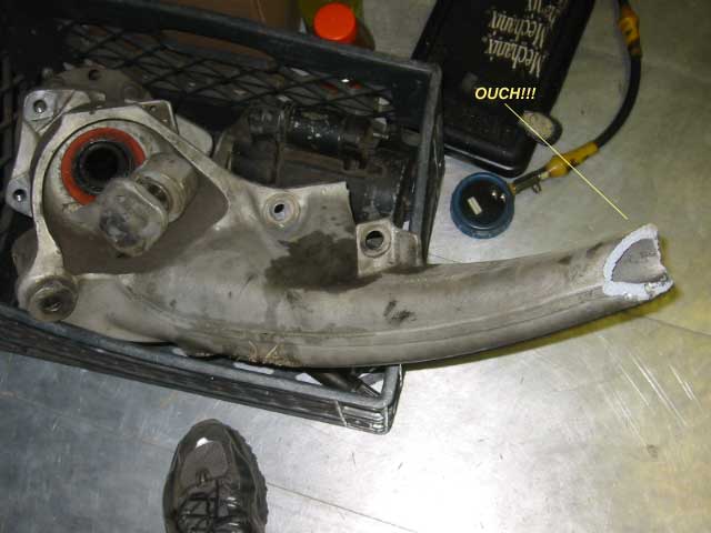
Good job Chris. I have meant to do this but I had no interest in keeping the stock trailing arms though. Here is what happens when you exceed the point of elasticity.
Attached image(s)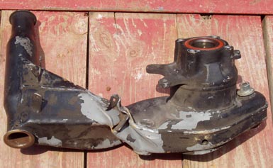
Posted by: Brett W Dec 16 2005, 10:13 PM
dfgdsgs
Attached image(s)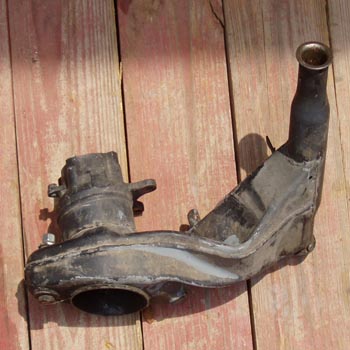
Posted by: URY914 Dec 16 2005, 10:21 PM
I spoke to a GT2 racer a Sebring once (actually more than once) and he said he cut a 1 3/4" hole thru the trailing arm and welded in a piece of tubing. The tubing stuck out of the arm about 3/16" on both sides, just enough to get a good weld around it. Said he could tell the differance next time out.
Sounds easy to me. 
Posted by: TimT Dec 16 2005, 10:27 PM
heheh
Paul thats correct
use tertiary reinforcement, make that big trailing arm box section into smaller individual sections...
my thoughts were other than a tube.. but its the same in the end
Posted by: Racer Chris Dec 16 2005, 10:31 PM
if you think the trailing arm need to resist torsion more, there is a real easy way to do that, and that is without welding on that trailing arm reinforcement stuff
Tim,
If I had a strain gauge laying around the shop it would have been on the trailing arm. Then moved to several locations for a real thorough analysis. I have a very good idea of what will work to cut down on the torquing of the trailing arm. I think about 4 ounces of sheet metal is all I need to cut the flex by more than 50%.
One problem with the factory style stiffening is it reinforces in the wrong way, by doubling up on material thickness. I don't want to prevent the arm from bending when it is hit by another car that drives into the side of me. I only want it to limit the flex from cornering loads.
When you see what I do you (not you Tim) will be surprised at the simplicity.
Do a bit of rerigging so you can do the test with bushings in the trailing arms. I suspect that most of the plastic bushings
will cause a goodly amount of deflection
This test was done with my Delrin bushings installed. The only thing holding the trailing arm to the fixture was the ends of the pivot shaft. There was no observable movement at the tube that supports the bushings.
I have meant to do this but I had no interest in keeping the stock trailing arms though.
I have no interest in abandoning the stock trailing arms.
That thing is quite a pretzel. How'd you do that?
Posted by: URY914 Dec 16 2005, 10:32 PM
Wrapping it with sheet metal does help to a degree, but you really need to get inside and tie the sides of the box together, so to speak. 
Paul
Posted by: Racer Chris Dec 16 2005, 10:34 PM
| QUOTE (TimT @ Dec 16 2005, 11:27 PM) |
| my thoughts were other than a tube |
Yep...
I'm planning to kill two birds with one stone. Can't do that by just inserting a tube.
Posted by: TimT Dec 16 2005, 10:35 PM
| QUOTE |
| but you really need to get inside and ties the sides of the box together, so to speak |

Posted by: URY914 Dec 16 2005, 10:38 PM
OK, that my $.02 worth, I'm going to bed.
I expect to see a full report on my monitor in the morning.
Paul
Posted by: TimT Dec 16 2005, 10:41 PM
great thread.... I love this stuff..
Im out also.. Ill check back on the rebound
Posted by: Racer Chris Dec 16 2005, 10:49 PM
| QUOTE (URY914 @ Dec 16 2005, 11:38 PM) |
| I expect to see a full report on my monitor in the morning. |
I won't have more until late afternoon. I have to do more tests in the morning, then watch an SCCA race at 1 o'clock.

Posted by: McMark Dec 16 2005, 11:22 PM
I can't wait to see if my thoughts about stiffening the arms match with yours. Thanks for all the effort Chris. When are you going to make a similar jig for the chassis?
Posted by: brant Dec 17 2005, 12:04 AM
| QUOTE (URY914 @ Dec 16 2005, 09:21 PM) |
| I spoke to a GT2 racer a Sebring once (actually more than once) and he said he cut a 1 3/4" hole thru the trailing arm and welded in a piece of tubing. The tubing stuck out of the arm about 3/16" on both sides, just enough to get a good weld around it. Said he could tell the differance next time out. Sounds easy to me. |
this is really a great thread!

I can't wait to see the test results of a stiffening kit equipted swing arm.
I'm dying to see if the commonly thrown around statement about it being "a waste of time" is actually hogwash.
I have it on good authority from AJRS, that it actually is important to stiffen them up. We have the braces in the chassis to the mounting points and I'm told that after stopping the console/ear flex it because necessary to stop the swing arm deflection.
Paul, regarding the guy with the tube welded into an arm...
ha... we put a tube into our Longitudinal for the same reason.
This is supposed to be a big reinforcement over a stock longitudinal for little or no weight... (not that I'm good enough to feel the difference!)
brant
Posted by: Mueller Dec 17 2005, 12:45 AM
nice work Chris.....
| QUOTE |
| If I had a strain gauge laying around the shop it would have been on the trailing arm. |
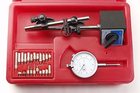
come on Chris, you've got to have one of these sets to use to measure deflection
Attached image(s)
Posted by: Racer Chris Dec 17 2005, 06:36 AM
Mike,
I have a dial indicator and mag base but not all those tips. I'm not really a machinist after all. 
Fine instruments aren't necessary to measure the trailing arm flex anyway. You can watch the movement and see exactly what is happening.
A stock trailing arm definitely isn't stiff enough for a competition car running on slicks.
Posted by: 9146986 Dec 17 2005, 09:00 AM
I saw one of the 1997 GT1 chassis on a deflection dyno at the Wiessach facility, and they had around 40 dial indicators at different places on the chassis. Forget about any photos, strictly verbotten (sp), and they probably would have shot you on the spot.
Al Swanson has run this part on a computer modeling program where he works (can't tell you that either  ), and found that welding the so called stiffeners actually weakend the the part, primarily due to annealing the steel.
The other consideration would be the bushings used. IMHO any stiffening would be mute with anything less than solid bushings, for obvious reasons.
I've always thought the tubing through the trailing arm would be the best way to go.
Posted by: Brett W Dec 17 2005, 09:13 AM
Now you are seeing the reason why many professionally developed racers are using a different, custom trailing arm. You can bandaid the stock part or you can build a much stronger yet lighter custom part.
The only reason to keep the stock trailing arm is a class rule that says you can't change it.
For a race car I would completely eliminate the bushings. Run a monoball or rod end. Look at Blakewell's car and Sheridan's car.
Here is Blakewell's setup. This is a Preston built chassis. He has a custom rear trailing arm but I don't have a picture of the arm.
Attached image(s)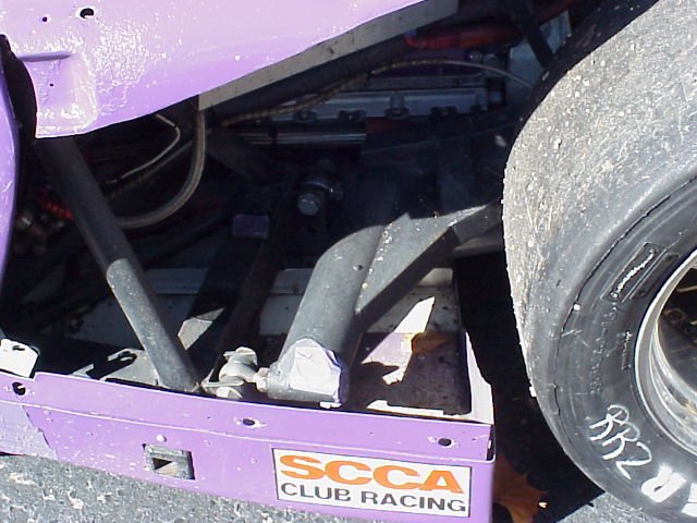
Posted by: Thorshammer Dec 17 2005, 10:49 AM
I have'nt seen this thread until this morning, but wanted to add some comments.
Chris and I started talking about this because som eof the info we have found for 914's seems at times to be untrue. People have done things for different reasons and many are not known. Such as The outer (stock) pick up point piece is extremely flexible, Chris has a stronger piece, I used it it works well. Why some people use a trailing arm stiffening kit and others do not. Here are the things we want to know:
-How much does a standard trailing arm twist in degrees of deflection when we load it near max load that we might see with slick under racing conditions.
. Only flaw I can see in Chris's methodology is maybe we have under or over estimated the load at the wheels. It also has a lever that would act upon the trailing arm, the Wheel. 11.75inches from the centerline. So we really need to make sure we've thought that through.
-How much lateral deformation when a max cornering load is applied. Meaning doe the arm bend thowards the transmission when we load it and if so how much.
-Where does it bend or Twist
-How does a trailing arm that is stiffened using the typical weld on plates perform to the same tests.
-Where can the arm be properly strengthend while adding minimal weight. Keeping in mind that some bending can be advantageous in gaining car "feel" at the limit. Same with Chassis twist, if its too stiff it looks good on paper but does not give the driver any feel and therefore be difficult to drive at the limit.
These are the problems we (Chris) are trying to solve.
Erik Madsen
Posted by: groot Dec 17 2005, 12:11 PM
| QUOTE (Thorshammer @ Dec 17 2005, 08:49 AM) |
| -How much lateral deformation when a max cornering load is applied. Meaning doe the arm bend thowards the transmission when we load it and if so how much. |
All very good stuff!!
Eric's question is very important. If you guys could apply to load at the tire contact patch you'd greatly enhance your investigation. Chris's current fixture measures the largest component and it's a great start.
Chris, if you could modify your fixture to apply the load at the contact patch so you get that additional force (bending) and then you could measure the trailing arm and then measure it again on the vehicle. Then you could determine what percentage of the compliance is associated with the trailing arm and how much compliance is associated with the chassis. That would be sweet.
I ran a crude version of this and decided to start over with a new trailing arm (and for some other reasons, too).
Keep it up, it is great when science is applied to making things work better!!!
Posted by: Thorshammer Dec 17 2005, 12:20 PM
Something else I haven't thought about is the amount of spacers on the wheels possibly changing the criteria. I run almost 40 mm of spacers in the rear. This may change the information, but for the time being, we will at least have some relative data, and that will be useful.
Erik
Posted by: SpecialK Dec 17 2005, 01:15 PM
Quick 
Is Erik's and Chris' race E-Prod?
If so, it's scheduled for 4 am Monday morning.
Now, back to your regularly scheduled 914 component testing...
Posted by: ChicagoChris Dec 17 2005, 02:04 PM
This is great and even though he hasn’t yet done the experiment I have been learning a lot from the discussion. But it feels like people are making this mole hill into the mountain.
I don’t get the impression that it is important to know every force, in every direction, to the .001? If the goal of the experiment is to know all the forces and how each surface of trailing arm reacts then ok. But if the purpose of the test is to get a practical way to strengthen the trailing arm against twisting force then I say he is right on.
Personally I am anxious to see what he finds.
![popcorn[1].gif](http://www.914world.com/bbs2/html/emoticons/popcorn[1].gif)
Posted by: bondo Dec 17 2005, 02:58 PM
Am I correct in assuming that 1 degree of deflection is no big deal for a street car?
As for race cars with big slicks, what kind of deflection are you shooting for? Is 1 degree 2 times too much? 10 times?
I love this stuff, I can't wait to see the proposed solutions and the results of testing them.
Posted by: Racer Chris Dec 17 2005, 03:22 PM
OK
I did some more experiments this morning.
The first thing I did was to rotate the trailing arm vertical so I could easily apply a load to induce lateral deflection. I was all alone so I couldn't make accurate measurements but the deflection is similar to the twisting deflection under the same loads. If anything it was slightly less. Personally I don't think lateral deflection is a problem as I am pretty sure the force component in that direction is much smaller.
I thought about my setup for a long time before actually assembling anything. Even though it appears to make significant compromises compared to what happens in the real world I am pretty sure it would be tough to make a major qualitative improvement over what I have. However making quantitative improvements wouldn't be too hard. I don't know if the load I am using is correct, and a digital level isn't as accurate as a dial indicator. OTOH, that is the same digital level I use to set up the suspension on the car and I am really only after comparative data, not detailed design analysis.
Since I was working alone I decided to standardize my forces and make it possible to read the level while under load. That meant I replaced my body weight on the lever arm with a stack of steel pieces adding up to about 220 lbs. The only shortcoming to this method is I can't observe the deflection as it occurs. I can only read the level to see the final effect. Good enough for now.
So I repeated yesterday's test with my standardized load and measured a deflection of 1.1 degrees.
Next I replaced the trailing arm with a boxed trailing arm and the deflection was 0.8 degrees under load.
Finally tested my idea for a reinforced trailing arm. Using just on piece of sheet steel that weighed 4 ounces and measured approximately 3x4 inches I was able to make an equivalent improvement to just 0.8 degrees of deflection on the original trailing arm. That compares to about 2 lbs of sheet metal used for a boxed arm, and a corresponding smaller amount of welding which means less distortion of the trailing arm.
Posted by: Racer Chris Dec 17 2005, 03:27 PM
Am I correct in assuming that 1 degree of deflection is no big deal for a street car?
You will never load the suspension enough to reach one degree of deflection in a stock based street car. These values only apply to race cars on sticky tires.
what kind of deflection are you shooting for?
I would like to cut the deflection by 50%.
But if the purpose of the test is to get a practical way to strengthen the trailing arm against twisting force then I say he is right on.
Posted by: jhadler Dec 17 2005, 03:28 PM
Great project Chris!
I'm really interested in the results.
I'd really like to know where the most flex occurs, and in what axis. Does the arm bend more toward the transaxle? Or does it twist more? Where is the weakest link? The bushings? The mounts (inbaord and outborad)? The arm itself?
Keep the good info coming!
-Josh2
Posted by: Racer Chris Dec 17 2005, 03:35 PM
| QUOTE (Thorshammer @ Dec 17 2005, 01:20 PM) |
| Something else I haven't thought about is the amount of spacers on the wheels possibly changing the criteria. I run almost 40 mm of spacers in the rear. This may change the information, but for the time being, we will at least have some relative data, and that will be useful. Erik |
The amount of wheel spacers is immaterial. All that matters is the location of the contact patch. Not only that, within the range we are working on our cars small changes to the geometry will have correspondingly small effects on the forces applied.
Posted by: Racer Chris Dec 17 2005, 03:40 PM
I'd really like to know where the most flex occurs, and in what axis. Does the arm bend more toward the transaxle? Or does it twist more? Where is the weakest link? The bushings? The mounts (inbaord and outborad)? The arm itself?
Well, on a race car with hard bushings and a reinforced outer mounting bracket 95% of the flex occurs in the box section of the trailing arm. I am fairly certain that most of the flex is twist and only a minor component is lateral.
The stock outer bracket, unreinforced, flexes quite a bit. Stock rubber bushings also flex quite a bit.
Posted by: Racer Chris Dec 17 2005, 03:45 PM
Here's a pic of the trailing arm in my bandsaw. The kerf of the saw is about 60 thousandths of an inch.
Attached image(s)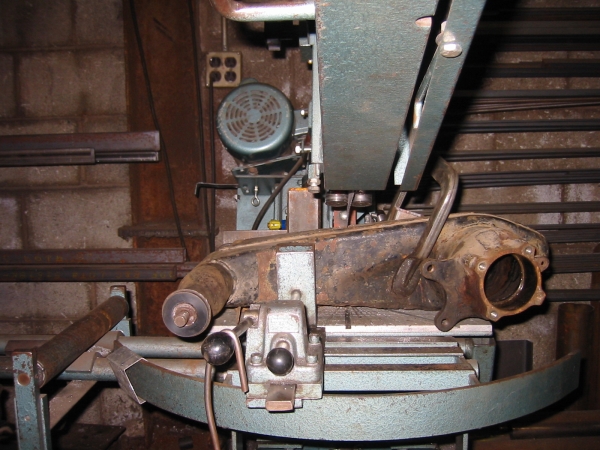
Posted by: Racer Chris Dec 17 2005, 03:48 PM
and here's a pic of the rewelded trailing arm. The metal piece I inserted is about .075" thick.
This had the same effect as adding the boxing kit but it still isn't enough for me. I plan to add one or two more things to get the flex down to 50% from the stock arm.
Attached image(s)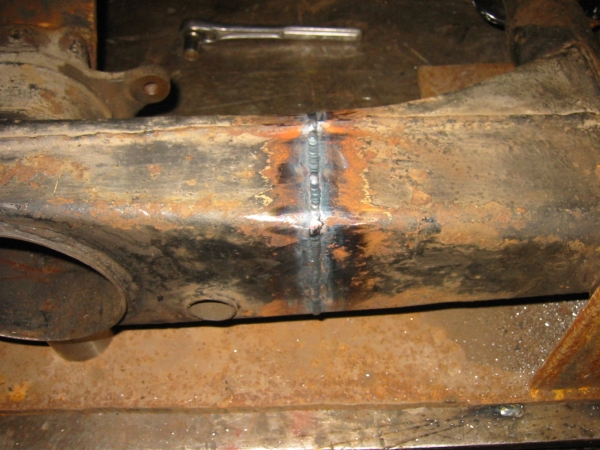
Posted by: Thorshammer Dec 17 2005, 04:08 PM
Chris,
If we move the contact patch outboard we will increase the twisting force becuase we change the fulcrum. I am pretty sure this is correct.
As for the discussion earlier, why we need to know specifics is, when setting up the static geometry and knowing the amount of chassis roll, as well as knowing the degree of deflection of the trailing arm, we can understand completely what is happening, and after the arm is strengthened and the camber and toe curves are known, we can better determine what the static camber and toe should be set at to get the best performance.
Other factors such as Roll center and instant centers will need to be taken into account as well, several people are working on this as well. I think Brett, Chris, Kevin and I are attempting to ensure this has been thoroughly investigated and we have soild data and can prove the methodology. We have to ensure the stiffness of the chassis and components prior to altering other parameters or the feedback from the chassis will not be 100% accurate. We know D Finch alters the trailing arms, and Kevin has a stunning idea that may bear fruit, but we will have to test to make sure. If his season starts this year like last, he will need studded tires and a plow on the front of that thing.
More later....
Erik Madsen
PS: EP is me and Kevins race at 4:00am which is only 1 am for you west coast guys.
Posted by: TimT Dec 17 2005, 04:21 PM
Chris thats EXACTLY how I imagined reinforcing the trailing arm. I thought of a way to get reinforcement inside the trailing arm without cutting the arm in half, I may try it on a damaged arm I have laying around.
Posted by: ChicagoChris Dec 17 2005, 04:35 PM
Ok.. Which interior surface did you reinforce?
Did you do the reinforcing to the arm you first tested or to a different arm?
Posted by: Thorshammer Dec 17 2005, 04:40 PM
This is a piece of metal that is welded between the two halves.
Tim,
Chris and I have discussed two different methods, one is what Chris has done, next we want to try cutting slots at and angle so that the trailing arm can be triangulated by three peices. This should increase the torsional rigidity to what we are looking to do. Then we have another to reduce the lateral bending moment. We will see what is needed.
Erik
Posted by: TimT Dec 17 2005, 04:51 PM
My thoughts were to cut slots also, and insert reinforcement and weld it in place. I though of doing it in 2 or 3 places.
Also the distance of the conact patch from the cl of the training are does matter. If you have the wheel spaced out very far, you increase the fulcrum that is acting on the trailing arm. It may not be a significant amount, but I dont think it should be neglected. I am going to try and crunch some numbers later and see what I come up with.
Posted by: ChicagoChris Dec 17 2005, 05:12 PM
OK.
Posted by: Racer Chris Dec 17 2005, 05:16 PM
If we move the contact patch outboard we will increase the twisting force becuase we change the fulcrum. I am pretty sure this is correct.
The amount of wheel spacers you use is largely due to the specific wheels you use. That's why I said it doesn't matter how thick they are. My wheels are offset differently so I don't need much wheel spacer.
However, EP allows you to have wider rear track which does affect the loads. I just don't think the distance is great enough to alter the methodology of what we are doing.
While I gree that cutting slots is the easy way to accomplish this I want to be able to alter the geometry at the same time. What I need next is the best location to add more stiffeners.
Posted by: Racer Chris Dec 17 2005, 05:17 PM
| QUOTE (ChicagoChris @ Dec 17 2005, 05:35 PM) |
| Did you do the reinforcing to the arm you first tested or to a different arm? |
same arm as in the first test
Posted by: McMark Dec 17 2005, 05:26 PM
Would it be more advantageous to weld a plate non-perpendicular to the centerline of the boxed section? i.e. 45 degrees off in two axis?
Posted by: r_towle Dec 17 2005, 05:41 PM
I thought you were busy.
Really looks great...
Have you given any thought to carbon fiber re-inforcement???
Not sure of a good structural way to bond it to steel, but this concept is being field tested on old bridges that need additional structural repairs...just a thougt
Rich
Posted by: rick 918-S Dec 17 2005, 06:14 PM
| QUOTE (McMark @ Dec 17 2005, 03:26 PM) |
| Would it be more advantageous to weld a plate non-perpendicular to the centerline of the boxed section? i.e. 45 degrees off in two axis? |
I was thinking the same thing Mark.
Posted by: Brett W Dec 17 2005, 07:37 PM
OK, you go to all the trouble to fix the flexible trailing arm. That is good. But you don't solve the problem of the moving roll center caused by your toe and alignment changes. This is another reason to build a different trailing arm.
I am on this now and hope to have some data by Monday.
Posted by: rick 918-S Dec 17 2005, 07:53 PM
Posted by: Dave_Darling Dec 17 2005, 08:14 PM
Chris, thank you very much for doing this testing, and for sharing the results with us!! It is fascinating reading.
--DD
Posted by: Bleyseng Dec 17 2005, 08:18 PM
Yes, its interesting but... I like Muellers idea for tools to measure with instead of that level.
Posted by: Mugs914 Dec 17 2005, 09:30 PM
This is one of the best threads I've seen here! Thanks for the effort and for sharing the results Chris! 
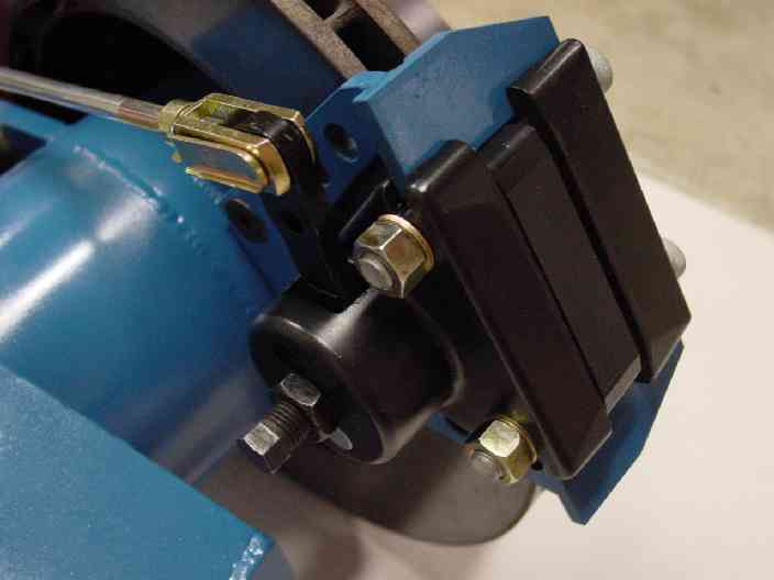
Here is the way we reinforce trailing arms. It isn't an original idea and most of you have probably seen it before, but here's a pic just in case. Its a 'tubular" method...
The tube goes from the bearing carrier diagonally through both sides of the arm. Triagulates and stiffens the walls of the arm in one shot.
Never have tested one, maybe we should send one out to you so it can be compared to others on the same rig. It would be nice to know if we are accomplishing anything....
Attached image(s)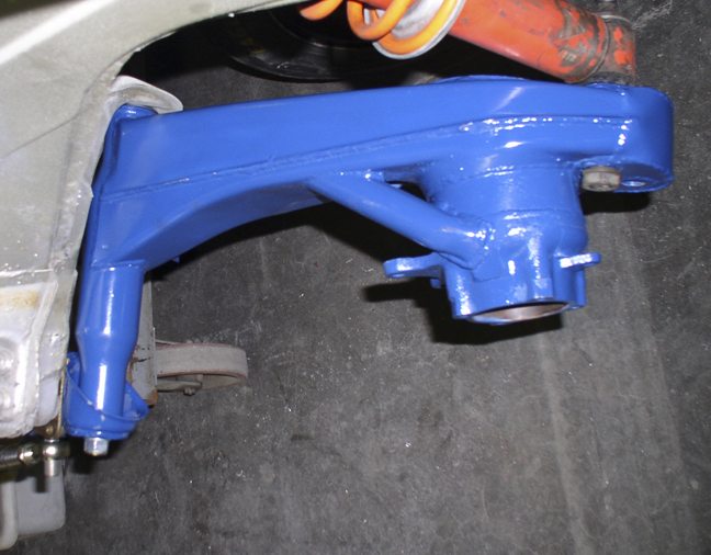
Posted by: Mugs914 Dec 17 2005, 09:32 PM
Here's a shot that shows where the tube comes through the inboard side.
Attached image(s)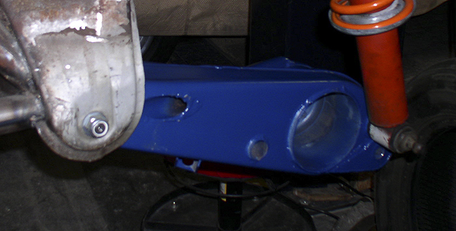
Posted by: Mugs914 Dec 17 2005, 09:33 PM
Outboard side...
Attached image(s)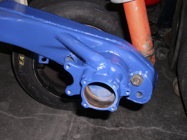
Posted by: McMark Dec 17 2005, 10:04 PM
That arm has an option for increased shock travel? Am I interpreting that correctly?
Posted by: Aaron Cox Dec 17 2005, 10:07 PM
| QUOTE (McMark @ Dec 17 2005, 09:04 PM) |
| That arm has an option for increased shock travel? Am I interpreting that correctly? |
good eye....
stock length shock on a lowered car - resulting in useful travel vs bottoming it out.....
Posted by: rick 918-S Dec 17 2005, 10:31 PM
Oooo! shock travel= cool! 
Posted by: Mugs914 Dec 18 2005, 12:58 AM
| QUOTE (Aaron Cox @ Dec 17 2005, 08:07 PM) | ||
good eye.... stock length shock on a lowered car - resulting in useful travel vs bottoming it out..... |
Yup, bottoming out bad...

This gives almost two inches lower and keeps the stock travel.
If anyone wants a set, let me know...
Posted by: Brett W Dec 18 2005, 01:03 AM
Why not just buy the shock with the right length?
Posted by: Racer Chris Dec 18 2005, 05:31 AM
| QUOTE (Brett W @ Dec 18 2005, 02:03 AM) |
| Why not just buy the shock with the right length? |
or raise the top perch.
Attached image(s)
Posted by: Racer Chris Dec 18 2005, 05:33 AM
| QUOTE (Mugs914 @ Dec 17 2005, 10:30 PM) |
| Never have tested one, maybe we should send one out to you so it can be compared to others on the same rig. It would be nice to know if we are accomplishing anything.... |
I'd be glad to do it!
Posted by: ein 6er Dec 18 2005, 08:56 AM
good stuff here guys!!! 
in the custom swing arm dept., here are a couple of shots of an arm on a twin turbo tube frame 914 i saw a pca club race at robeling road last year.
right side,
Posted by: ein 6er Dec 18 2005, 08:56 AM
left side
Posted by: ein 6er Dec 18 2005, 08:58 AM
right side
Posted by: DJsRepS Dec 18 2005, 09:18 AM
| QUOTE (TimT @ Dec 16 2005, 07:41 PM) |
| Put the level on the trailing arm, not the lever let all pieces be at rest, zero the level, given the odd profile of the trailing arm.. maybe some foam or balsa wood will be needed to make a suitable platform for the level the reason I say this is there is deflection/movement in the plate that you bolted to the bearing keeper In all testing and modeling are good... 1 deg at 1G wonder what they were designed for ? |
Right on Tim! totaly agree more accurate test results.
Make a rig on the arm to support the level.
Posted by: DJsRepS Dec 18 2005, 09:20 AM
Woah I replied to Tim's post before seing 5 pages here. A little too quick there.
Posted by: Brett W Dec 18 2005, 09:43 AM
That is Andy McNeal, I believe. That car is super bomb bad ass. Twin turbo 3.4 and fully custom tube chassis. I don't have a scanner so I can't scan teh 15-20 some odd pictures of the car.
Posted by: ein 6er Dec 18 2005, 10:14 AM
| QUOTE (Brett W @ Dec 18 2005, 07:43 AM) |
| That is Andy McNeal, I believe. That car is super bomb bad ass. Twin turbo 3.4 and fully custom tube chassis. I don't have a scanner so I can't scan teh 15-20 some odd pictures of the car. |
i don't know who's it is. it was being ran/maintained by a shop in N.C. IIRC it qualified with the fastest time of all there that day, but never raced.
Posted by: Mueller Dec 18 2005, 11:35 AM
strange idea to see where the twisting starts:
cover the trailing arm in a non-flexible coating such as plaster of paris or sheetrock mud....when dried, it should crack as soon as the twisting starts
I'm thinking that instead of covering the entire arm all at once, just do 6 inch sections or so at a time.....
Posted by: r_towle Dec 19 2005, 09:08 PM
so, is carbon fiber an option here..
Can it be effectively bonded to steel...
Rich
Posted by: Racer Chris Dec 20 2005, 05:29 AM
| QUOTE (r_towle @ Dec 19 2005, 10:08 PM) |
| so, is carbon fiber an option here.. Can it be effectively bonded to steel... Rich |
I suppose you could make trailing arms out of CF that would be quite stiff.
Dunno about trying to accomplish stiffening by bonding CF to a stock arm. A lot quicker to do a little welding.
Posted by: Bleyseng Dec 20 2005, 08:23 AM
you could just pour hot liquid sugar over it, that stuff when it cools will crack alot under movement.
Posted by: Racer Chris Dec 21 2005, 09:07 AM
Here's a diagram of what I intend to try next. Move the slice forward (to the right) about 3", and add a diagonal plate inside as well.
BTW, some further testing revealed that the pivot tube does flex outboard of where the box section attaches. I will investigate this in more detail as well.
Attached image(s)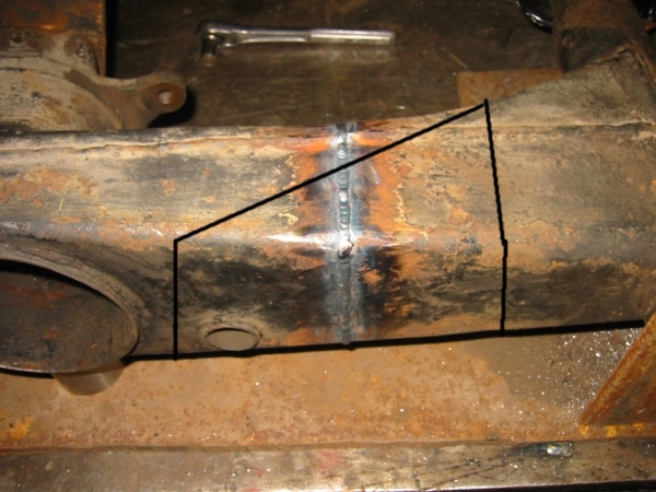
Posted by: r_towle Dec 21 2005, 09:13 AM
Chris, this looks great...though I would not trust my welding on that one....
It does make me think though...
In the longitudinal, where the heater pipe penetrates the inner long, could this type of bracing assist in stiffening that area..
I know in a pure race car, that pipe can be deleted...
But in a street car with heat, could you put plates all around that pipe and connect the inner and outer long in that area to assist in stiffening the car?
Keep in mind...im going in soon...as soon as my kids car is off my beloved jack stands...
Rich
Posted by: mrdezyne Dec 23 2005, 03:47 PM
Just waiting for more! Good reading....
Posted by: Brando Dec 23 2005, 03:56 PM
I'm wondering what the deflection is with stock bushings Definitely good info in this and I can't wait to see how a reinforced trailing arm compares.
Posted by: Dead Air Dec 23 2005, 05:40 PM
This is a cool thread. I'm just thinking out loud and sorry about the rough graphics.
The "focus" of the stress would move out board and not be a static force?
Uhhm...
The twisting force would change relitive to the trailing arm as the approach changed. Not just the Ft. lbs.
Do I make any sense?
Attached image(s)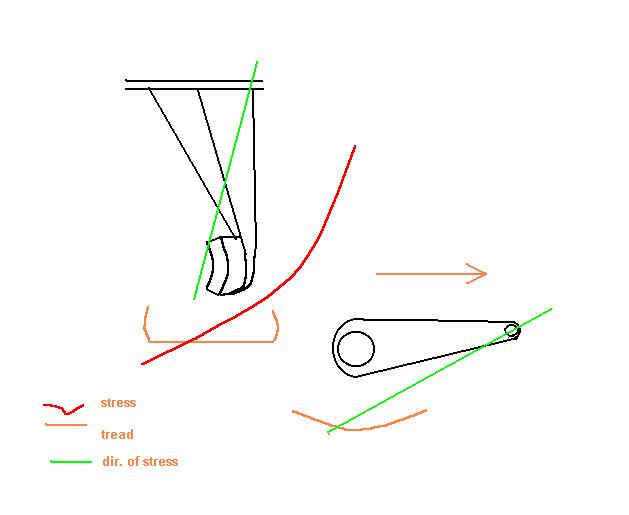
Posted by: SpecialK Dec 23 2005, 08:08 PM
| QUOTE (r_towle @ Dec 19 2005, 09:08 PM) |
| so, is carbon fiber an option here.. Can it be effectively bonded to steel... Rich |
I've got Boeing's best composite engineers (three of them actually) working on this very question. I posed the question to Jim, a senior engineer at Boeing (and a motor-head at heart), about which would be the most structurally sound way to stiffen my 914's inner longs with the 900' roll of uni-CF I got recently.....lay-up and bag the material directly to the longs, or make molds (or use a parting agent between the longs and composite) and bond the composite long stiffeners to the longs using a high-strength structural adhesive. He loves this kind of shit (anything car related) and said he was going to get with a couple of other guys on the subject and "crunch some numbers"
. Personally, I think the HSSA method would be stronger than laminating directly to the steel, but either method would virtually eliminate corrosion from forming between the long (or swing-arm in this case) and stiffener. I may just make a couple of test billets while I'm off for Xmas break utilizing both methods, and abuse them until something cries "Uncle".....
Posted by: kwales Dec 23 2005, 10:41 PM
Kevin,
I think the reason that people don't glue to steel is corrosion. A rust bubble can place a lot of stress on a glue joint and would probably enlarge until it caused delamination- right when you don't want it.

I have done a lotta aircraft structural type work with structural epoxy and rivets but aluminum doesn't form rust bubbles as readily as steel. The rivets are used both as reinforcement and as a means of squeezing the glue as thin as possible (max strength). Glue joint strength is primarily dependent on adhesive strength and glue area.
Ken
Posted by: jhadler Dec 28 2005, 04:58 PM
Hey Chris,
Any new data on the trailing arm flex experiment?
-Josh2
Posted by: Racer Chris Dec 29 2005, 06:28 AM
Hey Chris,
Any new data on the trailing arm flex experiment?
-Josh2
Yes, just a small amount of new info.
I was measuring the flex with the digital level mounted on my lever arm. After further examination it appears that there is measurable flex in the mounting end of the lever, so I moved the level to the brake mounting ears on the trailing arm. This change subtracts 0.3 degrees from the previous measurements.
Also my latest reinforcement, as described in the last picture, did not reduce the flex any more than a single bulkhead in the middle of the trailing arm. My next test will be two bulkheads, parallel to each other, several inches apart.
Posted by: brant Dec 29 2005, 09:10 AM
Chris,
did the measurement changes (the .3 degrees) subtract from both the before and after?
so .7 before
and .5 after
brant
Posted by: J P Stein Dec 29 2005, 11:37 AM
How's about filling the arm with some hi-density foam.
The problem would cleaning the inside of the arm well enuff to have the stuff adhere.....plus selection the right foam. I don't know what is available.
Molten aluminum poured in would be gud too.......then start drilling holes.
Posted by: goose2 Dec 29 2005, 11:52 AM
| QUOTE |
| How's about filling the arm with some hi-density foam. |
Not as crazy as it sounds....we once filled all the cavities in a bugeye racecar with foam and got a noticible increase in chassis stiffness. We abandoned the idea later though...when we had to do some welding on it
Another possible filler would be a lightweight epoxy mix with lots of micro-baloons.
Posted by: J P Stein Dec 29 2005, 03:32 PM
| QUOTE (goose2 @ Dec 29 2005, 09:52 AM) |
| Not as crazy as it sounds....we once filled all the cavities in a bugeye racecar with foam and got a noticible increase in chassis stiffness. |
I may be crazy, but I ain't stupid.
If a guy could come up with sumthing to pour in and not add more than 4-5 lbs of weight you'd be in fat city.
Epoxy: maybe half full & rotate along the long axis till dry.
Maybe add an inch of wall thickness.
Thinking outside the box (NPI)
What else do I have to do while sanding off orange peel?
Posted by: Brett W Dec 29 2005, 06:09 PM
There are several companies that sell a foam injection kit for cars. Sport and Compact did a project Miata with one of the kits. I know all of the new Ford SUVs have a two part foam injected into the hollow areas on the chassis. There is a substaintial difference in the harmonic resonance levels as well as chassis stiffness.
Many of our chassis are fairly clean on the inside of the longs and other areas. You could do this and probably pick up some serious reductions in NHV. The problems are when you go and put this in rusty areas it will not bond, nor will it stop the rust. Also if you do this to a chassis it will cause problems if you try and weld over it. Poof, your car burns to the ground.
Otherwise it would be a good upgrade. You could acid dip the arms and then inject them with foam. Won't five substantial improvements in just the arms but it will help out a little.
Posted by: Racer Chris Dec 29 2005, 07:29 PM
Chris,
did the measurement changes (the .3 degrees) subtract from both the before and after?
so .7 before
and .5 after
brant
That's about right, except I am using 1.1 for the original stock measurement and I get 0.8 with the level attached to the brake caliper mount (ie. vertical).
Today I added a second bulkhead to the most recently modified trailing arm. There was no further improvement - still a deflection of 0.5 deg.
I think I'll try adding some Chrome-Moly sheet in selected areas next.
Posted by: Racer Chris Dec 29 2005, 07:34 PM
| QUOTE (J P Stein @ Dec 29 2005, 04:32 PM) |
| If a guy could come up with sumthing to pour in and not add more than 4-5 lbs of weight you'd be in fat city. |
4-5 lbs???
JP, I'm barely willing to add one pound.

Posted by: J P Stein Dec 29 2005, 07:43 PM
| QUOTE (Racer Chris @ Dec 29 2005, 05:34 PM) | ||
4-5 lbs??? JP, I'm barely willing to add one pound. |
I hear ya, I ground down my trailing arms castings, cuf off the ears for the backing plates and all them little support ears to get 2-3 lbs off them.....even painted them yellow (YPAF, ya know
). But I'd put some back on to stiffen em'.....but not them fishing lures "they" sell for the job.
Posted by: Racer Chris Dec 31 2005, 02:07 PM
I had time for one more trial before 2005 ran out.
This was a continuation of the modifications to the first trailing arm I upgraded. This one already had the bulkhead added to the center of the box section and a fancy gusset between the box and the pivot shaft tube.
My observations indicated that the pivot shaft tube was flexing significantly, after the box section was stiffened, and the gusset didn't stop that. I decided to add a reinforcing layer over the exposed front side of the pivot shaft tube, as shown in the picture. The overlay is .065wall mild steel, a half section of 2 1/2" od tube about 7" long.
The original trailing arm flexes about 0.8 deg. under stress.
With the bulkhead added the flex drops to about 0.5 deg.
The gusset didn't stiffen the trailing arm noticeably - at least not in torsion.
The tubular overlay resulted in a reduction of the twisting to 0.4 degrees.
The trailing arm "feels" stiffer when I put my weight on the lever and is 50% stiffer than stock by the numbers.
I will probably use these three reinforcements (that weigh less than 16oz.) on my race car's trailing arms, but there is one more area where I want to focus my attention.
The part of the trailing arm that is pocketed to make clearance for the brake caliper bothers me. I want to fill that in so the pocket no longer exists. I think there is still room for a front caliper after filling in that area.
Attached image(s)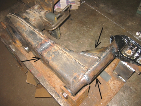
Posted by: Travis Neff Dec 31 2005, 02:14 PM
Looks great as usual Chris, good job!
Posted by: slivel Dec 31 2005, 02:35 PM
This is where my arm cracked multiple times. After boxing the arm it is the weakest point it seems. The fix was to press in a piece of mild steel tubing (same size as my roll cage, I think). The arm was drilled in multiple spots and then welded to fix the pressed in tube to the arm. This seems to be a good fix - I do stress my suspension severely andso far no cracks. The additional advantage is that the weight that you add is mostly sprung weight and not unsprung as it would be if it were far out on the moment arm of the suspension. I am sure that this also minimizes flex in this area.
Attached image(s)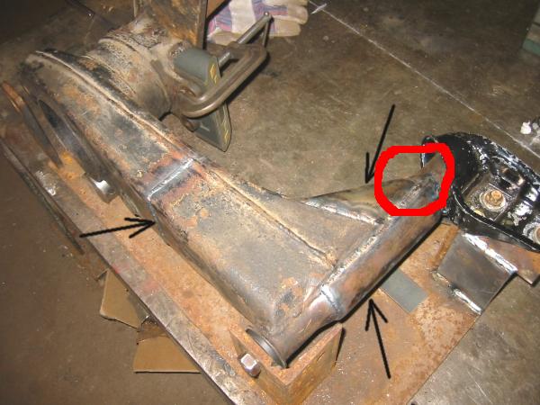
Posted by: Al Meredith Dec 31 2005, 09:03 PM
Chris great stuff! thanks. My $.02 . Have you thought about using a lazer pointer witha magnetic base on the part you are monitering. Then put a piece of sheetrock on the ceiling to put the bean on. This way you would see deflection in two axis at the same time. Comments? Al
Posted by: brant Dec 31 2005, 09:12 PM
So Chris,
now that you about have it nailed down.. one thought still sticks in my head.
how much negative camber can you easily dial in?
would it be basically limit-less?
I don't know that I need any more, but it makes me think......
here is what I think: "too bad I have monoballs at this point, its just not worth new wheel bearings and re-doing the monoballs."
two more questions sir.
since you have the arm with the old style kit handy.
how much does that one weigh, and how much total does your lovely new one weigh?
do they both have similar bearings and pivot shafts (weight wise)
and finally,
I lost track a tiny bit.
with the 2nd style of measurement, what is your measurement for an old style reinforced arm. Is it also at .5 deflection now? (I know at one point it was .8, but I'm not clear if it was remeasured when you switch measurement modes)
brant
Posted by: URY914 Dec 31 2005, 09:14 PM
| QUOTE (Al Meredith @ Dec 31 2005, 07:03 PM) |
| Chris great stuff! thanks. My $.02 . Have you thought about using a lazer pointer witha magnetic base on the part you are monitering. Then put a piece of sheetrock on the ceiling to put the bean on. This way you would see deflection in two axis at the same time. Comments? Al |
Good idea, Al.
Paul
Posted by: Racer Chris Jan 1 2006, 09:45 AM
| QUOTE (Al Meredith @ Dec 31 2005, 10:03 PM) |
| Have you thought about using a lazer pointer |
Thats a great idea Al.
I have a laser pointer so I will try it.
Posted by: Racer Chris Jan 1 2006, 09:52 AM
| QUOTE (brant @ Dec 31 2005, 10:12 PM) |
| how much negative camber can you easily dial in? |
I can make outer pickup brackets that change the starting camber - more positive or more negative.
| QUOTE |
| how much does that one weigh, and how much total does your lovely new one weigh? |
| QUOTE |
| with the 2nd style of measurement, what is your measurement for an old style reinforced arm. |
Posted by: brant Jan 1 2006, 02:59 PM
Chris,
I think this is an awesome product/service from CFR!
-50% stronger than stock and 20% stronger than the other "kit"
-I'm guessing 4lbs lighter (mostly unsprung weight)
-and available with an extra -1degree of camber (or other amounts)
sounds pretty hot to me!
brant
Posted by: Racer Chris Jan 4 2006, 07:32 PM
Here's some weight data.
Stock trailing arm: 15lb, 5oz.
Boxed trailing arm: 18lb, 2oz.
My reinforced trailing arm: 16lb, 5oz.
For reference, a pivot shaft with bushings weighs 1lb, 8oz which is included in the above weights.
Posted by: Eric_Shea Jan 4 2006, 08:12 PM
When was the last time I read a 7 page thread? 
Awesome!
Chris, thanks a lot 
So, if I'm reading this right, a factory style stiffening kit is just under 3lbs. heavier (per side) and is 30% stiffer than stock?
Posted by: Racer Chris Jan 4 2006, 08:23 PM
So, if I'm reading this right, a factory style stiffening kit is just under 3lbs. heavier (per side) and is 30% stiffer than stock?
Yup. Actually more like 38%. (0.3/0.8)
More than half the weight of the boxed kit is unsprung.
No more than 4oz. of my design is unsprung, and is another 12% stiffer.
I got some info from a friend tonight. He modelled the trailing arm and did some FEA for me. I haven't had a chance to analyze the details but everything appears to agree with my empirical data.
Posted by: Eric_Shea Jan 4 2006, 08:37 PM
| QUOTE |
| More than half the weight of the boxed kit is unsprung. No more than 4oz. of my design is unsprung, and is another 12% stiffer. |
No, no... don't get me wrong. You're thing is the cat's ass, especially for guys in your arena that want to shed all the oz.'s they can.
I was just curious because I installed one years ago and was told that it was worthless, etc. Now I'm OK with the decision... it could be lighter and stiffer but frankly I'm just glad it helps and doesn't hurt. For me 6lbs isn't that bad. I saved that with my S-Calipers.
Thanks again. Killer thread. This needs to be book marked for a "Classic" for sure
Posted by: TimT Jan 4 2006, 08:54 PM
| QUOTE |
| I got some info from a friend tonight. He modelled the trailing arm and did some FEA for me. I haven't had a chance to analyze the details but everything appears to agree with my empirical data. |
hehehe
I have the same data... Im looking at it now... I dont see any hotspots which is a good thing when you do a wireframe FEA
One thing that I may offer is that there are mulitple forces happening at once on a trailing arm.. not just torsion .
In order to investigate this further we should agree on some nomenclature, call X the horizontal plane, Y the vertical plane. etc
Posted by: Racer Chris Jan 4 2006, 09:11 PM
No, no... don't get me wrong. You're thing is the cat's ass, especially for guys in your arena that want to shed all the oz.'s they can.
I didn't think you were giving me a hard time. I just thought it was a good intro for me to restate the facts.
One thing that I may offer is that there are mulitple forces happening at once on a trailing arm.. not just torsion .
I also realize that my lever arm applies the force at 90 degrees to what would be required to measure the lateral effect but it was convenient to do it this way. Also the FEA says it doesn't matter whether the rear of the trailing arm is supported at the bottom as I did or at the shock mount, for the torsional measurements.
Posted by: Pinepig Jan 4 2006, 09:14 PM
New guy here, I LOVE this forum, you guys rock.
If you want to watch it flex put a cable on the end of the pipe that you are using to load the trailing arm and hang your 220lbs on there, set them on a floor jack and just let it down while you watch.
Posted by: Racer Chris Jan 4 2006, 09:14 PM
| QUOTE (TimT @ Jan 4 2006, 09:54 PM) |
| hehehe |
Tim, guess who did the FEA for me. You know him from the PP racing forum.
john luetjen
Posted by: Racer Chris Jan 4 2006, 09:20 PM
| QUOTE (Pinepig @ Jan 4 2006, 10:14 PM) |
| If you want to watch it flex put a cable on the end of the pipe that you are using to load the trailing arm and hang your 220lbs on there, set them on a floor jack and just let it down while you watch. |
That would work great except my weight consists of 12 pieces of steel of varying shape and size (plates, sq bars, rd bars). If I was into freeweights I could do what you suggest.
What I really like doing is having a friend bounce up and down on the lever while I watch the trailing arm closely.

Posted by: TimT Jan 4 2006, 09:20 PM
Chris,
Im getting more concerned with the trailing arm mounts.... than the trailing arm itself... You obviously have by intuition, good ole common sense, and some inate engineering prowess cured a problem with the trailing arms in high load situations..
Now we bolt these arms back to the 914 tub.. I dont know the GCR but how much are you allowed to reinforce the pickups...
kudos to you and your development of these cars...
Ill play around and try and determine lateral forces
Posted by: TimT Jan 4 2006, 09:25 PM
Chris I know John did the FEA since he cc'd me in an email
John sent me the FEA based on he is a salesman not an engineer.. well Im an engineer, and John continues to impress me with his insights, and grasp of problems that face us..
Posted by: Racer Chris Jan 4 2006, 09:33 PM
| QUOTE (TimT @ Jan 4 2006, 10:20 PM) |
| some inate engineering prowess.. |


| QUOTE |
| how much are you allowed to reinforce the pickups... |
Posted by: Racer Chris Jan 4 2006, 10:05 PM
Chris I know John did the FEA since he cc'd me in an email
I shoulda known.

One thing the FEA didn't pick up is the amount of improvement from adding the bulkhead. Is that due to the wire frame model being different from sheet material or some other shortcoming of the software?
One piece of information that I have is a damaged trailing arm from the wheel being hit by another car. It buckled not far from where I added the bulkhead. I am guessing that the box tube dimples in that area during torsional force application as well, and the bulkhead prevents the dimpling. Adding more bulkheads had no additional benefit.
Posted by: jluetjen Jan 5 2006, 03:54 PM
OK. I'll stop lurking on this thread and post some pictures of the model -- without the bulkhead.
http://www.914world.com/bbs2/uploads/post-2-1136498067.jpg
Attached image(s)
Posted by: jluetjen Jan 5 2006, 03:55 PM
And from the back side...
http://www.914world.com/bbs2/uploads/post-2-1136498136.jpg
Attached image(s)
Posted by: jluetjen Jan 5 2006, 03:57 PM
And from the top... (Note that the displacement is exagerated)
http://www.914world.com/bbs2/uploads/post-2-1136498261.jpg
Attached image(s)
Posted by: jdogg Jan 5 2006, 04:43 PM
| QUOTE (Racer Chris @ Jan 4 2006, 11:20 PM) |
| What I really like doing is having a friend bounce up and down on the lever while I watch the trailing arm closely. |
Hey, I resemble that remark!
Chris, looks like you had brainstorm in another direction since I was there. Good stuff!!
Posted by: jluetjen Jan 5 2006, 05:25 PM
| QUOTE (Racer Chris @ Jan 4 2006, 08:05 PM) |
| One thing the FEA didn't pick up is the amount of improvement from adding the bulkhead. Is that due to the wire frame model being different from sheet material or some other shortcoming of the software? |
When I added the bulkhead, I used the same 2mm thick steel as I used for mostof the rest of the trailing arm model. While a bulkhead helps some, since most of the forces travel across the exterior of the arm, it's not going to be the best solution. Keep in mind that when modelling torsion bars, generally it doesn't make a big difference from a torsional displacement perspective if they are hollow or not since most of the forces travel across the exterior. This trailing arm really isn't much more then a stubby T-bar*. As you picked up with your experiments, most of the surface stress is in the area where the trailing arm's cross-section transitions from being an upright rectangle to being a laying down rectangle. Increasing the cross-sectional area of the trailing arm -- specifically in this area should yield the biggest improvement.
* Basic rule: The angular rate of a tube (in in/lbs/degree) is = (19700 * (OD^4-ID^4))/tube length. So if you were to generalize and say that the trailing arm is a 16 inch long tube with an OD of 4 inches (average) and an ID of (4 inches - (4mm or 3.84 inches)), then the rate of the trailing arm is 19700 * (256-217)/16 = 47.5k in/lbs/degree. If you separate it into 2 - 4 inch OD bars, one hollow bar of (16 inches - 2 mm (.08 inches) = 15.92 inches, and the other a solid bar of 2 mm in length, you get the hollow bar has a rate of 48k in/lbs/degree, while the solid bar has a rate of 63,040k in/lbs/degree. Combined using the formula 1(1/rate1 + 1/rate2) = total rate, we come up with a total spring rate for tube with a bulkhead of essentially... (wait for it!)... 48k in/lbs/degree! But, if you were to increase the OD of the the tube to 4.5 inches (still with an ID 4 mm less), you would get a rate of 19700 * (410 - 355)/16 = 68k in/lbs/degree. So you'll get much better results by increasing the cross-sectional area of the arm rather then adding internal bulkheads. This is what you did by adding the gusseting where the fabricated assembly attaches to the smaller tube.
Posted by: Racer Chris Jan 5 2006, 05:38 PM
| QUOTE (jluetjen @ Jan 5 2006, 04:54 PM) |
| OK. I'll stop lurking on this thread and post some pictures of the model -- without the bulkhead. |
I'm glad to see you over here John. Thanks for doing this for me!
In a previous life I was going to be a mathematician and I could have had this in hand with little more than a snap of the fingers. Instead I embarked on developing the weak side of my personality and now too much math gives me a headache.

| QUOTE |
| If you separate it into 2 - 4 inch OD bars, one hollow bar of (16 inches - 2 mm (.08 inches) = 15.92 inches, and the other a solid bar of 2 mm in length, you get the hollow bar has a rate of 48k in/lbs/degree, while the solid bar has a rate of 63,040k in/lbs/degree. Combined using the formula 1(1/rate1 + 1/rate2) = total rate, we come up with a total spring rate for tube with a bulkhead of essentially... (wait for it!)... 48k in/lbs/degree! |
Posted by: Porcharu Jan 5 2006, 05:46 PM
Something that might be interesting would be to load up the trailing arm in your rig and use a mic or a good set of calipers and measure across the arm and see if it is bulging or puckering (cross section) under load (compared to the unloaded condition.) If it was it would explain why the simple bulkhead works so well - "pucker facter reduction technology!"
Posted by: Racer Chris Jan 5 2006, 06:07 PM
| QUOTE (srbliss @ Jan 5 2006, 06:46 PM) |
| "pucker facter reduction technology!" |
lol, I like that!
It would probably take a while to isolate the location of maximum pucker but I expect that would be possible to measure a change there.
Posted by: jluetjen Jan 5 2006, 07:18 PM
| QUOTE (Racer Chris @ Jan 5 2006, 03:38 PM) | ||||
I'm glad to see you over here John. Thanks for doing this for me! In a previous life I was going to be a mathematician and I could have had this in hand with little more than a snap of the fingers. Instead I embarked on developing the weak side of my personality and now too much math gives me a headache.
|
OK -- I was never very good at arithmetic...
3 springs in series, 2 of them have a rate of 96,037 in/lb/degree, and one of them has a rate of 63,037,000 in/lb/degree. So the formula would be...
1/(1/96,037 + 1/96,037 + 1/63,037,000) = 47,982 in/lb/degree. So the essentially solid bulkhead contributes very little to the overall stiffness because it basically replaces .5% of the springs total length with a solid piece. At best I would expect it to reduce the overall spring rate by about .5%.
Or did I get my math wrong?
This weekend I'll try running a bulkhead diagonally through the arm (end to end) to see what it does. That may make the whole arm act like it is (more) solid.
Posted by: Racer Chris Jan 5 2006, 07:27 PM
Actually, I was thinking about this while I was making dinner, and I decided the reason was something else.
The formula for a torsion bar doesn't properly apply in this application. The wall thickness is so small compared to the od that non-linear deformation occurs from the amount of load applied. The sides of the box deform laterally. That''s where the "pucker factor" comes in. The bulkhead stops the puckering and actually makes the torsion bar formula more appropriate to predict the spring rate.
Posted by: jluetjen Jan 5 2006, 07:37 PM
OK. For all of the engineers out there-- what sort of forces cause "pucker"?
* Axial Load?
* Shear Y Load?
* Shear Z Load?
* Torsion Load?
* Moment Y Load?
* Moment Z Load?
Or any of the above as a stress?
I can model all of those with my software.
Posted by: Racer Chris Jan 5 2006, 07:59 PM
Could it be because the arm is square as opposed to round?
That causes the corners to stretch more than the sides since they are farther from the twist axis.
On body panels puckers occur when a part of the panel is stretched, like when it gets dented.
The difference is the trailing arm isn't stretched beyond the elastic limit of the steel, unless it gets hit by another car.
Posted by: TimT Jan 5 2006, 08:47 PM
John continues to impress...
I havent built the model put it through a FEA yet.. I have many things on my plate right now.. which are distracting me., I am working day to day, the hammer may drop tomorrow morning when I get to the office. And then its look for a new job
Im modernizing my 1918 home.. replacing windows etc..the furnace got flooded a few weeks ago....
The cross section of the trailing arm has everything to do with its ability to resist torsion and bending forces. Square sections and circular sections behave differently in regards to torsion and bending.
Posted by: Racer Chris Jan 5 2006, 08:55 PM
Square sections and circular sections behave differently in regards to torsion and bending.

Square is better in bending and round is better in torsion.
For torsion, having all the material equidistant from the axis is better.
For bending, a square section puts more material in tension/compression at a greater distance from the centerline.
Posted by: jluetjen Jan 6 2006, 05:33 AM
True. But if we have a hollow "bar" X (square or round section) which is too flexible in torsion and in flex -- what to do? ( 'Just questioning the fundimentals...)
It would seem that in decreasing order of effectiveness our choices are...
1) Make it solid and thicker
2) Filling it in (or replacing it with a unit with a solid cross section. BTW -- This is what Porsche did with the 911 trailing arms when they converted to cast aluminum pieces in 1974. And the 911 is actually a better situation since the trailing arm is triangulated by the spring plate which is a feature the 914 doesn't have room for.)
3) Increase the cross section
3a) Increase the cross section across the largest percentage of it's length that you can
4) Increase the wall thickness
5) Add latetudinal bulkheads.
The question is where do longitudinal bulkheads appear on the list? That's what I hope to test.
Posted by: michel richard Jan 6 2006, 06:27 AM
I am not an engineer nor a mathematician etc . . .
Still, my own empirical experience has been that No5 in the list above should be much higher in that list, at least as regards tortional flex.
Posted by: crash914 Jan 6 2006, 06:37 AM
Again going back, what is the effect of adding the hollow tube from the trailing arm to the pivot arm? This should resist the lateral forces..
Posted by: jluetjen Jan 6 2006, 07:41 AM
| QUOTE (michel richard @ Jan 6 2006, 04:27 AM) |
| I am not an engineer nor a mathematician etc . . . Still, my own empirical experience has been that No5 in the list above should be much higher in that list, at least as regards tortional flex. |
When I orginally modeled the arm for just tortional flex (-1000 lbs Z), it didn't flex by much at all. But based on input from this thread I tried modeling it with all of the forces that would be influencing it while cornering -- so -1000 lbs X (braking), -1000 lbs Y (lateral cornering forces) and 1000 lbs Z (roll), all at the same time. This resulted in the deflection shown below. This is about 13% more the tortional flex of earlier case (Z deflection), and about 1000X the deflection in the Y direction -- which impacts Toe.
Specifically...
Global Coordinate Displacements/Rotations (in inches)
Node X-Displ. Y-Displ. Z-Displ. X-Rot. Y-Rot. Z-Rot.
First, Just 1000 lbs -Z, no bulkhead.
232 1.027E-05 -4.044E-05 -1.355E-03 -3.071E-04 6.046E-05 2.470E-06
Now, same model, but with all 3 forces inflicted upon it.
232 -1.035E-03 -1.537E-02 1.325E-03 3.710E-04 -6.441E-05 1.560E-03
Now the model with the bulkhead and all 3 forces.
232 -1.034E-03 -1.534E-02 1.310E-03 3.533E-04 -6.467E-05 1.560E-03
Going back to this picture, note that the arm is bending across it's entire length (and exagerated by 100X in the illustration). Adding a latitudinal bulkhead across just 1% or 2% of it's length just isn't really going to make much difference in this situation.
I suspect it will when the forces become high enough for significant distortion to occur in the outer skin or deformation in the entire structure. Basically just short of the structure's failure. But just 1000 lbs here or there will only result in a gentle bend across it's entire length as each individiual element (molecule) deforms by 1% or 2%.
I don't think that my model is an exact replica of a 914's trailing arm, but I think that it's close enough that it can give us some ideas of how and why the arm reacts the way that it does.
crash914; I'll also try modeling what you described this weekend.
Posted by: Racer Chris Jan 6 2006, 09:23 AM
I tried modeling it with all of the forces that would be influencing it while cornering -- so -1000 lbs X (braking), -1000 lbs Y (lateral cornering forces) and 1000 lbs Z (roll), all at the same time.
That's a little extreme. Working with a friction circle you would find the car looses rear grip well before this situation occurred.
Real world - a torsional force of greater than 1000 ft-lbs results in less than 1 degree of twist. I didn't measure the lateral deflection with the same load but I did observe it and estimate it to be also on the order of 1 degree.
John, I can't see in the drawings where a moment arm is used to apply the torsional load of 1000 ft-lbs.
Posted by: jluetjen Jan 6 2006, 10:03 AM
Chris, I applied all of the loads to point 232. Note that I didn't model the complete hub tube out to the hub, but rather modeled an empty cylindrical area which is closed on one side and open on the other on the plane with the outside of the trailing arm. The point in the center of the closed end is node 232. So my forces are not cantelivered as they would be in the real arm, so they should actually represent a lower level of forces at the hub. Essentially I'm assuming that there is 0 defection in the large tube and hub. You can see the arrows representing these forces radiating out of node 232 in the picture below.
I'm not sure if I'll be able to model that extra bracing tube as was requested earlier since that intersects near the hub which is essentially outside of my model. What I will try though is just adding some surface gussets down the length of the arm -- One or two gussets on either plane to essentially convert the arm into an I-Beam or an X-Beam (when viewed in cross section).
As far as the actual level of forces, I'm not yet confident that the model is precise enough to reflect that. We could reduce the forces to 500 lbs, and then you'd get half the defection. I think that the importent value of the model right now is to use it to see how a shape like this deflects when forces are imposed upon it, and what is the magnitude of changes in this deflection as the shape is changed.
If we were really good (like an F1 team, with an F1 team's resources), we'd have a more precise model which is calibrated to test results so that we could review the specific forces on each area of the piece and design our solution to have just enough material (but not to much) in every square inch of the assembly. We're not there yet! 
Posted by: Eric_Shea Jan 6 2006, 10:13 AM
I poured molten lead into mine.
The stuff smells great when you cook it and... it only added 123lbs. per side. I can definitely notice the difference at the track 
OK... would it be that difficult to make a cast aluminum version of these (I know it wouldn't apply to the racing class)?
Posted by: URY914 Jan 6 2006, 10:18 AM
Didn't someone here fabricate a completely new control arm?
I thought I remembered pictures of it.
Posted by: Eric_Shea Jan 6 2006, 10:22 AM
There's been a couple of those that I've seen but, taking John's cue on the 'solid' and the '911 cast' comments, I wondered how difficult it would be to make a mold and drop some aluminum in it?
Also, aren't the cast 911 arms kinda hollow? The wall thickness is much greater than a steel one but I seem to remember mine being hollowed out.
Posted by: andys Jan 6 2006, 10:56 AM
| QUOTE (URY914 @ Jan 6 2006, 08:18 AM) |
| Didn't someone here fabricate a completely new control arm? I thought I remembered pictures of it. |
URY914,
Yup. Here's a pic.
Andys
Attached image(s)
Posted by: andys Jan 6 2006, 10:58 AM
Oops, wrong pic...try this one.
Andys
Attached image(s)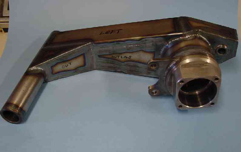
Posted by: TimT Jan 6 2006, 11:36 AM
| QUOTE |
| Also, aren't the cast 911 arms kinda hollow |
This is a 930 trailing arm. we got punted, and the trailing arm broke.
now back to the 914 trailing arm
Attached image(s)
Posted by: jluetjen Jan 6 2006, 12:48 PM
OK, Here are a couple of cases that I've made up as well as the earlier data for reference.
First, Just 1000 lbs -Z, no bulkhead.
232 1.027E-05 -4.044E-05 -1.355E-03 -3.071E-04 6.046E-05 2.470E-06
Now, same model, but with all 3 forces inflicted upon it.
232 -1.035E-03 -1.537E-02 1.325E-03 3.710E-04 -6.441E-05 1.560E-03
Now the model with the bulkhead and all 3 forces.
232 -1.034E-03 -1.534E-02 1.310E-03 3.533E-04 -6.467E-05 1.560E-03
First New Case:
A single gusset of the same 2mm material down the short side per the attached drawing. (Note that the key node is now node 242 after the nodes were renumbered) It appears that twist was reduced in Y and increased in X as a result of this change.
242 -1.148E-03 -1.394E-02 1.323E-03 3.504E-04 -6.904E-05 1.408E-03
I doubt that we can put a gusset on the other side without interfereing with the wheel or tire.
http://www.914world.com/bbs2/uploads/post-2-1136573286.jpg
Attached image(s)
Posted by: jluetjen Jan 6 2006, 02:24 PM
OK. Now I've modified the model to include a full width bulkhead down the inside between the 2 red lines. It's better then having a bulkhead across the piece, but not as good as an external gussset. Here's the numbers...
First, Just 1000 lbs -Z, no bulkhead.
232 1.027E-05 -4.044E-05 -1.355E-03 -3.071E-04 6.046E-05 2.470E-06
Now, same model, but with all 3 forces inflicted upon it.
232 -1.035E-03 -1.537E-02 1.325E-03 3.710E-04 -6.441E-05 1.560E-03
Now the model with the bulkhead and all 3 forces.
232 -1.034E-03 -1.534E-02 1.310E-03 3.533E-04 -6.467E-05 1.560E-03
First New Case:
A single gusset of the same 2mm material down the short side per the attached drawing. (Note that the key node is now node 242 after the nodes were renumbered) It appears that twist was reduced in Y and increased in X as a result of this change.
242 -1.148E-03 -1.394E-02 1.323E-03 3.504E-04 -6.904E-05 1.408E-03
Now with the longitudinal internal bulkhead (actually a "floor" since it's horizontal) of 2 mm materia. (The key node is 232 again).
232 -1.070E-03 -1.421E-02 1.317E-03 3.449E-04 -6.727E-05 1.541E-03
BTW - Keep an eye on the colors. According to this simulation there are some areas up close to the smaller tubes where axial stress on the material is in the neighborhood of 10,000 lb/sq inch.
http://www.914world.com/bbs2/uploads/post-2-1136579064.jpg
Attached image(s)
Posted by: Porcharu Jan 6 2006, 02:50 PM
Another idea for reducing "pucker factor" If we know where the "pucker" or dimple is occuring would a small tube or 2 (or a bolt) welded across the area work as well as the bulkhead (or almost as well.) This would be a very easy way to go if it works - I'm a little nervous about cutting my trailing arms in half and welding them back together. Drilling a few holes and welding in some tubes would be a snap.
Steve
Posted by: McMark Jan 6 2006, 03:19 PM
Steve, those were my thoughts awhile back. Drill a few holes through the entire arm at strategic points and weld in rod. Also thought the same thing for longitudinals.
Posted by: jluetjen Jan 6 2006, 03:21 PM
Steve;
I suspect that what would would happen is that if you could know where a "pucker" were to occur -- and buttressed up that area -- that the stress would then move to another unreinforced area and pucker that area even more. It's kind of the "fat lady in the girdle" sort of excercise. All of that force needs to be transmitted through the trailing arm. If you restrain it in one area, it will pop out in another.
Posted by: Racer Chris Jan 7 2006, 08:04 AM
A point approximating the center of the wheel bearing would be the best the position to apply the forces.
Since the location of point 232 is so close to the longitudinal axis of the trailing arm, when you apply a Y axis load the torguing force (ft-lbs) is much lower than the actual force (lbs) applied. More of the load ends up being applied to the rear support point compared to a real trailing arm.
The current model works well for Z axis loads much but it does decrease both X and Y moments significantly.
Speaking of X axis forces, I think they would be much smaller than half a ton, even braking in a straight line. You could argue that since the moment is smaller the effect is similar but you also pointed out some pretty high force concentrations in one example, on the order of magnitude (1E+05) of the yield strength (4E+05) of the metal. It seems that a little more accurate model is still needed to see if there is any more likelihood of component failure.
In order to more accurately model the location of force application you could simply attach a cone to the surface and use the point of the cone instead of the current point 232.
Posted by: jluetjen Jan 7 2006, 08:55 AM
Good morning Chris. Good thoughts. Give me a minute to upload the stuff that I just finished and then we can run a couple more simulations with the modified force vectors.
Posted by: jluetjen Jan 7 2006, 08:59 AM
OK. Here's a spreadsheet with the different cases that we ran and then some new ones. The big changes is that I've extended the hub out by 2 inches as Chris just described. The forces are still being applied to the center of that "hub". I then ran a model adding a strut as Mugs914 showed in his pictures, and then another test with the external gusset on the short side of the arm. It looks like the gusset provides the biggest improvement in the Y-displacement. I'll upload the overhead view of each simulation in a minute.
Attached image(s)
Posted by: jluetjen Jan 7 2006, 09:01 AM
Base model with the cantelivered hub.
http://www.914world.com/bbs2/uploads/post-2-1136646079.jpg
Attached image(s)
Posted by: jluetjen Jan 7 2006, 09:05 AM
With Mugs914's strut
http://www.914world.com/bbs2/uploads/post-2-1136646322.jpg
Attached image(s)
Posted by: jluetjen Jan 7 2006, 09:06 AM
And now the external gusset
http://www.914world.com/bbs2/uploads/post-2-1136646379.jpg
Attached image(s)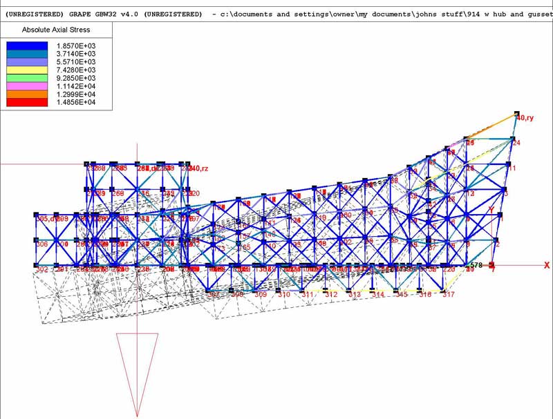
Posted by: jluetjen Jan 7 2006, 09:11 AM
Chris; If I were to assume that your 914 corners at about 1.5 g's (round figure), what sort of braking forces should I use? We can then do some quick vector addition to come up with some more precise force levels. I think that the models that we've done so far are certainly relevent to try out the different strategies for reducing the Y displacement (aka: Toe). Then we can optimise a strategy to ensure that the stresses are kept to manageable levels.
I'll check back in a few minutes.
BTW, how fabricatable would it be to use one piece of metal as both the longitudinal "floor" and the external gusset. Say -- cut a line on both sides of the arm, insert the flat piece of metal and weld from both sides? 
Posted by: Eric_Shea Jan 7 2006, 12:30 PM
John,
Is the rear caliper inner adjuster tube factored into your model?
Posted by: jluetjen Jan 7 2006, 01:27 PM
| QUOTE (Eric_Shea @ Jan 7 2006, 10:30 AM) |
| John, Is the rear caliper inner adjuster tube factored into your model? |
I checked it by adding a 1.125"x12 tube there and it didn't make any difference. The numbers were exactly the same for at least 5 digits.
Posted by: Racer Chris Jan 8 2006, 07:10 AM
John,
I was away all day working on Tangerine 356 Conversion header issues.
I just noticed where you identify your x,y,z axes. I intuitively had chosen the z to be the (real world) horizontal - lateral axis and the y axis to be the vertical, as opposed to choosing the coordinates while looking "down" on the trailing arm. I have to be more careful I guess. 
Posted by: Racer Chris Jan 8 2006, 07:38 AM
I just identified a big difference betweeen a real trailing arm and the GRAPE model. The box tube is actually perpendicular to the pivot axis. This affects the position of the node where you are applying forces relative to the restrained points at the front, therefore alters the moment arm length for x axis rotations. If I'm not mistaken x axis rotation (in the model coordinate system) is what I've been measuring with my tests.
Have you tested my bulkhead using the new point 284? I would still like to place some focus on x axis rotations as something to reduce. Also, what are the units for this column?
Posted by: jluetjen Jan 8 2006, 10:54 AM
| QUOTE |
| I just identified a big difference betweeen a real trailing arm and the GRAPE model. The box tube is actually perpendicular to the pivot axis. |
Actually, on the piece that I have, the small tube is about 7+/- degree from perpindicular with the weld seam up the trailing arm, and the large tube is an additional 7+/- degrees from perpindicular in the opposite direction. This places the hub (I'm guessing) at about 15 degree from the axis of the smaller tube. Why do I say 15 degrees instead of 14? Because on the 911, the pivot axis for the rear semi-trailing arm assembly (from the spring plate's pivot through the trailing arm pivot) is also around 15 degrees. I wouldn't be surprised if Porsche designed the 914 rear end to use similar suspension geometry as the 911, although the way that they got there mechanically would be different. Anyhow, I digress...
| QUOTE |
| This affects the position of the node where you are applying forces relative to the restrained points at the front, therefore alters the moment arm length for x axis rotations. |
Yes -- and not really. Yes it does. That is one of the compromises I made in my model. I wasn't about to spend the time to calculate all of the coordinates 7 degrees off of square with the origin coordinates. And then do the hub an additional 7 degrees off of that. That's the kind of stuff that gave me brain cramp at the start
and why it took me almost a month from when I borrowed the arm until I actually started. I just decided to simplify things and assume that everything was square to start. Once I got the basic model done, I then went back and moved the small tube about 7 degrees from the main arm. Right now the large tube with the hub is perpindicular with the main arm. ( Hmmmm, as I'm writing this it just dawned on me how I could shift the hub assembly by about 7 degrees without a huge amount of recalculation. All it will take is the time to reconstruct the web.)But I don't think it makes a huge difference from what I've seen running the models for a couple of reasons.
1) We've got 3 vectors of force on the model which sum up to a force which is 45 degrees back (away from the small tube) and 45 degrees up. Now shift that about 15 degrees. Basically we could get the same result as moving the total force 15 degrees by increasing the force in the -Y direction, and reducing the force by a corresponding amount in the -X direction. Either way, it's not going to be a magnitude change (Moving the decimal point essentially) as we're seing between the Y and the Z distortion. That is a function of the shape of the structure.
2) One of the features of the software is that I can make an animation of the structure under load. What I can print is only the total displacement (the dotted lines). If you watch it move, you'll see that it's basically bending in a fairly even arc. Shifting the forces by a few degrees just isn't going to change that by much.
| QUOTE |
| If I'm not mistaken x axis rotation (in the model coordinate system) is what I've been measuring with my tests. |
Yes, or more specifically the Z displacement. This is what I have highlighted in the first two rows of the spreadsheet. But after running the model, one of the things that jumped out at me pretty early is that given that the pivot axis at the front, and the coil-over attachment at the tail of the arm (constraining it in the Z direction), the arm is not really twisting that much at all. But after I put the lateral and (cantelivered) -X force vectors on it, that the arm displaced a whole lot in the Y direction -- about 10X the Z displacement. You can see this on the spreadsheet. This is why I standardized on posting the pictures from the top view. If you make yourself a test fixture where you put the arm's pivot axis vertical, and you restrain it perpindicular to that so that it doesn't pivot, then apply the same force on it that you have previously in a twisting fashion. I suspect that you will find that the arm deflects about 10X what you saw on your first experiments. The model suggests (by an order of 10X) that this is where your oversteer is coming from.
| QUOTE |
| Have you tested my bulkhead using the new point 284? I would still like to place some focus on x axis rotations as something to reduce. |
I'm going to be out all afternoon, I'll try to do this (as well as combine the external gusset with an internal "floor" ) some time this week. Unfortunately, with this software, adding features inside of a model is a real test of visual accuity.
| QUOTE |
| Also, what are the units for this column? |
The units of the spreadsheet data should be inches which is the standard units I used for the model. I had to do some off-line calculations to estimate the geometric properties of a 1-inch square by 2 mm's thick. The properties of steel are stored on a second table which I just used as is. If you (or anyone else) is interested, this is what I calculated the geometric properties to be. If someone knows this better then me -- Please speak up now!!!

[B]Geometry for a 1 inch square by 2 mm strip [B]
X-Area: .078792
J-Inertia: .000112
YY-Inertia: 4.1E-5
ZZ-Inertia: .006565
Y-Recovery: .5
Z-Recovery: .5
T-Recovery: .5
Posted by: Eric_Shea Jan 8 2006, 10:58 AM
Can someone resize John's pics to 800pxls W?
Posted by: jluetjen Jan 8 2006, 11:00 AM
I would if I could -- but I can't.
Posted by: Eric_Shea Jan 8 2006, 11:07 AM
No problemo... I 'think' someone here can.
It would just be easier to read and look at all the points if they were 800. That seems to be the perfect size for a 1024 view.
Posted by: Racer Chris Jan 8 2006, 12:35 PM
Chris; If I were to assume that your 914 corners at about 1.5 g's (round figure), what sort of braking forces should I use? We can then do some quick vector addition to come up with some more precise force levels.
I would also use 1.5g for the max limit of braking force. Most of the braking is done by the front tires, so I would estimate one rear wheel at (2000*1.5/2*0.25) 375lb max x axis force. I doubt this would ever occur simultaneously with max y or z forces.
I think that the models that we've done so far are certainly relevent to try out the different strategies for reducing the Y displacement (aka: Toe). Then we can optimise a strategy to ensure that the stresses are kept to manageable levels.

BTW, how fabricatable would it be to use one piece of metal as both the longitudinal "floor" and the external gusset. Say -- cut a line on both sides of the arm, insert the flat piece of metal and weld from both sides?
This places the hub (I'm guessing) at about 15 degree from the axis of the smaller tube.
If you make yourself a test fixture where you put the arm's pivot axis vertical, and you restrain it perpindicular to that so that it doesn't pivot, then apply the same force on it that you have previously in a twisting fashion. I suspect that you will find that the arm deflects about 10X what you saw on your first experiments.
The units of the spreadsheet data should be inches which is the standard units I used for the model
Posted by: jluetjen Jan 8 2006, 07:52 PM
| QUOTE |
| I was curious about the units of the rotational columns. They can be in degrees or radians but not inches. |
Rotations are in radians.
| QUOTE |
| I would also use 1.5g for the max limit of braking force. Most of the braking is done by the front tires, so I would estimate one rear wheel at (2000*1.5/2*0.25) 375lb max x axis force. I doubt this would ever occur simultaneously with max y or z forces. |
Can you give me an estimated CG height for a 914? If in doubt, it's usually pretty close to the crankshaft height. The other thing is the approximate roll-center heights -- front and rear. With that information I've got another software program where I can run it through and come up with a pretty good estimate. On the other hand if you have some data that supports that estimate, that's fine too. You're estimate sounds a little low given that your car is a rear-mid-engined car -- and a fairly low one at that.
For the sake of simplicity, let's just assume that each wheel is braking a quarter of the car's mass, so we're talking about 2000 * 1.5/4 = 750. By the same token, we're talking about a quarter of the car's lateral force at the same G level, so 750 lbs lateraly.
If I remember (or rather can read) my trig correctly, 750 lbs in one direction plus 750 lbs in a perpendicular direction will equal (excel calculation.... COS(RADIANS(45 (degrees)))*750 = 530.33 lbs. Right? So this is what I should use for our force vectors. Now we just need to estimate the forces in roll.BTW, Apparently Grape's calculations tend to overestimate the displacement by about 20% (most likely as a margining factor). This is based on a model done of an actual FF frame compared to experimental measurements taken off of the real frame.
Posted by: Brett W Jan 8 2006, 08:44 PM
Figure the center of gravity is about 16in off the deck.
Posted by: pek771 Jan 8 2006, 08:50 PM
Cool, and very geeky.
Is the "Z" axis the real world vertical plane in the FEA plots, with "X" being the longitudinal (fore and aft)?
I think vectorially, 750# with a 750# perpendicular would yield a (750 x 1.414)pound resultant, not a 530#...
Since I just cut up some suspension consoles yesterday, I recall remarking to myself of how flexy they are. So, Chris' test stand is great for testing the torsional resistance of the trailing arm, but when we look at suspension dynamics and ensuing commentary on the steering and handling characteristics of the car, one should take into account the inherent flex of the chassis mount points. That is a relatively long moment arm to the two chassis mount points from the main box section.
Pat
Posted by: brant Jan 8 2006, 10:01 PM
| QUOTE (pek771 @ Jan 8 2006, 07:50 PM) |
| Cool, and very geeky. Is the "Z" axis the real world vertical plane in the FEA plots, with "X" being the longitudinal (fore and aft)? I think vectorially, 750# with a 750# perpendicular would yield a (750 x 1.414)pound resultant, not a 530#... Since I just cut up some suspension consoles yesterday, I recall remarking to myself of how flexy they are. So, Chris' test stand is great for testing the torsional resistance of the trailing arm, but when we look at suspension dynamics and ensuing commentary on the steering and handling characteristics of the car, one should take into account the inherent flex of the chassis mount points. That is a relatively long moment arm to the two chassis mount points from the main box section. Pat |
Pat,
most of the race cars have bracing on the suspension consoles and no longer have this flex issue.
brant
Posted by: pek771 Jan 8 2006, 10:23 PM
Thanks Brant:
I'm trying to absorb this, keeping in mind I have to put my rustbucket back together, and am looking to stiffen this area up while I have it apart. From some of the photos of the race cars, there seems to be a wide variation of rear suspension designs. I suspected most racers have this area stiffened. Intuitively, I would think the biggest load is on the inner console ear area.
Regardless of the torsional characteristics of the trailing arm, any load is ultimately transferred into the longitudinal members and appendage braces. So, would this bracing be as strong a platform as Chris test rig?
Very interesting topic.
Pat
Posted by: Racer Chris Jan 9 2006, 06:53 AM
For the sake of simplicity, let's just assume that each wheel is braking a quarter of the car's mass,
If that were the case then brake pad wear would be equal front and rear. Pad wear is around 3-1 favoring the front.
By the same token, we're talking about a quarter of the car's lateral force at the same G level, so 750 lbs lateraly
Posted by: Racer Chris Jan 9 2006, 07:00 AM
Regardless of the torsional characteristics of the trailing arm, any load is ultimately transferred into the longitudinal members and appendage braces. So, would this bracing be as strong a platform as Chris test rig?
Posted by: jluetjen Jan 9 2006, 07:18 AM
| QUOTE (pek771 @ Jan 8 2006, 06:50 PM) |
| I think vectorially, 750# with a 750# perpendicular would yield a (750 x 1.414)pound resultant, not a 530#... |
Pat;
Actually I wasn't quite accurate when I said that it's straight vector addition. We're dealing with a traction circle. If the car generates a maximum of 1.5 G's under pure braking, and 1.5 G's under pure lateral, then when you combine the two you will wind up with a situation where the braking force in X + lateral force in Y = 1.5G's in total (in a 45 degree direction 1/2 of the way between X and Y). So it's really a case of what number is X = 1.5G's at a 45 degree angle.
Posted by: jluetjen Jan 9 2006, 08:46 AM
| QUOTE (Racer Chris @ Jan 9 2006, 04:53 AM) | ||
If that were the case then brake pad wear would be equal front and rear. Pad wear is around 3-1 favoring the front. |
I'm not arguing with the brake wear that you're seeing, but that sounds like an awfully strong front bias for a mid-engine'd car with a fairly low CG like a 914. Of course there are other factors that affect this like ventelation, driver preference, shocks, springing and the whole gammut. But at first blush it doesn't sound like you're getting good use out of your rear brakes. But I digress...
Posted by: Racer Chris Jan 9 2006, 08:49 AM
I can easily adjust my bias to lock up the rears first.
Posted by: jluetjen Jan 9 2006, 10:06 AM
Moving along.... 
Here's pictural output of running the model with the hub and adding a bulkhead about half way down the length of the arm. I have not changed the force vectors yet in order to keep a consistent comparison between the different strategies that we're discussing. I'll post the data after I also run a separate model with a gusset and a floor combined. BTW, I've also updated the spreadsheet to translate the radians into degrees.
Attached thumbnail(s)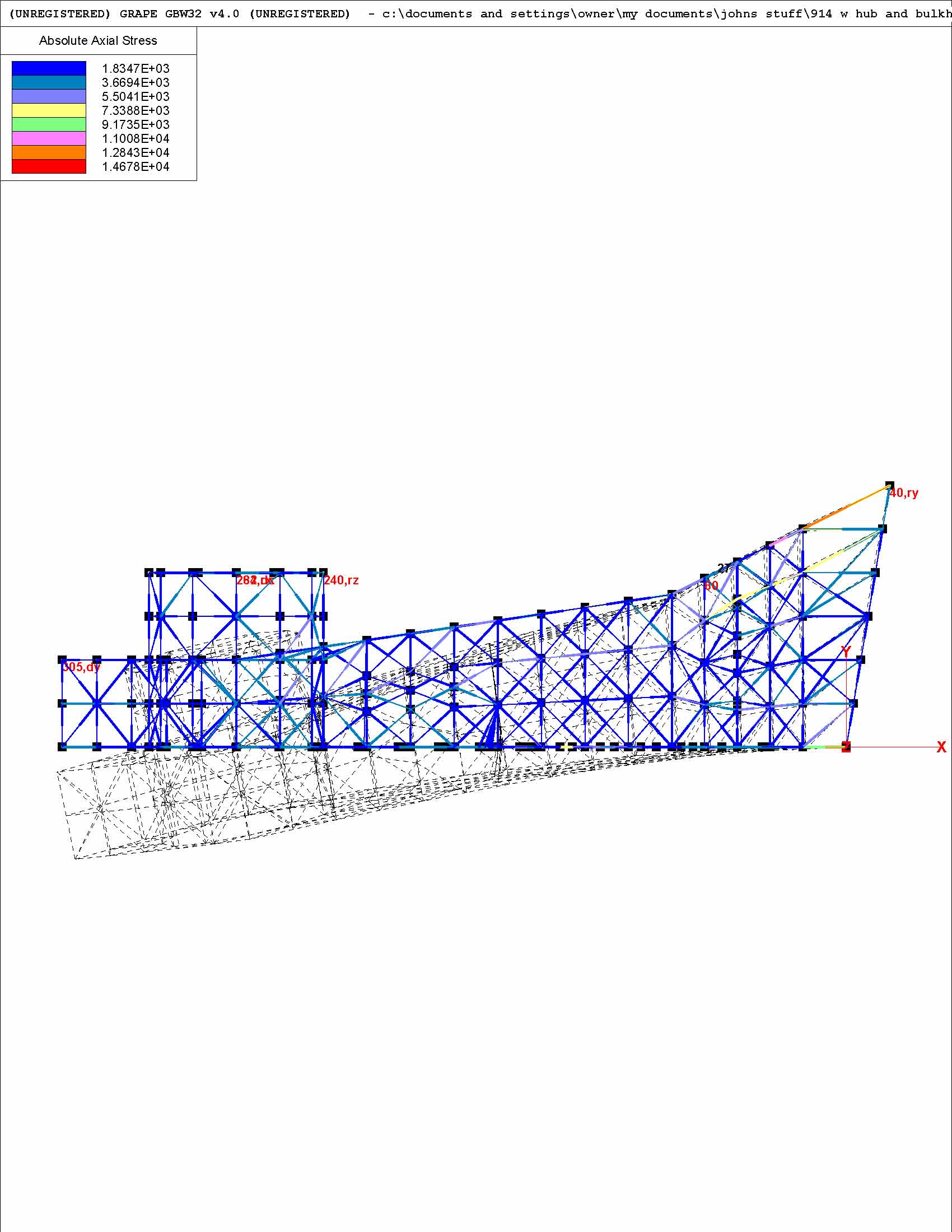
Posted by: jluetjen Jan 9 2006, 12:06 PM
Here's the spreadsheet with the result of running the model with Chris's bulkhead included, and then with a floor (horizontal bulkhead) and external gusset both added. This last version seems to be the stiffest, but as a result increases the forces at the outer end of where the trailing arm attaches to the smaller tube -- where Chris has already attached some additional gussets. I'll explain the "short" and "long" gussets in the next reply.
Attached thumbnail(s)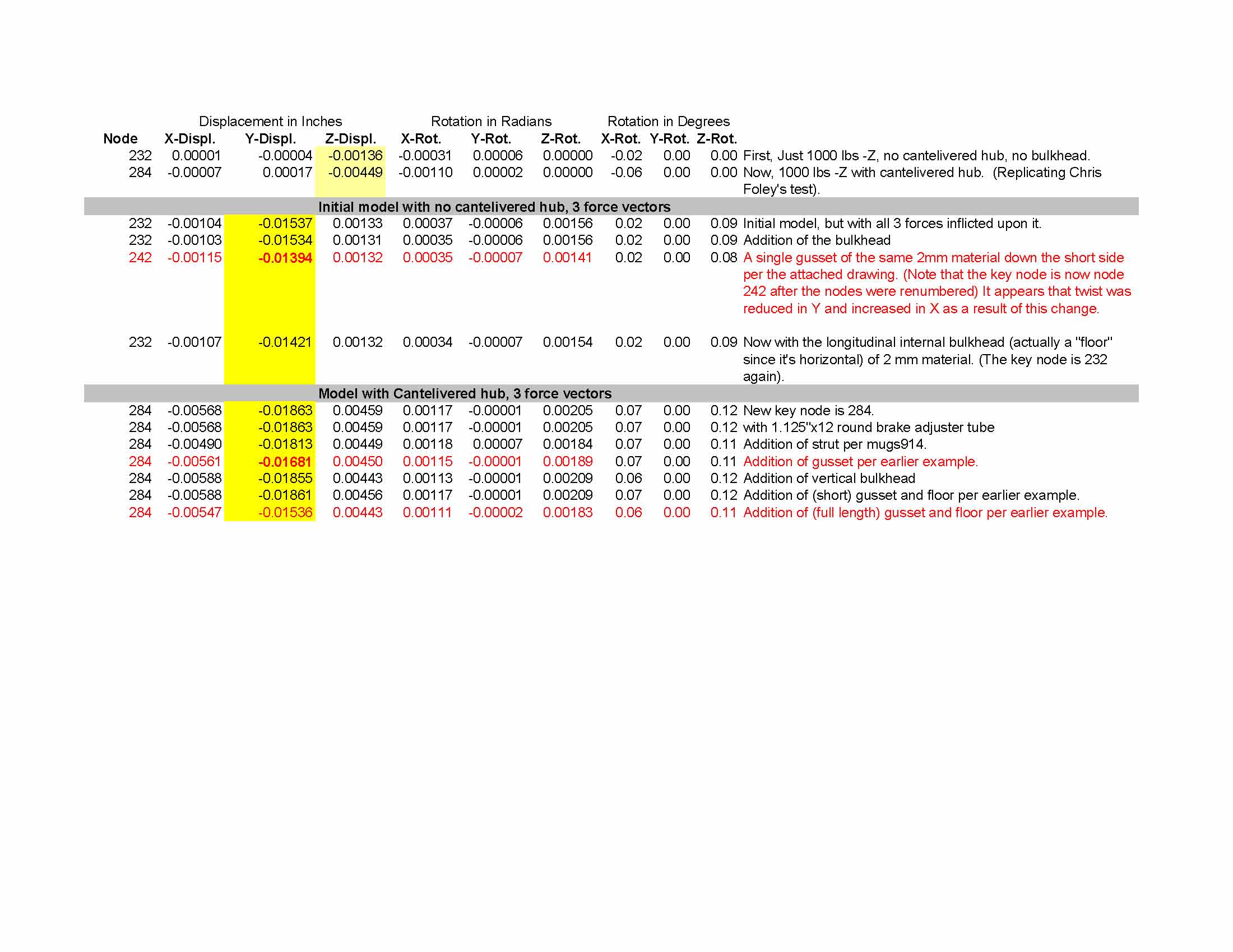
Posted by: jluetjen Jan 9 2006, 12:22 PM
Here's the distortion top view and stresses for the model with an additional gusset as well as a "floor" which is essentially the gusset continued through to the other side of the arm. When I first made this update, I didn't include the portion next to the red line and was surprised to find that the results were marginally worse then the earlier example I had run with a gusset. Comparing the two models I noticed that I had stopped the gusset short of the full length. This is the "Short" gussetted model. When I added the gussetting next to the red line, the performance improved significantly -- and back to what I was expecting. I guess it just goes so show how sensitive some "small" changes in can be in relation to the model.
Attached thumbnail(s)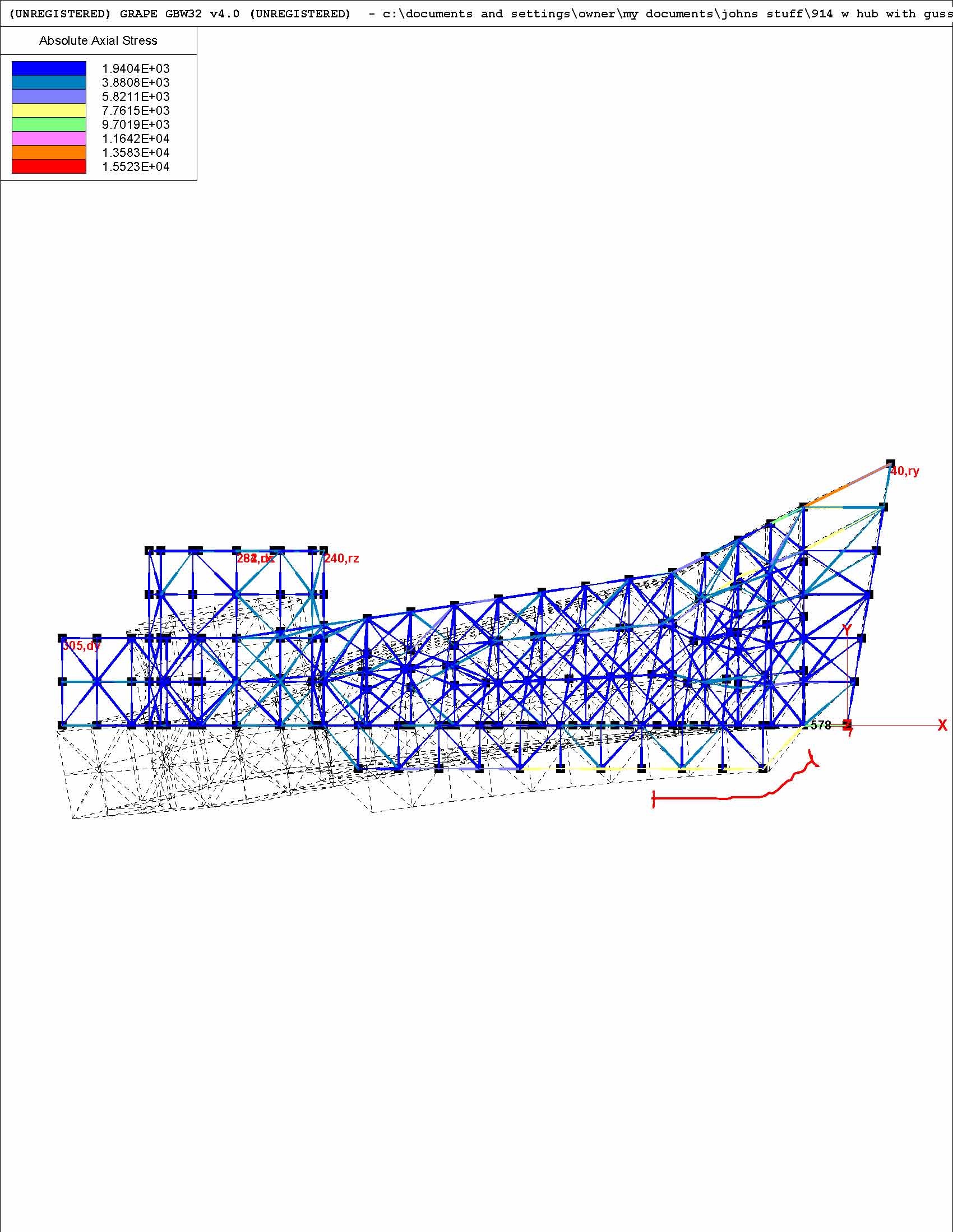
Posted by: jluetjen Jan 9 2006, 12:41 PM
Here's a view of the same model from outside of the arm, so picture the hub is pointing towards your left shoulder. Note that the forces are now being channelled down the lower outside edge of the trailing arm, in addition to along the length of the gusset on the backside (in this picture).
Posted by: jluetjen Jan 9 2006, 12:44 PM
Oops! Here's the attachment.
Attached thumbnail(s)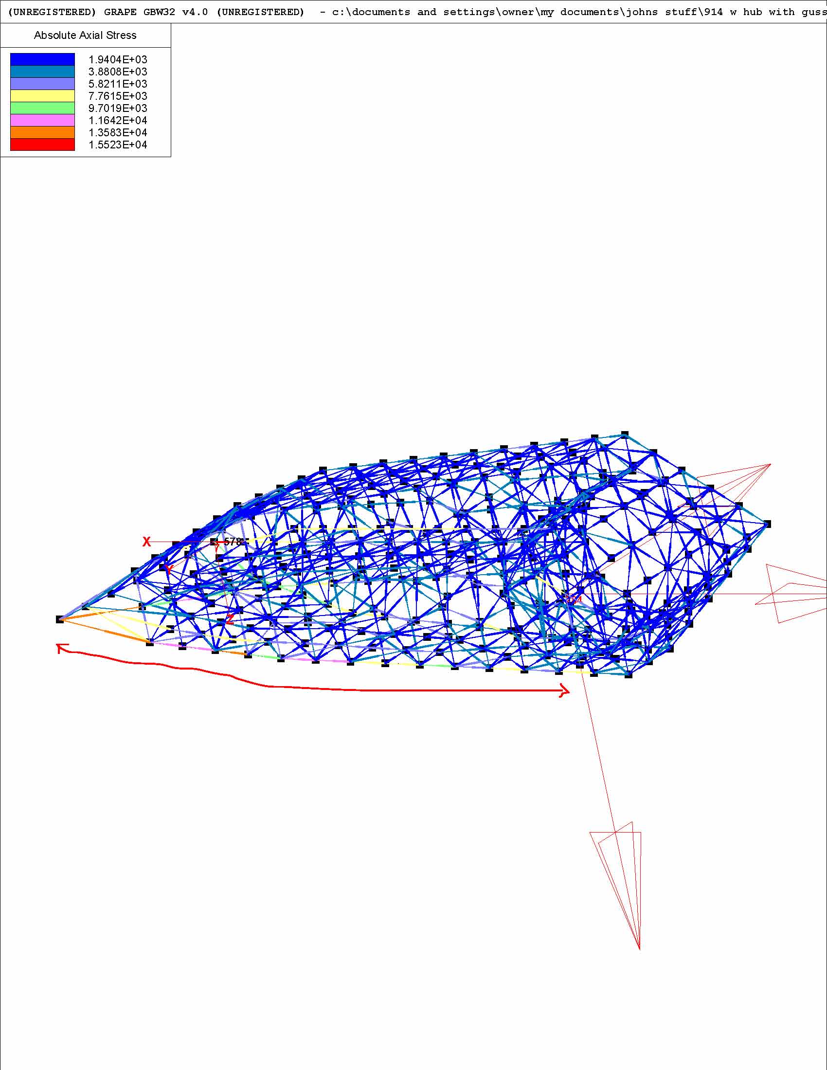
Posted by: Howard R Jan 10 2006, 08:05 PM
So after all of this clever stuff, is there a conclusion as to the best and lightest way to reinforce trailing arms? I have them sitting on the floor of my shed ready to start cutting and welding.
Posted by: ChicagoChris Jan 10 2006, 09:07 PM
I agree. I love watching you guys talk teck but when do you say "yes it works" and "it is lighter".
And if you wouldn't mind...a picture of what you put inside the arm would be handy. I get the bar on the leading edge. and that the outer triangle may have added strength to the corner but nothing measurable to the flex. But I seem to be missing what you put inside.
Posted by: Thorshammer Jan 10 2006, 09:17 PM
Remember young whipper snappers, Measure twice cut once, or
Its done when I say its done.
Or Shut the hell up I am thinking.
All us back yard guys are just amazed at what we are seeingn here. My brain is hurting right now.
Botomline is it what it is until we test it and proclaim it is better. But we really want to know why it is better.
Erik Madsen
Posted by: TimT Jan 10 2006, 09:32 PM
You may have to "see" some things, you wont get blueprints to use. There is enough quality info and R&D here.
Chris knows what he is doing, John the nOOb is a whiz at FEA analysis....
Posted by: brant Jan 10 2006, 10:56 PM
I think people should send core arms to Chris to get the secret, "whats inside"
and I have to be honest here. More important than the stiffening, is the camber.
I'm thinking that the camber (-negative I mean) is the genius break through here!
good job chris!
brant
Posted by: Racer Chris Jan 12 2006, 09:35 PM
Ok. I think I have a better handle on the mathematics of the forces at play here.
For simplicity I reduced the problem to two dimensions.
Imagine a vertical plane, perpendicular to the direction of travel, containing the center point of the hub and the center point of the tire contact patch. Another important point is where the trailing arm axis intersects the plane. The contact patch is 7" outboard and 12" below the axis point. Two simultaneous forces occur during cornering, weight and cornering friction. The forces act on the axis point through the contact patch. At the contact patch the weight may reach about 1000lbs due to weight transfer. The cornering friction may be up to 1.5 times this amount - 1500lbs. Both forces can be split into two components - one pointing directly at the axis and the other perpendicular to the first - creating torque. The force components aiming directly at the axis can be further split into two components - horizontal and vertical - all pointing directly at the axis.
The torque components of both forces have opposite direction so one partially cancels the other, leaving a net torque of 900 ft-lbs. The sum of the two vertical components works out to about 1400lbs. The sum of the two horizontal components works out to about 820 lbs. That's more than I expected for the lateral force.
Posted by: Racer Chris Jan 12 2006, 09:50 PM
The contact patch is 7" outboard and 12" below the axis point.
These numbers are approximately correct for a 9.5" slick on 7" rims. A narrower track width and taller tire will tend to increase the torque and decrease the lateral load, but lower grip will result in all the values being smaller anyway.
Posted by: Racer Chris Jan 13 2006, 08:06 AM
I came up with a simple way to fixture a trailing arm to my bench so I can test them using combined rotational and lateral loads.
Attached image(s)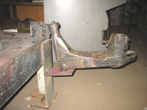
Posted by: jluetjen Jan 13 2006, 08:38 AM
OK Folks. And now the moment that you've been waiting for -- Updated models with the forces moved out to the area of the contact patch. Some conclusions...
1) For the most part all of the displacements (aka: bending) got worse. The only exception was...
2) The model with the external gusset and internal floor. This model's output stayed the same (I double checked it too) and as a result was the best performing. Looking at the data, it even suggests that this model may channel the forces in such a way as to twist around the X-axis positively (increasing camber) by a small amount as opposed to twisting negatively.
3) This stuff is getting pretty computationally demanding. The base model runs almost instantaniously. The model with the bulkhead took about 1 minute, the model with the gusset kept my computer busy for 2 minutes, while the model with the bulkhead and floor took 3:48. Imagine doing that by hand!
Here's the data.
Attached thumbnail(s)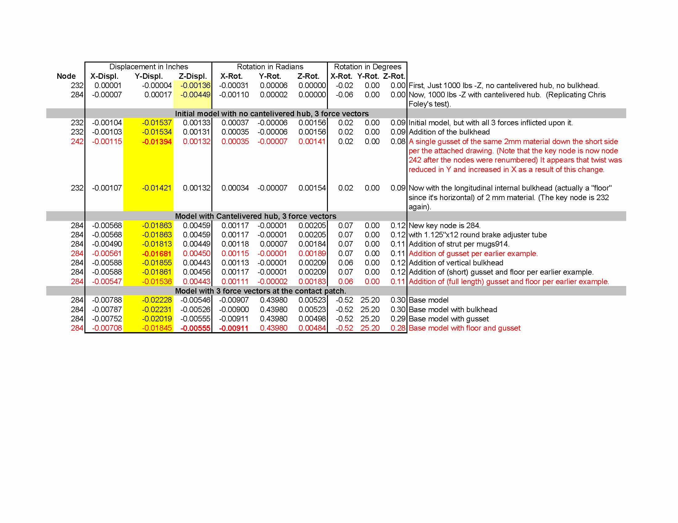
Posted by: jluetjen Jan 13 2006, 08:44 AM
Here's how I set the models up. I used the geometry for a 3x3 inch solid steel beam, straight out from point 284 for 3 inches (a total of 7 inches from the X-axis), and 12 inches down. At that point (node 308 in this model) I applied the same 1000 lb forces as before (in order to remain consistent with the earlier data). So -1000 lbs X, -1000 lbs Y, and 1000 lbs Z.
Attached thumbnail(s)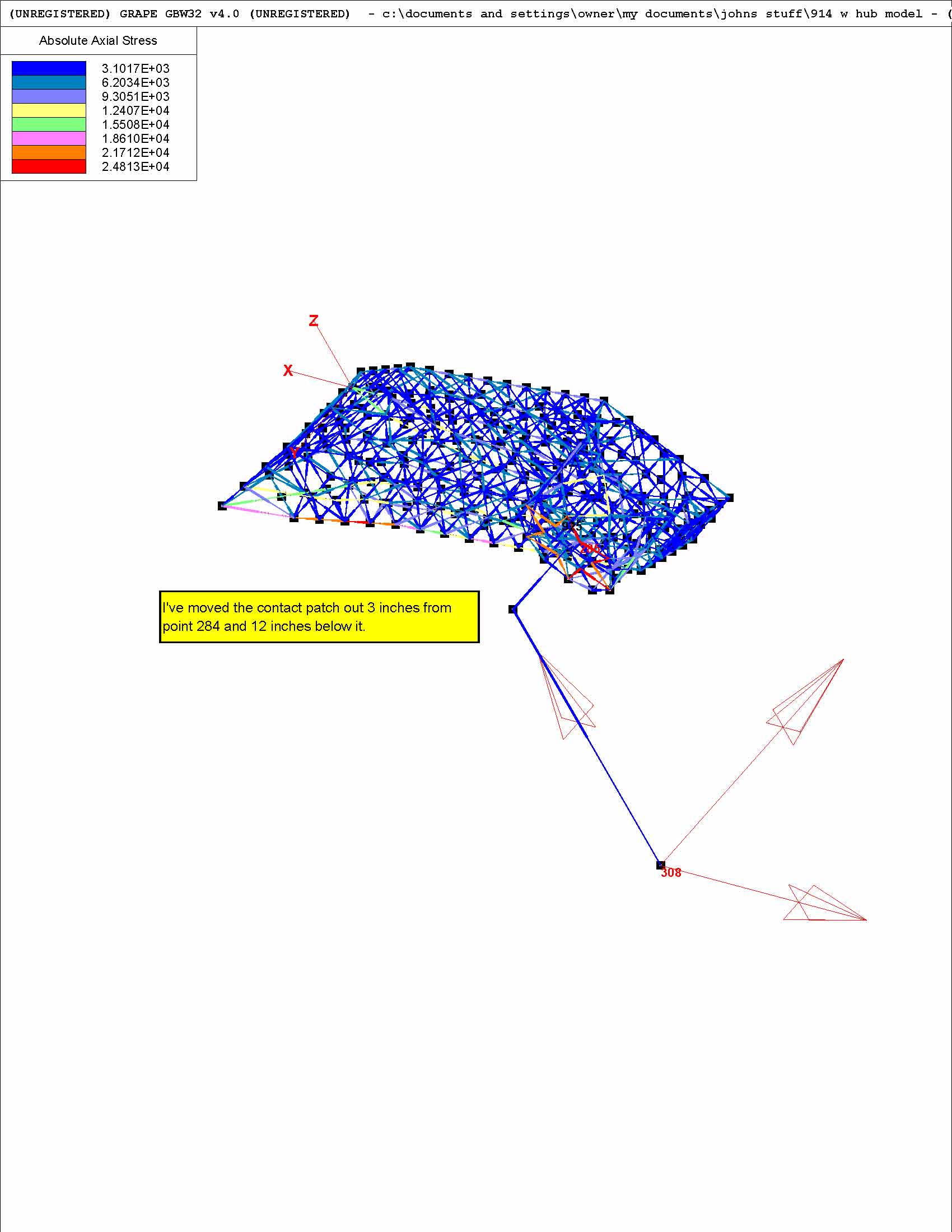
Posted by: jluetjen Jan 13 2006, 08:46 AM
Here's the top view of the base model.
Attached thumbnail(s)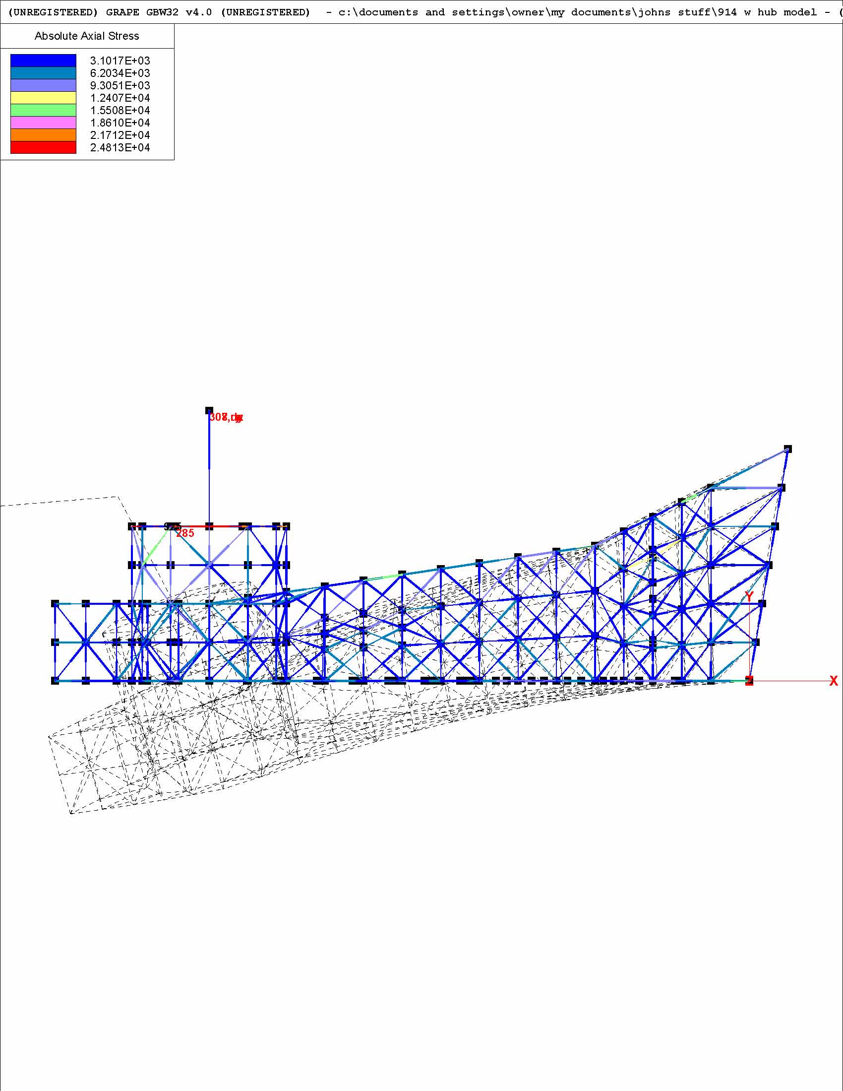
Posted by: jluetjen Jan 13 2006, 08:47 AM
Here's the base model with the vertical bulkhead.
Attached thumbnail(s)
Posted by: jluetjen Jan 13 2006, 08:48 AM
Here's the version with just the external gusset
Attached thumbnail(s)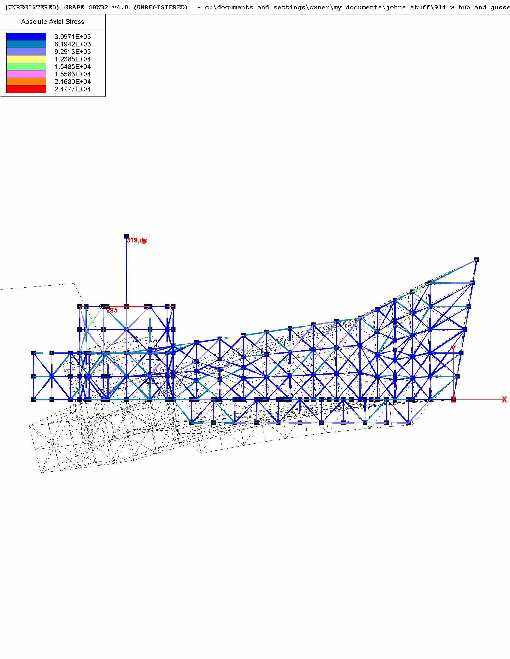
Posted by: jluetjen Jan 13 2006, 08:50 AM
And finally the model with the external gusset and the floor added.
sigh.... 
Attached thumbnail(s)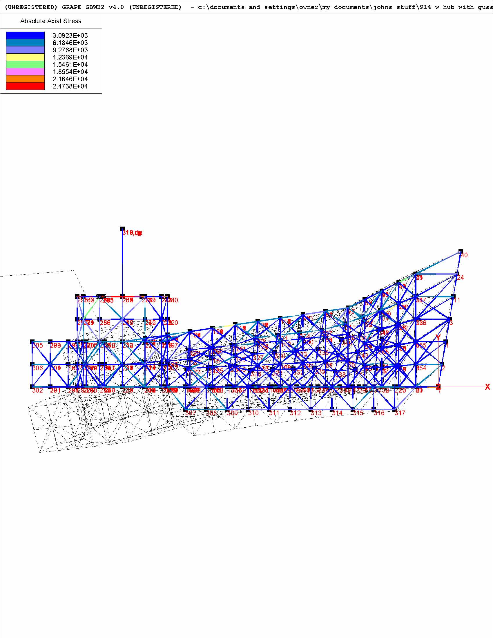
Posted by: jluetjen Jan 13 2006, 08:52 AM
Now it's Chris's turn...
Posted by: Racer Chris Jan 16 2006, 09:17 AM
I'm going to graphically show how I arrived at the force numbers I posted above.
Point A represents a point along the twisting (longitudinal) axis of the trailing arm. Point B represents the center of the tire contact patch. I estimated the center of the tire to be offset 7" outboard of the axis, and 12" below. The distance between the points is 13.8". The ground is pushing up on the tire with a force of about 1000lb. At 1.5G the sideways force exerted on the tire contact patch is about 1500lb.
Attached image(s)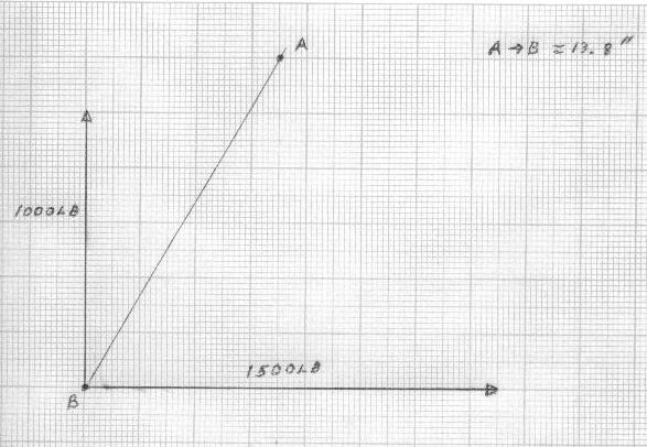
Posted by: Racer Chris Jan 16 2006, 09:20 AM
Working with just the sideways force for a moment, I can separate that into two vector components. One points directly at point A and the other is perpendicular to the line segment A-B.
Attached image(s)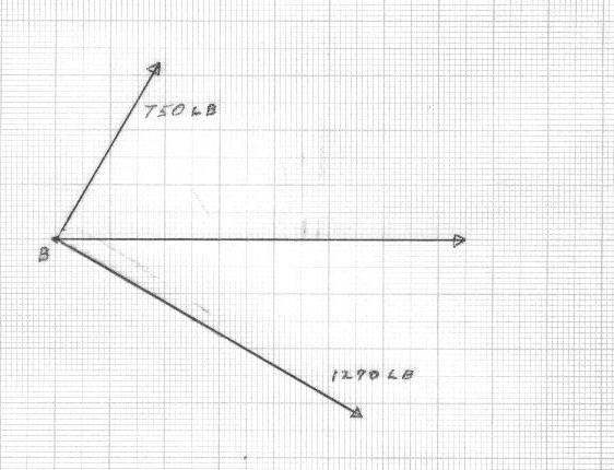
Posted by: Racer Chris Jan 16 2006, 09:22 AM
Doing the same thing for the vertical force yields this graph. Notice the perpendicular component points the opposite direction from the previous graph.
Attached image(s)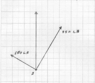
Posted by: Racer Chris Jan 16 2006, 09:24 AM
Now both sets of force vectors are shown simultaneously.
Attached image(s)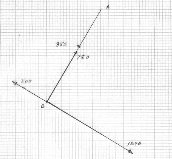
Posted by: Racer Chris Jan 16 2006, 09:26 AM
Performing simple vector addition yields this graph.
A force of 1600 lb is aimed directly at Point A, and a force of 790 lb is perpendicular - twisting the trailing arm.
Attached image(s)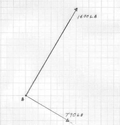
Posted by: Racer Chris Jan 16 2006, 09:28 AM
Working only with the force vector directed at point A I can further split that into a vertical and a horizontal component. Since that force is aimed directly at A I moved the origin to point A.
Attached image(s)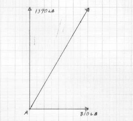
Posted by: Racer Chris Jan 16 2006, 09:34 AM
Since the perpendicular force vector is 13.8" from Point A it exerts a torque of 910 ft-lbs.
Attached image(s)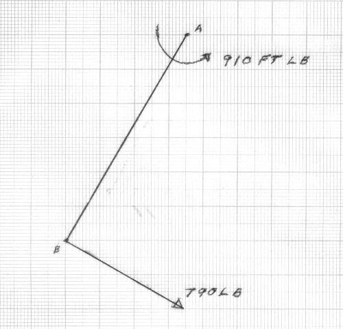
Posted by: Racer Chris Jan 16 2006, 09:38 AM
Now graphing everything simultaneously it can be seen that the two forces acting on the tire contact patch can be studied as three forces acting directly on the trailing arm at a point along the longitudinal twisting axis.
1) a vertical force pushing up on the trailing arm of 1390 lb.
2) a horizontal force of 810 lb trying to bend the trailing arm laterally.
3) a torque of 910 ft-lb trying to twist the trailing arm.
Attached image(s)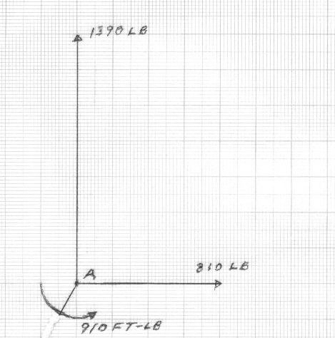
Posted by: Racer Chris Jan 16 2006, 09:39 AM
Any questions? 
Posted by: jluetjen Jan 16 2006, 03:38 PM
Wow -- I started having flashbacks to high-school math!
One question now that you've done all the math....
By just moving the application of the forces out to the contact patch like I did in the last round of models (based on your input -- thank you!) did I do essentially the same thing? In a couple of days I'll try modeling your forces directly on the arm and see if it results in similar outputs to what I go by moving the forces.
(BTW -- I've got no internet until tomorrow some time thanks to a tree that fell over yesterday morning in the high winds. On the way to the ground the tree also snapped off a utility pole at ground level and yanked all of the wires to our house.  )
)
Posted by: Travis Neff Jan 16 2006, 04:35 PM
| QUOTE (Racer Chris @ Jan 16 2006, 07:39 AM) |
| Any questions? |
when do you get started for external customers?
Posted by: Racer Chris Jan 16 2006, 04:40 PM
| QUOTE (jluetjen @ Jan 16 2006, 04:38 PM) |
| By just moving the application of the forces out to the contact patch like I did in the last round of models (based on your input -- thank you!) did I do essentially the same thing? |
You moved the force application point outboard too far. You added 7" from point 284 but it should be 7" from the approximate centerline of the box. Otherwise you did the same thing.
Posted by: Racer Chris Jan 16 2006, 04:44 PM
when do you get started for external customers?
Posted by: Racer Chris Jan 16 2006, 04:49 PM
Wow -- I started having flashbacks to high-school math!
Once I actually sat down and started working on the problem it turned out to be fairly simple. I think, even adding the 3rd dimension wouldn't be too complicated, but a bit tough on a sheet of graph paper.
I've got no internet until tomorrow
I hope you at least have electricity tonight.
Posted by: Brett W Jan 16 2006, 06:41 PM
Can someone please resize the images? 
Posted by: Racer Chris Jan 16 2006, 08:35 PM
| QUOTE (Howard R @ Jan 10 2006, 09:05 PM) |
| So after all of this clever stuff, is there a conclusion as to the best and lightest way to reinforce trailing arms? I have them sitting on the floor of my shed ready to start cutting and welding. |
We're not done quite yet. I'm pretty happy with the results of my 3 piece reinforcement but the tests aren't complete. Hang in there.
Posted by: pek771 Jan 16 2006, 08:53 PM
Chris is pretty close on this. I thought about it while I applied Dry-Lok to the basement walls today.
My crude treatment has a twisting force of 1142 ft-lb, not counting any sway bar, and without constraint from the shock absorber laterally. This is using the 13.8" and 7", with the 1500# side load and 1000" vertical load. I did not use any of the acute angle deviations from the normal axes, as would be encountered in a real trailing arm, but I believe were incorporated in the Chris and John stuff.
If I could upload my scratch paper from the scanner, I'd post it.
Chris and John did a very masterful job on this real world engineering problem, in case anyone had any doubts.
Pat
Posted by: jluetjen Jan 17 2006, 04:58 PM
Comcast came to the house and we're back in business today.
OK. I've gone back and updated my earlier postings with revised outputs reflecting the contact patch being only about 3 inches outside of node 284. The results are similar to the earlier outputs. The big difference is that by reducing the distance out from the center from 11 inches to 7, we actually increased the twisting (torque force) some. Playing with Chris's vector math will show why.
Posted by: Racer Chris Jan 18 2006, 06:56 AM
Thanks John!
Looking at the data -
It appears that the Y displacements are all around 20 thousandths of an inch. The corresponding rotation is 25 degrees? If you measured the angular change of the surface at node 284 (X direction in the X-Z plane) I think it would be quite small.
The Z displacements are all around 5 thousandths with a corresponding rotation of 0.5 degrees. At least that is in the same order of magnitude as the real world experiments. Do these rotations correspond with the angular change (Z direction in the X-Z plane) of the surface at node 284?
The angular change of this surface is what should closely follow my data if the model is believable.
I am surprised (disappointed) that the model doesn't reflect the improvement I see from adding the bulkhead. There must be something going on in the real world that the model doesn't reflect.
It looks like there are some nodes near the outer pickup point that have very high stress levels. This corresponds with the earlier comment about cracks in the pivot tube near this location.
Posted by: jluetjen Jan 18 2006, 07:40 AM
Chris; Good catch about the magnitude of the y-rotation. It's not real clear to me how that manifests itself in the real world short of the hub trying to twist itself off of the arm under braking. As I mentioned, I really haven't modelled the hub that accurately since it should be modeled as a solid piece of metal as opposed to being fabricated sheet metal. This definitely gives me an appreciation for the stress that a hub has to deal with.
Here's a couple of different views of the 3 primary models -- the base model, the model with the vertical bulkhead and the model with the gusset and floor. In this case you are looking down the arm. The X and Z rotation is much clearer in the animation rather then just the distortion plot. Does anyone have any ideas on how to capture the "movie" off of my screen and post it?
First the base model
Attached thumbnail(s)
Posted by: jluetjen Jan 18 2006, 07:45 AM
This is the model with the bulkhead.
Attached thumbnail(s)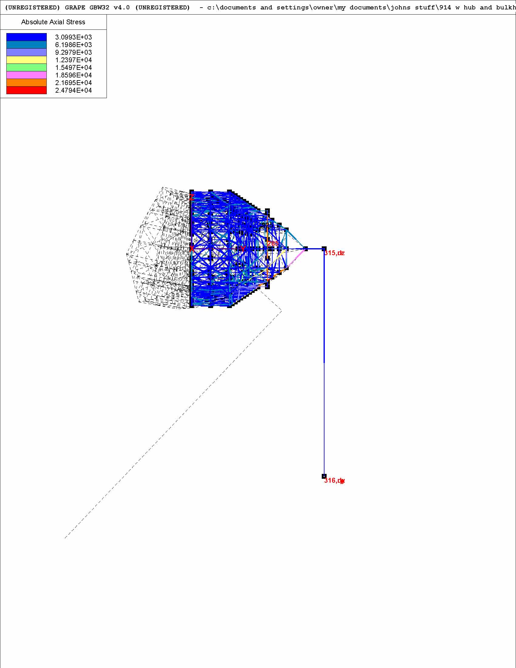
Posted by: jluetjen Jan 18 2006, 07:46 AM
And the model with the gusset and floor.
Attached thumbnail(s)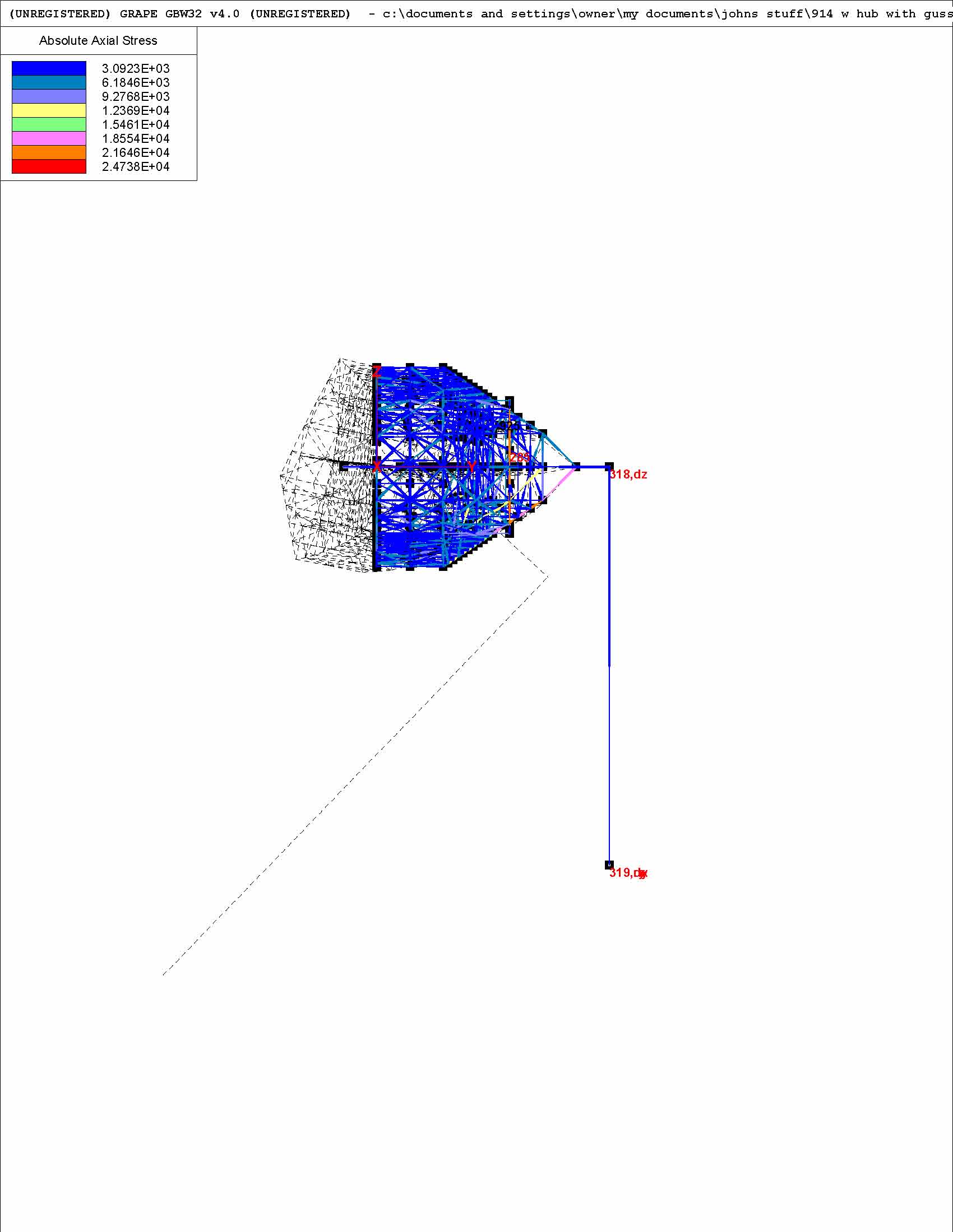
Posted by: jluetjen Jan 18 2006, 07:55 AM
Here's a different view that may be helpful to understand the Y-Rotation issue. Note the very high stresses in a star pattern at the hub. I believe that this is the result of node 284 trying to spin (torque around) and thus add a lot of stress to those elements that make up the web in that area.
Attached thumbnail(s)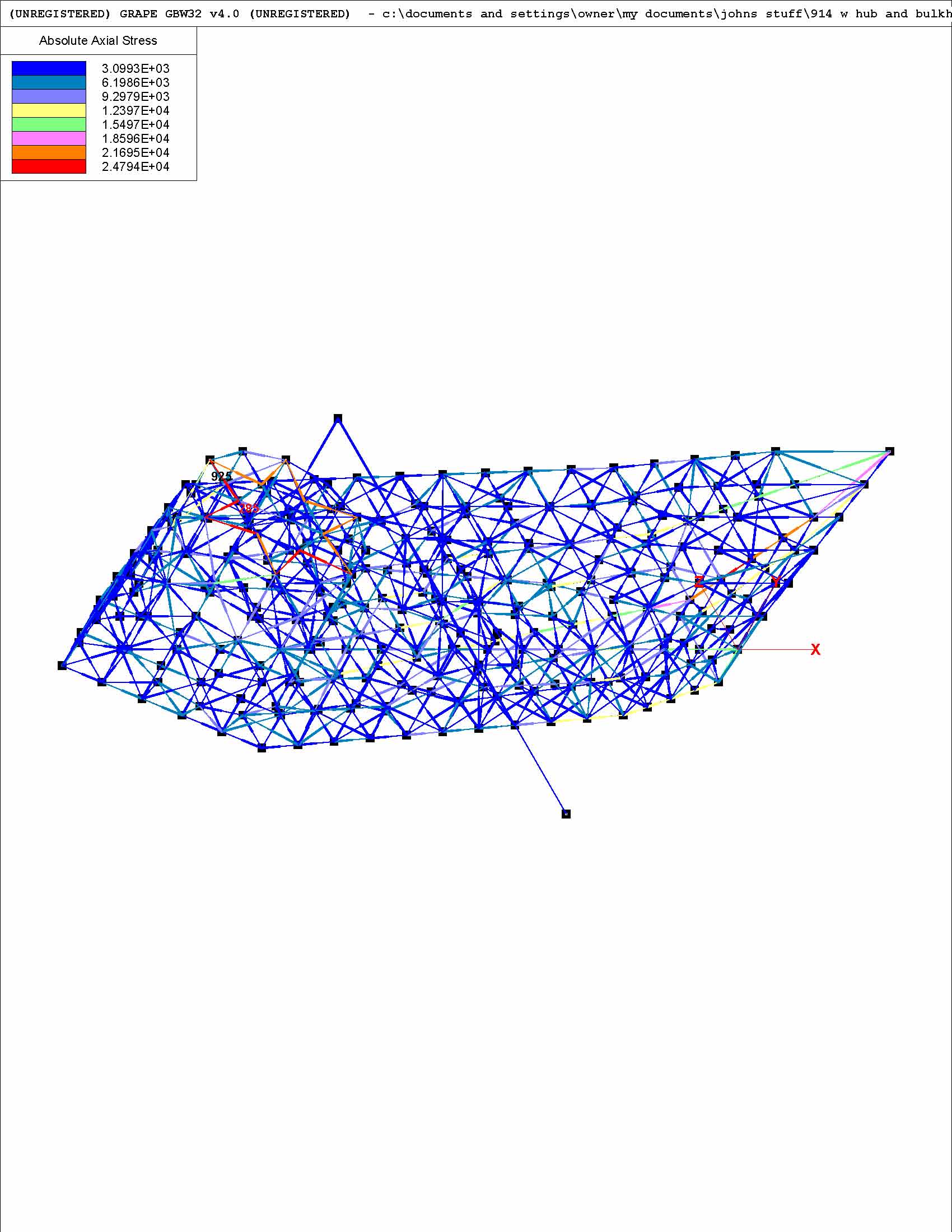
Posted by: Racer Chris Jan 18 2006, 09:30 AM
John,
It is apparent that the "arm" you added to move the forces out to the contact patch also is bending at node 284.
Using the values I computed can you apply the loads directly to node 284, ignoring the braking force. You will have to calculate the appropriate force to equal 900 ft-lbs torque for the vertical (down) load.
Posted by: jluetjen Jan 18 2006, 01:00 PM
Chris;
The software only allows me to add forces in the X, Y and Z direction. There's no place to add torques. Would you agree that as a result I should be adding 1390 lb vertically in addition to (910 * 12 / 7 inches = ) 1560 lbs vertically to equal 2950 lbs vertically? And then the 810 lbs horizontally.
Does this sound right?
Posted by: Racer Chris Jan 18 2006, 05:00 PM
Does this sound right?
Not exactly. The 1390 is in the opposite direction and is not aimed at node 284. I think it could be ignored, since it shouldn't cause any bending or twisting. If included it needs to aim at a point on the twisting axis (imaginary line between the shock absorber mount and somewhere along the pivot shaft) parallel to node 284.
The 910 is foot pounds. If node 284 is only 3 inches from the twisting axis you need to multiply the force by 4 to get the same torque effect.
Posted by: jluetjen Jan 18 2006, 05:11 PM
| QUOTE (Racer Chris @ Jan 18 2006, 03:00 PM) | ||
Not exactly. The 1390 is in the opposite direction and is not aimed at node 284. I think it could be ignored, since it shouldn't cause any bending or twisting. If included it needs to aim at a point on the twisting axis (imaginary line between the shock absorber mount and somewhere along the pivot shaft) parallel to node 284. The 910 is foot pounds. If node 284 is only 3 inches from the twisting axis you need to multiply the force by 4 to get the same torque effect. |
Duh!
I wasn't thinking right. Let me try again. As far as ignoring the twisting forces -- I'm not there. Maybe I'll stick on a cone so that the point is about 12 inches from the axis and then apply the 910 lb-feet there.
Posted by: Racer Chris Jan 18 2006, 06:53 PM
As far as ignoring the twisting forces -- I'm not there.
I'm not suggesting ignoring any twisting forces. The 1390lb vertical up is the component that pushes straight into the trailing arm. It is the part of the "weight" that does not exert ANY twisting force. If you want to include it, break it up and apply it at several nodes on the bottom the trailing arm That would eliminate any point loading.
All the twisting force is included in the 910 ft lb. What's wrong with multiplying the torque by the fraction of a foot node 284 is from the axis? This eliminates any extraneous structure that might deform under the load.
My last graph shows all the forces being applied at what I labeled point A (an imaginary point on the longitudinal axis of the trailing arm). You just need to figure out how far node 284 is from the axis.
The horizontal force can be applied at node 284 since that is in a direct line with the axis, as viewed from the side.
Posted by: Racer Chris Jan 18 2006, 07:12 PM
Maybe this will help.
Imagine that all three arrows I drew are in the same plane as node 284.
The vertical up arrow needs to be a force of 1390lb.
The horizontal arrow needs to be a force of 810lb.
The vertical down arrow needs to be a force of 3600lb!!! That's right. It is only 3 inches from the centerline of the trailing arm box.
Attached image(s)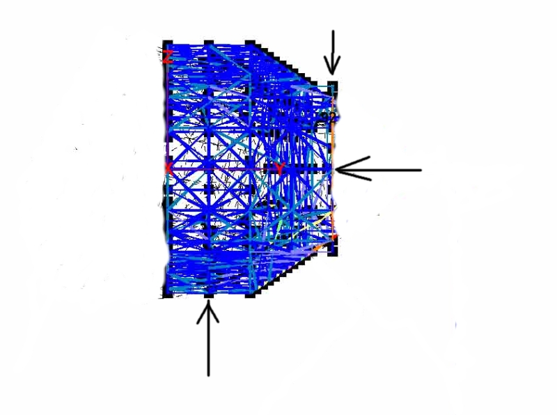
Posted by: jluetjen Jan 19 2006, 07:43 AM
OK. Here you go -- although I fear that we might be going down a "rat hole" with this approach. The reason is that I fear that we're trying to kluge the computations which are already inherent in the model. At the end of the day I don't believe that it really tells us any more, but could very well confuse us more. Kind of like if you wear one watch -- you're always pretty sure what time it is, but if you wear two watches you'll never know what time it is. In this case we'll get another set of numbers, but since they ignore braking and other lateral forces -- of course they'll be different.
The picture below is looking at the arm from behind the shock mount and is a little busier then normal to show what was done.
Forces: Per Chris's diagram above.
Constraints: Both front pivots are constrained in all three directions -- X, Y and Z. So those points won't move. I had to constrain the shock mount in the vertical (Z) direction to keep the model from flying all over the place. I'm kind of concerned about his since this constraint is only a couple of inches away from where we're applying the vertical forces. Essentially I'm concerned that I'm over constraining the model.
Results: The model is still bending along it's length. While I follow Chris's vector math, I don't believe the way that the forces are being applied to the arm accurately reflect the environment the arm is in. For example, the arm never sees a positive Z force at the bottom of the arm -- but our model has such a force. So we're essentially solving a problem that doesn't exist from a mathematical perspective.
I think a better way to cross check the model and help develop a test methodology would be to do the vector math as of point 284. Basically do the math so that the answer results in a single torque being applied at point 284. This answer can then be used to mount a beam at a given angle from X/Y/Z which Chris can then fabricate and test with. I'll try giving it a shot later today.
Attached thumbnail(s)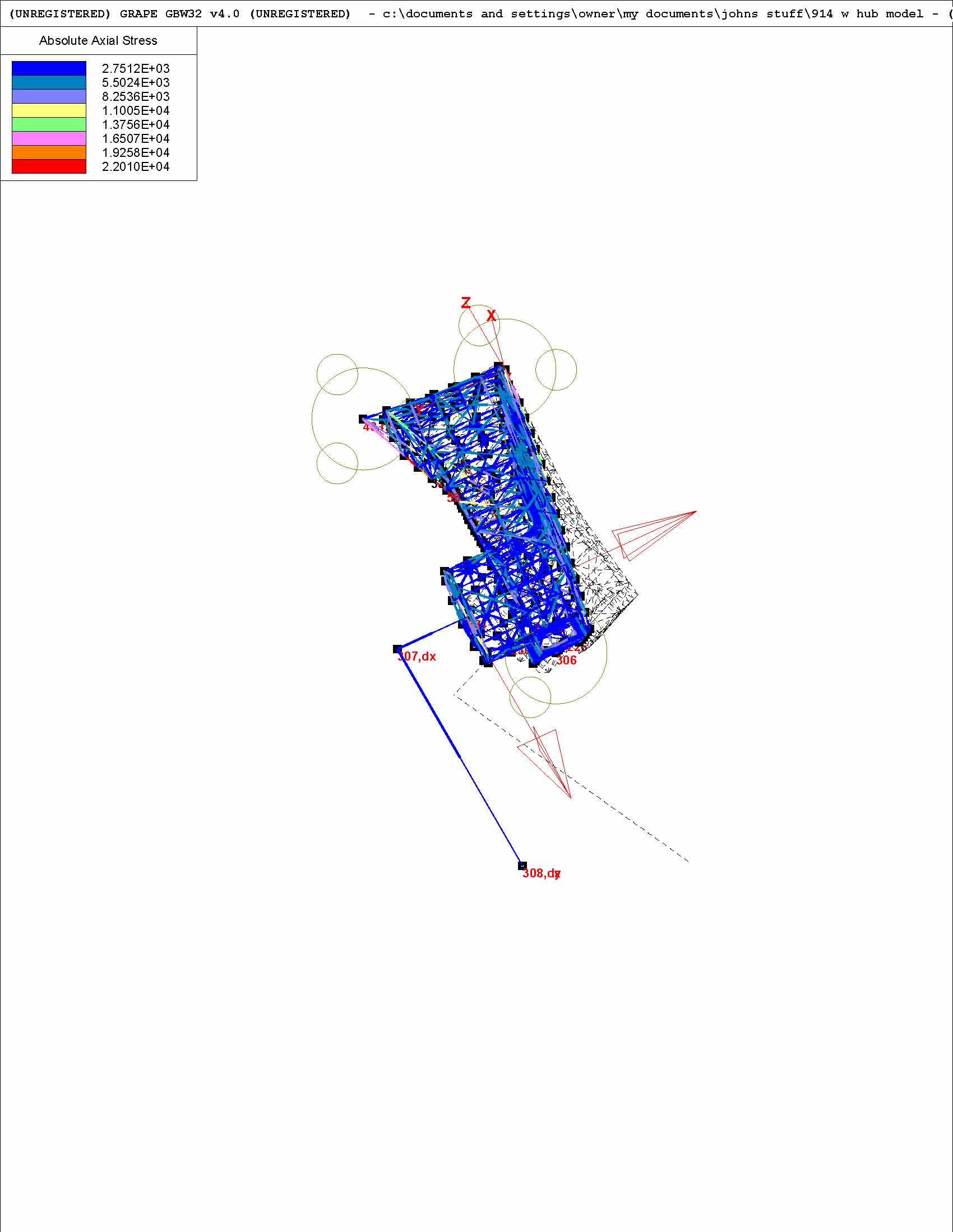
Posted by: jluetjen Jan 19 2006, 07:54 AM
And one more view that reflects Chris's mark-up above.
Attached thumbnail(s)
Posted by: Racer Chris Jan 19 2006, 08:02 AM
Here's the updated data table resized to fit.
Attached image(s)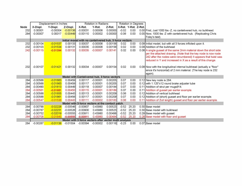
Posted by: Racer Chris Jan 19 2006, 08:31 AM
OK. Here you go --
I like what I see now. I do still have a couple of minor issues:
1) Can you reduce the displaced skeleton view to 10x instead of 100x. I think that it over-dramatizes the situation currently.
2) I want the outboard pivot location moved closer to node 284. The pivot axis properly should be perpendicular to the inner box surface. The distance of node 284 from the pivot axis will be approximately correct with this change.
3) I'm picking nits now, but - since the arm is mounted to the car with the pivot axis at a 12.5 degreee angle the tube connecting node 284 should be at such an angle, the lateral force should also be at the same angle, and the vertical up force should be moved forward a corresponding amount.
These changes would satisfy me that we have modeled a trailing arm as well as GRAPE can do for us within reason.
... but since they ignore braking and other lateral forces --
... the arm never sees a positive Z force at the bottom of the arm...
... do the math so that the answer results in a single torque being applied at point 284.
Posted by: Brett W Jan 19 2006, 08:38 AM
One thing to keep in mind is the shocks will provide no lateral location of the trailing arm. So restraining the shock mount will provide no usable data.
Posted by: Racer Chris Jan 19 2006, 08:45 AM
One last point for now, the rotations listed in the table don't accurately reflect the real world. I don't think this means the model isn't accurate, only that the point about which the rotations occur isn't modeled accurately. If possible, it would be better to tabulate the angular change (in 2 axes) of the surface that node 284 is at the center of.
the shocks will provide no lateral location of the trailing arm
Posted by: jluetjen Jan 19 2006, 09:12 AM
| QUOTE (Racer Chris @ Jan 19 2006, 06:31 AM) | ||
I like what I see now. I do still have a couple of minor issues: 1) Can you reduce the displaced skeleton view to 10x instead of 100x. I think that it over-dramatizes the situation currently. 2) I want the outboard pivot location moved closer to node 284. The pivot axis properly should be perpendicular to the inner box surface. The distance of node 284 from the pivot axis will be approximately correct with this change. 3) I'm picking nits now, but - since the arm is mounted to the car with the pivot axis at a 12.5 degreee angle the tube connecting node 284 should be at such an angle, the lateral force should also be at the same angle, and the vertical up force should be moved forward a corresponding amount. These changes would satisfy me that we have modeled a trailing arm as well as GRAPE can do for us within reason. |
Chris!!! Now you're "gilding lillies".
 How is any of this going to change the strategy that you use for modifying the trailing arm?
Posted by: Brett W Jan 19 2006, 10:19 AM
Duh! My bad, I should have read closer.
Posted by: Racer Chris Jan 19 2006, 04:59 PM
Chris!!! Now you're "gilding lillies". How is any of this going to change the strategy that you use for modifying the trailing arm?
LOL! I can ask can't I?
Actually, I expect that moving the outer pickup rearward, and inputing the lateral force at 12.5 degrees will have a noticeable (I don't know how significant though) effect on the data output from the model.
As long as I'm asking for the moon, I would also love to see the effect of the lateral force by itself, and the torque force by itself.
John, can you explain what calculation is used to produce the rotation numbers in the table? Do you have control over that calculation?
Posted by: jluetjen Jan 19 2006, 05:50 PM
| QUOTE |
| LOL! I can ask can't I? |

| QUOTE |
| Actually, I expect that moving the outer pickup rearward, and inputing the lateral force at 12.5 degrees will have a noticeable (I don't know how significant though) effect on the data output from the model. |
Actually, the front pick-ups are aligned correctly against the body of the arm. The rear hub assembly was not offset by an angle -- so that's the angle that is not reflected. Moving that back by ~6 degrees is not going to make a huge difference since the large diameter tube that the hub is attached to connects to the arm across a wide area.
| QUOTE |
| As long as I'm asking for the moon, I would also love to see the effect of the lateral force by itself, and the torque force by itself. |
How do I say this nicely?.... No.
| QUOTE |
| John, can you explain what calculation is used to produce the rotation numbers in the table? Do you have control over that calculation? |
Dammit Chris! I'm a salesman -- not a mathematician. That means I was smart enough to recruit to my team (aka: marry) an engineer with a master's degree who grunted through 6 years of advanced college level math rather then take the classes myself.
The other thing that I learned in B-School (in addition to strategic acqusitions) is delegation.
I just emailed to you a copy of the software and the base model.

BTW: Grape is Shareware that can be downloaded from http://www.grapesoftware.mb.ca/
Posted by: jluetjen Jan 19 2006, 06:23 PM
Oh yeah, here's the latest data table. Note that the rough order of incremental improvement for each strategy is consistent even as we change different force strategies. To my simple mind this suggests that the results will be fairly consistent even if you change an angle here or a few pounds there.
Attached thumbnail(s)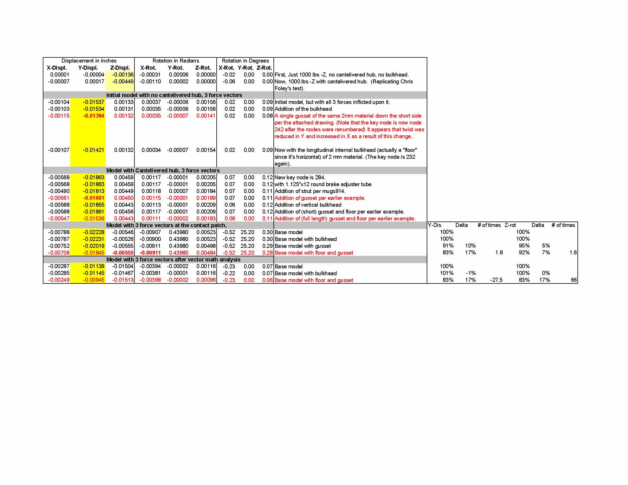
Posted by: Racer Chris Jan 19 2006, 08:48 PM
Actually, the front pick-ups are aligned correctly against the body of the arm.
Hold a carpenter's square against the inside face of the box section and you will see what I am getting at.
John, for a salesman you make a pretty good engineer. I have been impressed with the depth you go into this sort of analysis. I really appreciate all you have done and I will find a way to repay the favor down the road. 0
I'll see if I can pick up where you left off on the model (unless I can get Tim to do it
).Thanks!!
Posted by: jluetjen Jan 20 2006, 09:09 AM
Ok -- I've been thinking that we're starting to "lose the forest for the trees". This is going to be a real challenge -- I'm going to try to be brief.
Using FAE to figure out if the answer is 0.00498 versus 0.00484 is most likely not an effective use of the tool. If you want to know the meaning of life -- it's
42. But what is the question???
To answer that I went back 243 posts to look at where we started and found these thoughts:
| QUOTE |
| How flexible do you think a stock, trailing arm is? -- Specifically I am looking for rotational stiffness (ie. twist) of the trailing arm due to the tire contact patch resisting sideways sliding of the car. I'm only interested in forces greater than 1G during cornering. |
and...
| QUOTE |
| you could take your invesitgation to another level, and find where the trailing arm needs to be reinforced. |
and...
| QUOTE |
| I only want it to limit the flex from cornering loads. |
and finally this fairly pithy problem statement:
| QUOTE |
| A stock trailing arm definitely isn't stiff enough for a competition car running on slicks. |
(
 If you want to jump to my proposal and skip the long winded monologue, it's at the bottom.)
What we've learned along the way since they consisentanly came out in our tests and model -- no matter what we did to them.
1) The stock arm does flex.
2) Adding an internal bulkhead stiffens it some.
3) Adding an external gusset stiffens it more.
4) Combining the two approaches stiffens it even more
5) There are some concentrated stresses in the hub area (where Porsche's designers kindly designed in a fairly massive piece) and where the arm attaches to the outer end of the front pivot tube.
Some things that we already knew
1) Weight is evil
2) Stiffness increases with the cross sectional area and to a lesser degree by filling in internal voids.
Putting these factors all together I modified the spreadsheet to take into account the extra material being added by each solution (assuming it's all 2mm thick steel) and then compared this to the reduction in Y-displacement and Z-Rotation (which both impact toe). I then tried to optomise the solution some based on the earlier approaches and rather then combining the external gusset with an internal "floor", I tried triangulating the top edge of the gusset to the corners of the arm's original box section. The result?
A solution that is stiffer then all of the previous options, but uses less material then the next stiffest option. But even though, the best "stiffness versus weight gain" option remains the original simple external gusset.
My Final Recommendations!
1) For the lightest solution, weld a lengthwise external gusset to the arm.
2) For the strongest solution, weld additional pieces from the exposed edge of the gusset down to the arm, thus creating a "peaked roof" type of structure.
No matter what you do, doubling the thickness of the material in the area near the outer half of the front pivot tube will essentially cut the surface stresses in that area by half (same stress, double the material) which is a good thing.
Now back to my day job!

Attached image(s)
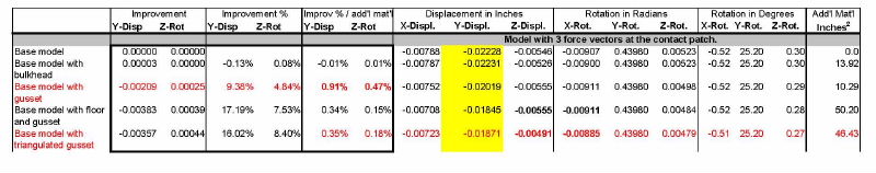
Posted by: jluetjen Jan 20 2006, 09:11 AM
Here's the overhead view of the gusset with the "peaked roof" results.
Attached thumbnail(s)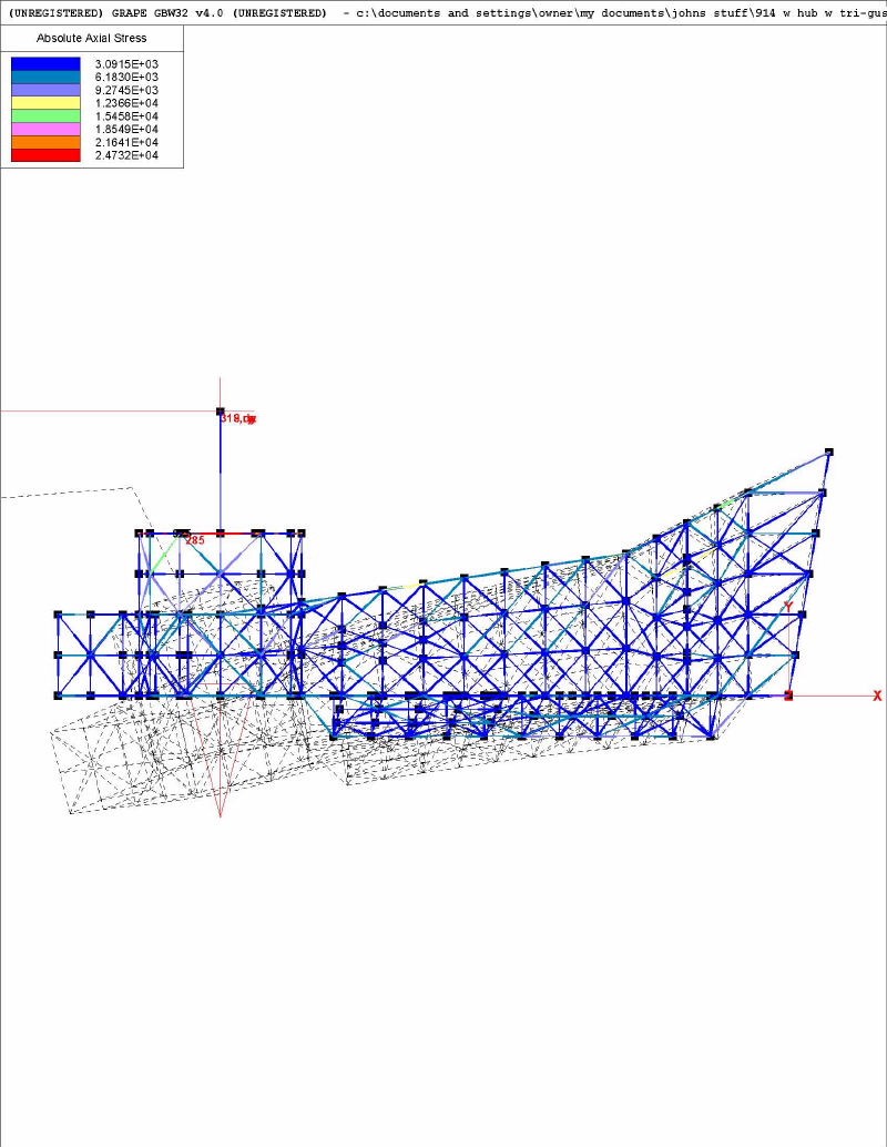
Posted by: jluetjen Jan 20 2006, 09:17 AM
A view from the outside of the arm (when mounted) showing the area of highest stresses.
Attached thumbnail(s)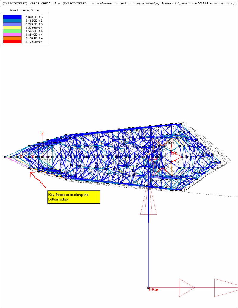
Posted by: jluetjen Jan 20 2006, 09:18 AM
Finally an "edge on" view showing the "peaked roof" structure that I discussed showed the best stiffness improvement.
Attached thumbnail(s)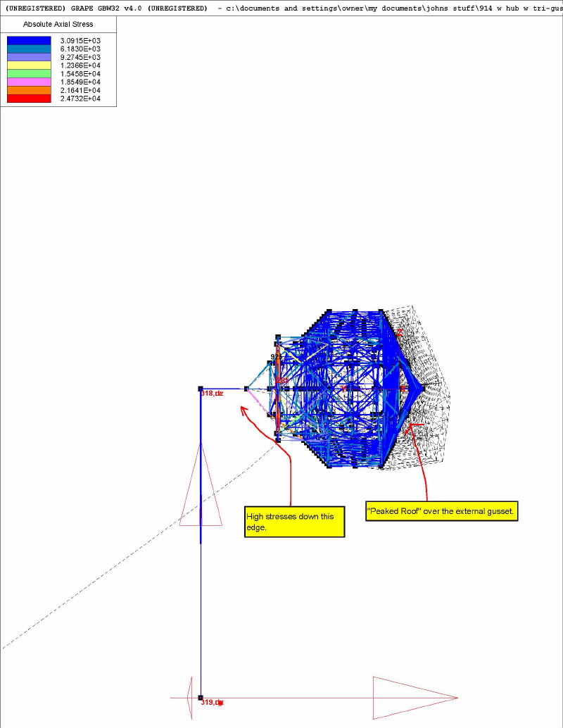
Powered by Invision Power Board (http://www.invisionboard.com)
© Invision Power Services (http://www.invisionpower.com)