Printable Version of Topic
Click here to view this topic in its original format
914World.com _ 914World Garage _ Rebuilding my race car
Posted by: slugmika Dec 29 2005, 02:55 AM
I had to make it public. That's the only way i'am going to get anything done.
So, i had to convert my rear suspension to multi link, raise the front suspension, built a new pedalbox, rebuilt the engine and tranny, make attachemets for new fg flared rear and front fenders, make a new carbon top, glue the new heated windshield, paint the car and lots of other stuff.
I will post pictures when ever i have any progress.
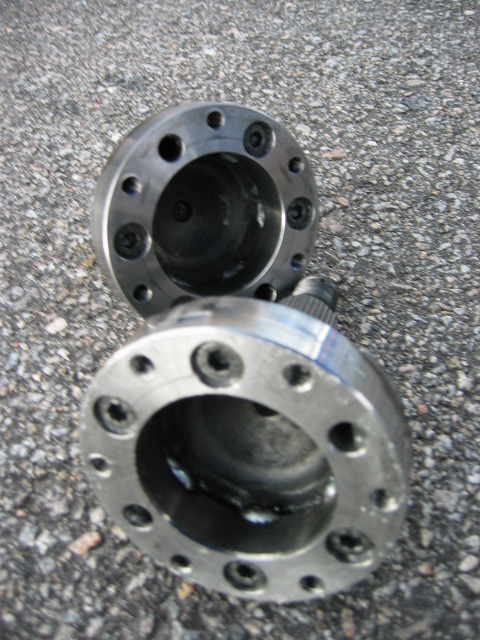
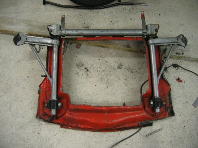
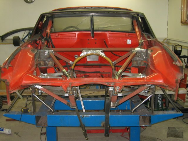
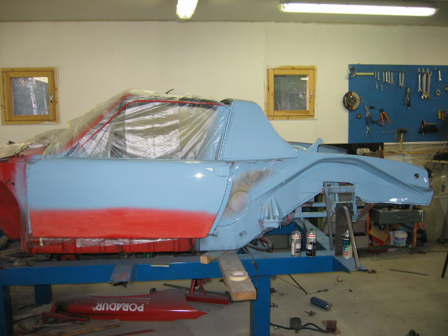
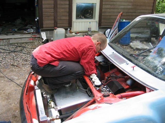
Here is the starting point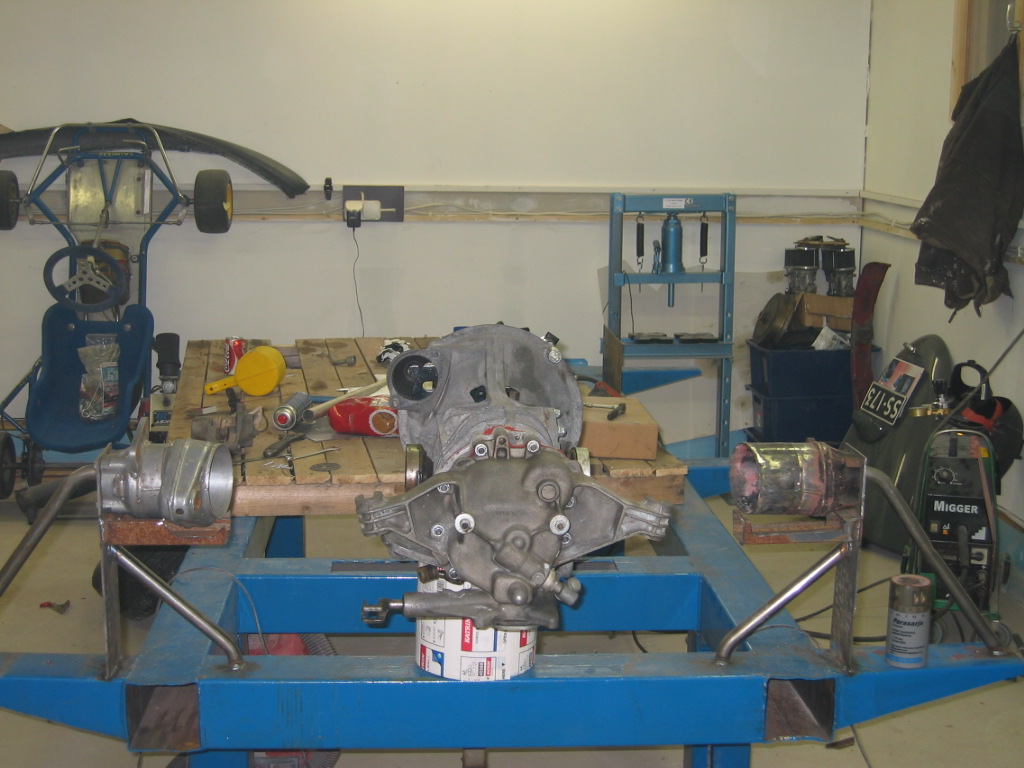
hub's are attached to table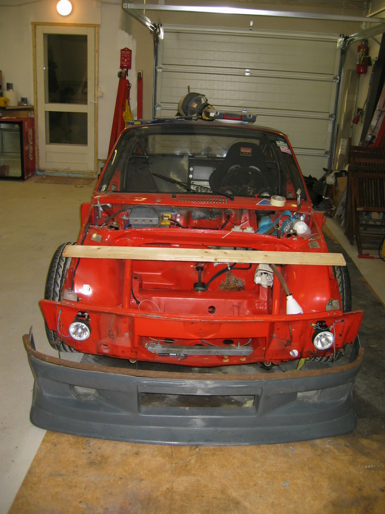
lower part of the new front
i'll put more pictures later
Posted by: URY914 Dec 29 2005, 07:21 AM
Sounds easy enough. You should be done around 2008.
Good luck. 
Paul
Posted by: slugmika Dec 29 2005, 07:31 AM
According to Historic Race Finland's 2006 schedule, it will be ready 27th of May 2006 Wanna make a bet? 
Maybe i need to skip few things  but car is going to be in Botniaring race track and have engine & gearbox rebuilt and new suspension in that day.
Mika
Posted by: Jeroen Dec 29 2005, 07:58 AM
where did you get that front bumper/spoiler?
keep us posted... looks like lots of fun stuff!
PS... I got your PM and I'll look into it real soon!
Posted by: d914 Dec 29 2005, 08:30 AM
ditto on the front bumper, I don't have to be legal for anything these days and I like that one piece unit..???
Posted by: xitspd Dec 29 2005, 08:35 AM
 Mika,
Mika,
Did you get my Christmas Card? That's quite a project that you are starting! Do you still need my front and rear FG quarter panels? Give my best regards to badJuha when you see him next. Take care and keep the pictures coming.
Dan
Posted by: dougcoup Dec 29 2005, 09:21 AM
great project, i would love to see it progress. I am impressed.
I too am building up my race car this winter, I loved the posts of brads car before.
I would love to see more photos of your fabrication throughout the car.
doug
Posted by: Brett W Dec 29 2005, 10:02 AM
I have been looking for an option for out bearings and stuff to use on my own custom rear suspension setup. I just found out about the S10 hubs and micro stubs. You can get many different options, plus the parts are available at Autozone and NAPA. I am trying to find the website. My brain has failed me. I'll get back to you.
Looks like a good plan.
Posted by: slugmika Dec 29 2005, 11:35 AM
Hi guys
Yes this i a big project and i really need all the help i can get. Luckily there is people like BadJuha, Timo, Dan and all you helpful guys in 914club to make it easier  .
.
Jeroen, it seems that you have become the official designer of team bogeyracing
The front bumper is lower part of the Opel Omega Evo somethings front end.
The rusty iron bar which you can see in the picture is going to be part of the upper bumper, it's hard to explain but i will take some pictures.
Dan, yes i just got back from north and the card was waiting, i'll get back to you privately. Yes i really need those rear FG quarter panels. I have the addres and number to Finnish guy who is shipping containers to Finland all the time. He's located in Compton.
Now back to work
Mika
Posted by: slugmika Dec 30 2005, 02:05 PM
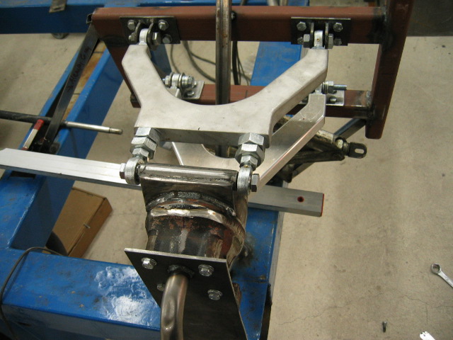
I had couple of hours to work on suspension today.
upper link 80% ready, actually these first ones i'am only using as a tool to make jig.
this upper will have adjuster in the front link. that is used for adjusting toe.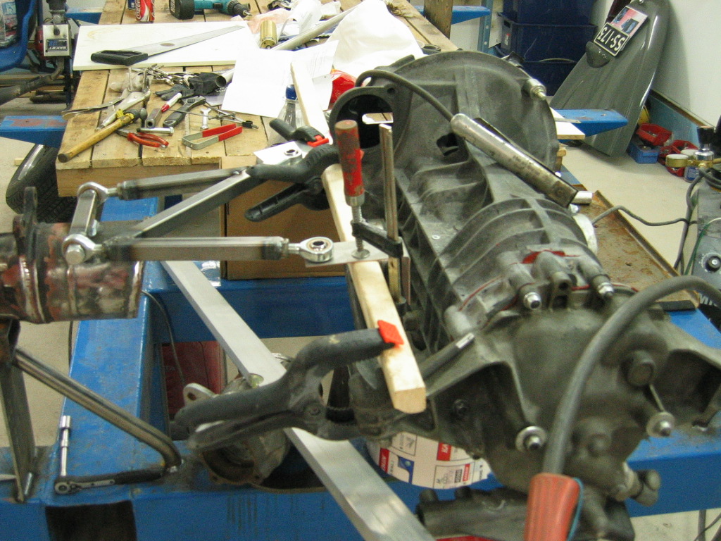
Posted by: Jeroen Dec 30 2005, 06:50 PM
awesome!
can't wait for more

Posted by: Aaron Cox Dec 30 2005, 09:40 PM
what are all the links going to mount to?
looks wicked mika!!!
BTW - why are ya using a tailshift? (just for mockup i hope)
Posted by: Aaron Cox Dec 30 2005, 09:41 PM
and what trans flanges are those?? (915? adapters? BUS??? 930???)
what axles are ya using?
Posted by: Headrage Dec 30 2005, 09:50 PM
| QUOTE (slugmika @ Dec 29 2005, 09:35 AM) |
| Yes i really need those rear FG quarter panels. I have the addres and number to Finnish guy who is shipping containers to Finland all the time. He's located in Compton. |
Really???
The only reason I ask is that I go through the area every week.
Can I help?
Please don't get me shot....

Posted by: Travis Neff Dec 30 2005, 09:54 PM
Aaron, check Slugmika's blog, bus cv adapters - I love the front swaybar!
Posted by: Aaron Cox Dec 30 2005, 09:57 PM
| QUOTE (Travis Neff @ Dec 30 2005, 08:54 PM) |
| Aaron, check Slugmika's blog, bus cv adapters - I love the front swaybar! |
shoulda known! very cool
 bus cv's he says
Posted by: xitspd Dec 30 2005, 10:20 PM
| QUOTE (slugmika @ Dec 30 2005, 12:05 PM) |
| I had couple of hours to work on suspension today. upper link 80% ready, actually these first ones i'am only using as a tool to make jig. this upper will have adjuster in the front link. that is used for adjusting toe.   |
Mika, Very, very cool! Are you using a tail shifter or is it a mock-up trans? Side shifters are much easier to use. Let me know what parts you need and I will try to help. Looks like you have great fabricating experience. I hope your shop is heated.......................
Dan
Attached image(s)
Posted by: slugmika Dec 31 2005, 01:23 AM
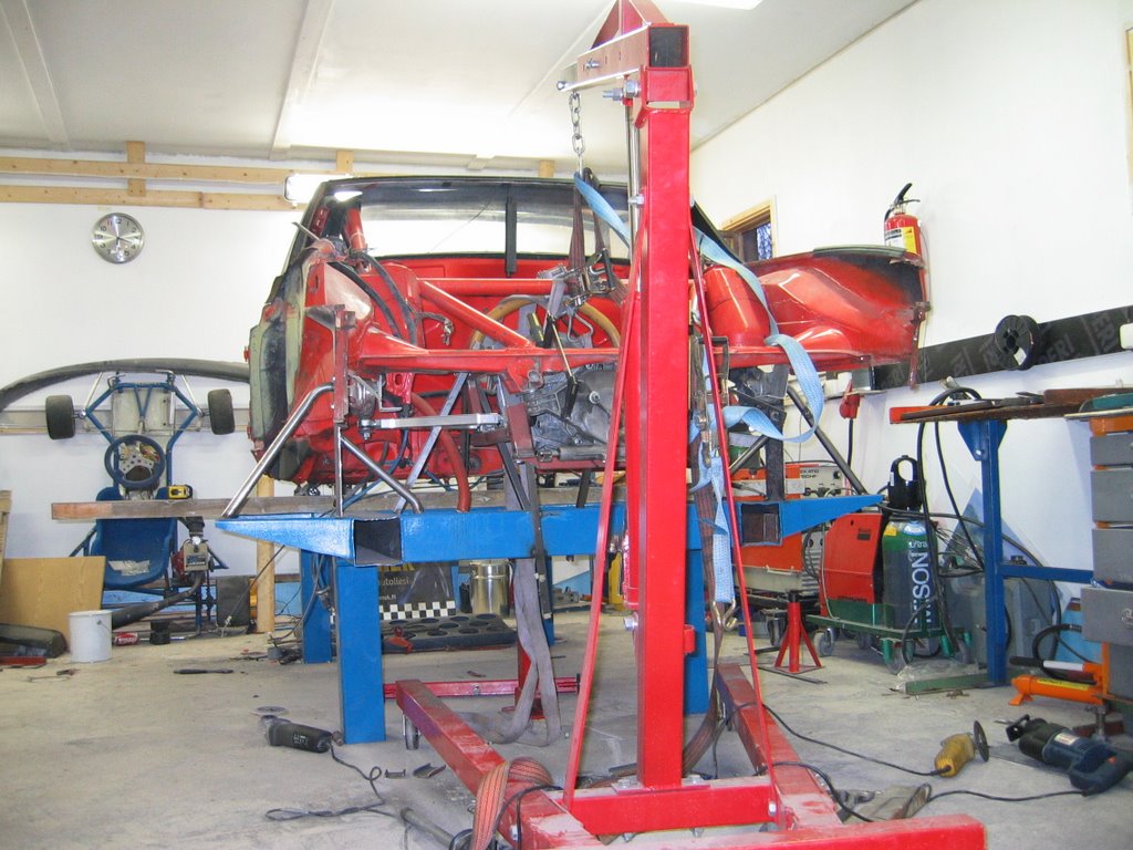
Aaron- next will be the upper mount's, i will make those in a place of that wood stick. For now i will fabricate a frame which is welded to my chassis table. when all is done and check measured, i will lift the body over completed suspension and weld it to my gage and tub.
Yes those are bus cv's and bus axles with adapters, works really well.
Headrage-I'am sure you can help. When they get the parts to Compton in a box which has my name and address, rest is easy. Many times when i have tried to buy something it seems to be problem to sendt those directly to Finland or even to Compton.
Dan-If you look closely it is a side shifter tranny. I broke all my side shifter end covers so i had to use one from tail shifter. So i could use side shifter end piece if you guys have spare ones.
Fabricating is easy part of this project, it is the planning that has took my time. And yes Dan my carage is heated. It is insulated as a normal house in Finland and has floor heating and infra red heaters for paintin.
I will try to finish the upper mount today and take some pictures.
Mika
Posted by: xitspd Dec 31 2005, 10:30 AM
Mika,
Next week I will send you one of my spare 901 side shifter covers and the Porsche magazines I have been collecting for you. Happy New Year to all my Finnish friends. That includes Timo and BadJuha.
Posted by: andys Dec 31 2005, 12:08 PM
Mika,
Great project; I wish you good luck. Are the pickup points on the chassis going to have any vertical adjustment? I'm curious as to how you plan to establish the appropriate geometry; i.e. instant center, roll center, camber curve, gain, etc, etc.
Andys
Posted by: Mueller Dec 31 2005, 01:19 PM
neat...very inspiring....I wouldn't even know how to start a project like that.....
Posted by: slugmika Jan 1 2006, 02:04 AM
Happy New Year to all of you Yesterday i didn't had chance to do much because our Armi doughter got sick and we were at the hospital till 11.
Thanks Dan, i will forward your greetings to Juha. Btw did you get my email 3 weeks ago? If you are coming to Finland next summer we'll take you to Ahvenisto race track to test our cars. Our team is organicing a 6 hours endurance race for aircooled volkswagens in Ahvenisto. If you or any other 914club member is interrested, Bogeyracing could sponsor a car for you.
"Great project; I wish you good luck. Are the pickup points on the chassis going to have any vertical adjustment? I'm curious as to how you plan to establish the appropriate geometry; i.e. instant center, roll center, camber curve, gain, etc, etc.
Links will be straight so the roll center is in ground level. Uniballs will attach to pickup point horizontaly and there will be room to space those up and down. Main camber curve is from the design and amount of it is adjusted from the uniballs. Toe will be adjusted from the fron upper link. That will have adjuster piece in the midle of the link and unibal. adjuster will have right and left side threads in it. Biggest ? is the anti squat but i maybe just try my best gues and put it there. That is in a case that i can't figure out easy way to make it adjustable. As i'am not an engineer, it takes time to plan these but i have noticed that best way to me to do these kind of things is just start fabricating and making changes. So if you have good ideas how to make this setup better, feel free to speak.
Mueller- For me the starting is normally the hardest part
Mika
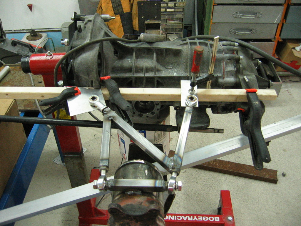
Posted by: slugmika Jan 1 2006, 09:55 AM
Upper pick up point in its place. I made the actual pick up's bolted to the frame so if i need more radical changes i can just make different kind of pick up points.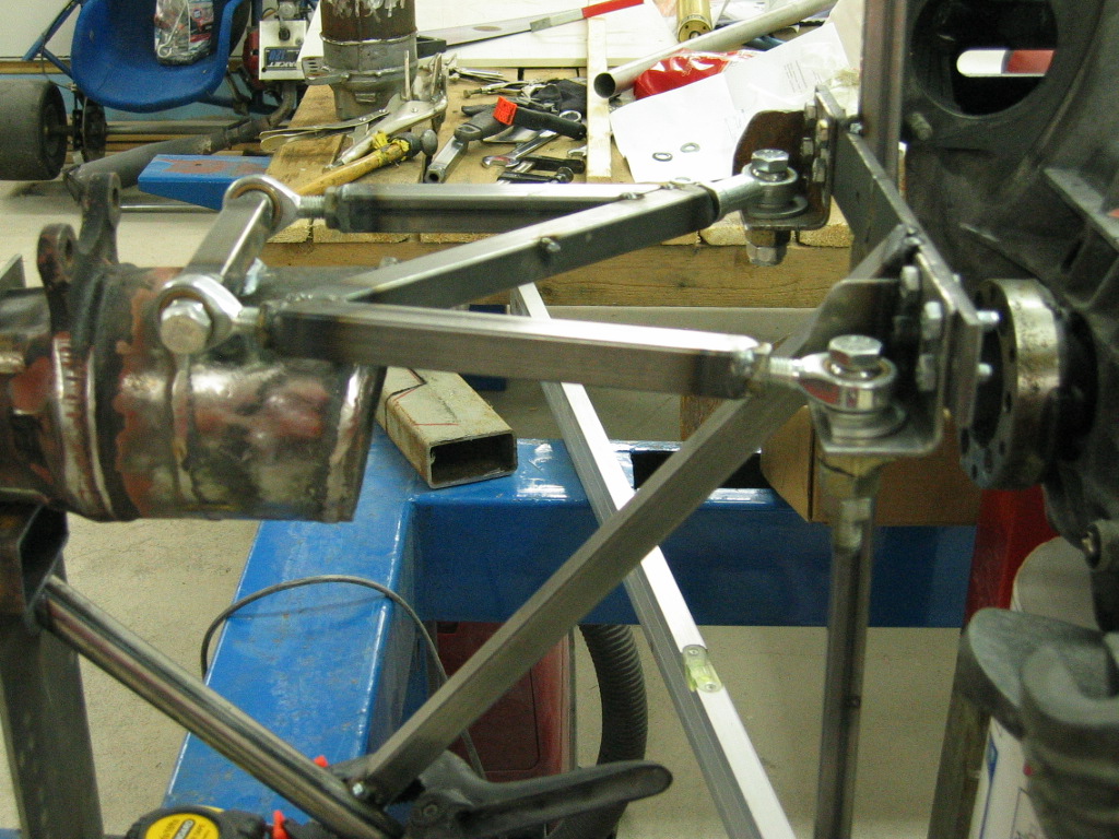
Next will be the lower frame part, pick up's and lower links.
Now it is much easier when i finally have upper links with pick up points and frame part ready. Most of my time today went to measuring and checking that everything is level and pointing in a same direction. I can use this upper frame as my reference point for the others.
Here is my garage 5 minutes ago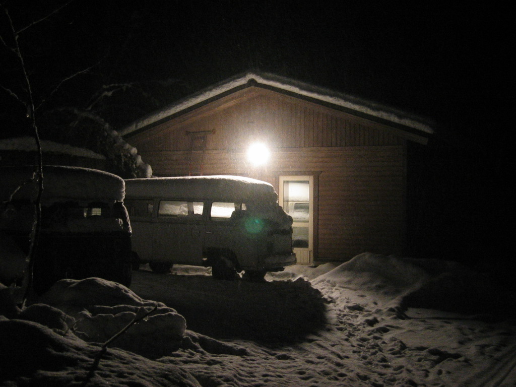
-Mika-
Posted by: Jeroen Jan 1 2006, 12:14 PM
did you just weld nuts to the ends of the square tubing?
just curious...
why not mount the inboard rod ends in a vertical plane as well (like the ones at the hub)
and maybe mount them in double shear?
Posted by: slugmika Jan 1 2006, 12:53 PM
Hi Jeroen
Yes i just welded nuts. But these are not the ones i will be using. These are just for making a template to jig. Thats why there is different kind of unibals and some of the parts are not welded as they should.
I just like it this way because it is easier to adjust these with shims. I was thinking about vertical but i don't know, thís was just my idea of easy. 
They will be in double shear (if it is like between two layers of metal[my english  ])
])
-Mika-
did you just weld nuts to the ends of the square tubing?
just curious...
why not mount the inboard rod ends in a vertical plane as well (like the ones at the hub)
and maybe mount them in double shear?
Posted by: 914_1.8t Jan 18 2006, 03:30 AM
Any update on this? Very interested to see how this comes out.
Posted by: slugmika Jan 21 2006, 01:37 AM
Hi
i'we been sick so there's not so much progress.
i will post some pictures of my new aluminium upper
arms and current status later today.
one thing that i did when i was sick at home, i bought a aluminium Koni
douple adjustable shocks from ebay.
later
Mika
Posted by: Racer Chris Jan 21 2006, 02:08 AM
Wow, I'm impressed Mika!
It seems like only a few weeks ago you were interested in raising the stock trailing arm pickups.
Very cool!
Posted by: slugmika Jan 21 2006, 10:04 AM
Hi Chris.
Thats true, after that i noticed that all my trailing arms, includint the current ones are bendt. It is really hard to find stock trailing arms in Finland and it would have taken too much time to build custom ones for stock mounts.
I decided that it is easier to make the rear this way.
Here is the new frame for trailing arms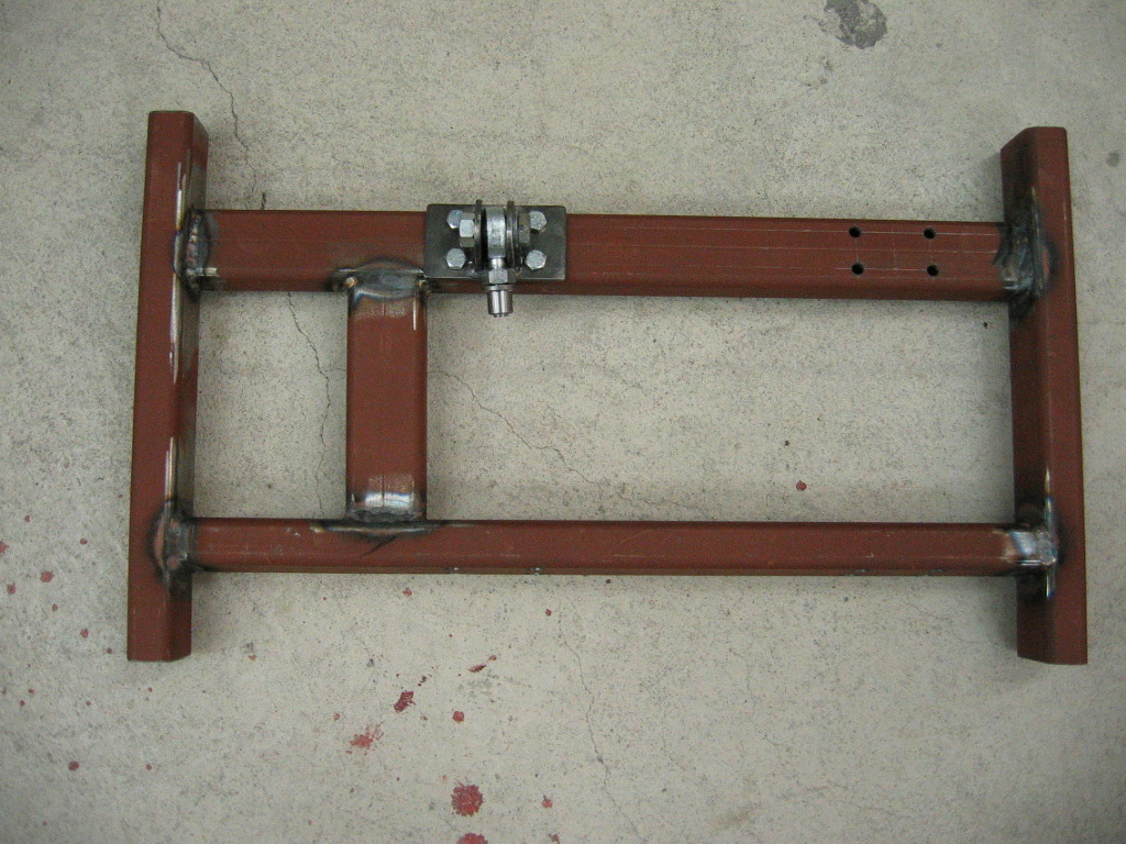
I finally tested my tig welder with this one. I bought the welder 2 years ago but this was the first time i used it, it was really fun.
close up of the first of these thingys (dont know the word in english)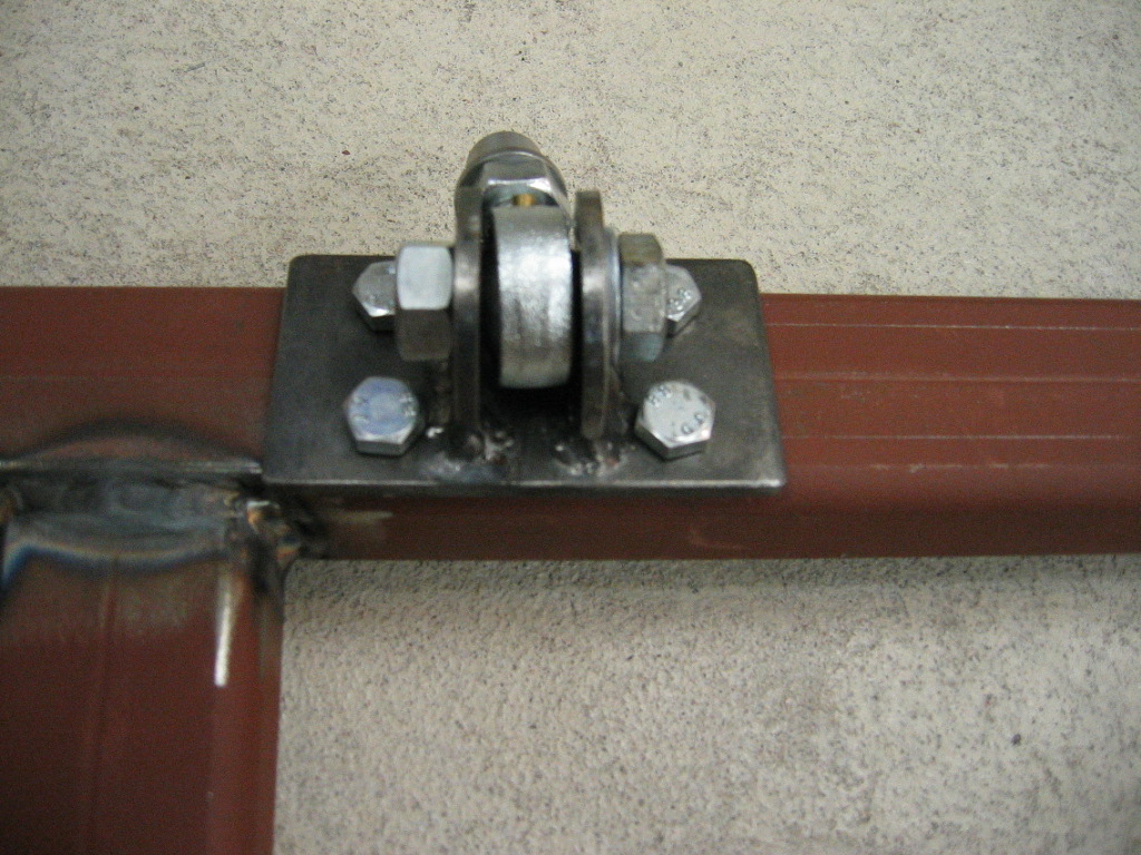
And here is new upper arms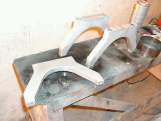
I'll take better pictures later today.
-Mika
Posted by: messix Jan 21 2006, 11:40 AM
heim joint
Posted by: slugmika Jan 21 2006, 01:45 PM
No, i mean the thing that i attach the heim joint.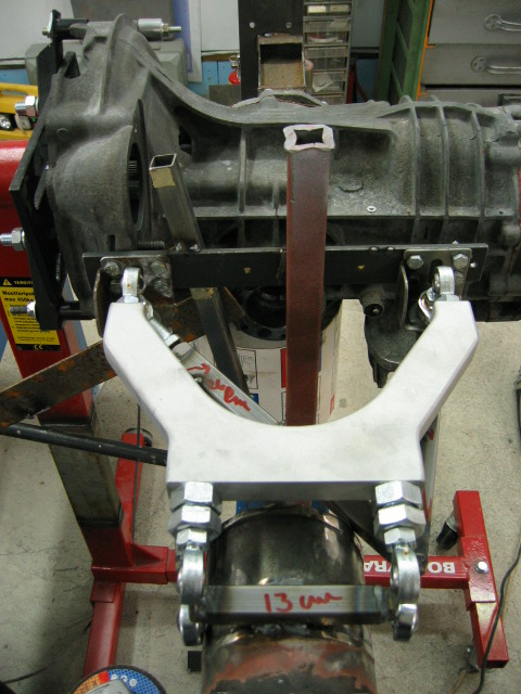
Tomorrow i have more time to work on car. There is not
so much to do other than stay inside, its -13F here <!-- emo&;) --><!-- endemo -->
-Mika
Posted by: Jeroen Jan 21 2006, 08:30 PM
those susp arms look sweeeeet!!!
Posted by: messix Jan 21 2006, 08:49 PM
bracket, or mount?
Posted by: slugmika Jan 26 2006, 02:42 AM
I'am still sick
Luckily i have had couple of helpers so some progress.
All the brackets are made and so are the upper and lower arms.
Frame in this picture is about in a right place.
Next thing is to weld those frames to table.
When those are in a table and arms connected to hubs, i can lift
the body to its place.
Mika
Posted by: slugmika Jan 30 2006, 01:22 AM
Left side is finally finished.
Hub is ready and whole assembly is welded to table.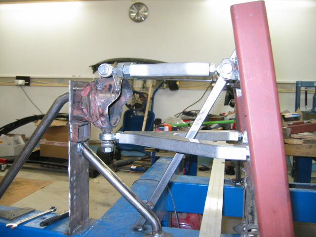
Tested the suspension travel yesterday and i was happy.
Hubs are going to be made of aluminium later.
Next thing is to make the right side ready and start building
the front axle.
Actually i still need to make the mount for new Koni's to those hubs.
Posted by: racerx7 Jan 30 2006, 01:32 AM
It looks very impressive.
How do you go about figuring, camber, caster, rear bump steer angels, roll center?? Do you have to know the wheel base vs width in relation to the front and rear? Do you have to factor weight bias? Do have to know ahead of time what size tire/width you will be running?
I have always wanted to do that.
Posted by: slugmika Jan 30 2006, 03:06 AM
I'we been drawing and simulating these in paper. Camber gain is calculated to 2" suspension travel (bump) and it is from static zero to 5mm in 2". That can be adjusted from upper or lower trailing arms. Caster is zero but can be adjusted with different upper mounts. Roll center is in ground level because of the instant center is in infinity (horizontal arms). Roll center is adjusted by changing the upper arms angle. Toe is adjusted from the bolts in upper arms.
I made this set up with stock wheel base and width (if i understand what you mean). I'am trying not to mess the current weight bias much. I'we buildt this set up for 245/50/16 wheels, so hubs are in a center of that.
When i'am lifting the body to this new suspension, i will set up the ride height to about 3".
I need to figure out the front next. Thought about raising the spindles 1" and maybe the whole axle set up 1".
I'am not a professional in this kind of things. I just ordered some books and tried to search 914club and other pages to find info. If someone notices something fatally wrong in my build up please inform me. I needed to just built this and start testing, i don't think it is worse than the original setup.
Mika
Posted by: racerx7 Jan 30 2006, 04:19 AM
First let me say you know a lot more than I do. I have only read books. This stuff fascinates me.
When I meant toe, I meant toe when your car is in a turn and hit a bump. What does the
rear tires do then? Do the tires toe in. toe out. by how much. Is there any toe dialed in
for acceleration or braking? It hurts my head to think about it:)
I am sure what ever you are making has to be better than the stock 914 suspension rear
geometry. Flame suite on.
I am not 100% sure about this but some cars like the old 240z the rear suspension seemed liked the toe
does not change on it through out its travel. While the 914 stock suspension does. That long semi-trailing arm creates toe & camber changes as it goes through its travel. It seems like the tire would have a lot of leverage againts the rear suspension of a 914. I think it would be very difficult for the rear suspension to make the tire go where it suspose to go.
When you design the rear suspension did you have to take into a account how the front suspension works (camber changes, roll centers, etc..). Did you have to take into account the wheel base? Or can you just design the rear suspension independent of the front?
As an example I wonder what would happen if took the rear suspension off the 1992-1995 rx7. car
with double wishbone front rear weight 50/50 and put it on a 1987 mustang. different wheel base.
the front suspension is strut. I am guessing the wheel bases must be different and the mustang
is more like 65/45. I would think this car would do wierd things in a turn hitting a bump.
I can not wait to see the finish product and the test results.
Posted by: slugmika Jan 30 2006, 05:09 AM
At the moment toe is not changing thru the travel or due acceleration or braking.
My problems have mainly been in rear so i haven't planned so radical changes to front.
We'll see how much this changes when the rear end starts to work better
There is couple of theories about front wheel base vs rear. I think i will try to get those pretty close to each other. When i get my new fg fenders and quarter panels then i'll know how wide front i can run. I'am going to make the above mentioned changes to get the front rc closer the new rear suspensions rc and start with otherwise original front suspension.
Mika
Posted by: 914Timo Jan 30 2006, 09:52 AM
WOOO-HOOOO !!!! 
Nice progress. Those suspension arms looks VERY nice 
Posted by: slugmika Jan 30 2006, 10:01 AM
Thanks Timo
As you can see, i did it as we planned the other day.
Thanks for your advises.
I'am still sick so progress is quite slow.
Mika
Posted by: 914Timo Jan 30 2006, 10:59 AM
Oh, really. I am glad if my thoughts help you.
Hope you´ll get well soon.
Have you heard anything about those parts coming to me ?? As soon as you get them I could come and see your project. I can hardly wait to see those suspension arms in live. They are ..... 
Posted by: turbo914v8 Jan 30 2006, 02:47 PM
Your work is off the hook. When it’s all done, I think you all your troubles and hard work will pay off. I for one would pay you to supply me with parts, finished product as an upgrade for my 914. I think that a lot of 914 owners here probably feel the same. Keep up the great work and just remember when you’re famous that I am first in line for your products. 
Posted by: Jeroen Jan 30 2006, 04:42 PM
| QUOTE (turbo914v8 @ Jan 30 2006, 09:47 PM) |
| I for one would pay you to supply me with parts |

put me second in line
Posted by: biggy72 Jan 30 2006, 06:31 PM
I was just wondering if you have the steel heim joints threaded directly into the aluminum. If it is it may cause some gauling, and may not be the easiest thing in the world when you go to adjust it.
Generally you want to keep your rear track width a little more narrow than the front as this allows the rear of the car to pivot easier and it will follow the front better. This might not be possible depending on how big of a motor you're running and how wide of tires you need to keep traction, but generally it's what I've seen as a rule of thumb to try to keep with.
it looks like your lower control arms are shorter than your uppers and that's the right idea there, but I'm not a big fan of keeping both of the a arms parallel. It doesn't have an instant center and so the roll center does weird things (from what I've read). I just got done designing some suspension geometry for a formula sae car and I put the rear roll center right at ground level when it's static, and it goes more below ground under bump. From what I've read this helps eleviate the need for a sway bar. Over the next couple years I'll get to experiment with a few different geometry set ups and we'll see what each change does.
Almost everything I just said is only from research and I haven't put it on a car yet.... well except the aluminum a arm thing. I'm in the process of building steel a arms that are lighter and won't fatigue like the aluminum does.
Posted by: slugmika Jan 31 2006, 01:21 AM
Thanks for your comments guys.
"I was just wondering if you have the steel heim joints threaded directly into the aluminum. If it is it may cause some gauling, and may not be the easiest thing in the world when you go to adjust it."
-Yes those are threaded directly into the aluminium. I am using Castrols anti corrosion lubricant with those. I haven't had any problems with same kind of connections earlier with this Castrol stuff. If we have problems with gauling, we'll add steel insert to the arms.
"Generally you want to keep your rear track width a little more narrow than the front as this allows the rear of the car to pivot easier and it will follow the front better. This might not be possible depending on how big of a motor you're running and how wide of tires you need to keep traction, but generally it's what I've seen as a rule of thumb to try to keep with."
-Thats true, i will try to keep the original difference in my car. Last season we had much wider rear than front and it was working better than original set up but that was because of other problems in rear.
"it looks like your lower control arms are shorter than your uppers and that's the right idea there, but I'm not a big fan of keeping both of the a arms parallel. It doesn't have an instant center and so the roll center does weird things (from what I've read)."
-Actually upper are shorter . Reason for parallel arms is that it's easy starting point. Now i can adjust roll and instant center just by changing the upper arms inner pivot point. I'am sure this is not the best way to do it but i think this is zillion time better than my cars original set up.
"I just got done designing some suspension geometry for a formula sae car and I put the rear roll center right at ground level when it's static, and it goes more below ground under bump. From what I've read this helps eleviate the need for a sway bar. Over the next couple years I'll get to experiment with a few different geometry set ups and we'll see what each change does."
-So you must have nice software to design these things? I really should have found someone with suspension software before i started this project. I'we been checking those sae formulas and those seem to be really well thought machines. I'am sure your design is in totally different level than mine but i'we done my best. My design might not be "optimal" but i think it is nice starting point for testing.
"Almost everything I just said is only from research and I haven't put it on a car yet.... well except the aluminum a arm thing. I'm in the process of building steel a arms that are lighter and won't fatigue like the aluminum does."
-I'am not worried about the fatigue of these aluminium arms but i'am also building steel a arms to test few things.
Thanks for your comments, keep em coming
-Mika-
Posted by: biggy72 Jan 31 2006, 01:56 AM
ya I meant the top arms were shorter, don't know why I said that.
Well the software I've got isn't really suspension software, it's just solid works, just a cad drawing program. It lets you set points on top of other points and then adjust one thing or the other to see how the articulation works. Makes it really easy to see the camber curve, instant centers, roll centers, and you can draw up any parts and test them under different conditions to see where the weak points will be. I'm not a pro on the program at all. I've just been teaching myself so I can apply the things to the formula car since there aren't any classes offered here for it.
While your car's not exactly a formula car alot of the things are just common to a double a arm set up. With our current car we've got the front roll center right at ground level at static height, and the rear pretty far below. The car's handling really neutral without a sway bar, but it feels really lazy when turning, and I think the roll center along with a couple other problems is causing it. We'll see how next year's car works out.
Good luck with your set up, the z link in the rear should work really well from everyone else I've seen with it, and I'm building something really similar for our new a arms.
Posted by: racerx7 Jan 31 2006, 02:31 AM
WSU Formula SAE Drivetrain Lead/ Suspension Team
http://www.mme.wsu.edu/~sae/
Please for this arm chair want to be designer, could you recommend books, software for me to look and read about.
I have always wanted to go to school just so I could enter
that contest. Maybe in my next life time.
Posted by: slugmika Jan 31 2006, 10:38 AM
ok i'll make one set of brackets which makes the rc radically below ground level so we can test that too.
Mika
ps. there has been lots of interrest about front spoiler. that is copy of Opel Omega Lotus part.
Posted by: biggy72 Jan 31 2006, 01:35 PM
| QUOTE (racerx7 @ Jan 31 2006, 12:31 AM) |
| WSU Formula SAE Drivetrain Lead/ Suspension Team http://www.mme.wsu.edu/~sae/ Please for this arm chair want to be designer, could you recommend books, software for me to look and read about. I have always wanted to go to school just so I could enter that contest. Maybe in my next life time. |
I really wouldn't go that far... It's only my second semester here, and we're a first year fsae team. I think our car is decent, but there's a steep learning curve going on right now for just about everyone involved.
As for books, there are lots, but the best overall book that we use quite a bit is Race Car Vehicle Dynamics ( http://www.sae.org/servlets/productDetail?PROD_TYP=BOOK&PROD_CD=R-280 ) and for programs we mostly just use solid works.
Really at this point I don't know much, but I'm learning quite a bit about this type of stuff right now, and hopefully I'll only pick up more as I go.
Posted by: racerx7 Jan 31 2006, 01:39 PM
Cool. Thanks. I am placing a order right. Don't tell the wife. I spent
the last two weeks selling over 150 books to make room for the
kids books. Just one little book should not make a difference right:)
Posted by: Mueller Jan 31 2006, 01:58 PM
| QUOTE (racerx7 @ Jan 31 2006, 01:31 AM) |
| WSU Formula SAE Drivetrain Lead/ Suspension Team http://www.mme.wsu.edu/~sae/ :worship: Please for this arm chair want to be designer, could you recommend books, softwarefor me to look and read about. I have always wanted to go to school just so I could enter that contest. Maybe in my next life time. |
this software has been recommended by a few people in the know

http://www.mitchellsoftware.com/
Posted by: racerx7 Jan 31 2006, 02:10 PM
| QUOTE (Mueller @ Jan 31 2006, 11:58 AM) |
| this software has been recommended by a few people in the know http://www.mitchellsoftware.com/ |
Very nice. thanks for the link.
Posted by: Mueller Jan 31 2006, 02:21 PM
| QUOTE (racerx7 @ Jan 31 2006, 01:10 PM) | ||
Very nice. thanks for the link. |
no problem....I wonder if he'd offer a group purchase discount or a networked version for multiple people
I'd like a copy, but I have a hard time justifing the price for something I'd only use a few times a year if even that much......
Posted by: stock93 Jan 31 2006, 03:10 PM
Great looking fab work!
The microstub setup BrettW was talking about can be found at http://www.kartek.com This setup is commonly used in off road buggy racing.
I've attached a picture as well.
John
Attached image(s)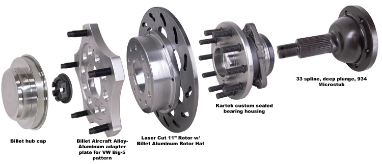
Posted by: biggy72 Jan 31 2006, 03:13 PM
I'm borrowing a book that the guy that invented the mitchell software wrote. I've heard about his program as well, but haven't ever used it since you can do everything on solid works, just have to set it up first. And since we're college students we've been kind of running on the minimalist approach.
If you don't want to learn how to use a whole program and you want to do more of a plug and chug kinda deal his program is probably much better.
Posted by: slugmika Feb 21 2006, 01:16 AM
Hi Again
I'we been sick for over month but now i'am getting better (i hope).
I don't know if i should call this progress but here is what we did last weekend.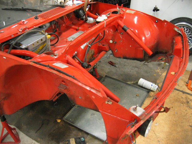
I was thinking that i just make a frame out of the 30*50mm square tube which i
use to tie the front and rear attachment points together. Then i raise the whole setup
1" and weld roll gage tubes to it. How does it sound? Do you think there is something else
i should do to make the front better? When i have the frame part ready i will put it on a table and then measure that all are square with rear axle.
Here is the rear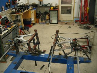
i'am trying to get the suspension ready so i can lift the car over it. This should happen in a next 3 weeks.
Then i should have the car ready for Callicott Motorsports quarter panels (thanks Dan) as they arrive.
After those are on a car, i'll paint the car using a Jeroen's design with main sponsors colours.
Then of course i still need to rebuildt the engine and gearbox.
Oh, and finish a new trailer (thanks lurker Pekka)
Mika
Posted by: alpha434 Feb 21 2006, 03:12 AM
Did Harris have anything to do with this?!?!
Posted by: slugmika Feb 21 2006, 05:11 AM
Harris?
Posted by: Jeroen Feb 21 2006, 07:37 AM
way to go Mika! I like your plans!
but since you're at it... why not make a double a-arm front suspension as well?
Posted by: rick 918-S Feb 21 2006, 08:19 AM
Nice work! I have one question. Why did you attach the lower control arm (outer hiem joint flat?) It looks like it would bind in full travel and stress the joint. I'm no chassis builder, just an observation.
Posted by: 914Timo Feb 21 2006, 08:19 AM
Jeroen, don´t even start !!! 
Mika already has a lot to do before summer. If he starts to design a new front suspension too, we don´t see him next summer at the track. 
But, maybe during next winter..... 
Posted by: 914Timo Feb 21 2006, 08:25 AM
| QUOTE |
| Why did you attach the lower control arm (outer hiem joint flat?) It looks like it would bind in full travel and stress the joint. |
I am not Mika, but.... Yes, it looks like it will bind in full travel, but it wount. I asked the same and Mika showed to me it really works.
Posted by: slugmika Feb 21 2006, 12:11 PM
Hi guys
Luckily our rules doesn't allow to change front to double A-arm.
And as Timo allready told it does work. We will add small shape to final aluminium parts so that there is even more travel. I just need total of 10cm. travel. And one more thing, that joint is taking all the braking and acc forces and it is much stronger that way.
Mika
Posted by: rick 918-S Feb 21 2006, 04:32 PM
| QUOTE (slugmika @ Feb 21 2006, 10:11 AM) |
| And one more thing, that joint is taking all the braking and acc forces and it is much stronger that way. Mika |
Oh, I get it.
Thanks
Posted by: slugmika Feb 21 2006, 11:00 PM
BTW Rick, i love your car
Posted by: slugmika Feb 22 2006, 01:24 PM
Some progress.
Front axle frame allmost ready.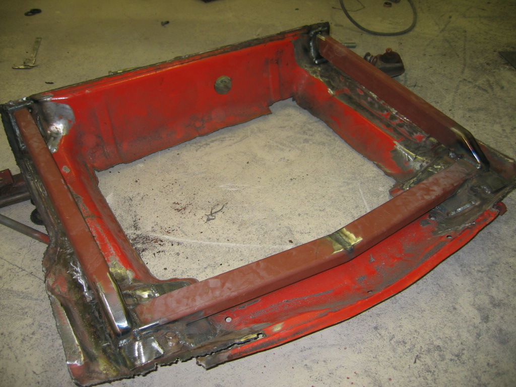
detail shot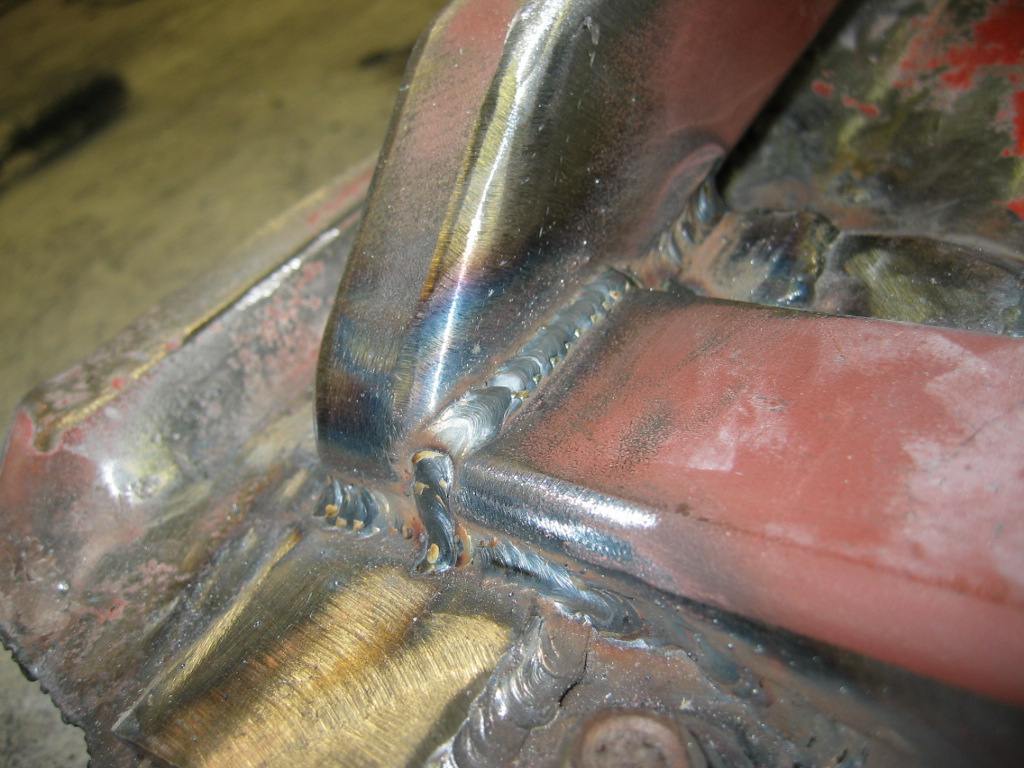
Friday i will have change to finish the frame. Then i can lift the front to table and start measuring.
Mika
Posted by: slugmika Mar 12 2006, 02:16 PM
Some progres.
We got the front axle placed in a table and corrected some misalligments. Now the front and rear are in right place and body is about to be welded. We are going to raise the front about 2" and match the rear to that. Here's some pictures. Thanks BadJuha, Topi and Henkka.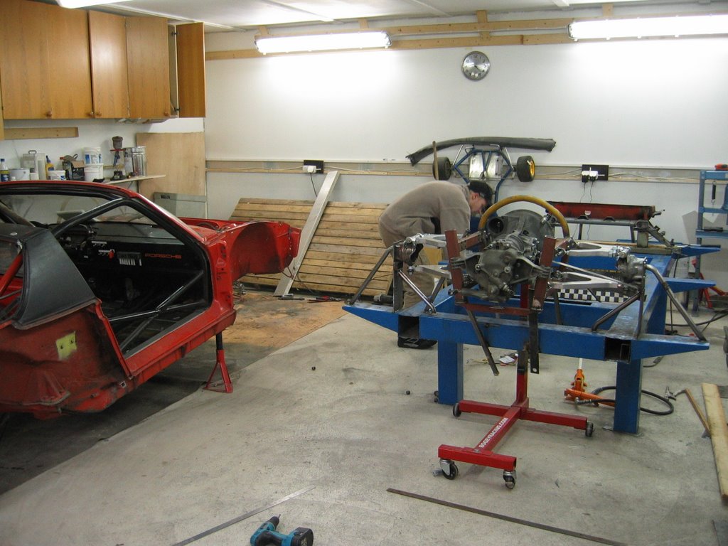
Posted by: Aaron Cox Mar 12 2006, 02:19 PM
you guys are nutz!
and i respect that 
Posted by: slugmika Mar 12 2006, 02:38 PM
Thanks Aaron, i don't know if i'am nutz or just plain stupid 
We also raised the gearbox and engine 28mm. Now there is more room for headers etc. under the car.
Posted by: Jeroen Mar 12 2006, 03:22 PM
cool!
got any pics of the front?
Posted by: slugmika Mar 13 2006, 01:28 AM
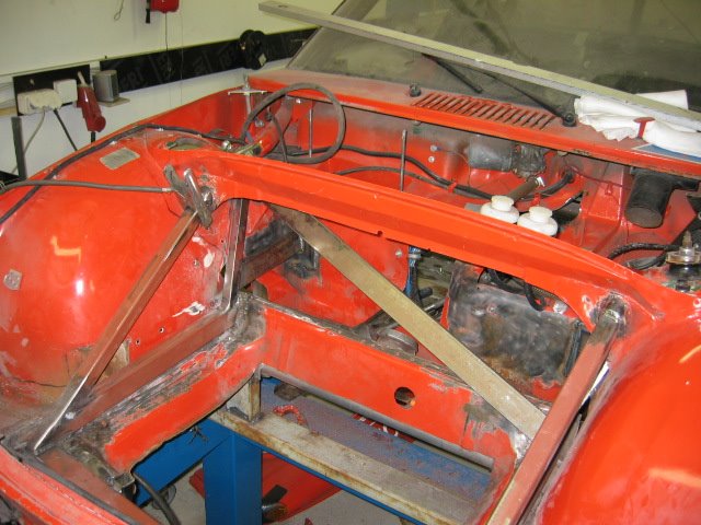
Here is front pictures. Still need to adjust the front with fenders and hood on before welding because it got bended a little while lifting.
I also need to make room for r&p and re route the steering shaft. New pedal box is also under work (if someone needs RSR copy, i have one extra).
Its hard to see from this photo but front was over 30mm angled. 
This one shows the angle problem better even though the gap in this one shows mainly the height modification.
Mika
Posted by: byndbad914 Mar 13 2006, 03:08 PM
Mika,
Hard to tell from the pics but are you running the upper and lower arms parallel at each end?
If not, how are you determining where you are putting your static roll center?
Does it stay above ground through roll front and rear?
How much camber gain are you designing for front and rear? (deg/in or deg/mm is fine as I can convert easily to /in)
I am building a tube chassis car right now and have been beating the crap out of my brain reading Milliken and any other suspension book I can get my hands on to figure out where I want to put roll centers, how much camber gain I want to see on 2" of bump, etc. and was interested in knowing what you are setting yours up at.
Thanks,
Tim
Posted by: Jeroen Mar 13 2006, 05:05 PM
wow! looks pretty complex to get it all to close up again
got any info on the RSR pedal box?
Posted by: slugmika Mar 13 2006, 11:38 PM
Hi guys
Tim, yes upper and lower are parallel. Now it's easy to adjust roll center just by changing the upper arms angle.
I don't remember how much is the camber gain but i'll check that later from my drawings. Front is stock but just raised 2" so camber gain is as per original.
I don't know if you should follow my way because this is my first multilink suspension. I'am sure we need to test this a lot but that happens after 50cm of snow has melted
I'am sick at home so i'll have time to check the camber gain later today.
I'll take some pictures for you Jeroen, later
Mika
Posted by: jonwatts Mar 14 2006, 12:05 AM
You've been sick a lot lately. Take care of youself, man!
Posted by: slugmika Mar 14 2006, 01:19 AM
Yes i'we been sick over 4 months now and fever over 2 moths. Finally yesterday i got a call from my doctor and she had "good" news, i have lung fever. That's good news only because finally we have disease named and medicine which should take care of that
Pedal box pictures are in my blog now.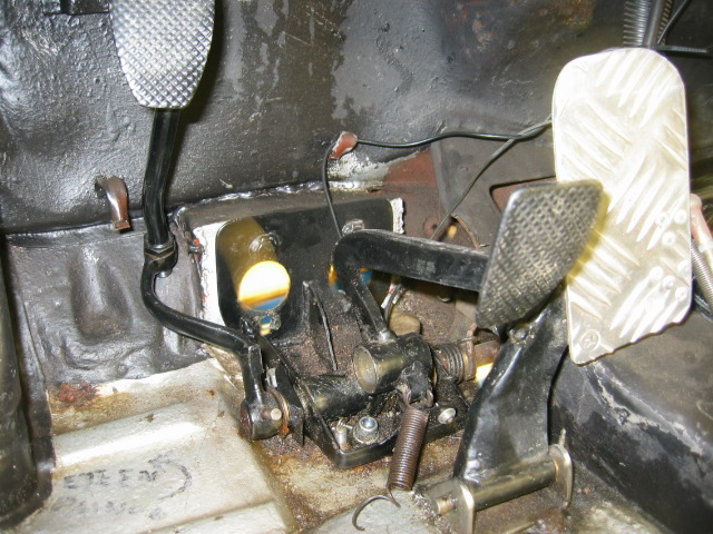
Progress is slow but i will be there when season opens
Just need my new Koni's so i can make the brackets and make needed modifications to tub 
Mika
Posted by: slugmika Mar 27 2006, 04:36 AM
Koni's just arriwed so i started to make brackets for them.
Here is couple of pictures about progress. I <!-- emo&:sawzall: --><!-- endemo --> off the shock towers so i will have
more room to make the brackets.
Suspension is also welded to chassis but it's still attached to table so i can make the new supports for transmission. 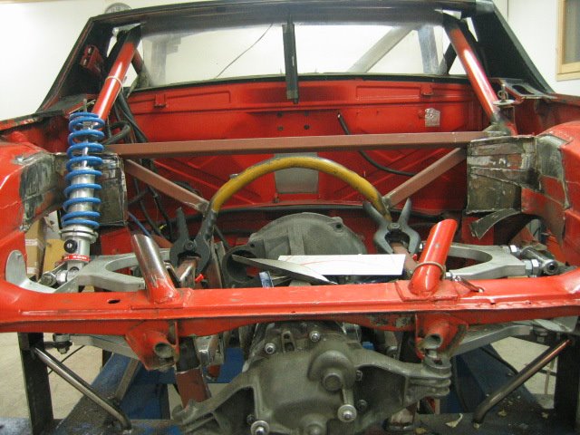
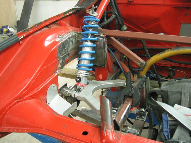
Posted by: slugmika Apr 2 2006, 01:02 PM
Rear is allmost ready. Only thing to do is the shock mounts. 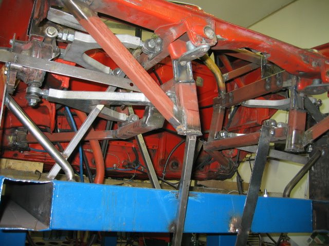
Front frame is also quite ready.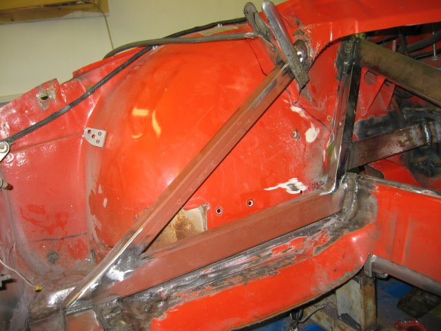
When fenders arrive, i can make new bumper mounts and oil cooler surround.
I started to make the new pedal box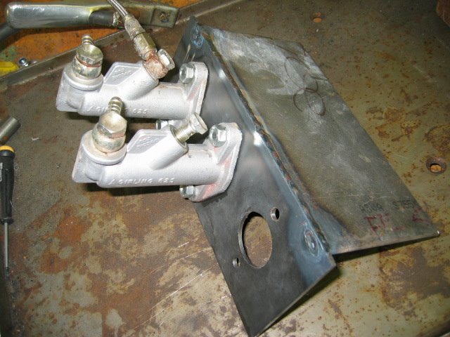
Thats all for today
Mika
Posted by: Aaron Cox Apr 2 2006, 01:08 PM
mika! you are insane!!! looks totally awesome!!!! cant wait to see this bad boy complete!!!
BTW - was this an original finland car?
Posted by: slugmika Apr 2 2006, 01:19 PM
Hi Aaron
Car is imported from Florida to Switzerland and from there to Finland. This car was really rusty. One of the reasons to do this extensive suspension fix was that my car was wrecked and tub was 50mm bendt in front. I think i will need to find better tub to start my full on race car Well, maybe i'll do a Porsche B32 replica first That would be something else for Finnish Roadsport Class.
BTW Aaron, your car looks amazing with the new paint, not that it was ugly before.
Mika
Posted by: Thorshammer Apr 2 2006, 07:12 PM
I am enjoying your project very much. I wish the SCCA would allow us to change these things for production.
I only have one comment, if it is okay, It appears you have just placed the shocks on the rear suspension for the photo purpose, but if they are mounted in that manner, the unsprung mass will increase. If they are mounted with the shock body mounted to the chassis and the shock shaft to the suspension.
Keep up the awesome work, I am looking forward to future pics.
Erik Madsen
Posted by: slugmika Apr 3 2006, 12:55 AM
Thanks for comment Erik.
What would you do? We were thinking about the inline arrangement with pushrod's but thought that we should leave something to do for next winter .
I was going to attach the shock body to suspension and shaft side to chassis, but i can still make it other way if it's wiser.
Btw, do you know how much should i use bumpstop with these Koni's? I figure that it's enough if i just put so much that the shock doesn't bottom?
Mika
Posted by: Thorshammer Apr 3 2006, 08:59 AM
Mika,
With pushrods it over complicates things, unless your packaging will dictate you must have them. As far as Iam concerned pushrods will only be a benefit for two reasons.
- suspension package is in the airstream, and yours really isn't.
-Suspesion package needs to be adjustable with regards to spring/damper progression.
My suggestion on your set up is to mount the shocks with the damper shaft attached to the lower a-arm, not the upper. This will also keep the mass lower in the car. As for the rubber bump stops, they really need to be installed, and I woudl suggest determining the final placement of the upper shock mount after you (maybe you already have) determine what the travel will be and where ride height will be. Then have the bumpers come into play in the last 10% of the travel. This would be my suggestion not knowing exactly what you have.
Erik
Posted by: slugmika Apr 3 2006, 12:05 PM
Erik
Now i understand what you mean. I need to attach the shocks to hub part. Those balljoints are not strong enough to attach shocks to arms. Arms are also designed so that they can't take the powers from shocks.
I'am trying to attach those as low as possible.
Thanks alot for your comments, i really appriciate it.
Mika
Posted by: slugmika Apr 21 2006, 09:11 AM
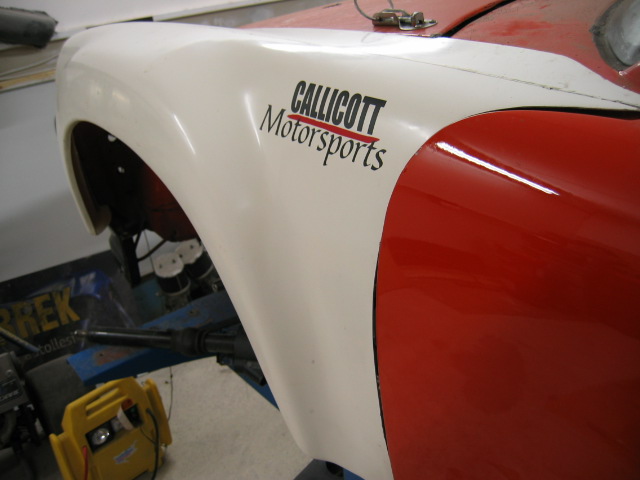
Finally i got the quarters and front fenders, BIIG THANKS DAN!
Next weekend we are going to prep the tub for paint and paint it.
But before paint i still need to weld few spots.
Here is couple pictures of Callicott Motorsports REALLY nice fg parts.
Mika
ps. Dan, i didn't find the "motorsport" font of your logo but i will keep searching. This is the closest one that i had.
Attached image(s)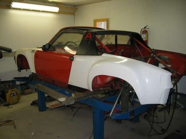
Posted by: Jeroen Apr 21 2006, 11:07 AM
Nice!
Those fronts look a lot better than the ones I got from Rennspeed
Oh and check your mailbox for the font/logo 
Posted by: slugmika Apr 21 2006, 12:46 PM
quality of the parts is suberb 
Jeroen, i can't open or save the logo eps 
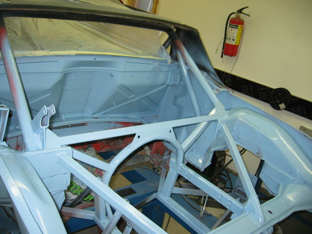
Posted by: slugmika Apr 23 2006, 11:52 AM
It was nice sunny day and +10c so i painted quarters outside.
First coat of blue is on (front is still unpainted)
Next light skim of bondo and final paint.
Engine bay is ready for engine.
Ok, there is some brackets still to be welded and couple of places where the tub is welded to table needs to be painted again.
Jeroen, i got the font and now Callicott Msport logo is ready, thanks.
Attached image(s)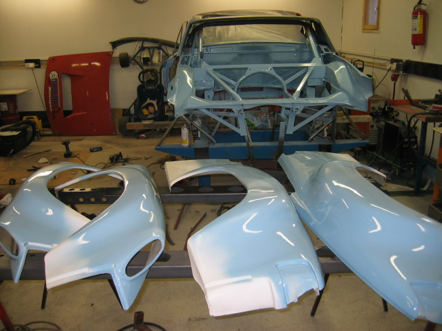
Posted by: Aaron Cox Apr 23 2006, 11:55 AM
its got the blues 
Posted by: slugmika May 2 2006, 03:06 AM
Troubles! Need to make new a-arms. Someone (me) did a slight 80mm mistake when measuring track width (from bearing house to bearing house).
Oh well, the new ones will be made of tube. Front is ready and even the steering shafts are moved to trunks side.
No problem in front with 225-50-16 tires.
Mika
Attached image(s)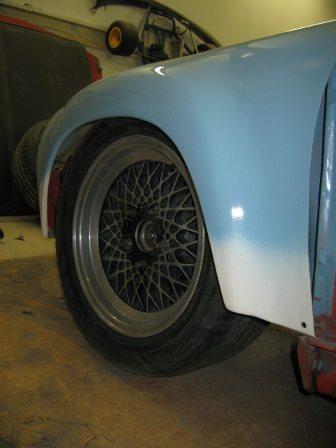
Posted by: grantsfo May 2 2006, 07:17 AM
good color choice
Posted by: slugmika May 18 2006, 05:43 AM
hi again
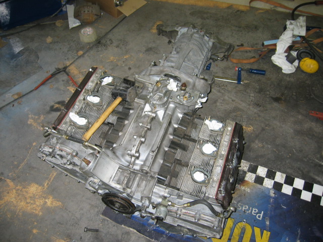
still 1week to first race. engine is finally ready and after trying 8 times it now fits.
car is on its wheels and yesterday we started to rebuilt oil-lines and system.
hopefully we'll test drive the car in weekend.
Attached image(s)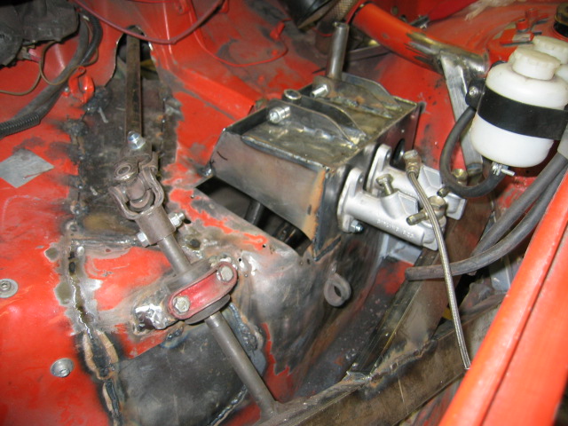
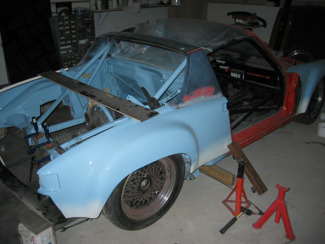
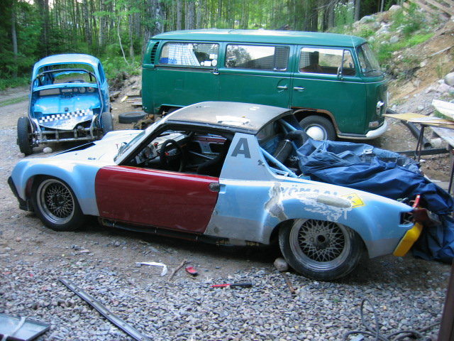
Posted by: slugmika Jun 15 2006, 01:37 PM
Not much interest here I think well call this thread dead, but before that here is some pictures.
Because of lot of things i did not complete my car before first race. Now we have one open class race in next weekend and we are going to give the shakedown in there. We haven't been able to drive in a track at all so it might be stupid to even go Next official race is in 8th of next month but we are going to get a new baby in 6th so i won't be able to go there. There is lot of things that needs to be finished but we'll have the new look ready before Historic Grand Race (thanks again Dan and Jeroen).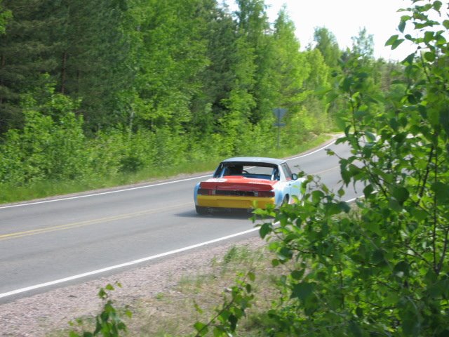
Thanks
Mika
ps. i just parked my future (suby) project to barn.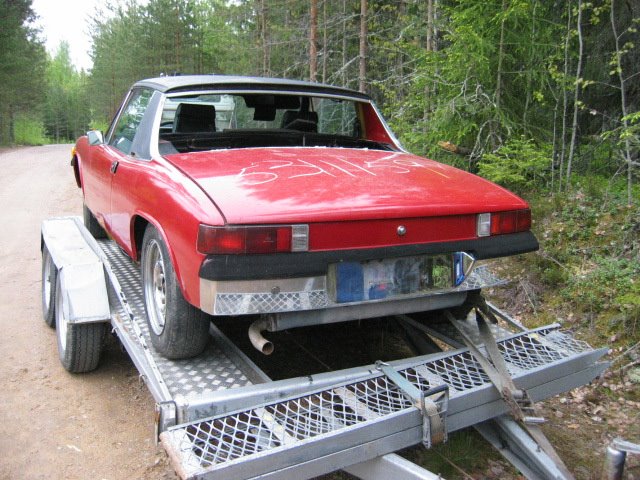
Posted by: Aaron Cox Jun 15 2006, 03:01 PM
OMG!!! the thing is L O W !!!!
hows the new suspension feel?
Posted by: Eric Taylor Jun 15 2006, 03:11 PM
That rear suspension is a work of art! Looks great. What kinda springs or shocks ar you going to put back there?
eric
Posted by: Jeroen Jun 15 2006, 04:52 PM
way to go Mika!
what did you end up using for the front suspension?
you mentioned changes to the a-arms...
details / pics ?
and keep us posted when the new baby is born!
Posted by: slugmika Jun 16 2006, 12:11 AM
Hi guys
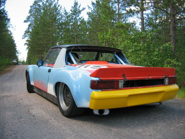
New suspension feels different. Steering response is much much "tighter". Now i can say that it feels like go-cart. Aaron, the front is actually still 2cm too high, rear is in its riding height.
Rear springs are 82kg/cm at the moment. We started to test it with 45kg/cm which is about 250lbs/inch. These springs are the 5th that we tested and these are quite close to final. Shocks are Koni's aluminium ones with double adj.
Front is the one that i used last year. Just raised it 7cm to correct the steering geometry to original porsche specs. 22mm torsion bars and 25mm cromoly sway bar. Front shocks are Spax's from England.
I'll add some pictures later
Mika
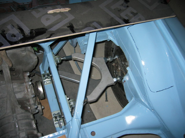
Posted by: slugmika Jun 16 2006, 12:17 AM
Here is better picture of the rear
Attached image(s)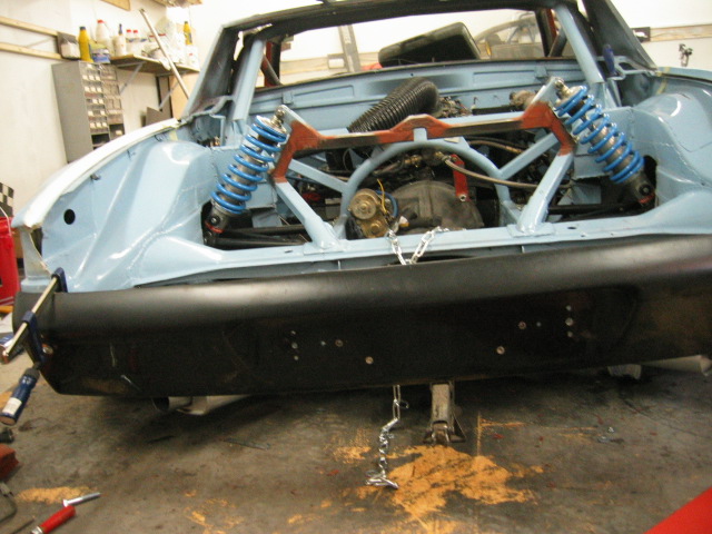
Posted by: Lou W Jun 16 2006, 12:29 AM

Here is better picture of the rear
Wow, that is amazing

You sure did a great job
Posted by: Andyrew Jun 16 2006, 01:00 AM
Amazing work!!!
Andrew
Posted by: slugmika Jun 18 2006, 01:44 PM
Thanks for your kind words 
weekend is over, finally. We had a lot of problems but really good news is that rear suspension works like i planned.
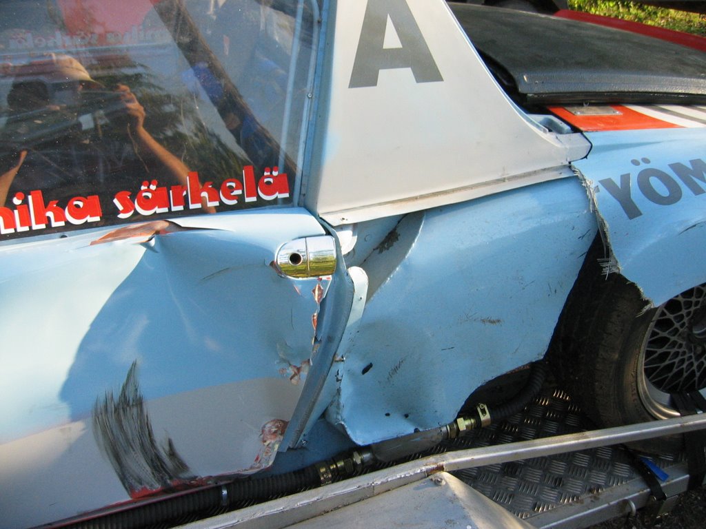
Bad news is that even thought i was taking extra care not to damage my car it got hitted twice by one 928 S.
Here's the result, sorry Dan 
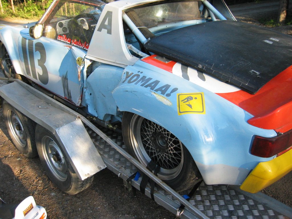
Posted by: slugmika Jun 18 2006, 01:47 PM
Oh, one more thing, i won my first trophy, jiihaa. I was the fastest of the few Roadsports including V8's
Posted by: grasshopper Jun 18 2006, 01:53 PM
damn! that sucks bigtime your suspension is amazing!
Posted by: Jeroen Jun 18 2006, 04:44 PM
damn... what a sorry sight
Posted by: jd74914 Jun 18 2006, 06:24 PM
Mika, the suspension is really impressive.
I think the car is a crash magnet tho
Posted by: slugmika Jun 19 2006, 03:02 AM
Yes, i was wondering that crash magnet thing too. Maybe i'am too low and small? I was starting behind Renault Clio (tiny car) and wasn't able to see starting lights. Door is quite bad and that Callicott Motorsport quarter panel really needs lot of work to get it nice. Oil tank has a hole in it and as you can see, it needs some straightening. Oh well, atleast i get a change to test my new AC/DC Tig.
Mika
Posted by: Aaron Cox Jun 19 2006, 11:10 AM
F A W K!!!
paint a big meatball or target on it! jeez that blows....
hope you can get it sorted out! next time order spare FG parts LOL
Posted by: slugmika Jun 30 2006, 02:57 AM
Thanks to Slits i'am getting my new doors quite soon.
Loaned drivers side door from my "street car" project.
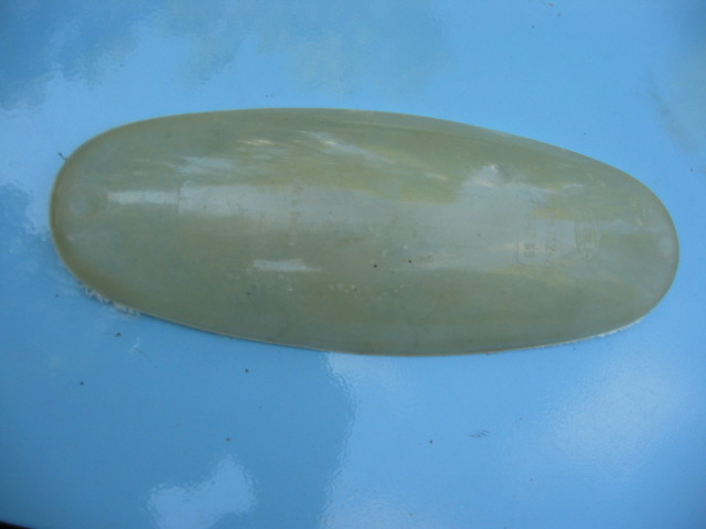
rear quarter is fixed. Transparent areas are fixed. Still need to fix the oil tank and some smaller things. I made a new part also, even the made in germany can be seen.
This time next week we will have baby so i need to work hard.
Mika
Attached image(s)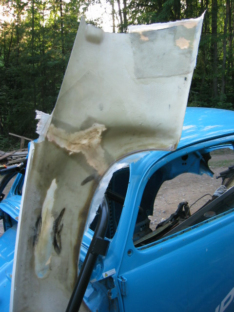
Posted by: kg6dxn May 8 2011, 10:57 AM
This thread needs a ![]()
Any updates?
Posted by: kid914 May 23 2011, 01:55 PM
I had to make it public. That's the only way i'am going to get anything done.
So, i had to convert my rear suspension to multi link, raise the front suspension, built a new pedalbox, rebuilt the engine and tranny, make attachemets for new fg flared rear and front fenders, make a new carbon top, glue the new heated windshield, paint the car and lots of other stuff.
I will post pictures when ever i have any progress.
Here is the starting point
hub's are attached to table
lower part of the new front
i'll put more pictures later
Where did you get your front bumper.
Powered by Invision Power Board (http://www.invisionboard.com)
© Invision Power Services (http://www.invisionpower.com)