Printable Version of Topic
Click here to view this topic in its original format
914World.com _ 914World Garage _ Let there be light
Posted by: smrz914 Jan 8 2006, 02:19 AM
Here are some samples. These are pretty much how they will be. I need to order some more LEDs to complete this trial set. I only had enough to do 1 side of the car. The 914 taillights are on the very left and for comparison I turned on the brake lights on my Integra. the 914 taillights are at the very front of the Integra.
Attached image(s)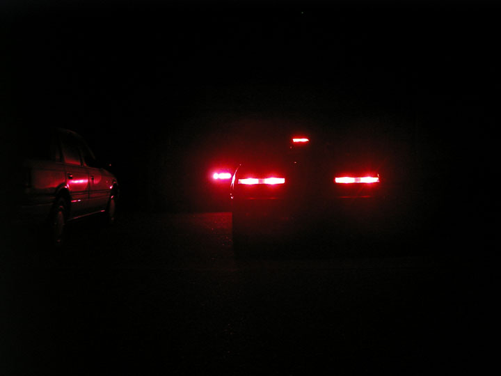
Posted by: smrz914 Jan 8 2006, 02:19 AM
more
Attached image(s)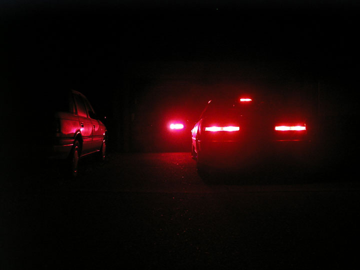
Posted by: smrz914 Jan 8 2006, 02:20 AM
more
Attached image(s)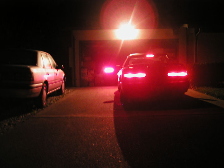
Posted by: smrz914 Jan 8 2006, 02:20 AM
last one for now
Attached image(s)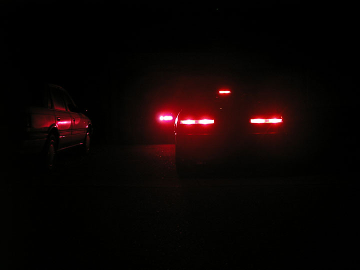
Posted by: smrz914 Jan 8 2006, 02:22 AM
I noticed it's really hard to take pictures of the taillights. The real difference is when you see it in person.
Posted by: neo914-6 Jan 8 2006, 02:35 AM
Hey Paul! How many LED's do you have in an array (per bulb replacement)? My brother-in-law offered to help me put some together for neo914-6 but I found some assemblies for sale on eBay that I may use...
Lookin good! 
Posted by: smrz914 Jan 8 2006, 02:51 AM
30 LEDs for the reverse lights 28 for brake and 28 for blinker. stock bulbs are 21 watts and these use about 3.5 and are a fraction brighter at the same voltage. They are my own design, custom made.
Posted by: Andyrew Jan 8 2006, 03:40 AM
so are you making a kit for this?
Im a waiting for you to finish this. 
Lookin good!
Posted by: bd1308 Jan 8 2006, 09:40 AM
yep i'm all for it....
b
Posted by: McMark Jan 8 2006, 11:45 AM
Great job Paul! I can't wait for them to go into production!
Posted by: dakotaewing Jan 8 2006, 01:05 PM
| QUOTE (smrz914 @ Jan 8 2006, 03:22 AM) |
| I noticed it's really hard to take pictures of the taillights. The real difference is when you see it in person. |
Paul -
The problem is you are taking these pics at night -
If you want to get a very good representation, you will need to do these at twilight, when the exposure for ambient light, and the exposure for the taillights are closer together -
Start right at sundown, and shoot until its dark - Make sure you mount the camera on a tripod, and make sure the flash is off, or at least off half the time you are shooting -
(I would'nt recomend have tha flash on at all...)
Make sure the cars are not in direct sunlight when you start...
You will need to take pictures during a 30 minute window, and will find that the best exposures, are during a 6-8 minute window during that timeframe...
Hope this helps -
Thom
Posted by: TonyAKAVW Jan 8 2006, 01:27 PM
| QUOTE |
| 30 LEDs for the reverse lights 28 for brake and 28 for blinker. stock bulbs are 21 watts and these use about 3.5 and are a fraction brighter at the same voltage. They are my own design, custom made. |
Wow! Are you using the SuperFlux/Pirhana LEDs? 28 of those would be unbelievably bright. I built a pair of 16 LED arrays that I will eventually use, using the superflux LEDs and they hurt the eyes to look at.
-Tony
Posted by: Brando Jan 8 2006, 02:49 PM
How would these compare with the ones from SuperBrightLEDs.com? I got a set I've been unwilling to install because they don't let the flasher unit do it's flashing.
Posted by: smrz914 Jan 8 2006, 04:46 PM
Andyrew- Yes these will be a kit hopefully sooner then later. I ordered a set of 4 test production PCBs to test the circuit and to see how it fits in the car. For now there will only be a US taillight version. Soon after I get orders for the US version and see that people like them I'll start making Euro versions. That should be a pretty easy change. Then after I pay for school and cover my other costs I'll start on making an upgrade for the front blinkers. Then I'll think about doing a lite race version. 
dakotaewing- Thanks! I'll try that out. I'll post some pictures that my roommate (good with cameras) helped me take.
TonyAKAVW- these are SuperFlux LEDs
Brando- My LEDs are at 10,000mcd and the ones that superbrightLEDs are a 2500mcd now I don't know if they are comparing apples to apples. But I know for sure that mine can run at a max forward current of 70mA and theirs run at a max of 40mA the viewing angle looks the same. Mine are bright and will hurt your eyes. I don't run them at full current for that reason and for some flexability in voltage changes.
The flasher unit depends on current draw to do the switching. Your LEDs probably won't draw enough current to make the flasher work properly. It my kit needs the flasher you can get a solid state flasher to fix that problem.
Attached image(s)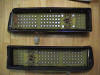
Posted by: smrz914 Jan 8 2006, 04:49 PM
If you are interested in these be warned that you will need to cut part of the housing to fit the boards inside.
Posted by: ChrisNPDrider Jan 9 2006, 12:17 PM
Sweet! I've been waiting for the LED light posts to re-surface. I drive my 914 daily and even after 2 months am still nervous about other people hitting me from any direction....I was actually in a rear-ender in my '92 Volvo 2 months ago due to slow-downs on hwy 80. I REALLY WANT THESE LIGHTS ASAP, and then LED interior light, LED 3rd brake light... 
As a fellow DIYer, of course because I have a 914, I am interested in helping out on your project if needed to speed things up. PM me if interested....Sounds like you've done most of the fitting work and sourced the best part. Maybe delegating some of the busy work (cutting, soldiering) would give you more time for R&D and school?

Posted by: bd1308 Jan 9 2006, 12:54 PM
I could do some soldering...maybe a kit is in order, for those of us who can do the dirty work....you can do R&D.
b
Posted by: Mueller Jan 9 2006, 12:56 PM
nice job....
any chance of a sequential signal kit? 
Attached image(s)
Posted by: TonyAKAVW Jan 9 2006, 01:01 PM
How's the turn signal flasher work? When I put LEDs in my car, they didn't draw enough current for the flasher to work properly. I had to build an electronic flasher circuit to replace it.
-Tony
Posted by: bd1308 Jan 9 2006, 01:02 PM
| QUOTE (TonyAKAVW @ Jan 9 2006, 01:01 PM) |
| How's the turn signal flasher work? When I put LEDs in my car, they didn't draw enough current for the flasher to work properly. I had to build an electronic flasher circuit to replace it. -Tony |
resistor?
Posted by: Brando Jan 9 2006, 01:57 PM
| QUOTE (bd1308 @ Jan 9 2006, 11:02 AM) | ||
resistor? |
Yes.
Posted by: TonyAKAVW Jan 9 2006, 02:08 PM
But he claims these consume 3.5 watts versus 21.... So to get the flasher to work you throw away the power savings and you need 17.5 watts worth of resistor... Thats going to be a rather hot/large resistor.
-Tony
Posted by: lapuwali Jan 9 2006, 03:08 PM
The resistor the SuperbrightLED people show looks like it's at least 10W.
There are cheap electronic flasher modules at most FLAPs, which *should* work with LED turn signals. If they don't, then a circuit to make LEDs flash could be assembled for under $10.
Posted by: TonyAKAVW Jan 9 2006, 04:13 PM
| QUOTE |
| There are cheap electronic flasher modules at most FLAPs, which *should* work with LED turn signals. If they don't, then a circuit to make LEDs flash could be assembled for under $10. |
I actually tried the FLAPS turn signal flasher, for some reason I couldn't get it to work right.
I built a circuit but it cost a bit more than $10... The problem is that in the stock setup, when you engage the flasher, the resistance of the bulbs results in heating of a bimetal strip inside the flasher. So the flasher and bulbs become a single oscillating circuit when the turn signal switch is engaged.
My solution was to build a circuit that is constantly "flashing." I used a 555 timer IC and a potentiometer for flash rate control. The switching device was a P-channel FET. These are required because you are switching the +12, not the ground. P-channel power FETs are a bit hard to come by. They are out there, but not too common. A relay would work, but because the circuit is always flashing, the relay would eventually wear out not to mention make an annoying noise.
-Tony
Posted by: Porcharu Jan 9 2006, 04:21 PM
You need the "heavy duty" flasher from a FLAPs. These don't care what the load is. They might be listed under trailer towing stuff. This type of flasher uses a mechanical or electronic dodad to flash the lights that is not related to current draw. The mechanical ones have a really nice solid "click" to them when they operate. I used one of these on my old Mustang that was a bit on the loud side so I could hear the blinkers blink when I left them on - no cancelers on that car.
Steve
Posted by: lapuwali Jan 9 2006, 05:20 PM
| QUOTE (TonyAKAVW @ Jan 9 2006, 02:13 PM) | ||
I actually tried the FLAPS turn signal flasher, for some reason I couldn't get it to work right. I built a circuit but it cost a bit more than $10... The problem is that in the stock setup, when you engage the flasher, the resistance of the bulbs results in heating of a bimetal strip inside the flasher. So the flasher and bulbs become a single oscillating circuit when the turn signal switch is engaged. My solution was to build a circuit that is constantly "flashing." I used a 555 timer IC and a potentiometer for flash rate control. The switching device was a P-channel FET. These are required because you are switching the +12, not the ground. P-channel power FETs are a bit hard to come by. They are out there, but not too common. A relay would work, but because the circuit is always flashing, the relay would eventually wear out not to mention make an annoying noise. -Tony |
I can't easily make circuit diagrams from here:
B+ to 555
555 to chassis ground
pot to 555 for timing adjustment
555 "flash now" out to relay switch in.
relay switch "ground" to 10K ohm resistor to relay power output
relay power in to B+
relay power out to turn signal switch.
Now, the relay won't operate until the turn signal switch engages at least one light. Tie the indicator bulb to the relay power out, as well, and tie the other end to ground. You'll lose the "no flash" or "slow flash" when a bulb burns out, but that should be a very rare event with LED "bulbs", anyway.
Posted by: smrz914 Jan 10 2006, 09:01 PM
I'm glad you guys like what you see so far.
| QUOTE |
| nice job.... any chance of a sequential signal kit? |
Sequential is possible but right now I need to see how this stuff sells before I move on.
| QUOTE |
| How's the turn signal flasher work? When I put LEDs in my car, they didn't draw enough current for the flasher to work properly. I had to build an electronic flasher circuit to replace it. |
This new set hasn't been tried in a car yet. I hope that It will be on a car before I leave for school. So that leaves me with a week and a half.
As for the flasher SuperBrightLEDs.com has a flasher http://www.superbrightleds.com/tail-brake-turn.html. I'll order this one to try if it is necessary unless someone wants to try one out and tell me if it works or not.
If you order check the pinouts to see if they will work in our cars and post the results. thanks
Powered by Invision Power Board (http://www.invisionboard.com)
© Invision Power Services (http://www.invisionpower.com)