Printable Version of Topic
Click here to view this topic in its original format
914World.com _ 914World Garage _ Paging Mueller
Posted by: r_towle Jan 11 2006, 08:07 PM
Hi guys,
Through a local DOD contractor I found a few small shops that will make Berillium Diaphrams...
Apparently the new fighter jets use alot of the material, so they are set up to work with it, and do small runs...
So , what I need, to get a price, is CAD drawings of the diaphram, and the piece that gets pressed into the middle..
I have been told that they can do it, based upon my description.
So, did anyone ever make a drawing of the diaphram...or maybe please......mike...could you...
Rich
Posted by: Jeff Bowlsby Jan 11 2006, 09:41 PM
Cool....!
Mike, you are the man to do a drawing. I could do a hand-drafted drawing if needed.
I hope this works out, it would save a lot of D-Jet systems.
Posted by: Demick Jan 11 2006, 09:51 PM
Jeff
If you have a diaphragm lying around that you can get over to me, I'll make a 3D CAD model and some detailed engineering drawings of it.
Demick
Posted by: jimkelly Jan 11 2006, 10:07 PM
do they really need a cad drawing or can they work with an actual part?
did they quote you a ballaprk price range?
if you can't get anyone to do a cad - I can send you a bad mps.
Jim
Posted by: r_towle Jan 11 2006, 10:09 PM
cad.
if they need to measure, and make the drawing...that takes time.
rich
Posted by: rick 918-S Jan 11 2006, 11:13 PM
Dude! 
Posted by: Bleyseng Jan 11 2006, 11:37 PM
I have a spare decent diaphram laying around if you need one. Ray Greenwood is working on making some but I am not sure about the center pieces fitting.
Posted by: Demick Jan 12 2006, 09:44 AM
Jeff is going to send me a diaphragm. After I get it in CAD, I'll make the files and drawings available.
Demick
Posted by: Bleyseng Jan 12 2006, 09:56 AM
Is it Berillium? The ones I have are copper or atleast mostly copper. Now the aneroid cells are something different.....
Attached image(s)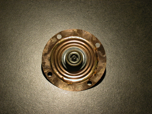
Posted by: ppickerell Jan 12 2006, 10:01 AM
I can make the beryllium piece in my shop, but there will be form tooling required to make the concentric rings.
Posted by: r_towle Jan 12 2006, 10:27 AM
I was just going on what you guy have been saying for years...
I read lots of threads here...I was told the original diaphram (the one that breaks) was made from berillium.
The replacements that were being used were made of a copper bronze alloy that did not work the same way and were harder to tune.
So, I ran into this guy, and I am willing to take this through to a price etc...
And yes, they would make a press tool for the ridges, and they would make new center pieces, and assemble the whole deal...at least that was the concept.
At least we can have a healthy discussion and possibly they may have some setup ideas...
I would prefer we make these entirely new, no need to hunt down cores just for the middle part,,,then have to disassemble them...
Rich
Posted by: Jeroen Jan 12 2006, 10:37 AM
funny, I've been looking into the same thing
was doing some investigating on the issue, but because of being too busy, I got a little side-tracked
lets see what you can come up with...
Posted by: Jenny Jan 12 2006, 10:57 AM

I thought you guys were talking about these things!
Jen
Posted by: Jenny Jan 12 2006, 11:00 AM
bugger... the picture didn't take.
Attached image(s)
Posted by: airsix Jan 12 2006, 12:11 PM
| QUOTE (r_towle @ Jan 12 2006, 08:27 AM) |
| I was just going on what you guy have been saying for years... I read lots of threads here...I was told the original diaphram (the one that breaks) was made from berillium. The replacements that were being used were made of a copper bronze alloy that did not work the same way and were harder to tune. |
Copper and Copper-bronze will work harden. Beryllium won't. It's also over 30% more elastic than steel..... however it's NASTY stuff. If any of you DO decide to work with it be aware that absorbsion of airborne particles is a VERY serious health risk. :deadsmiley:
IMHO it's more likely that the diaphrams were made from Beryllium copper rather than pure Beryllium. Beryllium copper is 98% copper 2% beryllium.
B.C. is highly ductile which makes it great for forming complex stamped parts (see picture above) It's also the only copper alloy I know of that can be heat-treated. It is used for springs and such in specialized applications (it's light, doesn't work harden easily, and is a good electrical conductor).
-Ben M.
Posted by: Demick Jan 12 2006, 01:22 PM
Yep. I would guess that the appropriate callout for this would be half-hard BeCu.
Demick
Posted by: r_towle Jan 12 2006, 01:41 PM
ok, you sound smart...
can you arrange to have someone test the original diaphram to determine what it is?
At least if we start with the correct alloy we will be better off...
Rich
Posted by: Demick Jan 12 2006, 06:31 PM
Im not sure how to have it tested, but BeCu is the natural choice for this application. Not many materials suited to this. Only question in my mind is the degree of hardening.
Demick
Posted by: TimT Jan 12 2006, 06:41 PM
You will have to sacrifice one and send it to a Materials Testing Lab and have an assay done.
Since we know kind of what it is made of makes it much easier for the lab, and sort of less costly for us.
Posted by: Bleyseng Jan 12 2006, 07:02 PM
I can send someone dead OEM ones.....got a few of those sitting around in a box along with 50 dead mps's.
Posted by: Jeff Bowlsby Jan 12 2006, 08:10 PM
If I recall, Brad anders posted a series of patents for the MPS on his website...the material was specified there...but don't trust my memory without verifying it.
Posted by: r_towle Jan 12 2006, 09:23 PM
ok..
So Demick will get a CAD drawing done...
Bolwsby will look up the material name...
If not, can airsix help us get the material propoerly tested?
Geoff will donate old material for testing...
I will get the drawings to the engineering firms and get a price/size of the run...
I am told that we can work with at least three companies that are all set up to do this...
Demick, is there a standard CAD file type....(Im thinking similar to ascii text, or gcode) that can be given to multiple companies...so they can read it with whatever software they happen to have???
Or is Autodesk a standard...know what I mean here...
Posted by: Demick Jan 12 2006, 10:19 PM
I will do the CAD models in Solidworks. I can output most any format that shops can import. Most likely, they will prefer a 3d IGES or STEP file. They can also simply work straight from the drawings I will create and skip the CAD models if they choose.
I've read the patent documents. I have them at work and can take a look at the material - but extremely unlikely that it will actually have a useable material callout and hardness.
I believe that heat treatment is done after forming. So we have the option to have some diaphragms made and then heat treated differently. 1/4 hard, 1/2 hard, 3/4 hard. They we can make a simple fixture to pull a vacuum on the different diaphragms and compare them to stock to see which one most closely matches the stock movement.
Be sure that we include Patrick in this. He has a great shop and does great work and is an honest guy (as well as a 914 guy). He knows what he is doing and will give us the lowdown without any BS as far as the mfg and tooling of this.
Demick
Posted by: r_towle Jan 12 2006, 10:21 PM
Im all for Patrick doing it...
I just want a solution available...
Rich
Posted by: Demick Jan 12 2006, 10:34 PM
| QUOTE (r_towle @ Jan 12 2006, 08:23 PM) |
| I will get the drawings to the engineering firms and get a price/size of the run... |
I'm all for this, but I think this will be the stumbling block. My guess is that price for tooling + the first 50 parts will be in the $5000+ range.
So you'll need to find someone to front this money, and then you'll have to then find 50 people to buy them for $100 each (and this still doesn't include the rebuilding of the MPS to install the new diaphragm). And that is all just to break even.
Anyway, this is just my estimate of the situation. Once quotes are in, then you can evaluate if it is worthwhile and where the $$ will come from.
Demick
Posted by: r_towle Jan 12 2006, 10:40 PM
you may very well be right on the price, but I would like to get that real information out on this board...
I am confident that we can put a real world number here, not a ballpark.
If it is truely cost prohibitive, it will make the decision regarding saving the FI pretty simple...
Eventually, all the used MPS's that are out there will be gone...
So, either we find a cost effective way to do this, or we change our cars...
I personally would prefer to solve this problem..
If we find out that the alloy is not berrilium, that would reduce the price, because it will increase the number of companies that could do the work..
So, I think we need both answers, how much to make this part, and what the actual material is..
Rich
Posted by: SLITS Jan 13 2006, 12:37 AM
| QUOTE (Demick @ Jan 12 2006, 09:34 PM) | ||
I'm all for this, but I think this will be the stumbling block. My guess is that price for tooling + the first 50 parts will be in the $5000+ range. So you'll need to find someone to front this money, and then you'll have to then find 50 people to buy them for $100 each (and this still doesn't include the rebuilding of the MPS to install the new diaphragm). And that is all just to break even. Anyway, this is just my estimate of the situation. Once quotes are in, then you can evaluate if it is worthwhile and where the $$ will come from. Demick |
Your estimate was about 5K cheaper than I thought...I was trying to get a contact in China to make them...but the funding issue killed that idea.......
Posted by: Bleyseng Jan 13 2006, 09:17 AM
Let's just break into Brett Inst. and steal their stash of diaphrams!
Where is Miles when you need a good plan!
Posted by: Demick Jan 13 2006, 09:38 AM
| QUOTE |
Your estimate was about 5K cheaper than I thought...I was trying to get a contact in China to make them...but the funding issue killed that idea....... |
Here's what I wrote sometime last year on the subject:
| QUOTE |
The material for the diaphragms is most likely beryllium copper (BeCu). Not really exotic, but is environmentally hazardous to process. Companies like Laird buy it by the ton to make EMI gaskets out of. The material is not really the problem - it is the cost of the tooling to have the correct shape for the diaphragm stamped out. Then the low volume once you've got the tooling paid for. It really all comes down to money. Figure $2K for tooling, and then around $50 each to buy them in low quantities like 25/batch. Then you've still got to have the center boss machined and pressed into the diaphragm - a little more in tooling to create the tools that will press and flare the boss into place. So figure a cost of $100 each for a complete diaphragm. Then you've got the labor to rebuld the MPS, some extra profit to pay off tooling. It all adds up. Hard to justify when you can still get used MPS's for $100 or less (last ones I bought were $15 each at a swap meet). |
This is all even harder to justify when you can buy a Brett Instruments rebuilt unit for just over $200. Some people have complained that the Brett diaphragms are the wrong material and don't have the right response. But my opinon is that the diaphragm response is not all that critical. Sure, it need to be close, but not exact since it only provides the transition from part load to full load enrichment. It's the aneroid cells that are most important in their response and how they expand - not the diaphragm.
Demick
Posted by: Bleyseng Jan 13 2006, 10:33 AM
| QUOTE (Demick @ Jan 13 2006, 07:38 AM) | ||||
Here's what I wrote sometime last year on the subject:
This is all even harder to justify when you can buy a Brett Instruments rebuilt unit for just over $200. Some people have complained that the Brett diaphragms are the wrong material and don't have the right response. But my opinon is that the diaphragm response is not all that critical. Sure, it need to be close, but not exact since it only provides the transition from part load to full load enrichment. It's the aneroid cells that are most important in their response and how they expand - not the diaphragm. Demick |
I disagree......crappy stiff diaphrams make the mps transition response shitty or worse a off/no type. Aneroid cells in for altitude differences I thought although early type 3 MPS don't even have a diaphram!
Posted by: r_towle Jan 13 2006, 11:05 AM
so, did someone send the diaphram to Demick to get a drawing produced?
I would like a real price from a real shop (one that handles this material)
We need to get a celar idea what the material is also.
Rich
Posted by: redshift Jan 13 2006, 11:17 AM
| QUOTE (Bleyseng @ Jan 13 2006, 11:17 AM) |
| Let's just break into Brett Inst. and steal their stash of diaphrams! Where is Miles when you need a good plan! |
Probation.

M
Posted by: kwales Jan 13 2006, 12:29 PM
Copper sheet would prolly be too soft. Berrylium copper is a spring and can be obtained in various thicknesses and tempers. (full hard, half hard, quarter hard).
I've designed parts using the stuff so I prolly have design info in a box in the basement- somewhere.
Stuff is EXTREMELY TOXIC if ground. Makes a lotta places not want to deal with it.
Anyhoo, stuff aint that hard to emboss features in. Made embossed parts once with little "V"s. Was told it couldn't be done. Off I went. Little fixture, coupla crude dies, wham, bam and workable parts.
Looking at Brad's page, the diaphragm has addressed the same problems I ran into. One, berrylium copper doesn't like to stretch too much without cracking. Two, radii in the embossing areas is critical to good parts, and three, it can be done.
Done a lotta progressive die sheet metal parts and this thing is cake to do - once the dimensions are obtained. Worked with Mr. Brunk (Brunk tooling) a buncha times making formed titanium parts. He was a master die maker from the old school and made unbelievable things with simple dies or from a progressive die line. (steel strip into machine, formed parts on a retainer strip out).
Anywhoo, you need a hardened form die to emboss the plates and a cut die to cut the diameter and punch the holes simultaneously. The hole die can be done easily with EDM wire. The form die has to be machined or ram EDM'd. (burned).
If the dies are right, then the parts could be made repeatably and relaibly. Put a sheet into the form die, and whack it with a BF hammer to form the embossing. More than one whack is ok as the dies prevent overforming the material. Remove from the form die, place in the punch die and whack with a BF Hammer.
Voila, instant part.
So, what to do?
1. Anybody have access to a rockwell hardness tester? Need to find out temper of material
2. Anybody have aloose part and a micrometer? Measure raw material stock thickness away from embossed (stretched) areas- prolly at rim is best.
3. Anybody have access to an optical measuring system? Laser or comparitor. A simple comparitor with XY readouts and a cross sectional slice of the part can do it. Need to pot the diaphragm in clear epoxy so the cut and grind won't distort the part.
Guess what we really need is an engineer with lunchtime access to a company materials lab to get the temper and dimensional info.
Ken
Posted by: Jeff Bowlsby Jan 13 2006, 02:18 PM
1 perfect diaphragm shipped to Demick. It may be worth considering to reuse original inner and outer screws to minimize the cost. These are generally in excellent condition and would only add to the cost if reproduced.
Let me know if you need anything Demick. If the price is right I'd buy in quantity.

Posted by: r_towle Jan 13 2006, 02:23 PM
I think that re-using these parts may make it to difficult...
Although, if you devise a process to press the inner fitting in place, then we just need to raw diaphram with the correct size hole....
That would be alot less costly...
Rich
Posted by: Jeff Bowlsby Jan 13 2006, 02:33 PM
There is the diaphragm with a female threaded fixture pressed into it. I know where to obtain the press-on rings for the fixture, but a new fixture would need to be milled and that assembly completed. This is the essential assembly we need as a minimum.
The original inner and outer screws which thread into the fixture are what I am suggesting can be reused. The inner screw looks like some kind of chromium steel with a specially milled 'mushroom' shape where it bears onto the aneroid cell. The outer screw has both inner and outer threads, its a double threaded tube essentially. Both would be costly to fabricate and unnecessary IMHO.
I wish I had a photo it would be immediately clear.
Posted by: r_towle Jan 13 2006, 02:43 PM
I got it.
So, lets say hypothetically we get two or three parts made..
Part one is the diaphram, with the correct ridges, and the correct hole
Part two is the fitting (for lack of a better term) that goes into the middle and it is threaded for the outer screw...
Or part two/three is a two piece fitting that can be pressed together from both top and bottom into the diaphram...
The actual installation of the fitting could be done by one of us, versus a shop...If we design it to be that way.
The screws, I agree can be re-used.
Rich
Posted by: Jeff Bowlsby Jan 13 2006, 02:50 PM
Yep thats it. The center fixture (its about a 1/2" OD cylinder with a flange on one end) is simply inserted through the diaphragm center hole, press-fit and contained onto the diaphram with a press-on ring. 2 new custom parts should do it, the ring is off the shelf.
Posted by: Demick Jan 13 2006, 02:54 PM
Pics from Brad Anders web site.
First, the diaphragm with inner and outer screws: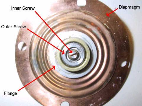
And here is the inner screw: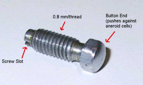
And here is the outer screw: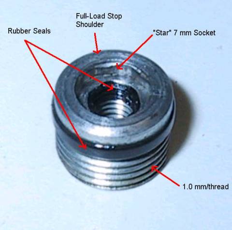
Posted by: r_towle Jan 13 2006, 03:19 PM
Jeff, or Geoff,
Have you guys ever taken one completely apart...
Can the middle section be removed...
I think we need to do this to obtain the correct dimensions for the inner part (s) and the hole in the middle...if we guess, it may not behave the same way.
Rich
Posted by: Bartlett 914 Jan 13 2006, 03:30 PM
The last part looks like it could be made by modifing a set screw. What are the ID and OD diameters?
I can measure the diaphram in vickers if wanted. We use vickers for measuring the hardness of copper cylinders used in printing. I would need an old diaphram for that.
Mark
Posted by: kwales Jan 13 2006, 05:21 PM
There is usually a conversion chart or equation for these testers so Vickers shouldn't be a problem.
Is the copper you test hard or soft?
Ken
Posted by: Bleyseng Jan 13 2006, 09:07 PM
I don't see how the center part can be taken apart but I'll try tomorrow at the shop. I have NO tools here at home tonight. Actually, I have a extra small screwdriver that I just stabbed myself with trying to pry it apart. 
Posted by: r_towle Jan 13 2006, 09:11 PM
I will try tommorow also....it didnt grow like that, so it has to be able to come apart....
Rich
Posted by: Bleyseng Jan 13 2006, 09:13 PM
yeah, witha BFH and a drift! 
I was over at the shop after work today but I can get internet when the neighbors turn on their wireless so I can steal it!
Posted by: Jeff Bowlsby Jan 13 2006, 09:24 PM
The center fixture and pressure ring do not come apart. I tried to cut the ring off with a dremel, no worky. Tried to separate them with a chisel...ruined the chisel.
Don't bother, they need to be fabbed new.
Trust me on this one. 
Posted by: Bleyseng Jan 13 2006, 10:56 PM
I am going to cut one apart in the morning with a metal chopsaw for fun. They look like they are pressed together with a 20 ton press....
Posted by: Bleyseng Jan 14 2006, 06:07 PM
Here is a diaphram cut apart.....damn, I don't see how you can take it apart nor how its put together. Stamped with a press I guess....
Attached image(s)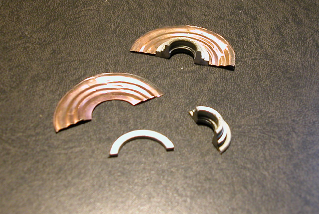
Posted by: r_towle Jan 14 2006, 09:07 PM
Take a few close ups please...
Side view, I cant see it the way you took the pics...
Rich
Posted by: Bleyseng Jan 14 2006, 11:17 PM
Here's another...
The "C" shaped clip is pressed on and then the assembly is stamped to lock it in place. There is no way I can see to reuse these parts.
Attached image(s)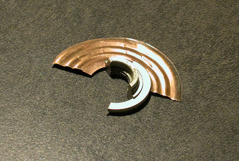
Posted by: r_towle Jan 14 2006, 11:28 PM
personally I am not thinking of re-use...
I guess we would need to build it similar to have the same weight/ flex properties, and a vacuum seal....
We could make one piece and solder the diaphram onto it...
Or we could make two pieces that are threaded together..little bit of silicone to ensure a tight seal...
Please measure the inside dimension of the hole in the diaphram so we have that number...
Rich
Posted by: Bleyseng Jan 14 2006, 11:55 PM
Tomorrow I will as its across town to the shop
Posted by: Bartlett 914 Jan 15 2006, 11:38 AM
[QUOTE]There is usually a conversion chart or equation for these testers so Vickers shouldn't be a problem.
Is the copper you test hard or soft?
The Copper we use is in the 200 250 vicker range. The instrument I use is a Leitz Durimet with a Mini Load Hardenss tester.
I don't know how this metal will harden compared to copper. In copper, you soften it by heating then quickly cooling which is the opposite of steel. To harden, I imagine heating to a spefic temperature temperature and cooling at a some determined slow rate.
As for measuring the deflection, I would make a mounting fixture and measuring the deflection with a dial indicator with a weight applied. I would also do this with 3 different weights to insure the amount of deflection throught the full range is correct.
Mark
Posted by: r_towle Jan 15 2006, 02:25 PM
Cool,
would you volunteer to test the diaphram for hardness.
Rich
Posted by: Bartlett 914 Jan 15 2006, 08:05 PM
[QUOTE] Cool,
would you volunteer to test the diaphram for hardness.
No problem. PM me and I will give you an address. I would be willing to help or make a test fixture for measuring the deflection. I would need a good one for a reference. I would return this undamaged.
Mark
Posted by: Bleyseng Jan 15 2006, 09:20 PM
I can supply a good diaphram and a junk one (pieces) for testing.
Addy??
Posted by: r_towle Jan 16 2006, 01:20 PM
Progress...I love progress..
So, we have a drawing under way...Geoff, please post the inner diameter of the hole in the diaphram...
And we have a hardness test going on...
Now, how do we verify the actual material...
Correct me if I am wrong...the patent documents do not declare the material???
Does anyone have any contacts at Bosch we could ask for a clear answer??
Oh, and on the inner screw retention part,,,I propose a two piece deal, it could be designed to be a threaded piece that gets screwed through the diaphram..
It would make assembly easier..
We just need to design the piece to be the same shape/material as the original to ensure we have the same reaction properties in the new assembly...
Did that make any sense at all?
Rich
Posted by: Bleyseng Jan 16 2006, 08:12 PM

Posted by: kwales Jan 16 2006, 09:55 PM
It's an effin spring...
So you need:
1. Material-
2. Material Thickness- makes a big difference on rate
3. Similar diaphragm dimensions
4. Heat treat for durability-forming issues.
For a quick and dirty material properties calc, cut a strip, measure the width, and thickness. Clamp in a vise and Measure the distance from the wall to the point where the force will be applied. Add weight or force and measure the deflection.
Calculate the modulus of elasticity and look up material.
Use the cantilever deflection equation to calculate the modulus...
deflection= load*length^3 (cubed)/
3* modulus* width *(height^3 (cubed)/12)
There ya go... Won't be exact but I bet it will get you within 85% of the correct value.
Posted by: Demick Jan 17 2006, 10:45 PM
OK. I got the diaphragm from Jeff today. This is the first one I have seen (except for in pictures). I was very surprised at how small the stamped pleates are in this diaphragm. They seem much smaller than they seem from other pictures. Especially the outermost (widest) pleat. It's probably only 3 or 4 mils tall, and is barely even discernable as a pleat.
Attached image(s)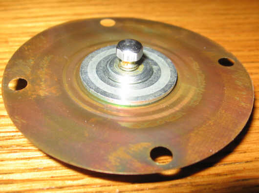
Posted by: Demick Jan 17 2006, 10:47 PM
compared to the pics from Brad Anders' site:
His seem much larger and more pronounced. But maybe it's just the lighting.
Demick
Posted by: Bleyseng Jan 17 2006, 11:12 PM
No, I have seen two styles or that one is a replacement one. The one in the BA pic is from a OEM unmolested unit.
I checked the outer screws size and its a 12mmx1.00thread pitch. Very fine threads
Posted by: r_towle Jan 25 2006, 09:08 PM
so, where are we with this project?
Do we have a drawing yet?
Do we know the hardness of the material in question?
I talked to the berilium guy today and he can do it, but its all talk till he sees a drawing...better than my hand scetch 
Rich
Posted by: RustyWa Feb 20 2006, 02:10 PM
| QUOTE (r_towle @ Jan 16 2006, 12:20 PM) |
| Now, how do we verify the actual material... Correct me if I am wrong...the patent documents do not declare the material??? Does anyone have any contacts at Bosch we could ask for a clear answer?? |
I more than likely can do the material composition test of the diaphram if it is still needed.
Where I work, we have a Niton Alloy Analyzer, which is a non-destructive, hand-held tester for alloy materials. It'll actually tell you the chemical composition of any alloy it tests.
Let me know.
Posted by: davep Feb 20 2006, 02:35 PM
Do you need sample diaphragms? I have a fair number of cracked ones. One should not assume the material never changed.
Posted by: Bleyseng Feb 20 2006, 03:36 PM
Great RustyWa,
I'll drop one off to you (OEM) whenever and pickup the Janbo too. Let me know....other than today as I am jetlagged out from coming back gistern.
Geoff

Posted by: RustyWa Feb 20 2006, 04:18 PM
Great. Even a scrap piece about the size of a quarter will work.
Anytime after 5:30pm during the week is good for me. The weekends are pretty open as well. This week I have Friday off as well.
If it would work out easier, during the day, I can get everything together and my wife will be home.
Of course, I have no problem driving up to you this Friday or the weekend.
I also have that flywheel of yours that I never used.
Posted by: RustyWa Feb 27 2006, 01:46 PM
Ok, did the marterial analysis on the OEM diaphram this morning using a Niton XL-II 800 handheld alloy analyzer.
I made three different scans of the sample piece I got from Geoff. The readings were as follows:
#1 - 99.78% Cu
#2 - 99.20% Cu
#3 - 99.39% Cu
No berillium. Supposedly anything between 98%-100% copper is considered pure.
The remainder of the 100% reading was a spattering of Al, Si Br, Phos Brz.
Posted by: boboli914@att.net Feb 27 2006, 01:54 PM
| QUOTE (Jenny @ Jan 12 2006, 09:00 AM) |
| bugger... the picture didn't take. |
So did I !

Posted by: r_towle Feb 27 2006, 04:05 PM
So,
its copper?
Is there a specific hardness that needs to be found?
Rich
Posted by: Mueller Feb 27 2006, 04:09 PM
| QUOTE (r_towle @ Feb 27 2006, 03:05 PM) |
| So, its copper? Is there a specific hardness that needs to be found? Rich |
as I posted on his other thread.....
**********************
I still say it's BeCu......
Add your % findings to the % composition for second type.....
| QUOTE |
| Beryllium Copper -------------------------------------------------------------------------------- Overview Copper beryllium alloys are used for their high strength and good electrical and thermal conductivities. There are two groups of copper beryllium alloys, high strength alloys and high conductivity alloys. The wrought high strength alloys contain 1.6 to 2.0% beryllium and approximately 0.3% cobalt. The cast, high-strength alloys have beryllium concentrations up to 2.7%. The high conductivity alloys contain 0.2-0.7% beryllium and higher amounts of nickel and cobalt. These alloys are used in applications such as electronic connector contacts, electrical equipment such as switch and relay blades, control bearings, housings for magnetic sensing devices, non sparking applications, small springs, high speed plastic molds and resistance welding systems. Cast beryllium coppers are frequently used for plastic injection molds. The cast materials have high fluidity and can reproduce fine details in master patterns. Their high conductivity enables high production speed, while their good corrosion and oxidation resistance promotes long die life. The UNS designations for the wrought alloys are C17200 through C17400 and the cast alloys are C82000 through C82800. The high strength of the copper beryllium alloys is attained by age hardening or precipitation hardening. The age or precipitation hardening results from the precipitation of a beryllium containing phase from a supersaturated solid solution of mostly pure copper. The precipitation occurs during the slow cooling of the alloys because the solubility of beryllium in alpha copper decreases with decreasing temperature. Typically the alloys are rapidly cooled from the annealing treatment, so the beryllium remains in solid solution with the copper. Then the alloy is given a precipitation or age hardening treatment for an hour or more at a temperature between 200 and 460 C. Upon tempering, the beryllium containing phases, called beryllides, precipitate out of solution. |
http://www.copper.org/resources/properties/microstructure/be_cu.html
Posted by: r_towle Feb 27 2006, 04:18 PM
ok,
But, could we find a Copper alloy that has the same hardness charateristics as this diaphram? Obvious reason is that Mueller could make it in his garage...versus making it in a special room etc...
Does copper come in different hardness's?
Rich
Posted by: Demick Feb 27 2006, 05:18 PM
I agree that pure copper seems like a very odd choice. Work hardening would seem to be a real problem with pure copper. BeCu would be a much better choice. I don't understand it, but I can't argue with the analyzer results.....
Demick
Posted by: Mueller Feb 27 2006, 05:35 PM
| QUOTE (RustyWa @ Feb 27 2006, 12:46 PM) |
| Ok, did the marterial analysis on the OEM diaphram this morning using a Niton XL-II 800 handheld alloy analyzer. I made three different scans of the sample piece I got from Geoff. The readings were as follows: #1 - 99.78% Cu #2 - 99.20% Cu #3 - 99.39% Cu No berillium. Supposedly anything between 98%-100% copper is considered pure. The remainder of the 100% reading was a spattering of Al, Si Br, Phos Brz. |
unless I mistaken, that analyzer will not pickup Be according to the spec sheet...........(unless tested in a vacuum)
Posted by: Demick Feb 27 2006, 06:01 PM
| QUOTE (Mueller @ Feb 27 2006, 04:35 PM) |
| unless I mistaken, that analyzer will not pickup Be according to the spec sheet...........(unless tested in a vacuum) |
..good catch Mike.
Posted by: Demick Feb 28 2006, 11:13 AM
Sorry for a very delayed response from me on this with relation to the drawing for the diaphragm. I have been extremely busy lately and didn't get to spend much time on it.
Jeff B. and I did have some offline discussions during this time. Originally, I had planned on designing the boss on the diaphragm so that it would attach to the diaphragm with a threaded nut. So I was going to try and source an appropriate sized nut to do this. But Jeff suggested that we just replicate the original design rather than trying for the nut approach. I'm fine with that.
But the diaphragm that Jeff sent me is a good one and he doesn't want it destroyed. And in the assembled state, it is very difficult for me to tell which parts are which in the pressed-together state. Here is what I wrote to Jeff regarding this:
With the idea of replicating the original, it is very difficult for me to tell how it was assembled without cutting one apart. There are 4 'steps' to the center boss where the retainer is installed. It is difficult for me to tell which part is what, and if the retainer is simply a retaining ring that has been pressed on, or if it is a part that is highly deformed when pressed on (as in, the retainer starts out as a ring, but ends up with a step in it).
Anyway, take a look at the images I have attached. This is one way it could have gone together. It involves four parts: the diaphragm, the boss, a washer, and the retainer. In this case, the retainer is just pressed into place (not deformed).
Here is the exploded view I sent him:
Attached thumbnail(s)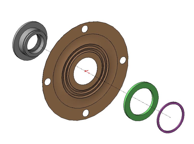
Posted by: Demick Feb 28 2006, 11:15 AM
And below is the assembled version.
Maybe Geoff or Dave can send me a bad diaphragm (OK if it is already cut in half). That way, I will be able to replicate exactly the design the factory had for this.
Demick
Attached image(s)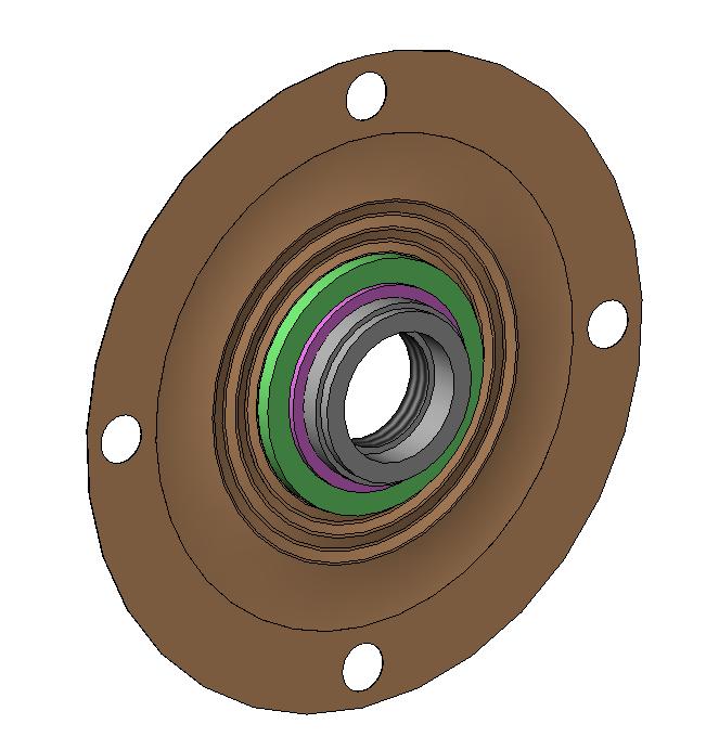
Posted by: Bleyseng Feb 28 2006, 03:26 PM
It is not a 3 piece unit but two pieces. The ring is held in place by the collar being mashed onto it at the step shown by the red arrow.
I can send you the other half piece I have sitting here on my desk. Send your address to me.
Attached image(s)
Posted by: r_towle Jun 28 2006, 10:16 AM
A bump
I still have a company that will make the berillium part.
We need metal properties, and measurements on any drawings...
Rich
Posted by: Bleyseng Jun 28 2006, 10:34 AM
yeah, what happened to this project? I keep getting requests for rebuild MPS's and I have very few good oem diaphrams to use.
RustyWA??? any further news? besides you selling your car... 
Posted by: Demick Jun 28 2006, 10:35 AM
Aw shoot. I had forgotten about this. I finished the drawings and sent them to Jeff Bowlsby, but this was during the week(s) when 914club was down and I never posted it here.
Anyway, I modeled two different diaphragms. One with the larger pleats, and one with the smaller pleats. Both were sent to me by Jeff. I don't know in what MPS's the different versions were used.
I believe that the material used on the two diaphragms may be different. One of the clues to this was that the diaphragm with small pleats was highly discolored, and the one with large pleats was nice and shiny with no sign of corrosion or discoloration. For now, the drawings call out quarter hard beryllium copper, but that can change at any time. I think the initial purpose of this exercise was just to define the shape of the diaphragm for quoting purposes.
PDF's of the two drawings are available here:
http://www.demandjen.com/914-001-Rev01.pdf
http://www.demandjen.com/914-002-Rev01.pdf
Demick
Posted by: Bleyseng Jun 28 2006, 10:39 AM
I think the large pleat is like the OEM design, the small pleats is the Brett Ins type.
Posted by: redshift Jun 28 2006, 10:46 AM

Let's just break into Brett Inst. and steal their stash of diaphrams!
Where is Miles when you need a good plan!
oh dear!
I don't have time to draw one up... find the old one, and change these variables:
Brad=Diaphram
Cops=Employees
Aaron&Matt=Whomever is close
See you at Uncle Jiggly's
M
Posted by: ppickerell Jun 28 2006, 11:06 AM
I have a little bit of experience forming beryllium Copper (33 yrs) I could make these, but the form tools would run about $2000 for each of the two designs.
Posted by: ptravnic Jun 28 2006, 11:26 AM
I commend the work you gents are doing on this. If/when it comes down to ponying up for the first batch to cover costs I'll donate $50.
Posted by: Dr Evil Jun 28 2006, 03:22 PM
Does anyone have the value curves for these? I am supprised no one has hidden a solid state MPS in the old unit that would mimic the correct signals for the given pressures. Has someon mentioned this and I missed it?
I could do it if I had the values that I needed. I may need to set up a circuit to compensate for certain variables, but it seems very doable and would keep your system looking/performing stock.
Anyone wanna work with me on this.....not like we are all in a hurry 
Posted by: Bleyseng Jun 28 2006, 03:34 PM
Here's a site to look at....
http://news.thomasnet.com/fullstory/453621/2399
We need a vacuum sensor not a pressure sensor, I have no time to delve into this.
Posted by: Dr Evil Jun 28 2006, 03:50 PM
That is what I am reffering to in part. My MJLJ has a vaccume MPS that is the size of a quater. I was just looking over the brian schematics and it looks failrly straight forward. I just need the values that I should be shootinf for, or I will take a much longer time and rig up test connectors to a running car, yadda, yadda.
I am not saying I know it all, far from it. I'm just saying that I have not seen a reason not to consider this line of thinking.
Posted by: Bleyseng Jun 28 2006, 04:00 PM
I started to look into a just haven't as I have been outta the country workin...
Its all yours baby! 
Posted by: Jeff Bowlsby Jun 28 2006, 05:11 PM
Dr. Evil Sir...
The values are on Brad Anders fine site. The MPS converts intake manifold vacuum, or rather the micro-dimensional displacement distance on a diaphragm subjected to the change in vacuum pressure...to an electical inductance value. Can you do that?
Posted by: Dr Evil Jun 28 2006, 07:28 PM
Maybe, havent tried it yet, but I am willing to give it a try
Posted by: r_towle Jun 28 2006, 10:26 PM
i guess that we never got a clear answer about the metal properties...
Hardness and alloy...
If I get that..and take these drawings, at least I can get a price.
Rich
Posted by: r_towle Jun 28 2006, 10:29 PM
Maybe, havent tried it yet, but I am willing to give it a try
I looked on thomas.net and alibabi (SP) and I found several screw in ones that measure vacuum, and produce elec....
One of the companies said they would make it any way that was needed....
So, search there...
I could possibly help provide readings...
We can talk about that...but I think I could rig up an inline system to the car to take readings and plop it all on a computer so we can map it out...
Rich
Posted by: Demick Jun 28 2006, 10:58 PM
I am not saying I know it all, far from it. I'm just saying that I have not seen a reason not to consider this line of thinking.
There are a bunch of us who have thought about this. Like you point out, a pressure sensor that outputs a porportional voltage (or resistance) is easy to get. A standard MAP sensor is cheap and readily available that would do this (Megasquirt uses a MAP sensor like this).
Unfortunately, to mimmic the MPS, you would need to take this signal and create an inductance value based on the amount of vacuum. A hefty inductance value at that (0 - 1.5H). I know of no voltage controlled variable inductor - especially at that kind of value. So this is where I get stuck. Not a simple problem.
The other approach is not to mimmic the MPS exactly, but to understand how the ECU interprets this inductance, and create a circuit that does not output an inductance, but rather another type of signal that the MPS would be able to correctly interpret. But this goes way beyond my electrical capabilities.
Demick
Posted by: Dr Evil Jun 28 2006, 11:05 PM
Demick, you hit it right on the head. I figured a veriable inductance circuit is gonna be the bain of this whole thing. I figured if it were easy one of you all would have already done it. I just wanted some input and values and such so I can start to ponder about a solution as well. I definetly wish to share what I find with the group. Like Geoff, I am not out to make a fortune on these. I want a solution so I can keep all of my friends onthe road......looking like a stud for solving this problem wouldn't hurt  But, we shall see. I have 15 years electronics experience (before med school) and am a wiz at figuring out circuits. I bet Jeff Keyzer and Tony Long could help a lot on this problem as they are EEs.
Just dont expect a fast solution....like Geoff, I too have other obligations 
Posted by: Bleyseng Jun 28 2006, 11:12 PM
email Brad Anders too Dr Evil as he has studied and understands Djet like no one else. He is also a Electrical Eng working for Intel. He mostly posts on PP or Rennlist as I think there is too much OT chatter for him here.
Posted by: lapuwali Jun 29 2006, 10:10 AM
Jeff Keyser and I have spoken about this at length.
The variable inductor in the MPS basically takes a squareish wave in (from the trigger points), and puts a squareish wave out, modified by the manifold pressure and the air temp (which gets fed back in by the ECU). This square wave is then furthur modified by the ECU, and eventually becomes the pulsewidth train for the injectors.
So, no variable inductor is really required. Instead, you use the pulse capture module on one of the many microcontrollers, read a solid-state MAP sensor, read a temp sensor, then calculate the waveform out in a very similar manner to the way normal fuel ECUs do. Generating the waveform from there is easy. 90% of this could happen in software.
However, the marginal cost of building and programming and testing this thing would exceed that of a Megasquirt kit, which solves the problem, as well.
If you were willing to eat all of the R&D costs, the final unit would likely be simpler and cheaper than a Megasquirt, partly because you could use a simpler processor, and because you'd not need a lot of parts the MS uses, like injector drivers (the D-Jet ECU would do that). Indeed, I think all you'd need is a power supply (one $5 IC, a few resistors and caps), a microcontroller (under $10 in single unit quantities), a MAP sensor (about $25), and a bit of signal conditioning (more resistors and caps, about $1). The whole thing could easily be made to fit into a MPS housing with the guts removed. You'd need to do some rewiring, as I don't think the MPS gets a solid +12 or ground connection (you'd need both).
There would probably still be some tuning limitations set by the stock ECU, so while you'd certainly be able to use this electronic MPS for any engine from a stock 1.7 up to a pretty wild 2056, I'd bet you'd run into problems with, say, a 2316 or so. Hard to say for sure.
A Megasquirt would be cheaper, far easier, and would allow more tuning flexibility.
Posted by: Demick Jun 29 2006, 10:58 AM
I think the fundamental question here is, are you trying to come up with an MPS replacement, or an MPS and ECU replacement?
An MPS replacement would retain the stock ECU, and be a simple swap out of the MPS for a solid state one. Since the MPS is the least reliable, most expensive, and hard to get item in the fuel injection system, I think this is worthwhile to try and do.
However, an MPS and ECU replacement (which James is talking about above), seems pretty pointless to me. As long as you are essentially replacing the whole FI control system, you might as well just start with Megasquirt or one of the other aftermarket FI systems and go from there. But the end result needs to be a plug-and-play system. And the hurdles for making a plug-and-play system are pretty much the same for a 914 specific custom FI replacement, Megasquirt, or any other aftermarket FI system.
Demick
Posted by: lapuwali Jun 29 2006, 11:53 AM
I think coming up with new MPS diaphrams is a good thing, since this really is a 100% plug and play solution, and would suit those who want a 100% stock car.
For those wanting a solid-state replacement, however, you only have two options. Use a solid-state MAP sensor and some amount of analog electronics to emulate the variable inductor. This would be pretty difficult to design, and I'd expect the parts count to be high, so the device would be fairly expensive to make. The other option is to use a microcontroller to do the job digitally, at which point Demick is right in saying you might as well just use Megasquirt, et al.
For a full stock appearance, it wouldn't be at all difficult to fit a Megasquirt board in a stock ECU housing, and fit a solid state MAP sensor into an MPS. This could use a stock FI harness, and would be indistinguishable from a stock setup without disassembling the ECU and the MPS.
Posted by: Dr Evil Jun 29 2006, 02:00 PM
Interesting concept. It could more easily do that for sure, but then it would be easy
Powered by Invision Power Board (http://www.invisionboard.com)
© Invision Power Services (http://www.invisionpower.com)