Printable Version of Topic
Click here to view this topic in its original format
914World.com _ 914World Garage _ Megasquirt Progress
Posted by: yarin Jan 28 2006, 01:36 AM
Tonight I have completed building the main board for my MS II V.3.0 system. Thanks to those that have helped out. Once i'm all finished I will definitely post a complete "How To MegaSquirt a 914" website with pics and step by step. So far i'm still at the desk level. I've got 2.0 injection parts on the way.
I'll be using the following:
stock injectors
GM air temp sensor
stock fuel pump
summit racing manifold referenced fuel pressure regulator
stock injectors (i think 2.0s are on the way)
stock plenum / runners
stock CHT
MS Relay Board
Innovative WB02
High Current ignition driver
Stock dizzy with pertronix (hall sensor)
Stock Bosch Blue Coil
PWM Low impedence injector driver (no resistors)
Stock Cold start Valve (plan so far)
Stock throttle body with some junkyard TPS
Here is a pic of my board, took me a few hours a night every night this week. I took my time, double checked everything. So far so good!
I don't expect to have the system in the car for at least another month. I'm converting from carbs so I want to install steel fuel lines and clean some stuff up.
I'll be sure to post progress in the forums. 
Attached image(s)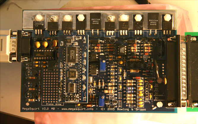
Posted by: yarin Jan 28 2006, 01:39 AM
my converted workshop... temporary of course
Attached image(s)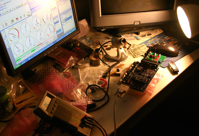
Posted by: yarin Jan 28 2006, 01:40 AM
shot of my soldering skills at the beginning.
Attached image(s)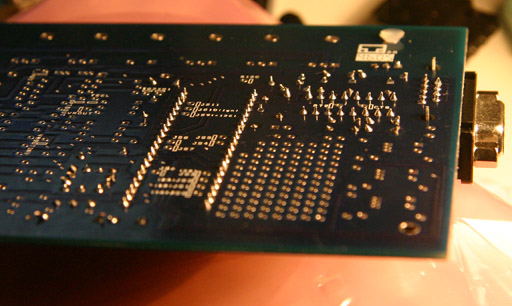
Posted by: dinomium Jan 28 2006, 01:41 AM
Yes, the injetors are the pretty green ones! But like I said, they have been sitting awhile!
I dont know if I could stand that much soldering...

Posted by: Tom Perso Jan 28 2006, 06:51 AM
Looks familar... 
If you're thinking about a junkyard TB, look into the Volvo 240 TB. It's got an adjustable idle by-pass, runs a Bosch TPS, and should fit onto a 2.0L plenum after welding on an adapter.
Big Picture.
Tom
Posted by: Mueller Jan 28 2006, 10:08 AM
I highly recommend testing the injectors "before" installing them....it might save a lot of time and grief from uneven flowing or poor flowing injectors, BTDT 
http://www.cruzinperformance.com/fuelinj.html
Posted by: yarin Jan 28 2006, 10:27 AM
I was planning on sending my injectors out to RC Engineering. I've used them before.
http://www.rceng.com/service.htm#INJECTOR
However Cruzin Performance offers a seemily identical service (ultrasonic bath and flow test) for 1/2 the price!!
Thanks for the link! I'll be sure to check out Cruzin Performance.
Posted by: crash914 Jan 29 2006, 10:12 AM
Yarin,
You will like the version 3 system...
I just completed the upgrade to by 2.2 board with the MSII chip. I had a little issue with the cold start enrichment.
I LOVE the autotune!!! to get the cold start problem licked, I richened up the fuel map. Then I drove around...very heavy bogs and non running...
Leaned it out, manually smoothed out the map, now goes like stink!!
I like this better than megatune. Real time.
Now I have to adjust my rev limiter. I am using fuel cut out at 6000 rpm. Too Low!!
I rev so quick and am still pulling at 6000. I did a quick run through the gears just to see if I still had some pinging and stumbling. Gone!
Pulled very strong to 6000 in 3rd gear. I felt like I have got at least 1500 rpm more to play with. Felt like I could run at 6k all day! Can't wait for 7000K in 5th. should be scary fast....
herb
Posted by: Tom Perso Jan 29 2006, 11:30 AM
| QUOTE (crash914 @ Jan 29 2006, 11:12 AM) |
| I just completed the upgrade to by 2.2 board with the MSII chip. I had a little issue with the cold start enrichment. |
The MSII chips is available now? When I looked to upgrade my 2.2 board, those chips were in short demand. I may have to look into that.
Where did you order the upgrade?
Tom
Posted by: yarin Jan 29 2006, 02:31 PM
I ordered my stuff from http://www.diyautotune.com/
Excellent service, lightening fast turn out times for both orders I placed with them.
If you are going to build your own MS system I would definitely order from them. All of the parts came in bags, labeled with all the info, very easy to find. Prices are basically the same everywhere. Their kits include the housing, heatsink conductive paste, and all the little things you need.
Herb,
I can't wait to get this thing installed in my car. I've got injection parts on the way, one step at a time though. You car does sound scary fast, did you get it dynoed yet? 7K rev limit is high, i bet thats a thrill ride!
Tonight i'll start on the relay board and play some more with megatune. I just found a laptop I can use for tuning once its in the car. 
Posted by: crash914 Jan 30 2006, 06:35 AM
msII drop in chip is available...you can buy on line from Al Grippo. The address escapes me right now..
yea the car is fast...makes my bmw seem like it can't get out of its own way..
I do have double valve springs and a high torque cam... I can't think what would happen if I had a light flywheel...
Posted by: alpha434 Jan 30 2006, 11:21 PM
Bump.
Megasquirt?
Posted by: Mueller Jan 31 2006, 12:23 AM
| QUOTE (alpha434 @ Jan 30 2006, 10:21 PM) |
| Bump. Megasquirt? |
megasquirt = do it yourself (stuff a bare PCB or buy a preassembled kit) fully programmable fuel injection (with spark on some versions)
I did my MS (megasquirt) install for about $250 bucks for parts, it replaces the factory ECU, then you need a new TPS, you can use the factory air temp sensor and CHT and injectors......
it's being run on just about everything from 2 cylinder harley engines to 426 Hemi engines....turbo, normally apserated, supercharged, you name it.....
for the price, it cannot be beat, period...
see MSEFI.com for more details
Posted by: alpha434 Jan 31 2006, 12:28 AM
ok. So... Outside of price. What kicks it's ass?
Posted by: Mueller Jan 31 2006, 12:58 AM
| QUOTE (alpha434 @ Jan 30 2006, 11:28 PM) |
| ok. So... Outside of price. What kicks it's ass? |
you could pick just about any of the latest digital fuel injections systems around and they could be better or worse than the Megasquirt, it's all up to you , the tuner and installer of the fuel injection....a $4,000 MoTec won't do any better if you don't tune it correctly and do a nice clean install......
the whole idea of the MS is for the DIY'er and tweaker to modify to their hearts content since the software is open source (which you do not have to know or care about if you don't want to)
the MS is for those that want to learn and know how to search for the answers (pretty good web support and install manual)...if you need a fuel injection with a fancy name or phone support and a warrenty, then the MS is not for you.....
Posted by: alpha434 Jan 31 2006, 01:04 AM
Ahhhhhh. I see. So nothing. Hmmmm....
Replace my L-jet?
Hmmmm....
Build new engine?
Hmmmm....
With titanium?
Hmmmm.....
Eureka!
Posted by: Mueller Jan 31 2006, 01:13 AM
| QUOTE (alpha434 @ Jan 31 2006, 12:04 AM) |
| Ahhhhhh. I see. So nothing. Hmmmm.... Replace my L-jet? Hmmmm.... Build new engine? Hmmmm.... With titanium? Hmmmm..... Eureka! |
replacing a working L-Jet with the MS on a bone stock motor won't really gain you anything except the chance to fine tune and monitor all of the sensors and inputs via a laptop...once you start tweaking the engine with a hotter cam or way bigger pistons/cylinders, then the MS is nice cause it'll be way, way easier to compensate for the new setup.....
most people use the MS for bigger/hotter engines or for easy turbo/supercharger installs....there are a few people running the MS on stock motors, I ran an MS on a 1.8 years ago when it 1st came out...no real reason to do so, I just felt like taking off the L-jet and playing with the MS...worked great

Posted by: alpha434 Jan 31 2006, 01:19 AM
Alright. The next objective for my top secret project B. Hmmm. The branch group is going to do just fine......
*where's the evil smilie?
Posted by: agrump Jan 31 2006, 07:36 AM
Yarin,
I have a similar setup to what you are planning, MSII/v3. A few hopefully helpful notes, you will need a 1k bias resister for the pertronix to work cleanly. I found the bosch blue coil caused noise on my system but others seem to be able to use it fine. If you plan on doing fuel first and just get a signal from the coil then R57 will need to be increased, I think mine is ~750 ohms. I started like this and recently swtch to having MS control spark. I did not have to change R57 back to the original value, it worked fine. I did have to change the predictor algorithm to "last interval" to get a stable spark output. I'm using a locked 009 distributor by the way. DNHunt posted a great timing table on this board, it works great for me, better then my old mallory setup especially at high rpms.
Where are you planning on mounting the boxes? I have the relay box mounted near the battery on the firewall and the MS box under the arm rest. I mounted the relay board in the lowest slot of the box and cut holes in the cover so the relays would fit. The cover makes it look clean but if I ever have to access the fuses/wires on the side of the road it's going to be a pain.
I hope this is useful.
Posted by: yarin Jan 31 2006, 09:28 PM
Hey Dean,
Someone on MSEFI forums used a 1.3K pulldown resistor for the signal of the dizzy, i was planning on doing the same. I haven't decided if i'm going to do fuel and spark first or just start with fuel. If I trigger off the coil do I need an Ed Capacitor and Wing Diode installed? I dont want to have to modify my board too much just to get dizzy trigger working for a few days.
Are you using points or petronix?
I will be mounting my relay box behind the drivers seat in the engine compartment. The MS box will go in the dash i think. It's a race car, so there isn't much interior.
I was thinking about mounting the relax board on the lowest position, but I worried a tiny bit about electrical gapping from the relay pins to the box since its so close. Did you buy the entire box with cover? My kit didn't come with a cover. You could consider filing the side mating surfaces of the top cover and not using the side panel screws. Instead use some type of removeable strap or even hinge the cover on the base.
I'm sure i'll have a bunch of questions for you. here are a few..
Are you using the stock fast idle solenoid? Did you configure your board for PWM for low impedence injectors? What did you do for warm up enrichment? Are you using the stock CHT sensor? Can I take a look at your easytherm values and warm up enrichment tables? Which TPS did you use? Did you tune with auto-tune and a WB02?
I had some free time at work today so I created a diagram of the entire MS job with WBO2. It's 95% there, i'm sure i'll have modifications to it once I start the installation. I might build a secondary terminal box for grounds and +12V lines, I also want to run a few extra lines in the relay cable and hook them up to a breakout box to make any future additions easy.
So check out my diagram, enjoy! It's a big file!! 500K, i had to bump up the res so u can zoom in and see the 6 point text. So once you download it zoom in to 100% to see all the fine stuff. I'm pretty happy with it so far, i'm sure it will be a great help once i start wiring.
http://coewww.rutgers.edu/~yarin/914-MS2.jpg
Posted by: DNHunt Feb 1 2006, 08:21 AM
One piece of advice. Plan your cable from the ECU to the relay box carefully. Try to avoid routing that leads to bends at the DB 37 connectors. This IS the weak spot of the system. The DB 37 offers very little stress relief and the solder joints can break. I had this happen in a Friday commute. Not fun. Luckily I had my laptop and I reprogrammed the VE table so MS ran with no MAP input. One of the things holding me back from building my V 3.0 board is a search for an alternative to the DB 37. A trip to Boeing surplus is in order. It is undoubtedly the best junkyard in the world.
I would go so far as to plan on having to repair that cable. In other words, think about how you can get to the ends of it to solder. Mine goes through the firewall and the hole in the firewall is not big enough for a DB 37 to go through so I have to solder with the cable in the car. The advantage is that my FI harness can be dropped with the engine or can be removed for changes.
Dave
Posted by: yarin Feb 1 2006, 08:33 AM
Dave,
I will be sure to strain relief both sides of the DB-37 cable properly. Actually I have the perfect solution.. I have tons of these little things available at work. Just 1 screw into any surface and a quick ziptie.
I visited Boeing 7-8 years ago when i was on vacation in Seattle. I would KILL for a trip to their surplus yard. I work at a semiconductor company that cleared out a bunch of their old stock, a lot of stuff was chucked. Sooo sad.
Since only about 1/2 the pins are used on the cable wouldn't it be nice to build a MS system with two nice big sturdy LEMO connectors?  Those things aren't cheap, but they are bulletproof. Maybe a combo of that and a big 8 pin COAX Sub-D for the injector signals, dizzy pickup and power signals.
Attached image(s)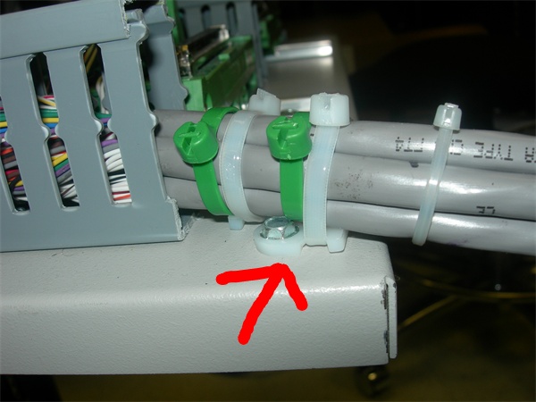
Posted by: DNHunt Feb 1 2006, 08:42 AM
As a guideline I have a 180 degree turn a the relay board end of the cable. I have it tied down so the bend is about a 6" diameter and I have had to repair this twice in about 3 years. Definitely not fun.
Dave
Posted by: bd1308 Feb 1 2006, 08:45 AM
BNC connectors!!!?!!?!?!
those things are nuts.
Posted by: yarin Feb 1 2006, 08:48 AM
I bought the 12' cable from DIYautotune.
The finished end is crimped, the other end is do it yourself solder cup. Should I connect the solder cup end at the MS and the crimped end at the relay board?
Posted by: agrump Feb 1 2006, 08:55 AM
Yarin,
I am using a pertronix. I did not use the Ed capacitor, I just changed the resister. I know what you mean about changing something and then having to change it back. I was pleased that I did not have to change the R57 back once I started controlling timing.
I did get the cover. I got it a long time ago when I was running MSI/V2. Godd idea about attaching the cover. Be warned that if you do decide to mount it low it is tough to get the wires into the terminals especially if two or more need to be connected to the same one.
I am using the stock fast idle device. I stole one of the connections for the IAC to use for my MAP sensor which I have mounted in the relay box. SInce I started with MSI/V2 I built a resister box for the injectors and am still using it so no PWM. For warm up enrichment I am using the stock head sensor. I manipulated the table so that it reads about 100 degrees lower the the actual temperature. It works ok but still cuts off to soon. There is a limit to what you can do by changing the tables, I think I got it about as good as it is going to get with the stock sensor. I am thinking about mounting a sensor next the the stock thermostat and see if I can get better readings there. With MSII you don't have to mess around with loading thermal tables there is a menu item under tools in megatune that will handle it for you. I am currently using:
5280 ohms -40 degrees f
2000 ohms -6 f
200 ohms 130 f
Again it is not perfect. Interestingly MSII limits the lowest temp you can enter to -40, I was using -48 with MS1 for the first entry.
I found a tps that fit within the plastic cover of the stock throttle switch. I wired it into the stock connector, it looks factory. I will try to dig up where I got it, it was online somewhere. Attached is a screen print of my warmup settings. I used VEXME software to tune my tables with a LC1 WB. I am playing around with the PID algorithm currently, the simple WB algorithm seems to oscillate to much.
I am with Dave in not trusting the stock connector although I have not had a problem YET. The minisquirt has a much nicer one but I can’t imagine changing it now, what a pain that would be!
Attached image(s)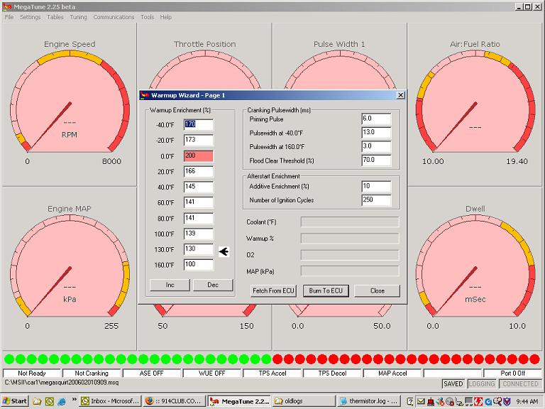
Posted by: DNHunt Feb 1 2006, 08:57 AM
Also on the injectors and fuel pressure. I believe the stock 2.0l injectors are designed for 28-36 psi. On the low side atomization is poor and on the high side the pintle has problems closing. I'm kind of fuzzy on that.
One thing to look at Borg Warner makes replacement injectors for some if the later Bosch L-jet and K-jet systems. The output is way less so they are easier to control. These are barbed fittings in some cases and they all use the improved l-jet electrical connectors. Also, they are cheap. One problem the hoses are not swedged to the barbed fitting well at all and may leak. It's best to redo them with good FI clamps.
The resolution with the MSII chip is 100X more sensitive that the MSI chip so you will be able to tune pulsewidths very well. I plan on using my 2.0l injectors and I expect it to be very smooth indeed. I ran a fuel only program that had 10X resolution before (Hi-res code) and it was very smooth. Unfortunately MS extra doesn't have the room for this. The 100X resolution was a big consideration for me to upgrade.
Dave
Posted by: bd1308 Feb 1 2006, 08:59 AM
If i do this on my 1.7, is there someone that could help me out?
b
Posted by: sgomes Feb 1 2006, 09:02 AM
LEMO 
Posted by: yarin Feb 1 2006, 09:09 AM
Check these out, FCI D-sub Mixed Power DW series
Not cheap.. but would also work for a PCB mount all in one cable. Plenty beefy with the right mating connectors and strain reliefs.
Attached image(s)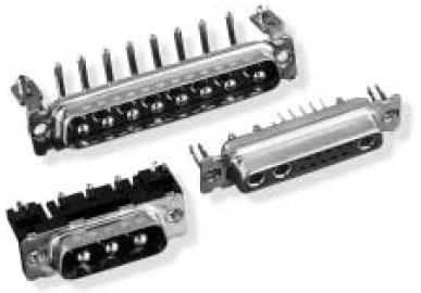
Posted by: DNHunt Feb 1 2006, 09:13 AM
Britt
There is plenty of support online. Meuller could do it and it worked until he spilled coffee on it. I'm a dentist that can't tell you how a diode works or why it is in the circuit. I can't program in assembly or C, but I read and absorb things. MS just needs a couple of things to really work.
Research, plan your instal before you start. Once you decide where you want to go resist changing things midsteam.
FOLLOW the instructions. It's like cooking, if you follow the recipe it will work.
Take your time and ask questions if you are confused. It's no different than school. If you ask enough people someone will explain it in a way you can understand.
Be ready to problem solve in a LOGICAL step by step sequence. Something will go wrong and you will have to figure it out.
When you get done you will have a basic understanding of FI and something that you can be proud of.
Dave
Posted by: yarin Feb 1 2006, 10:56 AM
| QUOTE (DNHunt @ Feb 1 2006, 06:57 AM) |
| Also on the injectors and fuel pressure. I believe the stock 2.0l injectors are designed for 28-36 psi. On the low side atomization is poor and on the high side the pintle has problems closing. I'm kind of fuzzy on that. One thing to look at Borg Warner makes replacement injectors for some if the later Bosch L-jet and K-jet systems. The output is way less so they are easier to control. These are barbed fittings in some cases and they all use the improved l-jet electrical connectors. Also, they are cheap. One problem the hoses are not swedged to the barbed fitting well at all and may leak. It's best to redo them with good FI clamps. The resolution with the MSII chip is 100X more sensitive that the MSI chip so you will be able to tune pulsewidths very well. I plan on using my 2.0l injectors and I expect it to be very smooth indeed. I ran a fuel only program that had 10X resolution before (Hi-res code) and it was very smooth. Unfortunately MS extra doesn't have the room for this. The 100X resolution was a big consideration for me to upgrade. Dave |
Dave,
If the 2.0 injectors that are on the way are good i'll keep em for now. My original plan was to build a intake plenum, maybe individual throttle bodies.. but that has been put on hold.
Thanks for the info on the Borg Warner injectors. I'll hold off till I can build an intake manifold with all the goodies and pickup better suited injectors.
If there are atomization problems with the 2.0L injectors at low fuel pressure and pintle closing problems at higher pressure why are you going to use them? What pressure should I run them at? I'm going to use Summit's modified adjustable manifold referenced fuel pressure regulator. http://store.summitracing.com/default.asp?target=partdetail.asp&autofilter=1&part=MSD-2222&N=115+4294880914+4294891681+4294846511&autoview=sku I don't want to end up with low fuel pressure(manifold vacuum) causing atomization problems. Is there any type of feedback I can look for aside from volume flow bench testing?
Posted by: yarin Feb 1 2006, 11:02 AM
| QUOTE (bd1308 @ Feb 1 2006, 06:59 AM) |
| If i do this on my 1.7, is there someone that could help me out? b |
There are enough people on this forum that have squirted their 914s that can help you. Also check out the MSefi.com forums. There is tons of info on building and tuning your MS system. That's where everyone on here got most of their MS specific questions answered. I'm in the build process right now and have received plenty of great information.
THANK YOU 914 MEGASQUIRTERS!
The real tricky part coming with tuning, i'm about a month or two away from task. See my link earlier in this thread. I created a diagram for all of the MS wiring on a 914 with the accessories. At least it's what i'm planning on doing.
Next step is finding a TPS from a junkyard. Gotta get my throttle body first, 2.0 parts(injectors, plenum, runners, etc) should be here Friday.

Posted by: lapuwali Feb 1 2006, 12:26 PM
IMHO, Dave's experience with solder cup DB connectors is exactly why you should NOT use them in a car. Use DB connectors with crimp-on pins. They're more expensive to buy up front (esp. as you have to buy the right tool to crimp the pins), but they're much more reliable in a high vibration environment.
The other thing I intend to do, and I'd suggest for others, is to mount the board in an oversize box, and run the DB connectors to some other connector that connects to the box side. My actual plan is to put the stock metal box with endplates, but the connectors not tied to them (metal box for EMF protection), and place THAT in a waterproof plastic case. A short cable will connect the DB connectors to waterproof connectors that pass through the plastic case walls. My setup will go in the engine bay.
I'll also rubber mount the metal case inside the plastic case to reduce as much as possible the vibration passed to the board itself.
Mark Henry has had good luck mounting his SDS inside the stock ECU case, and that's also an excellent option. I may still end up doing that myself, since I have a couple of useless 1.7 ECUs. The MS relay board and the MS itself should fit inside the stock ECU case quite nicely.
2.0 injectors will work, just run them at stock D-Jet pressure: 29psi (2 bar). Most injectors now are run at 3 bar (43.5 psi), which is too high for the D-Jet injectors. The main difficultly with 2.0 injectors is they're HUGE for the stock engine, presenting some problems with idle pulsewidths, which are usually down around 2msec. The MS resolution of 0.1msec means you have a minimum step of 5% at such small pulsewidths. Use a manifold pressure referenced fuel pressure regulator (see posts by airsix on how to convert a stock FPR) to help significantly here. You can also sell the 2.0 injectors and find a set of 1.7 injectors instead, which are still plenty large enough for even a modified 2270, yet small enough that idle pulsewidths are a good bit longer, giving you more headroom to get the idle tuned right. Since D-Jet is all analog, it has no "resolution" on pulsewidths, so it can run the injectors right down to their minimum pulsewidths (about 1.7ms) with infinite control.
D-Jet injectors are mostly used because they fit the stock intake setup well. There aren't many hose-barb injectors to choose from. Most need a fuel rail. 1.8 Subaru injectors work (and are smaller than 1.7 D-Jet injectors), as do some L-Jet injectors, and both of those injectors will work at 3 bar, which will give better atomization than 2 bar D-Jet injectors. I intend to use 1.7 D-Jet injectors, because I have several sets on hand, including a NOS set still in original boxes.
Posted by: yarin Feb 1 2006, 02:51 PM
James,
Thanks for you feedback. I will run the injectors at 29psi. However the fuel pressure regulator sold by summit claims 36-45Psi. Someone on her said their regulator is a modified stock D-jet regulator. I would hope that I can turn it down to 29psi. I guess time will tell. It's pretty difficult finding a manifold referenced adjustable fuel pressure regulator for the 29psi range for under $200. Do you think I will be ok?
I'm looking at Digikey p/n HM131-ND for the plastic enclosure for the relay board along with the clear lid 1591EC-ND. It's not water tight, but water resistant. I will secure some form of hood over the cable entry/exit holes to defect any water that may happen to enter the area. I was also planning on using rubber mounts to dampen road vibrations.
I was afriad that the solder cup connections would become unreliable due to stress and vibration. Crimp is the way to go, assuming you have proper tooling. Pliers and a screwdrivers will yield a less reliable solution than a solder-cup connection IMO.
Can you explain your EMF solution? Are you avoiding grounding the metal case? Is this the way to go?
Thanks for the info!
Posted by: jhadler Feb 1 2006, 03:06 PM
The stock D-jet regulator is pretty good. You say "manifold referenced", do you mean rising rate? Why do you want the fuel pressure to change? You've already got an ECU that can be programed to compensate for manifold pressure. Seems you'd be adding yet another variable that you don't need.
Are your injectors failing to work at idle or redline? If they're good there, why do you need dynamic fuel pressure changes? Maybe I'm missing something?
-Josh2
Posted by: yarin Feb 1 2006, 03:22 PM
Josh, Yes rising rate. Or in our case when the manifold is under vacuum the fuel pressure is regulated to ambient - vacuum. If the manifold is boosted, Fuel pressure increases proportionally. Unfortunately the latter condition doesn't come in to play for me 
From the MS site:
"The vacuum referenced fuel pressure regulator is essential. It provides constant pressure differential between fuel at injector nozzle and manifold air pressure [port EFI] or atmospheric pressure [TBI]. This makes the injected fuel quantity solely a function of the injector open time.
If you were to 'cap off' the manifold vacuum port on the fuel pressure regulator, you are reducing the dynamic range of the injectors. This means you will need lower pulse widths at at (giving less control over idle mixtures) and lower flow under boost (restricting the maximum horsepower).
So, in general, for port injectors, have the fuel pressure regulator connected to the manifold vacuum is a good thing. There is very little reason not to do it (though some have argued against it for individual runner port EFI set-ups). "
Since 2.0 injectors are rather large I was under the impression that I would run into minimum pulse width limitations at idle, therefore lowering the fuel pressure at idle would help. Correct? Or would PWM take care of those issues?
Thanks
Posted by: lapuwali Feb 1 2006, 03:25 PM
You can modify the stock D-Jet FPR to reference it to manifold pressure yourself. Search here for posts by airsix, he covered it in detail. It's pretty simple, basically just drilling a hole and fitting a small tube with epoxy will do. If you don't have a stock FPR, you can pick them up on Ebay pretty cheap. I may even have a couple lying around in the parts bin. I'd send you one for shipping if you're game to try the conversion yourself.
On EMF, I was planning on running the ground connections from the DB connector to a bolt through the outer case, then one big ground wire from that bolt to a case bolt. Another connection from the inner (metal) case to the bolt will ground the case, and allow me to run a lot fewer wires through the outer case connector. If I put the whole mess in the stock ECU case (which is sounding more and more attractive every day), I'll not have an inner and outer box, just the metal ECU case, but I'll still do the ground bolt trick. I'll also make a plate to cover the stock connector hole and run my waterproof bulkhead connectors there. One for EFI signals, one for serial signals (with a cap for when the serial cable isn't connected).
Josh, you want a manifold referenced FPR to keep the fuel pressure differential across the injector the same. If the rail pressure is fixed, then the pressure differential across the injector goes UP as manifold pressure goes DOWN. Manifold pressure is low at low loads, and high at high loads, so the pressure differential across the injector is high at low loads and low at high loads, which is the opposite of what you want. You have to compensate for this by making the difference in pulsewidths wider, but you can hit physical limits at either end. The injector cannot open and close in less than ~1.7ms, so if you need t make it shorter than that to compensate for the high pressure differential at idle, you can't get the idle to be lean enough. Injectors also can't be open longer than 80% of the time without overheating, so you may not be able to make the pulsewidths long enough at high loads to overcome the lack of pressure drop across the injector with 1.0atm in the manifold.
With a manifold referenced FPR, however, the differential across the injector is fixed regardless of manifold pressure, so you end up with longer required pulsewidths at the low end, and shorter required pulsewidths at the high end, for the same fuel flow through the injector. Thus, you can run smaller injectors than you might be able to otherwise, and thus get more tuning flexibility at the extremes.
Posted by: lapuwali Feb 1 2006, 03:41 PM
| QUOTE (yarin @ Feb 1 2006, 01:22 PM) |
| Since 2.0 injectors are rather large I was under the impression that I would run into minimum pulse width limitations at idle, therefore lowering the fuel pressure at idle would help. Correct? Or would PWM take care of those issues? |
PWM is there to limit current through low-impedance injectors (and the D-Jet injectors are low-impendence).
Basically, since current = voltage/resistance (so Mr. Ohm said), if you lower the resistance, and the voltage stays the same, the current increases. For our purposes, impendence = resistance, so low-resistance injectors will allow too much current to flow through them (overheating them) unless you provide some way to limit the current. L-Jet uses external ballast resistors to do this. MS gives you the option of using external resistors, or using PWM to limit the current. PWM works using a "peak and hold" strategy. It delivers a full 12v at first to get the injector to pop open, then it starts to switch the voltage on and off rapidly (too fast for the injector to react), and the duty cycle of the switching lowers the average voltage seen on the circuit. Lower the voltage, with fixed resistance, and you lower the current. D-Jet does this, too, but it can actually lower the voltage directly, since it's an all analog ECU. It doesn't have to resort to digital tricks like PWM.
Using peak and hold instead of just limting the current with external resistors means you get faster response times from the injector (particularly in opening), so, again, you gain a bit in injector dynamic range at the idle end of the spectrum. L-jet just copes with slower response times for a simpler circuit, and L-Jet can't handle large injectors easily, as a result. L-Jet is famous for leaning out on top, as a result, as it must use pretty small injectors to idle well, and that's where all emissions testing is done.
Posted by: DNHunt Feb 1 2006, 04:48 PM
I understand the rising rate FPR but, I haven't found it necessary and I'm not going to mess with it.
I've only had a few grips. The idle flucuates with alternator load (I can't imagine running AC) so idle control would be nice. Over run is difficult to tune but was very acceptable with the greater resolution of the Hi-res code. I suspect that will also be the case with MSII. The IAT compensation is off due to heat soak of the sensor in the plenum. Both idle control and air density corrections are being worked on by other people with similar problems.
The basic B&G codes for fuel only give a nice replacement for D-jet with the benefit of tunability. Adding ignition control helps even more but, the system is not perfect and is still short of what most of us are used to with modern FI.
All in all I've been very happy with my stuff. I've had to repair a couple of solder joints, replace 1 transistor and 1 MAP sensor in 3 years and about 8000 miles. The same board has been used with 3 separate engines and in 2 forms (feul only and fuel with wasted spark distributorless ignition). I can't begin to remember how many different code versions I've used.
Posted by: lapuwali Feb 1 2006, 05:13 PM
| QUOTE (DNHunt @ Feb 1 2006, 02:48 PM) |
| I understand the rising rate FPR but, I haven't found it necessary and I'm not going to mess with it. I've only had a few grips. The idle flucuates with alternator load (I can't imagine running AC) so idle control would be nice. Over run is difficult to tune but was very acceptable with the greater resolution of the Hi-res code. I suspect that will also be the case with MSII. The IAT compensation is off due to heat soak of the sensor in the plenum. Both idle control and air density corrections are being worked on by other people with similar problems. The basic B&G codes for fuel only give a nice replacement for D-jet with the benefit of tunability. Adding ignition control helps even more but, the system is not perfect and is still short of what most of us are used to with modern FI. All in all I've been very happy with my stuff. I've had to repair a couple of solder joints, replace 1 transistor and 1 MAP sensor in 3 years and about 8000 miles. The same board has been used with 3 separate engines and in 2 forms (feul only and fuel with wasted spark distributorless ignition). I can't begin to remember how many different code versions I've used. |
Idle control really is a hard thing to do. Someone noted that the early GM ECUs they were hacking on devoted 1/3 of the code just to idling.
It seems a simple task: read the idle speed and adjust things to keep it at that speed. However, there's usually a lag between tweaking a knob and seeing the change in the idle speed, so a simple feedback loop will spend all its time hunting for the right idle speed. The trick is getting the cycle time of the "hunt" fast enough and in small enough steps that the driver won't notice it.
The current state of the art, as I understand it, is to vary ignition timing to alter idle speed, as that has the fastest response time. However, this doesn't work for "fast idle" for warmup (not enough usable range), so you need an air control valve, anyway. Now you're controlling idle speed two ways. As battery voltage fluctuates, injector response time changes, so you get different fuel flow rates depending on alternator load. It's a small effect, but significant at idle, so you have an independent variable controlling idle speed in addition to the airflow and ignition timing you have control of.
Now you know why even big auto manufacturers usually bought their injection systems from Bosch rather than build their own. It's a hard problem, requiring a lot of effort and research to solve. I'm sure Dave didn't mean to denigrate B&G's efforts, just pointing out that two guys doing this part time (now along with a dozen or so other volunteers making significant contributions) have done a pretty amazing job just getting close to what Bosch has spent nearly 40 years perfecting.
I'll be interested to see how you get on with MSII, Dave. The code is still very new, so I'm going to stay away for now. I'll probably just do fuel only for quite some time, since I have a Mallory to handle ignition. The new Microsquirt board may actually be a better bet than MSII, as it uses the same processor, but with far fewer parts on board, so it should be more reliable. The MAP sensor is moved off board, which is probably a net win, really. By the time I'm ready to jump to ignition control, Microsquirt will probably be on it's second version and fully debugged.
Posted by: agrump Feb 1 2006, 06:56 PM
| QUOTE (DNHunt @ Feb 1 2006, 02:48 PM) |
I've only had a few grips. The idle flucuates with alternator load (I can't imagine running AC) so idle control would be nice. Over run is difficult to tune but was very acceptable with the greater resolution of the Hi-res code. I suspect that will also be the case with MSII. The IAT compensation is off due to heat soak of the sensor in the plenum. Both idle control and air density corrections are being worked on by other people with similar problems. |
I got around the IAT heat soak problem by welding a new bung in the stock location and using a GM sensor, works like a charm. For AC up idle I used an adjustable air bypass, I think it was from a vw rabbit. I just have it wired into the AC clutch. Idle still fluctuates but it doesn't stall and I don't have to run high idle speeds when the AC is off.
I have not found the overrun cutoff in MSII, at least not like MSI had. All I can find is the decel cutoff. In some ways I like the extra code better then the MSII. EGO settings in MSI was easier to understand and set then in MSII.
Posted by: yarin Feb 1 2006, 07:01 PM
Do a search for closed loop idle on MSEFI.com forums and a few interesting topics come up.
One guy changed his spark advance table and advaned spark right below his idle level.
See this table:
http://www.msefi.com/viewtopic.php?t=15094&highlight=idle+speed
Obviously this won't work for warm up enrichment because your fast idle mechanism is going to keep the engine speed far from your low idle spark advance. Question is will the idle bounce off this advance and oscillate back and forth. This is where a table larger than 12x12 would come in handy.
With the FPR issue it sounds like the modified D-jet adjustable regulator is the best bet. I've seen the thread on modifying a stock FPT to reference it to the manifold. I might give that a shot instead of buying one for $60, might as well do it myself. Here is the page.
http://www.dune-buggy.com/turbo/fuelsystem.htm
Posted by: lapuwali Feb 1 2006, 07:09 PM
Case in point: this guy is devoting a third of his advance map to idle...
Advancing the timing below the idle speed is a common trick. Dave is doing it, too. The idea is the advance will move the speed up until it chokes from too little air, then it will fall back. This may cause some oscillation, but it's better than stalling.
Posted by: Jeff Nelson Feb 1 2006, 07:15 PM
I think there might be some confusion as to what a rising rate FPR is versus a manifold-pressure referenced FPR. (Both change FP as a function of manifold pressure.) The later changes the FP 1:1 with manifold pressure whereas the rising rate FPR can be adjusted to change at some other ratio. For guys that run boost that can be a good thing. If you think of "rate" as "rate of change" then "rising rate" would be a rising (increase) in the "rate of change". For instance the rate may be 1:1 at idle but increase to perhaps 1:3 at boost. I'm not familiar enough with boosted applications to explain why this is desirable.
Are the specified components in MS spec'd for the temperature range experienced in the stock ECU location of a 914 engine bay? If so then that is a nice place to put it.
I've got a 2.0 and have some concerns regarding the use of the 2.0 injectors. One is the excessive flow capability and getting a good idle and the other is the electrical connection. I understand that the L-jet injectors have a superior connector. Do they work with the D-jet mounting components, that is the part that clamps the injector? What would be a specific L-jet injector that would flow more like the 1.7 D-jet parts but have the better connector? Would the 1.8 Subaru injector mount ok with the stock D-jet parts? What is the connector on the Subaru part? There is a good page at SDS showing a number of different injector styles: http://www.sdsefi.com/injectors.htm (This page indicates that the Subaru connector is not the one used on an L-jet injector.)
Posted by: lapuwali Feb 2 2006, 01:06 AM
| QUOTE (Jeff Nelson @ Feb 1 2006, 05:15 PM) |
| Are the specified components in MS spec'd for the temperature range experienced in the stock ECU location of a 914 engine bay? If so then that is a nice place to put it. I've got a 2.0 and have some concerns regarding the use of the 2.0 injectors. One is the excessive flow capability and getting a good idle and the other is the electrical connection. I understand that the L-jet injectors have a superior connector. Do they work with the D-jet mounting components, that is the part that clamps the injector? What would be a specific L-jet injector that would flow more like the 1.7 D-jet parts but have the better connector? Would the 1.8 Subaru injector mount ok with the stock D-jet parts? What is the connector on the Subaru part? There is a good page at SDS showing a number of different injector styles: http://www.sdsefi.com/injectors.htm (This page indicates that the Subaru connector is not the one used on an L-jet injector.) |
The MS processor (HC08GP32) is a 70dC part, and so is marginal in some places on the 914 that get pretty hot. The rear trunk, for example, appears to get too hot on a hot day. The front of the engine bay, from previous measurements, doesn't seem to get much more than 10dC above ambient, so unless you're driving across Death Valley in mid-summer at high noon, you're OK. The MSII processor (HC12) is a 125dC part, so it's plenty safe even sitting on the engine itself.
L-Jet injector connectors work with D-Jet injectors. The D-Jet injector connector is pretty bad, just slotting into the outer plastic bit fairly loosely and depending on a rubber shroud to hold it in place. The L-Jet connector has a plastic surround that covers the electrical connection, and has a wire clip to hold it in place. You may have to do a bit of cutting on the L-Jet connector surround to get it to fit perfectly, but it will fit.
L-Jet was used on a zillion cars, so find a car with an approximately similar cylinder size that was made in the early to mid 80s, which increases the chance of it using a hose-barb fuel connection, instead of a fuel rail. I know some Italian cars (V6 Alfas) used the hose-barb L-Jet injectors throughout the 1980s, and the 2.5 V6s have roughly the same cylinder size as a 1.7 four. The SDS site also has a handy chart showing flow rates v. max horsepower to give you a rough idea of sizing. The 914 1.8 used L-Jet with what's otherwise a 1.7 plenum and runners, so "L-Jet" injectors, at least some of them, are identical to D-Jet injectors.
I wouldn't be TOO hung up on the large size of the 2.0 injectors. If Dave has gotten in running with the fixed pressure FPR (and I have no doubt that he has), then it will work. You may find it advantageous to use the hi-res code, or MSII, so you get better than 0.1ms injector timing resolution. 0.01ms should be good enough, and I think the hi-res code did 0.001ms or better. MSII does even better still, as I recall. I'm using 1.7 injectors because I have them, and they'll work.
There's more than one kind of Subaru injector. Searching for posts by airsix will get you more detail. He's using injectors off a 1.8 Subaru on his turbo 1.7, and I'm pretty sure he's using a stock 1.7 intake setup. He'll be able to confirm this.
Posted by: Jeff Nelson Feb 2 2006, 09:56 AM
James, thanks for your reply. As I've already got a bunch of green injectors I'll start with those. The L-jet connector seems the hot tip however. I know that Ray Greenwood (ShopTalk forums) has mentioned the superior connector.
The existance of the high-res code went right over my head. I do see that you sacrifice PWM drive of the injectors using it. I plan to eventually do spark control with MSnS-E and I assume that high-res doesn't exist in that code version.
I plan on using a manifold pressure referenced FPR and the one by MSD or a DIY equivalent looks attractive. The Summit page states that the pressure range is 36-45 psi. That would seem incompatable with D-jet injectors (29 psi).
As manifold pressure is already an input, the installation of a fuel pressure sensor tied into MS and some code to support it would seem to accomplish the same thing as a manifold pressure referenced FPR. Perhaps the processor overhead is too much or it's considered overkill when the appropriate FPRs exist. Then again there are some things that are just better done in a continuous (non-digital) fashion.
Posted by: fiid Feb 2 2006, 10:11 AM
Regarding thermal stuff - I was reading yesterday that the MS version 3 board is setup to handle the full automotive thermal range - which goes up to around 125oC. I would imagine the MS-II processor board is also specced in this way - so if you're running the newer stuff you should be in happy land.
Posted by: bd1308 Feb 2 2006, 10:12 AM
what solder do you all use?
i have like ten kinds and each time I find something else......
b
Posted by: gklinger Feb 2 2006, 10:14 AM
| QUOTE |
| I plan on using a manifold pressure referenced FPR and the one by MSD or a DIY equivalent looks attractive. The Summit page states that the pressure range is 36-45 psi. That would seem incompatable with D-jet injectors (29 psi). |
I'm using the MSD FPR and can verify that it is definitely adjustable to 29-30 psi.
Posted by: yarin Feb 2 2006, 10:53 AM
| QUOTE (bd1308 @ Feb 2 2006, 08:12 AM) |
| what solder do you all use? i have like ten kinds and each time I find something else...... b |
I used 60/40, i looked into silver solder 63/37 but that actualyl has a slightly lower flow point.
Check temp ratings here: http://www.alchemycastings.com/lead-products/solder.htm
Sn 60 (60/40) melts at 362F and flows at 375F.
The higher the Pb content the more difficult it is to solder and the hotter the gun you need. I used oversee technicians soldering with SN 10, SN 5... much more difficult to work with than good old radio shack 60/40.
Try to use the smallest diameter you can find, it makes things easier. Always clean the tip and make sure to scrub all the flux off the board with 99% isopropynol, i used a firm toothbrush.
I couldn't imagine buildnig a MS system without a relay board. Unless you fab your own interconnect box connecting and troubleshooting your inputs/outputs becomes much more difficult. The relay box lays everything out for you and includes... well duh.. relays and fuses
I bought my single ended relay cable from DIYautotune, however I going to crimp my DB-37 connector instead of using their solder cup type. I already have the female connector and plugs. The other end was already crimped to 12 feet of wire with a nice hefty amp connector.
Where did you guys put your fuel pressure gauge? I've seen an inline adapter, but i'm not crazy about adding two more fuel line clamps.
Posted by: Mueller Feb 2 2006, 12:12 PM

Dave H and Ben M, if you guys want a few COP's (coil on plugs), let me know and I'll send you each 2 of them, I have a bad one on my truck and I bit the bullet and bought 8 replacement units...
Britt,
the MS manual (which you should be read) recommends .030 solder, but does not mention which kind except for rosin core.
At work I use a "No Clean" solder which does not leave traces of the flux which can lead to trouble down the road if not cleaned off properly
Posted by: lapuwali Feb 2 2006, 01:01 PM
| QUOTE (Jeff Nelson @ Feb 2 2006, 07:56 AM) |
| James, thanks for your reply. As I've already got a bunch of green injectors I'll start with those. The L-jet connector seems the hot tip however. I know that Ray Greenwood (ShopTalk forums) has mentioned the superior connector. The existance of the high-res code went right over my head. I do see that you sacrifice PWM drive of the injectors using it. I plan to eventually do spark control with MSnS-E and I assume that high-res doesn't exist in that code version. I plan on using a manifold pressure referenced FPR and the one by MSD or a DIY equivalent looks attractive. The Summit page states that the pressure range is 36-45 psi. That would seem incompatable with D-jet injectors (29 psi). As manifold pressure is already an input, the installation of a fuel pressure sensor tied into MS and some code to support it would seem to accomplish the same thing as a manifold pressure referenced FPR. Perhaps the processor overhead is too much or it's considered overkill when the appropriate FPRs exist. Then again there are some things that are just better done in a continuous (non-digital) fashion. |
On the manifold pressure...
It's not that MS can't compensate for manifold pressure differences, it can. The difficulty lies in physical limitations of the injectors themselves. Injectors, being mechanical devices, aren't all that fast. They take approximately 1.7ms to fully open and fully close, minimum. During that time, some amount of fuel flows as the injector is opening, and as it's closing, but the amount varies somewhat from cycle to cycle, so running the injector right down to its minimum time results in fairly inconsistent fueling. Worse, with the default MS code, the minimum step you can use to adjust injector pulsewidth is 0.1ms. So, you can set it to 1.7 or 1.8, but not 1.75. Ben (airsix) is running his smaller-than-1.7-injectors at 1.85ms at idle on his 1.7 (he's not running MS, so he has better resolution), so roughly 1.8-1.9ms is the rough idle range for a Type IV with stock fuel pressure, and the difference between 1.9 and 1.8ms is 5.5%, so that's the minimum step size you can use to tune idle with with a 0.1ms resolution. If you're running, say, 3% lean, you have to bump it up nearly 6%, and run 3% rich. No option.
A manifold referenced FPR raises the pulsewidths you can use with a given injector, by lowering the pressure across the injector at idle, so the resolution becomes less of an issue. If the idle pulsewidth goes from 1.8 to 3.0ms, then a 0.1ms step size drops from 5.5% to 3.3% per step (I'm just making these numbers up, btw). You're also less subject to the inconsistent fuelling caused by running the injector so close to it's lower limit.
With the 2.0 injectors, you at least don't have any problems at the top end, as you're generally not going to run them anywhere near the 80% duty cycle limit, even without a manifold referenced FPR. Dave Hunt's experience with using the 2.0 injectors shows that you can get a good running car w/o the FPR, but he also says he's gotten smoother running at idle with the HiRes code, showing that you'd see SOME gains with using one.
On thermal stuff, the BOARD and all of the non-processor parts can do 125dC. The HC08 processor, however, is still a 70dC part (maybe an 85dC part). This is a big difference with MSII, which is using a 125dC version of the HC12. Put the MSII daughterboard on the v3 main board and you have a 125dC ECU. Myself, I'd rather use the Microsquirt board than the v3/MSII combo, simply because it's then all surface mount with a vastly lower parts count, so vibration resistance and general mechanical reliabilty should be much improved.
Posted by: fiid Feb 2 2006, 04:14 PM
I think it's only the MegasquirtII daughtercard that's surface mount.....
Posted by: lapuwali Feb 2 2006, 04:24 PM
| QUOTE (fiid @ Feb 2 2006, 02:14 PM) |
| I think it's only the MegasquirtII daughtercard that's surface mount..... |
The brand new, not-yet-released Microsquirt board is all surface mount except for the connector (which is a waterproof AMPSEAL). Tiny board, roughly businesscard sized. No on-board MAP sensor. Currently, there's only one ignition driver, but it appears Bruce may bend to pressure to fit a second, since the target is things like bikes that MUST do DIS, and most are fours. In about a year, it should be a pretty hot item.
Posted by: fiid Feb 2 2006, 05:05 PM
| QUOTE (lapuwali @ Feb 2 2006, 02:24 PM) | ||
The brand new, not-yet-released Microsquirt board is all surface mount except for the connector (which is a waterproof AMPSEAL). Tiny board, roughly businesscard sized. No on-board MAP sensor. Currently, there's only one ignition driver, but it appears Bruce may bend to pressure to fit a second, since the target is things like bikes that MUST do DIS, and most are fours. In about a year, it should be a pretty hot item. |
Oh - that's the MicroSquirt or something isn't it?
Posted by: lapuwali Feb 2 2006, 05:21 PM
http://www.microsquirt.info/
Posted by: gklinger Feb 2 2006, 05:41 PM
| QUOTE |
| Where did you guys put your fuel pressure gauge? I've seen an inline adapter, but i'm not crazy about adding two more fuel line clamps. |
Mine is mounted in the stock location. What's a couple more clamps? I think I used 16 in the engine bay...
Posted by: yarin Feb 2 2006, 06:04 PM
| QUOTE (gklinger @ Feb 2 2006, 03:41 PM) | ||
Mine is mounted in the stock location. What's a couple more clamps? I think I used 16 in the engine bay... |
Just more opportunity for leaks. I just drained the tank and removed the carbs tonight. The SS lines were fused to the cheap crappy plastic T that splits between both carbs. While trying to pull it off it split in 1/2. All that stuff is going straight in the garbage. No engine fires for me.
I had some time to plan placement of the MS and relay board. I've decided to add a little shelf in the corner next to the stock relay board mounted to the back side of the firewall. I already have 6 bolts I can play off that are being used for a race seat and harnesses.
Right now I don't have a rear window, eventually I'll cut one out of plexi because my roll cage ties to the rear shock towers. Here are pics of my car the day i bought it: BTW i'm looking to sell that Kirkey seat, it's a great race seat abut i need to drive this to and from events. Presently the car is registered and insured, just never really got a change to drive it because of never ending carb problems. http://coewww.rutgers.edu/~yarin/my914/
So I was poking around came up with an interesting idea. Since I don't have heat in the car why don't I run the relay board cable through the drivers side heating duct? I can mount the MS box in the drivers side foot well. There are two issues I see with this:
1) The cable must be heavily padded or wrapped to prevent it from banging around the empty tube.
2) The entrance for the heating duct is below the engine tin, possibly exposing the cable to some heat. Perhaps I can thermal wrap it as a safety and shield it from noise.
What do you guys think? My old plan was to run secure the cable to the roll cage, through the rear window and down across the floor. hopefully entering the tunnel at some point. Then mounting the MS in the dash somewhere. However this greatly increases my wiring lengths from about 6' to 10' or so. Comments?
Posted by: lapuwali Feb 2 2006, 06:15 PM
If you're mounting the ECU in the cabin (esp up front), and the relay board in the engine bay, then also add the common hack to move the MAP sensor to the relay board. You don't want a 10-12' long hose there, messes up the MAP response times.
Were I to mount the ECU in the cabin, I'd probably instead mount it to the firewall behind the passenger seat, and just run the wires down through the access panel and through the stock firewall hole. That hole is HUGE, way bigger than the stock harness really needs. You'd have to work up some way to seal it around the two harnesses, of course.
Posted by: yarin Feb 2 2006, 06:37 PM
According to MS and other sources a long map tube is perfeclty OK. The only reason I could see for moving the map to the board is to avoid kinks in the hose. There is no delay or inaccuracies related to the length of the hose. Quote from the MS site.
| QUOTE |
| Don't worry about how long your MAP sensor vacuum hose is. Intuitively it seems that shorter should be better. However, a few people have done tests to see how bad the effect of a long hose was on vacuum signal propagation. With a ~100 foot (~30 meters) coil of rubber tubing in between the MegaSquirt and the engine, the result was that no delay was apparent. This was with about a 10 millisecond resolution clock. The reason for this is that air has so little inertia that it moves very quickly in response to a vacuum (this is how we fill the cylinders, after all!). |
After all, if Porsche used the same technique on their cars its good enough for me. (at least they did on my brother's 89' 944 turbo)
Exactly where is the stock firewall hole? Is it below the engine tin? Thanks
Posted by: lapuwali Feb 2 2006, 06:39 PM
Yes, it's next to where the shift linkage goes through. That rubber tube thing holds the stock harness.
Powered by Invision Power Board (http://www.invisionboard.com)
© Invision Power Services (http://www.invisionpower.com)