Printable Version of Topic
Click here to view this topic in its original format
914World.com _ 914World Garage _ Oil cooler..........round two
Posted by: East coaster Feb 17 2006, 07:56 PM
So after a little brainstorming on an oil cooler layout, I figured I better actually do it.
Started out by figuring out the mounting of the cooler itself. It's a very large (4 x 24 fin area) and I think a good fit for a 3.6 since it doesn't have an engine mounted cooler. I started by cutting sections out of the front support tray for clearance and then re-boxing the area to keep the shelf rigid and serve as a mounting point for the front of the cooler.
Here's a pic of the cut outs...........
Attached image(s)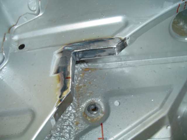
Posted by: East coaster Feb 17 2006, 07:57 PM
other side....
Attached image(s)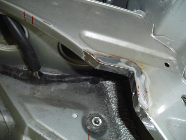
Posted by: East coaster Feb 17 2006, 08:00 PM
I'm using two isolator mounts from these areas to the front cooler flange and using one large isolator under the cooler. I needed to fab a bracket under the cooler for the isolator to mount to. I used a piece of the scrap I cut out of the fender well (outlets) and bent it up to provide a level mounting point under the cooler.
Pic:
Attached image(s)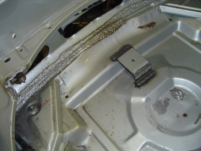
Posted by: East coaster Feb 17 2006, 08:03 PM
Used a piece of billet aluminum and made a mounting point for the cooler itself. Two recessed machine screws from each side of the cooler flange and the isolator threads into the chunk o' billet.
Attached image(s)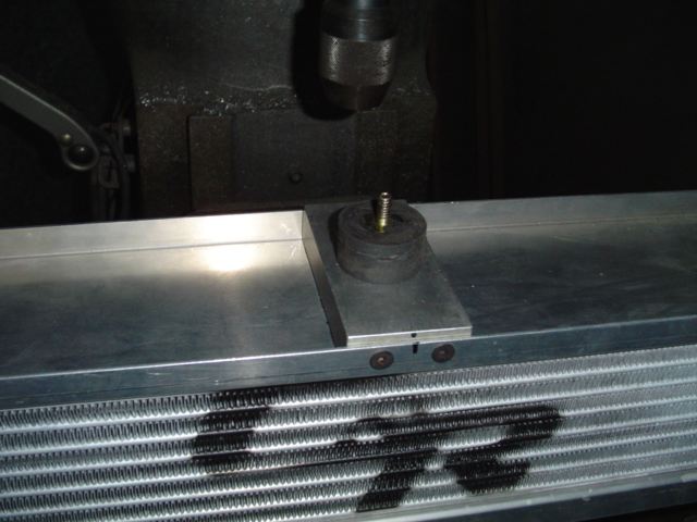
Posted by: East coaster Feb 17 2006, 08:04 PM
This is what it looks like fit up.....
Attached image(s)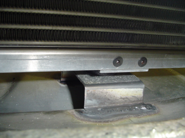
Posted by: East coaster Feb 17 2006, 08:06 PM
Once the mounting was squared away, it's on to the duct work. Started out with a rather large chuck of foam from a craft store.
Attached image(s)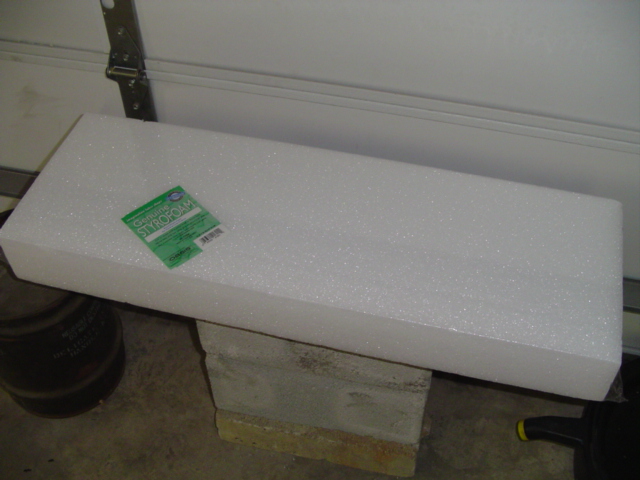
Posted by: East coaster Feb 17 2006, 08:07 PM
20 minutes with a hacksaw blade and some 36 grit, it started taking shape..........
Attached image(s)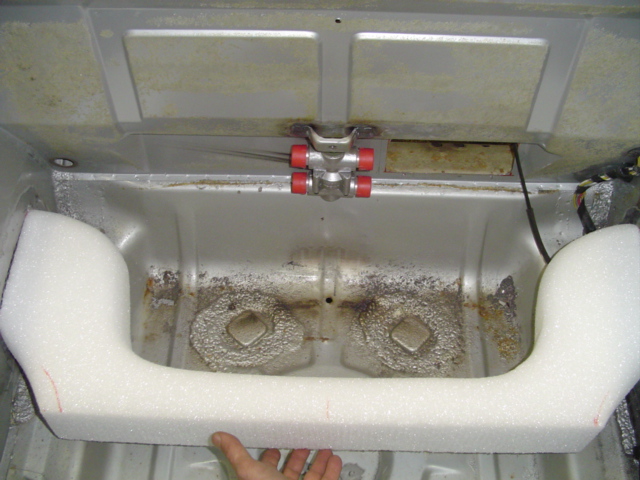
Posted by: East coaster Feb 17 2006, 08:10 PM
I had to hot glue an additional chunk to this one to get the size I needed. Then it was on to the front (or inlet) duct. Once again out come the blade and sand paper.
Attached image(s)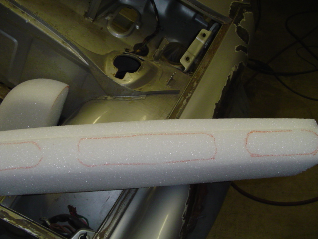
Posted by: Eric_Shea Feb 17 2006, 08:10 PM
Slick!
Posted by: East coaster Feb 17 2006, 08:11 PM
All shaping/fitting done and ready for disassembly and a day of fiberglassing.
Attached image(s)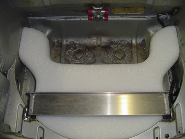
Posted by: East coaster Feb 17 2006, 08:12 PM
One mo'
Attached image(s)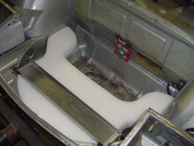
Posted by: Eric_Shea Feb 17 2006, 08:13 PM
Plans to lay a false floor on there?
Posted by: East coaster Feb 17 2006, 08:15 PM
You guys bored of the pics yet?
The foam pieces are just junk sacrificial plugs to be glassed over and then torn to pieces. I hope to get them glassed tomorrow, if so I'll post the final product pics. I plan to glass a flange around all the areas where the duct meets the cooler and the body for mouting/sealing purposes.
Posted by: East coaster Feb 17 2006, 08:17 PM
Yeah.....I want to be able to put the factory false floor back in (althought cut out around my space saver spare). I strived to keep everthing under the area for the floor board.
Posted by: Eric_Shea Feb 17 2006, 08:17 PM
Question/Concern:
With a GT shroud they made the exit hole twice as large as the input (expanded hot air outlet). Did you look into that?
That's a seriously trick install. 
Posted by: GTPatrick Feb 17 2006, 08:23 PM
Food for thought .  Why not somehow vent it out through the trunk lid infront of the windshield instead of into the wheel area ? Why add more heat to the tire/brake area . Wouldn't that be counter productive ?

At least through the top would give you a side benefit of having warm air possibly being blown onto the windshield acting like a defroster/defogger which in the colder climates would be a plus . 
The way you are doing this seems to be well thought out and a damn good idea in its own right. 

Posted by: East coaster Feb 17 2006, 08:25 PM
I have about 35 % larger outlet than inlet. I would've liked to get the magic 50%, but it would've been a stretch. I saw PMS using just 2 - 4" hoses for outlets and he swears he never gets overheating probs. The wheelwell is supposedly a better low pressure zone ( based on hearsay  )
)
I will be using 2 small (3.5 ") fans on the back side of the cooler just to safeguard against traffic jams. They will fit in the oulet plenum on the rear of the cooler. Maybe unnecessary, but easier now than later!
Posted by: Dave_Darling Feb 17 2006, 08:32 PM
| QUOTE (GTPatrick @ Feb 17 2006, 06:23 PM) |
| Why not somehow vent it out through the trunk lid infront of the windshield instead of into the wheel area ? |
The cowl area immediately in front of the windshield is a high-pressure area. Air won't flow to there very easily. The wheel wells are a low-pressure area, air will flow to there. The air coming out of the cooler is not going to be enough above ambient to make a big difference to the brakes, which see truly hellish temperatures at their "business end". When you're trying to cool something that's 950F, there's not much difference between using 80F air and (average) 90F air...
Near the front of the front hood could work, and might have the side benefit of giving you a little down-force. But that kills almost all of the front trunk for storage.
--DD
Posted by: McMark Feb 17 2006, 09:55 PM
I'm glad to see you're using GENUINE styrofoam. 
That's going to be one of the best oil cooler installs I've seen. I'm also fitting everything under the factory floor, but no spare. Either run-flat tires or AAA only.
Posted by: Eric_Shea Feb 17 2006, 10:10 PM
| QUOTE |
| but no spare |
Check above the thermostat. He's mounted the 'mount' there and a space-saver will sit upright.
Posted by: East coaster Feb 17 2006, 10:11 PM
Yeah, nothing but "genuine styrofoam" for me, no expense spared 
Posted by: East coaster Feb 17 2006, 10:16 PM
Yeah, I'm going with a space saver. I'm not sure how really useful it is, but I will have it.
Attached image(s)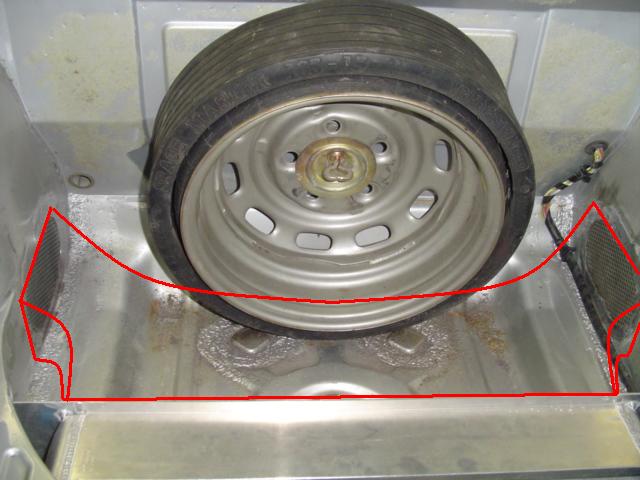
Posted by: Aaron Cox Feb 17 2006, 10:16 PM
copier! im cutting mine around the space saver also!!!! (But mine is a fuch  )
)
looks sweet, anyway you can make the exit any bigger? it is the only cooler for a 3.6, might as well make it super efficient....
Posted by: East coaster Feb 17 2006, 10:25 PM
Aaron, I probably could've squeezed a little (very little) more out of the exit area, but the real pinch point is here (red arrows). The exit holes are 4" x 8" and I couldn't get much more area than that in this pinch point. I needed to reserve some space sround this plenum to run my oil lines and still clear the spare.
Attached image(s)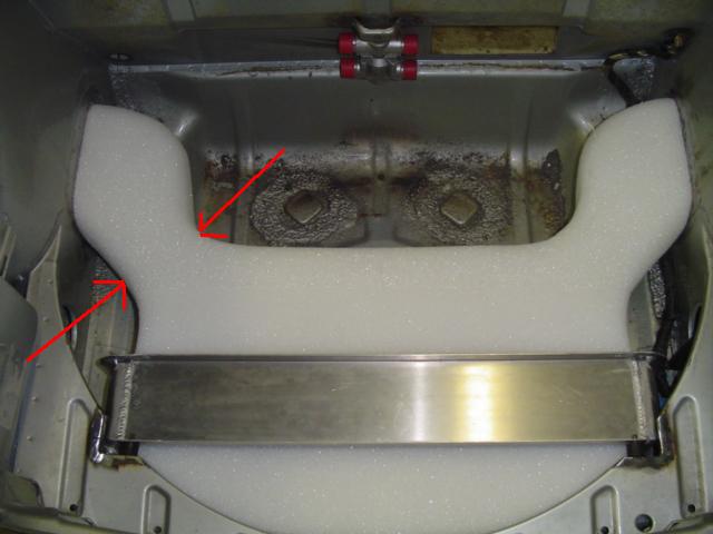
Posted by: trekkor Feb 17 2006, 10:34 PM
I like what you have done. Really nice concept.
KT
Posted by: VegasRacer Feb 17 2006, 11:37 PM
Very nice.
I am looking forward to your updates.
Posted by: jim_hoyland Feb 18 2006, 07:37 AM
Nice !! Keep the pictures coming.
Posted by: seanery Feb 18 2006, 07:51 AM
that's very clean...if it turns out to be effective after testing you should package up your parts for sale. I think I'd be interested, but I can't make schtuff out of FG.
Posted by: ArtechnikA Feb 18 2006, 07:52 AM
you're using a front-mounted -12 thermostat on a 3,6?
good luck with that...
Posted by: East coaster Feb 18 2006, 08:44 AM
Front mounted -12 cooler/thermo, yes, that was the plan.
Enlighten me on why that's a problem? This is going to be a street car if that has any bearing. I do have a -16 line from the oil tank to the engine. I've asked and researched this and have gotten many differing responses, mostly from people who are not running a 3.6 in a street car. So, I've resorted to taking advice from someone who has built a bunch of 3.6 cars, both street and track. I spoke to Jim Patrick (PMS) about my goals for this car and he convinced me -12 is the way to go.
I'm not discounting the concern you raise, I just would like to understand it? I've not run or even purchased the lines yet so, fill me in??
Posted by: East coaster Feb 18 2006, 09:08 PM
OK, it was a day of sniffin' fumes!
Layed up the main part of the plenum today. Started by adding scab plates to all the mounting surfaces. I used pieces of plexaglass for the flanges. These allow for a perfect flange when doing the layup.
A pic...........
Attached image(s)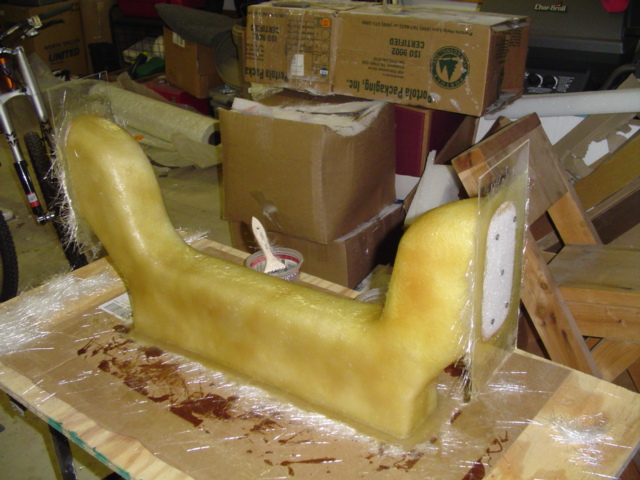
Posted by: Aaron Cox Feb 18 2006, 09:09 PM
3.6 likes -16/-20
Posted by: East coaster Feb 18 2006, 09:10 PM
Just used a couple of drywall screws into the foam to hold'em on.........
Attached image(s)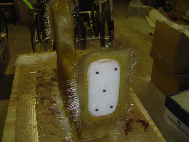
Posted by: East coaster Feb 18 2006, 09:12 PM
Did the layup, let it cure, and then shredded the styrofoam plug inside. It looks much less impressive in chunks.........Uh, turn your head and cough..... 
Attached image(s)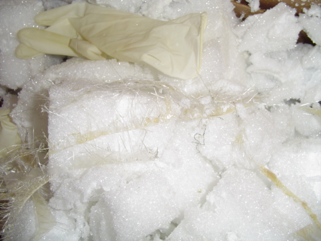
Posted by: East coaster Feb 18 2006, 09:13 PM
Here's the plenum after a quickie scrape and trim. Needs a little attention, but it's basically done.
Attached image(s)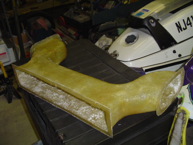
Posted by: East coaster Feb 18 2006, 09:14 PM
nuther.......
Attached image(s)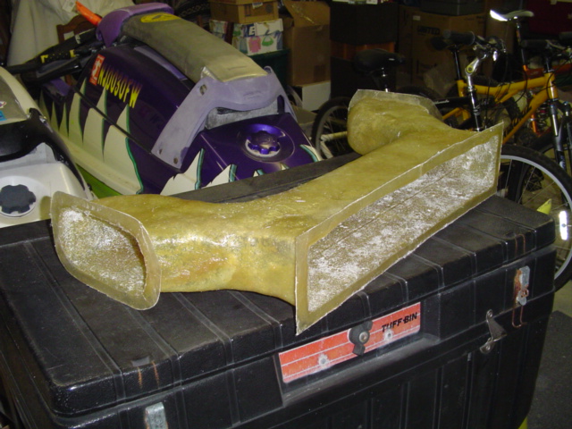
Posted by: East coaster Feb 18 2006, 09:15 PM
test fitting......
Attached image(s)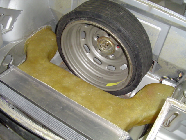
Posted by: East coaster Feb 18 2006, 09:16 PM
kjhgkjhgk
Attached image(s)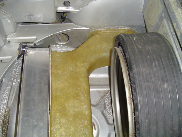
Posted by: East coaster Feb 18 2006, 09:18 PM
Here's tomorrow's project. It's the front plenum. I've added extensions (blue foam) to the plug to fit the finished part into the front cutouts. Here it sets ready for glass in the morning.
Attached image(s)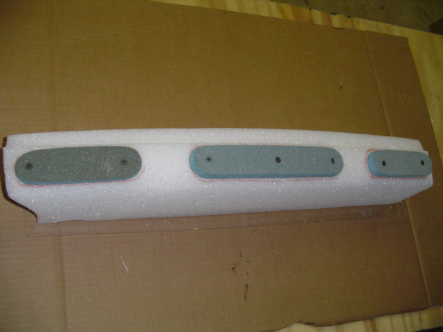
Posted by: J P Stein Feb 18 2006, 09:18 PM
Good job.
You've added to my general knowledge of how to do "stuff".
With any luck, I'll never have to do much FG work.....but shit happens, so ya never know. Getting the shittage out of the center looks like it's gonna be a messy job. Chemicals maybe?....heat?
(edit)
I was a bit quick on the trigger, eh.
Posted by: jim_hoyland Feb 18 2006, 10:10 PM
How many layers of glass did you use ? Any special weight or type ? Keep the pics coming, this is really interesting.
Posted by: jonwatts Feb 19 2006, 01:29 AM
| QUOTE (J P Stein @ Feb 18 2006, 07:18 PM) |
| You've added to my general knowledge of how to do "stuff". |
 very cool.
Hey Rich, I thought you sold your /6 and signed off a few months ago?
Posted by: ArtechnikA Feb 19 2006, 08:26 AM
| QUOTE (East coaster @ Feb 18 2006, 10:44 AM) |
| I spoke to Jim Patrick (PMS) about my goals for this car and he convinced me -12 is the way to go. I'm not discounting the concern you raise, I just would like to understand it? |
the 3,6 does flow a lot of oil. perhaps i'm just too conservative. if Jim Patrick is going to personally stand behind his recommendation, go with the experience.
but - IMO - the thermostat should be close to the engine. you're routing a lot of thick, cold oil all the way to the front of the car so it can be routed right back again. since heat is radiated from the lines, it could even take longer to reach operating temperature. (enough longer to make any practical difference? maybe not. i'll be glad to admit i don't know. where does Porsche mount the thermostat in the 3,6 911's ?)
it's your car, do what you want and think best. the reality is that Porsche engines are usually pretty robust and lots of approaches that appear marginal work well enough.
Posted by: ArtechnikA Feb 19 2006, 08:46 AM
| QUOTE (jonwatts @ Feb 19 2006, 03:29 AM) |
| Hey Rich, I thought you sold your /6 and signed off a few months ago? |

i did sell the car and it still hurts to think about it.
i unsubscribed from just about every topic i was following.
i still get new topic notifications but i actually read very, very few new threads - most of those i do look at have /6 content -- i still have the 911 and it will be getting a lot of attention this year - including a new engine and front oil cooler.
with the new job, its 3-hr (total) commute, more limited email/internet access, and increased responsibilities, i just can't be nearly as active as i was.
so if you're asking me why i don't stay away, i can arange it...
Posted by: J P Stein Feb 19 2006, 09:04 AM
Rich:
Generally, you and I are are in agreement about most stuff.
I wouldn't mount a thremo up front unless my oil tank was up there (maybe, I'd have to think on it for a bit) and I would use a AN16 line minimum with a 3.6L.....but I've given up preaching to guys that have already made their choices. If pressed, I'll say "lemmeno how that works out".
As for the "to be or not to be" (in the 914club sense), face it
you need the fix....unlike me, I have nuthin' better to do.
Posted by: drew365 Feb 19 2006, 09:37 AM
| QUOTE (Dave_Darling @ Feb 17 2006, 07:32 PM) | ||
The cowl area immediately in front of the windshield is a high-pressure area. Air won't flow to there very easily. The wheel wells are a low-pressure area, air will flow to there. The air coming out of the cooler is not going to be enough above ambient to make a big difference to the brakes, which see truly hellish temperatures at their "business end". When you're trying to cool something that's 950F, there's not much difference between using 80F air and (average) 90F air... Near the front of the front hood could work, and might have the side benefit of giving you a little down-force. But that kills almost all of the front trunk for storage. --DD |
Dave; do you think adding a scoop over the cowl vent with the opening facing the windshield, would create enough low pressure to vent out of the trunk? My cooler currently dumps the air under the car and I want to change that without cutting up my hood if possible.
Posted by: Dave_Darling Feb 19 2006, 10:33 AM
| QUOTE (drew365 @ Feb 19 2006, 07:37 AM) |
| Dave; do you think adding a scoop over the cowl vent with the opening facing the windshield, would create enough low pressure to vent out of the trunk? My cooler currently dumps the air under the car and I want to change that without cutting up my hood if possible. |
Only if you cut off your windshield...

The WS is what creates the high-pressure area, so it seems unlikely that just making a deflector on the front of the opening would do much. It would be interesting to find out for certain, though! If you can find a pressure-testing rig you might be able to find out. If you do, please let us know.
--DD
Posted by: East coaster Feb 19 2006, 11:54 AM
As far as thermostat placement, there seems to be 2 schools of thought.
One says place the thermo near the engine so as to prevent having to pump cold oil to the front and back needlessly.
Second says place the thermo near the cooler to protect the cooler from the pressures created by all that cold oil in the lines (if thermo was at rear).
I read about a bazillion threads on this and it seems there's no real answer. I definitely could not find any answer backed up with data. I've seen more installs with the thermo up front than in the rear and I've not heard any horror stories yet. I think a coin toss (heads up front, tails in rear) is as scientific an approach as I've seen so far.
JP - As far as the -12 vs -16 lines thingy. I've not made up my mind yet. I could easily change the plan at this point, I'm just looking for information on why? If -16 is necessary I would certainly go that route, but no one has backed up that claim with any info? I'm all ears and open to any suggestions.
Posted by: Eric_Shea Feb 19 2006, 01:02 PM
Begin Parrot: Squawwwwk
Porsche 911 Performance Handbook, Second Edition, Author - Bruce Anderson, Page 189, End of Second Paragraph:
The connecting hoses for this application should be -12 or larger to prevent restricing the oil flow to and from the cooler back to the tank.
(discussing the addition of a large radiator type cooler for track applications)
Off Parrot: Squawwwwk
He knows more than me.
Posted by: Aaron Cox Feb 19 2006, 01:05 PM
| QUOTE (Eric_Shea @ Feb 19 2006, 12:02 PM) |
| Begin Parrot: Bawwwwwwk Porsche 911 Performance Handbook, Second Edition, Author - Bruce Anderson, Page 189, End of Second Paragraph: The connecting hoses for this application should be -12 or larger to prevent restricing the oil flow to and from the cooler back to the tank. (discussing the addition of a large radiator type cooler for track applications) Off Parrot: Bawwwwwwk He knows more than me. |
its common practice to run -16 and -20 on a 3.6......
will -12 hurt? dunno, prolly not
Posted by: Eric_Shea Feb 19 2006, 01:10 PM
He starts that paragraph with:
'With any of the larger displacement, high-power output, normally aspirated engines or turbocharged engines...'
Posted by: race914 Feb 19 2006, 01:12 PM
| QUOTE (Eric_Shea @ Feb 19 2006, 11:02 AM) |
| Begin Parrot: Bawwwwwwk Porsche 911 Performance Handbook, Second Edition, Author - Bruce Anderson, Page 189, End of Second Paragraph: The connecting hoses for this application should be -12 or larger to prevent restricing the oil flow to and from the cooler back to the tank. (discussing the addition of a large radiator type cooler for track applications) Off Parrot: Bawwwwwwk He knows more than me. |
Hey Eric,
You may have earned a new avatar!
Greg
Attached thumbnail(s)

Posted by: Eric_Shea Feb 19 2006, 01:12 PM
Now... if I was running the 'tank' up front, that would be a different story.
Posted by: Eric_Shea Feb 19 2006, 01:13 PM
I was looking for a birdie avatar... we need one.
Posted by: Aaron Cox Feb 19 2006, 01:14 PM
i thought parrots squawked and chickens bawked?
Posted by: trekkor Feb 19 2006, 01:16 PM
I believe the common misunderstanding is that the line coming from the front cooler is going right back into the motor like on a FOUR. Under pressure.
Well it doesn't. It fills the oil tank. This is not a starvation or oil pressure drop issue.
The -16 oil line from the oil tank to the motor is what is needed.
Remember, the oil level is checked with the motor warm and running. That's oil in the lines, motor and 8-12+ qts, depending on what tank you are using.
KT
Posted by: Eric_Shea Feb 19 2006, 01:17 PM
| QUOTE |
| i thought parrots squawked and chickens bawked? |
Thanks for that... changed
And what's this 'common practice' crap. Stop stroking your roll and go work on your car. Trek brings it back on topic!
Posted by: db9146 Feb 19 2006, 01:39 PM
East Coaster, I like it...a lot. Great job. Keep the pics coming.
Thanks for sharing.
Posted by: J P Stein Feb 19 2006, 07:07 PM
Anderson says quite a lot.
He says the 964/993 oil pump moves 67 liters per minute
on the pressure side & 1.8 times that much on the scavenge side. I can't remember the exact specifics on the 76-88 pump
but I think it was in the mid 50s per minute on the pressure side.
He also talks about restrictions in the Aux cooler side causing
the oil pump fail. Too small lines & restrictive oil coolers, yada.
The scavenge side is unregulated...pressure wise. Restrictions
or cold oil cause the pump to work harder.....it is almost a positive displacement pump, me thinks. As restrictions rise, it just keeps pumping
its 67 liters by raising the pressure. When that gets beyond its capabilities, it cavatates. The voids caused by the cavatation can allow the gears
to become exposed to each other...not to mention the drive shaft shocks. Bad shit.
If you have an aux thermostat with a pressure relief valve, the oil can by pass the cooler & be pushed thru the filter (with it's own pressure relief valve) into the tank.....no harm , no foul.
If you don't have either of these safety features (cheep filter & thermo)in your scavenge loop, that's your problem, not mine.
I'm done with this subject....move along, nothing to see here folks.
Posted by: East coaster Feb 19 2006, 08:23 PM
Ok..........more fumes, more itchy scratchy, but a little more progress!
Here's the front inlet plenum after lay up and evacuation of the plug foam: I shaped it to fill the void between the front of the cooler and three intake holes. The three oval extensions actually fit into the holes on the front of the car.
Attached image(s)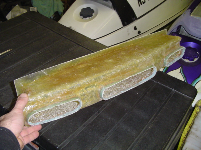
Posted by: East coaster Feb 19 2006, 08:24 PM
mnbvmnbv
Attached image(s)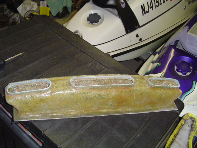
Posted by: East coaster Feb 19 2006, 08:27 PM
Here's the first test fit. I does need a little trimming and sanding here and there, but it basically went right in and fits. I plan to add adhesive foam trim around the inlet openings when it gets installed for real.
Attached image(s)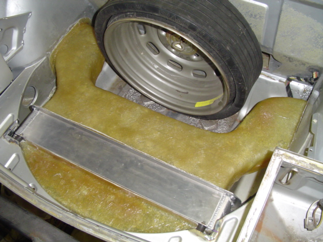
Posted by: East coaster Feb 19 2006, 08:28 PM
Here's looking into the business end of the cooler intake:
Attached image(s)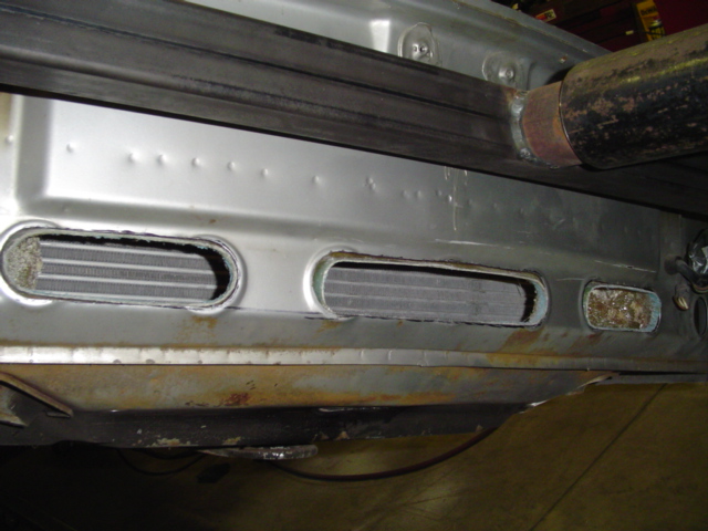
Posted by: ArtechnikA Feb 19 2006, 08:28 PM
| QUOTE (Eric_Shea @ Feb 19 2006, 03:02 PM) |
| Porsche 911 Performance Handbook, Second Edition, Author - Bruce Anderson, Page 189, End of Second Paragraph: The connecting hoses for this application should be -12 or larger to prevent restricing the oil flow to and from the cooler back to the tank. (discussing the addition of a large radiator type cooler for track applications) |
...but if you ask him in person he'll say they shouldda said -16 in the book. at least that's what he said when i asked him...
Posted by: East coaster Feb 19 2006, 08:29 PM
last pic.
Attached image(s)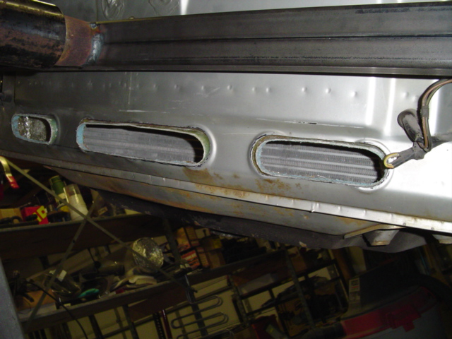
Posted by: East coaster Feb 19 2006, 08:33 PM
Ok.........so if you use -16 lines, do you need to use a -16 cooler and -16 thermo or is the idea simply to reduce restriction for the long paths from front to rear???
Anybody know what the stock 964 uses to run from front to rear?? If so, how does the factory sizing compare to -12 and -16??
Posted by: Eric_Shea Feb 19 2006, 08:34 PM
| QUOTE |
| ...but if you ask him in person he'll say they shouldda said -16 in the book. at least that's what he said when i asked him... |
He told me -8...
Posted by: East coaster Feb 19 2006, 08:38 PM
while we're on a oil line kick, does anyone have any preferences on the actual line itself?
Aeroquip, Russell, Earls, don't care, doesn't matter?????
Posted by: Aaron Cox Feb 19 2006, 08:38 PM
| QUOTE (East coaster @ Feb 19 2006, 07:38 PM) |
| while we're on a oil line kick, does anyone have any preferences on the actual lines itself? Aeorquip, Russell, Earls, don't care, doesn't matter????? |
XRP goes together easier than earls.....
Posted by: 9146986 Feb 19 2006, 08:44 PM
I guess I don't understand mounting the thermostat up front. One of the reasons for a thermostat is to keep from pushing cold oil all the way to the front of the car.
I know the Mocal t-stats let some oil flow through the cooling circuit, but why not mount the thermostat nearer the engine?
Just a question.
Posted by: Aaron Cox Feb 19 2006, 08:45 PM
| QUOTE (9146986 @ Feb 19 2006, 07:44 PM) |
| I guess I don't understand mounting the thermostat up front. One of the reasons for a thermostat is to keep from pushing cold oil all the way to the front of the car. I know the Mocal t-stats let some oil flow through the cooling circuit, but why not mount the thermostat nearer the engine? Just a question. |
makes the most sense to me
taht being said, mine is near my motor
Posted by: trekkor Feb 19 2006, 09:28 PM
I don't beat on my car until it's hot, so none of this really matters.
KT
Posted by: Aaron Cox Feb 19 2006, 09:47 PM
| QUOTE (trekkor @ Feb 19 2006, 08:28 PM) |
| I don't beat on my car until it's hot, so none of this really matters. KT |
thats a relativists statement....

Posted by: McMark Feb 19 2006, 09:51 PM
I'm going -12 on mine, and last I heard SirAndy is as well in his. I'll be putting the thermostat in the engine bay just like I did on the race car I did some work on. I guess we'll see how it works out.
Posted by: Eric_Shea Feb 19 2006, 09:53 PM
JD... you're one scary dude!
Posted by: race914 Feb 20 2006, 06:59 PM
| QUOTE (Aaron Cox @ Feb 19 2006, 06:38 PM) | ||
XRP goes together easier than earls..... |
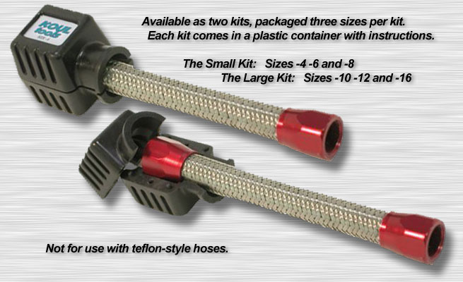
Regarding assembly, just came across http://www.koultools.com/ While ordering Aeroquip hose on http://www.racerpartswholesale.com/
Attached image(s)
Posted by: maf914 Feb 21 2006, 10:30 AM
Eastcoaster,
Do you use a mold release on the styrofoam plug before laying up the fiberglass? Or do you lay it up directly on dry foam? 
Thanks for posting this process. Your installation looks great.
Posted by: Series9 Feb 21 2006, 11:09 AM
Absolutely beautiful. Makes my front trunk look like a mess.
I'm running -12 on the scavenge and -16 on the supply. No problem.
Posted by: rick 918-S Feb 21 2006, 11:13 AM
Very nice!
Posted by: Headrage Feb 21 2006, 11:21 AM
You're gonna make more of these to sell right?
Posted by: mrdezyne Feb 21 2006, 11:34 AM
| QUOTE (maf914 @ Feb 21 2006, 08:30 AM) |
| Eastcoaster, Do you use a mold release on the styrofoam plug before laying up the fiberglass? Or do you lay it up directly on dry foam? Thanks for posting this process. Your installation looks great. |
I was wondering the same thing. Looks like its directly on the foam since he had to cut away the core once it was cured. I've heard of wraping your core in aluminum foil and glassing on top of that before, just FYI...
Posted by: URY914 Feb 21 2006, 11:44 AM
Wrapping the plug with something does help when it comes to pulling the plug out. I used wide clear shipping tape because f/g won't stick to it and it leaves a nice smooth finish on the 'glass.
I'm not going to say anything about the line size, but that glass work it top notch
P
Posted by: spunone Feb 21 2006, 11:52 AM
Line size ?? if the pump holes are 3/8 inch won't an8 work just as well it's same id ?? Just askin
Posted by: Dr Evil Feb 21 2006, 12:20 PM
Just freaking cool! I know how to FG, but I never thought to attempt what you did with such success. Nice
What resin did you use?
Trekkor,
Are you using an oil cooler on a 2.7?
Posted by: East coaster Feb 21 2006, 12:22 PM
I layed up the glass right over the foam. I did a small test piece first and the impact was minimial, so I decided to go that route. I had planned on sealing the foam plug prior to lay up, but then said screw it. This was intended to be a "one off" sacrificial plug with no intent on producing more than one finished part. With that said, sorry to those who've asked, but there's no plan to produce these parts.
I did hope by posting these pics that someone could make these or any fiberglass parts they desired in the same sort of fashion. The whole process took 3 days of part time work. It's not really that difficult....Really! It's more like a third grade paste and glue project. People on this site have "mad" skills and this is an easy project. It requires no special tools (hacksaw blade, razorblade, paint brush, sand paper) and about 30 bucks in materials.
Most of my previous experience has been with more "finished" parts, where the plug is created and worked to a near perfect finish and then a female mold is created. The female mold is then used to create the actual part. This requires more work upfront, but lots less work on the tail end of the process and allows multiple pieces to be produced. This was actually the first sacrificial piece I ever made.
The plug could've been sealed with bondo, drywall joint compound, clay or any number of things to make the plug more finished and help to protect it during layup. I actually like the idea of the clear packing tape or aluminum tape (real duct tape). I've used both in other fiberglass project and they work great and are simple to deal with.
Posted by: maf914 Feb 21 2006, 12:23 PM
| QUOTE (URY914 @ Feb 21 2006, 09:44 AM) |
| but that glass work it top notch |
It does look good. It reminds me of the exposed bare fiberglass in the old Porsche race cars like the 908 and 917. Bare fiberglass ducts, engine shrouds, cooling fan, intake horns.... Cool!
Now everything is black carbon fiber. That's okay, too.

Posted by: tdgray Feb 21 2006, 12:25 PM
Top Notch work my man 
Posted by: fiid Feb 21 2006, 01:50 PM
The glasswork looks awesome!! Great job.
I do have to ask a stupid question though:
How come it's okay (encouraged?) to use braided oil lines and not brake lines? Is it just because the breaklines have to flex with every bump in the road? What makes this so different?
Thanks for the education 
Posted by: Dr Evil Feb 21 2006, 02:58 PM
I have not heard that you shouldn't use braded brake lines, I have heard that you shouldn't use braded anywhere wher you can not inspect it often as it is like a slow moving file. If you use braded oil line it is possible to have it rub through things in tunnels and such, but if you have it properly immobilized it should be a non issue.
AFAIK, braded brake lines are better (stiffer). I have them, but then again I only use the parking brake....since it is on jack stands 
Posted by: ArtechnikA Feb 22 2006, 06:43 AM
| QUOTE (fiid @ Feb 21 2006, 03:50 PM) |
| How come it's okay (encouraged?) to use braided oil lines and not brake lines? Is it just because the brakelines have to flex with every bump in the road? What makes this so different? |
the types of hose and their fittings are *completely* different, although they do both have an exterior woven stainless steel wire braid sheath.
the lines commonly used for fluid transfer (oil and fuel) are a nitrile rubber inner hose with various layers of reinforcement until you get out to the final outer braided sheath. most hose ends for this type of hose use a cutter to split the rubber hose (annular) and form a positive, high-retention seal.
brake (and clutch, where it's used) is a Teflon inner hose with a single braided stainless sheath. the hose end is completely different and may in some cases separate from the hose. could be manufacturing defect, could be installation defect, could be abuse. but it *has* happened.
in addition, non-DOT-rated hose has no outer nonpermeable sheath, so sand and grit can theoretically penetrate the braid and exacerbate abrasion of the Teflon inner tube. Teflon doesn't like to be kinked, os if that ever happens, for any reason, you should consider the hose toast. hanging a caliper from the brake hose is an especially bad thing.
many consider them an expensive, high-risk item with marginal to imperceptible gain. aircraft use them, and race cars use them. aircraft are *completely* inspected by certified inspectors at least annually. race cars, if they last longer than a season, are at least inspected and usually rebuilt and replumbed *very* frequently. and they DO NOT use adapter fittings like we do - they are AN-3 all the way from the MC to the caliper...
i plan to use DOT-rated lines on my car, as I have had good results with them in the past and i'm committed to a regular inspection program.
the technical differences between nitrile and Teflon hose are very well spelled out on the Earls site - and probably Aeroquip and Goodridge and everybody else that makes hose. Hose ends for Teflon braided-steel lines are *very* expensive...
Still - when i replumb the 911's fuel system, i plan to do it in braided Teflon hose, because there are so many oxygenates in contemporary fuels that I do not trust nitrile in this application any more for cars that are not subject to re-plumbing on a regular basis. it will cost a small fortune but i will be done with it once and for all...
Posted by: Dr. Roger Feb 24 2006, 07:40 PM
how on earth did i miss this thread??? very classy solution.
i'm thinking a similar FG thing for my radiator on a V8 car. i already have a space saver tire but want to put more stuff up front if possible.
by any chance do you know how high the temperature can go on the FG?
Posted by: trekkor Feb 24 2006, 11:22 PM
| QUOTE (Dr Evil @ Feb 21 2006, 10:20 AM) |
| Trekkor, Are you using an oil cooler on a 2.7? |
I run a 2.0 with a *BIG* Setrab cooler.
KT
Posted by: East coaster Feb 25 2006, 07:26 AM
Roger, Fiberglass would have no problem dealing with radiator range of temps.
Posted by: davep Feb 25 2006, 10:07 AM
Since I deal with heat exchange, air and fluid flow as part of my job, I thought I'd add just a little bit here.
Heat exchangers depend on velocity of the air as much as volume to do the job efficiently. A car at speed with the HX fully exposed will see sufficient velocity. At rest there, obviously, is no velocity. As you restrict the inlet, both volume and velocity decrease. Similarly, on the outlet side any restrictions will reduce volume and velocity. Pressure differences will also have a significant effect on both.
One way of designing a system is to start by measuring the cross-sectional area of the heat exchanger. By rights you should consider only the open area of the rad, that area through which the air actually flows, and of course that means subtracting the area of the tubes. So, if you have a 4" x 20" rad for a total area of 80 sq inches you may find the open area to be 40 to 50 sq inches. Then you can plan the inlet area to be at least this size, and slightly larger if there are lots of sharp edges as opposed to a nicely contoured duct. Generally the inlet is very short and unrestricted. On the outlet side of the rad, paths tend to be a little longer and may not be straight, thus the cross-sectional area of the outlet is generally larger than the inlet. The rule of thumb however is to try to keep the duct cross-section constant even while it is changing shape. The idea is to try to keep the velocity constant. Sharp bends should be avoided.
Placing booster fans in the system can be a real problem. When the car is at rest, and there is no other airflow, then they become a necessity. At speed they are usually a restriction. In this particular design I'd place the two fans in front of the rad and between the ducts in the front; you have three duct opennings, and two spaces between the duct opennings. By placing the fans out of the direct incoming airflow you reduce the restriction to airflow at speed, yet at rest the fans will easily draw air from the opennings on either side of it. I'd place the fans directly on the rad itself. My choice of fans for this would be a pair of 120mm x 38mm high speed units with ball bearings. I have some Panasonic models of this type.
Similar to the airflow design, the oil lines and other parts should be matched. It would be useless, almost, to have -16 lines and a -8 openning into the rad or into the thermostat. I too would place the thermostat close to the engine. I might even have two thermostats, one at the engine and the other at the rad. If the rad does not have a pressure relief valve in it, or with it, then the second thermostat would help. This would stage the cooling, and allow faster engine warmup. It may also prevent over-cooling of the oil on cool days. My friend with the GT always warmed the car up to ensure the hot oil was flowing through the rad before taking the car onto the track. Too many of his friends blew their rads halfway around on the first lap because they did not warm things up properly. He suggests synthetic oil to reduce the problems.
Your system sure is elegant, and that is a good sign. Perhaps this thread should be in the Classics section soon.
Powered by Invision Power Board (http://www.invisionboard.com)
© Invision Power Services (http://www.invisionpower.com)