Printable Version of Topic
Click here to view this topic in its original format
914World.com _ 914World Garage _ Megasquirt Update
Posted by: yarin Mar 28 2006, 09:37 PM
I Was about to dig up my old thread from two months ago... but I felt some of these pics deserve there own thread.
I'm really moving along on my upgrade from carbs to MS. I should be able to power up the system this weekend and crank it the following weekend.
I chose a rather different approach to my install, a combination of logic, simplicity and durability. Please give me your input. For those who aren't familiar with MS go to www.megasquirt.info and www.msefi.com (forums).
I bought all of my Megasquirt parts from DIYautotune.com. Excellent vendor, i suggest doing business with them for anything.
What's left:
finish db-37 connector
connect all wires in relay box
mount intake plenum, connect DIY PVC intake
install gas tank
checked double check and triple check all fuel connections and wiring
configure MS
crank!!
Here are pics:
Attached image(s)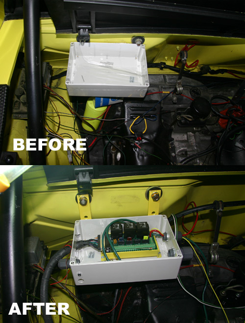
Posted by: yarin Mar 28 2006, 09:38 PM
aint it purty? 
Attached image(s)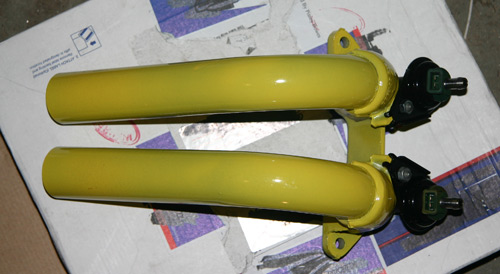
Posted by: yarin Mar 28 2006, 09:39 PM
 i like it
Ok i'll admit it.. the injector connectors do need the outer plastic housing trimmed to fit properly on the injectors. not plug and play, but it should be a solid connection once some material is removed.
All parts sand blasted and powder coated by ME. 
Attached image(s)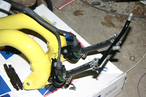
Posted by: yarin Mar 28 2006, 09:40 PM
db-37, i went the crimp route instead of the kit solder cup.
Attached image(s)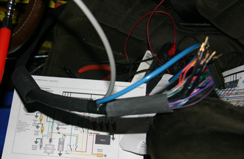
Posted by: yarin Mar 28 2006, 09:41 PM
Rumor has it the DB37 connections are the biggest design issue with megasquirt.
Attached image(s)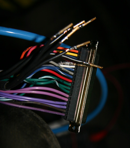
Posted by: yarin Mar 28 2006, 09:41 PM
soon to be off jacks.
Attached image(s)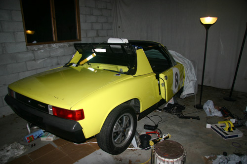
Posted by: newto914s Mar 28 2006, 11:35 PM
way to go yarin 
I like the look of the powder coated fuel rails. Very slick!
Samson
Posted by: fiid Mar 29 2006, 12:37 AM
Looks clean - very nice work... good job!
Posted by: brokenmoped Mar 29 2006, 12:46 AM
What happened to the panasports?
Posted by: jkeyzer Mar 29 2006, 03:22 AM
What gauge wire is used for the DB-37 connections? Is that a kit?
And I can't tell from the photo, but are the crimp terminals actually soldered to the wire?
I am building my own Megasquirt system as well. I am not using the relay board approach however, my harness will go straight into the ECU box in the car.
Posted by: yarin Mar 29 2006, 05:40 AM
| QUOTE (brokenmoped @ Mar 28 2006, 10:46 PM) |
| What happened to the panasports? |
I have two sets of panasports with race tires. I bought a crappy street set to drive around the street for dirt cheap.
Don't worry, i'm holding onto those panasports with my life

Posted by: yarin Mar 29 2006, 05:46 AM
| QUOTE (jkeyzer @ Mar 29 2006, 01:22 AM) |
| What gauge wire is used for the DB-37 connections? Is that a kit? And I can't tell from the photo, but are the crimp terminals actually soldered to the wire? I am building my own Megasquirt system as well. I am not using the relay board approach however, my harness will go straight into the ECU box in the car. |
I bought the relay cable kit from DIYautotune. I would highly recommend that everyone building a MS kit does the same, even if you aren't using a relay box.
They kit comes with one end terminated and the parts to solder a db-37 connector on. In your case just chuck the db-37 parts, they dont cost anything anyway.
The wiring in the DIYautotune harness is automotive grade 20AWG with the exception of the grounds and injector wires which are 14AWG. The ignition wire is shielded with a 20AWG core. The 14AWG wires breakout into 20AWG at the DB37 end. Internal to the cable there is some sort of junction to go from 1 14ga to 3 20ga in the case of the grounds. I did the same on the side that I terminated.
The photo you are looking at is the side that I crimped. The wire I used for the grounds and injector wires is 18ga, probably a little too heavy for the crimp. So I added a touch of solder as a safety. If I had to do it again I would have used standard 20ga wire. Yes I had proper tooling to crimp these connectors on. It aint cheap to purchase.
Posted by: mikelsr Mar 29 2006, 05:57 AM
Why did you elect to crimp rather than solder?
Posted by: yarin Mar 29 2006, 07:32 AM
| QUOTE (mikelsr @ Mar 29 2006, 03:57 AM) |
| Why did you elect to crimp rather than solder? |
I chose crimp over solder cup for a number of reasons. Everyone has their own, here are mine.

These are the sockets used in a crimp style SubD connector. Digikey p/n A1009-ND. It accepts 20-24AWG insulated wire.
Vibration and stress can lead to premature failure of both types of connections. A solder joint is a hard junction with no cable relief. The insulation is there to insulate the wire.
In a crimp style connection the crimp acts as a strain relief crimping onto the insulation. The electrical pin/wire connection is now subject to reduced mechanical stress.
The whole purpose of using stranded wire in applications like this is to increase durability and resistance to breakage. By soldering stranded wire, you now have solid wire. Bend both types of wires back and forth 50 times and see which breaks first.
That's just my opinion. Soldering is the easiest and cheapest method, but least reliable in my eyes. That's why all non-PCB mounted cable type connectors are crimp style.
Posted by: kconway Mar 29 2006, 08:10 AM
Why not put a backshell on that db-37 connector to provide the strain relief? That type of crimp contact does not provide for a "cold weld" of the wire to the contact and is no where near the same in contact resistance to a soldered contact. Just .02 worth...
Posted by: bd1308 Mar 29 2006, 08:28 AM
fill the DB37 cable with epoxy when you're set?
Thats what I'm going to do.
b
Posted by: DNHunt Mar 29 2006, 08:35 AM
Britt
Epoxy takes care of some of the problems but MS appeals to tinkerers like me and you'll want to change it. I suppose you could leave the cable extra long and wack off a chunk and put a new DB 37 on each time you change functions. The DB 37 is just a bad connector in this application.
Dave
Posted by: bd1308 Mar 29 2006, 08:48 AM
this is true. I am planning to install MS during the summer.
b
Posted by: DNHunt Mar 29 2006, 09:05 AM
Try to design in fudge factor wherever you can so you can fool with it, because some new feature will require a rewire and you'll want to take advantage of it with out ripping the whole thing out. Extra length on cabling is good. Extra conductors in the cable are good. While a lot of people don't like screw terminals I put some screw terminal strips in my relay box and ran extra inputs and outputs through there so I can reconfigure the FI harness easily. No problems so far but, I do check them every once in a while.
Dave
Posted by: jkeyzer Mar 29 2006, 10:50 AM
I think typical crimp pins for a DB-37 are designed for 24-30 gauge wire. I have had a really hard time getting a good crimped connection to a 20 gauge wire (the wire is too fat, and my crimp tool is mediocre) so I will probably end up touching them with solder as well. The downside is that often this causes the insulation to shrink back and fail to reach the strain relief built into the pin. I am hoping that one of these days I can find a system of pins/crimper that works for 18-20 gauge wire, but I think your method should work well also.
Posted by: lapuwali Mar 29 2006, 11:50 AM
The DB-37 is simply the wrong part for the job. The newer Microsquirt uses the AMPSeal connectors, which are a far better part for this use.
I haven't decided exactly on the course I'll follow, yet. What's settled is I won't be using the MS case, but another, larger case. The through connector for that case will be a circular plastic multi-pin connector from DigiKey. This is available with a variety of pin sizes, including 18g - 20g, and each pin can carry 19A. I'll either connect this to the MS board by direct soldering of the wires to the board (no DB-37 connector at all), or by using a short cable with a DB37 on one end. This cable would be clamped into place, so vibration shouldn't be too big an issue, so a solder cup connector may be used (mostly because I have them already).
I intend to be lazy and just buy a v3.0 board pre-assembled from DIY or RS-Autosport, in which case I'll probably go the DB-37 route, only to save myself the hassle of de-soldering the DB-37 from the board first.
I'm also NOT going to be using the zillion ground wires run through the DB-37 all the way out to the main connector, but will be joining them to one screw post inside the big case, which will then run to a single 14g ground wire to be run to the big case (metal, so it should provide shielding) and then to the engine case.
The MS board will be mounted via rubber mounts inside the large case.
Right now, the "large case" is most likely to be a gutted D-Jet ECU case. Lots of room in there, and it seems to be adequately water resistant.
Posted by: toon1 Mar 29 2006, 12:09 PM
| QUOTE (lapuwali @ Mar 29 2006, 09:50 AM) |
| The DB-37 is simply the wrong part for the job. The newer Microsquirt uses the AMPSeal connectors, which are a far better part for this use. I haven't decided exactly on the course I'll follow, yet. What's settled is I won't be using the MS case, but another, larger case. The through connector for that case will be a circular plastic multi-pin connector from DigiKey. This is available with a variety of pin sizes, including 18g - 20g, and each pin can carry 19A. I'll either connect this to the MS board by direct soldering of the wires to the board (no DB-37 connector at all), or by using a short cable with a DB37 on one end. This cable would be clamped into place, so vibration shouldn't be too big an issue, so a solder cup connector may be used (mostly because I have them already). I intend to be lazy and just buy a v3.0 board pre-assembled from DIY or RS-Autosport, in which case I'll probably go the DB-37 route, only to save myself the hassle of de-soldering the DB-37 from the board first. I'm also NOT going to be using the zillion ground wires run through the DB-37 all the way out to the main connector, but will be joining them to one screw post inside the big case, which will then run to a single 14g ground wire to be run to the big case (metal, so it should provide shielding) and then to the engine case. The MS board will be mounted via rubber mounts inside the large case. Right now, the "large case" is most likely to be a gutted D-Jet ECU case. Lots of room in there, and it seems to be adequately water resistant. |
While thinking about doing this myself I also had the same idea of putting everything in the d-jet case. Hey why not there is a mount there, there is lots of room for both boards and noextra labor in running the wiring through the F/W.
I was also thinking you could probably insulate the rest of the box with foam from vibration and heat.
Posted by: yarin Mar 29 2006, 12:11 PM
In the event that I need to rewire a DB-37 connector or a pin pulls out I dont want to have to cut off the entire connector as would be the case if i filled the shell with epoxy.
I have a nice solid AMP metal shell for the connector which adds a level of strain relief.
My relay box is a Hammond 1554V2GYCL Enclosure with a clear polycarbonate watertight light. Too bad they don't make it in black. However I did punch a hole in the side of the box for the relay cable to pass through. So no it is no longer water tight, but it is water resistant to a certain degree. If I had to do it again I would have purchased a panel mount heavy duty connector from digikey and hard wire it to the relay box. If I have connection problems on the relay box side that is going to be my solution.
I used rubber grommets between the relay box and the mounting brackets. It floats nicely. Same thing goes for the megasquirt brain. 
Crimping 20ga wire isn't a problem if you have the right tooling. Its expensive ($100+), but I know its done right. The comforting parts about the use of a DB-37 connector is the parallel injector and ground lines. If one pin breaks you won't know it assuming the remaining pin(s) can handle the current draw.
Posted by: jsteele22 Mar 29 2006, 12:46 PM
| QUOTE (lapuwali @ Mar 29 2006, 10:50 AM) |
I'm also NOT going to be using the zillion ground wires run through the DB-37 all the way out to the main connector, but will be joining them to one screw post inside the big case, which will then run to a single 14g ground wire to be run to the big case (metal, so it should provide shielding) and then to the engine case. |
A zillion might be a few too many, but you definitely don't want to skimp on ground wires in the main cable. For purely DC currents, it really doesn't matter where the ground current runs, as long as it makes it where it needs to go. But for anything with high frequency AC components (including on/off pulses, like the ones to the injectors)) you need to have a ground path really close to the signal path.
Lets say the current in one of the injector lines changes abrubtly. This is going to cause an abrubt change in the magnetic field circling around that wire. Consider anonther wire right next to it : Lenz's Law tells us that an EMF is going to be induced in that nearby wire to try and negate the change in the local magnetic field. If that nearby wire is a ground wire, it's no big deal - a little current flows along it, and at either end of the wire the current spreads out into the chassis and becomes insignificant. But if the nearby wire is a signal (as are most of the other wires in that cable), then the induced EMF is going to be superimposed on that signal.
It might be that it won't matter too much, since the other signals are things that should vary slowly compared to the injector firing frequency, but I don't know if MS does any low-pass filtering on them or not. Safest approach, IMO, is to keep the ground wires.
Posted by: lapuwali Mar 29 2006, 01:13 PM
Signal wires and injector wires won't be in the same cable. I'll be using four connectors on the big box. One for signals, one for injectors, one for the serial cable, and one for "power" (both B+ and switched +12). I'll shield the signals cable.
Posted by: brant Mar 29 2006, 02:33 PM
I want to see a pic of the LC-1
Nice Job!
brant
Posted by: yarin Mar 29 2006, 03:11 PM
| QUOTE (brant @ Mar 29 2006, 12:33 PM) |
| I want to see a pic of the LC-1 Nice Job! brant |
I could take a pic of my LC-1 but that won't help you very much. Right now its sitting on the floor under the car with the wires running through the engine compartment. I just had a bung welded on before the muffler (entry-exit left to right) so over the next few days i'll bolt it back on and figure out where to mount the LC-1.

Posted by: Hydra Mar 30 2006, 12:39 PM
Sorry for the 
but last time i checked (4 months ago), everyone on the MS forums agreed that if i wanted FI and Ignition from MS, MS1 was the way to go, thanks to megasquirt'n spark (sp?) and that even though MS2 offered much more options and was much more powerful, the MS1 setup for ignition was well honed, was more widely used, and MS2 needed an extra "couple" of month before it could deploy its full potential...
My question to you megasquirters is: Is that still the case right now? cuz i'm planning on placing my order but i don't want to get my time invested in MS1, assembling it and tuning it, and finding out that it would have been much easier and much more efficient with MS2...
Thanks
Nick
Posted by: brant Mar 30 2006, 12:50 PM
| QUOTE (yarin @ Mar 29 2006, 02:11 PM) | ||
I could take a pic of my LC-1 but that won't help you very much. Right now its sitting on the floor under the car with the wires running through the engine compartment. I just had a bung welded on before the muffler (entry-exit left to right) so over the next few days i'll bolt it back on and figure out where to mount the LC-1. |
I'll be anxiously watching...
I finally found the longer MTS cable I need for my LC-1 yesterday (after going to 6 stores without luck, they had it at the 7th)
brant
Posted by: lapuwali Mar 30 2006, 12:55 PM
Switching to MS2 from a fully working MS1 setup involves just swapping the processors, flipping a switch in Megatune, then using the new options you get from MS2. The maps you make for MS1 should work. So, learning how to do all of the tuning with MS1 is hardly wasted effort. The MS1 software is still more stable than the MS2 software, and it's still likely to be awhile before the MS2 code has all of the options and stability of the MS1 code.
Posted by: Hydra Mar 30 2006, 01:03 PM
MS1 it is then
Thanks for your input james.
highjack ended...
Posted by: fiid Mar 30 2006, 04:29 PM
| QUOTE (lapuwali @ Mar 30 2006, 10:55 AM) |
| Switching to MS2 from a fully working MS1 setup involves just swapping the processors, flipping a switch in Megatune, then using the new options you get from MS2. The maps you make for MS1 should work. So, learning how to do all of the tuning with MS1 is hardly wasted effort. The MS1 software is still more stable than the MS2 software, and it's still likely to be awhile before the MS2 code has all of the options and stability of the MS1 code. |
Almost true....
If you were running MS-n-S EXTRA on your MS-1 processor and you upgrade to MSII - you might have to reroute some of the extra inputs that you might have been using... for example - I used to use the LED17 output for my EDIS output - and MSII has an explicit output for that - so I had to reroute my Xxx (whatever it was output).
This basically means you can't swap back and forth a lot; but it did take less than 2 hours for me to make all the changes and migrate everything over.
The spark and fuel maps can be moved over, and if you have an 8x8 map in your MS1 - the software will interpolate it up to a 12x12 map for the MSII, so that's a very painless process.
Posted by: lapuwali Mar 30 2006, 04:49 PM
| QUOTE (fiid @ Mar 30 2006, 02:29 PM) | ||
Almost true.... If you were running MS-n-S EXTRA on your MS-1 processor and you upgrade to MSII - you might have to reroute some of the extra inputs that you might have been using... for example - I used to use the LED17 output for my EDIS output - and MSII has an explicit output for that - so I had to reroute my Xxx (whatever it was output). This basically means you can't swap back and forth a lot; but it did take less than 2 hours for me to make all the changes and migrate everything over. The spark and fuel maps can be moved over, and if you have an 8x8 map in your MS1 - the software will interpolate it up to a 12x12 map for the MSII, so that's a very painless process. |
If you're starting with the v3.0 board, though, you should be able to use one of the other new v3.0 outputs for EDIS with MS1, rather than steal one of the LED drivers. I expect MS2 will, eventually, be able to drive the LED outputs for yet more "extra" outputs, too. I'm assuming it can't do it now, but only for software reasons.
The main thing you'll gain with MS2 over MS1 is the CAN support, which will be required for some of the later things coming, like the router board. This will be required if you intend to later move to something like coil-on-plug ignition, or you add so much power you need traction control, or you add a turbo and need to idle well with big injectors (hard to do right now) and don't want to go to the expense of staged injection (can be done now even with MS1).
In any case, by the time you have your MS1 working and tuned, this may all be worked out, and you can switch to MS2 easily if you decide there are features you have to have. MS1 will still be adequate for a long time, though.
Posted by: yarin Mar 31 2006, 08:17 AM
made some nice progress last night...
i powered up the system through the relay box and cable i installed. Connect it to my laptop, checked a few sensor inputs, it works!
I adapted a $10 junkyard throttle position sensor to my stock throttle body. To configure it in megasquirt you simply click get current 0% throttle and then get current 100% throttle at full throttle. BAM, it creates tables and everything.
I should be able to finish wiring everything up tonight. The Wideband O2 is waiting to get installed, bnug already welded. That leaves reinstalling the fuel tank, manifold referenced adjustable fuel pressure regulator, tighten the lines and pressure test the system.
Aside from that I should have my race seats delivered saturday. I need to order a custom air filter from the auto parts store, should take two days. Slap the exhaust back on, make some config changes in software and BAM... crank and see what happens.
Posted by: DNHunt Mar 31 2006, 08:43 AM
Yarin
Sounds like you are close.
When consideriing MS I vs MS II look at what each will do. Among other things, MS II has better resolution (a biggy in my book). It will drive a stepper motor for idle air control during warmup only at this point. It has relatively few extra outputs and will rely on other boards to do this and these will be slow to get in place and up complexity.
MS I is maxed out and likely will not change too much more. It does an awful lot but in most cases you must give up a function to get a new one.
I'm going to run MS I through this season and switch to MS II next winter. It will be better than MS I but, it's going to take some time
Posted by: jkeyzer Mar 31 2006, 11:39 AM
I am going down a similar path. I will get things working with MSI, then switch to MSII soon thereafter (I already have the processor). The 12x12 tables and increased pulse resolution are the big selling points, plus builtin support for the IAC as Dave mentioned, and also more options for ignition control.
I am going to start building my harness this weekend, so things are getting exciting for me too.
Posted by: fiid Mar 31 2006, 12:23 PM
Not sure about the 3.0 board migration. I'm not sure what the options are for spark output in the extra code - I thought it was just FIDLE and LED17, but there might be something more suitable.
You can actually use the LED outputs on the MSII for other stuff - I'm planning on stealing one of mine for fan control.
Posted by: lapuwali Mar 31 2006, 12:29 PM
| QUOTE (jkeyzer @ Mar 31 2006, 09:39 AM) |
| I am going down a similar path. I will get things working with MSI, then switch to MSII soon thereafter (I already have the processor). The 12x12 tables and increased pulse resolution are the big selling points, plus builtin support for the IAC as Dave mentioned, and also more options for ignition control. I am going to start building my harness this weekend, so things are getting exciting for me too. |
MS1 with extra has 12x12 tables now...
Posted by: lapuwali Mar 31 2006, 12:38 PM
| QUOTE (fiid @ Mar 31 2006, 10:23 AM) |
| Not sure about the 3.0 board migration. I'm not sure what the options are for spark output in the extra code - I thought it was just FIDLE and LED17, but there might be something more suitable. You can actually use the LED outputs on the MSII for other stuff - I'm planning on stealing one of mine for fan control. |
The extra code, I'm pretty sure, will drive the on-board VB921 on the v3.0 board for full dwell control of one coil (for distributor-based ignition), and advance (with a locked dizzy).
The v2.2 board requires an external coil driver that does dwell, like a GM HEI module.
With EDIS, of course, it's a different thing, and there's no real advantage of the v3.0 board over the v2.2 board, so far as I know.
I'm planning on firing a Mallory with the high-current coil driver, not using EDIS.
Posted by: yarin Mar 31 2006, 12:59 PM
| QUOTE (lapuwali @ Mar 31 2006, 10:38 AM) | ||
The extra code, I'm pretty sure, will drive the on-board VB921 on the v3.0 board for full dwell control of one coil (for distributor-based ignition), and advance (with a locked dizzy). The v2.2 board requires an external coil driver that does dwell, like a GM HEI module. With EDIS, of course, it's a different thing, and there's no real advantage of the v3.0 board over the v2.2 board, so far as I know. I'm planning on firing a Mallory with the high-current coil driver, not using EDIS. |
I feel much more comfortable using the latest and greatest proven technology, especially when it comes hard wiring.
The V3.0 PCB has been upgraded to the following, specs here:
http://www.megasquirt.info/ms2/pcb.htm
Is it time to go home yet? The garage is calling my name.

Posted by: crash914 Mar 31 2006, 01:44 PM
I really really like the MSII set up.
Auto tune is kool and a lot easier than MS3k.
I am using a V2.0 board.
I might just have to go to micro squirt for kicks.....we will see....
you are close now!!
let go and add one more to the list...
Posted by: DNHunt Apr 1 2006, 07:50 AM
Herb
Autotune is cool. It's kind of a pain to change the settings for it since it is configured as it loads from an .ini file but , I suppose Eric hasn't had a chance to make it configurable in Megatune.
I can hardly wait to get the extra resolution of MS II. It will clean up the surging on over run and make the idle a little more consistent.
I never would have thought that the little box I put together to replace D-jet would morph into what it is now. I got it running late in 2003 and it had an 8 X8 fuel table that could run closed loop with just one AFR setting applied to the whole table. It did a passable job of imimtating D-jet.
Now, I have a 12 X 12 fuel map with an 8 X 8 AFR map for closed loop. I ditched the dizzy cause I can run crankfire ignition with a 12X12 spark map on a 2270 with a pretty aggresive cam. Last weekend we ran an AX in Portland and we were loaded with all kinds of stuff so we weighed a ton. Before we left I put in a little more aggressive timing map that I had been playing with in the ECU for the trip down. The car ran hot as you might expect so we hook up the computer and put in the old map while tooling down I-5. With a little retard it cooled down and we reloaded the aggressive curve after unloading. Pretty cool.
Dave
Posted by: yarin Apr 1 2006, 08:29 PM
some more progress today...
wired up the relay box with a little slack just in case. Finished connecting all fuel lines. Connected LC-1 with switch and LED, used common ground. Powered everything up, configured LC-1.
In Logworks I set it up for 0-5V 0.5-1.5 Lambda. The sensor warmed up and gave me a reading of 20.2 in open air. I checked the output at the sensor and saw 5.0VDC. So far so good.
However in Megatune I see an AFR of 25.4, its maxed out. I went to Megatune configurator, mycar, settings, lamba sensor and chose Innovative LC-1 default 0-5V 0-1.5Lamda. Then in MegaTune I selected Innovative 0.0-5.0 and uploaded the tables. However nothing changes.
Any ideas? I even tried to use Generic Linear WB, still didn't work
Here are a few more pics:
Attached image(s)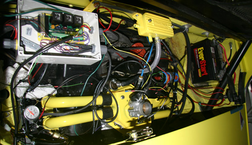
Posted by: yarin Apr 1 2006, 08:29 PM
i'm damn proud of that TPS adapter.
Attached image(s)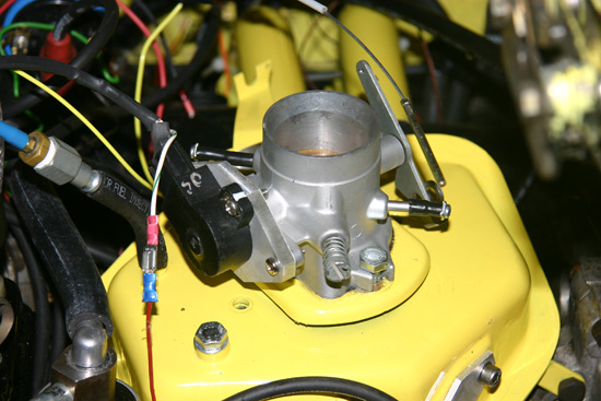
Posted by: yarin Apr 1 2006, 08:31 PM
This is wherei put my LC-1.
Also notice the fuel pressure gauge on the drivers side rail.
Attached image(s)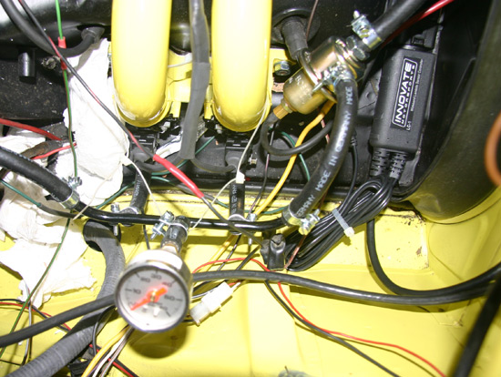
Posted by: yarin Apr 1 2006, 08:39 PM
I cleaned up the gas tank compartment. The support pads for the fuel tank rubbed the paint off the car so I dremeled off a few rust spots to bare metal and sprayed it with some 3M rubber protectant. At some point in the future I want to clean everything up and POR-15 some areas, so those black rectangles are temporary.
I installed new support pads as well, sticky back from walmart for $4.00 or so. Perfect for this application. It's as if they designed it for this purpose.
Can anyone tell me what front sway bar that is?
Posted by: yarin Apr 1 2006, 08:39 PM
oops
Attached image(s)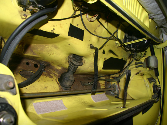
Posted by: TimT Apr 1 2006, 08:41 PM
Yarin, looks like a very nice EFI conversion.. cant help you out with mega squirt though since Ive never tuned one.
swaybar?
Posted by: TimT Apr 1 2006, 08:42 PM
take a picture of the swaybar ends, links and hardware, makes it easier to determine brand
Posted by: yarin Apr 1 2006, 08:42 PM
and another of the WBO2 sensor and wire routing.
Attached image(s)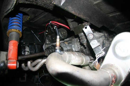
Posted by: yarin Apr 1 2006, 08:44 PM
| QUOTE (TimT @ Apr 1 2006, 06:42 PM) |
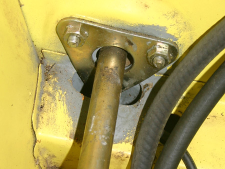
| take a picture of the swaybar ends, links and hardware, makes it easier to determine brand |
here ya go

Attached image(s)
Posted by: TimT Apr 1 2006, 08:45 PM
hmmmmm the end links etc that connect to the a-arm..
looks suspiciously like a weltmiester so far
Posted by: Jeff Nelson Apr 1 2006, 08:58 PM
yarin, Yes, nice TPS adapter! I just started making mine today so I can definitely relate. What TPS are you using? I hope it's cheaper than the Bosch part that I'm adapting.
I'm trying to figure out what everything is in your close up of the plenum. You've got a cover plate where the cold start injector would mount, a bolt where the air temperature sensor goes and what is the sensor attached with a bit of hose from a vacuum port? What air temp sensor are you using?
Your choice of yellow looks great and makes it really easy to see details in the pictures that you've posted. Nice work!
Posted by: yarin Apr 1 2006, 09:08 PM
| QUOTE (Jeff Nelson @ Apr 1 2006, 06:58 PM) |
| yarin, Yes, nice TPS adapter! I just started making mine today so I can definitely relate. What TPS are you using? I hope it's cheaper than the Bosch part that I'm adapting. I'm trying to figure out what everything is in your close up of the plenum. You've got a cover plate where the cold start injector would mount, a bolt where the air temperature sensor goes and what is the sensor attached with a bit of hose from a vacuum port? What air temp sensor are you using? Your choice of yellow looks great and makes it really easy to see details in the pictures that you've posted. Nice work! |
Thanks Jeff!
Good observations...
TPS - junkyard $10 off a mazda. Standard D-shaft.
Here are my plenum features:
Cold start injector blockoff
Air temp block off. I'm using the standard GM temp sensor in my custom PVC intake.
The vacuum port is just a complex bunch of adapters i found laying around the garage. It tees off to the MS map sensor and manifold referenced adjustable fuel pressure regulator.
stock Fast idle valve
Once its finished i'll clean it up a bit and start a site with all of the details. I hope to try to fire it up by Wednesday
Posted by: DNHunt Apr 2 2006, 07:14 AM
Yarin
Get a raw voltage off of the LC-1 and then compare it to the generated table that MS uses. Then trace that circuit at least to the DB37 coming out of the relay box. I can't remember for sure but, I'm not sure MS is getting the signal.
Also, my O2 sensor will not warmup and report correctly until on just battery voltage. The alternator has to be functioning. I'm not sure why that is except I suspect it draws a lot of current to heat the sensor. It is also possible that MS doesn't reference the voltage right until the alternator is up. If you take a look at the reported voltage to the MS ECU in Megatune it is probably under reported. Without the engine running it usually will report around 11.5 V at the ECU and I have 12.6 or so at the battery.
Dave
Posted by: Tom Perso Apr 2 2006, 08:23 AM
Could you throw a big battery charger/starter on to "pump" up the voltage a bit to see if that helps with the heating element?
I know MS will run on 9 volts, but all the ancillary stuff may take more.
Looks great so far. I like the box for the relay setup.
Tom
Posted by: yarin Apr 2 2006, 08:31 AM
I think the sensor is heating up, if it couldn't due to a lack of supplied current it would throw an error. I tried to power up the sensor off an AC/DC wall adapter and it gave a heater error. However now that its installed in the car it appears to be functioning properly. The problem is on the MS side, i'll trace it back through the relay box and check the tables.
If I hookup TPS Vref to the O2 input shouldn't that be a good test of the system in an attempt to display an AFR of 20 (5V input)??
Posted by: yarin Apr 2 2006, 09:50 AM
The only time the AFR changes is when the lc-1 is warming up, then the AFR drops to the bottom of the range. But as soon as it warms up it shoots to 25.5AFR.
I hooked the stim up to the MS again. I checked the potentiometer output and saw 0-1V on the O2 simulator. So I setup a custom wideband output in MS under Calibrate AFR for 0-1V 10-20AFR. That worked perfectly.
Then i decided to change my LC-1 to output 0-1V and 10-20AFR. With MS expecting 0-5V I saw ~14.5AFR with a known output of 1V from the sensor. So something is off in the tables.
Then I set MS to 0-1V in Calibrate AFR in MS. What do u know.... BAM 20.5AFR! Excellent.
For some reason it doesn't like the 5V signal, or the tables aren't correct. How do I check the tables? Where can i find the text table?
Posted by: DNHunt Apr 3 2006, 08:17 AM
Yarin
I'm not sure where to find that info. Maybe the Table editor. So, did I read it right? Do you have it straightened ou?
Dave
Posted by: crash914 Apr 3 2006, 08:47 AM
You might have to modify the .ini file...I think that you have to specify 0 to 5 volts in a couple of places... I remember a couple of wide band questions....
Posted by: yarin Apr 3 2006, 11:37 AM
| QUOTE (DNHunt @ Apr 3 2006, 06:17 AM) |
| Yarin I'm not sure where to find that info. Maybe the Table editor. So, did I read it right? Do you have it straightened ou? Dave |
Yes it appears to be functioning properly on the stim set to 0-1V. I'll learn more once the car is started, but I won't rely on the readings until I know its dead on. Worst thing I could do is tune to an AFR that is WAY off.
I'll dig into the .ini files and see what i find.
Posted by: jkeyzer Apr 3 2006, 02:13 PM
I think fiid and I ran into this scenario. Megatune doesn't properly display AFR until the car is running.
Posted by: crash914 Apr 3 2006, 02:31 PM
it will also show way lean with the motor not running..... 
Posted by: yarin Apr 3 2006, 02:42 PM
well then... that may be my problem. i hope to find out in a few days
Posted by: DNHunt Apr 3 2006, 02:58 PM
Yep' turning the ignition to on without starting the engine the O2 will read way lean in Megatune
Dave
Powered by Invision Power Board (http://www.invisionboard.com)
© Invision Power Services (http://www.invisionpower.com)