Printable Version of Topic
Click here to view this topic in its original format
914World.com _ 914World Garage _ Volocity stack design considerations??
Posted by: Mueller Apr 4 2006, 03:19 PM
Slightly warmed up /4 motor applications...I'm thinking just about any design better than none at all....I'd like to metal spin these myself, however if I can get a good price on 8 from a fellow non-club member, I'll go that route 
Attached image(s)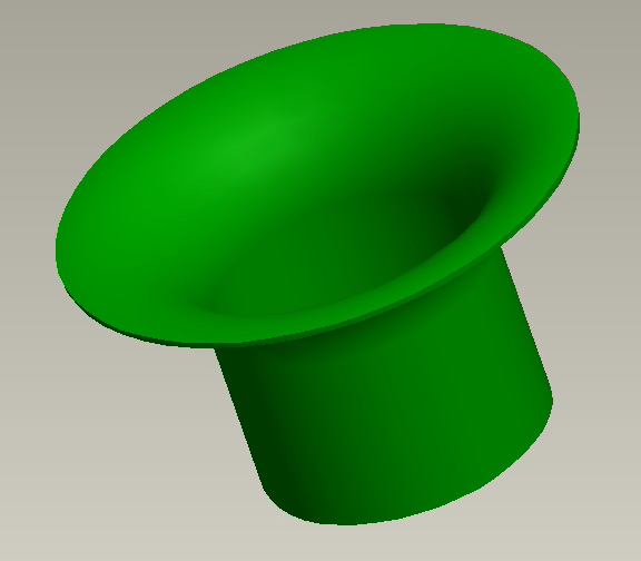
Posted by: bd1308 Apr 4 2006, 03:42 PM
carbs have had velocity stacks for years....
Posted by: spunone Apr 4 2006, 03:52 PM
Just send me the measurements and if we ever meet up you can buy me a few  no need to try it yourself unless your really bored
Posted by: spunone Apr 4 2006, 04:04 PM
You can roll outer edge back onto itself I have made a few like that or just the straight edge like your pic how close togeather are they you may need to notch edge and weld just some ideers
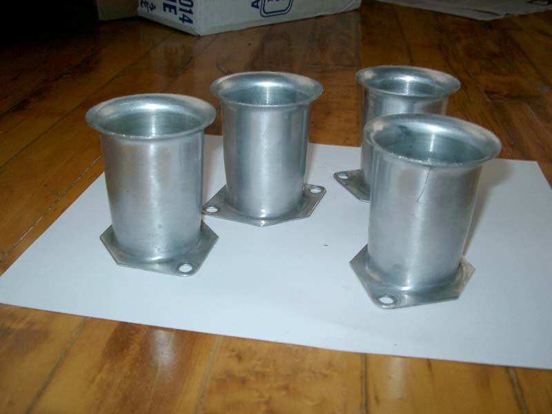
Posted by: SirAndy Apr 4 2006, 04:14 PM
| QUOTE (Mueller @ Apr 4 2006, 01:19 PM) |
| I'd like to metal spin these myself |
make 'em longer. much, much, much longer ...
torque is what you want, right?
 Andy
AndyPS: if you get my axle done, i'll give you these for free!

2 3/4" high, set of 4
Attached image(s)
Posted by: jsteele22 Apr 4 2006, 04:27 PM
Hey Mike,
Don't know if you've run across this, but this page at http://www.sdsefi.com/air12.html describes making velocity stacks by machining a form out of steel, then pressing the stacks over the form with a hydraulic press. Might be a nice way to go if you're thinking of producing multiple units...
Are you planning on having the stacks out in the open or inside a plenum ?
Posted by: ClayPerrine Apr 4 2006, 04:38 PM
http://www.velocity-of-sound.com/commerce/search/index.php3?merchant_id=2107&keywords=&search_type=ANY&custom_store_category=8&by_category=+++GO%21++
Posted by: ClayPerrine Apr 4 2006, 04:40 PM
I still want to know why you are reinventing the wheel???
http://www.twminduction.com/ThrottleBody/ThrottleBody-FR.html
Posted by: ClayPerrine Apr 4 2006, 04:41 PM
If you are really pimpin'. http://www.twminduction.com/AirHorn/AirHorn-FR.html
Posted by: Mueller Apr 4 2006, 05:14 PM
| QUOTE (bd1308 @ Apr 4 2006, 02:42 PM) |
| carbs have had velocity stacks for years.... |
uh, thanks for the history lesson..I think


| QUOTE |
| I still want to know why you are reinventing the wheel??? |
why did you build a /6 conversion when you could have bought one?? so far, t/b's have cost:
- t/b's with TPS, injectors and fuel rail = $140
- manifolds = $40 for the pair
- rubber hose = $2 each
- clamp = $6
- machining time = 1 hour including setup
*he paid I think $200 or so for his motorcycle t/b's which I am modifing as well...
Andy,
One end of the axle is done, just need to do the other one, tonight I'll try to get it done. Diameter is critical.....
Paul,
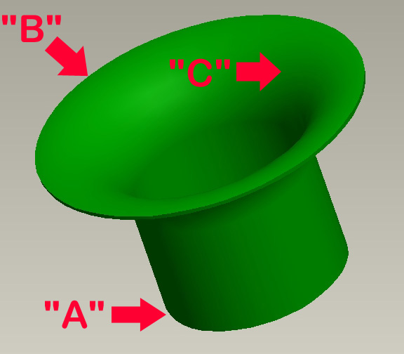
I can send you a real drawing if I can get my computer from crashing due to new video card

So far...
"A"...minimum ID to be 47mm, max OD 55mm (I doubt you'd use .156 or thicker material
)"B" 90mm before overlapping
"C" whatever R is easy for you, nice big one will work for me
Overall height, I'm thinking somewhere between 2" and 3" due to aircleaners, unless I can find a nice tall aircleaner (something smaller than the 9" units I've seen at the bug places)
Attached image(s)
Posted by: Thorshammer Apr 4 2006, 09:05 PM
The outer lip needs to be rounded. The edge is very important to good airflow. I have some stacks that are length adjustable for webers that I will be making in the next couple months. Not sure if you can wait.
Erik Madsen
Posted by: retrotech Apr 4 2006, 09:48 PM
I tested air flow with vacume cleaner suction & smoke, on standard sharp edge velocity stacks, versus rounded/rolled edge. The air flowed significantly better with the rounded edge. It was really difficult for the air/smoke to travel freely around that hard edge.
Posted by: Twystd1 Apr 5 2006, 12:43 AM
YUP... What everybody else said about the rounded edge.
He Paul.. I know you have made these before. Can ya make a clone of the TWM style rounded edge stacks??
Word is from the head porters I know, that is the correct shape (or close to it)
One guy flows heads with the complete intake system attatched.
He say's the rounded edge doesn't really give them much more CFM.
But it does give them more uniformity of flow. Especially on carbs. Cause carbs need the velocity and proper flow charachteristics to get the fuel sucked out of the transition ports and the center anular ring effectively. They say it makes a great differance on transition from idle to mid or full throttle. (on carbs)
Other than that.. I don't know any real data...
By da way... take a look at those factory RACE ENGINES that were at the Pelican auction a couple of weeks back... (pics at PP board)
ALL velocity stacks were rounded over.
Paul.. You and I looked at em at the swap meet...
Clayton
Posted by: Porcharu Apr 5 2006, 02:09 AM
Get that mill going Mike. Make an insert and press or pound it into some dead soft aluminum, my college roommate did this and made some very nice parts. You could also go low tech and just mill some MDF radiused inlets - it works just fine.
Posted by: jsteele22 Apr 5 2006, 11:28 AM
I don't know anything about the design of velocity stacks, but that ain't gonna stop me from spouting off....
I think Twystd1 is right : the place where stack design matters most is for carbs, 'cause the detailed behavior of the air flow determines how much fuel you get from the venturi, and also how well the fuel/air get mixed. Since F/I handles these two issues very reliably, you mainly want to keep the flow from going turbulent : laminar flow (where air flows smoothly in layers parallel to the tube walls) will get you more air, so more power. My guess is that using *any* sane velocity stack profile will get you like 80% of the way there, and the only thing to get you to the ideal is gonna be trial and error, and/or massive amounts of computer modelling.
If there is no velocity stack, only an abrupt open tube end, then when a "vacuum pulse" reaches the top end of the pipe, it's gonna want to draw air in from every direction. Air directly above the pipe will flow right in, but air that is directly to the side of the pipe is gonna have to make an infinitely sharp 90 degree turn if it's gonna follow the tube wall. Since it can't, it's gonna understeer and separate from the wall, giving rise to turbulence.
Adding a bell shape does (at least) two things. It gives the air thats out to the sides of the stack a nice gentle curve to follow as it goes from flowing sideways to flowing downward. This in itself reduces the likelihood of turbulence. But the area of the tube opening is also made quite a bit larger. Twice the area means that the air is traveling half as fast as it enters. Then add to this the fact that air travelling along the tube walls is gonna travel much more slowly, due to friction, than the air flowing down the center. So the outer part of the flare is like a landing pad/slow lane for getting the most problematic air flowing in a nice oderly way side by side with the bulk of the air which is coming from the more vertical directions. As for the rounded lip issue, yeah its got to help some, in theory, but I think that by the time you get out to the lip the air velocity along the bell surface is pretty small, so it's really gonna be a hair-splitting kind of issue. If you were going for massive HP (i.e. massive air flow) then it might be worth doing. But for this project, I can't see it showing up on the radar.
All of the above (besides being pure speculation on my part) only describes the steady-state behavior. In the intake, you're really looking more at pulses of negative/positive pressure superimposed on top of this. I've heard, and it makes some sense, that another thing velocity stacks accomplish is to broaden the torque peak.
Posted by: maf914 Apr 5 2006, 01:31 PM
Lot's of good ideas, but how come no one has mentioned carbon fiber? That would make it a lot faster! 
Actually, when you wander around the paddock at sports car and formula car events, most of the newer racing engines use carbon fiber horns, and the outer lips are quite rounded. These are all injected engines but obviously the consensus is that rounded is better. All of this is typically hidden in a sealed airbox feed through one or two air restrictors.
Posted by: Mueller Apr 5 2006, 01:38 PM
| QUOTE (maf914 @ Apr 5 2006, 12:31 PM) |
| Lot's of good ideas, but how come no one has mentioned carbon fiber? That would make it a lot faster! Actually, when you wander around the paddock at sports car and formula car events, most of the newer racing engines use carbon fiber horns, and the outer lips are quite rounded. These are all injected engines but obviously the consensus is that rounded is better. All of this is typically hidden in a sealed airbox feed through one or two air restrictors. |
they are pretty aren't they ???


Posted by: Aaron Cox Apr 5 2006, 01:43 PM
yummy jenevey's 
Posted by: Aaron Cox Apr 5 2006, 01:44 PM
OMG! they even make "injected air horns"!!! like that would be uber cool!
Posted by: Mueller Apr 5 2006, 01:50 PM
aaron,
here is video showing how many of the spun volocity stacks are made...
http://www.franjometal.com/metal-spinning/spinning-videos.html
Posted by: spunone Apr 5 2006, 01:50 PM
Ok one more for ya fellas .On a few nitro drag bikes they use a rounded edge stack with a smaller stack say half the size inside of it welded in place with 3 tabs perpendicular to each other.they say this increases air flow about 45% and need to lean it out a shit load from conventional single stack.I myself don't know nuttin just somethings I hear from time to time .Also TRD racing uses Alum round edge stacks about 8 inches long to start put motor on Dyno then they start cutting them down to who knows what size for peak HP on the special race motors Again just something I hear .Glad I gots big ears 
Posted by: jsteele22 Apr 5 2006, 02:43 PM
I don't know why two stacks would give more airflow, but I guess there's a tradeoff : more surface area causes more drag (bad) but the additional stack does a better job of guiding the air into the tube without tumbling (good). Kind of like going from 16 lanes down to 4 after a toll booth : doing the merges in two steps seems to work a little better. Again, trial and error is probably the primary means to pick the best setup, and if that doesn't work, just go w/ carbon fiber.
About the length, the longer the tube the more air is moving in one direction at the same velocity. Like the marching band in Animal House, once the head of the column reaches a dead end (the piston) the rear of the column keeps pushing forward due to it's momentum. But long tubes also cause more friction, so at high RPMs it's mostly just a hindrance.
Since intakes don't run that hot, they can be made out of nice light, workable materials - the "test and chop" method sounds like a great way to go to find the perfect length. Exhaust systems, OTOH, have to be heavy, and therefore are a PITA when it comes to trial and error. It would be so nice to make up a test set of headers and exhaust out of, say, PVC pipe and run for ??? seconds before they melted through....
Posted by: john rogers Apr 5 2006, 02:49 PM
Something to think about, are you going to run air cleaner(s) and if so which ones? Or are you going for the tall Hilborn injector Can-Am look? When my race engine was dyno'd taller stacks were used and I had to go to taller filter elements which just about touch the engine cover on the 914 and that is with the enging sitting an inch lower than stock. The taller the stacks, the higher in RPM range all things being equal but for a given cam, head combination there is a stack height for the best power production and mine happened at 7000 RPM with the parts we had.
Posted by: Aaron Cox Apr 5 2006, 03:25 PM
what if you had 4 different size stacks????

torque, top end, and mid range LOL
Posted by: jd74914 Apr 5 2006, 03:27 PM
| QUOTE (Aaron Cox @ Apr 5 2006, 04:25 PM) |
| what if you had 4 different size stacks???? torque, top end, and mid range LOL |
Or adjustable ones that taper down so they can be collapsed and expanded easily depending on the desired change.

Posted by: jsteele22 Apr 5 2006, 03:28 PM
| QUOTE (Aaron Cox @ Apr 5 2006, 02:25 PM) |
| what if you had 4 different size stacks???? torque, top end, and mid range LOL |
Well, you'd want some way to select the right one at the right moment. Don't want the switches to look ugly, though. Maybe use ivory, with some shorter ebony ones in between.
Posted by: Aaron Cox Apr 5 2006, 03:29 PM
| QUOTE (jd74914 @ Apr 5 2006, 02:27 PM) | ||
Or adjustable ones that taper down so they can be collapsed and expanded easily depending on the desired change. |
wasnt that called active induction? ala growing stacks on a mazda no? got banned in some racing thing for it...
Posted by: jsteele22 Apr 5 2006, 03:42 PM
| QUOTE (Aaron Cox @ Apr 5 2006, 02:29 PM) | ||||
wasnt that called active induction? ala growing stacks on a mazda no? got banned in some racing thing for it... |
Actually, the Subaru SVX had some kind of system for altering the intake path. I think it was a flapper similar to a throttle body that was actuated by a vacuum servo to switch between low- and high-rpm modes. THat would be a fun thing to stitch into MegaSquirt one of these days...
Posted by: bd1308 Apr 5 2006, 04:02 PM
guys, we need to think outside of the box.
I am going to go ask teh UFO guys to see if we could get some primordial goo and train it to morph into a tall, medium and short sized velocity stacks for us.
Hey they'd do it for years, just to see Miles--their father.
b
Posted by: TimT Apr 5 2006, 04:15 PM
| QUOTE |
| wasnt that called active induction? |
AKA Varioram used on the latest /6 ers..varies the intake length
Posted by: Aaron Cox Apr 5 2006, 04:18 PM
| QUOTE (TimT @ Apr 5 2006, 03:15 PM) | ||
AKA Varioram used on the latest /6 ers..varies the intake length |
what activates it? or... what mechanicly drives it?
Posted by: TimT Apr 5 2006, 04:33 PM
Let Steve Timmins explain
http://instant-g.com/Products/36Conversion/VRAM.html
He is a physics professor at Univ of Del... teaches vehicle dynamics and stuff
Posted by: Rick_Eberle Apr 5 2006, 06:11 PM
Here's what Suzuki use on their current GSX-R's. The velocity stack is rubber, with slots in the side, supposedly to reduce pulses in the intake. The stack also seals the tb to the airbox.
Attached image(s)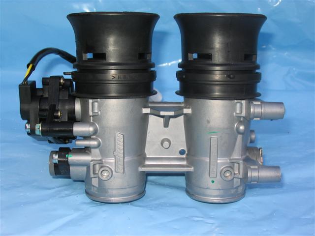
Posted by: Rick_Eberle Apr 5 2006, 06:12 PM
Showing the slots...
Attached image(s)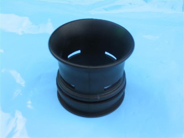
Posted by: maf914 Apr 6 2006, 09:15 AM
| QUOTE (Rick_Eberle @ Apr 5 2006, 04:11 PM) |
| Here's what Suzuki use on their current GSX-R's. The velocity stack is rubber, with slots in the side, supposedly to reduce pulses in the intake. The stack also seals the tb to the airbox. |
Those slots are different. I've never seen that before. Cool!
I'd like to read an explanation of the idea behind that design.
Posted by: maf914 Apr 6 2006, 09:21 AM
| QUOTE (Aaron Cox @ Apr 5 2006, 01:25 PM) |
| what if you had 4 different size stacks???? torque, top end, and mid range LOL |
In the old Can-Am days almost everyone ran with tall intake stacks. Some engines ran with staggered height stacks. I don't know if this was to deliberately tune various cylinders for different power characteristics or to prevent equal height stacks from stealing airflow from adjacent stacks. Regardless, they looked cool!
Posted by: Rick_Eberle Apr 6 2006, 06:42 PM
| QUOTE (maf914 @ Apr 7 2006, 02:15 AM) |
| Those slots are different. I've never seen that before. Cool! I'd like to read an explanation of the idea behind that design. |
Here you go... not much detail, unfotunately.
http://www.mcnews.com.au/NewBikeCatalogue/2001/Suzuki/suzukigsxr1000page2.htm
These tb's also have a secondary throttle plate worked by a stepper motor driven by the ecu. It lets them control the velocty into the ports at low rpm, and get back some mid-range.

That would be cool to run with MS.
Posted by: J P Stein Apr 6 2006, 06:51 PM
| QUOTE (maf914 @ Apr 6 2006, 07:21 AM) | ||
In the old Can-Am days almost everyone ran with tall intake stacks. Some engines ran with staggered height stacks. I don't know if this was to deliberately tune various cylinders for different power characteristics or to prevent equal height stacks from stealing airflow from adjacent stacks. Regardless, they looked cool! |
From what i've read, the different length stacks were to
tune the engine to run as 2 4cyl engines. Apparently, there was a dip in the torque curve that this tuned out.....tho it's hard to imagine an 8+ liter BBC with too little torque anywhere
"Some" dyno time to figure that one out, eh?
Posted by: Porcharu Apr 6 2006, 10:42 PM
| QUOTE (maf914 @ Apr 6 2006, 07:21 AM) |
| In the old Can-Am days almost everyone ran with tall intake stacks. Some engines ran with staggered height stacks. I don't know if this was to deliberately tune various cylinders for different power characteristics or to prevent equal height stacks from stealing airflow from adjacent stacks. Regardless, they looked cool! |
I think the staggered stacks were to equalize the different port lengths on the big block chevy heads. Those heads have two differently designed intake ports per head.
Posted by: fin Apr 7 2006, 08:16 AM
I believe the formula for a proper roll on the mouth of the stack is one fourth of the diameter of the tube.
So a 50mm TB would need a roll of 12.5mm.
The different lengths of the velocity stacks was for tuning pairs of cylinders for different torque/HP sweet spots, giving the motor a wider torque band. Once transmissions increased to five or more gears, the designers went back to a narrower and higher torque bands.
In the Ferrari museum, I saw velocity stacks with the invector centered in the top and pointing straight down into the intake. Looked very cool. Especially on a single cylinder test motor.
CNC lathe would do a better job than a mill, but if that's what you have, make it work!
Fin
Posted by: dstar Apr 7 2006, 08:42 AM
| QUOTE (Rick_Eberle @ Apr 5 2006, 04:12 PM) |
| Showing the slots... |
I've been doing that to my Dell/IDF stacks for years.
Four cuts with a band saw and you're done.
It gives the reversion pulse an out, to keep from disturbing the
air flow that is already headed in the direction of the intake.
How does this idea work, you ask?
Physics folks, simple physics.
Don
Posted by: Mueller Apr 7 2006, 04:31 PM
| QUOTE |
| Slots in the base of the throttle-body air funnels (also known as velocity stacks) inside the airbox reduce intake pulses to smooth mid-range power delivery |
taken from press release for 2003 GSX-R 1000
hmmm.....good excuse to get the "A" axis (4th) running on my mill

Posted by: spunone Apr 7 2006, 04:54 PM
Sample stack headed out today UPS have fun
Posted by: Mueller Apr 7 2006, 05:27 PM
| QUOTE (spunone @ Apr 7 2006, 03:54 PM) |
| Sample stack headed out today UPS have fun |

thanks...I'll post pics as soon as I get it....
Posted by: Thorshammer Apr 7 2006, 11:06 PM
Since I worked for Suzuki for 5 years, I thought I might comment on this particular situation.
Yes, the slot in the rubber velocity stack was to reduce the intake reversion on this model, The 2003 had different cams that caused some minor fuel distribution issues we worked out by doing this simple mod. It does not work in all applications. The intake port velocity on this engine is completely different than that of the 914 4/6engine. Also a GSXR1000 will regularly spin to 12,600 rpm. None of us ever will, or at least we will not have any straight valves after that.
This mod would be an R&D affair. For GSXR 1000 race engines I build, we remove these stacks and install a stack that is a touch shorter, with a 12mm rounded edge which increases flow and changes the torque peak. The stack is also void of all slots unlike the standard piece.
As far as 4D to determine the correct radius for the velocity stack bellmouth, this would be a good starting point, I checked some of the ones I have and they range from 3.5D to 5D. Interesting. I wish I could give you a reason why I arrrived at the sizing I did, but I don't.
This is one area we have not discussed, and I have a trial set for my next dyno run. I really think aircleaners are very important, But I have glued a upside down top shaped piece of plastic to the under side of the air box pointed towards the carb velocity stack. I am hoping to guide some more air into the carb without restricting it. Stole the idea from Buell motorcycles. We'll See!
Erik Madsen
Posted by: Rick_Eberle Apr 8 2006, 11:20 PM
| QUOTE (Thorshammer @ Apr 8 2006, 04:06 PM) |
| The intake port velocity on this engine is completely different than that of the 914 4/6engine. Also a GSXR1000 will regularly spin to 12,600 rpm. None of us ever will, or at least we will not have any straight valves after that. |
Wouldn't a 2.0 turning at 6000RPM be moving a similar amount of air as a 1.0 at 12000RPM?
Posted by: Thorshammer Apr 9 2006, 08:56 AM
Actually, No.
Volumetric efficiency of the GSXR vs the 914 engine is significantly different. The GSXR will make 172 hp at the countershaft whereas the 914 will make ? for a 2.0 to make 172, it would be a very well tuned 2.0 liter. But to put things in a cc/hp perspective, a 2.0 liter 914 engine would make 344 hp to be an equal amount of HP per cylinder. However the frictional losses and thermal differences between these engines change everything. CC/airflow is a very difficult comparison. This is why they will take completely different set ups. Double the CC's would need double the carb size as well, if things were proportional, does anyone have any 84mm throttle bodies.
Erik
Posted by: Rick_Eberle Apr 9 2006, 11:46 PM
| QUOTE (Thorshammer @ Apr 10 2006, 01:56 AM) |
| does anyone have any 84mm throttle bodies. |
If they did, I bet the type 1 guys would buy 'em!
Posted by: Rick_Eberle Apr 10 2006, 04:02 AM
| QUOTE (Thorshammer @ Apr 10 2006, 01:56 AM) |
| Double the CC's would need double the carb size as well, if things were proportional, does anyone have any 84mm throttle bodies. |
Hang on a minute, that would be true if the RPMs were the same, but at half RPMs, the size would be the same (assuming of course that the state of tune was similar, which maybe Jake could do, but not me). Also, an 84mm tb is four times the size of a 42mm. Double the size would be around 59.5mm. It's the intake area that matters, isn't it?
Powered by Invision Power Board (http://www.invisionboard.com)
© Invision Power Services (http://www.invisionpower.com)