Printable Version of Topic
Click here to view this topic in its original format
914World.com _ 914World Garage _ Gauge Cluster Wiring
Posted by: StratPlayer Oct 10 2003, 11:16 AM
I'm about to tackle the gauge cluster wiring, it seems that there are some wires that are not in the correct place etc.. I was wondering if there were any diagrams of the gauge cluster wiring or any pictures of a later model teener with the correct wiring for the gauge cluster. I have a combo gauge that I'm going to install and want to go thru the wiring an make sure that it is all correct.
Attached image(s)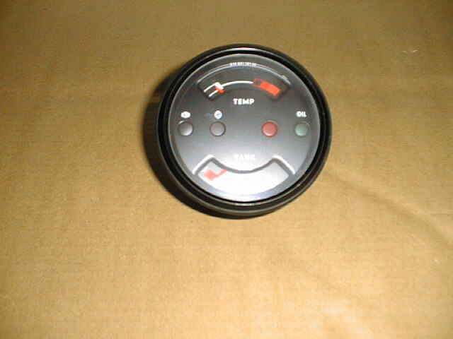
Posted by: StratPlayer Oct 10 2003, 11:17 AM
I have an extra one of these gauges if anyone is in need.
Attached image(s)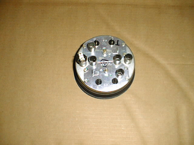
Posted by: Brad Roberts Oct 10 2003, 12:08 PM
We need to scan the color'd wires diagram.
You might be better off asking what wire color does what.
Like list off everything you see on the BBS and let us tell you where each wire should go.
I can look at it and tell you.. but I cant tell you from memory.
B
Posted by: Kerrys914 Oct 10 2003, 12:26 PM
If someone can fax me a hand sketch of their corectly wired gauge cluster I will pretty it up of posting on the club site. 
Or
Three close up photo's e-mailed to me kerrys914@comcast.net
Cheers 
Kerry H
804-217-8520
Posted by: StratPlayer Oct 10 2003, 01:09 PM
Trying to post a sketch I made when I removed the gauges, but keep getting timed out on the upload of the sketch.
Posted by: StratPlayer Oct 10 2003, 01:20 PM
xoxoxxo
Attached image(s)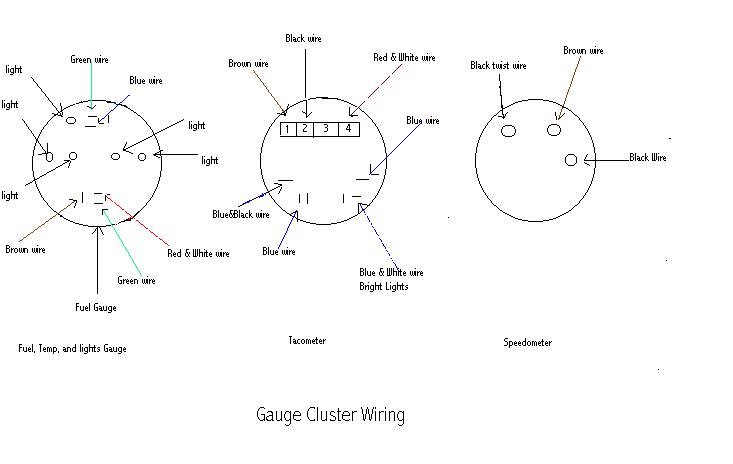
Posted by: StratPlayer Oct 15 2003, 02:16 PM
 Maybe one of you can fill the rest of these out
Gauge Cluster Wiring (Combo Gauge)
Brown Wire = Ground
Black w/Blue Stripe = Instrument Illumination
Red w/White Stripe = Swithched Power On
Green w/Black Stripe = ??
Blue = ?
Green = ??
Posted by: Dave_Darling Oct 15 2003, 04:50 PM
Green/black == oil temperature gauge signal
Blue == alternator light
Green == fuel gauge signal
Green/red == oil pressure light
Black == low fuel light
There may be others I'm forgetting....
--DD
Posted by: StratPlayer Oct 15 2003, 05:10 PM
 Thank You Dave, deeply appreciated,
Powered by Invision Power Board (http://www.invisionboard.com)
© Invision Power Services (http://www.invisionpower.com)