Printable Version of Topic
Click here to view this topic in its original format
914World.com _ 914World Garage _ Build your own Combo (904) Gauge
Posted by: 914forme Apr 23 2006, 06:48 PM
Well here it goes the step by step instructions on how to build one of the kits. Since I helped do the original production run, back in the day, its been about 11 years ago since we did these. But there is interest in it so I will show you how.
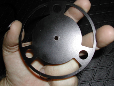
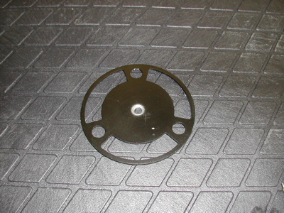
Step one, the original kit. It included a gauge face, a backing plate and a ground lug. Also included instructions on how to do this, and some of the items where real PITAs to do. I will included some changes I do, and items that might make the installation a little easier.
Attached image(s)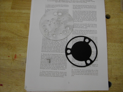
Posted by: 914forme Apr 23 2006, 06:51 PM
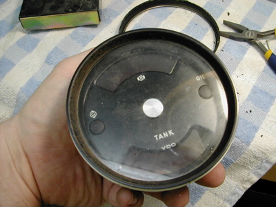
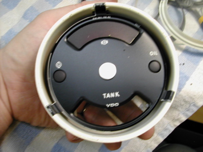
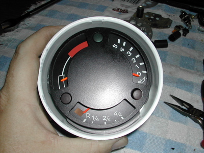
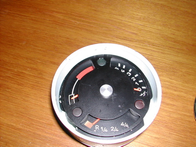
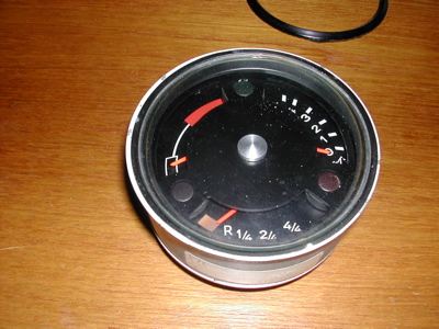
Next you have to gather two instruments, chance are one you already have. It is what everybody calls a 914 combo gauge. Most have a huge brake warning light, rarer are the ones that include an oil temperature gauge. So you can take one out of your car, or source a different one.
Attached image(s)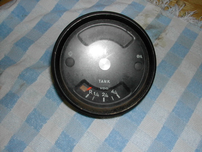
Posted by: 914forme Apr 23 2006, 07:00 PM
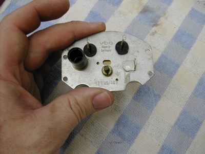
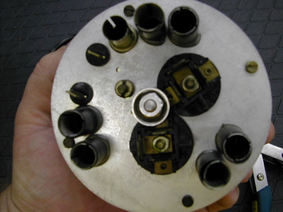
The back of the gauge will look like this notice the spade connectors. This is the early style - I will show you how to setup for the latter style gauge also. It is much easier to mount.
Attached image(s)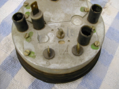
Posted by: 914forme Apr 23 2006, 07:01 PM
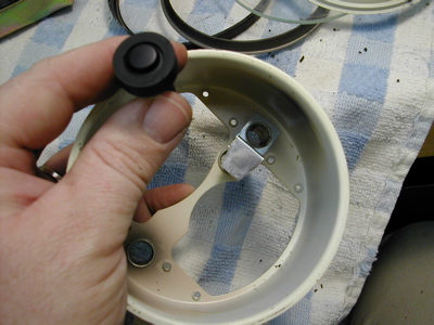
A late model gauge will have a connector like this.
Attached image(s)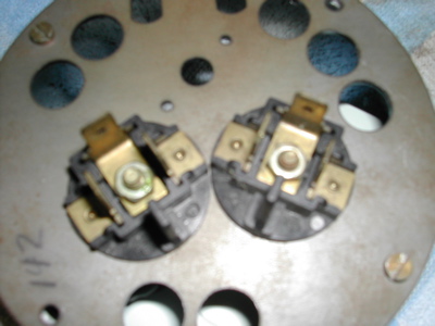
Posted by: 914forme Apr 23 2006, 07:02 PM
The other is a 911 oil temperature gauge and pressure gauge, you need the latter style, it looks something like this. Not this is an early model with spade connectors. I have one already apart, that has the correct late style connectors. Jot down the year of the car that the gauge came out of it you know it. You will need it latter to pick the correct senders. Chart will fill in the details.
This is an early gauge - its the only one I had together.
Attached image(s)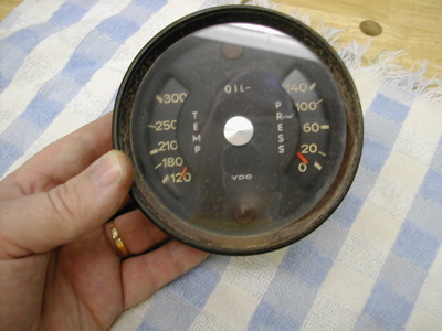
Posted by: 914forme Apr 23 2006, 07:04 PM
The connectors are the same as posted two above. You really need these, you could modify the backer to hold the early style gauges, but you ill be hating life, they are a real PITA.
Posted by: 914forme Apr 23 2006, 07:07 PM
Tools of the trade:
Screw drivers flate blade
7mm nut driver
Pliers
Nibblers
Snips
A large Drill bit, I use a 3/4 inch, but a 1/2 will do.
A soldering Iron if you are using the early style fuel gauge.
Plenty of time and patience
Attached image(s)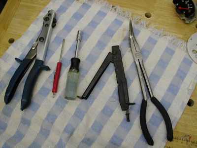
Posted by: 914forme Apr 23 2006, 07:10 PM
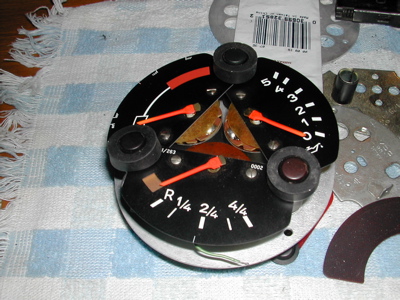
First step is to remove all the gauge mechanisms out of the back side of the gauges bodies.
4 screws hold these in place.
Place the gauge face down on a cloth and take them out. Keep all your parts until you finish the build.
Attached image(s)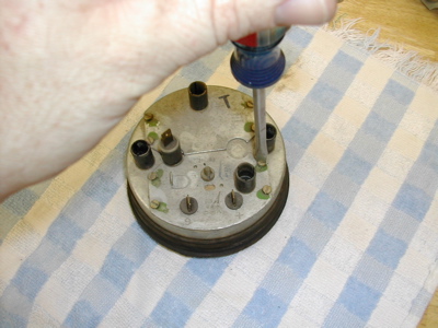
Posted by: 914forme Apr 23 2006, 07:15 PM
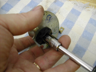
The fuel gauge will come out, but you can't pull it straight up. You must tip it and raise the right side up first if your looking at it closest to you. Just be gentle it does come out of there. 
Attached image(s)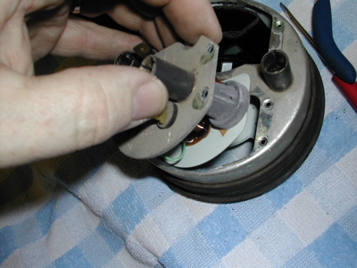
Posted by: 914forme Apr 23 2006, 07:17 PM
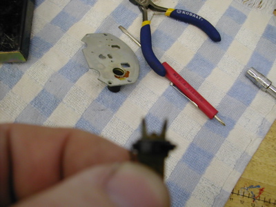
Here it is out of the gauge front view, and rear view also.
Attached image(s)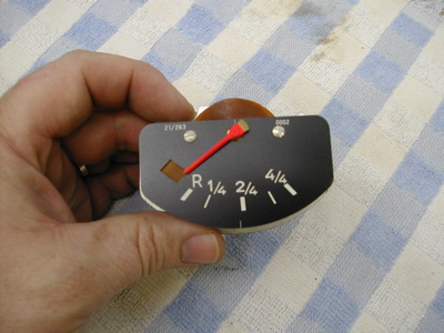
Posted by: 914forme Apr 23 2006, 07:21 PM
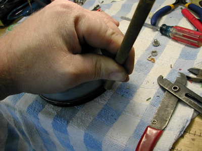
I like to take them apart along the way. It is just how I do it, not sure why its just how I have done them for years. So first you need to heat up the soldering iron, and remove the solder from the two spade connectors. I heat the solder up, and strike the gauge back against the bench with a tap, the solder will fall off. Watch out you can burn yourself good doing this. You could also use solder wick if you wanted.
Attached image(s)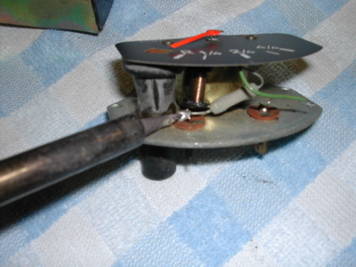
Posted by: 914forme Apr 23 2006, 07:24 PM
Next you remove the gauge mechanism from the mounting plate, on the early 914 fuel gauge it is one simple nut. It requires a special tool, if you want to keep it concourse, I use this! A pair of BMFP
Attached image(s)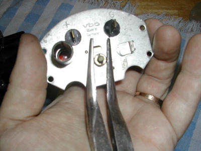
Posted by: 914forme Apr 23 2006, 07:30 PM
Next is wheere the fun really begins, removing the spade connectors from the mounting plate.
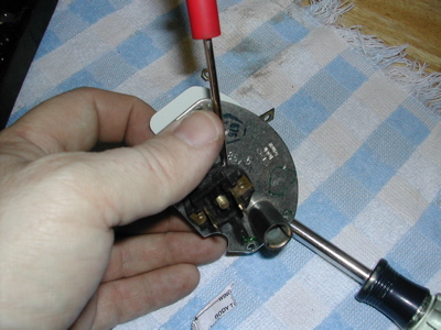
First you must bend up the little tabes that hold the connector onto the mounting plate. There are two pe connector, be really careful or else you break the conector. And life becomes a little but harder.
So first I take a really small screwdriver and wedge it between the fiber insulator and the gauge mount plate lik this. Slide it in and gentaly pry up. Next I do the same ontop of the fiber insulator, and last I grab it with a small set of kneedle knows pliers and make it straight.
Attached image(s)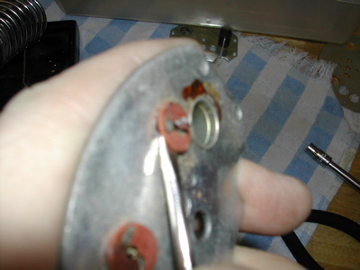
Posted by: 914forme Apr 23 2006, 07:33 PM
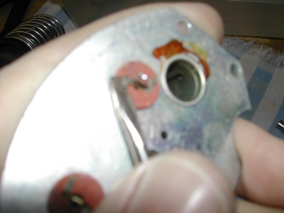
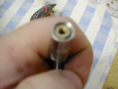
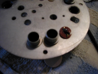
Note to self pull camera back, dang those where blurry.
Okay I take my small pliers and screw drivers and gently pull the fiber ring up off the connectors. the connector will fall out after this is done, so make sure you track where it goes.
Attached image(s)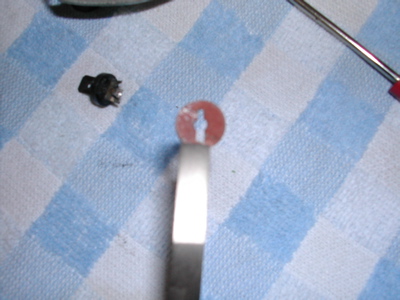
Posted by: 914forme Apr 23 2006, 07:36 PM
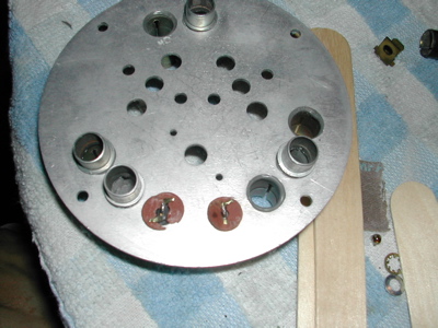
Left is a good connector, right is one I screwed up.  so be careful, take your time, or else you will be looking at other ways of fixing this problem.
Attached image(s)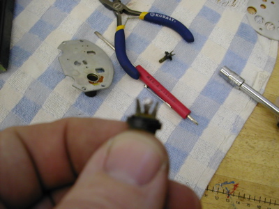
Posted by: 914forme Apr 23 2006, 07:39 PM
Next up the 911 oil temp and pressure gauge mechanism disassembly, the are both the same so just repeat and rinse these twice. Well three times if you use a late style fuel gauge. You will now see why I recommend using the late style fuel gauge. This is so much easier, and you don't risk getting burnt. Tip here: stuff a little paper into the tip of your 7-mm socket or nut driver, it will make it easier to reassemble the gauge pieces latter. The nut won't burry itself in your socket and never start back on the shaft. Trust me there is no room for your fingers in there. Second is who the nut will look since you modded your nut driver.
Attached image(s)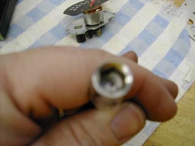
Posted by: 914forme Apr 23 2006, 07:47 PM
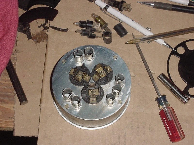
Pretty simple here you take your 7-mm nut driver. And back out the nut in the center of the three spade connectors. The center ground lug will come off with the nut. If you can not remove the connector from the mount, you can take that small screw driver and pry up gently it will pop off, and everything will fall apart.
Attached image(s)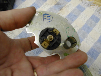
Posted by: 914forme Apr 23 2006, 07:50 PM
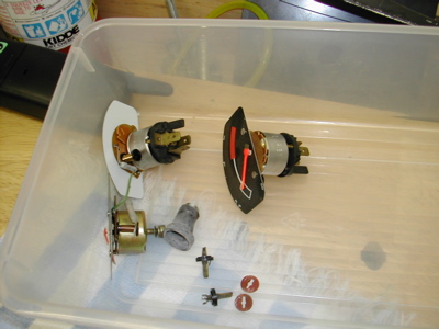
Now the best part, put all these dissasembled pieces into a storage container re-assembled. Note the order of how the early fuel gauge goes togtheer.
Attached image(s)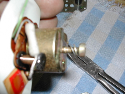
Posted by: 914forme Apr 23 2006, 07:58 PM
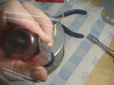
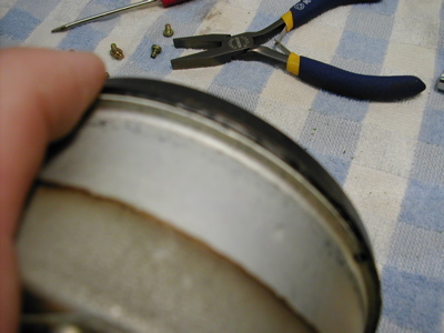
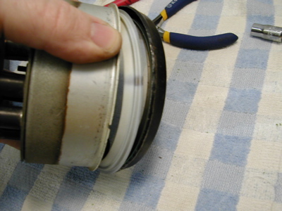
Now onto the real fun, takeing the bevel apart. The pros just cut them off you are about to see why. First remove the rubber surround. Next you need to have a gental touch and don't worry about the paint that flakes off, thats fixable. You strat by gentally twisiting your screw driver, I made a special tool for this I have since lost. 
Move the bevel metal out a little at a time. A trick I use is I only go around the bevel , 2/3rs of the way. With some minor struggle it will come off. And then you have less to repair latter. Take your time here. It is worth it in the long run, trust me. 
Attached image(s)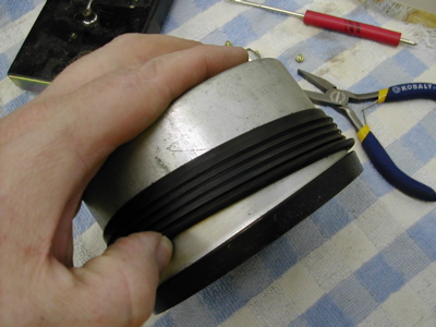
Posted by: 914forme Apr 23 2006, 08:01 PM
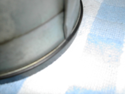
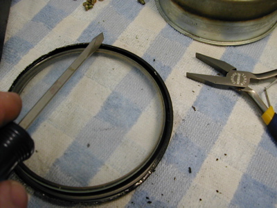
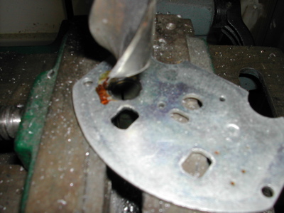
Boy I wish I had photshop right now. The screw driver is pointing to where I started and stopped my bevel decrimping. About 2/3rds of the way around.
Attached image(s)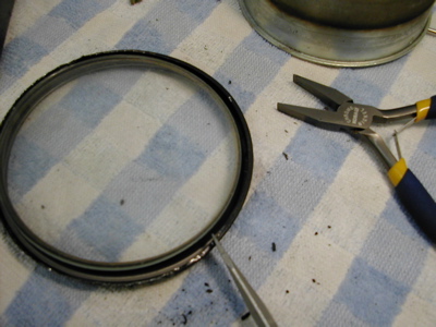
Posted by: 914forme Apr 23 2006, 08:05 PM
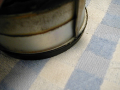
This is the order that the bevel comes apart.
1. Trim ring outer
2. Trim ring inner, yep there are two of them.
3. Glass or plastic, if you have plastic and a glass unit use the glass.
Attached image(s)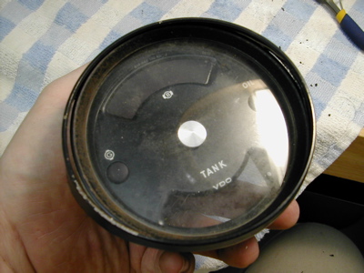
Posted by: 914forme Apr 23 2006, 08:07 PM
Next up after the glass is removed, you have an inner trim ring.
After that the guage face. 
Attached image(s)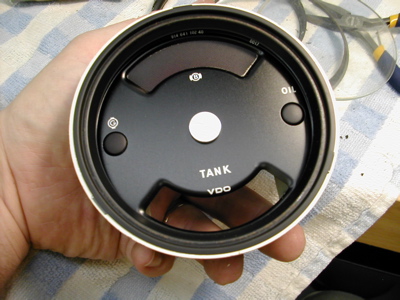
Posted by: 914forme Apr 23 2006, 08:09 PM
After that we have the inner guts of the gauge. Some times the light lenses stick to the gauge face other times they stay in the gauge its self.
Attached image(s)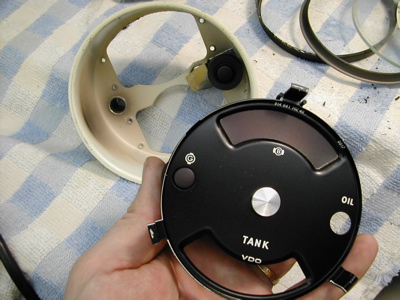
Posted by: 914forme Apr 23 2006, 08:10 PM
They are easily removed with a gentle pull.
Attached image(s)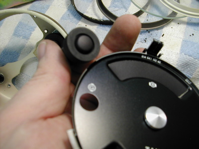
Posted by: 914forme Apr 23 2006, 08:15 PM
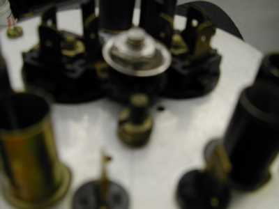
Next up we must remove all the light bulb tube holders. If you have not removed the light bulb sockets yet now i the time. Some might be stuck after 30 odd years, just use a pair of pliers and gentle twist them to loosen them up, the pull them out.
Here is how you remove the light bulb tubes, they are held in via a crimp that we can not recreate, so you must drill the crimp off. I am using a 3/4" drill bit mounted in my drill press. You can also use a dremel, or a hand file if you want. You just need to remove the metal crimp and that is all.
Attached image(s)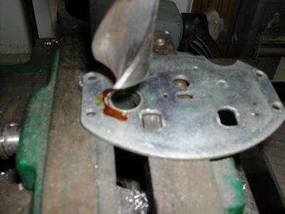
Posted by: 914forme Apr 23 2006, 08:19 PM
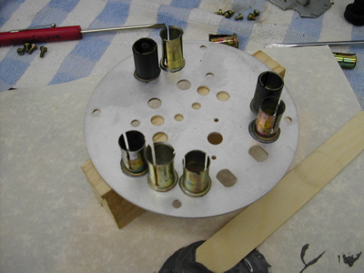
Now you just pull them out. You must now repeat this step until all these light tubes are removed from the old donor gauges.
Attached image(s)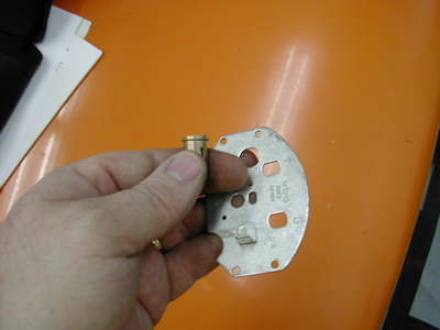
Posted by: 914forme Apr 23 2006, 08:20 PM
This is a good place for me to stop for the night.
Posted by: 914forme May 7 2006, 05:36 PM
Here is what happens when your bit grabs one of the post light thingy. Doah!!!
Attached image(s)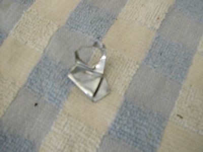
Posted by: 914forme May 7 2006, 05:42 PM
Now onto the cutting of the rear gauge face. There are two styles of gauge backs that you can be dealing with. The first is the early style. the second one is the late style they removed the extra top window. If you are using the late style you will need to drill out 2 extra holes for the backing plate mount. You will also need to tap these with a 3mm 0.5 tap. I suggest you do this before, you cut the back off.
Attached image(s)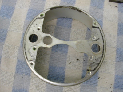
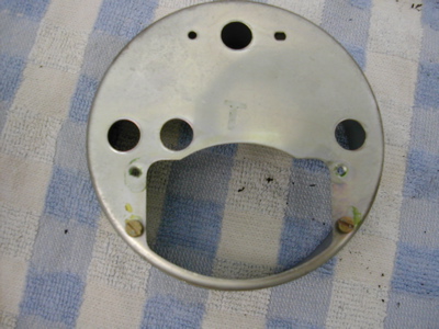
Posted by: 914forme May 7 2006, 05:46 PM
I like to test fit the gauge kit back onto the orginal gauge back, just to make sure it all will work. Just one simple step to make sure I don't screw up. Which I can do with ease.
Attached image(s)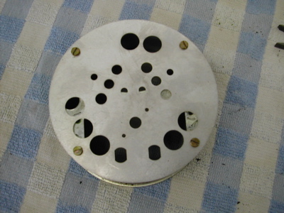
Posted by: 914forme May 7 2006, 05:48 PM
Next you draw out your cut lines. I happen to leave just a little of the roll over in from the sides to the back. Makes the gauge stronger - thou that 16 gauge metal should not go any where. Next up Destruction!!!!!!! 
Attached image(s)
Posted by: 914forme May 7 2006, 05:52 PM
Now it is simple you just cut away everything that is not a 904 gauge. 
I use three systems depending on my mood. First up shears. I use these to cut away the center bar.
Attached image(s)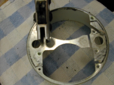
Posted by: 914forme May 7 2006, 05:56 PM
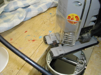
Now I used to use a hand nibbler like this, it was hard work, a pain in the  I now use a simpler method. But thats because I finally got a decent saber saw. So I now put a fine tooth blade and cut them out like this, a bench vice is required, I use the wood vice for this.
Attached image(s)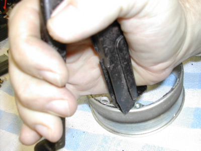
Posted by: 914forme May 7 2006, 05:57 PM
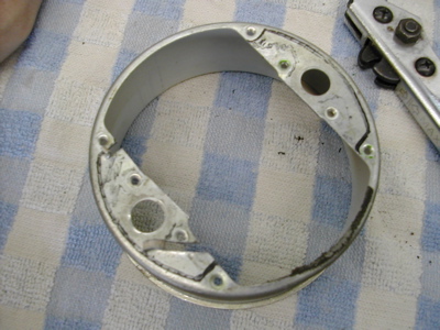
So when your done it should look like this.
Attached image(s)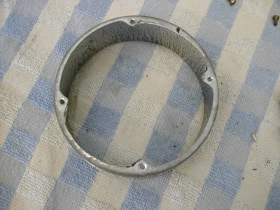
Posted by: 914forme May 7 2006, 06:01 PM
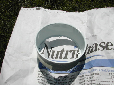
I once again test fit the back, just to make sure I didn't screw it up. Once everything is done, I do once set here that is a good idea. I paint the inner gauge surface white. Helps get the light to bounce around the gauge and makes it so it illuminates better.
Attached image(s)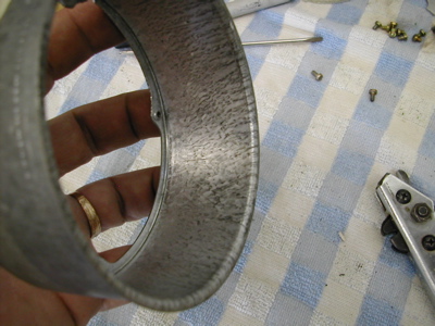
Posted by: 914forme May 7 2006, 06:40 PM
Next if you are lucky enough to find a late style fuel gauge you will have to make a templet. to drill the 4 other holes you will need. Make the pattern and mark your holes, here I am using one of my extra backs, I have. After that you need to drill the holes. The bigger holes are 0.247" the smaller holes are 0.160" and the largest outside hole is 0.268". Mark them with a transfer punch or a Sharpie and go to town.
Attached image(s)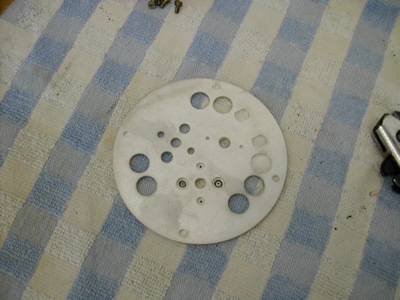
Posted by: 914forme May 7 2006, 06:41 PM
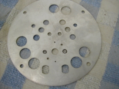
Now you need to test fit the light tubes.
Attached image(s)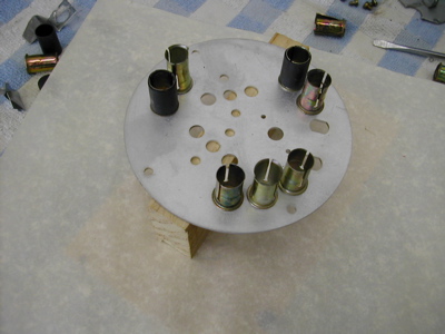
Posted by: 914forme May 7 2006, 06:45 PM
Mix up the epoxy, mine sets in 24 - 48 hours. You can use the 10 minute type, I just had this stuff around, and don't mind waiting for it to set, as long as you don't. I spin the tubes into the epoxy up to the shoulder. I then wipe the excess off on my mixing paper.
Attached image(s)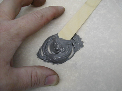
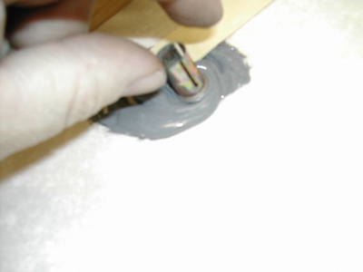
Posted by: 914forme May 7 2006, 06:48 PM
Next I spin them into the back to make sure they make full contact. And all done, notice I did step the tubes height. This will help you pull and put in the bulbs. And tis is where I have to stop for a couple days.
Attached image(s)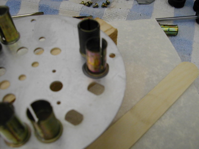
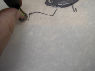
Posted by: 914forme Aug 8 2006, 03:52 PM
So next is line up the gauge face with all the parts, so you know where the idiot lights go.
I mark them with a pencil on the gauge back. It just makes life easier.
Attached image(s)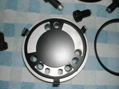
Posted by: 914forme Aug 8 2006, 03:53 PM
Next you add the adapter ( for lack of better term) for the idiot light tubes to the three holes you marked. You might have to file some of your epoxy away to get them to fit. You also need to add an adapter ring for the low fuel warning light. It is the hole to the left of the fuel gauge spade connectors. A picture on the next post shows this in detail.
Attached image(s)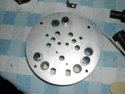
Posted by: 914forme Aug 8 2006, 03:57 PM
Next is more fun than you should legally be allowed to have. You have to add the old spade connectors back in for the old style fuel gauges - if you are using the later style - skip this step but you don't know what you are missing.
You take and hold the black plastic piece in the proper spot, add the heavy paper washer back onto the top of the spade connector, and then crimp the two side stubs, see that was easy. I split the paper washer, I will fix that with some insulating goo once I finished the soldering.
Attached image(s)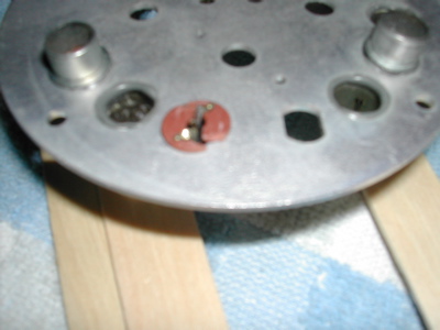
Posted by: 914forme Aug 8 2006, 04:04 PM
Next is the best part marking where you need to cut to get the idiot lights up and through the gauge faces. Rinse and repeat these steps 3 times. Then you cut around your pencil marks. I have a 1/2 in chassis punch I use to do this with, makes nice clean holes. But you can use a standard set of snips, or a nibbler to do this also. A file if you really wanted to, or a dremel if you have a steady hand.
Attached image(s)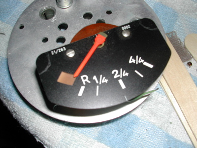
Posted by: 914forme Aug 8 2006, 04:08 PM
Now you mount a gauge , mount the idiot light tube, mount the next gauge, mount a tube, mount the third and mount a tube. With luck you won't have to adjust your cuts.
Attached image(s)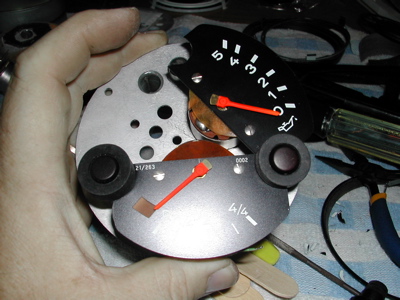
Posted by: 914forme Aug 8 2006, 04:10 PM
Next up fun with a hot piece of metal, and some melty stuff called solder. You have to solder the old fuel gauge leads onto the spade connector.
Attached image(s)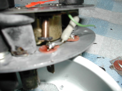
Posted by: 914forme Aug 8 2006, 04:14 PM
Wow that last close up shot was out of focus. I took photography lessons for Sir Andy.
We are getting close now!
You get to test fit the inner gauge face onto the gauges.
Note: I have one light tube off, just enough that it does not stay in the hole on the gauge face.
I will show you my solution to the gauge face issue. In the next installment.
Attached image(s)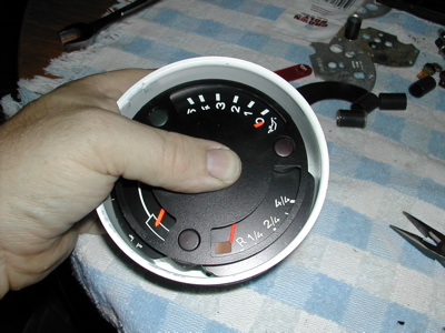
Posted by: 914forme Aug 8 2006, 04:20 PM
Only a few more steps to the finish of this project - now I just need to find the time. BTW, I have three ways to hold the inner face in the inner face in the proper orientation of the face.
1. the way the original directions say to do it. Clips epoxied to the side of the gauge, ouch. That was really a pain to do.
2. You cut out the original face and use its tabs to support the new one, in place this requires epoxy also. I will take pictures of this way.
3. I have come up with a better way, or at least I think it is better, we will see. See you next time.
I love cliff hangers!
Posted by: 914forme Aug 17 2006, 07:38 PM
Okay lets do it!
I told you I would show you my two favorite ways to do the face, number 1, you cut out the original face and use it to space your above the lights.
Just add a little of your fav epoxy to hold the two together and you might have to touch up a little around the outside edge.
Attached image(s)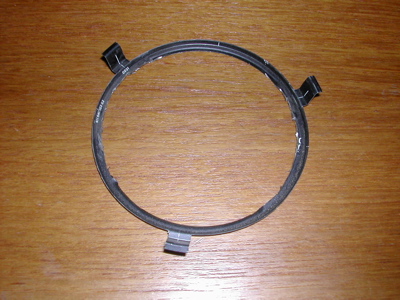
Posted by: 914forme Aug 17 2006, 07:45 PM
And for the cliff hanger!
This cures a bunch of ills, like my one light tube being out of place, it is a postive mechanical fastener, and it is so easy, wish I came up with it 10 years ago.
First you need to mark the center of the face, if you got one with out a hole. If your building one with a black center this might not work for you. Or it could, with a little camoflage work once you are done.
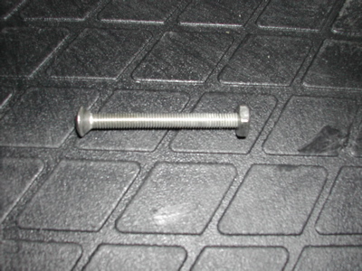
Next you drill it just a little smaller than the outer face of your counter sunk machine screw. Then you counter sink the face.
Next you drill the center of the back face, and here is the simple part you bolt it togther. Just use a rubber spacer ot keep the screw from grounding out any of the guage connectors.
Attached image(s)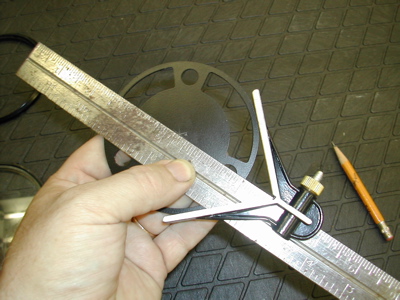
Posted by: 914forme Aug 17 2006, 07:48 PM
More pictures
Attached image(s)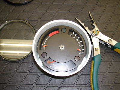
Posted by: 914forme Aug 17 2006, 07:55 PM
Again my Sir Andy school of photography is paying off!
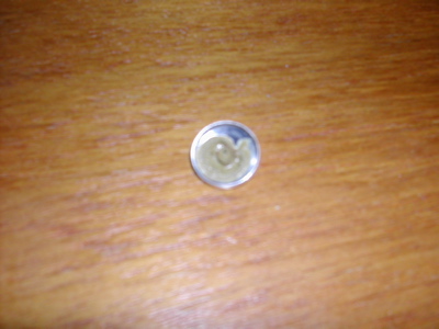
Next you need to cover that back woods engineering! If you want the black flat face, mix up a little filler and fill it , and paint it. Or do as I do, use a silver button, and paint it black, I like a profile change, adds a little depth and dimension to the gauge. For this one I needed a silver button, so that is what I did.
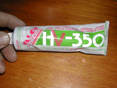
In the instructions it says to drill out the silver button. A little tip is the silver button is mounted on a steel rivet. You can gently pry the two apart. Use your fav glue and put it back on. I used Valco HV-350 It will glue about anything to anything, and is paintable if you get messy. Add a dab of glue and hide that screw!
There you go you will not know that screw was there now from the outside. 
Attached image(s)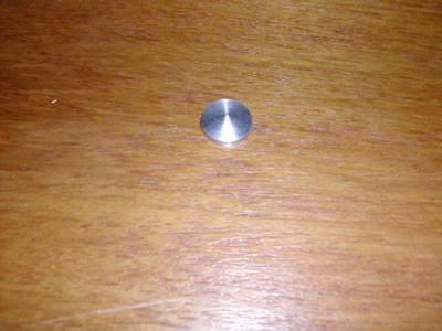
Posted by: 914forme Aug 17 2006, 08:02 PM
You might want to let that glue dry wheel before butting it up. the glue could outgas and cause a film to be created on the inner glass.
Next you add the intermediate gauge face. then clean the glass or plastic and add that. If-using glass, 100% isoperic (sp?) alcohol will clean it up really nice. Note: I am waiting on the outgas process to complete, but want to finish this post so, my glass is not clean.
Attached image(s)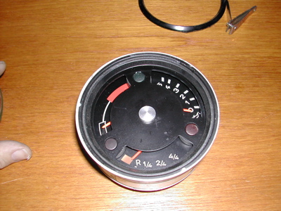
Posted by: 914forme Aug 17 2006, 08:08 PM
Next you snap the outer ring back onto the Gauge can. I use a brass punch, once done some paint will have flaked off, touch it up, you don't want rust. the rubber mount ring will cover up most of your pro paint job here.
Attached image(s)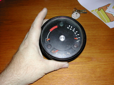
Posted by: 914forme Aug 17 2006, 08:10 PM
Thats all except putting it into the dash and wiring it up.
Now I get to go an grab a cold one! 


Attached image(s)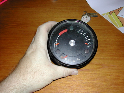
Posted by: JOHNMAN Aug 17 2006, 10:28 PM
Those look great. Almost as nice as mine.
I use the late fuel gauges in mine.
Attached image(s)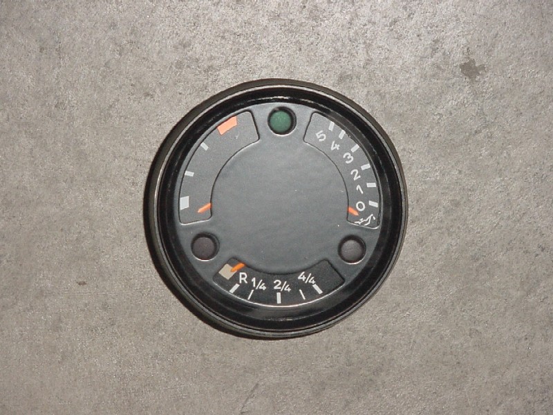
Posted by: Dave_Darling Aug 18 2006, 09:21 AM
Me, too, John. It was easy to use the late fuel gauge; I just transferred the same holes used for the other gauges to the lower location used by the fuel gauge. A bit of tracing paper helped, and of course I stuck it in a drill press to make the actual holes. It was a pretty easy modification of the "early fuel gauge" backplate that I got with my kit.
--DD
Posted by: PiperSpeed Dec 30 2014, 04:17 PM

Well here it goes the step by step instructions on how to build one of the kits. Since I helped do the original production run, back in the day, its been about 11 years ago since we did these. But there is interest in it so I will show you how.
Step one, the original kit. It included a gauge face, a backing plate and a ground lug. Also included instructions on how to do this, and some of the items where real PITAs to do. I will included some changes I do, and items that might make the installation a little easier.
Hi Steven,
Do you know where I can get one of these kits ?
Thanks,
Jan
Posted by: Steve Dec 30 2014, 06:57 PM
I bought mine from John.
http://www.914world.com/bbs2/index.php?showtopic=58970
Powered by Invision Power Board (http://www.invisionboard.com)
© Invision Power Services (http://www.invisionpower.com)