Printable Version of Topic
Click here to view this topic in its original format
914World.com _ 914World Garage _ Updated 2.0L D-Jet Vac hose layout - Late 74
Posted by: Jeff Bowlsby Oct 8 2006, 03:50 PM
The vacuum hose layout diagrams floating around did not reflect my late 1974 engine bay because the fuel vapor filter is mounted to the rear wall of the engine bay (different from early 1974 and before where it is on the fuel tank). So I made my own updated diagram. Everything correct as far as I know in cluding the nipple sizes and original hose colors, please let me know if you find any errors. Diagram and keynotes are below use them if you want.
The later cars have the fuel vapor filter in the engine bay too, but its bolted to the battery tray clamp. Conceptually, is that arrangement plumbed any differently?
Attached thumbnail(s)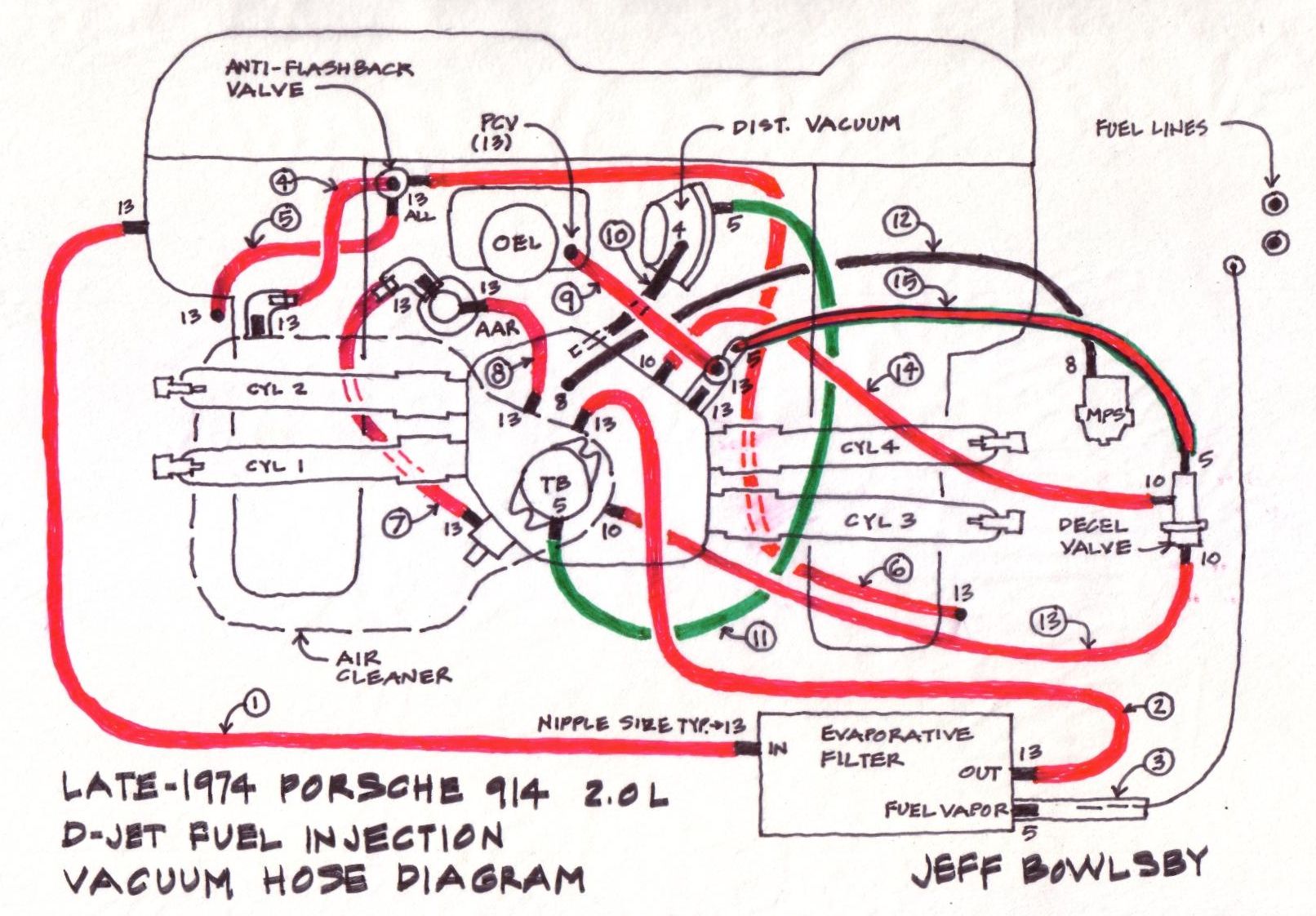
Attached image(s)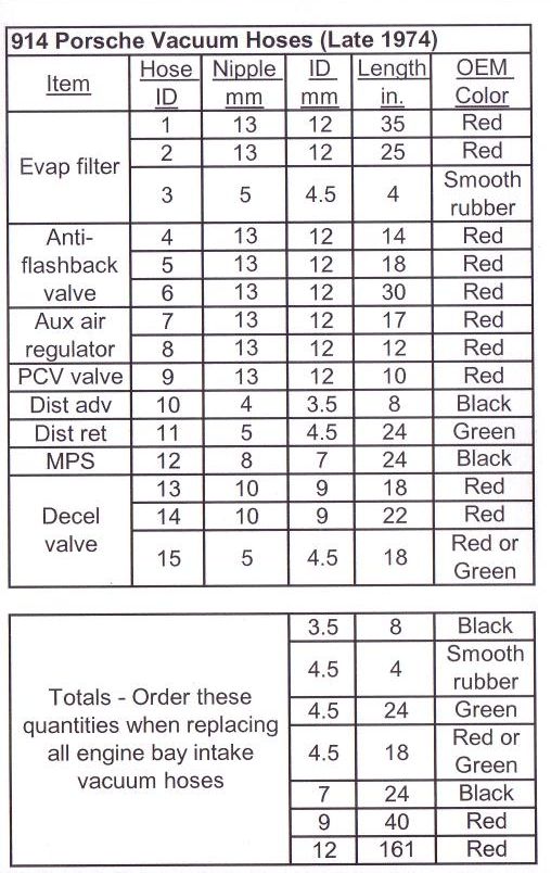
Posted by: wilchek Oct 8 2006, 04:48 PM
Jeff,
where did you get that chart with hose lengths or did you make that also
Posted by: Dave_Darling Oct 8 2006, 05:13 PM
Jeff, could we have permission to post a copy on the Bird site?
--DD
Posted by: Jeff Bowlsby Oct 8 2006, 05:27 PM
I made the chart of lengths and colors by measuring the hoses from my original 74 Bumblebee and comparing photos of several original 914 2.0Ls from late 74.
Dave...absolutely.
Posted by: Demick Oct 8 2006, 05:53 PM
Very nice Jeff!! 
Posted by: mihai914 Oct 8 2006, 07:26 PM

Very nice Jeff!!

Jeff, hose #10 for advance, is it connected or simply plugged on your diagram.
Also, anyone knows where to find those elbows and especialy that double outlet rubber piece for the decel valve and PCV valve?
Edit: Oh yes, it should be added to the classics.
Powered by Invision Power Board (http://www.invisionboard.com)
© Invision Power Services (http://www.invisionpower.com)