Printable Version of Topic
Click here to view this topic in its original format
914World.com _ 914World Garage _ Glimpse of Things to Come?
Posted by: Eric_Shea Dec 7 2006, 07:50 PM


Attached image(s)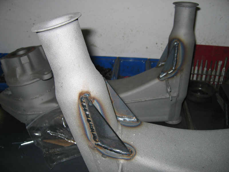
Posted by: Dan (Almaden Valley) Dec 7 2006, 07:52 PM
Looks pretty decent to me Eric 
Interesting reinforcement...something you plan on offering? 
Posted by: Eric_Shea Dec 7 2006, 07:57 PM
Mayyyyyyyyybe... 
These are just 1/2 of the equation. More to come.
This came out of a conversation Erik (with a "K") and I had last month. Many thanks to Ron for cutting and making these and exact fit. Funny how a piece of cardboard and the USPS can make things magically appear. 
Posted by: SLITS Dec 7 2006, 08:06 PM
I laugh at you not for your welding but because you are an Admin.
Posted by: George H. Dec 7 2006, 08:09 PM

I laugh at you not for your welding but because you are an Admin.
Don't laugh your next

Posted by: jimtab Dec 7 2006, 08:13 PM
To paraphrase the movie...."in the future all members will be admins."
Posted by: mikez Dec 7 2006, 08:15 PM
Why wait for Brad...we're here for you...... 
Posted by: SLITS Dec 7 2006, 08:19 PM
I laugh at you not for your welding but because you are an Admin.
Don't laugh your next
Oh threaten me not with such an exhaulted
title!Posted by: Series9 Dec 7 2006, 08:38 PM
I think you need a third piece. Otherwise, the strength of the rest of the assembly will simply cause the two pieces you added to bow outward under load. 914 trailing arms are very strong, you know.
Also, I found on my arrangement, that the 255s (on 17x9s) occupy the area of the modification. Thusly, that size wheel/tire would not fit on arms modified in this manner.
Attached image(s)
Posted by: George H. Dec 7 2006, 08:43 PM
I laugh at you not for your welding but because you are an Admin.
Don't laugh your next
Oh threaten me not with such an exhaulted
title!Oh, this is Slits, excuse me
what i meant was that,
Ron is the Next Admin
Posted by: Eric_Shea Dec 7 2006, 09:01 PM
Joe,
What do you think about another piece like this?

I realized that huge wheels might limit this. I measure my car with the GT flares and 8x15's and 225x60's with tons of room. That was my next question about the entire thing... how big can they go before they rub? The design was to keep that profile as low as possible. 
Posted by: Gint Dec 7 2006, 09:01 PM
Guy at work has a phrase for those kind of welds (not like I'm any better  ) "Pile'n up snowmen"
Posted by: Series9 Dec 7 2006, 09:34 PM
I think my idea is much easier to weld AND stronger.
As for size, I don't think 18s will fit on mine because the 17s will barely fit a pinky finger in that area. With your mod, I'm almost certain 17s will not fit.
Of course, the fit is from memory.
Let me see if I can get pics.....
Posted by: Aaron Cox Dec 7 2006, 09:37 PM
eric - where be your welding jig? LOL
yeah... doesnt the tire go there? will as stcok diameter tire interfere?
Posted by: Series9 Dec 7 2006, 09:39 PM
Here you go. Sorry it's ditry. Ferg hasn't been down recently. I exaggerated a bit, but I still think there will be issues with 17s:
Attached image(s)
Posted by: Series9 Dec 7 2006, 09:54 PM
Guy at work has a phrase for those kind of welds (not like I'm any better
) "Pile'n up snowmen"Eric, your welding is just fine. Maybe just a little more heat......
Posted by: Eric_Shea Dec 7 2006, 10:44 PM
Again, I made that profile rather low... I think it would work on your car. Look at the relationship to the brake line clip in the first picture and on your car. The gusset is not where your fingers are.
Absolutely. I designed them that way. These are "brakes"!

Did you say you're going to college?

Hey... got a special picture for my Lil'Buddy.

Posted by: Crazyhippy Dec 7 2006, 11:05 PM
how about both reienforcements? WILL be much stronger and minimal weight difference
BJH
Posted by: Racer Chris Dec 8 2006, 01:39 PM
I agree with Joe that it should have cap. I also think it should be one formed piece to cut down the amount of welding (warpage) and should be 14-16 ga sheet metal, no more.
Posted by: 914-8 Dec 8 2006, 02:08 PM
What kind of welder did you buy?
Posted by: Lawrence Dec 8 2006, 02:24 PM
Eric,
I like the welds... you've done good work.
Are you worried about stiffening up the arms too much? Personally, I'd rather have an arm fail than the suspension ear.
Posted by: Rand Dec 8 2006, 02:32 PM
Joe's suggestion is good. Welding that plate all the way across to box it is going to make it a lot stronger.
My thought is, why not cut a piece of tubing to fit and just weld one piece rather than three. Plus the rounded shape would be even stronger.
(EDIT: OOps, I see Chris sorta beat me to it... One formed piece. Again though, I think a rounded shape is better than a flat cap.)
Attached image(s)
Posted by: 736conver Dec 8 2006, 02:37 PM
Eric,
I like the welds... you've done good work.
Are you worried about stiffening up the arms too much? Personally, I'd rather have an arm fail than the suspension ear.
Thats what I was thinking. Where is the stress going to goto now and what will it do.
Posted by: Aaron Cox Dec 8 2006, 02:43 PM
maybe eric will sell suspension ear beef up kits too! 
Posted by: Eric_Shea Dec 8 2006, 08:35 PM
Thanks Chris. Actually... this looks like something you already did. I revisited the trailing arm thread today and saw a bunch of pictures in the middle of the thread that I missed... hmmmmmm. Not wanting to step on toes or reinvent the wheel.
I guess I'll just play with these for my car.
The idea was to have a fairly simple kit for the spirited driver/autocrosser. I'm also welding in two 1" tubes through the arm which I see now had been discussed in that thread as well. I know it's nothing new but, I was thinking of offering it as a service at around $395 a pair.
Posted by: Eric_Shea Dec 8 2006, 08:38 PM
I have the GT chassis to ear turnbuckles on my car. I didn't want to make these too beefy but solid enough were they wouldn't flex so much. Basically, I was shooting for a little more strength than the boxed arm kit without the weight.
Posted by: Eric_Shea Dec 8 2006, 08:39 PM
Lincoln 135
Posted by: john rogers Dec 8 2006, 08:42 PM
When I was spun into a curb in the race in Tijuana this summer at about 30 MPH or so, the are you are gusseting never was affected. The box section of the trailing arm collapsed giving the rear wheel about 45 degrees of toe in or until the tire hit the pivot area. When we pulled the bent arm off the bearing area was fine.
Posted by: Lawrence Dec 8 2006, 08:51 PM
John,
Are you the "John Rogers" that does the great repro windshield stickers?
If so, your input would be welcome in this thread:
http://www.914world.com/bbs2/index.php?showtopic=65245
If not... sorry to bother.
-Rusty 
Posted by: pete-stevers Dec 8 2006, 11:27 PM
what Brad might say....."it will crack at those welds.....i've seen it before"
Posted by: PRS914-6 Dec 9 2006, 12:23 AM
Before and after shots. Clears 245/45/16's with ease


Posted by: Eric_Shea Dec 9 2006, 09:53 AM
Excellent Paul,
I see you've been down this road. Any findings? Has the car hit the road since the mods?
Looks like this has been done (quite) a few times before then... I may proceed.
I'm still thinking of the two tubes vs. the boxing kit. I have the boxing kit on my arms now but it looks like the tube will do slightly more than the boxing kit for a few oz.'s vs. a few lbs.
From what I've read, the boxing kit weighs 3lbs. and will add nearly 40% in rigidity to the stock arm. Tubes would add over 50%.
Just trying to delve into a practical, real world application that won't cost an arm and a leg.
Thanks for the pics Paul.
Posted by: PRS914-6 Dec 9 2006, 11:22 AM
If I recall, it was Rich Johnson who suggested cross tubing the arms. I thought it was an excellent idea to prevent twist. Unfortunately I had picked up a set of the std arm kits on eBay dirt cheap so I went that route instead.
I know a lot of people frown on the reinforce kits but with 300hp and sticky 245 tires, I felt something should be done so I did what seemed appropriate for my build......time will tell
As far as the driving goes.....I test drove the car before it went to paint (no doors, hoods, or windshield). I wanted to make sure there were no major mechanical problems to deal with after the exterior was painted and the engine needed to be trial run before warranty runs out.
Bottom line....couldn't check the arm stiffness but it did scare the shit out of me....
Posted by: Eric_Shea Dec 9 2006, 02:06 PM
I think they're great. 3lbs. and a 40% stiffer arm. Unless you're on an all out diet that's a pretty easy way to stiffen up an arm
Posted by: Eric_Shea Dec 9 2006, 06:20 PM
OK... had a little time for "me" this afternoon.
Got some holes drilled and some 1" tube welded in. 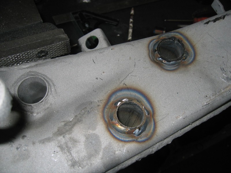
Note to self... hire out the hole drilling. 

Now for a little powdercoating
Posted by: Eric_Shea Dec 9 2006, 06:33 PM
Both a stock arm and this arm weigh in at 15.8 lbs. on a digital scale.
Posted by: SirAndy Dec 9 2006, 08:17 PM
OK... had a little time for "me" this afternoon.
you're getting there ... all the ones i have seen done this way had at least one tube going top/bottom. seems like that way you would get even better results, working in both planes, not just one ...
 Andy
AndyPosted by: LvSteveH Dec 10 2006, 11:29 AM
Both a stock arm and this arm weigh in at 15.8 lbs. on a digital scale.
Note to self, don't trust Eric's scale
Posted by: Brett W Dec 10 2006, 12:48 PM
hijacked:
Here is a good example, albeit extreme, of what happens to an swing arm when radically loaded through the tire contact patch.
Attached image(s)
Posted by: So.Cal.914 Dec 10 2006, 01:02 PM
A BFH and some bondo..... 
Posted by: Brando Dec 10 2006, 01:12 PM
^^^ Looks like the area being reinforced in Eric's photos didn't really need it...
![popcorn[1].gif](style_emoticons/default/popcorn[1].gif)
Posted by: JPB Dec 10 2006, 01:51 PM
Did ya do a torsion test on this gusset setup?
Posted by: Eric_Shea Dec 10 2006, 02:42 PM
Well, even a guy like you can see what the gussets did for that arm
Seriously, the gussets aren't to prevent mass failure as in John Rogers case or the arm that Brett is showing. They are there to prevent flex while driving the car. This was part of the conversation I had with Erik Madsen, that area does flex. I felt that even the simple gusset arrangement I've added will help reduce that flex tremendously... that's what gussets are for.
I think I've accomplished my goal. A control arm that is 40-50% more ridgid than stock without the weight penalty.
Note to Steve... don't you have a running car to purchase to take to an event, tear apart so you can't make the event, rebuild then sell???

Jim (Stratplayer) was just here and witnessed the scale first hand... so THERE!

Posted by: Eric_Shea Dec 10 2006, 03:05 PM
Brett, just the tire contact patch caused that control arm to bend down at a 45 deg angle? Or, was it the wheel coming in contact with a curb. That would be some serious grippage...

Posted by: LvSteveH Dec 10 2006, 10:02 PM
Note to Steve... don't you have a running car to purchase to take to an event, tear apart so you can't make the event, rebuild then sell???
Jim (Stratplayer) was just here and witnessed the scale first hand... so THERE!
Actually, the car's back running again, although still on jackstands, and I'll never be able to sell it, I'm in too deep. Should be pretty neat when it's finished though. I'd like to have it going for spring.
Posted by: Brett W Dec 10 2006, 10:06 PM
Since my big wing on the back generates 10K lbs of, Of course it was through the tire contact patch. You ought to see how powerful my car is.
Actually that was a curb applied through the lower sidewall, upon impact. Yes it was pretty radical example but the arm didn't really bend in laterally, it actually twist.
Posted by: Eric_Shea Jan 27 2007, 02:18 PM
Stratplayer was gracious enough to apply the powdercoating. 
I'm happy. Here's my line of thought.
1. From measurements I've seen these should be 50% stiffer than stock.
2. There is literally no measurable weight penalty.
3. Could they be stiffer? Yes.
4. Should they be stiffer? There's a lot of arguments against that.
This and a decent set of bushings will net a rear control arm assembly that is better than 90% of the 914's that are currently out there.
Here's a few pics. I've yet to press out the old bearings (I left them in to powdercoat them).
Attached image(s)

Posted by: Aaron Cox Jan 27 2007, 03:26 PM
sweet!
what if you ran one at a 45 degree angle.. inner right bottom to upper left top etc?
oh wait... too much geometry LOL
looks good dude
Posted by: So.Cal.914 Jan 27 2007, 03:58 PM
Cool, idea stolen for mine.
Posted by: sean_v8_914 Jan 28 2007, 11:48 AM
96.75% of all statistics are made up on teh spot
what measurement was made to determine percent of improvement?
what club member did the rear arm flex measurement fixture? I remember a thread about this
Posted by: Twystd1 Jan 28 2007, 04:15 PM
Chris Foley was in that other thread.
He apparently has figured out how to strengthen the arm with very little weight.
Now where the hell is that thread...???
I Think he opened the arm up and boxed it internally. Then welded a patch over it.
Thats my memory of that thread. Could be wrong.
I can't find it.
C
Posted by: jd74914 Jan 28 2007, 04:57 PM
Its only on the 914club now :shrug:
Since Brad has no pictures up they are gone though.
http://www.914club.com/bbs2/index.php?showtopic=42873&hl=weak
Posted by: JPB Jan 28 2007, 06:34 PM
Any extra stiffyness is good stiffyness. Thanks for sharing and will probably hole saw a couple of tubes in on mine some time as well as the goossetes. 
Posted by: roadster fan Jan 28 2007, 09:50 PM
IIRC, Chris Foley cut the arm in half perpendicularly. He then welded a piece of 1/8" plate between the two. I think he said the kerf on the cut was about 1/16" so he only made the arm 1/16" longer by adding the plate. I thought I had the pics but couldn't locate them....sorry
Jim
Posted by: roadster fan Jan 28 2007, 09:56 PM
I think this is how he did it....
Posted by: Lawrence Jan 29 2007, 10:10 AM
Its only on the 914club now :shrug:
Since Brad has no pictures up they are gone though.
http://www.914club.com/bbs2/index.php?showtopic=42873&hl=weak
Older threads are in the same place... updated domain name.
http://www.914world.com/bbs2/index.php?showtopic=42873
Hope this helps,
Rusty
Posted by: Travis Neff Jan 29 2007, 10:26 AM
All the pictures had been removed from that thread by the poster.
Posted by: Spoke Apr 29 2007, 10:29 AM
I used Aaron's idea of supports on 45 degree angles. Used two 3/8 inch rods crossed in 2 places.
Any ideas if this will help the flex?
Spoke
Attached image(s)

Posted by: JPB Apr 29 2007, 10:58 AM
For that to work really good, one would have to weld the two rods together where they cross in the center.
If we cut the box lengthways through the center and added a 1/8th plate that goes from one side to the other in the same plane as the bolt welded solid on all the way around, it would make a huge increase in stiffness. If the bolted end had a flare like a single gusset similar as above but just down the center and welded solid, it would be amazing.
Posted by: SirAndy Apr 29 2007, 05:15 PM
Its only on the 914club now :shrug:
chris foley deleted all his posts here after the split ...
Andy
Posted by: JPB Apr 29 2007, 08:31 PM

 We just need to grow up and gitallong dangnambit! Crap that means me also
  Booooooooooooooring.
Does anyone have a real life for sale, I need a real life here.
Powered by Invision Power Board (http://www.invisionboard.com)
© Invision Power Services (http://www.invisionpower.com)