Printable Version of Topic
Click here to view this topic in its original format
914World.com _ 914World Garage _ The Decel Valve Hose Diagram for the 2.0L Djet is Wrong
Posted by: pbanders Jan 20 2007, 05:50 PM
I made some postings before the "great split" about the decel valve where I asked questions on how it worked. I figured it out, and now I understand why I was confused.
If you look at the hose diagram Dave Darling made for the 2.0L, and I also believe it's the same way in Jeff Bowlsby's diagram, they show the "side" port to the decel valve connected to manifold vacuum, and the larger "end" port connected to the air box. George Hussey of Automobile Atlanta posted a diagram in a thread on the '74 hose configuration that showed it connected oppositely. Which one is right?
Turns out George's diagram is correct. As I complained in the earlier thread, I couldn't see how the valve worked when hooked up the way Dave and Jeff's diagrams showed. Not their fault - it's shown that way in the Factory Workshop Manual (see the FI manual, page 0.1-1/3, page 0.1-2/1) and all the other references I've seen. The problem is that if you pull the same manifold vacuum on both the side port (which is on one side of the internal diaphragm) and the skinny end port (which is on the other side of the internal diaphragm), there's no pressure differential to open the valve.
It didn't occur to me that the majority of diagrams might be wrong until I saw George's diagram. Now it makes sense - the valve works to limit vacuum if connected so that the large end port is on manifold vacuum and the side port is connected to the air box. Why? Because in this configuration, only the control side of the diaphragm is initially connected to vacuum (actually, it's slightly different from that - a very small area on the other side of the diaphragm is under vacuum where the valve seat for the large end port is located). Once the vacuum is high enough to overcome the internal spring resistance, the valve opens and the intake manifold vacuum is limited.
I tested three different decel valves on the bench, two used 914 valves, and a NOS valve I picked up on Ebay for a Volvo D-Jet application. I used a universal plastic tee connector to connect my hand vacuum pump to both the control port and either the large end or side ports of the valves. In each case, if I connected vacuum to both the control port and the side port (same vacuum across both sides of the diaphragm), the valve never opened up to 25 inHg of vacuum. If I connected the vacuum to both the control port and the end port (vacuum differential across the diaphragm), then at an onset vacuum, the valve opened, and I could not pump to a higher vacuum level - the vacuum was limited, as the valve is supposed to do.
Both of my 914 decel valves had been "adjusted", so I had no idea of what the correct onset vacuum should be. I recently had my motor rebuilt and did some manifold vacuum level testing. Fully warmed up, at idle, I am running about 10 to 12 inHg of manifold vacuum. If I rev the motor to 3500 rpm and snap the throttle shut, I see a maximum of about 22 inHg of manifold vacuum. The decel valve for the Volvo still has the factory paint mark on it and hadn't been tampered with. Measurements on that valve showed an onset of about 15 inHg. Seemed like a good number, so I adjusted my valve to that level and reinstalled it.
Now, when I test it as shown in the Factory Workshop Manual, where you open the throttle to 3500 rpm and snap it shut, you can feel it pull vacuum when the valve opens. I haven't had time to drive it around much since then (working on other problems), but as soon as I do, I'll report on any issues. I may increase the onset vacuum to 18 inHg, as when my motor is cold, it develops about 15 inHg at idle, about the same as the decel valve, and I don't want it to act as a leak.
Posted by: Mid_Engine_914 Jan 20 2007, 06:02 PM
And that, sir, is why you’re the king of D-Jet.
Posted by: reverie Jan 20 2007, 06:12 PM
[QUOTE] George Hussey of Automobile Atlanta posted a diagram in a thread on the '74 hose configuration that showed it connected oppositely. Which one is right? Turns out George's diagram is correct.
Could you add George's diagram to this thread, please?
Thank you. 
Posted by: computers4kids Jan 20 2007, 06:17 PM
Hmm!
Attached thumbnail(s)
Posted by: StratPlayer Jan 21 2007, 01:48 PM
This should be posted in the classic thread
Posted by: bperry Jan 21 2007, 09:07 PM
Why not put a direct link to the diagram in the "Info" section,
since posts about hose routing pop up every now and then.
--- bill
Posted by: type4org Jan 22 2007, 03:30 AM
With the decel valve connected the wrong way, what would be the symptoms? Does it change anything apart from lowering emissions?
Posted by: pbanders Jan 22 2007, 09:51 AM

With the decel valve connected the wrong way, what would be the symptoms? Does it change anything apart from lowering emissions?
When the decel valve doesn't work, your intake manifold vacuum level is unrestricted during overrun (throttle closed, car moving) conditions. With the clutch released, you'd get stronger engine braking, with the clutch engaged, your engine would drop to the idle condition more rapidly. Enhanced engine braking is one of the reasons many people removed their decel valves. Having the engine drop to the idle condition more slowly seems to help with idle stability in some cars.
Posted by: type4org Jan 22 2007, 09:56 AM
When the decel valve doesn't work, your intake manifold vacuum level is unrestricted during overrun (throttle closed, car moving) conditions. With the clutch released, you'd get stronger engine braking, with the clutch engaged, your engine would drop to the idle condition more rapidly. Enhanced engine braking is one of the reasons many people removed their decel valves. Having the engine drop to the idle condition more slowly seems to help with idle stability in some cars.
Thanks Brad. I'll take a closer look at mine (a '76) to make sure it's correct. I have a symptom where engine speed falls very quickly with the clutch depressed, it falls way below the idle level and then recovers. It's a bit of an annoyance, makes me worry that the engine may just quit every time I coast towards a stop.
Posted by: Jeff Bowlsby Jan 24 2007, 11:47 PM
So I get back from vacation to find this Brad... 
Actually I have been thinking about this too, lately. I was only recently given the Elfrink book and it has lots of great text and photos about early D-jet systems, info I have not seen elsewhere. It also includes the following page on the decel valve...with an explanation...see the text for how they say the decel valve works and notice their hose layout and the airrows marking the airflow path.
Reading through the recent testing I am a little confused by terminology and I am sure I am misunderstanding some things. Can you describe the purpose of each port? Which is the 'control' port? Is there a diagram you could post showing the internal workings of the valve? All three of my 74 2.0L 914s have been/are connected per the 'other' diagrams and my idles have been rock steady. Willing to try swapping hoses for the new configuration for grins, but cannot get to it until this weekend.
Some observations and thoughts:
Point 1 - Regardless of the correct hose layout, 2 of the three hoses are connected to the intake air plenum and I think they both read the same vacuum pressure of the intake manifold system at all times (which varies with engine speed). These two hoses are of different IDs, yet the vacuum pressure they transmit to the decel valve is the same. What is the significance of the different ID tubings, in the actual pressure seen by the valve? Could it be that while the pressure is the same, the air VOLUME transmitted through the smaller and larger tubing is different, resulting in a short time pressure difference at the valve diaphram before equilibrium is reached? This pressure difference would reduce to zero as the engine decelerates to idle speed.
Point 2 - The third hose supplies filtered intake air at a reference 0 vacuum pressure (atmospheric) at all times, this hose could be left off, except that it provides filtered air which is better for the engine than non-filtered air, the vacuum signature and other effects should be the same.
Attached thumbnail(s)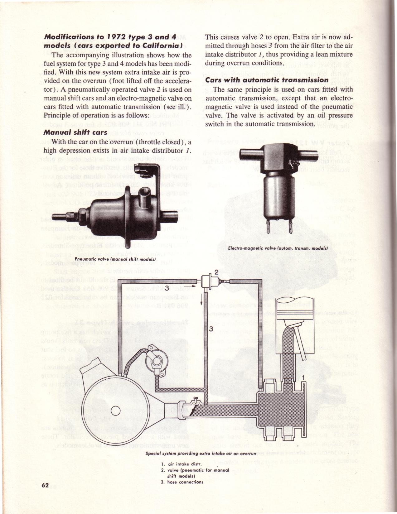
Posted by: pbanders Jan 25 2007, 09:49 AM
So I get back from vacation to find this Brad...
Actually I have been thinking about this too, lately. I was only recently given the Elfrink book and it has lots of great text and photos about early D-jet systems, info I have not seen elsewhere. It also includes the following page on the decel valve...with an explanation...see the text for how they say the decel valve works and notice their hose layout and the airrows marking the airflow path.
Hey, hope your vacation was good, and thanks again for sending me that alternator harness so quickly!
Actually, Elfrink does not say how the decel valve WORKS - instead, he simply says "it opens" - he doesn't tell us WHY it opens, based on its internal construction and the vacuum signals it sees. This is the crux of the problem, because once you understand how the valve actually works, then it is clear that connected as is shown in Elfrink's diagram (which is lifted from either a VW or the 914 factory workshop manual), it cannot do what it is supposed to do.
Reading through the recent testing I am a little confused by terminology and I am sure I am misunderstanding some things. Can you describe the purpose of each port? Which is the 'control' port? Is there a diagram you could post showing the internal workings of the valve? All three of my 74 2.0L 914s have been/are connected per the 'other' diagrams and my idles have been rock steady. Willing to try swapping hoses for the new configuration for grins, but cannot get to it until this weekend.
I don't have a diagram showing the internal workings of the valve, someone was supposed to send me one so I could cut it open, but I never received the valve. The three I have are in perfect condition, I don't want to sacrifice them. The internals are similar (but not the same) as the fuel pressure regulator, with the difference being that the chamber behind the diaphragm is ported in the decel valve.
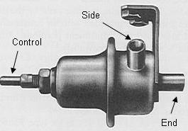
Here's a diagram with the ports labeled as I describe above:
Regarding the points you make about how you think the valve works in the configuration you show in Elfrink's diagram, rather than debate them point by point, I suggest you first do the experiment, which is the procedure described in the factory workshop manual (and copied in the Clymer and Haynes books) to verify the decel valve is working. Connect it as shown in Elfrink's diagram, pull the hose off of the air box, put your thumb over the open end of the hose, and open the throttle to 3500 rpm, then abruptly let it snap shut. If your decel valve is working, you will DEFINITELY feel vacuum when the valve opens. I don't think you'll feel a thing. Now, reverse the large hose connections that go to the "end" and "side" ports, and repeat. Assuming your valve hasn't been jiggered with so that the onset point is too high, you'll feel the vacuum pull when the valve opens. If not, check the valve's adjustment by removing it from the car, and using a hand vacuum pump to pull an increasing vacuum on the "control" port while blowing through the valve. It should open at about 16 to 18 inHg, if not, use the adjuster to set it.
I've done this with three different decel valves (2 used, 1 new) on both my car and on a bench setup I made, and they act just as I described above. If you find yours acts differently, we'll have to figure out why. One difference between our setups is that my plenum does not have the stacked vacuum elbow, as my plenum is physically identical to the 2.0 plenum but has different ports, a 5 mm and a 9 mm port, instead of a 9 mm and 12 mm port. I've got the "control" line of the decel valve connected to the 5 mm port, and I've got a tee connector on the 9 mm port that supplies vacuum to both the "end" port of the decel valve and the PCV valve. I will note that the stacked vacuum elbow is a part that is specific to the 914, and other T3 and T4 engines with decel valves lack the stacked vacuum elbow configuration (e.g. look at the Elfrink diagram for an example), indicating it is not essential to the functioning of the valve.
Let us know what you find out. If what I've discussed here is wrong, I want to understand why so we can figure this thing out.
Posted by: John Jan 25 2007, 02:11 PM
I've been reading this thread and I have a question.
Please correct me if I am wrong in my understanding of what you wrote.
The Decel Valve is a pneumatically controlled one-way check valve.
Flow is only permitted one direction when the signal line goes high (16-18" Hg).
The flow through the valve would introduce ambient air (from the air cleaner) into the manifold (below the throttle valve) any time that the manifold has a vacuum of 16-18" HG. Flow direction is in the SIDE and out the END.
This would limit the vacuum that the MPS would ever see, and introduce a controlled vacuum leak until 16-18" Hg vacuum is reached.
Am I understanding this correctly?
Posted by: sean_v8_914 Jan 25 2007, 03:07 PM
this is a highjack
I would like to publicly thank Jeff and Brad for their efforts. the availability of their info has converted me and many others to FI preservation. although I do not understand its function as well as they do, I am fairly proficient at troubleshootong 914 FI. Im always willing to help the San diego guys troubleshoot their FI cars (with the help of Brad and Jeff
thanks guys!!!
Posted by: pbanders Jan 25 2007, 04:15 PM
I've been reading this thread and I have a question.
Please correct me if I am wrong in my understanding of what you wrote.
The Decel Valve is a pneumatically controlled one-way check valve.
Flow is only permitted one direction when the signal line goes high (16-18" Hg).
The flow through the valve would introduce ambient air (from the air cleaner) into the manifold (below the throttle valve) any time that the manifold has a vacuum of 16-18" HG. Flow direction is in the SIDE and out the END.
This would limit the vacuum that the MPS would ever see, and introduce a controlled vacuum leak until 16-18" Hg vacuum is reached.
Am I understanding this correctly?
Yes. The point of debate is "what is the flow direction?". I say it's as you put it, in from the "side" port, and out the "end" port. I've verified on a bench setup that the valve operates this way, limiting vacuum to a setpoint value when vacuum is simultaneously applied to the "end" and "control" ports. I've also verified that if I simultaneously apply vacuum to the "side" and "control" ports, the valve never opens up to the maximum vacuum level I could attain with my hand pump (about 25 inHg). These results held true for three different decel valves I have. I also have verified that when I install the decel valve in my car, and connect it such that manifold vacuum is applied to the "end" and "control" ports, that when I snap the throttle shut from 3500 rpm, a strong vacuum signal can be felt on a hose connected to the "side" port, which agrees with the testing procedure for the valve from the factory workshop manual. I've also verified that if I connect manifold vacuum to the "side" port and repeat the same test, no vacuum signal can be felt on a hose connected to the "end" port. I also described that I'm not using a stacked vacuum elbow as per the factory configuration.
In an earlier thread, I asked others to try this test on their cars, one person responded and said that when manifold vacuum was connected to the "side" port, like me, they didn't feel a vacuum signal. I'd like for others to try this test, especially those with a stacked vacuum elbow in place. These cars are tricky - there's still a chance that I'm wrong about the "correct" vacuum hose configuration.
Posted by: pbanders Jan 25 2007, 04:17 PM
this is a highjack
I would like to publicly thank Jeff and Brad for their efforts. the availability of their info has converted me and many others to FI preservation. although I do not understand its function as well as they do, I am fairly proficient at troubleshootong 914 FI. Im always willing to help the San diego guys troubleshoot their FI cars (with the help of Brad and Jeff
thanks guys!!!
Thank you - I hope the discussions here aren't too confusing!! We're all just trying to figure out this crazy car and solve those annoying idle and drivability problems that clog the forum. I'm sure in another 50 years we'll get it all right.
Posted by: pbanders Jan 25 2007, 07:21 PM
Short update: I have a branched vacuum elbow in my parts box. I did a bench test where I used the elbow to supply vacuum to the decel valve under test. Using the branched elbow made no difference in the results - the valve only limited vacuum when the connection was to the "control" port and the "end" port, not the "side" port as most vacuum hose diagrams show.
When I get my car back from the shop (who knows when), I'll rig up a setup so that I can do the same test on the car to see if the results are the same under dynamic vacuum conditions.
Posted by: Jeff Bowlsby Jan 25 2007, 08:34 PM
Kudos Dr. Anders.
Well I studied those decel valve cadaver photos on the train ride home tonight...1 hour...still doesn't make complete sense to me, need better pics. I can make some sense of the upper half of the valve, but the lower end and small spring and other parts are still a mystery. Scalpel please.
Did you notice the small dark needle valve part lurking in the shadows of the opened valve? Does the red flex diaphragm have a small metering hole in its center or is that just a dirt smudge? Somehow I imagine that the flex diaphragm and the metal stop plate create a pressure differentially-operated valve that operates the needle valve, regulating intake air entering the side port, which then exits the big end port to feed the air plenum on decel, but I do not understand the mechanics yet.
I also swapped the big end and side hoses for my 20 minute cross-town jaunt home from the train station tonight. I noticed that the engine decel rate slowed down some over what I have always known and personally liked it. Was not a huge difference, only slightly noticeable, the decel rate was maybe 10-20% slower at most. I have not tested what my activation pressure differential calibration is yet.
I think I will keep it this way and change my hose diagram. How could all those diagrams be wrong for so long?
Posted by: John Jan 25 2007, 09:09 PM
Ummm, because nobody ever checked?
It seems to me that if this valve does what I am hearing, that it limits the maximum vacuum of the intake plenum/manifold to the set pressure of the decel valve.
Did all the D-Jet setups (on other vehicles/makes) have the decel valve?
What is manifold pressure (I know it's a vaccuum) at idle?
I would assume that the decel valve would be set to activate at a greater vacuum than you would have at idle. Hence the term decel valve.
Posted by: Bleyseng Jan 25 2007, 11:09 PM
around 15hg at idle on a stockish motor IIRC
Posted by: John Jan 25 2007, 11:20 PM
Then it would make sense to have the decel valve set for 16-18"Hg. It would stay closed at idle and only open during over-run conditions (deceleration).
Posted by: Dave_Darling Jan 25 2007, 11:23 PM
Did all the D-Jet setups (on other vehicles/makes) have the decel valve?
Not even all of the 914 D-jet setups had one. If you check an early 70, such as the one the 1.7 diagram on our site was made from, you'll find there is no Decel Valve.
--DD
Posted by: RustyWa Jan 25 2007, 11:56 PM
I wrote this info down long ago, but the deceleration valve in my old car, which was a '75 2.0L, would start to open at 18" Hg vacuum as well. If I remember correctly it opened quite fast.
Posted by: pbanders Jan 26 2007, 08:37 AM
Ummm, because nobody ever checked?
Even though I've got a some data that indicates that the diagrams are wrong, I'm still not 100% convinced, until I hear from a few more people that their decel valve works when connected as I've described. I've been burned before.
If it turns out to be true, my guess is that it's probably traceable to a single diagram being wrong 35 years ago. It got copied, that diagram got copied, etc. As you say, nobody went back and checked.
When people hooked it up as shown, and actually checked to see if a vacuum was present at the hose when snapping the throttle shut, they didn't feel a vacuum signal. Instead of tracking down the reason, they said "it must be bad" or "that stupid thing isn't needed, anyway", and didn't investigate further.
It seems to me that if this valve does what I am hearing, that it limits the maximum vacuum of the intake plenum/manifold to the set pressure of the decel valve.
Another name for the decel valve is "vacuum limiter". It prevents the manifold vacuum from exceeding a setpoint value. As others in the past have suggested, it also may contribute to the longevity of the MPS, by preventing high vacuum stress on the full-load diaphragm and the bellows.
Did all the D-Jet setups (on other vehicles/makes) have the decel valve?
No, it was an emissions add-on in later years. D-Jet always was a work in progress.
What is manifold pressure (I know it's a vaccuum) at idle?
I just got my engine rebuilt, and took some measurements recently. When cold, manifold idle vacuum is about 15 inHg, dropping to about 12 inHg when fully warmed up.
I would assume that the decel valve would be set to activate at a greater vacuum than you would have at idle. Hence the term decel valve.
Exactly. When the throttle is closed, and the car is moving in gear with the clutch out, the condition is known as "overrun". Manifold vacuum can exceed 20 inHg in overrun. The decel valve limits the vacuum to a value a few inHg more than the idle condition.
Posted by: pbanders Jan 26 2007, 10:59 AM
Kudos Dr. Anders.
Well I studied those decel valve cadaver photos on the train ride home tonight...1 hour...still doesn't make complete sense to me, need better pics. I can make some sense of the upper half of the valve, but the lower end and small spring and other parts are still a mystery. Scalpel please.
(other comments snipped...)
The pics Jeff is talking about are at:
http://www.914world.com/bbs2/index.php?showtopic=8803&hl=
Thanks to Rod for posting these. They're good, but not enough to figure out how the thing works exactly. I spent about 20 minutes last night using a small light and looking in the side port of a valve I had as I opened and closed it, and as you say, there appears to be more going on at the valve seat. The basic operation is pretty simple - you pull a vacuum on the skinny control port, and something inside that's snugged up against the top port tube moves and the valve is open. Exactly what's moving is not clear, I'll need to open up a valve to look at it more closely. I'm still waiting to get a sacrificial valve to do this with.
I also swapped the big end and side hoses for my 20 minute cross-town jaunt home from the train station tonight. I noticed that the engine decel rate slowed down some over what I have always known and personally liked it. Was not a huge difference, only slightly noticeable, the decel rate was maybe 10-20% slower at most. I have not tested what my activation pressure differential calibration is yet.
So, it looks like your decel valve started working when you reconfigured it, too. And you have the branched vacuum elbow, so that's one more item out of the picture.
I think I will keep it this way and change my hose diagram. How could all those diagrams be wrong for so long?
Give it just a bit more time before you change your diagram. I'd like to take a valve apart and fully understand its operation, and get some more owners to weigh in with results from their cars.
Posted by: pbanders Jan 26 2007, 11:54 AM
Jeff, after reading your comment about the "needle valve", I looked at the picture and I think I know how this thing works. If you look at the small spring, on one end, you'll notice there appears to be a disc. That's the valve seat. The small spring goes over the tube from the "end" port, and the disk covers the end of the tube when the small spring is compressed. It gets compressed by the diaphragm, which pushes on the back of the disk with the dark pin you can barely see in the picture. That pin goes into the hole in the plastic part in the middle of the large plate, and is pushed by the diaphragm. The purpose of the large plate is to relieve stress on the diaphragm when the valve is closed. The large spring pushes the back of the diaphragm up against the plate when there is no vacuum applied to the valve. When vacuum greater than the setpoint value is applied, the diaphragm moves, the pin slides back, and the valve seat moves away from the end of the tube, opening the valve.
When I open one up, I'll verify this.
Posted by: John Jan 26 2007, 12:26 PM
There must also be a mechanism to prevent flow in one direction, or it would work regardless of big hose termination.
Posted by: pbanders Jan 26 2007, 12:54 PM
There must also be a mechanism to prevent flow in one direction, or it would work regardless of big hose termination.
True, and that's the very issue we're discussing. From what I can see of the internal construction of the decel valve, it would be impossible for there to be air flowing from the large "end" port, to the "side" port. Why? Because for this to happen, you would need to connect the intake manifold hose to the side port, which would mean that for all values of manifold vacuum, there would be no pressure differential across the diaphragm, so it would never move. If you reverse the connections, then only the small annular area of the valve seat would be under vacuum, the majority of the diaphragm would be at atmospheric pressure, and the valve would open when it reaches the setpoint value.
Posted by: type47 Jan 26 2007, 01:03 PM
Another name for the decel valve is "vacuum limiter". It prevents the manifold vacuum from exceeding a setpoint value. As others in the past have suggested, it also may contribute to the longevity of the MPS, by preventing high vacuum stress on the full-load diaphragm and the bellows.
i'd like to hear more about this. if this is so, i'll re-install the decel valve, following the corrected diagram of course
Posted by: rhodyguy Jan 26 2007, 04:22 PM
jeff, when you say the rate was 10-15% slower, do you mean for the engine to come to a steady idle at a stop? we're talking seconds right?
k
Posted by: Jeff Bowlsby Jan 26 2007, 04:27 PM
Yes. The decel rate is noticeable but very subtle. I like the part about it reducing stresses on the MPS diaphragm.
Good to see you posting here Kevin.
Posted by: rhodyguy Jan 26 2007, 04:45 PM
i'm wondering if this might help with the pesky idle fall off when the various electrical circuits are energized. were the lights on when you drove home? hi.
k
Posted by: Jeff Bowlsby Jan 26 2007, 05:01 PM
No I don't think so. I drove it again today during the day for about an hour with no lights on, and it was the same as last night with the lights on. I think the lighting issue may be a weak grounding, loose connection or charging system issue
Posted by: pbanders Jan 26 2007, 05:54 PM
OK, here's what I think the guts of this thing look like, open and closed - if you want to see the picture more clearly, click on it to open it in a separate window: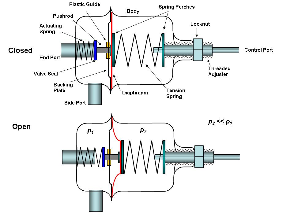
Posted by: pbanders Jan 26 2007, 06:08 PM
i'm wondering if this might help with the pesky idle fall off when the various electrical circuits are energized. were the lights on when you drove home? hi.
k
I'm working on that problem, too, and I think I'm getting closer to a solution. I think it's due to the poor nature of the alternator ground. I should have more on this in a couple of weeks. I don't think the decel valve will help this problem.
Posted by: John Jan 26 2007, 11:28 PM
I like the diagram, but I still don't see anything that would make this a check valve (one direction flow).
Have you been able to cut one open yet?
I'm guessing there is a poppet in there somewhere which would cut off flow in the wrong direction.
just my $0.02
Posted by: pbanders Jan 27 2007, 08:43 AM
I like the diagram, but I still don't see anything that would make this a check valve (one direction flow).
Have you been able to cut one open yet?
I'm guessing there is a poppet in there somewhere which would cut off flow in the wrong direction.
just my $0.02
The reason the valve is one way is that when manifold vacuum is applied to the side port, there's no pressure differential across the diaphragm because the same vacuum level is present in BOTH chambers, and the valve never opens.
Posted by: Bleyseng Jan 27 2007, 10:01 AM
My testing of a decel valve shows that it opens at 20-21hg pulled on the small end. At overrun the adding of fresh air into the manifold would lean out the AFR as the diaphram is already against the stopplate.
Posted by: pbanders Jan 27 2007, 12:19 PM
My testing of a decel valve shows that it opens at 20-21hg pulled on the small end. At overrun the adding of fresh air into the manifold would lean out the AFR as the diaphram is already against the stopplate.
Geoff, is that on the "unmolested" decel valve you have? The NOS decel valve I bought off of eBay (identical in construction to the 914's decel valve) is for a '77 Rabbit, and it's set to 15 inHg. I wouldn't be surprised if the 914's decel valve's setpoint is different.
Posted by: Bleyseng Jan 27 2007, 01:25 PM
Yeah, I am sending it to you along with the MPS's to look at.
Posted by: John Jan 27 2007, 06:44 PM
I'll buy that.
Posted by: orange914 Apr 2 2008, 05:55 PM
Why not put a direct link to the diagram in the "Info" section,
since posts about hose routing pop up every now and then.
--- bill
after searching info section i found this vaccuum diagram here. i second that it would find good use in the info. section

mike
Posted by: arvcube Apr 2 2008, 09:07 PM
OK, here's what I think the guts of this thing look like, open and closed - if you want to see the picture more clearly, click on it to open it in a separate window:
I think this diagram explains it all...Here's my take:
The Control Port is hooked up to the intake manifold (past the TB)
The End port is hooked up to the intake manifold (past the TB)
The Side port is hooked up to the air box or atmosphere.
P2 is completely sealed from P1
The End port is normally closed by some valve or plunger or whatever because of the spring pressure acted on it on the P2 side of the diaphragm.
When there is high manifold vacuum (overrun situation) the same amount of vacuum is applied to both the Control port and the End port (because they share the same source). Because the "valve" is sealing the End port (based on larger spring pressure), the End port is somewhat sealed or "plugged". Only when the manifold vacuum is high enough to overcome the spring pressure from the larger spring in the P2 area does the diaphragm deflect, thus opening the seal (valve, which is assisted by the smaller spring) from the End port, allowing fresh air to enter from side port to the manifold.
Extra air in the manifold during this overrun condition leans out the mixture and usually results in exhaust "popping." I think this would help to decrease exhaust emissions...
Posted by: McMark Apr 2 2008, 10:42 PM
It doesn't lean out the mixture as much as you're thinking because D-Jet is vacuum based. So this 'controlled air leak' will lower the vacuum from really-high-overrun-vacuum to somewhat-normal-idle-vacuum.
I wonder if disabling the deceleration valve would cause high overrun vacuum to hit the MPS and cause the MPS to fail prematurely... 
Posted by: Jeff Bowlsby Apr 2 2008, 11:40 PM
I wonder if disabling the deceleration valve would cause high overrun vacuum to hit the MPS and cause the MPS to fail prematurely...
Uh huh...yeppers.
The vacuum hose diagrams on my site including the decel valve are correct now.
http://members.rennlist.com/914_collectibles/RareDocs.htm
Posted by: arvcube Apr 2 2008, 11:42 PM
It doesn't lean out the mixture as much as you're thinking because D-Jet is vacuum based. So this 'controlled air leak' will lower the vacuum from really-high-overrun-vacuum to somewhat-normal-idle-vacuum.
I wonder if disabling the deceleration valve would cause high overrun vacuum to hit the MPS and cause the MPS to fail prematurely...
That makes sense...I think the functionality of the decel valve only applies to a limited range, dependent on how the spring pressure is set. So if the MPS measures manifold pressure, then high vacuum (idle or overrun situation, throttle closed) would cause the MPS to signal a leaner condition, while low to zero vacuum (WOT)would signal a richer condition...? if that's the case then maybe the decel valve was used as an additional way to lean out the exhaust emissions during these high vacuum situations even though the MPS and the "ecu" already does most of that....?

Posted by: roadster fan Apr 3 2008, 01:45 AM
And that, sir, is why you’re the king of D-Jet.
Thank you for all your efforts to expand the knowledge base of D-jet EFI. Without your research I would have never attempted to revive my 71 D-jet system.
The decel valve appears to be the perfect device to protect the MPS and would explain why early cars do not have one and later cars do.
should I add one to my early car? hmmm?Thanks again for making the complicated more understandable,
Jim
Powered by Invision Power Board (http://www.invisionboard.com)
© Invision Power Services (http://www.invisionpower.com)