Printable Version of Topic
Click here to view this topic in its original format
914World.com _ 914World Garage _ Center Console wiring
Posted by: malaga_red75 Apr 24 2007, 10:14 PM
Hey, so I just got my new to me center console....(Thanks Sean!!!!)
So, first thing i did was pull the gauges from the panel and test them. They all work!! clock still ticks, volt still works and the temp worked on accident as my dad and i touched the green wire to a power and the temp needle sweeped up.....anywyas.
I found some wires under the carpet, above the center tube, are these the wires for the gauges?? heres a picture. Thanks in advance!!
Attached image(s)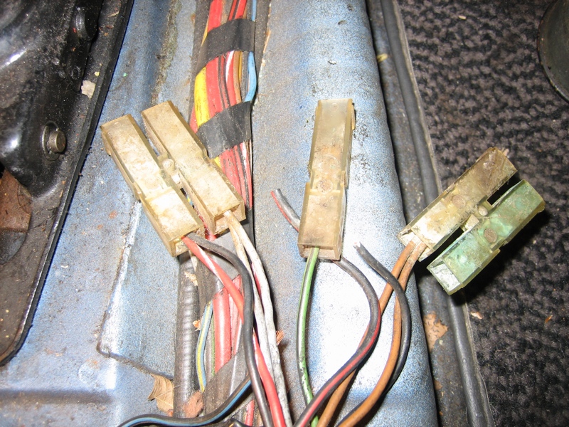
Posted by: malaga_red75 Apr 24 2007, 10:22 PM
also, can the gauge bezels be removed, i want to repaint them, and maybe replace the glass or plastic that covers the gauge.
-Peter
Posted by: Dave_Darling Apr 24 2007, 11:01 PM
Those are indeed the wires for the center console.
Brown == ground; always (unless some fool has been re-wiring things!)
Green/black == oil temp sender wire
Red/white (also black/red; both are crimped into the same connector) == switched power
Grey == instrument light power (black/blue wires in the console harness hook up to these!)
One of the two un-connected wires should be a black wire (constant power for the clock)
Looks like there's an extra black/blue wire and an extra black/red wire? Not sure what's going on with those.
The bezels can be removed, but it's fiddly to bend back the lip without messing everything up. You have to be careful, and if you screw up it can scratch and/or bend the bezel visibly.
--DD
Posted by: malaga_red75 Apr 24 2007, 11:12 PM

Green/black == oil temp sender wire
Thanks alot!
We had guessed that, and we were right. ON the green/black though, we connected it and the gauge didnt change after a couple of minutes of the engine running, and we knew we had power. Could the wire be disconnected in the engine bay? If so, where does it connect??
Thanks!
-Peter
Posted by: Dave_Darling Apr 25 2007, 12:25 AM
Under the battery somewhere should be a single-wire plastic box connector, similar to the ones in your picture above. The wire connects there to another green/black wire that runs across the front of the engine under the engine tin, and winds up going into the "taco plate" at the left-front corner of the bottom of the motor.
--DD
Posted by: 914Sixer Apr 25 2007, 08:30 AM
Black/blue is for defroster light on console and the brown ground. Black/red to the floor defroster lever I think.
Posted by: iamchappy Apr 25 2007, 08:50 AM

Attached thumbnail(s)
Posted by: Carlitos Way Apr 25 2007, 01:03 PM
This looks like a classic thread to me.
Posted by: malaga_red75 Apr 25 2007, 02:44 PM
This looks like a classic thread to me.
I'd be honored to have a classic thread started by me!!!
And that wiring diagram is the best thing I have ever seen!!!!
-Peter
ps, i was able to get one of the bezels off, so i think i might start a thread of reviving my center console gauges....and maybe painting the bezels the same color as my car....any thoughts on that??
Posted by: malaga_red75 Apr 25 2007, 11:24 PM
hey,
I found the wire under the battery and it wasn't connected to anything....i searched for the wire, but I couldn't find it.
-Is it possible for my car not to have a temp?? (1975 1.8 L-jet)
-Does anyone have a picture of where the wire goes into the engine? DD's explanation was good but I am stil not quite sure where exactly it goes.
Thanks!
-Peter
Posted by: Cap'n Krusty Apr 26 2007, 12:30 AM
Left front corner of the bottom of the engine case, mounted in the cover there. You probably don't have one. Needs to be the correct sender for the gauge, and the mounting plates (2 pieces w/a gasket in between) are pretty available used. New, the set is about $125 without the sender. The Cap'n
Posted by: drewvw Apr 26 2007, 01:43 PM
the wiring diagram for the center console is in the Chilton's 914 manual. That's how I wired mine.
If you can't get ahold of that I could try to scan it but its basically the same as the "yellow paper" version (nice job).
Powered by Invision Power Board (http://www.invisionboard.com)
© Invision Power Services (http://www.invisionpower.com)