Printable Version of Topic
Click here to view this topic in its original format
914World.com _ 914World Garage _ Bringing out the dead
Posted by: Jeff Hail Oct 1 2007, 11:35 PM
Bringing Out The Dead.....or how to restore a rusty 914 and convert it to a street/track car when I have time after dealing with everyone elses stuff.
My background is collision and restoration (day job) of high end automobiles for 28 years in addition to race fabrication. I jumped the fence and left that industry to pursue pretty much the same thing except on the paperwork end which is really boring and thankless. (another day job)
I look at rust like a diamond in the rough. Rust is afraid of me because it know's it cannot live in my world. Metal becomes submissive because I have confidence in my metal working talents. I will add to this post as work progress's.
I hope my years of experience can help others as I add. I believe there is a right way to repair a car and wrong way. I metal finish because in the end its cleaner, lighter and stronger. I was taught old school techniques with new school technology. A great combination. I also believe in doing a job once correctly using the highest quality materials and proper tools. Many ways to skin a cat I say. If you hold it by the tail it can still bite!
Good advice to follow:
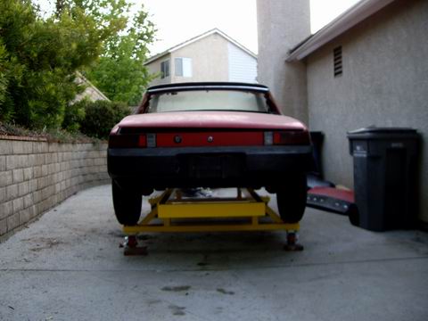
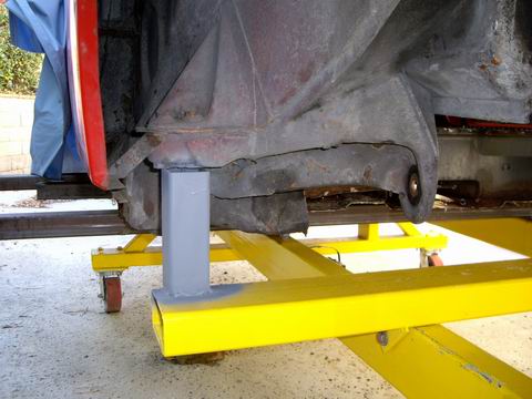
Take measurements of the door openings and targa bar to windshield header. Cross measure then do it again to confirm. Recheck your measurements against the factory figures. Make a couple of adjustable braces for each side that attach from the upper seat belt anchors to the door hinges. I recommend cross braces also right to left. These can be made from rod or tube and turnbuckles for cheap. Racer Chris has some really nice ones with rod ends. Support the car from below equally on both sides of the undercarriage and front and rear. I do not believe jack stands can hold the proper tolerances at 4 points. It takes a minimum of 6 and preferably 8. These are all easy to do and are essential to a square and level chassis. Not everyone can afford a Cellete bench or hourly frame time at a shop for these type of do it yourself repairs. Impovisation can be done correctly and for a lot less money. Make sure your floor or platform is level.
Keep in mind that tolerances for the 914 were 7-9mm from the factory so anything you can do to make it better is worth it. 7mm by today’s standards is huge. 9mm is a Grand Canyon. Anything you can do to tighten the tolerances will provide a better end product. Exterior panels were fit with the adjust and weld method and are only a skin.
My 914 had measurements all over the place on the front end and the rust issues were all in the rear that needed correction. Car was never in any collisions.
90% of the measurements were factory assembly tolerances. Porsche's aint perfect.
I made my own dedicated bench for 911's and 914's. By some stroke of luck I ended up with a 1 mm variance in height (datum) and 2mm in length and width is zero with my own fixtures. This has been substantiated with endless anal cross measuring and factory manuals. I used a steel front suspension cross member as a front body holding fixture. I went through 4 before I found an acceptable one. The first 3 were so far off factory tolerances (4-6 mm out of square) I rejected them before I found a good one.
My bench is not for pulling. It was designed for assembly and replacement of structural parts. It will support 3,000 pounds. $350 worth of steel and another $175 in industrial castors was worth it considering its use. A stripped 914 shell is a feather and easy to roll around. When you cut and replace structural parts recheck your measurements. Control points change when you remove, replace and weld in new parts. They are easily controlled with patience.
If it does not come out perfect do not lose sleep. Remember tolerance and variance was not perfect from the factory. If you have a control point locating hole that is 14 mm a dowel or pin of 9-10mm was used during birth. That is why suspension systems are adjustable for variance and wear. You will also find center indexing points on the front and rear of the body. Easy tools to use are plumb lines, tape measures and levels if you do not have access to high end measuring equipment. You can locate and make symmetrical measurements throughout repairs. If you have one side that is undamaged or not rusted use that side as a starting point for measurements. Use panel gaps as a visual indicator during repairs and welding.
3 important factors- height, length and width. If you are me then there are 4 (Z axis) and that one will make you lose sleep!
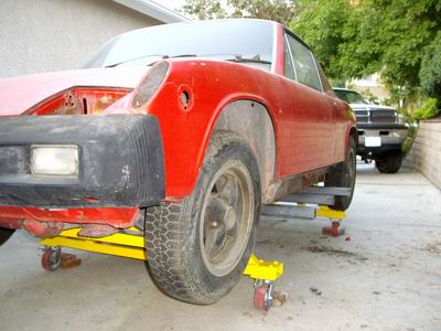
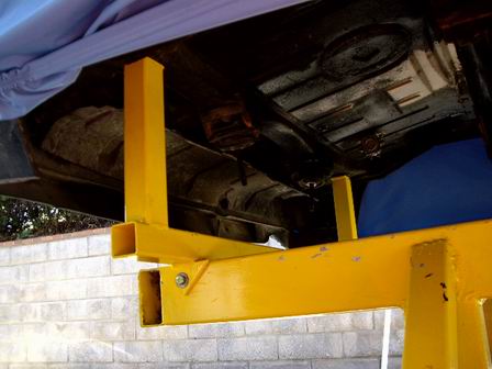
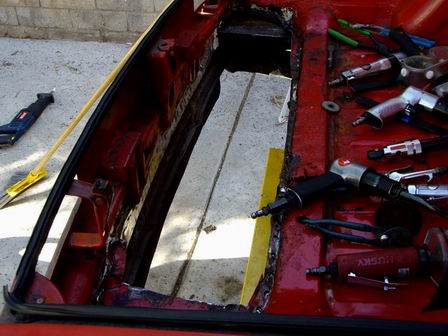
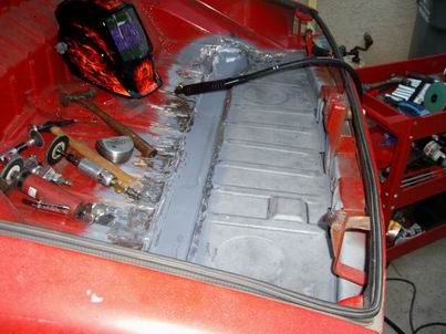
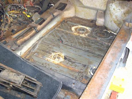
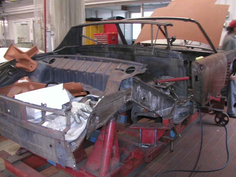
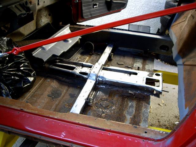
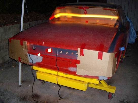
Some pics of the beggining: A back east 914 comes to California.
Attached image(s)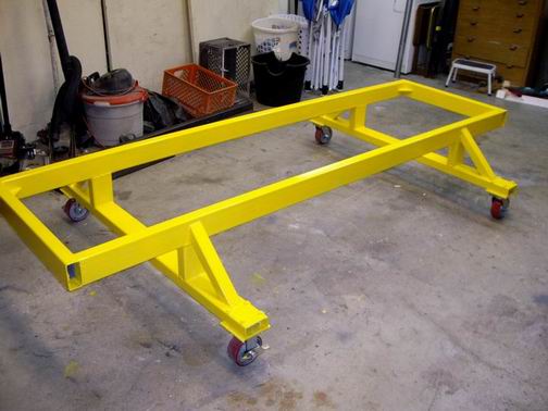
Posted by: Jeff Hail Oct 1 2007, 11:37 PM
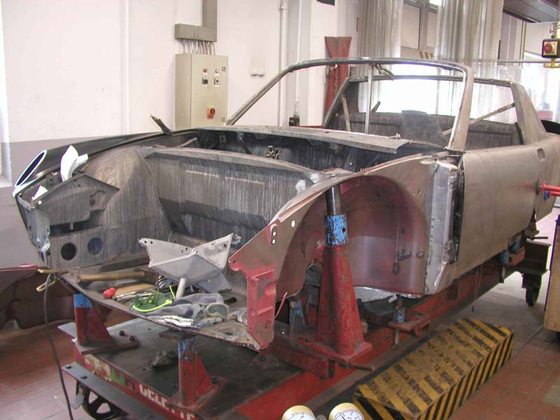
Contd
Attached image(s)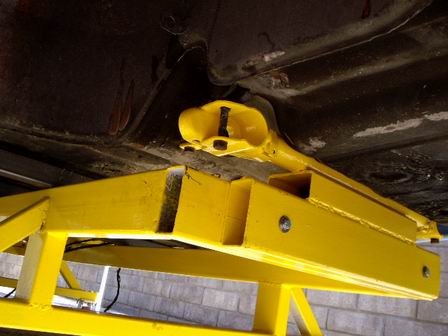
Posted by: Jeff Hail Oct 1 2007, 11:41 PM

Contd
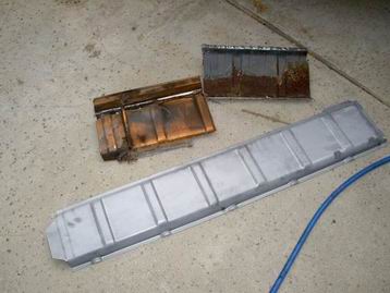
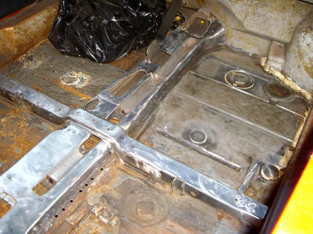
Rear floor replacement. An yes the RD floors will work in a 1975 914. A little metal work in the rear corners will lay right down flat on the bumper absorber reinforcements allowing full panel replacment without clipping the rear pockets.
Attached image(s)
Posted by: Eric_Shea Oct 1 2007, 11:43 PM
Wow 

This'll be a fun one to watch.
Posted by: Jeff Hail Oct 1 2007, 11:47 PM
Wow
This'll be a fun one to watch.
And Eric I will be calling you.
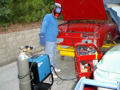
Floor contd.
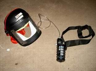
Damn cool welding helmet if you ask me!
Attached image(s)
Posted by: jd74914 Oct 1 2007, 11:52 PM
Nice work, I can't wait to see more . . . and
:welcome:
Posted by: Jeff Hail Oct 1 2007, 11:57 PM
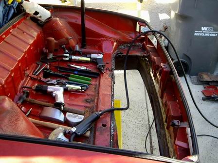
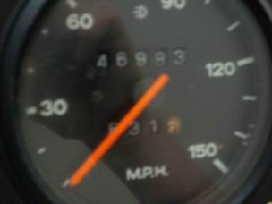
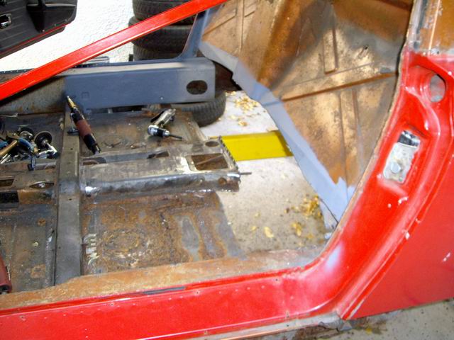
Interior stripped.
Odometer? DMV say its for real and so do the prior owners receipts. (least of my concerns) Its about the fun!
Attached image(s)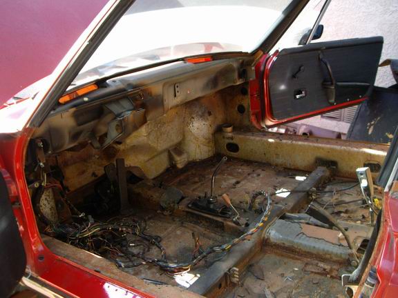
Posted by: Jeff Hail Oct 2 2007, 12:08 AM
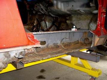
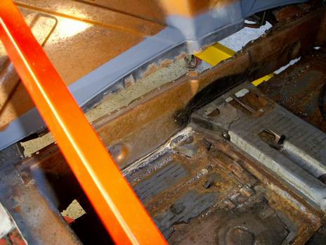
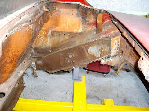
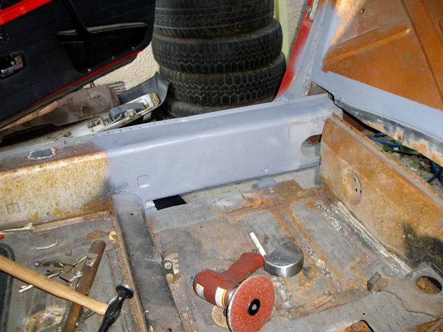
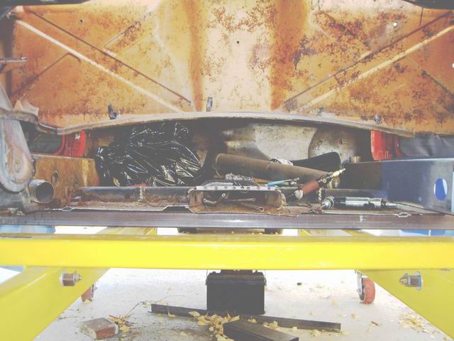
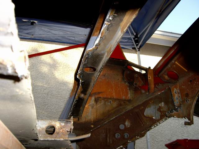
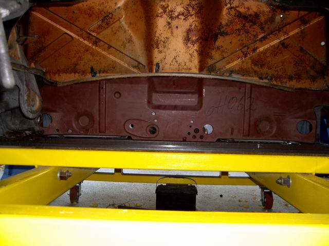
Moving along into the rocker and longs. This was how car was received.
The good. Right upper wheelhouse is sound and so is the outer suspension perch.
Left rocker/ outer long. Pretty normal for an east coaster.
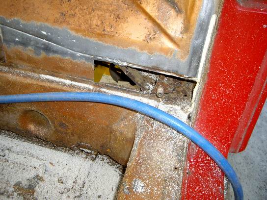
Right side is another story. Ugly. Outer is shot. Corner of the floor is gone.
Inner long lower gone. Inner console has been seem welded prior due to rust and it is going to metal heaven.
Attached image(s)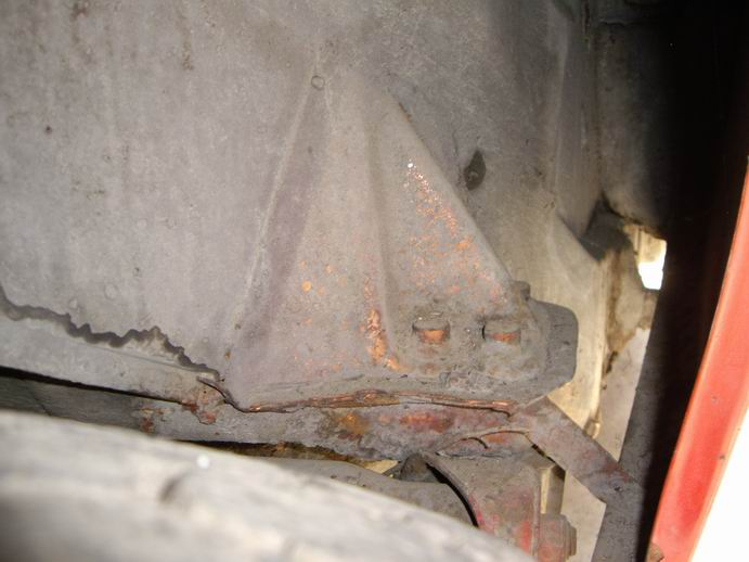
Posted by: Jeff Hail Oct 2 2007, 12:17 AM
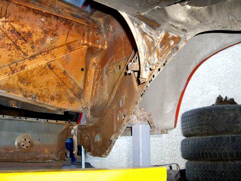
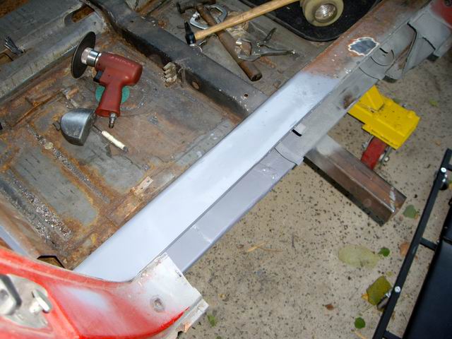
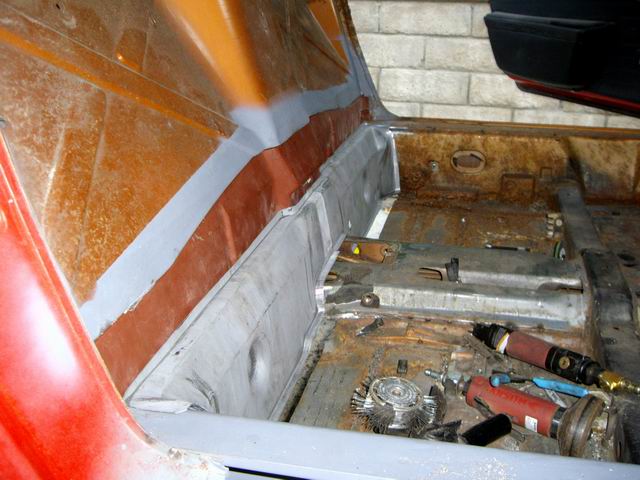
Cut out the rusted outer. Actually only the rear 1/4 was bad. Since I have a replacement and need access to the inner long whole piece is getting replaced
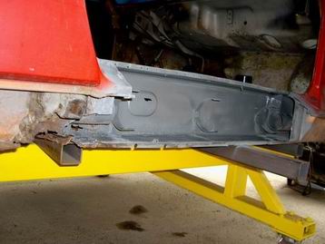
Media blasted the inner long and only the area around 4 inches in front of the jackpost/ seatbelt anchor is bad. I will fabricate, section and sleeve that in back to behind the firewall. I have a new outer wheelhouse which provides half the box on the outside which will make that area and rearward easier to repair.
Attached image(s)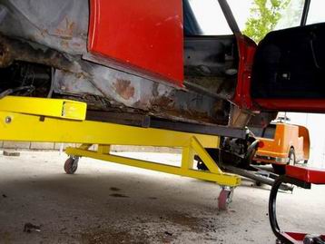
Posted by: KELTY360 Oct 2 2007, 12:42 AM
Are you the Jeff Hail of the Mulholland thread on Pelican? I've read the whole thing and follow it constantly. Best thread ever.
Nice work on your teener.
Posted by: Twystd1 Oct 2 2007, 12:48 AM
Were you part of the Mulholland crew back in the day?
Clayton
Posted by: Jeff Hail Oct 2 2007, 12:54 AM
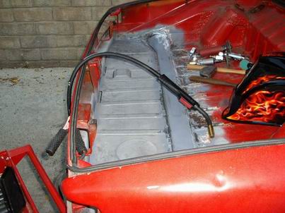
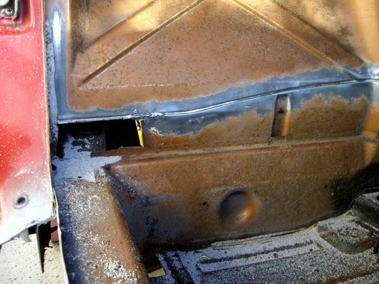
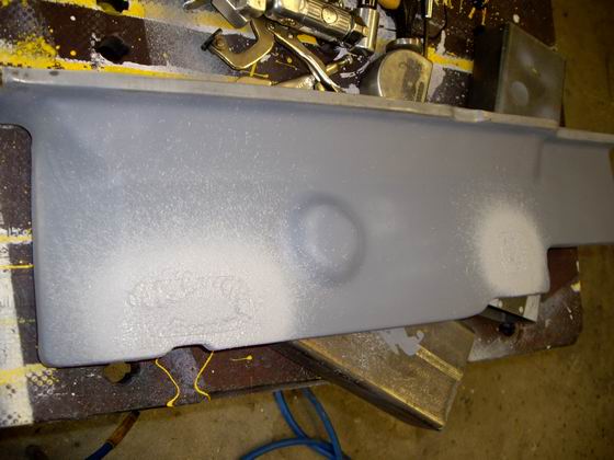
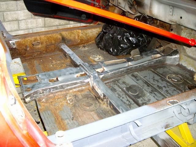
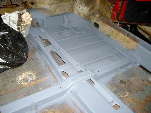
Floor metal finished and primed. No filler.
I did end up installing the entire floor as it comes from Bill at RD.
The old floor had some minor rust at the weld tracks near the rear of the structural crossmember underneath. That 4 extra inches of sheetmetal is easier to lap weld in then butt weld to dirty steel. It makes my finish work less time consuming also. I treated the inside of the crossmember and sealed that up prior to welding in the new panel. The entire trunk will be media stripped. I just threw some primer on for now until this weekend.
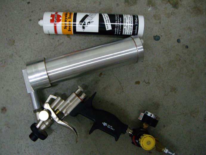
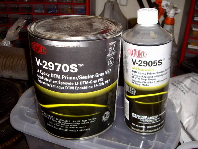
I will hit it will some Starblast media (DuPont), epoxy prime and then seal all the seams with Wurth Sprayable Seam Sealer for that oem look and texture.
Attached image(s)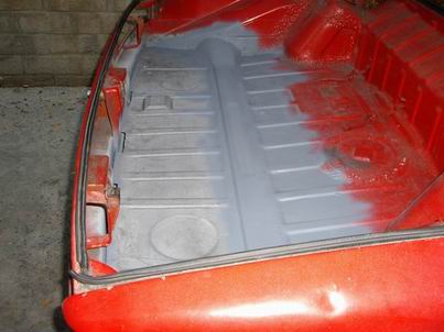
Posted by: Jeff Hail Oct 2 2007, 01:00 AM
Are you the Jeff Hail of the Mulholland thread on Pelican? I've read the whole thing and follow it constantly. Best thread ever.
Nice work on your teener.
Yours truly one and the same....
Posted by: Jeff Hail Oct 2 2007, 01:19 AM
Were you part of the Mulholland crew back in the day?
Clayton
Yes- One of many groups over the years.
Posted by: Lou W Oct 2 2007, 03:07 AM
Keep the pctures coming. 
Posted by: Justin Fischer Oct 2 2007, 08:18 AM
Wow, that was some introduction. Keep the pics coming, great project!!
Posted by: SGB Oct 2 2007, 08:27 AM
shhhh.
Artist at work.
Thats really impressive.
Posted by: pin31 Oct 2 2007, 10:11 AM
Very cool !!!
Someone should write a book.

Posted by: Jeff Hail Oct 6 2007, 09:22 PM
This weeks installment of Bringing out the dead
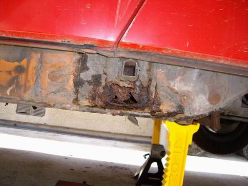
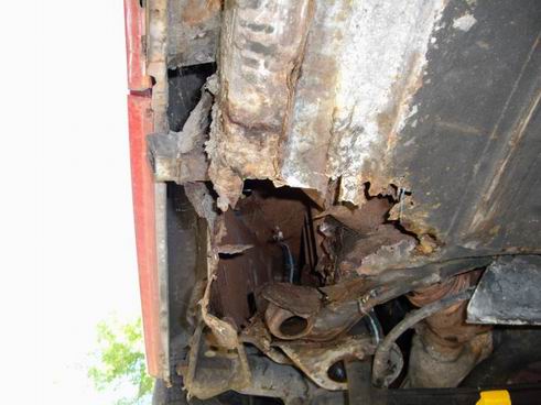
Attacking the firewall.
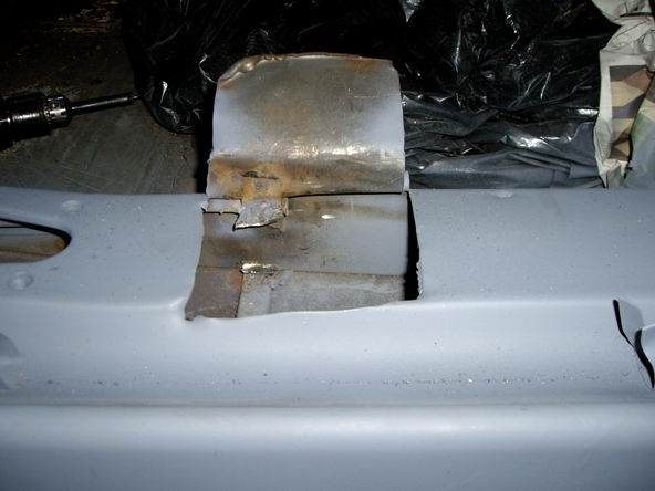
This car had rust at the bottom of the lower firewall. Prior repairs included welding in plumbers tape with what looks like an arc welder of all things. Seems the floor rusted along with the firewall at the bottom seem and it was held together with "L" shaped pumbers tape or and angle iron/ shelf bracket.
I assessed the firewall at the long junction which is also prone to rust from leaks at the window and hell pit. Cut the corners out to access the inner longs which require some work anyways.
It's only metal.....
Attached image(s)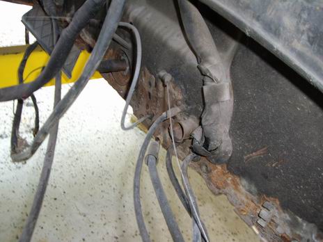
Posted by: Jeff Hail Oct 6 2007, 09:32 PM
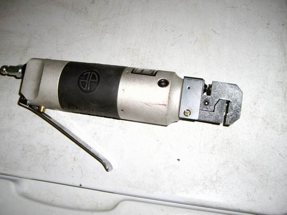
Some great tools to have are the Astro Scraper. Its like a minature air chisel except has super high speed short strokes and does not damage the surface underneath. Comes with an assortment of blades and scrapers included. They run $40. I stripped the entire floor tar pads in about 7 minutes flat.
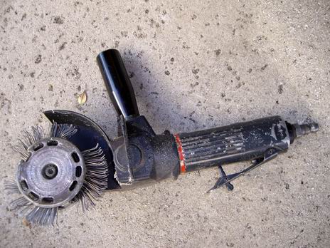
The other tool I have and is worth it weight in gold is the Wurth Master. It is pretty much a flail with the needle brush mounted. Different wheels are for stripe and double sided tape removal but the flail wheel removes the factory seam sealer with zero effort. Everyone knows the oem seam sealers can be like concrete.
These are expensive so it pays if you know someone who has one for limited use versus purchasing one.
Attached image(s)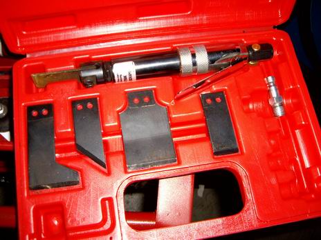
Posted by: sixnotfour Oct 6 2007, 09:36 PM
I am in shock that some one in CA would take on this project.
We have seen countless Less rusty cars been cut up down there. (CA.)
My Hat is off to you, Great Job.
Posted by: Jeff Hail Oct 6 2007, 09:50 PM
Seam sealer stripped off the inner firewall with the Wurth Master. Leaves a clean bare metal surface.
I will say removing the wiring harness is a pain in the ass. I have come to the conclusion that the factory fed it through the tunnel and out the rear firewall without the sheath with the two big grommets that plug the firewall and front shelf. I think they installed that sheath from the back end after the loom was routed. Just my opinion.
I am actually thinking about modular-izing the loom. Wouldnt take much to do it. I have to unwrap it anyhow because I has some areas that need repair and shrink tube. I also cut a little insulation here and there doing the removal.
Must be wondering why I removed the the seam sealer on the inside of the firewall???
Thanks to Perry I have a NOS lower firewall and it will get replaced.
This is actually an early firewall but will adapt to the 75' easily with little modification. I will reinforce the e-brake and clutch and cable junctions on the inside of the panel prior to the installation. I will make it stronger than the factory did and it will all be hidden. This area is one of the 914's design flaws.
Part of my project is improving on some of the factory shortcomings. Making improvements invisible or at least less visible is the challenge.
Stay tuned!
Attached image(s)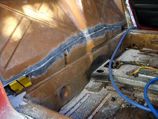
Posted by: Jeff Hail Oct 6 2007, 11:00 PM
I am in shock that some one in CA would take on this project.
We have seen countless Less rusty cars been cut up down there. (CA.)
My Hat is off to you, Great Job.
Thanks, back at ya!
I have looked at countless 914 tubs. Very few are truly rust free. This tub cost me nothing. It has never been in a collision and the upper body is straight. It has rust issues that are all easily corrected. It is really not as bad as it looks. Time consuming yes but easily corrected. In the end I will know every square inch of this car is sound and "clean". I have seen too many so called rust free tubs that have surprises in them. I could have spent top dollar on someone else's car not knowing what went into it. Then tearing it down and starting from scratch. This car has some issues but what 914 doesnt?
Taking a step back I could have found a perfect car. Considering the modifications planned I would still have to perform sheetmetal work. This is all part of the game plan. Just a few extra steps to take. Of course it also saves another 914! (sort of)
This project isn't about time or cost. In fact I do not have that much into it. It is about the goal. I am not restoring a 914. I am building a Porsche the way the factory intended but Volkswagon got in the way. A few special "options" thrown in that were not available will be added.
The basic build plan:
Mid Engine Configuration
Short wheelbase
Under 2000 lbs
Low CG
250+ HP flat six
A car that can be street driven and tracked
A whole heap of aftermarket performance vendors at my disposal.....
A build that generates "smiles per hour"........and spanks the unsuspecting.
I considered just buying a car. The mid engine ones I want are out of my price range with the Prancing Horse emblems. I considered buying an Elise that fit my build plan but I think I can do better for less. Besides I hate English cars.
Throttle on!
Posted by: Jeff Hail Oct 7 2007, 12:06 AM
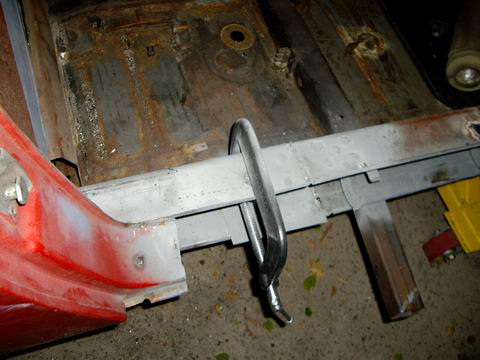
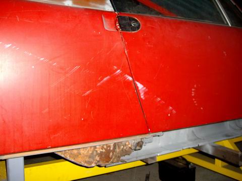
You gotta have bars. Keep those gaps in check when performing any major work on the longs or floor. Even with the body fully supported from below the roof/ hinge pillars need to be kept under flex control at all times when replacing sheetmetal.
I made these to work with the doors on the car. You cannot check the door gaps while in progress without doors mounted. It makes the job easier and I know what the end product will be. Heat during welding makes metal expand and contract. Anyone who has ever replaced a rocker panel on any car (even with a full roof) knows how important this is.
If a 914 left the factory out of spec (yes they have) this is where it can be corrected. The door bars can be adjusted to put the windshield header and roll bar in perfect spec.
If it starts straight it will end up straight!
Attached image(s)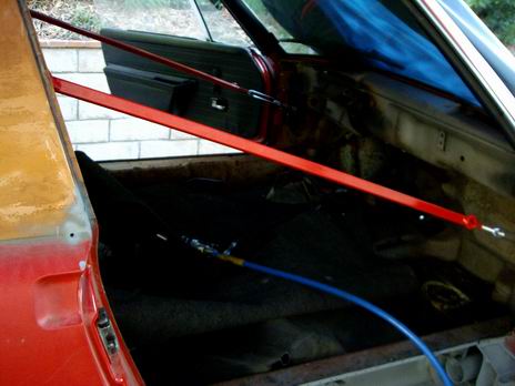
Posted by: Jeff Hail Oct 7 2007, 12:13 AM
This is an original Coppertone car that was re-painted red later in its life. Its a little hard to tell rust from paint in photos.
Posted by: stateofidleness Oct 7 2007, 01:11 AM
even if you're just cutting out small patches from the pans? (say 3" by 3" tops) and no work being done on the longs
*subscribes* really interested to see the progress on the firewall repair! i have those exact holes and curious to see the fix.
question. did you remove the wiring harness? it is a pain... i sleeved mine for the time being but didnt know if it needed to be removed if i was going to be welding around it
and im also assuming you dropped the engine? for the battery tray area?
Posted by: Jeff Hail Oct 7 2007, 01:41 AM
even if you're just cutting out small patches from the pans? (say 3" by 3" tops) and no work being done on the longs
*subscribes* really interested to see the progress on the firewall repair! i have those exact holes and curious to see the fix.
question. did you remove the wiring harness? it is a pain... i sleeved mine for the time being but didnt know if it needed to be removed if i was going to be welding around it
and im also assuming you dropped the engine? for the battery tray area?
If you are quilting patches in or just repairing the floors I would not go to such an extreme as I have with a fixture and door supports. I have stripped my tub to just a shell. I have left only the glass in so little critter's do not find a place to camp out for the winter. I hate when four legged things jump out of nowhere at me.
Yes I have removed the wiring harness. If you are doing spot repairs leave the harness in or only partially remove/ pullback for any welding in the firewall/ tunnel area repairs.. I have to repair some areas of the loom anyway and I find it it my way if left in the car. Engine is out and being replaced with a six. The four cylinder mounts will disappear on the inner longs.
Posted by: watsonrx13 Oct 7 2007, 07:30 AM
Very nice photo-documentary on the restoration of this vechile...
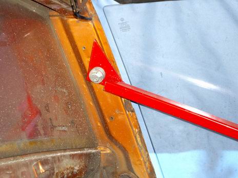
Can you show a better photo of where the bars are attached and describe how the bar is constructed?
-- Rob
Posted by: KELTY360 Oct 7 2007, 10:07 AM
That lower firewall is serious sheetmetal porn. 
You da man Jeff! 
Posted by: Jeff Hail Oct 7 2007, 02:52 PM
Very nice photo-documentary on the restoration of this vechile...
Can you show a better photo of where the bars are attached and describe how the bar is constructed?
-- Rob
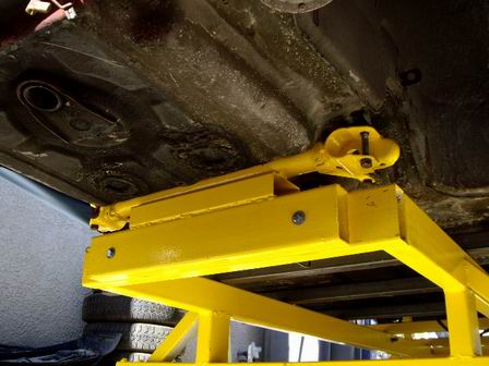
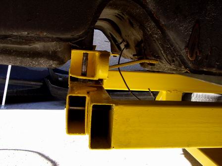
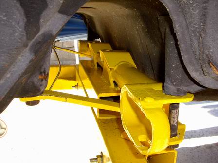
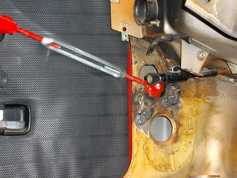
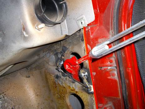
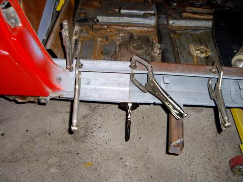
The bars were constructed of 1x1 square tube 1/8 wall. I welded some turnbuckles in and attached some scrap plate on each end. The anchoring points are the upper seatbelt bolt and in front just inboard of the upper hinge on the inner hinge post below the cowl. If the car was not fully supported from below then the upper hinge would be the best location with the doors off. When I took measurements with the car fully assembled the passenger side was in spec which surprised me. The driver side was wide by another 1/8 inch.
On another note the front floors are in good shape forward of the seat crossmember.. Typical flash rust at the tunnel flanges only. Will clean up easily.
I am replacing the floor behind the crossmember because its gone at the firewall.
Attached image(s)
Posted by: Jeff Hail Oct 7 2007, 07:49 PM
The lower outer firewall is out. I didn't even damage the airtubes removing the old panel. Had to cut the control tubes which will be rebuilt and modified anyway.
The lower inner firewall will need a section lapped and flanged to fit the floor. It's all flat metal- piece of cake.
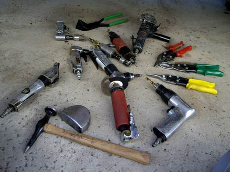
Tools of the trade.
Ok....the hard work is done (hehe) Its fabrication time.
Some observations. About 1 out of every 10 resistance weld's from the factory had poor or no penetration. Also the flange that connects the lower outer firewall to the longs (between the air tube and inner long) had no welds. It was filled up with seam sealer. I'd swear this tub was assembled at the factory on a Thursday.
Some flash rust here and there but nothing too bad. A Roloc disc will remove most.
Maybe Racer Chris could donate one of his "Raised Pickup Point Kits" for this build....?
Attached image(s)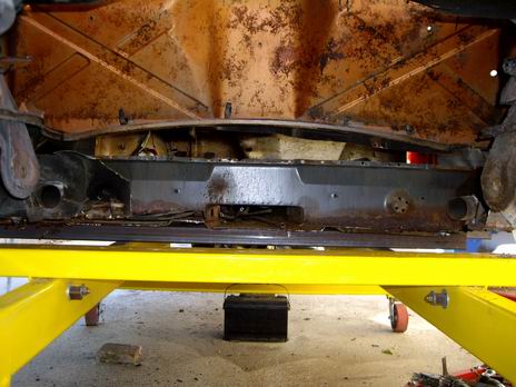
Posted by: Jeff Hail Oct 14 2007, 09:08 PM
Didn't get much done with the car this week. Busy at work during the week and ended up in bed with the flu Friday night and Saturday. Feel much better except except cannot invert my head to weld due to my sinus's are loaded up. Since I am glutton for punishment and hate being stuck indoors I did some cutting and trimming today. Just felt good to get out and do something.
I added some fixtures for the outer suspension control points. Since I am getting into the rails I need to support this area.
Cut out the old right suspension console and rail (inner long) I truly have a rust free 914 now. Interesting enought these were welded from the factory with stainless wire if not TIG'd. Ate up the cut off disc's really fast.
You guys must be thinking I am nuts? No just on a mission.
Attached image(s)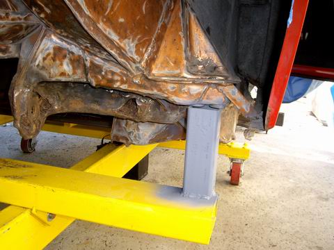
Posted by: Jeff Hail Oct 14 2007, 09:18 PM
I could have repaired and sectioned the right inner rail. Would have been a lot of work considering how rusted the lower and inner were so I decided to order the rail from AA. The corrugations would have been challenging to reproduce and would have required a lot of cuts and scab metal. Since the 4 cyl mounts are going by-by and the rail will be exposed I said what the "F"? You only live once. The AA part is going to require some fitting. It is rough but the quality is good. I will still reproduce the double wall as the factory did.
The body did not move at all when the rail was cut out. The 914 chassis is still pretty stiff in design when it is just a shell.
Attached image(s)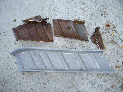
Posted by: Jeff Hail Oct 14 2007, 09:35 PM
The outer wheelhouse metal is sound. I was surpised that no rust was found at the lower rail area other than flash rust inside the box area. Still solid.
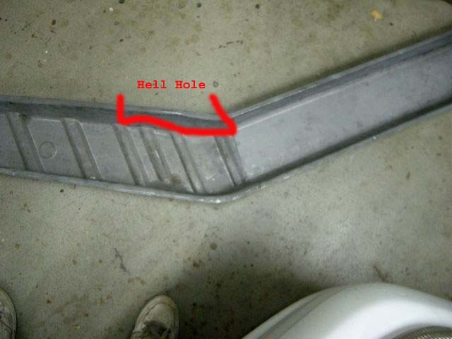
One observation was apparent. The rust issue on 914's is not just from battery acid. The area's below the hellhole are prone to rust because they are also high flex area's. The area's like the hell hole and just behind the seats at the firewall go from very stiffly reinforced structure to single layer metal. This is a flexible area and the paint/ coatings tend to not flex over the cars life and lift exposing the metal to acid, water etc. I have seen many 914's that are sealed better than others. I to this day cannot figure out why they didn't angle the hellhole shelf to drain better than make it flat like a holding pond?
Attached image(s)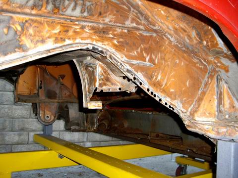
Posted by: type11969 Oct 14 2007, 09:50 PM
Jeff- nice work, just figured out that you were the same jeff that posted in my thread! Those underbody jigs are nice . . . wish I had them. I may have to pick your brain at some point to figure out a way to line up the front suspension points on my 914. It was in an accident and the drivers quarter (and then some) was replaced right up to the suspension mounting point. It has to have been knocked out of alignment, if not by the accident, then certainly by the (poor) welding.
Keep up the good work!
-Chris
Posted by: Jeff Hail Oct 14 2007, 11:11 PM
Jeff- nice work, just figured out that you were the same jeff that posted in my thread! Those underbody jigs are nice . . . wish I had them. I may have to pick your brain at some point to figure out a way to line up the front suspension points on my 914. It was in an accident and the drivers quarter (and then some) was replaced right up to the suspension mounting point. It has to have been knocked out of alignment, if not by the accident, then certainly by the (poor) welding.
Keep up the good work!
-Chris
Chris,
My 914 has had the right rear suspension console repaired in it's life. It has gobs of welding on the right side. It looked as if it had one of Racer Chris's ear reinforcements installed. It was never treated for corrosion so it rusted out badly. A big 3 inch washer had been welded in to gain some life on the inner ear. It was pretty bad. A dust pan full of rust came out when I cut the console off. It's getting lighter by the day!
Before any cutting I took some measurements. All 914's seems to have some variance at the suspension mounting area's in as much as 1/2 inch measured center to each side. I measured from the center hole at the upper firewall just above the lower firewall seam to the inner console bolt hole. Considering how much rot the right rear console had no sag was found and was equal side to side. The measurement was 28-1/4 from the firewall hole to the front edge of the console bolt hole. I prefer center to center hole measurements but the right console was so far gone I couldnt rely on it. Side to side from inner console to inner console was 33-1/2 from outside to outside on the bolt hole.
I have some measurements from 914World, Pelican and an old Mitchell book. I have still been trying to locate datum (height) measurements to no avail. A this point I am not worried as my car still has consistency side to side. The jigs are a plus as it provides support and a reference point for location with no flex. The body is so light stripped nothing moves.
My front suspension control points were not perfect from the factory. The forward bracket on the body that locate's the front suspension crossmember was about an 1/8 to far back on the right side. The bracket on the suspension crossmember has slotted holes that go to the rear mount so it still fits without binding. A lot of caster and camber adjustment is available on the strut tower it probably doesnt make much difference but I decided to remove and reweld the bracket where it should have been for proper Steering Axis Inclination. My car has not had any structural damage from collision which is a plus but the rust work is plenty to keep me busy.
Posted by: tdgray Oct 15 2007, 07:56 AM
Great work Jeff.... great when you get to say... "hey I did it myself"
Posted by: type11969 Oct 15 2007, 08:11 AM
Jeff-
Thanks for the info. I've tried using the pics on this site before but they are so blurry that it is sometimes tough to figure out what is what. I have plenty to contend with in the rear first before I start worrying about the front again though . . .
-Chris
Jeff- nice work, just figured out that you were the same jeff that posted in my thread! Those underbody jigs are nice . . . wish I had them. I may have to pick your brain at some point to figure out a way to line up the front suspension points on my 914. It was in an accident and the drivers quarter (and then some) was replaced right up to the suspension mounting point. It has to have been knocked out of alignment, if not by the accident, then certainly by the (poor) welding.
Keep up the good work!
-Chris
Chris,
My 914 has had the right rear suspension console repaired in it's life. It has gobs of welding on the right side. It looked as if it had one of Racer Chris's ear reinforcements installed. It was never treated for corrosion so it rusted out badly. A big 3 inch washer had been welded in to gain some life on the inner ear. It was pretty bad. A dust pan full of rust came out when I cut the console off. It's getting lighter by the day!
Before any cutting I took some measurements. All 914's seems to have some variance at the suspension mounting area's in as much as 1/2 inch measured center to each side. I measured from the center hole at the upper firewall just above the lower firewall seam to the inner console bolt hole. Considering how much rot the right rear console had no sag was found and was equal side to side. The measurement was 28-1/4 from the firewall hole to the front edge of the console bolt hole. I prefer center to center hole measurements but the right console was so far gone I couldnt rely on it. Side to side from inner console to inner console was 33-1/2 from outside to outside on the bolt hole.
I have some measurements from 914World, Pelican and an old Mitchell book. I have still been trying to locate datum (height) measurements to no avail. A this point I am not worried as my car still has consistency side to side. The jigs are a plus as it provides support and a reference point for location with no flex. The body is so light stripped nothing moves.
My front suspension control points were not perfect from the factory. The forward bracket on the body that locate's the front suspension crossmember was about an 1/8 to far back on the right side. The bracket on the suspension crossmember has slotted holes that go to the rear mount so it still fits without binding. A lot of caster and camber adjustment is available on the strut tower it probably doesnt make much difference but I decided to remove and reweld the bracket where it should have been for proper Steering Axis Inclination. My car has not had any structural damage from collision which is a plus but the rust work is plenty to keep me busy.
Posted by: Jeff Hail Oct 16 2007, 09:19 PM
A couple of hours to play today.
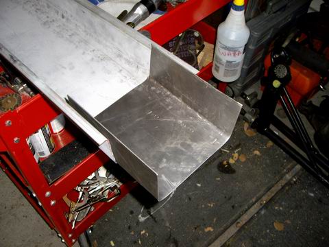
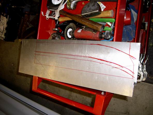
Cut the old inner long to prepare for the replacement section at the rear. Measure correctly because you only get one chance. If you cut long you get two chances. If you cut it too short consider eating out.
Perfect cut!
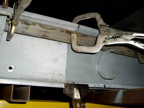
Here are some mock up's of the new panel being held in with Visegrips. Just double checking the fit and then I ran out of daylight.
I use a piece of angle bar stock or anything flat and stiff to backup the old and new panel. This way I know both are level during fitting. When I go to weld I will place bars on all 3 sides of the panel to make sure it is square.
Attached image(s)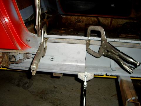
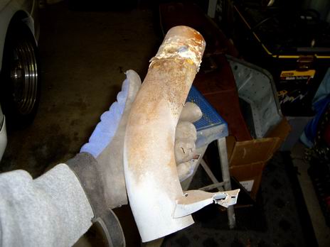
Posted by: Jeff Hail Oct 16 2007, 09:30 PM
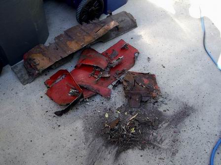
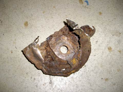
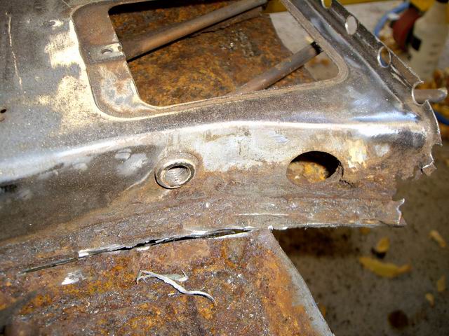
Rust is a crafty beast. If you can see rust you are only seeing the surface. My rule of thumb has always been you only see 10-20% on the outside. 914's rust from the inside and this is a perfect example. This is the old rear inner long that was cut out. The airtube area is rusted and was destroyed during removal.
From the outside all you see is the perforation down by the floor. On the inside its history. Unless you remove the outer longs you will never know how bad it really is inside. I guess this area can be referred to as south of hell. It's only metal!!!!!!!!!!
Attached image(s)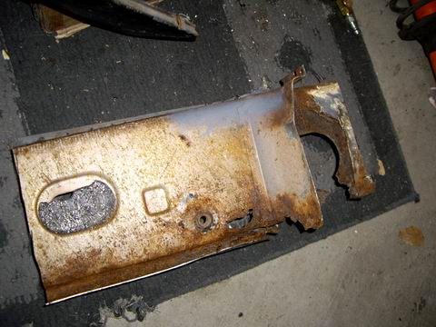

Posted by: Jeff Hail Oct 16 2007, 09:48 PM
I mentioned the other day double walled panels. This is one of them. I traced the second layer with a Sharpie to show where it starts and stops. This is where the lower wheelhouse comes together with the inner long. It is a entirely separate plate from the long and wheelhouse. You will also notice it has a radius to it. The radius is to allow some flex in the panel without making it to rigid.
If panel connections are in a high flex zone they need to be able to move by design. If they do not flex you end up with metal fatigue. A secondary purpose is to reinforce the seatbelt anchor area from pulling out in a collision. Imagine a 200lb man going from 65mph to 0 in 10ths of a second. That is a lot of energy focused on a tiny bolt anchor in a very short time. Cheap insurance. In the back of my mind I think Karmann knew this area was prone to corrosion so they added a little more metal down to the anchor mount.
Manufacturers use double walls for a reason. Stressed area's, panel intersections and joints. I will fab the extra layer and add it in later. Notice the seatbelt anchor is located in this strengthened area and it is ready to fall out now from the rust damage.
The rear corner of the inner long connects to the inner lower firewall. This area makes up a portion of what is called a torque box. It is one of the strongest area's of the vehicle. It is in this lower area from side to side when all panels are tied together to the center tunnel it forms a structure. Do not compromise here. Do not take shortcuts.
Attached image(s)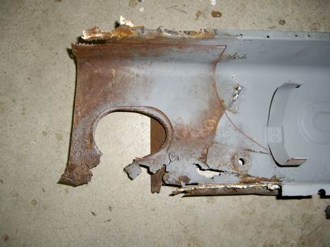
Posted by: Jeff Hail Oct 16 2007, 10:01 PM
A mock up shot from underneath.
Attached image(s)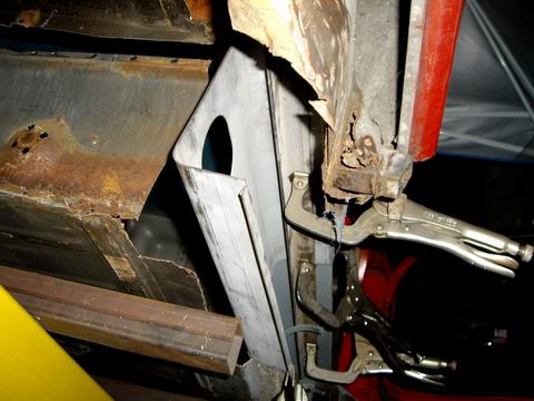
Posted by: Jeff Hail Oct 16 2007, 10:35 PM
An important note I would like to mention: "Inserts and sleeves"The focus here is on the 914 but apply's to any car. More so one without a fixed roof!
Whenever you make a butt welded joint whether on a rocker panel, A-pillar, center post or quarter panel/ sail panel and hinge pillars you have to make a sleeve or an insert and it needs to be properly sized and welded. This would not apply to butt welded flairs and cosmetic items.
Any area that is a stressed panel as noted above and butt welded will most likely fail if not sleeved. It may not fail from normal use but you do not want to find out in a collision. Everyone has heard the term "clipped". This is when a car is cut in half and welded back together. You do not see this practice much anymore and I would like to not see it at all. I have seen post collision failure because sleeves were not incorporated and it is ugly at least.
A sleeve or an insert is a reinforcement shaped just like the two panels being joined. This can be 3 or 4 sided when say sectioning a rocker panel. Imagine the arm of a long sleeve shirt inside a snug fitting long sleeved sweatshirt. A perfect teaching example using this principle would be it makes thinks stiff. Everyone knows it restricts movement most of the time.
It does the same thing with metal. Sleeves and inserts can be made from a piece of an old damaged part or the replacement panel if enough is left over.
The reason sleeves and inserts are used are:
It provides a backing for the Mig welded butt joint.
Keeps burn through to a minimum.
Ensures a completely closed joint.
Aligns the part's for the best fit possible.
Making a sleeve or insert:
Should be twice the width of the cross section. For example the 914 has an inner long that is approx 3-1/4 inches wide (thick without the outer long). The sleeve should be 6-1/2 inches long. It should also be equal in thickness to the parent metal it is being welded to. Plug weld's would be used to weld the sleeve to thin sheetmetal. The butt weld and plug welds should not overlap into each other's heat zone.
If you haven't got this by now then another easily understood example would be the Engman Long Kit. The exeption here is the Engman Kit covers the entire long and cross section on one side versus bridging two panels welded end to end.
Posted by: SirAndy Oct 16 2007, 10:36 PM
very nice! you have some skillz, sir ...
 Andy
Andy
Posted by: Jeff Hail Oct 16 2007, 11:08 PM
We always can use tutorials with pics. Here is a cross section of the inner long and floor joints. The floor connects about half way across the inner long. The factory used a sealer that looks like a ribbon of Pigeon poop. Lumpy acoustic ceiling stuff in appearance and looks just like the 911 poop ribbon used.
Another inch and half of seam sealer and the bean counters would have lost sleep. Another inch and half of seam sealer and half the rust threads would be non existant!
Funny thing think of todays new car warranties on outer body rust through. If you have seen how cars are now sealed and the generous use of corrosion products that look like they were applied by a firehose. You have to wonder why they didn't protect cars like the 914 especially since the were produced in Europe of all places? Lets not go there. It was the bean counters.....you can bet on it.
Attached image(s)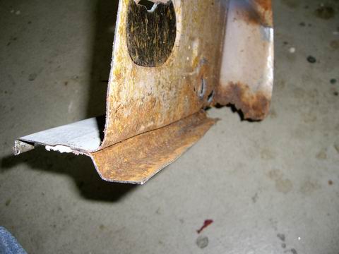
Posted by: type11969 Oct 17 2007, 09:13 AM
Jeff-
Seriously nice work, thanks for the info too. Definitely way nicer than my repairs, feel free to comment on anything I have done. I certainly don't think I will be finding any faults with your work!
-Chris
Posted by: Jeff Hail Oct 18 2007, 09:34 PM
Don't you love it when you are making a new post and the site goes down. Damn right in the middle....
Fabricated a sleeve out of 18 guage steel for the inner long.
Fit sleeve to new long section and old front long.
Drill a bunch of holes for plug welds. Apply a light coat of weld thru primer.
Start tacking..... uh oh running out of C02/ Argon and daylight.
This is supposed to be sunny California! I only get 2 hours of daylight after my day job. This doesn't fly with me!
Oh well. Saturday I will burn some more metal......
A little progress anyways.
Still a perfect door gap!
Attached image(s)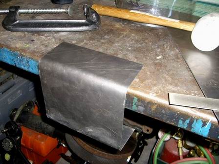
Posted by: nola914 Oct 19 2007, 12:28 AM
Jeff:
Is there a source for the horizontal and vertical dimensions (over a level plane) for the various support points under the chassis?
I have a 73 with a good motor and trans, with hell hole problems that I would like to take a crack at repairing. But down here in New Orleans, there aren't any "good" 914's that I could borrow to try and get the correct measurements.
I was thinking about building a jig from 2x10's and 4x4's, bolted and cross braced to hold against warping, and using 1/2" or 5/8" bolts for anchors and resting points. I would use a laser to true everything up.
Second hand wood is more than plentiful around here because of all of the demolition going on, so it would cost me very little to build, maybe $25 bucks for the bolts and lags.
But I need to find out the dimensions for the mount points.
It won't be as pretty as yours, but I think it would do the trick.
Posted by: watsonrx13 Oct 19 2007, 05:11 AM
Jeff:
Is there a source for the horizontal and vertical dimensions (over a level plane) for the various support points under the chassis?
I have a 73 with a good motor and trans, with hell hole problems that I would like to take a crack at repairing. But down here in New Orleans, there aren't any "good" 914's that I could borrow to try and get the correct measurements.
I was thinking about building a jig from 2x10's and 4x4's, bolted and cross braced to hold against warping, and using 1/2" or 5/8" bolts for anchors and resting points. I would use a laser to true everything up.
Second hand wood is more than plentiful around here because of all of the demolition going on, so it would cost me very little to build, maybe $25 bucks for the bolts and lags.
But I need to find out the dimensions for the mount points.
It won't be as pretty as yours, but I think it would do the trick.
David, our very own site has this information. It's under '914 info', body dimensions...
Here's the http://www.914world.com/specs/bodydims.php
-- Rob
Posted by: Jeff Hail Oct 19 2007, 09:52 AM
Jeff:
Is there a source for the horizontal and vertical dimensions (over a level plane) for the various support points under the chassis?
I have a 73 with a good motor and trans, with hell hole problems that I would like to take a crack at repairing. But down here in New Orleans, there aren't any "good" 914's that I could borrow to try and get the correct measurements.
I was thinking about building a jig from 2x10's and 4x4's, bolted and cross braced to hold against warping, and using 1/2" or 5/8" bolts for anchors and resting points. I would use a laser to true everything up.
Second hand wood is more than plentiful around here because of all of the demolition going on, so it would cost me very little to build, maybe $25 bucks for the bolts and lags.
But I need to find out the dimensions for the mount points.
It won't be as pretty as yours, but I think it would do the trick.
Underbody dimensions are very hard to find for the 914. I think you can still get them from Tru-Way on CD. Fortunatly the 914 has a symetrical body meaning center -side to side can be done by cross measuring. Datum measurements (from a flat plane) for height are easy if the body is stripped. By 1970's standards the 914 platform is considered stiff when the roof is bolted on. The dimensions found on this site are 90% upper body and I they will get you where you need to be. For the underbody it is really simple. A 914 is essentially just a sheetmetal box and it has a flat bottom.
You could make a platform from wood 4x4s but it will change dimension with heat and humidity. Probably not enough to loose sleep over.
If you have good jack pads that aren't damaged you can use the 4 locations under the tub to build your foundation. Unless you are cutting out major structural parts you should not get into trouble. If you are just repairing and replacing parts all you need is to support the body equally.
If you have an extra eighty grand you can get one of these (kidding)
Attached image(s)
Posted by: Jeff Hail Oct 20 2007, 09:57 PM
Second time the site went down trying to post pictures. Lets try this again.
The "House of Steel" is open". Lets burn some metal!
Finished welding the sleeve to the inner long. I still finish metal that isnt seen on the outside. I know it's there and has to meet my standard of quality.
Welded all the plugs on the outside and butt welded the seam. Almost invisible. The way it should be. Grind everything smooth and coat of etching primer is all it needs.
Really windy in Santa Clarita today. Those Santa Ana's are mighty. Fist time in my life I had to turn the diffuser gas up to 40CFH!
A few tips for non experienced welders out there:
When welding inverted you want to strike a fast hot arc. Cut your wire with a pair of diagonals everytime you strike an arc. This will create a fast burn in and reduce pooling and puddle sag. Gravity is working against you when you weld upside-down. If you don't cut the wire everytime you have a small ball of oxidized metal on the tip of the wire. This has to burn off first and slows penetration. Cut the wire each time! It will make a good clean fast weld.
Attached image(s)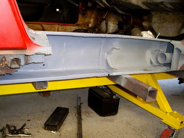
Posted by: degreeoff Oct 20 2007, 10:28 PM
 I just have to say....'right on my man' wish I had that kind of patience...mine will last for 10 yrs if I am lucky but hey, then I'll do it agin!
Posted by: Jeff Hail Oct 20 2007, 10:45 PM
Threw a second coat of primer on before it got dark. Came out clean.
Attached image(s)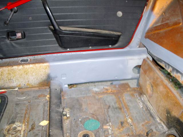
Posted by: Jeff Hail Oct 20 2007, 11:13 PM
A little more on welding thin sheetmetal:
Use weld thru primer. Do not be concerned about if you have sprayed on enough. Less is better. When you weld you are going to burn off the primer at the weld zone anyway. The zinc is only there to surround the weld zone once burned through and reduce oxidation.
I recomend scratching off any zinc primer at the weld zone area. You will get a faster hotter arc and will have less contamination resulting in a stronger flatter weld. When you are done take a Roloc disc and remove any left over weld thru primer in the area. The high zinc content has poor adhesion properties so you do want it left over as a primer for the surrounding area's.
Use a proper respirator. Zinc Oxide fumes are hazardous at least and can kill . There is no cure for heavy metal poisoning. Basically what zinc does is, it causes the bodies natural defenses to go into overdrive. Thus the same as other heavy metal poisoning. This has been called in the past "Monday Morning Fever", "Brass Fever", "The Brass Shakes", "Foundry Flu", etc. . .
Like a condom use protection. I cannot emphasize enough on safety.
Posted by: rjames Oct 21 2007, 12:24 AM
Any advice on which brand of weld through primer to use?
Do the ones in the spray cans work well enough?
Great thread Jeff!
Posted by: Jeff Hail Oct 21 2007, 12:35 AM
Any advice on which brand of weld through primer to use?
Do the ones in the spray cans work well enough?
Great thread Jeff!
I use Wurth products but I think any Zinc rich primer will be fine. Spray cans are sufficient as you do not need a lot. Just a press of the nozzle is enough. It's not a metal primer so don't be concerned about coating an entire part. Just a dusting around the weld area is all that is needed. Too much and it creates penetration issues. Any left over should be removed and a good metal primer should be applied after grinding.
If you are seeing a green flash or sputtering when striking an arc you are using too much zinc primer.
Posted by: rhodyguy Oct 21 2007, 10:18 AM
this thread NEVER ceases to amaze!! wow. the astro scraper @$40 and change is a must have. please (if you're so inclined), submitt a write up for the classic forum. you're providing examples of first rate work, pictures, and text.
k
Posted by: majkos Oct 21 2007, 10:30 AM

Your tips has saved me 20 years of trial and errors!
First rate indeed!
Posted by: Thomas J Bliznik Oct 21 2007, 10:51 AM
Mr. Jeff Hail
Your metal work is magnificent I like the way you explain things to us amateurs. It's so easy to understand.
Have you ever thought about writing a "Metal How To Book"?? It would be a great seller. This would be a great EXCELLENCE magazine how to article. Are you listening Pete??
Thanks for posting. ![popcorn[1].gif](style_emoticons/default/popcorn[1].gif)
Tom
Posted by: StratPlayer Oct 21 2007, 01:25 PM
This is truely amazing stuff here. My hats off to you sir on some fine work, and a gallant man to take on a project like this.
Posted by: Gint Oct 21 2007, 05:22 PM
Nice work. I wish I had the talent to do all of that work myself.
Posted by: Jeff Hail Oct 21 2007, 06:37 PM
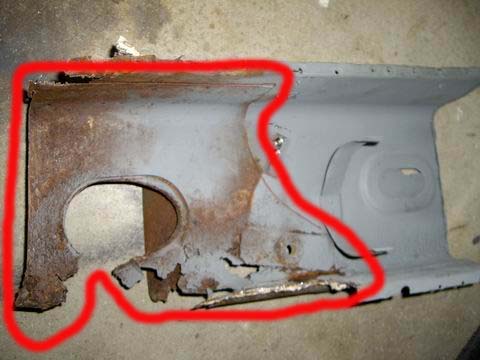
A valid PM was sent to me by Wes in reference to metal fatigue. On my previous post I may not have been clear but I will try to explain by example.
I referred to high stress/ high flex areas and double walls.
Where the inner long come's together with the rear frame rail it was double walled by the factory highlited in red.
If I were to just weld the inner long to the rear frame rail without the double wall it would be a very flexible joint and eventually fail. This would be compounded by suspension movement and engine weight and torque. This area is where the rear center section of the tub (torque box) ties into the rear structure of the vehicle. This area needs to be as strong or stronger than the factory designed it to be.
Everytime the suspension compresses this area is subjected to load. Everytime the vehicle is launched it is subject to load.
These parts are made of 18 guage sheetmetal which is not very thick. The area where the inner long ties into the rear frame rail is subject to high flex. The load of the rear section of the unibody is partially transfered to the long connection.
The long is a straight box and then kicks up into what is known as the Hell Hole. If rust of damage occurs at this area it will or has become fatigued with use. In a worse case scenario the car will sag. First because the supporting metal in this area has disappeared and second what metal left is supporting the weight of the car and suspension loads. It give's way. This is usually observed by a tight door gap in a very bad case of rust.
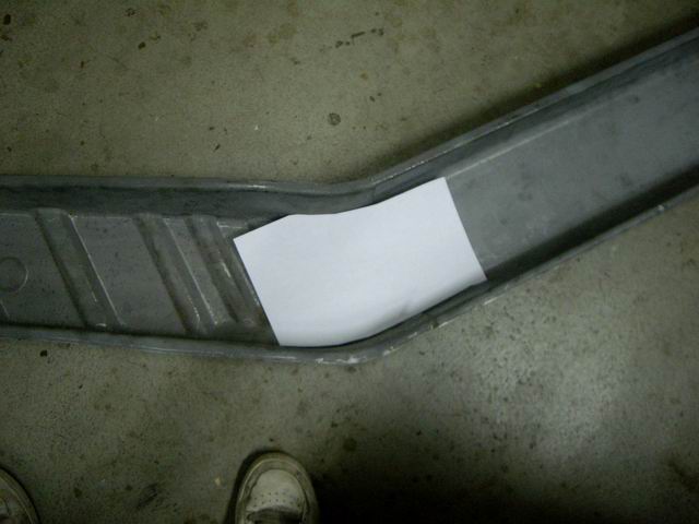
The example shown with the "paper template" would reflect the double wall at this connection. The purpose of the double wall is to spread the load at the joint into a larger area. This will reduce the load carried by the long/ rail connection at the seam/ weld area only. Because the rear rail is kicked up it acts as a lever pushing up each time the suspension compress's. The second wall controls the allowed flex in this area reducing fatigue that the long/ rail joint is subjected to.
An easy understanding would be a paper clip. A large paper clip is about 18 guage or so. If you straighten it out and then bend it back and forth it will break in two. Now take 10 paper clips and do the same thing all grouped in a bundle. It will be more difficult to bend 10 bundled and the bend area is now radiused into a larger area. If the paperclip is allowed to flex in a small area versus a larger area it will take less cycles to break. The same principle with sheetmetal applies except the long is comprised of a 3 sided box speading the load into a larger area into the wheelhouse and firewall connections.
Hope this helps
Attached image(s)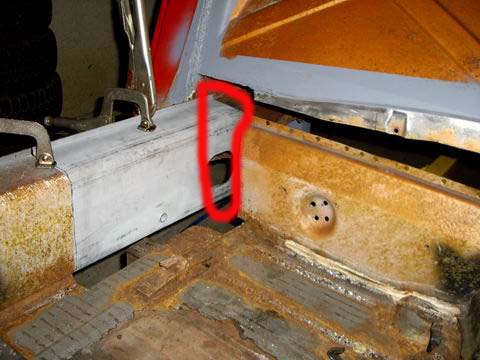
Posted by: Wes V Oct 21 2007, 07:46 PM
A valid PM was sent to me by Wes in reference to metal fatigue. On my previous post I may not have been clear but I will try to explain by example.
Thanks for not taking the PM the wrong way!
But that still doesn't answer if it's possible to swing by!
Wes Vann
Posted by: Jeff Hail Oct 21 2007, 07:47 PM
Another example of double walled panels.
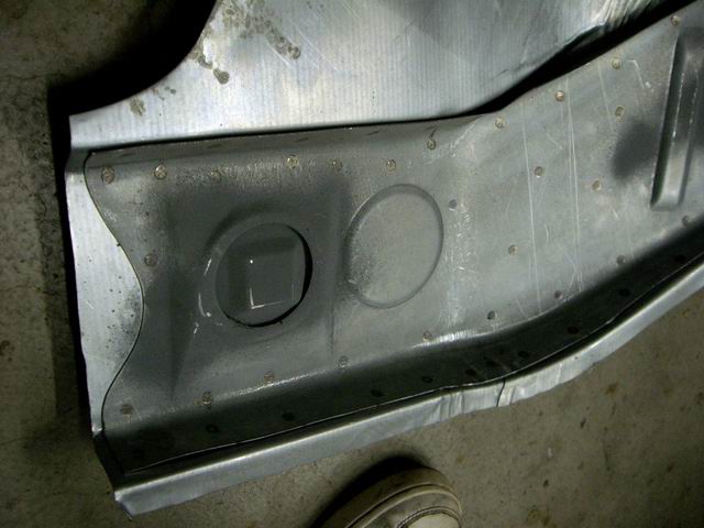
The right wheelhouse assembly. This is an AA part. Notice where the double walls are? Extra layer added all thoughout the rail area which supports the the motor mounts and suspension console also.
Sorry George, pretty rough part if you ask me. If the guys used oil or wax in the dies those hidious wrinkles at the battery tray area would not be half as bad!
Attached image(s)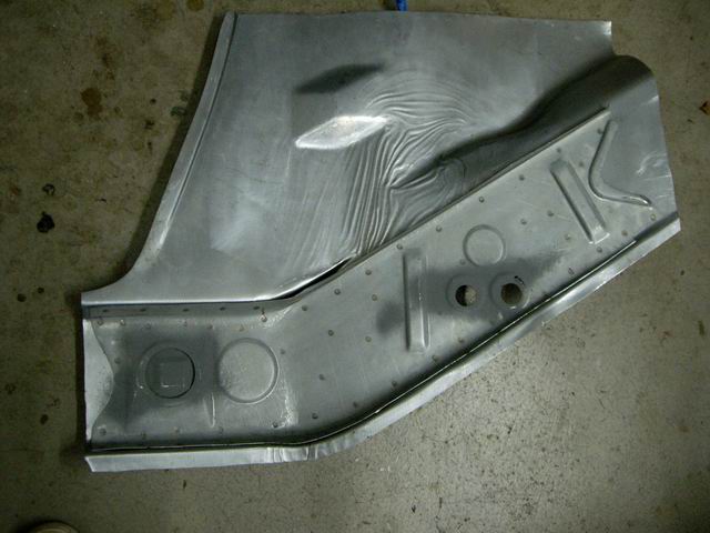
Posted by: Jeff Hail Oct 26 2007, 11:50 PM
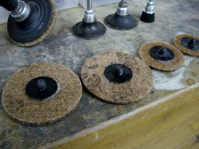
type11969 has a few questions regarding Roloc disc's
3M is not the only one who makes the threaded plastic hub abrasive discs that fits the standard Roloc arbors/adaptors. I use a few off brands as well. The ones I use more of are for clutch and brake disc conditioning. Same fine grits available as 3M for 1/5 the price. I find them in bags of 100 for about $20.00 One of my local suppliers retired so I now have to order them from an internet supplier ( Autobody Tool Mart) which is a great supplier of body needs. You can find them at www.autobodytoolmart.com or 1-800-382-1200
The Rolocs disc's and arbors are pictured below. The arbor adaptors are the same for small sanding disc's so everything is a quick change universal fit. These are the standard of the autobody industry. Very convenient and long lasting.
The part # for the (3M) arbor/ backing pad's are:
1 inch- 05538
2 inch- 05539
3 inch- 05540
These are 1/4 inch shanks. I included a picture of the die grinders they fit.
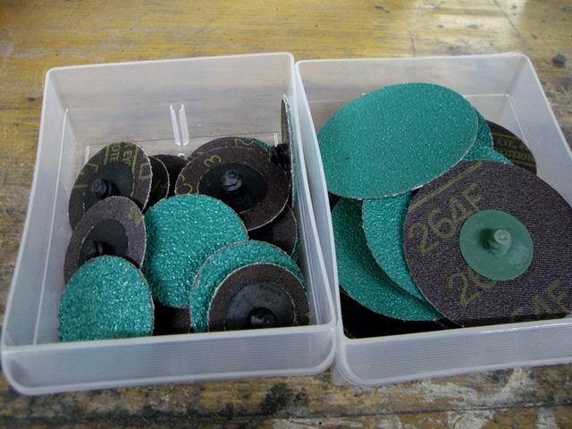
The disc's are available in both sanding discs and conditioning disc's.
Sanding discs are available in 24,36,50 grits and are round sand paper disc's.
(The Green Corp's- 3M)
Conditioning disc's come in fine , medium and course. These are the one's I prefer as they last long and do not thin metal. They smooth and clean the surface. They look like old dirty panty hose spun with resin. The fine grit doesn't leave sand scratches and requires almost no finish work.
The big nasty looking black disc's on the right are 3M Clean and Strip disc's. Two kinds are available. Roloc standard and the big ones as pictured. These take a different arbor which is 1/4 inch that fits any die or angle grinder. The same arbor for these big disc's would be used on cut-off wheels or weld grinding disc's. These are for aggressive coating removal.
If you are stripping large area's I would use Aircraft Stripper. Work smart not hard. If you are stripping thin gauge exterior body panels (fend's , door's qtr's, hood's etc) you do not want to apply heat with rotating abrasives. A lo speed DA is ok but still a lot of work. Heat warp's. Use stripper. If you are stripping longs, trunks and other area's that may have thicker metal and are not normally visible on the exterior then alternative abrasives such as Clean & Strip disc's are fast to get down to bare metal.
Attached image(s)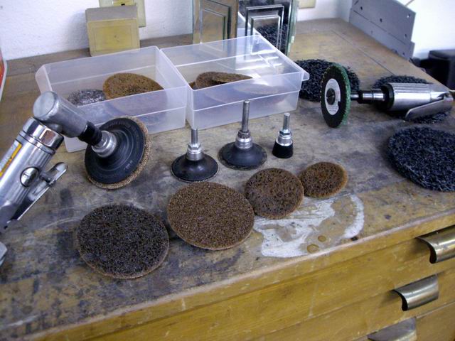
Posted by: type11969 Oct 28 2007, 08:22 AM
Thanks Jeff!
Posted by: Jeff Hail Nov 3 2007, 07:45 PM
Didnt get anything done for two weeks. Fire's, house stuff and other distractions took over.
Had a nice solid 4 hours to play today.
Cut and trimmed the remainder of the old panels, flanges and junk out.
Attached image(s)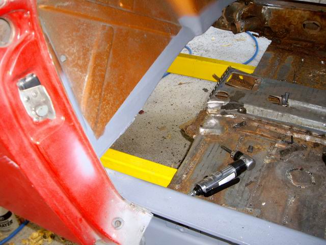
Posted by: Jeff Hail Nov 3 2007, 07:47 PM
Prepped the flanges and seams for the inner and outer firewalls.
Attached image(s)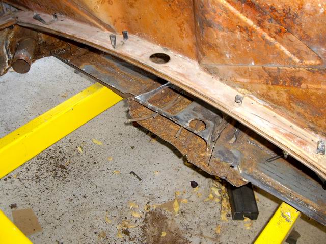
Posted by: Jeff Hail Nov 3 2007, 07:50 PM
Passenger side of the tunnel was just surface rust and came right off with a conditioning pad. Good solid clean metal.
Drivers side very rear of the tunnel has some corrosion that I will need to replace a small section of the last 2-3 inches at floor flange.
It's only metal I tell you!
Attached image(s)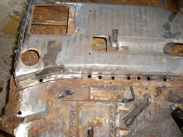
Posted by: Rand Nov 3 2007, 07:58 PM
Just wanted to give you a virtual high five here Jeff. This is good stuff. Your thread is destined to be a classic that will help a lot of people. Thanks for digging in deep and sharing the progress with us.
Posted by: Jeff Hail Nov 3 2007, 08:06 PM
Mocked up the inner and outer firewalls to see how everything fits. No welds just loose.
The outer is a NOS piece and the two lower inners are AA. The AA parts fit pretty damn good. All the locating holes and boss's line right up with the original piece.
(George I am impressed)
Before I weld these in I will repair the tunnel. I also need to modify the outer firewall because my car is a 75 and the NOS part is for an early car. I will resize the shifter bushing reinforcement to match the later bushings.
I will also need to repair the tunnel lines. I had to cut them to get the PO's previous horrors out of the way. McMaster-Carr has the correct size tubing available. I have a few improvements in store from the factory design anyway.
The factory E brake handle, location, tubes and elbow's are going away. I have a 1995 993 E Brake assembly that will go between the seats.
Attached image(s)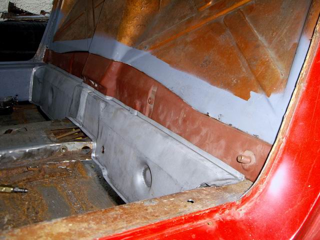
Posted by: Jeff Hail Nov 3 2007, 08:08 PM
Kind of looks like a 914 again!
Still lots to do. Stay tuned for the next episode of "Fun with Clecos"
Attached image(s)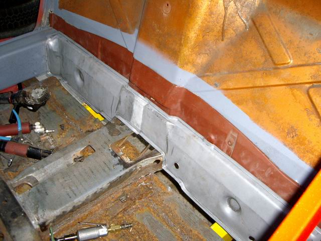
Posted by: Jeff Hail Nov 3 2007, 08:26 PM
One last thing for the day. It is possible to get the J-Tubes out without opening up the longs. My passenger side is open and the driver side is still closed for now. They have 2-4 spot welds holding the bracket. It can be wrangled out.
Get them back in with the longs closed up? Optimisticly I think it can be done. If the silencer pulls off at the front tube is another story.
Posted by: Jeff Hail Nov 3 2007, 09:01 PM
Just wanted to give you a virtual high five here Jeff. This is good stuff. Your thread is destined to be a classic that will help a lot of people. Thanks for digging in deep and sharing the progress with us.
To quote my good friend Mac Tilton "knowledge should be shared...unless of course it is a competing race team then throw tarps over everything".
Posted by: Jeff Hail Nov 3 2007, 09:12 PM
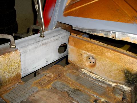
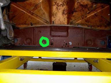
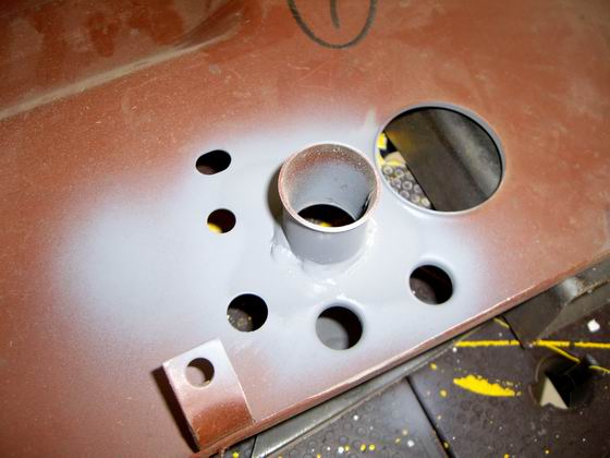
Anyone with an early car know what these holes are for? The holes line up on the inner fire wall and inside the shift rod housing on the outer firewall.
I checked all my disassembly photo's and do not see it on the late body.
Just wondering what they are for?
Attached image(s)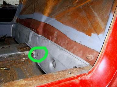
Posted by: 1970 Neun vierzehn Nov 3 2007, 11:58 PM
Anyone with an early car know what these holes are for? The holes line up on the inner fire wall and inside the shift rod housing on the outer firewall.
I checked all my disassembly photo's and do not see it on the late body.
Just wondering what they are for?
Jeff,
First, let me heartily applaud your work. The scope, quality, care, attention to detail, and the sheer magnitude of the project are all evident in your (also quality) photos. I salute you.
With regard to the extra hole, in what the Porsche parts book refers to as "back wall, lower part", there is a part (and number) assigned to the /6 (1970 only) that could possibly be what you are installing, which was originally intended for use in a /6. I can't speak for the differences between the /4 and /6 down in the rear bulkhead/backwall where you are working. Sounds like it could be transmission related. The part # is 914.501.007.10
Paul
Posted by: sixnotfour Nov 4 2007, 10:40 AM
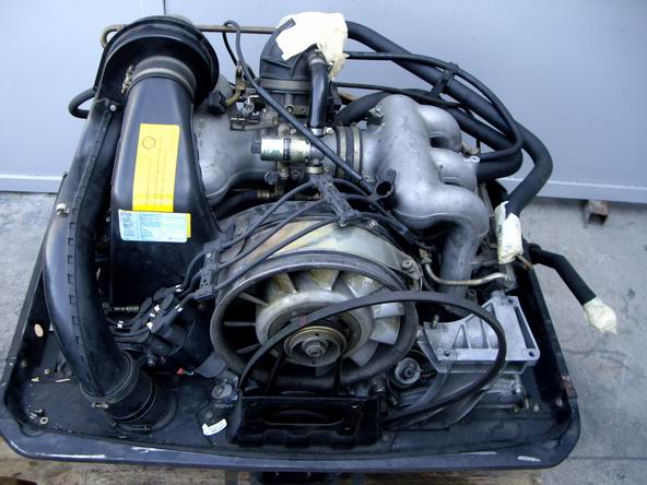
Yes, that hole is for a pivot ball , But for 4 cylinder only. The six uses a simple two bolt type u-joint .
Here is the six wall peice , It has the motor mount welded to it. (note: the black piece is the part that bolts to engine.)
Keep up the great work.
Attached image(s)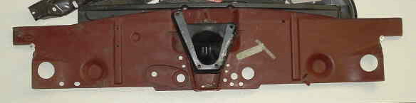
Posted by: Wes V Nov 4 2007, 12:11 PM
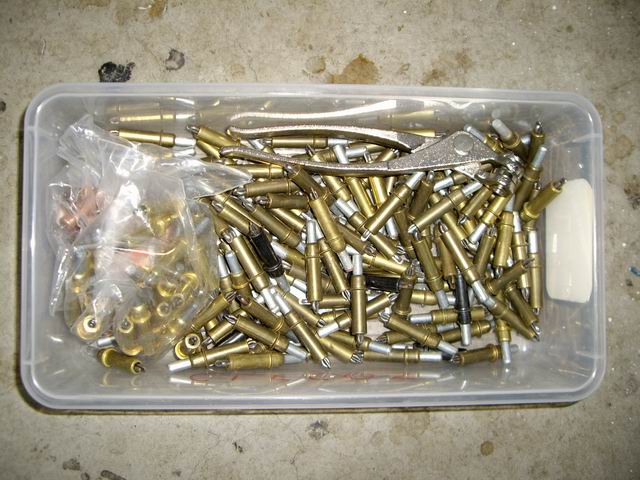
For those that may not know;
Clecos are clamps that are used as temporary pop rivets during the fabrication and fitting of parts.
If you look at the photo Jeff posted showing the plastic box full of Clecos, you will see what looks like a set of plyers. That's the tool that is used to install and remove the cleco.
Wes
Posted by: davep Nov 4 2007, 01:32 PM
Jeff, can you take some good photos of that panel before you install it, and post them in the parts vault please.
http://www.914world.com/bbs2/index.php?act=SF&s=&f=46
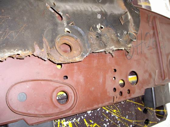
Posted by: Jeff Hail Nov 4 2007, 07:41 PM
Stuff that is easier to do now than later.
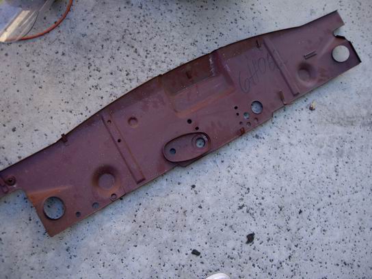
I am using an early firewall (PN# 914-501-119-10) which is for a 914/4 thru 1971 to be put on the 1975 body.
The NOS firewall does not come with a speedo cable spigot tube. The early firewall has some differences. I will update and modify according to my build.
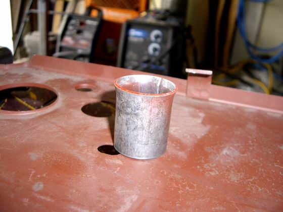
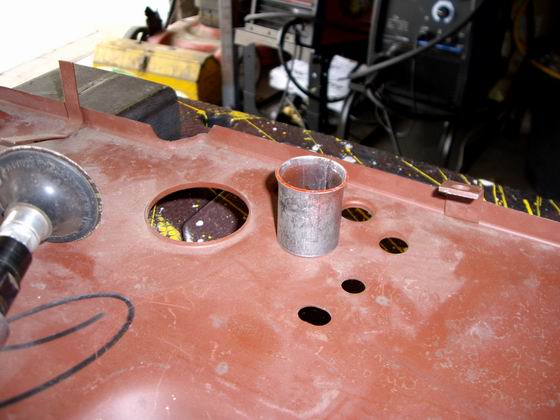
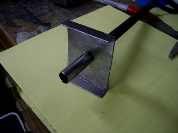
The Speedo Cable Spigot Tube
Lets build one..........
The old section versus the replacement.
Attached image(s)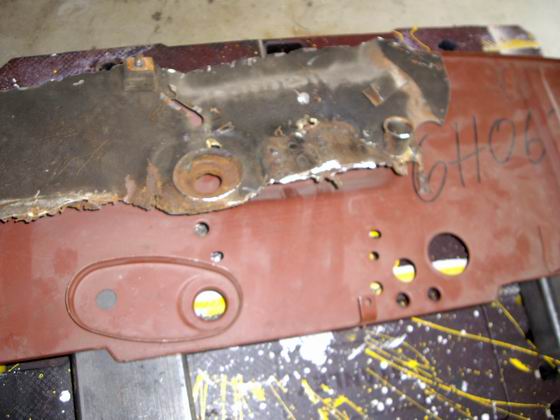
Posted by: Jeff Hail Nov 4 2007, 07:46 PM
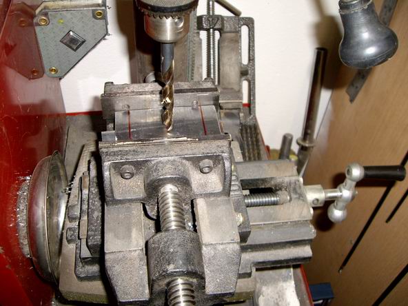
Wondering how I flaired the tube? After rummaging through the tool and junk box's for something shaped like a ball or cone I decided on a ballpeen hammer.
I knew that round end was good for something!
Put the 1-1/4 inch long stub on the ground. Put the round head inside and smacked it a few times with an even bigger hammer until I reached the desired shape.
That myth of hitting a hammer with another hammer is BS by the way.
Attached image(s)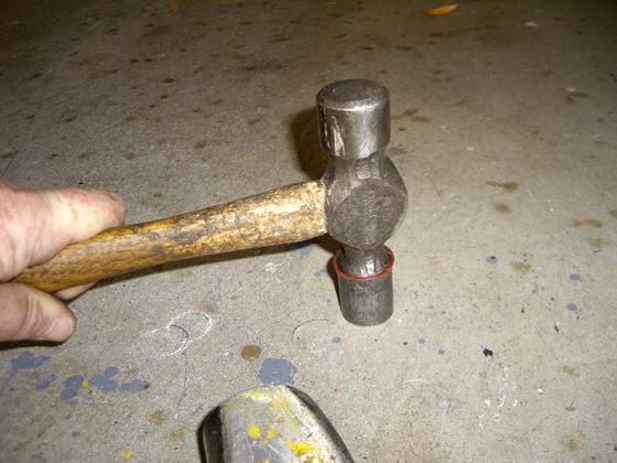
Posted by: Jeff Hail Nov 4 2007, 07:48 PM
Mig welded the spigot to the firewall and some primer. Done!
Don't forget to remove any burrs or sharp edges from the inside of the tube.
Attached image(s)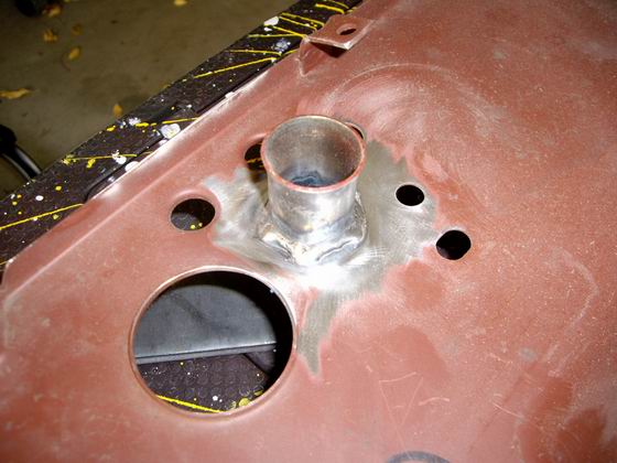
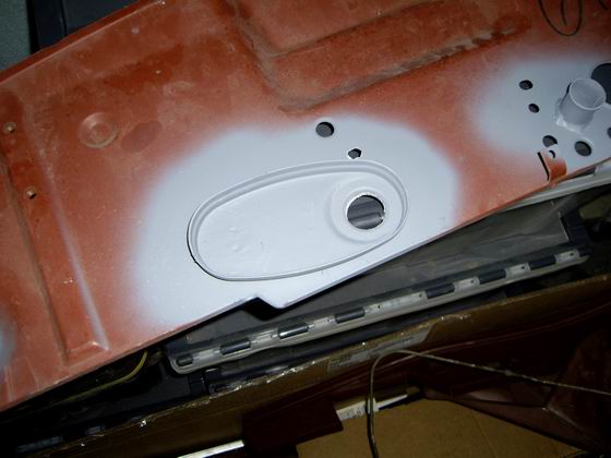
Posted by: Jeff Hail Nov 4 2007, 07:55 PM
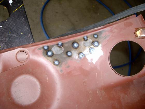
Moving along to the E-Brake Cable delete.
Cut out a rectangle of sheetmetal and punched some holes in it.
Spot weld it to the firewall.
I almost tacked it to the wrong side! Ooops. Caught in time.
Attached image(s)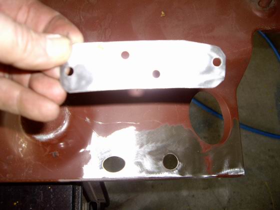
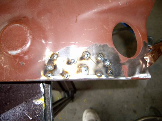
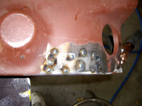
Posted by: Jeff Hail Nov 4 2007, 08:03 PM
A little finishing with a grinder and conditioning pad. Looks like factory "knockouts" on the engine compartment side. Porsche never had knockouts here except for the 6 cylinder oil tank holes on the driver side wheelhouse. Still looks clean.
If for some reason my E-Brake conversation to the 1995 993 center pull becomes a problem I can always resort back to the original design and add the elbows back in with minimal work. Always plan ahead for curves in the road.
Attached image(s)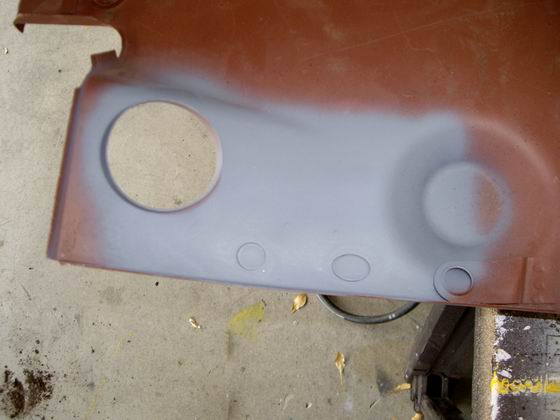
Posted by: Jeff Hail Nov 4 2007, 08:20 PM
Some more holes that need to go away.
The mystery hole to the left of the shiftrod exit on the outer firewall. Gone!
Inner lower driver side firewall matching mystery hole. Gone!
I kind of like the "knockout look". These don't show so I am not going to waste time metal finishing the recess.
Also the two holes on the inner firewall for the E-Brake cable delete. Gone!
Same procedure. Fab a plate and punch some holes. Spot weld it to the backside.
Wait! those two holes have a raised boss. Better get rid of those also and make it smooth. Hammer and dolly.
A great tool is the Punch/ Flanger. On one side it has a hole punch which really is an effortless time saver. After drilling out over 500 spot welds at this point in the project I look forward to it. On the other side of the head is a flanger. Great for lapping panels and floors. Makes a nice finished step in sheetmetal and looks professional.
Attached image(s)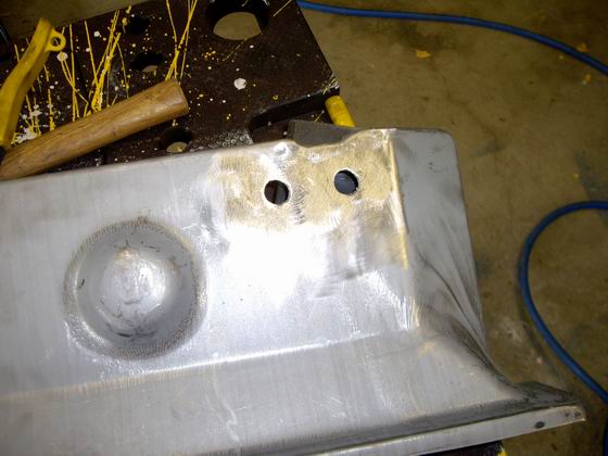
Posted by: Jeff Hail Nov 4 2007, 08:30 PM
Corrosion Protection:
I cannot stress enough about corrosion protection on a 914. These little buggers rust from the inside out.
All area's that were welded get a coat of primer. I then went over the primer and spotted with Wurth Seam Sealer. This sealer looks like the OEM sealer Porsche used on all the seams and under the rockers where the floor connects.
Today it is the factory recommended sealer for Porsche, Mercedes and BMW.
As Snoop Dog would say "this is the shizzle". It cannot be beat.
Most of the area's coated will never be seen so appearance wasnt a priority. Doesnt matter, it still needs to be sealed. Primer alone doesnt cut it. Even between the firewalls a few minutes spent will last a lifetime.
Attached image(s)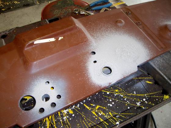
Posted by: Jeff Hail Nov 4 2007, 08:38 PM
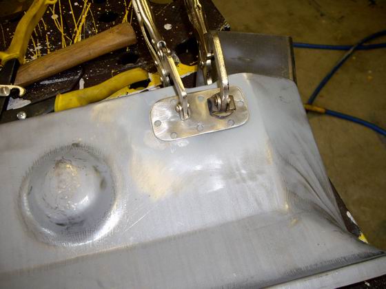
I decided to leave the early boot cup on the shift shaft housing instead of swapping to the late round style. The early firewall has about 40 resistance welds holding it in and would do more damage to the firewall removing it and installing the later one so I left it in.
Notice the hole to the left of the shift shaft has been deleted.
Fitting a bushing to the shift shaft will not be an issue. The early bushing is larger and can easily me made from Delrin or a sealed bearing installed. I have seen the Patrick Motorsports Bulkhead Bearing on another car it it is superior to the OEM application in every way. For $43 the PMS is a no brainer.
Attached image(s)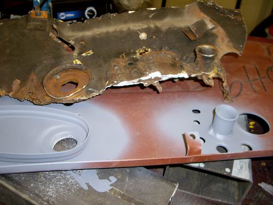
Posted by: Jeff Hail Nov 10 2007, 09:50 PM
Didnt get any work done on the tub during the week and forgot to order the tubing from McMaster Carr soooooooooo I can't work on the throttle and clutch tubes. I can't finish the inner and outer firewalls until the tunnel work is completed yada yada.......
Ok sheetmetal happens! Move forward to the mid-floors.
I like to focus on an area and set small goal's. More seems to get done that way instead of jumping around.
Lets get to work.
Today I worked on the passenger front 1/4 floor, tunnel and floor crossmembers. Stripped everything to bare metal. I was surprised this area was not bad at all. I little flash and surface rust but easily prepared. I still have to section a piece in the drivers side rear tunnel at the firewall junction due to corrosion but that can be done later. Might as well get some thing done while I am waiting for parts.
The driver and passenger side rear floor will get replaced. I do not want to make the cut until I have the firewall tacked in and positioned.
I stripped the rt/ qtr front floor with a scraper long ago. I then went over it with a 3 inch wire wheel on a die grinder to remove any scale. Then removed all the sealer up to the front bulkhead with the Wurth (Flail). Any remaining glue/adhesive for the floor pads removed with Lacquer Thinner. Then used a conditioning pad on a die grinder to knock everything down smooth.
I want to leave as much original zinc and factory primer as possible since it is still in good condition up to about an inch in front of the floor/ seat crossmember.
Attached image(s)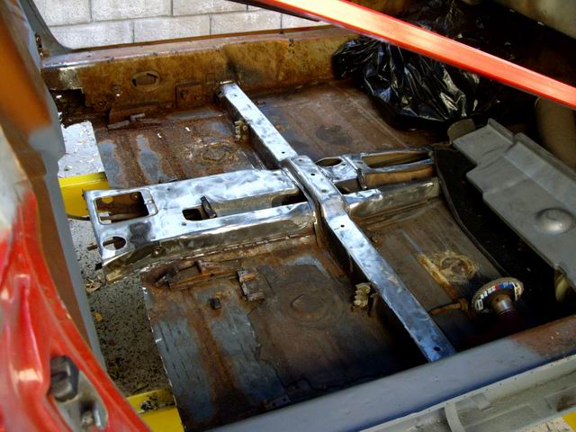
Posted by: Jeff Hail Nov 10 2007, 10:14 PM
Again the rear floor behind the seat crossmember is getting replaced. It's only function is to link the longs to the tunnel for support while I work in other areas for now.
Back to the front right 1/4 floor area. Stripped and all tunnel connections (flanges) prepped with a solution of phosphoric acid/ zinc phosphate (same thing as Metal Ready), let sit for a half an hour and go hit a couple cups of Java.
Once the etching solution has converted any flash rust that I couldn't remove by machine (Which was very little) I wipe with a dry towel. The solution is still working. Then I go over it with a wet rag and let it air dry. I really don't like introducing water to the interior but it is the only way to make sure any residual is nutralized. I then force out any liquid residue with compressed air that may be hiding. I aid evaporation with a propane plumbers torch just warming any area's that liquid may be hiding in the tunnel/ floor flanges.
Attached image(s)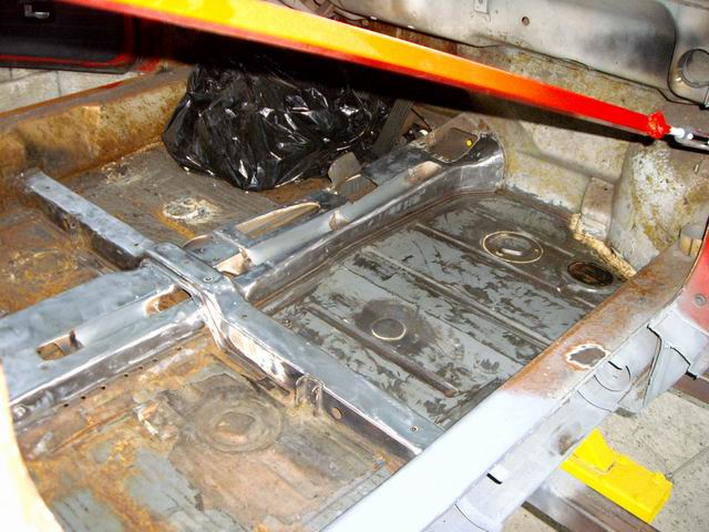
Posted by: Jeff Hail Nov 10 2007, 10:24 PM
Once everything has sat a little while it is then sanded. First 220 and then 320 to accept epoxy primer for proper adhesion.
If you want primer to stick don't put it directly over a converted surface. You need to sand and abrade the surface first. Not course enough to remove any conversion coating but enough to rough it up.
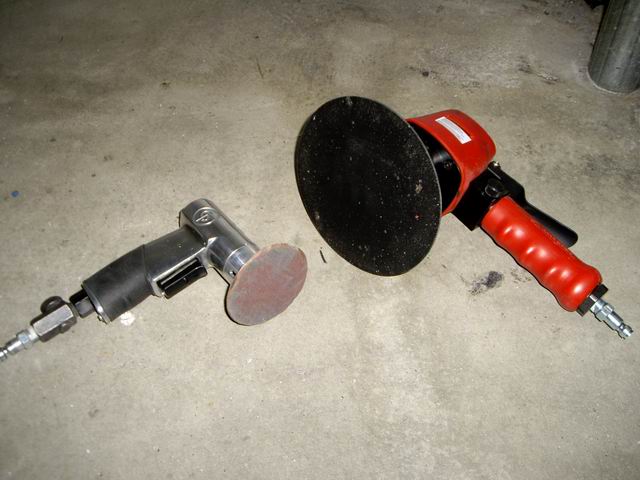
The Mini DA works great on the floor's. It's small enough to get into the recess's yet still large enough to work quickly. A normal DA sitting next to it's little brethren.
Attached image(s)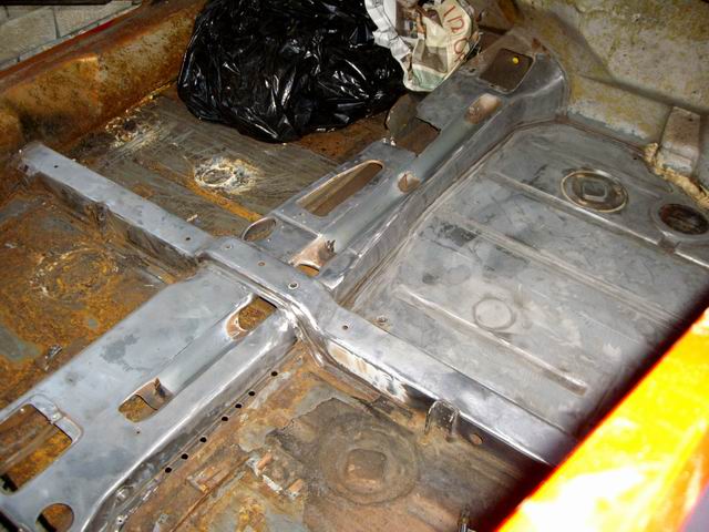
Posted by: Jeff Hail Nov 10 2007, 10:48 PM
Working in smaller area's makes it easier to manage and focus than large surface area's. Might be some overlap but when a week may go by between work on the project results happen. Unless you are doing this in a production shop set goals and smaller area's to work on.
After the application of epoxy primer.
Helpful advise....DO NOT SPRAY THIS TYPE OF PRODUCT UNLESS YOU HAVE A POSITVE PRESSURE RESPIRATOR.
A PPR uses a forced fresh air supply and is the only way to save your lungs, brain and life.
Catalyzed Epoxy Primers and Isocyanates will take your life if you do not follow the proper safety measures for body and respitory protection. No car is worth your health, brain or life!
Attached image(s)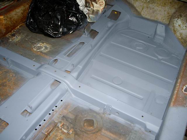
Posted by: stateofidleness Nov 10 2007, 11:15 PM
hey jeff, question. you are about where im at on my interior and im a complete noob to this stuff.
now that i know that it is ok to primer a little at a time, will you go back and reprimer the entire thing when you're done or only the areas not done?
another thing, those removable hole covers in the pans on mine are all bent and mis-shaped. is it better to try to reshape them and get a good seal on the hole (while also needs to be straightened out) or just weld a piece of flat sheet metal over the hole?
i did 2 coats of this rust converter which turned the "rust" to a primer black color. so all i need to do is light sand it and then prime? or should i do that acid thing and then sand?
really impressed with your work and focus. very inspirational.
Posted by: Jeff Hail Nov 11 2007, 12:30 AM
hey jeff, question. you are about where im at on my interior and im a complete noob to this stuff.
now that i know that it is ok to primer a little at a time, will you go back and reprimer the entire thing when you're done or only the areas not done?
another thing, those removable hole covers in the pans on mine are all bent and mis-shaped. is it better to try to reshape them and get a good seal on the hole (while also needs to be straightened out) or just weld a piece of flat sheet metal over the hole?
i did 2 coats of this rust converter which turned the "rust" to a primer black color. so all i need to do is light sand it and then prime? or should i do that acid thing and then sand?
really impressed with your work and focus. very inspirational.
Being it is winter hours I find my daylight is short. I try to set a goal I know I can complete in a given amount of time.
When I repair an area such as the right front floor I knew I am going to have some overlap into an adjacent area. No big deal. Any primer overlap/overspray will sand off and be re-applied for instance when I do the drivers floor. I am only talking a few inches of coating so I do not worry about masking anything off here.
The need to get this area primed was it is bare and we have been having humidity in the air lately in sunny California. Moist cold air and bare metal are not friends even if it has a zinc coating.
As far as the factory resistance welder access covers I did not remove them. I removed most of the surface sealer around them but did not find any scale or corrosion. Obviously they have not leaked. I left them in and primered over them. I will apply some sealer to replace what was removed. The small 3 inch cover next to the long on mine was a little tweaked. I just took a hammer and dolly to flatten it out. No rust so no need to remove it. These will also have new seam sealer applied over these.
Rust converter is the "acid thing". You are two step's ahead.
I have to say this rust converters are a misconception. They do not turn rust back to good metal. All that is happening is the iron oxide (rust) is being converted to an iron phosphate "layer" ( a different kind of rust) similar to rust bluing on a firearm. The key to rust converters are the chemical conversion of surface scaling and then sealing it from oxygen via zinc phosphate. Without oxygen rust cannot continue. Adding a zinc layer by conversion is part of the sealing process. Zinc does not oxidize like iron will. Zinc is also used for adhesion. Best bet is to remove as much rust as possible with wire wheels, conditioning and grinding disc's. If metal has become structurally unsound, brittle or weakened due to corrosion the only way to properly repair it is to replace it. A good example is if you look at metal that is rusted and it looks like a bunch of rotten leaves in layers it is done and cannot be saved. Pits and deep scale are another thing. These can be normally ground away and or filled with welding if enough metal is present.
Ok - If it looks like all the rust is converted to rough black primer I would use an abrasive from 150 to 220 grit paper on it and score the surface lighly, just skim it. If you start seeing carrot colored rust again it was not treated sufficiently. If you see this do the conversion again. Then lightly go over it with 320. Do not worry if you remove a little of the coating. Then prime it quickly.
Another thing on converters make sure it is nutralized correctly. If it is not done right you will end up fighting two kinds or corrosion. Rust and chemical.
Can you tell I am not a big fan of rust converters? They do have there place though. Something I learned a long time ago welding. Steel melts and rust will burn (oxide).
Posted by: Twystd1 Nov 11 2007, 01:54 AM
Jeff,
When I was up at your house checking out your teener. I didn't realize how proficient you were at the written oratory thing.
This thread is invaluable to guys like me.
I can't thank you enough for doing this. Tis very good stuff indeed.
Clayton
Posted by: Twystd1 Nov 11 2007, 01:55 AM
Before I forget............
I owe you a cup "O" coffee.
Can't wait to get together and buy ya one....!!!!!!!!!!
Clayton
Posted by: HalM Nov 11 2007, 08:29 AM
Just tuned into this thread and al I can say is WOW! Terrific job.
Posted by: restore2seater Nov 11 2007, 12:27 PM
Helpful advise....DO NOT SPRAY THIS TYPE OF PRODUCT UNLESS YOU HAVE A POSITVE PRESSURE RESPIRATOR.
A PPR uses a forced fresh air supply and is the only way to save your lungs, brain and life.
Catalyzed Epoxy Primers and Isocyanates will take your life if you do not follow the proper safety measures for body and respitory protection. No car is worth your health, brain or life!

Jeff,
What brand of respirator is this? If you don't mind me asking what was the cost?
I've looked for those types of respirators and most are over $1,000.
Posted by: Jeff Hail Nov 11 2007, 02:43 PM
Helpful advise....DO NOT SPRAY THIS TYPE OF PRODUCT UNLESS YOU HAVE A POSITVE PRESSURE RESPIRATOR.
A PPR uses a forced fresh air supply and is the only way to save your lungs, brain and life.
Catalyzed Epoxy Primers and Isocyanates will take your life if you do not follow the proper safety measures for body and respitory protection. No car is worth your health, brain or life!
Jeff,
What brand of respirator is this? If you don't mind me asking what was the cost?
I've looked for those types of respirators and most are over $1,000.
Sata Vision 2000. They retail for $800, I found mine on ebay for $300 new in sealed box.
Posted by: Jeff Hail Nov 11 2007, 03:11 PM
Before I forget............
I owe you a cup "O" coffee.
Can't wait to get together and buy ya one....!!!!!!!!!!
Clayton
Back at ya Clayton
Attached image(s)

Posted by: Jeff Hail Nov 11 2007, 10:49 PM
"While you're in there"
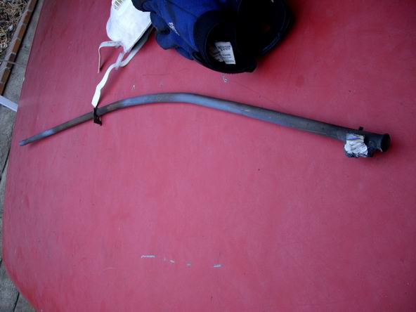
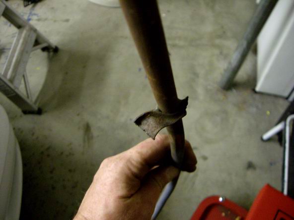
Had second thoughts on the prior owner repairs to the clutch and throttle conduits.
Someone put about 2lb's of crap in the tunnel. Looks like it was repaired twice. First time a gob of coat hanger and fire were done, then later a bracket added with a wire welder. This has got to go!
I can hear Steve Martin now....."stay away from the tubes"!
Clutch conduit removed. Pretty easy actually.
The front was held in pretty well. Looks like the second repair was overkill.
I still do not like it.
The rear clutch tube bracket was intact but the factory bracket which looks like formed 20 gauge steel is going to get a make over. Too wimpy in my opinion.
I am going to leave the throttle cable conduit as is. It is intact and does not have pressure on the tube like the clutch cable does. It is still solid. One less thing to replace.
Attached image(s)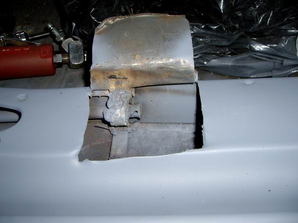
Posted by: Jeff Hail Nov 11 2007, 11:00 PM
Already ordered some tubing from McMaster-Carr.......................
Lets make a couple of clutch tube brackets. Take some measurements.
Cut out some burly 16 gauge steel. Drill the hole and form the bracket.
Instead of 3 mounting point's I will have 4 (front, middle and rear, plus the firewall. It will never break loose.
Attached image(s)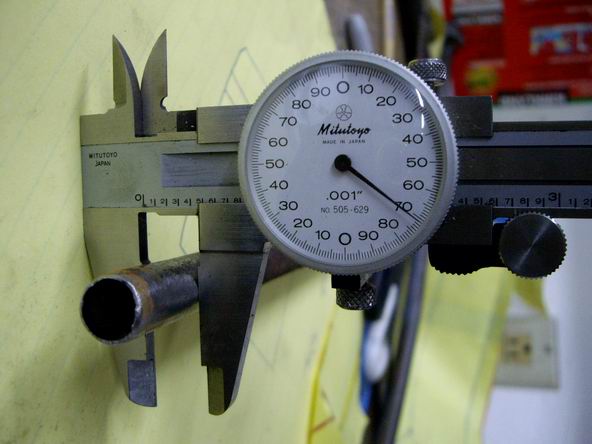
Posted by: hwgunner Nov 11 2007, 11:05 PM
Jeff, I have been reading your thread as you go along and I only have one question. Can I have your car when you are done???
Posted by: Jeff Hail Nov 11 2007, 11:11 PM
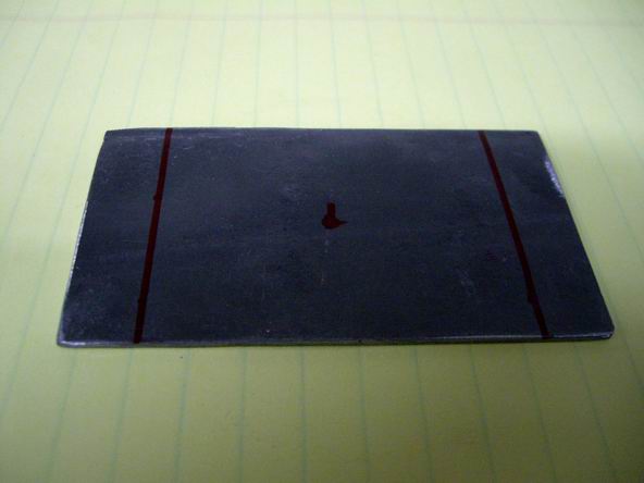
A little work on the tunnel also.
Made a template from paper and transferred to metal for the driver side rear.
Attached image(s)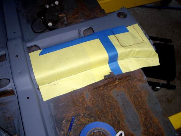
Posted by: Jeff Hail Nov 11 2007, 11:11 PM
Jeff, I have been reading your thread as you go along and I only have one question. Can I have your car when you are done???
No!
Attached image(s)
Posted by: thesey914 Nov 12 2007, 06:38 AM
Subscribed -I love metalwork threads
Posted by: tdgray Nov 12 2007, 10:20 AM
Absolutley incredible Jeff... you have the talent I only wish I could have.
Very nice INDEED !
Posted by: flippa Nov 12 2007, 11:05 AM
Jeff, you are the man!!!!!
I am just beginning my project. Thanks for taking the time to post all this great work. You don't even know how helpful this has been and how much time & aggravation you are saving me.
Keep the great work & education coming.
Thanks
Posted by: restore2seater Nov 12 2007, 07:06 PM
Jeff,
Have you ever used http://www.picklex20.com/ before?
If you have what's your opinion of it?
The reason I'm asking is, when repairing several small areas on one or more panels rather than mixing up a small amount of epoxy primer and spraying the bare metal a spot at a time you could use this to protect the metal until you have a large enough area to mix up one batch of epoxy primer to cover all the small areas.
Posted by: Jeff Hail Nov 12 2007, 08:14 PM
Jeff,
Have you ever used http://www.picklex20.com/ before?
If you have what's your opinion of it?
The reason I'm asking is, when repairing several small areas on one or more panels rather than mixing up a small amount of epoxy primer and spraying the bare metal a spot at a time you could use this to protect the metal until you have a large enough area to mix up one batch of epoxy primer to cover all the small areas.
Never used the product. I do not think the tradename actually refers to Pickling though.
Pickling is a process used to remove mill scale during the manufacturing.
Mechanical removal and then a solution called Pickel liquor which is usually hydrochloric acid or nitric acid. Different types of steel (carbon, stainless etc) use different process's and chemicals.
I do not like mixing small quanities of epoxy primer either. The primer and activator are expensive. It takes me longer to clean the spray gun than it does to apply. If I have to mix up some EP I try to find other things that need priming too like the dog, the neighbors kid (kidding). I will use EP on anything I take down to bare steel. It has better adhesion qualities than surfacers do. Super sticky and holds up better than standard catalyzed primers. Everyone has an opinion as to what is best. EP works for me.
Actually if I have a small spot I will use some etching primer if it's temporary. I will sometimes let bare metal sit knowing I will be back in a day or a few to finish the area. If it is going to be a long period I will try to throw some cheap primer on even if it means sanding it down at a later time.
Posted by: restore2seater Nov 12 2007, 11:10 PM
I was watching an episode of Trucks (Spike TV) this weekend and they mentioned it as a way to seal the bare metal to prevent flash rust. First time I had heard of it.
I have done a few searches on a couple forums and really haven't read anything negative. The people who have used it commented that it works.
I might give it a try when I start doing body work on my teener.
Posted by: Jeff Hail Nov 17 2007, 10:23 PM
Still waiting on tube for the tunnel. I hate waiting on parts!
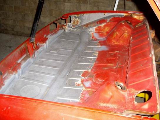
Did some finish work in the trunk. Welded up some pin holes from the floor replacement. 100 pounds of StarBlast just sitting, might as well strip some paint!
Media blasted the rear trunk, removed some scale at the taillight pockets and wheelhouses. A little feather edging. Now it's about 6 o'clock and the sun is down.
A little fog is coming in tonight. Moisture and cold air is not what I need right now. The media blasting removed the zinc coating on the new rear floor. I need to get a coating on this now.
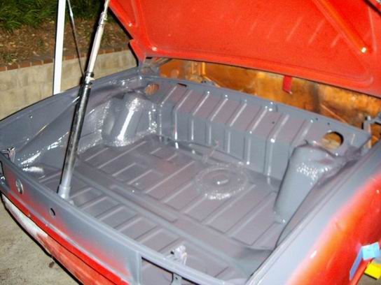
Epoxy primed the rear compartment in the dark with a couple of floodlights so I can see. Finished the primer and the temperature dropped to about 58 degree's. Epoxy Primer won’t kick if it's to cold.
With two heat lamps I created the "Worlds Largest Easy Bake Oven". It's a toasty 85 degree's inside the trunk. Enough to cure the Epoxy primer.
Attached image(s)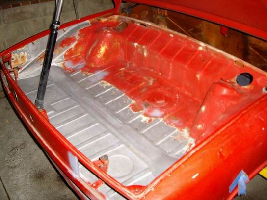
Posted by: Jeff Hail Nov 20 2007, 12:11 AM
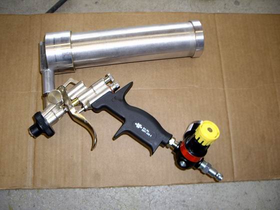
A little more on corrosion protection and applicators.
http://www.914world.com/bbs2/index.php?showtopic=78326
In case anyone wonders I am not a salesman for Wurth Products. I use them because they are superior to most of what I have found available on the market today. Start with the best and the finished product will speak for itself.
Posted by: Twise Nov 20 2007, 04:35 PM
A little more on corrosion protection and applicators.
http://www.914world.com/bbs2/index.php?showtopic=78326
In case anyone wonders I am not a salesman for Wurth Products. I use them because they are superior to most of what I have found available on the market today. Start with the best and the finished product will speak for itself.
I second that...
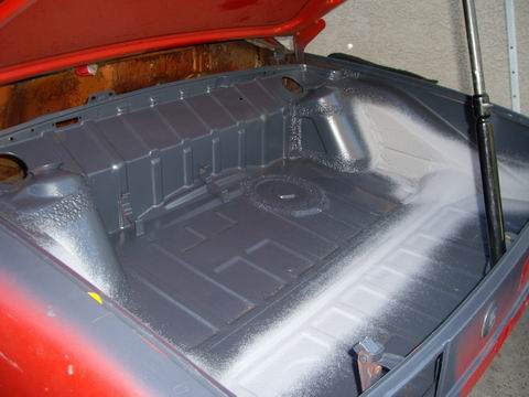
Posted by: Jeff Hail Nov 24 2007, 09:26 PM
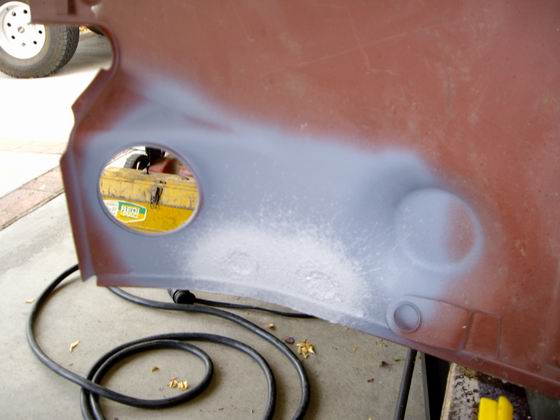
Sprayed the Wurth Seam Sealer in the trunk. Finally looks like a trunk again.
This will all get get covered in color later.
Attached image(s)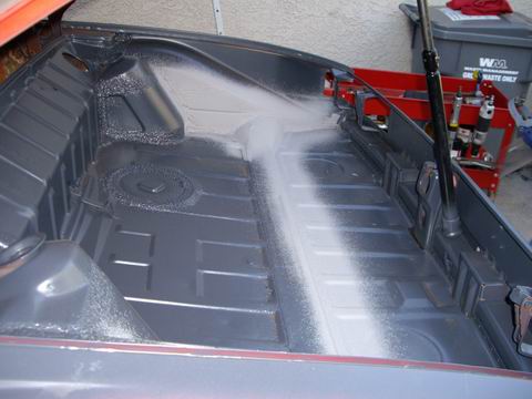
Posted by: Jeff Hail Nov 24 2007, 09:32 PM
Did some more access work for the right rear long replacement. This piece is a bitch to install the entire part. Would be easier to section it behind the suspension console. The high road taken.
I had to cut a window at the trunk bulkhead. No way to get the whole piece in without the cut because it installs from below. I also media blasted the wheelhouse
and bulkhead joint. This area is really tight to weld in so better it as "clean" as I can get it.
Attached image(s)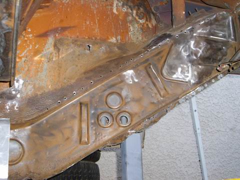
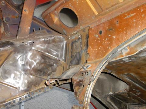
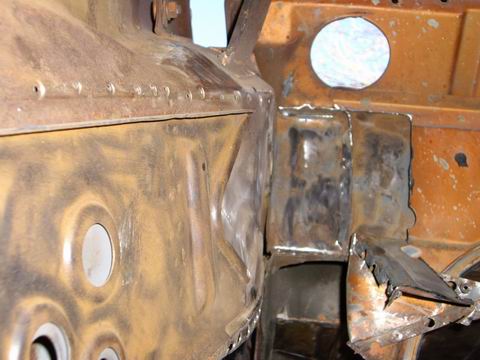
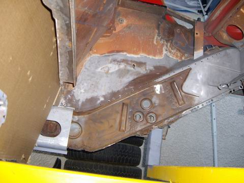
Posted by: Jeff Hail Nov 24 2007, 09:39 PM
As you can see the rear long junction at the bulkhead is really confined behind the first wall. It was gas welded at the factory behind the first bulkhead wall. No access for factory resistance welding. This is a significant connection so I want full access to weld all 3 sides. I used a worn cut off disc to get access ( 2 inches of disc) for the vertical cut.
The last pic is before the prep work (ugly)
Attached image(s)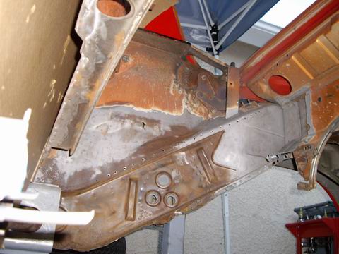
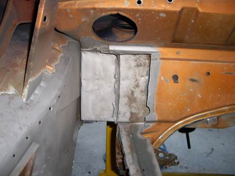
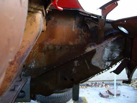
Posted by: Jeff Hail Nov 24 2007, 09:50 PM
Applied some Metal Ready for conversion coating. This way once I install the rear long it will have some corrosion resistance inside the panel. These will get cavity waxed at completion after epoxy primer.
I am going to section the lower wheelhouse. You can tell from the battery tray area down the rust has perforated the panel just behind the firewall. This was planned so when I install the inner rear long I will not weld it to the wheelhouse.
Not even the media blasting would remove the rust. Pitted badly.
I do not want to cut both the wheelhouse and inner long at the same time because the entire right 1/4 of the car is supported right now. I will join the rear inner long to the mid long and weld at the trunk bulhead. This way I have still retain full support during structural repairs.
Once I cut the wheelhouse section I can coat the entire inner long from the wheelwell side with epoxy primer (except the flanges) and it will have superior protection.
Attached image(s)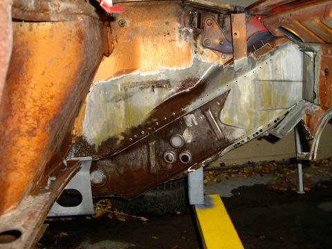
Posted by: Twystd1 Nov 24 2007, 10:34 PM
Jeff,
Rumor has it that you did all of the above work while cooking a turkey, watching a football game, solving a Rubics cube, winning 3 games of online poker and solved the Aids crisis in Rhodesia.
How the hell do you do that....???????? LOL....
Jeff, This is simply great stuff that you are doing. Like many others. I am in awe of what you do.
By the way... Joe Sharp is having a couple of get togethers in Huntington Beach on the first and the seventh of December. Ya wanna come down and meet the 914 peeps...?????
You would be a most welcome guest. And I am bringing enough coffee for both of us..... And a backup pack of smokes....
By the way.... Ya know anyone that has a spare set of 15 X6 Fuchs for cheap??? (not deep ones)
I need them to swap for a set of 7s and 8s.
Cheers and keep it going bro.. This is so much fun to see this work in progress.
If ya need me up there to help ya... Just PM me. I'm down to help if needed.
Clayton
Posted by: Jeff Hail Nov 24 2007, 10:53 PM
Jeff,
Rumor has it that you did all of the above work while cooking a turkey, watching a football game, solving a Rubics cube, winning 3 games of online poker and solved the Aids crisis in Rhodesia.
How the hell do you do that....???????? LOL....
Jeff, This is simply great stuff that you are doing. Like many others. I am in awe of what you do.
By the way... Joe Sharp is having a couple of get togethers in Huntington Beach on the first and the seventh of December. Ya wanna come down and meet the 914 peeps...?????
You would be a most welcome guest. And I am bringing enough coffee for both of us..... And a backup pack of smokes....
By the way.... Ya know anyone that has a spare set of 15 X6 Fuchs for cheap??? (not deep ones)
I need them to swap for a set of 7s and 8s.
Cheers and keep it going bro.. This is so much fun to see this work in progress.
If ya need me up there to help ya... Just PM me. I'm down to help if needed.
Clayton
Well the turkey has metal shaving's in it. Good source of iron though!
The Rubiks Cube wasn't a challenge and I used it as a decoration in my fish tank years ago. Football? Nope....I like sports that use a stick. My best friends son was just voted National Rookie of the Year in baseball. Proud pappa! No gambling except for an occassional lottery ticket. Porsche's cost money you know? Hunger is cured with coffee, lots of strong black coffee.
I have only been working on the car on the weekends. 10 hours or so a week. I want summer back.
Won't be able to make the 1st or the 7th. Thanks for the invite.
Wheels? I need a set of Rota's in 7 and 9 for my car. Something tells me I am going wih glass 1/4 panels so rear 10's might be in the lineup. If I can make my buddy part with an original set of RSR 9's and 11's I might shoehorn them in.
Posted by: Eric_Shea Nov 24 2007, 10:55 PM
How about me? Can I have it?


Posted by: Jeff Hail Nov 24 2007, 11:00 PM
How about me? Can I have it?
Eric will have the pleasure of rebuilding my calipers soon. At least you get a piece of the car!
Posted by: Eric_Shea Nov 24 2007, 11:03 PM
Yeah but... I have to give them back!
Keep up the good work bud.
Do you like to ski (and weld)?
Posted by: Jeff Hail Nov 24 2007, 11:19 PM
Yeah but... I have to give them back!
Keep up the good work bud.
Do you like to ski (and weld)?
I used to ski and race giant slalom 20 years ago as a young man. I became bored with skiing. Snowboarders slowed everyone down.
 Last time I raced was at Ajax/ Aspen a long time ago.
Welding is fun. I get to burn things on purpose.
Posted by: Jeff Hail Nov 25 2007, 08:24 PM
Spent about 3 hours today fitting the new rear rail. I had a bit of re-work to get the dimensions right. It's not bad, just takes some time to fit.
Anyway the part whether new of aftermarket has to be fit and trimmed.
Any sheetmetal part that is not bolt on and is supplied as cut to fit is going to take some work.
The trick on the rear rail (AA Part) is to fit it to the front inner long first. From there you will get the correct pitch (angle) leading to the trunk bulkhead. This took some fiddling and trimming. I cut off about 1/4 inch at the rear and obtained the correct angle for a flush fit. I then had to fishmouth the front inner long to get some "play" in the adjustment. ( I hate bending a newly installed inner long)
The pitch of the rear rail is 34 degree's as measured from the driver side. I am at 31 now. I need to drop the front ever so slightly (1/4 inch). This is imperitive for suspension geometry.
Then I trimmed another 1/2 inch at the front long connection to get a verticle flush/ butt connection. (I still have to do some fine tuning with a grinder)
This will need to be sleeved (double walled) as it is a highly stressed joint)
I was hoping as I timmed back the new rear rail I could lap weld the joint but the convolutions did not allow that. No worry. I will modify the aftermarket part to incorporate the factory type reinforcement.
If you look at the second picture you will see the top of the panel connection is really close. The bottom is way off. This is a manufacturing issue. I will adjust and weld the top first, then splay the rail (box) open some more to fit the bottom.
As the fit process came to conclusion I held the new panel in with a C-clamp and cleco's. This is only a rough fit and not tack welded until I complete the adjustments by lowering rear rail by 1/4 of an inch at the front long connection.
Attached image(s)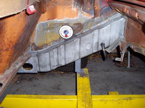
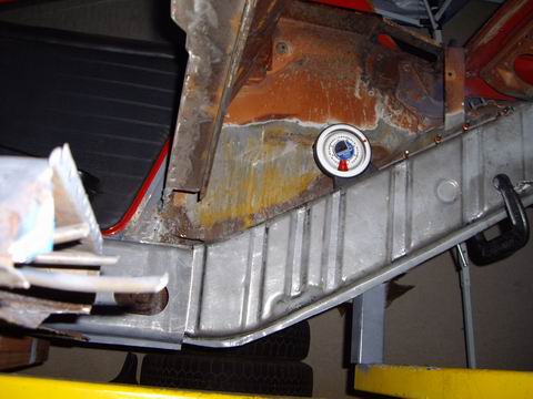
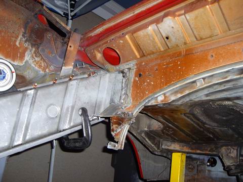
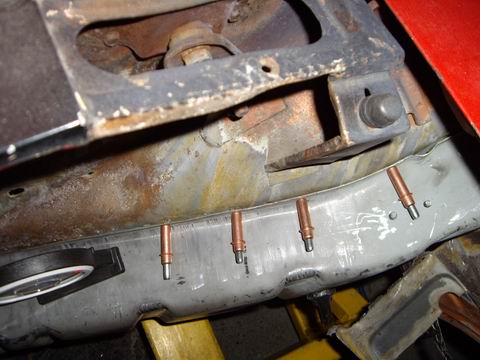
Posted by: Jeff Hail Nov 25 2007, 08:31 PM
For this installation a protractor or (inclination gauge) is worth it's weight in gold ($18). I can take fast comparitive measurements from side to side.
I have not been able to find specifications in print for this area from Celette, Mitchell or even the factory so it pays to have a tool for comparison. By making some fixtures for the control points prior this will alleviate any problems later.
I also have an aftermarket suspension console to use for fit purposes. This will
provide fit and additional comparison measurements for correct suspension geometry.
Attached image(s)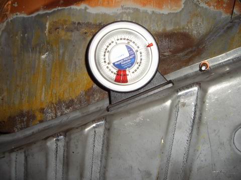
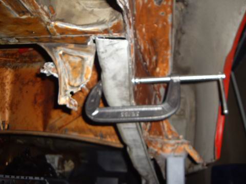
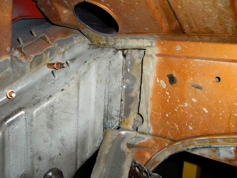
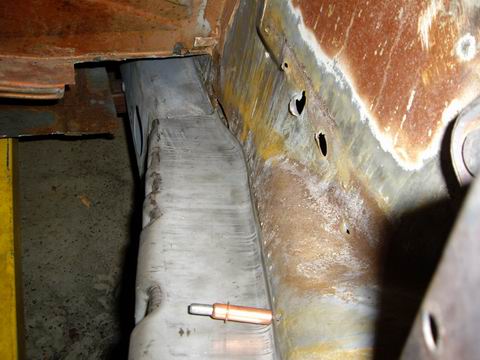
Posted by: Jeff Hail Nov 25 2007, 08:52 PM
Clecos are easier to work with than self-tapping screw's. They plug in and out. Cleco's have enough "slop" in them to allow slight adjustment if only a few are used. The more are used the more rigid the mock up. Once I get the position
of the part where it needs to be I will tack it with the MIG.
Attached image(s)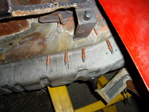
Posted by: Jeff Hail Nov 25 2007, 09:41 PM
The original outer wheelhouse has a reinforcement (double wall) welded to the inside. It has a ledge that locates the inner rail's top flange (highlighted). This was my reference point to measure the pitch of the original rail design along with the opposite left rail.
Nothing better than a factory template! Once I tack the rail at the trunk bulhead and top of the rail the lower flange will be a cinch to tweak as I go.
I wish I had more daylight. I want my summer hours back!
Attached image(s)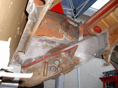
Posted by: Jeff Hail Nov 25 2007, 10:21 PM
Interesting Vitaloni's found in the box of extra's. I have not seen these since 1983. They are in perfect shape. No scratches on the glass or housings. Rubber in good perfect condition. Not California's, not Baby Turbos, not Classics.........That blue tinted glass is so 80's. They are actually pn# a right and left (not universal) pair.
They are marked Vitaloni Bravo III's which were standard on the the Lancia Zegato and Alfa Romeo's.
What the hell were these doing on a German car?
Attached image(s)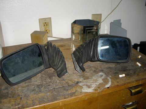
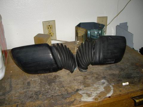
Posted by: Aaron Cox Nov 26 2007, 09:25 PM
wow jeff.
wow. I just read your whole thread, after clayton told me about his visit to su casa.
Quite the craftsman!!! Keep up the good work buddy!
Aaron
Posted by: Jeff Hail Dec 2 2007, 08:04 PM
Busy week and weekend. No time to play. Work, birthdays, meetings etc.
Finished fitting the rear frame rail and punched the flange holes. Some minor adjustments to the rail with a grinder to improve the fit and butt joints.
Used some stock to square up the joints and clamped everything in place.
Not 100% happy with the fit. The AA part dimensionally has some issues.
The arc of the rail itself is not right and will have to be adjusted once I make some tacks. Then I can twist it into place. These things come up even with new oem parts so it just part of the process. That's why they call it work.
Attached image(s)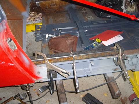
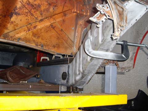
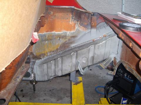
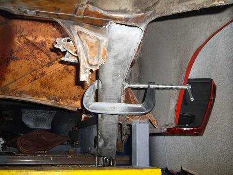
Posted by: Jeff Hail Dec 2 2007, 08:23 PM
More stock to square the inner long to the rear rail and clamp in place. You will notice the rectangle inside the long. Just some scrap that I can clamp in place to keep the panels straight and tight. Once you start tack welding metal tends to draw together. This just helps keep things in place so things don't go sideways.
Another tip is to keep the welder close enough that the controls are in arms reach.
One thing about welding on the 914 is you have the longs and rails which are about 17 gauge oem and 18 gauge non oem steel. The wheelhouse and trunk bulkhead are the same. The joint at the shock tower is close to 15 gauge. A few small heat adjustments are necessary on the fly.
Old 914 sheetmetal even when really clean can still have some issues. I have learned on many a Porsche that the best steel (Krupp and Thyssen) was not utilized and can be "dirty". During the manufacturing process the alloy can vary and this sometimes means more or less sulpher. Some parts such as the longs and rails are an early form of HSLA steel. (High strength low alloy) which mean's it is harder and stiffer. If you have ever tried welding a new steel panel to old steel on a 914 you know what I mean. A great weld, then a little popping and sputter here, blow a hole there. Its all part of the game. Prep metal and get it as clean as possible for welding.
Attached image(s)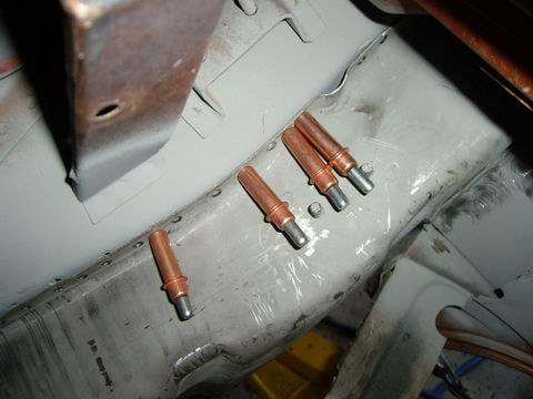
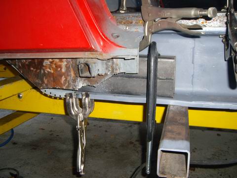
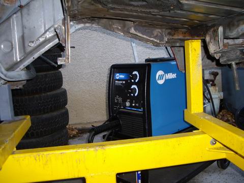
Posted by: Jeff Hail Dec 2 2007, 08:38 PM
Enough talk. Time to burn some metal.
Tacked the rear at the bulhead then tacked the front at the bottom of the long.
Re-check fit and then lay on the heat. I like to seam weld thin sheetmetal in 1/2 to 1 inch burst's. This way I do not oveheat and warp the area but still get enough heat for proper penetration.
You will notice the top of the mid inner long is not tacked to the rear rail. This is where I have a little twist in the rail that needs some fitment. With the rear and lower tacked in I can get some leverage on the top and fit the butt joints better.
The outer wheelhouse is getting a section so no plug welds were made except for where the Cleco's were pinned.
Attached image(s)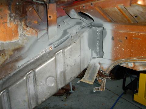
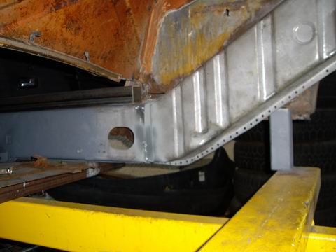
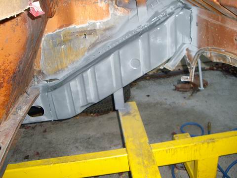
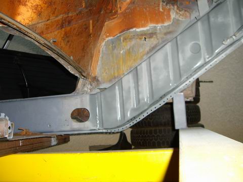
Posted by: Jeff Hail Dec 2 2007, 09:11 PM
Crud!!!!!went to make another post and the site went dead for a minute. Lets try again.
The area's highlighted in yellow have no welds, plugs or tacks.
Area's in red have been tacked, seam welded and plugged.
I now have structural integrity again (sort of). The top of the rail at the top of the long is free. I need some adjustment room when I install the wheelhouse section
The entire right qtr panel, wheelhouse at the long / firewall junction have been held together with one single tack weld at the inside of the door jamb/ dogleg.
I could not perform these operations on jackstands. The door bars kept the door gaps open and everything rigid on the upper body. The rack below kept everything level.
Attached image(s)
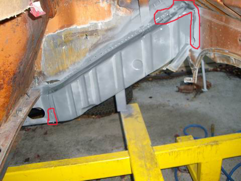
Posted by: Jeff Hail Dec 2 2007, 09:24 PM
One single weld holding the qtr panel/ dogleg this whole time. (highlighted)
Now that structural integrity is back I will move to the wheelhouse. Another piece that will require fitting. It is easier to go back to something that was partially completed then going backwards and doing something over if it doesn't come out right. Take your time and be patient.
Couple of things. Most of the prior welding on the longs was done at about 70-80 degree's. The rail was done at 48 degree's. Metal cools much faster and draws together quicker. This is noticable and it will affect gaps. That single weld will save me hours of future fitting and headaches.
The other one is the mid long and rail joint is butt welded. This will get a double wall sleeve just like the factory design. Do not butt weld a rocker without a sleeve. This is for any car with a structural roof or not. It is one of those things you do not ask why, just do it.
Attached image(s)
Posted by: Twystd1 Dec 3 2007, 12:20 AM
Jeff, explain that further. As I think I know what you mean. But I want to be exactly clear on what you are saying.. (pics would be good for this nut head)
Ohh.. I found a Cellete bench with both the 911 and the 914 jigs in Buena Park.. In a Porsche mechanics garage.... No shit....
Now how do I tell the guy I need it for my bros...????
And where the hell do I put it on the assumption he will sell it to me...?????
Ya got any ideas...?????
Oh... Before I forget... I LOVE THIS SHIT.......!!!!!!!!!!!!!!!
Carry on sir.
Clayton
Posted by: Jeff Hail Dec 3 2007, 01:37 AM
Jeff, explain that further. As I think I know what you mean. But I want to be exactly clear on what you are saying.. (pics would be good for this nut head)
Ohh.. I found a Cellete bench with both the 911 and the 914 jigs in Buena Park.. In a Porsche mechanics garage.... No shit....
Now how do I tell the guy I need it for my bros...????
And where the hell do I put it on the assumption he will sell it to me...?????
Ya got any ideas...?????
Oh... Before I forget... I LOVE THIS SHIT.......!!!!!!!!!!!!!!!
Carry on sir.
Clayton
It's pretty much a re-hash of Page 4 on this thread.
Mid long =longitudinal under the door.
Rear long =rear frame rail
This is nuts.
They should call the bolt on rocker the rocker molding.
Then the outer rocker would be the piece the sills and triangles weld to.
The inner long should really be called the inner rocker panel.
Every other manufacturer uses this terminolgy.
Why can't we? Organized chaos theory interpretation by Porsche?
In the collision repair industry if you refer to an inner rocker as a longitudinal
you are going to get that "what the f up" look.
Celette? How much? 20K minimum for a 20 year old bench with full set of obsolete fixtures is my guess and that is low if the guy is not using it. Maybe he moved in and the old tenant left it there (ha, ha). Even used they are spendy.
The cheapest bench they sell are like the one below that the 356 is on. The other one that the 911 sits on is quite a few duckets more. A bare Celette bench with nothing, no fixtures, no rocker clamps/ perch's- nothing is about 16k today for a new roller. For restoration work you do not need towers (for pulling). A good Port-A Power set is cheap for jacking stuff around.
Then if you do buy a dedicated bench how are you going to get home? Your red toy isnt going to do it.
Attached image(s)
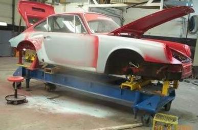
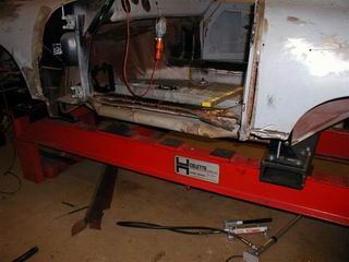
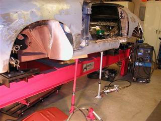
Posted by: Jeff Hail Dec 3 2007, 02:20 AM
[quote name='Jeff Hail' date='Dec 2 2007, 11:37 PM' post='973233']
[quote name='Twystd1' post='973215' date='Dec 2 2007, 10:20 PM']
[quote]The other one is the mid long and rail joint is butt welded. This will get a double wall sleeve just like the factory design. Do not butt weld a rocker without a sleeve. This is for any car with a structural roof or not. It is one of those things you do not ask why, just do it.[/quote]
Jeff, explain that further. As I think I know what you mean. But I want to be exactly clear on what you are saying.. (pics would be good for this nut head)
Clayton,
Did I loose you along the way?
The rear long will be butt welded and sleeved just like the inner long section that is already done. Same procedure except about 16 inches farther back.
I included a photo of the old piece to show the double wall. Only difference is instead of a single wall I will double the layer at the butt weld on 3 sides of the box.
Clayton? Clayton?
Attached image(s)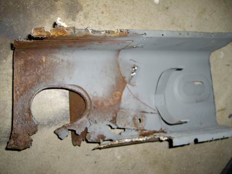

Posted by: Sarastro Dec 3 2007, 12:59 PM
I don't know why I find your work so fascinating. Maybe I'm someone who likes to see things done the way they should be (and not so often are). As a long time 914 owner (since 1973) I really appreciate what you are able to do to conserve these cars.
I am not a mechanic and I haven't done any welding since High School autoshop in the 60's but after watching you work, I feel like buying a Miller and joining metal.
Posted by: Jeff Hail Dec 8 2007, 04:50 PM
Sheet happens!
Ever wonder how much force is on a door bar when welding? Ever wonder how much energy is moving when metal draws together? Ever wonder how much a 914 shrinks when welding in the long area?
My passenger side door opening brace snapped. I am underneath and hear this BANG! Scared the crap of me and hit my head. The turnbuckle gave way. It was only 3/8 but it was forged. I have used them on another 914 and also a 911. They lived a good life.
Attached image(s)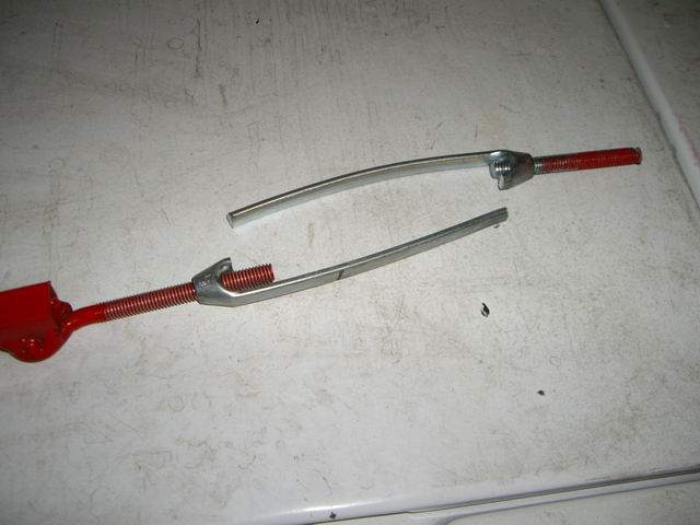
Posted by: Jeff Hail Dec 8 2007, 04:52 PM
Built another set of door braces. This time I used 5/8 inch cold rolled solid rod and 1/2 inch rod ends. Of course they have to look good too (waiting on paint to dry).
Attached image(s)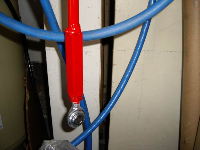
Posted by: Twystd1 Dec 9 2007, 12:59 AM
Hi Jeff,
Kinda been 2 busy to respond lately.
The follow up pics and explanation was PURRRFECT.
That exactly what I needed to show someone. I am most grateful for the answers you provided.
Now where the hell are we gunna put the Cellete bench??????
I came up with a number he liked. (Stupid Cheap)
Now I just need a Christmas ferry to show up and make it real.
Jeff... The bench is in this guys HOME Garage.
WITH all the 914 and 911 jigs. It isn't the small bench. It's the medium size one for 9elebens on down. He wants it gone by February...
HHHmmmm... Can we put a room addition on your house by then...????
Cheers and maximum thanks bro.
Clayton
Posted by: Jeff Hail Dec 9 2007, 05:54 PM
Clayton,
I will pass on the Celette. No room! My avatar signature says it all.
Thanks buddy.
Posted by: Jeff Hail Dec 9 2007, 06:28 PM
HOW TO BUILD A CLUTCH TUBE
Choose your steel wisely. Once it's in the last thing you need is a problem.
The original OEM tube is metric and some weird stuff. I thought at first it may be stainless. Stainless does rust by the way. Nope not stainless. Then maybe something else. Finally ended up taking a sample to friend who is a machinist. Pretty sure it's chromemoly. Who knows what alloy though?
Have you ever priced SAE tube versus Metric? Same alloy's although Metric is about 3-5 times more. Organized crime!
The OEM clutch tube is:
.470 OD
.040 Wall
McMaster-Carr
4130 Chromemoly Aircraft Grade Structural tubing. Inside has to be seamless DOM or honed. You do not want a weld burr fraying your cable. Even with the a cable liner a burr will chew it up.
.438 OD
.065 Wall
Thicker wall and a hair smaller OD diameter (0.032). I will be using a heavy duty clutch cable and fit is loose inside the tube. Good to go.
First to make the flare. It's really not a flare. It's more of a fishmouth- flare.
Chromemoly is fairly tough. I do not have a flaring tool this large. I also do not want to flare it cold because I think it will split the opening. 0.065 wall tube is thick.
Crank up the fire stick and get the end cherry red all the way around........
In the background you will see a blue punch laying on the bench. It has a perfect taper mid way up the shank that match's the original tube's contour. After heating the tube until it glows I slide the punch into the tube and let the taper do the work with the assistance of a 5lb hammer. I did not have to beat it to death. Just work the punch in gently. Keep it under heat (not enough to melt) and drive the punch in little deeper. Took about 5 minutes.
Attached image(s)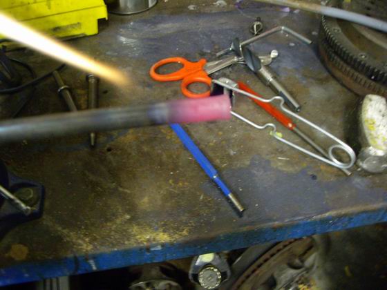
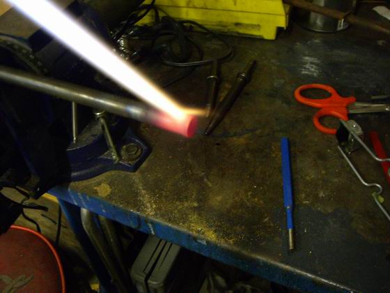
Posted by: Jeff Hail Dec 9 2007, 06:35 PM
HOW TO BUILD A CLUTCH TUBE -Cont'd
Once I was happy with the contour I smoothed the entrance of the flare to remove any burrs. I first used a small round stone (for porting) on a shank to round the mouth beyond what the punch would do. Then I took a smaller stone and rounded the opening a little more. A dab of valve grinding compound provides a final finish.
The old tube (right) and the new one (left)
Attached image(s)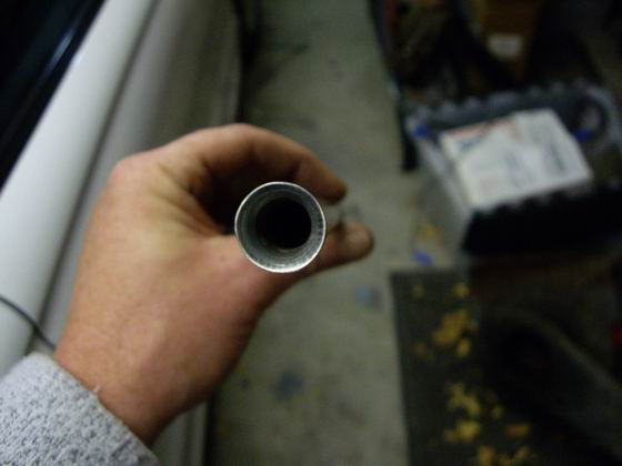
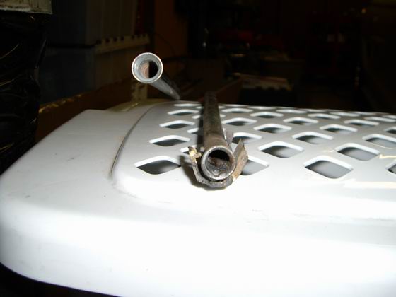
Posted by: Jeff Hail Dec 9 2007, 07:01 PM
HOW TO BUILD A CLUTCH TUBE -Cont'd
Too cold to do any welding outside today (yes this is SoCal) It's 40 degrees.
Inside a garage with torch's is a great idea!
I have to bend the tube. It also needs to match the original arc so I have correct cable length on both ends.
I little trick I learned in the aircraft industry (cheating). If you put a tube in a vise you don't want to crush the tube use a collar or sleeve around the tube. The tube you are working with can remain free or if you tighten it up enough it can secure the tube without crushing it. It also will not leave tool marks or sharp edges.
With the new tube in the collar I heated the tube again until it has a soft red glow. (not cherry) I keep the heat moving in the span of the arc I want to create. Once the tube is warmed up I apply presure as I walk the tube thru the collar at about 3/4 inch intervals to create the arc. With each step thru the collar a light tug makes a nice round bend. The actual radius of the bend is large so a tubing bender didnt make sense.
This has to be done slowly and gently otherwise the tube will kink or collapse and end up oval shape pinching the cable.
Attached image(s)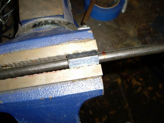
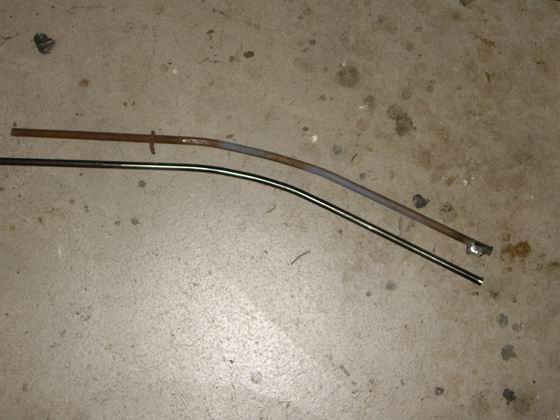
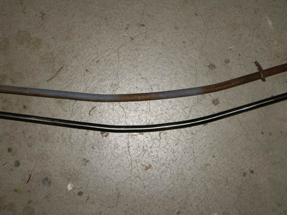
Posted by: Jeff Hail Dec 9 2007, 07:04 PM
HOW TO BUILD A CLUTCH TUBE -Cont'd
Last picture is the cable (engine side) in the opposite end of the tube. Cable and liner travel freely. Once installed in the car I will size the rear end of the tube to 32-34mm protrusion at the lower firewall.
Whole process took about twenty minutes.
Attached image(s)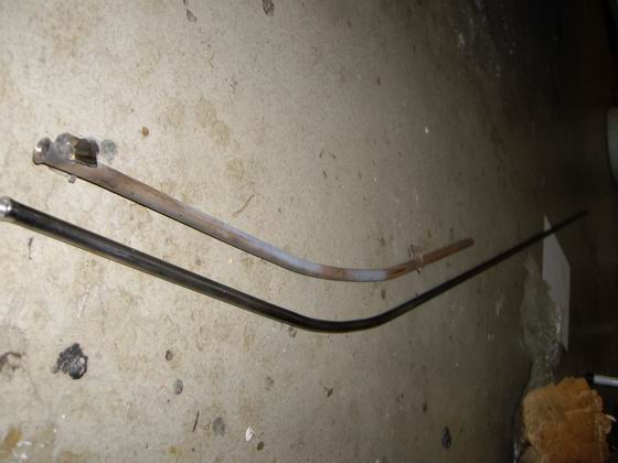
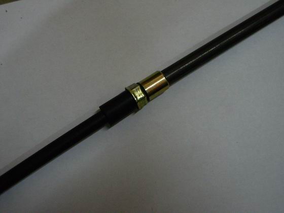
Posted by: Jeff Hail Dec 30 2007, 10:13 PM
Holidays, birthdays, anniversaries, end of the year, and business are not conducive to project progress. They each have a place though. Throw in a little 10 day vacation for myself and back to work.
Split the tunnel open at the shifter to get the old conduits out. Good bye to that rusty rat's nest of tubes out. The original throttle cable conduit was rusted and broken midway at the support. This was like dental work as the confines were tight and I really didn’t want to butterfly the entire tunnel open.
Time and patience make the end result worthwhile.
First photo shows the cut. The shifter opening is reinforced. It is doubled layered and has the three nutplates wekled on the underside. First peel the tunnel back and then cut the right front of the reinforcement out.
Second photo all the old conduits are out.
Third photo........by the way the site just burped and I had to re-post again.
Third photo I have welded the shifter reinforcement back in. After grinding I couldnt even find the seam.
Attached image(s)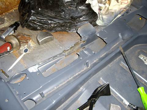
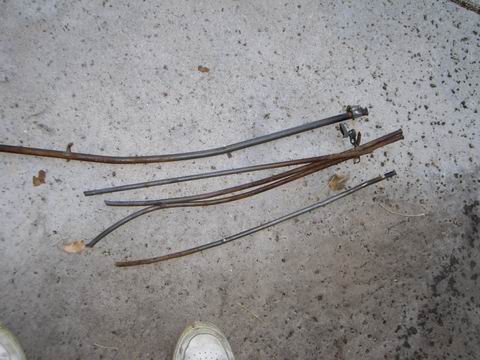
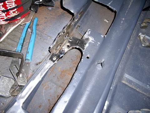
Posted by: Jeff Hail Dec 30 2007, 10:31 PM
Inside the tunnel running on the left side is a shield that the throttle cable conduit runs through along side the shifter. To remove the old conduit I had to drill the spot welds only at the bottom to get the tube out. It is brazed at the rear and a twist of the tube with pliers breaks the braze with ease.
First and second photo shows the red punches and vise grips holding the shield in alignment for welding. I stuck a piece of tubing in the cavity to make sure I have enough clearance to fit the throttle cable conduit later.
Third photo shows the fabbed conduits sticking out the back of the tunnel. These will get cut to fit once the lower firewall is in place.
Last photo shows the throttle and clutch cable conduits at the front of the tunnel properly spaced. Always take measurements before you swap something as critical as these. The tunnel and conduits do not give second chances once everything is sealed up.
Now that everything is fit I will fab a couple more brackets to locate and secure the conduits permanently inside the tunnel.
Attached image(s)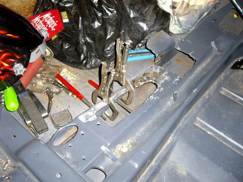
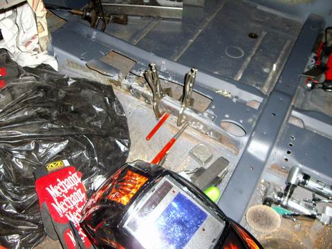
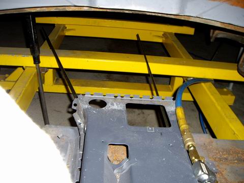
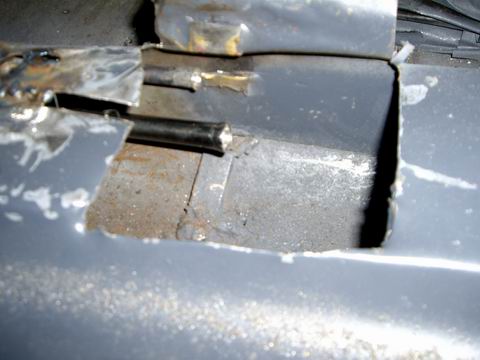
Posted by: Jeff Hail Jan 14 2008, 12:29 AM
Since I havent been getting a lot done on the tub lately I might as well post something of interest. Consider it like "Intermission at the Drive In Movie" without the popcorn.
Porsche Factory Tools, Gauges, Chassis Fixtures.
Since most of these tools are NLA and long gone unless used for other models like the 911 most people have never seen. Some of the manuals have poor pictures of them but most of what you see here will be the first time.
Enjoy!
Starting off with the simple ones:
1) Rear hinge tool
2) Wheel bearing installation tool (love the mallet)
3) Shifter bushing driver (metal dowel)
3-4) Strut alignment gauge
Attached image(s)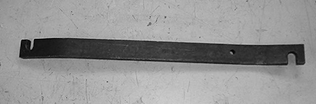
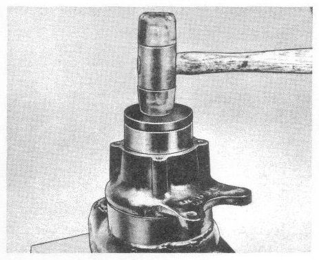
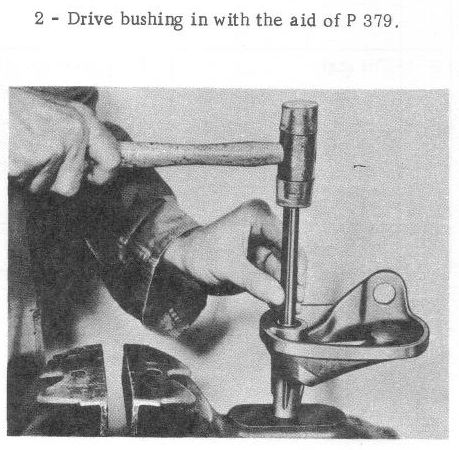
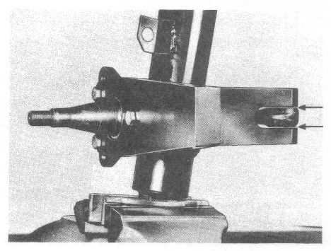
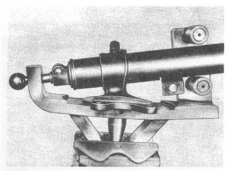
Posted by: Jeff Hail Jan 14 2008, 12:31 AM
5-6) Rear caliper vent clearance gauge (Erics going to make one of these)
Attached image(s)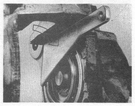
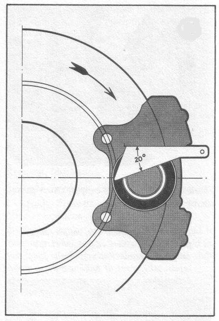
Posted by: Jeff Hail Jan 14 2008, 12:36 AM
And the more complex tools and fixtures for the chassis.
I actually saw this set back in 1981. The front suspension fixture is also used 911's. Today it it considered priceless. To think some shop owners in the 1990's probably ended up throwing them out of scrapping them because they were old and insurance companies were totalling all the late 60's and 70's Porsches because the market was soft. Ugghhhhhhh!!!!
Attached image(s)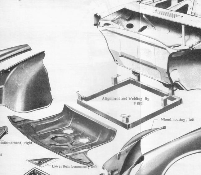
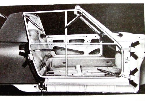
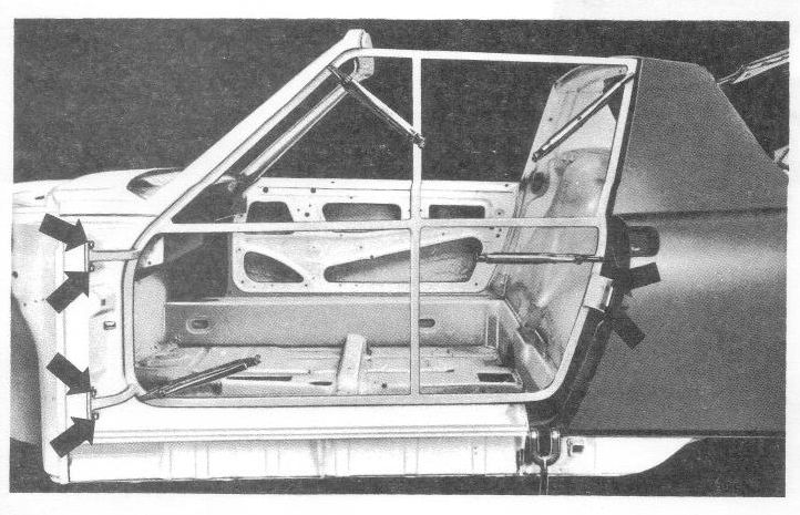
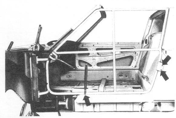
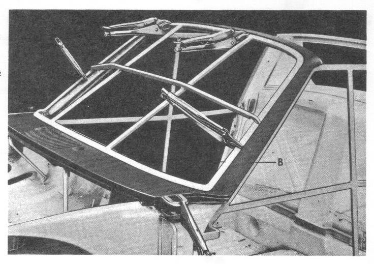
Posted by: Jeff Hail Jan 14 2008, 12:38 AM
Contd
Attached thumbnail(s)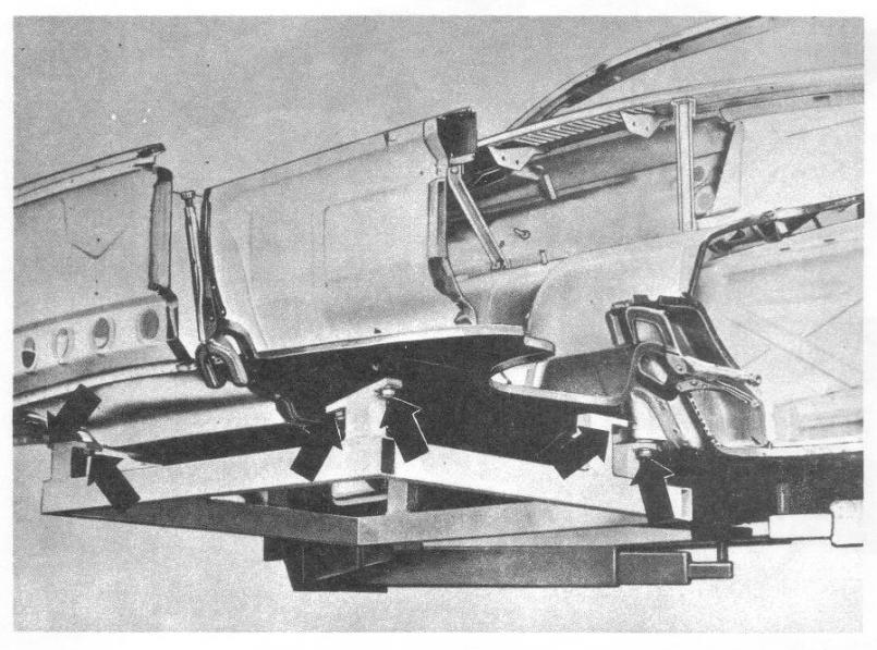
Attached image(s)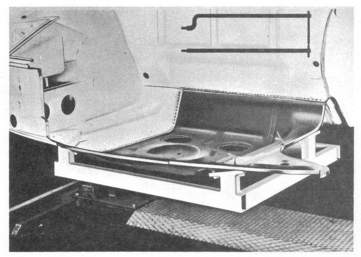
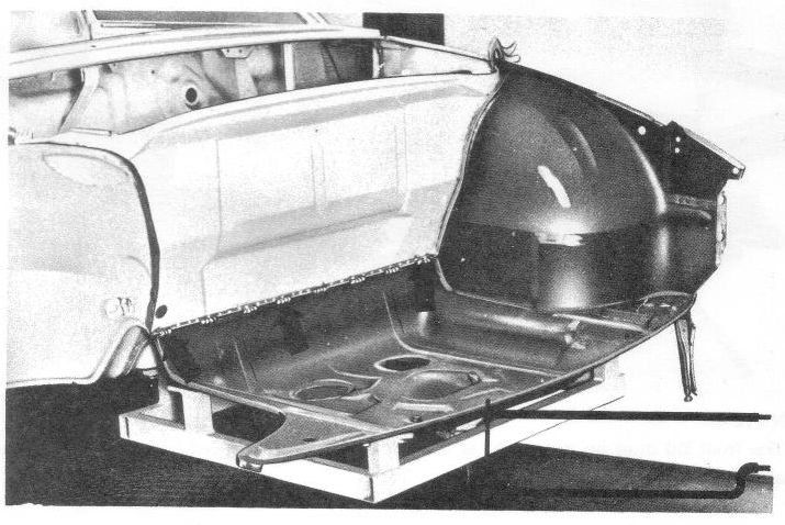
Posted by: Jeff Hail Jan 14 2008, 12:50 AM
Technical documentation:
Porsche new early on the 914 was prone to rust.
1) Dealer Bulletin on Corrosion
2) Detailed schematic of where foam, sealant and undercoating locations were along with grommets and hole plugs.
This document is scary! Every where there is foam we now have rust!
Attached thumbnail(s)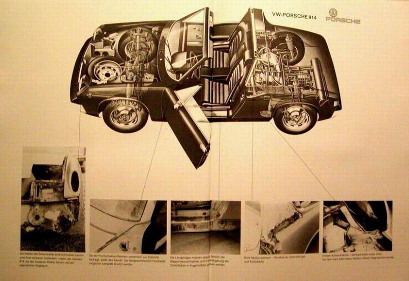
Attached image(s)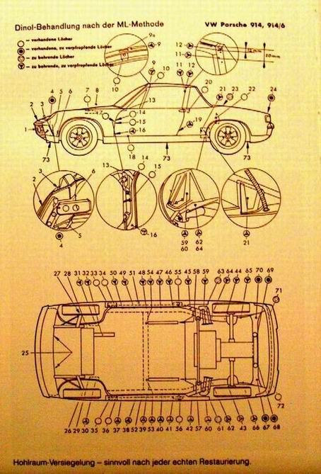
Posted by: Twystd1 Jan 14 2008, 01:05 AM
Jeff,
I am dam glad you posted. As I was considering creating a new post with the byline of "WHERE THE HELL IS HAIL...?????"
And here ya are... !!!! Ya must of heard me.
Jeff, Can ya PM me your phone number? I might be coming up your way next weekend. And hoped I might drop by again and check in with you.
You supply the coffee. I supply the smokes.
You should be shooting video of this build.
Think about it for minute Jeff. We could sell a "HOW TO RE-BUILD A 914 BODY VIDEO" And sell it hand in hand with my soon to be famous and forthcoming, "HOW NOT TO BUILD A TYPE IV ENGINE".
Dude... We could be in the bucks real quick me thinks. I still have to get my video cam repaired, as I was trying to fix the power supply section of my camera. And apparently I did something a bit wrong.
(I thought they plugged into the wall socket... But no.. It takes battery's. Who woulda thunk...????????) (Must be a Chinese thing)
Bottom line.. Good to have ya back.
Cheers,
Clayton
Posted by: Jeff Hail Jan 14 2008, 01:47 AM
Jeff,
I am dam glad you posted. As I was considering creating a new post with the byline of "WHERE THE HELL IS HAIL...?????"
And here ya are... !!!! Ya must of heard me.
Jeff, Can ya PM me your phone number? I might be coming up your way next weekend. And hoped I might drop by again and check in with you.
You supply the coffee. I supply the smokes.
You should be shooting video of this build.
Think about it for minute Jeff. We could sell a "HOW TO RE-BUILD A 914 BODY VIDEO" And sell it hand in hand with my soon to be famous and forthcoming, "HOW NOT TO BUILD A TYPE IV ENGINE".
Dude... We could be in the bucks real quick me thinks. I still have to get my video cam repaired, as I was trying to fix the power supply section of my camera. And apparently I did something a bit wrong.
(I thought they plugged into the wall socket... But no.. It takes battery's. Who woulda thunk...????????) (Must be a Chinese thing)
Bottom line.. Good to have ya back.
Cheers,
Clayton
Clayton! Whats up dude?
Yeah been kind of quiet on the tub lately. Busy at the day job. Damn cold up in these hills. At least for this California boy. 30-40 degree's is too cold for me. I would never make it on the east coast unless I had a heated garage. Today it crept up to a high of 60 and me with an empty cylinder of C02/Argon. I have been picking up a bunch of parts for the build and getting other things done. Foley has my suspension pickups done. Should be here Tuesday or so. All is not idle. Little things have to get done too. When its done its done. No hurry.
Video of the 914 chassis reconstruction? It would be up there with the greatest story ever told. At least as long! And I have the perfect title! "IT'S ONLY MONEY".
Pm sent
Posted by: Jeff Hail Jan 14 2008, 10:21 AM
This is what I am going with for shifting the 915. PMS supplied and they also built the trans mount hoop. Lighweight and stout.
Attached image(s)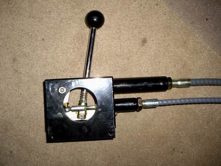
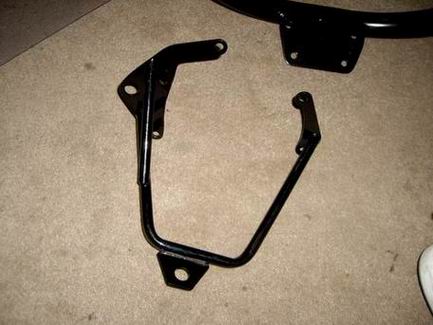

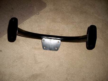
Posted by: Jeff Hail Jan 17 2008, 12:54 AM
The Fedex and UPS guys are beggining to get suspicious. Many large boxes arrived yesterday all at once.
Suspension pickups from Mr. Foley and the Rota's came in.
These are the Rota Fox (Fuchs Repros) in 7-1/2 x 17 and 9x 17. I ordered them unfinished (comes in primer). I will have them powdercoated in mat black on the entire wheel. No shiney stuff on this build!
It's only metal and money. You can't take it with you.
Attached image(s)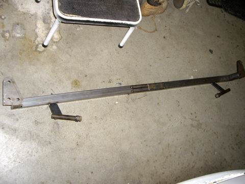
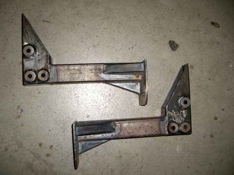
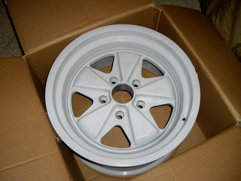
Posted by: tdgray Jan 17 2008, 02:33 PM
Ooooohhh Pretty
Posted by: Jeff Hail Jan 19 2008, 06:16 PM
Kept the Powder Coat and Blaster guy busy for a couple of hours.
Old grungy pedal assembly
and the new and improved model
Why silver? The coater was doing a large job and did it for free. Once they are under the pedal board you won't see much. (RAL Anodized Silver)
Attached image(s)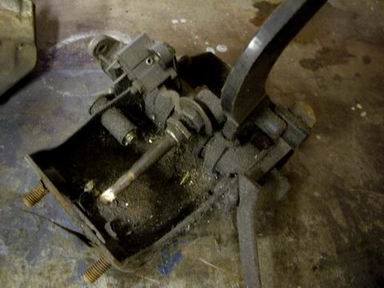
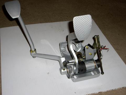
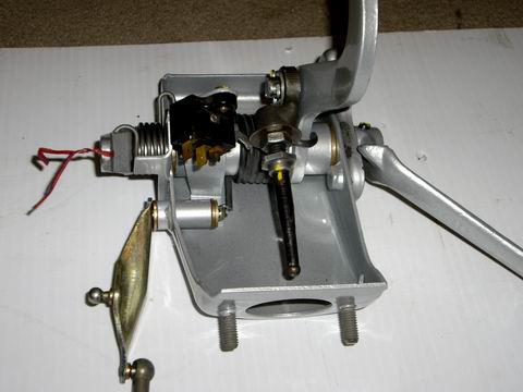
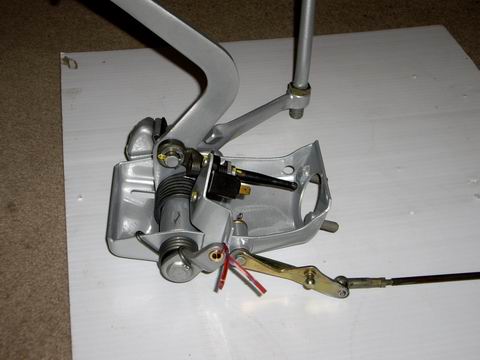
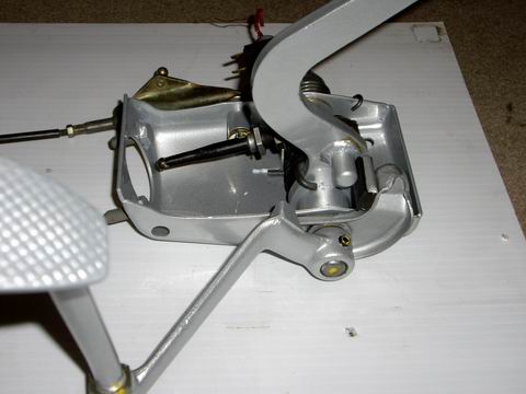
Posted by: Jeff Hail Jan 19 2008, 06:23 PM
Naked trailing arms
Attached image(s)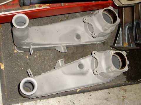
Posted by: Jeff Hail Jan 20 2008, 08:45 PM
A full day to play.
Installed both the new throttle and clutch cable conduits in the tunnel.
The repros I made were pretty accurate. The angle of attack on the front flared ends was perfect.
Welding inside the tunnel is difficult at the same time tense. After all the tacks you just hope you don't burn a hole thru the tubing and end up having to start over.
I didn't get a chance to test fit the cables yet but I think I did not perforate any of the new tubes.
At the front mouth of the clutch tube I welded a sleeve over the tube prior to install. Since the clutch tube has some decent presure on it during usage it needs to be more stout than the throttle cable tube. The sleeve let me get some heat into the remnant of the old bracket still in the tunnel without burning a hole in the tube itself.
Threw some rattle can primer on for now. Still need to grind the welds on the outside of the tunnel to clean it up.
Looks like some rain coming.
Attached image(s)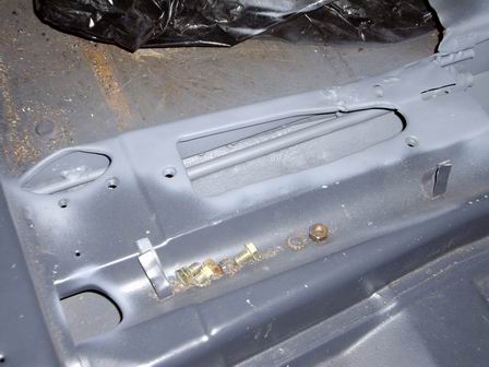
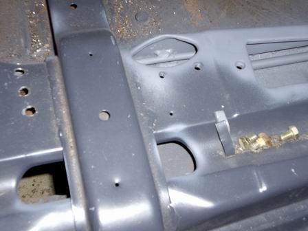
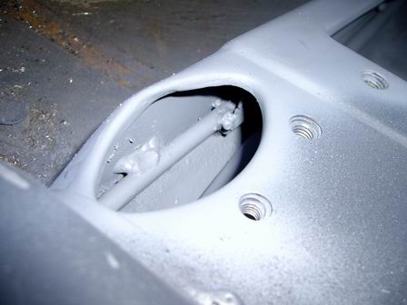
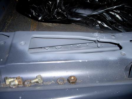
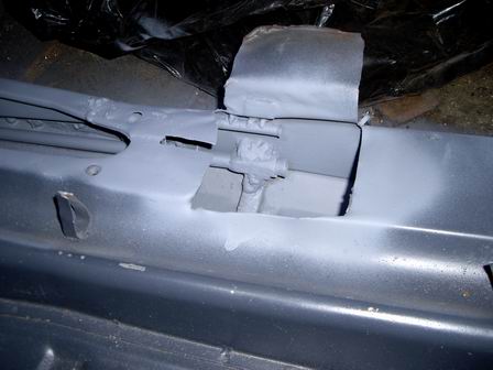
Posted by: Jeff Hail Feb 2 2008, 08:26 PM
Busy few weeks at work. Rain, rain and more rain coming tomorrow.
No time to play..............
Garage time
Boxed the rear trailing arms today.
Attached image(s)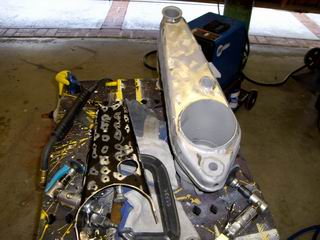
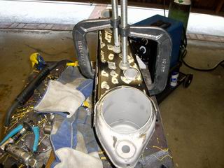
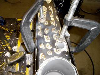
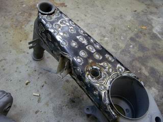
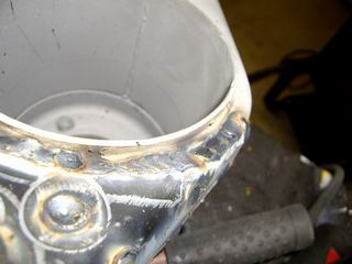
Posted by: Jeff Hail Feb 2 2008, 08:29 PM
They look really ugly will all those plug welds.
After grinding all the welds........one down......
I will grind the other one in the morning and send them off to the powdercoater
Attached image(s)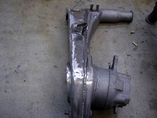
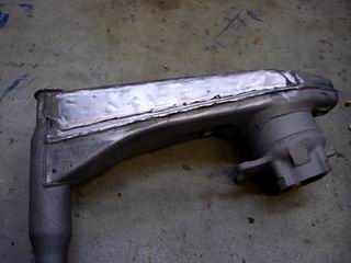
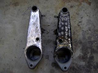
Posted by: Jeff Hail Feb 3 2008, 07:21 PM
Completed all the finish grinding today on the trailing arms.
Threw on some primer til they go to the powdercoater.
Came out slick
Attached image(s)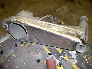
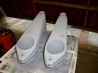
Posted by: Jeff Hail Feb 10 2008, 09:48 PM
Got a lot done this past week.
Stopped in to say hello to Peter at Rennspeed. http://www.rennspd.com/
Ended up leaving with a perfect set of GT Rocker moldings and an Oil presure/ temp gauge I have been hunting. The rocker moldings are perfect side to side length. This seems to be a problem with other suppliers. The flared ends also match the steel flares contour perfect.
Never ever stop in to say hello when you have a wallet full of cash at any Porsche parts establishment.
Sent the transaxle out to flip the R&P on the 915. I added a few modifications "since there in there". A hardened steel bearing carrier. All new syncro rings. G50 speedometer Hall sensor for inverted R&P. How much? Do not ask!
And the week culminated with beautiful weather here in SoCal. One full day to work on the car and finish some things up.
I hated to cut the quarter panel but no way to access the inner wheelhouse replacement. It will end up cleaner in the end. Managed to save the pillar in the process. Reminds me of Milchelko's "diggi'n into hell".
Attached image(s)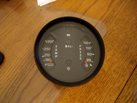
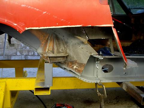
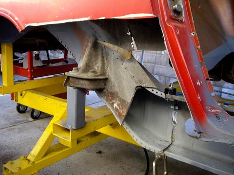
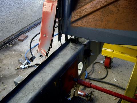
Posted by: Jeff Hail Feb 10 2008, 09:54 PM
No rust left here. All new steel.
Made another fixture to keep the longs in check. Threaded rod with plates on each end. Tack welded to the inner longs. Keeps the dimensions in check and the longs won't splay in process.
Remember to take measurements before you begin cutting off stuff. Especially the suspension consoles
Attached image(s)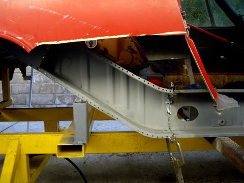
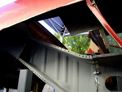
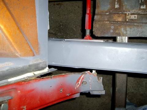
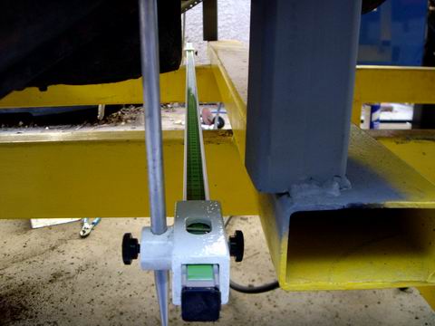
Posted by: Jeff Hail Feb 10 2008, 10:00 PM
More on measuring.
Do not proceed without measuring before you cut. This is vital to returning a chassis to dimensional tolerance. You do not have to high tech equipment. A tape measure will get by if on a budget. Pre- measure both sides before you cut any suspension consoles off.
Attached image(s)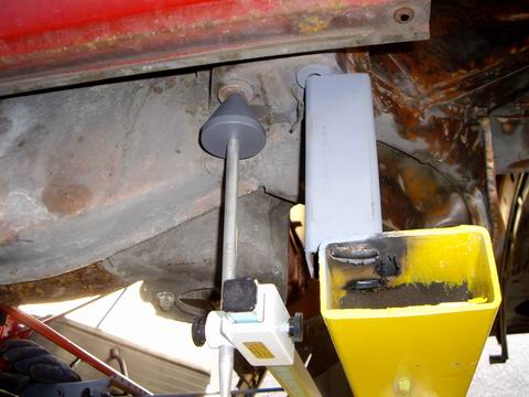
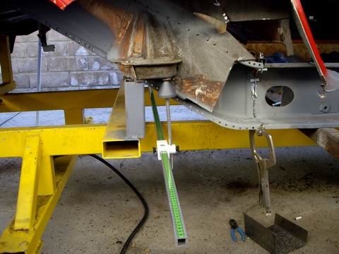
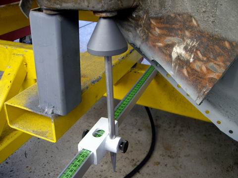
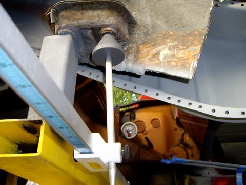
Posted by: Jeff Hail Feb 10 2008, 10:05 PM
Finished the long connection at the rear rail. Added a sleeve at the joint. This will strengthen the connection and eliminate the flex at this area that 914's at notorious for.
Notice I punched holes in the sleeve. Since this is a area known for corrosion I did the work from inside the long. No leaks from pin holes in any welds will happen here. Also less finish work required since it is all inside once the long is closed up.
Work smart -not hard!
Attached image(s)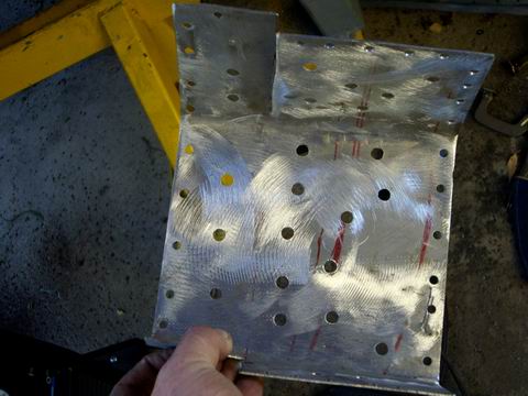
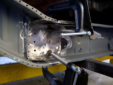
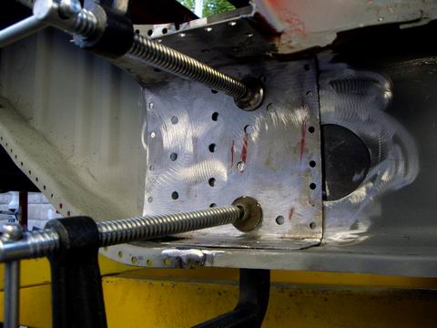
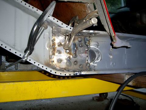
Posted by: Jeff Hail Feb 10 2008, 10:15 PM
Twice as strong as the factory design in this area. No welds from the outside except the outside butt joint equals no water leaks in this area.
I rough fit the new outer wheelhouse ( oops didn't take a pic)
I little more trimming needed but should be installed next weekend.
I am actually considering modifying a shelf where the rear diagonal long meets
the inner long at the firewall. An angled addition of sheetmetal to make water run off and down away from the long. Easy to do and hardly noticeable. More on that later.
Attached image(s)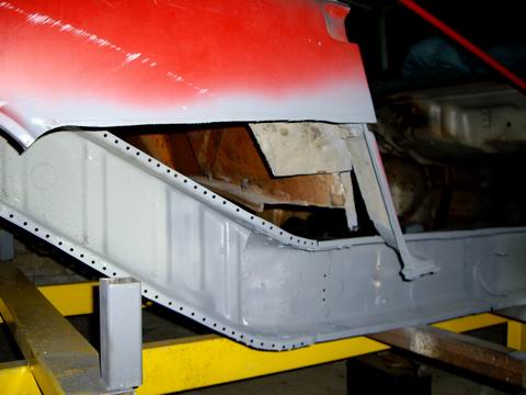
Posted by: Jeff Hail Feb 10 2008, 10:31 PM
Value in scribbled notes:
I am sure this will help someone one day!
Measurements...........
Seat hinge mounting
Attached image(s)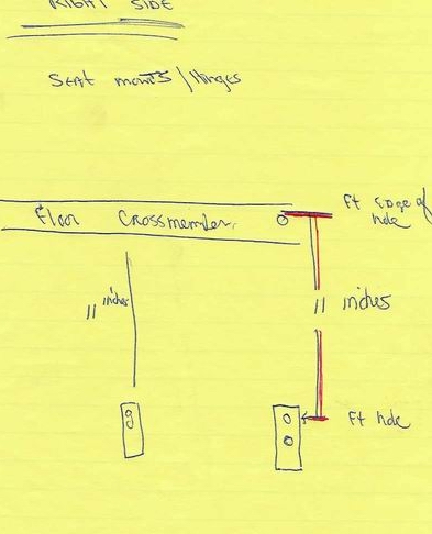
Posted by: Jeff Hail Feb 10 2008, 10:33 PM
More value in scribbled notes:
I am sure this will help someone one day!
Measurements...........
Outer suspension console specs...............
Attached image(s)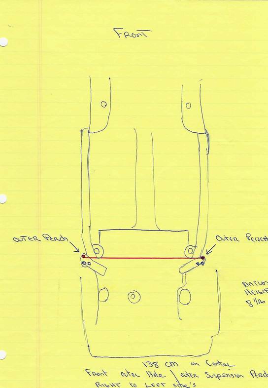
Posted by: Jeff Hail Feb 10 2008, 10:35 PM
More value in scribbled notes:
Measurements...........
Inner suspension console specs...............
Attached image(s)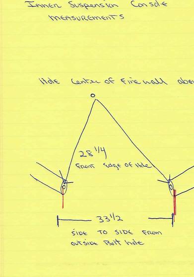
Posted by: Jeff Hail Feb 10 2008, 10:39 PM
More scribbled notes:
Measurements...........
Jack post tube............... if you want your rocker moldings to fit correctly (tube centered in the rocker molding cutout hole)
Attached image(s)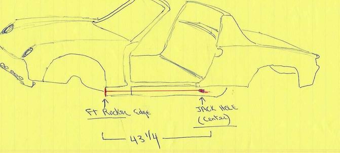
Posted by: type11969 Feb 11 2008, 06:41 AM
Looks familiar . . . just much nicer!
-Chris
Posted by: Eric_Shea Feb 11 2008, 04:45 PM
How long before my "Rock Crusher" is done...
http://www.914world.com/bbs2/index.php?showtopic=80797
Posted by: Jeff Hail Feb 11 2008, 08:44 PM
Two weeks! Isn't that what all shops say?
Posted by: Twystd1 Feb 12 2008, 12:08 AM
Eric, I have seen Jeff's work first hand.
Your rock crusher should be done in 9 days if I read it right.
C
Posted by: Jeff Hail Feb 13 2008, 12:26 AM
Might as well add this to the thread too:
The design make's everything a one man operation. The width of the upper bed is 32 inches wide which fits between the rear inner console ears that are the lowest part of the car. The height from the ground up was based on the maximum height of the common floor jack +2 inches (adding 2x2x 6 foot) cross bars that sat on jackstands and the bench rolled right underneath with a hair to spare? Of course easy access to gain access and roll around underneath on a creeper was taken into account.
Attached image(s)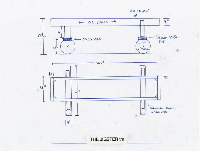
Posted by: Twystd1 Feb 13 2008, 02:52 AM
This is my favorite thread on this site so far. I LOVE THIS STUFF.
Clayton
Posted by: Zimms Feb 14 2008, 04:57 AM
Thanks for posting all of the sketches. I am going to be starting something similar this summer.
Posted by: Jeff Hail Feb 17 2008, 06:44 PM
Lets make some Sill Triangles
Made 2 templates. The first one is actual size after the bends (silhouette) of the mounted original. The second is 3/8 larger all the way around.
Cut out the sheetmetal using the larger template and then trace the smaller (silhouette) template onto the cutouts. Then drill the holes. I am making right and left sides.
Make some relief cuts so the bends don't buckle the flat area's. I tacked some really small welds where the sill plate doglegs over the bracket for strength.
These were the tools used in the process and a metal scroll saw to make the cutouts .
Finished triangle next to the original.
Attached image(s)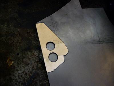
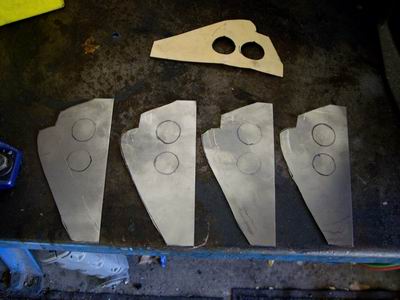
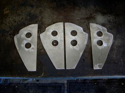
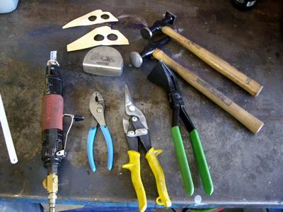
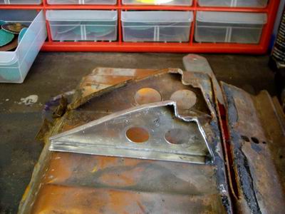
Posted by: Jeff Hail Feb 17 2008, 06:46 PM
Primed set of 4 right and left side triangles.......
Attached image(s)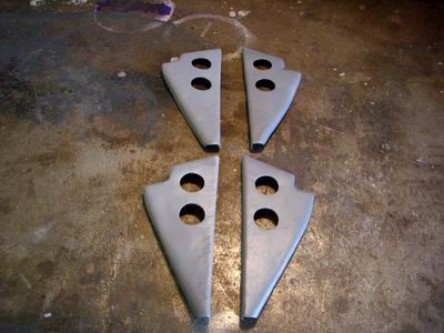
Posted by: watsonrx13 Feb 18 2008, 05:58 AM
Jeff, very nice job on the triangles. BTW, what gauge metal did you use?
-- Rob
Posted by: Jeff Hail Feb 18 2008, 09:55 AM
Jeff, very nice job on the triangles. BTW, what gauge metal did you use?
-- Rob
18 gauge - Factory used a metric equivalent of 17.
Posted by: Wes V Feb 18 2008, 07:35 PM
Jeff;
I just wanted to say thanks again for the sketch of your working platform.
I just had 60 feet of steel delivered so I can build my own.
Wes
Posted by: Jeff Hail Feb 18 2008, 11:13 PM
Jeff;
I just wanted to say thanks again for the sketch of your working platform.
I just had 60 feet of steel delivered so I can build my own.
Wes
Even know its thick metal weld slow. Start square -end square. Tack the four sides of the frame together first then weld the seams and corners. This way if it goes sideways you can break one of the tacks to adjust. If you have a couple of buddys doing nothing have them stand on the frame with backs to you while you are welding to keep if from distorting. If not sandbags work. If the main frame starts lifting a corner stop welding, flip the frame over and let it cool. Then weld the legs and crossbars. The diagonal leg supports will need to welded very slow in one or two inch bursts. If you weld too fast it will draw the crossbars up under heat and the rack will rock on 3 legs.
You will have enough left over to use as crossbeams between the rack and car body. The three fixtures I made are secured at the front suspension crossmember mounting, rear just in front of the rear bumper and under the rear suspension ears. The ones under the passenger compartment are loose and can be removed for access as needed or slid forward/ backward as the floor for the most part is flat.
Good luck
Here is a better pictured unloaded
Attached image(s)
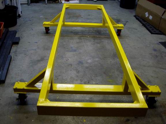
Posted by: Wes V Feb 19 2008, 09:30 AM
What you may find interesting is that I plan on using a contractors lazer level that throws a 360 degree line to ensure the main frame is true. (they cost something like 5 grand, but can be rented) I can set it in the middle of the main frame during set-up and welding to ensure it's in a true flat plane.
Once that's done, I'll weld on the legs and lower out-rigger (with wheels).
When all is done and sitting on the garage floor, it will not be level (due to the slope of the garage floor, but will be a true flat plane to work off of.
(hopefully I can do the main frame this week-end and will post up photos)
Wes
Posted by: Wes V Feb 22 2008, 07:52 PM
Here is a photo that shows how I ensured that the main platform frame is "true".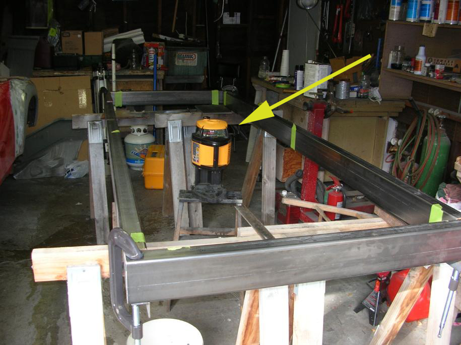
The item that is pointed at is a laser level that I borrowed from a contractor friend. When first turned on, it levels it's self and then throws out a level laser light (red) a full 360 degrees.
The read line doesn't show in the photos, but having it hit the inside edge of the 2X4 tube, you can shim it up as required to make it level. I used a small framing square and put a piece of tape on it. You go to the "high" corner and place a mark on the tape where the laser light hits it. Then go to each other corner and shim it up to match.
Once the frame is moved, it will not be level, but it will be "true".
Wes
Posted by: Jeff Hail Feb 22 2008, 08:03 PM
Good start Wes.
Lets see a new thread on the car to the left. I spy a AA outer wheelhouse in the background..You do know you are going to need a bigger garage?
Posted by: Wes V Feb 22 2008, 08:19 PM
Good start Wes.
Lets see a new thread on the car to the left. I spy a AA outer wheelhouse in the background..You do know you are going to need a bigger garage?
The "clutter" shown in the photo is proof that a bigger garage would be nice.
I've resisted doing a thread due to jumping around a lot on the project. I do have my own site where I'm documenting stuff. There isn't a lot there yet, but here is a link to the "flare-diary" that covers the front flares (I can't do the rears until rust repair is addressed.
http://www.performanceforum.com/wesvann/914a/flare-diary/flare-diary.html
Wes
Posted by: Jeff Hail Feb 23 2008, 08:10 PM
Another day with rain.
Cut and fitted the outer wheel house. Still need to do some cleanup grinding on the rear inner long (rail) before I can weld up the wheelhouse.
In the last photo you will notice a hole on the wheelhouse (right center) above the two larger holes. This is the location of the factory pilot hole for placement of the outer suspension console. The AA part does not come with the hole and it needed to be transfered from the old part. If you are using stock consoles that hole is critical.
Attached image(s)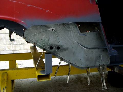
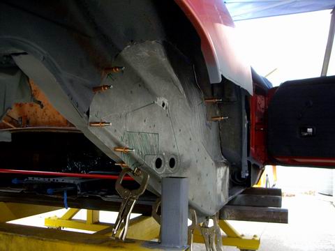
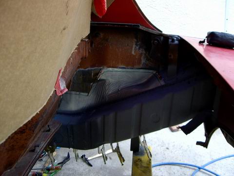
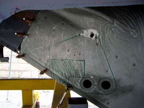
Posted by: Jeff Hail Feb 23 2008, 08:15 PM
Interior brace to keep the longs in check. It is adjustable and held with a few tacks on each inner long. Most projects would not require this.
Attached image(s)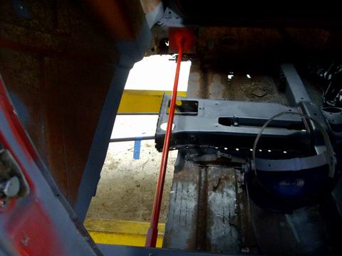
Posted by: Jeff Hail Feb 23 2008, 08:19 PM
Inner wheelhouse all the way to the door opening. Replacing it all the way forward is actually easier and reduces the chance of leaks in the future.
Last photo from below. The contour of the new part fits the original area pretty good.
You might notice the new panel is fitted behind the original sheetmetal? The reason for this any water spray from spinning tires will of course find its way down via gravity. With no outside seam there will be no place for water to enter. Make sense? This will require more work inside the engine compartment but I am not building a show car.
Attached image(s)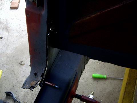
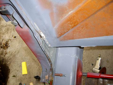
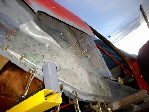
Posted by: Jeff Hail Feb 23 2008, 08:32 PM
Checked the fitment of the outer rocker and sill plate. It was nice to see these parts get some daylight.
Before I weld the wheelhouse up I need to install the J-Tube for the air delivery system and also the C-clamp for the silencer.
Then I pulled it all apart again and sanded the wheelhouse for a coat of epoxy primer. Much easier to put some primer on the area's now that will be soon be a closed box.
Attached image(s)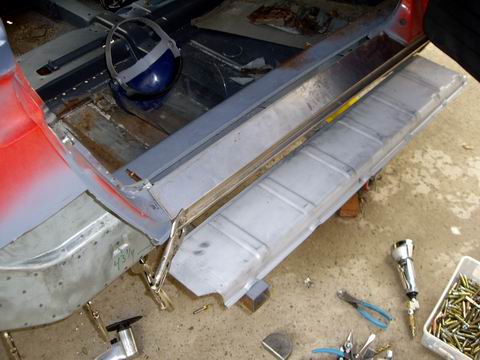
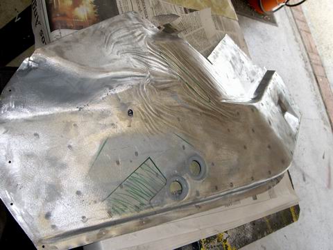
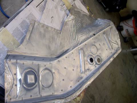
Posted by: Headrage Feb 23 2008, 08:45 PM
I've been hanging out here for quite a while but for some reason never saw this thread.
I bow to you for the work and effort you have put into the car...
Posted by: Jeff Hail Feb 28 2008, 07:04 PM
Trans is done
915, flipped ring gear for mid engine use. Aftermarket steel bearing retainer installed. G50 speedometer pickup (Hall sensor) installed on the right side plate.
Gears:
1st AZ (11:35)
2nd HW (18:32)
3rd NT (23:29)
4th QQ (26:26)
5th ZD (38:30)
Ring and pinion (8:31)
Attached image(s)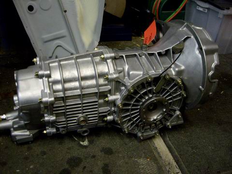
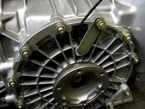
Posted by: Jeff Hail Mar 1 2008, 05:22 PM
Completed the metal prep on the outer rocker panels, inner firewall halves and floor.
Nice when everything is within arms reach.
Have a thing for body hammers. Can you tell which one's get used the most?
(50 year old Proto, all the rest are Martins)
Time to prime. 2K epoxy primer, gotta have fresh air!
Some of the primer will get ground off and/ or burned away on installation of these panels. It's a lot easier to have corrosion protection on before than trying to get it into little crevices and closed areas. Spray guns do not like curves and corners. Work smart not hard!
Attached image(s)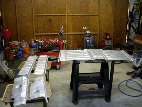
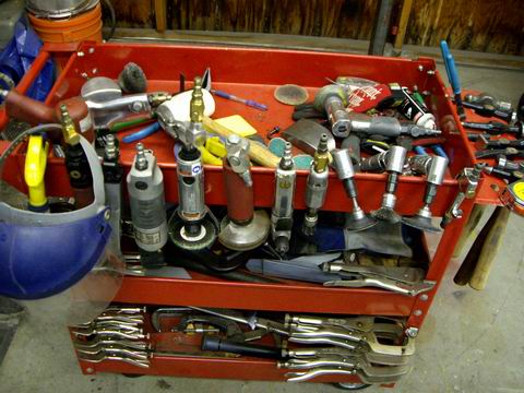
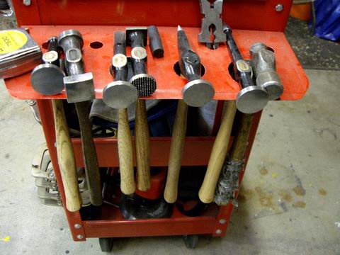
Posted by: Jeff Hail Mar 8 2008, 07:30 PM
Good day to burn some metal
Finished the metal work on the right rear rail/ long......Rt inner long prepped and epoxy primered last week.
Sprayed some Wurth sprayable sealer inside before I close it all up. Put some extra sealer around the sleeves inside the long. Water creeps!
Attached image(s)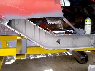
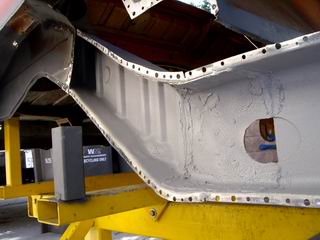
Posted by: Jeff Hail Mar 8 2008, 07:34 PM
Rt rear wheelhouse installed and welded!
The area at the inner rail joint is all plug welded. Various plug welds around the perimeter where the original wheelhouse meets the new then seam welded where the panels overlap.
I discourage butt welding the inner wheelhouse for safety, structural and strength issues.
Attached image(s)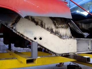
Posted by: Jeff Hail Mar 8 2008, 07:37 PM
All exterior welds ground down and finished.........
A coat of etching primer until tomorrow when I can grind/ finish the inside
of the wheelhouse in the engine compartment.
Attached image(s)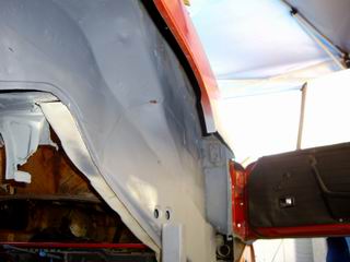
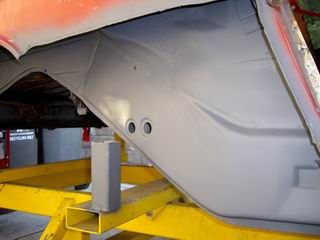
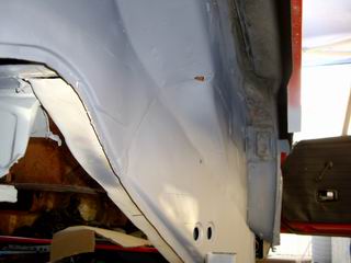
Posted by: Jeff Hail Mar 8 2008, 07:38 PM
Finished welds at the inner long to rear long joint. Clean!
Attached image(s)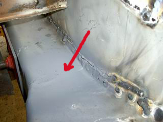
Posted by: Wes V Mar 8 2008, 08:33 PM
Jeff;
This might be jumping ahead, but I've got a question for you.
In the following photo, you show the frame rail section purchased from AA.
Is there another "layer" that goes over this and hides the corrugations, creating a double skin panel? It would be put in place prior to re-installing the engine tray, engine mount, rear suspension bracket, and battery tray?
My car seems to have a double skin panel in this location. (the outter skin rotted due to battery acid, the corrugated section looks reasonable)
I called AA and was told by them that the suspension console (and such) gets welded directly to the part shown in your photo. I'm pretty sure they are wrong.
I've removed the engine mount on the drivers side, and the exposed section of the frame rail is smooth.
Wes V
Posted by: Jeff Hail Mar 8 2008, 09:15 PM
Jeff;
This might be jumping ahead, but I've got a question for you.
In the following photo, you show the frame rail section purchased from AA.
Is there another "layer" that goes over this and hides the corrugations, creating a double skin panel? It would be put in place prior to re-installing the engine tray, engine mount, rear suspension bracket, and battery tray?
My car seems to have a double skin panel in this location. (the outter skin rotted due to battery acid, the corrugated section looks reasonable)
I called AA and was told by them that the suspension console (and such) gets welded directly to the part shown in your photo. I'm pretty sure they are wrong.
I've removed the engine mount on the drivers side, and the exposed section of the frame rail is smooth.
Wes V
The factory piece has the corrugations as a reinforcement on the inside of the rail. The outer overlay is what you see in a factory car. The corrugated piece does not connect to the outer wheelhouse as it only on one side and then bends over the sides of the box about an inch and half. My take is it keep's the rail side from collapsing under suspension loads ( compression, rebound and side loads). The corrugated reinforcement extends all the way down to the seatbelt anchor plate but is basicly flat once it meets the straight inner long.
The AA part is thicker than the original inner 3 sided box but not equal to both pieces of metal combined. I question this myself and will be reinforcing this area in mine.
Here is a picture of my old part cut out. You will see how it is made up.
Attached image(s)
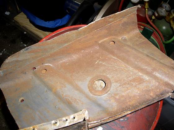
Posted by: Jeff Hail Mar 8 2008, 09:25 PM
Here's a couple pics that better show the rear rail/ inner corrugated reinforcements.
This area was a little different on very early cars. It was not as robust.
The later cars had little pieces here and there to reinforce parts of the car better.
( striker brackets behind the lock pillar's and the front inner longs below and inside the hinge pillar)
Attached image(s)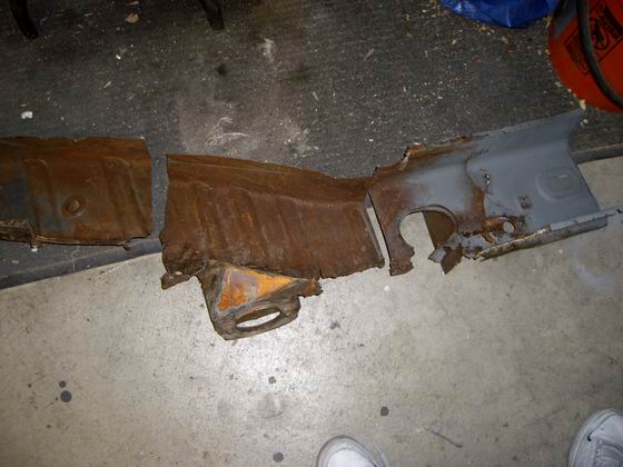
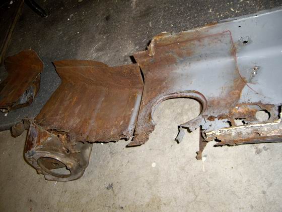
Posted by: Wes V Mar 8 2008, 10:54 PM
Thanks!
That's pretty much what I thought.
So, in the factory installation; the corrugated section stiffens the side wall, but isn't welded to the other side of the box.
The outer (smooth) section is what welds to the other side of the box.
What AA is selling isn't technically correct, in that it replaces the two piece "composite" that the factory used.
Posted by: Jeff Hail Mar 8 2008, 11:26 PM
Thanks!
That's pretty much what I thought.
So, in the factory installation; the corrugated section stiffens the side wall, but isn't welded to the other side of the box.
The outer (smooth) section is what welds to the other side of the box.
What AA is selling isn't technically correct, in that it replaces the two piece "composite" that the factory used.
Yes,
Yes,
Yes ....because it it easier to manufacturer in one piece. For the most the AA part will be sufficient. Most moden cars have frame rails that are made exactly the same way. (ala "crush zones")
Posted by: Jeff Hail Mar 9 2008, 07:58 PM
Finished grinding the welds on the inside of the wheelhouse and some more epoxy primer.
Is it perfect? No there is a thin weld bead where it was sectioned and I did not want to grind it too thin. Just above where the battery tray mounts is the most noticable. I can live with that as everything else is all good steel now.
Also fitted the lock pillar to the door and welded it up. These were brazed by the factory where they meet the sill and it took some time removing the old brass. A few rust pits where the pillar goes horizontal wiped clean with some media blasting.
Attached image(s)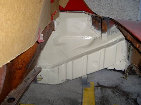
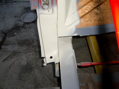
Posted by: Jeff Hail Mar 16 2008, 09:41 PM
Sean,
This is what you are looking for..............
These measurements were taken from an undamaged car and cross referenced to mine. The measurements on the inner ear will vary car to car due to rust, collison, console fatigue etc. Expect a 1/4 variance when you go to take measurements. Those inner ears take a beating over a lifetime.
By triangulating from the hole in the firewall to both right and left ears you will not have a problem when you are ready to set the camber and toe.
Using the measurements in the diagram:
Taking this to another level. You can get the inner console tacked in. Then mount your control arm. Use an "All-thread" with a spherical rod end or piece of tubing where your shock mounts to the control arm, the top of the All-thread goes to the shock tower with some washers. Base the length of the All-thread on your normal ride height (sitting on the ground). Then using a camber gauge check it to see where you are before you weld everything solid. Install a wheel and tire and you can also check toe while static.
Attached thumbnail(s)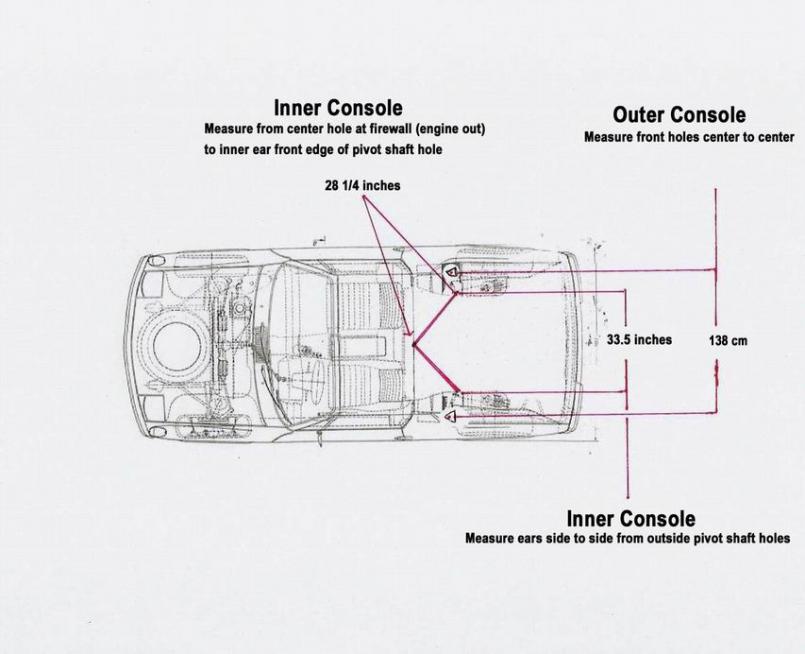
Attached image(s)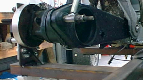
Posted by: Gint Mar 17 2008, 05:55 AM
Posted by: sean_v8_914 Mar 17 2008, 02:38 PM
thanks Jeff. I made some door gap bars with turn buckles also. I'll go make some "shock simulators and check alignment spec with a wheel back on. Im about to weld in teh ear and Im wondering if the heat induced wil move the car. Brer and I did teh cross check body measurements per teh factory manual last night. amazingly everything is within 1/8th to 1/16th. I will be very mindfull of warping,. next is teh inner long stiffener made by ENGMAN.
I used teh #s from your yellow pad schetch posted earlier to tac in teh ear. this new dwg is super sexy.
Posted by: sean_v8_914 Mar 17 2008, 02:40 PM
HOLY COW!!! it measured correctly 1st shot. Im going to buy a lotto ticket (after alignment check)
Posted by: brer Mar 17 2008, 03:03 PM
I've learned alot from this thread.
Unfortuneately it means I now have to redo my entire car.

Posted by: Jeff Hail Mar 17 2008, 06:17 PM
HOLY COW!!! it measured correctly 1st shot. Im going to buy a lotto ticket (after alignment check)
Regarding the suspension console:
Nah it won't warp. Not enough constant heat in that area welding thin to thick metal.
Just move around with the gun a bit and get your buddy holding the beer to grab an airhose and blow to cool in between welds.
Regarding the Engman kit:
Go slow......really slow.....tack first .........then alternate the plug welds as you go on the 3 pieces. DONT weld one piece in one shot. Move around...get that buddy to blow compressed air around the weld zones. If you think its getting too hot stop and wait then go back.
Posted by: sean_v8_914 Mar 17 2008, 11:48 PM
thanks for the warning. I'll go left, right, front, back.
Posted by: Jeff Hail Mar 20 2008, 09:08 PM
Little things take time!
Actually about 15 minutes
Fabricated new brackets for the airtubes. Not concerned if they look pretty. Once they are in they will never see daylight again. Removed the original, smacked it flat with a finishing hammer. Traced onto a sheet of 20 gauge steel and cut it out with hand nibbler.
I destroyed one removing the tube from the car and the other one was a non-existant little patch of iron oxide that was swept away.
Last of the original
Rough cut and bends
Final fit to the tubes
Will drop the tubes off at the media blaster tomorrow.
Attached image(s)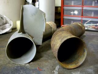
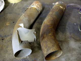
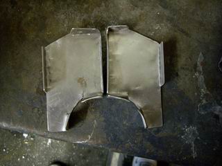
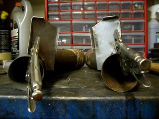
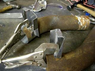
Posted by: Jeff Hail Mar 22 2008, 07:36 PM
Media blasted the air tubes. Welded the brackets I fabricated and epoxy primed, wet on wet with a final coat of Alu-Zinc. They will never ever rust again!
Attached image(s)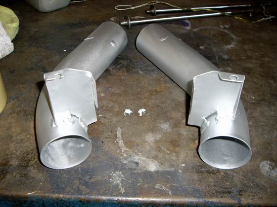
Posted by: Jeff Hail Mar 22 2008, 07:41 PM
Repaired the rust in the passenger side lock pillar.
Cut out the rusted area highlighted in yellow.
Cut some backing pieces and tacked them in. Being the metal is so thin
in this area it is a must. Even on the lowest heat setting on my Miller 180 it can still blow holes. Little fast trigger pulls.
Attached image(s)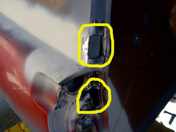
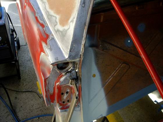

Posted by: Jeff Hail Mar 22 2008, 07:47 PM
After welding and then slowly grinding the two areas.
The area where the air vent is is tough to get a grinder into. This rea has to be right or the door weatherstrip will not seal correctly.
Attached image(s)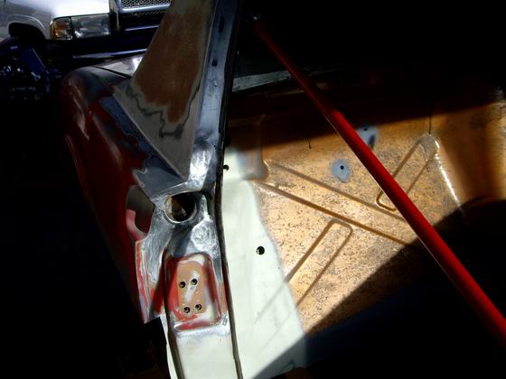
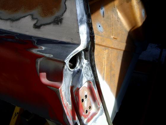
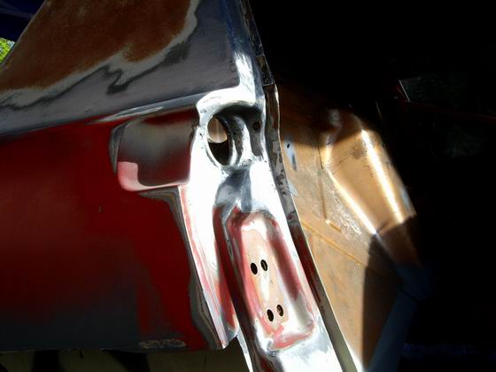
Posted by: Jeff Hail Mar 22 2008, 07:49 PM
Some epoxy primer after shaping.
Oops closed the door on wet primer! Thats how I know the weatherstrip seals good.
No sail panel molding fastener holes either. Welded those up too.
The backing plates I welded in on the backside of the pillar.
Attached image(s)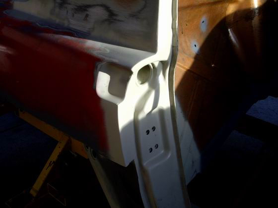
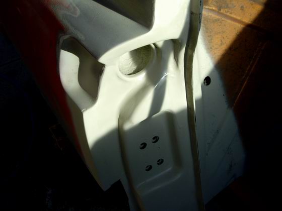
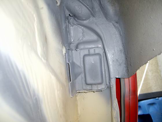
Posted by: sean_v8_914 Mar 23 2008, 10:25 AM
Jeff, what do you recommend to clean this up. that white paint, layers of old glue, crusty has got to go. sand, grind, paint stripper...?
Attached image(s)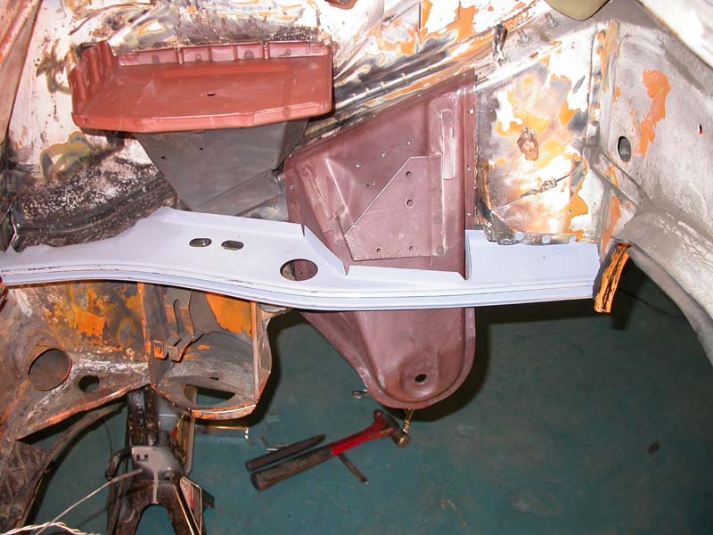
Posted by: sean_v8_914 Mar 23 2008, 10:27 AM
I was also thinking about fastening the battery tray and support with screws for future removal for cleaning.
Posted by: Jeff Hail Mar 23 2008, 01:35 PM
Get in there with a course wire wheel to remove any loose scale and coatings.
Depending on what you find underneath you may need to do some rust repair.
With the amount of pitting I see in the photo I would media blast the area, even some light blasting with sand will get rid of the rust . Refrain from grinding as that will remove/ thin the metal.
The white undercoating is factory primer. You can featheredge this back until you find clean metal and work on the localized area. A new product has come to the US market about a year ago. 2k Epoxy primer available in a rattle can perfect for small spot repairs such as yours.
http://www.autobodytoolmart.com/showproduct.aspx?productid=14526
http://carpaint.blogspot.com/2006/03/spray-max-primer.html
Battery tray fastened with screws? Bad idea. 25-30 pounds bouncing around will
tear it loose quickly. At least weld the lower bracket to the rail. Most of the battery weight is supported here.
Posted by: Jeff Hail Mar 23 2008, 07:01 PM
Installed the rt quarter panel that I had to cut off for the wheelhouse.
Used the butt-welding clamps to secure and align the panel. Making a series of tack weld's while stopping to cool the panel with compressed air.
More tacks, let cool, and many, many more tacks, let cool etc etc etc until one solid weld is complete all the way across the gap.
Attached image(s)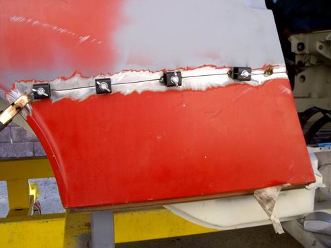
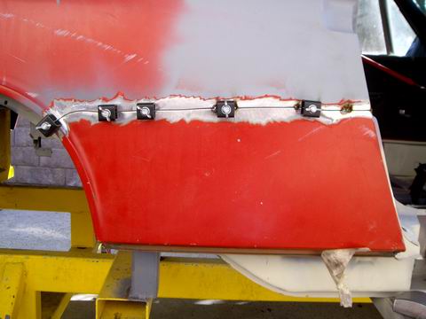
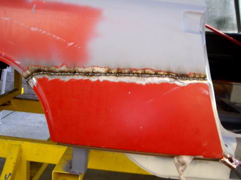
Posted by: Jeff Hail Mar 23 2008, 07:07 PM
When butt-welding along with good weld penetration the key is the grinding and finishing process.
I begin with a spot weld grinding disc to take the crown of the weld down to just above panel height. Move slow and let the panel cool. A grinder will warp thin sheetmetal just like overheating while welding.
Then I use a 3 inch 36 grit disc on a angle die grinder to take the crown down a little more.
Then I switch to a 6 inch flat flap disc and follow the crown back and forth eliminating any high spots.
Attached image(s)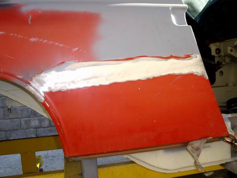
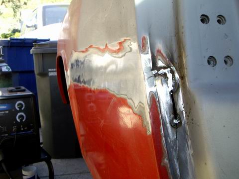
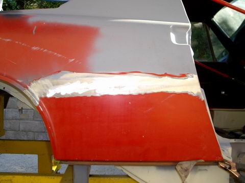
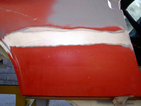
Posted by: Jeff Hail Mar 23 2008, 07:14 PM
At the end I then use a different type of flap disc on a straight die grinder. I follow just the butt weld crown. This will level the weld and not dig into the surrounding metal. This type of disc is like 250 grit emery cloth.
Then I take a dual action sander with 40 grit and enlarge the area of finishing. The DA really smooths the weld and surrounding area well. Switch to 80 grit paper and then 120.
I then knocked down the inside of the qtr panel with 80 grit 3 inch discs and then a squirt of primer. I will let the primer dry and block sand the the panel Tuesday.
No bondo.
Will see after block sanding. Most likely just a skim coat of metal glaze is all it will require if that.
Still need to finish the lock pillar joint but I had plans and have to run.
Attached image(s)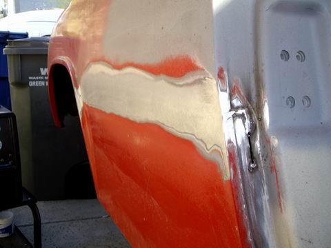
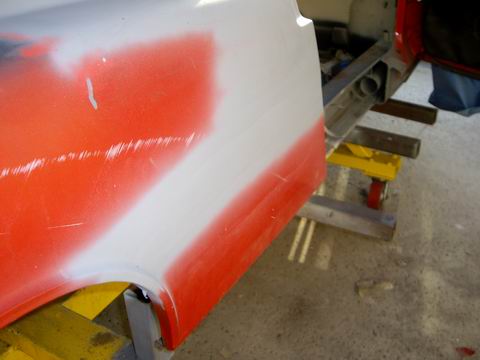
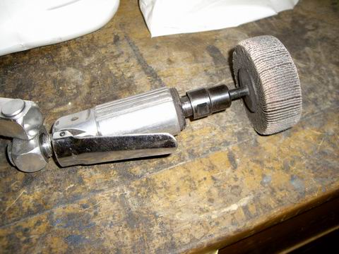
Posted by: sean_v8_914 Mar 23 2008, 09:08 PM
could you send me a close up of your butt weld? ...or the high res version of that photo
Posted by: type11969 Mar 24 2008, 05:39 AM
Jeff-
I think you should take an extended vacation in Philadelphia. Bring your tools.
-Chris
Posted by: Wes V Mar 24 2008, 08:43 AM
Dang Jeff, I'm confused about the sequence on how you are doing this!!
In your last entry, you are welding the fender back in place.
And yet it doesn't look like you have welded the outer suspension bracket back on!!!
I know (from reading this string a lot) that you are planning on installing the Tangerine Racing (CFR) suspension relocation set-up, but from what I've been able to figure out, you will need that fender partially removed to weld everything in place! (the gusset plates in particular)
So, did you already install that and didn't say anything or what?
Are you planning on installing metal flares and feel confident that the opening for the flare (prior to welding in place) will allow you to weld in the suspension?
Wes V
Posted by: Jeff Hail Mar 24 2008, 08:15 PM
could you send me a close up of your butt weld? ...or the high res version of that photo
Lets see how large a file the site will let me post. I always reduce them out of courtesy to the site owner. Someone is paying for web space.
Attached thumbnail(s)
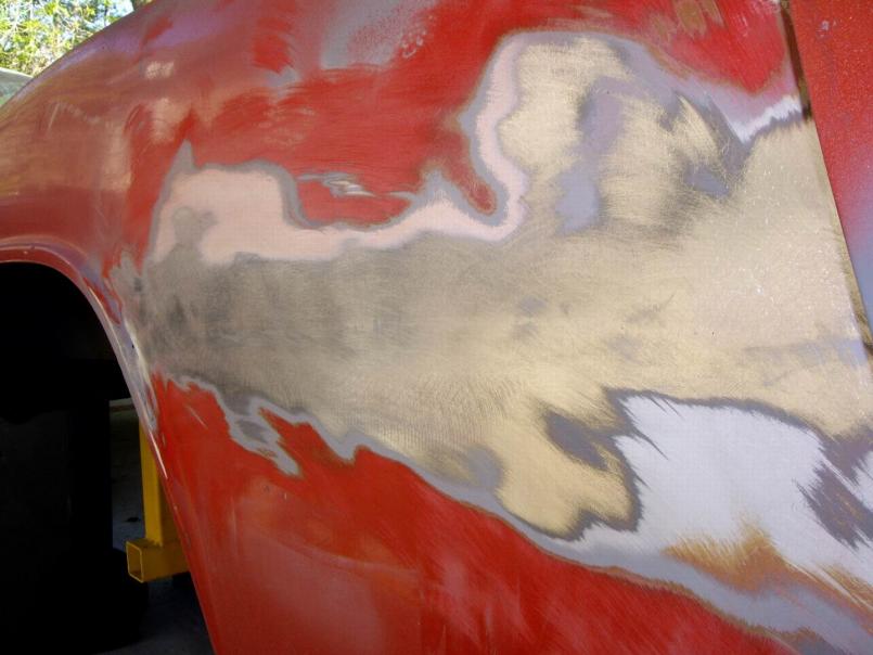
Posted by: Jeff Hail Mar 24 2008, 09:04 PM
I started blocking the primer today and ran into 2 prior repairs above the weld line.
Pink filler and yellow filler. Get out the "Mud Hog". Oh well it's only a little primer wasted.
The pink filler is below the color coat (copper) and yellow on top of old color where it shouldnt be. Hard to featheredge when it is like that. 6 coats of paint and primer I counted not including filler. The old filler is very thin and doesnt cause any concern. The red does as it is acrylic enamel or possibly Nason synthetic enamel and it has to go away because past experience dictates it will lift or react with solvent. It will get stripped even know the substrates are in suprisingly good condition.
As far as the butt weld line there are 2 small low spots (below the pink filler) and 1 more at the lock pillar that can be bumped out with a hammer and dolly or skim coated.
I have a set of steel flares and most likely will go that route although I have been talking to a fiberglass supplier that is willing to do a wide street weight version of belt line qtr panels with a reinforcement in the debris impact area. We will see?
Wes,
Lots of room under the wheelwell to install the pickups. All I need is a 3 inch cutoff wheel, an airsaw and a angle grinder.
Attached image(s)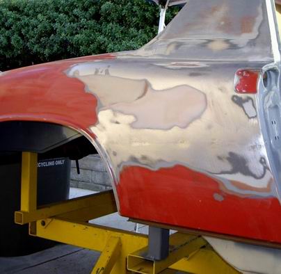
Posted by: Jeff Hail Mar 24 2008, 09:11 PM
As close up as I can get of the butt weld line blended in
Attached thumbnail(s)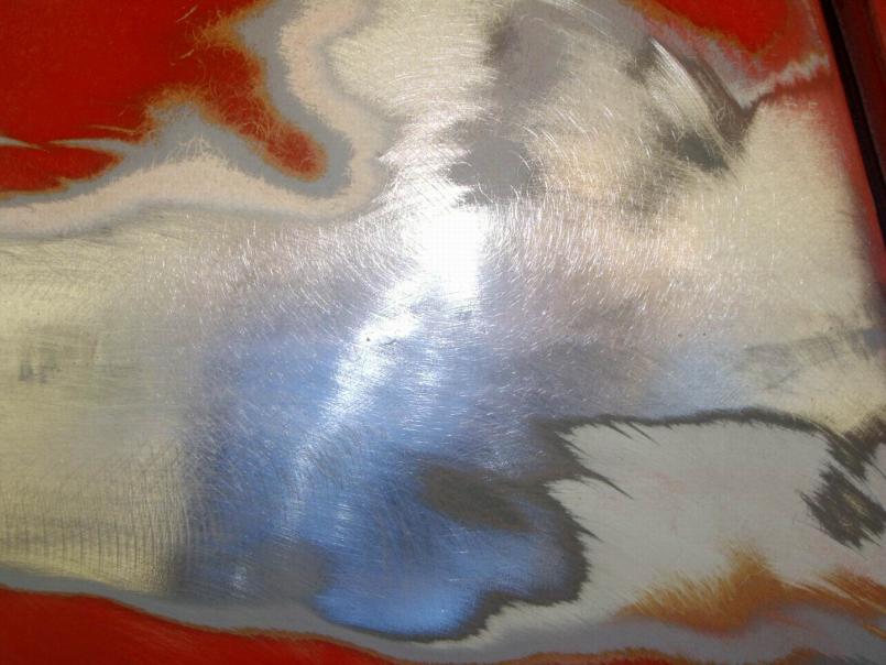
Posted by: 1970 Neun vierzehn Mar 24 2008, 09:22 PM
The title of this thread should read......
Carrozzeria Hail
High accolades are in order here, not only for your craftsmanship, but also for selecting a 914 to be on the receiving end of your obvious skill and talent. 
Paul
Posted by: Jeff Hail Apr 10 2008, 09:22 PM
Few days off from "work"........time for play
Fitted the heater tubes. I repaired the passenger side muffler. Was a bit chewed up and falling apart on the rear end of the can . Some resin and mat should keep it together. Sprayed with high temp paint. Never to be seen again. Have not decided if I am going to run heat or not....better safe than sorry.
Welded in the Heater-J tube. Cannot install this later with the firewall on. I tried everyway possible but I really want to get the rocker done and closed up. Decided in the end it would be easier to cut a slit on the firewall and bend it back around the tube.
One important thing. The heater tube exit hole on the replacement inner long does not come flared. This is a load bearing member and flaring the hole is vital to safety. The hole needs to be radiused and the edges flared. I do not have a 2-1/2 inch punch flare so I had to get creative. Ever wonder why aircraft windows are not perfect squares? If they had squared corners they will fatigue and crack. If you round them and flare (chamfer) the opening they will simply flex. Besides the flare adds strength where the metal has been removed.
Attached image(s)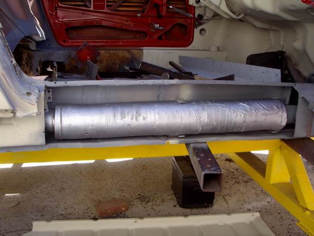
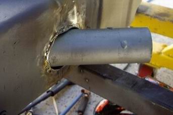
Posted by: Jeff Hail Apr 10 2008, 09:31 PM
Mocked up the firewall and lower reinforcements again (actually before I welded the heater -J tube in). Pays to recheck fit as you go. Small adjustments are easier then big ones that aren't expected.
Clutch and throttle cable conduits lined up perfect. These will be cut to proper length when the time comes.
Attached image(s)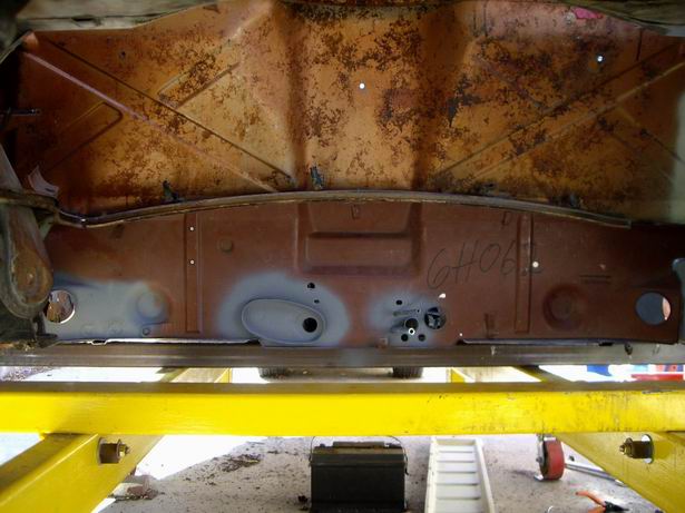
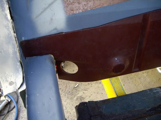
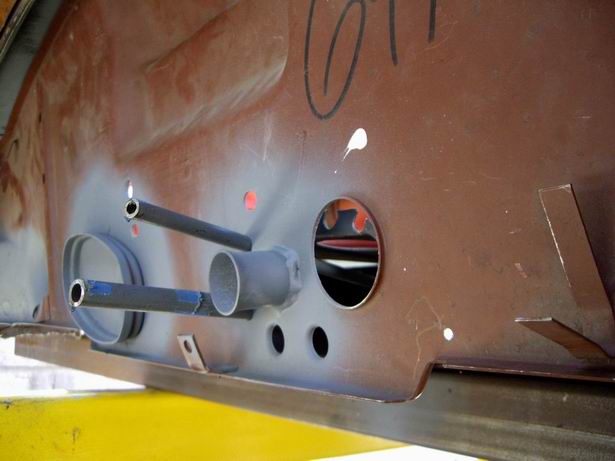
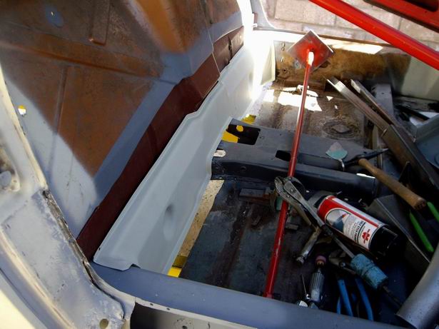
Posted by: Jeff Hail Apr 10 2008, 09:49 PM
Cut and trimmed the new outer rocker panel to fit (I call the outer bolt on part a rocker molding).
At the rear where it fits the wheelhouse was tight so I had to bust a few welds top and bottom to get it to slide in all the way. It was hitting the inner reinforcement. Tried shoehorning it with a body spoon to persuade it but it wasn't moving back where it needed to be.
Added a backer plate at the front which will provide a clean butt weld and something to burn into. The backer is a piece of the new part that was trimmed off.
Final fit and trim..........and ran out of daylight.
Tomorrow I will punch all the holes and get this piece welded up.....
Attached image(s)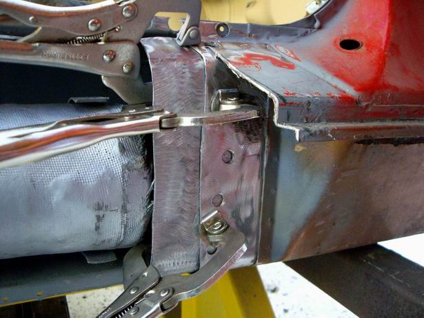
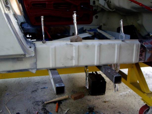
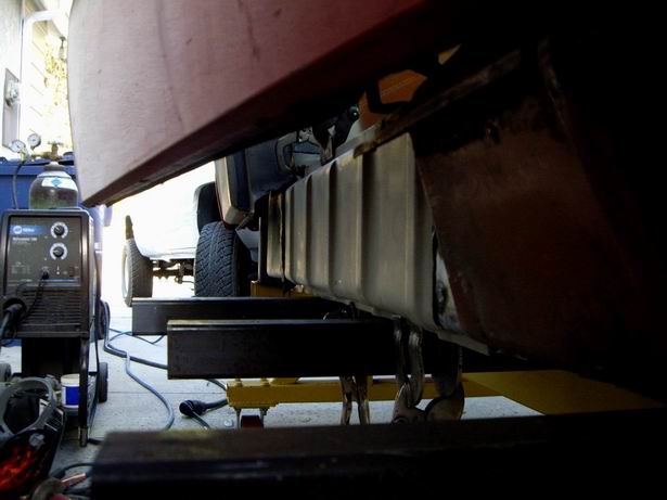
Posted by: craig downs Apr 11 2008, 12:29 AM
Its just incredible what you have done to save this car. Anybody else would have just cut it up.
Posted by: Jeff Hail Apr 11 2008, 01:57 AM
Its just incredible what you have done to save this car. Anybody else would have just cut it up.
All this because an Exige S pissed me off and a friend said take the 914, its free!
Posted by: tdgray Apr 11 2008, 08:39 AM
Great Job Jeff.... keep it up.
Posted by: KELTY360 Apr 11 2008, 10:30 AM
Its just incredible what you have done to save this car. Anybody else would have just cut it up.
Well actually, he has cut it up......and now he's putting it back together.


Amazing work Jeff.
Posted by: Jeff Hail Apr 11 2008, 09:07 PM
Great Job Jeff.... keep it up.
Todd,
You made me laugh my ass off with:
"ass-hat (adj)- One whose head is so far up their rear end it could pass for a hat; used to describe a person who is stubborn, cruel, or otherwise unpleasant to be around".
Thats a great one!
Thanks
Posted by: Jeff Hail Apr 11 2008, 09:18 PM
Welded up the right rocker. I plug welded the top from inside the car. No holes were punched on the new outer panel....the lower was done from underneath the car.
First -it's easier welding thru old steel into new metal
Second- no grinding a gazillion plugs on the exterior. No pin holes on the outside to leak.
Butt weld with a backer at the front and seam welded the rear outer wheelhouse (another area that is prone to water because the outer panel faces towards the front of the car)
Attached image(s)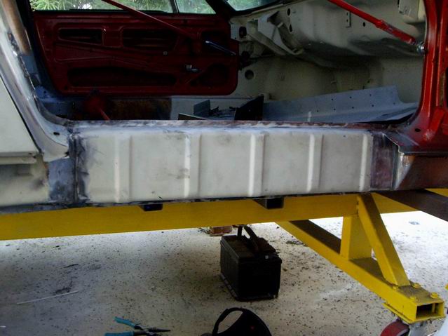
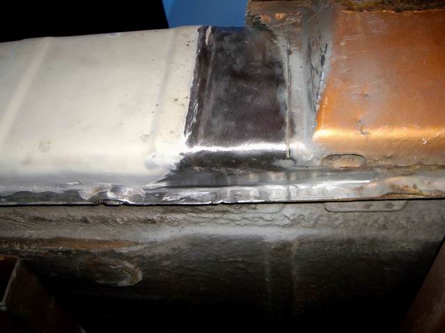
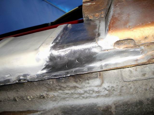
Posted by: Jeff Hail Apr 11 2008, 09:40 PM
Can someone clarify if this is what a 914 rocker is supposed to look like?
I am kind of new at this and mine originally came with the translucent iron oxide version! (sick 914 humor) 
I also misplaced some measurements I noted somewhere. Now where the hell did I put them? Body panels make great sticky notes! 
Day is done for now. A quick squirt of primer and its time for a
Attached image(s)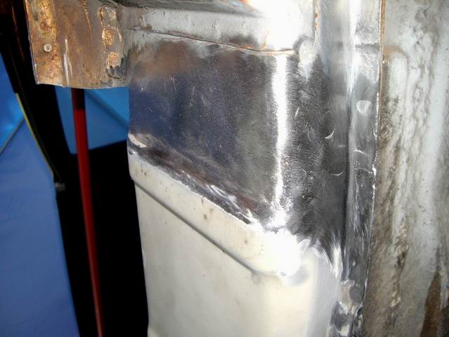
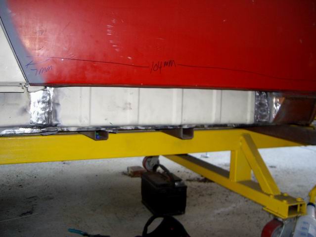
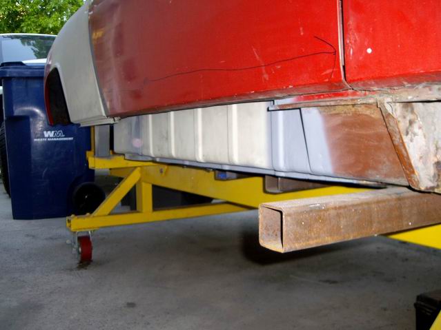
Posted by: Jeff Hail Apr 20 2008, 10:38 PM
Passenger side sill plate is in.
Ran out of C02/Argon so I couldn't weld the sill triangles in.
Good tip....do not throw out those old weatherstrips. They are still important
when fitting parts such as the sill to make sure you get a proper seal on the door shell.
Attached image(s)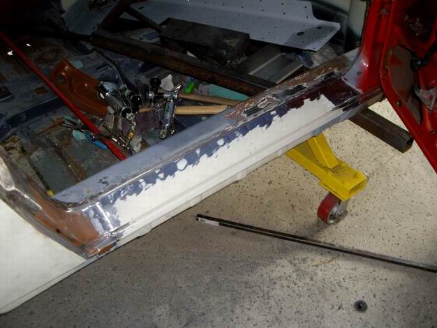
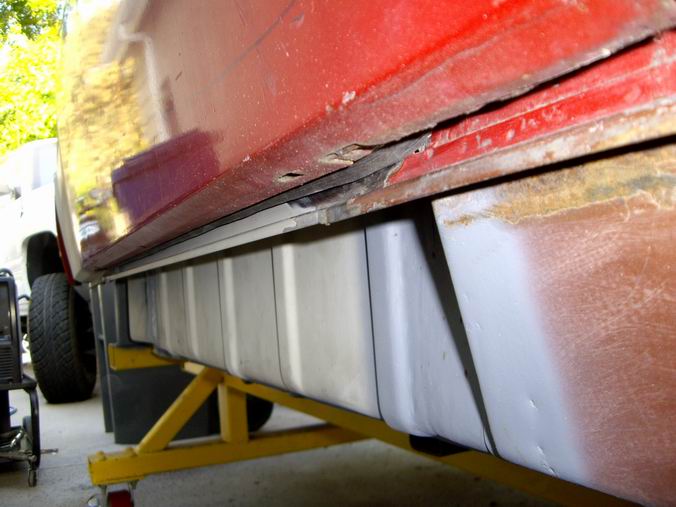
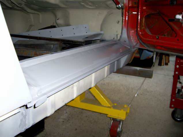
Posted by: Jeff Hail May 3 2008, 10:21 PM
Lite duty this week. Carpal Tunnel sucks.
Welded in the sill triangles I fabricated and prepped the threshold area.
Attached image(s)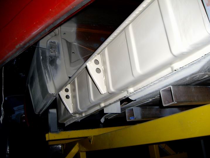
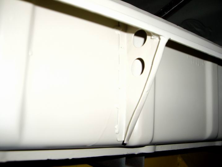
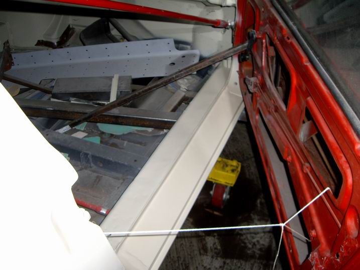
Posted by: Jeff Hail May 3 2008, 10:26 PM
Tomorrow I will coat the gap where the rocker and sill plate meet with Wurth Seal Fix. WSF is closed cell sealer and semi rigid. Water and moisture will not get past it like the factory sealer.
Notice I installed the triangles flat side forward. The factory should have done this so as not to be a catchers mitt for road debris.
Attached image(s)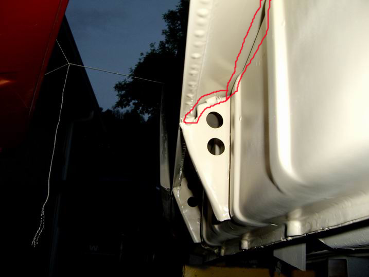
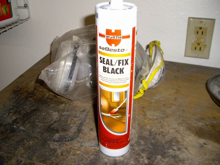
Posted by: Jeff Hail May 3 2008, 10:31 PM
The right tool for the job.
Stripped the right front wheelhouse of its undercoating in about 3 minutes.
Elbow grease....Not!
(Brake Cleaner also works like a charm and strips about everything else in the process if you don't want to invest in one of these.)
Attached image(s)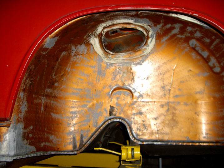
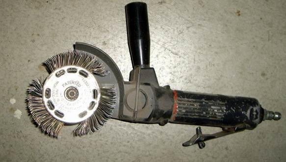
Posted by: Zimms May 4 2008, 06:45 AM
NICE WORK! Keep it coming!
Posted by: Eric_Shea May 4 2008, 08:55 AM
What's that called again?
Posted by: Jeff Hail May 4 2008, 02:08 PM
What's that called again?
Wurth DBS 3500 (aka "the flail")
Posted by: Eric_Shea May 4 2008, 02:25 PM
@ $479.00 that may be worth it for even one car... kinda pricey though when considering a soda blast for $600.
Cool tool. 
Posted by: Jeff Hail May 4 2008, 02:31 PM
@ $479.00 that may be worth it for even one car... kinda pricey though when considering a soda blast for $600.
Cool tool.
They can be found for much less used. DynaBrade also makes a similar one for less. BTW,What did you find out on the brake parts cost?
Posted by: Eric_Shea May 4 2008, 02:50 PM
I found that the pound is $1.95 now!
They should be here at the end of the week.
http://www.pmbperformance.com/catalog/item/1925563/5825883.htm
Posted by: sixnotfour May 4 2008, 05:39 PM
Soda Blast wont remove the nasty seam sealer.
I just did mine and thought the blasting would remove the little I left , Nope had the body shop kid wire wheel the rest, as I was Done.
Posted by: Eric_Shea May 4 2008, 06:37 PM
I just did mine and thought the blasting would remove the little I left , Nope had the body shop kid wire wheel the rest, as I was Done.
Yeah I know...
 Send him my way when you're done!
Posted by: Jeff Hail May 11 2008, 12:16 AM
Stripped the underside rear of the tub to metal and epoxy primed.
First I used the Wurth "flail" to remove the old undercoating. This also removed the majority of original paint. The rest I machine sanded with a Mini DA and a few spots I used Starblast media (transmount bracktets and crossmember). Then some good old fashion elbow grease hand sanding and some solvent.
I removed all of the seam sealer where the inner wheelhouse/ quarter panels meet the floor at the rear. Needed to see if any issues were under there. None found. 
I did leave intact the sealer where the shock tower pockets are. Just took it down a little to have something to bite into and tidy it up.
The Kent solvent kicks ass.
Attached image(s)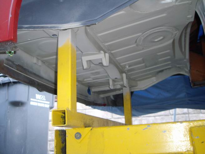
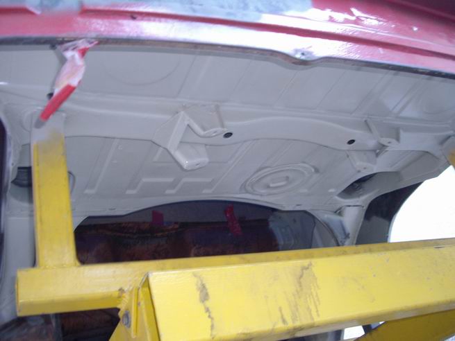
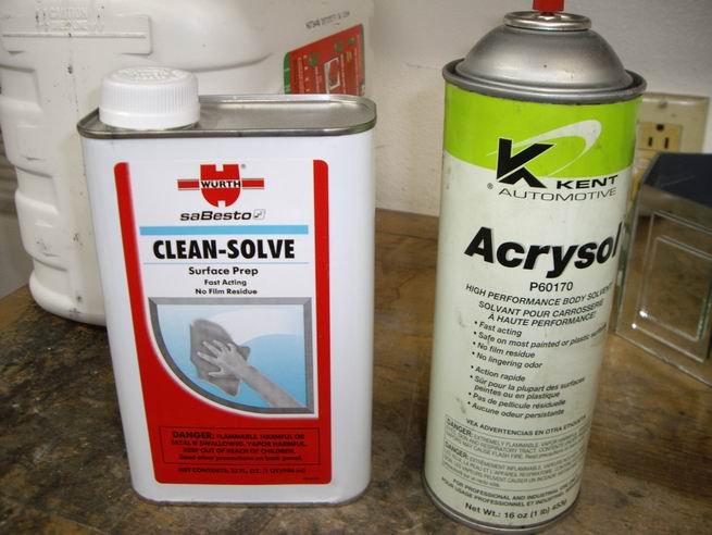
Posted by: Jeff Hail May 11 2008, 02:38 AM
It's midnight and a knock at the door!
Who the hell is at my door at this hour?
Hey dude.... Whoa those came out bitch'n..........
What do I owe you?......A couple cold beer's!
It's nice when the Powder Coater is your bud! Price was right. 2 Stage Powder Coating rocks!
Attached image(s)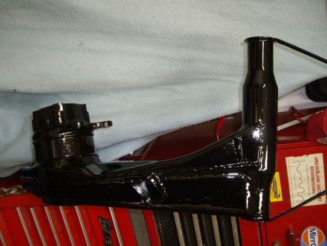
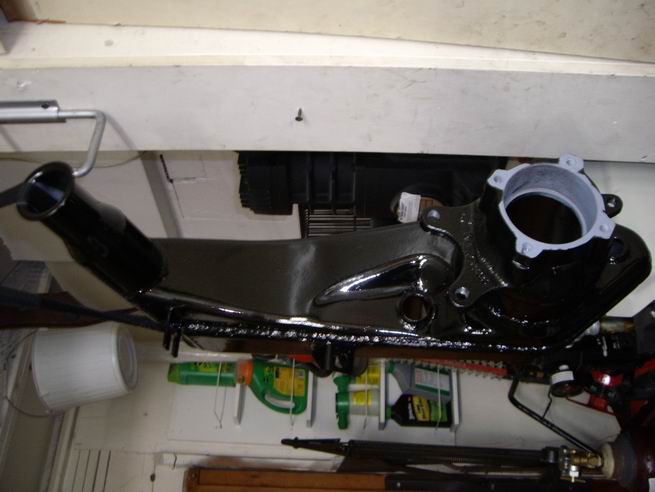
Posted by: Jeff Hail May 12 2008, 10:30 PM
Awesome....printed on the side of a box of Porsche Exhaust Headers. Even the UPS guy had to take time out to read it. Way cool.
AUTHOR: Walter D. Wintle
QUOTATION: If you think you are beaten, you are;
If you think you dare not, you don’t.
If you’d like to win, but think you can’t,
It’s almost a cinch you won’t.
If you think you’ll lose, you’re lost,
For out in the world we find
Success begins with a fellow’s will;
It’s all in the state of mind.
If you think you’re outclassed, you are;
You’ve got to think high to rise.
You’ve got to be sure of yourself before
You can ever win a prize.
Life’s battles don’t always go
To the stronger or faster man;
But soon or late the man who wins
Is the one who thinks he can.
Now who can guess what brand they are?
Posted by: porsche914gt May 13 2008, 12:27 AM
Stahl
New York
Right?
I remember mine had that.
Posted by: Jeff Hail May 13 2008, 06:57 PM
Stahl
New York
Right?
I remember mine had that.
I recall that Stahl stopped making 914/6 headers although you are correct on the box. I got a kick out of the verbiage on the box.
The headers are George Narbel's (ERH) . I had them thermal coated and they shipped em in a Stahl box.
Posted by: kwales May 13 2008, 07:42 PM
Jeff,
Something I've been meanign to ask...
Who makes this tram gauge?
It looks like something I could use.
Ken
Attached image(s)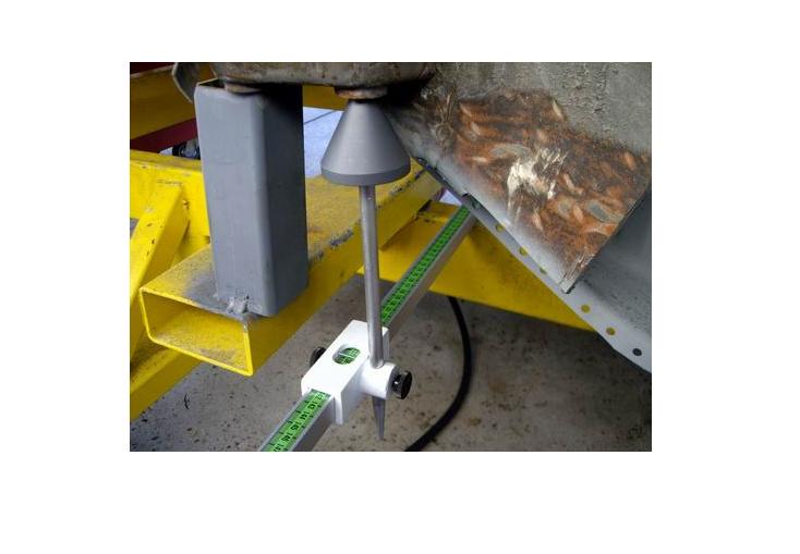
Posted by: Jeff Hail May 13 2008, 11:05 PM
Jeff,
Something I've been meanign to ask...
Who makes this tram gauge?
It looks like something I could use.
Ken
Champ Frame Equiptment
Google "Tram Gauges" and you will find a host of suppliers
Posted by: Jeff Hail May 16 2008, 12:12 AM
I was prepping a post and the lights went out! The site went down. It's like running out of MIG gas!
(Preview of next weeks board meeting:o)
Rt fender off. I new I had some rust at the top by the cowl. Not as bad as I expected. Fender was removed as a skin leaving the cowl extension intact.
The upper cowl extension will get cut out and replaced. Easy piece to fabricate.
I swear that piece was designed for Dzus fasteners!
The cowl itself is ok at the horizontal area but the side will need some new metal.
I used the Wurth "flail" to remove the sealer and take it down to bare iron.
The rear of the wheelhouse is fine no rust. The front of the rocker/ hinge pillar will need a closing plate fabricated. All in a days work.
Attached image(s)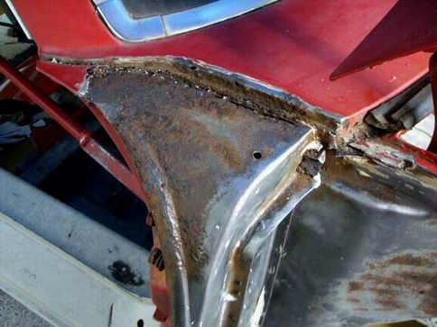
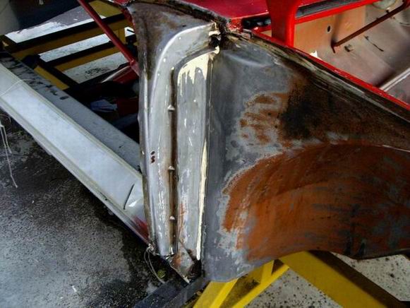
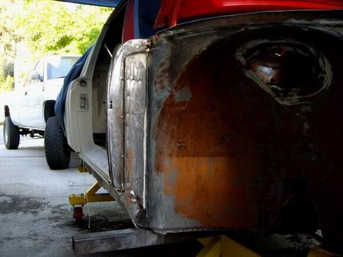
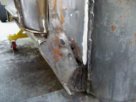
Posted by: Jeff Hail May 16 2008, 12:35 AM
A really good product I have used for years is Jasco metal etch. It's a little different than metal ready. 1st its more agressive and only has to sit about 10 minutes (the instructions says 1 minute and rinse) versus some other products out there. It is very cheap in comparison to others and I think does a better job overall because it is full strength. (3/1, 2/1 with H20 or full strength as I use it right out of the bottle)
This is an excellent etching product. What it does not do ......It is not a conversion coating as it has no zinc or phosphate. If you are repairing and going directly to epoxy primer Jasco is a great product. If you are leaving metal exposed for a period you may get some flash and probably should use a zinc conversion coating even on good clean steel.
I am not fond of conversion coatings because rust is rust no matter what color it turns.
Attached image(s)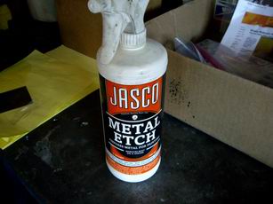
Posted by: craig downs May 16 2008, 12:37 AM
Where can you get it
Posted by: Jeff Hail May 16 2008, 12:40 AM
Where can you get it
OSH, Lowes has it.....haven't seen it at HD.
Posted by: craig downs May 16 2008, 12:54 AM
Thanks
I've never seen it before but I'll go get some and try it.
Posted by: sean_v8_914 May 16 2008, 10:19 AM
Frazee paint store has it too
Posted by: Jeff Hail May 17 2008, 09:13 PM
Cut the dead wood out of the cowl and cowl side extension.
Metal added was done in two pieces as the cowl has a step in it below the fender line. First piece in and then second piece on top just below. The weld becomes the step (really doesnt do anything)
Attached image(s)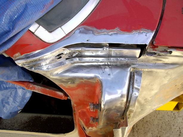
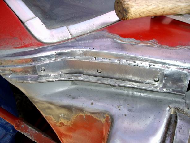
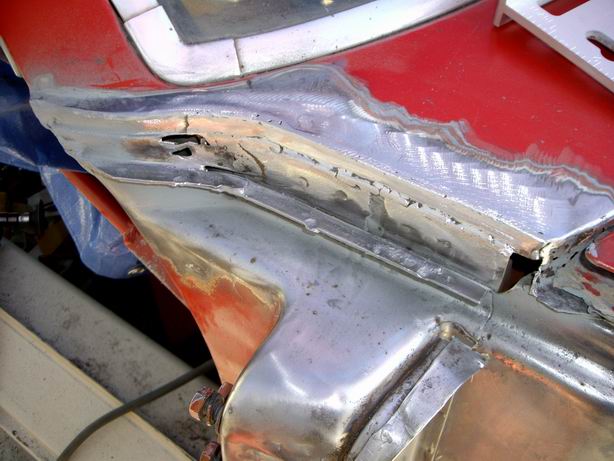
Posted by: Jeff Hail May 17 2008, 09:20 PM
Shaping this area is a tight squeeze in the bends. The front corner of the cowl has a little rust and I will do that separately with the hood off.
Attached image(s)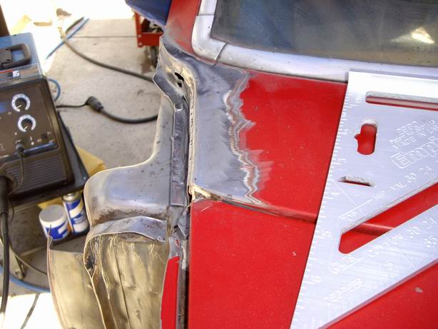
Posted by: Jeff Hail May 17 2008, 09:24 PM
Make a template for the old rusty cowl extension. This is the top curved piece. The closing plate will be made last once everything is fitted.
Attached image(s)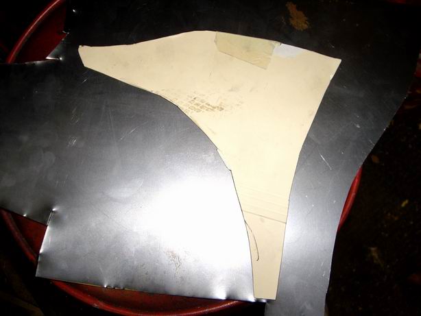
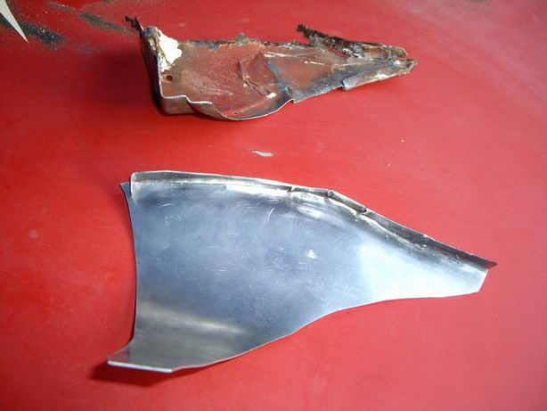
Posted by: Jeff Hail May 17 2008, 09:26 PM
Rough fitting the upper curved extension. Needs a little tweaking at the rear and a flange added.
Until Next time!
Attached image(s)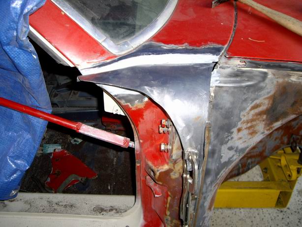
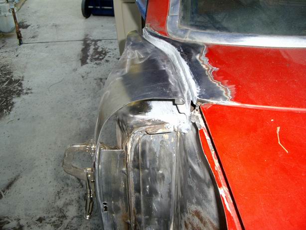
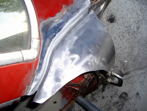
Posted by: Jeff Hail May 26 2008, 01:42 AM
Where was I Eric?
Oh yes.
Finished the passenger side cowl repairs. Also repaired the drain trough and hood seal fence.
Attached image(s)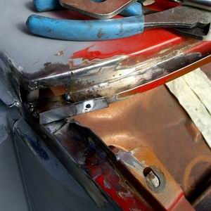
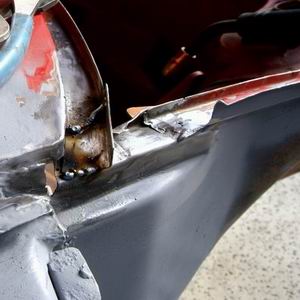
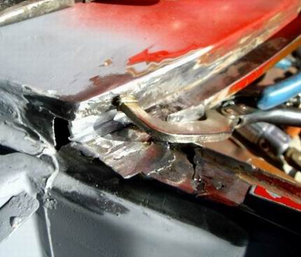
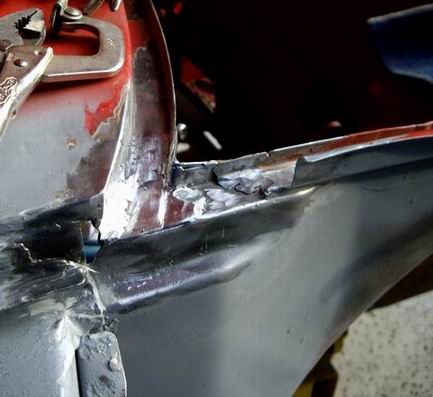
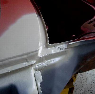
Posted by: Jeff Hail May 26 2008, 01:45 AM
It started raining while I was shooting primer. Not good! Had to sit there with a heat gun to force dry the epoxy primer. Car is covered just do not like to introduce moisture to the equation.
Attached image(s)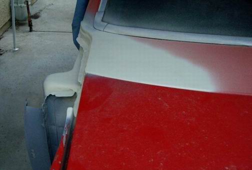
Posted by: Jeff Hail May 31 2008, 10:37 PM
Few things done during the week.
Right front wheelhouse
Attached image(s)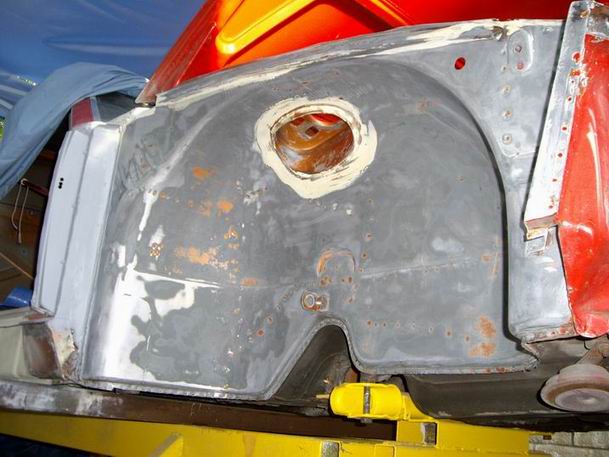
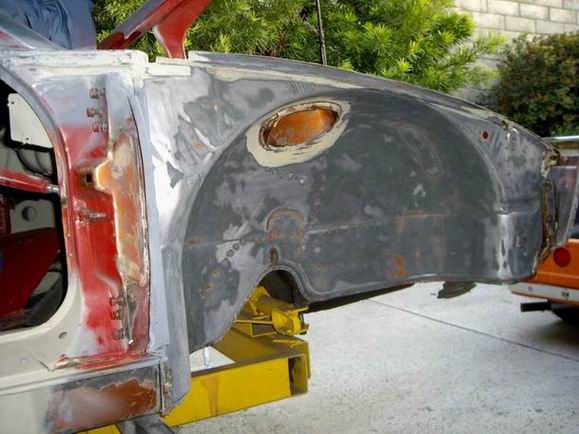
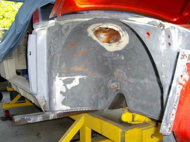
Posted by: Jeff Hail May 31 2008, 10:39 PM
Nothing interesting here. No rust........Primer time.
Attached image(s)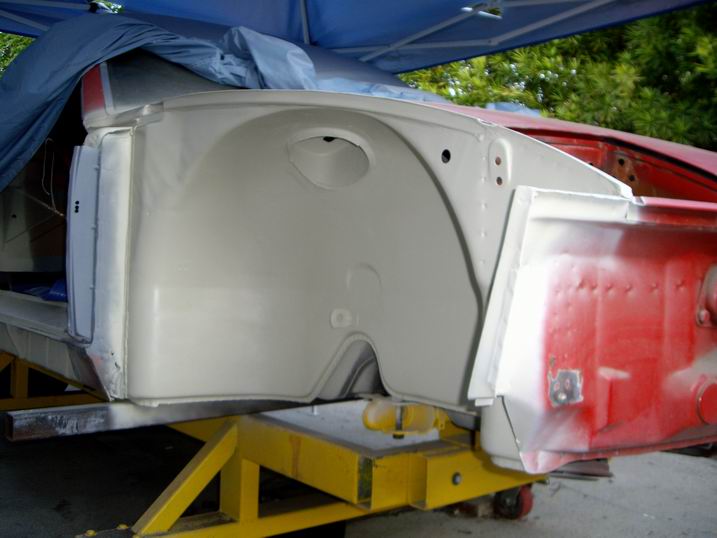
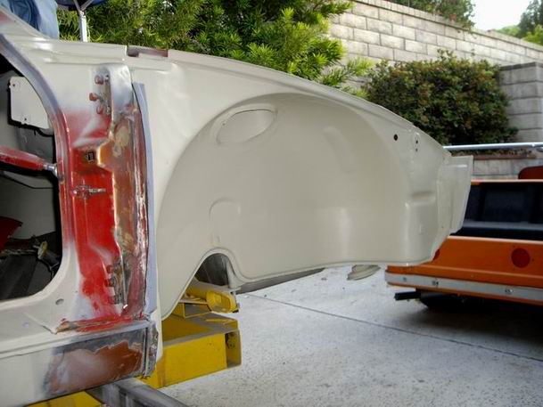
Posted by: Jeff Hail May 31 2008, 10:41 PM
Saturdays business
Front of the right rocker. I actually thought I would find more rust here than thought.
Cut out the old metal and put in some new...
Attached image(s)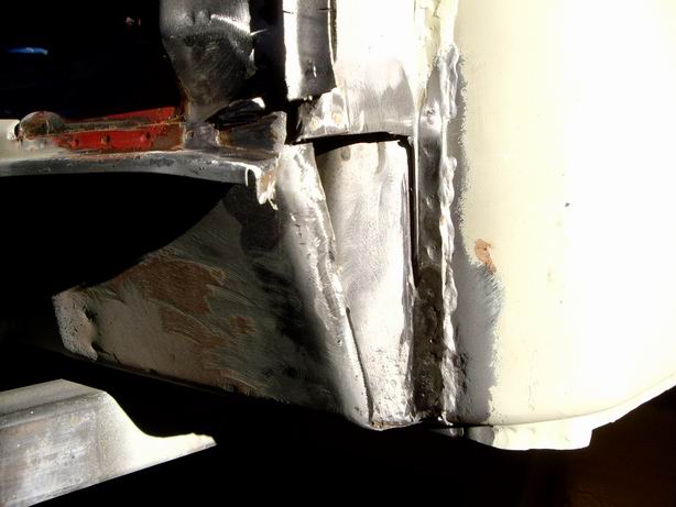
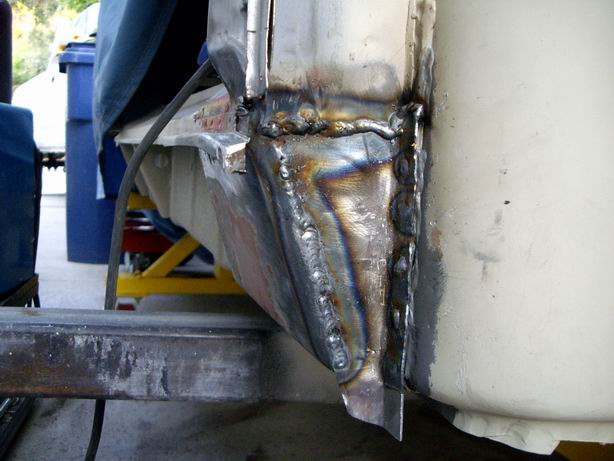
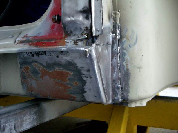
Posted by: Jeff Hail May 31 2008, 10:42 PM
More primer.....
Attached image(s)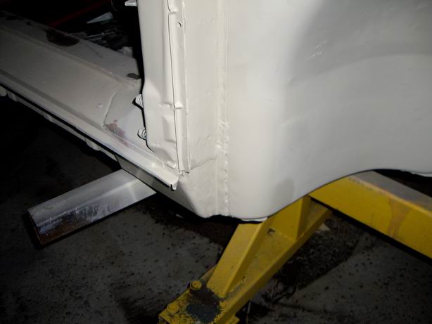
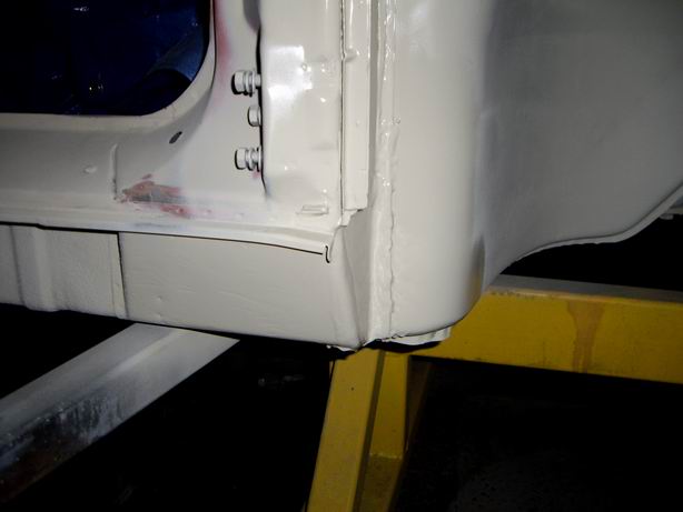
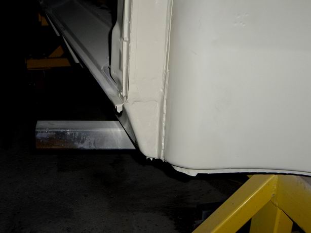
Posted by: Jeff Hail May 31 2008, 10:43 PM
Some porn for Shea!
Attached image(s)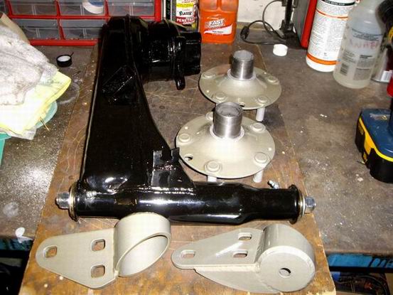
Posted by: Eric_Shea Jun 1 2008, 12:34 PM
Nice...
Posted by: brer Jun 1 2008, 01:00 PM
So, does water drain from the front hood seal trough out through the cowl/fender gap? While looking at mine I wondered if that cowl/fender gap was for water to escape when driving full speed.
Posted by: Jeff Hail Jun 2 2008, 12:32 AM
So, does water drain from the front hood seal trough out through the cowl/fender gap? While looking at mine I wondered if that cowl/fender gap was for water to escape when driving full speed.
Funny you say that. My left side has the outer fench that makes up the trough all the way back to the cowl. Right side had a gap of about 1-1/2 inches. The outer fence is actually part of the fender, the inner fence is made up with the apron.
My first thought is the right fender may have been replaced at one time. After removing all the coatings it was the original fender although a minor repair was done where it meets the door. I think this is where the rust came from. Personally allowing drainage off the side into the fender well is a good idea.
Anyhow I cut the fender off at the fence to repair this area and left the outer fence intact. Wasnt sure where to cut until the next step in body panels is completed.
Which leads to why I cut the fender in the first place....
The next saga in my build is holding to the weight plan. This is one thing I am really trying to not deviate from:
A friend who is the prop industry is letting me use his shop. I obtained the plugs which are an original set of full steel GT fenders that are on loan. You have no idea how hard it was to convince the owner to borrow these in the middle of a high dollar restoration his car is going thru now. The molds we made are done and will lay up the fenders in Kevlar reinforced Carbon fiber using epoxy resin. The Carbon fiber weave is 7 oz which is pretty thick so they will blow away any current fiberlgass part supplier out of the water and also be streetable.
People have asked why I am going this route? First is weight. Second is my cost to make my own GT fenders out of Carbon fiber are about $200 a fender thanks to access to a professional mold making shop. The last reason is all the glass fenders I have seen except for Sheridan are pretty poor quality. This is a bold statement to make but most of the glass part suppliers are getting top dollar for junk that requires so much re-working that I feel is just unacceptable. They are officially on notice now.
I can do better for less.
Posted by: Loser_Cruiser Jun 2 2008, 12:40 AM
so are these a one time deal or are you gonna be taking orders in the future?
Posted by: Jeff Hail Jun 2 2008, 12:43 AM
so are these a one time deal or are you gonna be taking orders in the future?
These are one off's. Sorry!
Posted by: Eric_Shea Jun 2 2008, 08:41 AM
Ohhhhh... you've got them shaking and quaking in their boots now!

Posted by: Jeff Hail Jun 2 2008, 07:50 PM
Ohhhhh... you've got them shaking and quaking in their boots now!
You make me laugh Eric

Posted by: theo Jun 3 2008, 09:24 AM
I have a question about your welding Technique, when you weld in a piece, do you first tack it in then run a steady string of tacks around the seam, or do you run a couple tacks then jump around? Btw your car looks great.
theo
Posted by: Jeff Hail Jun 3 2008, 11:31 AM
I have a question about your welding Technique, when you weld in a piece, do you first tack it in then run a steady string of tacks around the seam, or do you run a couple tacks then jump around? Btw your car looks great.
theo
Welding sheet metal is like Plate Tectonics. For seam welding a patch position and secure the part with tacks. This allows the patch to be adjusted if needed to for a tight fit which is key to a good weld. Then a series of quick trigger pulls to close it up .Sometimes I will get in a hurry and lay a bead. All depends on the part being welded, how it reacts to heat, how thin, cosmetic, structural, gun access etc. Moving around, starting and stopping controls heat at the zone.
Posted by: Gint Jun 3 2008, 09:17 PM
Wait 'til you see him "live".
Posted by: Eric_Shea Jun 3 2008, 10:24 PM
Tip your bartenders and waitresses...
Posted by: Jeff Hail Jun 5 2008, 12:28 AM
Tip your bartenders and waitresses...
Word has it around here you are a class act
 Are you tending bar tonight or the host?
To back up a bit to last weeks intimate conversation. Here are the spacers for using the late Carrera hubs (one inner, one outer on each side of the 914 wheel bearing). Easy enough? Rotors are also Carrera. Depending on going 20mm or 24 mm appropriate caliper half spacers required.
By the way you spelled Carrera incorrectly. Two "R's always come before the single "R". I just wanted to point that out you know. I am sure the bartender or host will volley back with a good jab just for fun. Thats getting back for the Kings Lad thing.
Attached image(s)
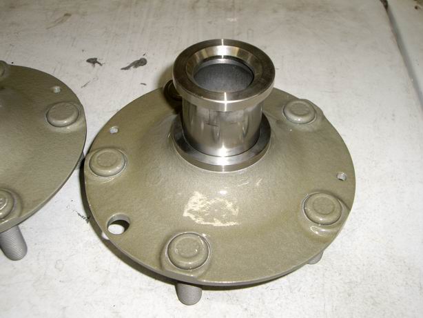
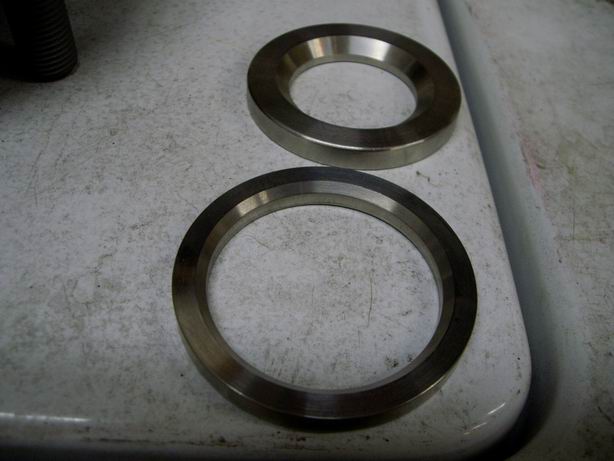
Posted by: Jeff Hail Jun 5 2008, 12:33 AM
For everyone else (except Shea) more instruct'iones (aka specs)
Courtesy of master machinist Mr. Ira Ramin
Attached image(s)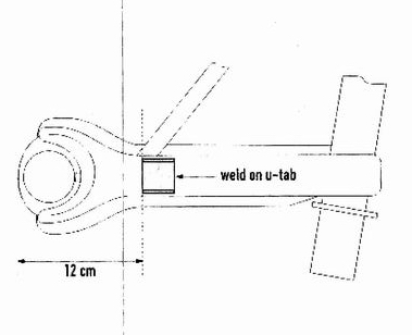
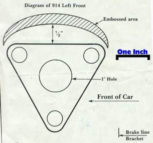
Posted by: Racer Chris Jun 5 2008, 05:01 PM
Hey Jeff,
It was good talking with you yesterday. With a little prodding from Heidi I'm sure I will get your roll cage kit out before the deadline. As I told you - I authorized her to hit me over the head regularly until it is done. Here's what I found this evening when I came back to my desk, lol.
Attached image(s)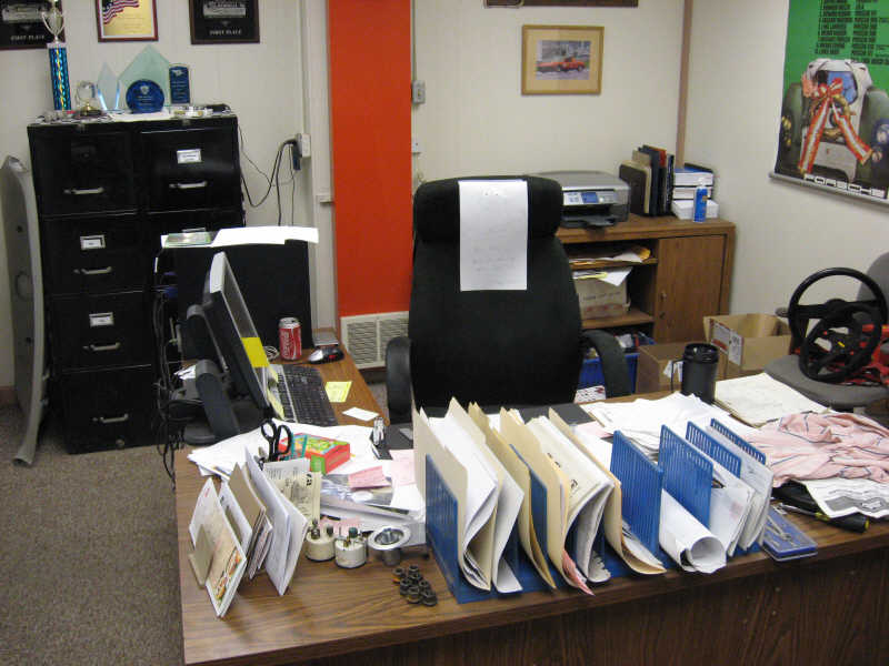
Posted by: Eric_Shea Jun 5 2008, 08:43 PM
 Carrrrrerrrrra...
Posted by: Jeff Hail Jun 5 2008, 09:12 PM
Hey Jeff,
It was good talking with you yesterday. With a little prodding from Heidi I'm sure I will get your roll cage kit out before the deadline. As I told you - I authorized her to hit me over the head regularly until it is done. Here's what I found this evening when I came back to my desk, lol.
Thanks Chris and Hedi,
That rendition is exactly what I actually look like on Sunday mornings.
Posted by: Jeff Hail Jun 5 2008, 09:15 PM
Carrrrrerrrrra... Arrrrgh mate!

Posted by: oh no, not again! Jun 6 2008, 09:47 AM
That rendition is exactly what I actually look like on Sunday mornings.
Jeff- Did I get the nose right??? I'm a stickler for noses....lol
The beatings have commenced!
hehehe

Posted by: Jeff Hail Jun 9 2008, 10:56 PM
That rendition is exactly what I actually look like on Sunday mornings.
Jeff- Did I get the nose right??? I'm a stickler for noses....lol
The beatings have commenced!
hehehe
Close facsimile. Live life through humor and laugh at our foibles I say!!
Just don't beat Chris when he has a firestick in hand. It could get ugly.
Posted by: Jeff Hail Jun 9 2008, 11:25 PM
Speaking about foibles................or sh@t happens.
When Shop Equipment Attacks[u]
Visualize an older media blast cabinet with old seals and 25 pounds of aluminum oxide media decides its time to relocate to another zip code at 100psi?
Yes it did happen and took me 4 hours to clean up the mess today. Aluminum oxide is technically not hazardous but aluminum dust is well quite the pyrotechnic ingredient.
In the middle of this mess my good friend pulls up in the drive way (ironically he blows stuff up for a living in the special effects industry) and see's me with the shop vac cleaning up. He reminds me of the aluminum dust issue and motors that use brushes (spark) and exclaims" no,no, no you need to sweep". Cleanup time doubled. Like I said sh@t happens.
This was supposed to be a week off for vacation and I end up cleaning the garage?
Yeah I know Shea is grinning. Like I said you just have to laugh at stuff. It happens. After the fact I laughed too, especially since I looked like the tin man in the Wizard of Oz wearing a respirator.
Posted by: oh no, not again! Jun 10 2008, 03:16 PM
Just don't beat Chris when he has a firestick in hand. It could get ugly.
No prob, mon!
When you see him with one in his hand, let me know, will ya?
hehehe
Posted by: Eric_Shea Jun 10 2008, 04:17 PM
Ut uh...

I would have kept using the vac. It would have been cool

Posted by: Jeff Hail Jun 13 2008, 12:55 AM
Didn't get much done today.
Fit the Tarett Engineering Anti Sway Bar. Holes measured drill and punch a 1-1/4 inch hole.
The brake line bracket didn't want to leave home peacefully which ended up with a slight wound requiring a quick weld and some grinding.
Measuring and installing the kit only takes about 30 minutes. It took another hour to true the wheelhouse sheetmetal so the bar doesnt bind on the bearing blocks.
If the bar binds the bushings will turn in the bores (not good) and become loose. I don't think I have to say what will happen if the bar doesn't move freely while in operation.
I also added Engmans reinforcement to the wheelhouse. Easy to understand what it's purpose is. A few folks say it doesn't do anything. I disagree. If you know how thin the wheelhouse sheetmetal really is I think it can't hurt.
The bearing blocks must be parallel to each other or the bar will bind and this is the tricky part. Engmans reinforcement helps achive this and keep them parallel.
This section and the sheetmetal directly below the fuel tank cavity are similar to a 911's design yet they are very different. This is an area I feel is a weakness in the 914 compared to the 911 body. The 911 also has it's own inherant weakness as there is no bulkhead between the strut towers. The 911 towers tend to splay open where the 914 also does just not as much. Long story but some homework supports this.
I am contemplating welding a tube from side to side to each nutplate triangle. The bar will ride inside the tube. This will keep the bearing blocks parallel at all times eliminating the what if part? ( I hate what if's when they come later)
Attached image(s)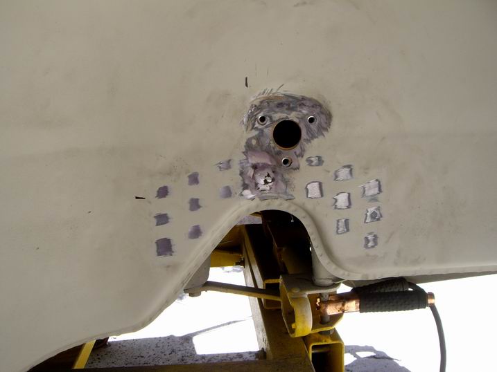
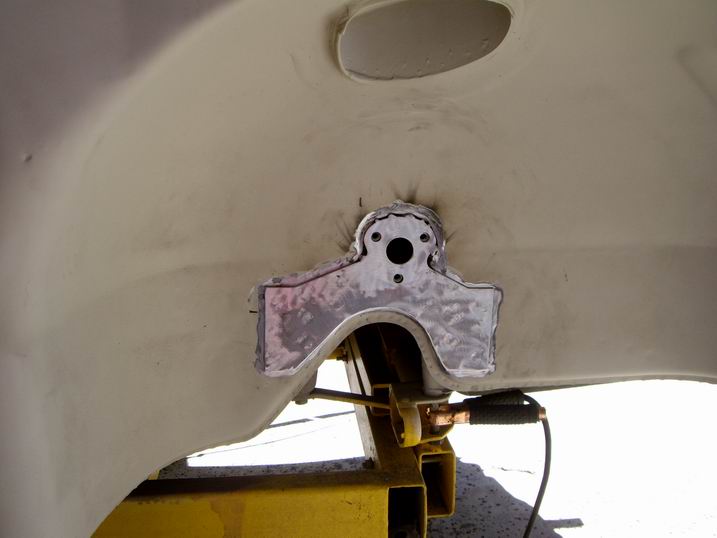
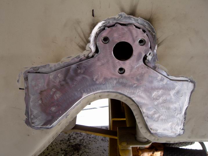
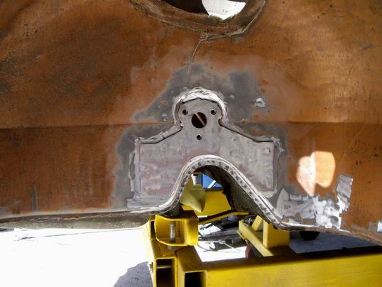
Posted by: Jeff Hail Jun 13 2008, 01:00 AM
After the reinforcements were welded in I used some Wurth Panel Bond Structural Adhesive around the perimeter of the plates. First to seal the edges from any water getting behind them and second to give an aeshtetic blend once they are coated. Third they ain't never going to move ever! (Better Living thru Chemicals)
Once the Structual Adhesive has cured I will smooth the area out with a DA and final coat of primer.
The left wheelhouse still needs the old coating's removed and has two small rust spots at the pinchweld (flash in my book) that need to be addressed before epoxy primer can be applied.
Attached image(s)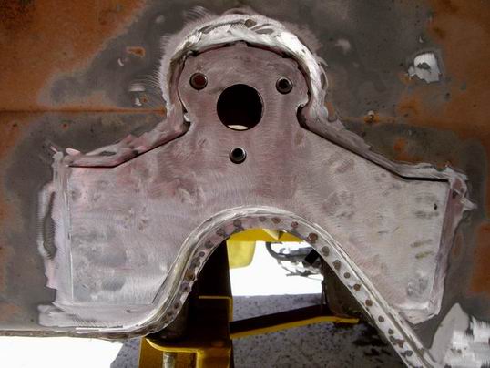
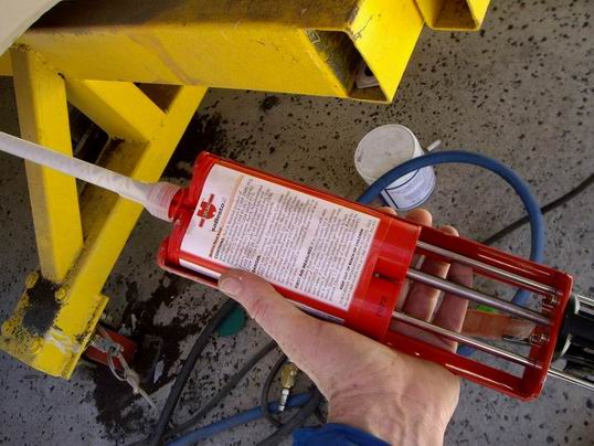
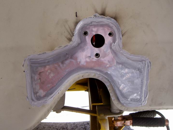
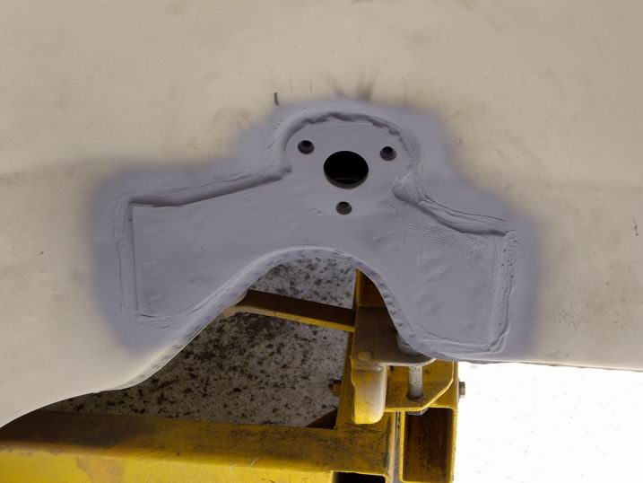
Posted by: Jeff Hail Jun 13 2008, 01:19 AM
While waiting for glue to cure I played with some other parts.
U-Tabs welded to the front control arms and the bushing friction points POLISHED.
Yes POLISHED!
Brake line brackets fabricated, backing plate brackets painted. Rear caliper halves done....The inners are somewhere in Utah. (plug for Shea)
The caliper outers are color matched to Porsche Monoblocks. They are very red but appear very orangish in the photo.
After much thought the inner calipers would be too much a pain in the ass to powdercoat. The area where the e-brake lever pivots doesn't have enough clearance to apply 4-6 mils of powder without rubbing. The inners will be plated by Eric (two plugs for Shea in the same post) because he is THE CALIPER MASTER.
On another note I am envious of Chris Foley. He now has an assistant. I could use an assistant.....couldnt we all? CFR has added Heidi to it's staff who is internet savvy, artistic and from what I hear she has taken control of Chris's shop with an old 914 (thumper) torsion bar to ensure things get done. 
Attached image(s)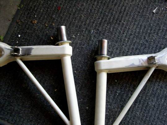
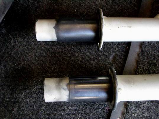
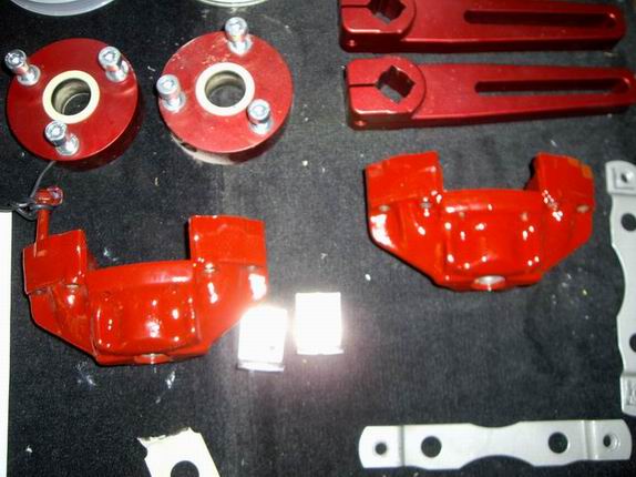
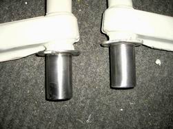
Posted by: Jeff Hail Jun 14 2008, 09:54 PM
Final prep of the reinforcements, one last mockup of the bar and bearing blocks (pivots with finger pressure), weld on the brake line brackets and squirt some primer. Enough for today.
Have a  to attend.....Mine and I am going to do some heavy
and get 

Tomorrow is Father's Day and will be  with pop and will do some more
Until next week..... 
Attached image(s)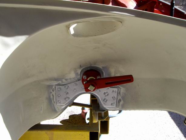
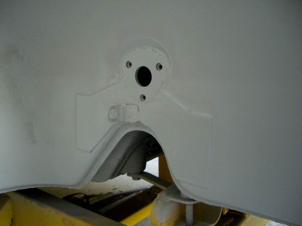
Posted by: Racer Chris Jun 17 2008, 06:40 PM
Heidi's been following me around all day with one of our new Solid Trailing Arm Pivot Shafts in hand. 

So here's a couple pics of today's rollcage progress for you Jeff: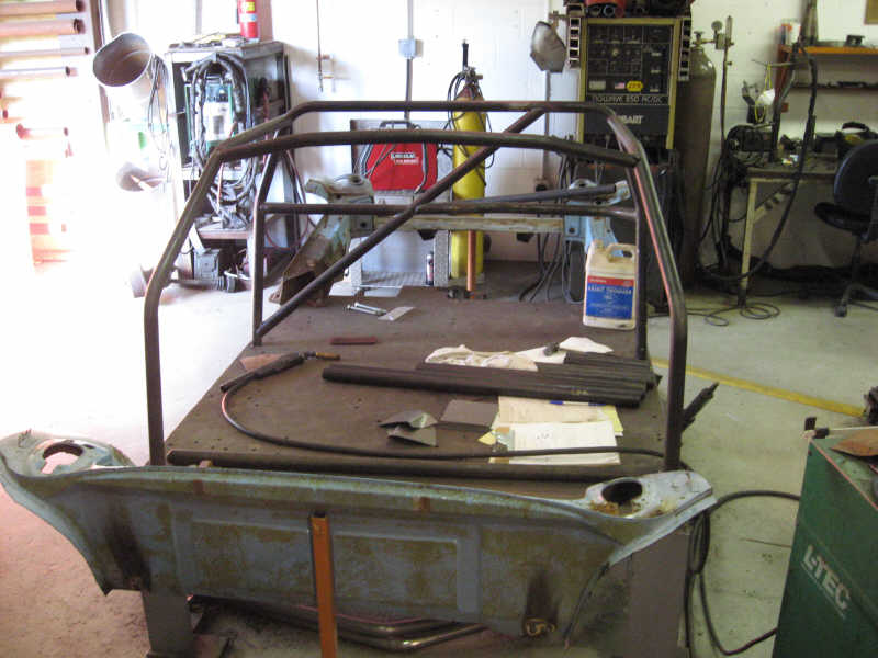
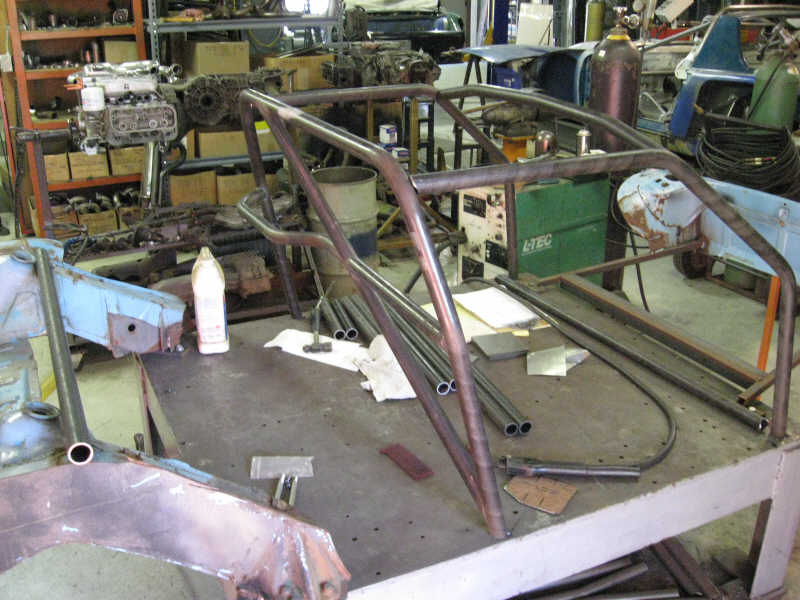
I've gotta go home and tend to my wounds now. 
Posted by: Jeff Hail Jun 17 2008, 08:08 PM
Heidi's been following me around all day with one of our new Solid Trailing Arm Pivot Shafts in hand.
So here's a couple pics of today's rollcage progress for you Jeff:
I've gotta go home and tend to my wounds now.
Awesome! Thats my spec cage.
I like your surface plate with the modified 914 mockup sections. Interesting how you did that. Very flexible system. Post a few more pics once the full mockup is complete for posterity.
Posted by: Eric_Shea Jun 17 2008, 08:40 PM
Happy Belated Birthday Lil'Feller!
Posted by: oh no, not again! Jun 17 2008, 09:19 PM
Hey Jeff- Seems my new "alter-ego avatar" is doing her job well......  all business from now on.....
Posted by: Eric_Shea Jun 17 2008, 10:42 PM
grrrrrrrowl
Posted by: Jeff Hail Jun 17 2008, 11:15 PM
Hey Jeff- Seems my new "alter-ego avatar" is doing her job well......
all business from now on..... Yes she is.... Love it!
(check Chris's email)
Posted by: oh no, not again! Jun 18 2008, 09:50 AM
Hey Jeff- Seems my new "alter-ego avatar" is doing her job well......
all business from now on..... Yes she is.... Love it!
(check Chris's email)
heh, heh, heh.....we need a new emoticon, one craking a whip!
Now get back to work, all of you!!!!!!

Posted by: Racer Chris Jun 18 2008, 11:15 AM
heh, heh, heh.....we need a new emoticon, one craking a whip!
Now get back to work, all of you!!!!!!
![whip[1].gif](style_emoticons/default/whip[1].gif)

Posted by: Jeff Hail Jun 28 2008, 01:10 AM
Well lets see ..................what else could go wrong today?
Received notice that the cage Chris Foley built for me was damaged in transit.
I think Chris and I are going to be optimistic and hope it just fell out of the box. Obviously not Chris's fault. In fact we are both wondering what happened? After all it's a bunch of tubing. What could happen? Did I ever say I think very highly of Chris? Never met the man in person but I just like the guy. He is just a racer kind of guy and does stuff that makes things go faster. That's good enough for me.
Received notice from another shipper that a package has been lost now for 15 days and cannot be located. WTF? How can you lose a package that has tracking numbers all over it and be insured for a bundle? Actually this was a full aluminum engine turned interior for a very important friends Pro-Stock race car that took two weeks to complete.
Today turned into a bummer !!!!!!Aaaahhhhhhhhhhhhhh!!!!!!
The good new's!
At least one package showed up today without a hitch. Inner caliper halves Eric Shea cleaned up for me. Did I ever say I think very highly of Eric? Never met the man in person but I just like the guy. He is just a racer kind of guy and does cool stuff with brakes. That's good enough for me. Listen to Eric as he has words of wisdom when it comes to brakes.
Despite todays downturn of events I had to get away and enter the inner sanctorum for therapuetic purposes.
REAR CALIPERS
BIG brakes while retaining the 914 caliper body and E-Brake with slight modifications. 14 mm spacers....for 24mm Carrera vented rotors. I didn't even fling any C-Clips across the shop! Amazing something went right today. I am calling it the J-Caliper. I bet Shea just eat's that up?
Attached image(s)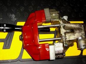
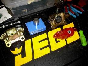
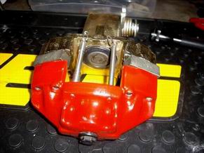
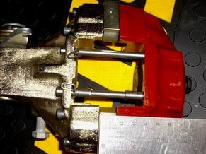
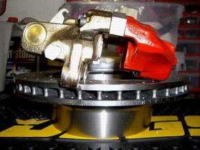
Posted by: KELTY360 Jun 28 2008, 01:25 AM
I look at rust like a diamond in the rough. Rust is afraid of me because it know's it cannot live in my world. Metal becomes submissive because I have confidence in my metal working talents.
Jeff - these bold words were part of your 1st post in this thread. You've certainly proved they are not idle boasts. I've been fascinated by your careful techniques and rigid quality standards.
Given your skills and experience, I'm curious about why you've chosen to invest this much time and energy in a 914? Other than the opportunity to scare lots of rust straight.
Posted by: Jeff Hail Jun 28 2008, 02:46 AM
I look at rust like a diamond in the rough. Rust is afraid of me because it know's it cannot live in my world. Metal becomes submissive because I have confidence in my metal working talents.
Jeff - these bold words were part of your 1st post in this thread. You've certainly proved they are not idle boasts. I've been fascinated by your careful techniques and rigid quality standards.
Given your skills and experience, I'm curious about why you've chosen to invest this much time and energy in a 914? Other than the opportunity to scare lots of rust straight.
Because I can!.........Seriously this build has something special motivating it. Not easy to put words to it. It is what it is. In time everyone watching will see the light. Time is something I have for this one. To most it may seem like a lot of hard work for a car many would have passed on. The high road always has the better view!
In racing every class has a formula to follow. With a big grin I only know how to lead......second place is not an option.
Posted by: Racer Chris Jul 1 2008, 10:19 AM
Well lets see ..................what else could go wrong today?
Received notice that the cage Chris Foley built for me was damaged in transit.
...
I can hardly believe the box made it to the warehouse in Sun Valley and a FedEx worker there decided it had to come back to Connecticut.
I highly doubt the cage was damaged, but I fully expected the cardboard box to get beat up. All the indiviual pieces were strapped to the main hoop assembly with large zip ties to keep them together in the event of a containment breach. Now I won't know until next week what the problem is. It just left Bloomington, CA in a trailer this morning. Maybe if I called there yesterday I could have gotten it to go in the right direction again. Sorry Jeff, I thought I had the shipping details worked out so this sort of problem was unlikely.
Posted by: Jeff Hail Jul 13 2008, 10:59 PM
Let the insanity begin.........
Fender molds completed
1) 1st lay up in 1/2 oz fiberglass mat with epoxy resin and vacuum bagged. (1/16th inch thick buildup) This mat is so thin you can see through it when its wet. All it is for is to make an egg shell form from a conventional lay up of gelcoat, mat and resin (epoxy versus polyester). Let it cure for a few days. Weighs about 1-1/2 lbs. This was also done done to prevent mat print through with the heavy carbon fiber mat used later.
2) Kevlar tape reinforcements bonded in the stone impact zone. Metal backers (stand offs) bonded where the Dzus fasteners mount in all four corners. This will prevent crush and cracks. Metal reinforcement at the rocker molding mounting/ rear lower fender also.
3)One big ass piece of carbon fiber 5-1/2 oz mat. Ended up doing the lay up in 4 pieces. Easier to work with in wetting out the compound curves. The outside will be flawless. The underside will show the mat seams. (who cares)
Technically this type of lay up is cheating (3 stages). First - It insures less heat build up and warpage with the end thickness desired during cure. Have to sand between cured coats with 80 grit to abrade the surface in between laminates. Going this route require's carefull attention between coats to eliminate air pockets. Worth it in the end.
With fiberlgass resin (poly) you can sand it in a few hours. Epoxy is a different bird. It is not as rigid as (poly) which requires wait time until fully cured. More working time is afforded by epoxy resin depending on which hardener is used. I prefer to let cure for at least 24-36 hours. Epoxy resin has many advantages over (poly). It is UV resistant where as poly is not. It will take an impact and flex before it breaks where as poly will crack or rupture.
4) All cured and ready for trimming.
5) The finished product ready for a coat of DuraTec on the exterior.
Attached image(s)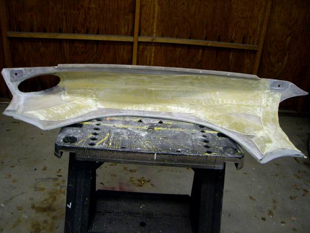
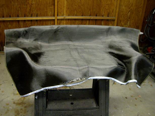
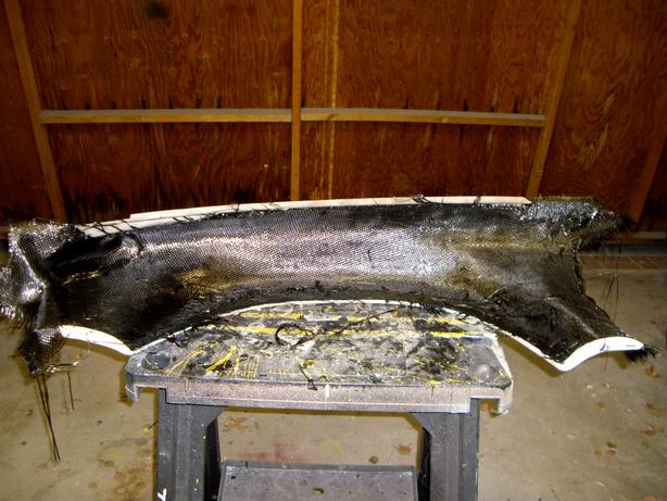
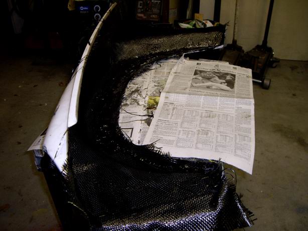
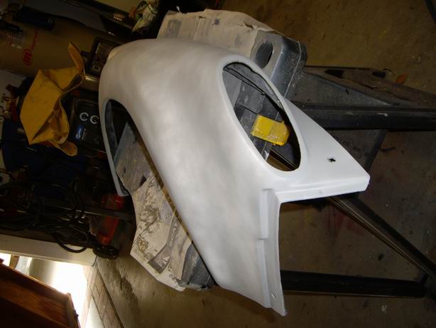
Posted by: Jeff Hail Jul 13 2008, 11:17 PM
Products used for the lay ups and coatings. 60 minute hardener really helps. It will not cure the epoxy resin in 60 minutes but that is when the kickoff time begins. For every 10 degree's over 70 you can deduct 10 minutes. Was 90 so it was perfect. Lots of time to fix things in process before gel time.
Composites are not my specialty but easy to learn and work. Not much different than working fiberglass just different ingredients to bake the cake. I owe credit to my friend who works in the motion picture/ prop industry for assistance in this step of the game especially the molds. I learned a lot. What to and what not to do. The lay up work is very easy. Tooling the molds -well thats a little bit of a challenge.
Some things I learned....Carbon fiber is just like fiberlgass mat. It works and wets the same. In fact I felt it followed curves better. To me the same except a different color. End product is much lighter weight and stronger than fiberglass mat.
Kevlar is another animal. It cannot be sanded or grinded with ease. It will cut with a body saw once cured with epoxy resin but it is extremely abrasive resistant. As long as it has some epoxy over it it can be bonded and re-bonded by sanding the resin. It will not tear or fray. This is a new material to me and has all sorts of potential uses going thru my head now.
Final thickness is 4-5/16. Like any resin it will flow downhill with gravity to the lowest point. Perfect for street use and 3/4 bullit proof!
Attached image(s)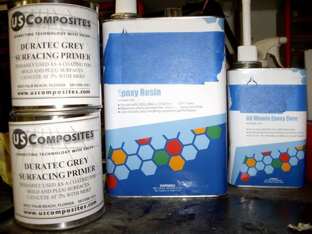
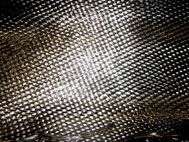
Posted by: Jeff Hail Jul 14 2008, 12:03 AM
By the way Eric glad to see your daughter was ok after the camping incident. As a camper myself I know strange unexpected things comeout of knowhere without warning. Been there with both extreme weather and large animals myself. It can be humbling.
Looked like an exceptional location to pitch a tent. Better weather next time.
Posted by: Eric_Shea Jul 14 2008, 12:14 AM
Thanks Jeff,
Love those newfangled Carerrraa calipers. 
Posted by: Jeff Hail Jul 14 2008, 12:30 AM
Thanks Jeff,
Love those newfangled Carerrraa calipers.
Hindsight. Should have probably gone silver (clear) plating. The Red and Yellow (gold) reminds of a zip code in 90210.
 Oh well. But hey the price was right and will function as intended!
 I am having ARP make the correct 7mm bolts in 12.9 grade for an undisclosed sum. Jimmy got an ear full from me over that. Always best to move forward and that is what I am doing.
Posted by: Jeff Hail Jul 21 2008, 12:01 AM
Busy week. Didn't have any time to get out into the garage.
Finally got a moment late last night (100am) to finish the right front fender and give it a squirt of Duratec. One product I really like using. It covers, it hides, it sticks and anything underneath isnt ever coming through everrrrrrrrr!
Right fender done.
Attached image(s)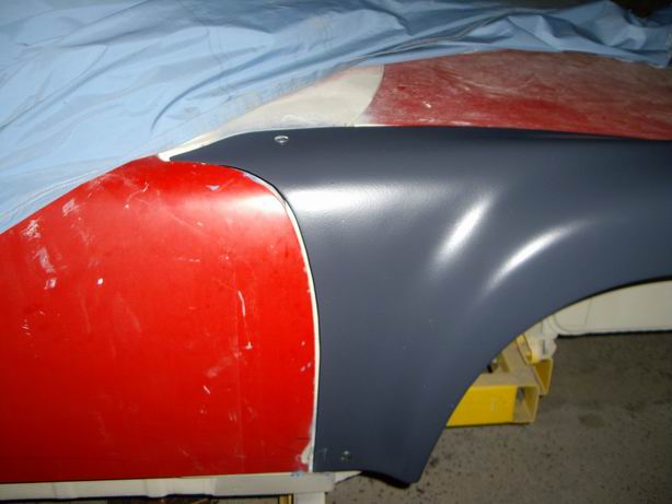
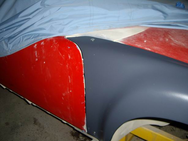
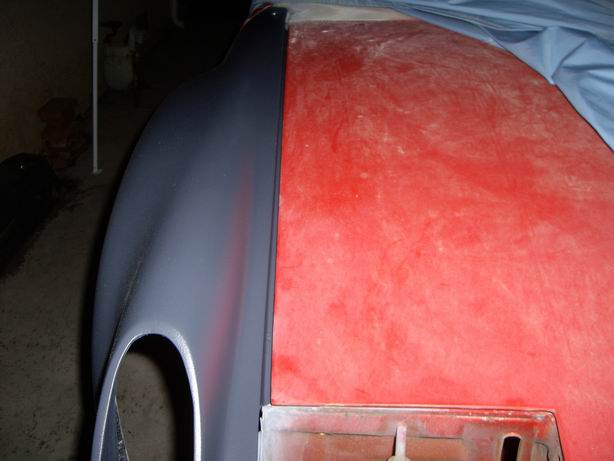
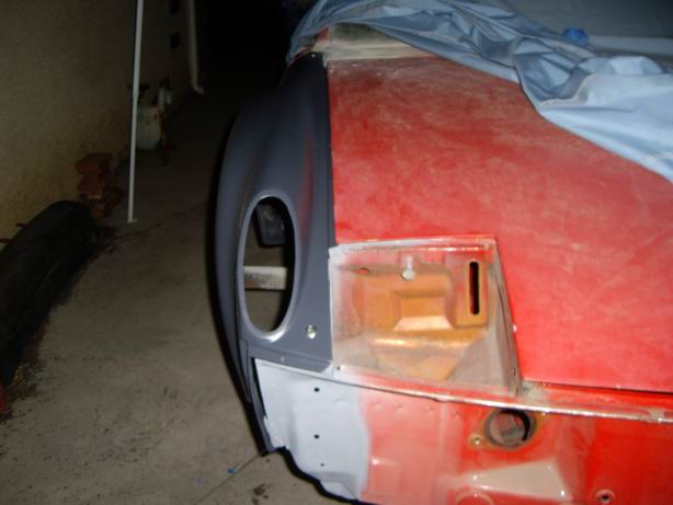
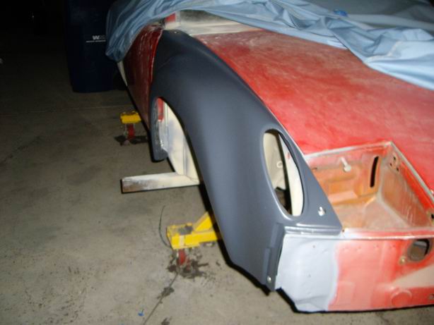
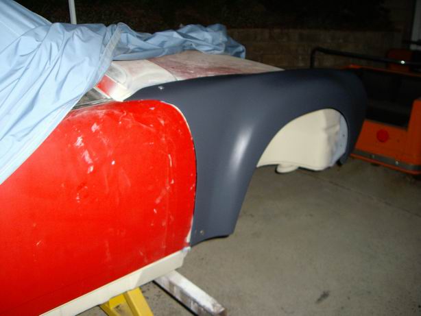
Posted by: Jeff Hail Jul 21 2008, 12:02 AM
Dzus fasteners and mounting plates. I will most likely add a baffle at the rear of the fender to stop road crud from accumulating at the front of the door shell and hinge area. Nice light thin aluminum piece is in mind.
Attached image(s)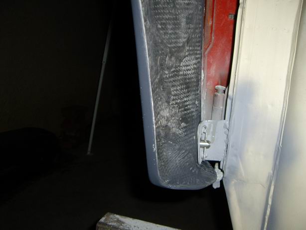

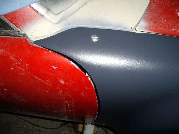
Posted by: Eric_Shea Jul 21 2008, 07:34 AM
Looks slick Amigo. Sure wish you had made an extra set of fenders. You dzus good werk.
Posted by: Todd Enlund Jul 21 2008, 01:40 PM
Man, that is one lucky 914
Posted by: Jeff Hail Aug 8 2008, 12:54 AM
Projects, projects........always a monkey wrench thrown in for good measure somewhere.
One of the projects formula was I had to retain the stock rear calipers and use spacers for the wide Carrera rear rotors. (to retain the E-brake) Spacers easy. Fasteners not so easy. I could have used Grade 10 1/4x28 bolts but I did not feel the safety factor of 20% was there. I researched and contacted Verbus. They provided the specs for the original 914 caliper bolts and confirmed my research that Grade 10 did not provide the safety/ failure factor I required. Verbus also does not make a longer caliper half/bolt in 12.9 grade. No one makes an off the shelf bolt this length.
Guess what no one including Multi-Specialty-Metric fasteners had the M7 bolts that would survive hell and back with a 20% safety factor. I learned long ago do not sacrifice or compromise anything when it comes to brakes and hardware. First rule in racing is you can only go as fast as you can stop.
I called an old aquaintance to the challenge. Gary at ARP (Automotive Racing Products). Through the "specialty department" I worked with Jay in manufacturing custom M7 fasteners that would even exceed the 8mm bolts used on the 911 Carrera calipers. 190Ksi caliper bolts with 12 point heads. Unobtainium!
Cost was startling but I did not have much choice. Still a bargain when you compare to a ready set of 914/6 calipers.
These fasteners come into "unobtainium" category when you look at the tensile strength specs. Far exceeding the 20% safety factor and the extra 14 mm in width will not flex or break. Money well spent.
Attached thumbnail(s)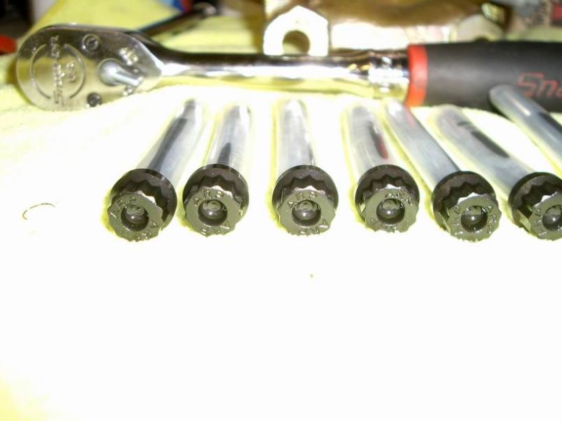
Attached image(s)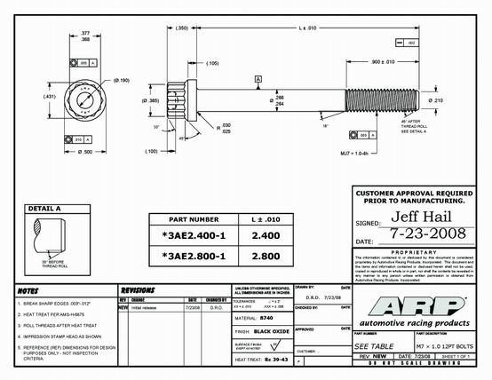
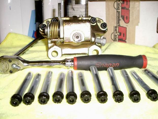
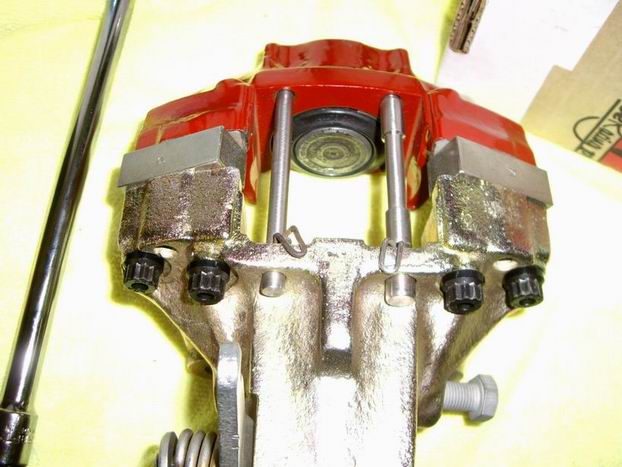
Posted by: Wes V Aug 8 2008, 10:53 AM
Jeff;
Couldn't ARP have done it with studs and nuts with hardened washers. It sure would have been easier to manufacture.
Wes V
Posted by: Jeff Hail Aug 8 2008, 01:18 PM
Jeff;
Couldn't ARP have done it with studs and nuts with hardened washers. It sure would have been easier to manufacture.
Wes V
The length was an issue as strength diminishes with length. 8mm was not an option as the calipers do not have enough meat to drill out. The strength is based on the diameter ,grip area and length of the fasteners. Longer bolts (through), washers and nuts were not recommended with the heat span calipers are subject to. Growth and contraction with heat affect dimensions. This possibly could result in the caliper halfs shifting ever so slightly which could result in fluid seepage between the halfs. Studs were considered but would have still had "play" because the outer half would still need to be drilled to 7mm.
12.9 and higher grade fasteners require a 90% proof rating. In plain english when you torque the fasteners properly a given amount of stretch occurs. Grade 12.9 bolts are tightened right up to their 90% proof load. There is no other effective way to tighten a grade 12.9 bolt. Grade 12.9 bolts do not work effectively with spring washers or shakeproof washers. These don't bite into the hardened surface of the bolt.
Posted by: Eric_Shea Aug 8 2008, 06:26 PM
So... ARP makes the fasteners. Red Green supplied the spacers.
I just finished a set of Carera rear calipers with the "honk'n" spacers (not as sexy as your's mind you...) and the Verbus M7 hardware was (I think) 65 and 70mm. No workie?
Damn  I just mailed them out this AM and I could have checked.
Fasteners look slick Mr.
Posted by: Jeff Hail Aug 8 2008, 07:49 PM
So... ARP makes the fasteners. Red Green supplied the spacers.
I just finished a set of Carera
rear calipers with the "honk'n" spacers (not as sexy as your's mind you...) and the Verbus M7 hardware was (I think) 65 and 70mm. No workie? Damn
I just mailed them out this AM and I could have checked.Fasteners look slick Mr.
Funny thing is M7 hardware is found all over the world on cars, bikes everwhere. Just cant find replacements in these lengths in the aftermarket.
Your measurements are correct 65,70mm -why did they not work?. Bet they were 8's huh?
I thought the Carrera bolts were 8mm? Actually I think the early one's were 7mm.
Fronts were 8 for sure....maybe....ok I admit not sure on the early's.
 The lates pretty damn sure though.
 Never dealt with Red. Wasn't he the guy from "The Taking of Pelum One Two Three" back in 1974?

Posted by: Jeff Hail Aug 8 2008, 07:55 PM
Haven't worked on the tub in a few weeks. Now I can get back to my regular programming.
Then today my friend Chris sends me this. Have a feeling I am going to get sidetracked helping out.
Attached image(s)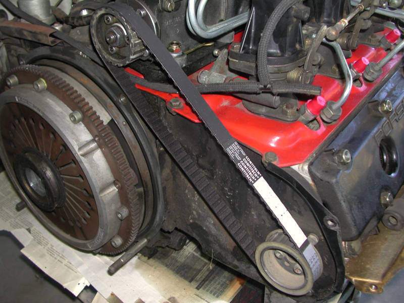
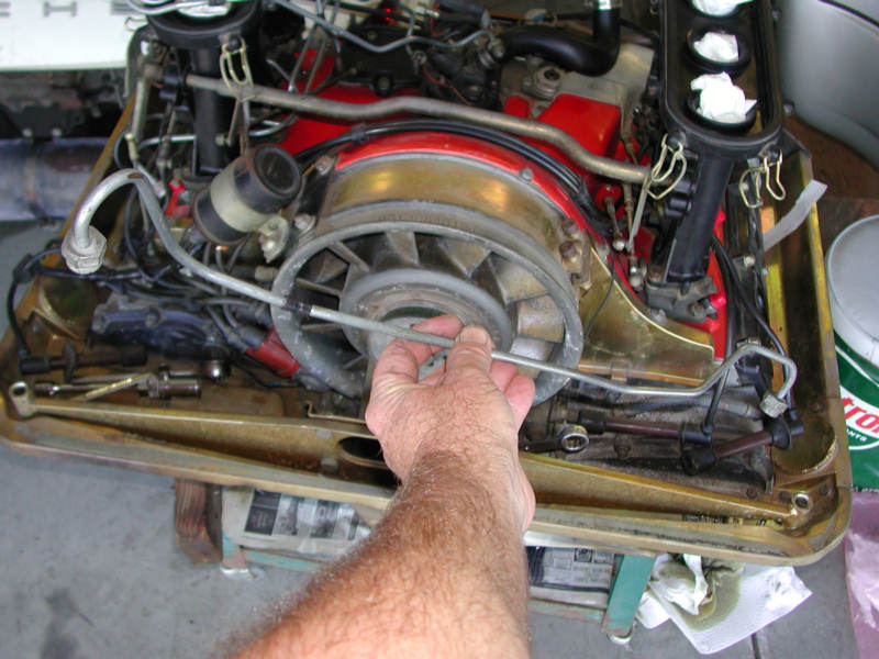
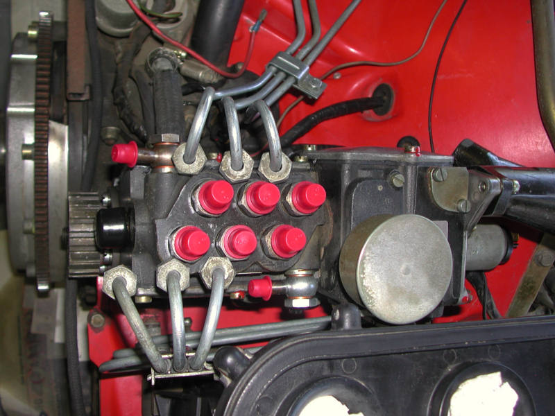
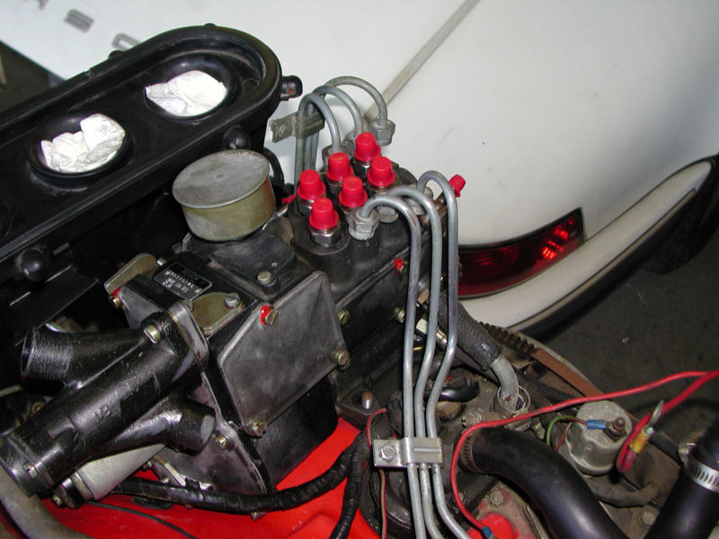
Posted by: Eric_Shea Aug 8 2008, 08:23 PM
No, they worked fine for me. I was asking why they wouldn't have worked for you. It seems it would be less expensive to pick up a core pair of rear Carrera calipers and steal the fasteners.
I'm fairly certain all rear Carrera calipers are M7. The set I rebuilt had the 65 and 70mm M7... I really can't recall if they were Ribe or Verbus. The funny thing with M7 stuff on Porsche calipers is they are both Verbus and Ribe on the same caliper. Ribe made the longer fasteners on the 914 front caliper and Verbus made the shorter ones. Maybe this is why Verbus didn't have anything listed...
Ribe is listed at 12.9 and Verbus is 11.9
Posted by: Jeff Hail Aug 8 2008, 10:04 PM
No, they worked fine for me. I was asking why they wouldn't have worked for you. It seems it would be less expensive to pick up a core pair of rear Carrera calipers and steal the fasteners.
I'm fairly certain all rear Carrera calipers are M7. The set I rebuilt had the 65 and 70mm M7... I really can't recall if they were Ribe or Verbus. The funny thing with M7 stuff on Porsche calipers is they are both Verbus and Ribe on the same caliper. Ribe made the longer fasteners on the 914 front caliper and Verbus made the shorter ones. Maybe this is why Verbus didn't have anything listed...
Ribe is listed at 12.9 and Verbus is 11.9
The original Verbus I pulled off was 12.9 on all. One concern was when they are proofed (torqued to 90%) they really arent supposed to be reused over and over. I doubt I would ever have a problem but don't want to find out.
Posted by: Jeff Hail Aug 9 2008, 08:46 PM
Back to the regular program.........
Stripped the nose and primed today.
3rd pic shows driver side cowl with a bit of rust in the usual place.
Attached image(s)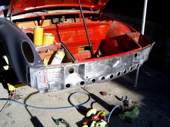
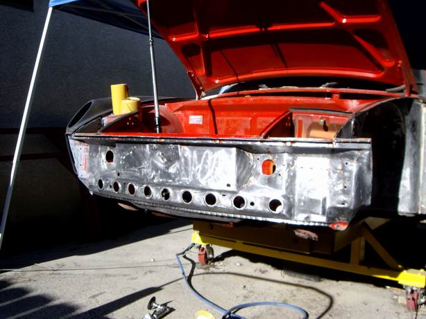
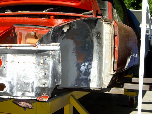
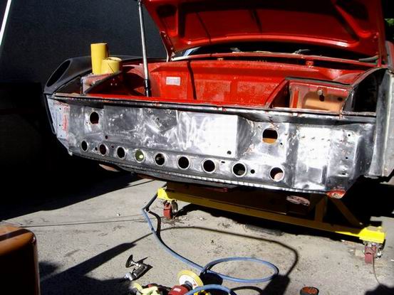
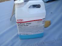
Posted by: Jeff Hail Aug 9 2008, 08:47 PM
Easy day
Attached image(s)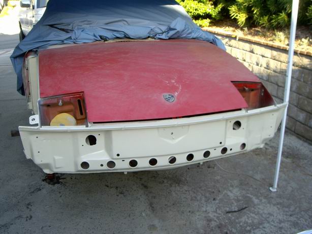
Posted by: KELTY360 Aug 9 2008, 08:58 PM
Haven't worked on the tub in a few weeks. Now I can get back to my regular programming.
Then today my friend Chris sends me this. Have a feeling I am going to get sidetracked helping out.
So when does the engine go back in the Mulholland RSR?
Posted by: plymouth37 Aug 9 2008, 09:48 PM
My god those fenders are fricken amazing! How much for a set, serously I need those, where should I send the check?
You are going into production with these whether you like it or not!
Posted by: Jeff Hail Aug 9 2008, 10:15 PM
Haven't worked on the tub in a few weeks. Now I can get back to my regular programming.
Then today my friend Chris sends me this. Have a feeling I am going to get sidetracked helping out.
So when does the engine go back in the Mulholland RSR?
When my phone rings?
Posted by: Jeff Hail Aug 9 2008, 10:53 PM
My god those fenders are fricken amazing! How much for a set, serously I need those, where should I send the check?
You are going into production with these whether you like it or not!
Lot of time to make them Dana. I did make 4, other 2 are in storage as spares- I hope I will never need them. Believe me I thought about making a run but they were very time intensive to do. The last two I pulled in a big hurry and distroyed both molds in the process. No kidding.
I will be doing a set of 12 inch rear flares in c/f soon. These will be tricky as I have no plug to pull a mold from. I have a few ideas though
....running around this head of mine. By the way nice project you are doing. You have impressive skills.
Posted by: Jeff Hail Aug 20 2008, 09:11 AM
Fitting the front structure. Just tacked so I can square all the pieces during the mockup.
Fit of the pieces is perfect considering it began as an email and photo in California and fabbed in Conneticuit (by Chris Foley). Chris's work is first rate.
All ties into the lower control arm and suspension crossmember control points at the same time triangulating the nose and cowl. Very light weight.
Hey Chris think the headlight motors are going to fit?
Attached image(s)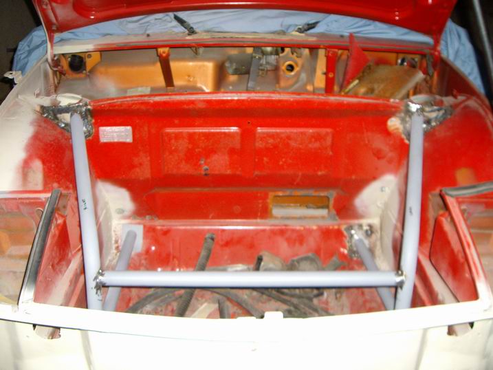
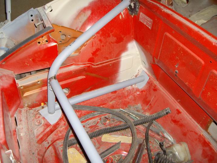
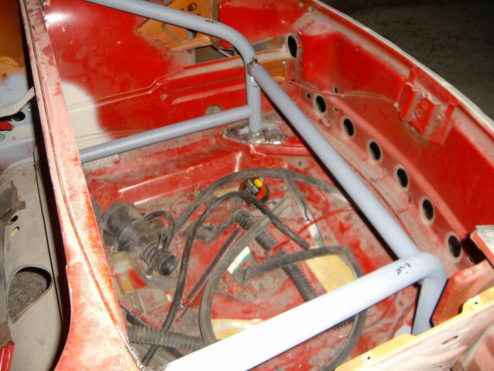
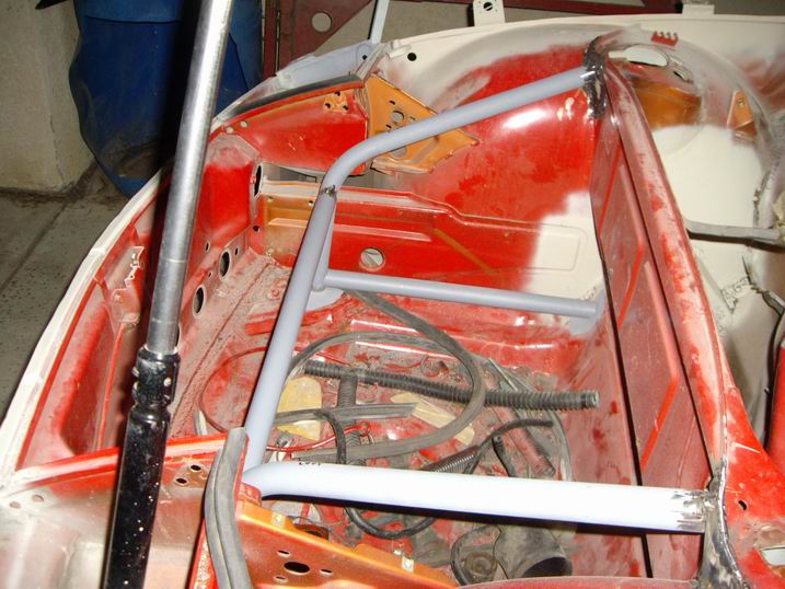
Posted by: Eric_Shea Aug 20 2008, 09:25 AM
Looking great Jeff. Is a GT shroud going to fit in there? Are those bottom pieces going to tie into the crossbar somehow?
I've been wanting to do the same bracing up front but I haven't been able to figure out a way around the oil lines on the left and the fuel pump on the right. Looks like your design would clear the fuel pump though.
Posted by: Jeff Hail Aug 20 2008, 10:02 AM
Looking great Jeff. Is a GT shroud going to fit in there? Are those bottom pieces going to tie into the crossbar somehow?
I've been wanting to do the same bracing up front but I haven't been able to figure out a way around the oil lines on the left and the fuel pump on the right. Looks like your design would clear the fuel pump though.
The lower base plates at the bulkhead attach directly on the opposite side of the suspension crossmember mounts. Those will get reinforced also inside the tunnel spreading the load area out further.
Gt shroud? Nope! Have something else in mind.
Posted by: Jeff Hail Aug 30 2008, 08:02 PM
Have not had much time to play. Day job busy. Helping others with projects. Like they say nice guys finish last!
The passenger side of the car is officially completed (minus RR flare which is will be done soon in CF).
Today I finished all the mounts for the right side front fender. Added the two remaining Dzus fasteners on top. Little things take time. Done!
All the mount brackets on the underside also have backing plates bonded to the fender itself so it does not crush or crack.
Attached image(s)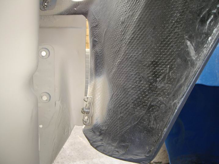
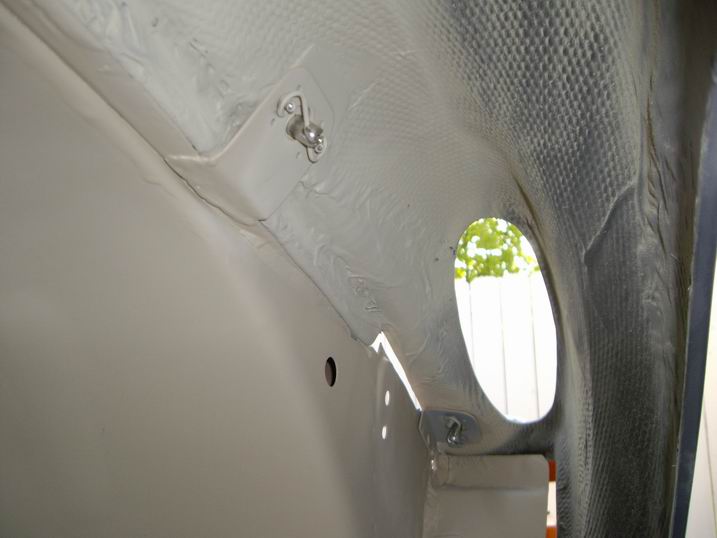
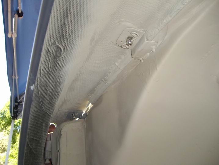
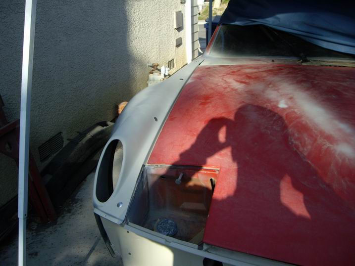
Posted by: Jeff Hail Aug 30 2008, 08:05 PM
Finished up the front structure.
It is still only tacked at the base plates but all the tube to tube joints are welded.
I need to cut the tacks and work on the right side front control arm mount bracket. (it has a minor issue to address)
Attached image(s)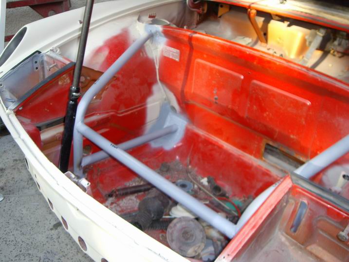
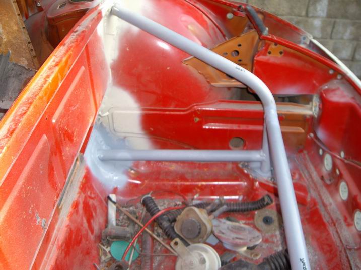
Posted by: Racer Chris Aug 31 2008, 05:45 AM
Looks good Jeff!
Eric, a gt cooler shroud would fit fine. The tubular structure is wider and higher than the f/g piece.
Posted by: Rocket Man Sep 5 2008, 08:20 PM
Jeff,
Awesome work and great thread… you have inspired me.
I have a couple of questions to help me determine where to re-start on my garage queen teener.
1. Where did you find the factory tolerance info on the starting page of your thread, quoted below?
“Keep in mind that tolerances for the 914 were 7-9mm from the factory so anything you can do to make it better is worth it.”
Is this info documented anywhere, and do the tolerances include door gaps and hood-fender gaps?
My rear trunk lid to fender gap gets wider on both sides going from the back to the front…I suspect it could be from a questionable fender flaring process from the PO.
2. Is there a preferred way to remove/separate parts that have previously been seam welded rather than spot welded together, such as a previously replaced battery box or front fender, without damaging either the part being removed, or the part it is removed from? A battery box is not so valuable, but a front fender is. I want to remove and re-use the fender, and do it right, unlike the PO.
Thanks, and keep your progress updates coming.
Posted by: Eric_Shea Sep 5 2008, 08:58 PM
That's what I was thinking. There might be hope for a suspension tie-in for me yet.
Posted by: Jeff Hail Sep 12 2008, 02:44 PM

Attached image(s)
Posted by: r_towle Sep 12 2008, 02:49 PM
What did Jeff do this week???
Inquiring minds want to SEE
Rich
Posted by: Jeff Hail Sep 13 2008, 09:00 PM
What did Jeff do this week???
Inquiring minds want to SEE
Rich
CF+EPR= REAR FLARES DONE
No showy yet. Just pulled from the molds.
Posted by: Jeff Hail Sep 13 2008, 09:03 PM
Bits and pieces done today.
Repaired and sectioned a piece at bottom of the front wheelhouse.
Crap I couldnt even find the seam when I was done.
Closed the antenna wire hole. I swear that had one purpose! To leak!
Just had to stick my finger in the wet primer. Nope not dry yet!
Attached image(s)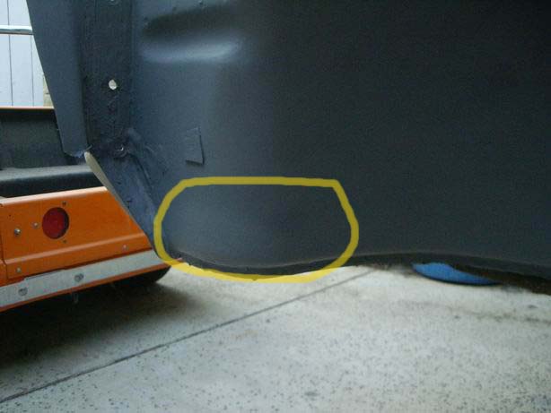
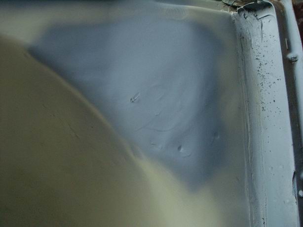
Posted by: Jeff Hail Sep 13 2008, 09:05 PM
Lower left front wheelhouse. Not bad. Little piece to replace.
Attached image(s)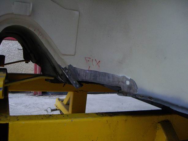
Posted by: Jeff Hail Sep 13 2008, 09:17 PM
Front left floor is not as bad as I first thought. The pedal base is all good steel.
Just to the left where I cut the dead foot out is easily repaired.
Attached image(s)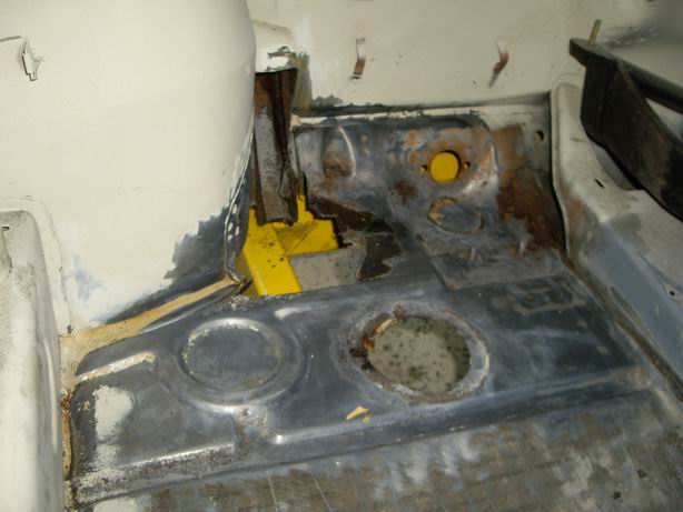
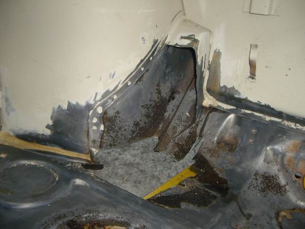
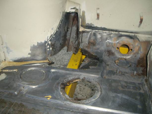
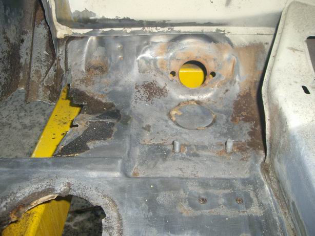
Posted by: Jeff Hail Sep 13 2008, 09:38 PM
One thing I did notice is two cracks in the sheetmetal where the suspension crossmember hump is. I saw these from underneath the body. This required removal of the dead foot to access the area. The cracks are clean and appear to be from the forming process not stress.
When sheetmetal is formed in a die the edges/bends need to be smooth or polished otherwise the metal will not draw smoothly and thin out at the bend. Wax or lube used during the forming process also helps a lot. This will eventually split open.
Any of you guys who reload will understand. Try sizing a case without lube.
I will need to media blast this area clean. Fab the pieces and as Shea would say "do that welding thing I do".
Water entry did not help this area. Although that came from the cowl above.
Surprisingly the steel is in good condition with the exception of what I cut out.
Attached image(s)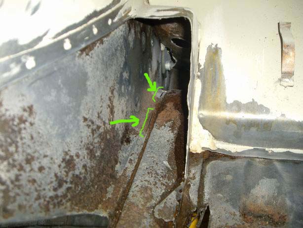
Posted by: Jeff Hail Sep 18 2008, 12:57 AM
Cut and trimmed the front floor footwell. Media blasted the surface flash.
Easier to do the repair in two pieces (actually 3)
The piece just to the left of the pedal box is an easy part to make. Just a rectangle cut to size and burn it in.
Attached image(s)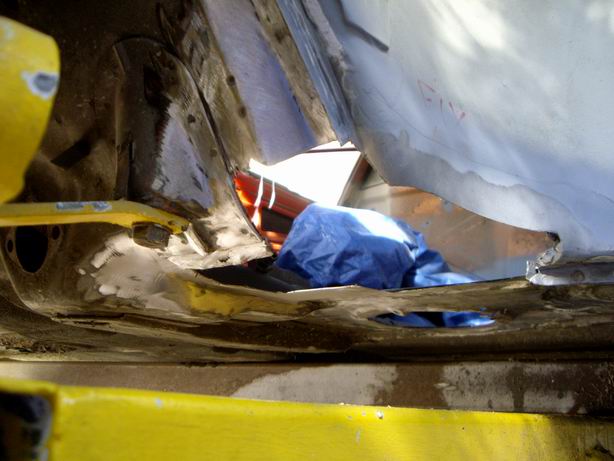
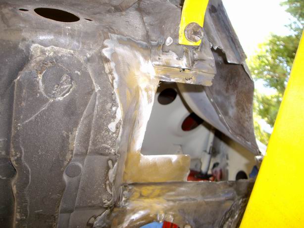
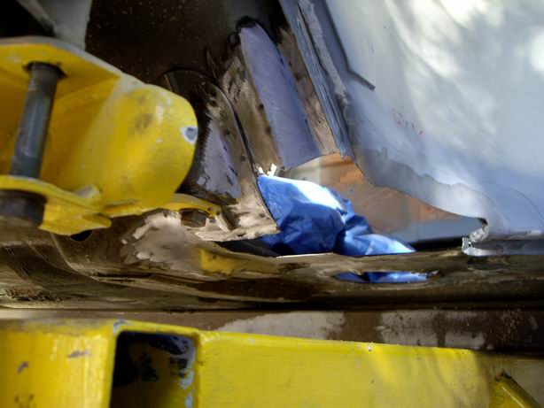
Posted by: Jeff Hail Sep 18 2008, 12:59 AM
The second piece to the left of that took some "beating". My beating bag of choice.
Attached image(s)
Posted by: Jeff Hail Sep 18 2008, 01:01 AM
Cut the template
Attached image(s)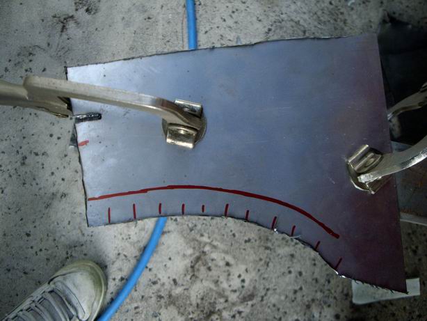
Posted by: Jeff Hail Sep 18 2008, 01:02 AM
Piece #1 clamped and ready for fire.
Attached image(s)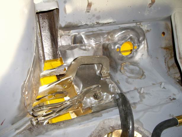
Posted by: Jeff Hail Sep 18 2008, 01:04 AM
Piece #2
Attached image(s)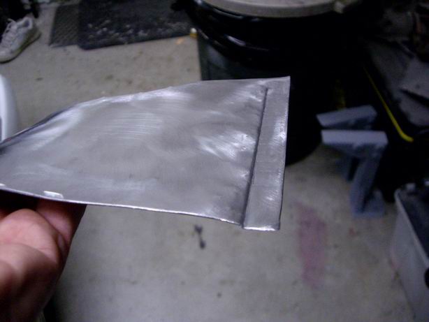
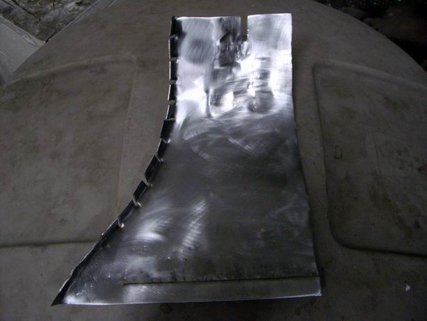
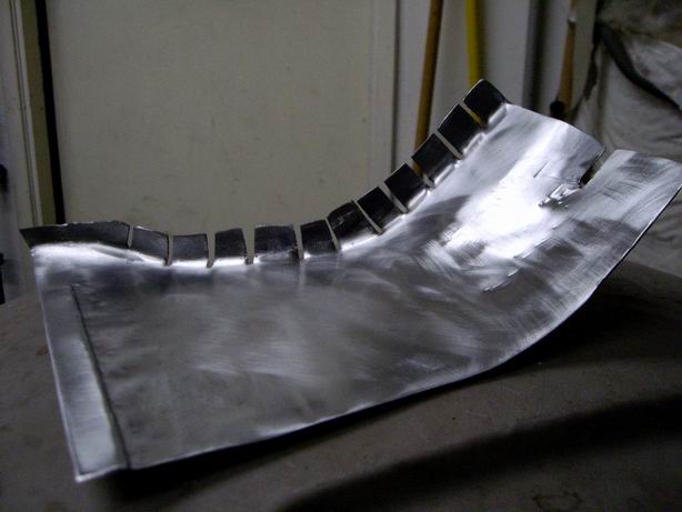
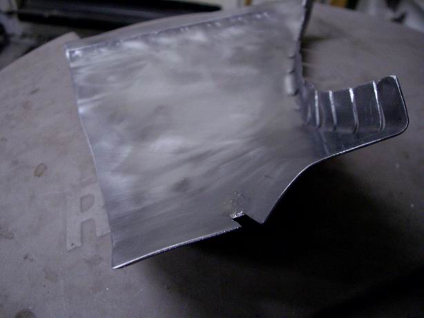
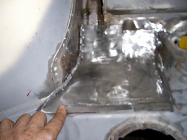
Posted by: Jeff Hail Sep 18 2008, 01:07 AM
Ran out of daylite. Piece #2 will be burned on Thursday.
Attached image(s)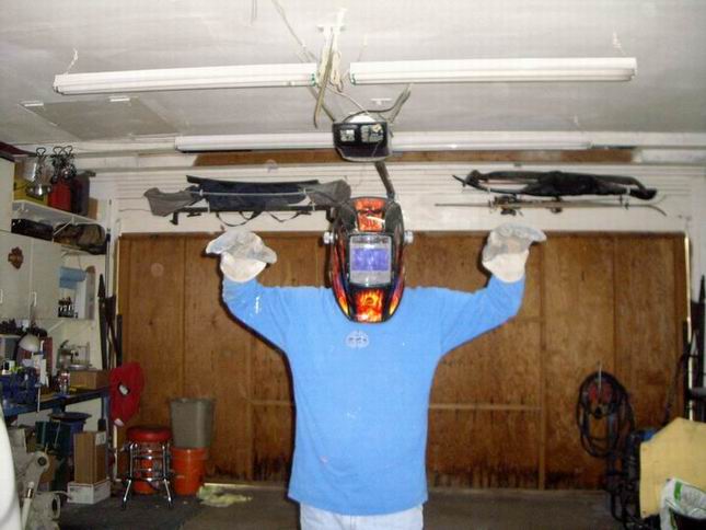
Posted by: Jeff Hail Sep 19 2008, 06:02 PM
OBJECTS MAY APPEAR CLOSER THAN THEY APPEAR
Nice 914 on the 5 Fwy at Valencia Blvd today
Attached image(s)
Posted by: Jeff Hail Sep 23 2008, 09:26 PM
Not bad...
Attached image(s)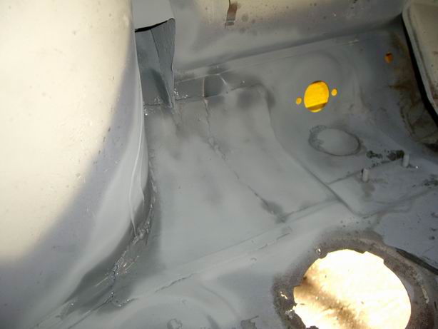
Posted by: Twystd1 Sep 23 2008, 10:35 PM
Jeff.
You gunna be at your house next weekend?
And do you need any help for a few hours?
Clayton
Posted by: Jeff Hail Sep 24 2008, 12:59 AM
Jeff.
You gunna be at your house next weekend?
And do you need any help for a few hours?
Clayton
Long time no hear Clayton! Glad to know you are still lurking in the shadows. I hope all is well my friend. How is the beach life these days? I'm in cruise mode right now. Can't say I will be home or not. You never know?
(Post edited due to foresight)
Posted by: Jeff Hail Sep 30 2008, 09:55 PM
This evenings fabrication.
pedal board support to replace the old rusted one I cut out.
Attached image(s)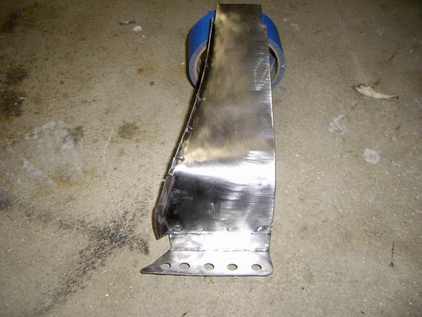
Posted by: Twystd1 Sep 30 2008, 10:39 PM
Hi Jeff.
I was just looking at the ground control shocks setup that BradHolio said he could hook me up with.
It cost about 2K for that particular setup for all four corners..
Do you have a sense of waht are you going to run for bars, springs and shocks? (Brands, etc)
AND... Since I'm tearing into the body work and minor suspension mods. What would you do if you were going to throw some bucks at the chassis?
The Engman long kit is a must as well as the sway bar braces. What else would suggest for a flared car with 7s and 8s stickys for the street and occasional A/X?
What bracing can I do while the car is apart that creates enough rigidity and still be streetable and affordable? I am thinking a 4 point cage with a down bar that attatches right below the door hinges and goes back to the sill/long area next to the trunk release.
6 points actually.
My fear is transferring to much flex to the wheel house and front end. As they are basically stock.
I dunno... I just want to hear what you might do for a street and occasional AX car?
Note. At the proper time and the proper place........
I drive the streets like it's a track. I have all my life.
Thus it is necessary to make this car work without snapping suspension pieces because I am a middle aged nut case.
I believe I can build dam near anything given the time and money..
It just doesn't look ANYTHING like your work. I wish I had your mad skilzzzz.
By the way. I have 3 new in box intercoolers. Ya know anyone that need any ICs?
Cheers,
Clayton
Posted by: Jeff Hail Oct 1 2008, 12:34 AM
Hi Jeff.
I was just looking at the ground control shocks setup that BradHolio said he could hook me up with.
It cost about 2K for that particular setup for all four corners..
Do you have a sense of waht are you going to run for bars, springs and shocks? (Brands, etc)
AND... Since I'm tearing into the body work and minor suspension mods. What would you do if you were going to throw some bucks at the chassis?
The Engman long kit is a must as well as the sway bar braces. What else would suggest for a flared car with 7s and 8s stickys for the street and occasional A/X?
What bracing can I do while the car is apart that creates enough rigidity and still be streetable and affordable? I am thinking a 4 point cage with a down bar that attatches right below the door hinges and goes back to the sill/long area next to the trunk release.
6 points actually.
My fear is transferring to much flex to the wheel house and front end. As they are basically stock.
I dunno... I just want to hear what you might do for a street and occasional AX car?
Note. At the proper time and the proper place........
I drive the streets like it's a track. I have all my life.
Thus it is necessary to make this car work without snapping suspension pieces because I am a middle aged nut case.
I believe I can build dam near anything given the time and money..
It just doesn't look ANYTHING like your work. I wish I had your mad skilzzzz.
By the way. I have 3 new in box intercoolers. Ya know anyone that need any ICs?
Cheers,
Clayton
I will be running Bil's front and rear. Sway Away 22mm torsion bars up front and Eibach 250's out back. Tarret bar up front.
I am not worried about the suspension pieces taking a beating. Its the chassis that needs help. Engman reinforcements a must. I am going to install reinforcements where the Engman kit stops and continue it all the way back to the rear strut towers as I am raising the suspension pickups. Weight is not that much. Plus the cage ties into the rear rails. Easy as I have not welded the lower firewall in yet.
The front is another issue. The cowl flex's considerably which with heavy t-bars may result in cowl shake. To me the best way even with an inexpensive cage would be to tie the cage into the hinge pillars (down low) and high through the bulkhead into the strut towers. If you are thinking 6 pts might as well just add two more tubes (cheap)
If you are going front coil overs the strut towers will need to be modified with camber box's or heavily reinforced.
Attached image(s)
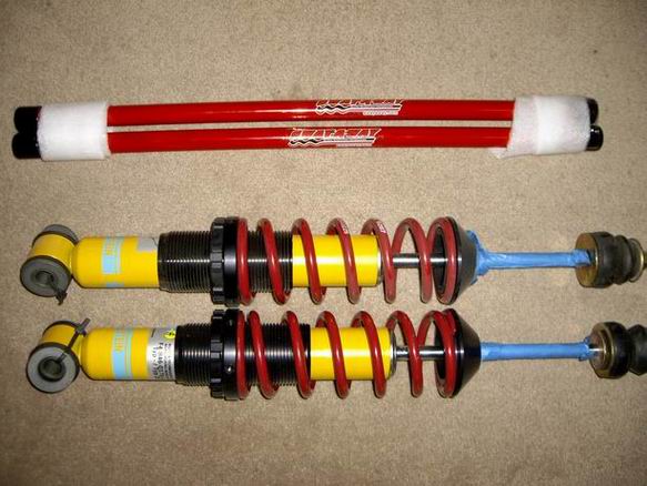
Posted by: tronporsche Oct 1 2008, 12:40 AM
Jeff, what size Or weight springs are those please ? Do only that size or weight come in red like that ? What use is those size springs for (racing, daily driving , to be comfortable, etc,) The reason I ask is I have the same set and shocks on my car that came from another car. Thank you.
Posted by: gs11x Oct 11 2008, 06:17 PM
Hi Jeff,
Can you share how you are doing your media blasting in your rust repairs? I agree with you comment about trying to grind the rust out because it removes to much metal. I want to buy some media blast equipment but I am not sure what equipment to get. Thanks
Posted by: Jeff Hail Oct 11 2008, 07:17 PM
Edited. Non auto stuff removed.
Posted by: Jeff Hail Oct 11 2008, 07:19 PM
Edited. Non auto stuff removed.
Posted by: Jeff Hail Oct 11 2008, 07:20 PM
Edited. Non auto stuff removed.
Posted by: Jeff Hail Oct 11 2008, 07:21 PM
Edited. Non auto stuff removed.
Posted by: Jeff Hail Oct 11 2008, 07:25 PM
edited. Non auto stuff removed.
Posted by: Jeff Hail Oct 11 2008, 09:10 PM
Hi Jeff,
Can you share how you are doing your media blasting in your rust repairs? I agree with you comment about trying to grind the rust out because it removes to much metal. I want to buy some media blast equipment but I am not sure what equipment to get. Thanks
I use both a professional forced pressure gun (hopper type) and a cheap hand held suction gun with a huge nozzle (Home Depot bucket is the hopper). Forced for larger areas and the hand held for smaller spot areas. I do not use sand. I use Dupont Starblast ( I think I posted somewhere way back about the Starblast). Process is straight forward. Blast until the rust is gone. Wear gloves, a windowed hood and proper respirator. I lay out a big blue poly tarp under the work area to catch the spent media and then recycle it by sifting it thru a ultra fine strainer to remove the contaminants. (pain but it works)
Since I am doing this project in stages I try to work smaller areas that can be started and completed without leaving exposed metal for periods of time.
Posted by: Wilhelm Oct 12 2008, 09:19 AM
Hi Jeff,
Can you share how you are doing your media blasting in your rust repairs? I agree with you comment about trying to grind the rust out because it removes to much metal. I want to buy some media blast equipment but I am not sure what equipment to get. Thanks
Heres my sandblasting effort............
http://www.914world.com/bbs2/index.php?showtopic=87896
Posted by: Jeff Hail Nov 30 2008, 07:10 PM
We appologize for the interuption. We will return to our regular programming in a moment.
No time to work on the tub until now. I feel like the Duracell bunny sometimes. Go,go, go......
Finished the pedal box and pedal board support. A few modifications to the original design but I am happy with the result.
Primed, seam sealed and primed again - done
Anyone who has worked/ repaired this area knows its tight confines.
Attached thumbnail(s)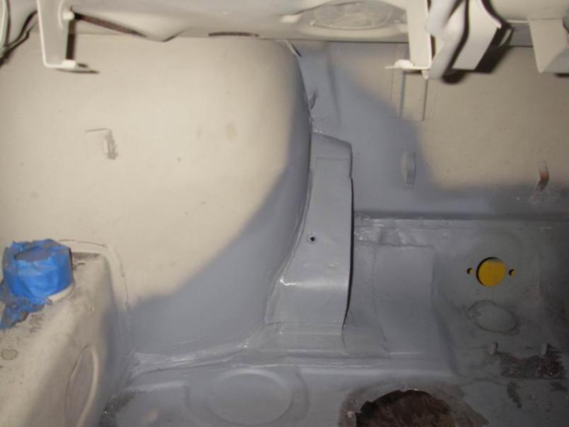
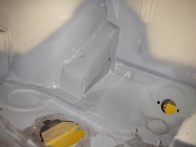
Posted by: Jeff Hail Dec 20 2008, 01:51 AM
Chris,
Really I have been working on the car. Ho Ho Ho
Attached image(s)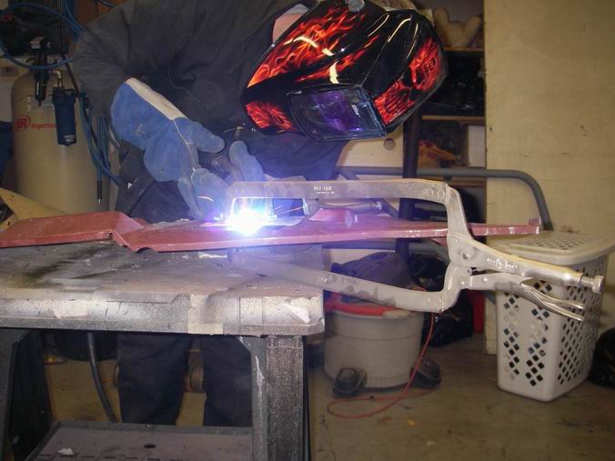
Posted by: Jeff Hail Dec 20 2008, 02:06 AM
Its been 28 degree's at night and raining/ snowing for a week. What is the best way to stay warm? Fire - of course.. Crazy thing is i'm in L.A County...snow? well a little mostly just frig'in cold.
Welded some backers/ reinforcing plates on the inside of the firewall. The thought of the PMS mount supporting a fat six with only 18 guage sheet made me think. While I'm in there add some metal. This is an area most cannot do while in there because its inaccessible. Do it once and never have to worry. No fatigue in the firewall sheet metal at a later date.
Two reasons..I can really turn up the heat when I weld the mount in and I can also tie the plates into the cage from inside the passenger compartment. Best thing is its all concealed by the inner firewall. Sano. You get the idea. Better overkill than not enough.
Attached image(s)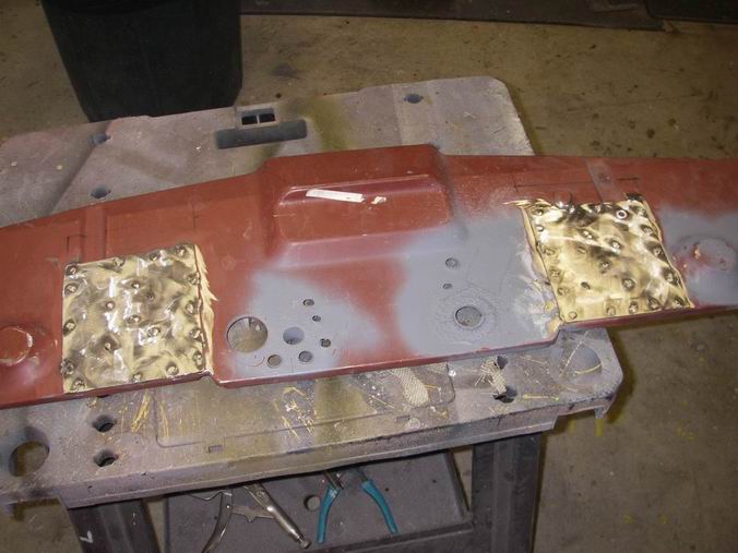
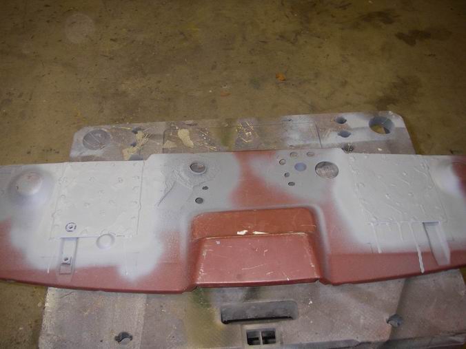
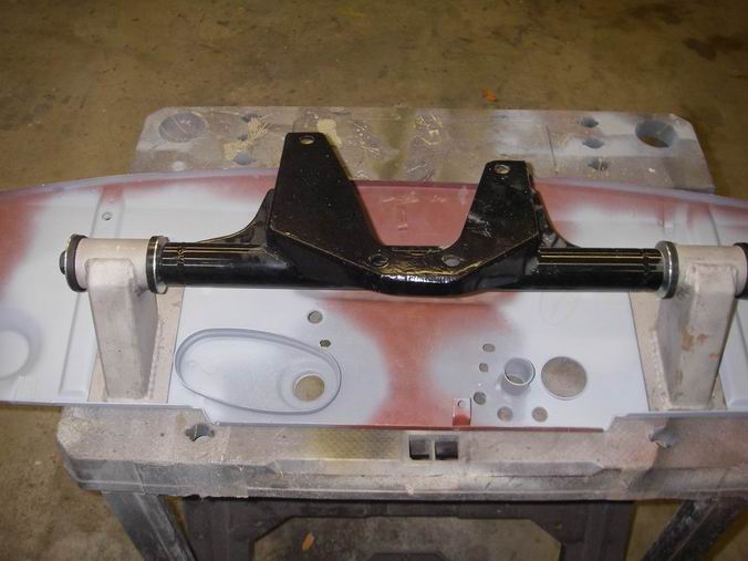
Posted by: Racer Chris Dec 20 2008, 06:22 PM
Chris,
Really I have been working on the car. Ho Ho Ho
lololol
Posted by: Jeff Hail Jan 1 2009, 02:59 AM
A few posts ago (many- somewhere on the site). I provided a glimpse on a center pull/ tunnel mounted E Brake using a 993 E brake assembly. A few reasons......get rid of the rinky dink left side E Brake and improve the system in the process. Using two right side 914 cables of equal length and relocating it to the tunnel. Full adjustment at the lever and cables from inside the car.
Here you go completed product. No modifications to the cables needed.
Yup Shea....freak of nature. Dr. FP would be proud!
Quote:Sarah Conner from the movie Terminator. "Men like you thought it up. You think you're so creative. You don't know what it's like to really create something".
Quote: Jeff Hail "Sarah be quiet- you are annoying me. Go to your room "
Happy freak'in New Year!!!!!!!!!!!!!!!!!!!!!!!!!!!!!!!!!!!![size=3]
Attached image(s)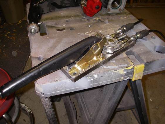
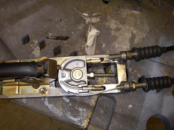
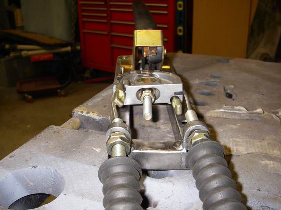
Posted by: Jeff Hail Jan 2 2009, 12:36 PM
Front floor officially done
Cut out the area that had some rust for the access cover and fabbed a square piece to insert.
Attached image(s)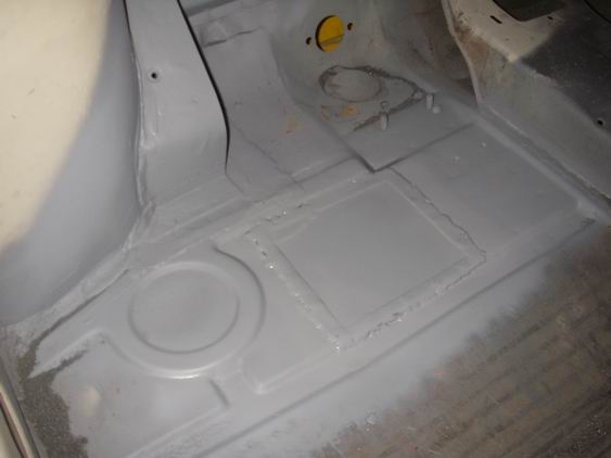
Posted by: Eric_Shea Jan 2 2009, 02:47 PM
Posted by: Jeff Hail Jan 11 2009, 07:21 PM
Final coat of epoxy primer on the front floor/ pedal box. Nice and pretty.
........and yes that is a dent in the floor just to the left of the cut in the trans tunnel.
Didnt notice it until after I primed it. It will easily be corrected with a piece of 4x4 and a floor jack. Few hits with a rubber mallet to raise the low area.
Attached image(s)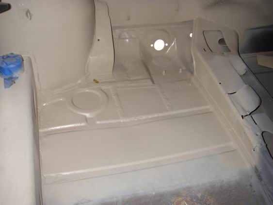
Posted by: Jeff Hail Jan 11 2009, 07:24 PM
The left side cowl is as expected. Evaluate and start cutting out the bad metal.
Attached image(s)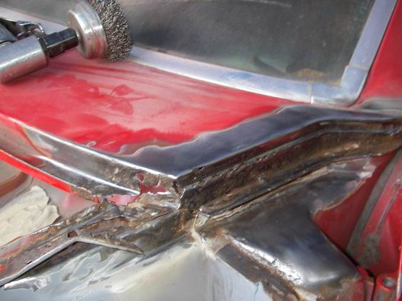
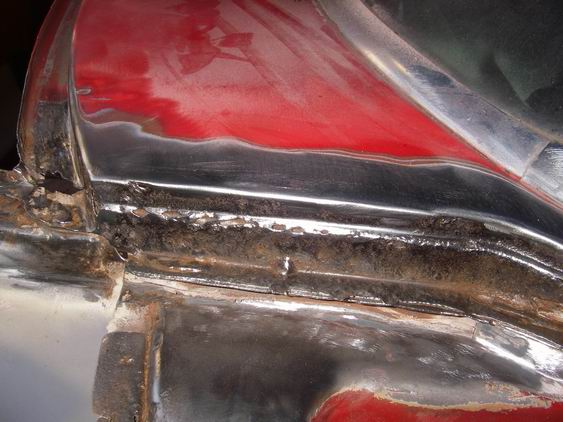
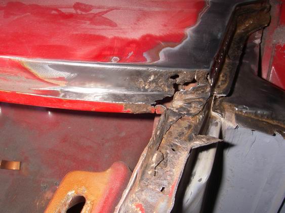
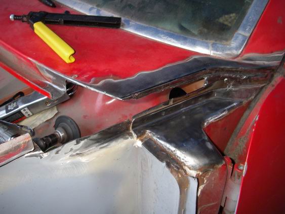
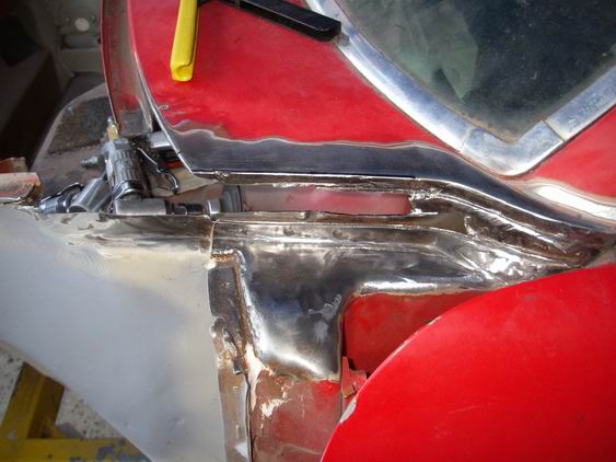
Posted by: Jeff Hail Jan 11 2009, 07:28 PM
Made a backer to go behind and underneath the cowl. Three reasons: First to set the cowl height to the hood. Second with all the heat it will minimize distortion during welding. Third I can get some heat in this area without burn through (cowl top is thin).
Getting dark. Til next time!
Attached image(s)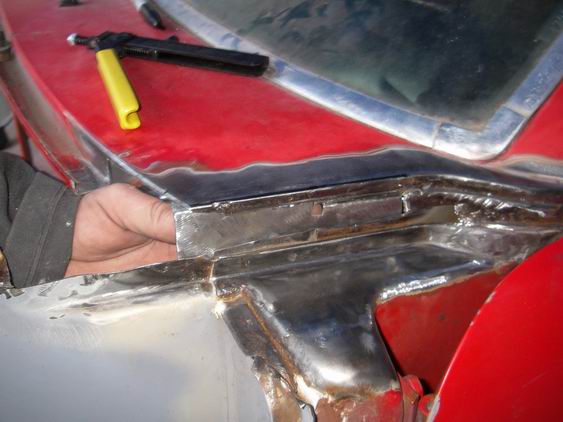
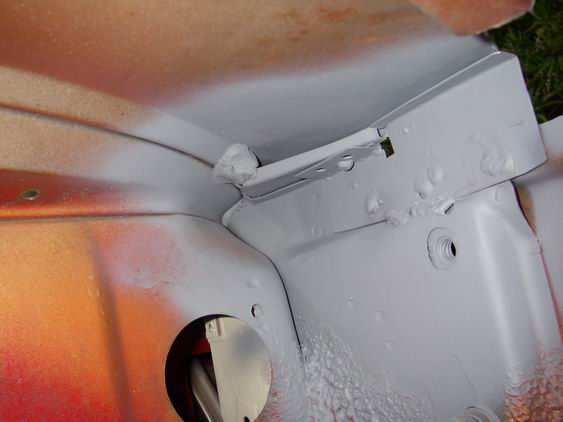
Posted by: Jeff Hail Jan 11 2009, 09:06 PM
A good friend who happens to be a full time welder asked me to design a new business card and logo for him. He's having a mid life crisis as he just turned 50 years old.
His request went something like this "it has to have fire and a skull since that's been my trademark for twenty five years. It needs to make a bold statement when I am on site and EVERYONE needs to know it's me. The rest I will leave to your imagination Jeff"
Hum? My imagination? A big burly guy who's into fire and skulls, Harleys, huge BBQ's and tat's wants to make a statement because you are having a mid-life crisis. This is you pal!
Attached image(s)
Posted by: heavydriver Jan 15 2009, 05:02 PM
If you were to replace the firewalls as well as the floor what would you do first ?
Specifically structural or ease of work considerations. Any helpful advise would be appreciated

Posted by: Jeff Hail Jan 16 2009, 09:04 PM
If you were to replace the firewalls as well as the floor what would you do first ?
Specifically structural or ease of work considerations. Any helpful advise would be appreciated
Good question. It all depends on how the car (any car) is constructed. If I was just replacing a floor pan and a lower firewall it would be fairly simple on a 914. Remove damaged/ rusted panels and then one critical issue comes up.....The floor has to be correctly aligned to the lower firewall at welding time. Even more critical if you are installing a six mount. I would tack the lower firewall to the upper firewall and let it just swing (leaving the sides and lower loose). I would then fit the floor pan/ cut to length/ tack at the forward floor seam (lap/ few plug welds to secure). Add a few plug welds to the sides for position only. Check everything for fit and then plug the lower firewall to the floor. I would then chase the perimeter with the remaining plug welds. Finally returning to the floor seam section. I would plug and fillet weld the seam overlap completely (both sides).
One hint that a few people forget when sectioning any lower panels (floor's especially), trunks etc ALWAYS postion the forward panel below the rear panel section. The reason for this is two fold. You dont want a leading edge facing forward ever. This will allow road splash/ debris to to stream past the bottom edge of the joint and not strike the joint head on. If you don't follow this rule the joint will rust/ corode due to being blasted by what ever impacts it.
Second just picture in you mind a leading edge hitting something (example:high centering a low car in a driveway or running over an object at speed). The joint can be easily torn wide open.
I recall years ago IMSA would not pass a car in tech inspection if they saw a floor that had been sectioned with the rear panel leading edge exposed underneath. In the collision repair industry its called blaphemous butchery.
On with the fun!
Attached image(s)
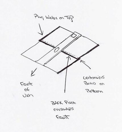
Posted by: heavydriver Jan 17 2009, 07:25 AM
Thanks for the response. Based on what I have seen being done by those with more skills I will do the following......
Put her up on a jig (I will build one like yours) and fix the hell hole first then the firewalls followed by the floor. Whew, is that a good plan or should I punt ?
Posted by: Cairo94507 Jan 17 2009, 08:34 AM
I am absolutely in awe of your skills; you are the Holy Grail of metal work. As I was reading your thread and watching the progress all I could think of was how lucky is that 914 to have this kind of skillful repair work. Love the thread; can't wait to see more.
Posted by: Jeff Hail Jan 31 2009, 07:06 PM
The tub is off the front jig. Prepped, primed and a thin coat of SKS in the crossmember tunnel and left front wheelhouse. It will get primed again later.
Attached image(s)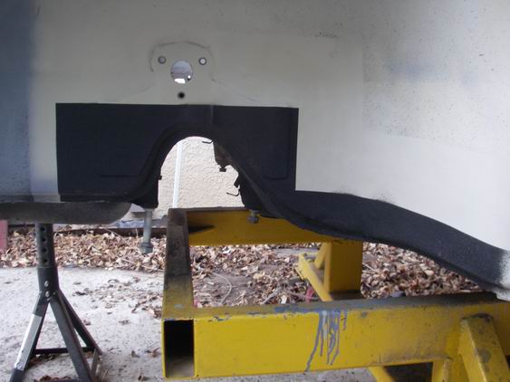
Posted by: Jeff Hail Jan 31 2009, 07:10 PM
Back to the driver side cowl. Fabbed all the little pieces. Only 2 actually.....and burned them in (the gutter and the side piece) Rough metal work done.
Attached image(s)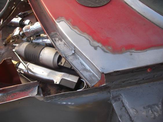
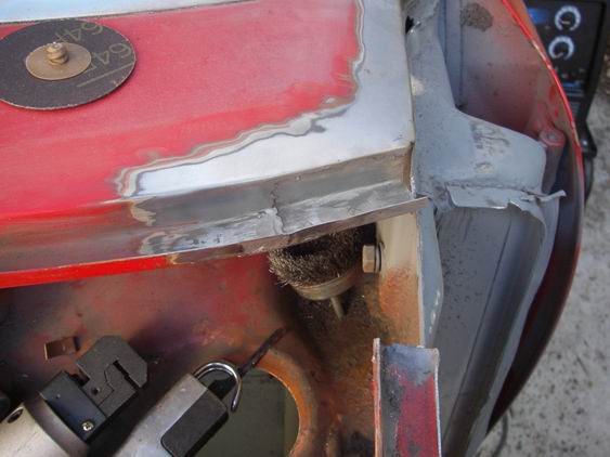
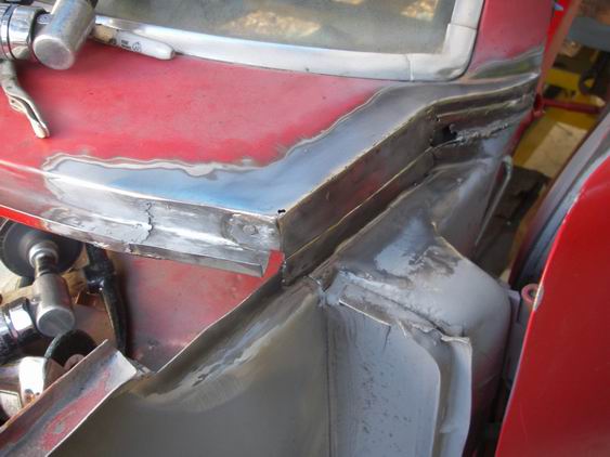
Posted by: Jeff Hail Jan 31 2009, 07:12 PM
I removed what was left of the fender gutter at the apron.
Folded down the tab on the cowl gutter to make a smooth transition and set the hieght.
Fabbed piece #3 to close the apron to the cowl gutter. More burning.
Attached image(s)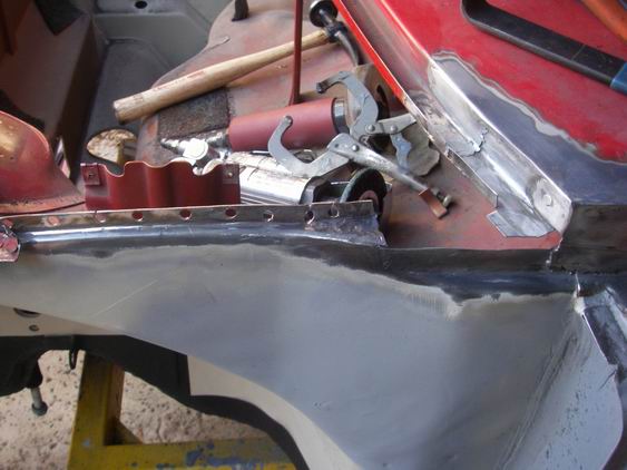
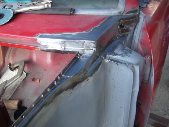
Posted by: Jeff Hail Jan 31 2009, 07:17 PM
Lots of grinding and shaping
and more grinding and shaping........
Attached image(s)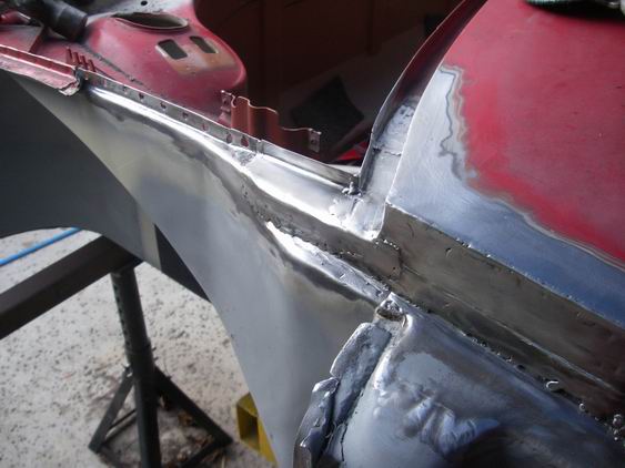
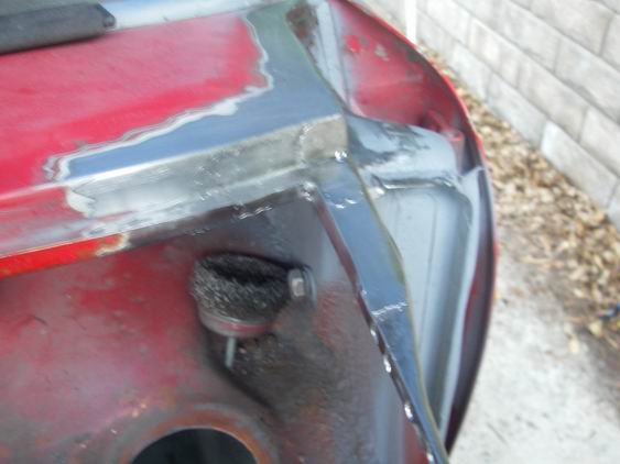
Posted by: Mike914 Feb 1 2009, 03:03 AM
Lots of grinding and shaping
and more grinding and shaping........
I did a similar repair to my '74, and word to the wise, now is the time to check the fit of the hood.
The side view looks a little bit forward on the corner of the cowl, like the corner of the hood may have a bit less gap than the center, which is exactly what happened to me...
Nice work!
Posted by: Jeff Hail Mar 21 2009, 02:09 AM
I've been quiet and for good reason.
#1: I am moving and have been packing up the home & shop which has been quite daunting. Home easy, shop not so easy. My garage is full of equipment and attic is a time capsule of rat holed Porsche and racing parts for some 23 years. I have been packing things I didn't even know I had. Some of these will go into the 914 which will be unveiled later. Surprise, surprise AND no none of it is for sale! Once I had everything out in the open I realized its a damn 401k in the making.
My escrow closes 3-26-2009 so lots to do between now and then. It's a good thing for me. Bigger, better and about the same price which in todays economic times and market is a blessing. Change is good.
#2: I am a multi-tasker (aka A.D.D ...always have more than one project going on simultaniously. I just completed a huge undertaking that started in November 2008 that exceeded all expectations. It was a rush request and I couldn't say no to it. I cannot elaborate at this time but it was worth it.
#3: New home will need to have shop organized and outfitted. So this means I will be OFFLINE for a bit. Once I am back on line the 914 becomes #1 priority from here on out.
Later for now....
Posted by: type11969 Mar 21 2009, 10:36 AM
Good luck with everything Jeff, looking forward to updates once you get back into it
Posted by: flippa Mar 21 2009, 10:42 AM
ADD is a blessing; I would be out of buisness without it. i don't understand why they surpress it with drugs!
Congrats & good Luck with the move. Looking forward to see the next installment
Posted by: Jeff Hail Jun 16 2009, 11:45 PM
Don't count me out until you see the box going into the ground!!!!!
Move completed. Dealing with house things now. Garage is secondary at the moment.
Posted by: strawman Jun 17 2009, 12:23 AM
Don't count me out until you see the box going into the ground!!!!!
Move completed. Dealing with house things now. Garage is secondary at the moment.
Good to see you haven't given up on your incredible project. I've been having withdrawals these past few months waiting for an update. Hope you can back to the project soon!
Geoff
Posted by: Jeff Hail Oct 19 2009, 01:04 AM
The house stuff is close enough. Shop has been fitted. Now its time to get back to work. Winter is coming and no time like the better to.......GET THIS BITCH DONE![size=7]
Attached image(s)
Posted by: veltror Oct 19 2009, 04:09 AM
First class, I hope to have some news on my project soon also...
Posted by: Jeff Hail Nov 13 2009, 08:19 PM
Where was I? Oh yeah....rust
I pulled the tack welded ft tube structure from under the hood to access the lower control arm bracket, floor and corner reinforcement. Wasnt as bad as anticipated. Always new it was there under the reinforcement.
Remove the corner reinforcement
Hello floor
Wire wheel the area. Floor repair will follow later as I have to make a template
and didnt have the correct guage sheetmetal.
Attached image(s)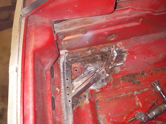
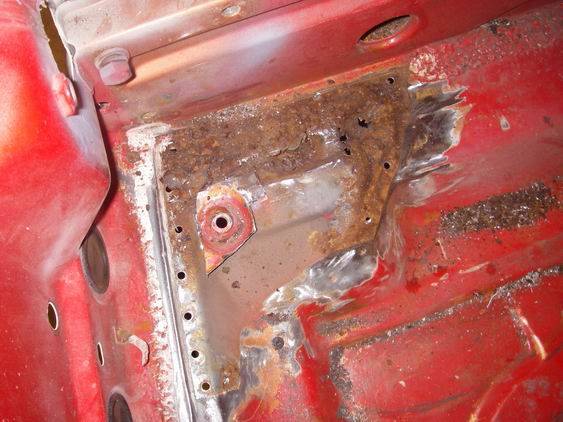
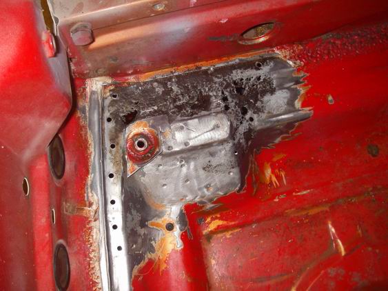
Posted by: Jeff Hail Nov 13 2009, 08:24 PM
Made a template of the reinforcement using the old one.
Salvaged the inboard portion and fabricated the new section. Lots of weird contours on this piece to duplicate. You can see the holes where the spot welds were on the old section that remains.
Presto!
Attached image(s)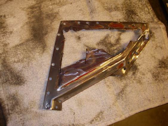
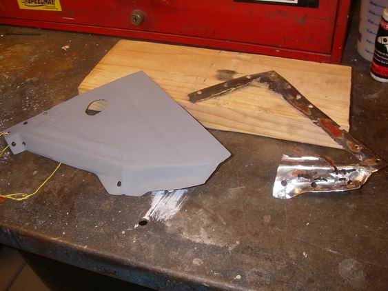
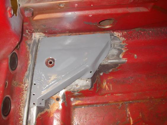
Posted by: Jeff Hail Nov 13 2009, 08:37 PM
BTW
Clayton, Clayton. Calling the Twisted one. Think were overdue for a cup of really strong Joe. Glad your back.
Posted by: my928s4 Nov 13 2009, 09:12 PM
Wire wheel the area. Floor repair will follow later as I have to make a template
and didnt have the correct guage sheetmetal.
What did you coat that rusted area with?
Posted by: Jeff Hail Nov 13 2009, 10:10 PM
Its not coated. Just Jasco metal prep. Cheap as water and works as well as anything. I just sprayed a bit on after wire wheeling the area. The rust is going to get cut out anyway under the corner reinforcement.
Posted by: brp986s Nov 13 2009, 10:21 PM
Well...Did you get a bigger garage?

Posted by: Jeff Hail Nov 15 2009, 02:11 AM
Well...Did you get a bigger garage?
Actually the shop is 2 feet shorter than the old one. But I have a hell of lot more cabinet and storage space. A 6x6x10 storage closet plus 400 square feet of floored attic storage! The shop is still in a bit of disarray but one less car equals more work space. Fire resistant dropped ceiling tiles, better lighting and sound proofing. 800 watt stereo. I cant complain and the neighbors cant hear a thing. I wanna bang all night. In space no one can hear you scream!
A 914 in process. A 1965 Harley Davidson Golf Cart (250cc Aermacchi powered 2-stroke) that will tear the balls off an EasyGo or Gator cart. The nightmare of the greens keeper.
An awesome and special woman in my life. Only the best will do.
Life is good.
Attached image(s)
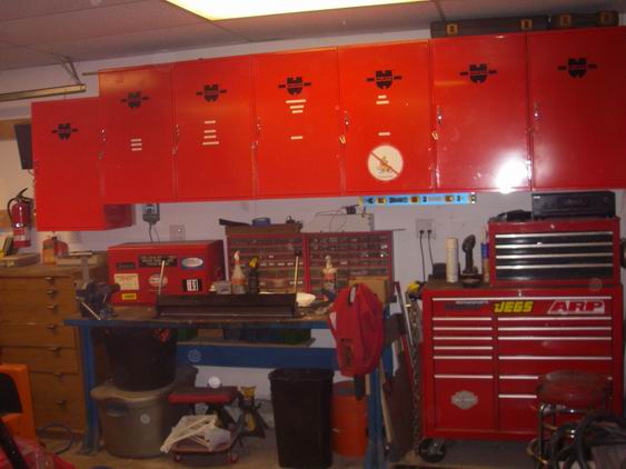
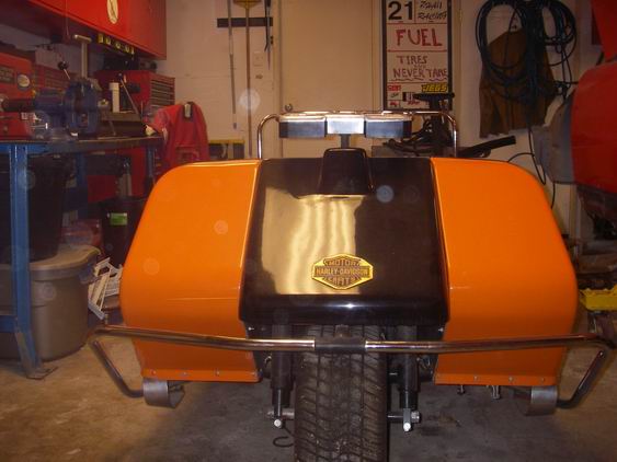
Posted by: Jeff Hail Nov 15 2009, 02:37 AM
Before I start cutting the rusted area from the front floor which really isnt bad. I had to fabricate a jig for the control arm mounting points. This is a critical area that cannot be left to guessing so when in doubt build a jig. Fifteen minutes of fab time will more than make up for improper positioning of the front lower control arm pivot bracket during repair of the affected area.
If I have to remove the bracket during repair, concerns that can be eliminated by doing this are:
Incorrect caster/ camber
Incorrect Steering Axis Inclination (SAI)
Do it once right the first time and sleep well.
Attached thumbnail(s)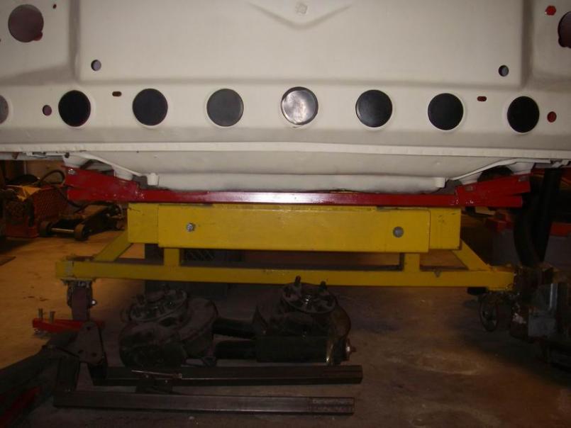
Posted by: Jeff Hail Nov 15 2009, 07:41 PM
Cut the affected sheetmetal back to good metal. Traced a template and fabricated the repair panel. In she is. Next I will install the corner reinforcement I made earlier.
Attached thumbnail(s)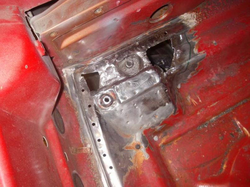
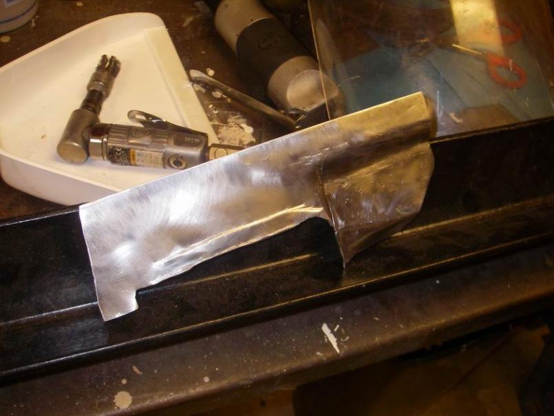
Attached image(s)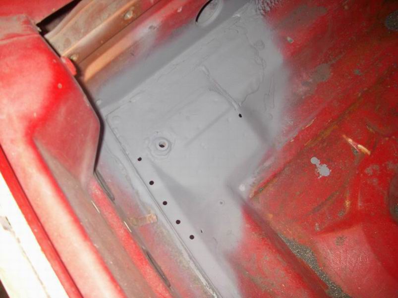
Posted by: Racer Chris Nov 15 2009, 07:46 PM
Every 914 I have worked on has its own unique rust signature.
Good work Jeff!
Posted by: FourBlades Nov 15 2009, 08:19 PM
Whoo Hoo, Jeff is back!!!
We are ready to learn from you once again.
Nice looking workshop.
John
Posted by: Jeff Hail Nov 26 2009, 02:12 AM
Ft floor done. Well almost... a ding just behind the nose panel needs some dolly work but that will take just a second.
Front tube structure fully welded in and spot primed. (A Thank you plug to Mr. Foley for the pipe work)
Attached thumbnail(s)
Posted by: Jeff Hail Nov 26 2009, 02:23 AM
Ok
I lied... I did do some work back in January. Better living through chemicals, gelcoat and carbon fiber mat. 14 inches from the inner wheel well to the outer lip of the flair. Something tells me my 9 inch Rota's are going to need some spacers.
Don't ever tell a girl her ass it fat! It will give her complex!
Attached thumbnail(s)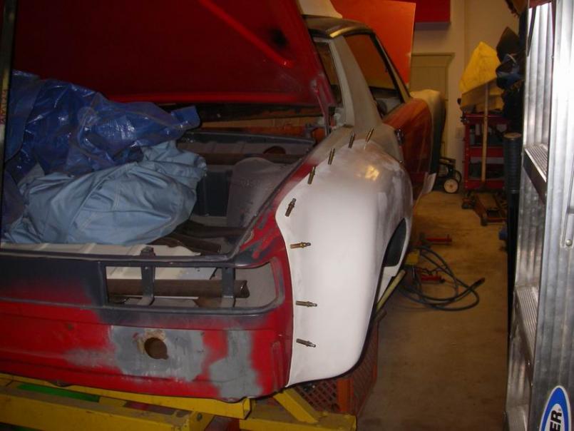
Posted by: Racer Chris Nov 26 2009, 08:49 AM
14 inches from the inner wheel well to the outer lip of the flair.
That is wide!
A stock rear is about 10" to the edge of the fender lip, measured from just above the step on the inner wheel well.
You need to put 275's in there or she'll just look flabby.
Posted by: Jeff Hail Nov 27 2009, 10:34 PM
One of last years unfinished area's. In a previous post I rebuilt the drain trough and the corner just behind the hood then life got busy.
The driver side cowl.... Done !
Ground down the rear side area and fabricated a new layer. This area is super thin from the factory where the dies stretch and thin the sheetmetal. Lots of trigger on/off to stitch it in.
Funny I forgot to reload the spool of 023 wire and had 030 in the mig. Oops but hey good penetration.
Attached thumbnail(s)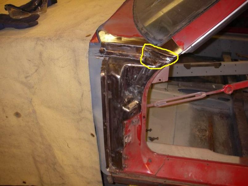
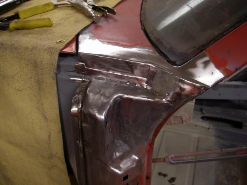
Posted by: Jeff Hail Nov 27 2009, 10:35 PM
After shaping and grinding. Came out a lot better than the passenger side.
Attached thumbnail(s)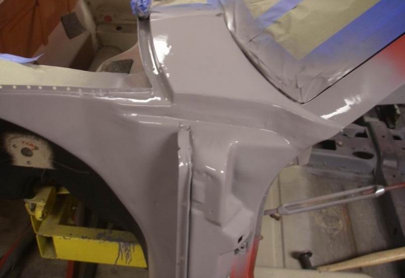
Attached image(s)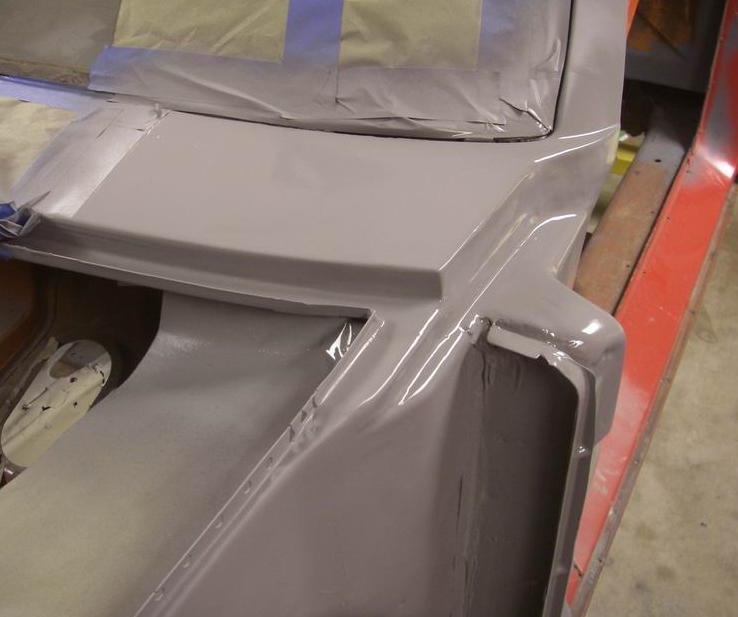
Posted by: Mike914 Nov 28 2009, 07:58 PM
After shaping and grinding. Came out a lot better than the passenger side.
How's the hood fit this area? The pics make it look a little too flat/forward at the corners to me.
Posted by: Jeff Hail Nov 29 2009, 01:10 AM
Hood fits perfect. Only the best will do.
Attached thumbnail(s)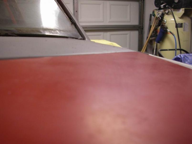
Posted by: Jeff Hail Dec 1 2009, 12:36 AM
Did ya notice the hinges? Weight Watchers for Fat Girls style.
Attached thumbnail(s)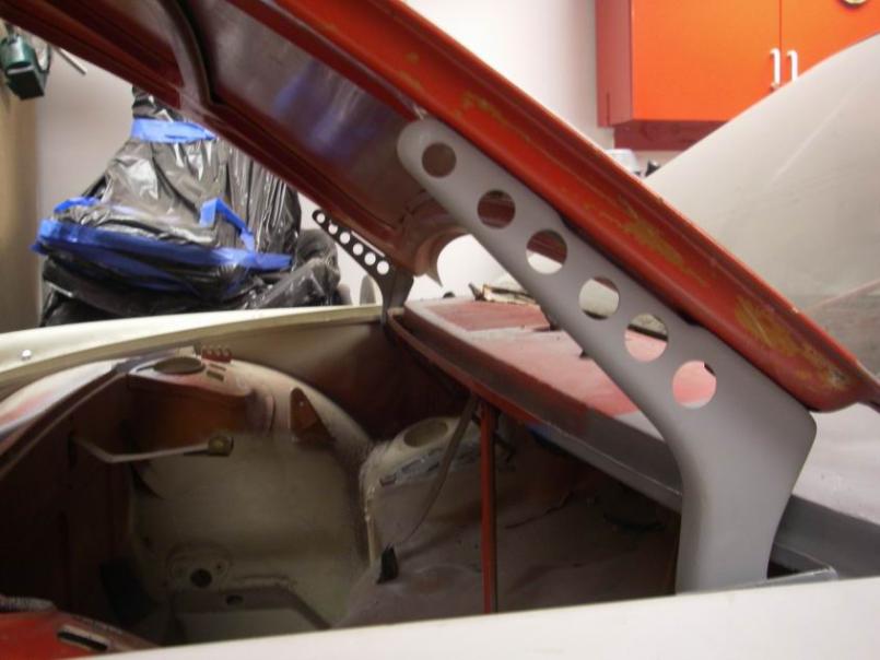
Posted by: Jeff Hail Dec 19 2009, 12:09 AM
Not planning to have any ventilation blower so no need for the cowl intake anymore. Notice the bulkhead duct (oval) holes are gone too.
Yes that is filler dust you see (holy crap he actually finally used some mud)
Attached thumbnail(s)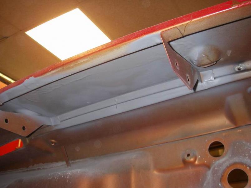
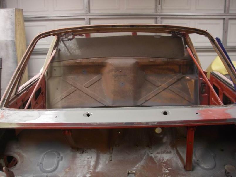
Posted by: Jeff Hail Dec 27 2009, 03:30 AM
Forward bulkhead compartment denuded of seam sealer. Stripped to bare metal looking for rust. I did find some minor surface rust scale where the two bolts secure the hood lock cylinder housing. Chemical metal prep was all that was needed. Self etching primer applied. Very clean.
Notice the brake fluid bottle bracket and hood spring brackets are removed along with the cowl vent intake.
Attached thumbnail(s)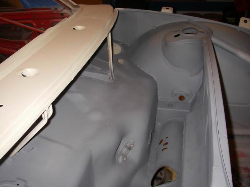
Posted by: Jeff Hail Dec 27 2009, 03:39 AM
The windshield molding clip hole's are all welded up. No need for these any longer. I will use a rubber reveal molding. Pilot holes are all welded up and epoxy primed.
Attached thumbnail(s)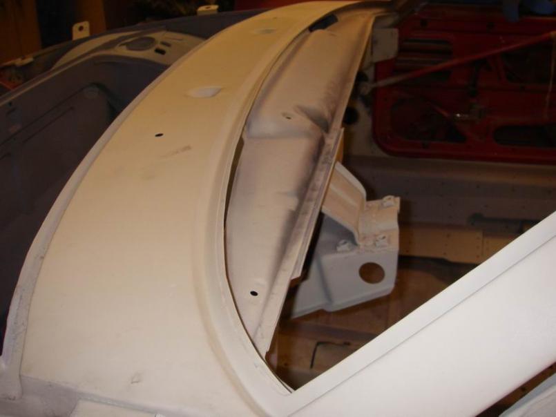
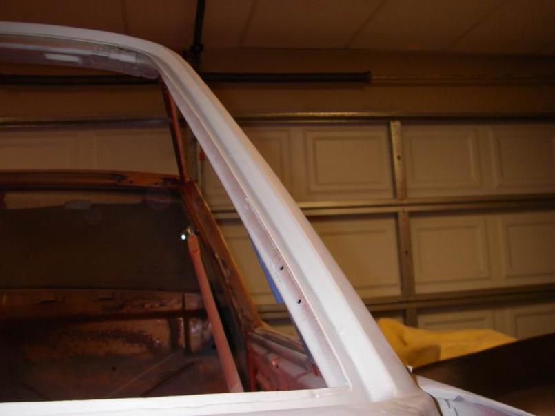
Posted by: Smitty911 Dec 27 2009, 01:14 PM
WOW, I just sat here and read your entire post.
Amazing commitment to the cause.
My '74 2.0 has the same issues as yours on the Driver and Passenger cowl area.
I was wondering what was underneith there and how to repair/replace it. Thanks for posting the pictures as you go.
Way more skills than I have, that's for sure. Looks like I need a Body Shop.
Currently no welder or skills.
Posted by: Rand Dec 27 2009, 02:14 PM
Front tube structure fully welded in and spot primed. (A Thank you plug to Mr. Foley for the pipe work)
What does this do? Sorry if a dumb question. But seriously, I don't get it. Why add weight there? And for what purpose? Seems superfluous.
Where's Aaron? He's been doing this to bike frames.
I love this thread!!! Nice work Jeff. Keep it alive.
Attached image(s)
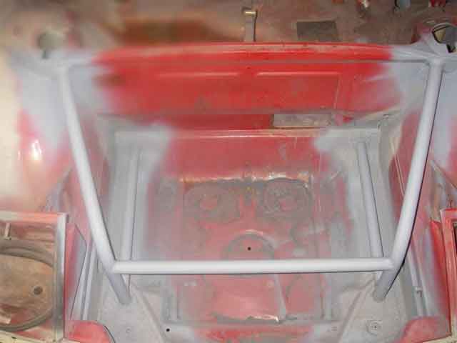
Posted by: Jeff Hail Dec 27 2009, 03:45 PM
Picture the bigger picture. Front substructure ties the towers into the lower control arm mounts and crossmember mounts, kind of faux triangulation Front substructure tied to front loop from the towers through the dash and rearward into a main loop. Central cage tied to rear longs/ towers. The 6 motor mount plates will be tied into the lower loop tubes at the lower firewall.
Ok the real reason is so I can ram shit out of the way that doesnt belong in front of me and keep driving:)
Ever notice a 914 in hard cornering? You know when the hood corner lifts up? I HATE RADICAL BODY FLEX because it defeats the purpose of suspension. Thats an easy example to picture. A properly set up car should be fun and easy to drive also providing feedback. Good suspension will only be a compromise if the chassis that supports it is the weak link.
Weight? Everything that is non essential is gone. Except one heater tube silencer which I still dont know why I put that back in? Now its an oil line guide device.
Posted by: Rand Dec 27 2009, 03:56 PM
Ok the real reason is so I can ram shit out of the way that doesnt belong in front of me and keep driving:)
I love your tude.Forgive me, I'm still clueless thinking that anything forward of the suspension is pointless. What are you bracing to up front?
Posted by: Jeff Hail Dec 27 2009, 04:41 PM
Dual purpose: Support a fuel tank and stiffen the lower control arm front pivot points. The front pivots do not take much of a side load at all but a simple floor jack test proved the floor just behind the nose panel does rise and fall with body twist.
Porsche knew this when they added a crossmember between the front pivots just behind the nose on the factory racers. Does it really do anything? It simply links the two sides together.
Posted by: Rand Dec 27 2009, 05:26 PM
Porsche knew this when they added a crossmember between the front pivots just behind the nose on the factory racers. Does it really do anything? It simply links the two sides together.
Porsche thought they knew something with the GT stiffening kits too. Turns out they made some mistakes. I guess I'm just overly anal when it comes to adding anything superfluous.
Posted by: Jeff Hail Dec 28 2009, 10:23 AM
Have to agree with you on the GT stiffening kits.
Personally I think when they cut the opening for the oil cooler the front floor was weakened between the pivots. With or without I think linking the two points does make that area more rigid keeping the control arms as parallel as can be with a minimal modification. Not eliminating flex but minimizing at best undesirable toe changes during loading.
Look at all those old original stock lower control arm bushings at the front pivot. Have you ever seen any that arent oddly deformed no matter a 914 or a 911? Normal wear for a rubber bushing with age yes but the front bushings do not take much of a load as much as just locating the control arm. Taken to the extreme of racing both 914's and 911's have been known to have contact (rubbing)between the torsion bar and inside of the control arm tube. I have seen this many times on cars that have no structural misalignment at the control points or damaged arms. The rub marks are always at the crossmember end. Torsion bar is fixed at the front of the control arm. What gives?
Posted by: brp986s Dec 28 2009, 01:12 PM
"The rub marks are always at the crossmember end. Torsion bar is fixed at the front of the control arm. What gives?"
At the crossmember end, the ID of the a-arm bushing is rotating with suspension travel, but the OD of the bushing is stationary. Consequently, over time gravity and twisting will cause the torsion bar to burrow through the bushing until it contacts the crossmember.
The further forward along the torsion bar you go there is less rotation of the torsion bar so there is less wear at the forward bushing.
But, here is something to consider. Continued loading and unloading forces around the front a-arm mount fatigues the sheet metal leading to cracks. It happened on my car and others I've seen. At its extreme the car would fall onto the tire, just like a broken torsion bar, although I've never heard of this happening. If you joined the front mounts with a hoop you could alleviate stress on the chassis. When you had the brace removed for rust repair I thought maybe you had this in mind.
Posted by: Jeff Hail Jan 24 2010, 04:17 AM
Delete
Posted by: Jeff Hail Jan 24 2010, 04:24 AM
Just before I left I have was assessing the left inner long. Removal of the motor mount and console. I figured time for more measurements before committing to more alchemy. The next step is repair of the left long in preparation of the installation of the highly awarded Racer Chris raised rear pickups.
I measured from the rear console outer hole to the front suspension crossmember rear mounting points. Triangulate both sides. I have never been a fan of the factory measurements. They provide a good detail of the body dimensions but the suspension control points have always been lacking with published data.
Attached thumbnail(s)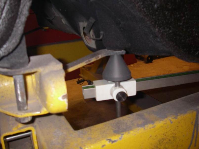
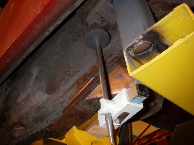
Attached image(s)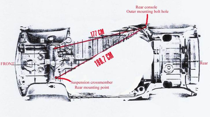
Posted by: Racer Chris Jan 24 2010, 07:04 AM
I know of a healer (nagual) in Bali who also teaches a series of invigorating movements not unlike Tai Chi, called Dragons Tears and Tapping. He goes by the name Lujan Matus and is very effective at helping people get to the inner source of their troubles, either physical or emotional. He is the living embodiment of the ancient knowledge written about by Carlos Castaneda.
BTW, the reason the torsion bars rub the inside of the control arm is because the bar is supported by the torsion bar adjuster which acts s a lever since its point of contact is 2 inches away from torsion bar centerline. This lifts the rear end of the bar as the vehicle weight is transferred through the a-arm.
Posted by: Racer Chris Jan 24 2010, 07:15 AM
At the crossmember end, the ID of the a-arm bushing is rotating with suspension travel, but the OD of the bushing is stationary. Consequently, over time gravity and twisting will cause the torsion bar to burrow through the bushing until it contacts the crossmember.
The torsion bar is nowhere near the bushing, which is outside the control arm tube.
Both bushings are affected equally by the a-arm rotating as the suspension moves up and down. They have no contact with the torsion bar but they do lose plasticity as the rubber ages. As the rubber hardens over time it may transmit greater forces into the carriers instead of absorbing them.
It is the aging rubber which causes the forces to be transmitted into the sheet metal. There is hardly any force around the front mount from the torsion bar. If the sheet metal actually breaks it will not cause the suspension to drop like a broken torsion bar since the lifting forces aren't transmitted through the front mount.
The only thing I have ever seen in that area is the mounting reinforcement broken free, due to inadequate spot welds from the factory.
Posted by: Thomas J Bliznik Jan 24 2010, 10:13 AM
I am on leave. Family issues, woman is upset with me. A spur of the moment short break from the daily grind. What else is new? Currently I am in Nusa Dua. I lost a day somewhere in flight between here and Taipei , strange it is. Ten different languages spoken all around me. Monkeys screaming all night outside my villa window. My cell phone says its California time 1-24-10 2:11 am but it’s really 6:15pm here. Time is an illusion right now. Real strong East Java coffee at the Moka Cafe will cure this I hope? This is so cool. Forget getting outside the box. The box doesn’t exist here. I could live here. My guest (Nurse Carol) is so appreciative to be my travel companion. Asked her to go to Bali with me on a moment’s notice due to other upset woman being stubborn and hard headed. (The Twisted One -Clayton would understand)
Someone do something about those monkeys.
Wow, Jeff your metal workmanship is off the chart.
Your personal life is too. Advise: Shoot the monkey's with your handgun and send a photo of (Nurse Carol).

You are an inspiration to all 914er's.
Tom
Posted by: brp986s Jan 24 2010, 11:32 AM
[quote] Continued loading and unloading forces around the front a-arm mount fatigues the sheet metal leading to cracks. [/quote]
It is the aging rubber which causes the forces to be transmitted into the sheet metal. There is hardly any force around the front mount from the torsion bar. If the sheet metal actually breaks it will not cause the suspension to drop like a broken torsion bar since the lifting forces aren't transmitted through the front mount.
The only thing I have ever seen in that area is the mounting reinforcement broken free, due to inadequate spot welds from the factory.
[/quote]
Not true. And the bushing is irrelevant. If 500 ft-lbs of clockwise torque is required at th rear of the t-bar to suspend the car, there better be 500 ft-lbs counterclockwise torque at the front, or that sucker is gonna fall. The chassis sees 100% of that torque. Dynamically, the forces can vary considerably depending on spring rate and etc, and those forces do in fact fact fatigue the chassis - I've seen it.
Posted by: Racer Chris Jan 24 2010, 04:13 PM
The chassis sees 100% of that torque.
Yup, almost all of it through the rear support crossbar - at the adjuster. Nearly 0% is applied through the front mounts, except for the resistance of the bushings!
If your car is any different you have something else wrong.
The end of the t-bar connected to the a-arm is at the front. The end of the t-bar connected to the chassis is at the rear. QED
Posted by: Jeff Hail Jan 30 2010, 12:55 AM
I forgot to post these before I went out of town. Boredom today and itching to burn some metal when I get back. I hate leaving in the middle.
Left inner long: Typical rust at the bottom of the rail from the motor mount forward.
Exploratory cutting until I hit good steel. Fabricate the lower portion of the long, flange it and burn it in. It was easier to shape the rear upward angle after the front lower portion was tacked in. 16 guage tends to want to hold its memory.
Still not done here but had to leave in the middle. Lots of finish work and weld grinding to do. Need to add a piece at the rear of the motor mount recess area but will hold off until I see what Foleys raised pickup kit extends to.
As a side note: The motor mounts, heater tube and silencer, ebrake handle mount will not be reused.
Attached image(s)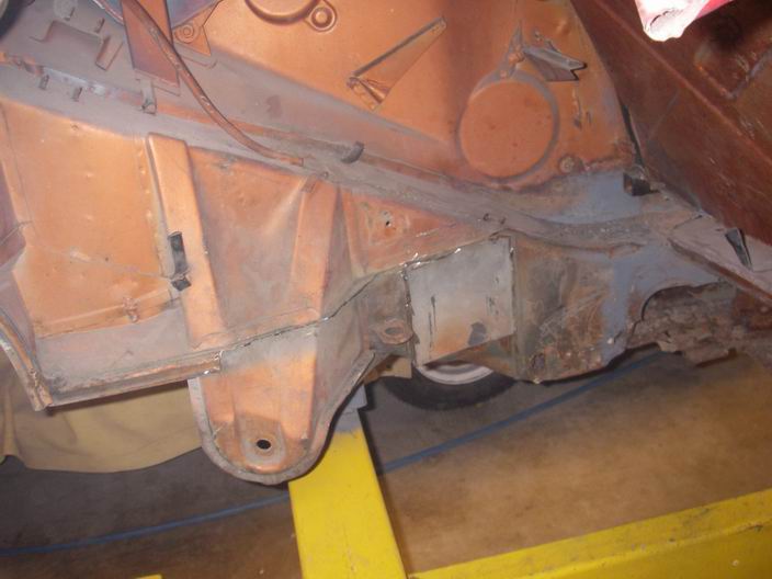
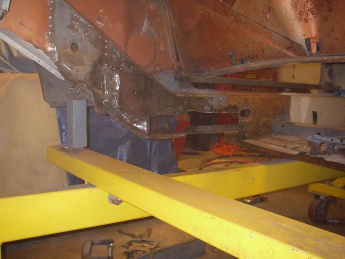
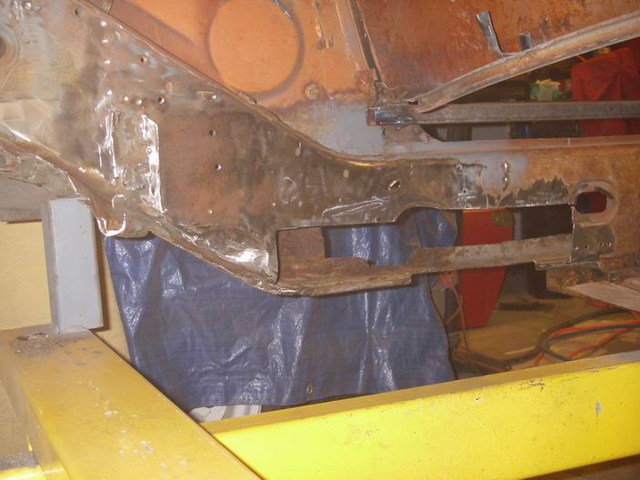
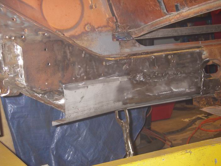
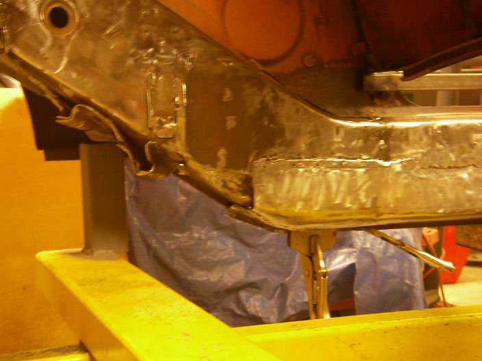
Posted by: Jeff Hail Feb 3 2010, 12:26 AM
mis·cel·la·neous rambings
I'm back. Interesting leave of absence. Women can be strange at times. Never can understand them can we?
Back to work. Anyone ever notice my photos are semi myopic? Cant ever show too much can you?
Here is where I am at:
Front body is 98% done. Front bumper and fenders just need to be hung. Dzus fastener mounts are all located. Just need to complete the finish work on the left fender and basicly done.
I havent come to a conclusion on headlamps yet but I hate the pop up lids - so they must go. Considering the CA laws on lamps some ideas have come to mind. Just like a formula in racing its all really open to interpretation and the risk.
Attached thumbnail(s)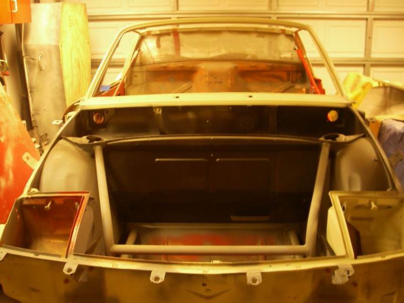
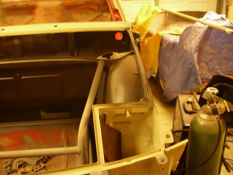
Posted by: Jeff Hail Feb 3 2010, 12:30 AM
Working on the left inner long. Its done. Just need to replace the outer long and good to go. Threw the Engman stiffener on there for looks.
I am getting ready for the rear floor section and lower firewall installation. I'm excited.
Attached thumbnail(s)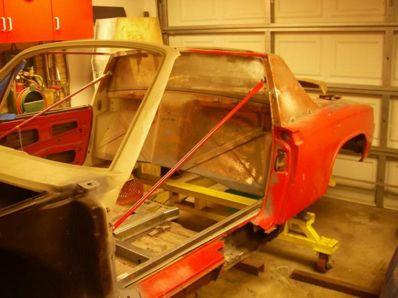
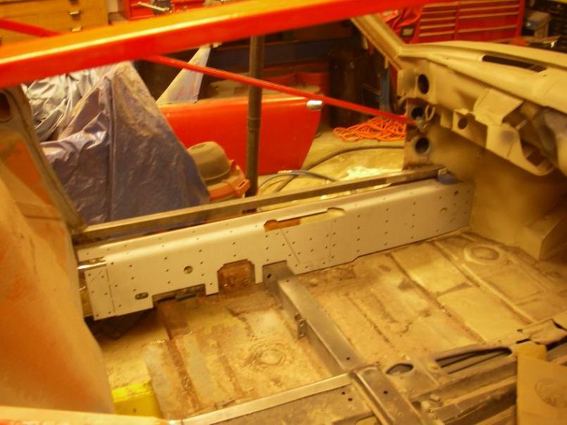
Posted by: Jeff Hail Feb 3 2010, 12:34 AM
Completed the tunnel repair patch for both sides. This will be plug welded once I install the floor. Fitment prior to floor cut and trim.
An afterthought! Porsche/VW should have made the tunnel the same height as the longs. Would have made a much stiffer platform. Shorten the shifter a bit and well.. it didnt happen.
Attached thumbnail(s)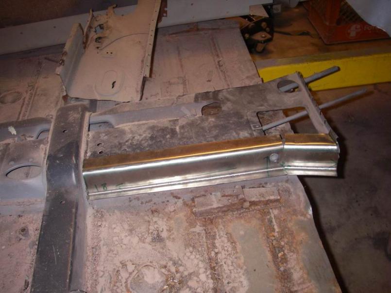
Posted by: strawman Feb 3 2010, 01:29 PM
Hi Jeff,
Lookin' great!
I can't wait to see what you come up with for the headlights. I have mocked up my radiator mounting for my Suby swap, and the upper mount bar and airflow would be much better IMHO without the headlight boxes to deal with.
I've got a front fender cut that I hope to use to mock up HID bulbs inside the factory turn signal pods... much easier on the workbench than on the car.
Geoff
Posted by: bcaschera Feb 3 2010, 05:38 PM
The turn signal pods are just begging to be stuffed with some nice HID lamps. I found some high/low HID's from PIAA and i believe they would fit nicely. The only problem being the cover and the price  . This project looks great by the way... I wish i had half the tools and 1/8 the skills you have. Keep it up
Posted by: Jeff Hail Feb 3 2010, 06:24 PM
The recent copy of Exellence provided a few extreme ideas.
Posted by: Jeff Hail Feb 15 2010, 10:46 PM
The Redhead has me stirred up!!!
Need to take it out on some 16 gauge steel.
Ok,
Fabricate the closing plate at the rear of the left outer long (rocker to us body guys)
Start with a big flat piece of 16 gauge steel. A little bending in the brake. Some trimming and there you go.
Attached image(s)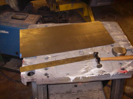
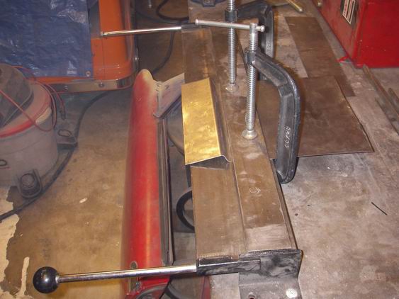
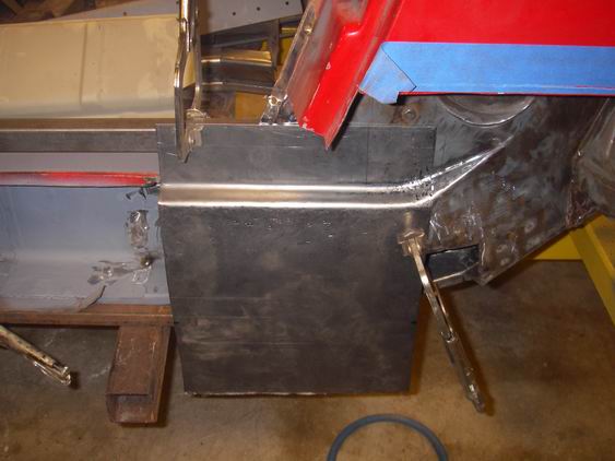
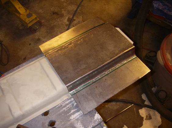
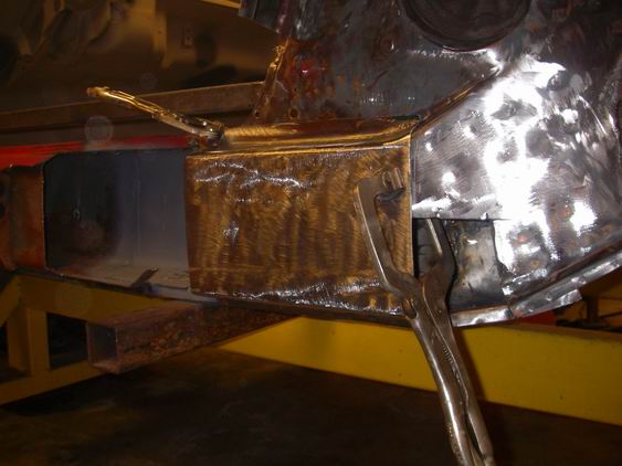
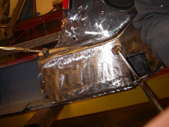
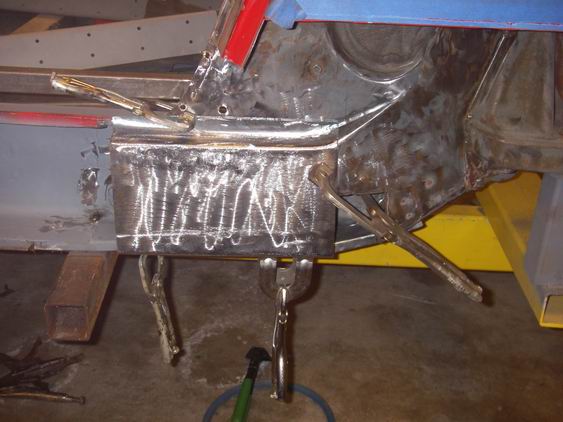
Posted by: Jeff Hail Feb 21 2010, 10:45 PM
The Red Head has me really stirred up! And she probably still has the link I sent her 8 months ago. I do care about her.
Left inner long has been repaired. Last will see of it. Should have signed my initials on the inside before I closed it up.
Next: Prepare the new outer long. Fit and add a sleeve for the infamous Hail butt weld. Sleeves make the joint twice as strong and provide a solid joint to burn in without blowing holes. A tight fitting backer is the key to a good structural joint. Really not a butt weld but a modified butt/ lap... kind of.
Attached thumbnail(s)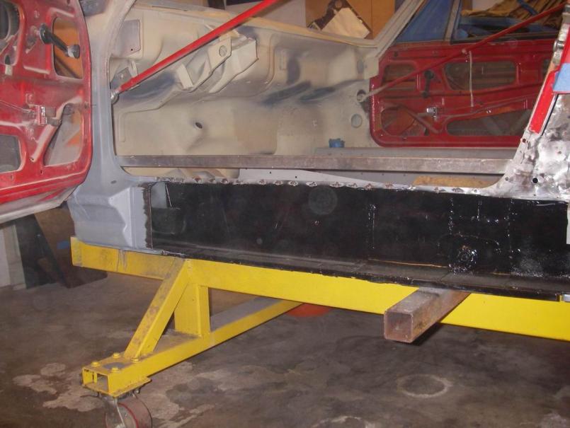
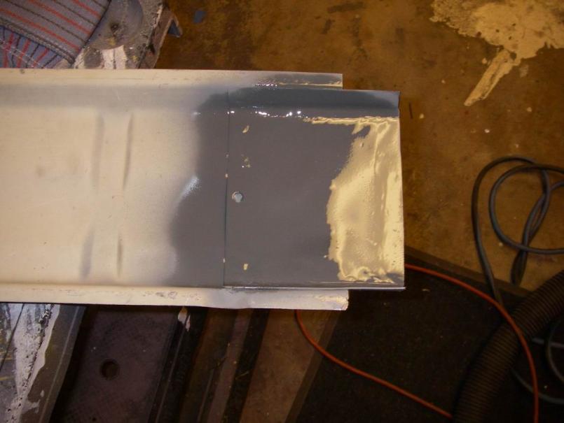
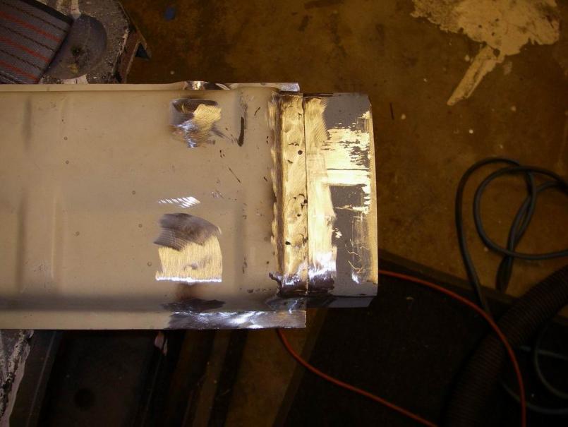
Posted by: Jeff Hail Feb 21 2010, 10:48 PM
Test fit of the Left Outer Long. Check for level and top and bottom flanges.
Clamp in place.
Punch the requisite holes and grind the flanges as appropriate.
Attached thumbnail(s)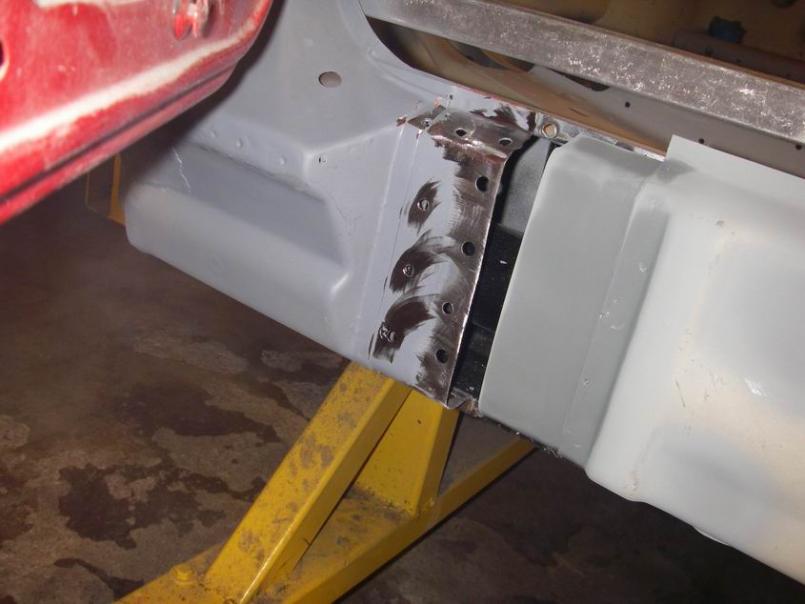
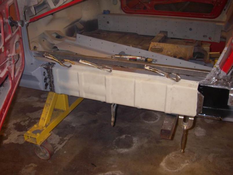
Posted by: Jeff Hail Feb 21 2010, 10:49 PM
Lets burn some metal. Alchemy!!
Grinding the plugs is next. BTW.. the upper flange was welded on the inside as I pre-drilled the holes on the inner long. Makes for a better cleaner finished product on the outside.
Attached thumbnail(s)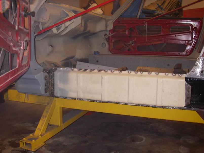
Posted by: Jeff Hail Feb 21 2010, 11:09 PM
I removed the brace just above the inner long before I welded the outer together.
The door gap stayed perfect.
Lot of talk lately on the site about twisted chassis when welding in roll cages and long reinforcements.
The only conclusion is "Occums Razor".. aka welding to fast. I burned the outer long in about 45 minutes while piping in air flow with an air nozzle laying inside the long. Just a bleed of air flow to cool the metal as I plugged along.
I would say I generated the same amount of heat welding the outer long as installing an Engman reinforcement. Weld slowly! Take your time.
Attached thumbnail(s)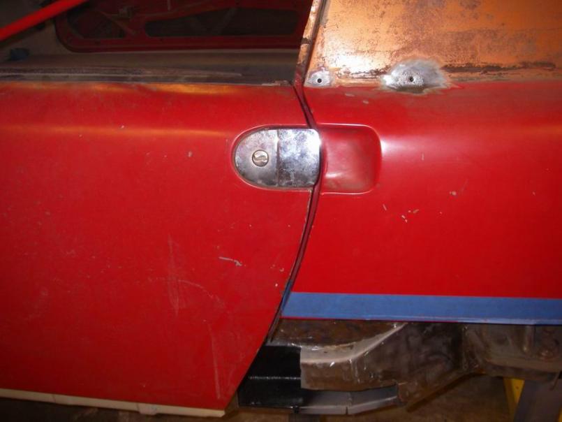
Posted by: Eric_Shea Feb 27 2010, 03:38 PM
Jeff, What method did you use to get the support bar out of the hinge?
(nevermind...upon further inspection, it looks to still be in place.)
Posted by: Jeff Hail Feb 28 2010, 02:56 AM
Hi Eric
Posted by: Jeff Hail Feb 28 2010, 02:58 AM
A few mnutes to play...
Final fitting of the rear outer rocker closing plate. Burn it in! I will grind all the welds down tomorrow.
Attached thumbnail(s)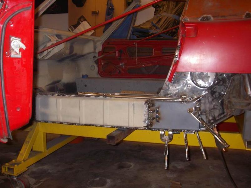
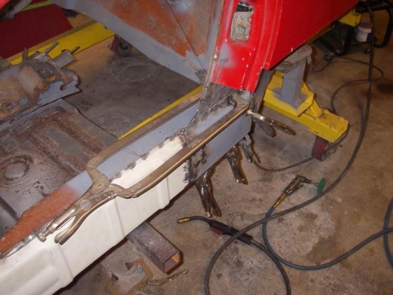
Posted by: Jeff Hail Feb 28 2010, 03:06 AM
Ok shit that hurts. Anyone who works with sheetmetal is gonna get a "hurts donut" inevitably. Got this one when the vise grip slipped and banged my knuckle on the edge where the qtr panel is cut off for access. Yep it went to the bone and was a bleeder. Probably should have gotten 3-4 stitches. No time but cyanoacrylate closed it right up.
Attached thumbnail(s)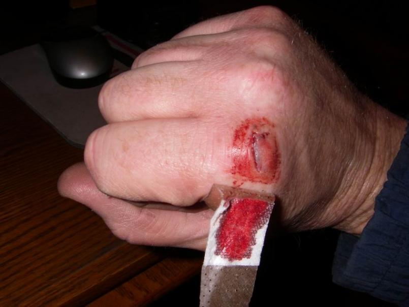
Posted by: rick 918-S Feb 28 2010, 08:05 AM
Nice work Jeff! REAlly nice gash!
Posted by: Krank Feb 28 2010, 09:07 AM
A little lemon and salt on there and I bet the vodka would go down really fast! Nice thread Jeff, lots of great info for peeps of all levels here. Thanks for all the extra time spent on pics and documentation. It takes enough time just getting the work done.
Posted by: Cairo94507 Feb 28 2010, 09:25 AM
Wow; Jeff you are one talented man. Any chance you might move to Alamo California anytime soon? I would love to have your skill set.
Posted by: d914 Feb 28 2010, 10:40 AM
I WAS married to a red head!! Say no more I fully understand!!!!!
Posted by: Eric_Shea Feb 28 2010, 11:14 AM
One way to get some "gash"
Posted by: Jeff Hail Mar 1 2010, 11:55 PM
One way to get some "gash"
It was the Nurse's recommendation to apply (cyanoacrylate) to my wound. Reminded me about the movie :What About Mary... "its a bleeder"! Ha!
I said what? She responded "its just Crazy Glue". I said I know but... she said "shut up and do it or your going to the ER"... ER holy crap? Not me...its just a flesh wound. The Nurse said its not a just a flesh wound... its serious because its been bleeding for seven minutes. I responded soooooooo. She said "you're such a typical male".. I responded with yep!
I laughed. I actually know how to install sutures...Ive done it in an emergency situation. Butterfly sutures to be exact. The ER Surgeon was impressed with my sewing capabilities. "He said he would have lost the leg". I responded "Singer would be proud".
Ok! Crazy Glue it is. Made my eyes water. The glue not the Nurse! It's hot... The Nurse not the glue.
The Red Head is still upset with me! Why me?
Posted by: Jeff Hail Mar 2 2010, 12:06 AM
Grinding of the welds done.
Well maybe not! Ok almost. My knuckle hurts like a mother... " ....
Close enough. I little touchup with the Mig and its done. (unprimed area)
I'm going to bed! Between the Redhead and the Nurse I've just had enough...I'm done for now!
Attached thumbnail(s)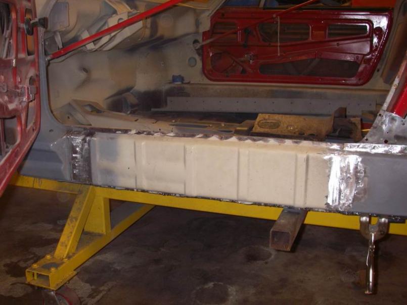
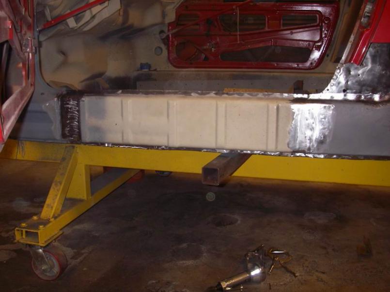
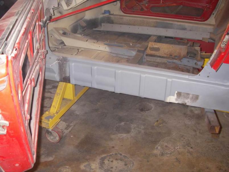
Posted by: Jon Fernandes Mar 2 2010, 10:03 AM
Looking great! Very clean repair. Keep it up!
Posted by: Gigamight Mar 2 2010, 10:38 AM
I just found this thread, been looking through and learning quite a bit. Thanks for all the pics, they're helping a newbie learn some tricks.
BTW... Redheads are crazy.......I mean SCARY crazy................I mean kill-you-in-your-sleep CRAZY!!! I'm just sayin. It's the freckles that pull us in.
Posted by: Zardozz Mar 2 2010, 12:53 PM
My boss is a redhead. Ya just gotta say yes and nice shoes a lot
Posted by: kwales Mar 2 2010, 01:32 PM
Redheads never forget.
I know, been married to one for quite a while.
Posted by: Jeff Hail Mar 2 2010, 03:20 PM
Oh and very familiar with them. I see the humor clearly. Afterall I am also a red head. I won't kill anyone in my sleep though.
Posted by: Archie Apr 6 2010, 11:45 AM
I see you have the same MIG welder as I do. Do you ever feel the need for a TIG? I certainly could use one.
Wow :o
:wttc:
This'll be a fun one to watch.
And Eric I will be calling you.
Floor contd.
Damn cool welding helmet if you ask me!
Posted by: Root_Werks Apr 6 2010, 01:21 PM
Posted by: Jeff Hail Apr 6 2010, 05:01 PM
I see you have the same MIG welder as I do. Do you ever feel the need for a TIG? I certainly could use one.
Wow
This'll be a fun one to watch.
And Eric I will be calling you.
Floor contd.
Damn cool welding helmet if you ask me!
I love my Miller 180. It performs very well. No complaints.
I always have a need to TIG. I let my friend handle the TIG for me. He is better than I and his welds look like liquid art. For the cost of a six pack it doesnt pay for me to purcahse a TIG unit.
Funny part is we did a test. I welded 35 gauage sheet steel with a MIG by using a really long ground cable. My welds came out better than his. The TIG could not be turned down enough and the bead was to proud. Everything has limitations.
We then turned to sheet aluminum. I gas welded mine and we did a distruction test which passed. The bead looked more like a blend with gas.
The TIG was a work of art on thin aluminum sheet. Nothing compares.
I always have a need to TIG.
BTW: I started a bathroom remodel so I stepped back from the 14 for a bit.
Posted by: Jeff Hail Apr 6 2010, 05:03 PM
Oh PS... The Red Head is back!
Posted by: Jeff Hail Jun 22 2010, 06:11 PM
Still here. Got sacked with some family issues and a bathroom remodel.
The Redhead is gone permanently and for whats its worth... its so peaceful without her drama.
Posted by: Jeff Hail Jun 22 2010, 06:31 PM
BTW: If anyone is interested I have this for sale in the Ad's
http://www.914world.com/bbs2/index.php?showtopic=108345
Posted by: Silverstreak Jun 22 2010, 08:34 PM
You had me worried there for a sec. I thought maybe you had to sell the project.
Posted by: Jeff Hail Aug 18 2010, 07:46 PM
I never get rid of anything it seems.
Been busy... not as much as I'd like but busy.
Trouble I have now is all the stuff from the house remodelling in the garage.
Whats my tag line?
Attached image(s)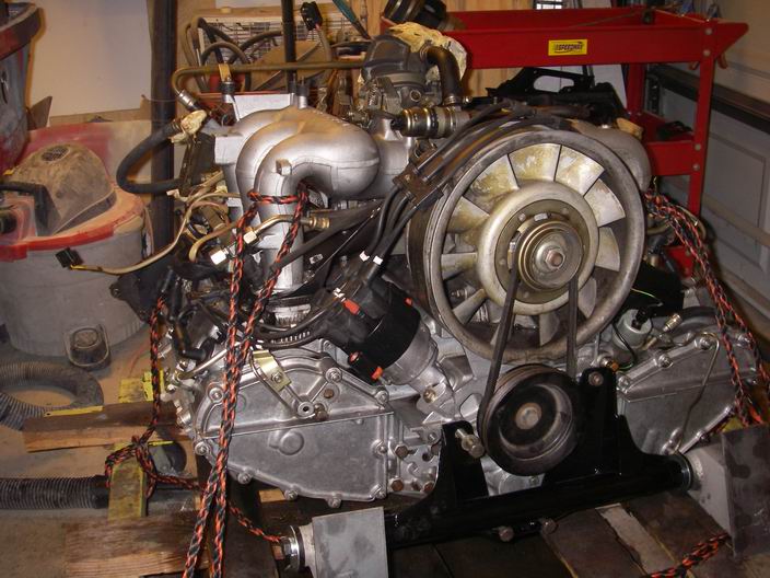
Posted by: Jeff Hail Aug 18 2010, 07:58 PM
Shiny things are good.
Attached image(s)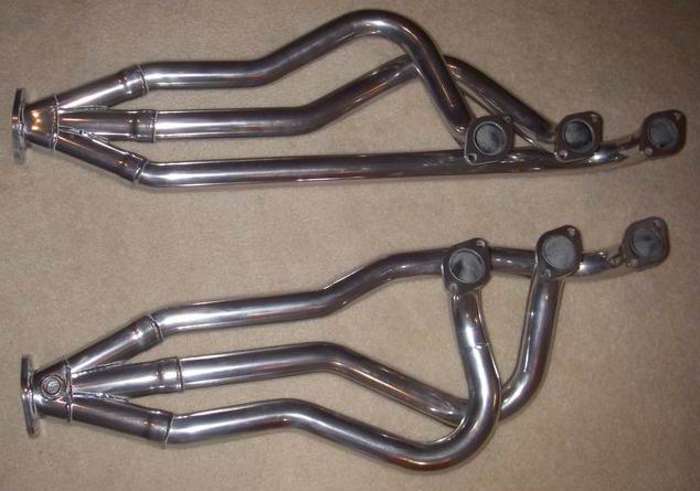
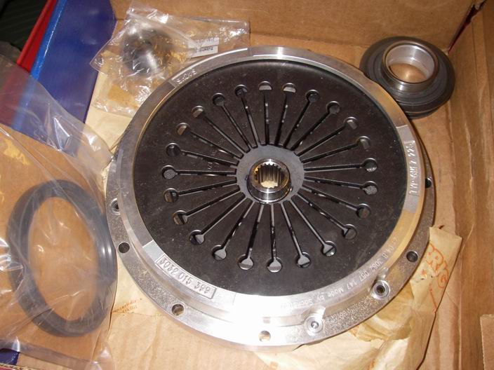
Posted by: Jeff Hail Aug 23 2010, 08:56 PM
A little time out for play.
Stopped by my friend Chris' house for an overdue visit. Hey and it only has just shy of 4700 miles on it.
Attached image(s)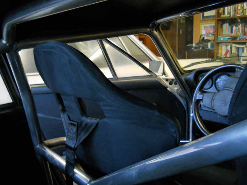
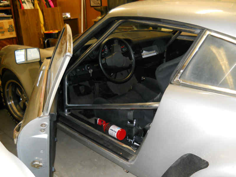
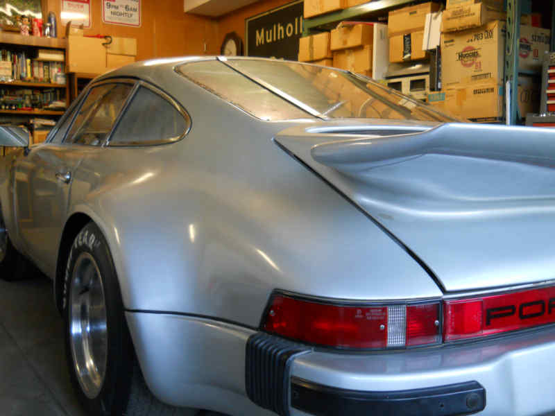
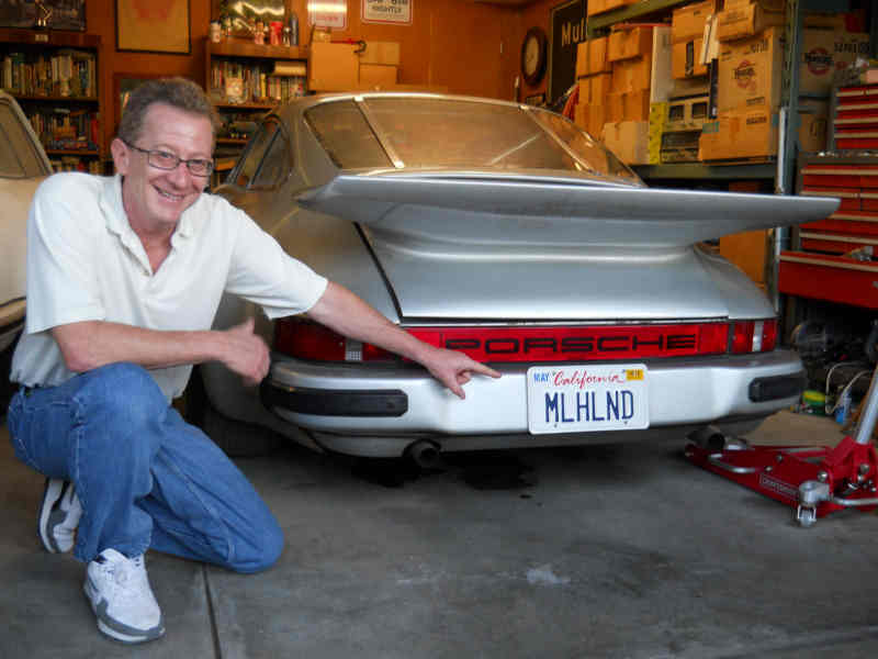
Posted by: Eric_Shea Aug 24 2010, 08:40 AM
Legend...
Posted by: jmill Aug 28 2010, 06:58 PM
How the hell did I miss this one? Fantastic work.
Posted by: Jeff Hail Sep 10 2010, 10:07 AM
Filling up yesterday. Very cool pump display. 911 Turbo!
Attached thumbnail(s)
Posted by: pcar916 Sep 10 2010, 10:11 AM
... especially the part about filling up the gas tank in the rear of the 911! Like that's gonna happen.
Posted by: Jeff Hail Sep 24 2010, 12:41 AM
Things that spin!!
Most people don't think about this or even know about it. 1st and 2nd order vibrations. When things that spin go round and round they generate vibrations. Crankshafts, cams..etc. What you don't want in something that spins is an orbit or spinning off center due to imbalance by whatever cause. This creates a whole mess that I understand mentally but would rather not deal with. So I leave this to the professionals.. The guys who balance stuff that spins.
This is where the drag racing guys come into play. As they say if it spins balance it! We all understand that balancing is not just cool but critical.
Flywheel machined and brand spanking new Sachs Aluminum Power Clutch. Lets see how good the Sachs quality control is from a dynamic standpoint? Surprisingly it was lackluster.
Enter Dave Kemblowski aka "The Balance Shop"
Flywheel, ring gear and pressure plate balanced as a rotating assembly. I was surprised at how much material was removed to properly balance the new Sachs pressure plate. For the whopping sum of $45 Dave balanced the entire indexed assembly to exceed Porsche specification which normally is just the flywheel.
Check out the bore's that were drilled. Thats a lot of material. Small price to pay. Some may recall that Porsche had an issue with flywheel bolts loosening. This was rectified later with revisions and adding 3 more bolts to the flywheel. Like I said small price to pay.
Attached thumbnail(s)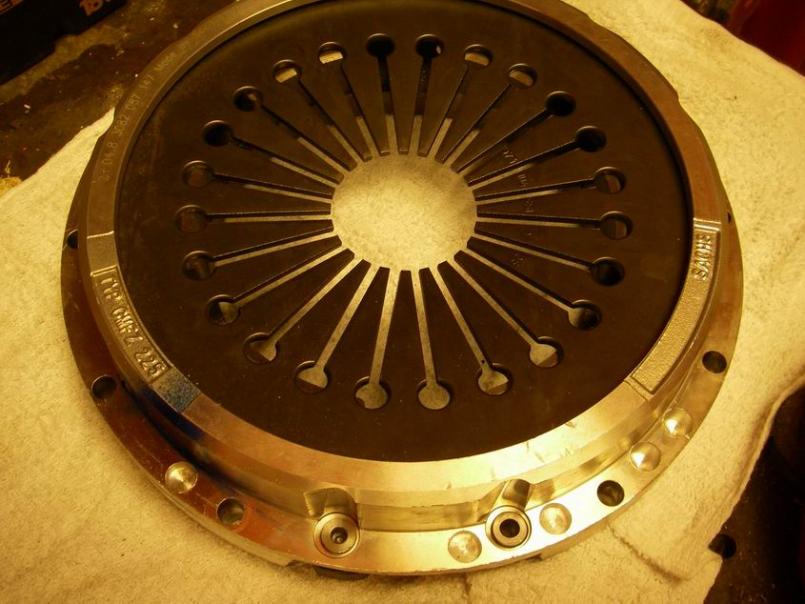
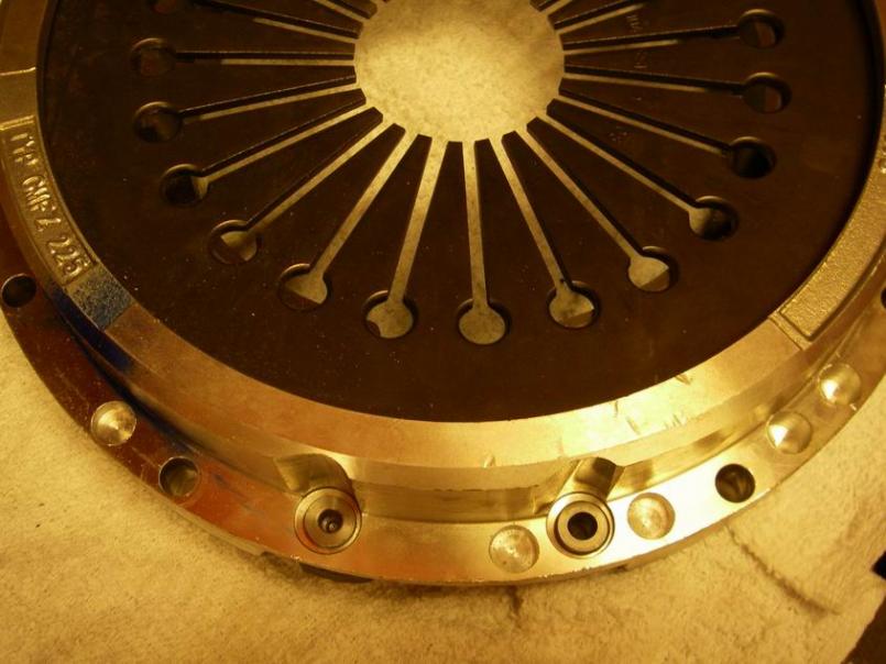
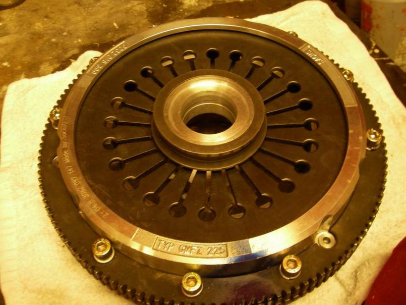
Attached image(s)
Posted by: jt914-6 Sep 24 2010, 05:10 AM
Filling up yesterday. Very cool pump display. 911 Turbo!
Ron......that's a '72 911 and they are putting gas in the oil tank......that's why it was changed and only that way in '72 only.....
Posted by: Jeff Hail Oct 17 2010, 12:10 AM
Damn Red Heads again. This one showed up at 3:00am and didn't leave for two days. Made all sorts of racket. They have an odd Narcissistic sense of entitlement. Go away!!!!!!!!!!!!!!Enough.......
Attached image(s)
Posted by: Jeff Hail Oct 17 2010, 12:12 AM
Made some room in the shop. Enough to fend off garage fever.
Cut off the old left outer console.
Attached image(s)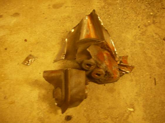
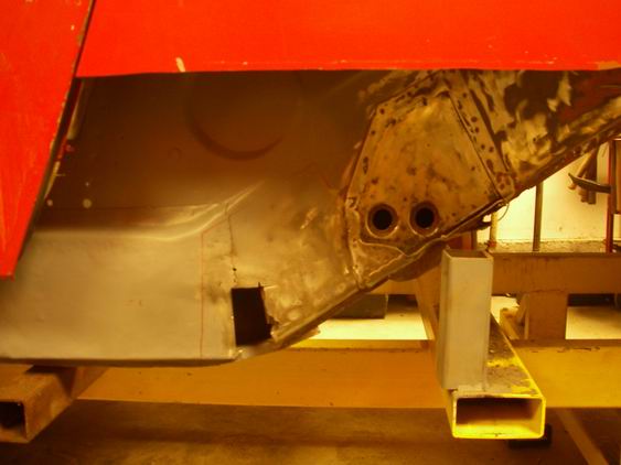
Posted by: Jeff Hail Oct 17 2010, 12:16 AM
Measure everything nine times. Remeasured again and triangulated again from every control point. Used Chris's supplied templates which so far are dead nuts.
Its cutt'n time.
Attached image(s)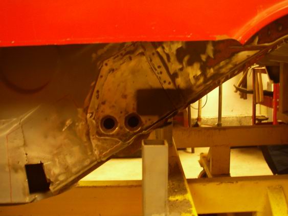
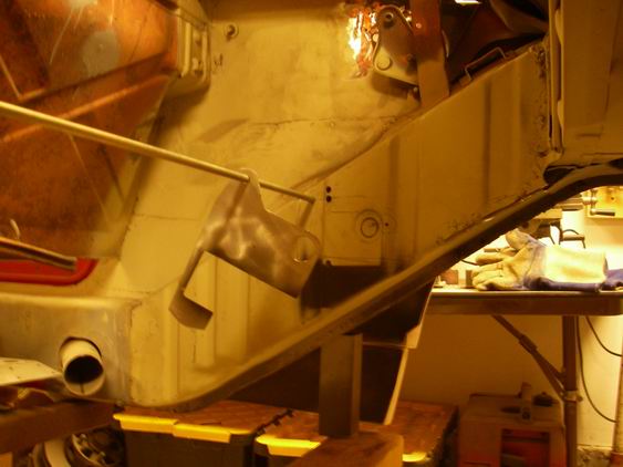
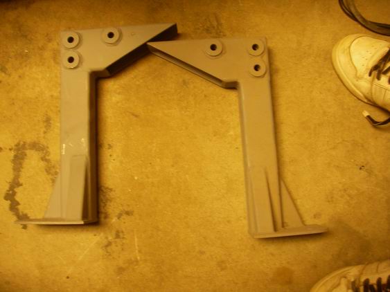
Posted by: euro911 Oct 17 2010, 06:30 PM
I never get rid of anything it seems ...
... hair color doesn't necessarily make the situation any better, or worse - women are women. 
Don't know how I missed this before. Excellent thread.

Posted by: Jeff Hail Oct 18 2010, 08:45 PM
Product Placement (of the Foley kind)
Left pickup test fit...
Funny thought.. the rear suspension hardware was one of the first box's packed away when I tore down the car. Smartly labeled took me just a minute to find those 3 console bolts.
Attached image(s)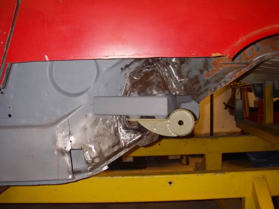
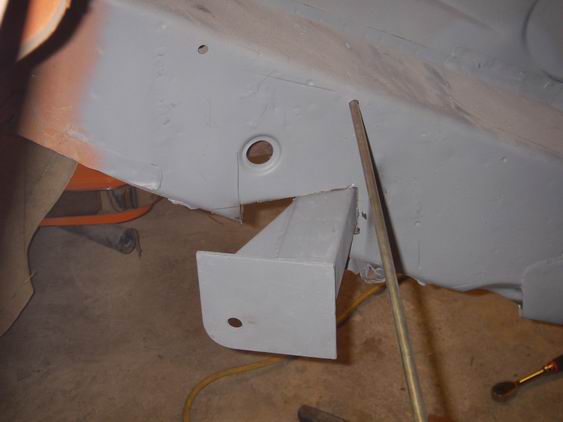
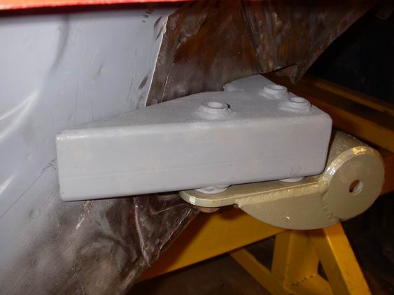
Posted by: Jeff Hail Oct 19 2010, 10:15 PM
Cut out the right long and test fit the right pickup.
Dimensionally width wise its less than 1mm and height side to side is dead nuts.
Took some measurements in process and need to move the pickups forward 5mm to correct the wheelbase length to spec.
(Another plug for Mr. Foley and his precision. I call it Lana but he deserves the mention - Thanks Chris!!!!!!!!)
Attached image(s)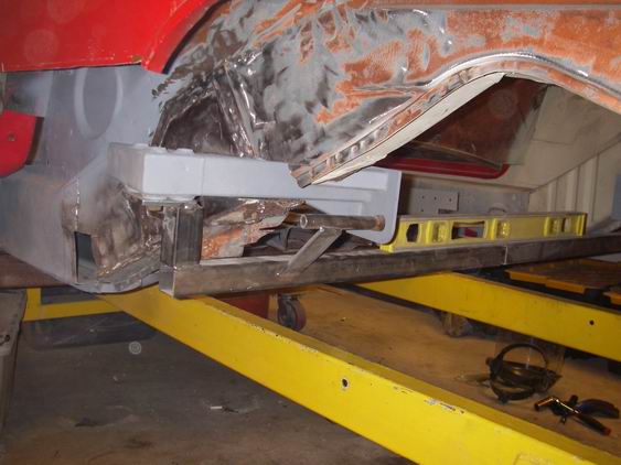
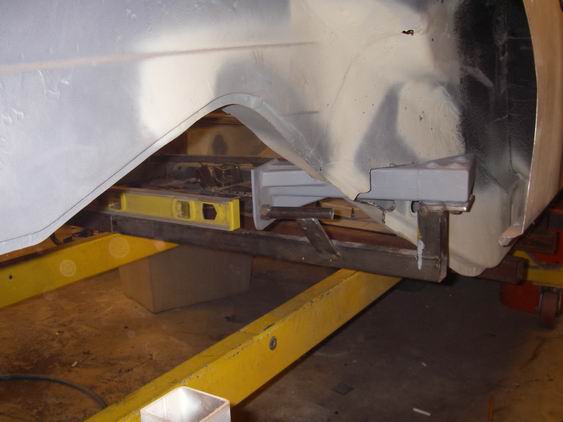
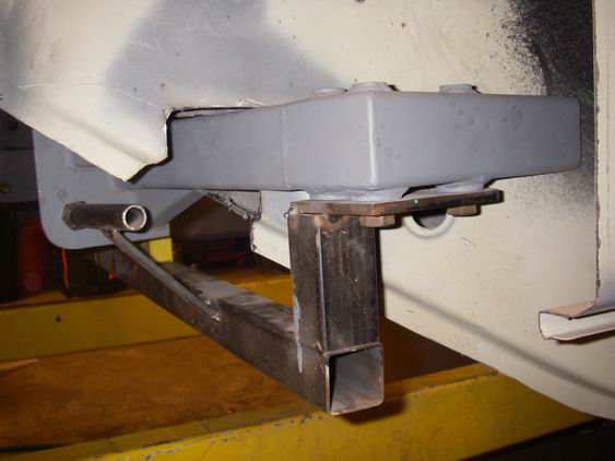
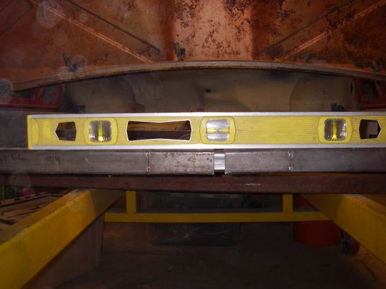
Posted by: Jeff Hail Oct 19 2010, 10:24 PM
Moving the pickups 5mm forward to match factory wheelbase base will also separate the pickups by the desired 1/2 inch (1/4 inch per side). This will result in a total 1/2 inch wider track over stock. (think ahead?? wheel spacers maybe/ maybe not with 9 inch rear wheels). Worry about that when I get there. Also with a 3.2 six a little bit to spare is a plus.
Attached image(s)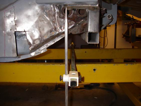
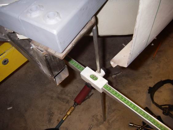
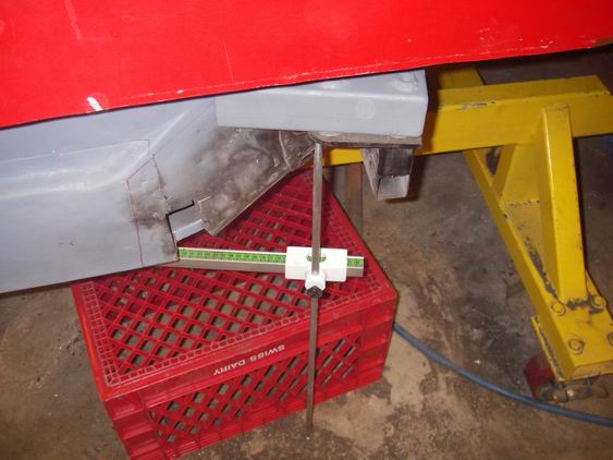
Posted by: Jeff Hail Oct 31 2010, 01:32 AM
Foley Pickups squared and tacked in.
So.... I need to build a Dummy Shock. How about a Multi-Tool instead???
Combo Wheel Bearing Puller -Dummy Shock ( 2 Inch Adjustable)
Attached image(s)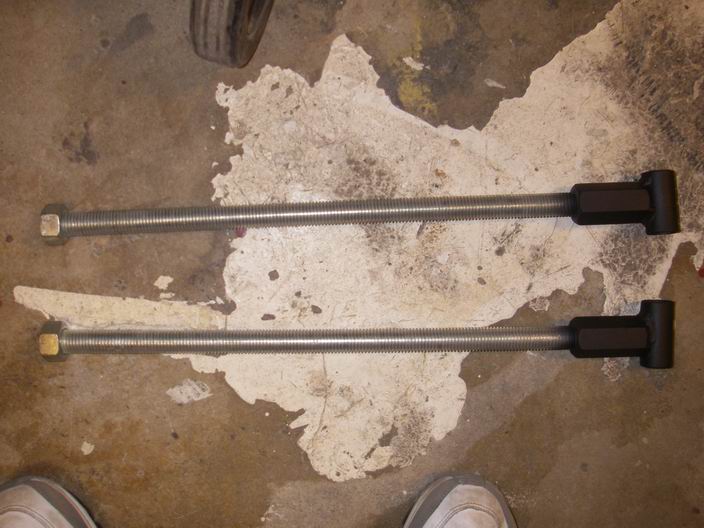
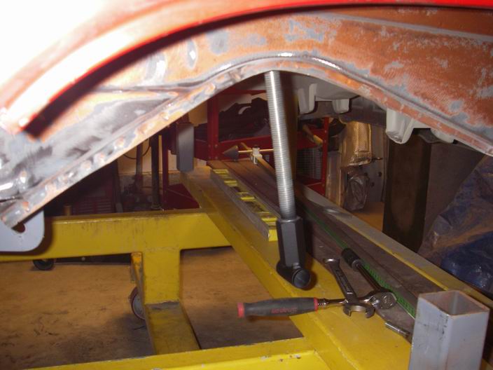
Posted by: Jeff Hail Oct 31 2010, 01:36 AM
Went to trial fit the control arm... and snapped the zerk fitting.. Stuff happens..oh well.
Need to trim a bit off the long anyway to clear the pivot axis of the arm as it sits 2 inches higher now.
Attached image(s)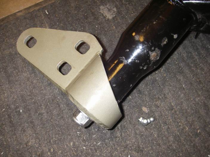
Posted by: Hontec Oct 31 2010, 03:12 AM
Amazing work!! I love this thread!
Posted by: Jeff Hail Nov 1 2010, 10:31 PM
Trimmed the longs enough to mount the arms. Wheelbase is dead nuts. Total increase in track width is 24mm (12mm each side).
Checked camber without any shims. Left rear is 1-3/8 degree. Right rear is 1-1/2 degree.
Wiggle room. I'd rather have more camber without shims than less so I will tweak the left rear inner pickup downward prior to final burn in.
I will need to pull the hubs into the bearings next. To check the toe I would like to mount wheels so I can measure bead to bead.
Attached thumbnail(s)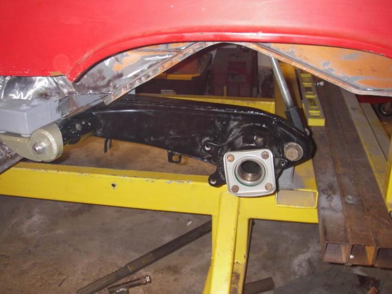
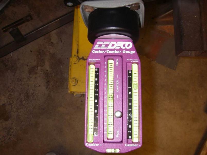
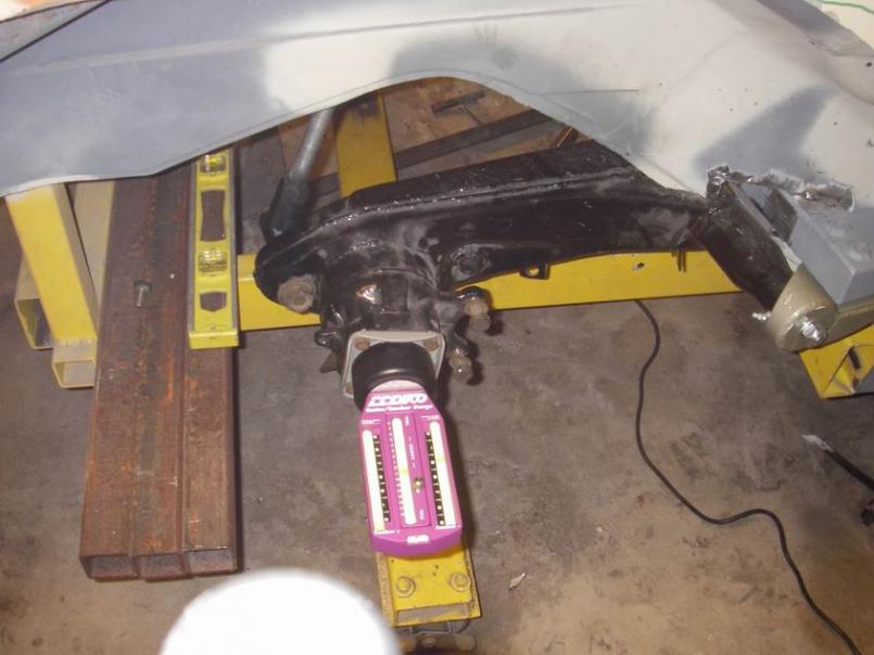
Posted by: kg6dxn Nov 2 2010, 07:02 PM
Maybe I missed something. Why are you moving the trailing arms out? Great work by the way.
Posted by: Eric_Shea Nov 2 2010, 10:29 PM
Mr. Hailpern, Hale-Bopp will be back before this thing is done! Worse yet... "my" car might be done before this one!!
Hurry up damn it and... don't blame it on the redhead! 
(keep up the good work chief... always an intriguing thread)
Posted by: Jeff Hail Nov 2 2010, 11:30 PM
Love you too Eric!!
Posted by: Jeff Hail Nov 2 2010, 11:35 PM
Pulled the frozen 911 hubs into the bearings. But first applied thread lock and torqued the bearing retainers. Everything that gets torqued to spec gets marked. No hindsight and oh Shi# did I do that crap? Cant forget the 5mm spacer.
Attached thumbnail(s)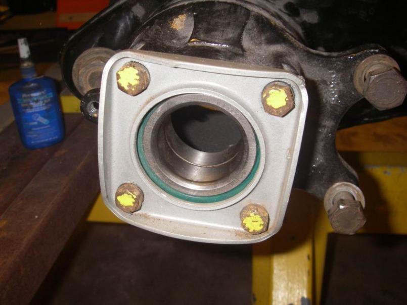
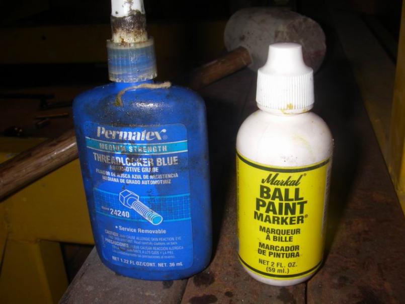
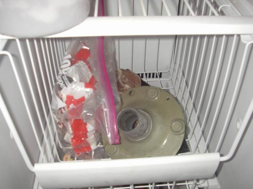
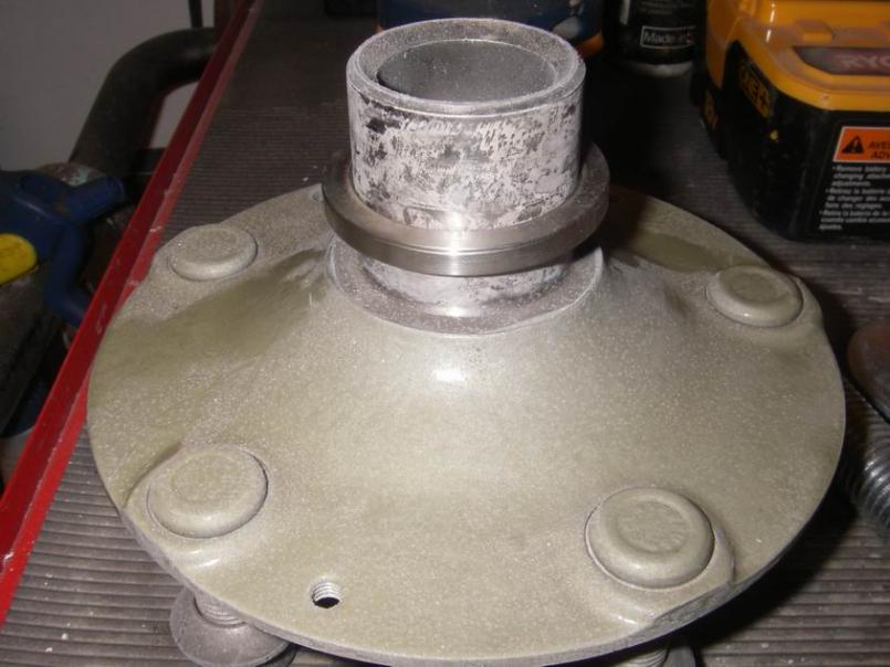
Posted by: Jeff Hail Nov 2 2010, 11:36 PM
In
Attached thumbnail(s)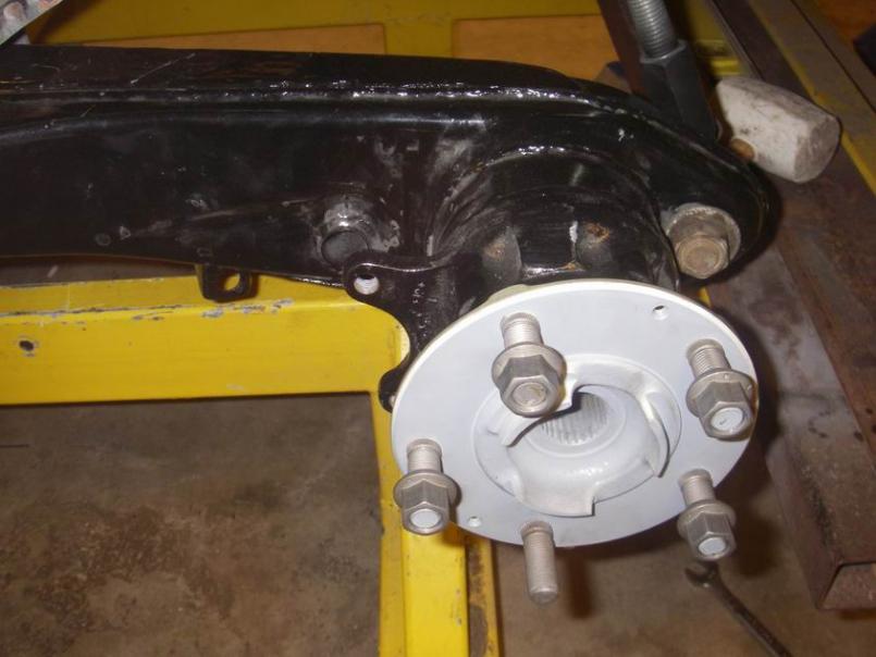
Posted by: Jeff Hail Nov 2 2010, 11:37 PM
Toys in the Attic
Attached thumbnail(s)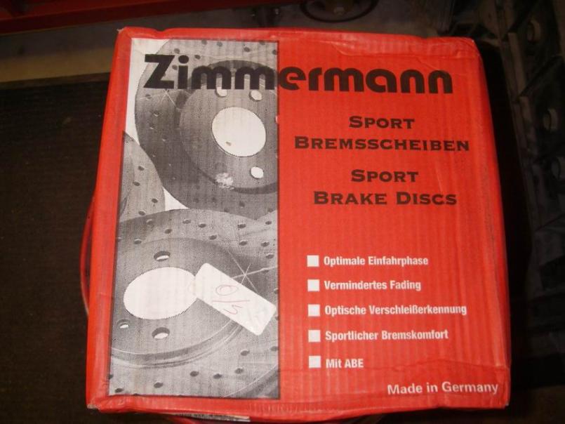
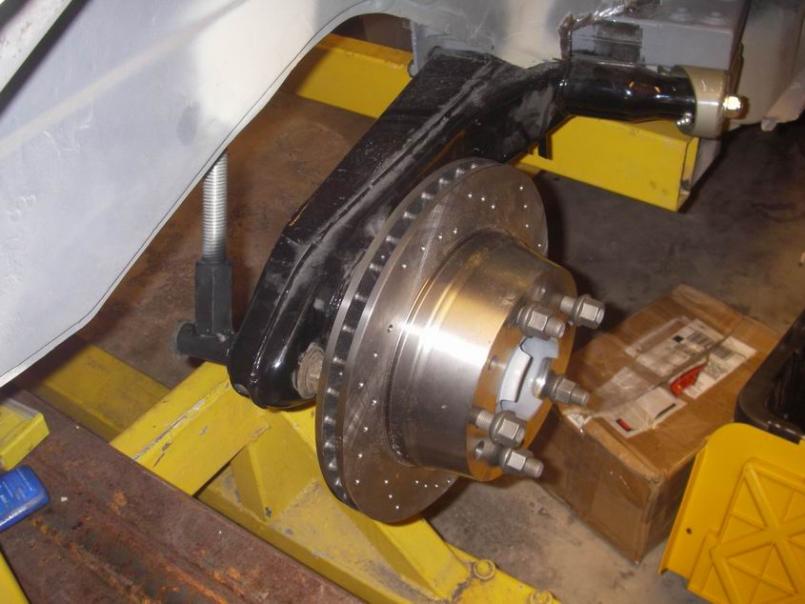
Posted by: Jeff Hail Nov 2 2010, 11:39 PM
Eric?? Eric?? Leave me alone I am busy.
The right side with qtr cut for the fat ass.
Attached thumbnail(s)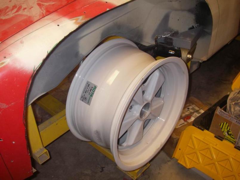
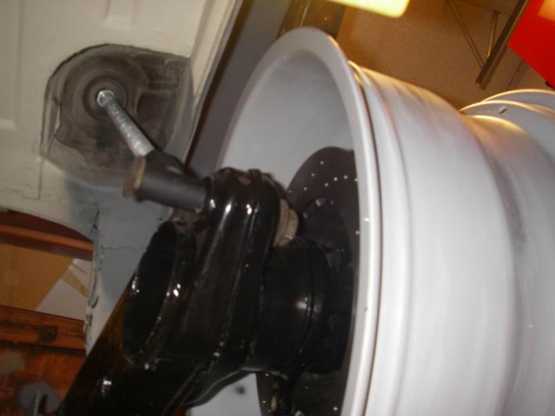
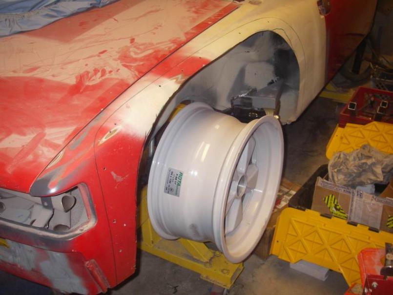
Posted by: Jeff Hail Nov 2 2010, 11:40 PM
The left side (un cut wheelwell).
Big difference!!
Eric?
Attached thumbnail(s)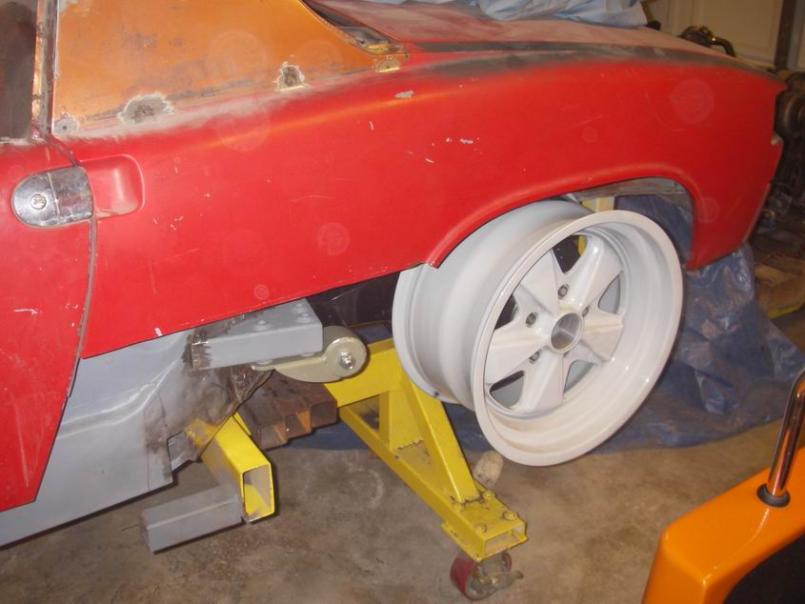
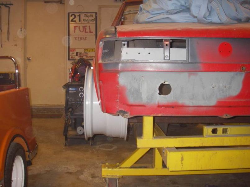
Posted by: Jeff Hail Nov 2 2010, 11:43 PM
Temporary fit.
I am happy and still have room to spare at the flare and inner wheelhouse.
Only means one thing... GO WIDER!!!!!!!!!!!!!!!!!!!! That's already a 17X9 wheel..
Attached thumbnail(s)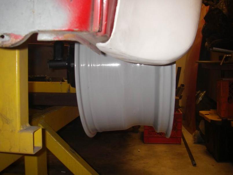
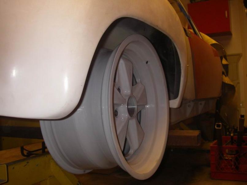
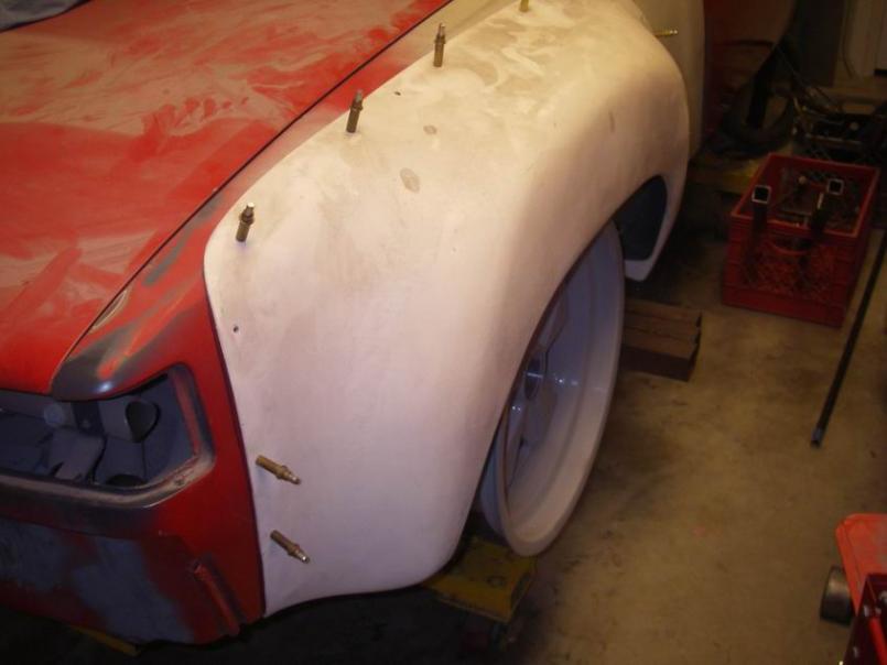
Posted by: Jeff Hail Nov 2 2010, 11:45 PM
Maybe I missed something. Why are you moving the trailing arms out? Great work by the way.
Yup!
Posted by: Eric_Shea Nov 3 2010, 09:25 AM
The Redhead says "Mmmmmmmm... Hubs and bearings for dinner tonight!" 
Posted by: Jeff Hail Nov 3 2010, 09:37 AM
That even looks like her!!!!!!!!!!
Cute! The girl Eric, the girl.
Posted by: kg6dxn Nov 3 2010, 10:35 PM
Maybe I missed something. Why are you moving the trailing arms out? Great work by the way.
Yup!
That did not answer my question. Why?
Posted by: Jeff Hail Nov 6 2010, 12:23 PM
I am only pushing the track width out 12mm per side at the suspension control points but in a nutshell…
A wider track on semi trailing geometry will increase the roll center at that end of the car, thus making it softer in roll (less body roll). This is because the car's CG will not change, and thus the vertical distance between the CG and the roll center at that end of the car will increase, kind of like using a torque-wrench with a longer handle that pivots at the roll center. A wider track will tend to reduce the load transfer to the outside when cornering, which in general will increase cornering ability since more traction is gained from the inside tires. It is important to maintain an optimum ratio between the front and rear tracks as a means to managing the load transfer from the front to the back with resulting balance between the two ends of the car. Wider track width can achieve a result similar to lowering the center of gravity height, less weight transfer allows the inside to carry more of the load, generate more total traction for the car. Notice I said similar because CG is another aspect. Multiply tire vertical load by the tire performance curve, = available cornering traction generated by the tire. The outer tire is heavily loaded and gains less traction per pound of load added; the inner tire will generate more traction per pound of vertical load. Effectively gaining more total cornering force.
Other ways to increase track width that I am not a fan of.
Wider than optimal wheel and tires:
Additional weight. Too much tire is not an effective gain. Suspension and body limitations.
Wider wheels with low offset:
Moving the wheel-tire centerline out will not change the suspension geometry, but it does change the relationship between the tire and the suspension. Moving the wheels out will reduce the effective rate of springs. Increased loading of the wheel bearings since the load will be cantilevered further out which increases the possibility of deflection/ twisting of the trailing arm under high loading.
Wheel spacers: (very thick ones)
Rear:
Same increased loading of the wheel bearings since the load will be cantilevered further out. Additional weight of the spacers and longer wheel studs.
Front:
Widening the front track using spacers increases the front scrub radius, which can increase the steering effort and cause kickback. It also increases the load on the bearings.
Other:
A smidgen extra access to the valve covers on the six.
Posted by: ghuff Nov 6 2010, 02:58 PM
I had to stop in this thread to say you rule. This is excellent, and a lot of work.
Posted by: MrHyde Nov 14 2010, 08:25 PM
Question about the new rear suspension pickup setup you're putting in....
Would this setup be " worth the effort " for anyone that has to do the rear long, wheel house repairs that you had to do on your car ?
The reason I ask is because I am going to be replacing the rear wheel house and rear long on my car and if I have to remove the outer suspension console anyways.. upgrading the whole setup might be worth a look..
I'm undecided weather I'm going to put on the fender fares or not and I most likely wont go over 150 ish HP with mostly daily driving with a few track days for fun..
Cheers and keep up the good work.. its been a informative read for sure. !
Posted by: Jeff Hail Nov 14 2010, 10:45 PM
Would this be worth the effort? Absolutley it would be BUT if you are not raising the pickups there might not be enough meat at the bottom of the long to support the custom pickup from a factory control point perspective.
You could still use the 2inch raised pickup and keep the stock ride height without any issues.
The benefits of Chris's pickups: No flex, no rust, no worrying whats inside the existing pickups (rusts from the inside out), adjustability to lower the ride height while keeping the original geometry. Ability to add track width. No deflection between the OEM inner and outer console as the pickups are one integral unit. No cracking of inner ears.
So far it is the only alternative on the market that is simple and straight forward this side of of tube frameing.
Ive looked at Keith's setup and it's a lot more work with more room for error if you ask me.
http://www.vehiclecraft.com/pictures/Cust_cars/Peare/index.htm
Posted by: MrHyde Nov 15 2010, 07:04 AM
I looked at the link you posted.. You're right.. it does sound like a lot more tricky setup than Chris' one... hmm You mention you could still have the pickups welded in 2 in' up and still have stock ride height.. It might just be early to wrap my head around this but how would that be possible... while keeping the propper geometry ?
Posted by: Jeff Hail Dec 21 2010, 12:16 AM
The Redhead says "Mmmmmmmm... Hubs and bearings for dinner tonight!"
Still haunts me Eric
Posted by: Jeff Hail Dec 21 2010, 12:22 AM
Busy with holiday cheer and other peoples stuff.
A few minutes to play.
The pickups are where they need to be. Lets perform some more alchemy.
Started installing the reinforcements. Left side outer first... because if its going to shrink I'd rather the camber go more negative than the other way. Then the inner.
I still have to trim some more at the bottom and fit those reinforcements.
Ran out of C02/Argon. No gas stations open this time of night.
Attached image(s)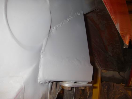
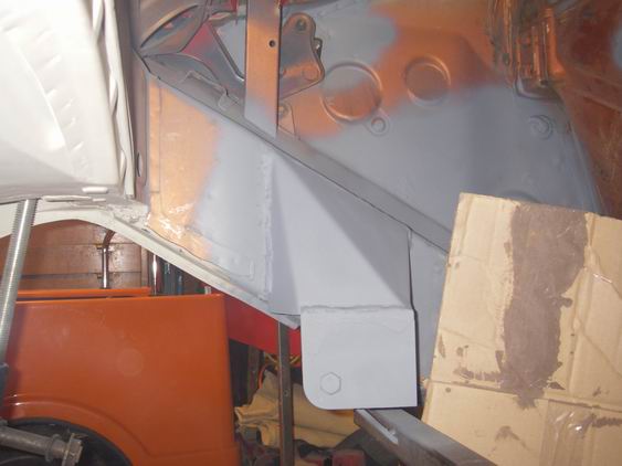
Posted by: Jeff Hail Jan 3 2011, 11:55 PM
RT side in!!!
Good feeling when the pickup fixture just drops out and doesnt have to be wrestled.
Attached image(s)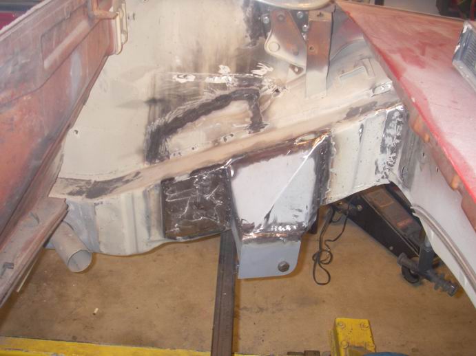
Posted by: nsr-jamie Jan 4 2011, 09:13 AM
This is my favorite thread, I just spent the last 4 hours reading it all from page one!! Truly excellent !!! I wish I had you working on my car. Please keep up the incredible work. I learned a lot reading through the entire thread, thank you
Posted by: Jeff Hail Jan 14 2011, 12:51 AM
Non stop!
Attached image(s)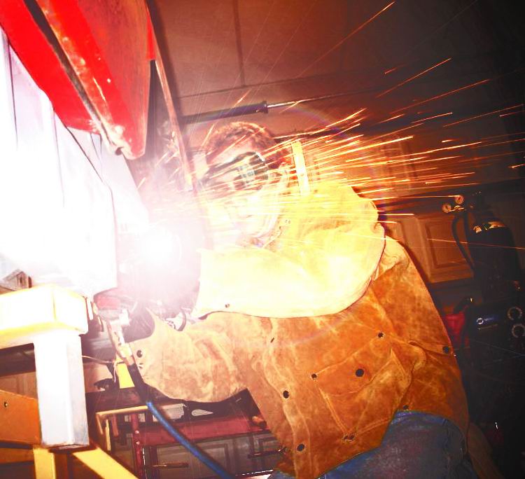
Posted by: Jeff Hail Jan 20 2011, 02:16 AM
Finishing up the pickups. Lots of weld grinding and fitment of the closing plates. This is where I wish I had a TIG instead if a MIG.
By the way the price Chris Foley charges to install these is a bargain considering the labor. I think he should get twice as much based on the fitment, welding, grinding etc.
I am just about done. One last piece to weld in. I buddy of mine shows up in his brand spanking new 2011 German Turbo P-Car and wants me to install an aftermarket muffler. I turn him down! He asks why? I respond because if I keep doing stuff for other people my stuff doesnt get done!!!!!!!!!!!!!!!!!!!!!!!!!!!!!!!!!!!!!!!!!!!!!!!!!!!!!!!!!He gets it and understands.
I am fitting pieces to weld and he says DONT DO THAT. By the way he is a real honest rocket scientist. He makes bus's fly. He then grabs a piece of cardboard and traces out a template. DO IT LIKE THIS.I hate it when he does this. He doesnt know jack about cars except how to write the check when he buys the latest German Hot Rod. This guy plays with things that fly fast and well he makes me think in a challenging way because he's smart...really smart because he is a airframe engineer and has more degree's than a thermometer.
He says "car doesnt have a roof... it flex's a lot. Flexing is not good". Why not tie this reinforcement into the torque box? Ding, ding light bulb goes off and I have to admit he is right. So I make the change.
So a little product improvement "why I am in here". Fab a modified piece.
The original closing plate on top of the "improvement piece". Extends forward into the long. Makes sense.
Attached image(s)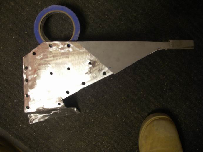
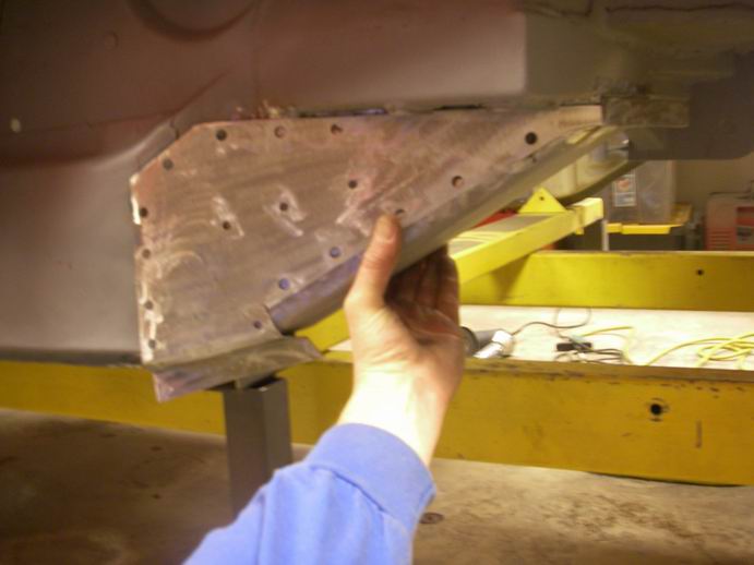
Posted by: Jeff Hail Jan 20 2011, 02:18 AM
Eric,
I really have been working. The other side.
Attached image(s)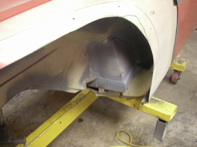
Posted by: Jeff Hail Jan 20 2011, 02:24 AM
Chris,
My friend really admired your pickups. He (quote) said..." simple, structurally sound design, robust and well thought out" after looking at the old factory stamped sheetmetal pickups. Like Mikey he hates everything BUT to get a compliment like that from him is real.
Posted by: Jeff Hail Jan 20 2011, 02:48 AM
For us old guys who wear reader/ progressive len's. I am really a young 45 years old.
Safety glass's with magnifiers. I swiped these from the rocket scientist in exchange for installing his exhaust. Took me thirty minutes to install the silencer that was really throaty (cool facter).
I put these on and WOW. Great for welding when your eyes are old and you have to lift your welding helmet to inspect your welds. They are available in 1.0, 2.0 and 3.0 power. I felt like Eddie Murphy... "I can see, I can see".
Goverment Services Pricing: $100.00 (sorry no toilet seat)
Granger/ AutoBody Toolmart $10.00
"There are Some Things Money Can't Buy. For Everything Else, there's stealing your rocket scientist pal's safety glass's". PRICELESS!!! He ain't getting them back!
Attached image(s)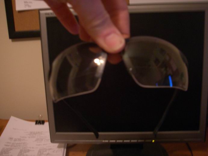
Posted by: Krank Jan 20 2011, 08:30 PM
And if you are working on something close just above your line of sight....wear them upside down. Yeah, I'm old too!
Posted by: Eric_Shea Jan 21 2011, 01:18 AM
Get with the program... 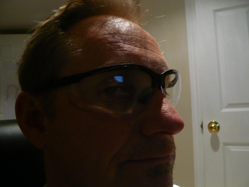
Posted by: Jeff Hail Jan 23 2011, 10:47 PM
Get with the program...
I'm trying Eric.
Posted by: Jeff Hail Jan 23 2011, 11:04 PM
A few hours spent today installing the outer reinforcement, finish grinding and tidying up the left side. I didn't like the condition of the pinch weld just forward of the pickup soooooooo I flat bottomed the entire rail. One big piece of 16 gauge steel shaped like a "C" , plugged, seamed welded from inside to underside to outside. Look's clean and stout. I will duplicate the same on the right side.
Attached image(s)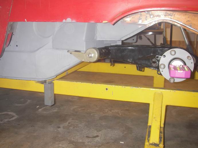
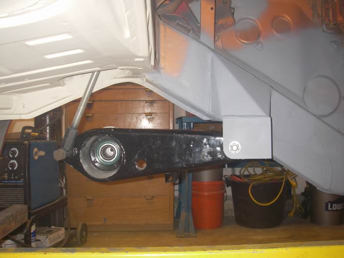
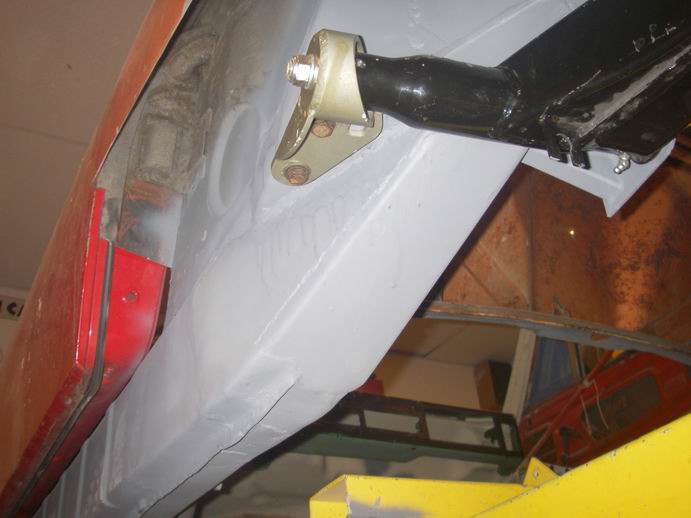
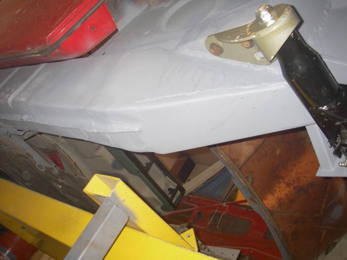
Posted by: Hontec Jan 24 2011, 04:05 AM
Nice solution! pickups not only look way better than stock!
Posted by: P.Rocket Jan 26 2011, 03:25 AM
This thread is briliant!
Very well documented.
A very useful tool for what I have in store.
My 15yo son and I just rolled the 73 914 into the shop last weekend, to lift it up on the hoist and have a look around to assess the extent of rust and poor previous repairs. Wow this will be one big project, for sure . Like I said to my son, atleast you'll know how to weld when we're done.
Thanks for the quality information.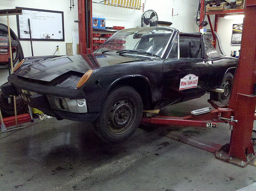
Posted by: Jeff Hail Feb 5 2011, 12:22 AM
While waiting for my date to arrive to go out for a bite I got bored.
Installed a backer plate behind the pillar. Then butt welded the lower lock pillar in.
The bottom is loose at the sill so I can shift it as needed when the sill goes in.
Didn't even get dirty!
Bon Appétit
Attached image(s)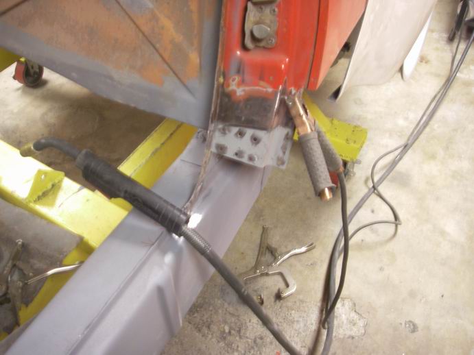
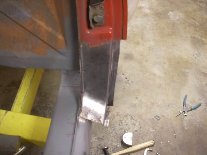
Posted by: sixnotfour Feb 5 2011, 11:26 AM
date "oh jeff you smell great ,what cologne do you have on ?"
"Metal Man"
Posted by: Jeff Hail Feb 5 2011, 11:59 AM
date "oh jeff you smell great ,what cologne do you have on ?"
"Metal Man"
Hugo Boss -Dark Blue
Accents my Miller 180
Posted by: Jeff Hail Feb 5 2011, 11:27 PM
Repeat of a previous hat trick except in reverse. A few tiny pin holes in the butt weld to fix later. I will have to stretch the bead area via hammer form a little as it sucked in from the heat. It happens.
Bottom of the lock pillar still left loose for wiggle room when I install the sill and final fitment.
Attached image(s)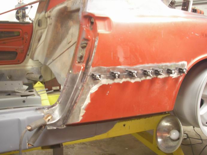
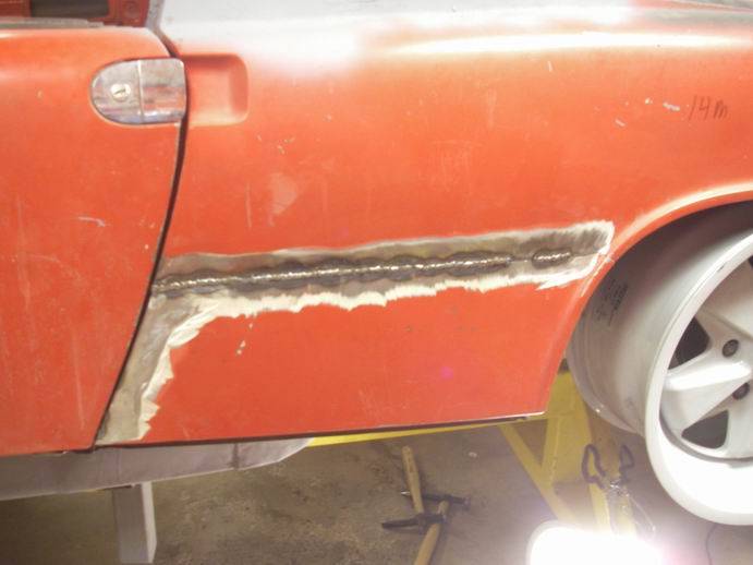
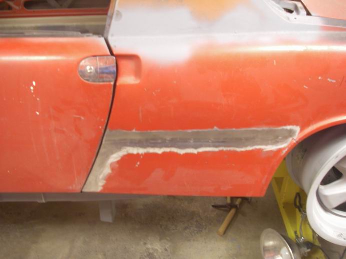
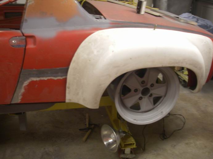
Posted by: Eric_Shea Feb 6 2011, 03:25 PM
Posted by: majkos Feb 6 2011, 10:22 PM
You make it look Soooo easy!
Posted by: Jeff Hail Feb 11 2011, 07:12 PM
Driver side sill in. Need to finish grind the plugs and pillar joint, then install the triangles.
Attached image(s)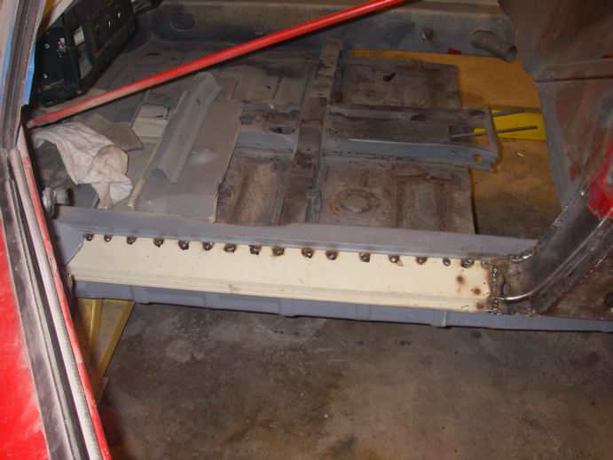
Posted by: Jeff Hail Feb 11 2011, 07:14 PM
Thats a floor Eric. Say ahh!
Attached image(s)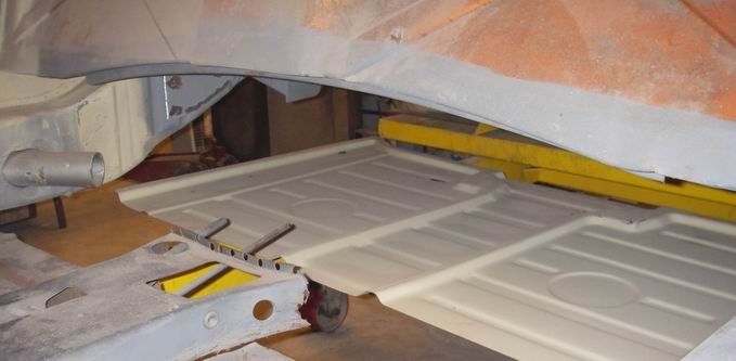
Posted by: Jeff Hail Feb 13 2011, 10:11 PM
Chipping away one piece at a time. Metal finishing on the sill and lock pillar done. Sill triangles installed. Deleted the dome light switch holes.
Thought I had some epoxy primer left (It's somewhere or maybe I am out) Sucks because I hate using etching primer on an area thats done and wont need to come back to until final prep for paint. Oh well it will sand off easily later.
Attached image(s)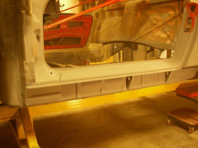
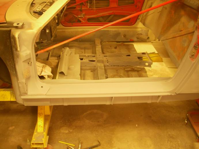
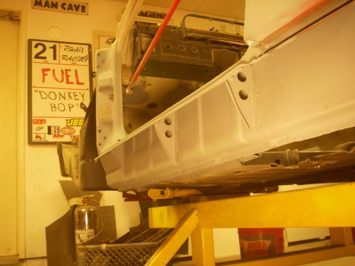
Posted by: ONTHEGRIND Feb 13 2011, 10:15 PM
I am doing alot of metal work myself and have etching primer that I used on my trunk what are the benefits of using the epoxy ?
Posted by: Jeff Hail Feb 13 2011, 10:19 PM
My good friend Victor Van Tress (1987 SCCA Nationals SSB champion winning 505 Turbo) snapped this photo a while back.
Awesome tow vehicle. Priceless pic. Makes you smile because you wonder what else does the owner have in his garage?
Attached thumbnail(s)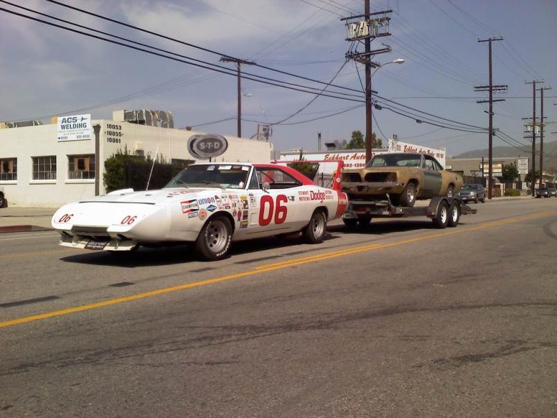
Posted by: Jeff Hail Feb 13 2011, 11:22 PM
I am doing alot of metal work myself and have etching primer that I used on my trunk what are the benefits of using the epoxy ?
Etching primer is good for bare metal. Its comprised of acid, zinc and binders. SEP will fend of surface rusting but it does not seal metal as epoxy does. Being my project sits sometimes I would rather not worry whats going on under the surface over time so I use epoxy primer. Personally I think epoxy has a better bite also.
Refinishing products are meant to be applied with time limits.. and not long intervals between application of say primer's and basecoats. In my experience etching primers and 2K primers are not and do not hold up unless colorcoat/ clear applications are done in short order as moisture can penetrate if let to sit. SEP and 2K primers have good adhesion properties if top coats are applied very soon.
Additionally if filler is being applied they can be done under or on top of epoxy primer. (this one is always open to debate). I personally would never apply filler over or under etching primer... as acid can get into and soften filler.
For me I prefer metal conditioning as a separate process.
Bottom line every paint manufacturer has a system with products and the order to be used in.
Posted by: Jeff Hail Feb 23 2011, 11:21 PM
Installed some new metal on the left side of the tunnel where the flange/ floor meet.
Trim, trim, trim and drill a bazillion spot welds. The left side floor crossmember has twice as many resistance welds as the passenger side. Some rust under the crossmember flange actually "rust welded" the floor together.
I might make new crossmember overlays if it doesnt come apart at the flanges easily. An air chisel will tear the flanges up and a hand spot weld buster is already doing that.
Attached image(s)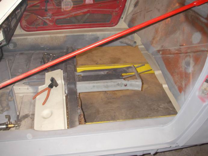
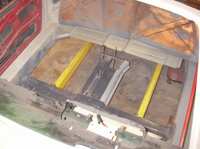
Posted by: krazykonrad Feb 24 2011, 10:48 AM
"rust welded"
Don't cut out the rust welds. Those are original from the factory!

Konrad
Posted by: Jeff Hail Mar 7 2011, 05:03 PM
A few more modifications to the early firewall. Closed off the heater cable tube holes and airtube exits from the inside.
Early/ Late lower firewall:
The brake presure regulator and brake line exit sits farther to the left on the early firewall. I think I will leave them where the early panel locates them. Not sure if the later location will interfere with the 3.2 but I don't want to find out later.
Lower firewall final fit up done. Held with Cleco's. Inner reinforcement (AA) halves welded together to create a single panel...easier to assemble.
Attached image(s)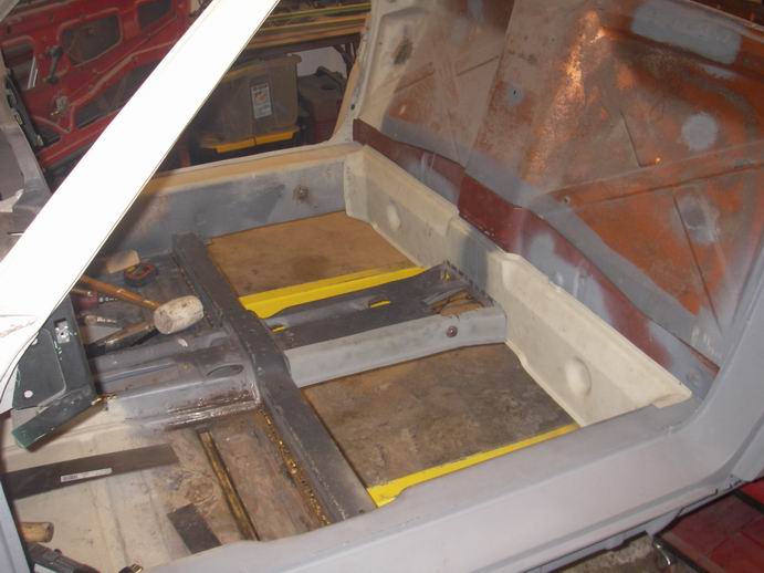
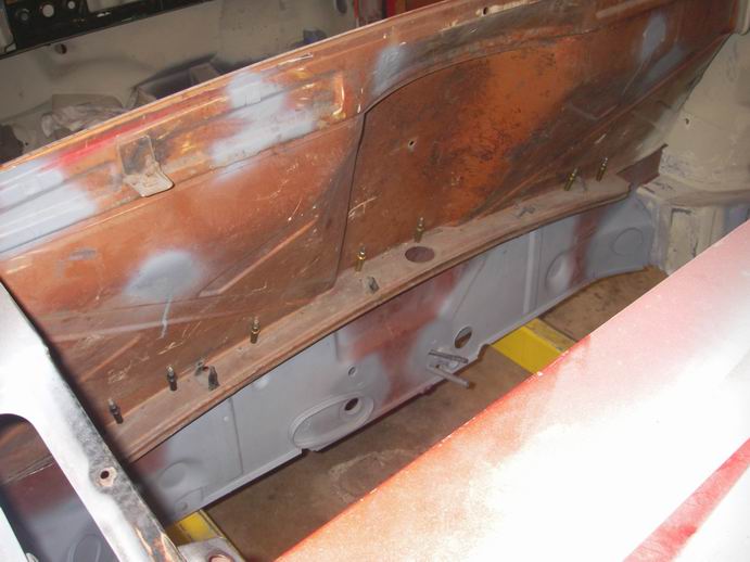
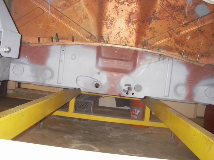
Posted by: Jeff Hail Mar 7 2011, 05:06 PM
Next I will fit the floor and trim as needed. Take it all apart and punch the holes for the plugs.
Posted by: Jeff Hail Mar 7 2011, 05:08 PM
"rust welded"
Don't cut out the rust welds. Those are original from the factory!
Konrad
I missed that Konrad. You're a funny guy! I wonder if "Rustone" was a factory color code option?
Posted by: Jeff Hail Mar 21 2011, 11:55 PM
Bunch of little things to tidy up, fabricate... before I button the floor up....
1)FABRICATE THE PASSENGER SIDE TUNNEL REPAIR PART.
Fabrication is easy. Doing it twice with opposites is a challenge. Even know the parts are dimensionally symetrical they are not the same. ( Cutouts, notches etc)
Came out a beautiful piece of metal !!!
Attached thumbnail(s)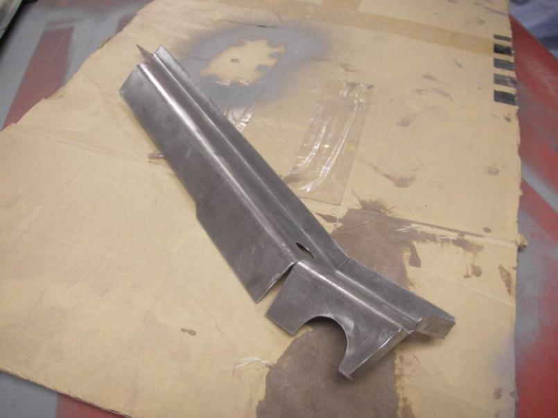
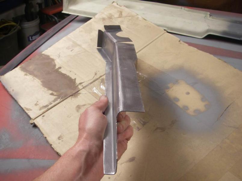
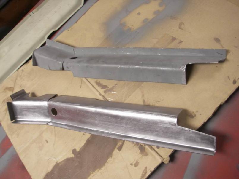
Posted by: Jeff Hail Mar 21 2011, 11:56 PM
Now thats a SHIFT knob !!
Whatcha think?
Attached thumbnail(s)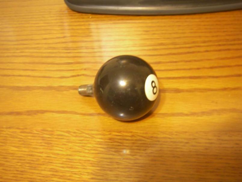
Posted by: KELTY360 Mar 22 2011, 12:13 AM
Now thats a SHIFT knob !!
Whatcha think?
I can get behind that.
Posted by: Hontec Mar 25 2011, 12:26 PM
I just read your topic and maybe I read over it, but the lower part of the firewall on the engine side, who makes that panel? AA or restoration design or did you manage to get an original one?
Thanks and I love the way you're doing this, extremely nice work!!!
Posted by: dpires914 Mar 26 2011, 09:33 AM
Bunch of little things to tidy up, fabricate... before I button the floor up....
1)FABRICATE THE PASSENGER SIDE TUNNEL REPAIR PART.
Fabrication is easy. Doing it twice with opposites is a challenge. Even know the parts are dimensionally symetrical they are not the same. ( Cutouts, notches etc)
Came out a beautiful piece of metal !!!
Nice work Jeff. What gauge steel did you use by the way?
Posted by: Jeff Hail Apr 6 2011, 08:58 AM
I just read your topic and maybe I read over it, but the lower part of the firewall on the engine side, who makes that panel? AA or restoration design or did you manage to get an original one?
Thanks and I love the way you're doing this, extremely nice work!!!
The lower outer firewall is a New Old Stock panel for an early car.
Posted by: Jeff Hail Apr 6 2011, 08:59 AM
Bunch of little things to tidy up, fabricate... before I button the floor up....
1)FABRICATE THE PASSENGER SIDE TUNNEL REPAIR PART.
Fabrication is easy. Doing it twice with opposites is a challenge. Even know the parts are dimensionally symetrical they are not the same. ( Cutouts, notches etc)
Came out a beautiful piece of metal !!!
Nice work Jeff. What gauge steel did you use by the way?
16 guage
Posted by: obscurity Apr 6 2011, 09:34 AM
I just read your topic and maybe I read over it, but the lower part of the firewall on the engine side, who makes that panel? AA or restoration design or did you manage to get an original one?
Thanks and I love the way you're doing this, extremely nice work!!!
The lower outer firewall is a New Old Stock panel for an early car.
Where did you find the part? Was it pricey?
Posted by: krazykonrad Apr 8 2011, 09:05 PM
Jeff-
Your level of craftsmanship is incredible! Every time i see this thread, I'm just amazed.
Konrad
Posted by: Jeff Hail May 7 2011, 12:05 AM
A bit of a hiatus after two back to back surgeries. Nothing major just time away for healing.
I have never been a fan of articulated headlamps. Loss of form when raised and aerodynamically handicapped. Added weight etc, etc, etc. I have been on the hunt for three years for a viable compact alternative to the original.
Hella offers a solution but not econonical at $1400 a pair including ballast. F that!
I have seen flush mounted lamps that frankly look and are cheap substitutes for a functional alternative to the original.
CRITERIA:
1) A more powerful lighting solution.
2) Improved illumination with less power draw on high beam than the original sealed beams
3) Cost effective and easy to fabricate/modify.
4) Able to fit into the original lamp bucket without cutting original material away (in case I ever want to revert back to the pop ups)
5) Somewhat plug and play.
Enter Bi-Xenon lamps: ake Daimlers "Xenarc" projector headlamp
A compact and short Bi-Xenon projector assembly
Both the 2010 SL55 and E class use the same Xenon projector assembly. The lamp assemblies are completly different as the SL55 has adaptive (pan, tilt) servos BUT the actual projector inside the lamp is the same identical unit. A friend at a Benz shop has damaged assemblies all day long BUT the projector is always OK.
I take a few junk damaged headlamp assemblies home and start destroying them for the guts. The high end cars have about 180 individual pieces that make up ONE headlamp assembly. I am only after the projector with the shutter actuator. Bi-Xenon lamps do not have a low and high beam. The lamp is always on. What differentiates high and low beams is a shutter or brow that blocks off a partial amount of light like a camera lens shutter or iris.
These are light weight, short and compact. I only need to fabricate a housing like the 944 flush headlamps and lens. Make sure it is servicable and sealed.
If Lamborghini could get away with using 92 Nissan 300ZX headlamps on the Diablo I can do this easily. (bet you never knew that)
Attached thumbnail(s)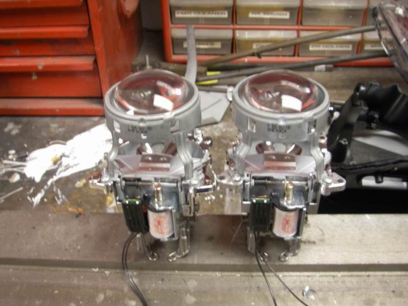
Posted by: Loser_Cruiser May 21 2011, 08:58 PM
any updates?
Posted by: Jeff Hail May 21 2011, 10:39 PM
any updates?
Nope... busy elsewhere.
Posted by: saigon71 May 23 2011, 02:38 PM
Awesome work Jeff! I have learned a lot from this thread.
Posted by: Jeff Hail May 25 2011, 11:18 PM
A little time to play last night. Been busy everywhere else.
The rear portion of the tunnel is done and welded. Spent a lot of time fitting the floor to the tunnel flanges and lower rear firewall. Lots of trimming here and there, leveling and self tapping screws for positioning. Then take it all apart again for the last time before I weld everything up.
1)Still need to weld in the mid bracing for both the clutch and throttle cable tubes rom the underside. Need to pickup some copper rod to shove inside the tubes so I dont blow holes.
2) Contemplating moving the shifter tower back a couple of inches.
3) Need to media blast the inside of the tunnel to remove the last of any scale.
Attached image(s)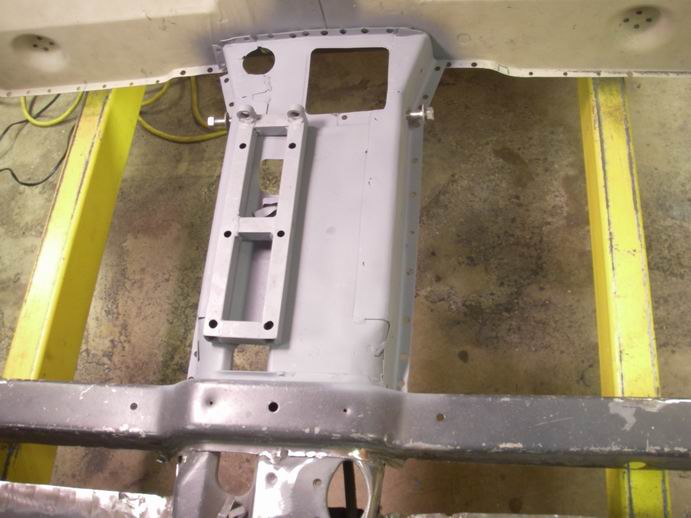
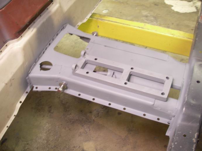
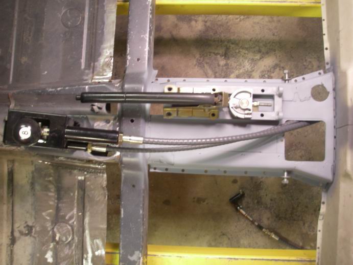
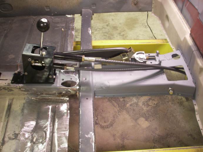
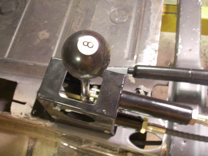
Posted by: speed metal army May 25 2011, 11:52 PM
Now thats a SHIFT knob !!
Whatcha think?
I think youre on the right track.Fu**in A!
Posted by: Loser_Cruiser May 26 2011, 04:36 PM
Lookin good, I'm excited to see your lighting solution.
Posted by: enderw88 May 26 2011, 06:16 PM
If Lamborghini could get away with using 92 Nissan 300ZX headlamps on the Diablo I can do this easily. (bet you never knew that)
I had to see it to believe, wow!
Posted by: Jeff Hail Jun 3 2011, 12:00 AM
My neck and left shoulder are killing me. Can't keep a good fabricator down.
The tunnel braces for the throttle and clutch tubes are fab'd and installed. Sorry no pics.. Ooops.
Fab'd some other parts. I hate buying stuff that can be made and love making stuff that can't be bought. Access to a 50 ton press is helpful.
Name those parts?
Attached thumbnail(s)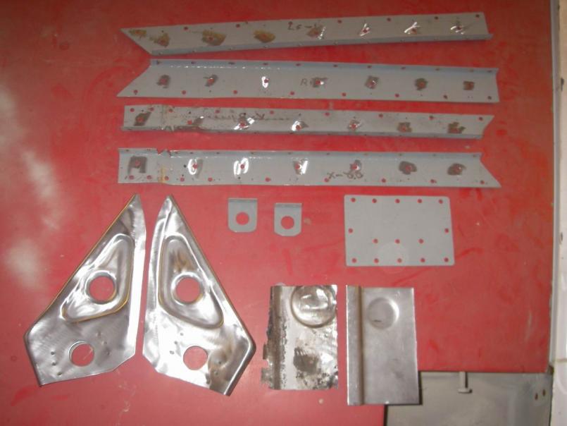
Posted by: majkos Jun 3 2011, 07:07 AM
I LOVE the near "donut holes" shelf
(Don't know what to call 'em)
Better than original
Posted by: Scott Schroeder Jun 3 2011, 03:43 PM
Now thats a SHIFT knob !!
Whatcha think?
Is that a real pool ball? If so, bad bad bad bad bad bad bad bad idea - please do not use that. I did the same thing on a 1981 full size blazer - built the thing in shop class in high school around 1984. I can still see some of the scars from the 20+ stitches in my hand when it shattered 3 months later while driving. Find a fake/wood ball - dont use a glass/ceramic.
Ugh. I remember having to call my parents from a pay phone to come get me in a parking lot and take me to the ER. Had a hand full of glass, a shifter covered in shards and blood all over the carpet and seats.
Posted by: Jeff Hail Jun 11 2011, 11:02 PM
Actually the 8 Ball came with the car. I think it passed the test of time. Its a real shift knob not off a table.
Posted by: Jeff Hail Jun 11 2011, 11:03 PM
Guess that part? Hint: Qtr panel.
Attached image(s)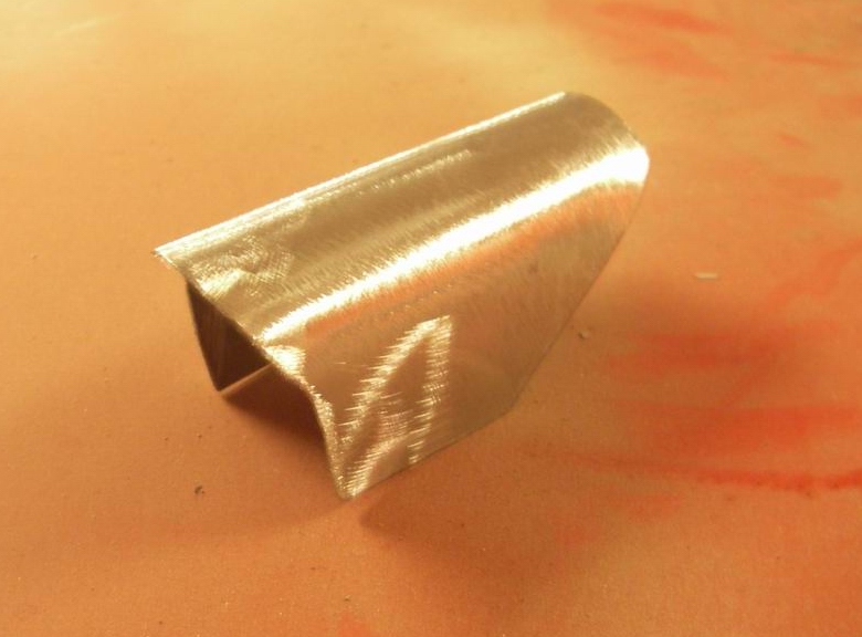
Posted by: Jeff Hail Jun 28 2011, 08:02 PM
I guess no takers on: "Guess that part".
The prior owner had the left quarter panel replaced at one time. I assume this was done probably when the car was fairly new judging by the grey filler and some brazing. Space age microspheres (Dynalite used red hardner and the filler ends up pink) so I know its old old work.
Well the bodyman used an air chisel here and a Sawzall there. He cut right through the vent duct and never bothered to repair his fine error.
That weld you see at the lower rt corner of the photo is where I removed some brass at the pinch weld. I didn't like the way it looked.
Attached thumbnail(s)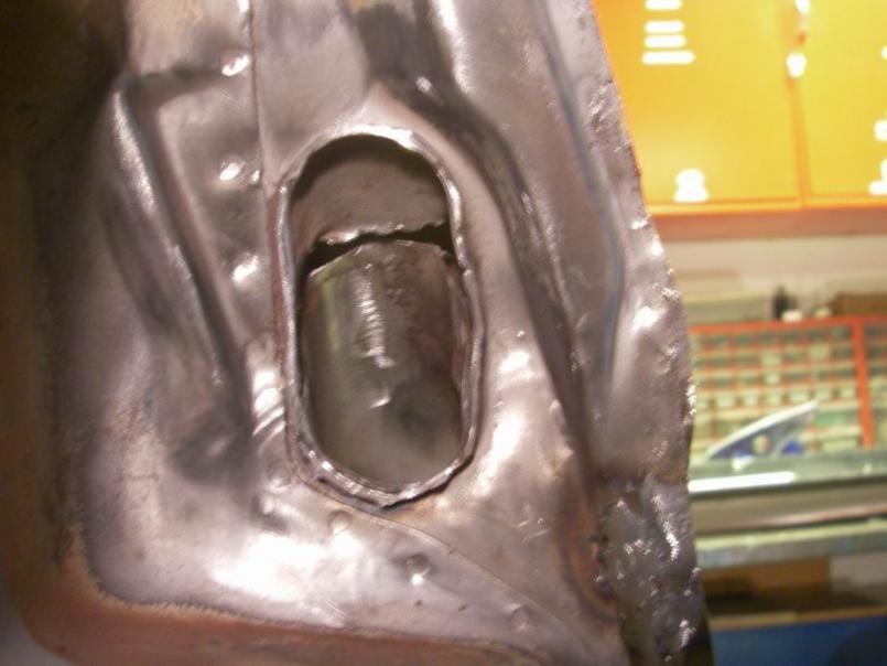
Posted by: Jeff Hail Jun 28 2011, 08:10 PM
My conundrum was how to repair or replace it with the quarter panel still on the car? No room for tools up there.
So grind out the gash flat and fabricate a piece. Used a drum sander on an extension to get in there. Sand blast it bare.
Attached image(s)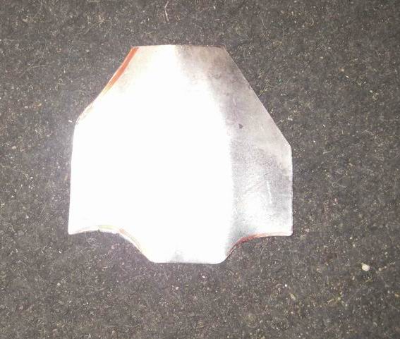
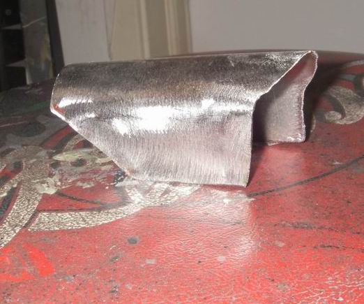
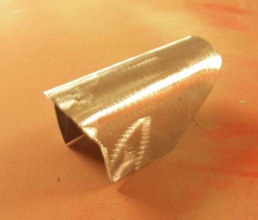
Posted by: Jeff Hail Jun 28 2011, 08:15 PM
The piece is then bonded with structural adhesive. First because I can't get a welder in there. Second I can't grind the welds down because its too confined. Third because the structural adhesive make sense for a repair of this type and it comes out clean.
Attached thumbnail(s)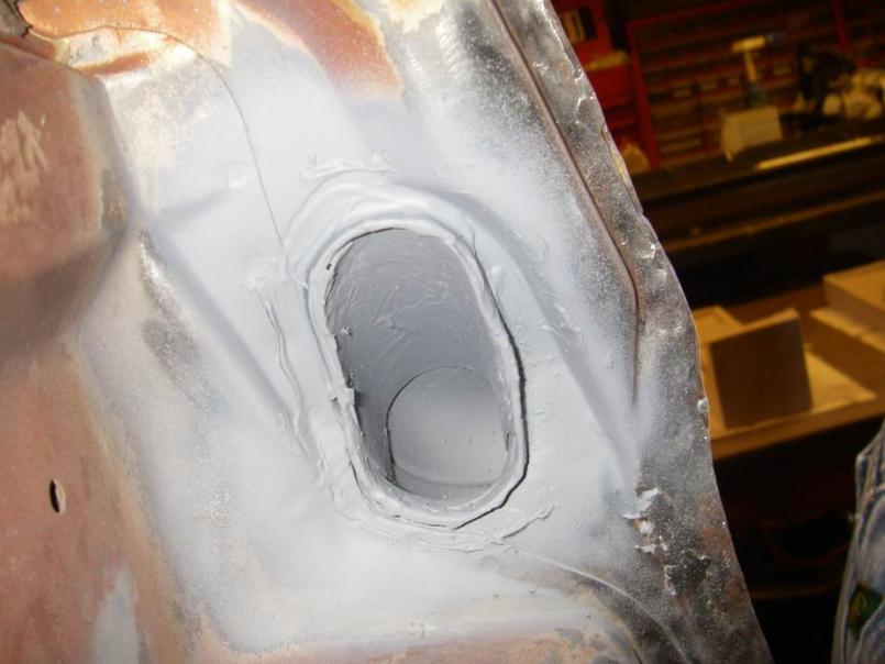
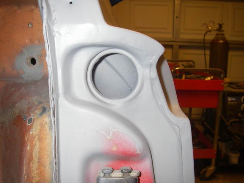
Posted by: Jeff Hail Jun 28 2011, 08:32 PM
Lets play "Guess that part" again.
Attached thumbnail(s)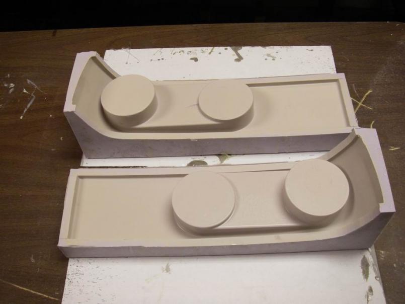
Posted by: Jeff Hail Jun 28 2011, 08:33 PM
Hint !
Attached thumbnail(s)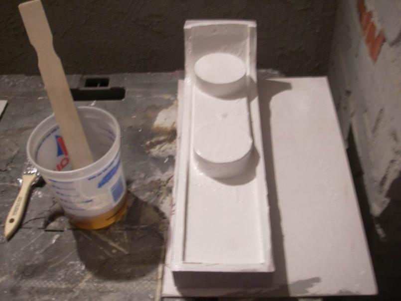
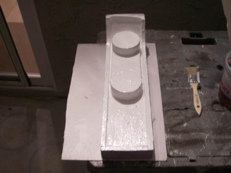
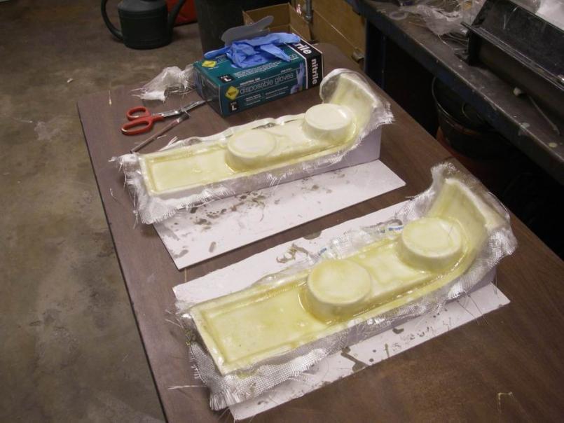
Posted by: Jeff Hail Jun 28 2011, 08:35 PM
No winners today.
Attached thumbnail(s)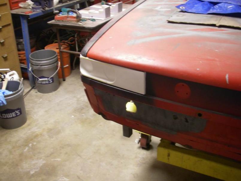
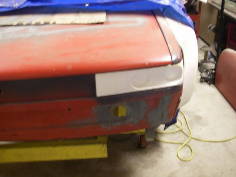
Posted by: Jeff Hail Jun 28 2011, 08:36 PM
Spare me the the mass PM's please.
These were a test run only for now.
I will let you know when they are ready.
Posted by: Loser_Cruiser Jun 28 2011, 10:57 PM
I already emailed you the other day, haha. I was hoping you were the jeff he was refering too. Always great work.
Posted by: Jeff Hail Sep 17 2011, 11:34 PM
Sometimes life goes so fast.
Attached image(s)


Posted by: sixnotfour Sep 18 2011, 12:12 AM
You know the movie quote "Italian trash"
Nice Ferrari.
Attached image(s)
Posted by: NS914 Jan 6 2012, 01:58 PM
You know the movie quote "Italian trash"
Nice Ferrari.
Aside from the Ferrari....which is sweet, how are you coming along with the 914. I just got back to this thread and my own car as well. Fantastic work and truly helpful is an understatement. Thanks so much for leading us through this.
Quick Q? Do you have more details on your shifter set up. I likely need to go back in the thread and see if i missed it.
Once again, thanks so much for what has to be one of the most informative threads in a very long time. Grant
Posted by: Jeff Hail Jan 6 2012, 10:54 PM
You know the movie quote "Italian trash"
Nice Ferrari.
Aside from the Ferrari....which is sweet, how are you coming along with the 914. I just got back to this thread and my own car as well. Fantastic work and truly helpful is an understatement. Thanks so much for leading us through this.
Quick Q? Do you have more details on your shifter set up. I likely need to go back in the thread and see if i missed it.
Once again, thanks so much for what has to be one of the most informative threads in a very long time. Grant
I'm still here just have not done any work on the 14 lately. Lot of stuff going on in life right now so the car is on the back burner. My shoulder is out and has been since May which really sucks.
Posted by: NS914 Jan 9 2012, 10:17 AM
You know the movie quote "Italian trash"
Nice Ferrari.
Aside from the Ferrari....which is sweet, how are you coming along with the 914. I just got back to this thread and my own car as well. Fantastic work and truly helpful is an understatement. Thanks so much for leading us through this.
Quick Q? Do you have more details on your shifter set up. I likely need to go back in the thread and see if i missed it.
Once again, thanks so much for what has to be one of the most informative threads in a very long time. Grant
I'm still here just have not done any work on the 14 lately. Lot of stuff going on in life right now so the car is on the back burner. My shoulder is out and has been since May which really sucks.
No worries and take care of your shoulder. I busted mine up playing hockey and that rotator cuff can be a real pain when it does not work like it should.
Like the others, I have really learned alot through your work....sometimes as much abouty what I should tackle and what I should have a "Pro" do for me. Talk soon and hope you are back at it. Grant
Posted by: Eric_Shea Nov 28 2012, 11:51 PM
Time to get busy again!
Posted by: Jeff Hail Nov 29 2012, 11:45 AM
Time to get busy again!
Yeah I know you miss me Eric. Actually I have been very busy; past year my shoulder/ rotator has been a mess. Doctors orders… absolutely no panel beating! In May I had a flood in my house which forced me to move out while remediation and repairs were made. All I have left to do is finish the custom hardwood baseboards at this point. Not a square inch of this house was spared and left untouched... except the garage. August my Mom passed away after an eight year endurance race of her life with cancer. On October 31 of all the days on the calendar I was diagnosed with Lyme. No Kings English my friend just busy with the things that happen in life. I’ve never given up on anything, not in my nature. Just had to modify the organization chart by priority. Thanks for the bump.
Posted by: Eric_Shea Nov 29 2012, 06:51 PM
Sorry to hear buddy. Get well!
Posted by: d914 Nov 29 2012, 07:46 PM
get well and start showing us all up again!!
Posted by: Trekkor Nov 29 2012, 07:54 PM
I look forward to seeing more.
KT
Posted by: mr914 Nov 30 2012, 03:00 PM
Sweet
First time I've seen your thread,spent the better part of 6 hours reading your posts.
We all look up to you for the great work you are doing and sharing with us 
Just wish I had seen this thread years earlier or... Before I started my own journey
I was in California, el segundo specifically on the last Friday of the month to visit the driving museum and discovered that hot rod magazines workshop was right next door and having an end of summer bash that evening...
Went back and saw this among the other really cool cars.
Just a thought for lights and a question, are they really legal in California. Hella Catz lights
Posted by: Jeff Hail Nov 30 2012, 03:34 PM
Hella Catz legal to the letter of the VC as a headlamp? No. Still have to have operational lows and highs to be on the right side of the grey area. I dont suppose there are actual 914 pop up lamps under those Catz somewhere?
Posted by: Rand Nov 30 2012, 03:45 PM
I volunteer as your substitute shoulder.
Posted by: doug_b_928 Feb 6 2013, 12:22 AM
Wow!!! I just read through this whole thread. Thanks so much for documenting your repairs in such detail. I'll have to re-read sections several more times, but what a terrific resource. I hope you are back to 100% soon and looking forward to seeing your finished product.
Posted by: Jeff Hail Sep 7 2013, 12:54 AM
I guess I should get something done...
24mm Carrera rotors on Carrera hubs, stubs and axels. Oh wait I did that a long time ago.
I think I will add a 911 parking brake while I'm in there since I have all these parts just laying around in boxes. Might as well also throw on the appropriate 4 piston calipers.
I have seen a lot of conversions and thought I would have to use SC rotors. Nothing of the sort. I had to trim the stainless posts on the calipers 2mm each. and the inboard brake puck backer to clear the adaptor by a hair. Other than that direct bolt on, no extra washers or extra shims. Perfect.
Attached image(s)
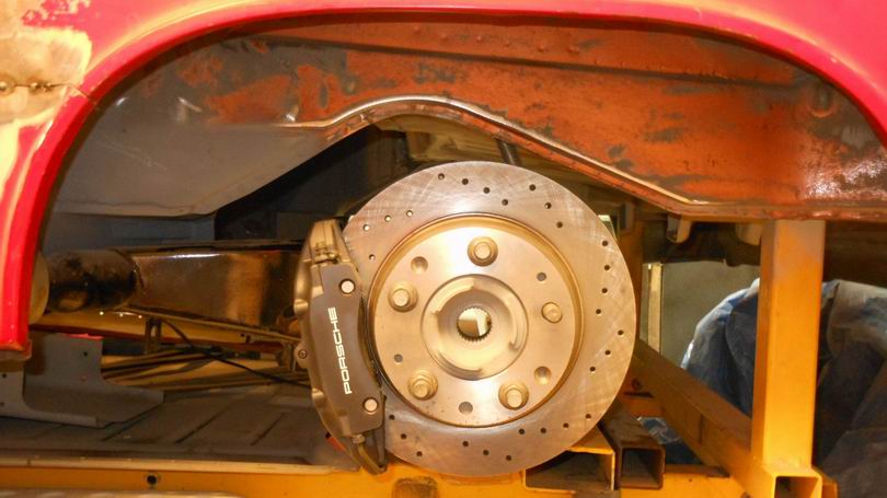
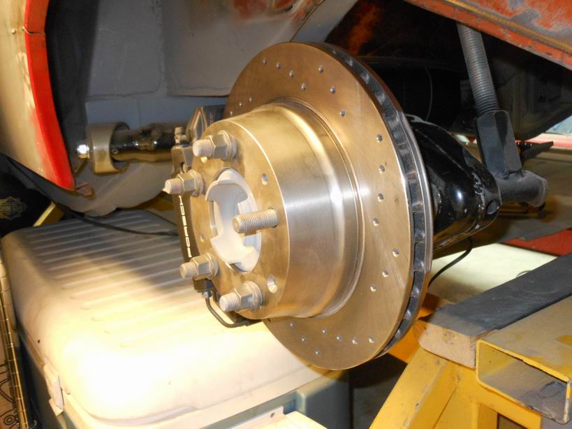
Posted by: Jeff Hail Sep 7 2013, 12:59 AM
I believe the carpets should always match the drapes.
Can't do the rear without the proper Fung Shui on the front end.
Attached image(s)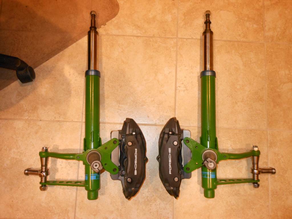
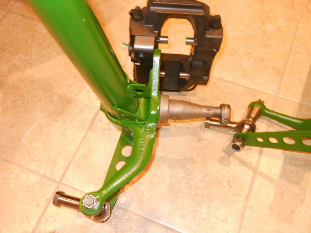
Posted by: Jeff Hail Sep 7 2013, 01:13 AM
Long way to go and a short time to get there...
Little change in the formula. The replacement ass is going to make J-Lo look like a stick figure.
Night for now
Posted by: bulitt Sep 8 2013, 01:17 PM
Great thread! Six years to write it, 4 hrs to read it ... 
Posted by: ben*james Sep 8 2013, 04:14 PM
Posted by: Vysoc Sep 8 2013, 07:10 PM
Joda is back and working on his craft, time to get back in the game again.
Jeff, Thank you for all of your excellent work, photo's, descriptions, advice, instructions!!!
I would have never tried to go after my 914-6 project if it was not for this thread, it has given me the courage to repair the Floor Pan and some rust in my long. And a bunch of other crap.
You have given so many of us the motivation to go after our challenges by taking on a bigger challenge and teaching all of us during your journey.
Thank you, Thank you, Thank you!!!
Vysoc 
Posted by: 2mAn Jan 31 2014, 02:47 PM
I hate when I get through amazing threads and the car isnt done when I finally get to the end. however, this is a thread that is more of a reference for when someone decides to tackle rust repair on ANY car. truly a work of art. Id love to watch you work, Im not too far away.
Posted by: Jeff Hail Jan 31 2014, 09:45 PM
Still here and I have never given up. I don't know how to give up! Just side tracked with other things.
To be continued...
Posted by: rsrguy3 Mar 1 2014, 02:58 PM
Any closer to some closure?
Posted by: Jeff Hail Mar 9 2014, 11:55 PM
Back to work....
Rear parking brake conversion finished. Disassemble everything and parts
moved to the powdercoater bin. Afterthought... I already powdercoated the arms once before. Oh well.
Attached image(s)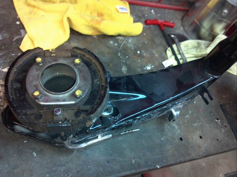
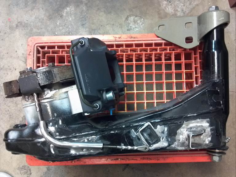
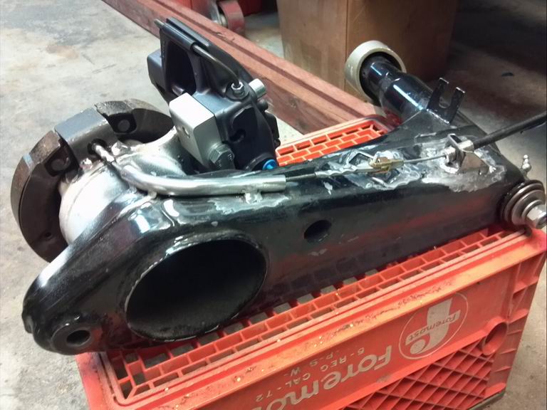
Posted by: rsrguy3 Mar 10 2014, 12:00 PM
That's pretty sweet but is it a pia?
Posted by: r_towle Mar 10 2014, 03:34 PM
nice job Jeff....
I would love to see a separate breakdown on those rear end bits and pieces....great ideas on there.
Rich
Posted by: Jeff Hail Mar 10 2014, 11:04 PM
nice job Jeff....
I would love to see a separate breakdown on those rear end bits and pieces....great ideas on there.
Rich
Rich -
You caught me after I took everything apart and put it away until I can take a bunch of parts to the powdercoater in one batch!
Basically the arms are boxed. Have Foleys pivot bracket and parking brake kit. For what Chris's kit cost it wasn't worth going buying a quality swaging tool, cable, fittings etc. to use it one time and his CFR stuff works. Elephant bushings. The wheel bearings are stock 914 Fag on Carrera hubs with a spacer to use the Carrera axels. The parking brakes I bought used from a 912 for $15 off the Samba. Only thing that was good are the pads, adjusters and backing plates. I bought all new hardware (springs, retainers, spreaders new). The calipers are obviously Boxster which these days make no sense to buy used since the price has dropped dramatically. The adapters came from Rich Johnson.
DID I SAY "Have Foleys pivot bracket and parking brake kit. For what Chris's kit cost it wasn't worth going buying a quality swaging tool, cable, fittings etc. to use it one time and his CFR stuff works".
Chris/ CFR always gets a plug from me.
This is all the small consumable parts I ended up buying. The arm modification is straight forward. Grind the bearing carrier down until the backing plate fits like a hat. Weld the pad stop on, CFR cable tube and relocate the cable anchor bracket.
Attached image(s)
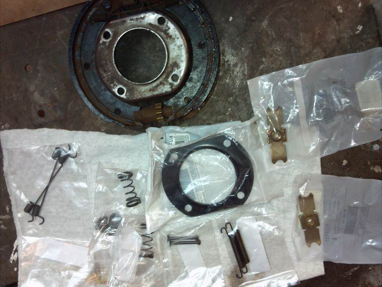
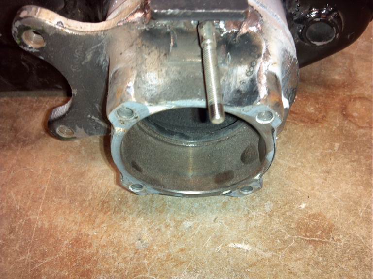
Posted by: Jeff Hail Mar 10 2014, 11:05 PM
That's pretty sweet but is it a pia?
Not at all. Its fun! Considering everything except the caliper adapters and CFR cable kit are off the shelf P-Car parts its really simple.
Posted by: Jeff Hail Mar 10 2014, 11:15 PM
God gave to Nascar and he also taketh away from the Nasty Car guys and then put it my garage.
I picked up a used 4 gallon Patterson oil tank ridiculously cheap. Half a dead president cheap. 16 AN fittings, dual outlets, dual breathers and triple inlets. Came with a tank heater, two temp probes and a couple of monsterous mounting straps. A little wear but clean and no leaks.
Patterson is located close by at the Van Nuys airport so I only need to pickup a new o-ring. I may have them shorten the inlets and close one off.
Attached image(s)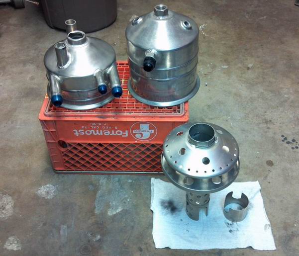
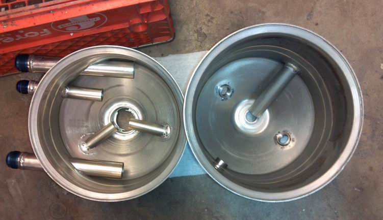
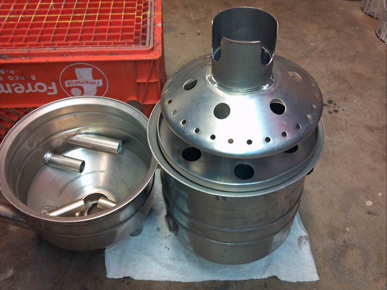
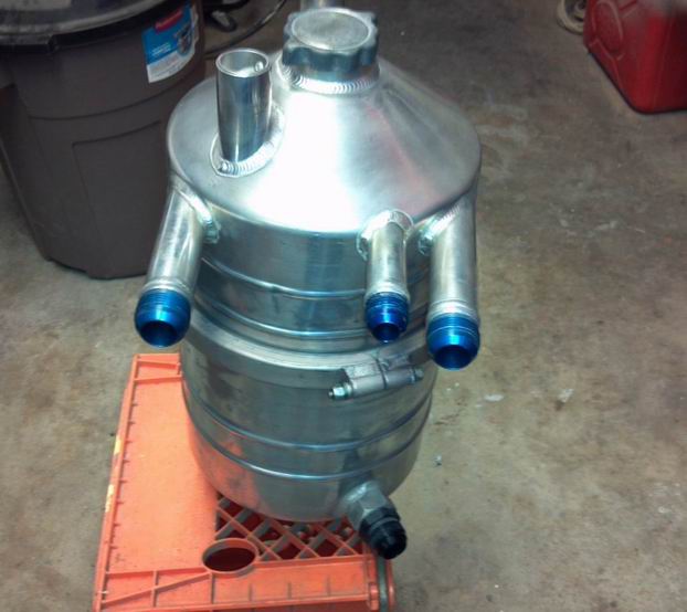
Posted by: rick 918-S Mar 11 2014, 07:15 AM
I haven't clicked on this one lately. Very nice!
Posted by: Eric_Shea Mar 11 2014, 08:51 PM
What the hell did I miss here? Jeff turned a pressure cooker into an oil tank?
Posted by: Jeff Hail Mar 16 2014, 08:56 PM
43 Plymouth dash? Nope!
Attached image(s)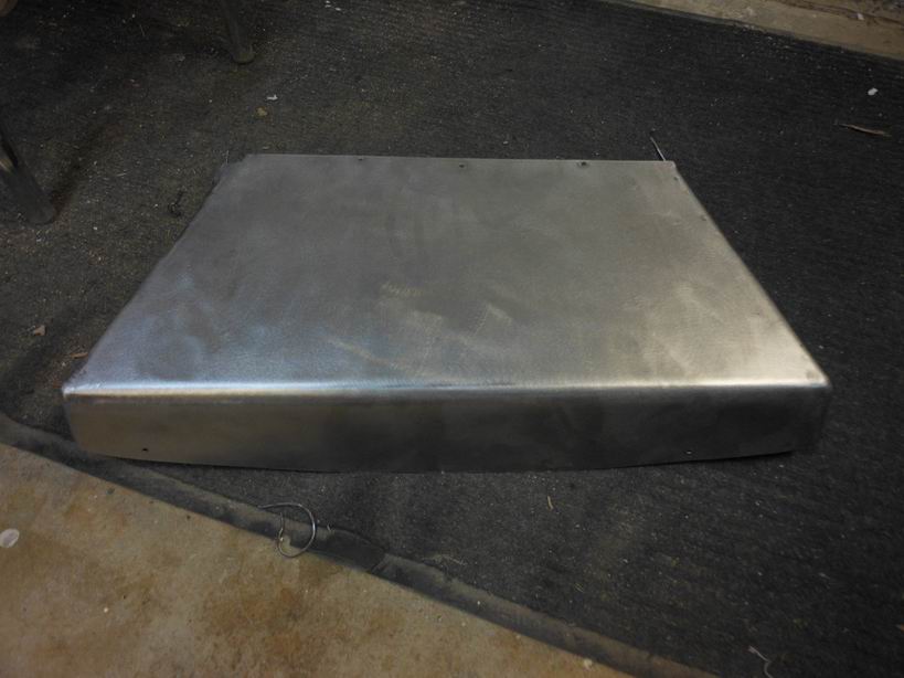
Posted by: Jeff Hail Mar 16 2014, 08:58 PM
Got to make some room.
Thought about putting a Carrera front spoiler oil cooler but those things are really long at 21+ inches. Would not follow the body contour and would interfere with the bumper fit.
Standard Carrera fender oil cooler tipped on its side. They flow that way anyways.
The core is 13 x 7 x 2.5 which provides a lot of heat throw.
I will shroud the bottom of the cooler and leave an exit behind and under it since it has plenty of room on the backside of the cooler. Its 2 inches above the bottom of the floor well so it wont bottom on anything.
More welding and grinding to finish it off but you get the idea.
Never liked the idea of weather or oil cooler exhaust air going into the trunk.
Attached image(s)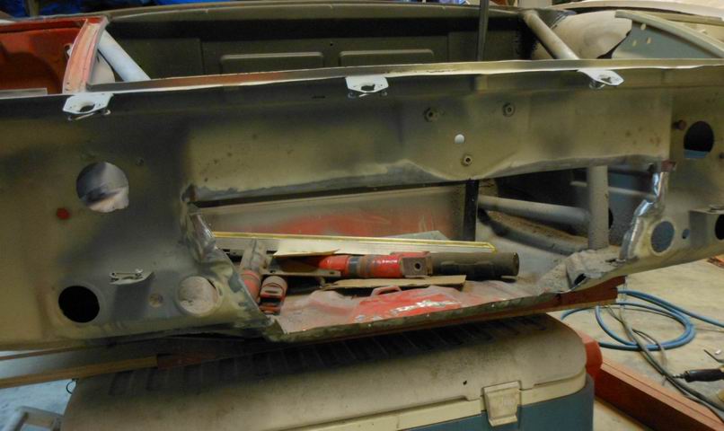
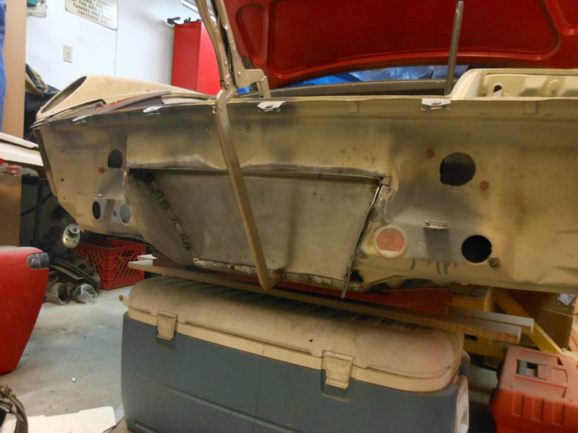

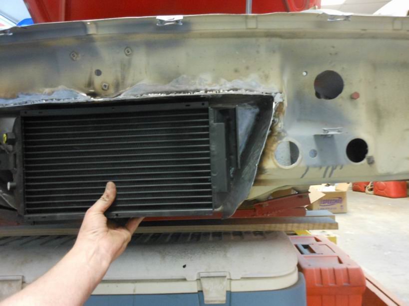
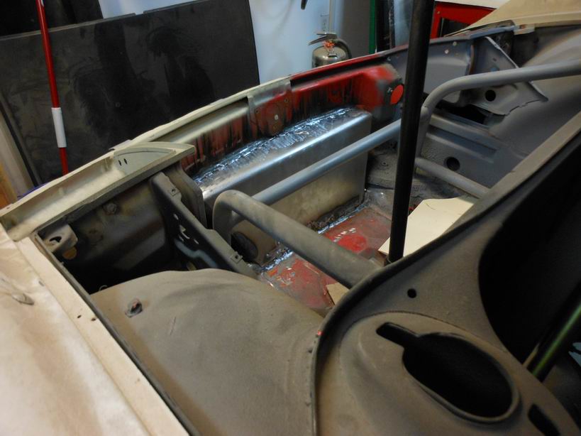
Posted by: Jeff Hail Mar 16 2014, 09:43 PM
The metal I used is 16 gauge. Would like to have a little bit of strength considering what was removed. Its tied into the floor where it rolls upward and across to each control arm reinforcement to just below the latch.
Funny I used to be able to grab the nose just above the hood latch and it would flex a little. Not anymore. That area is plenty stout now,
Attached image(s)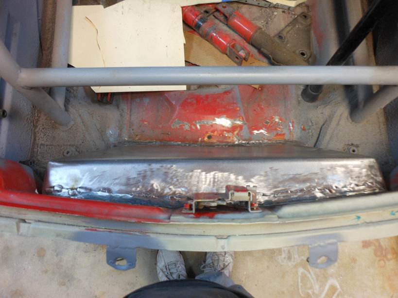
Posted by: Jeff Hail Mar 20 2014, 11:29 PM
Hey its got a front end again. A little "R" styling for the oil cooler inlets. Will need to modify the spoiler ends to fit the flairs better later.
Attached image(s)
Posted by: Jeff Hail Mar 20 2014, 11:35 PM
It has a rear end to ! Lots of work to do here.
Attached thumbnail(s)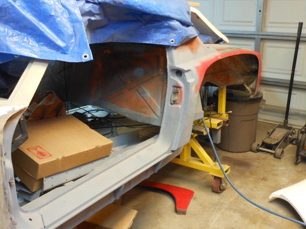
Attached image(s)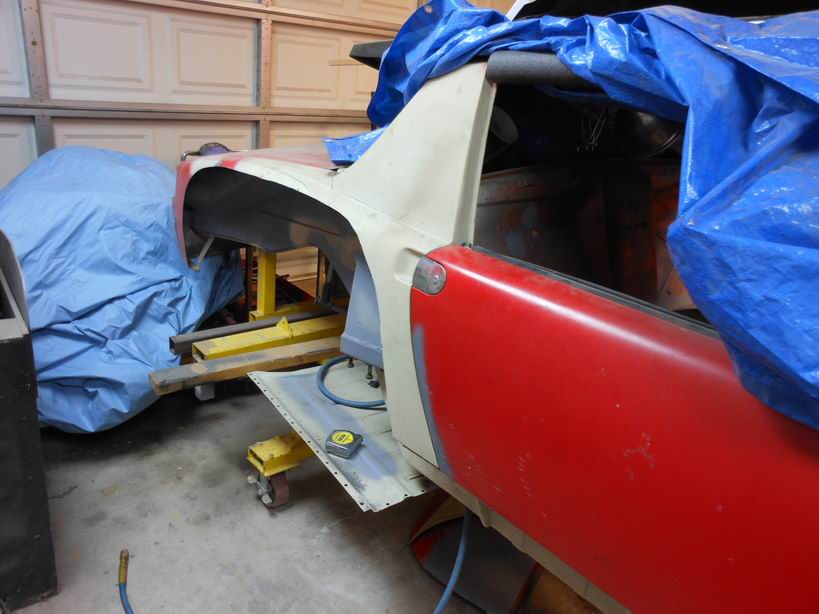
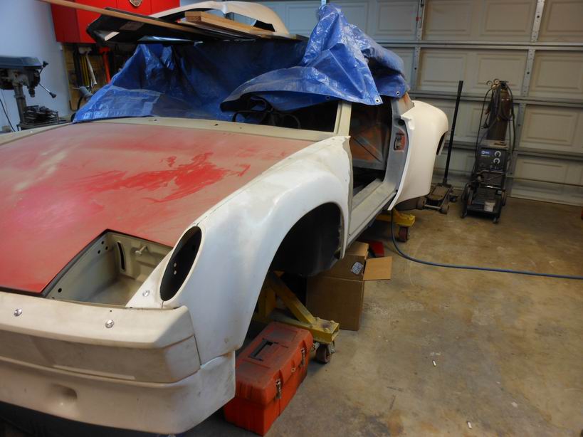
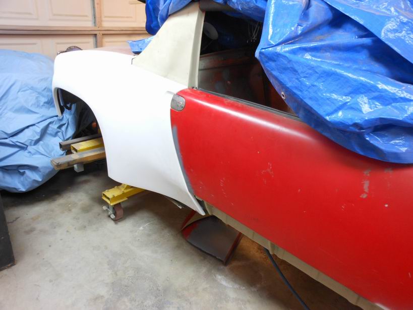
Posted by: Jeff Hail Mar 23 2014, 12:41 AM
Rear lighting. Bases painted and assembled.
Attached thumbnail(s)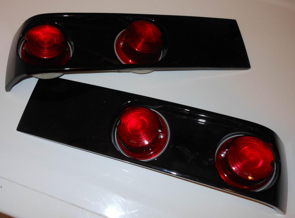
Posted by: jaxdream Apr 3 2014, 05:45 PM
Tip your bartenders and waitresses...
Word has it around here you are a class act
Are you tending bar tonight or the host?To back up a bit to last weeks intimate conversation. Here are the spacers for using the late Carrera hubs (one inner, one outer on each side of the 914 wheel bearing). Easy enough? Rotors are also Carrera. Depending on going 20mm or 24 mm appropriate caliper half spacers required.
By the way you spelled Carrera incorrectly. Two "R's always come before the single "R". I just wanted to point that out you know. I am sure the bartender or host will volley back with a good jab just for fun. Thats getting back for the Kings Lad thing.
Jeff please explain the second spacer that appears to go on the backside of the bearing/ SC hub ?? I got and installed the 5mm spacer that goes on the front side / wheel side of the hub to use up against the bearing to use the wider bearing SC hub . Thanks for any info on this setup.
Jack
Posted by: Jeff Hail Apr 3 2014, 10:12 PM
Tip your bartenders and waitresses...
Word has it around here you are a class act
Are you tending bar tonight or the host?To back up a bit to last weeks intimate conversation. Here are the spacers for using the late Carrera hubs (one inner, one outer on each side of the 914 wheel bearing). Easy enough? Rotors are also Carrera. Depending on going 20mm or 24 mm appropriate caliper half spacers required.
By the way you spelled Carrera incorrectly. Two "R's always come before the single "R". I just wanted to point that out you know. I am sure the bartender or host will volley back with a good jab just for fun. Thats getting back for the Kings Lad thing.
Jeff please explain the second spacer that appears to go on the backside of the bearing/ SC hub ?? I got and installed the 5mm spacer that goes on the front side / wheel side of the hub to use up against the bearing to use the wider bearing SC hub . Thanks for any info on this setup.
Jack
Easiest way to explain: Using Carrera hubs and axels. The late 911 stuff uses a wider bearing. To use the 914 cartridge bearing the spacers simply make up the difference in width on each side to match the 911 bearing. The spacers are sized accordingly to properly space the hub in the trailing arm. Boils down to making the bearing cones wider while retaining the dimension of the 914 bearing at the race so as to not modify the 914 trailing arm at the bearing carrier. If you are going with Carrera axels you will need both spacers.
The rotors are a matter of choice and really depend on the calipers being used. I just swapped a buddy my Carrera rotors for SC rotors because Shea will bust my balls about the weight difference. Maybe he wont because he is so cool. When I decided to go with Boxster calipers can use either rotor.
I just went through some parts and have everything out. Let me see if I can take some photos to show the differences. Will add shortly.
Posted by: Jeff Hail Apr 3 2014, 11:01 PM
Carrera axel and lug centric hub on the left with spacers installed.
914 bearing
914 axel on the right.
As you can see the axel stub shank is the same length for both the 911 and the 914.
The shank is the same diameter on both. The splines are different (one course, one fine).
The Carrera axel stub has a more defined step on the shank where the bearing butts up against it. The spacers are chamfered to accommodate this.
With the bearing and hub installed the offset would be incorrect. The spacers correct that issue to center the hub face so the rotors center with the caliper mouth.
Attached thumbnail(s)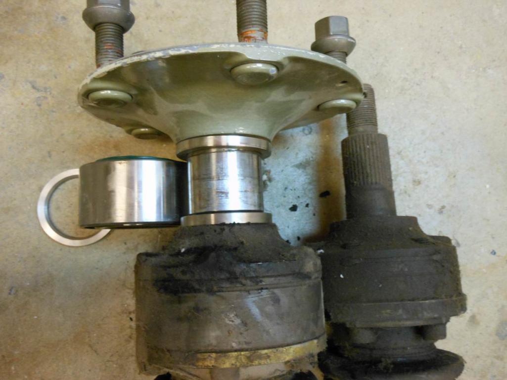
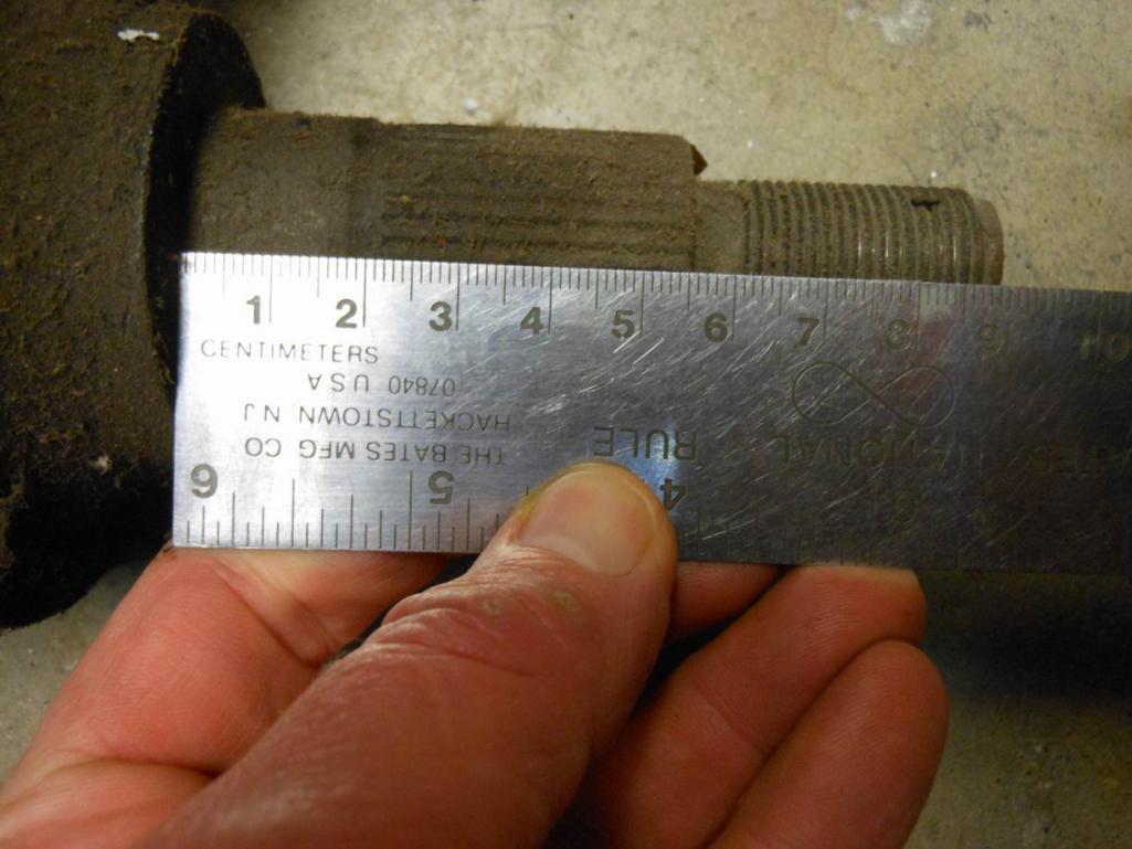
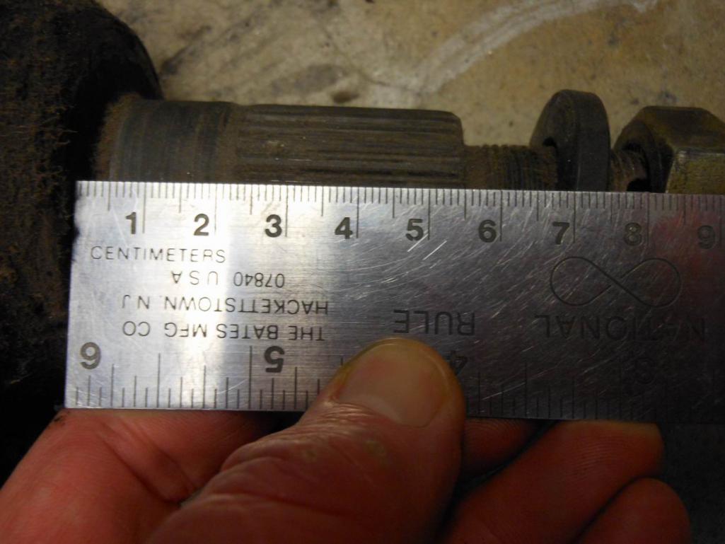
Posted by: jaxdream Apr 4 2014, 07:49 AM
Ok I gottcha , you are centering the Carrera hub in the bearing and using Carrera axles also. It seems a matter of getting the right parts with spacers to work around the 914 bearing size . Nice that these are available to source for differing setups. Thanks again for the info, somthing to ponder.
Jack
Posted by: Jeff Hail Apr 13 2014, 02:21 PM
Unhappy with factory lighting and unsatisfied with the bulb output of the Hella R tailites had to take this to another level.
Sourced some dual output (running, brake) LED clusters. They were the brightest I could locate using red LEDS. Red LEDS with red lenses were the obvious solution since white LED washes the color.
Attached image(s)
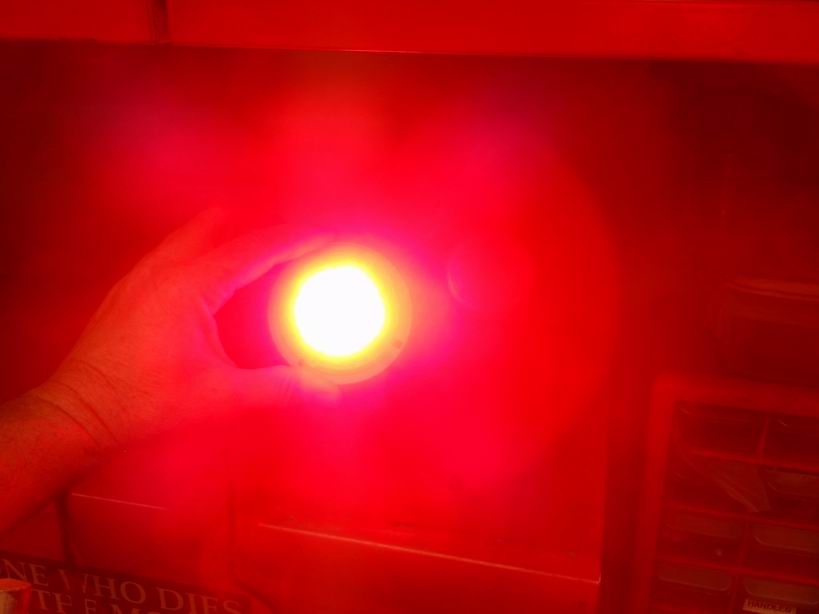
Posted by: Jeff Hail Apr 13 2014, 02:25 PM
Modified the Hella bulb housings and installed some standoffs to bring the cluster close to the lens. Because there is no side marker I needed the cluster to illuminate the lens from all angles.
The clusters are waterproof since they are dipped in epoxy. I let these run for 1 hour straight and they do not get hot at all. In fact they don't even get warm.
Attached image(s)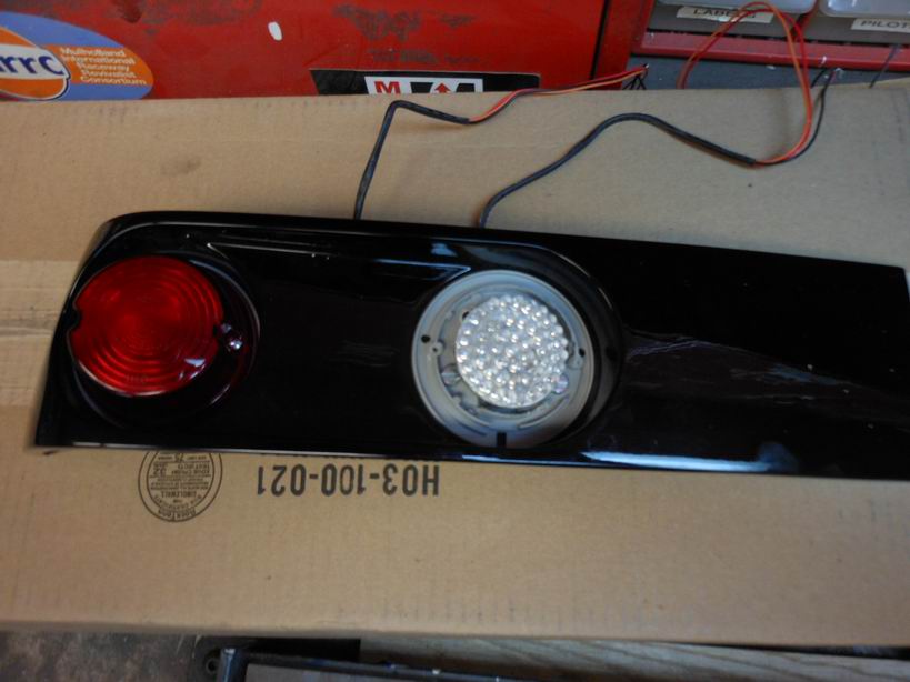
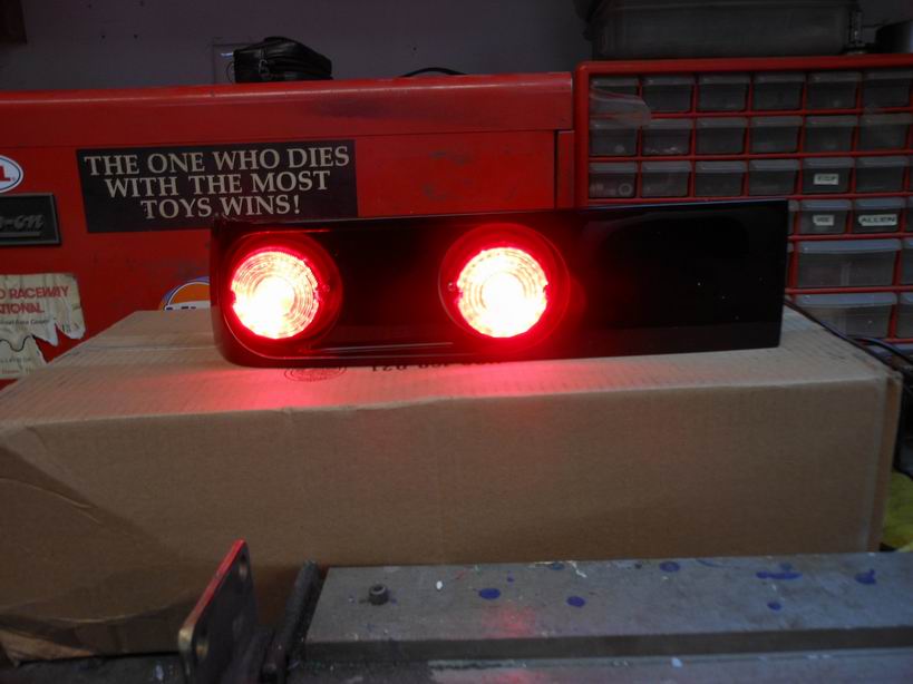
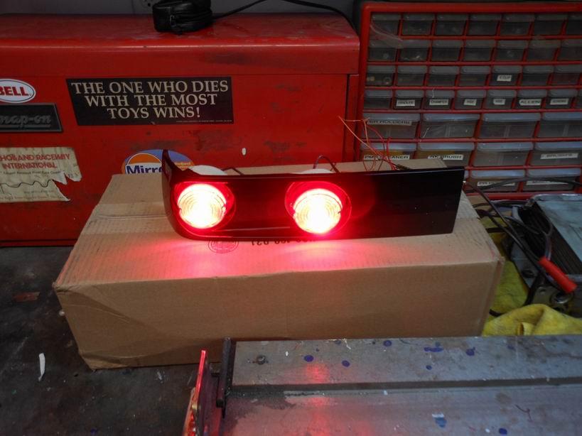
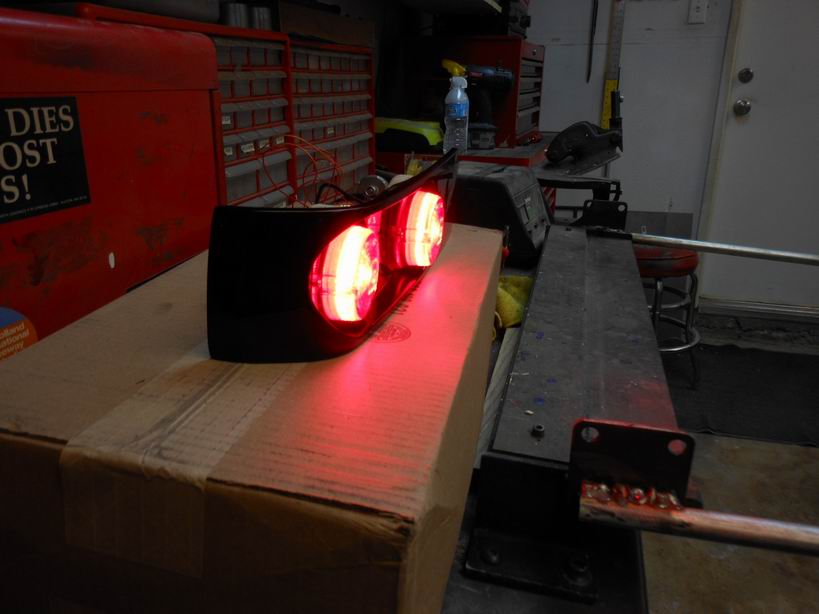
Posted by: Jeff Hail Apr 13 2014, 02:30 PM
With the lights in the garage out these are really bright on both the run and stop modes.
The last photo is of the ceiling to show how much output these give off. Lit up the whole garage. This was a test with a single lamp on.
Very bright and I am satisfied.
Attached image(s)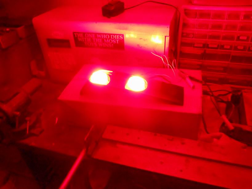
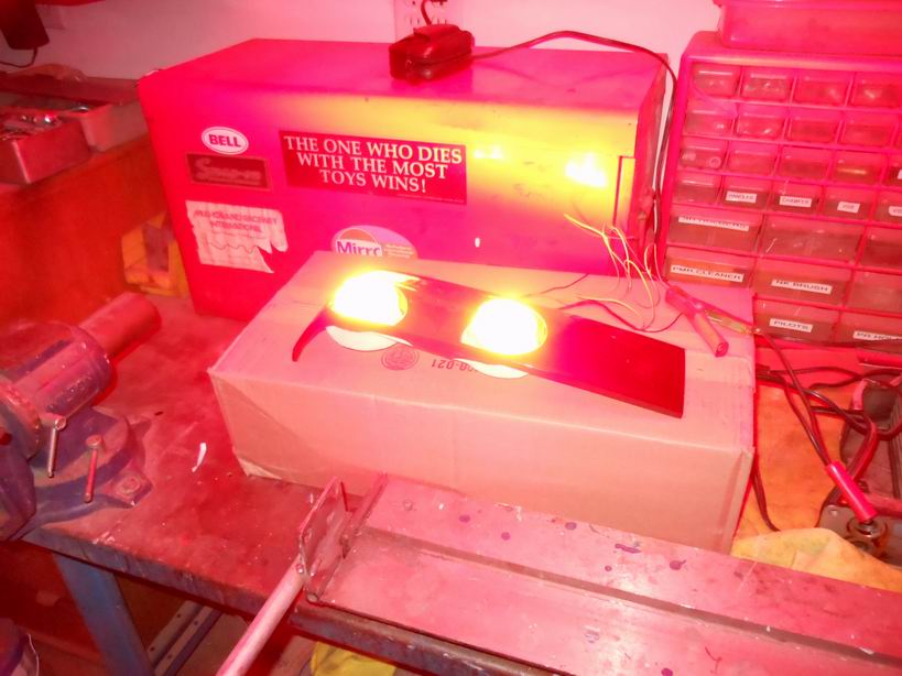

Posted by: Eric_Shea Apr 13 2014, 06:14 PM
Nice work Jeff. Nice to see some skin on it!
(you can install as many flywheels on your car as ye see fit. I'm just an innocent bystander)
Posted by: Maltese Falcon Apr 13 2014, 06:18 PM
Jeff, I'll need to source some of the hub-to-bearing spacers soon.
Are you still parking the chop top 911 in your front rec-room?
Marty
Posted by: Maltese Falcon May 15 2014, 11:31 PM
Jeff...any updates on your build ?
Hope your shoulder+ hand are doing better...I joined the sheet metal lacerated finger brigade as well
Marty
Posted by: 76-914 May 16 2014, 09:02 AM
Rear lighting. Bases painted and assembled.
Jeff, I've seen this style tail light assm in 2 other builds. Are they available aftermarket? Looks good!
Posted by: Jeff Hail May 16 2014, 11:52 PM
Jeff...any updates on your build ?
Hope your shoulder+ hand are doing better...I joined the sheet metal lacerated finger brigade as well
Marty
Been working on the 14 just have not been taking photos.
Posted by: Jeff Hail May 16 2014, 11:57 PM
Rear lighting. Bases painted and assembled.
Jeff, I've seen this style tail light assm in 2 other builds. Are they available aftermarket? Looks good!
Honestly they are a pain in the ass to make. No aftermarket because I own the molds and masters.
Attached thumbnail(s)
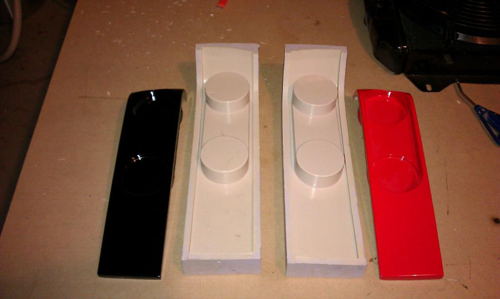
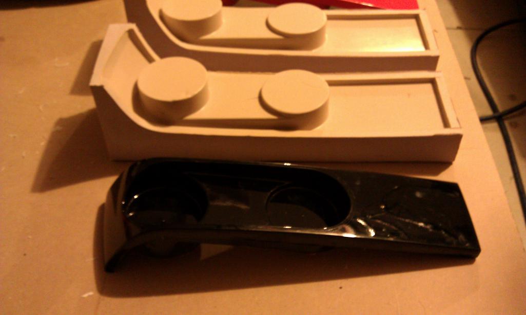
Posted by: Jeff Hail Oct 31 2014, 12:26 AM
I'm working
Attached thumbnail(s)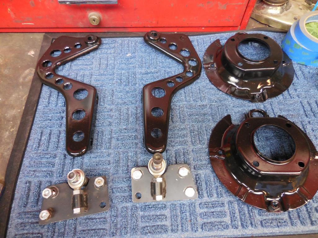
Posted by: Jeff Hail Oct 31 2014, 12:26 AM
I'm working
Attached thumbnail(s)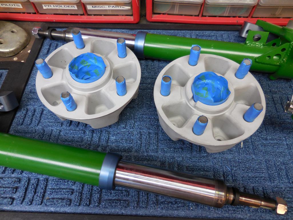
Posted by: Jeff Hail Oct 31 2014, 12:28 AM
I'm working
Attached thumbnail(s)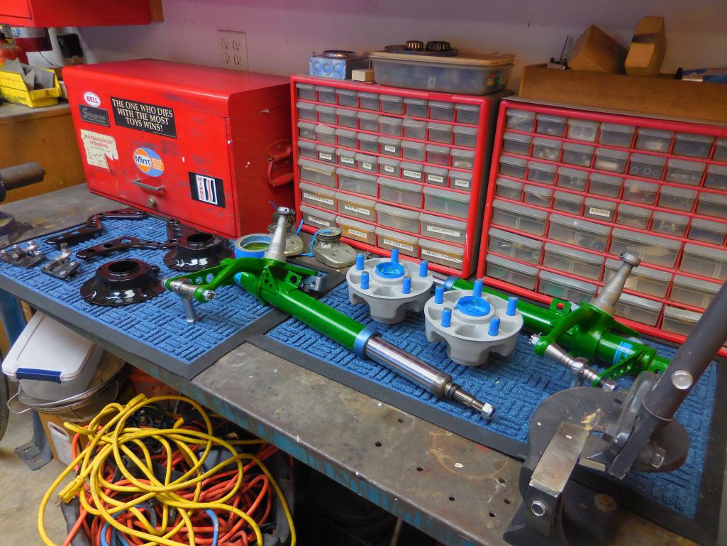
Posted by: Jeff Hail Oct 31 2014, 12:33 AM
Really like my NEW blasting cabinet. Inexpensive, doesn't take up a ton of space like commercial units BUT will do everything a commercial unit does. MADE IN TEXAS/ USA and a well thought out design. Will handle larger size parts. So far I have used both glass beads and StarBlast media.
It doesn't leak like the HF POS!
A Plug for the Barrel Blaster
http://www.barrelblaster.com/
Attached thumbnail(s)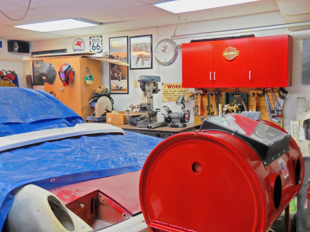
Posted by: Jeff Hail Oct 31 2014, 12:41 AM
Added more lighting to the shop.
Quote: Eddie Murphy - "I can see, I can see! "
Attached thumbnail(s)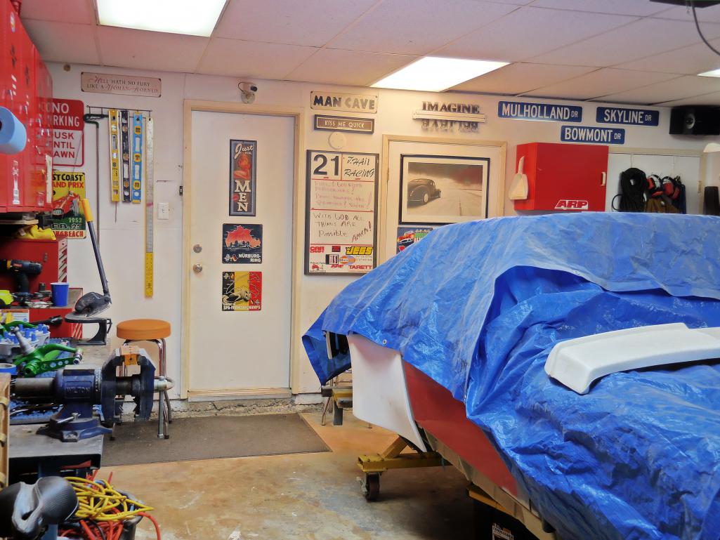
Posted by: injunmort Oct 31 2014, 04:34 PM
I have a first generation barrel blaster and been upgrading it for last 13 years. great blaster, great price and great manufacturer support. works better now than it did when I bought it. they are a great tool.
Posted by: Jeff Hail Oct 31 2014, 09:58 PM
Funny that you ask what happened to Toppers parts.
A spoiler I picked up I had to enlarge the opening, center it (inlet opening was off on one side by 2 inches) and generally reshape it so its uniform.
Now the lower inlet and upper round holes are very close to the Carrera cooler size in sq inches.
The white gelcoat spoiler photo is before I made changes to it.
Attached image(s)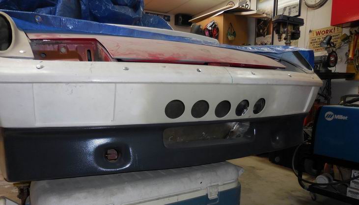
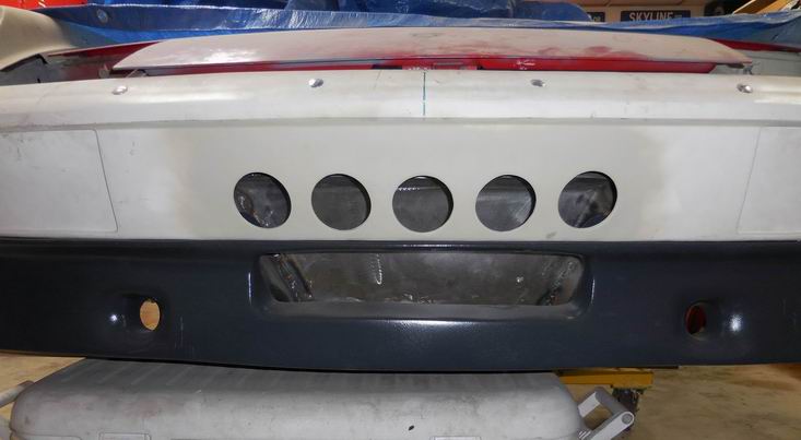
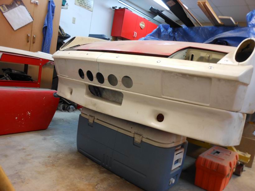
Posted by: Jeff Hail Oct 31 2014, 10:10 PM
These are the rocker moldings I picked up from Toppers estate.
Stock molding in the middle used for comparison.
Attached image(s)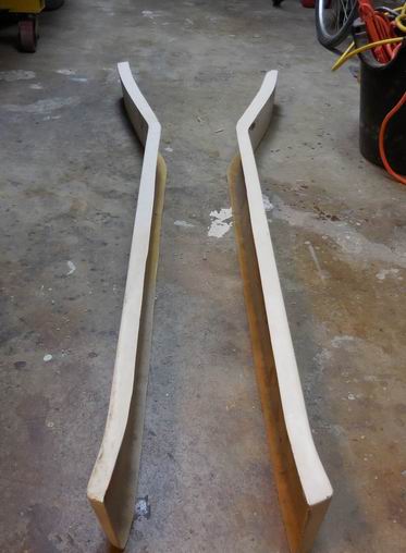
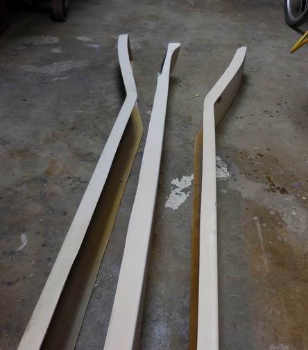
Posted by: Jeff Hail Oct 31 2014, 10:15 PM
How rude of me
Seasons Greetings and other uses for a welding jacket.
Attached image(s)
Posted by: OllieG Nov 6 2014, 03:51 AM
A really good product I have used for years is Jasco metal etch. It's a little different than metal ready. 1st its more agressive and only has to sit about 10 minutes (the instructions says 1 minute and rinse) versus some other products out there. It is very cheap in comparison to others and I think does a better job overall because it is full strength. (3/1, 2/1 with H20 or full strength as I use it right out of the bottle)
This is an excellent etching product. What it does not do ......It is not a conversion coating as it has no zinc or phosphate. If you are repairing and going directly to epoxy primer Jasco is a great product. If you are leaving metal exposed for a period you may get some flash and probably should use a zinc conversion coating even on good clean steel.
I am not fond of conversion coatings because rust is rust no matter what color it turns.
Enjoying reading this thread. I'm psyching myself up to tackle the same cowl repair you did. I reckon it's going to be the most challenging job of my resto for my newly learned and limited fabrication and welding skills!
I'm using epoxy primer like you and was wondering what the Jasco Metal Etch was for?? If you're wire-brushing the surface rust off, isn't the surface roughened enough by the brush just to take the epoxy straight, without needing to acid etch aswell?
Can you also use the Jasco to etch the first coat of epoxy so you can get additional coats to adhere?
Cheers.
Posted by: Jeff Hail Nov 6 2014, 03:58 PM
3M Metal Prep or Jasco is just phosphoric acid. Jasco is about a third the price and you get a bottle three times as big.
The acid is a good surface conditioner which aids in bite while also leaving beyond some zinc.
Wire brushing isn't enough to abrade the surface for good coating adhesion. Wire brush is good for post weld clean up.
Posted by: mrbubblehead Nov 6 2014, 08:16 PM
what about a sand blasted surface jeff? would that be a good enuff surface to epoxy primer over?
Posted by: Jeff Hail Nov 6 2014, 09:15 PM
Depends on what grit abrasive is used. I finer media tends to create a good mechanical bond. Generally the answer would be yes but a proper cross-hatch abrading is proven to be best in conjunction with a chemical bond such as Epoxy. Epoxy is sticky stuff but like any coating surface prep is key to a good finish.
Imagine blasting with 60-80 grit media then going right to priming with EP or surfacer. You would still have a zillion micro craters to "fill" to get past the texture in the surface. Sand it and shoot another coat of EP, or skim coat it with glaze, or high build primer, sand some more, etc etc. At that point the mil thickness is building quickly.
Posted by: Jeff Hail Nov 18 2014, 02:16 AM
Anyone that has ever removed bearing races from 911 hubs knows there is any easy way if you have later hubs because they have a relief cut in the bore to catch the edge of the race. A flat edged tool is pretty much all that is needed. Its still the Captain Cave Man way because you will still damage the race rendering it unusable pounding it out.
I have the last year hubs before Porsche added the relief cut.
Conundrum: (Which is a great bottle of wine I may add). I'm replacing new races and bearing so who cares if they get destroyed right? The early hubs tend to get beat up with the flat edged tool no matter. The early hubs tend to get the shoulder the races seat on beat up. One burr or high spot on the race shoulder edge you will end up with hub that wobbles radially - NO BUENO!
The other issue I have seen with about 30 bearing /race replacements is if you end up with a burr or high spot and when installing the new races they end up galling inside the hub...again causing radial issues. Once this happens out come the new races and you start over again. Hopefully you don't have to purchase a new set of bearings with match set of races again. Seen it too many times to mention.
The solution: Correct tools for the job.
On the left: Race installation driver. Off the shelf tool except I had to modify it for the correct angle for depth. Have you ever priced out the German Bearing/Race installation kit? Its running over $300 today. My driver was $8 and three minutes of lathe time.
In the middle: Two old races cut and welded so they are a little smaller in diameter than the bore. These work perfectly as lapping tools when 600 grit lapping compound is used to remove any galling and square up the bores. After thought they also double as installation adaptors to seat new races in the bores.
On the right: A tube bending wheel cut down on a lathe to use as a race removal tool to press out the outer race WITHOUT DAMAGING it. In case of seating issues due to galling I can press new races out in 10 seconds and use them again.
I have seen so many hubs trashed or called junk due to galling in the bores. No more. Easily corrected to zero run out.
Attached image(s)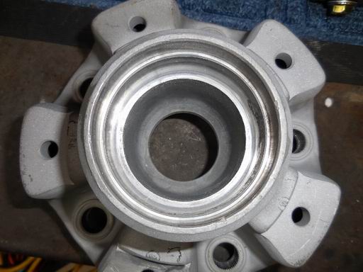
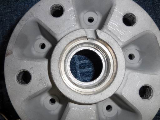
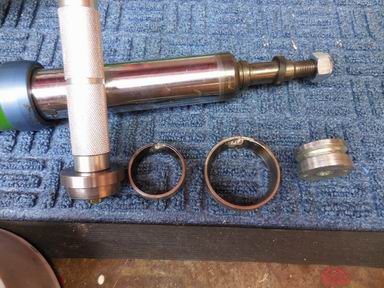
Posted by: Jeff Hail Nov 18 2014, 02:21 AM
Pressing in the new races GENTLY. I believe a press is the only and right way to do this procedure....
Attached image(s)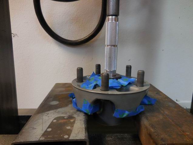
Posted by: Jeff Hail Nov 18 2014, 02:25 AM
Ready to go. Races installed. Bearings packed. Installed on the strut assembly. I also replaced the often neglected hidden O-ring behind the bearing spacer.
I glass beaded the hubs to clean them up. I also sprayed a light coat of 600 degree engine clearcoat to keep them from oxidizing. Baked at 200 and 400 with 30 minute cool down cycles in between.
I thought these were clear anodized originally. I was wrong.. some sort of clear crud was applied from the factory. It came off to easy for it to be anodizing.
Attached image(s)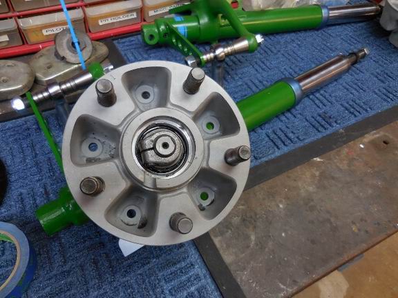
Posted by: Maltese Falcon Nov 19 2014, 01:58 PM
Jeff,
Good tip on the front hubs...definitely will have these looked at by Mr. Alarcon my suspension guru.
Keep up the xlnt painstaking work !
Marty
Posted by: Jeff Hail Nov 30 2014, 01:28 PM
The art of restoration.
The only parts that are new are the spreaders and spring retainer cones. Everything else including the shoes were glass beaded and finished. The brass star adjusters were glass beaded and then polished.
From rusty to perfect.
Attached image(s)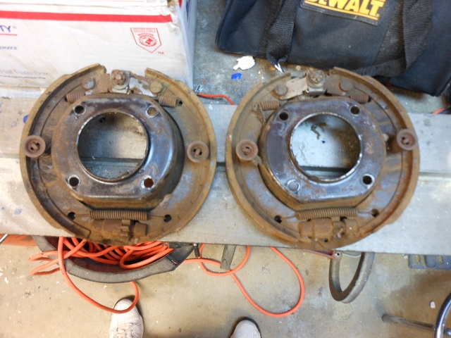
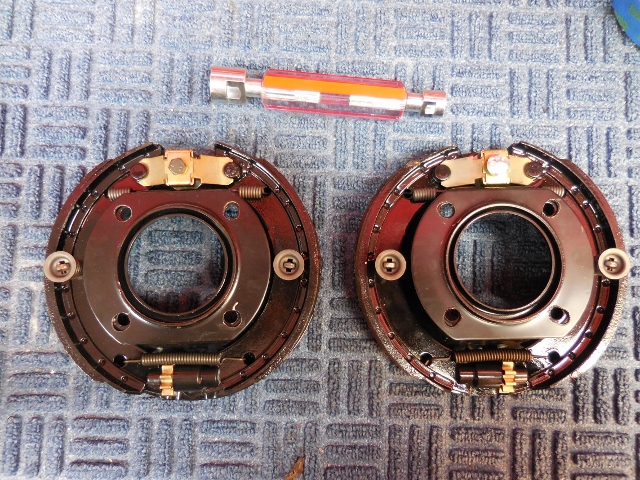
Posted by: Jeff Hail Nov 30 2014, 01:32 PM
I deviated from one thing on Foleys 911 e-brake mod. I cut the return spring in half behind the spreader (since only one spreader is used) and placed a washer where the cable passes through to provide a little extra push on the shoe retract.
Attached image(s)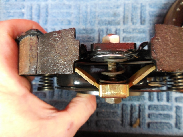
Posted by: Jeff Hail Nov 30 2014, 01:38 PM
In process
Attached image(s)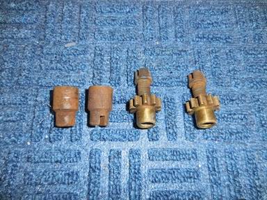
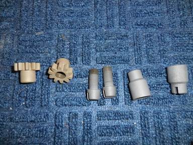
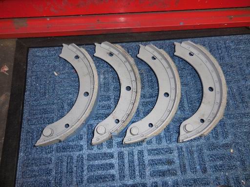
Posted by: Jeff Hail Nov 30 2014, 02:07 PM
I was called last night by my friend Victor Van Tres. (Showroom Stock Champion)
With a chuckle in his voice and a sense of urgency I was invited to drive in the 24 Hour Race of Endurance in Sonoma next weekend. Yes another 24 Hours of LeMons.
I respond with a return laugh of sarcasm what kind of Grand Touring Prototype knowing he only races Renaults and Peugeots?
Out comes its for TEAM PEUGEOT DADDY and the car is a 404. My brain starts firing and I'm thinking wow a 404 has four wheel drum brakes and maybe 60 hp this can get interesting and would be fun?
In the end I had to turn down the seat stint due to other plans.
A pic from the old team at Thunderhill. I'm still wondering how Victor obtained this fine stead?
Attached image(s)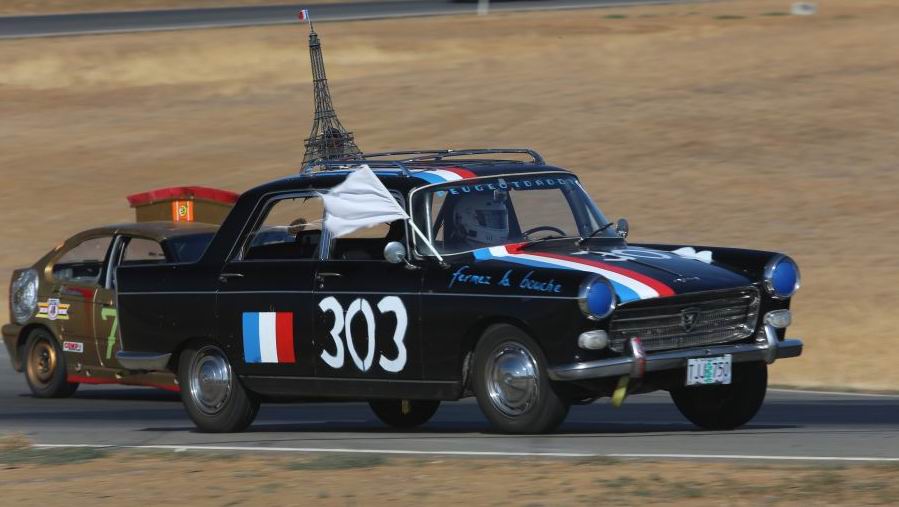
Posted by: Jeff Hail Dec 13 2014, 12:24 AM
Pre-fit the motor mount and burn it in.
Attached image(s)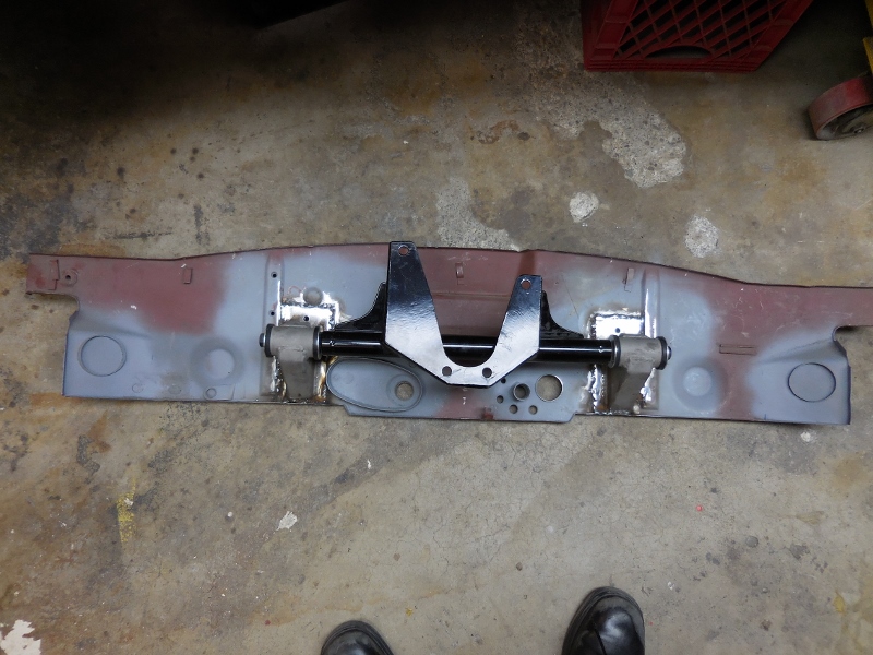
Posted by: Jeff Hail Dec 13 2014, 12:35 AM
24 Hours of LeMons/ Sonoma California
The Peugeot Daddy Team 404 actually finished the race out of shear pride. Even with an overheat condition and late hour multiple rod knocks, the Pit crew quickly went to work in the pits with pepper to quell the overheat, changed to 50 weight oil increasing film thickness extending the inevitable destruction of lower end. The tired 404 made it across the finish line after 24 hours. At the 23rd hour the lowly 404 abandoned its moniker French white flag to accomplish the impossible. The tired and weary drivers gave it there all to avoid the dreaded DNF.
Attached thumbnail(s)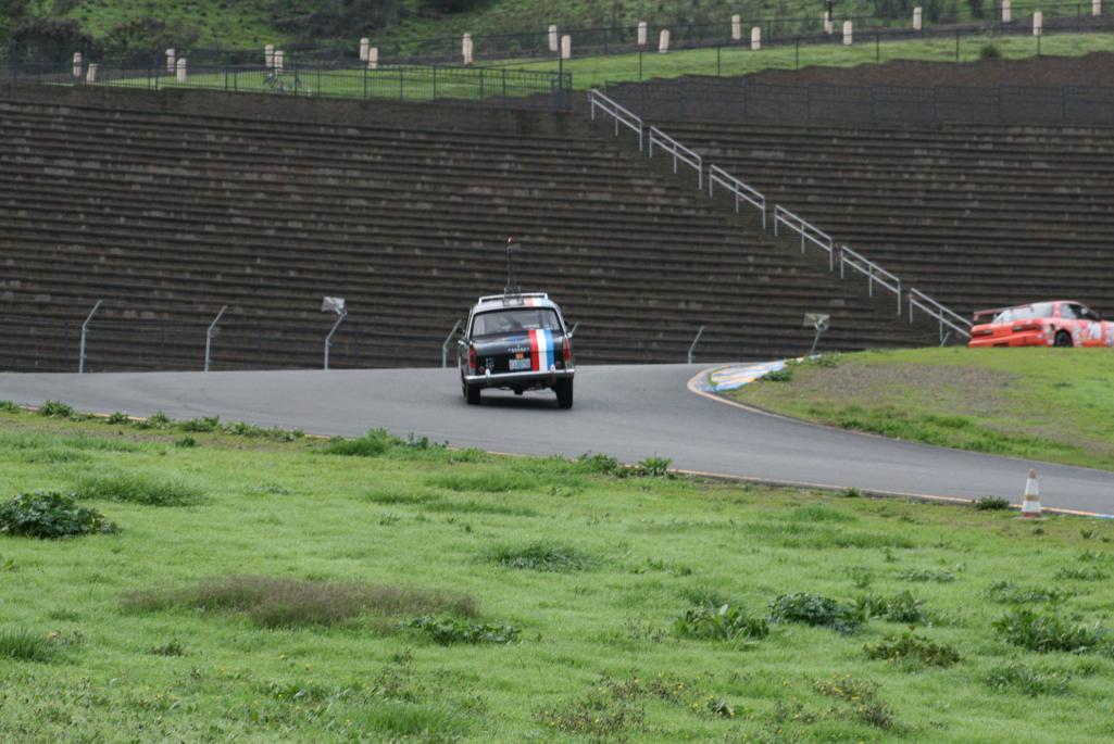
Attached image(s)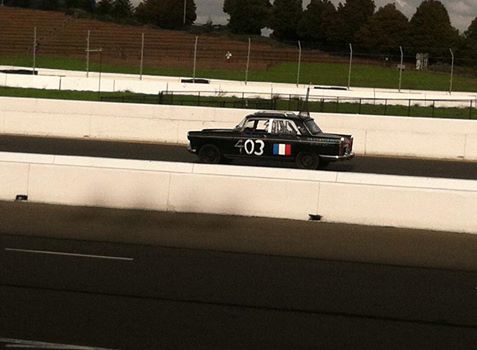
Posted by: Jeff Hail Dec 24 2014, 01:16 AM
Completion of strut #2
Installing inner bearing race
Attached image(s)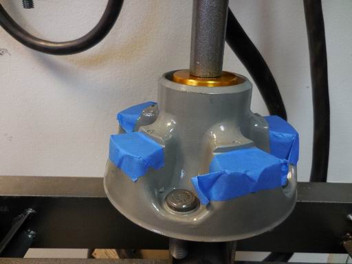
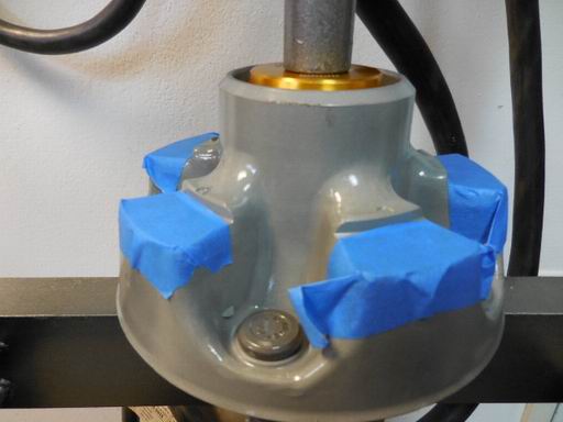
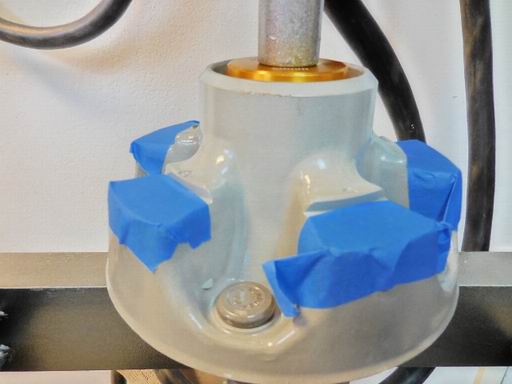
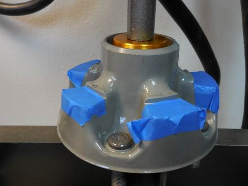
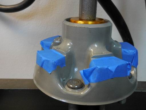
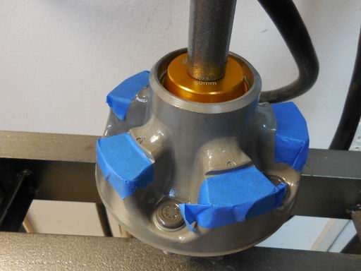
Posted by: Jeff Hail Dec 24 2014, 01:16 AM
Installing outer race and pressure packing bearings.
Attached image(s)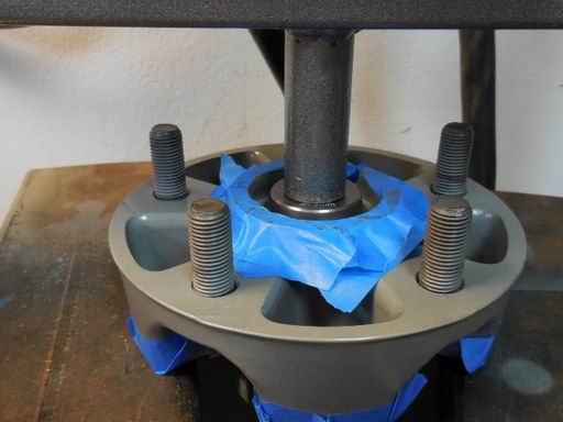
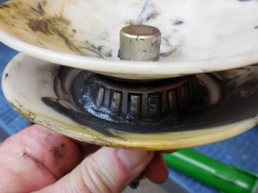
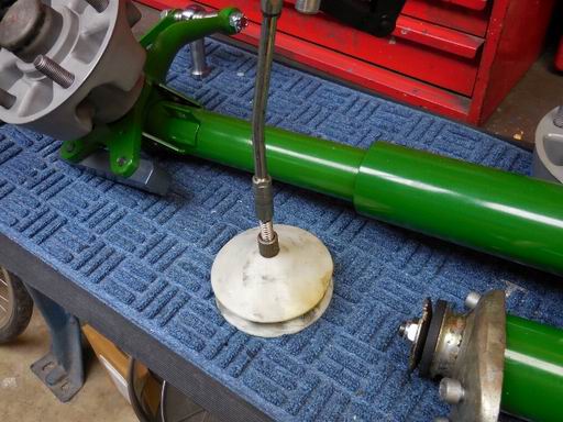
Posted by: Jeff Hail Dec 24 2014, 01:19 AM
Installing the seal then hub on the spindle.
Grease caps glass beaded and epoxy coated.
Poly Graphite bushings installed on the upper mounts.
Attached image(s)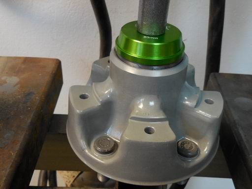
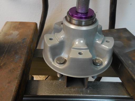
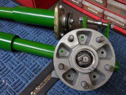
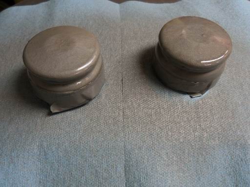
Posted by: 396 Dec 24 2014, 03:40 AM
Congrats and keep up the fantastic work. Enjoy a blessed holiday.
Posted by: mrbubblehead Dec 24 2014, 10:58 PM
Jeff,
what are you using for wheel bearing grease? It looks like swepco cv grease.
Posted by: Jeff Hail Dec 25 2014, 01:24 AM
Jeff,
what are you using for wheel bearing grease? It looks like swepco cv grease.
Short answer -
I've used Mobil 1, Valvoline 985 or 986 and Swepco 101. Will always use Moly based. I've never had a wheel bearing failure ever. Between those 4 I cannot tell the difference which is better. I like the Valvoline because it will flow but not sling.
I won't use blue based name brands from what I learned from motorcycle racing.
NEO, Redline and Krytox are great stuff but at 3x the price I have not seen bearings last any longer.
Swepco claims 500 degrees on the high end. If tapered roller bearings are seeing temps approaching 200 degrees a different problem is present that has nothing to do with grease unless its dry. That's too hot and usually way to tight.
I always pressure pack the bearings and fill the hub cavity 25% with grease. Any more and you can get grease purge. The inner seal is a good design from Porsche and the o-ring behind the bearing spacer stops everything else.
Lots of opinions on w/b grease. Choose your poison.
First key is properly seating the races, good lubrication and next setting the bearing load.
Merry Christmas
Attached image(s)
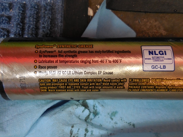
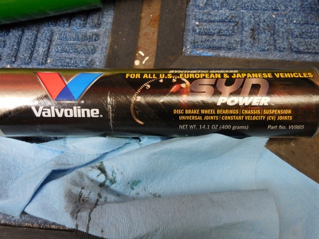
Posted by: Jeff Hail Dec 25 2014, 01:40 AM
Quaker came out with a white paper on grease formulation from data taken from Indy car racing a few years back.
Its really interesting when it gets down to drag caused by grease and power losses. Obviously its biased on Quakers product line but the data is pretty accurate from what I have seen compared to other petroleum suppliers.
http://www.quakerchem.com/wp-content/uploads/pdf/Our_Expertise/Resource_Center/White_Papers/sfhr_partnership_whitepaper.pdf
Posted by: CptTripps Dec 26 2014, 09:20 AM
I do love this thread...
Posted by: TJB/914 Dec 26 2014, 11:37 AM
Quaker came out with a white paper on grease formulation from data taken from Indy car racing a few years back.
Its really interesting when it gets down to drag caused by grease and power losses. Obviously its biased on Quakers product line but the data is pretty accurate from what I have seen compared to other petroleum suppliers.
http://www.quakerchem.com/wp-content/uploads/pdf/Our_Expertise/Resource_Center/White_Papers/sfhr_partnership_whitepaper.pdf
Jeff,
I love this thread, you are one smart/interesting/talented guy.
Tom
Posted by: Jeff Hail Jan 6 2015, 12:16 AM
Post assembly fact checking aka anal retentive quality control.
Checking runout after assembly. Spot on right and left. I lost sleep last night. Woke up and thought I gotta double check these after I put them together.
Attached image(s)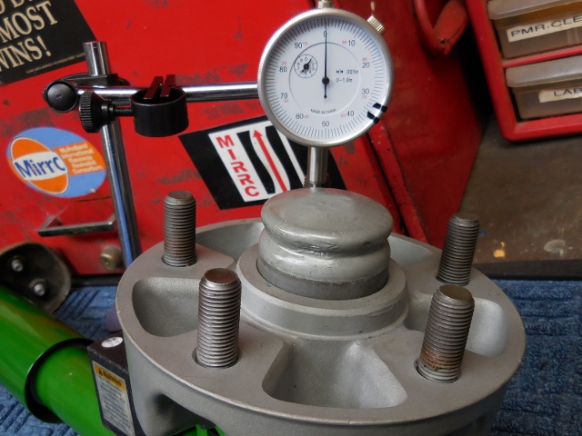
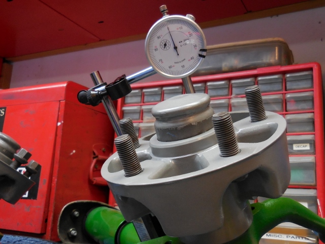
Posted by: Jeff Hail Jan 6 2015, 12:24 AM
Way back Machine
Have to weld up those trick rear backing plates. For some reason on 914's they are prone to fatigue cracks. This stuff is really thin. I measured it at 25 gauge at the thinnest area. My Miller 180 was turned down to under 1. About as low as it would go.
I'm not even going to use these on my car with the 911 rear parking brake mod.
Maybe someone here will end up with them? You never know? I might throw them in with the lot of parts going to the powder coater and then offer them up.
Attached image(s)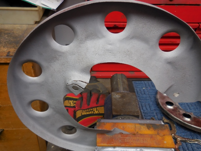
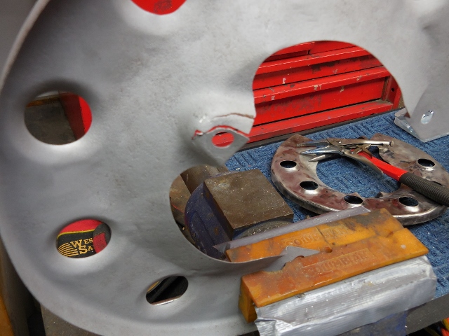
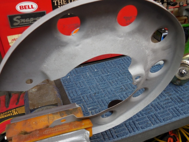
Posted by: Jeff Hail Feb 4 2015, 11:06 PM
As the lyrics from the Scorpions go: "The bitch is hungry she needs to tell...So give her inches and feed her well"
This whore has an enormous hole!
Attached image(s)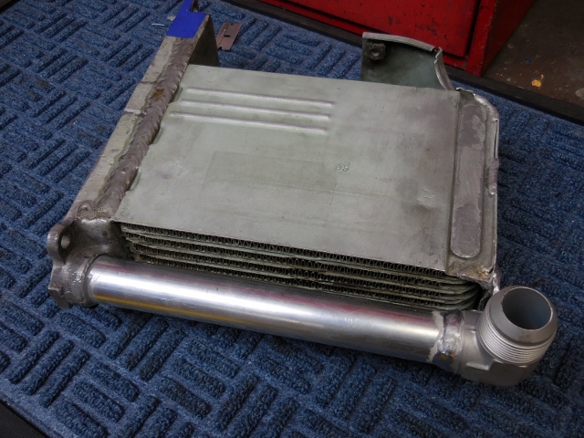
Posted by: FourBlades Feb 5 2015, 11:07 AM
Is that -16?
John
Posted by: johnhora Feb 5 2015, 11:10 AM
Way back Machine
Have to weld up those trick rear backing plates. For some reason on 914's they are prone to fatigue cracks. This stuff is really thin. I measured it at 25 gauge at the thinnest area. My Miller 180 was turned down to under 1. About as low as it would go.
I'm not even going to use these on my car with the 911 rear parking brake mod.
Maybe someone here will end up with them? You never know? I might throw them in with the lot of parts going to the powder coater and then offer them up.
Jeff...what did those backing plate come off??....Thanks...John
Posted by: Jeff Hail Feb 7 2015, 12:26 AM
Is that -16?
John
Yes sir John
Posted by: Jeff Hail Feb 7 2015, 12:27 AM
Way back Machine
Have to weld up those trick rear backing plates. For some reason on 914's they are prone to fatigue cracks. This stuff is really thin. I measured it at 25 gauge at the thinnest area. My Miller 180 was turned down to under 1. About as low as it would go.
I'm not even going to use these on my car with the 911 rear parking brake mod.
Maybe someone here will end up with them? You never know? I might throw them in with the lot of parts going to the powder coater and then offer them up.
Jeff...what did those backing plate come off??....Thanks...John
A 914.
Posted by: Jeff Hail Feb 7 2015, 12:29 AM
Back on metal.
Slicing some 16 guage
Sheet metal Origami
Attached thumbnail(s)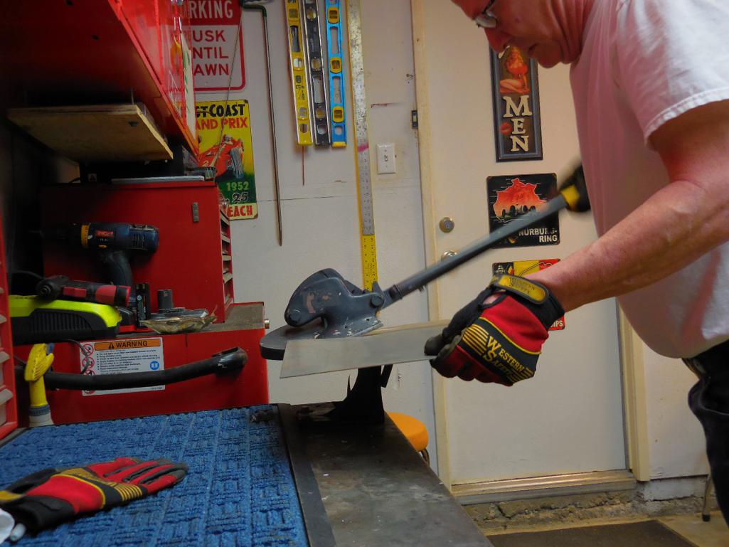
Attached image(s)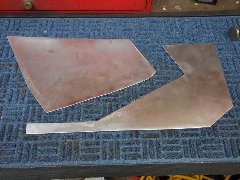
Posted by: Jeff Hail Feb 21 2015, 01:19 PM
I usually don't buy tools or equipment from HF other than disposables (nitrile gloves etc).
A couple of weeks ago I stopped in for a tent sale and picked up a "Scratch and Dent" welder cart. For a whopping $39.99 I nabbed the double wall cart with drawers. Its actually built pretty solid. It was missing the cable management hooks on one side but other than that I still can't find the scratch or the dent.
Attached thumbnail(s)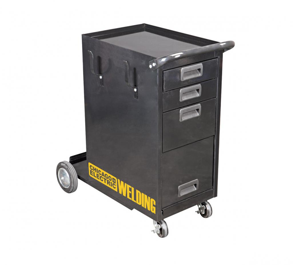
Posted by: Jeff Hail Feb 21 2015, 01:21 PM
A couple hours later and a little re-paint, clearcoat, a call to my Miller rep for some decals and now a decent matching cart.
Attached image(s)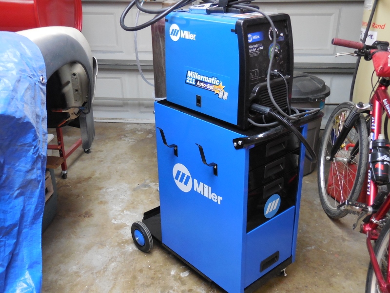
Posted by: KELTY360 Feb 21 2015, 01:30 PM
It even matches the blue tarp that's covering your car. Do we get to see what's underneath soon?
Posted by: Jeff Hail Feb 21 2015, 01:42 PM
It even matches the blue tarp that's covering your car. Do we get to see what's underneath soon?
I really don't use it as a tarp. I use it as a tent when I media blast small areas. Keeps the little meteors from getting all over the place. Everything falls to the floor. Sweep, sift and reload.
Posted by: mrbubblehead Feb 21 2015, 08:42 PM
nice score on the cart jeff. i ended up building my own.
http://s722.photobucket.com/user/mrbubblehead_photos/media/NCM_0009_zps8961c644.jpg.html
Posted by: Jeff Hail Feb 21 2015, 09:54 PM
Way cool. I was going to build one or buy a used pit cart but space is the final frontier.
Posted by: Maltese Falcon Feb 22 2015, 12:42 AM
Gotta have my drink holder for iced TEA !
Posted by: veekry9 Feb 23 2015, 08:17 PM
https://www.youtube.com/watch?v=vrlvqib94xQ
Simple.
Battery-weld
https://www.youtube.com/watch?v=PV5oLPLUzrM
Tools n more
Posted by: 914forme Feb 24 2015, 08:41 AM
Jeff, what color and who's product did you use for the green on your struts. Mine is original, faded and looks like crap.
And nice redo on the Harbor Freight Cabinet. If I payed $40 for the cart I would buy it also. Their tool chest seem to be the one thing they tend to over build. I have seen tons of people use their cabinets for the bases of benches, etc..
Posted by: Jeff Hail Feb 24 2015, 07:53 PM
[quote name='914forme' date='Feb 24 2015, 06:41 AM' post='2150933']
Jeff, what color and who's product did you use for the green on your struts. Mine is original, faded and looks like crap.
PPG 46180
You can buy rattle cans of Farm and Implement Green that are pretty close.
Posted by: 914forme Feb 25 2015, 07:56 AM
[quote name='Jeff Hail' date='Feb 24 2015, 08:53 PM' post='2151177']
[quote name='914forme' date='Feb 24 2015, 06:41 AM' post='2150933']
Jeff, what color and who's product did you use for the green on your struts. Mine is original, faded and looks like crap.
PPG 46180
You can buy rattle cans of Farm and Implement Green that are pretty close.
[/quote]
Ha, I should have know, JD Green.
I shop that isle all the time, Signal Orange happens to be very close to Minneapolis-Moline Gold.
Thanks for the tip.
Posted by: Jeff Hail Dec 22 2015, 10:41 PM
I did not realize how long its been since my last post. See what happens when you get to 50? Time flys when you're having fun.
Attached thumbnail(s)
Posted by: mepstein Dec 22 2015, 10:50 PM
Jeff - first post Oct 2 2007, 12:35 AM
Posted by: KELTY360 Dec 22 2015, 11:21 PM
Couple weeks?
Posted by: 396 Dec 23 2015, 09:02 PM
I did not realize how long its been since my last post. See what happens when you get to 50? Time flys when you're having fun.
Jeff,
Long time no talk. I'mhappy to see your enjoying life vs primary focusing on your 914.
All the best.
Posted by: cary Jun 18 2016, 09:13 AM
Mocked up the inner and outer firewalls to see how everything fits. No welds just loose.
Any words of wisdom when it comes to installing the complete lower engine side firewall still having both heater tubes in place. Seems like the standard practice is cutting it in half. But I was hoping there is a more sanitary approach. The tubes really hinder your ability to get it into place.
My first thought is to make some cuts in the flange so I have the ability to bend the field portion. ????
Posted by: Jeff Hail Jun 18 2016, 11:42 AM
It takes some jockeying to get it in with the air tubes not helping. I've had mine in and out for fitting of other pieces. Oddly it sometimes doesn't want to go in after it went in before.
To make matters even more jungle jimish the clutch and throttle conduits installed fight me all the way. I welded my PMS mount to the bulkhead out of the car which makes it impossible to bow the panel for insertion.
So you ask is there a way? For me the inner reinforcement goes last. Its pre fitted. I usually start the lower firewall in a semi tipped horizontal position (like a drawer and then bring it down like a garage door). You can tweek the sides where it meets the longs by bending the ears a bit vertically just inboard of the air tube exits. Then I insert the inner reinforcement which is a pain to get it under the tunnel lips.
Push everything forward.
I would pre fit everything a few times, trace any marks where you want to pre punch any holes for the welds, grind any weld landing zones clean at mating points. Self tapping screws secure the fit up.
There will be blood!
Posted by: doug_b_928 Jan 16 2017, 08:35 PM
Hi Jeff. In post #191 (linked below) you show your repair to the outer right wheelhouse. Newbie question: In places you have clecos on the original wheelhouse. So, did you leave little tabs on the repair piece and flange them so they'd tuck under the original wheelhouse, then drill the 1/8" hole through both for the cleco?
http://www.914world.com/bbs2/index.php?s=&showtopic=76791&view=findpost&p=1001455
Posted by: Jeff Hail Jan 17 2017, 07:34 PM
Hi Jeff. In post #191 (linked below) you show your repair to the outer right wheelhouse. Newbie question: In places you have clecos on the original wheelhouse. So, did you leave little tabs on the repair piece and flange them so they'd tuck under the original wheelhouse, then drill the 1/8" hole through both for the cleco?
http://www.914world.com/bbs2/index.php?s=&showtopic=76791&view=findpost&p=1001455
The repair panel was left a little large since I don't care to butt weld aprons or wheel houses. Pretty thin metal in those areas around the height of the battery tray so a little extra as a backer serves well to burn into. I used a small bead on on both sides instead of one fat hot bead since its visible from both sides.. The tail end of the repair panel was a butt weld to the wheelhouse. Both the panel removed and the repair panel have two larges hole in them for alignment of the outer console. The repair panel didn't overlay the old panel perfectly so the clecos were used to position it until I was satisfied where its permanent home would be versus having to use self tapping screws in, out, in out, in out. Just saved time in the fit up.
Posted by: doug_b_928 Jan 17 2017, 08:12 PM
That's very helpful, thanks Jeff.
Posted by: Jeff Hail Feb 24 2017, 05:55 PM
Enjoy!
https://youtu.be/3kLOnEKbuW0
Posted by: KELTY360 Feb 24 2017, 06:42 PM
Enjoy!
https://www.youtube.com/watch?v=YEMyy4jWmA4
That was fun! That road surface looks really rough. Was it that way back in the day?
Are you still working on the 914?
Posted by: Jeff Hail Feb 26 2017, 12:30 AM
Enjoy!
That was fun! That road surface looks really rough. Was it that way back in the day?
Are you still working on the 914?
Its been paved completely from the 101 fwy to Encino Hills Drive once in my lifetime. Its been patched and paved in sections depending on which celebrity cries the loudest or if a washout occurs. Its always been pretty rough. Pot holes are good for the reflexes.
Yup still working on the 914 as much as I can. Life happens and somethings take a back seat.
Posted by: Jeff Hail Mar 20 2017, 08:41 AM
Ran into Aaron Schwartzbart. Trailer got a flat tire on his way home from the track. Interesting guy: ex rocket scientist turned pastor. Does a great job of getting guys off of street racing and onto the track.
Nice car with a 383 stroker and a 930 trans. There is a YouTube video of this car doing a 180mph dyno pull.
Attached image(s)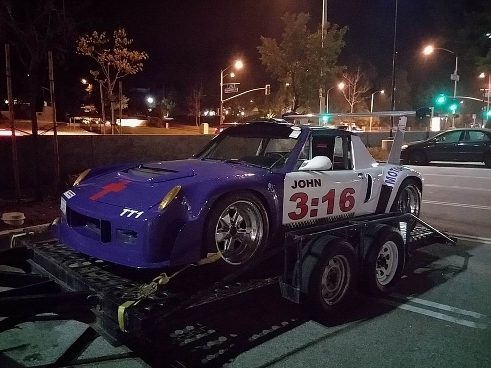
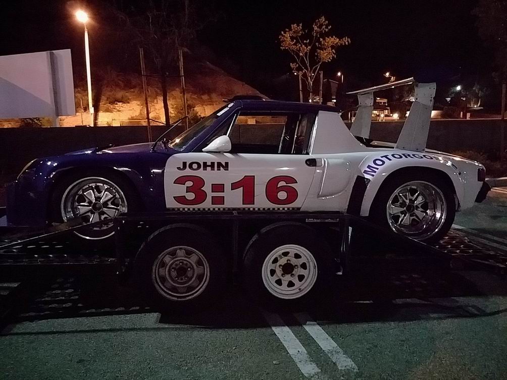
Posted by: sb914 Mar 20 2017, 08:52 AM
Beautiful car !!
Posted by: tygaboy Mar 20 2017, 09:08 AM
Interesting rear wing location. I understand it's critical to get the wing up high. This one's mounted farther forward than most I've seen.
I'm not smart enough to know anything but I wonder how that might impact aero.
Farther back = more leverage?
Either way, I like the aesthetic. Great looking car (it's giving me some ideas for mine!)
Posted by: Tbrown4x4 Mar 20 2017, 10:13 AM
My guess is that the location is above the suspension/tire contact patch.
Posted by: tygaboy Mar 20 2017, 11:45 AM
My guess is that the location is above the suspension/tire contact patch.
Yep, I get that. I was just wondering:
if you put 10 lbs (of force) directly above the contact patch, you'd see 10 additional lbs at the contact patch (less whatever % transfers to the front axle line). But if you put 10 lbs at the end of the trunk, would that give you more at the contact patch?
I'm sure there are formulas for this sort of thing.
Way off topic, sorry... back to your regularly scheduled awsomeness of Jeff's work!
Posted by: ndfrigi Mar 20 2017, 12:00 PM
Ran into Aaron Schwartzbart. Trailer got a flat tire on his way home from the track. Interesting guy: ex rocket scientist turned pastor. Does a great job of getting guys off of street racing and onto the track.
Nice car with a 383 stroker and a 930 trans. There is a YouTube video of this car doing a 180mph dyno pull.
Surely a Pastor that send or share the bible verse! John 3:16. God Bless you!
Posted by: NS914 Jun 29 2018, 09:45 AM
Hey Jeff,
Did you ever finish your 914....and what about that Headlight Solution....love the work on the brakes!
Grant
Posted by: mbseto Jun 29 2018, 02:40 PM
My guess is that the location is above the suspension/tire contact patch.
Yep, I get that. I was just wondering:
if you put 10 lbs (of force) directly above the contact patch, you'd see 10 additional lbs at the contact patch (less whatever % transfers to the front axle line). But if you put 10 lbs at the end of the trunk, would that give you more at the contact patch?
You'd be stealing it from the front wheels. I.e., the leverage from moving the wing back would be using the rear wheels as a fulcrum and lifting that extra force (weight) off the front wheels.
Posted by: Jeff Hail Jun 29 2018, 09:06 PM
Hey Jeff,
Did you ever finish your 914....and what about that Headlight Solution....love the work on the brakes!
Grant
Still a work in process. Little work here and there. Its not my first priority right now.
In May 2016 I was thrown a hard fast curveball.
My heart stopped three times on three separate days over one month. Wasn't a heart attack or stroke. No A-Fib. No brain damage. No clogged arteries. Not orthostatic hypertension. Strong heart: normal rhythms and waves. I eat healthy, stay fit, 4 beers in 3 years, avoid drama and toxic people. Still wonder why this happened?
After the first time cardiologist hooked my up to a 12 lead for 24 hours, nada nothing. CT's nada. Multiple MRI's nada. Sent me home with a 5 lead flight recorder.
Over the next three weeks two more times. Imagine your heart not beating for two minutes? Doctors refer to it as "Zero Time" when the heart does not pump oxygenated blood to the brain. Everything stops lights out I'm dead.
Cardiologist: "Hey Jeff congratulations you died three times and lived to tell about it".
Tests, tests, tests. The Tilt Table test was not fun. Its performed in a full cardiac unit with two Docs and two ER nurses. I'm thinking this is serious stuff. Its: 6:00am and the room is kept 60 degrees which I found odd.
The TTT is designed to make you black out. Good part is I didn't pass out. Humans are not designed to stand still for 1 hour upright at a 70 degree angle (yes 70 degrees because your body and inner ear cant tell if you are up or laying down). It is designed to increase your heart rate by constriction (or lack of) in the lower body until it just doesn't pump anymore blood or pool down into the legs.
Test begins laying down for 15 minutes while they baseline your vitals. Then they tip you up at 70 degrees for 1 hour until time up or you go out which ever comes first. Old people are usually only tested for no more than 20 minutes and only make it about 10 minutes before they go down. The spooky part is when you start the test they stick a butterfly in your arm connected to a big syringe loaded with quite a bit epinephrine.. and tape fib paddles to your ribcage. The table is parked next to fully stocked red roll away SnapOn CRASH CART.
Doc "were going to try to make your heart stop, the epinephrine along with a few joules going through these paddles will jump start your heart if it stops. Its safe we do this everyday and your in great hands. We will bring you back to life. Stand still, no moving, don't pump your legs and no talking". The whole time I'm visualizing the scene with Uma Thurman in Pulp Fiction getting stabbed in the tit with a really long needled epi-injector plus jumper cables!
This was where I learned to really trust the cardiologist. ( seriously )
I'm a bit of an adrenaline junky, like I need more epinephrine? I don't think so Doc. At the 20 minute mark you start getting warmer because the heart is working harder. At 30 minutes you start breaking a good sweat and everyone starts watching you really closely. Then the Doc says "Jeff if you feel like you are going to go out just let it happen, we will bring you back to life". I can see the display with my vitals, heart rate like 160bpm now ( remember its designed to make this happen). At 45 minutes one nurse is on my right at the ready to push the plunger on the liquid high octane adrenaline, the other nurse on my left is ready to drop the table down flat. Doc has his finger on the jumper cable button, other Doc is watching my eyes for roll up not saying a word.
I can tell its close, I can feel it in my legs. At one point I'm thinking happen already get it over with so I can get out of here. The human body has a built in safety mechanism. Various baro-sensors in the body detect pressure, too much or lack of. Through the vagus nerve it communicates with what's called the 10th cranial nerve via parasympathetic control with blood vessels, arteries etc so the body can route flow and volume to keep pressure regulated.
Then the medical establishment comes up with that neat hat trick using the 70 degree posture trick to fool that body system to make it all fail.
Part of that built in safety system as any pilot or someone who has experienced high G-forces is our toes and feet and they did not make me take my shoes off. I start curling my toes and pushing with my feet hard to where it hurts. I'm trying to not make it obvious because its considered cheating the test. My heart rates starts to come down to 130. Everyone in the room starts to relax. Nice nurse on my left taps my arm and says "your doing great only 10 more minutes". What 10 more minutes? Are you frigging kidding me?
Now I'm getting spanky, my own adrenaline has kicked in. Listen the only thing going out is the five of us for drinks when we get done? They thought that was funny.
Doc asks are you skrinching your toes? Damn right I am, nobody is going to black out today especially me! "Doc, that's a good sign the vasoconstriction system is working as it should... see if you can keep it up for another 5 more minutes". Test winds down. My body temperature is 101 degrees and now I know now why they keep the room at 60. They drop the table down flat. Done. Made me drink 2 liters of water before I could stand up on my feet.
Two minutes of zero time that changed everything from that moment on. I'm ok. Still do not know what caused it. Its a mystery. Stumped more Doctors because they thought it was syncope at first. Nope syncope only lasts a few seconds. Not POTS either...
Cardiologist thinks is was hypovolemia. Not enough blood. Kind of like when a Berkley Jet on a boat cavitates and no longer pushes water out the nozzle to push the boat forward. Hell of an analogy isn't it? I drink 5 liters of water per day now. Piss like a herd of race horses. Its supposed to keep my blood volume high. Easy fix considering the alternative. Its similar to how people die from extreme dehydration. Dehydration was ruled out but symptoms are the same.
I have a great Cardiologist who is also good friend now. The guy runs 16 miles day. He had to stop midway twice during this years LA Marathon to assist runners who were passing out and needed medical attention.. and he still finished the marathon. Yup that's my Doc who everyone saw on TV saving people who failed to train and condition themselves. He wont admit it when I tell him he is an adrenaline junky too just on a different path.
Here I am today. A very different person. How I approach and look at life. Hearts do not beat forever. I'm quieter and live on my own Hawaiian time now. It works. I look at this experience as a blessing. Every day is a gift and that's how everyone should look at it. No one ever taught me how to give up. I mean that.. I really don't know how to give up. Gods is not done with me on this earth. The universe has a way of getting your attention.
I have not stopped working on my 914. Its just simmering for now. Been enjoying some other non transportation related things though.
Life is long.
Life is not a dress rehearsal..
Play hard and get dirty!
Posted by: Jeff Hail Jun 29 2018, 09:18 PM
and one more thing!
No pity, not looking for sympathy. I'm not going on the dead fairy list any time soon.
Don't be clogging up my thread. Stuff happens in life.
Posted by: altitude411 Jun 29 2018, 09:25 PM
Fantastic writing and some serious content to go along with it. Thanks for the update Jeff. Congratulations on being a contestant on Stump the Cardiologist. Keep winning the game.
* sorry about this clot in your thread.
Posted by: sixnotfour Jun 29 2018, 09:28 PM
Life is long.
Life is not a dress rehearsal..
Play hard and get dirty!
Posted by: Jeff Hail Jun 29 2018, 09:43 PM
I am also a representative of "Spirit of Can".
There is a saying in Hawaii:
"If can, can. If no can, no can."
CAN
Its not a question, just the answer.
Posted by: Maltese Falcon Jun 29 2018, 10:01 PM
Good to see you back here Jeff Yeah Mulholland still safer at night, what you don't see in the vid are the numerous bicyclists on that road like 6am to sundown; just not safe for anyone involved. Road condition= permanently awful from the Hollywood Bowl and west as far as Coldwater Cyn. Way better off ...run any track event and enjoy a safer environment !
Love that John 3:16 racer ! In-n-out burger is also big on spreading the Gospel...just look under any drink cup and be blessed
Take care and keep fab'ing
Posted by: rick8928 Jul 30 2018, 05:16 PM
I am also a representative of "Spirit of Can".
There is a saying in Hawaii:
"If can, can. If no can, no can."
CAN
Its not a question, just the answer.
"Do or Do not. There is no try."
Those pesky Hawaiians are always copying Yoda.
Posted by: Jeff Hail Jul 30 2018, 05:38 PM
I am also a representative of "Spirit of Can".
There is a saying in Hawaii:
"If can, can. If no can, no can."
CAN
Its not a question, just the answer.
"Do or Do not. There is no try."
Those pesky Hawaiians are always copying Yoda.
Pidgin can be fun or it can stump. English-based creole spoken in Hawaiʻi
Posted by: 76-914 Jul 31 2018, 09:59 AM
Keep plugging away and never stop my friend!
Posted by: Superhawk996 Aug 25 2018, 05:19 PM
I'm about to begin a similar endeavor on a 73' 2.0L widebody.
This thread has been a tremendous source of information and inspiration.
Keep going!! CAN is the only option.
Posted by: Curbandgutter Aug 26 2018, 10:48 AM
Interesting rear wing location. I understand it's critical to get the wing up high. This one's mounted farther forward than most I've seen.
I'm not smart enough to know anything but I wonder how that might impact aero.
Farther back = more leverage?
Either way, I like the aesthetic. Great looking car (it's giving me some ideas for mine!)
@http://www.914world.com/bbs2/index.php?showuser=19241 the reason for the location of the wing is so that the wind load going down will go right over the rear suspension and transfer straight down to the wheels without any additional torque on the car that will try to lift the front wheels. For example, if you imagine putting the wing out behind the car 10' yes 10' and then you hypothetically attach it to the car, and then you put a force vertically down, do you see how it would force the back end down but it would also use the rear wheels as a fulcrum point and would try to lift the front of the car. Do you see it? Well now if you start to move that wing closer and closer to the point where it sits right over the rear wheel, can you see that it will get to a point where it sits right on top of the fulcrum and will have the same downforce but it will not lift the front of the car up?? That is why he did it that way. If I ever put a wing on my car, that will be the location! Hope that helps. Sorry for getting off post.
Posted by: doug_b_928 Dec 30 2018, 07:35 PM
Happy New Year Jeff. In post #245 on p. 13 of your thread, you document applying Wurth Seal/Fix to the underside of the door sill and around the sill triangles. Would the Wurth sprayable seam sealer work as well as the Seal/Fix in that location? Also, do you apply a thin amount of seam sealer on the top side seam where the sill meets the inner rocker/longitudinal (to prevent water from getting under the sill and being trapped underneath by the sealer that has been applied from the bottom side)?
Posted by: Jeff Hail Dec 30 2018, 08:32 PM
Happy New Year Jeff. In post #245 on p. 13 of your thread, you document applying Wurth Seal/Fix to the underside of the door sill and around the sill triangles. Would the Wurth sprayable seam sealer work as well as the Seal/Fix in that location? Also, do you apply a thin amount of seam sealer on the top side seam where the sill meets the inner rocker/longitudinal (to prevent water from getting under the sill and being trapped underneath by the sealer that has been applied from the bottom side)?
Hey Doug! Happy New Year.
Sitting here watching the Jeff Beck story:"Still on the Run".
Sprayable will work as well although not much volume comes out of the gun at low pressure.. After primer: Mine was a thin bead and then sprayed over with the Wurth (spit gun). As far as between the sill top I just used a copious amount of weld through primer on both surfaces since its sacrificial and has a low melt temperature. I sprayed a thin coat second time after welding to hit the edge of the sill and let it creep in.
Posted by: doug_b_928 Dec 30 2018, 09:35 PM
Thanks very much Jeff!
Posted by: preach Dec 31 2018, 01:51 PM
Amazing thread Jeff.
Posted by: ssuperflyoldguy Sep 18 2019, 01:03 PM
Amazing thread Jeff.
Best. Thread. Ever. Thank you for all your efforts helping us
Posted by: stevegm May 7 2020, 06:53 PM
When butt-welding along with good weld penetration the key is the grinding and finishing process.
I begin with a spot weld grinding disc to take the crown of the weld down to just above panel height. Move slow and let the panel cool. A grinder will warp thin sheetmetal just like overheating while welding.
Then I use a 3 inch 36 grit disc on a angle die grinder to take the crown down a little more.
Then I switch to a 6 inch flat flap disc and follow the crown back and forth eliminating any high spots.
Question - How do you finish the seam on the inside of the quarter panel? I would imagine that getting in there to grind it smooth would be difficult. Do most people just knock it down a little bit, and leave it rough since it’s on the inside of the fender?
Attached image(s)


Posted by: Jeff Hail May 7 2020, 09:35 PM
When butt-welding along with good weld penetration the key is the grinding and finishing process.
I begin with a spot weld grinding disc to take the crown of the weld down to just above panel height. Move slow and let the panel cool. A grinder will warp thin sheetmetal just like overheating while welding.
Then I use a 3 inch 36 grit disc on a angle die grinder to take the crown down a little more.
Then I switch to a 6 inch flat flap disc and follow the crown back and forth eliminating any high spots.
Question - How do you finish the seam on the inside of the quarter panel? I would imagine that getting in there to grind it smooth would be difficult. Do most people just knock it down a little bit, and leave it rough since it’s on the inside of the fender?
Angled die grinder with a 2 or 3 inch disc. A 3 inch flap (water wheel type) will take the back side down. Just need to hit the high spots. The butt weld done right does not leave much of a proud weld on the back.
Powered by Invision Power Board (http://www.invisionboard.com)
© Invision Power Services (http://www.invisionpower.com)