Printable Version of Topic
Click here to view this topic in its original format
914World.com _ 914World Garage _ The start of my 2.0 build
Posted by: MrKona Dec 14 2007, 09:19 PM
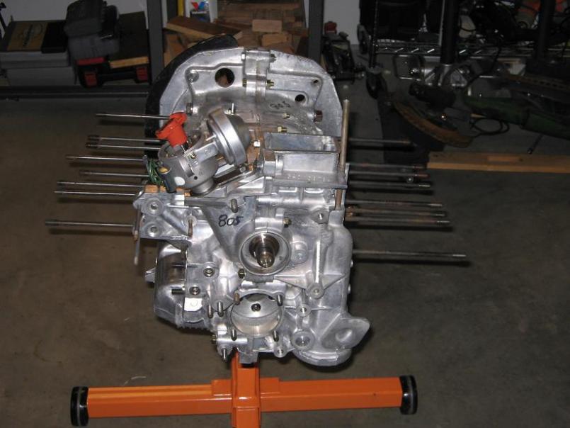
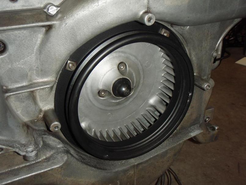
I talked about building up a 2.0 last winter, and now I'm finally going to do it. This is my first engine build, hence it'll be conservative and relatively stock. My only plan with the car is to have a nice, reliable, well constructed engine. I thought about a 2056, but I finally decided to stay with 94mm cylinders. I really don't want to have to tweak with FI or fiddle with cam selection right now. I've read that Jake's 9550 cam is excellent, but also that it produced dirty emissions. I'd like to keep this engine as clean as a type 4 can be. I'm also a little confused if Jake is even selling cams at the moment, so I've just decided to go with a stock grind.
My current engine is a PO rebuilt 1.8 with hydraulic lifters (with one that won't prime, sounds horrible, I can't wait to be done with them).
Highlights:
GA case
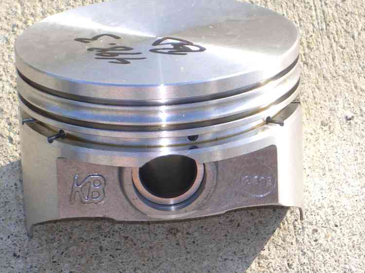
Stock displacement (with new Euro spec pistons)
Stock grind Webcam and with solid lifters (both new)
For now, I'm going to cannibalize the rebuilt 1.8 heads from my current engine, unless I find a deal on decent rebuild 2.0 heads during the build. I would love to buy a pair of Raby heads, just can't swallow the extra two grand at the moment.
L-jet fuel injection from my 1.8. (I have some issues to work out here, running really rich. No vacuum leaks that I can find. I have to check the fuel pressure - I'm thinking either AFM or pressure regulator as next areas to check). From what I've read on many threads here and other sites, the L-jet can handle up to a 2056 displacement.
I'll keep this thread updated this winter as I work through this rebuild. I don't know how long a project this will be or how quickly I may get it done.
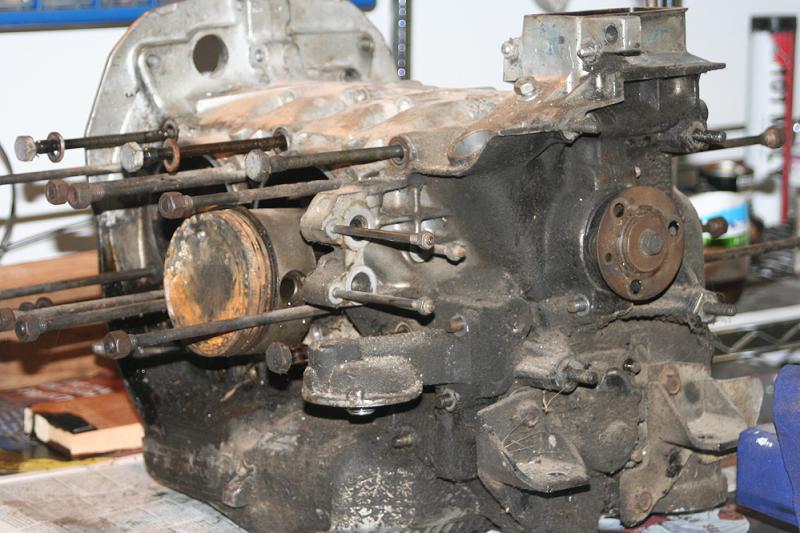
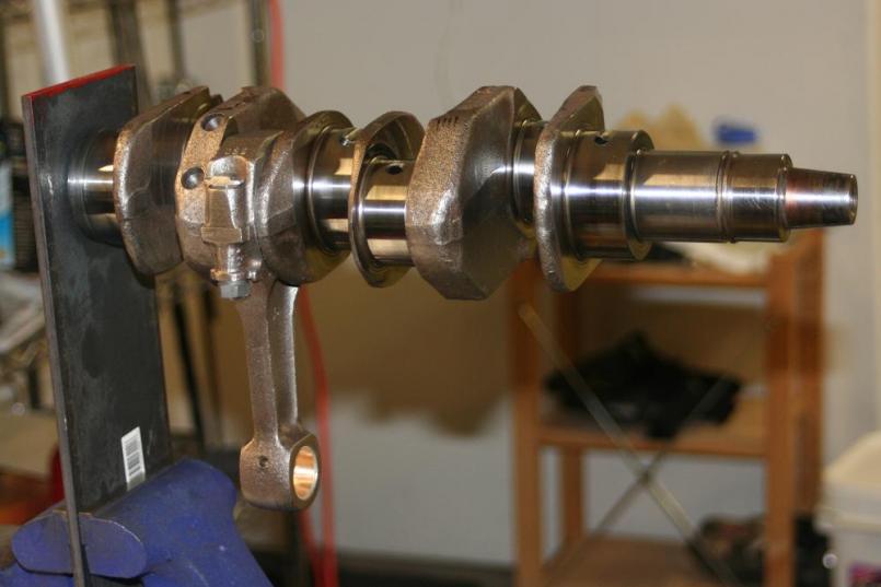
Current progress: Jake Raby rebuild DVD - Check. Tom Wilson's book - Check. I've split the case and and planning on bringing the case, crank, and rods for reconditioning to Dan Hall's Machine Shop here in Portland. After reading various forums, this appears to be the Type IV specialist in this area. Brand new Euro-spec P/C set - Check! 
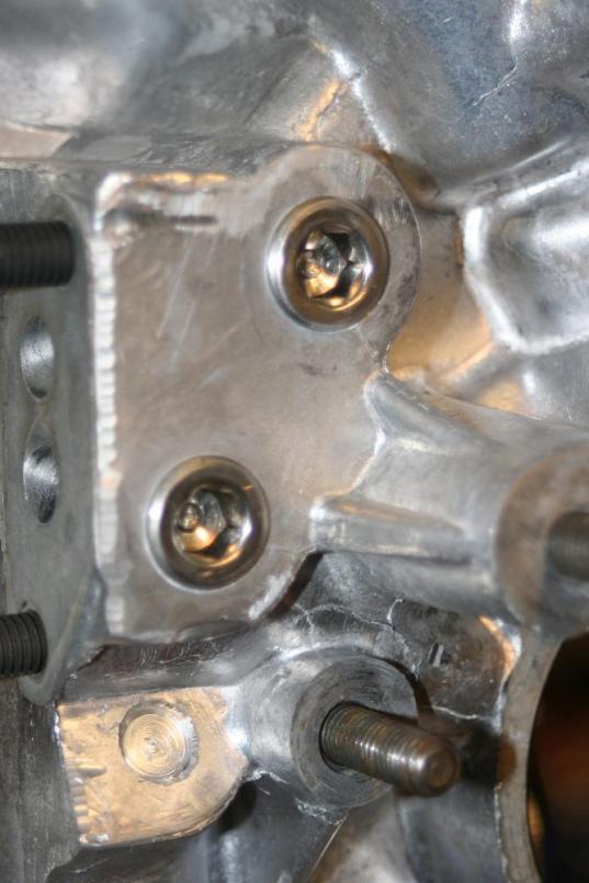
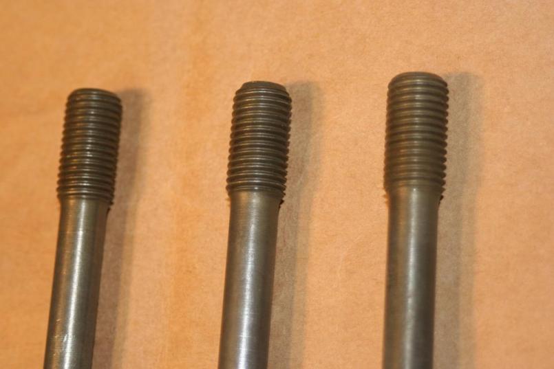
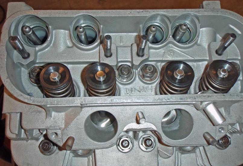
So now for my first question: Regarding the existing cylinder studs, Tom Wilson writes, "Unless you're installing case savers, don't remove the cylinder studs from the case. Doing so has no purpose, but does wear the potentially troublesome case threads, takes time, and stresses the studs" (p. 76).
In the assembly section, he states "If the cylinder studs were removed for some reason, install them now. Apply Permatex 3H to their threads to stop oil leaks" (p. 120).
I don't know the history of this case. I don't know if there was leakage at the head studs. Should I remove the studs, and reinstall with Permatex (after the case comes back from the machine shop, obviously) as a precaution to prevent potential leakage? Or should I just leave them be as is? Does it really put that much stress on the case to remove them, or is Wilson referring primarily to the Type I-III magnesium cases? I am leaning to toward remove and reinstall, as I strongly intend for this engine to be leak-free.
Lastly, as I work through this process, I welcome and encourage comments. Please, if you see something I'm doing wrong, or have advice for me, give it to me! I can probably use it! 
Attached image(s)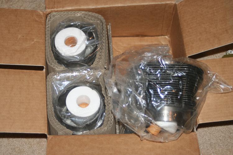
Posted by: MrKona Dec 14 2007, 09:25 PM
Oh yeah, forgot to mention that I bought the case without heads, as is pictured.
Posted by: toon1 Dec 14 2007, 10:12 PM
Where did you hear the 9550 cam put out "dirty emissions"?
You would be doing yourself a great injustace NOT putting in a 9550 or any of Jakes other grinds. They are all known to outperform the stock cam.
Guy's have claimed their engins ran 20* cooler with the 9550 installed.
Good luck with your build, rethink the cam. 
Just my .02
Posted by: Dan (Almaden Valley) Dec 14 2007, 10:25 PM
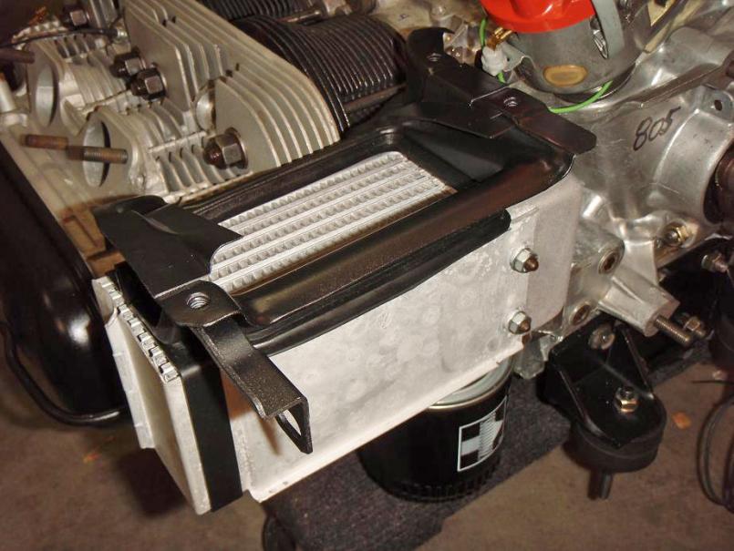
I built a 2056 last winter.
Mahle 94 MM barrels punched out to 96mm
96mm KB aluminum pistons
9550 cam
adjusted MPS by Blyseng....
put it all together and it runs very nicely...
won the improved class of the 914CUP this season as well as my AX class in my local PCA AX series (GGR)
running against BoxsterSs and 996s and 993s on sticky tires.
if you are going to do a build you might as well build something that gives you a little more kick...the cost really isnt prohibitive.
I built my 2056 for ~$2K including parts and machining
Rebuilt 2.0L heads with new valves, springs, guides and cracks welded
machined crank
machined (align bored) original 2.0L case
lightened and balanced flywheel/pressure plate
it isn't tough to do it right and give yourself a bit more hp....~115 now instead of ~90 stock.
I am running stock D-jet.
Attached image(s)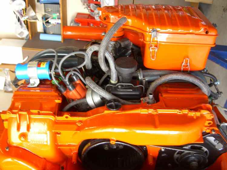
Posted by: MrKona Dec 14 2007, 11:16 PM

Where did you hear the 9550 cam put out "dirty emissions"?
You would be doing yourself a great injustace NOT putting in a 9550 or any of Jakes other grinds. They are all known to outperform the stock cam.
Guy's have claimed their engins ran 20* cooler with the 9550 installed.
Good luck with your build, rethink the cam.
Just my .02
Good question - I could have sworn I read it in a post somewhere by a very reputable member of this club. Now I can't find it. Unless I find that post, I retract this statement. Jake - If you're reading this, I did not mean to slander your cam...
Posted by: MrKona Dec 14 2007, 11:21 PM
I built a 2056 last winter.
Mahle 94 MM barrels punched out to 96mm
96mm KB aluminum pistons
9550 cam
adjusted MPS by Blyseng....
put it all together and it runs very nicely...
won the improved class of the 914CUP this season as well as my AX class in my local PCA AX series (GGR)
running against BoxsterSs and 996s and 993s on sticky tires.
if you are going to do a build you might as well build something that gives you a little more kick...the cost really isnt prohibitive.
I built my 2056 for ~$2K including parts and machining
Rebuilt 2.0L heads with new valves, springs, guides and cracks welded
machined crank
machined (align bored) original 2.0L case
lightened and balanced flywheel/pressure plate
it isn't tough to do it right and give yourself a bit more hp....~115 now instead of ~90 stock.
I am running stock D-jet.
Very, very nice... I've already got my Euro-spec Mahles, so no turning back now, I'm going to use them. I'm committed to the Mahles, but feel good about it... Part of me says "Keep it German". I know that's not rational, but I'm admittedly a bit strange in some respects.
Posted by: Jake Raby Dec 14 2007, 11:31 PM
Cool.. But the stock combo certainly isn't the most optimum for today's driving and fuels.
Call me.
It's all in the combo. Many times trying to avoid problems (that don't really exist) only creates compromises, spends more money and still creates problems that you must overcome. Trying to avoid issues creates a mind set that breeds issues, it is mechanical and you must have the desire to whip it's ass and that must begin right now if you intend to get your money's worth and not be under the decklid every weekend....
NO!!!! Who said it ran dirty? Who failed an emissions test with it? Send me a link!
The 9550 manipulates the stock FI system very well and the results people have gotten with it prove this. Cooler running, more MPG, broader power and an extended RPM range are it'c characteristics- Dirty emissions is not!
OK. No p[roblem, add some CR, couple that to a 9550 and the engine will run cleaner than it was designed to 35 years ago.
Yes, but only with complete valve train kits of compatible parts.
See this comprehensive presentation I created to go over the selection oc components. Here is the link to the version that can be viewed with IE7
http://rdtlabs.com/Presentations/t4engcam.mht
And here is the much better version for Poer Point users.
http://rdtlabs.com/Presentations/t4engcam.pps
There should be no questions remaining after viewing the presentation with it's illustrations.
See this thread on my forum for specifics on the program that we have created for 2008
http://forums.aircooledtechnology.com/showthread.php?t=1929
Since at least one of the 11 variables dictating the necessity of valve train geometry being reset will be encountered sticking with the stock cam isn't going to make the engine any easier to build. The cams cost the same as well, so there won't be any money saved either..
The stock cam is the first thing I throw away....
Can't blame you there...
Highlights:
Better check those case decks! the GA case is the worst!
If you haven't bought those yet, the 96s give so much more with no negative aspects.
The stock web grind isn't a 914 spec :"stock grind"
According to who rebuilt them you might buy a nightmare.
I have one pair of my personal 2.0 heads that I'll be selling soon, these are not our new castings but are built to our specs and done Len's way back to stock specs with new valve train and upgraded parts.
Yes, L jet seems to like a 2056 better than a stock displacement engine.
I'll keep this thread updated this winter as I work through this rebuild. I don't know how long a project this will be or how quickly I may get it done.
Cool.. Feel free to seek assistance on my forums as well, if you do go the more efficient route.
I concur.
I concur. But I use loctite 565
This is really a non issue and you have much bigger things to worry about. I haven't had a stud leak in about 12 years-
Good mind set.
I'd like to see you get the most for your money and what we are doing just plain works.
Posted by: blitZ Dec 15 2007, 08:15 PM
I did my first engine rebuild the summer of 76 with a budget project using Jake's 96mm cylinder and piston kit and the 9550 cam. Tweaking the Djet to fit these mods is simple and the results are quite worthwhile. It's a totally different car with the extra hp and torque, the engine is very solid and reliable. I don't think you will regret making these minor upgrades on your first rebuild.
Posted by: Bleyseng Dec 15 2007, 11:53 PM
I did my first engine rebuild the summer of 76 with a budget project using Jake's 96mm cylinder and piston kit and the 9550 cam. Tweaking the Djet to fit these mods is simple and the results are quite worthwhile. It's a totally different car with the extra hp and torque, the engine is very solid and reliable. I don't think you will regret making these minor upgrades on your first rebuild.
I have put the 9550 cam in three engines now and the cooler CHTs alone are worth it!
20-50F cooler than stock is a hellva deal when these stock engines hit 400F easy.
Posted by: MrKona Dec 24 2007, 05:57 PM
Small progress update.
Parts - I'm buying a rebuilt set of 2.0 heads from Jake. Also will be going with Jake's valvetrain upgrade kit (with cam) and cam gear and new oil pump. Right now, I plan on sticking with my already acquired 94mm Euro-spec Mahle P/Cs. Since I don't have to decide for a while whether to bore them out to 96mm with KB pistons, I'm keeping that option on the back burner. If anyone knows of a good machine shop they would trust not to mess up a new set of Mahle cylinders, please let me know (just in case).
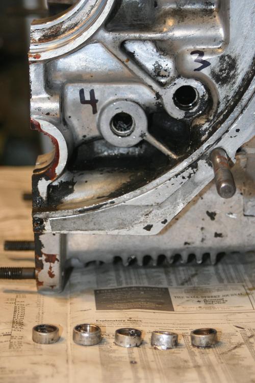
I took the case to the local self-serve car wash to clean it up enough to work on it. This afternoon, I removed the recommended five factory galley plugs. They came out quite easily. Pretty scary to think of not changing these out! Next, off to the machine shop!
Merry Christmas and Happy Holidays to everyone! 
Attached image(s)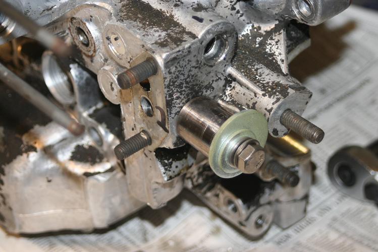

Posted by: hydroliftin Dec 24 2007, 07:04 PM
I plan on sticking with my already acquired 94mm Euro-spec Mahle P/Cs. Since I don't have to decide for a while whether to bore them out to 96mm with KB pistons...
You are probably better off buying a set of used cylinders if you plan to bore them out and buy new KB pistons. The used cylinders have already been heat cycled so you avoid stability issues, and you have a new set of mahle P/Cs that you could sell for a lot more than you would pay for the used cylinders. Using the new Euro-specs is also not a bad idea either. You miss out on a few cc's and compression might be lower than you would get with the 2056, but it still makes a nice engine.
Posted by: MrKona Dec 24 2007, 07:32 PM
I plan on sticking with my already acquired 94mm Euro-spec Mahle P/Cs. Since I don't have to decide for a while whether to bore them out to 96mm with KB pistons...
You are probably better off buying a set of used cylinders if you plan to bore them out and buy new KB pistons. The used cylinders have already been heat cycled so you avoid stability issues, and you have a new set of mahle P/Cs that you could sell for a lot more than you would pay for the used cylinders. Using the new Euro-specs is also not a bad idea either. You miss out on a few cc's and compression might be lower than you would get with the 2056, but it still makes a nice engine.
Thanks. That's very good food for thought. I'm going to keep my eyes and ears open for used Mahle cylinders...
Posted by: MrKona Mar 19 2008, 12:10 AM
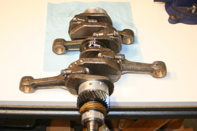
Update on my engine build... The case, crank, and rods have all come back from the machine shop and everything checked out OK for standard bearings. Case deck registers were OK. Crank was polished, and rods were rebushed.
I drilled and tapped the oil galleys.
I spent a lot of time carefully removing rust from the crank and rods.
Last night I Plastigaged the rod to crank clearance (although I read on the boards that some people think plastigaging isn't optimum to measure clearance, I'm in this to learn. Clearance measured .0015" at each journal, within spec.
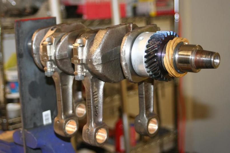
Tonight I installed the timing and distributor gears back on the crank. My wife was my assistant in getting the snap ring back on and seated. I had her watch that section of Jake's video so she knew exactly what we needed to do.
I'd like to install the rods now, but I need to find a 14mm socket with a little better clearance between the rod and rod nut. My Craftsman socket is a little too fat and I can't get a good grip on the nut.
Parts update: I picked up a few items from Jake, including a 9550 cam and valvetrain upgrade kit, and a pair of low mileage refreshed heads. I also found 1.7 rockers for the 911 swivel head adjusters. The rockers cleaned up nicely.
Attached thumbnail(s)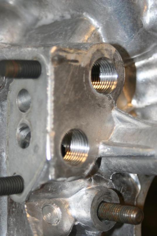
Attached image(s)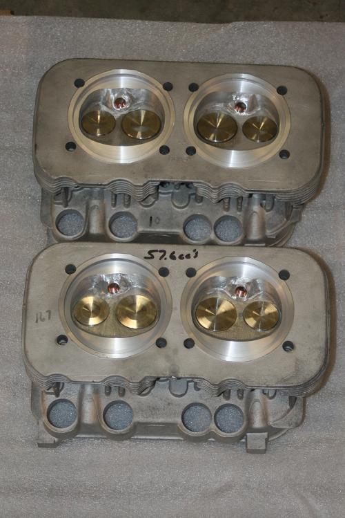
Posted by: MrKona Mar 19 2008, 12:12 AM
More...
Attached thumbnail(s)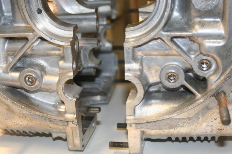
Posted by: MrKona Mar 19 2008, 12:15 AM
More...
Attached thumbnail(s)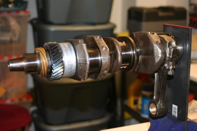
Attached image(s)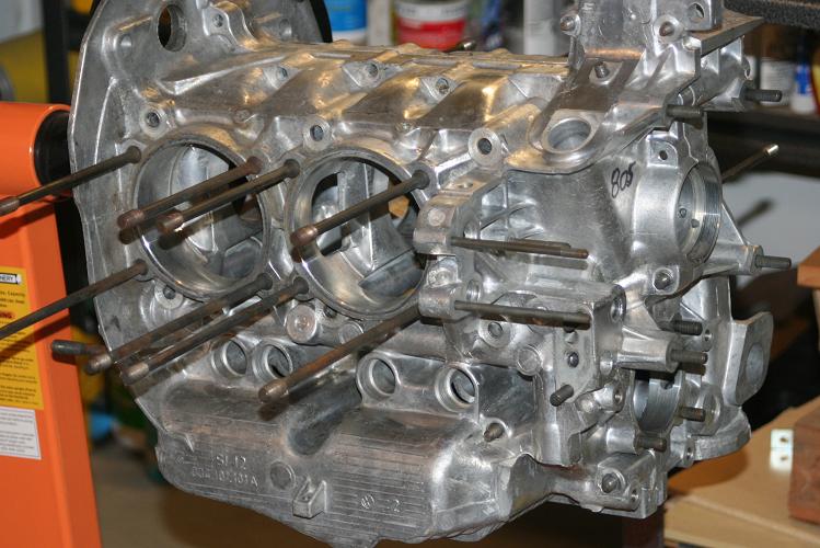
Posted by: craig downs Mar 19 2008, 12:38 AM
Looks like your on the way to have a good running engine with all the right parts.
Those are some pretty heads and the case is so clean nice work.
Posted by: PBritain Mar 19 2008, 12:49 AM
what did you use to clean the case?
looks incredible!
Posted by: MrKona Mar 19 2008, 09:11 AM
what did you use to clean the case?
looks incredible!
Thanks. I first cleaned the case at my local self-serve car wash so that I could work on it enough to pull the galley plugs. But then I took it to a local metal cleaner http://www.americanmetalcleaning.com/ Best $50 I could have spent.
They got almost all the old crud off it. I've since gone over it again with carb cleaner, Simple Green, and fresh water with a tooth brush after it came back from the machine shop. It's clean, the flash on the camera makes it look very clean.
I also had the grimy through bolts professionally cleaned, as well as the sheet metal pieces that mount under the cylinders. They were rusty, but came back clean metal, which I have since painted.
Attached thumbnail(s)
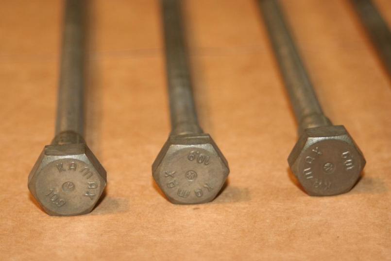
Posted by: Jake Raby Mar 19 2008, 09:15 AM
Lookin good!
I like the cleaned threads on the case fasteners. Clean threads are a necessity for proper torque values as "run on torque" will hamper the net torque the fastener sees.
An engine build is never clean enough. Surgical cleanliness and practices are mandatory!
Posted by: MrKona Mar 19 2008, 09:19 AM
Lookin good!
I like the cleaned threads on the case fasteners. Clean threads are a necessity for proper torque values as "run on torque" will hamper the net torque the fastener sees.
An engine build is never clean enough. Surgical cleanliness and practices are mandatory!
Thanks Jake! Yes, I'm trying to keep this whole assembly and my work area as clean as possible.
Posted by: Jake Raby Mar 19 2008, 09:29 AM
Excelent..
Stay away from shop rags filled with lint and rubber gloves that will hinder your ability to feel debris in the assembly lube used for the build up. I have saved myself many times by feeling "grit" in assembly lube.
Lint free towels are a must as well as serious doses of denatured alcohol or carb cleaner and compressed air.
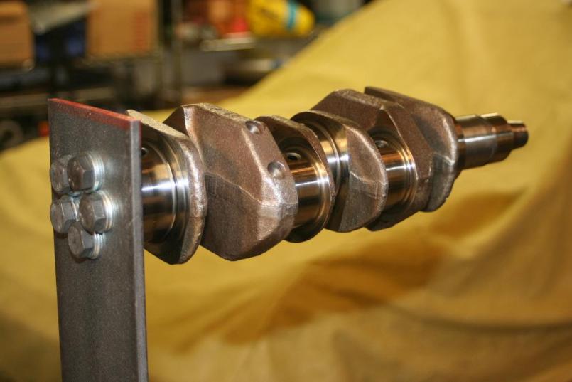
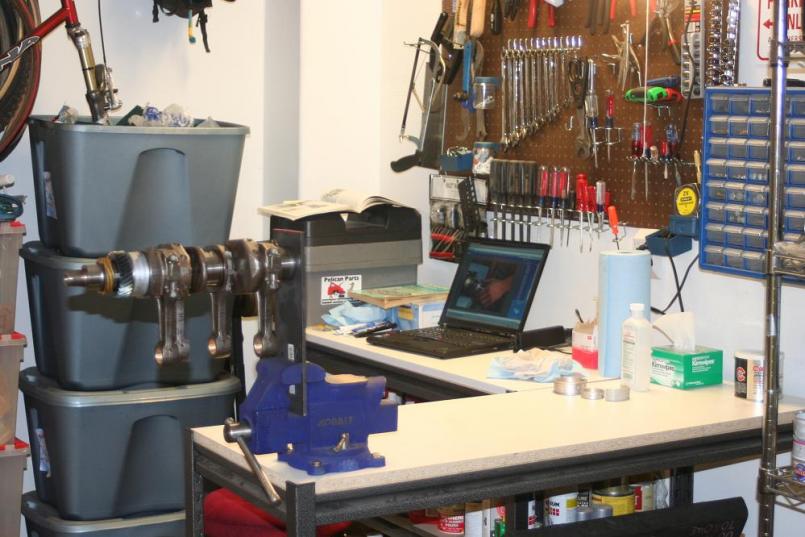
Posted by: Vacca Rabite Mar 19 2008, 10:14 AM
That crank bracket is brilliant. I wish that I had thought of it when I was playing with my crank last month.
Zach
Posted by: MrKona Mar 22 2008, 01:15 AM
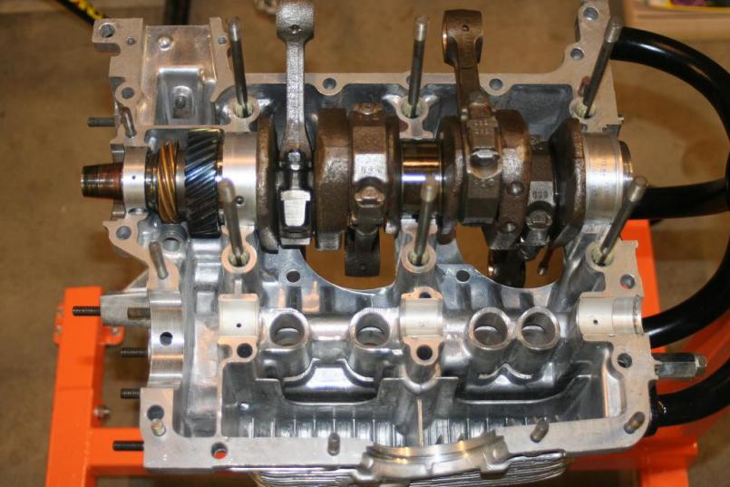
So tonight was a good night, after months of amassing and cleaning parts, I finally starting assembly! I fitted the case fasteners and plastic vibration dampeners last night, sealing the fastener heads and new washers with Permatex Ultra Black. Tonight I fastened the rods to the crank, torquing the rod nuts to a final torque of 24 ft/lb. I applied Permatex Threadlocker red to the rod bolt threads - not sure if that was necessary, but it's recommended in Wayne Dempsey's 911 engine rebuild book, so I went ahead and applied it for extra assurance. I had to stop the the other night as my socket was a little too fat to fit neatly between the rod nut and rod body. I didn't want to mangle new rod nuts. I had an extra 14mm el cheapo socket so I ground it down a hair around the perimeter and it fit fine.
Very conveniently had my laptop in the garage with Jake's video. Took it step by step, bearings into case after a final wipe down with alcohol and a lint-free wipe. Crank fell neatly into place after the bearings were lined up with the dowel pins. Made sure to run some oil into all the crank journal oil passages. Cam bearings in... and that was where I had to stop. The cam gear comes with 4.5mm hex head bolts. I have 4mm and 5mm hex drivers, but no 4.5. It was a good time to stop. Next step will be to pick up a 4.5 hex driver so that I can mount the 9550 cam onto the cam gear and install the assembly into the case.
Attached thumbnail(s)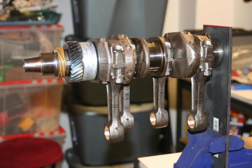
Posted by: MrKona Mar 22 2008, 01:16 AM
More...
Attached thumbnail(s)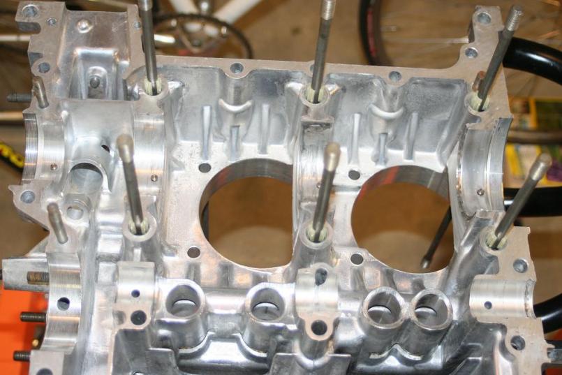
Posted by: Gint Mar 22 2008, 08:36 AM
Cool thread. Thanks for taking the time to post your progress and pics.
Posted by: MrKona Mar 23 2008, 12:34 AM
Cool thread. Thanks for taking the time to post your progress and pics.
No problem! Glad you're enjoying the thread.
Posted by: MrKona Mar 23 2008, 12:47 AM
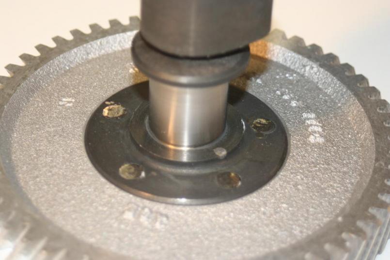
A little more progress tonight. I fastened the cam gear to the cam, applying Permatex red threadlocker to the bolts. Made sure to align the cam/gear properly with the gear notch at the 12:00 position and rear lobe at 6:00. cut and ground the exposed bolts on the reverse side, as specified in Jake's valvetrain presentation.
Placed the assembly in the case, mating up to the timing gear, locating the notch on the cam gear between the two on the timing gear.
It's a great feeling to be putting this engine together, and I'm thoroughly enjoying the pre-build research, parts assembly, and now the build. I bought Tom Wilson's book back in 1997 when I first became interested in 914's. Got my 914 back in 2004, and now, after 10+ years, it's very satisfying to finally be building an engine with my own hands.
Attached thumbnail(s)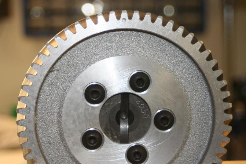
Posted by: Walter Mar 23 2008, 07:17 AM
Cool! What cam did ou end up with?
I like the allen cam bolts. Where are those from?
Cam gear seems to have been recessed as well. It almost suggests its from somebody who had given this some thought
Posted by: MrKona Mar 23 2008, 11:46 AM
Cool! What cam did ou end up with?
I like the allen cam bolts. Where are those from?
Cam gear seems to have been recessed as well. It almost suggests its from somebody who had given this some thought
Hi Walter. I ended up going with a 9550 cam and lifters from Aircooled Technology.
Posted by: MrKona Apr 3 2008, 11:54 PM
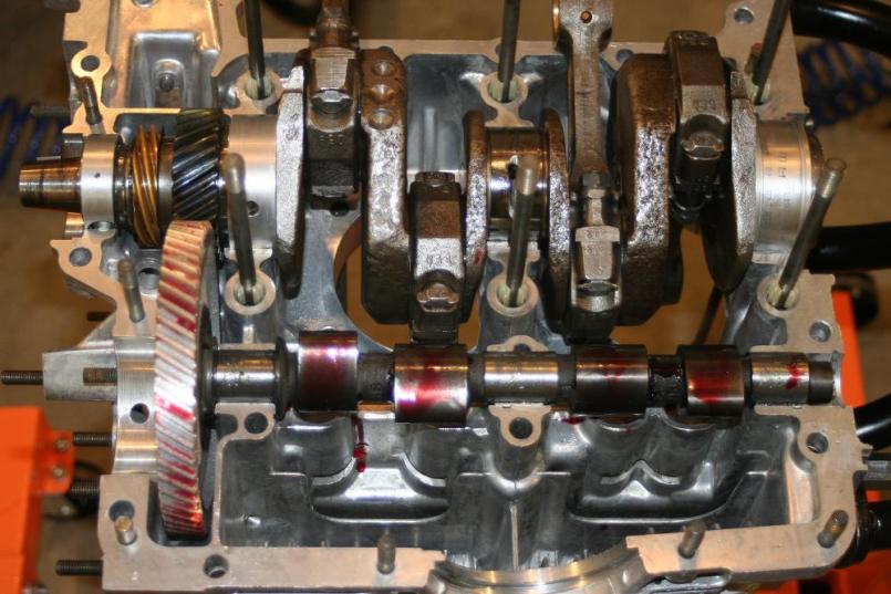
Slowly, but surely, progress marches on, and it's starting to look more like engine now. Case halves joined, sealed with Curil K2, through-bolt threads sealed with Permatex Ultra Black, crank turns smoothly with case fasteners torqued to spec.
Attached thumbnail(s)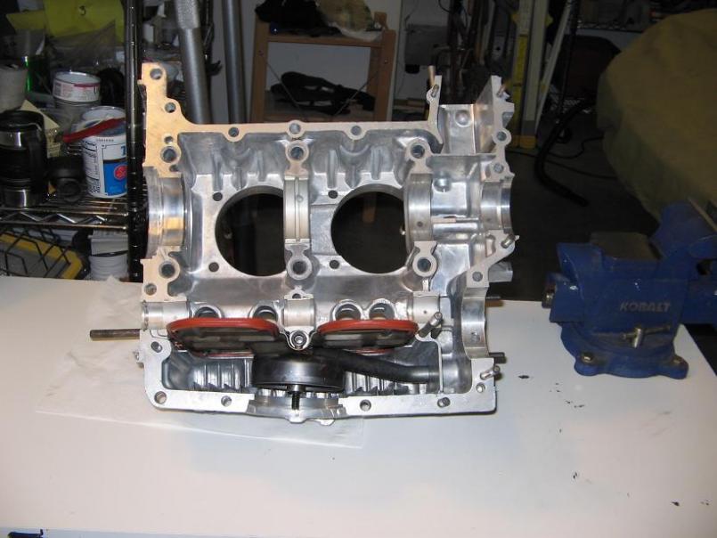
Posted by: Todd Enlund Apr 4 2008, 01:00 AM
Looking killer, dude! 
Posted by: MrKona Apr 6 2008, 01:08 AM
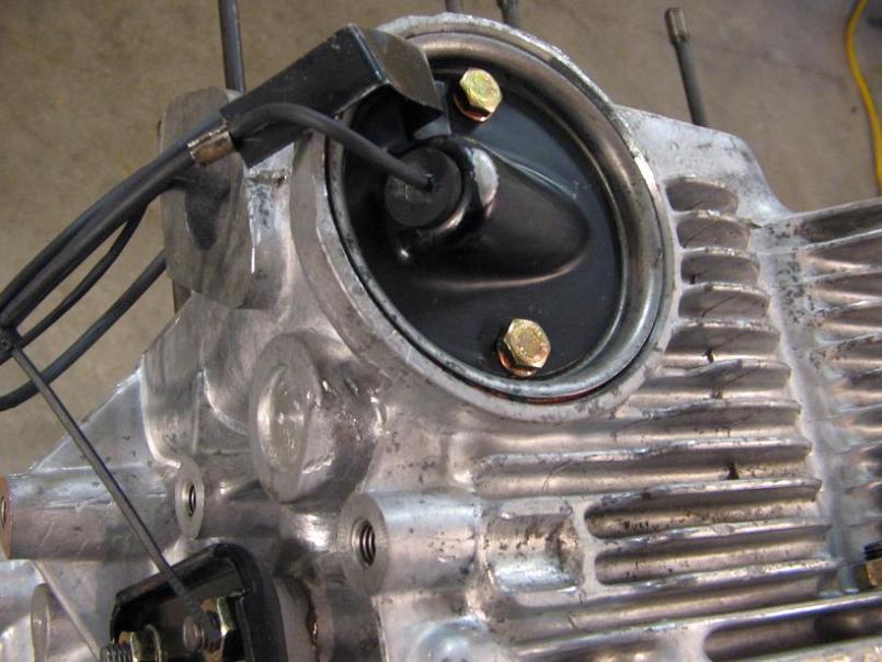
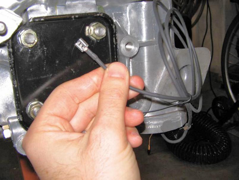
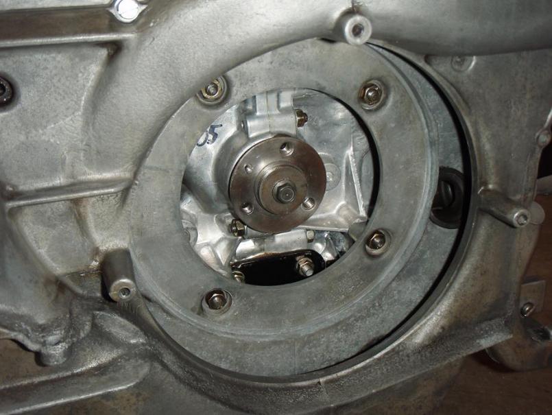
Today I installed the oil pump (modified type 1), fan hub, oil filter mount, oil strainer and cover, and taco plate. The old wire from the oil temp sender at the taco plate was in bad shape. I had some wire, heat shrink tubing, and terminals so I made a new lead, much cleaner that using the old one. I had a rubber grommet that fit the taco plate cover hole nicely, and I filled in the remaining space around the wire with some Permatex Ultra Black to seal it off.
Here's a couple shots showing the latest. The last one is a gratuitous beauty show because I just really enjoy staring at this nice clean engine. Next up is pistons and cylinders...
Attached thumbnail(s)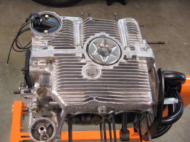
Posted by: MrKona Apr 6 2008, 01:10 AM
Beauty shots...
Attached thumbnail(s)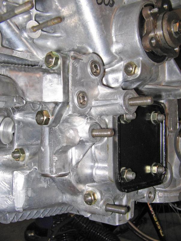
Attached image(s)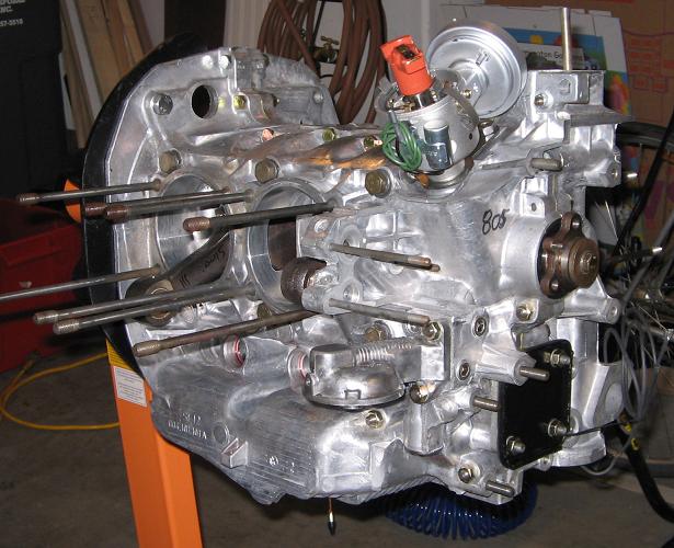
Posted by: JRust Apr 19 2008, 06:23 AM
Hard to believe that was the engine I sold you. Impressive work Bryan! Keep it up
Posted by: powdercoater Apr 19 2008, 10:25 AM
Now that you will that killer rebuild, have you considered what to do with the engine tin and fan/housing? The exhaust can also be ceramic coated to clean it up. What a nice piece, way to go.
Posted by: MrKona Apr 19 2008, 10:33 AM
Hard to believe that was the engine I sold you. Impressive work Bryan! Keep it up
Thanks Jamie, I appreciate that!
Posted by: MrKona Apr 19 2008, 10:52 AM
Now that you will that killer rebuild, have you considered what to do with the engine tin and fan/housing? The exhaust can also be ceramic coated to clean it up. What a nice piece, way to go.
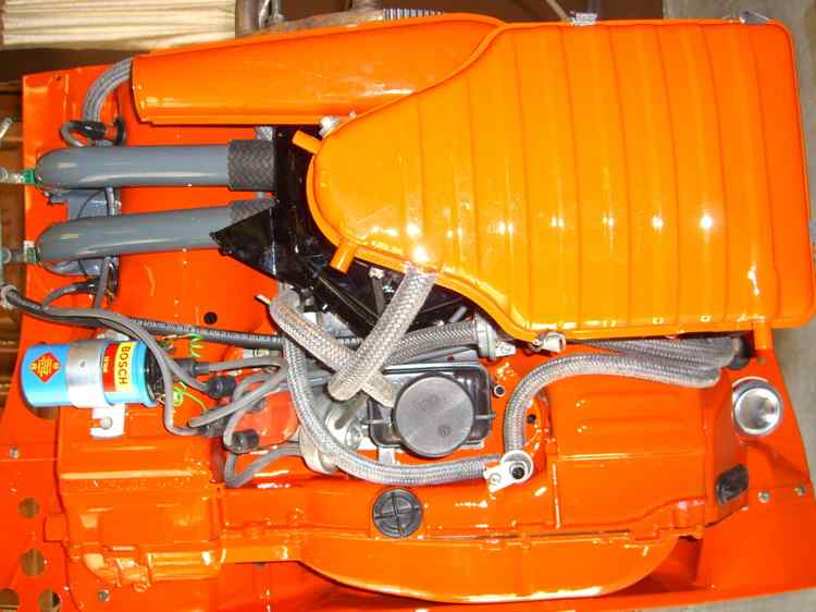
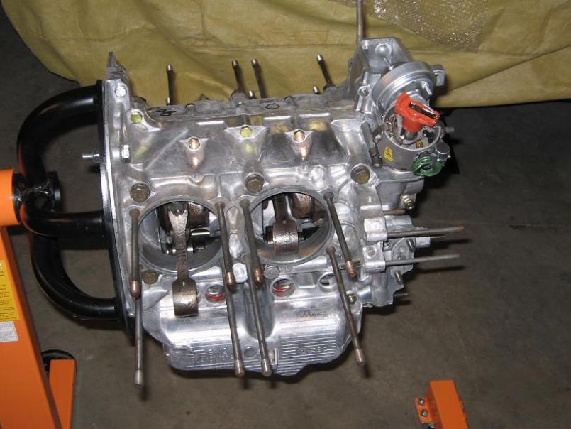
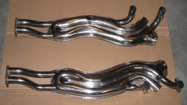
Actually... now that you mention it, I'm planning on having the tin powder coated. It's in decent shape right now (see picture from a previous engine removal and cleaning), but considering all the effort that will have gone into this engine, I want the tin to look new. I'm thinking a satin black, not too far from the stock look, not too glossy. Before I take this all to the powder coater, I need to locate the tin cylinder covers, as well as the intake tubes for a 2.0 engine, as my current engine set up is a 1.8.
I have a SS exhaust which is all polished up already (I'll post another gratuitous picture of it after I spent hours cleaning and hand polishing) but the J-tubes and exhaust elbows are rusted and look bad when paired with the SS exhaust. I was thinking of having the powder coater take care of those as well, but would ceramic coating be better for exhaust pieces? Will powder coating stand up to the high temps of the exhaust pieces? My local powder coater also does ceramic coating, I haven't yet spoken to him about this project. I also have rusted heater flapper boxes which look pretty bad, and I'm not sure how best to address those to make them look new... perhaps I need to buy them new, but I'd rather save some $$$ if they can be refinished for less than the price of new ones. At this rate, I'll be on the road by 2010.
Attached image(s)
Posted by: powdercoater Apr 19 2008, 12:41 PM
For the tin if you want to have it factory looking then the choice of a semi gloss black is the color that is normally chosen. It looks clean without too much show. Some areas of note on the fan and shroud thare are places that need to be masked for the powder coating process. Powder coating will build between .003"-.005" this is thick enough to be considered an interference to bearing and torqued mating surfaces. The fan its self was a natural cast aluminum in most cases, but it is common to either coat them black or silver. Ther are some cool finishes that can replicate metals in semi gloss and matte finishes.
The ceramic coating if done correctly is the way to go, don't waste your time with the rattle can stuff. The correct look is to have them done in gray 1300F rated coating, gray looks killer if again you want a factory apperance. Other availabe colors are silver matte and polished, black matte or semi gloss, blue (nasty), white, copper and red (not too red). There are also coatings that will also go to 2000F but these are textured black, gray or blue only.
Scott
Posted by: MrKona Apr 19 2008, 01:50 PM
For the tin if you want to have it factory looking then the choice of a semi gloss black is the color that is normally chosen. It looks clean without too much show. Some areas of note on the fan and shroud thare are places that need to be masked for the powder coating process. Powder coating will build between .003"-.005" this is thick enough to be considered an interference to bearing and torqued mating surfaces. The fan its self was a natural cast aluminum in most cases, but it is common to either coat them black or silver. Ther are some cool finishes that can replicate metals in semi gloss and matte finishes.
The ceramic coating if done correctly is the way to go, don't waste your time with the rattle can stuff. The correct look is to have them done in gray 1300F rated coating, gray looks killer if again you want a factory apperance. Other availabe colors are silver matte and polished, black matte or semi gloss, blue (nasty), white, copper and red (not too red). There are also coatings that will also go to 2000F but these are textured black, gray or blue only.
Scott
Scott,
Thanks for the advice, this is really helpful. I'm imaging pretty close to what you describe... Satin or semi-gloss black for the tin, natural aluminum look for the fan and shroud, and probably gray for the stock exhaust pieces. I want this car to maintain a "classic" look.
Posted by: MrKona May 23 2008, 06:32 PM
It's been just over a month since I've posted. Unfortunately, progress was halted by a combination of school, work, and some family medical issues. It's time to get started again...
I measured deck height on all four cylinders. I actually made a torque plate so that I could torque the cylinders to spec, and then measure deck height with a dial indicator. I tried that, but ended up giving up and resorting to the method used by Competition Engineering, and also used by Wayne Dempsey in his 911 rebuild book. http://www.competitioneng.com/DeckHeight.htm
This method relies on using large diameter acid core solder. I cut two pieces per piston, removed the acid core from each piece with a small drill bit and a paper clip. At that point, I placed two pieces on the top of each piston, a little Curil-T to hold each piece in place on the piston head. Then torqued the head to spec. At that point, it takes a half turn of the fan to bring the pistons up to the cylinder head, compressing the solder. Remove the head, take the smallest measurement of each compressed solder piece. Average the two measurements for each piston to calculate deck height.
I used a .010" and a .040" cylinder to case spacer for a total of .050" on each cylinder. This gave me the following deck deck heights:
Cylinder 1: .053"
Cylinder 2: .052"
Cylinder 3: .050"
Cylinder 4: .051"
Combustion Chamber volume = 57.6cc
Euro spec Mahle piston dish = 3cc
Stroke = 71mm
Bore = 94mm
Using the CR calculator on aircooled.net this gives me a calculated CR:
Cylinder 1: 8.0/1
Cylinder 2: 8.0/1
Cylinder 3: 8.1/1
Cylinder 4: 8.0/1
Pretty straight forward, and I'm happy with this combo that I've achieved stock Euro-spec CR.
Attached thumbnail(s)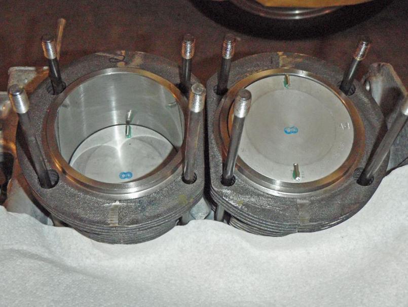
Attached image(s)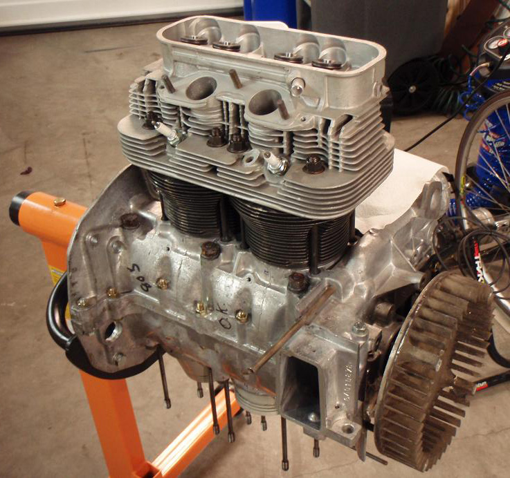
Posted by: MrKona May 23 2008, 06:34 PM
More...
Attached thumbnail(s)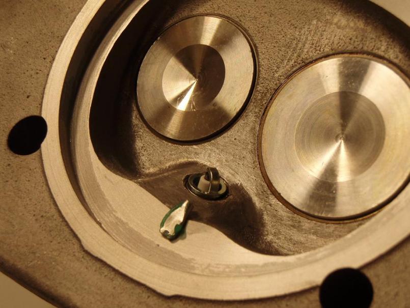
Attached image(s)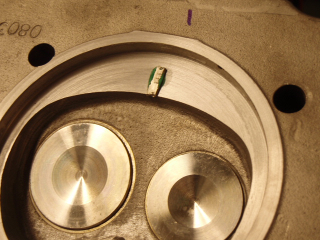
Posted by: MrKona May 23 2008, 06:34 PM
More...
Attached thumbnail(s)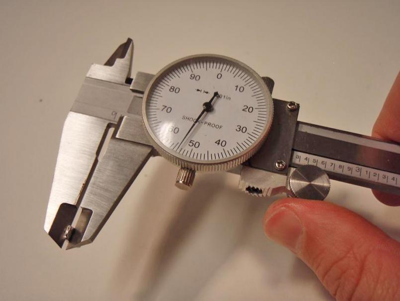
Posted by: rhodyguy May 23 2008, 10:22 PM
bryan, powdercoating for the duct pieces, warm air elbows, and j-tubes works swell, seals real tight. i coated the 2 lower wrm air guide that connect the hes to the case too. due to the pivots and the valve shaft, paint is the way to go on the valves. your hes look swell. is that the new tin on the case? you're pretty close.
k
Posted by: MrKona May 23 2008, 11:11 PM
bryan, powdercoating for the duct pieces, warm air elbows, and j-tubes works swell, seals real tight. i coated the 2 lower wrm air guide that connect the hes to the case too. due to the pivots and the valve shaft, paint is the way to go on the valves. your hes look swell. is that the new tin on the case? you're pretty close.
k
Hi Kevin,
Thanks for the tip regarding paint on the valves. Both of mine are pretty rusty right now, so I'll have to see if they can be blasted clean, but inside and out. The tin in the picture is actually my current tin for the 1.8, just cleaned up for that picture after my last engine drop. I worked pretty hard on those heat exchangers. I wish one of them wasn't dented. At least you can't see it when they're mounted on the car, but it still gets to me when I look at that picture.

I haven't even touched the tin I got from you yet. Once I get a little further on this engine, I'll be bringing the tin, runners, fan, and exhaust pieces to the local powder coater. It's going to look so nice.

I may even have him coat the fan shroud if there is a "natural" looking color availabe in powder coat that looks appropriate.
- Bryan
Posted by: Jake Raby May 24 2008, 06:19 AM
Even I am impressed with how sterile the engine is, thats the key to a successful build and it shows a lot of pride in your work. This one will run really well!
Posted by: MrKona May 24 2008, 12:11 PM
Even I am impressed with how sterile the engine is, thats the key to a successful build and it shows a lot of pride in your work. This one will run really well!
Jake, Thank you. I take that as a huge compliment.
Posted by: MrKona May 26 2008, 01:06 AM
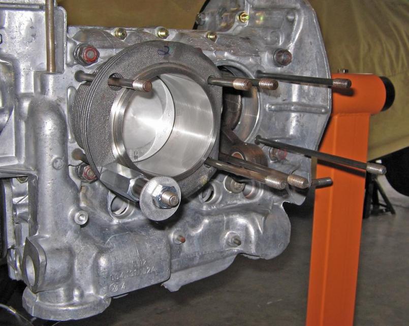
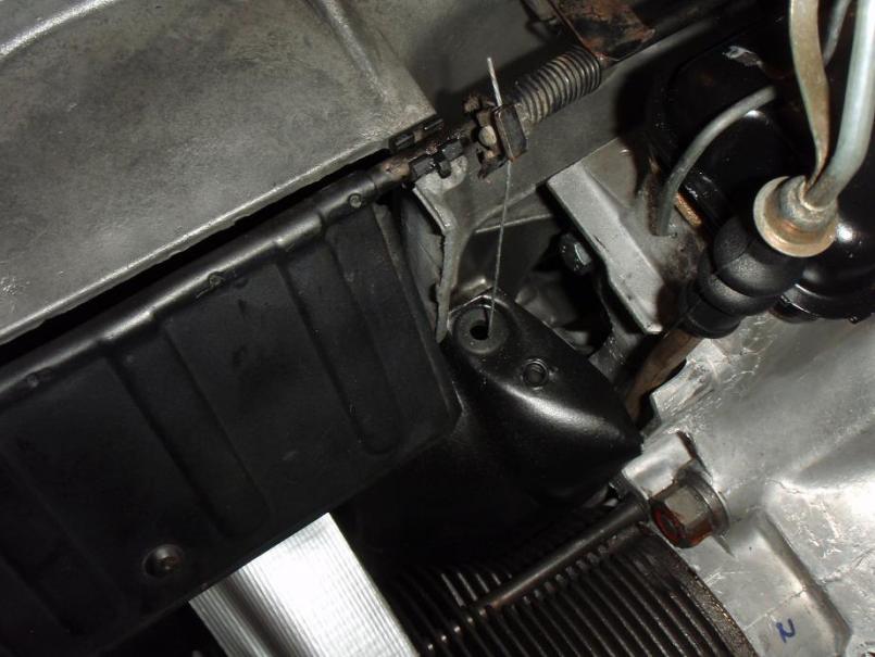
A little setback tonight, due to what looks design flaw with my engine stand mount. Although before I can say for sure, please take a look at these pictures and tell me if I'm missing something here...
I installed p/c #4 first so that I could drive the piston pin toward the fan side of the engine, due to the oil cooler mount. Next is #3. However, as I slide the p/c assembly on, the piston pin hits my engine stand. 
I looked at pictures of other stands, and I notice that they have an indentation cut out at that spot, for what I assume is the #3 piston pin. They are thicker, from the looks of it to maintain strength despite the cut-out indentation.
I picked this stand up on Ebay from a local USA made company with really good feedback. I have a hard time believing that I'm the first person to notice this "flaw". Am I just not seeing the obvious, or do I really need to remove this engine from the stand just to install the #3 piston pin? 
Attached thumbnail(s)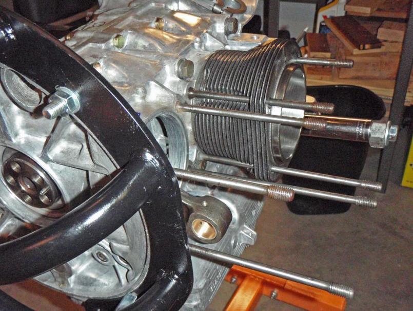
Attached image(s)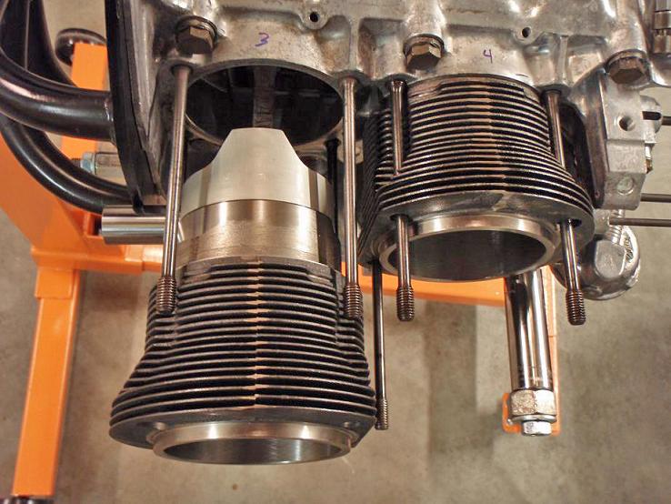
Posted by: MrKona May 27 2008, 12:20 AM
Problem solved... I had to remove the engine from the stand and cut away that section. After cutting, it was easy to install the piston pin. I also noticed after the cylinder was installed, that one of the cylinder fins would not have cleared the stand without cutting it.
Attached image(s)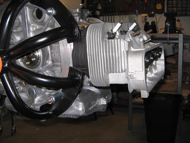
Posted by: MrKona May 27 2008, 12:27 AM
Tonight I experienced the thrill of victory, which turned to the agony of defeat in about 3 seconds after I realized a mistake I made. Today I installed the pistons/cylinders, heads, cylinder head sheet metal pieces, and push rod tubes. I was looking forward to posting pictures of my progress. Figured the icing on the cake tonight would be to install the cylinder head temp sensor.
This is when the shock hit me. I installed the heads on the wrong side. The cylinder head temp threaded hole is on the driver side instead of the passenger side! This was a first-timer mistake that I will never make again. Unfortunately, I'm traveling Tuesday - Friday this week for work, so won't get a chance to right this wrong until the weekend. If I didn't have to get up early tomorrow morning, I'd be working on this late into the night. I'll be frustrated with this until I can make it right... 
I'll post more pictures after I fix this.
Posted by: jmill May 27 2008, 02:04 PM
Great thread. Thanks for sharing. I'm planning my own rebuild and your pics and experiences will really help me out. I have to say that is one clean engine. Fantastic work.
Could you have slid the #3 piston pin in from the other side before installing #4?
Posted by: MrKona May 28 2008, 12:07 AM
Great thread. Thanks for sharing. I'm planning my own rebuild and your pics and experiences will really help me out. I have to say that is one clean engine. Fantastic work.
Could you have slid the #3 piston pin in from the other side before installing #4?
Thanks very much. I'm keeping this whole assembly as clean as possible. A lot of carb cleaner, alcohol, lint-free wipes, and compressed air to keep pieces clean and dust free. I also cover the engine when I'm not working on it to keep dust off.
I wrote about my mistake with the cylinder heads especially so that someone else could avoid the same mistake.
Regarding the pistons, you have to install the piston pin of cylinder #4 from the inside of the piston, as the oil cooler mount portion of the case prevents you from accessing it from the outside (fan side) of the case. If you install piston/cylinder #3 first, there is no way to install the #4 pin from the inside (as #3 cylinder will be in the way).
Posted by: Jake Raby May 28 2008, 06:23 AM
And I do go over that in detail, in my TIV engine rebuild video.
Posted by: purple May 28 2008, 10:21 AM
Nice thread....has me really wanting to build my own engine. I know jake will help me with that once I've got the money saved
Posted by: 6freak May 29 2008, 01:27 PM
That crank bracket is brilliant. I wish that I had thought of it when I was playing with my crank last month.
Zach
I LOVE PLAY`N WITH MY CRANK TOO


Posted by: MrKona May 30 2008, 12:07 AM
Nice thread....has me really wanting to build my own engine. I know jake will help me with that once I've got the money saved
I've been wanting to build an engine for probably about 10 years now... and I must say, now that the time has come, this has been one of the most satisfying things I have done in a long time...
Posted by: MrKona May 30 2008, 12:12 AM
And I do go over that in detail, in my TIV engine rebuild video.
and that's exactly where I learned it.
Posted by: Phoenix914 May 30 2008, 06:24 AM
Your engine looks fantastic. Please keep us updated with commentary and pictures. I'm planning to rebuild my 2056 this summer and need all the inspiration I can get!
Posted by: MrKona Jun 1 2008, 01:47 AM
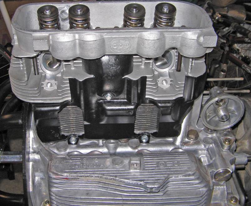
I have got to spend a few hours on the engine today, and was able to "right" my "wrong" from last week, when I installed the cylinder heads on the wrong sides. I feel much better now... So here are some pictures from last week and today.
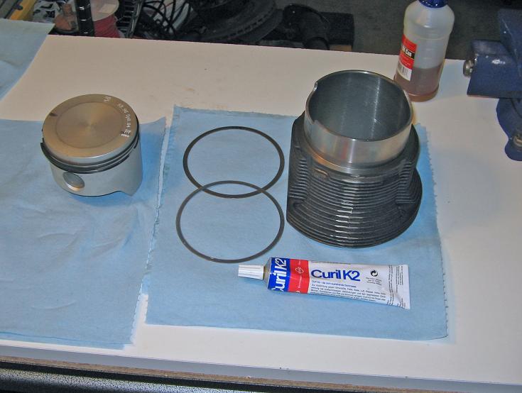
I had removed the piston rings before I mocked up the pistons, cylinders and cylinder heads for deck height. Prior to reinstalling them, I cleaned up the pistons and cylinders with a combo of carb cleaner, alcohol, lint free wipes, and compressed air. As everyone says, don't assume that the parts are clean from the factory. I got a lot of black residue off the cylinder walls. After I had reinstalled the rings, I installed the pistons in the cylinders. Sorry, no picture of the pistons going into the cylinders, but I did it as Jake describes in his video. Make sure not to push the piston in too hard when installing it in the cylinders. It took me the first piston to get the technique down for the ring compressor. Once I figured that out, the pistons went in with just a light tap on the top of the piston with the end of a plastic hammer handle. Although the pictures show the cylinder with the beveled edge up, I installed the piston into the other end of the cylinder.
I used two spacers at the base of each cylinder and put a thin coating of Curil K2 between each spacer and at the base of each cylinder.
Attached image(s)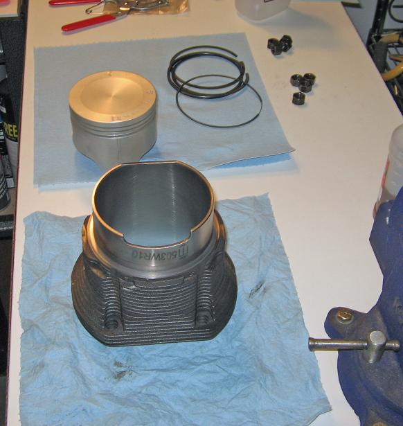
Posted by: MrKona Jun 1 2008, 01:54 AM
And on went the cylinders. It was easy to install the #3 piston pin since I had cut part of my engine stand mount away. Just make sure as you install the pistons that you don't pull back on the cylinders and expose the rings. That would mean back to the bench to reinstall the pistons with the ring compressor.
Attached thumbnail(s)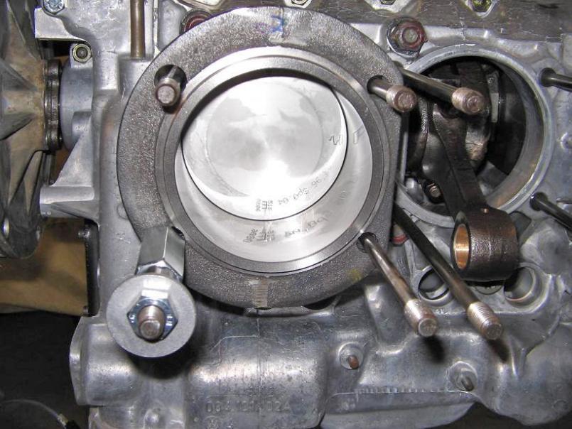
Posted by: MrKona Jun 1 2008, 01:55 AM
Pistons/Cylinders...
Attached thumbnail(s)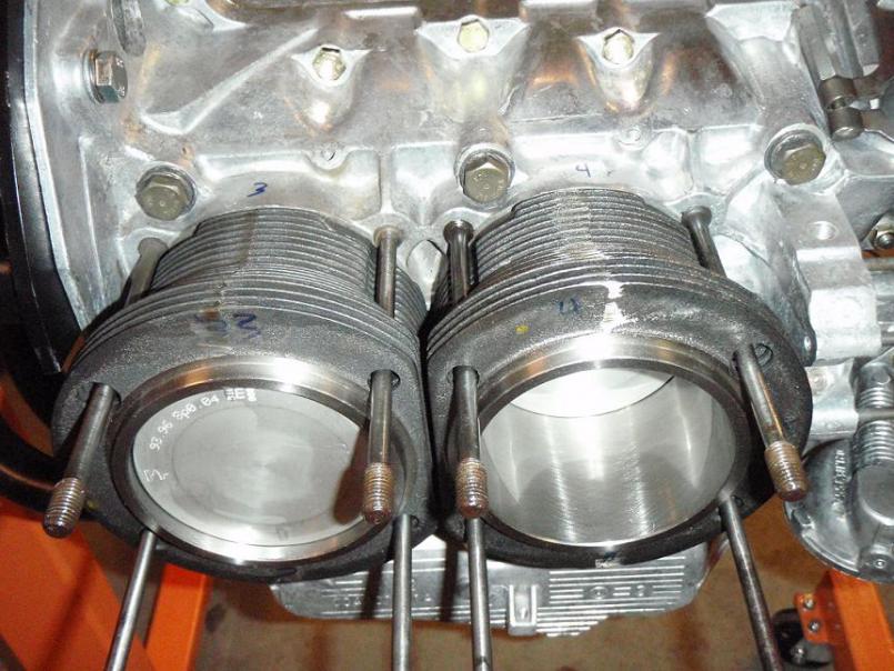
Attached image(s)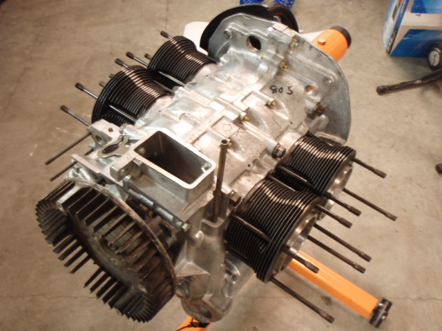
Posted by: MrKona Jun 1 2008, 02:06 AM
Next up was the installation of the cylinder heads, making damn sure that the head with the cylinder head temp sensor threaded hole is on the passenger side...
I torqued the heads in a criss-cross pattern, as illustrated on page 135 of Tom Wilson's book. I also followed his advice for the torquing of both heads:
1. Head one to 15 ft/lb, then head two to 15 ft/lb.
2. Head one to 20 ft/lb, then head two to 23 ft/lb.
3. Head one to 23 ft/lb, retorque head two to 23 ft/lb.
4. Wait a couple minutes retorque both heads to 23 ft/lb.
The next thing to go on after the heads are the under-cylinder tins. These need to go on before the pushrod tubes. I had these chemically cleaned at the metal cleaner when I had my case done. They came back nice and clean, but a little rough. I primed and painted them. I'm sure it will all burn off the first time I drive the car, but at least it looks nice during assembly... If I had been planning this better, I would have had them professionally coated and waiting for installation.
I kept a paper towel tucked under the cylinder tin as I installed the fasteners. Last thing I wanted was to drop one and have it fall into the case.
Attached thumbnail(s)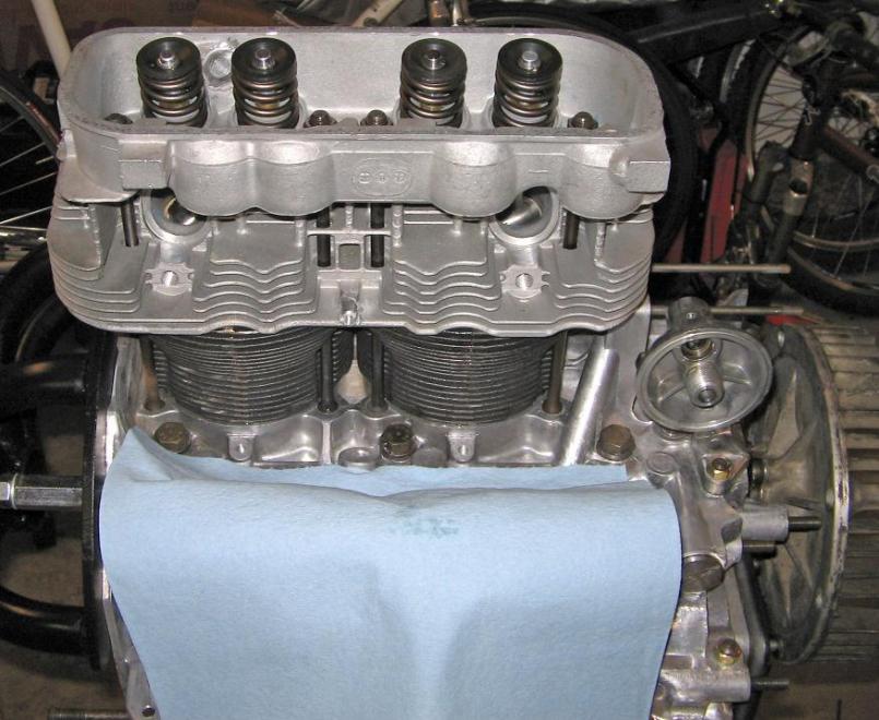
Posted by: MrKona Jun 1 2008, 02:12 AM
Next was the pushrod tube installation. As everyone advocates, I used clean motor oil and nothing else on the pushrod seals. They went in fairly easily. There's no way I could install the tubes with my hands in the cramped space, so I carefully used large pliers. I cut apart a vacuum cleaner rubber belt and placed a piece of it under the plier's jaws so as not to damage the tube, and also to get a better grip on the tube. Just make sure the outer tube is clean, so you don't have to squeeze too tightly to get a good grip. Twist and push, and they sank right into their recess. I made sure to put a couple drops of oil in the case recesses to prevent damaging a seal.
Attached thumbnail(s)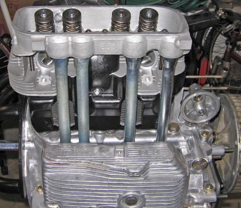
Attached image(s)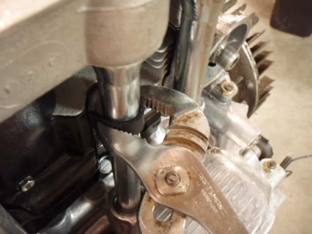
Posted by: MrKona Jun 1 2008, 02:16 AM
And that's all for tonight!
Attached thumbnail(s)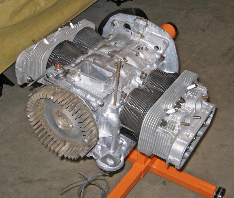
Attached image(s)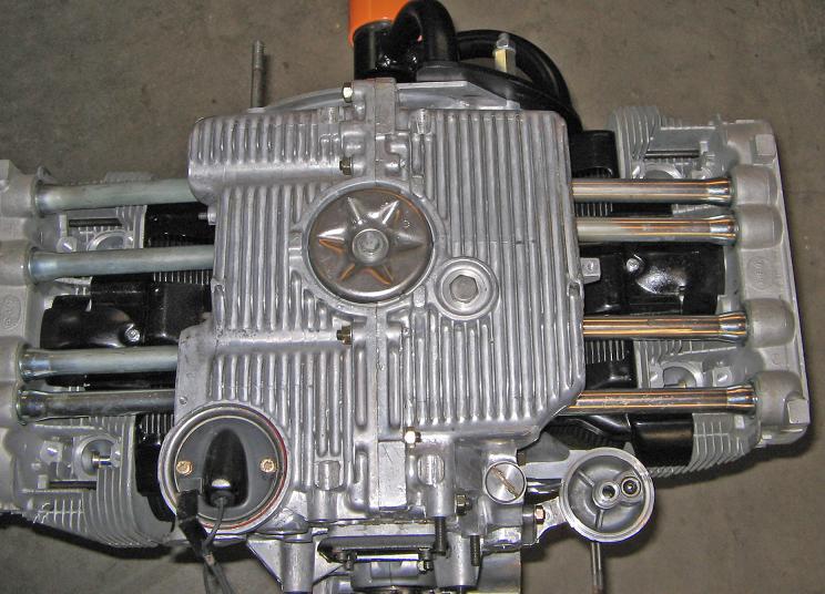
Posted by: SGB Jun 1 2008, 10:37 PM
looks great!
Posted by: MrKona Aug 4 2008, 02:03 AM
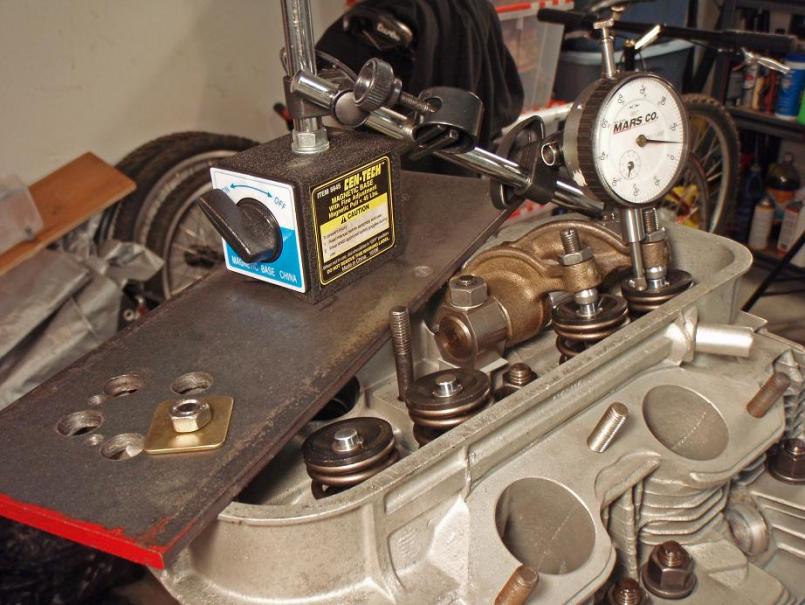
It's been awhile since I posted any progress. By no means have I lost interest in this project. Just some delays due to competing priorities... sound familiar? The engine has been sitting under plastic in the garage, waiting for me to work on it again. I set up the valvetrain geometry this weekend. I've read Jakes article many times, and searched on this site for some great information. I used an adjustable pushrod to calculate all the pushrod lengths for each valve, and have cut four. I started getting a little fatigued earlier tonight so I figured it was time to call it a night.
A couple details:
Solid spacers and swivel head adjusters. I sanded down some of the adjusters with very fine sand paper as some of the rockers fit pretty tight when first mocked the assemblies on the case. I've got them so they rock smoothly with no side to side play.
Steel pushrods. I cut them with a small pipe cutter and finished off with a grinder, deburred with a small file. Blew them clean with carb cleaner and compressed air. I had two old lifters that I used to hold the ends while I tapped in the pushrod tip.
My set up, as you can see is just a steel plate (the piece I used as a crank holder earlier in the build). Worked great to mount the magnetic dial indicator stand.
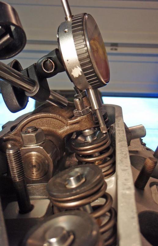
All measurements at full lift are within +/- 5% lift specs for the 9550 cam. At half lift, the valves and adjusters are about as straight as I can possibly see: Assemble, measure, disassemble, adjust, reassemble, repeat...
Lot's of fun!
Here's a couple random pictures from the process:
Attached thumbnail(s)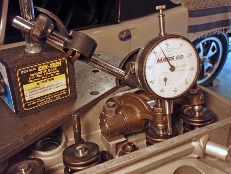
Posted by: MrKona Aug 4 2008, 02:05 AM
More...
Attached thumbnail(s)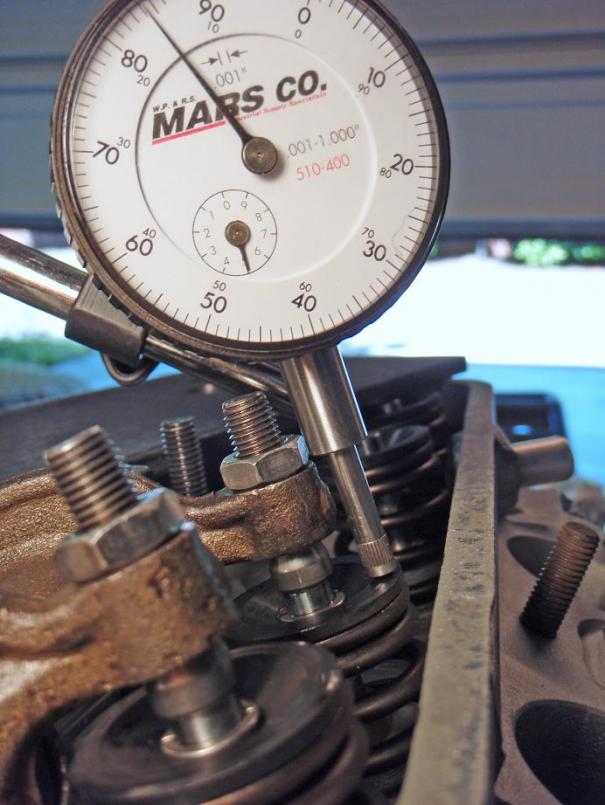
Attached image(s)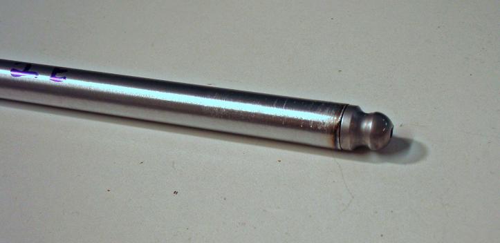
Posted by: MrKona Aug 4 2008, 02:06 AM
Last ones.
Attached thumbnail(s)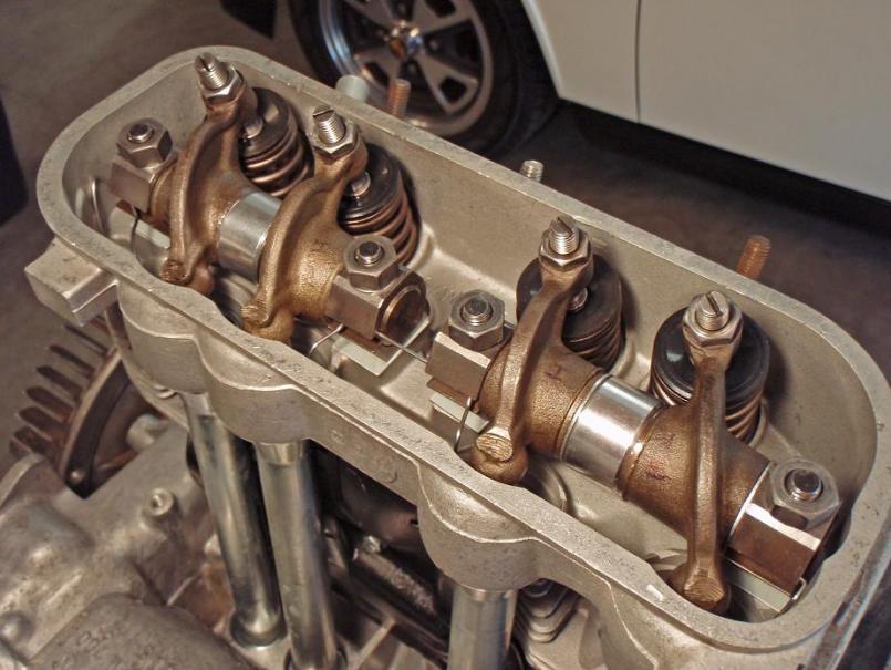
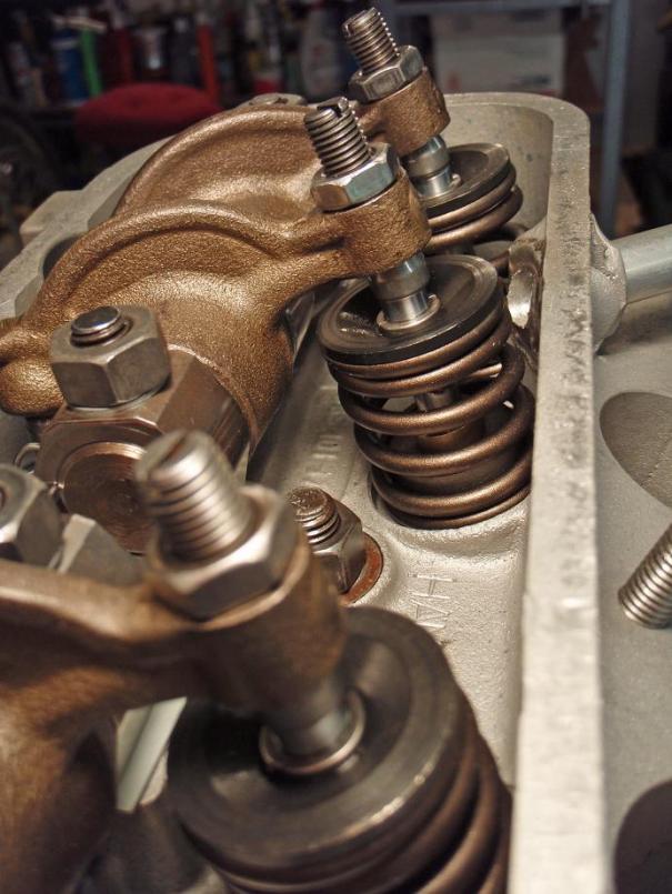
Posted by: MrKona Aug 6 2008, 08:34 PM
Valves installed and adjusted. I've come as far as I can without dropping the current engine and transferring some parts. The next few weeks will undoubtedly be spent working out some rich running fuel injection issues with the current engine. I want to get all that sorted out before installing the new engine. I'm going to have the tins and runners powder coated to look factory fresh. I also picked up some new engine compartment rubbers seals from Mark at 914rubber.com. Thanks Mark.
I have a question regarding the 1.8 fan and distributor I'll be taking off my 1.8 engine. The fan that came with this engine has a broken fin. I was originally thinking that I would find another 2.0 fan to replace it.
But thinking about it more, should I actually keep the 1.8 fan and distributor from the current engine together, rather than mixing a 2.0 fan and a 1.8 distributor? I believe the timing marks are different on the 1.8 fans (timing mark at 7.5 degrees BTDC on the 1.8 fan). Do the marks on the 1.8 fan specifically correlate to the notch on the 1.8 distributor?
Attached thumbnail(s)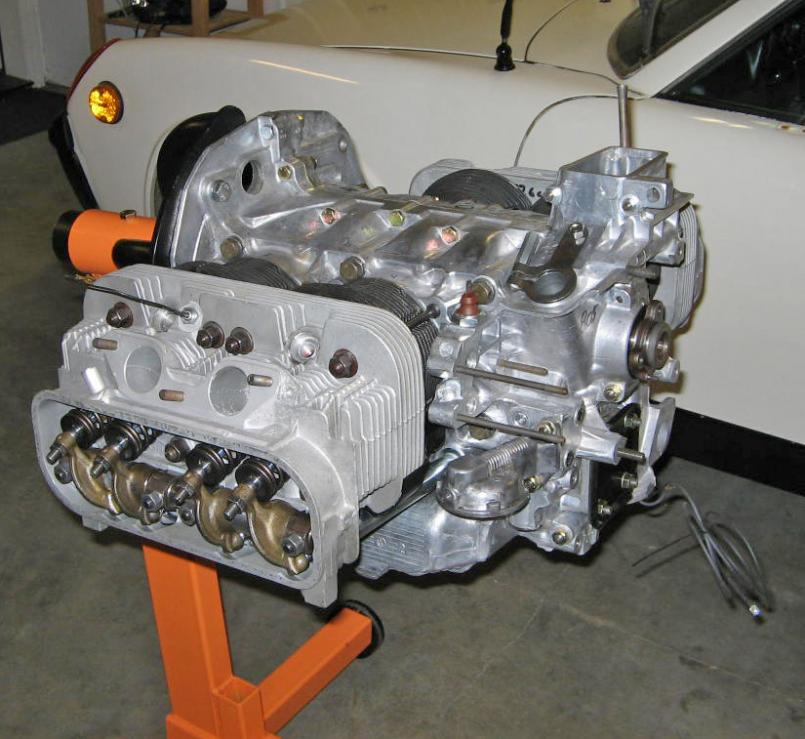
Posted by: Rav914 Aug 6 2008, 09:38 PM
Great thread. I've been following closely as I'm rebuilding my 1.7 into a 1.9. Will try to emulate your cleanliness.
Sorry, I don't know the answer to your fan question.
Posted by: MrKona Feb 7 2009, 01:27 AM
Gotta keep this thread alive... Just a tiny bit of progress tonight. New rubber engine mounts, and freshly blasted and repainted case mounts. Also new mount to case bolts. I like looking at the before and after photos.
Attached thumbnail(s)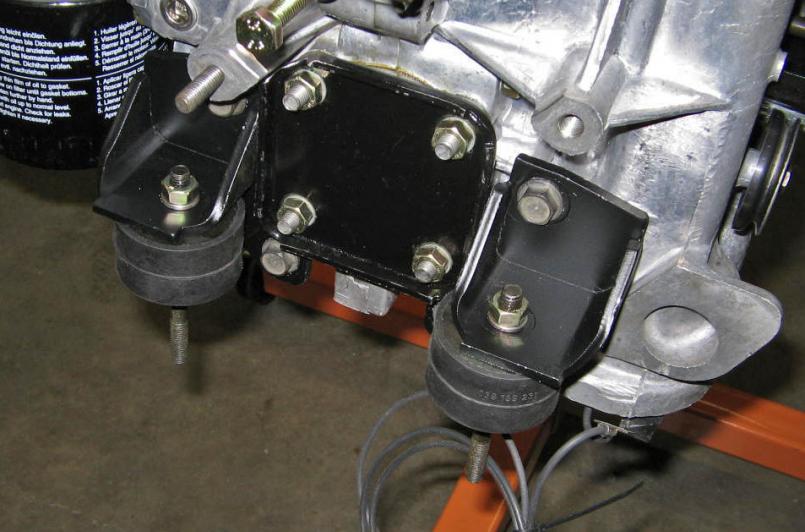
Attached image(s)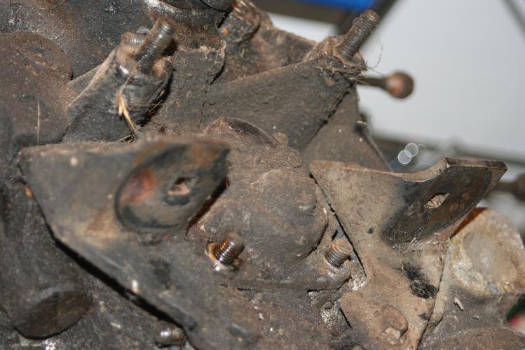
Posted by: MrKona Feb 7 2009, 01:33 AM
Also blasted and painted the thermostat mount and reinstalled the thermostat. Since I built my blast cabinet, I find myself looking around my garage for things to blast clean.
I had repaired this thermostat awhile back by injecting 99% alcohol and brazing a leak on the top. It's now back in spec for expansion and temp.
Attached thumbnail(s)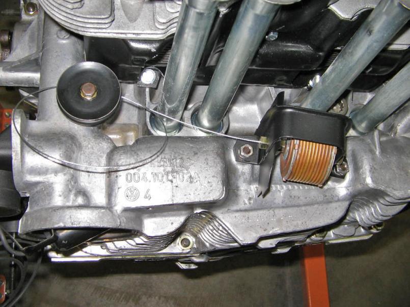
Posted by: type47 Feb 7 2009, 06:33 AM
i enjoy reading your thread of the build up and as i read it, went back to my own engine build up. you put in the pushrod tubes but didn't mention (or i read too fast) that you put in the lifters so i "hey, what about the lifters!" to myself of course you had to install them before the valve train geometry steps. your thread is a great inspiration and a great example of how things should be done. you could turn this into a "how to" DVD! keep us posted.
Posted by: MrKona Feb 7 2009, 06:27 PM
i enjoy reading your thread of the build up and as i read it, went back to my own engine build up. you put in the pushrod tubes but didn't mention (or i read too fast) that you put in the lifters so i "hey, what about the lifters!" to myself of course you had to install them before the valve train geometry steps. your thread is a great inspiration and a great example of how things should be done. you could turn this into a "how to" DVD! keep us posted.
Good point! Yes, you must install the lifters before you install the push rod tubes. The lifters won't fit through the tubes.
I'm glad you're enjoying the thread, I take that as a compliment.
Posted by: FourBlades Feb 7 2009, 10:12 PM
Wow, your engine looks great.
Your photos are so clear and focused. So much better than most books that
are supposed to teach you about engines. I almost think Hanes found the
grungiest possible car and then took the worst possible pictures.
How are you lighting the photos? Are you using any flash?
Can you show how to set the valve clearance?
John
Posted by: MrKona Dec 27 2009, 08:01 PM
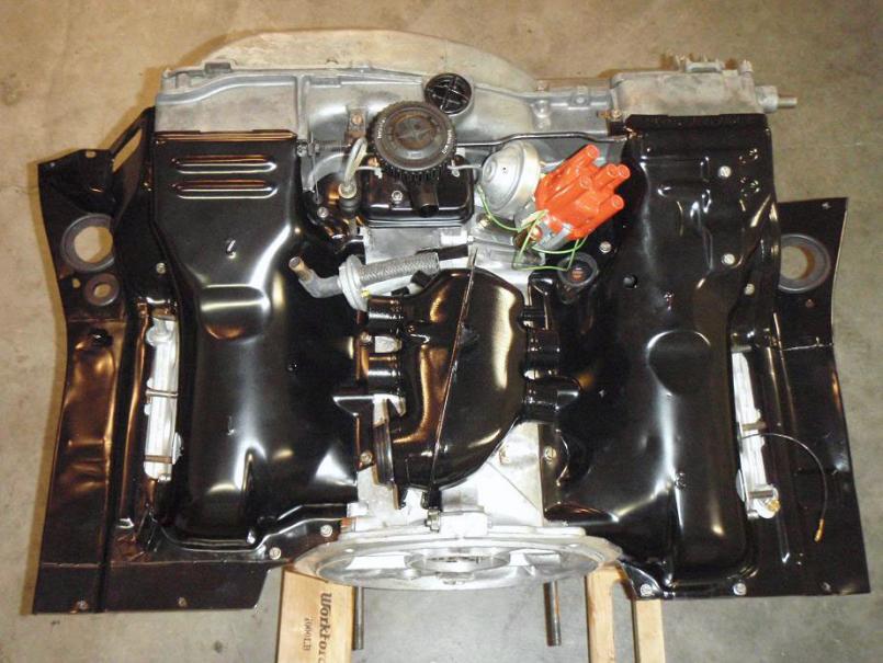
The engine is off the stand and tin and FI components are being added. I had the top tins powder coated. All the rest I painted with high temp paint.
Front side tins went on first.
Attached thumbnail(s)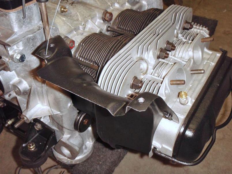
Posted by: MrKona Dec 27 2009, 08:03 PM
Then the fan shroud and fan.
You may want to temporarily tape the front passenger tin in place. There's nothing holding it in place until the top tins go on. It fell off after I put the shroud on. It found its way off, but I couldn't get it back into place without removing the shroud.
Attached thumbnail(s)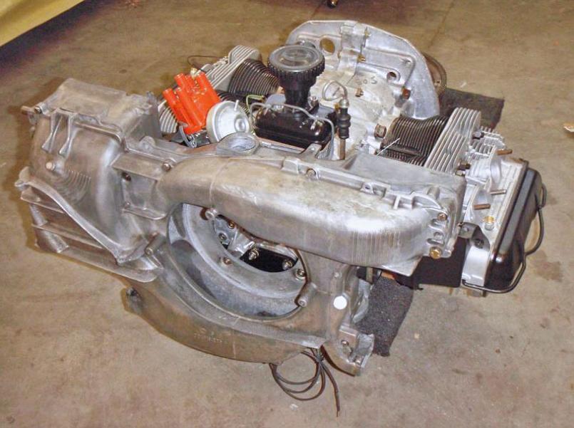
Posted by: MrKona Dec 27 2009, 08:11 PM
Then I attached the cooling flaps and thermostat cable. By the way, Ace Hardware has a really good selection of rubber grommets. I found one for the thermostat cable hole that fit great.
Attached thumbnail(s)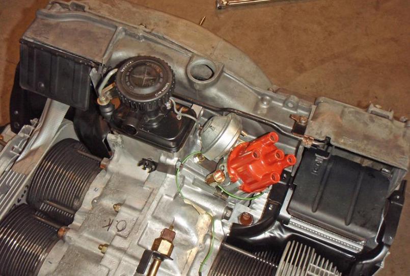
Posted by: MrKona Dec 27 2009, 08:16 PM
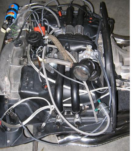
And then the top tins! I had to remove the distributor to place the right side tin.
Also started adding some FI components. My plan is to use the original L-jet components, just adding a set of 2.0 intake tubes which are drilled for the 3-stud cylinder heads...
Attached thumbnail(s)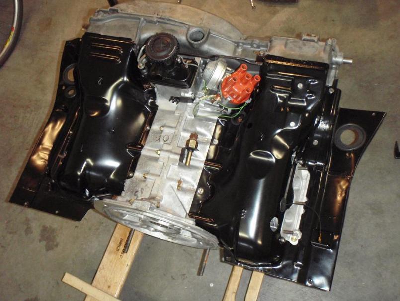
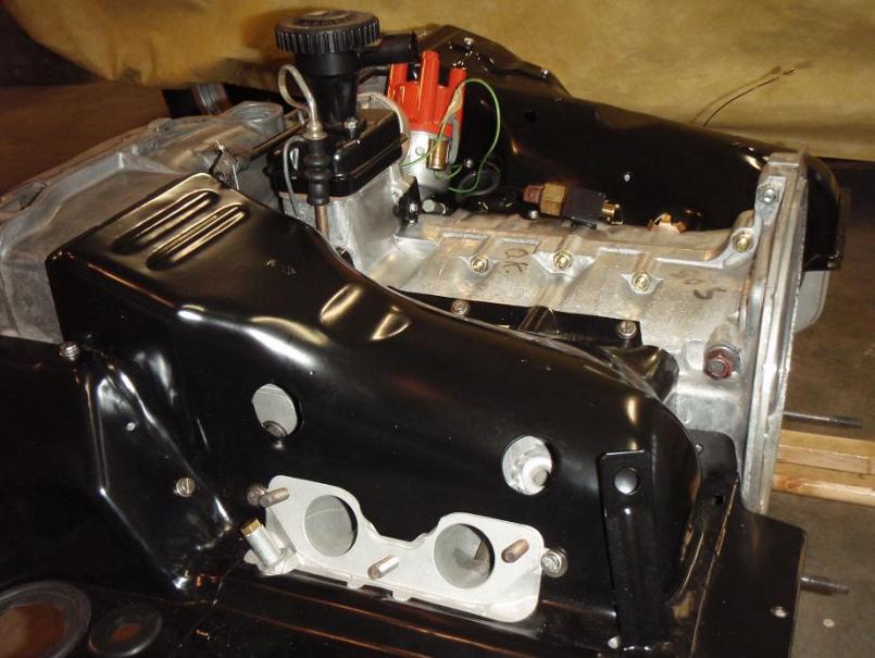
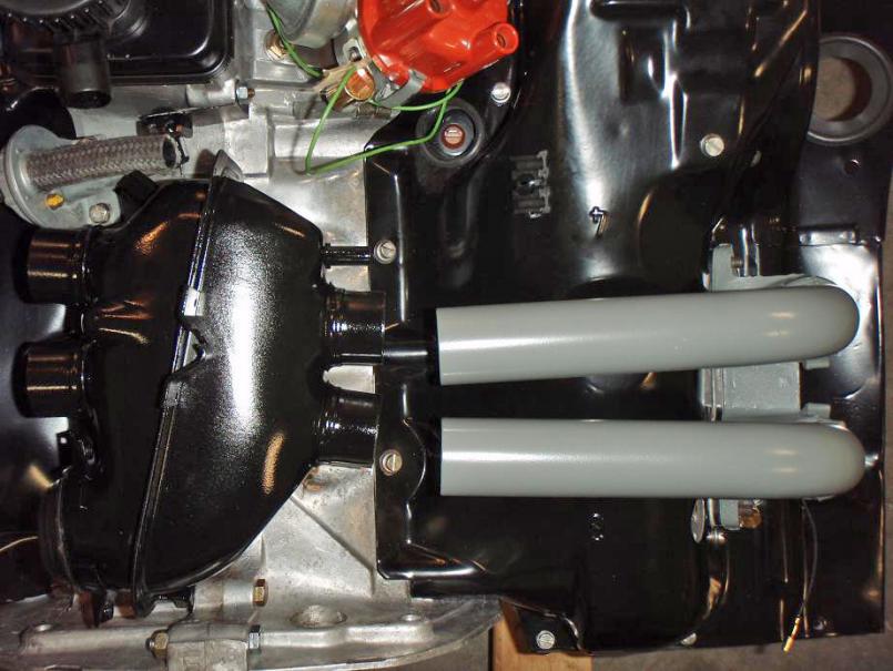
Posted by: MrKona Dec 27 2009, 08:19 PM
And this is where my momentum stopped... I acquired a set of 2.0 3-stud intake tubes. Had them cleaned, then I painted them in gray similar to the factory tubes to make them all pretty...
Attached thumbnail(s)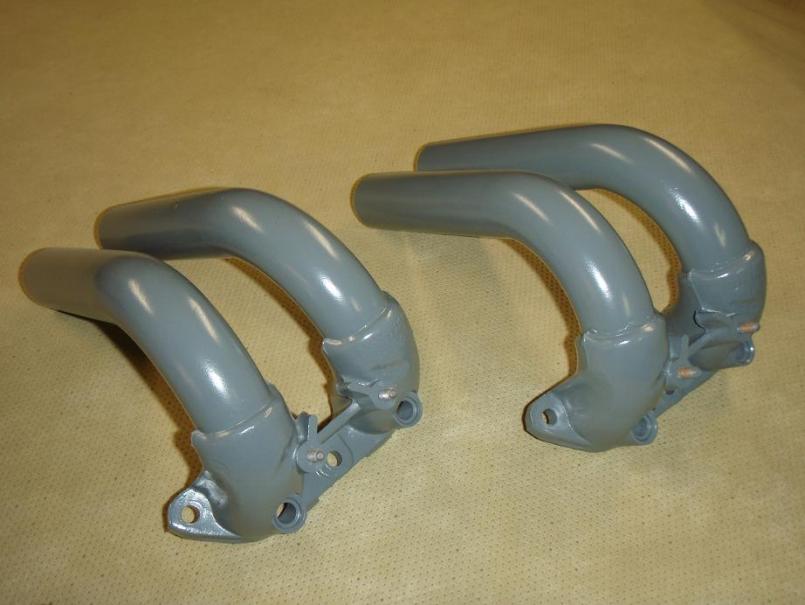
Posted by: MrKona Dec 27 2009, 08:23 PM
But they don't fit the intake housing!
Oh well, looks like I have to clean and paint my existing tubes, and drill an additional hole. I was hoping to make this look really clean with factory 3-stud tubes. That's it for now..
Oh yeah, one more shot - rear tins installed...
Attached thumbnail(s)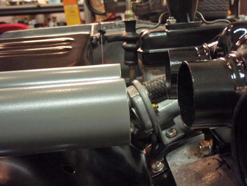
Posted by: MrKona Dec 27 2009, 08:29 PM
Wow, your engine looks great.
Your photos are so clear and focused. So much better than most books that
are supposed to teach you about engines. I almost think Hanes found the
grungiest possible car and then took the worst possible pictures.
How are you lighting the photos? Are you using any flash?
Can you show how to set the valve clearance?
John
Hi John, sorry for the long delayed response. I took the close up pictures with an old Nikon Digital, which I unfortunately no longer own. Light was usually from the camera flash, but some of the close-ups, I just used a shop light and turned the flash off. The flash just drowned out everything in glare. I rested the camera steady on the engine and held the camera as still as possible.
As far as setting the valves, I used the standard method with a feeler gauge.
By the way, I've really enjoyed your restoration thread!
- Bryan
Posted by: enikolayev Jan 30 2010, 08:40 PM
Regarding the oil galley plugs, before you tap the holes for 3/8" NPT, it makes the job far easier and cleaner if you drill out the holes with a 37/64" drill bit.
Just an FYI for anyone attempting this. I screwed a few threads when i tried it without drilling. The drill bit saved my case.
Hope it helps.
Posted by: Cevan Feb 26 2010, 01:35 PM
But they don't fit the intake housing!
Oh well, looks like I have to clean and paint my existing tubes, and drill an additional hole. I was hoping to make this look really clean with factory 3-stud tubes. That's it for now..
Oh yeah, one more shot - rear tins installed...
Those look like 2 liter intake runners for D-Jet FI. They won't work with an L-Jet plenum.
Posted by: Thomas J Bliznik Feb 26 2010, 01:51 PM
But they don't fit the intake housing!
Oh well, looks like I have to clean and paint my existing tubes, and drill an additional hole. I was hoping to make this look really clean with factory 3-stud tubes. That's it for now..
Oh yeah, one more shot - rear tins installed...
Those look like 2 liter intake runners for D-Jet FI. They won't work with an L-Jet plenum.

You need a 2.0 liter D-Jet plenum. I think I have a mint (powder coated) one off a 73. I'll look for it if your interested.
Tom
Posted by: Thomas J Bliznik Feb 26 2010, 03:10 PM
But they don't fit the intake housing!
Oh well, looks like I have to clean and paint my existing tubes, and drill an additional hole. I was hoping to make this look really clean with factory 3-stud tubes. That's it for now..
Oh yeah, one more shot - rear tins installed...
Those look like 2 liter intake runners for D-Jet FI. They won't work with an L-Jet plenum.
You need a 2.0 liter D-Jet plenum. I think I have a mint (powder coated) one off a 73. I'll look for it if your interested.
Tom
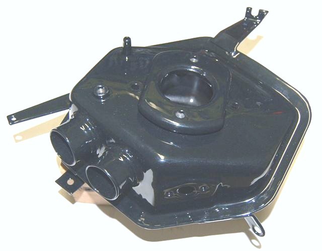
MrKona,
This is the 2.0 liter air plenum you need. Here's a photo.
Tom
Attached image(s)
Posted by: bobhasissues Feb 26 2010, 08:48 PM
[quote name='MrKona' date='Dec 27 2009, 08:29 PM' post='1255735']
Can you show how to set the valve clearance?
[/quote]
As far as setting the valves, I used the standard method with a feeler gauge.
[/quote]
Double check Jake's instructions regarding the valve clearance when using his chromolly pushrods, I believe they are supposed to have zero lash. Snugged up so the pushrods can be turned, but no lash. Hope this helps.
Posted by: MrKona Mar 22 2010, 02:44 PM
I'm back after having worked on "project intake runner conversion."
When we last left off, I had realized that my 2.0 3-hole intake runners would not fit my L-jet plenum. Since the D-jet plenum appears to require the 2.0 D-jet air filter and related pieces, I decided to drill my 4-hole L-jet intake runners to 3 holes. Easy enough, except after further inspection, I realized that it was not this simple, as there is a size mismatch between the base of the two runners where they meet up with the cylinder head. Demonstrated here by comparing the gaskets: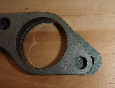
I could simply drill the holes, but cosmetically, this wasn't okay. This is where J-B Weld comes in. Using the 3-hole gaskets as templates, I created a mold to mimic the look of a 3-hole intake. 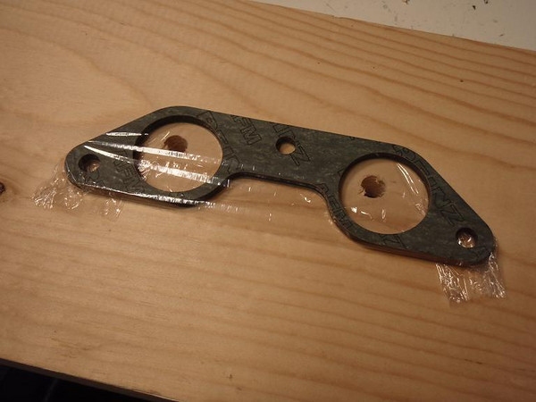
First, I filled in the existing holes: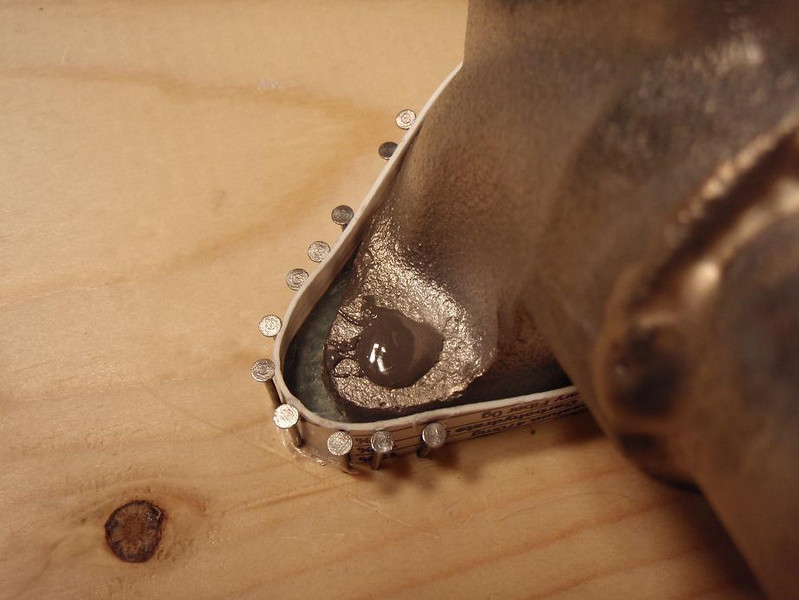
And then the rest: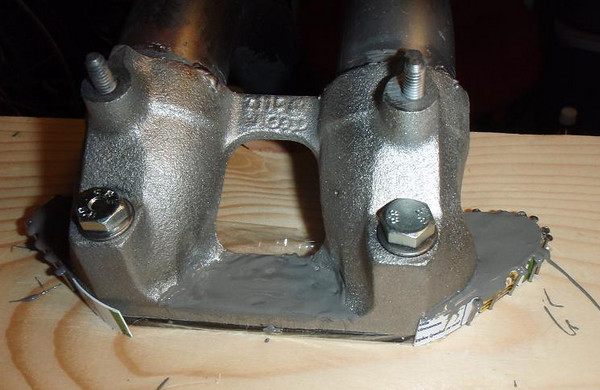
Removed from the mold: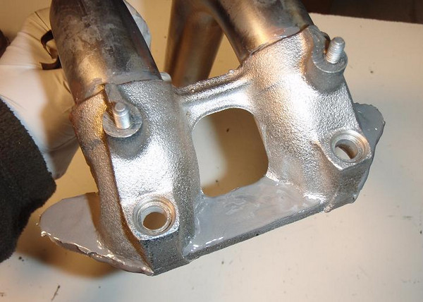
And sanded smooth: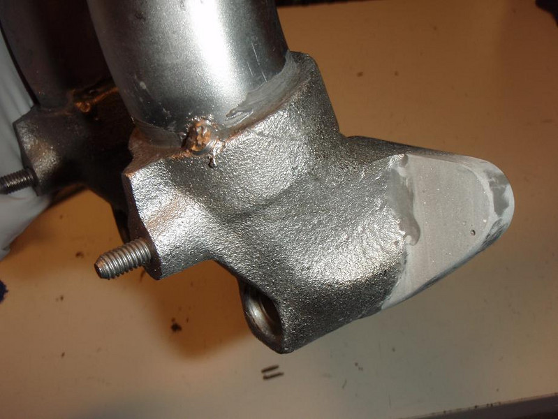
I then drilled the new holes: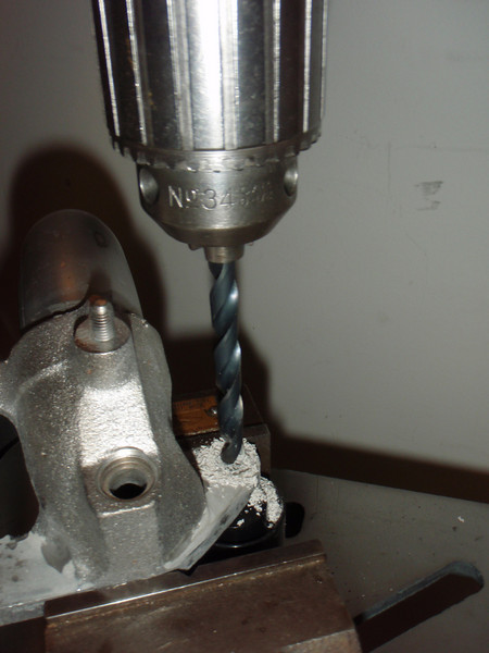
What is not shown here is that I eventually used a template as a "drill bit guide." I drilled the 3-hole stud pattern onto a 1/4" steel plate. It was necessary to use the 1/4" steel plate to guide the drill bit. Even with a drill press and the runner clamped onto the table, the drill press bit wanted to drift to the softer material, in this case, J-B Weld, where the hole being drilled was half on J-B Weld and half on steel. It was the most difficult part of this project.
After paint, the final result: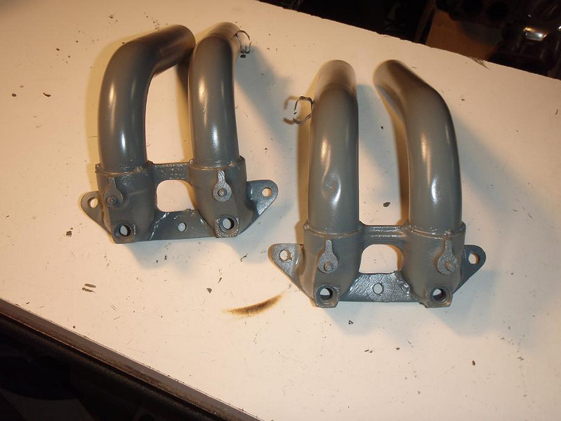
and installed: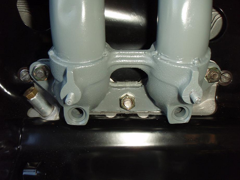
A couple more notes:
1. J-B Weld is rated up to a constant 500 degrees F, so hopefully, it will be okay for this application.
2. I thin the J-B Weld with a little acetone to make it pour easier into the mold.
3. Other Things: This project took awhile because I got side tracked doing a complete restoration on the drill press I was using.. Circle 1950s Atlas, made in Kalamazoo, MI. Great tool, It'll far outlast me.
"Before"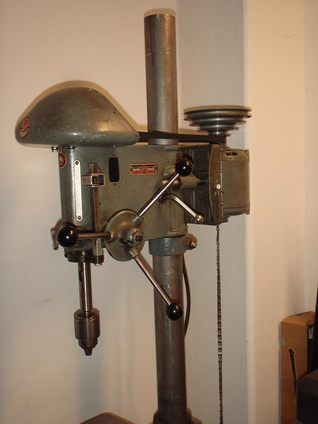
"After"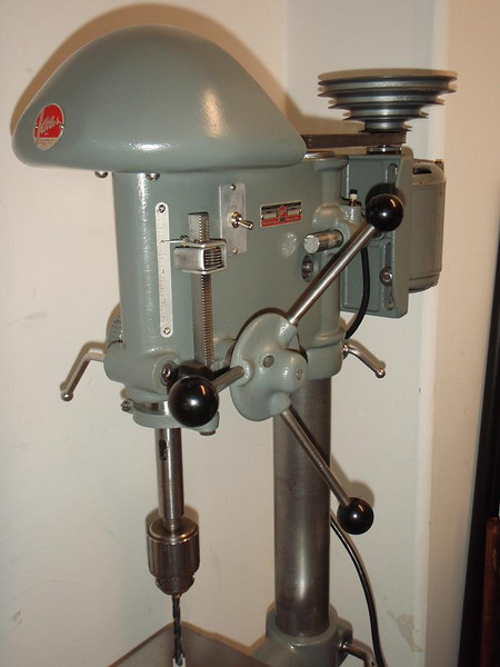
Even recreated the decal. CW for drill presses: 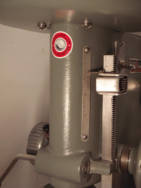
Posted by: MrKona Mar 22 2010, 02:54 PM
And one more of both runners installed..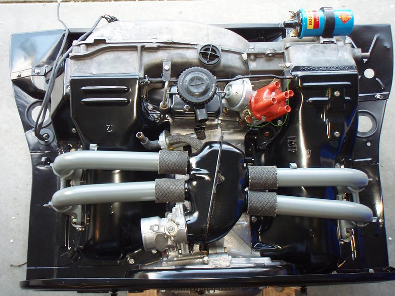
The beauty of this project is that it allowed me to use 2.0 three stud cylinder heads and an L-jet plenum, while maintaining a stock look between the intake runners and plenum. No need for non-stock radiator hoses to bridge the gap.
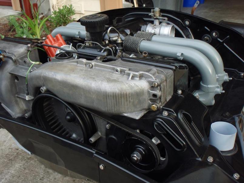
Posted by: MrKona Apr 18 2010, 10:28 PM
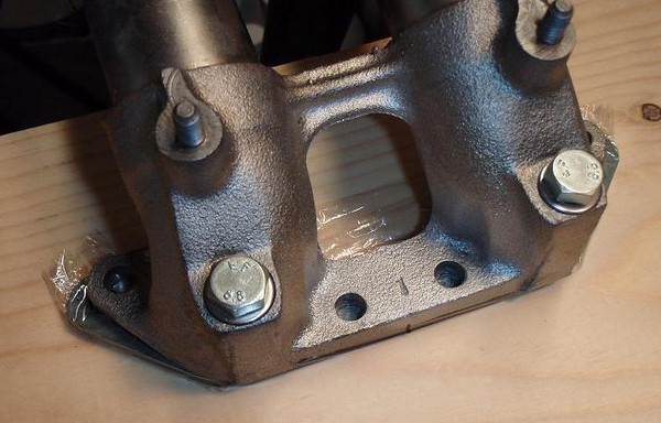
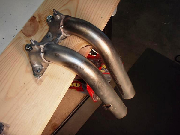
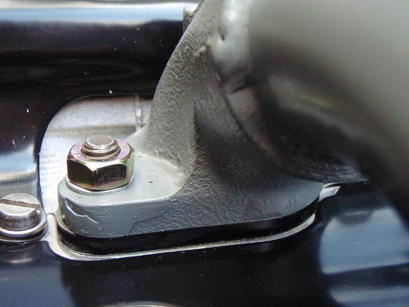
An update of the latest status of my engine rebuild/restoration. I reinstalled the tranny last weekend, and this weekend, I reinstalled the J pipes, flapper boxes, and "Y" pipes (for lack of a better name). I had previously had the J and Y pipes chemically de-rusted. They came back nice clean metal, ready for priming and painting. I used VHT primer and flat gray paint. I think this is pretty close to the original finish. Close enough for me.
Here's a couple shots of the exhaust pieces installed. Notice the Porsche flapper boxes with the stickers still on. I bought these a few years ago from a member here and am finally getting to installed them.
Left side: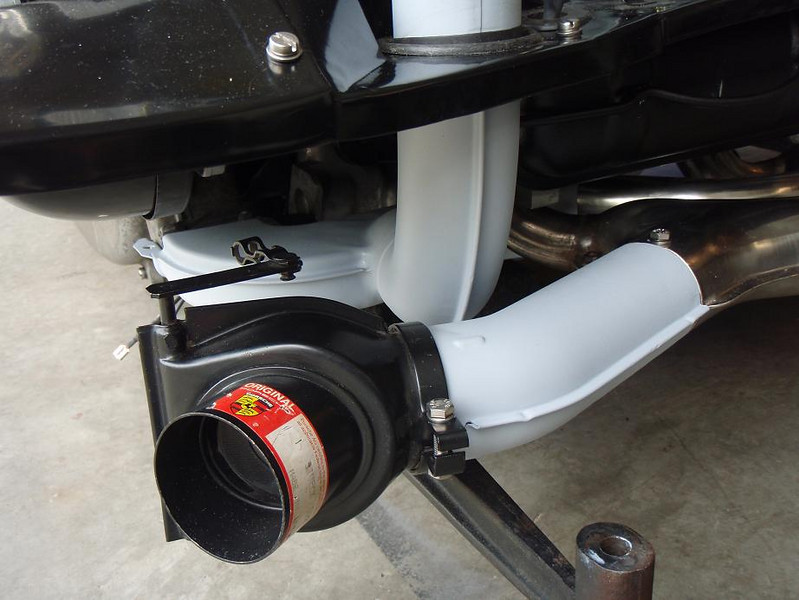
Right side: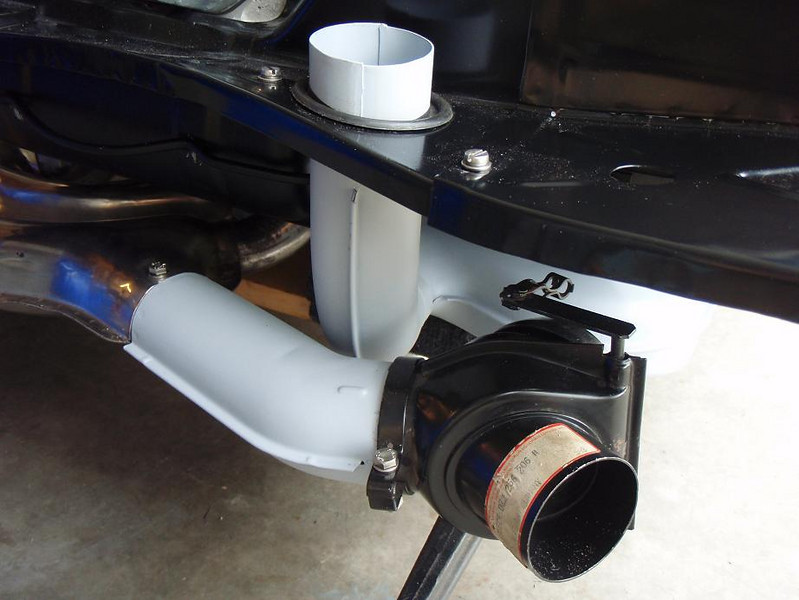
A couple details in this process that I'll point out are the small flaps between the engine shroud and the Y pipes. These originally came with adhesive foam, which mostly disintegrated on my pieces, so I stuck some thin weather stripping to them. Thicker than I would like, but it did the trick and was available at Ace. 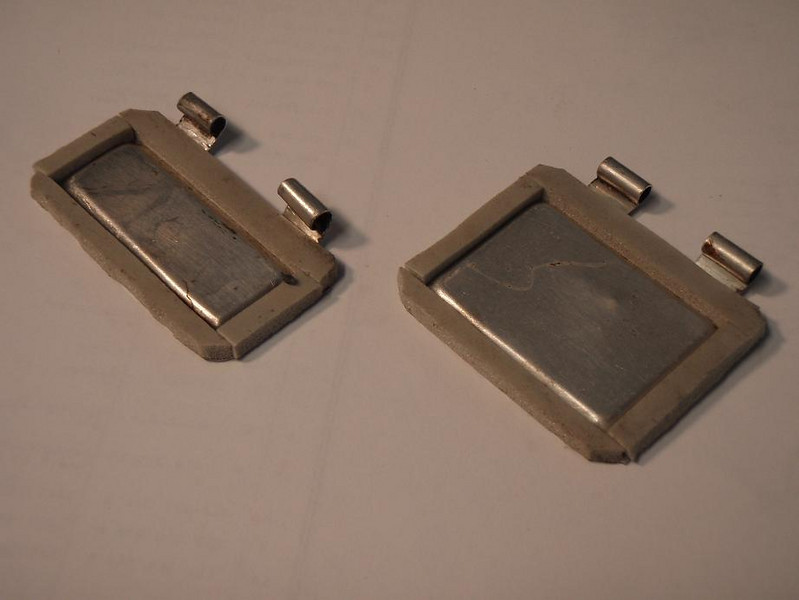
Over these flaps sit the small cover pieces. These pieces originally came with gaskets, which are long gone. I cut a primitive gasket from cork.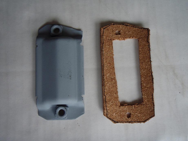
It installed easily, and looks like it will seal nicely.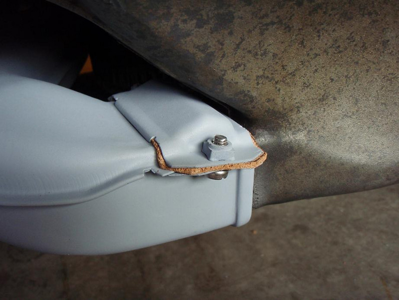
Almost time put the engine back in and free up some garage floor space. I have an old original muffler that I plan on stripping and repainting in gray high temp paint to replace the Sebring.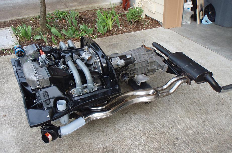
A couple more shots before it goes back in. I especially like how my wife's gardening stuff accentuates the 914. 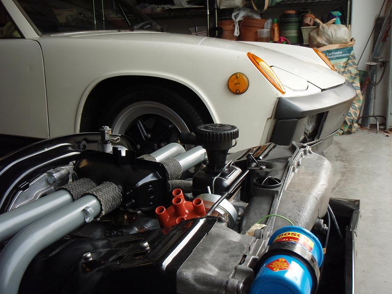
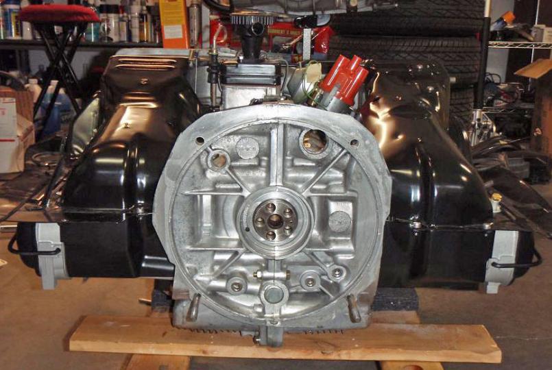
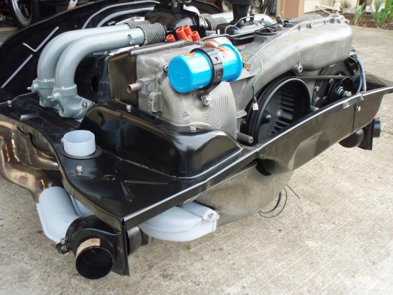
Posted by: MrKona Apr 18 2010, 10:30 PM
A couple more shots of the engine before it goes in..
Attached thumbnail(s)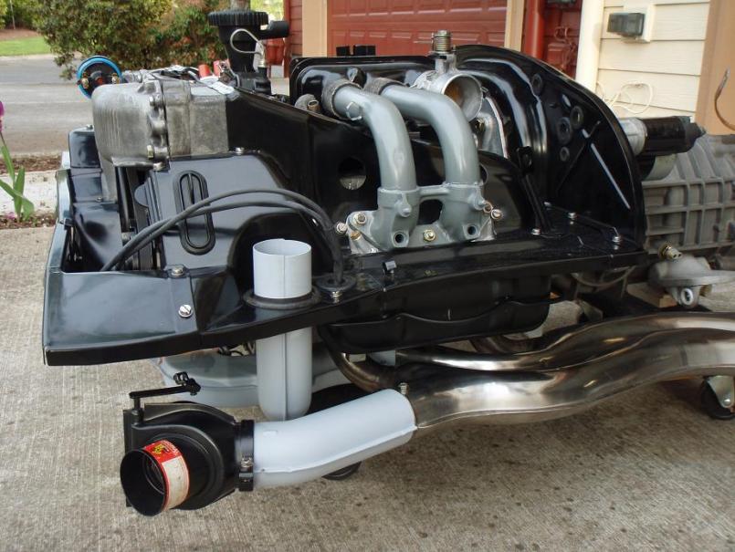
Posted by: Phoenix914 Apr 19 2010, 09:00 AM
Your engine is a work of art, my friend.
Posted by: rwilner Sep 26 2011, 07:08 PM
I am unearthing this thread for 2 reasons
1) this member made some difficult to find heater branch gaskets out of cork that look like they work well
2) what a gorgeous engine.
Powered by Invision Power Board (http://www.invisionboard.com)
© Invision Power Services (http://www.invisionpower.com)