Printable Version of Topic
Click here to view this topic in its original format
914World.com _ 914World Garage _ Spoke's 71 2.056L 914 Progress Thread
Posted by: Spoke Dec 28 2007, 10:59 PM
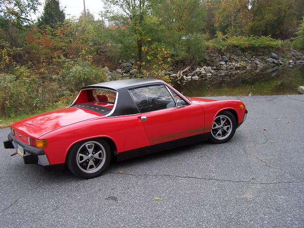
Like Zach said before, just what the World needs is another progress thread. So here it is for my 71 1.7L red ride.
I'm working on an engine swap for my leaky 1.7L with slipping clutch to a non-leaking, unknown GEX rebuilt 1.8L so I decided to concatenate several threads on this car into one progress thread.
Eventually I will sell the red 71 and keep the green 74 as my only 914. For now the plan is to get the new 1.8L engine in the car. The 1.8L has SSHE where the 1.7L in the car has very much corroded stock HE's.
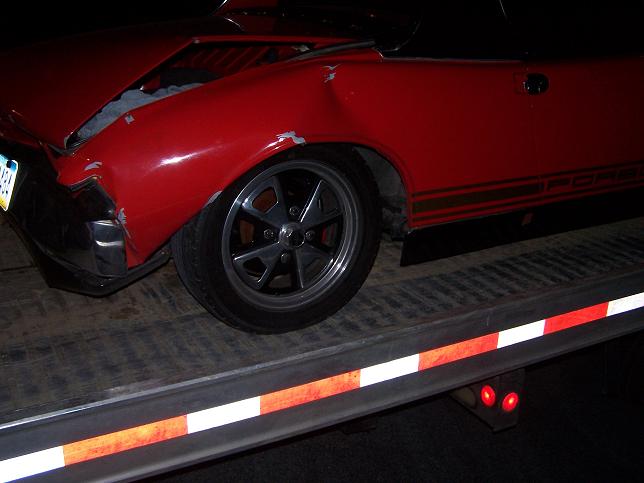
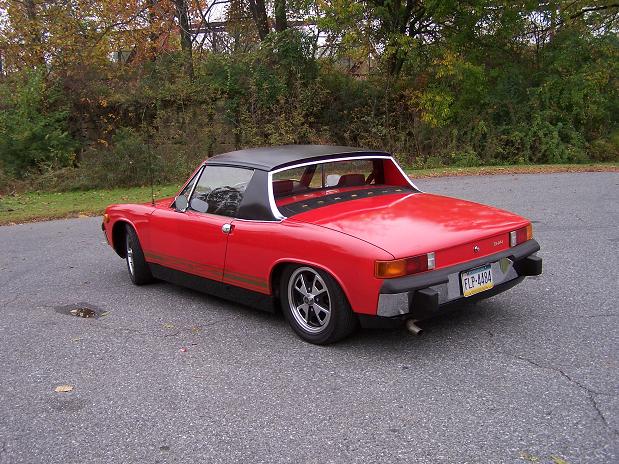
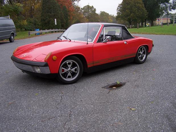
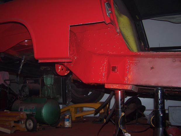
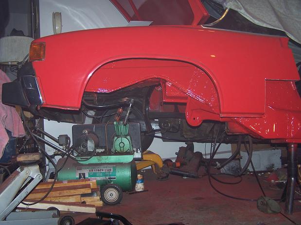
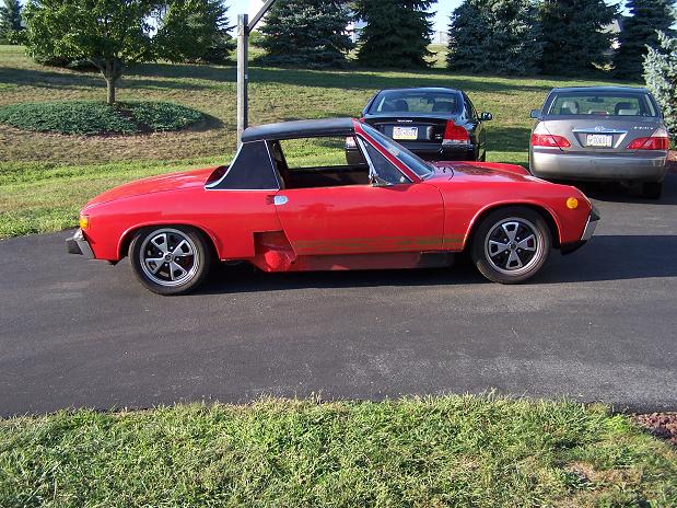
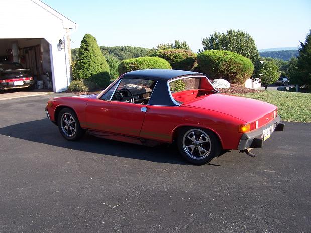
Here's pics after last year's rear end accident that totaled the car and the finished product after many months of rehab.
Attached image(s)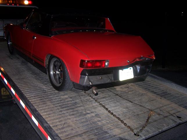
Posted by: KaptKaos Dec 28 2007, 11:11 PM
Whoa! What did I miss??? When did that happen?
Didn't you do an assload of bodywork already for that car?
Aw man, that's a major bummer.
Posted by: Spoke Dec 28 2007, 11:16 PM
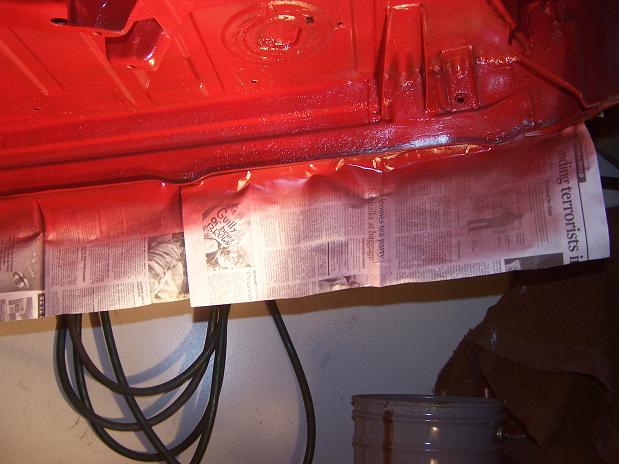
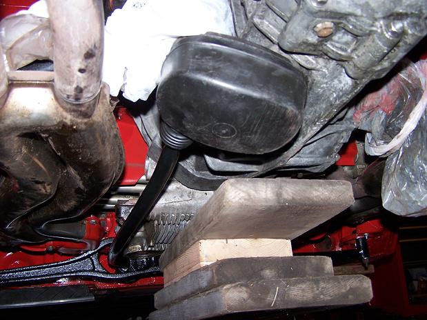
One of the first threads I started on the 914club/914world was a tongue-in-cheek CSOB bandaid thread for the leaky 1.7L in the 71.
http://www.914world.com/bbs2/index.php?showtopic=20489&hl=
My goal was simple. Contain the 4-10 drops of oil each day with as little $$$$$ input as possible.
So I added a skid plate (one of my wife's cookie sheets) under the engine to catch the drips.
As can be seen from the link above, the responses from my "solution" were all over the map.

LOL!!! Thats great.
That's the funniest thing I've seen in a while.

^^^ These are the responses I was looking for.
This is why Jake doesn't get many 914 owners buying his engines... lots of CSOB's out there.
^^^ This one was the catalyst for my sig below (CSOB of PA)
3 years after this "solution", the 1.7L hasn't dropped a drop of oil in my garage or anyone's driveways. I would wipe out the contained oil about once every 2 weeks.
Some responses worried about overheating the engine with the plate. This was not the case as I would drive the car then check the oil temp (normal) and temp of the plate itself. The plate would be warm but not hot at all indicating that it did not affect the temp of the engine.
Posted by: Spoke Dec 28 2007, 11:23 PM
Threads about the rear ender and repairs:
http://www.914world.com/bbs2/index.php?showtopic=43749&hl=
http://www.914world.com/bbs2/index.php?showtopic=44774&hl=
http://www.914world.com/bbs2/index.php?showtopic=62595&hl=
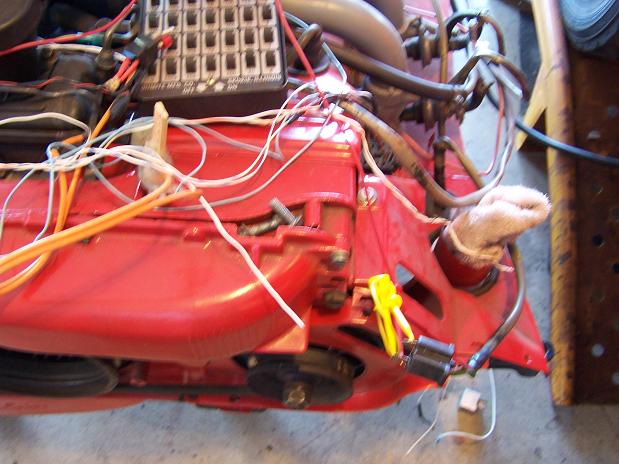
Posted by: Spoke Dec 28 2007, 11:40 PM
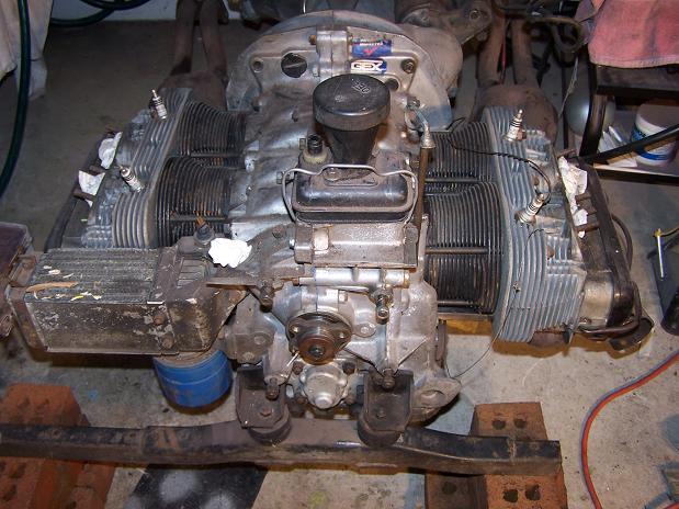
Here's some pics of the donor engine with tin removed. My plan is to clean up the engine and tin and put the Weber IDF40's on the engine.
I have the original FI from the 1.7L but during testing of the components, 6 of the 8 injectors that I had were leaky so I've decided to stay with the Webers.
Attached image(s)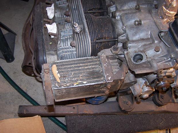
Posted by: Spoke Dec 28 2007, 11:57 PM
Besides cleaning up the engine and tin, I'll check the compression and do a leakdown test.
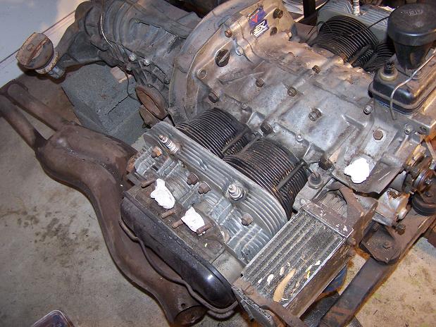
I noticed on cylinders 3 and 4 that the fins from the 2 cylinders were not exactly adjacent to each other. Not sure if the pic captures the offset of the fins.
I was thinking that the cylinders may have a different height leading to leakage at the cylinder/head interface. Leakdown and compression tests should reveal if there are any issues.
Attached image(s)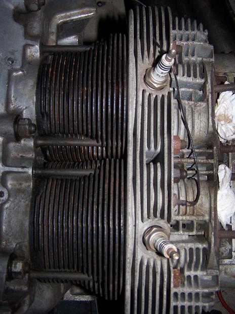
Posted by: Twystd1 Dec 29 2007, 12:09 AM
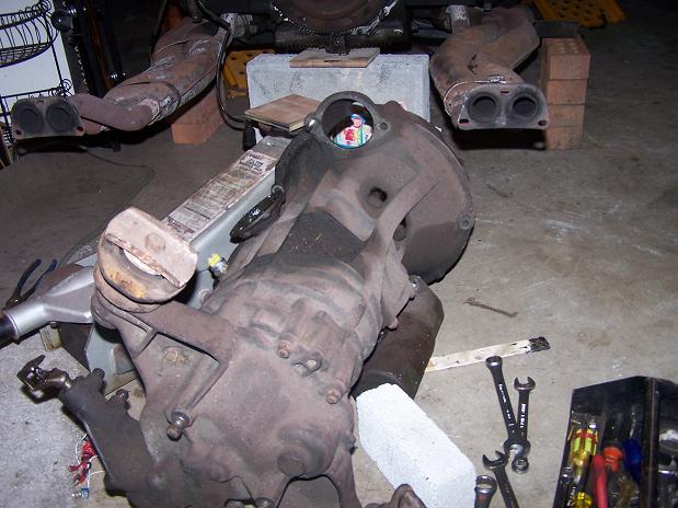
Is that a GEX tag on this engine...????????????
Clayton
Posted by: Spoke Dec 29 2007, 03:33 AM
Is that a GEX tag on this engine...???????????
Yep. I tried contacting GEX to find out what work was done on the engine but since the guy I bought the engine from had bought it from someone else, GEX couldn't (or didn't want to) find the build sheet on the engine to see what work had been done. They needed the name of the owner at the time and the name of the 1st owner (assuming I'm the 3rd) didn't come up in their database.
I've had the engine running out of the car and it didn't leak oil and seemed to run fine given that I haven't loaded it down yet. It looks as if the case was opened as I could see some blue sealant on the inside of the oil breather opening. I assumed the blue sealant was not from the manufacturer.
So, what's the scoop on GEX? Good? bad? Indifferent?
Spoke
Posted by: Spoke Jul 15 2008, 12:43 AM
I've decided to put the original D-Jet FI from this car on the donor 1.8L engine. I've tested the brain and all its inputs and all seems to be working. Here's the link to some of the tests I've done on the brain:
http://www.914world.com/bbs2/index.php?showtopic=82671&hl=Testing
Here's some test results from the MPS. The MPS was leaky as hell so I took it apart, cleaned it, and resealed the unit. Here's the leakdown results for the MPS. This leakdown is better than the leakdown of the MPS on my 2L 74... Horizontal units in minutes.
Attached image(s)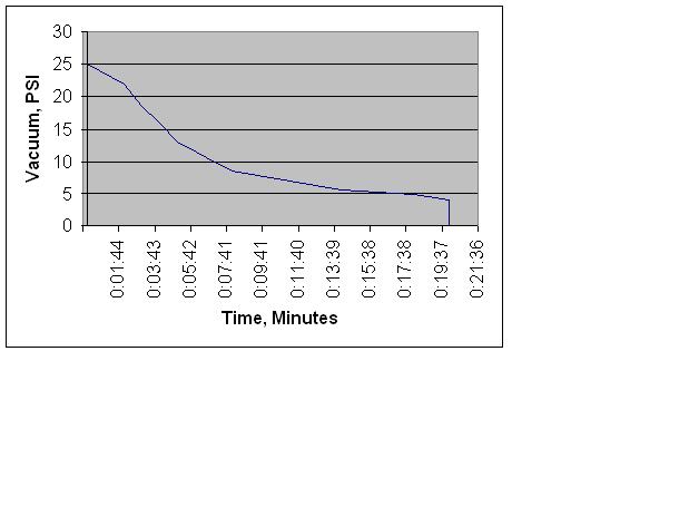
Posted by: Spoke Jul 15 2008, 12:47 AM
With the MPS connected to the brain and with the engine running at 3000RPM (I used an oscillator to simulate the contacts in the distributor), here's the injector pulse width versus vacuum. High vacuum @ 3000RPM is like coasting with the throttle closed. Low vacuum @ 3000RPM is like accelerating with the throttle open. Injector pulse width is in milliseconds.
Attached image(s)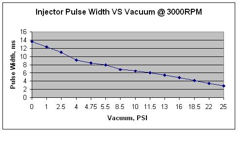
Posted by: Spoke Jul 15 2008, 01:03 AM
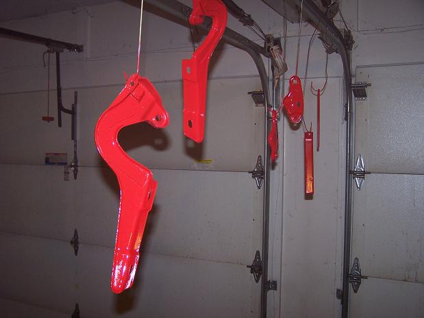
Finally got around to sandblasting the engine tin and painting. Not doing powdercoating for this engine. The car is a salvage title and my interest in the car is for it to run good so I can take my 74 off the road and work on it & still have a 914 to drive. Just want the engine to look good.
Engine rear tin had some stress fractures which needed welding.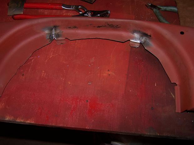
These 4 pieces also needed some welding. I painted the engine tin before welding. Duh.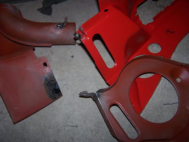
Assorted engine stuff painted. I even painted the fan surround. Hopefully no issues painting these pieces.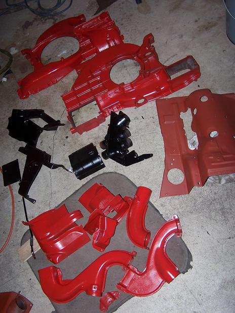
FI runners. Which is the left and which is the right?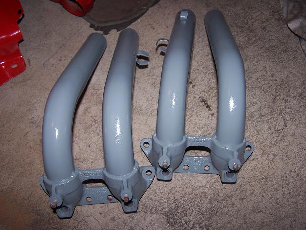
Posted by: Spoke Aug 6 2008, 01:14 PM
Putting the tin back on the engine. The CHT sensor on cylinder 3 was snapped off by the PO or previous rebuild. I couldn't get the remains out so I'll put the CHT sensor on cylinder 2. I closed off the hole in the #3 tin with fender washers and cut a hole for the CHT sensor on #2 tin.
Attached image(s)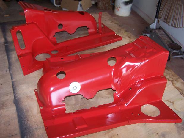
Posted by: Spoke Aug 6 2008, 04:09 PM
Question about #2 "Seal". This is the 1/4 inch spacer between the head and the intake runner.
Is this thing a gasket? It seems more like a spacer. It is a hard material. Do I need paper gaskets on both sides of this "seal"?
Attached image(s)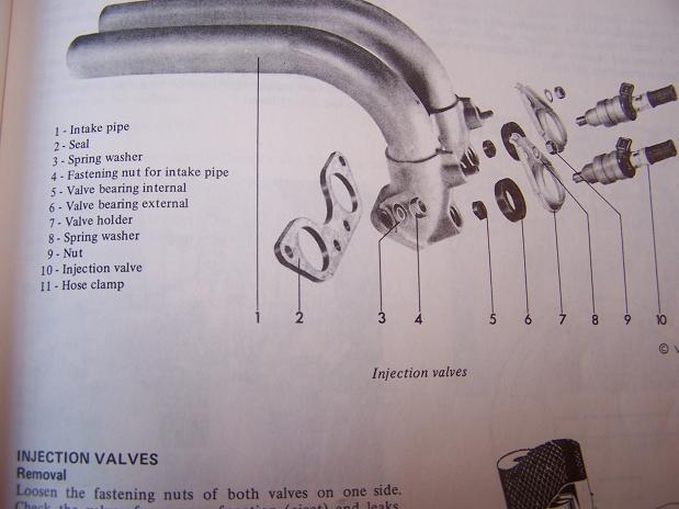
Posted by: fitsbain Aug 7 2008, 09:49 AM
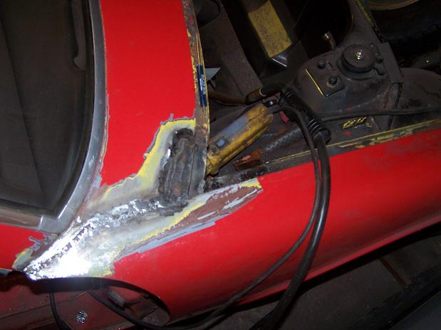
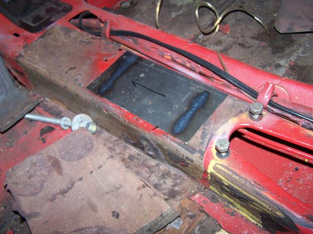
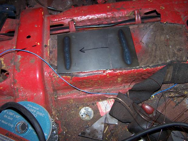
Where are the pictures of that sheet metal I sent you being installed?
Posted by: Spoke Aug 7 2008, 10:36 AM
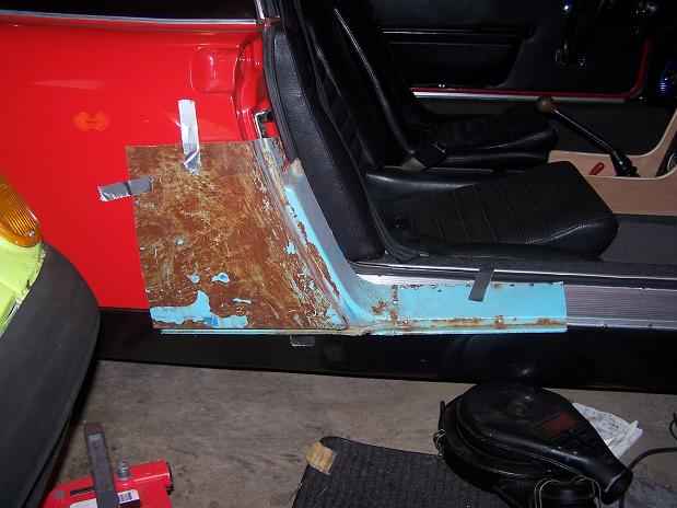
Where are the pictures of that sheet metal I sent you being installed?
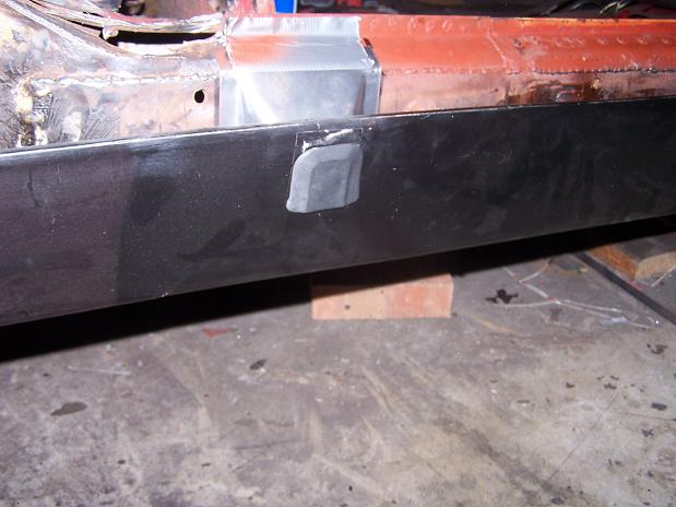
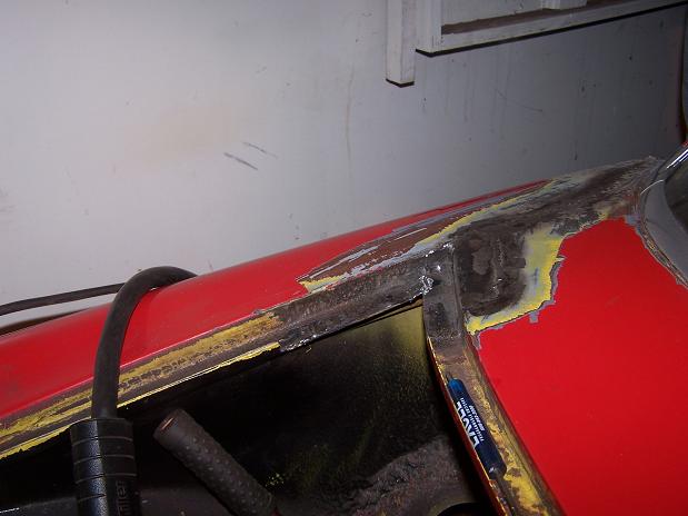
Oh yeah. Almost done with that repair. The duct tape is temporary while the glue dries...
I'm so damn slow doing things. Still working on the engine to put in w/newer clutch so I can drive the car. Then I'll do some major body/Longs work.
Attached image(s)
Posted by: watsonrx13 Aug 7 2008, 12:13 PM
Man, I hope you used that 2-part expoy.... 
-- Rob
Posted by: Spoke Aug 8 2008, 11:45 AM
Got the plenum cleaned up and painted. Checked supplemental air valve, cold start injector, ambient air sensor; all OK. Checked out the throttle switches, cleaned and adjusted. Unit ready to be installed.
Attached image(s)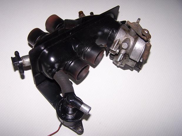
Posted by: Spoke Aug 9 2008, 05:28 AM
Plenum is bolted on. Tin is mostly in place. Ready for intake runners.
Attached image(s)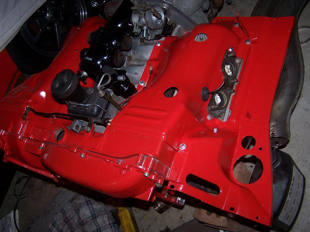
Posted by: Spoke Aug 9 2008, 06:05 AM
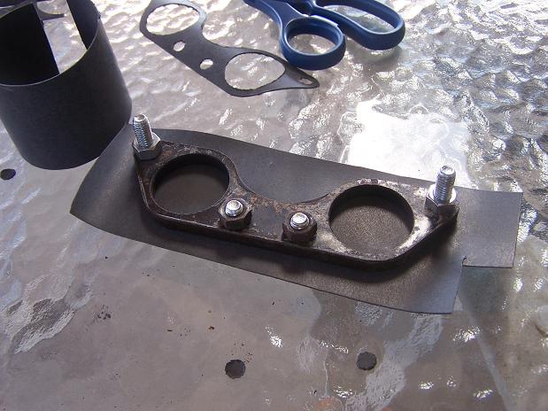
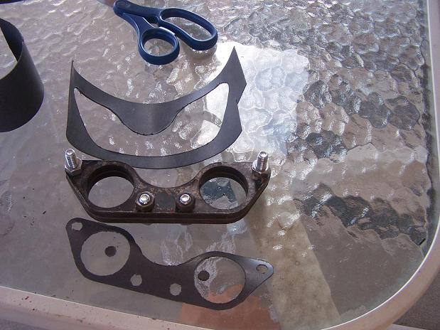
Decided to make gaskets to put between the intake spacers and the runners/heads.
I used 2 extra intake spacers, a couple of nuts&bolts, some gasket material, and a razorblade knife.
Cut the gasket material larger than needed then using the spacers as a template, cut holes for the 4 bolts and sandwiched the gasket material between the spacers.
With the razorblade knife, I cut along the spacers until I cut through the material for the intake holes and outer shape.
Making the 4 gaskets took about 20 minutes.
Attached image(s)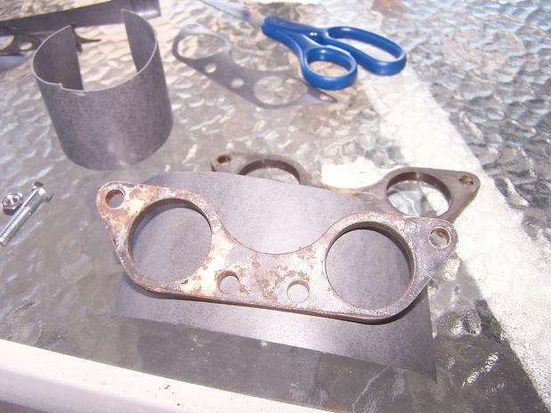
Posted by: neo914-6 Aug 9 2008, 03:25 PM
One of the first threads I started on the 914club/914world was a tongue-in-cheek CSOB bandaid thread for the leaky 1.7L in the 71.
http://www.914world.com/bbs2/index.php?showtopic=20489&hl=
My goal was simple. Contain the 4-10 drops of oil each day with as little $$$$$ input as possible.
So I added a skid plate (one of my wife's cookie sheets) under the engine to catch the drips.
As can be seen from the link above, the responses from my "solution" were all over the map.
LOL!!! Thats great.
That's the funniest thing I've seen in a while.
^^^ These are the responses I was looking for.
This is why Jake doesn't get many 914 owners buying his engines... lots of CSOB's out there.
^^^ This one was the catalyst for my sig below (CSOB of PA)
3 years after this "solution", the 1.7L hasn't dropped a drop of oil in my garage or anyone's driveways. I would wipe out the contained oil about once every 2 weeks.
Some responses worried about overheating the engine with the plate. This was not the case as I would drive the car then check the oil temp (normal) and temp of the plate itself. The plate would be warm but not hot at all indicating that it did not affect the temp of the engine.
Not a bad idea, the Mercedes 300E was designed with a plastic "tray" under the engine that happens to catch oil from the leaky engine. Someone even created a "diaper" to make sure it didn't over flow...
Posted by: Spoke Aug 11 2008, 10:16 PM
Started to reassemble the distributor and noticed the grounding wire for the advance plate was broken off. I couldn't figure out how to reattach the wire to the advance plate so I made a little wire connector and used a small length of flexible teflon wire. The wire connector will go under the screw for the points and the other end under the hold-down fastener for the advance plate.
Attached image(s)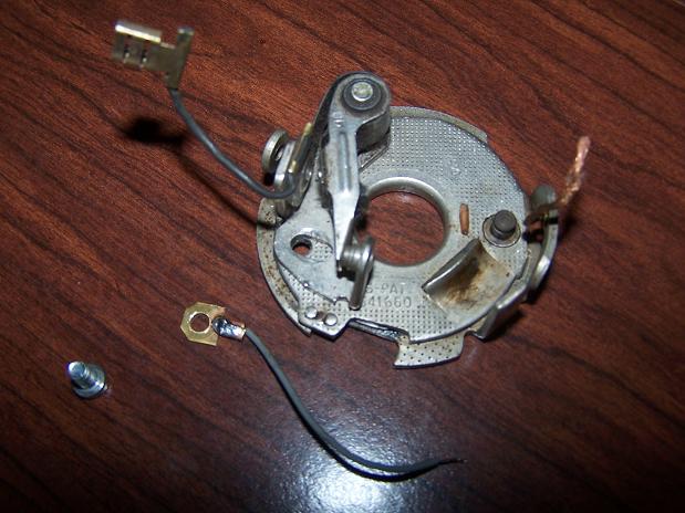
Posted by: Spoke Aug 11 2008, 10:25 PM
When I installed the distributor, I noticed that when at TDC, the distributor was not pointing to the #1 spark wire. Turns out the distibutor drive was off by about 180 degrees. So to double check TDC, I had to pull the valve cover.
Once at TDC, I used a dowel rod to remove the distributor drive and set correctly.
Attached image(s)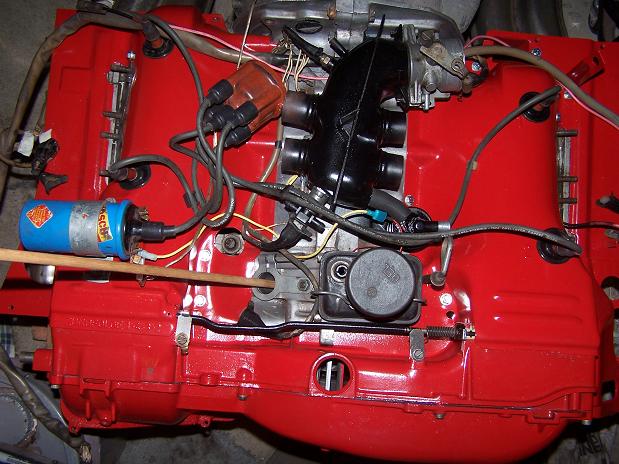
Posted by: Spoke Aug 11 2008, 10:32 PM
Got all the FI stuff on the engine that is needed to fire it up. I'll use the red 914 to provide the fuel from its tank. I have long hoses to run the feed and return to the engine which is sitting beside the car.
I connected the return line to the pump and it started leaking badly. So I tried a second pump that had a marginal leak (a drop an hour) and it too leaked badly. The leak in both came out through the electrical connector.
On both pumps, I had just the return line connected, not the feed. Dammit. Looks like I'm in the market for a new fuel pump.
Attached image(s)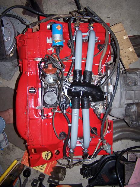
Posted by: Spoke Sep 6 2008, 11:22 AM
Woo Hoo! 
it is alive. Running on FI now and sounds good. Still have an issue with the points as I think I installed a used set and they were dirty and/or not adjusted properly. No spark at first. Readjusted and cleaned them and it runs good. Starts right up and idles nicely.
Haven't run it for more than a minute for a good reason: The engine exhaust is pointing to an interior wall and I get gassed out quickly. Open all doors and windows and leave for 1/2 hour or so. Got a box fan in the window pointing in but still got to move the engine.
I'll put the engine back on a furniture dolly so I can move it around and point the exhaust out the garage door.
Here's the current setup. The Optima powers the engine. The jumper cables provide heavy current to the starter. The battery charger keeps the battery charged as I haven't installed the alternator yet. I'll pull the alternator out of the car and decide which alternator to use at that time. The orange wire leading to the engine power the FI brain. This is the same harness I used to test just the brain and FI equipment.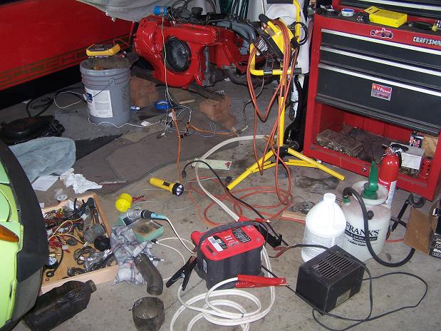
The brain is sitting on a bucket right now. The bracket for the brain is heavily rusted so I don't know how I'll mount it yet. I don't want to do much work like grinding on the brain as to cause internal damage.
The fuel pump takes fuel (and returns it) using the existing connections in the red car. I'll be putting in SS center lines when the engine comes out. The pump is powered by the brain through a relay sitting on the floor in front of the fan.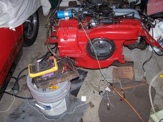
Installed the stock muffler from the red car. Initially I had run the engine with no muffler and it was loud. Installed the muffler hanger too to hold the SSHE in place.
Right behind the starter is a toggle switch to energize the coil and a push button switch to turn the starter on.
I didn't connect the FI brain input to the starter so when I hit the starter, I have to also press a pushbutton on the FI temporary harness so the injectors fire longer during starting. Benefit of having a separate "starter" switch on the FI harness is I can press the FI harness "starter" button if the engine starts to die, giving the injectors a longer duration and keeping the engine running. Sort of like choking a carbed engine.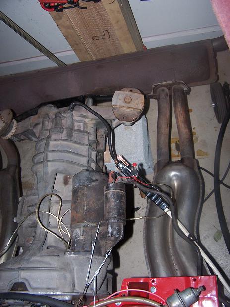
The only items left to mount for the FI are the decel valve and air cleaner.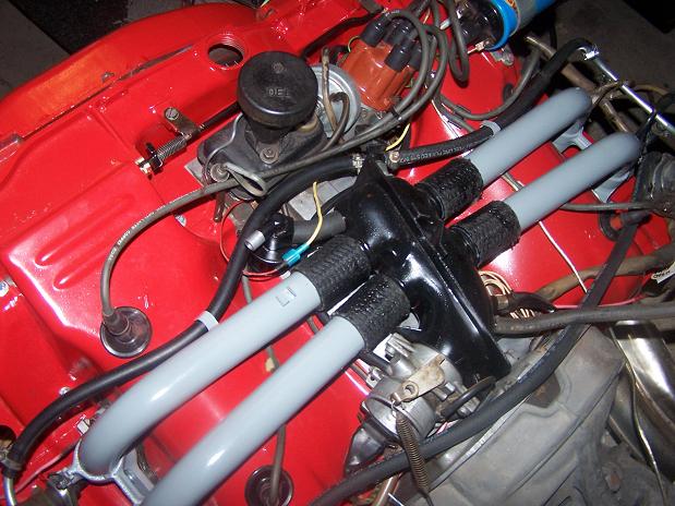
Posted by: Spoke Sep 8 2008, 11:20 PM
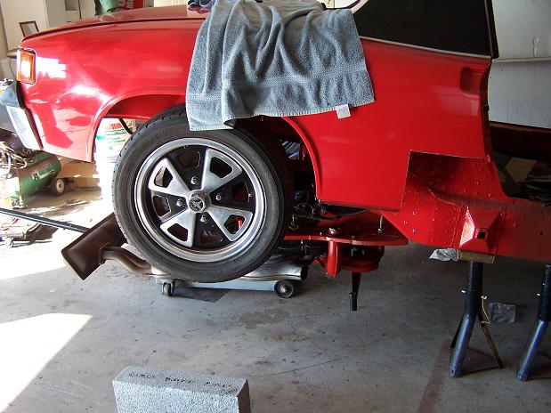
Put the engine on a furniture dolly today. Now I can move it towrds the door and do more long term running.
Ran the engine for 5 minutes today. Starts right up. Idles nicely. Revvs good. Ran it long enough to burn some of the residual oil off of the SSHE. Both smoked at first then stopped after a few minutes.
Got the red car ready for its lobotomy.
Attached image(s)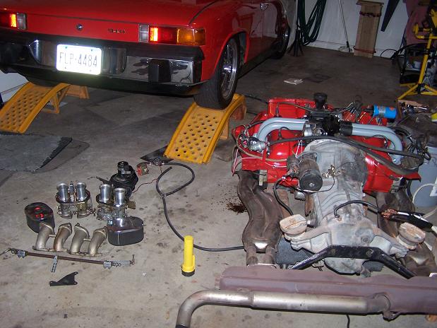
Posted by: Spoke Sep 8 2008, 11:22 PM
Started removing stuff from the engine. These IDF40s and hardware will be for sale now that the new engine is running good on FI.
Attached image(s)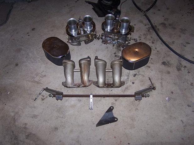
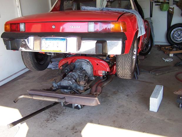
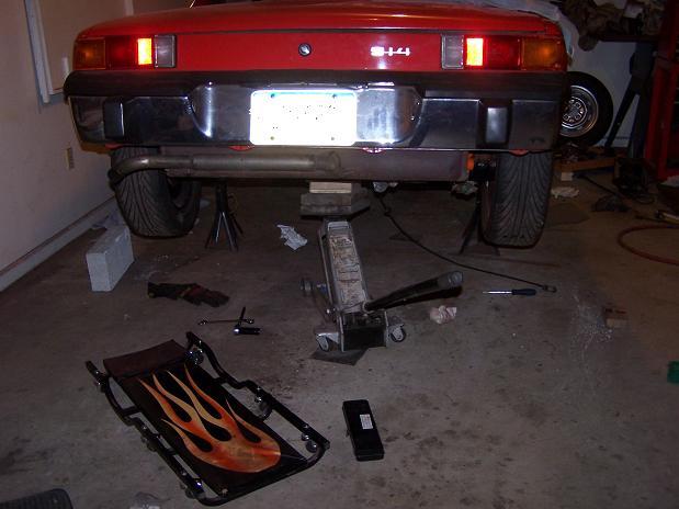
Posted by: Spoke Sep 15 2008, 03:23 PM
My first engine drop. Piece of cake. Put my floor jack under the bottom rear of the engine, removed the front and rear bolts and drop. One hand turning the jack handle and the other hand balancing the tranny.
Does anyone want a 1.7L engine? I have no use for this lump.
Attached image(s)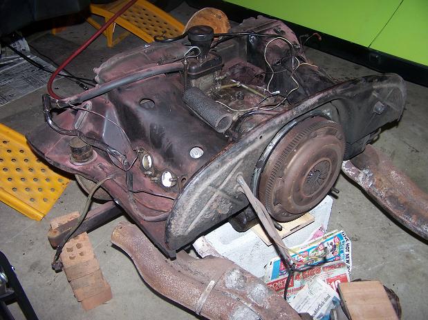
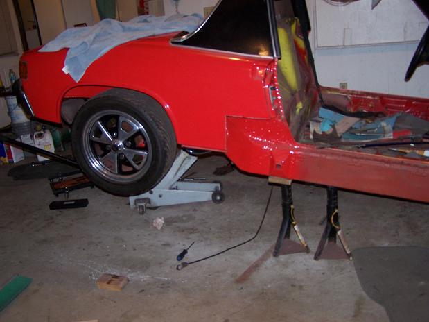
Posted by: Spoke Sep 15 2008, 03:26 PM
The while-I'm-in-there syndrom will include SS fuel lines and clutch tube repair. You can see in this pic how I supported my rusted out firewall around the clutch tube. A little angle iron and U-bolt kept the clutch tube from joining me in the interior. This repair held for 2+ years.
Attached image(s)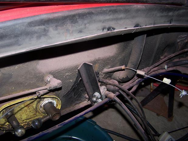
Posted by: Spoke Apr 7 2009, 06:10 PM
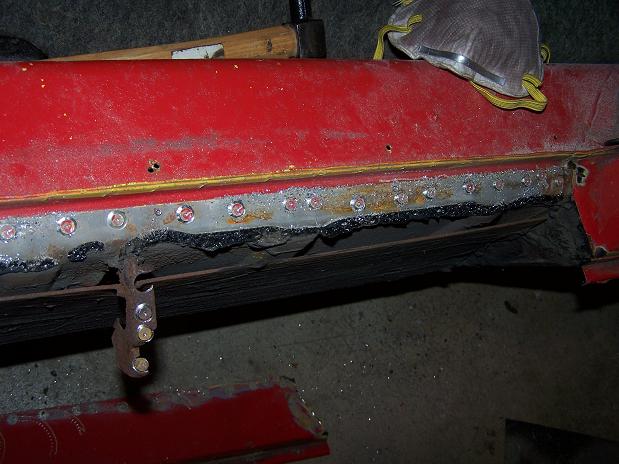
Started work on reinforcing the longs. The repair done before was basically overlay a piece of steel over the bottom and outside of the rusted out long. The bottom of the outside piece is seam welded to the added bottom piece but the top was mostly left unattached to the top of the existing rusted out long.
Attached image(s)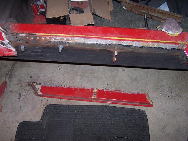
Posted by: Spoke Apr 7 2009, 06:34 PM
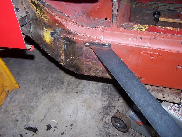
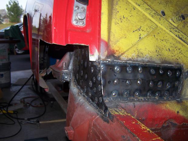
Cut the lower part of the fender off. The door jamb was rusted out so I have a replacement piece to put back on.
The bolts where put on by me when I realized that the top of the long was not welded. The bolts tightened up the longs a good bit. The top of the outside long is completely rusted away under the door jamb.
The inner fender is a replacement piece. The original inner wall was rusted away and this piece was welded only from inside the engine compartment.
The suspension console has been replaced too.
Attached image(s)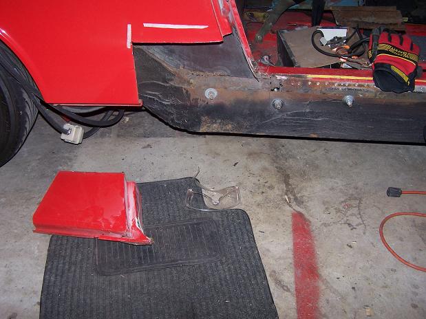
Posted by: barada Apr 7 2009, 06:46 PM
Cut the lower part of the fender off. The door jamb was rusted out so I have a replacement piece to put back on.
The bolts where put on by me when I realized that the top of the long was not welded. The bolts tightened up the longs a good bit. The top of the outside long is completely rusted away under the door jamb.
The inner fender is a replacement piece. The original inner wall was rusted away and this piece was welded only from inside the engine compartment.
The suspension console has been replaced too.
Nice thread. I am trying to pick up a non running 1.7 car now, interesting to see your rebuild.
Posted by: Spoke Jun 1 2009, 09:45 PM
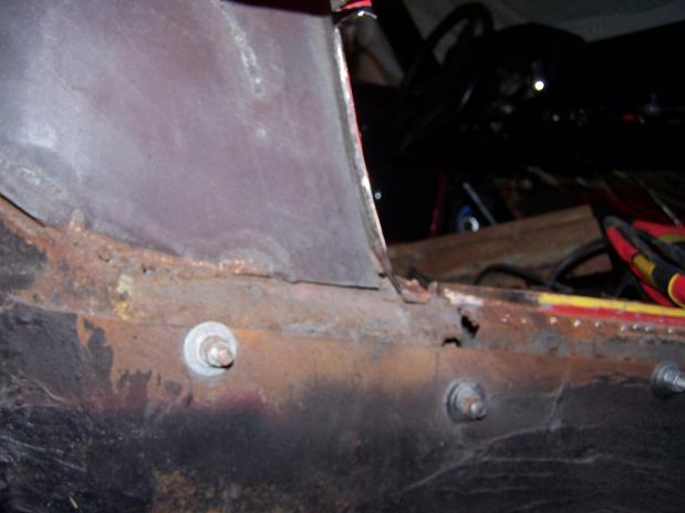
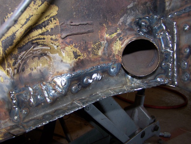
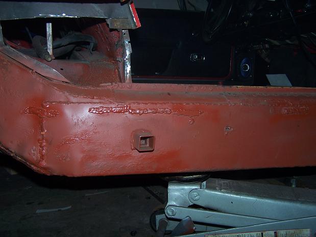
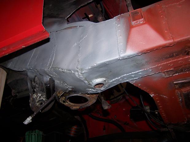
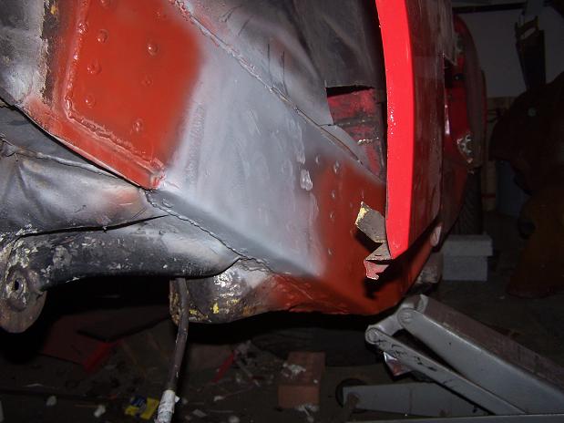
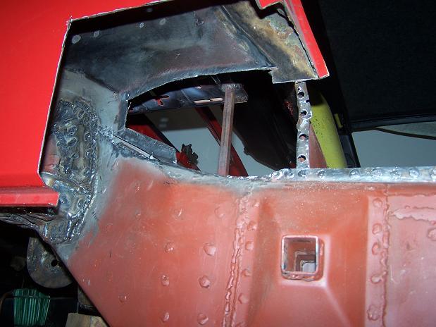
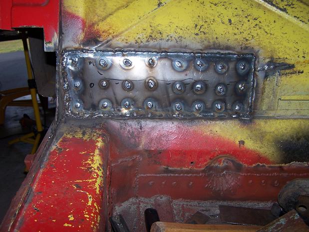
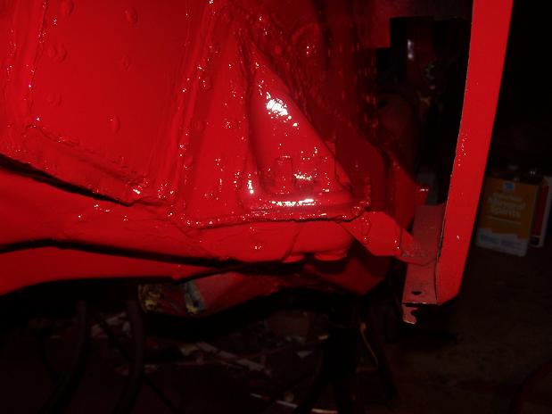
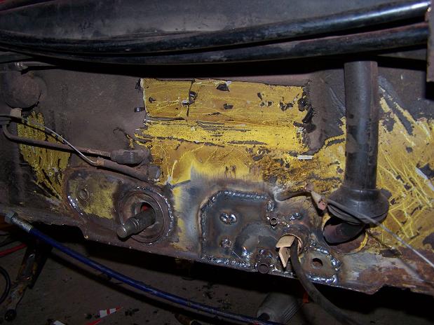
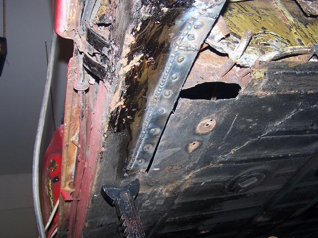
There is basically nothing left of the lower part of this long from the front to the rear. In this area there was nothing left of the top outer long. This will be replaced with a new piece. 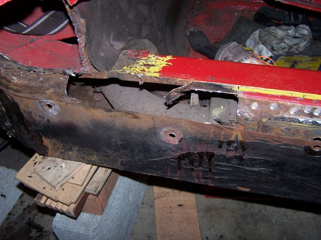
Here is the hell hole from the outside looking in. The black metal inner fender is a replacement piece that was welded from the inside but not outside. So I cut off the bottom of the piece to rebuild all of the metal of the inner fender and weld all seams that I can.
Notice the rust through on the outer suspension pickup. This is before I started poking it with my screwdriver.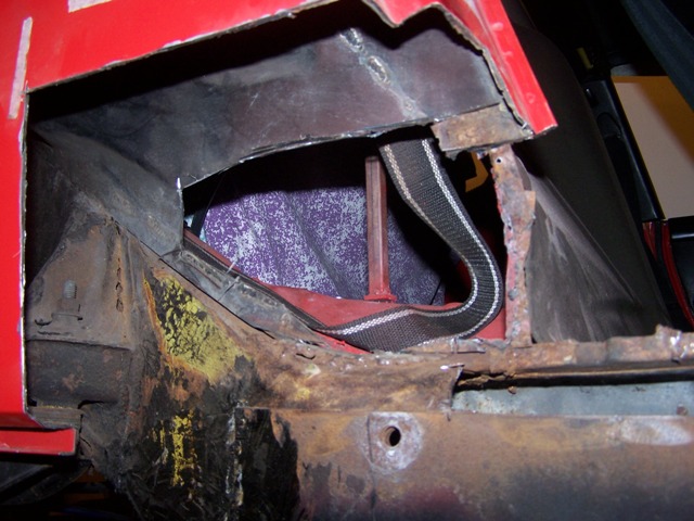
This is the front of the 16 gauge plate that replaces the outer long panel. It is attached to the chassis only about 1/2 way up the plate as the previous work was done with the sill plate still attached. This will all be welded up.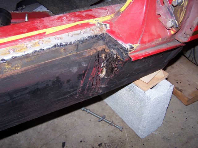
Here is the plate looking straight down. The entire top of the plate was not welded to anything. The top of the original long was basically loose on the outside.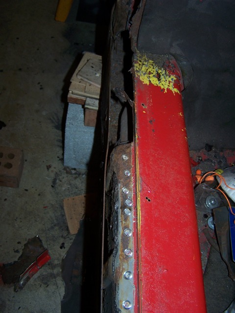
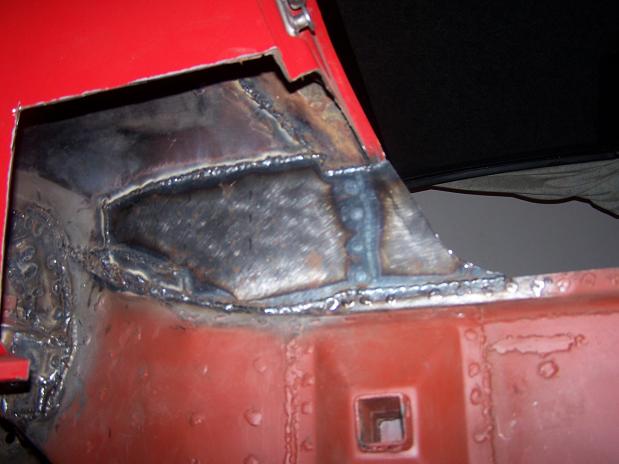
Posted by: Spoke Jun 1 2009, 09:57 PM
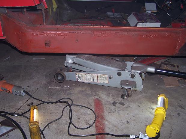
Preparing to weld the steel plate to the existing long metal. The plate will be welded at the rear and on each of the ribs of the existing outer long. The bottom of the outer long is gone so the vertical clamp is setting the height of the long before I weld.
Before doing any welding, I replaced the door to make sure it closed properly. When welding on the steel plate, I welded in one place and waited for the plate to cool as to not deform the long.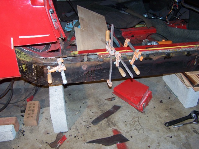
This plate was welded from the hell hole but not edge welded from the cabin. I edge welded it from the cabin.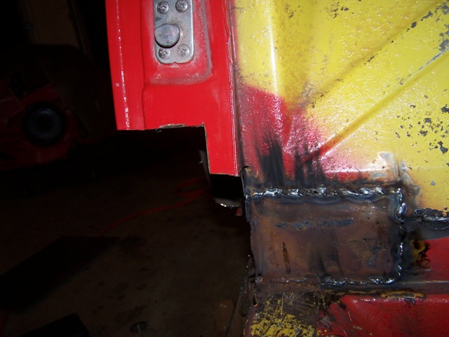
The rear of the plate is now welded. Notice the suspension pickup after poking with a screwdriver. Not sure what I want to do with this yet. The inner suspension pickup has already been replaced with a new piece.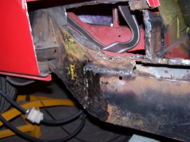
The new plate is being welded on. I welded a small section then let it cool so as not to deform the metal.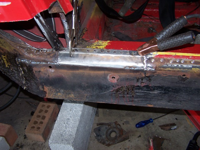
Posted by: Spoke Jun 1 2009, 11:01 PM
I would make more progress on the 914 if I didn't play with this toy as much. It says "turbo" on the back but it should really say "WOW". This car has some giddyup with its 282HP when the turbo kicks in above 3K RPM.
Attached image(s)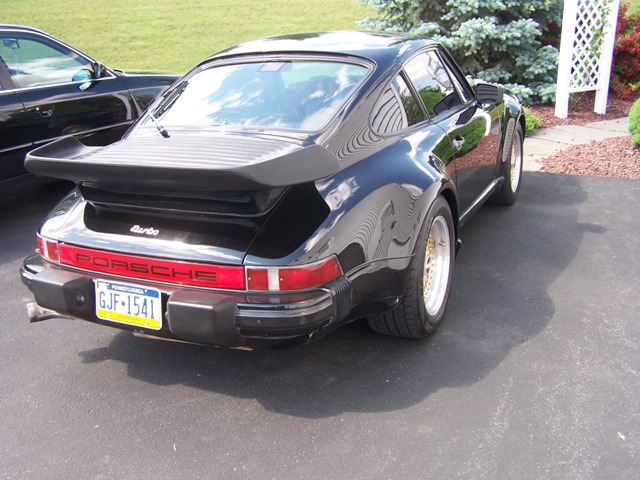
Posted by: Spoke Jun 1 2009, 11:06 PM
The replacement plate is welded in. Like the steel plate, this is 16 gauge steel. I have an Engman's interior long kit to install also. 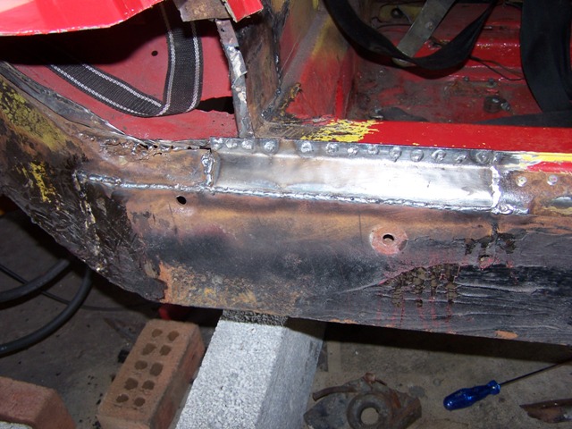
Now all the ribs are welded on top to the steel plate. Also made small fill plates and welded them. I will add ribs on the steel plate from angle iron next. It doesn't look pretty but it sure is strong now. Luckily I have rocker panels to cover this mess.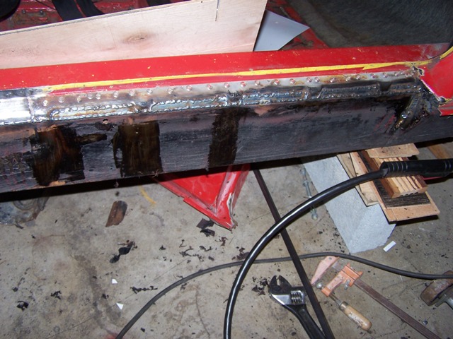
Posted by: Spoke Jun 4 2009, 09:36 PM
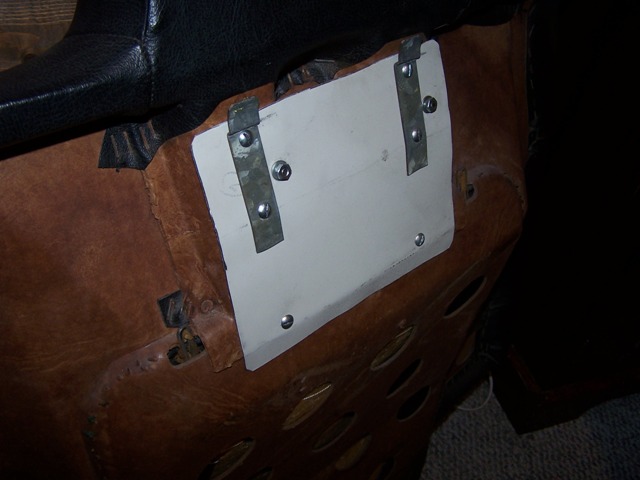
Here's a fix I did a while back when I was refurbishing the packpad. 3 of the 4 clips were gone and the fourth was just hanging on. The PO had used some screws into the backpad and into the firewall to hold the backpad in place.
So I got some old steel from a junked PC case and mounted my own brackets made from some heavy steel straps. Then bolted on the PC case steel onto the backpad.
Attached image(s)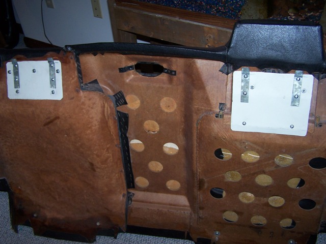
Posted by: Spoke Jun 7 2009, 08:59 AM
Removed all the tar on the passenger side floor. It comes off real easy with a heat gun. This job is probably best done in the winter time as it gets real hot with the gun on.
The front floor pan is in good shape with minimal surface rust. The back pan is not so good with several rust through holes. The 2 putty knifes are sticking in the rusted out part of the lower firewall.
Attached image(s)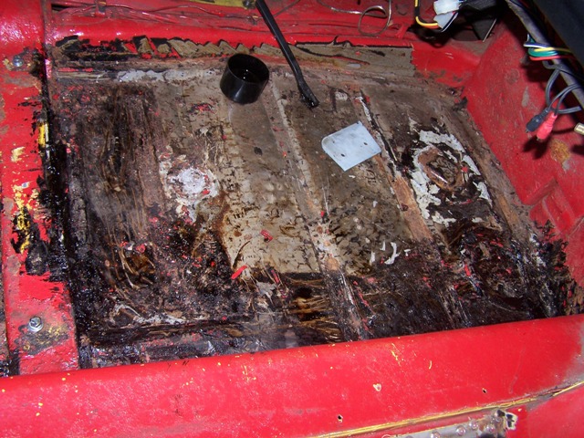
Posted by: Spoke Jun 7 2009, 09:03 AM
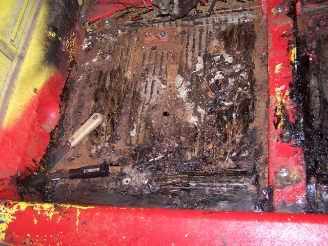
The inside long has been patched from front to back. The patch has only been spot brazed. I'll seam weld the all the patches, then install the Engman's inner long kit.
Question: what is the best solvent to remove the remaining tar? I used a wire brush and mineral spirits to get it partially cleaned.
Attached image(s)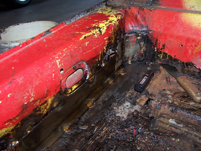
Posted by: charliew Jun 7 2009, 12:35 PM
Where the door gaps still good before you started? Boy there wasn't much support there.
Posted by: Spoke Jul 18 2009, 08:43 AM
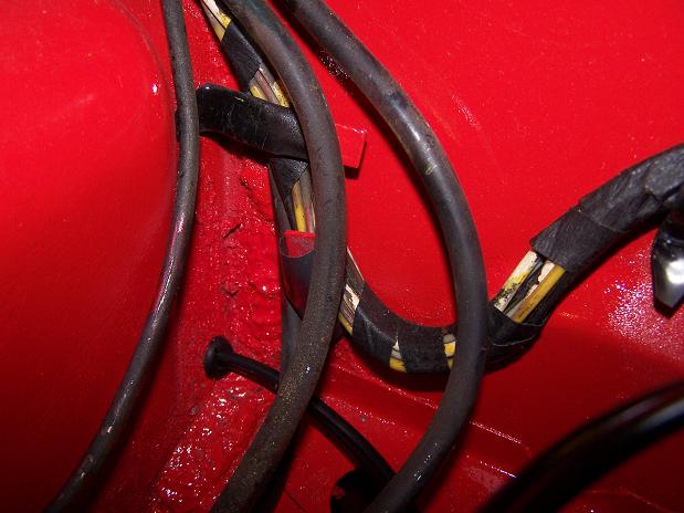
Got the gas tank and center fuel lines out today.
I'll be replacing the plastic fuel lines with steel ones from Racer Chris.
Once out, I wanted to stress the plastic fuel lines to see if they were hardened. I proceeded to twist them, flex them, and bent them until they creased. These lines are very soft and supple.
Some have argued that the plastic tunnel lines are not a fire hazard. These fuel lines would tend to support that theory. At any rate, I'll be replacing them with steel lines.
Attached image(s)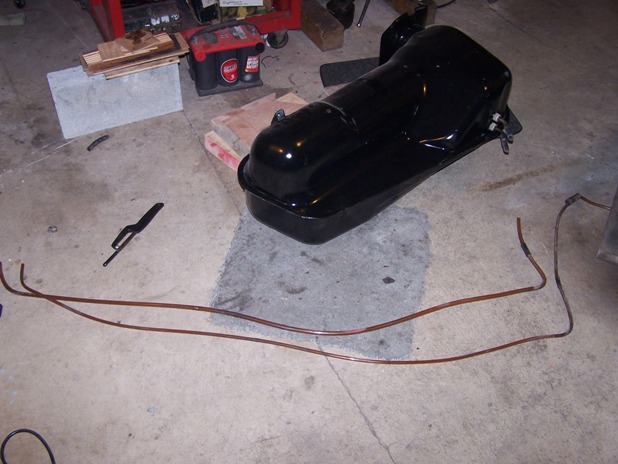
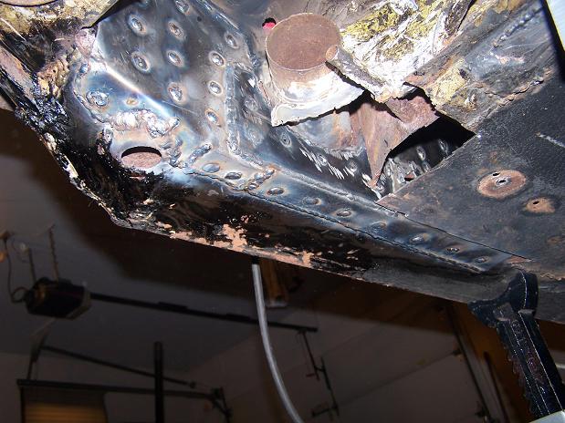
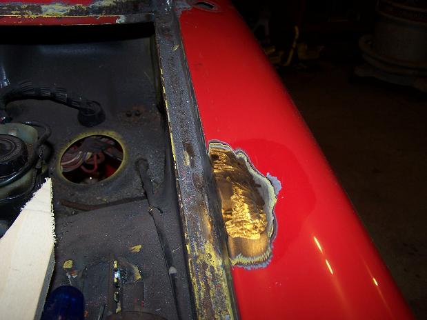
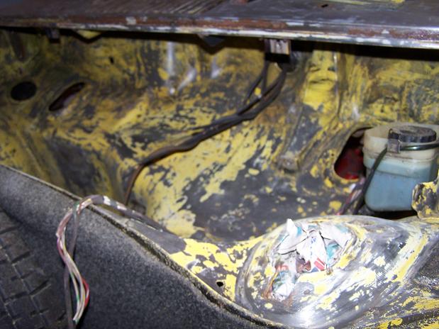
Posted by: Spoke Jul 18 2009, 08:47 AM
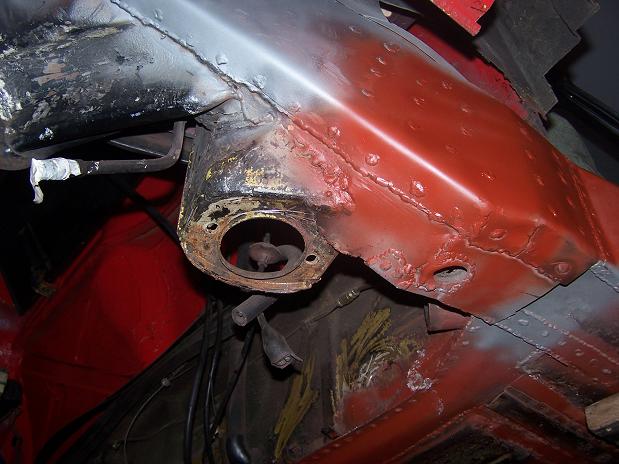
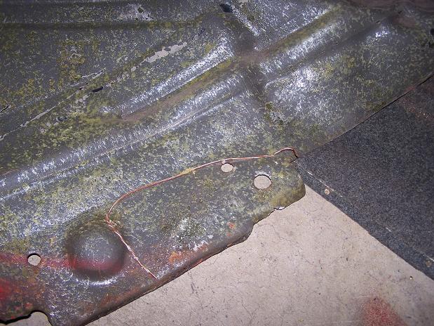
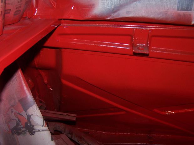
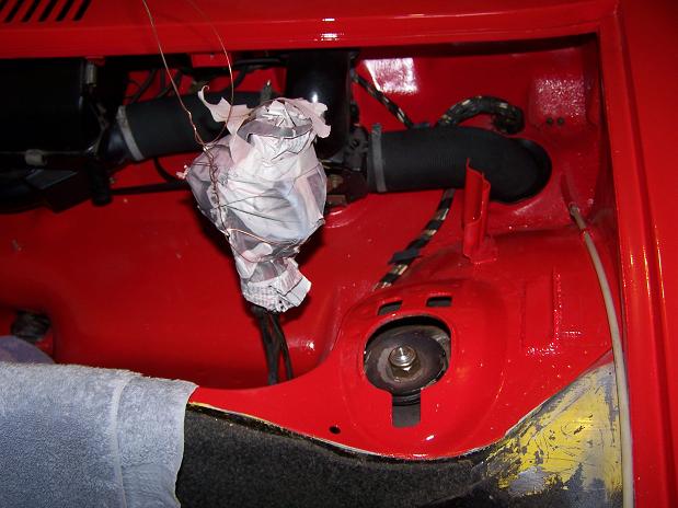
This pic was supposed to show the rust around the heater tube but the fuel pump pigtail got in the way.
The previous fix added extended the "web" that goes between the long and the body by the heater tube. This plate is coming out so I can access the rust around the heater tube.
Attached image(s)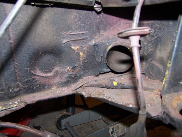
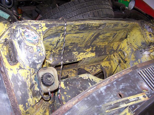
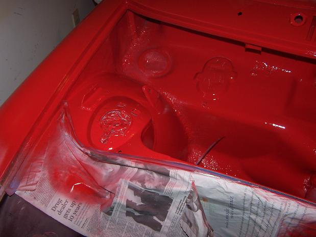
Posted by: Spoke Jul 18 2009, 08:53 AM
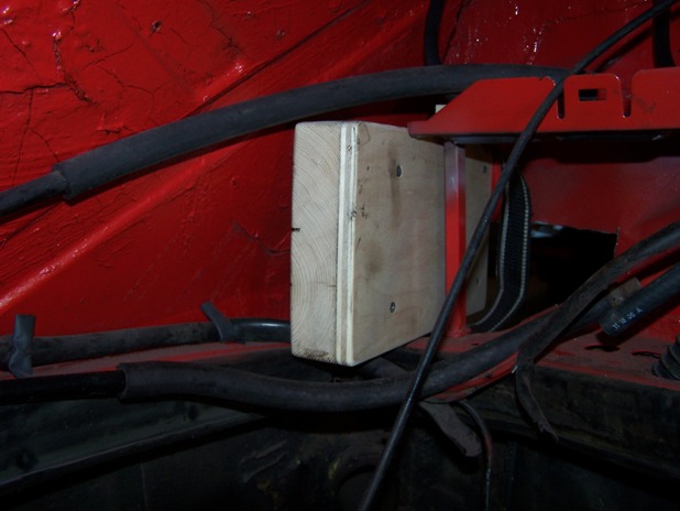
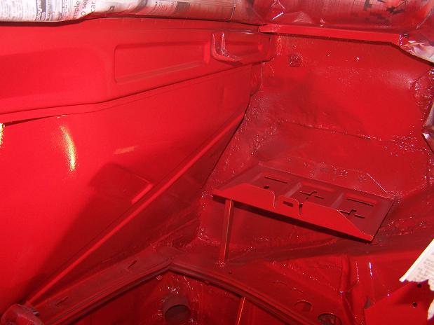
A while back I repainted the trunk and relocated the battery from the trunk to the original position in the engine compartment. I used an aftermarket battery tray and placed the tray in the original position.
At that time, I had a carbed engine and didn't care about locating the FI ECU between the firewall and the battery tray.
Now that I'm FI'ing this engine, I need place the ECU in its original position. If the battery try is too close to the firewall, the ECU won't fit.
To check the fit of the ECU, I made a mock ECU out of wood that is the same size and maybe a bit larger than the ECU.
As the pic shows, there is room to mount the ECU. Yea!
Attached image(s)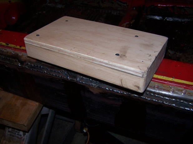
Posted by: Spoke Jul 18 2009, 10:01 AM
I ground down the flange for the tailshift boot. I have a flange from a sideshift boot to weld into place.
Attached image(s)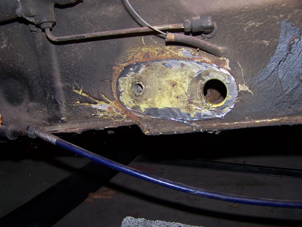
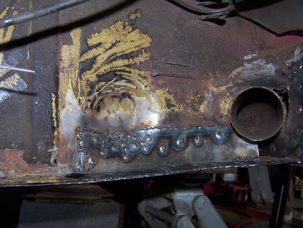
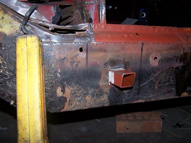
Posted by: Spoke Jul 18 2009, 10:06 AM
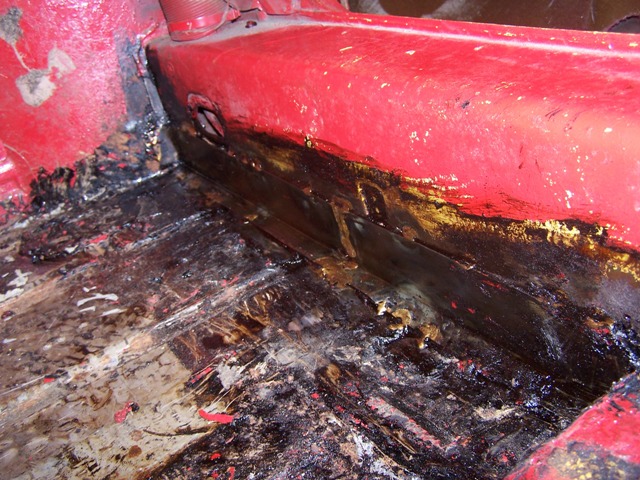
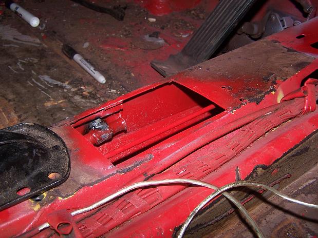
Ground off the previously added web and original web. The previously added web was covering a bit of rust through. 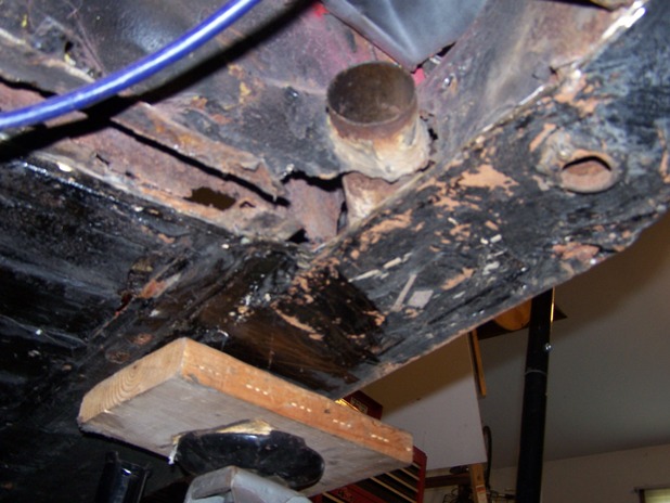
Here's a better shot of the rust around the heater tube. The plate on the bottom runs the entire length of the long and is now the bottom of the long. Between the heater tube and the engine mount, the bottom plate is not attached on the inside to the original vertical section of the long. This will be fixed now.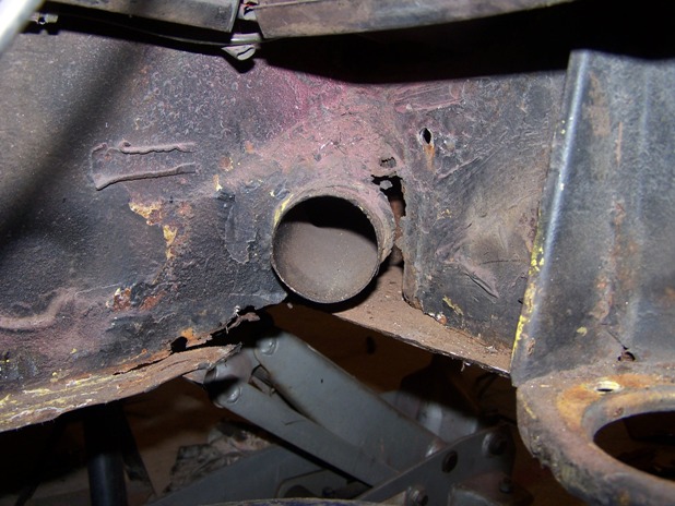
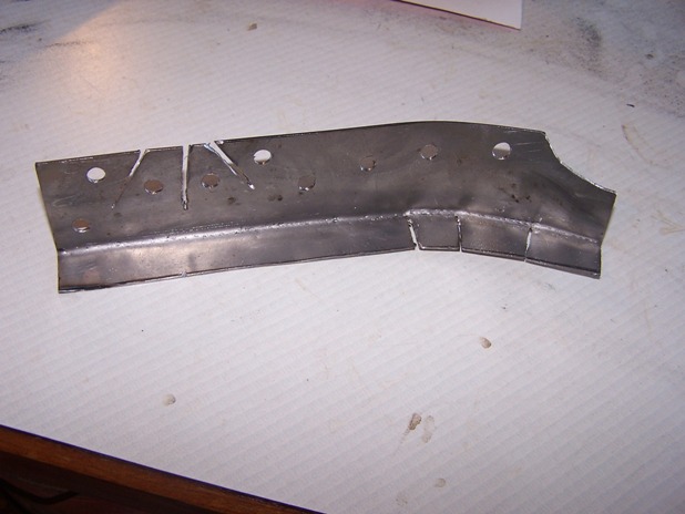
Posted by: Spoke Jul 20 2009, 10:38 PM
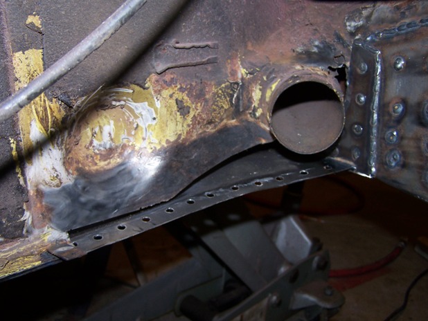
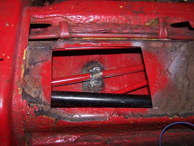
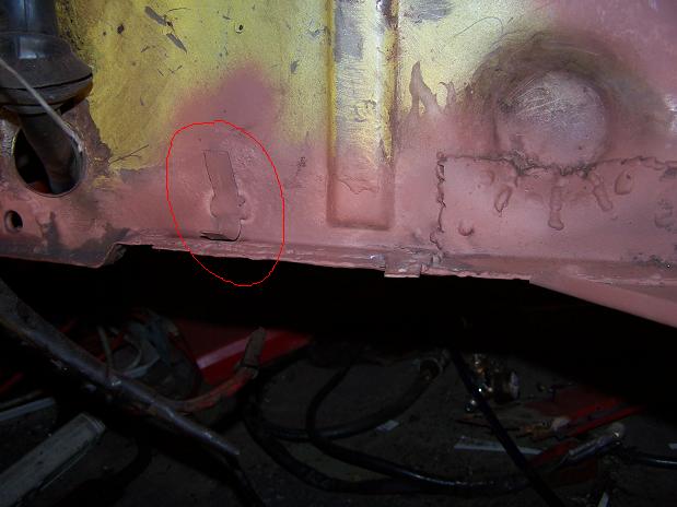
This patch will join the bottom long plate to the original vertical long. It will go from the engine mount to just inside the cabin on the inside. The little plate will strengthen the long as it passes below the heater tube.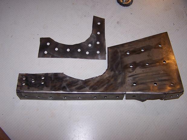
The patch & its stiffener are ready for mounting.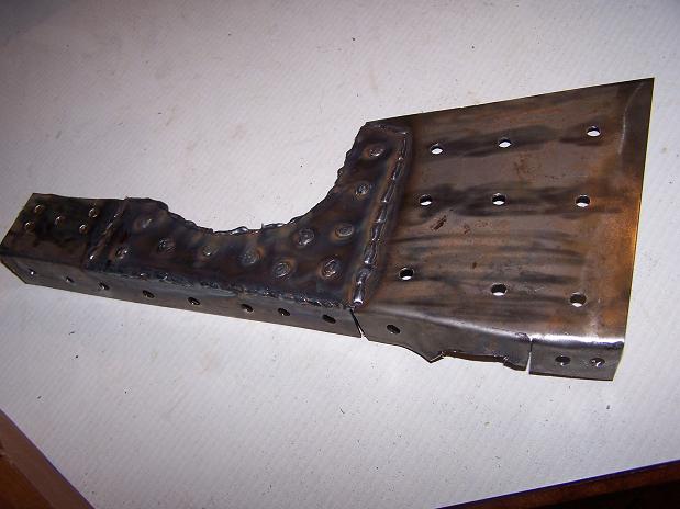
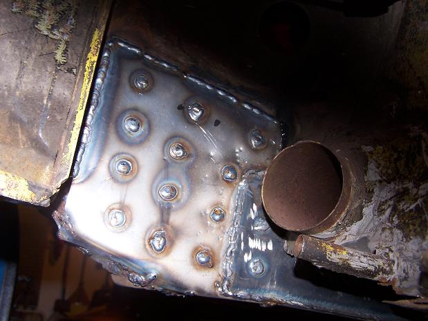
Posted by: Spoke Jul 20 2009, 10:44 PM
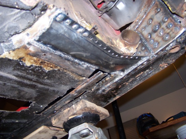
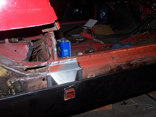
The patch is now welded in place. Just the front tip is visible from the cabin. 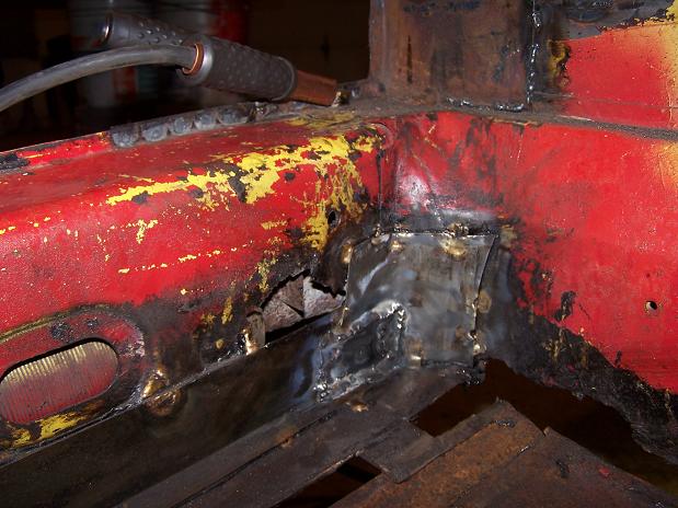
And the bottom view. I had the car on its wheels so the long was stressed as it is normally. I welded a hole on one side, then let the piece cool, then another hole on the other side so not to tweak the patch.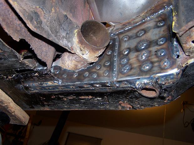
Posted by: Spoke Jul 20 2009, 10:48 PM
Also got the sideshift cover flange welded on.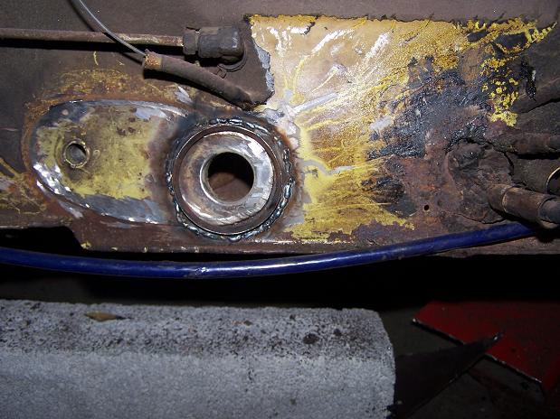
The boot fits fine.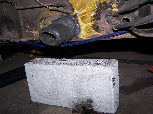
Posted by: Spoke Jul 22 2009, 11:20 PM
Got the back of the passenger floor patch done tonight. Welded this one from under the car which is a load of fun. The hardest part of this job is not the rust but all the tar put on the car on the bottom and in the cabin.
Also some of the existing patches were braised on and that stuff seems to explode when hit with the welder.
Next up is a patch for the bottom of the firewall. This one will likely be 2 parts: one on the flat part of the firewall and one under and around the heater tube.
Attached image(s)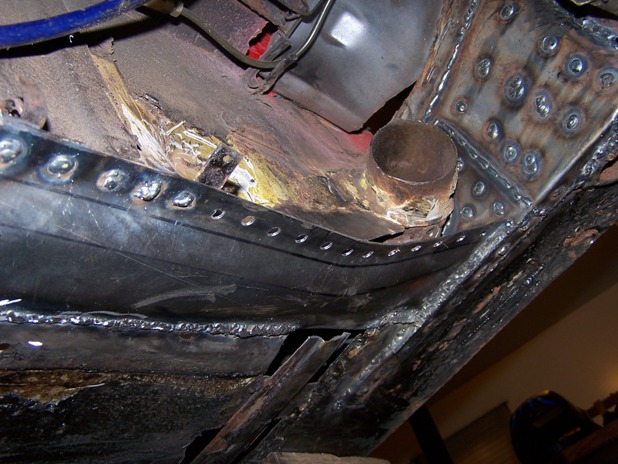
Posted by: FourBlades Jul 23 2009, 09:48 AM
Those are nice looking repairs.
Should be nice and strong.
Keep the pictures coming... 
John
Posted by: Spoke Jul 25 2009, 10:32 AM
Cleaned up the firewall around the heater tube. I'll use 2 pieces to go around the tube. The first piece has holes for spot welding as well as all edges are seam welded.
My welding still sucks but I am much more confident in my methods.
Attached image(s)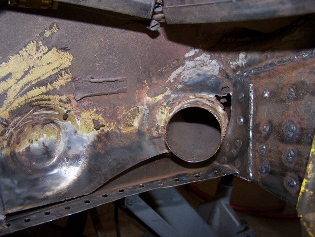
Posted by: Spoke Jul 25 2009, 10:39 AM
The 2nd piece around the heater tube is now in. I ground down some of the welds. Now I'm ready for seam sealer and primer to protect the metal.
Attached image(s)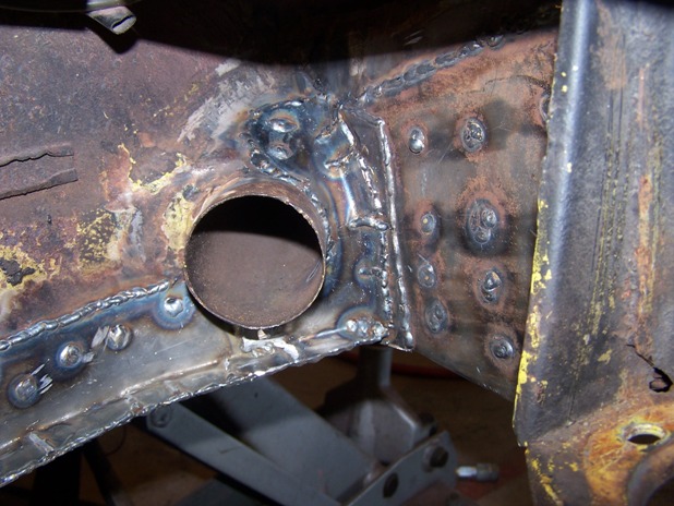

Posted by: Spoke Jul 25 2009, 07:46 PM
Patched the holes in the floor, inner firewall, and one on the inner long. Still need to do a rib near the long, make a seat bracket for the stationary passenger seat and patch the passenger crossmember.
Attached image(s)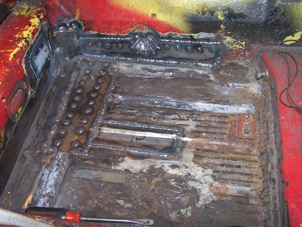
Posted by: Spoke Jul 26 2009, 04:26 PM
Last of the patches for the passenger side seat area. After a long time of losing weight via rust, my car is gaining weight.
These 2 pieces are for the crossmember and the right seat brace.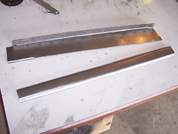
Crossmember is now finished.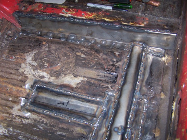
I welded the bolts to hold the stationary passenger seat before welding the seat brace in place.
Check out the little patch on the inner long. It is the cut-out for the front heater tube from Engman's inner long kit. No need to cut a piece out when this one fits just right.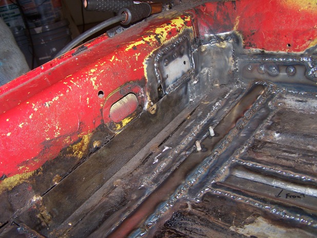
Posted by: Spoke Sep 11 2009, 07:15 PM
I'm ready to install new jack posts but it seems that the jack post sticks out quite a bit from the rocker panel. The panel is bowed in about 1/2 inch but another 3/4 inch will still stick out. The long has been repaired and is out further than the original but I wouldn't think the remade long would be over an inch further out than the original long.
Attached image(s)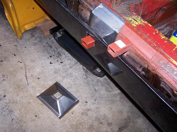
Posted by: FourBlades Sep 11 2009, 09:09 PM
Your car is really coming along. You jack tube sticks out because
of the way your long was repaired. The stock metal is two layers
thick where the tube goes through. The innermost layer bows into
the long by an inch or more. The next layer is the outer long
which is vertical and has a hole in it that the jack tube passes
through.
You either need to cut a hole in your long and stick the tube
in and weld it or shorten the tube and weld it to your repaired long.
This may be weaker than stock, if your repaired long is two layers
of good metal it may work ok.
A little hard to explain in words, if you look at some of the other
rusto threads you can see what I mean.
John
Posted by: Spoke Sep 11 2009, 09:15 PM
Here's one of the other things I've been taking care instead of working on the 914 of which also includes:
o Painting and repairing table & chairs for my daughter
o Installing tile backsplash in the kitchen
o Moving my daughter into her apartment in Pittsburgh.
o Moving my younger daughter into her apartment at school.
Oh yeah, these are the front rotors from my A6.
Note to self: "ALWAYS lubricate the slides on disk calipers when changing rotors/pads". The right side caliper froze on its slides and caused the inside pad to wear to nothing, thus destroying the rotor.
Attached image(s)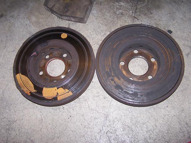
Posted by: Spoke Sep 11 2009, 09:20 PM
Your car is really coming along. You jack tube sticks out because
of the way your long was repaired. The stock metal is two layers
thick where the tube goes through. The innermost layer bows into
the long by an inch or more. The next layer is the outer long
which is vertical and has a hole in it that the jack tube passes
through.
You either need to cut a hole in your long and stick the tube
in and weld it or shorten the tube and weld it to your repaired long.
This may be weaker than stock, if your repaired long is two layers
of good metal it may work ok.
A little hard to explain in words, if you look at some of the other
rusto threads you can see what I mean.
John
Thanks, I knew the repaired long wasn't that much fatter than stock.
I think I will cut a hole then. If I shorten the tube, the jack may not seat all the way and could slip out.
In my best Dwight Shrute voice:
Question: How far does the tube stick out from the support? If I cut a hole and slide the tube in, then I need to know how far out the tube is from the support. I don't have a stock 914 to look at.......Who put my stapler in Jello? .....MICHAEL!!!!
Posted by: Spoke Sep 12 2009, 01:16 AM
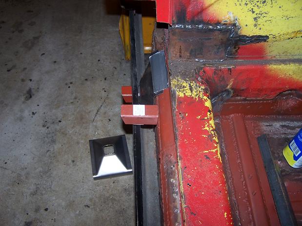
Mock up of jack tube using Rich Towle's location method of positioning the tube then painting the inside to mark it.
Cut hole and locate jack tube.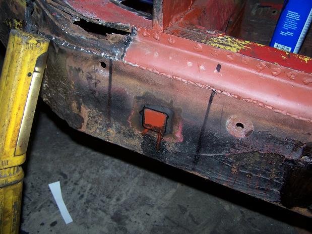
Posted by: Spoke Sep 12 2009, 01:20 AM
Jack plate looks good.
Length of jack tube is about right.
Jack tube cover from my 911 fits real nice. Time to weld the jack tube.
Attached image(s)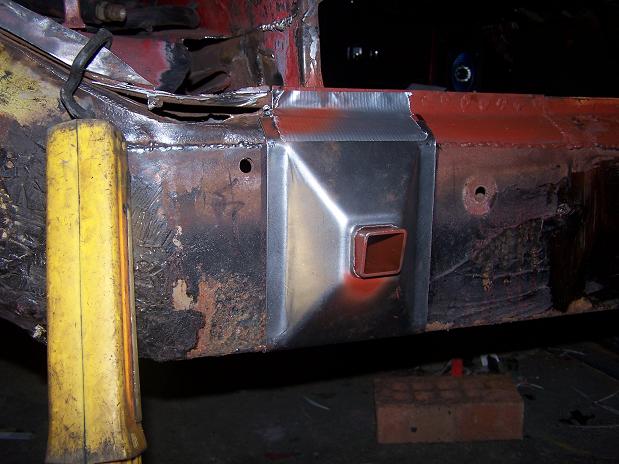
Posted by: Spoke Sep 12 2009, 05:34 AM
I used the little piece cut out from the long to seal up the jack tube so no moisture gets inside.
The jack tube is welded to the long.
Attached image(s)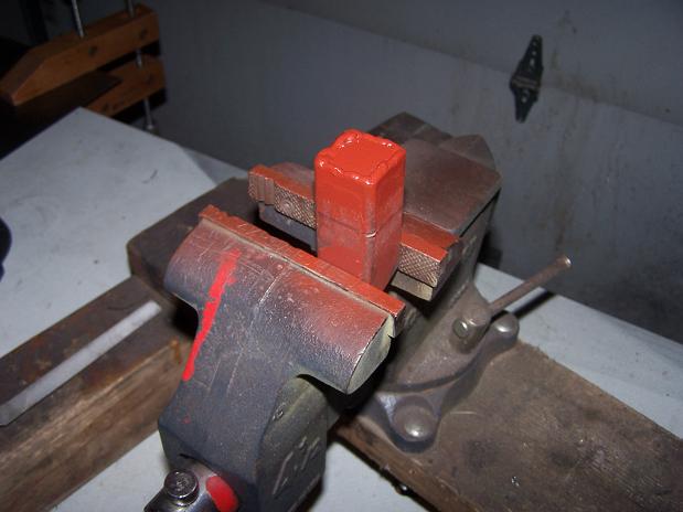
Posted by: Spoke Sep 13 2009, 02:13 PM
One last hole in the longitudinal patched.
Engine tin piece is in too. Previous engine tin replacement didn't match up well with the hell hole and firewall.
Attached image(s)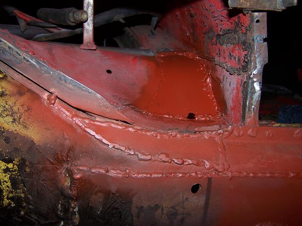
Posted by: Spoke Sep 13 2009, 02:33 PM
I have a metal bar sitting around so I thought I would try to strengthen the long by weliding the bar into the top of the long.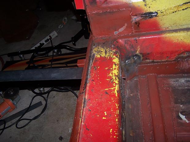
Added 2 more bars under the hell hole.
Bars are cut and welded in. Don't know if this will help the rigidity of the long but it's easy to do.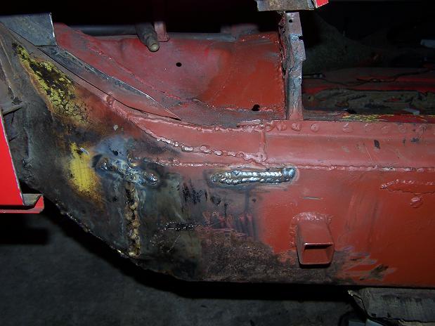
Posted by: Spoke Sep 13 2009, 09:51 PM
Put a couple more steel bar supports in the long.
Cleaned up all the brushed-on tar on the outside of the long and primed it. Looks like a blank canvas to me.
Attached image(s)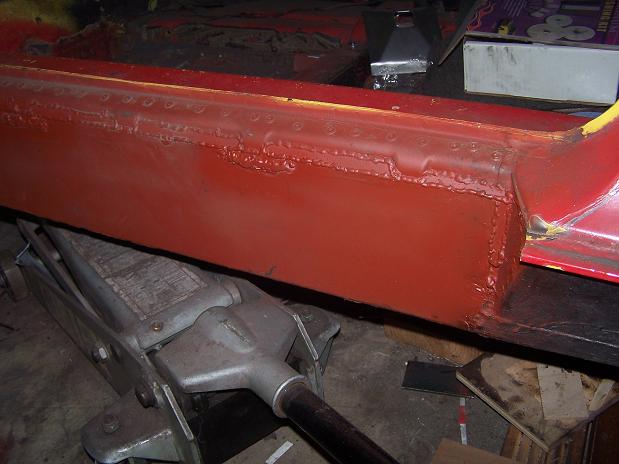
Posted by: Spoke Sep 14 2009, 05:57 AM
Jack support plate ready for welding.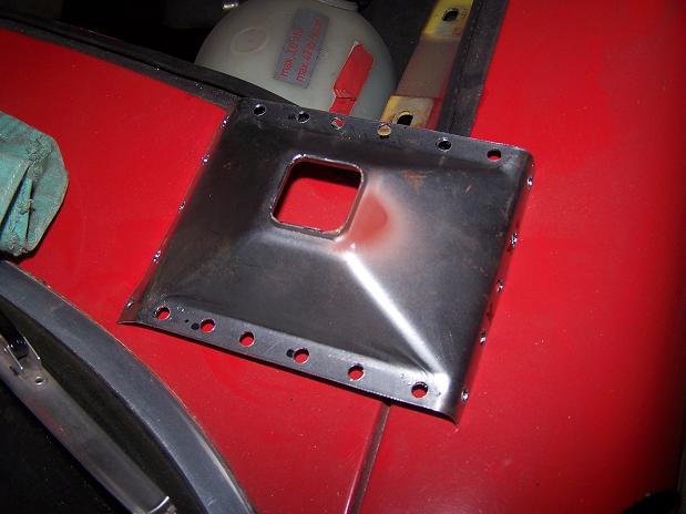
Presto!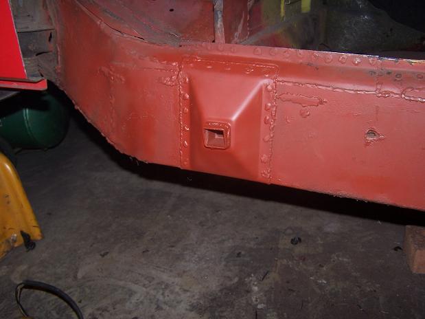
For the first time in probably 15 years, the car can be jacked up by the jack tube.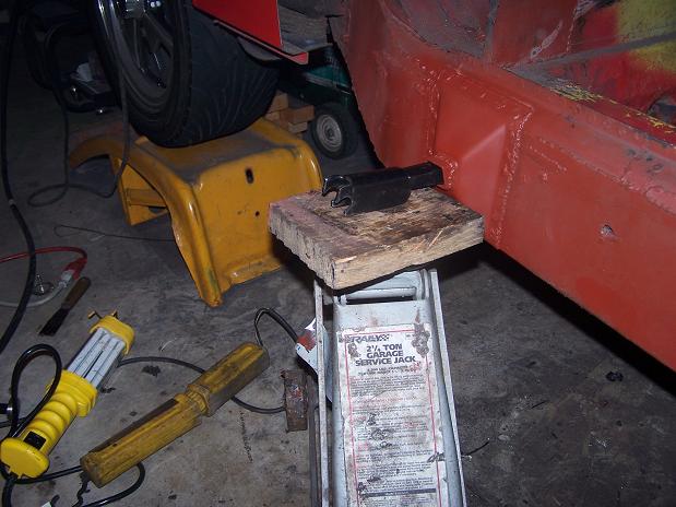
Posted by: Spoke Sep 21 2009, 08:54 PM
After some deliberation, I decided to investigate what is under the outside suspension pickup. There used to be more metal under there.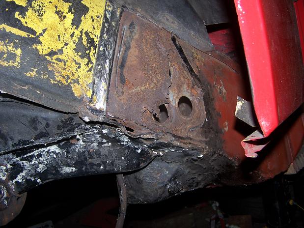
There is still some metal left on the pickup. I'll build up with new steel what has thinned out. 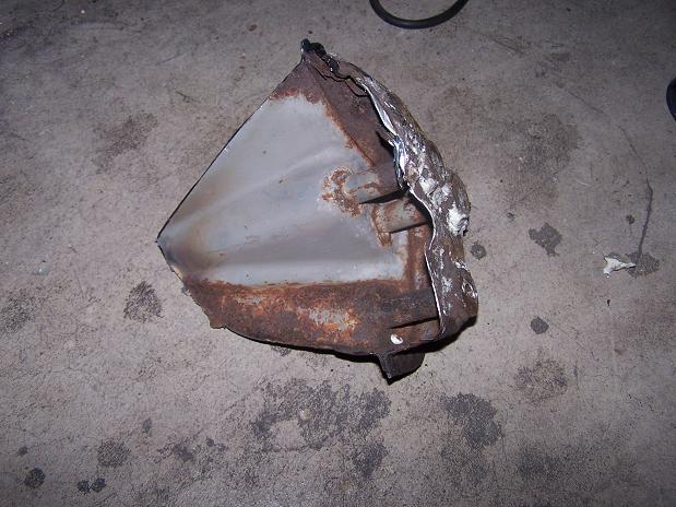
Posted by: Spoke Sep 22 2009, 05:44 AM
Cleaned back to good metal and patched. That looks better.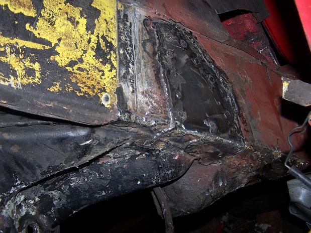
Home made clamshell ready to be welded in place. This will go from above the suspension pickup all the way to the jack support.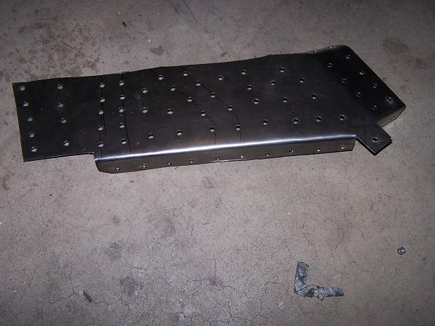
Posted by: Spoke Sep 24 2009, 10:08 PM
The long is ready for the support plate. The gray weld-through primer.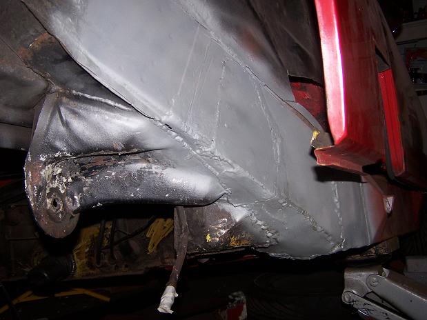
Posted by: Spoke Sep 24 2009, 10:12 PM
The support plate is welded in. Gray weld-through primer is on where the suspension pickup will be welded on.
Attached image(s)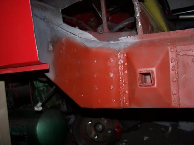
Posted by: Spoke Sep 24 2009, 10:51 PM
What to do if your nuts are too small: weld 2 together
The PO drilled out the existing bolts probably when they rusted and snapped.
So weld 2 nuts together and weld on top of the existing drilled-through sleeve.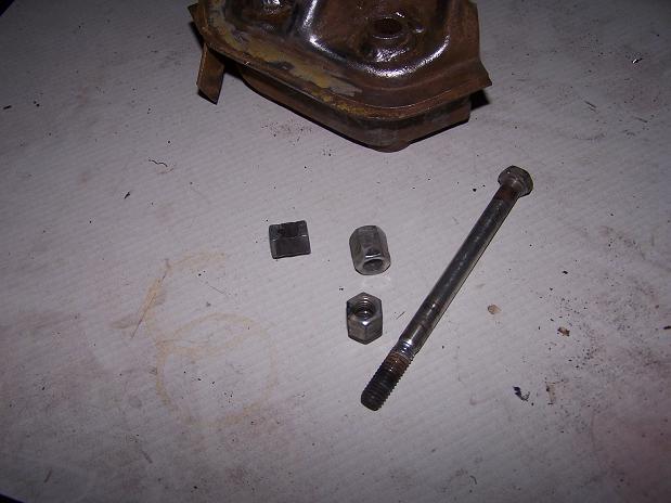
Nuts are welded on now. I just need to find something to cover the top of the nuts like the original plastic cap did.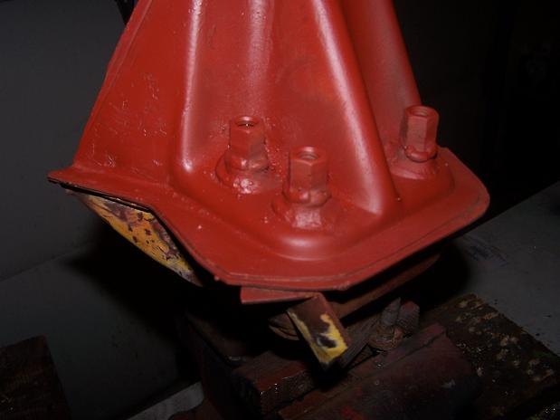
Posted by: Spoke Nov 16 2009, 04:05 AM
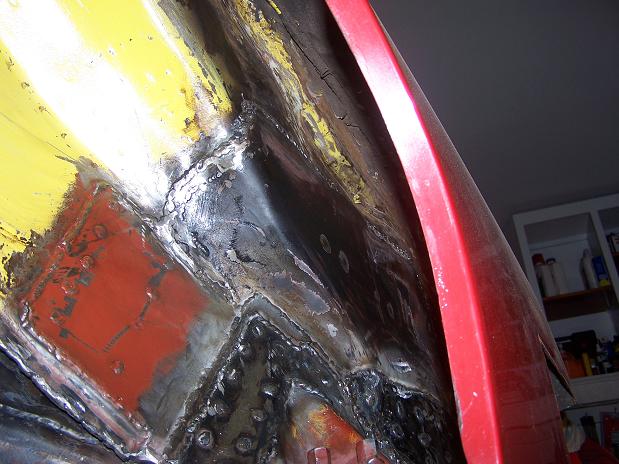
The suspension pick-up will be seam welded, then these 16 gauge plates will secure the pick-up on the long.
Attached image(s)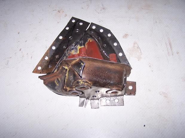
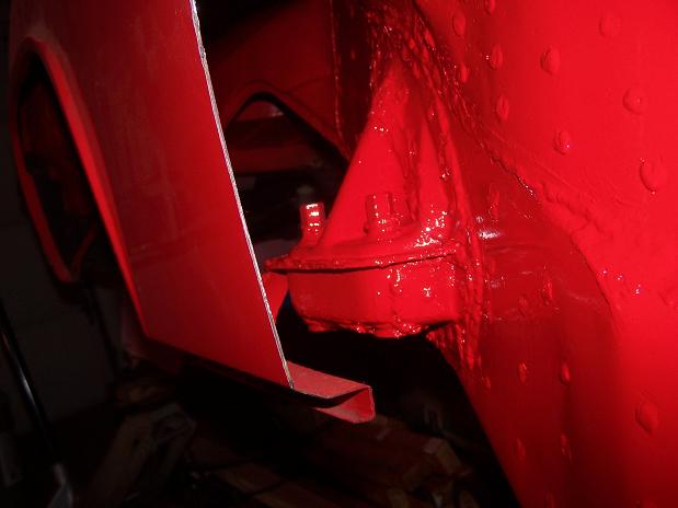
Posted by: Spoke Nov 16 2009, 04:17 AM
The suspension pick-up is welded on including the support plates.
The geometry of this corner is all messed up from the previous hell hole repair where the inside suspension pick-up was replaced and mounted about 3/4 of an inch too low.
This means for proper camber I needed almost 1 inch of shim plates. Since I would never be removing the inside suspensino pick-up, I decided to lower the outside suspension pick-up about 5/8 of an inch to minimize the stack of shims needed. This drop can be observed by looking at the support strap to the fender.
Attached image(s)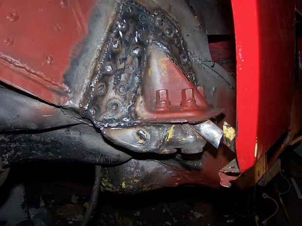
Posted by: Spoke Nov 16 2009, 04:23 AM
Finally time to patch up the hole looking into the hell hole. All work in the hole is done.
The replacement plate is 16 gauge.
Attached image(s)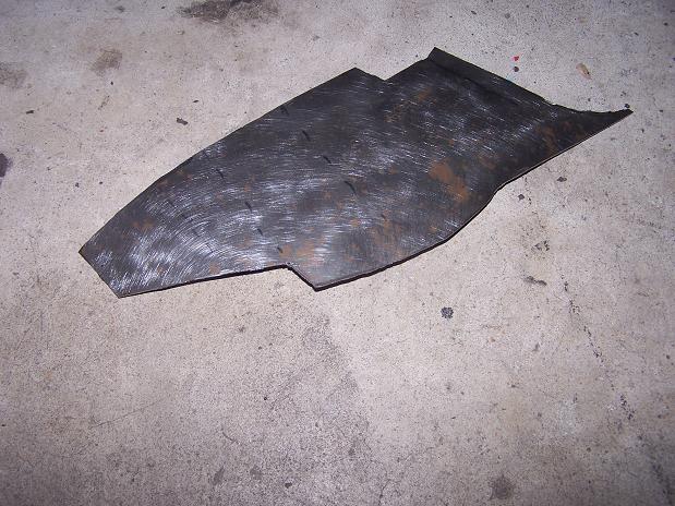
Posted by: Spoke Nov 16 2009, 05:03 AM
Support plates between inner and outer suspension pick-ups are welded in. 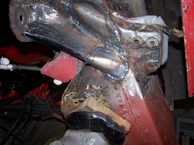
A PO repair to the inner fender wall only seam welded the new wall from the inside. Now the replacement piece is welded from the outside as well.
Attached image(s)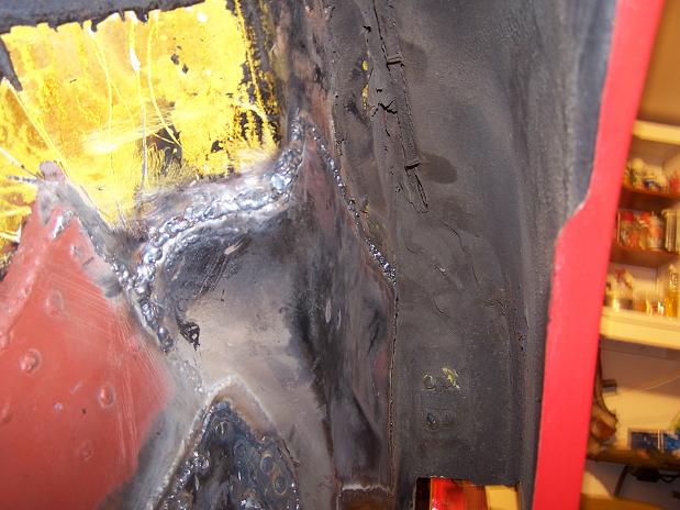
Posted by: veltror Nov 16 2009, 09:17 AM
Excellent thread, I thought mine was the only one with a rotten outside mount!!
Posted by: FourBlades Nov 16 2009, 09:19 AM
That is some great looking repair work! 
That should be good for 35 more years. I would seam seal all the welding
joints for extra corrosion protection. I would not grind the welds at all
because they will be covered up anyway.
John
Posted by: raw1298 Nov 16 2009, 12:14 PM
Awesome job 
 . Gets me pumped to finish mine!!
Posted by: Spoke Nov 21 2009, 08:43 AM
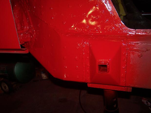
The original hell hole repair put that little patch on the firewall over the long. It's thin metal. I can't tell if 18 or 20 gauge. So I will put a support plate of 16 gauge over it.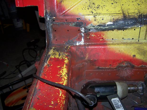
Same thing with the inner fender wall. Another plate of 16 gauge will cover this area although it has a 2nd purpose. The front part of the plate makes up the seam around the door where the weatherstipping goes. 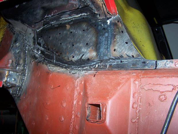
Plates ready to go.
Posted by: Spoke Nov 21 2009, 08:48 AM
And Presto! The 2 plates may add a little bit to the rigidity of the chassis.
Attached image(s)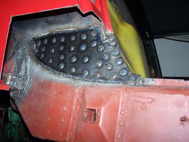
Posted by: my928s4 Nov 21 2009, 08:57 AM
Nice work, that looks like it will last a looooong time!.
Posted by: Spoke Nov 21 2009, 10:32 PM
The passenger side engine shelf is a replacement. Here's the backside of the replacement engine shelf folded up under the existing metal.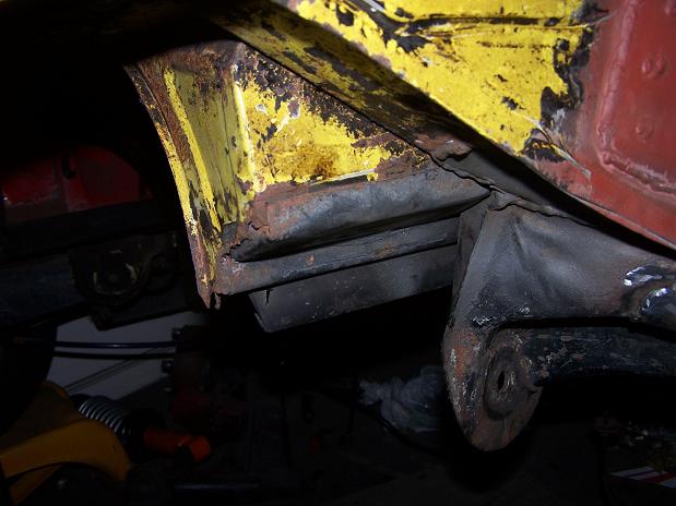
It's a lot more fun welding 16 gauge steel versus half rusted 18 or 20 gauge, whatever the engine tin is. Also seam welded the part of the long over the rear suspension.
That looks better.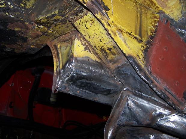
Posted by: Spoke Nov 23 2009, 05:41 AM
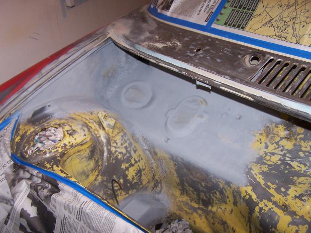
Prepping for paint. I either have a red car or a yellow car painted red.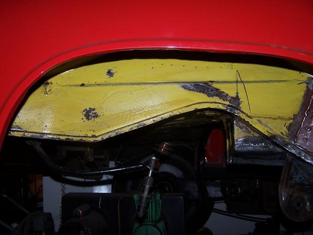
The wrinkled inner fender near the rear is where the damage was from the rear end accident.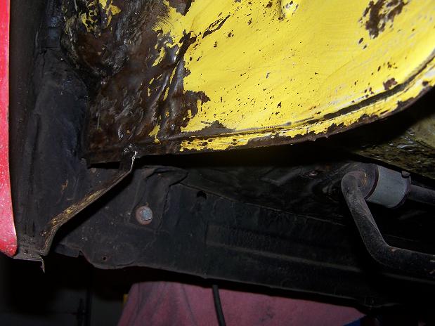
Posted by: Spoke Nov 23 2009, 07:39 PM
Primer going on now. Just painting the inner fender and bottom of the trunk floor around the shock. I'm only painting the areas that I am working on. I'm trying to avoid the "While I'm in there" syndrom. At least this corner will look good...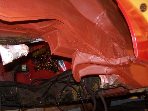
The wrinkles and surgery from the accident repair are noticible in this pic.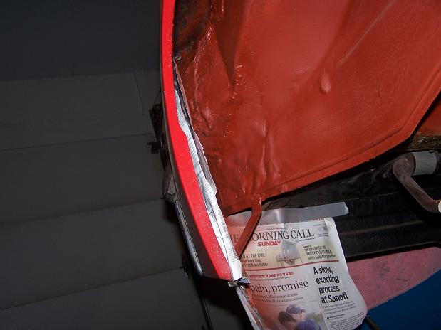
I'll paint the rest of the trunk floor when I turn the car around in the garage and work on the driver's side.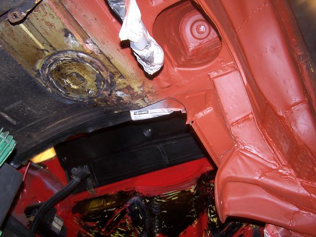
Compare this pic with the before where I stuck a putty knife through the rusted out metal.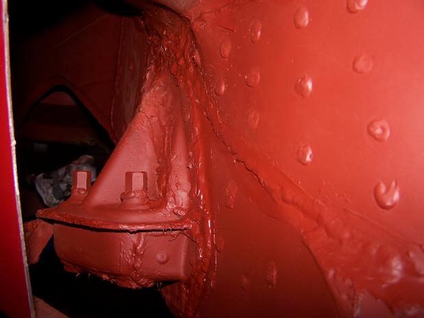
The area in question. Check out the jackstand party under the car. Only one is carrying weight right now. I usually have the floor jack under the long also.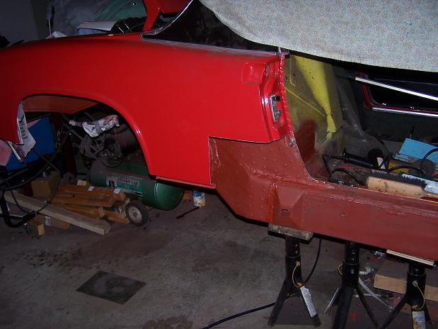
Posted by: Spoke Nov 25 2009, 11:38 PM
Had paint on then decided to fit the swing arm mount and had to make some clearance. This is the consequence of adding plate after plate onto the long.
Attached image(s)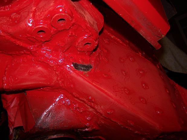
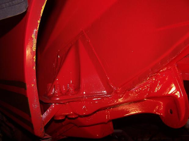
Posted by: Spoke Nov 25 2009, 11:44 PM
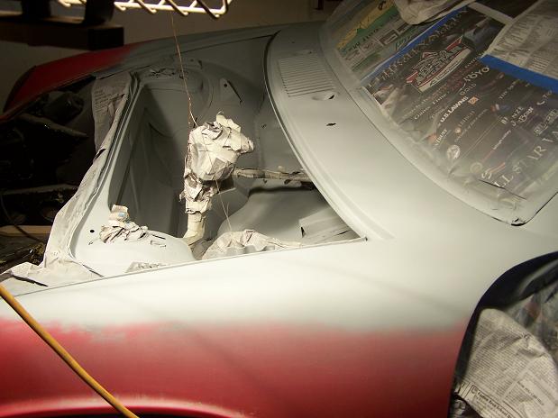
Got the paint finished tonight. Feels like I'm painting the outside of the car. Most of this work will never be seen once the fender is back together.
Attached image(s)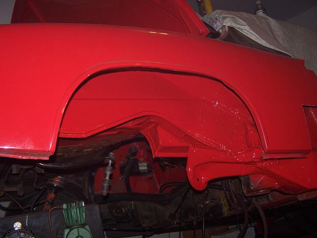
Posted by: Spoke Nov 30 2009, 12:05 AM
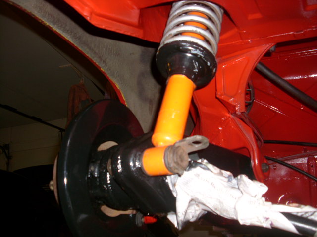
Putting the rear suspension back on. Had to spruce everything up with a coat of paint.
The garage must be relatively dry since the rotor is still shiny after sitting in the garage for over a year. 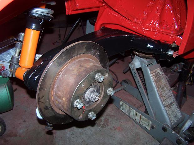
I checked the runout on the rotor. Not bad but not as good as I would like. The hub had a good bit of rust when I took off the original rotor and I never got the new rotor seated right and it always had some runout. I added a little 0.005 thick shim between the rotor and hub on the low side and it virtually cured all the runout.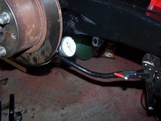
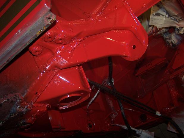
Posted by: Spoke Nov 30 2009, 12:10 AM
Caliper on.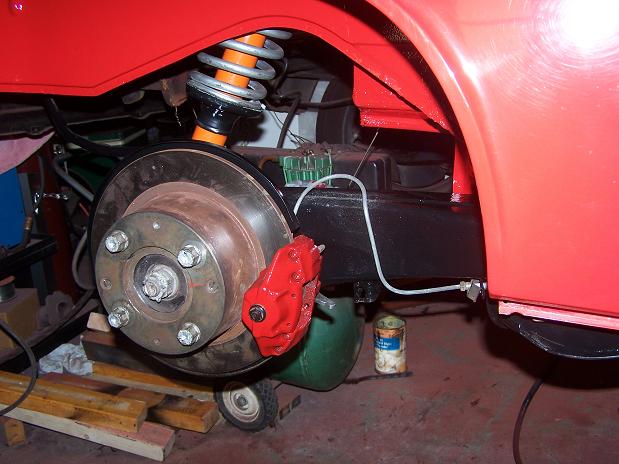
I had plenty of clearance between the suspension mount and the frame.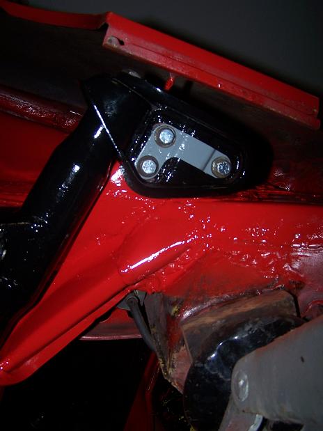
Posted by: Spoke Dec 2 2009, 08:19 PM
I finally got the car turned around in the garage so the driver's side is accessible.
Jobs in front of me right now:
Pull all the carpeting out of the driver's side interior.
Repair clutch tube and firewall.
Remove and repair rust holes around the driver side triangle plate and floor.
Clean up all the tar and undercoating in the engine compartment and paint
Remove driver rear suspension for painting and check for rust on the suspension console.
Repair driver side outer long (pictures coming)
I bought the car in Oct 2003 and this is the first time I've removed the driver side rocker panel. There was about 5 LB of gravel hiding in the rocker panel.
Attached image(s)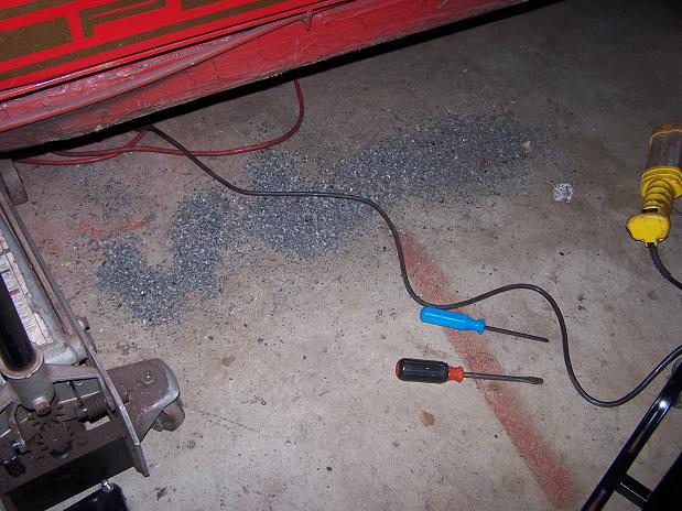
Posted by: Spoke Dec 2 2009, 08:37 PM
This side was also repaired like the passenger side with a big plate of steel and wrapped around the bottom of the long. That is a big hole in the long and just above it is a piece of tinfoil which I think was used to hold bondo on when the fender was repaired.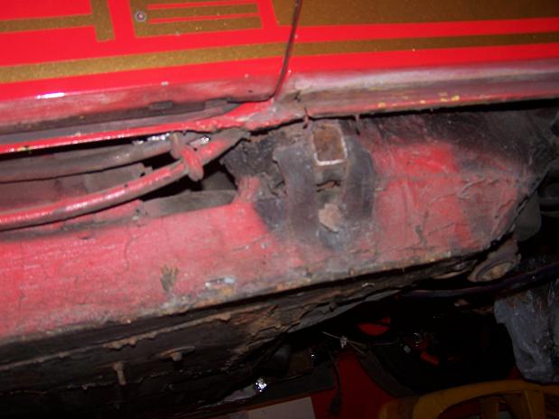
WTF half-assed repair is this on the jack point. It is very flexible and basically unusable. The top of the jack tube support plate is still there but the bottom has rusted away.
The gas tank vent hoses have some sort of grommet on them. Where would these grommets go?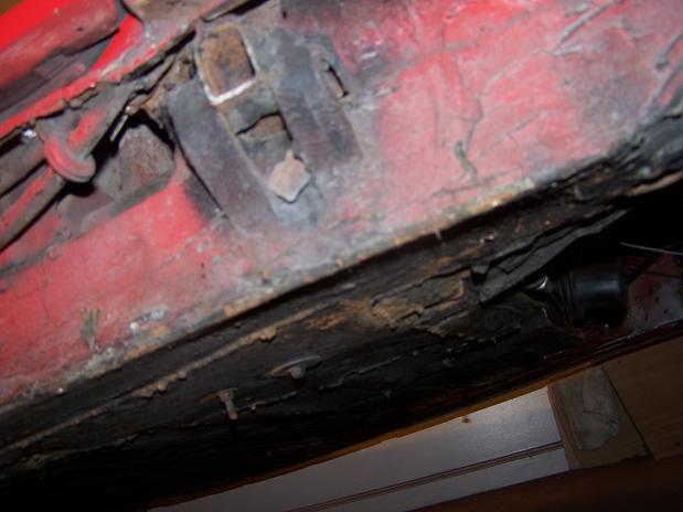
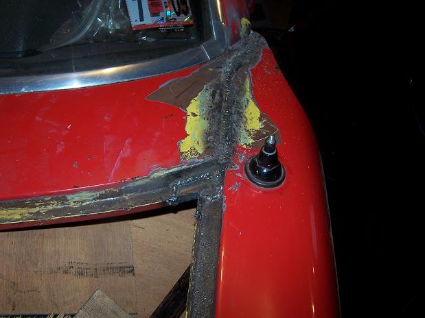
Close-up of the hole. Looks like I'll be taking off the sill plate and cutting the corner of the fender off to get access to the jack point.
However, the long at this point is relatively rigid so I will postpone the long corrective surgery until after the engine is back in. This way I can get the car on the road and as the long is repaired, I will have the correct pressure on the long to make sure the body dimensions don't change.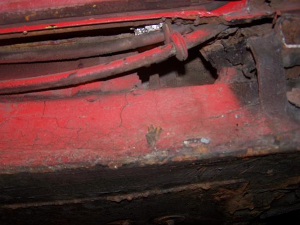
Posted by: watsonrx13 Dec 3 2009, 07:07 PM
The grommets go on the missing triangle underneath the sill...
http://www.tampabay914.com/pics/orig/91420040215_37_org.jpg
Keep up the good work...
-- Rob
Posted by: Spoke Dec 4 2009, 01:49 AM
Thanks for the photo Rob.
I think I'm missing part of the bulkhead behind the front wheels. Can I get replacement metal for this or must I fab it myself?
Attached image(s)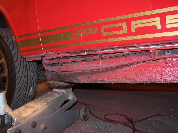
Posted by: Spoke Dec 5 2009, 11:06 AM
What! Another rust through hole on the drivers side? And rusted out inner long? The screwdriver is poking out the bottom of the car.
What a shock!
It appears the entire inner long is rusted up to the driver's cross brace. 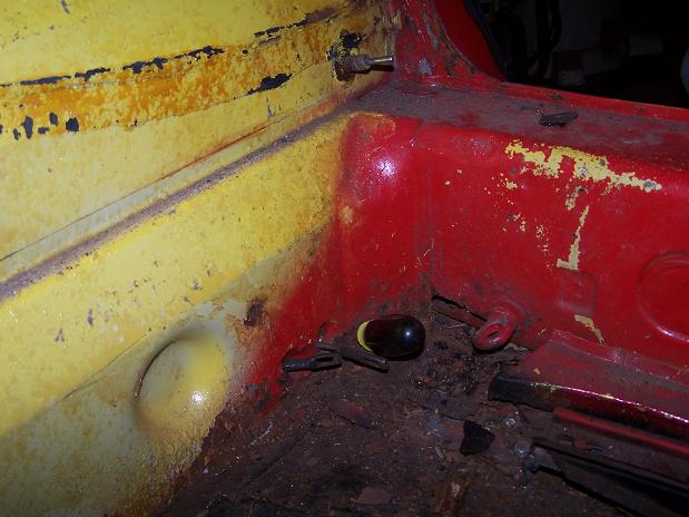
The corner of the floor has been replaced with a flat piece of metal. Note the Ace Hardware seat mounts...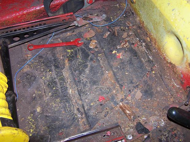
Found this piece of brown/white wire under the sound pad. Now that's my kind of electrical circuit. It comes from nowhere and goes nowhere. This may be difficult to get working again. 
Posted by: Spoke Dec 5 2009, 11:15 AM
Post Whore.
The World timed out again and doubled my post. Sorry.
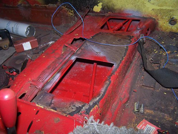
Posted by: Spoke Dec 5 2009, 04:18 PM
Here's the Ace Hardware seat pivot repair. Not pretty but it works. I'm not planning on changing this.
BTW, can you tell where I park my 911?
Attached image(s)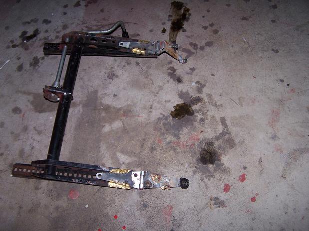
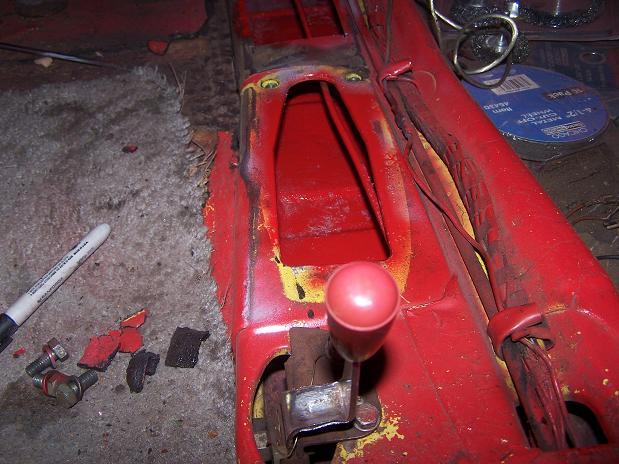
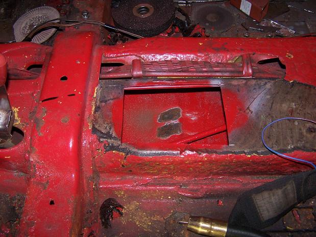
Posted by: Spoke Dec 5 2009, 04:22 PM
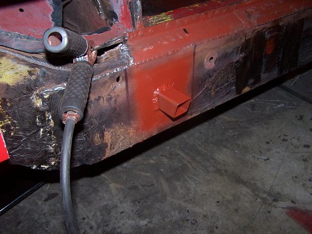
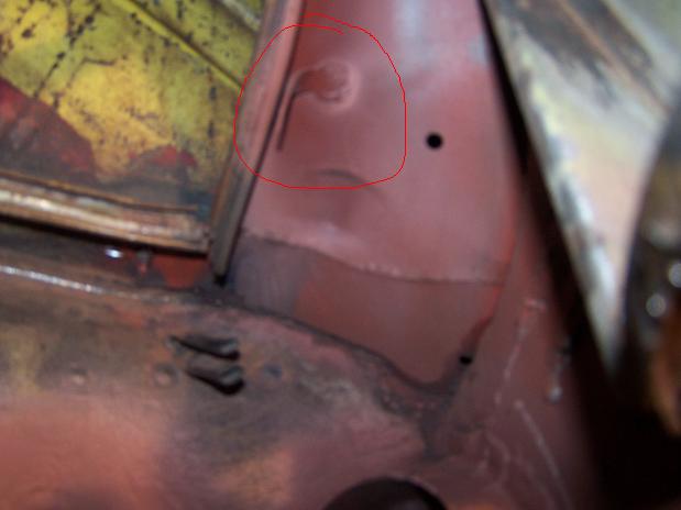
Here's the middle support. I guess the clutch tube goes where the red circle is, correct? There is a lot of stress if I put it where the circle is.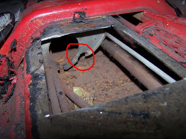
The original tab is still half attached to the side of the tunnel. Looks like someone tried to put a clamp on the tube. The extra clamp was not attached to anything although there are some holes in the side of the tunnel wall.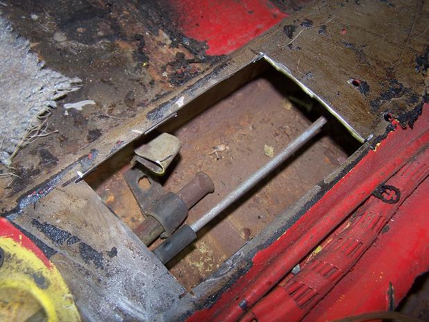
Posted by: sendjonathanmail Dec 5 2009, 09:19 PM
Hey man, did you use an airbrush when you painted inside the fender? What kind?
Posted by: my928s4 Dec 5 2009, 10:00 PM
Here's the Ace Hardware seat pivot repair. Not pretty but it works. I'm not planning on changing this.
OK that is pretty funny, I was thinking of the "build it on a budget" banner but "bodge it on a budget" is probably more appropriate.
That driver side rocker looks scary.
Nice work, great pics too !
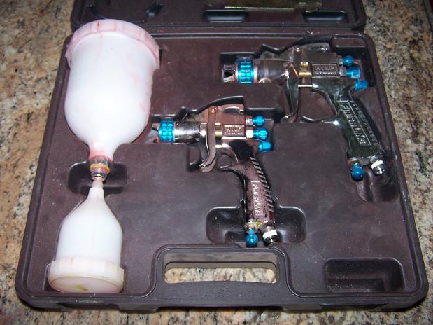
Posted by: Spoke Dec 6 2009, 05:47 AM
Hey man, did you use an airbrush when you painted inside the fender? What kind?
I used the small gun. I picked this DeVilbiss kit up at Eastwood.
Attached image(s)
Posted by: Spoke Dec 6 2009, 08:51 AM
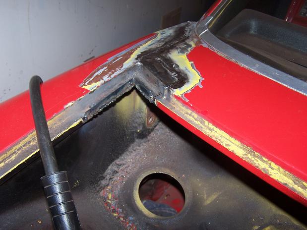
The clutch tube was repaired before as there is a bunch of weld material built up around the tube. The problem is the weaken-by-rust firewall around the tube ripped.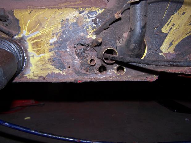
Made a template for a replacement piece. This piece will be quite detailed as it will have 3 holes; one for the tube and 2 for the fuel lines. I'll make the piece out of 14 ga to be sure there is enough strength. I knew my "Stop Walmart" signs would come in handy. 
To remove the tube, I had to make only one vertical cut to the left of the tube as the rest of the metal had already ripped.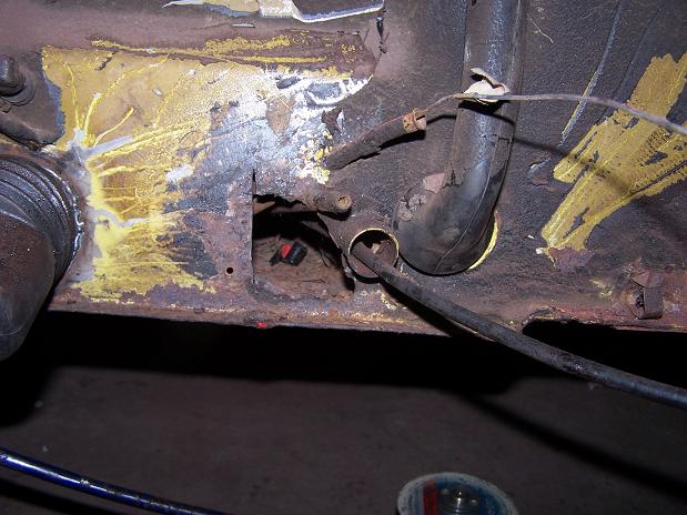
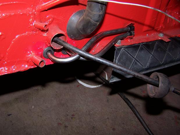
Posted by: Spoke Dec 6 2009, 10:13 AM
So what shape should the clutch tube have? This one looks like it has a jog around the shifter.
Attached image(s)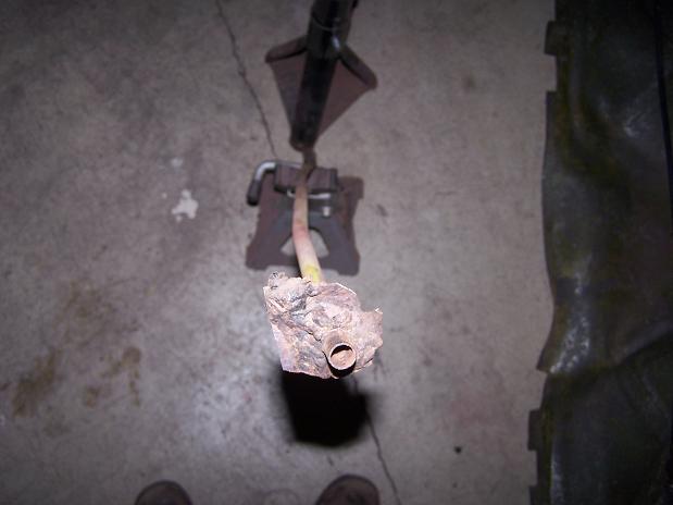
Posted by: Spoke Dec 6 2009, 07:36 PM
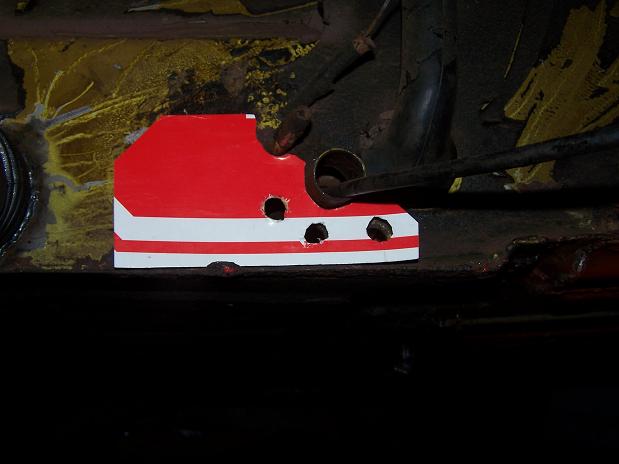
The plate for the firewall is completed and ready for welding. I will be overlaying the second piece on the first for more support. The 2 center holes are for the clutch tube. When doing a mock up with the side-shift engine bar, the top hole was too high and wasn't pointing towards the hole in the engine bar so I made a lower hole. See pics in the next post for different exit hole positions.
The little support plate will cover up the extra hole. I was too lazy to make another piece...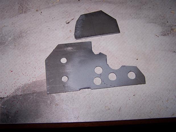
I straightened out the clutch tube and re-bent it to match the clutch tube shown in the classic clutch tube repair thread.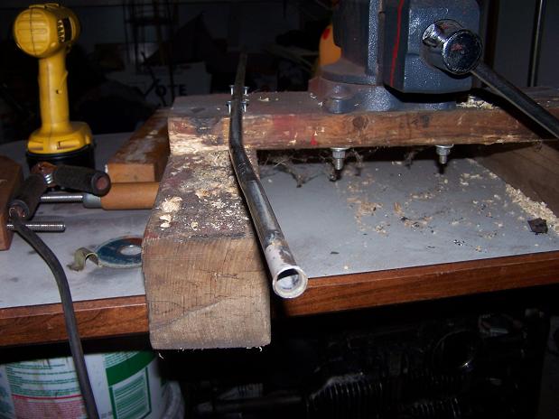
Posted by: Spoke Dec 6 2009, 07:40 PM
While studying the classic clutch tube repair thread, I noticed the 2 pics in the thread show 2 different exit locations for the clutch tube. One is higher than the other. My 71 had the high mounting but it didn't point towards the hole in the engine bar so I'm going with the lower exit position.
High exit position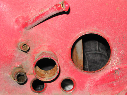
Low exit position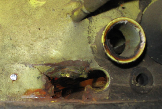
Posted by: Spoke Dec 6 2009, 10:10 PM
I made a bracket for the front of the tube. There wasn't much left from the old one. I'll weld this one on from the outside of the tunnel.
Attached image(s)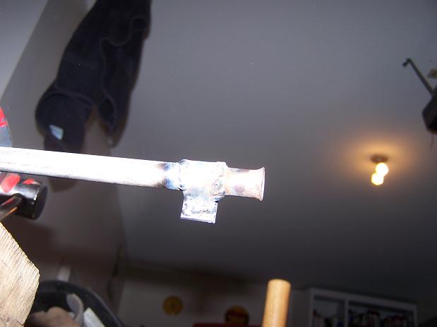
Posted by: Spoke Dec 9 2009, 01:20 AM
I used Duplicolor's Rust Fix to prepare the metal for paint. I scraped as much junk out as possible before painting. Looks nice. Too bad no one will see this once the interior is in place.
Attached image(s)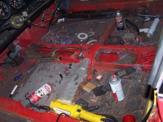
Posted by: Spoke Dec 9 2009, 01:22 AM
Got the tube all straightened out and then bent in the shape needed to fit properly. Sanded and painted it just to look nice even though no one will see it.
Attached image(s)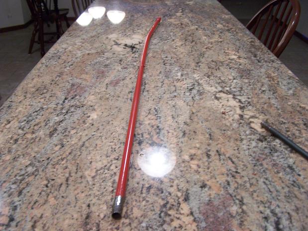
Posted by: Spoke Dec 9 2009, 01:24 AM
So I had to pull the 911 out of the garage to work on the 914 tonight. This is what I saw when I pulled it back in. Dammit. No midnight run though the township tonight. Tonight's ride will be about 20 feet back into the garage.
Attached image(s)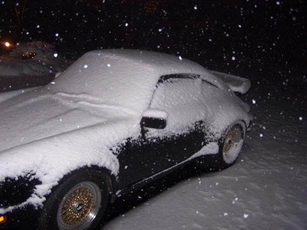
Posted by: Spoke Dec 10 2009, 10:28 PM
Getting ready to weld the clutch tube in. The front of the tube will be welded from the outside of the tunnel.
The center tab will be welded to the floor. I'm using the original front tab as the center tab.
Attached image(s)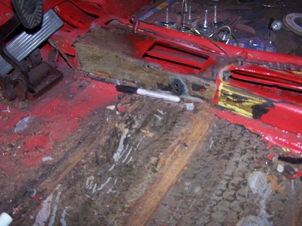
Posted by: Spoke Dec 10 2009, 10:35 PM
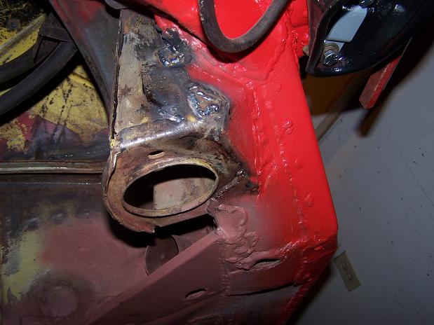
Finally welded the tube in. I made the front bracket from a leftover piece of 16 gauge steel. I'll clean up the welds, prime and paint.
The center tab just holds the tube in place. The firewall and the front bracket will provide all the support of the clutch cable.
Attached image(s)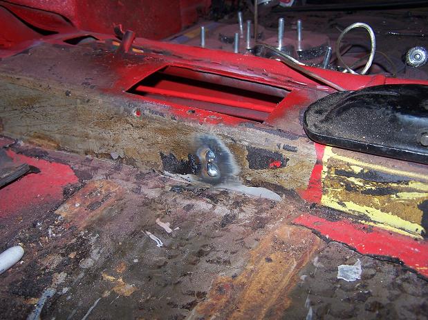
Posted by: Spoke Dec 10 2009, 10:40 PM
This plate is 2 plates, a large 14 gauge plate and a smaller backup 14 gauge plate. I don't think the clutch tube is going anywhere this time.
Attached image(s)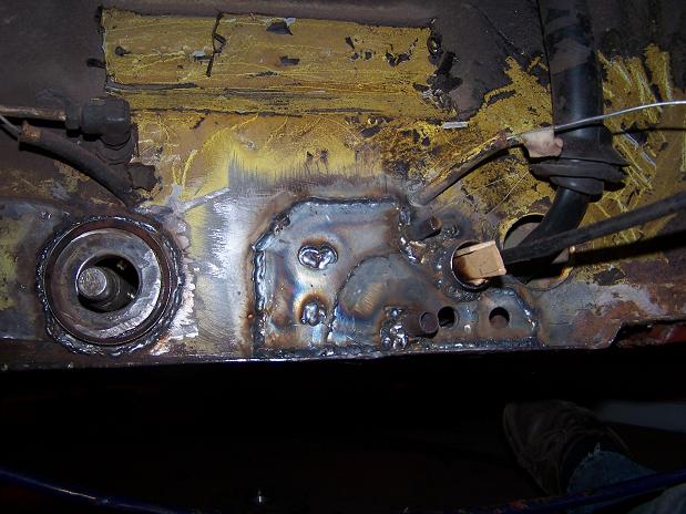
Posted by: Spoke Dec 19 2009, 10:26 PM
I didn't think the drivers side was as bad as the passenger side but this hole just seems to grow and grow. The triangle plate has just been cut off to investigate this little hole. 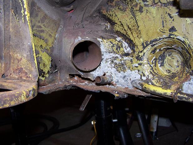
The putty knife is sticking through a hole in the floor from the inside of the cabin.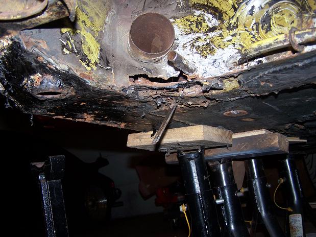
The condition of my 914 was undoubtedly affected by weather like this. We're supposed to get 4-8 inches today.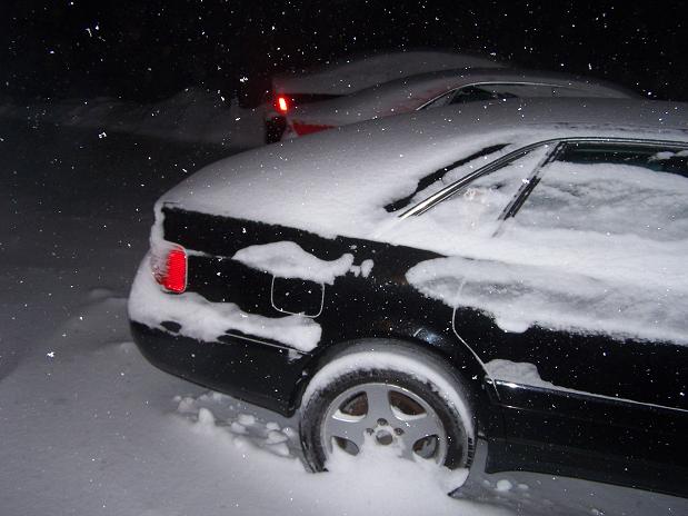
Posted by: Spoke Dec 19 2009, 10:37 PM
Started cutting out the bad stuff. All the rust on the floor was hiding inside the long. All this stuff was just loose in there. The seat belt bolt didn't have much holding it in place. I will make a piece to go on the inside of the long from the engine compartment to the interior.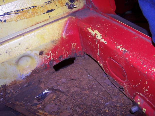
This part of the inner long is just as bad as the passenger side. I still have more cutting to do to clean this up. Then make some panels and weld in place.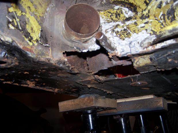
Posted by: silver74insocal Dec 19 2009, 11:46 PM
[
FI runners. Which is the left and which is the right?
[/quote]
the clips that are welded on for the fuel line go towards the front of the car..good luck
Posted by: Spoke Jan 16 2010, 04:29 PM
First piece to fab is the inside long. All final cutting is done for the piece.
The horizontal plate had been added by the last guy to replace a totally rusted out bottom of the long. It is 16 ga and the one piece wraps around the outside of the long going about 1/2 way up the outside. There is nothing left of the long on the bottom from in front of the jack tube support to where the bottom long curves upwards.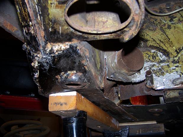
Yes, it's true, there is a jackstand party at Spoke's place. My jackstand and 3 of his buddies are all hanging around where men are working...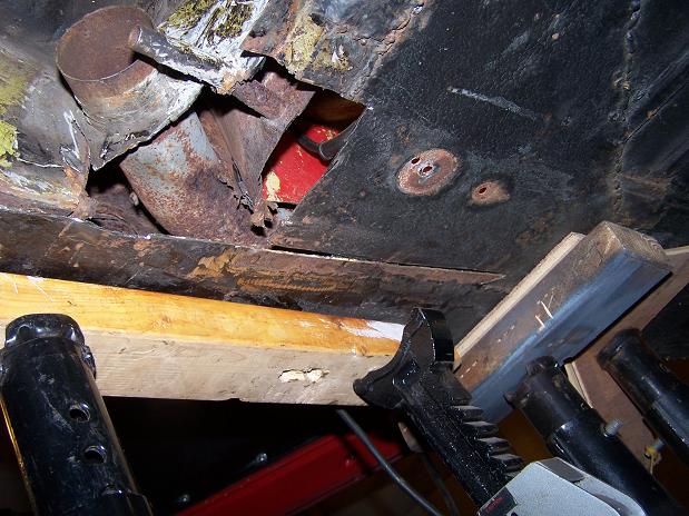
Inside view. The corner of the floor has already been replaced by a flat plate of 18 ga.
The little sliced hole is actually between the floor piece and long piece. The replacement part will slide right up in this cut and wrap around to the bottom horizontal piece.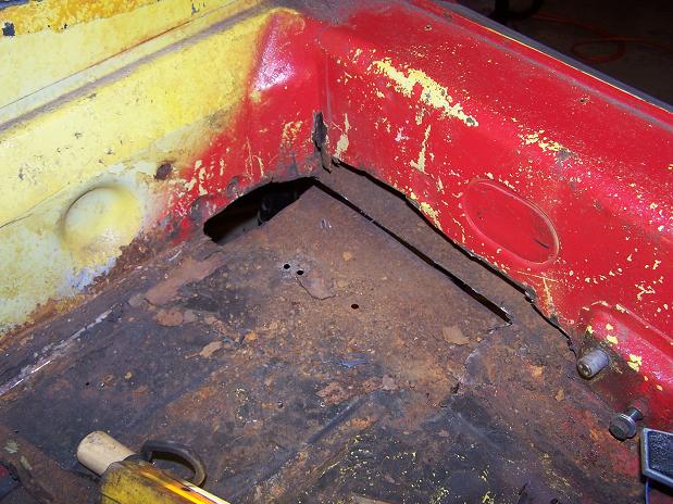
Posted by: Spoke Jan 17 2010, 03:49 PM
Well, no 914 work going on today. Focus today is the rear wheel bearing on my 911 turbo. This thing was singing to me when I bought the car last April and finally gave it up yesterday and refused to turn freely.
Quiz: Guess which rear caliper is from the 914 and which is from the 911 turbo.
(hint: the 914 is RED).
Attached image(s)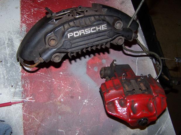
Posted by: Spoke Jan 22 2010, 08:20 PM
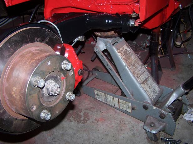
Well, I'm not working on the 914 but at least I'm working on a Porsche. Out comes the rear hub on the turbo with a hub puller. It took about 5 medium hits to get this out.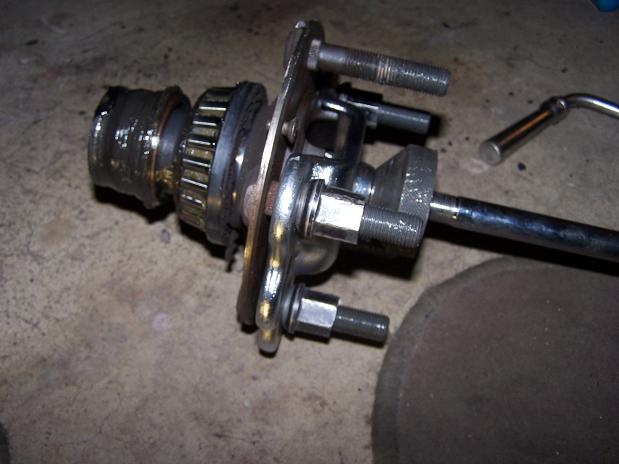
The inside bearing has lost its cage. All the bearing are huddled at the bottom of the race. 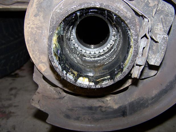
There are no bearings at the top of the race.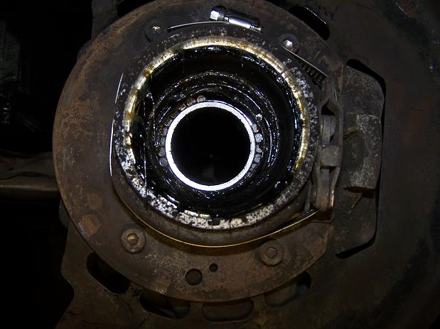
Posted by: Spoke Jan 22 2010, 09:44 PM
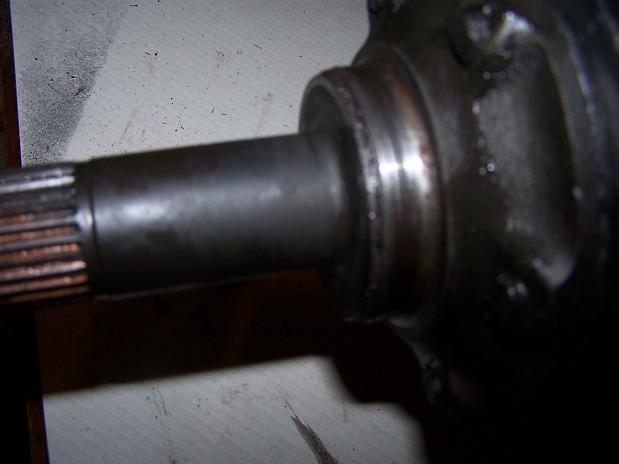
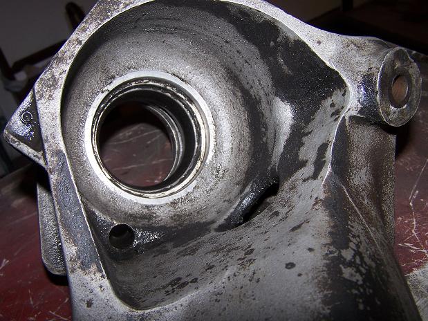
Calling the Cap'n: Does this rear drive look ok? The ledge for the grease seal is damaged on the outside. Is this terminal?
Attached image(s)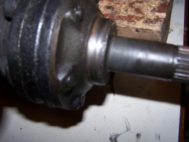
Posted by: Spoke Jan 24 2010, 12:15 PM
Still working on the 911. Trying to remove the rear swing arm and I can't figure out how to get a wrench between the frame and the tranny to secure the bolt.
Anyone have tips for getting a wrench on this?
Attached image(s)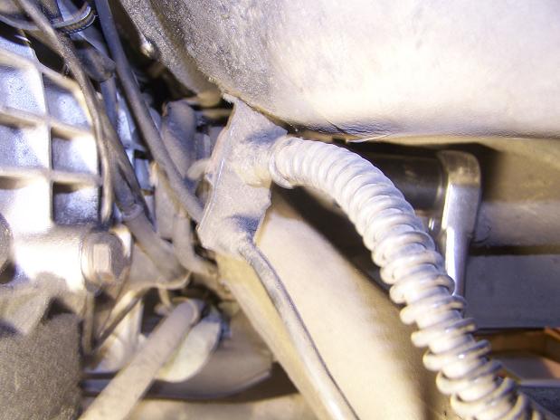
Posted by: Spoke Jan 30 2010, 02:39 PM
Still no 914 content. I finally got the inner swing arm bolt off by bending my wrench to fit around the tranny and secure the nut.
I've been struggling with the inside race on the hub. I tried a bearing separator but it did nothing. Even tried heat on it and the damn thing wouldn't budge.
After about 4 hours fuching with the separator, I got my Dremel tool and sliced the race, stuck a flat head screwdriver in the slot and gave it one hit with the hammer and its off.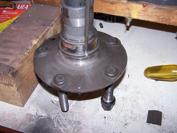
Posted by: Spoke Jan 31 2010, 08:19 AM
Still no 914 content.
Finally got the trailing arm off. The inboard bearing cage is gone. All the boys are present and accounted for but without the cage, there was chaos. 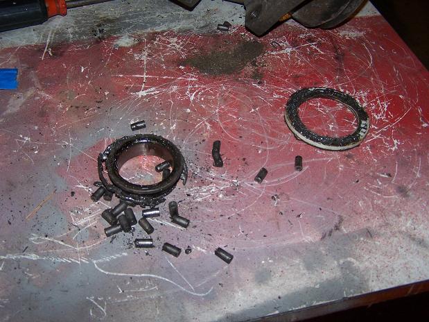
Nice and cleaned up.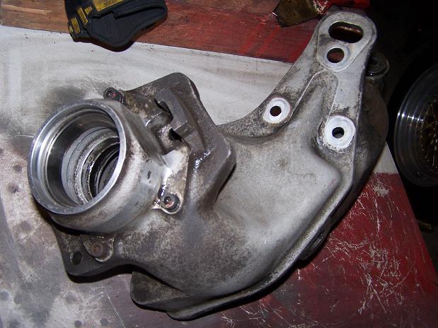
Procedure was to heat the arm really hot then remove the outer races. I'm lazy so I used my Dremel again and one hit with hammer and drift and the outboard outer race is out.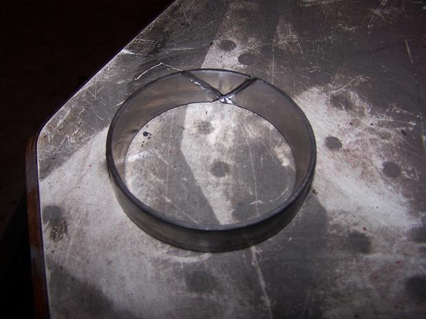
Negligible damage done to the trailing arm by the Dremel. Total time was about 15 minutes to get the outboard race off.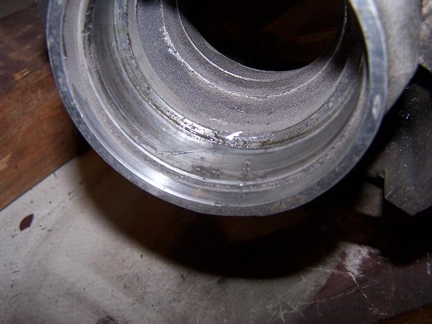
Posted by: Spoke Feb 10 2010, 06:47 AM
Got the 911 back together 

I couldn't press the hub onto the bearing so I took the hub & trailing arm to John at Mr. B's in Maxatawny, PA as he has extensive experience with Porsche, Audi, VW, Mercedes, etc., anything German and has built a 911 racecar before.
John did the work in less than 1 day. I hate to pay someone to do a job that I "wish" I could do but it was well worth it to have a knowledgeable guy do the pressing. Also had him make a new hard brake line to the caliper since the original was kinked.
There was an awesome brown 72 914 at Mr. B's. This thing was in perfect condition. The interior was perfect and no cracks on the dash.
Total cost of wheel bearing replacement:
$90 Bearing & seals
$90 ebrake shoes
$150 bearing press & custom hard brake line
$330 Total
The messed up rear drive that Cap'n Krusty gave me advice on was actually in pristine condition. When I finally went to clean it up, it turns out the damaged end was only hardened crud. Once cleaned up, it was in perfect condition. Thanks to the CAp'n for you advice. 
Posted by: Spoke Feb 10 2010, 07:02 AM
Back to my regularly scheduled 914 rustoration:
This piece will go on the driver side inner long.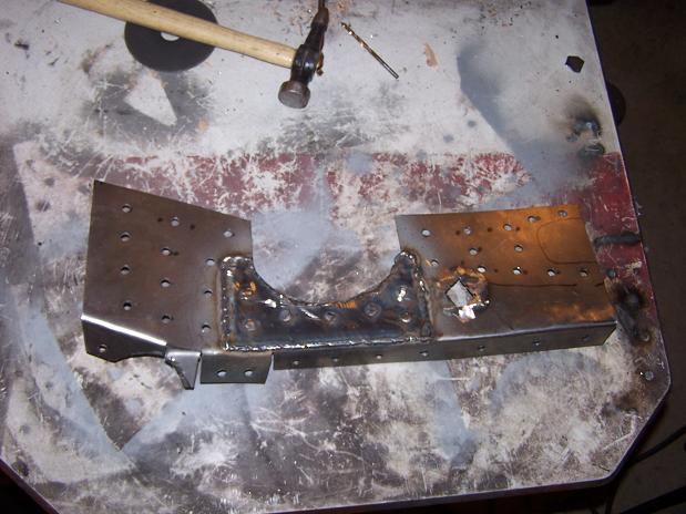
All welded in. The hole is for the seat belt mount. I will weld a bolt onto a piece of 14 gauge steel and weld the plate in place. Since I slid this piece up through a slice between the long bottom and the floor, I didn't want to cut a hole in the bottom long to make clearance for the bolt.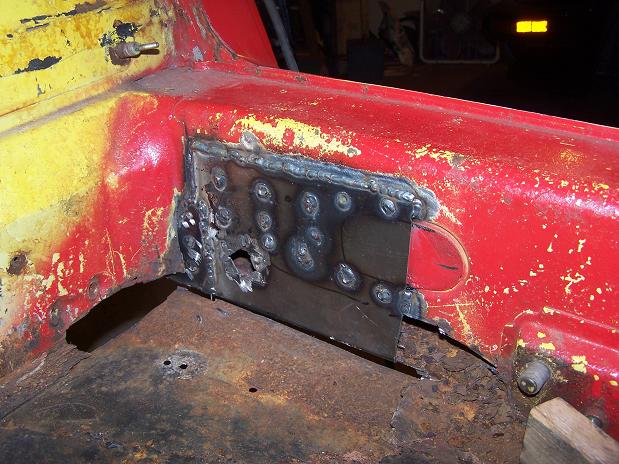
Posted by: Spoke Feb 10 2010, 09:22 PM
Piece for the floor out of 18ga.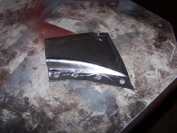
And welded in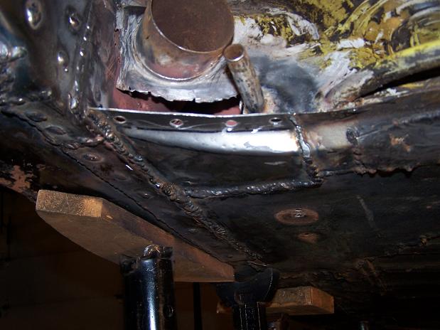
Welded up the existing floor to the new long piece.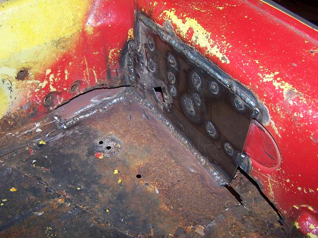
Posted by: Spoke Feb 10 2010, 09:25 PM
Engine firewall repair piece under the driver heater tube.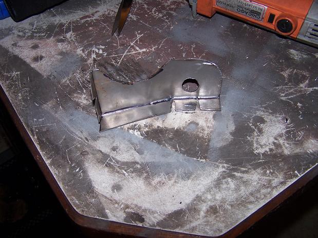
Welded in. Look Ma, no more rust holes in the engine compartment.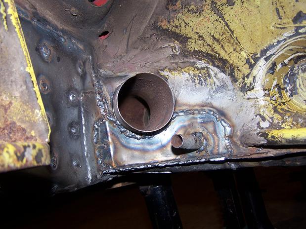
Posted by: Spoke Feb 10 2010, 09:27 PM
Triangle pieces by Spoke out of 16ga. Cost per piece: about $1 plus 1 beer.
Attached image(s)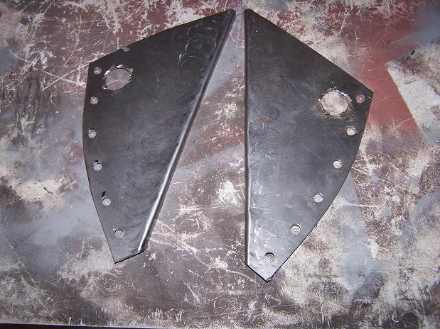
Posted by: rick 918-S Feb 10 2010, 11:05 PM


Posted by: Spoke May 3 2010, 06:12 PM
Yet another reason why I'm not working on my 914...Biz trip to Paris...Dammit
Attached image(s)
Posted by: Spoke May 10 2010, 09:31 PM
Finally done with my Audi heater fan, other Audi timing belt, Audi rear wheel bearing, 911 rear wheel bearing, 3 trips to Europe, 1 to Detroit, 1 to San Francisco, and I just finished cutting the grass.
Now some 914 work. Got the triangle plates welded in.
Had a minor safety scare. While under the car butt welding the triangles, I hit a gap and had a big splatter. I felt it come down on my head and my baseball cap protected my head but a piece found its way into my ear and I could hear my ear hair sizzling. I threw helmet and cap off and shook my head to get the weld out. Didn't have much pain but it did scare the crap out of me. I used a pair a ear plugs after that.
Left Triangle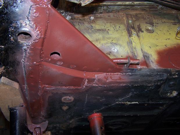
Closed up the tail shift mounting hole with a bolt. Threaded it in, cut it off, and welded shut.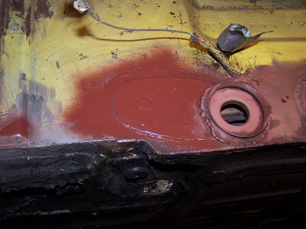
Right plate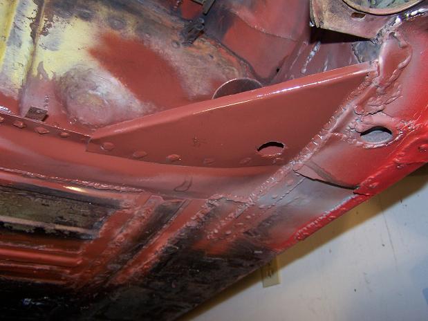
Posted by: Spoke May 11 2010, 09:41 PM
Found some rust on the engine mount. What a shock.
Attached image(s)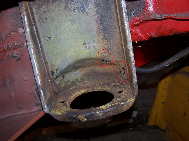
Posted by: Spoke May 11 2010, 09:57 PM
Finished up the last of the welding in the engine bay. Just did a few tabs for the fuel lines, brake lines, and ebrake cables.
Attached image(s)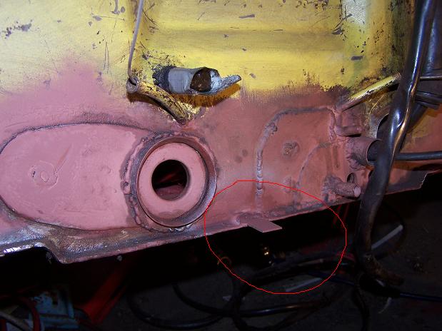
Posted by: Spoke May 14 2010, 10:45 PM
While poking the inside of the engine mount, I poked through the outside of the mount. A better man would replace the mount. That dude don't live here. Cut out the old stuff and weld in new. The top hole is just between sheets of metal. I closed that one up too.
Attached image(s)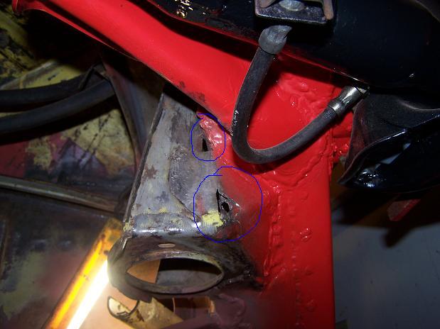
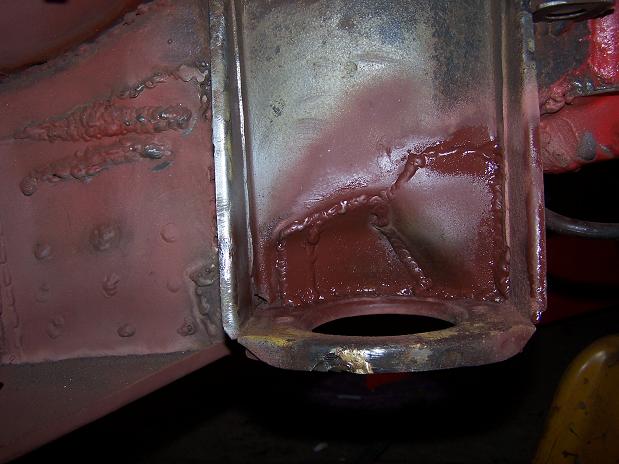
Posted by: Spoke May 14 2010, 11:32 PM
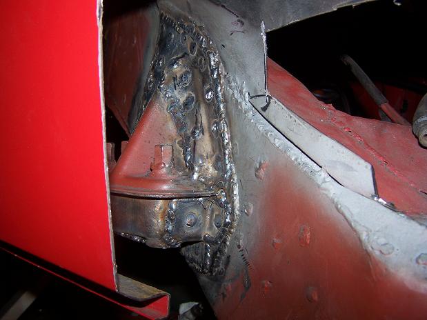
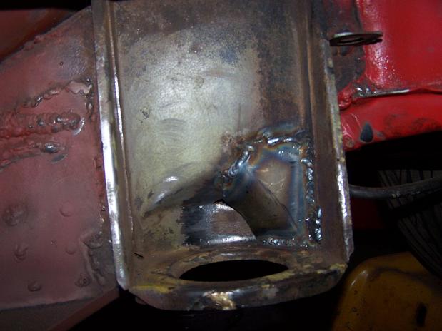
The long is gone behind the engine mount. Look Ma, no hole now.
Attached image(s)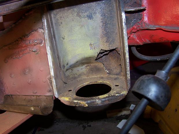
Posted by: wayne1234 May 15 2010, 09:28 PM
I was in the same situations a few months ago on mine, kinda got a flash back .. for a while it seemed like the welding wouldn't ever end, but it did, now all I need to do is finish the interior... I had a sizzle in my ear also, but didnt learn much from it, and it happened at least 2 more times  Thats Why I say I have literally put in blood sweat and tears...
Posted by: Spoke May 17 2010, 09:41 PM
The bolts that secure the swing arm adjustment plates snapped off several years ago so I drilled out the bolts and added a nut on top to secure the swing arm.
Solution is to weld bolts to the existing support. To get more grip length I welded 2 bolts together.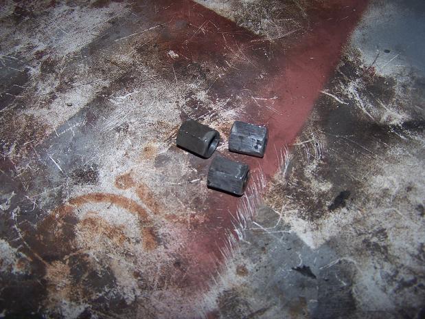
Nuts welded on.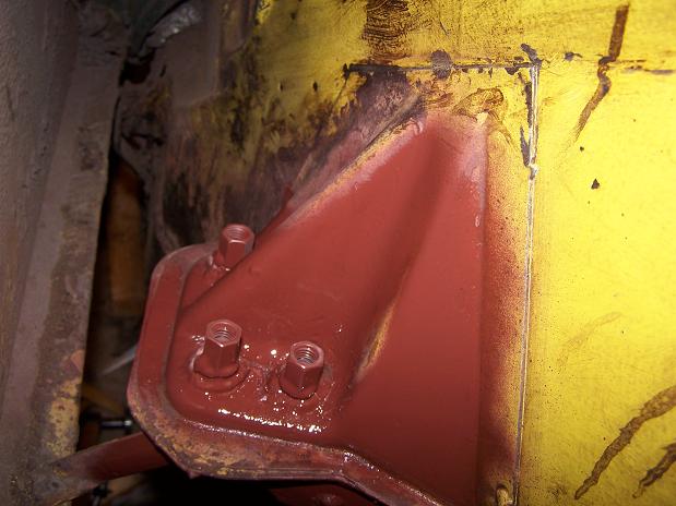
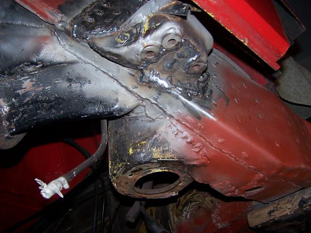
Posted by: Spoke May 17 2010, 09:54 PM
Finally finished with the engine mount.
This is the last of the welding to be done in the engine compartment. Next comes cleaning off the rest of the undercoating and tar, then wire wheel more of the rusty areas, sand, then paint.
Attached image(s)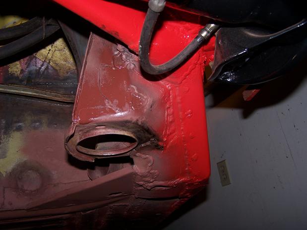
Posted by: Spoke May 23 2010, 04:12 PM
I welded a similar 16ga plate on the passenger side so decided to weld one on the driver side. Also seam welded the upper and lower firewall. Needed to weld this before prepping the engine bay for paint.
Attached image(s)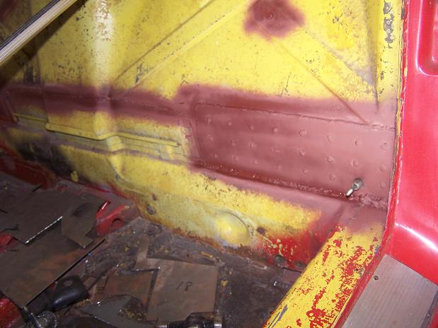
Posted by: Spoke Jun 4 2010, 09:01 PM
Finally finished all the welding in the engine compartment.
Seam sealed all the new welding and also some old stuff that I didn't seam seal before when I repaired the trunk floor.
Painted all the surfaces inside the engine compartment.
Attached image(s)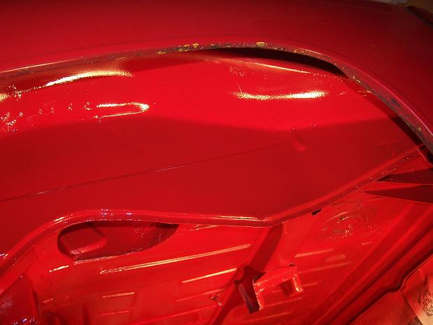
Posted by: Spoke Jun 4 2010, 09:32 PM
More Paint...
Attached image(s)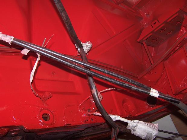
Posted by: Spoke Jun 4 2010, 09:34 PM
More paint...
Attached image(s)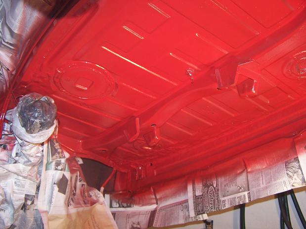
Posted by: Spoke Jun 6 2010, 06:21 AM
Cleaned and painted the suspension pieces.
Next steps to clean up fuel tank area which will include some rust repair and painting, plumb and wire fuel pump up front, then run fuel lines.
Attached image(s)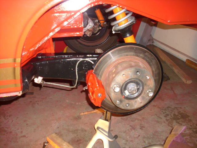
Posted by: Spoke Jun 7 2010, 07:30 PM
Finally on 4 wheels again. The jackstands are idle for the moment...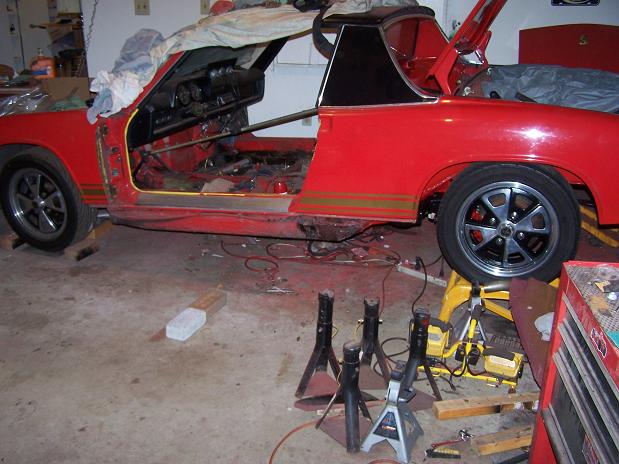
Next jobs are rust repairs in and around the gas tank. There's a rust through hole in the fender that I'm sure will grow once I start digging into it. I will also weld in an angle iron brace to support the Camp914 hood shocks.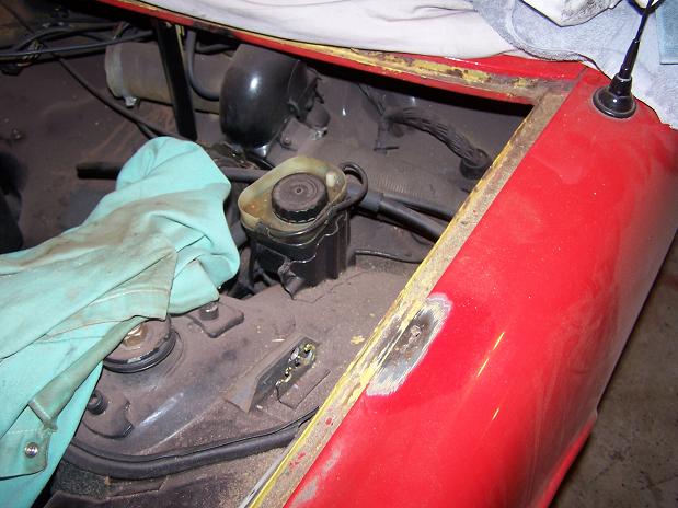
The passenger side corner was totally gone so I'll fabricate some new pieces and weld in.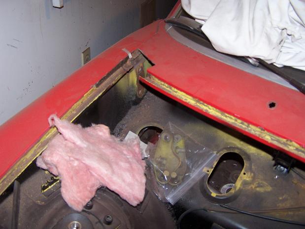
Posted by: Spoke Jun 18 2010, 06:55 AM
Welded up the hole in the fender and the weatherstrip channel.
Also welded on a piece of angle iron to strengthen the hood shock (spring) mount. When I put on the hood shock a while back, the original spring mount just bent under the stress of the shock. So I got a piece of angle iron to back it up. I didn't weld it back then as it wasn't necessary.
Welded the gap between the fender and cowl too. This got real weird near the end when I got a lot of spitting and popping. I thought at first that my gas had run out, turned off, or got clogged, but I found that there was lead on top of the fender and that's what was popping and spitting.
Attached image(s)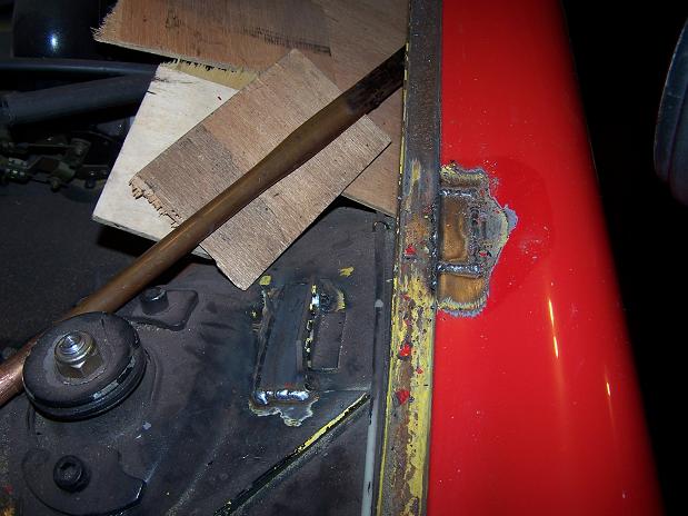
Posted by: Spoke Jun 21 2010, 09:13 PM
Welded and ground down the 2 patches on the driver side.
Attached image(s)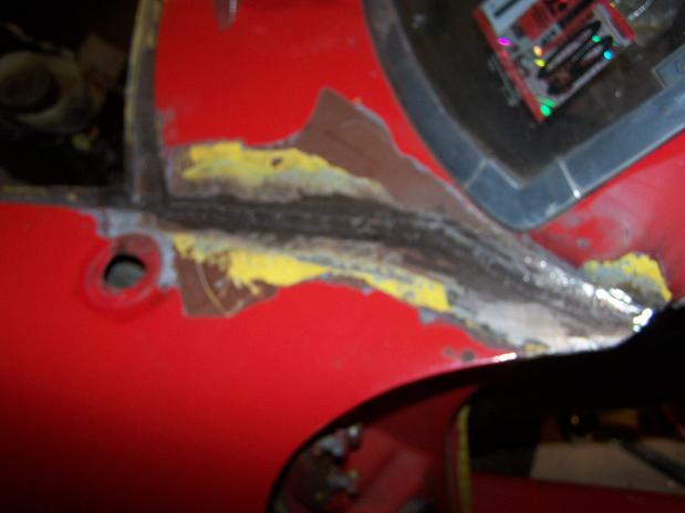
Posted by: Spoke Jun 21 2010, 09:16 PM
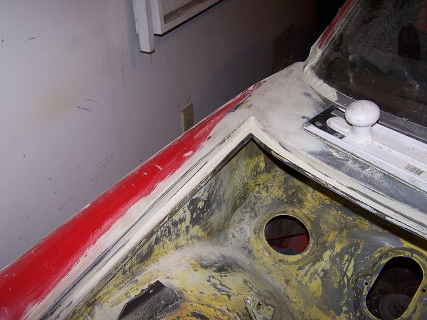
Next project is the passenger side corner drip edge. This side was rusted more than the driver side and I had to remove a large chunk of the cowl.
Attached image(s)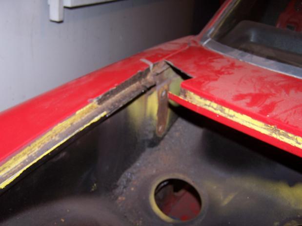
Posted by: Spoke Jun 21 2010, 09:30 PM
So after about 3 months of contemplation of how to make this one piece with its bends and arches and one failed mock up, I decided to make it out of 4 pieces of steel and weld it together.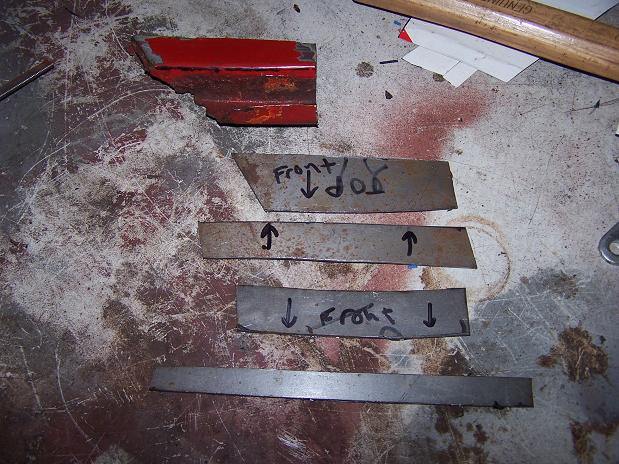
The fabrication time was probably about 2 hours and turned out great. I'll weld the inside lip after placing the main patch.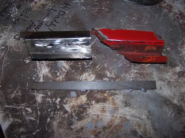
Posted by: Spoke Jun 28 2010, 08:15 PM
Welded the drip edge in. Not my best work but it will do.
Attached image(s)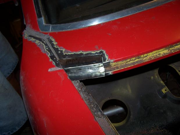
Posted by: Spoke Jun 28 2010, 10:08 PM
Welded the angle iron to stiffen the hood shock mount and welded the drip channel lip. Still need to clean up the welds.
Attached image(s)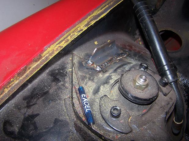
Posted by: Spoke Jul 1 2010, 04:33 AM
Cut out the trap door for the fuel pump. Since the inside of the trunk was painted black and my black magic marker doesn't show up, I cut out the correct size of the hole from card stock, taped in place, then sprayed silver paint to outline.
Once cut out, I used the piece from the hole and backed it up with a larger piece of 16ga steel. I'll drill 4 holes for bolts in the corners and weld nuts on the inside to secure the door.
I thought seam welding the cutout to the new steel would be easy but I forgot to clean off the backside of the cutout and the paint that burned off during welding really made the job messy. What an ass.
Attached image(s)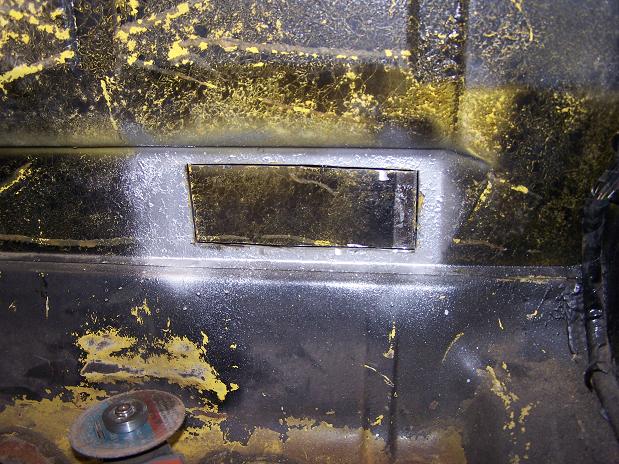
Posted by: FourBlades Jul 1 2010, 06:24 AM
Nice repair work man.
That cowl area is a real pain to fix.
John
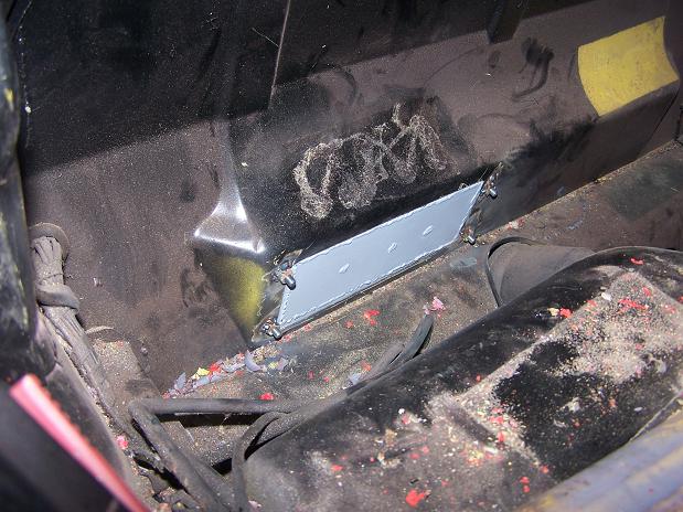
Posted by: Spoke Jul 2 2010, 05:42 AM
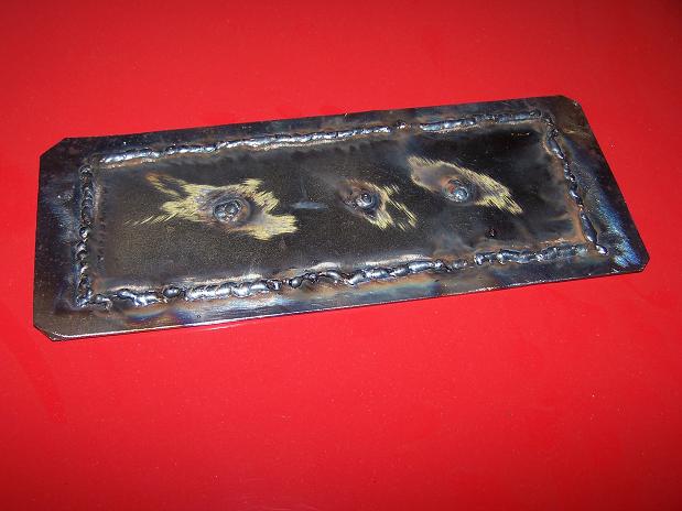
Fuel pump door is in. Drilled 4 holes for bolts and welded the nuts on the inside of fuel tank area.
Now I need to source a mount for the fuel pump. Anyone have a rubber mount for the fuel pump that they want to sell?
Next job is to run the wires for the fuel pump from the engine compartment to the front.
Attached image(s)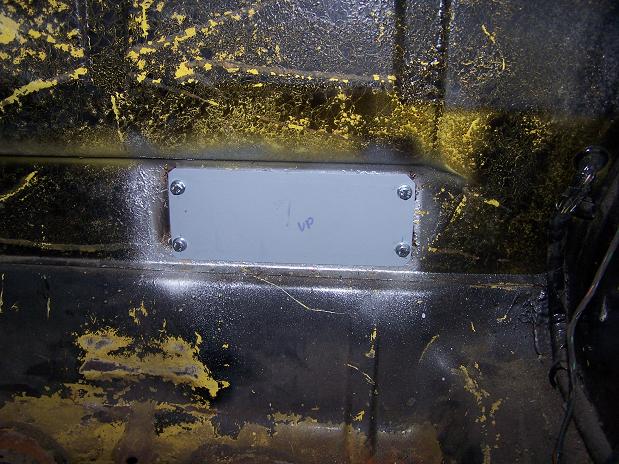
Posted by: Spoke Jul 4 2010, 12:46 PM
Ran new hard brake lines in the engine compartment. Replaced the prop valve as I plan to 5-lug at some time with 911 front end.
The PO's mechanic had cobbled together the hard lines to each swing arm from smaller pieces of tubing. The passenger hard line was actually 3 small pieces with connectors and the driver side had 2 pieces.
Once the brake lines were connected, I was finally able to remove the stick holding the brake pedal in. The stick had been there for over a year...
I did pull a damn PO move though with the T. I couldn't find a metric T locally so I used an SAE T with SAE threads. So the end of each line to the T has SAE connectors and the ends to the tunnel and each swing arm has metric. Damn PO!
Attached image(s)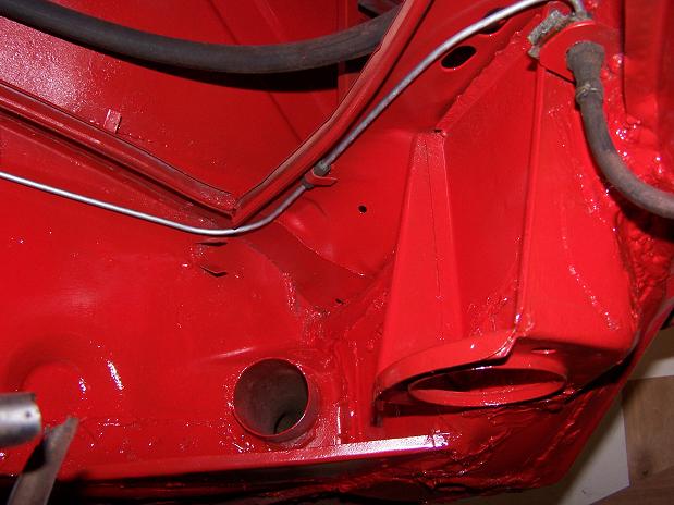
Posted by: Spoke Jul 4 2010, 02:18 PM
Hole, what hole? Since I will plumb the gas tank so that it can be lifted out without disconnecting fuel lines, the access hole is not needed.
Attached image(s)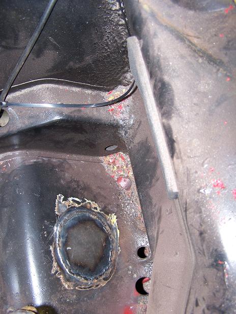
Posted by: Spoke Jul 8 2010, 11:38 PM
Done welding and paint stripping in the tank compartment. I didn't remove all the original yellow paint in the compartment but at least the nasty black paint is gone.
I'll continue sanding in the compartment and start bodywork to smooth over the welds and clean up the rain channels.
It seems that inside the tank compartment there is no primer underneath the original yellow paint.
Attached image(s)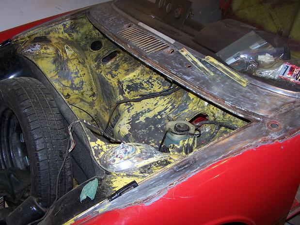
Posted by: Spoke Jul 10 2010, 01:01 PM
I thought I was done with the welding in the tank compartment until I started wirewheeling the channel and had several large holes in the channel floor.
The piece of wood sets the width of the channel since the outer lip is not supported by anything now.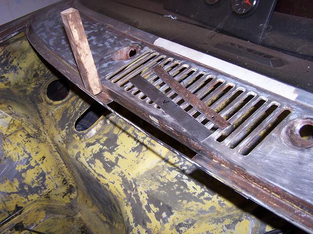
New floor welded in. 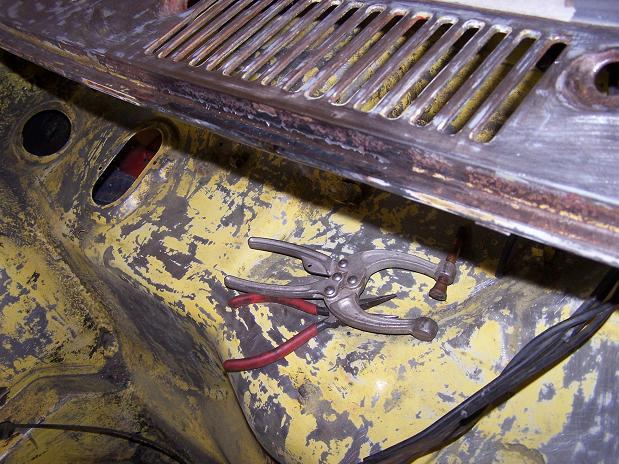
I decided to get rid of the antenna mast so antenna hole is welded closed.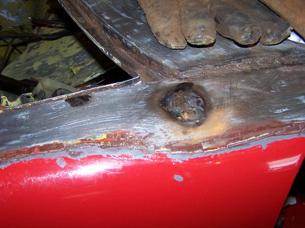
Posted by: Spoke Jul 11 2010, 08:27 PM
Closed up the hole for the antenna into the tank compartment.
Attached image(s)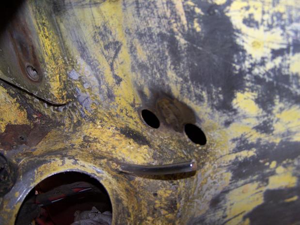
Posted by: Spoke Jul 11 2010, 10:58 PM
The e-brake cables were broken when I purchased the car. The adjustment ferrule for both cables had been snapped and the cables dangled a bit as they exited the firewall. Today's job is to weld the adjustment screw back together.
Since the adjustment point was right where the break was on each cable, I have to cut back the portion attached to the cable like the cable on the top in the photo.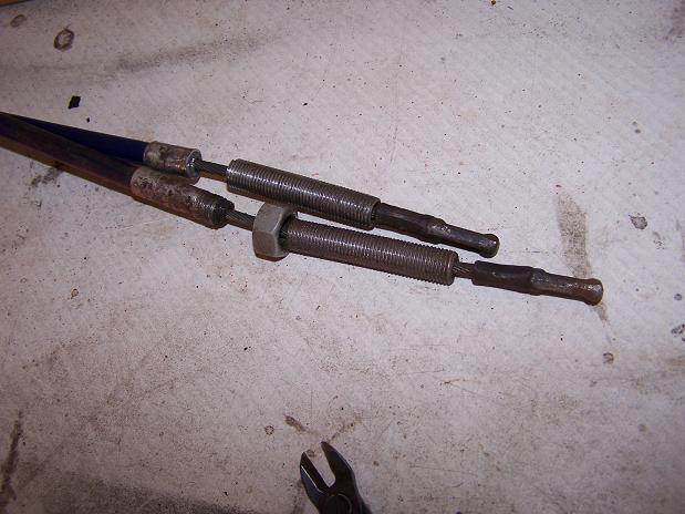
To get the two pieces straight, I used an angle iron and some clamps to start the welding.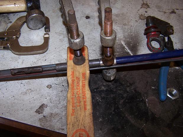
I welded each piece with just a little dot of weld then let the screw cool so I didn't overheat the steel and plastic sheath of the cable. Both cables came out good and are ready for reassembly.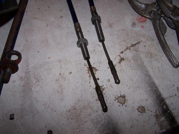
Posted by: Spoke Aug 1 2010, 08:04 PM
All the metal work is done around the gas tank. Now smoothing everything out with bondo. It doesn't bother me to use body filler as long as it's to smooth out solid metal.
Got it where I want now. Need to do a skim coat and some contrast primering to get it just right.
Attached image(s)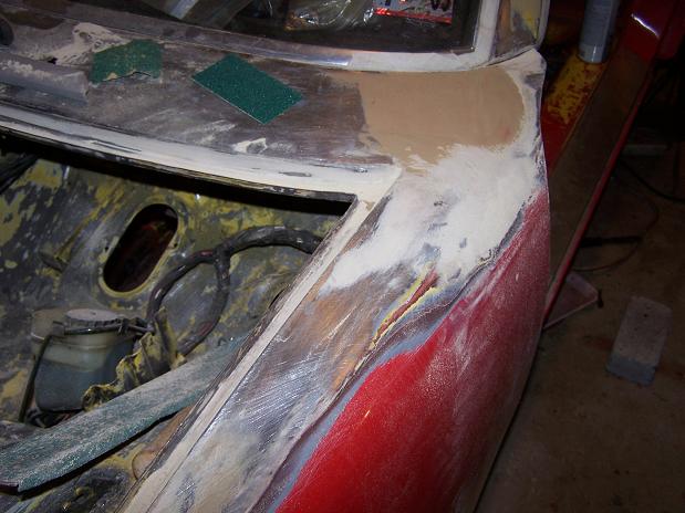
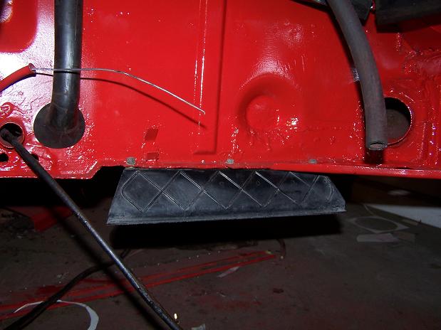
Posted by: Spoke Aug 1 2010, 08:07 PM
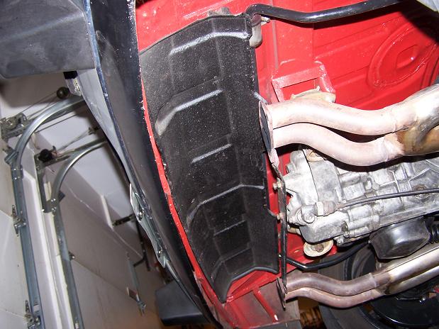
Mounted air deflectors. Now the engine cooling system will breath very smoothly.
Attached image(s)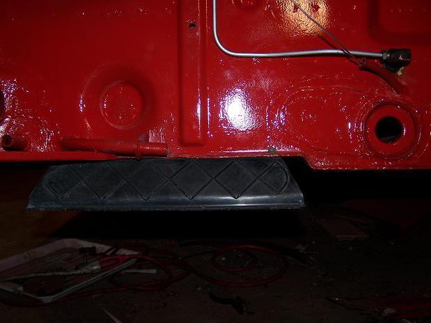
Posted by: Spoke Aug 1 2010, 08:14 PM
I decided instead of welding the pieces that I cut out of the tunnel to re-weld the clutch tube that I would make them removable.
I took the pieces cut out of the tunnel and traced and cut out larger pieces of 18ga steel. Then I cut off 1/4 inch off of each and welded them to the larger pieces.
Since I'm using the original cut-out pieces, they fit like a glove...
Attached image(s)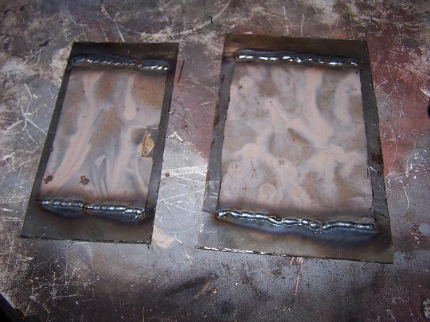
Posted by: Spoke Aug 9 2010, 09:37 PM
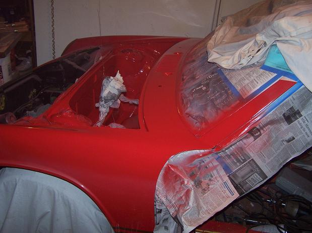
Finally getting ready to paint the tank area and cowl. Got everything masked off and now will start with primer.
Attached image(s)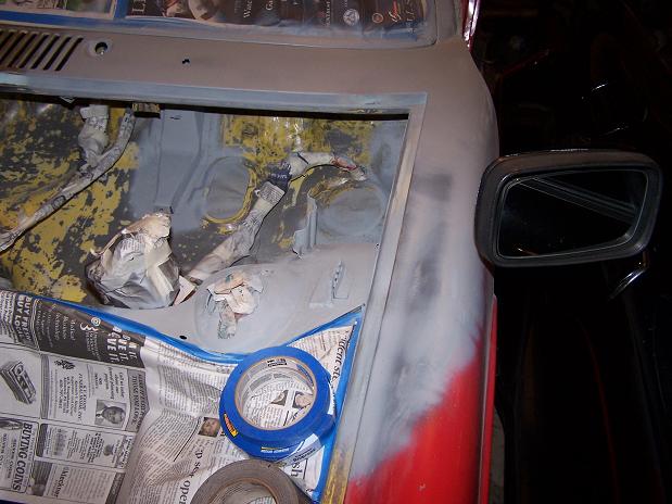
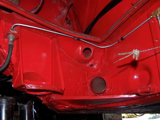
Posted by: Spoke Aug 14 2010, 11:46 AM
Finally, it's gas tank compartment and cowl paint day. Primer is on and all loose ends (minor deep scratches) are taken care of.
The master cylinder is wired to the ceiling to keep it out of the way as much as possible. The wire bundle is also suspended by the same wire. The wire is 24 ga welding wire that is wasted when you run out of weld wire in the MIG welder.
Attached image(s)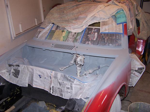
Posted by: Spoke Aug 15 2010, 03:12 AM
Paint is on.
Next tasks after paint cleanup is to run the steel fuel lines, reassemble all the components inside the fuel tank compartment: Windshield wipers, air handling flappers and cowl air fan.
Install and wire the fuel pump, replace the tank and prepare to fire the engine using the tank, pump, and installed fuel lines.
I'll run long fuel hoses to the engine so I can run the engine and test all the electrics before installing the engine.
Attached image(s)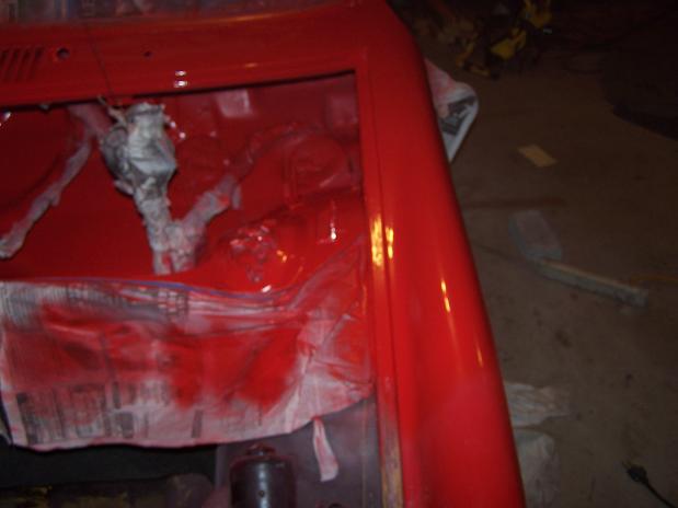
Posted by: Spoke Aug 15 2010, 10:54 AM
While I'm in there: I'll paint the rear swaybar...
Attached image(s)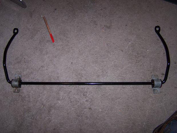
Posted by: Spoke Aug 16 2010, 08:31 PM
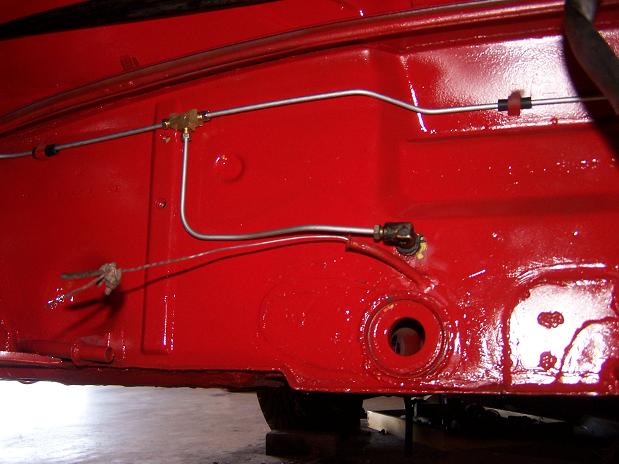
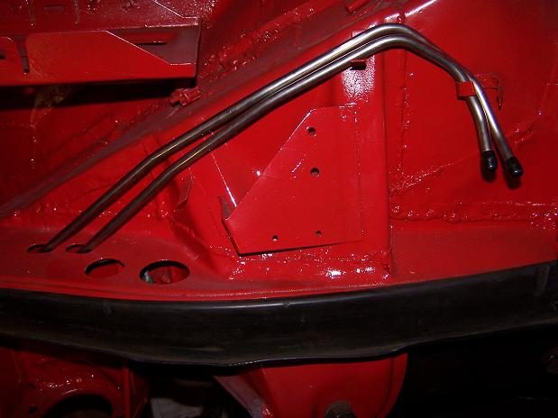
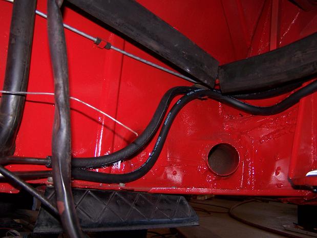
Tunnel SS fuel lines in. Engine compartment SS fuel lines just sitting in place.
Attached image(s)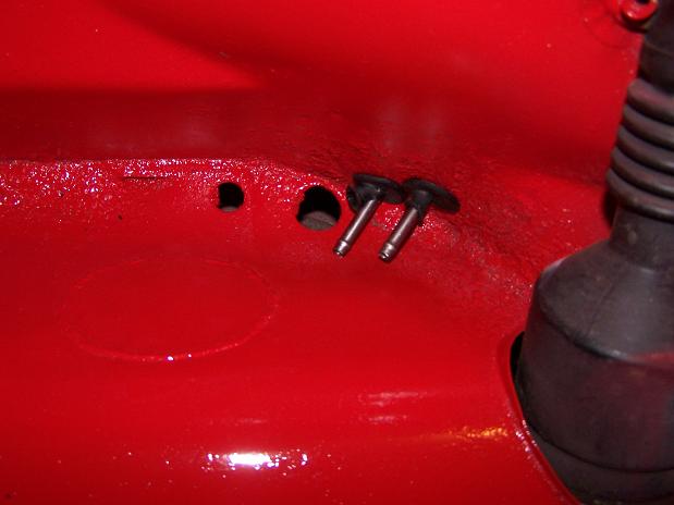
Posted by: Root_Werks Aug 17 2010, 01:16 PM
This looks like another 914 saved from the rust monster!
Nice work, things are looking really solid again.
Posted by: Spoke Aug 19 2010, 10:59 PM
Fixing a hole in the vent.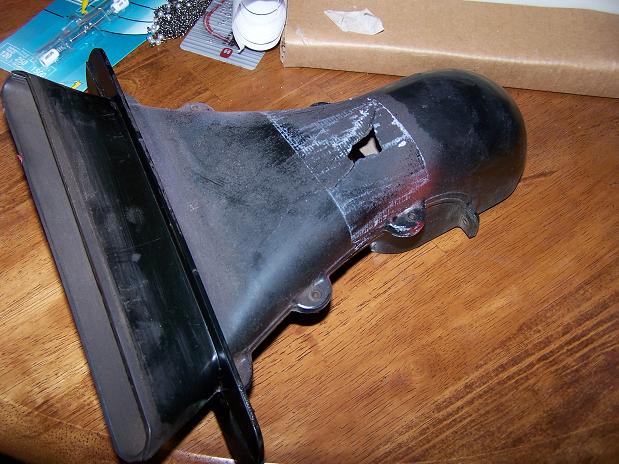
A little 22ga patch, a few rivets, and some silicon caulk and paint.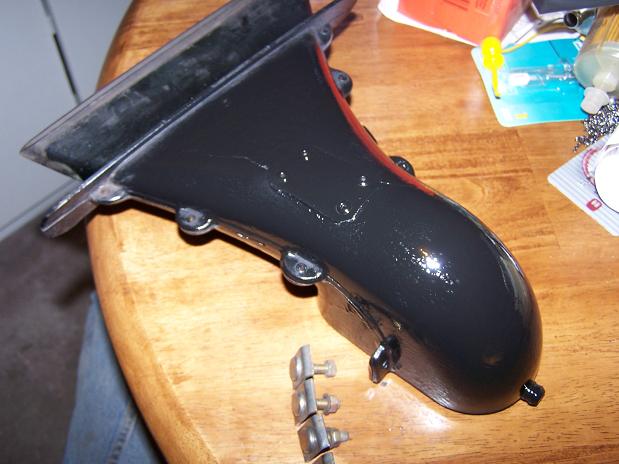
Cleaned up the securing bolts for the front flappers.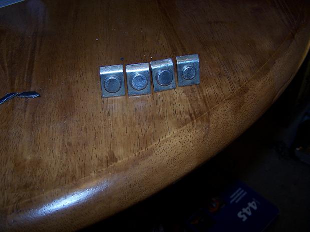
Posted by: Spoke Aug 20 2010, 04:38 AM
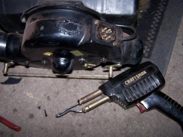
Fixing another hole this time in the fresh air fan where apparently in the previous life of this 914, the windshield wipers were run for a long time and the motor heated up and melted the outside of the fresh air fan.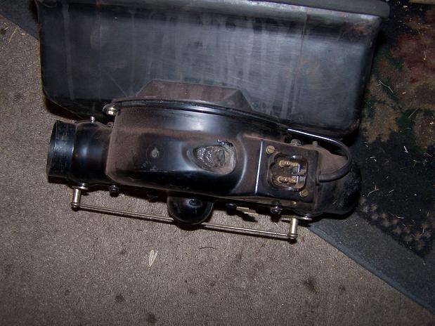
I didn't want to put a patch like on the flapper with rivets in case the rivets would interfere with the fan, so I got a piece of plastic and "welded" it in place with my 50 year old Craftsman solder gun.
Posted by: Spoke Aug 20 2010, 07:15 AM
All of the air handling equipment is back in along with the windshield wiper assembly and windshield washer hoses.
I connected the battery to test the windshield wipers and fresh air fan. Good thing I did because I had connected the wipers wrong as I was viewing my wiring template 90 degrees off and all 4 wires (not ground) were one spade off.
I'm almost back where I started in the front when I wanted to "pull the tank to put in SS fuel lines and locate the fuel pump up front" before the "while I'm in there" items got in the way:
1 Fix rust on both corners of the drip sill
2 Weld in the angle iron supports for the hood shocks
3 Weld in a bolt towards the interior for radio ground (was just a drilled hole + self-tapping screw).
4 Strip all the paint from the cowl and adjacent fender area
5 Weld-up fender-to-cowl gap
6 Remove all air handling equipment, windshield washer & wiper assembly
7 Remove hood cable release
8 Strip paint from entire tank compartment
9 Paint entire tank compartment, cowl, and adjacent fender area
Things left to do up front:
1 Secure brake reservoir
2 re-install cowl braces
3 finish wiring for front fuel pump. Wires coiled right behind pedal assembly
4 mount fuel filter
5 plumb fuel lines
6 re-install tank
7 reinstall windshield washer reservoir
Attached image(s)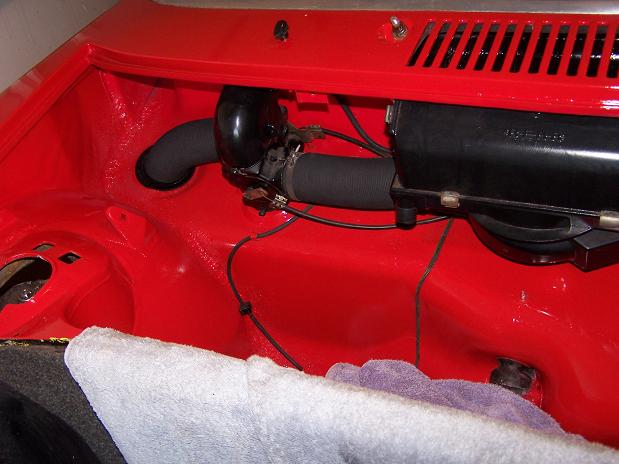
Posted by: Spoke Aug 21 2010, 04:35 PM
Turned the car around to get it in position for engine install.
Attached image(s)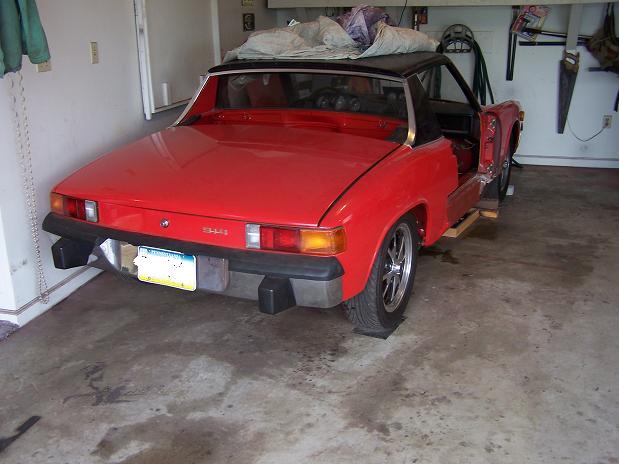
Posted by: Spoke Aug 21 2010, 04:43 PM
Got the firewall shift bushing in. Boiled the bushing in water in the microwave to warm it up. A couple of slugs with the hammer and it popped in.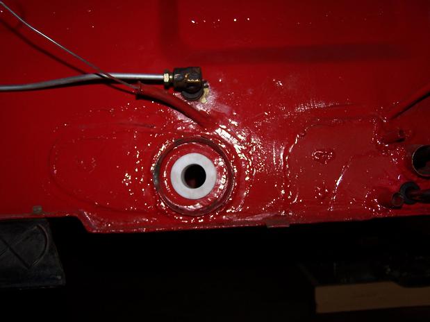
Installed new bushings into the coupler. 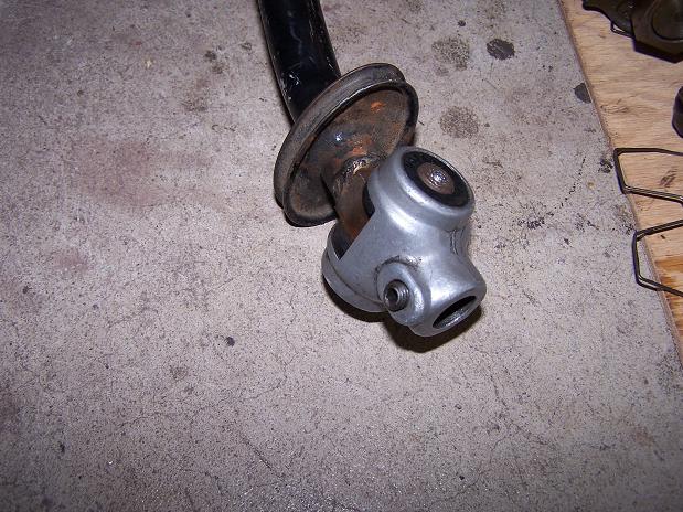
Posted by: Spoke Aug 21 2010, 04:48 PM
Before the engine goes in, there are a few things to tidy up:
1 Leaky pushrod tubes. Doing that now.
2 Install sideshift engine bar
3 Install alternator
4 Add 150 ohm resistor to HCT sender. It's resistance is a bit low.
5 Run engine before installing to check out all systems
For now, changing leaky pushrod tubes. These ones came out of the driver side. Notice the chunks taken out of outside o-rings. No surprise of why these were leaking. And to think this engine was freshly rebuilt by GEX...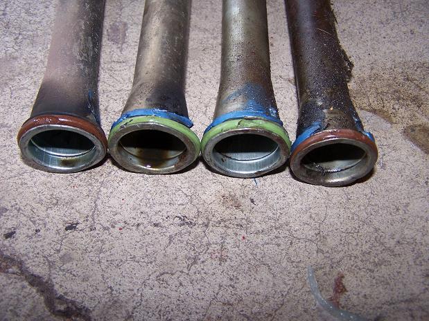
The inside o-rings look good but will be changed anyway. Why are there 2 colors for the o-rings? Different manufacturers?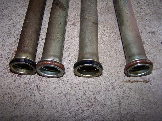
Posted by: Spoke Aug 22 2010, 01:13 AM
Not much left of this o-ring. There was plenty of gasket sealer on this tube but it still leaked. How shocking. 
This nut looks like it had some sort of welding done to it or it is fractured in 2 places. No wonder I couldn't snug this one down...
Attached thumbnail(s)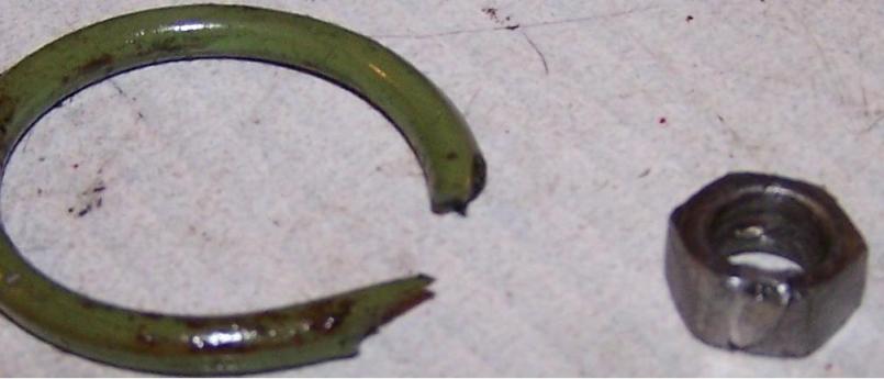
Posted by: Spoke Aug 22 2010, 06:51 PM
Got the pushrod tube o-rings put in and adjusted valves.
Finished plumbing the wires for the front mounted fuel pump.
Went through the front firewall just above the boxed support.
Attached image(s)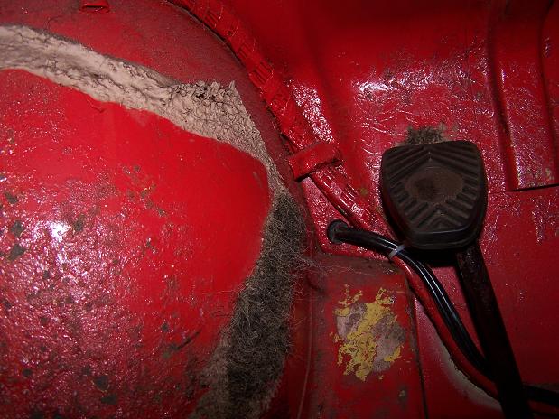
Posted by: Spoke Aug 22 2010, 06:52 PM
Tested the fuel pump relay by grounding pin III of the FI connector.
Got 12V at the front of the car for the fuel pump.
This also means that the 12V for the FI brain is ok since it also drives the relay for the fuel pump.
Posted by: Spoke Aug 22 2010, 07:02 PM
Before installing the engine, I would like to clean out the oil in the heat exchangers that has dripped from the pushrod tubes. There's a gooey oil mess on the inside bottom of the exchangers.
Any ideas of how to clean this out? I'm thinking some type of degreaser and then I'll have to somehow flush the inside of the exchanger with water or other solution.
Attached image(s)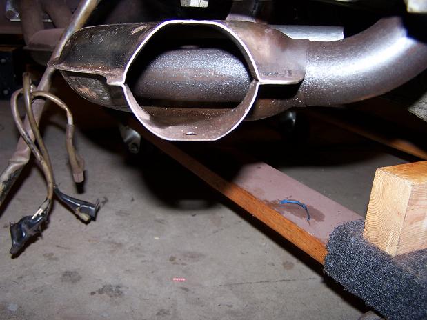
Posted by: Gigamight Aug 22 2010, 09:10 PM
I have no answer for you, but I am anxiously awaiting an answer to this question.
If anybody has a trick, please share it.
Posted by: messix Aug 22 2010, 09:38 PM
dish soap and a bottle brush
Posted by: Spoke Aug 23 2010, 07:06 AM
Getting the alternator back together. I needed to make the back panel gasket. To do this I used PowerPoint to make 2 concentric circles with 3 lines coming out at 120 degree increments for the bolt holes.
Attached image(s)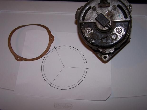
Posted by: jaxdream Aug 23 2010, 07:07 AM
Also might could try using some spray on / in oven cleaner. You could use the popular easy off , or get some other brand ( cheaper ) spray in both ends , tilt back and forth , let it run down inside , take to car wash to pressure spray out . I have used this method on the outside and works great , next is the inside . Good luck ...
Jack / Jaxdream
Posted by: Spoke Aug 25 2010, 08:29 PM
Fabbed the fuel pump mounting tonight. I started with a rubber coupler from Home Depot with 2 hose clamps and cut the coupler so I had 2 pieces. The hose clamps will hold the pump in place and the coupler will provide some chassis buffering from the pump vibrations.
First order of business was to make 4 slots for the 2 hose clamps. My trusty Dremel tool with doubled cut-off wheels made just the right size slots for the clamps.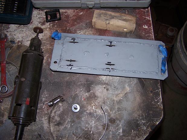
Looks like everything fits together real good. The pump was placed to one side of the door so that I can pull the pump out on one side followed by the other. If I centered the pump, I might have trouble bending the hose to clear the bulkhead.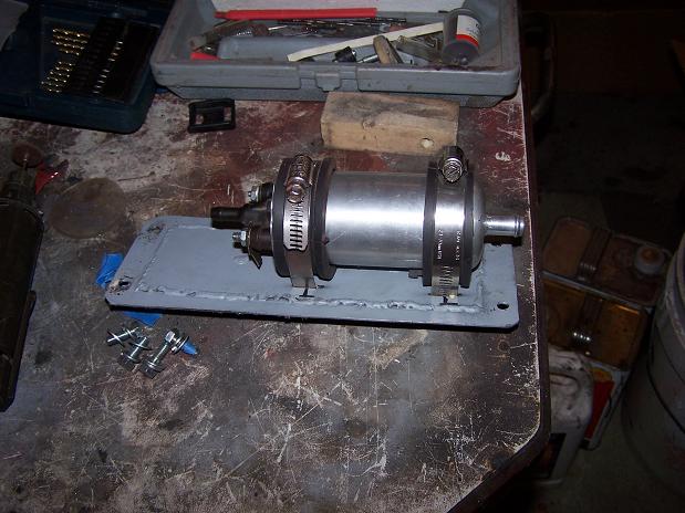
Placement in the tank compartment looks good. I couldn't use the standard pump mount since the pump would hit the brake lines.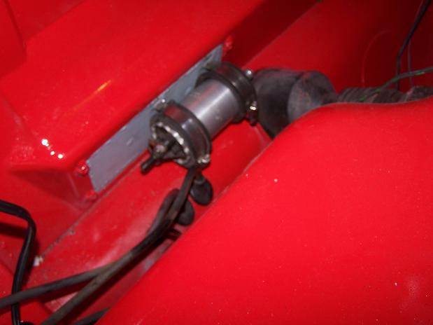
Posted by: Spoke Aug 28 2010, 11:19 AM
Pulled the tunnel fuel lines and bent them a little more to get some clearance for the hoses. 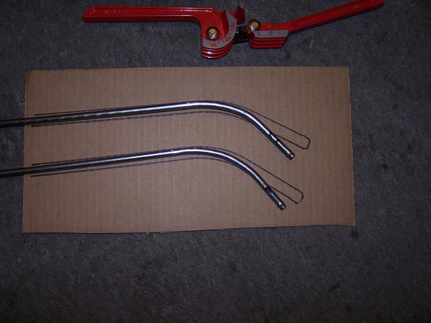
Just enough clearance to get the hoses on.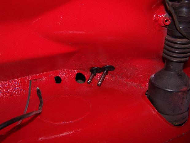
All the under-tank fuel hoses, fuel pump and filter are installed. I left enough hose to easily pull out the fuel pump and filter as well as be able to lift the tank out without disconnecting any lines.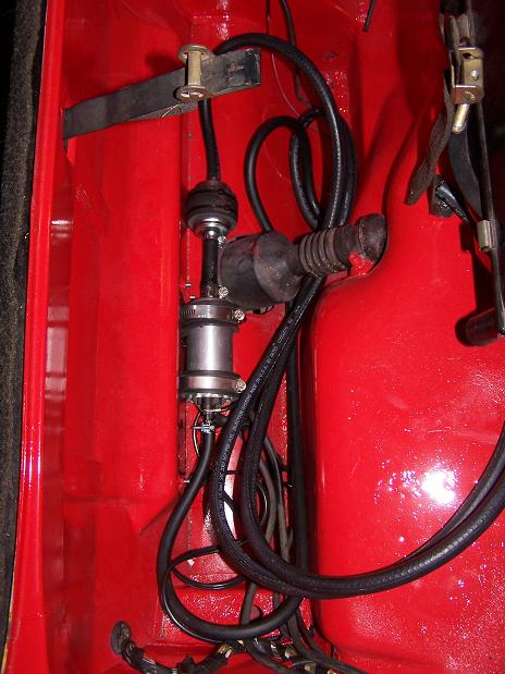
Posted by: Spoke Aug 28 2010, 11:40 AM
Fired up the engine before starting the install. I used the fuel system from the car to fire the engine. Also connected the battery to the starter using the car's starter cable.
The ground for the engine uses the cable that came with the engine for the starter cable. I connected the ground to the normal pigtail ground connection that goes to the tranny. I had to make very good connections as I am testing the alternator as well.
Engine runs good, everything checks out.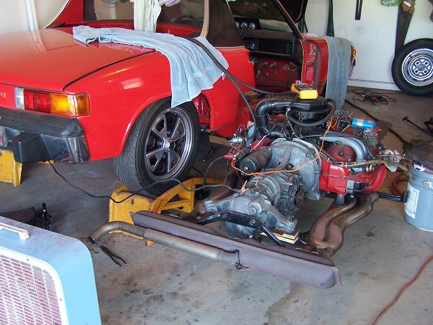
Fuel tank hoses are long enough to pull the tank without disconnecting the hoses. The fuel pump is running by shorting pin III to ground on the relay board. No leaks detected. Yea!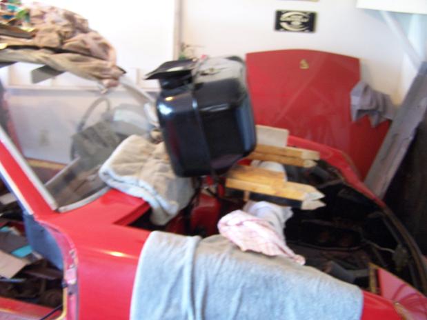
I tested the alternator by shorting D+ and B together then pulling them up to 12V through a resistor box. Got over 16V with the engine running so the alternator looks good.
Time to install the engine. 
Posted by: Spoke Aug 28 2010, 08:50 PM
Engine is installed!!!
It was a one man job. I used a piece of 2x8 by 16 inches under the engine and tranny and kept adjusting the position of the jack until the engine was perfectly balanced.
Only had 2 snufus:
1) The fuel injectors+hoses stuck out just a little too far and had to be removed before installation.
2) I jacked the car up so high that I couldn't get the engine totally in with the jack. I got the engine bar secured but the tranny was about 8 inches low with full jack extension. So I temporarily supported the tranny and got several more 2x8s and put them on top of the jack to get the necessary height.
Attached image(s)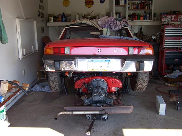
Posted by: Spoke Aug 28 2010, 11:28 PM
My 71 is now a sideshift car.
Attached image(s)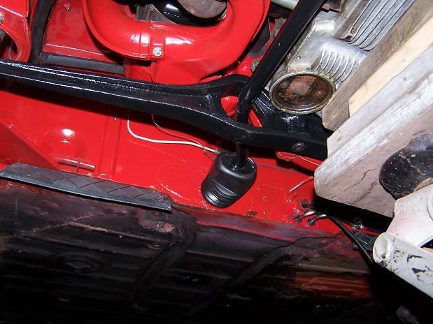
Posted by: Spoke Aug 29 2010, 04:03 PM
First Drive!! It runs ok, doesn't idle real nice but gets along when on the gas.
The car is registered and insured so it is technically drivable. Yeah it has a hole in the fender. I'll tack on the piece cut out just to get it inspected.
Attached image(s)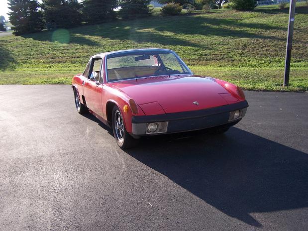
Posted by: rick 918-S Aug 29 2010, 08:00 PM
Nice progress. I remember when that car was whacked! So, are you thinkin Tail of the Dragon? 

Posted by: FourBlades Aug 29 2010, 09:02 PM
Excellent!!!
It is such a great feeling getting one running again.
John
Posted by: Spoke Sep 11 2010, 12:55 PM
PA State inspected! 
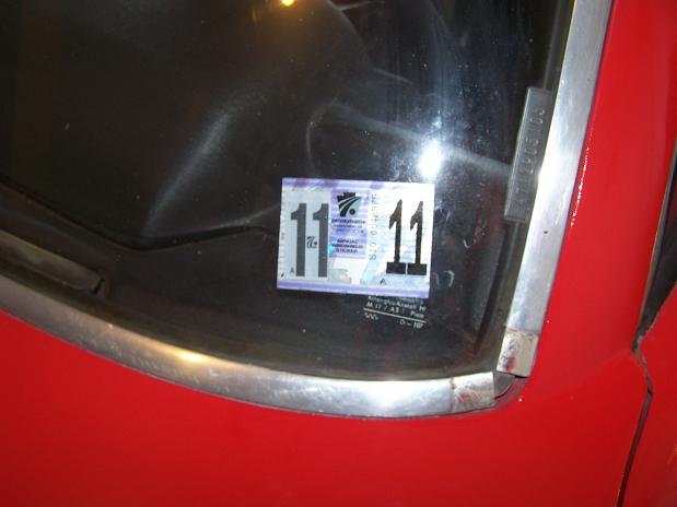
I had to put the e-brake cables in as well as the e-brake handle for the inspection.
The last order of business for the inspection was to tie down the battery. My mount is a FLAPS special that originally held the battery secure in the trunk. I used the mount when I relocated the battery to the engine compartment. I made the hold-down straps out of 18 ga steel and drilled a hole for the bolt to secure everything. The battery is rock solid.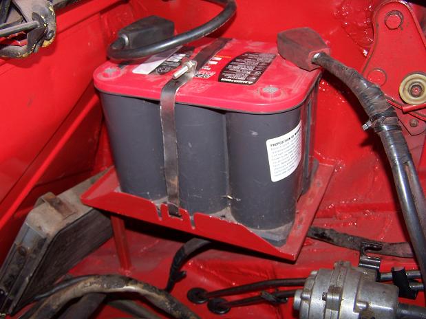
Posted by: Spoke Oct 17 2010, 11:58 AM
Update: The engine is running real nice now. I had to enrichen the engine a bit by adding resistance to the CHT sensor. I went from 150 ohms extra to about 350 ohms. I know I should make adjustments to the MPS to enrichen the mixture but the CHT mod is easy.
Haven't had many issues since getting it on the road. Put a bunch of miles on it driving around town. Starts right up, idles good. It does seem to suck oil though. It doesn't leak oil at all but I've had to put about 3/4 qt in once a week. I wonder if not having an after-run valve could cause high vacuum in the cylinders and sucking oil into the chambers.
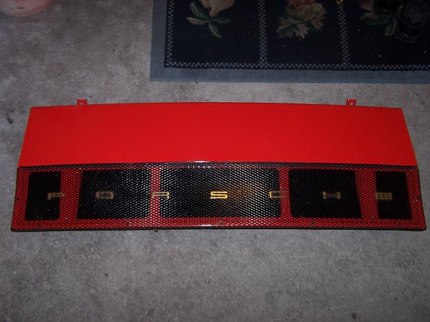
Yesterday after driving it, I noticed the "S" in PORSCHE had fallen off the engine lid and was just lying there.
Then the "While you're in there" syndrome took over and now I'm stripping and painting the entire engine lid. So a missing "S" has led to a full strip and paint of the engine lid.
Attached image(s)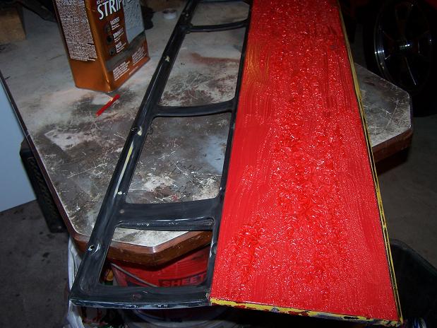
Posted by: Spoke Oct 19 2010, 08:32 PM
Strip paint in the morning, prime and paint all in one day.
Attached image(s)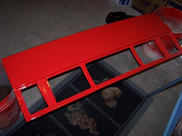
Posted by: Spoke Oct 21 2010, 09:03 PM
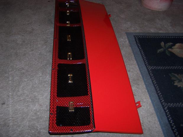
Got the engine lid back together. It's amazing how much work it took to put the "S" back on the lid.
But it sure does look pretty.
Attached image(s)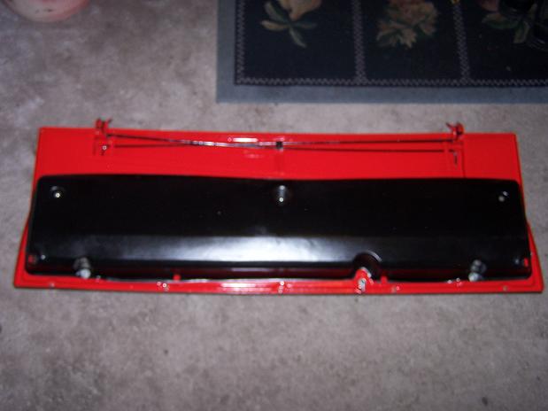
Posted by: Jon Fernandes Oct 21 2010, 09:07 PM
Looking good! 
Posted by: Spoke Nov 17 2010, 08:12 PM
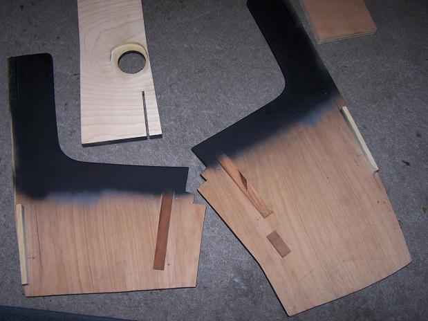
I made a center console (actually this is the 2nd one) from wood using the original as a starting template.
The sides are high enough that they wedge in between the floor and the dash and thus do not need any securing straps.
I made the opening for the shifter to use the original shifter boot so I don't need one of the vinyl console ones.
An original gauge faceplate sits right in the slot of the bottom panel and just rests between the 2 side panels.
Attached image(s)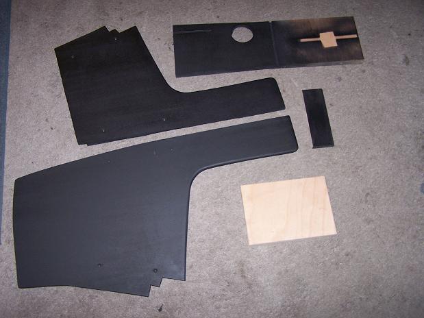
Posted by: Spoke Nov 17 2010, 08:47 PM
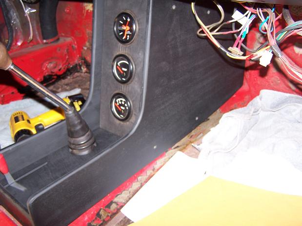
Install goes like clockwork. 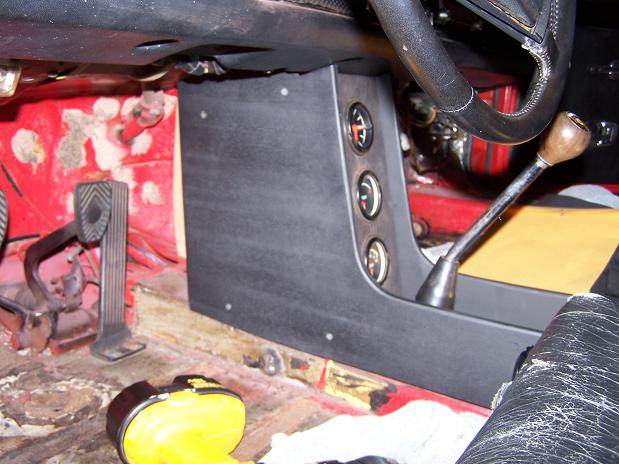
Speaking of clockwork, this is the 3rd clock I've installed in the console. The first 2 were the motor driven type that originally came in the 914. Both have had some gear degradation leading to clock failure.
This one is a later model VDO unit that I got off of evilbay. This one is a quartz driven clock with second hand. It was originally a 2inch clock that I modified an original 2-3/8 inch case to accept the clock mechanism. I used the original 2-3/8 face, protective clear face and bezel.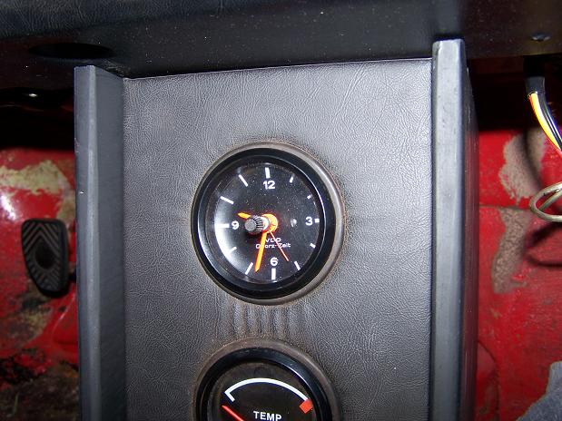
Posted by: Spoke Nov 24 2010, 04:38 PM
Got the oil temp sender installed. Had to make the gasket between the seal plate and protection plate. Yea, no leaks.
I ran the wire along the engine bar and up through the grommet for the alternator wires. I put the wire in heat shrink tubing to protect the wire under the car.
Attached image(s)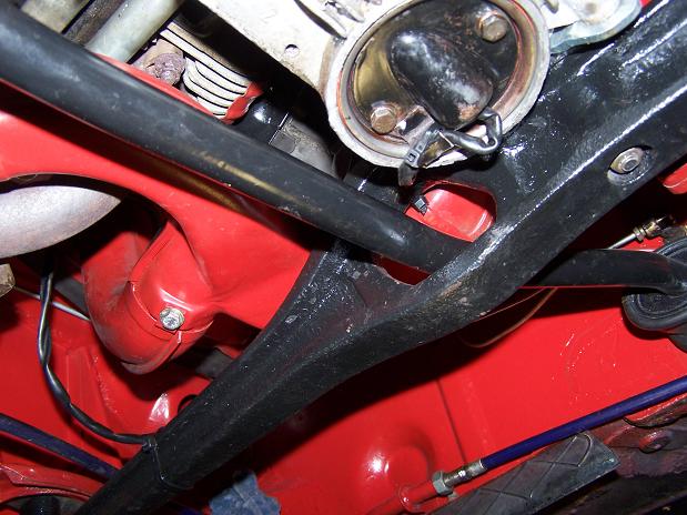
Posted by: Spoke Nov 24 2010, 10:15 PM
Remounted the muffler heat shield. I mounted it before with bolts instead of rewelding it back on.
This worked good when I decided to clean up and paint the bottom of the car. Only took about 5 minutes to reinstall.
Attached image(s)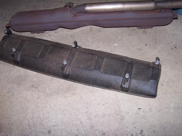
Posted by: arkitect Nov 25 2010, 10:57 PM
Jerry,
Great build thread, enjoyed the picts of all your welding repairs.
This is your 71, are you still planning on doing your 74?
Dave
Posted by: Spoke Nov 26 2010, 06:29 AM
Jerry,
Great build thread, enjoyed the picts of all your welding repairs.
This is your 71, are you still planning on doing your 74?
Dave
Dave,
I sold the 74 last year to buy my 911 turbo. Wife said 2 Porsches are ok but not 3.
The 74 is now for sale in Philadelphia. This is a great car if someone is looking for a nearly rust-free 914 in the northeast, this is it. Plus 2L and 911 front end and Eric Shea 5-lug rear.
http://www.thesamba.com/vw/classifieds/detail.php?id=866429
Posted by: Spoke Dec 5 2010, 11:11 PM
Just arrived this weekend.
They're not pretty but the price was right. 6x16 and 7x16 Fuchs for $400 shipped.
I need to clean these up but that's ok since I need to procure the necessary 5-lug suspension pieces before mounting. Will be looking for 911 struts with 3.5inch calipers.
I plan to polish the rims and petals and paint the background black.
Attached image(s)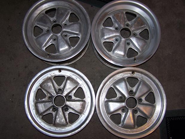
Posted by: Spoke Dec 8 2010, 06:57 AM
Removed the anodizing with EZ-Off.
Attached image(s)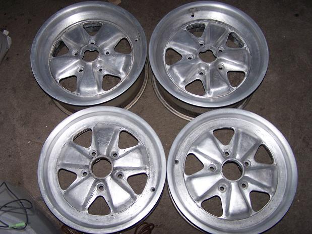
Posted by: Spoke Dec 8 2010, 04:57 PM
Oh, yeah, the wheel deal included center caps.
Attached image(s)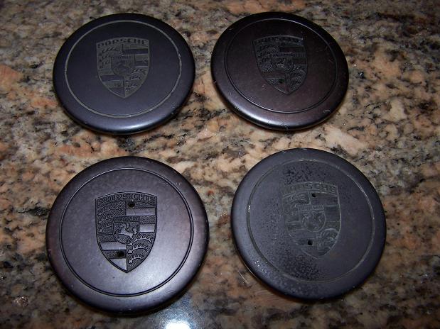
Posted by: rdauenhauer Dec 8 2010, 05:59 PM
Go Man Go!
Posted by: Spoke Dec 8 2010, 08:02 PM
After EZ Off...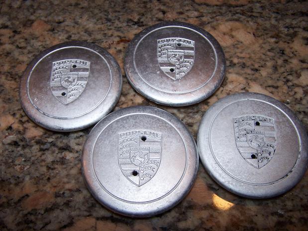
I quick polished one of them. Can you tell which one?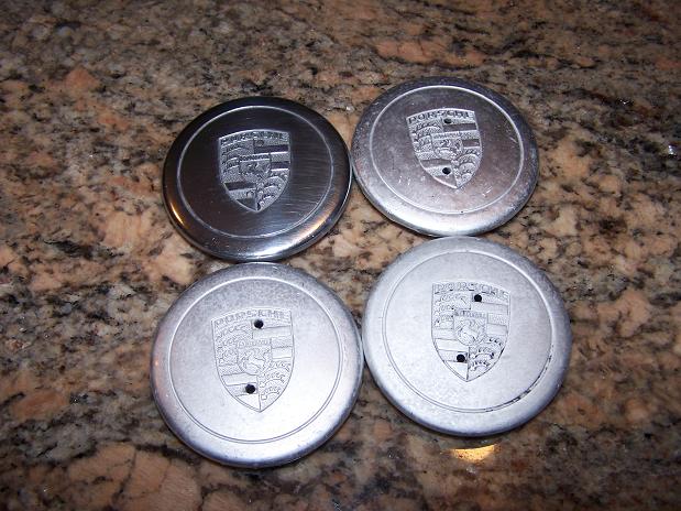
Posted by: Spoke Dec 11 2010, 03:04 PM
Added the decel valve to the engine. I was getting backfiring on high rev (4K RPM) deceleration.
I read on pbanders rennlist FI site that the decel valve was designed to allow more air into the plenum on high vacuum conditions to get the fuel to burn more efficiently. It worked as the backfiring has stopped.
I adjusted the opening to about 15psi vacuum which is a little low since the engine hangs sometimes at 1800 RPM instead of returning to idle. I've adjusted it up a little to allow return to idle speed.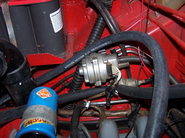
Installed the booster fan for the heater. Getting cold these days. Yep, that's PVC tubing for the warm air guides.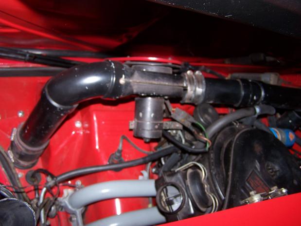
Posted by: Spoke Dec 20 2010, 11:47 PM
Got most of the grind marks off of the one 6x16 wheel. Had to use 80 grit sand paper to get the grind marks out. Damn PO used some sort of power tool to remove the paint/anodizing instead of using chemicals to do the work for him.
Now starting to polish by starting with 220 wet-o-dry sandpaper. Will use 400, 600, 1000, 1500, 2000, then rubbing compound, then polishing compound, then paint.
Attached image(s)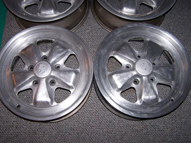
Posted by: Spoke Jan 16 2011, 08:06 PM
Finally got around to doing some more work on the longs. The bottom of the inner longs were completely gone and the PO spot-brazed some patches on connecting them to the top of the patch on the inner long and the rusty floor.
What I plan to do is remove the patches and securely patch the inner long then put on Engman's inner long support kit.
I left the driver seat in the car and the center console so I used some 1/4 inch plywood to protect the interior from welding splatters.
Attached image(s)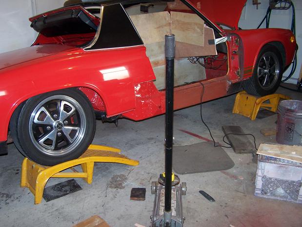
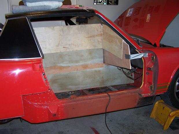
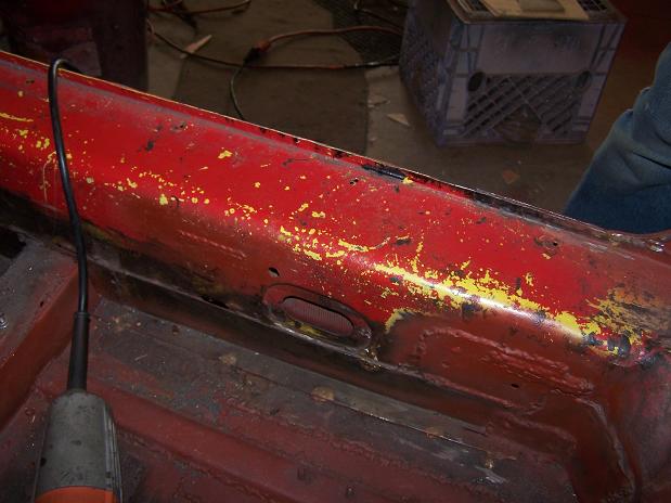
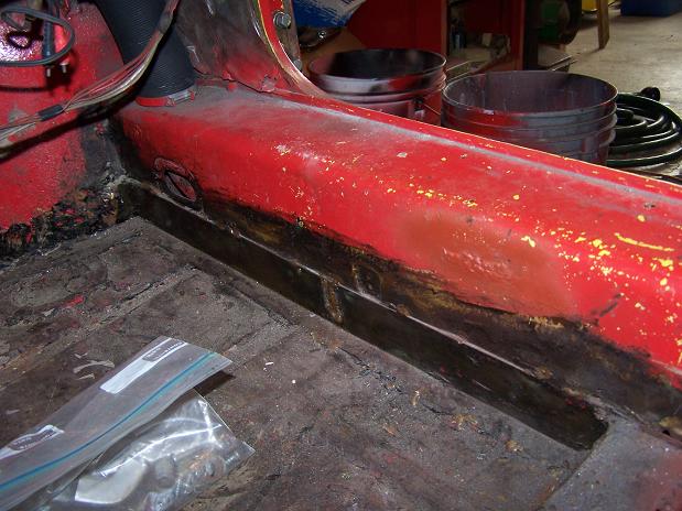
Posted by: Spoke Jan 16 2011, 08:22 PM
Got the first patch off. Lots of rust and rocks inside the longs. The top of the outer patch piece was never closed up so flying rocks were able to get inside the long along with water. I sprayed as best I could with stop-rust. 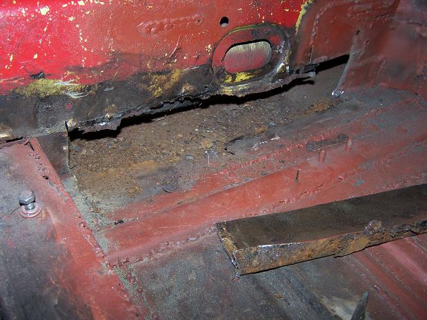
Now it's all cleaned up and primed for the new, stronger patch. The new patch will be installed from below and will wrap around to the bottom of the long patch. I cut a slice in the bottom of the long patch.
BTW, the entire bottom and outside of the long are one piece of 16-gauge steel the PO bent and welded where the totally gone part of the outer and bottom long went.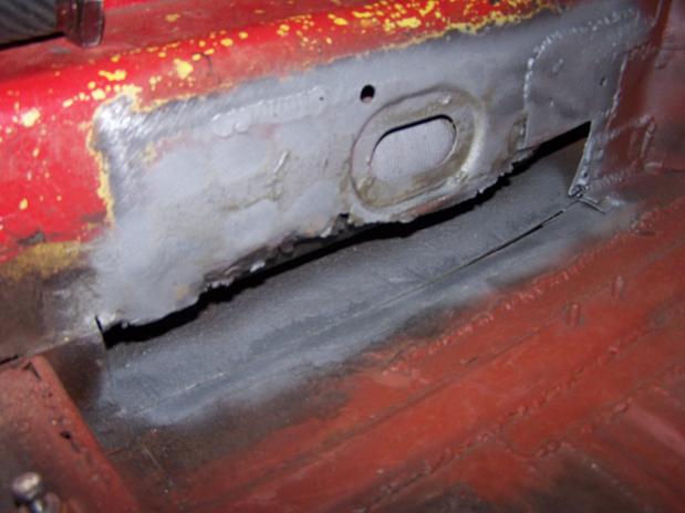
Here's the bottom of the long. This one piece is the entire bottom of the long and wraps up the outside of the long. Such is the fate of a PA 914 rust bucket.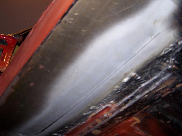
Here is the new patch cut, drilled and primed and ready to be welded in. Unlike a lot of guys who would've cut out all the PO's patches and put in new steel, I have no desire to start over from that point. With the PO's patches, the car was ok solid, not great. The work I've done has really solidified the chassis so far.
I want to drive my 914, not work on it for years. I had it off the road for 2 years changing the engine and tranny. I couldn't fathom taking it off the road for another 2 years to put all new steel in the longs. I know it's not stock but it's getting pretty stiff (That's what she said - Michael Scott) with all the new patches.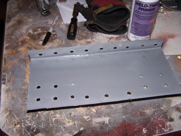
Posted by: Spoke Jan 23 2011, 11:17 AM
First patch is welded in.
Attached image(s)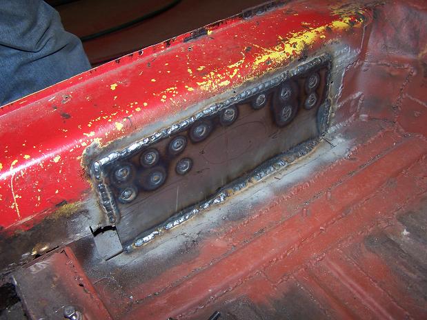
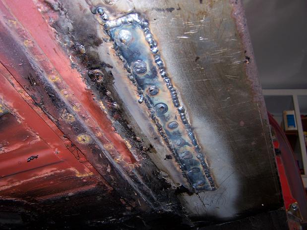
Posted by: Spoke Jan 23 2011, 10:13 PM
Finished polishing the new wheels. Not quite Ed Reed shiny but shiny enough for me. Will clean them up and paint the background.
Attached image(s)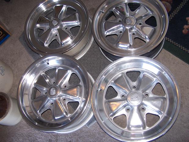
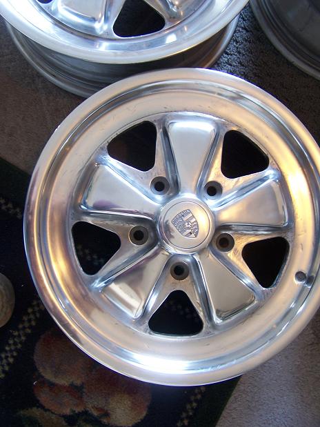
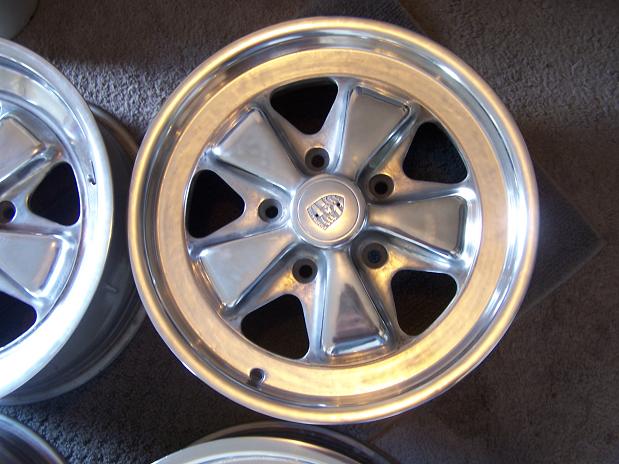
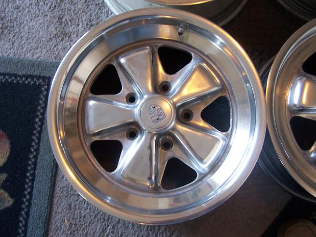
Posted by: Spoke Jan 31 2011, 09:57 PM
Continuing to reinforce the inner long on the passenger side. The entire long was rusted out on the bottom.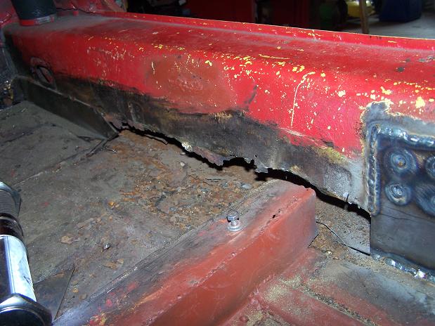
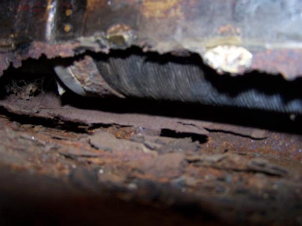
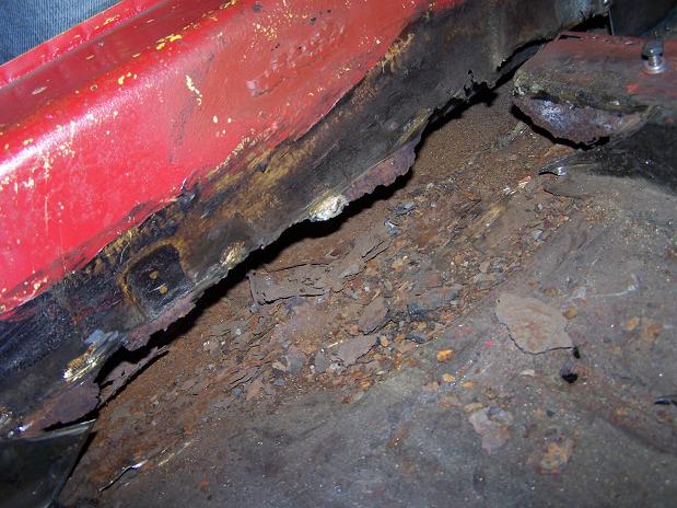
Here's the piece that was brazed on and went behind the center brace.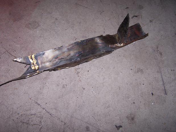
Posted by: Spoke Jan 31 2011, 10:13 PM
Got the center plate welded in. Now to work on the front plate. The long was rusted out all the way to the wheel well.
Attached image(s)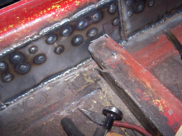
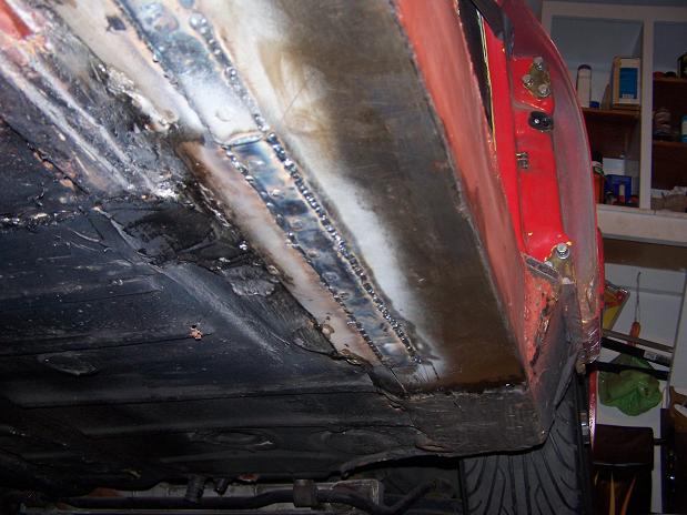
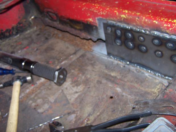
Posted by: Spoke Jan 31 2011, 10:16 PM
Got the front patch panel welded in. The inner long will be further strengthened by Engman's inner long kit. But I have to do the same thing to the driver side.
Attached image(s)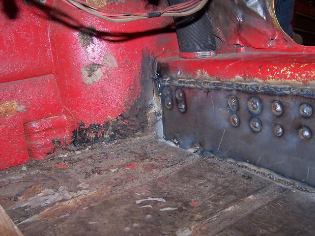
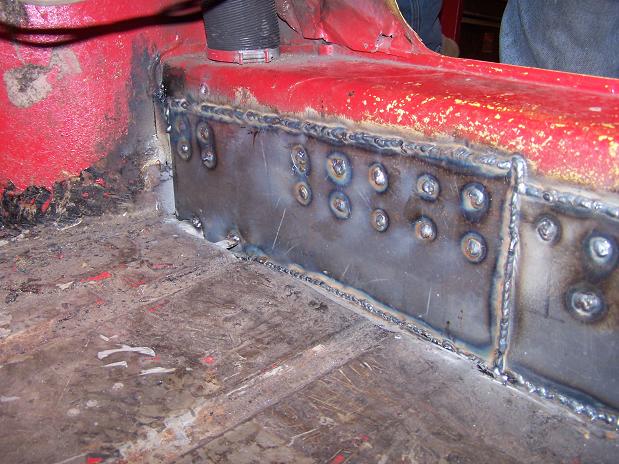
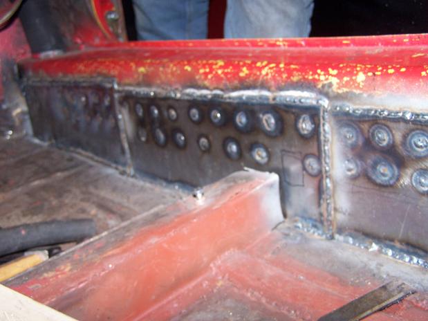
Posted by: Spoke Feb 18 2011, 10:15 PM
Added one piece on to tie the inner long patch to the wheel well.
Attached image(s)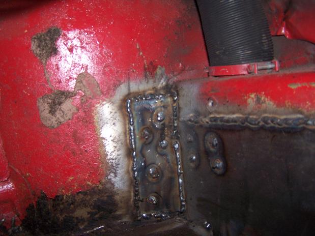
Posted by: Spoke Feb 18 2011, 10:20 PM
Had a couple of holes in the floor so I cut out most of the rust in that area.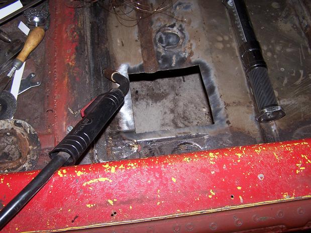
Made a new piece just like the old one (except with no rust).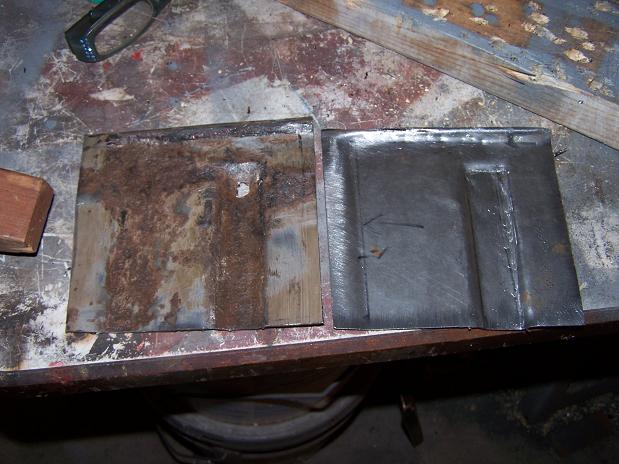
And all welded in.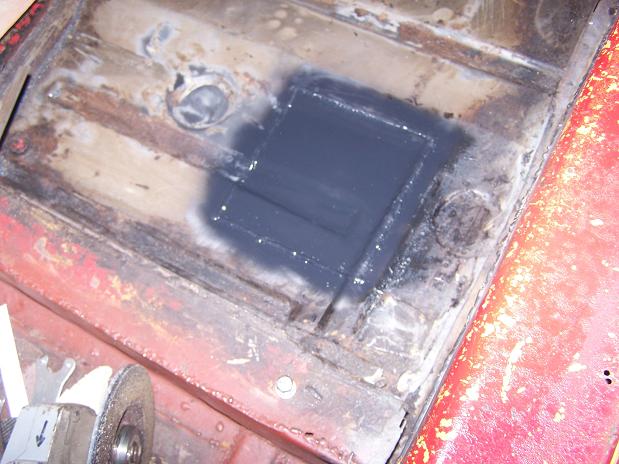
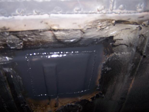
Posted by: Andyrew Feb 19 2011, 10:04 PM
Nice patchwork! Good looking welds!
Posted by: Spoke Feb 21 2011, 11:23 PM
Very inspirational.What tools are you using to shape the metal? Tin Snips, Hands, hammer, Brake?
Thanks, all the metal I'm adding will require me to put a bigger engine in it later.
I've been using the angle grinder to cut the steel as to not deform it with snips.
Then using various fender hammers and my vice to bend the steel in the right places.
Posted by: Spoke Feb 21 2011, 11:26 PM
Got the Engman's inner long welded on the passenger side. Covers up all those patches on the longs.
Attached image(s)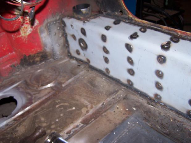
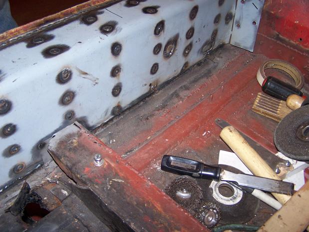
Posted by: Spoke Feb 21 2011, 11:28 PM
This access plug was all bent up and loose so I straightened the floor and plug and welded it on.
Attached image(s)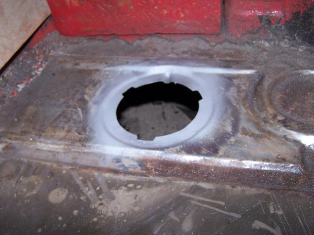
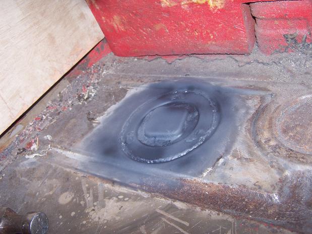
Posted by: Spoke Feb 21 2011, 11:31 PM
So I just noticed this patch that was brazed on. Off with the patch and will weld in a new piece. Also need to finish attaching the cross member to the inner long.
Attached image(s)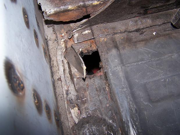
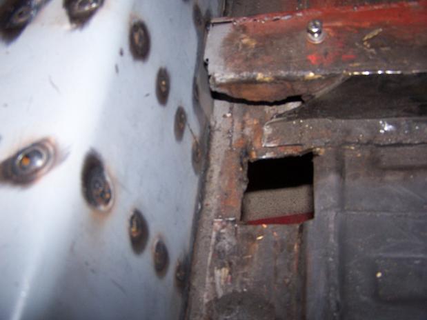
Posted by: Root_Werks Feb 22 2011, 02:30 PM
Nice, you'll really like the inner long kit. It makes a big difference.
Posted by: Spoke Feb 25 2011, 08:25 AM
Got the wheels painted. Not really happy with the paint job but it will do for now.
For the rest of the 5-lug conversion, I need to:
- Find late 80's 911 strut/hubs/rotors/calipers (have A-Arm & underbody swaybar)
- Redrill rear rotors (have 5-lug hubs & new bearings)
- 19mm master cylinder
- Tires
- Roll the rear fenders for the 7x16 wheels
Attached image(s)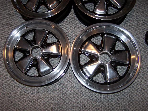
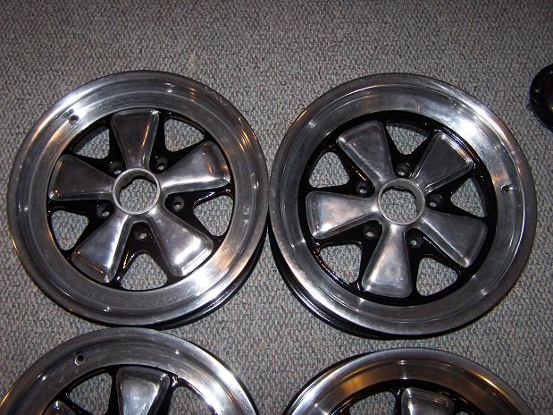
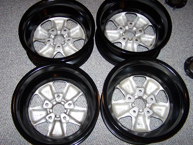
Posted by: Spoke Feb 28 2011, 10:14 PM
Found another weak spot in the floor and cut it out.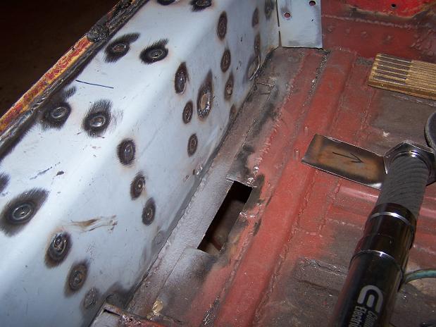
Patched the hole and the small strip of floor next to the long.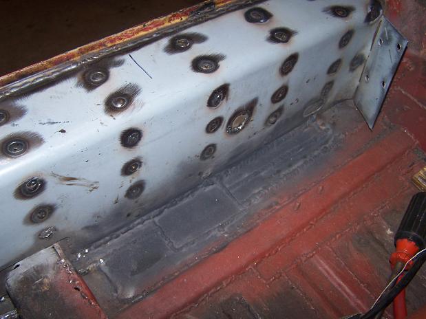
Also patched the hole in front of the crossmember.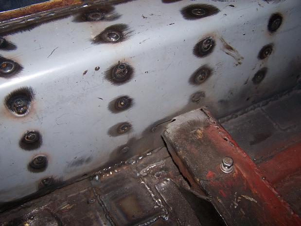
Posted by: Andyrew Mar 1 2011, 09:20 AM
The wheels look great!
Nice patch work! What ga steel are you using? 14ga?
Posted by: Spoke Mar 1 2011, 10:19 AM
The wheels look great!
Nice patch work! What ga steel are you using? 14ga?
Thanks. Compared to what they looked like when I got them, they turned out fantastic. I can't wait to 5-lug the car and mount them.
I'm using 18ga on the floor and body panels and 16ga on the longs. I have a big piece of 14ga that I will put on the outside of the long for further reinforcement.
Posted by: Spoke Mar 2 2011, 11:29 PM
Finished up all the small pieces of the floor next to the inner long.
Also tied in the crossmember.
The passenger side floor is now done unless some more rust-through holes show up.
Attached image(s)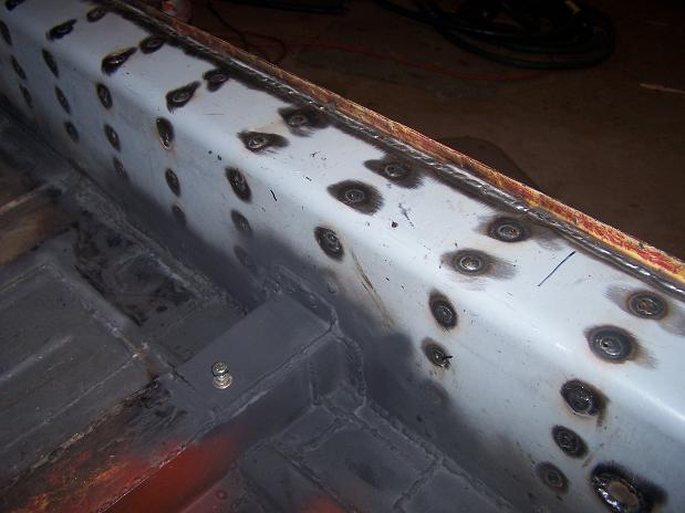
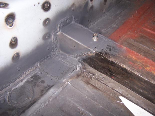
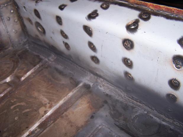
Posted by: Andyrew Mar 3 2011, 10:15 AM
Wow 18ga really? I didnt realize the floors were so thin.
You really think you'll need another bit of reinforcement after the engman kit? I have the engman kit and it is pretty damn solid. The next step is tieing in the suspension points to the long IMHO
Posted by: Spoke Mar 3 2011, 11:48 AM
Wow 18ga really? I didnt realize the floors were so thin.
You really think you'll need another bit of reinforcement after the engman kit? I have the engman kit and it is pretty damn solid. The next step is tieing in the suspension points to the long IMHO
I don't know about what gauge the floors are. I guessed at 18ga since the longs are 16ga I think.
I was thinking about how to better tie the front of the long to the door pillar. Any suggestions?
Posted by: Andyrew Mar 3 2011, 02:23 PM
Hmmm that is a good question, I havent looked at that piece in a while, you got any pics of the area?
Posted by: Spoke Mar 13 2011, 09:08 PM
Cleaning up the front portion of the long. Found 2 holes so time to cut it open.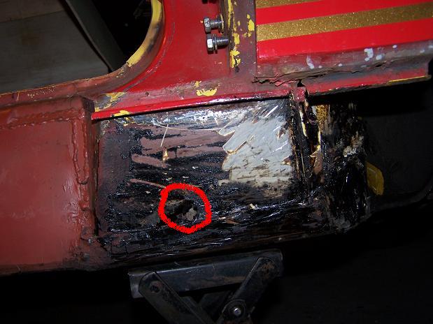
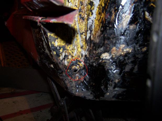
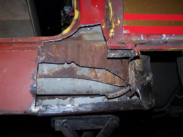
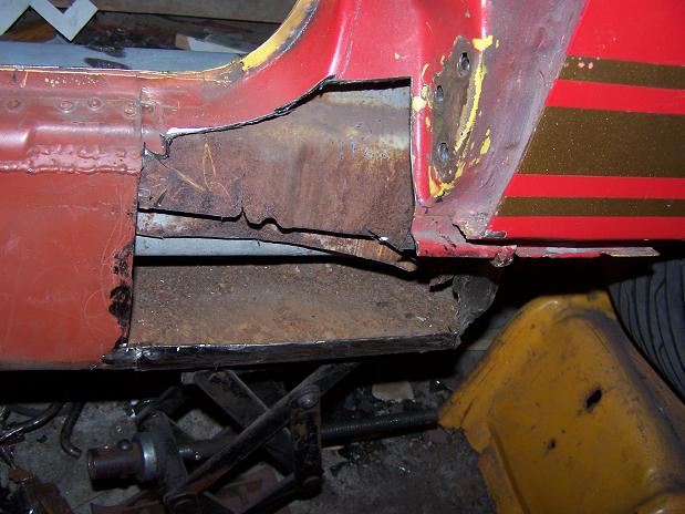
So this is what is left of the bottom of the long.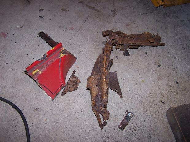
Posted by: Spoke Mar 13 2011, 09:10 PM
Prepped the area for new metal.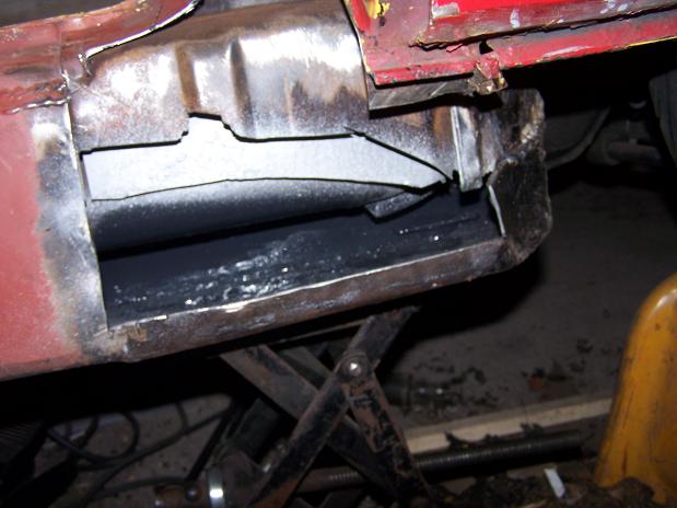
Center support done.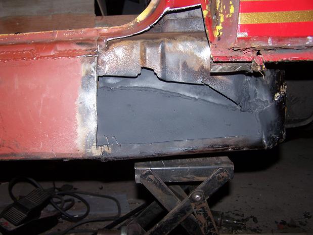
Outer long is much more solid now.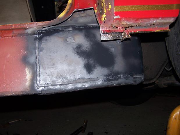
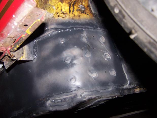
Posted by: Root_Werks Mar 14 2011, 09:55 AM
Posted by: Spoke Apr 3 2011, 07:12 PM
Where's that home-made tool thread? Here's my temporary metal break. I scored this 14 gauge piece so it would bend easily.
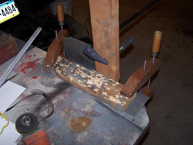
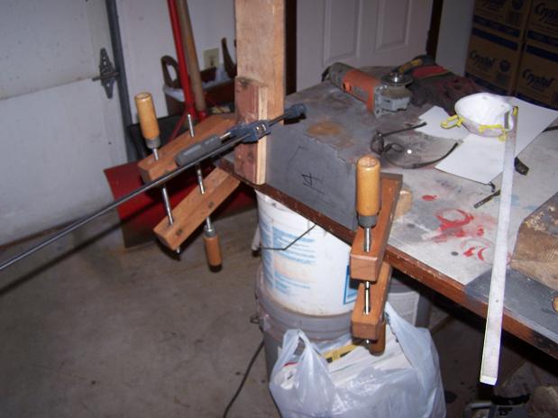
Finished piece ready for installation.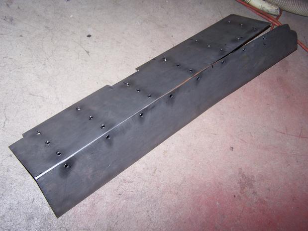
Posted by: Spoke Apr 3 2011, 09:05 PM
14 gauge outer clam shell all welded on.
Attached image(s)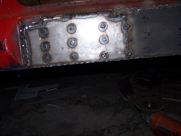
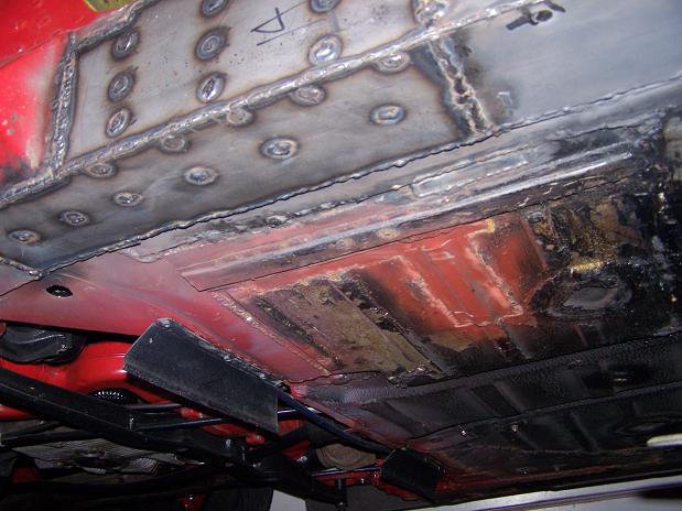
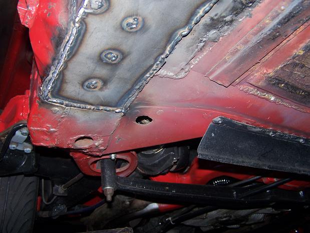
Posted by: Spoke Apr 3 2011, 09:11 PM
Putting the door support back together.
The support plates will help bind the support to the bottom piece.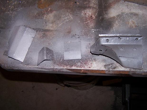
I put a support piece from the top of the long to the door support.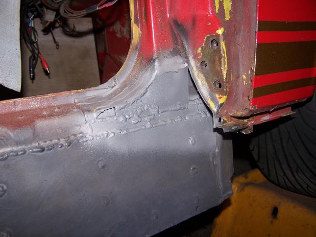
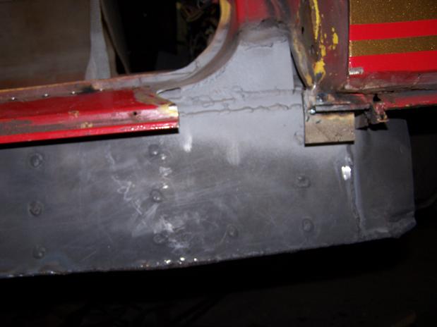
Posted by: Spoke Apr 3 2011, 09:14 PM
Finished the door support. Used 16 gauge for all new metal.
Attached image(s)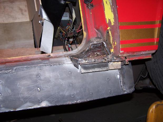
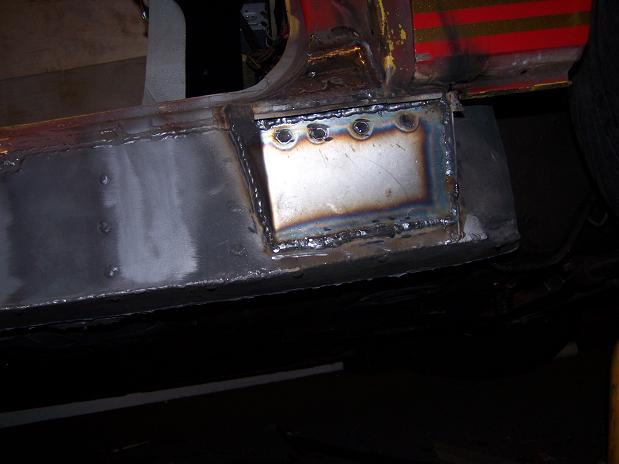
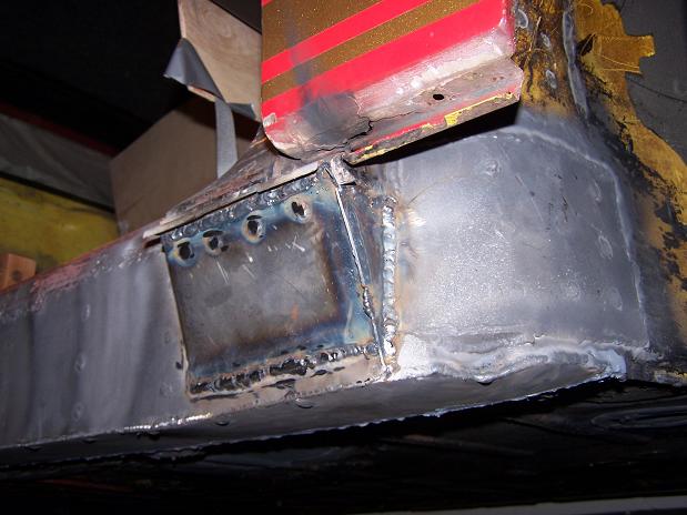
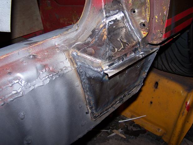
Posted by: Spoke Apr 3 2011, 09:23 PM
For the finishing touch, I put ribs on the outer long. For now I'm finished welding on the passenger long.
Next steps:
o Clean up welds on long.
o Sandblast the rear fender replacement. It will need some new metal.
o Install fender replacement.
o replace sill.
o Paint outer long and door jamb.
Attached image(s)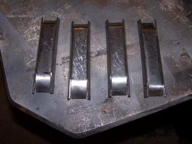
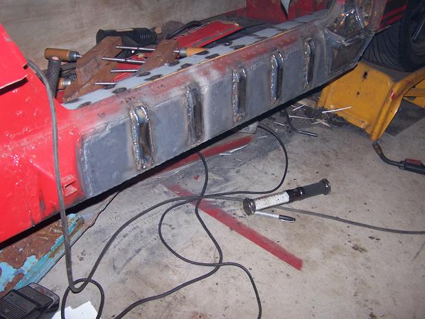
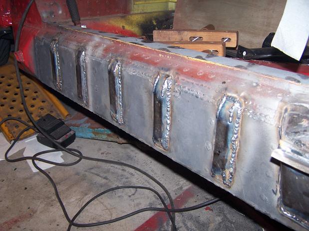
Posted by: Andyrew Apr 4 2011, 10:23 AM
Thats a shitload of metal there!
The Ribs were an interesting idea!
Posted by: FourBlades Apr 4 2011, 11:22 AM
Wow, that is a lot of welding!
Very nice work.
John
Posted by: Spoke Apr 4 2011, 09:21 PM
Sandblasted the fender replacement. I knew it was rusted through. Now the damage is obvious. The whole corner of the fender needs replacing.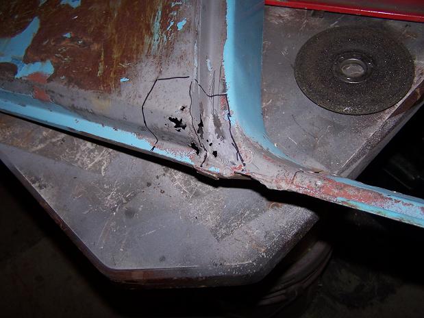
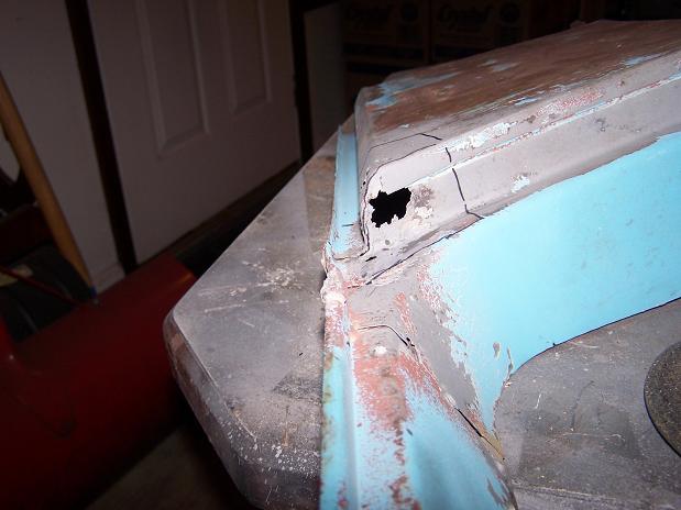
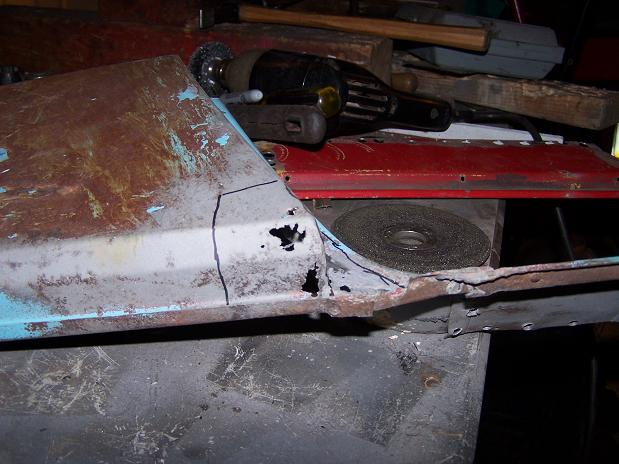
I will make 4 pieces to do the repair. This is the base plate. Next will be the bottom lip, then the door jamb, then the fender and underside wraparound.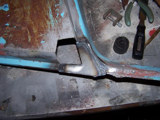
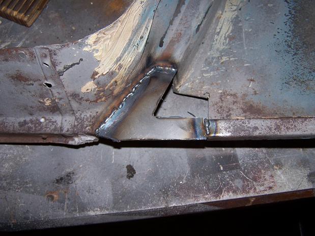
Posted by: Spoke Apr 5 2011, 10:21 PM
My latest purchase. Not bad for $150 delivered to my home.
This is from a 74 and has the 3-inch front calipers.
Rotors will likely need replaced. Front calipers will need rebuilt. 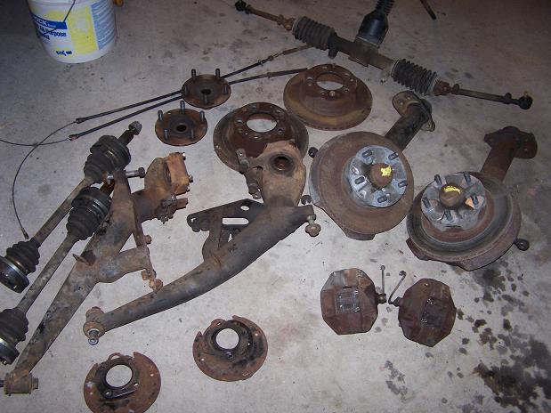
Separate purchase. Saves me from widening and rebuilding my existing calipers. These look too nice to use.
Posted by: Andyrew Apr 6 2011, 09:11 AM
With the spacers for vented rotors? Nice!!
Talk about a score!
Posted by: Spoke Apr 6 2011, 09:02 PM
Bottom lip is welded on.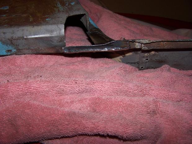
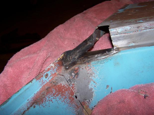
Now the door jamb piece.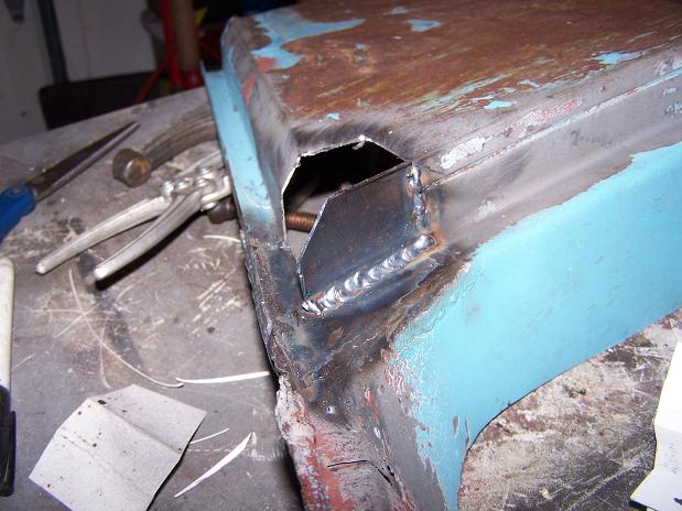
Finally the fender piece. Too late tonight to grind the welds down. Good as new.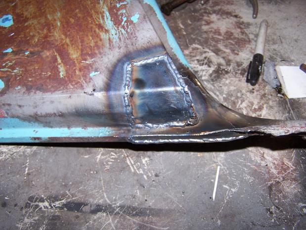
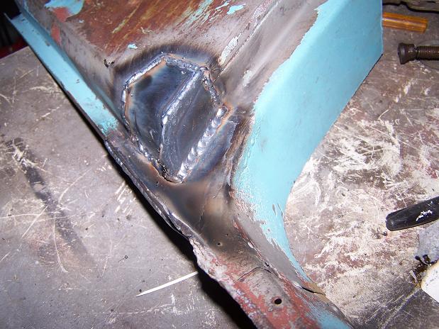
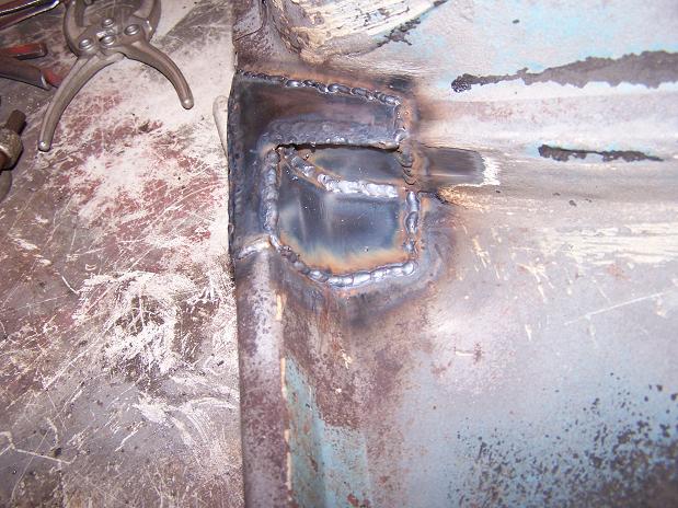
Posted by: Spoke Apr 8 2011, 09:02 PM
Got around to grinding down the welds on the fender. The repair came out very good.
Attached image(s)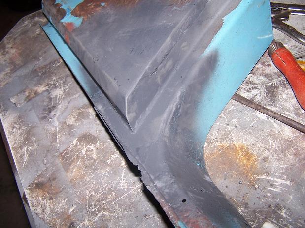
Posted by: Spoke Apr 8 2011, 09:05 PM
WTF are these appendages? Any guesses?
Attached image(s)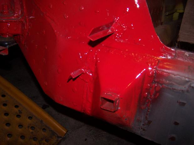
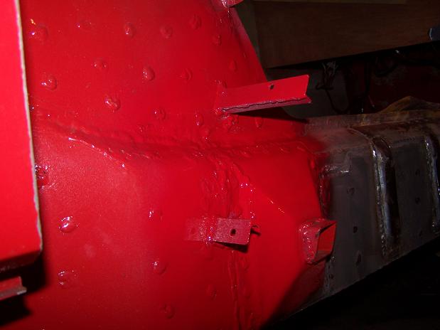
Posted by: Spoke Apr 9 2011, 07:02 PM
One shortcoming of the inner fender well is that all the rocks and debris kicked up by the tires can end up trapped between the rocker panel and the jack point.
With these brackets I'll attach a rock deflector to keep the jack point relatively clear of debris. I'm thinking of using a plastic-type mudflap for the material. Don't really want to use steel.
Attached image(s)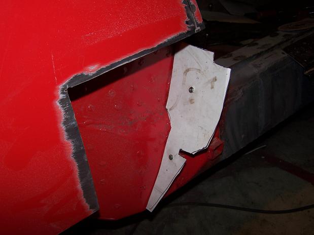
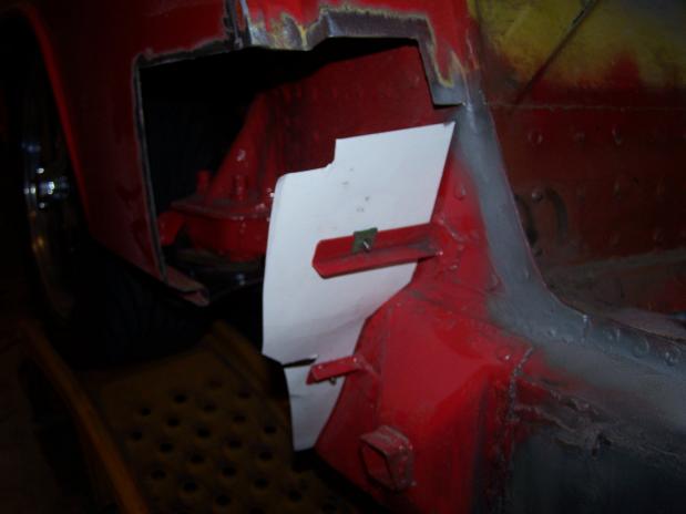
Posted by: Spoke Apr 9 2011, 07:10 PM
Well, with all the work I did to the inner and outer longs, I managed to shrink my car by about 1/8 inch such that the passenger door wouldn't close.
After the accident, the door gap was quite small but today when I mounted the door, it wouldn't close. So I had to shorten the rear fender a bit and push the door jamb back a bit.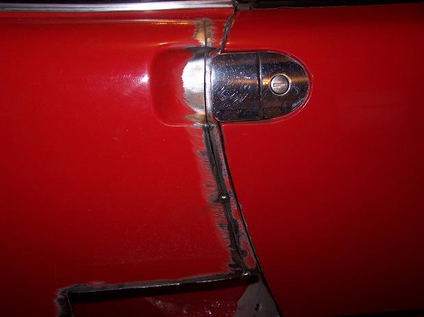
The last piece to attach on the passenger side. I cut the piece to near the right size then used the angle grinder to get it to fit nice. Looks good not to see the big hole in the fender. I bought this piece about 2 years ago.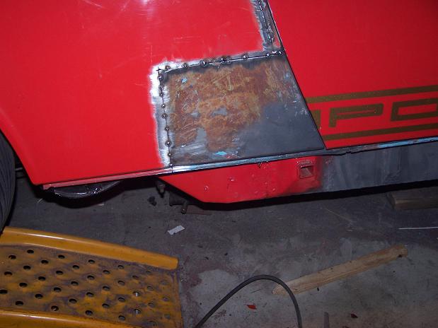
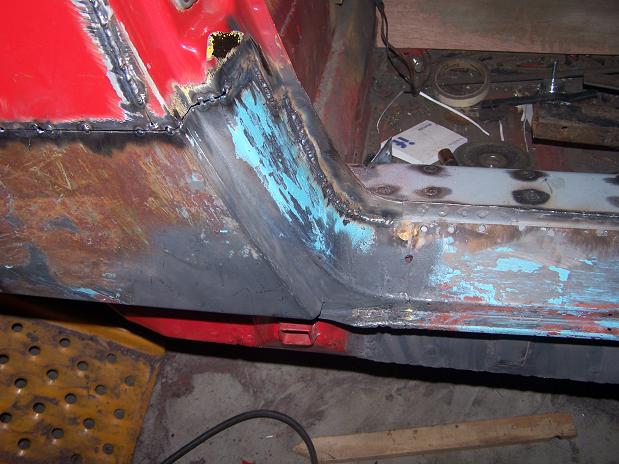
This is the original door sill. I cut off about 5 inches of the back part of this cause it was totally rusted out.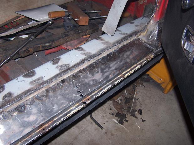
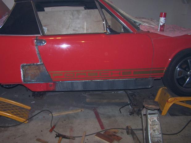
Posted by: Spoke Apr 10 2011, 08:23 PM
The last job for now. Finished attaching the door sill.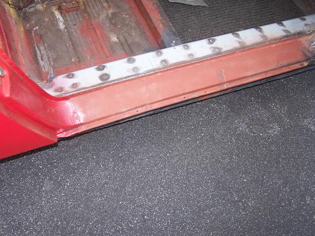
The sill supports are made from 16 gauge steel. 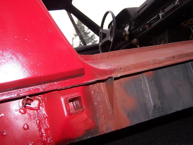
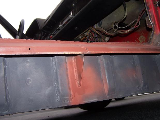
I may have added a lot of steel in my rustoration but I took off 26 pounds of steel, rust, and tar.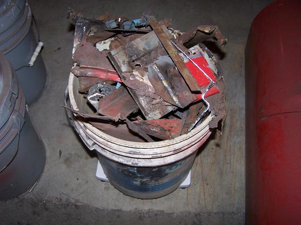
Posted by: Spoke Apr 10 2011, 08:32 PM
The 914 is out of the garage for the first time in 4 months. The metal work is done on the rear fender but bodywork is needed now. The 911 is going in the corner for now and I'll drive the 914 for the time being. 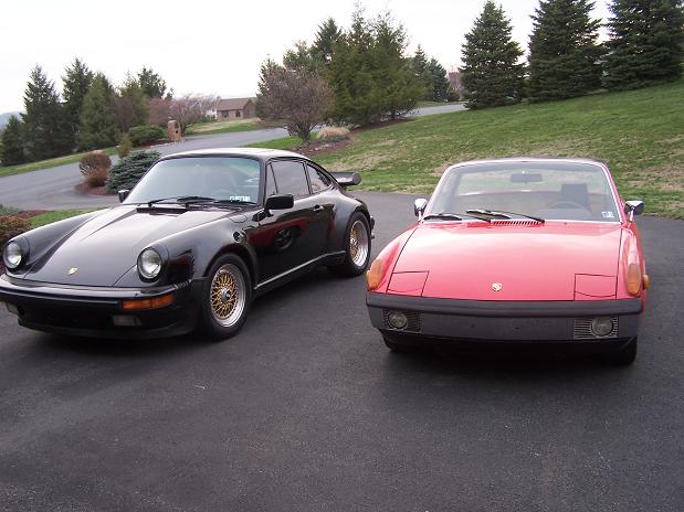
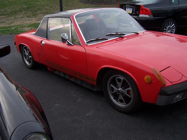
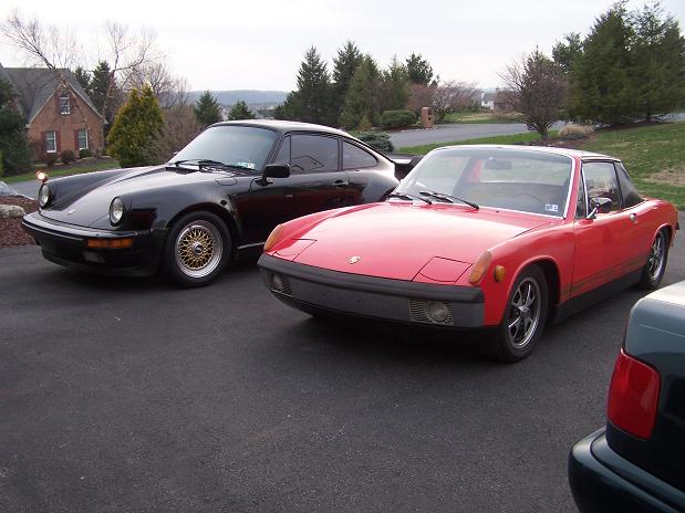
One fat ass and one narrow one.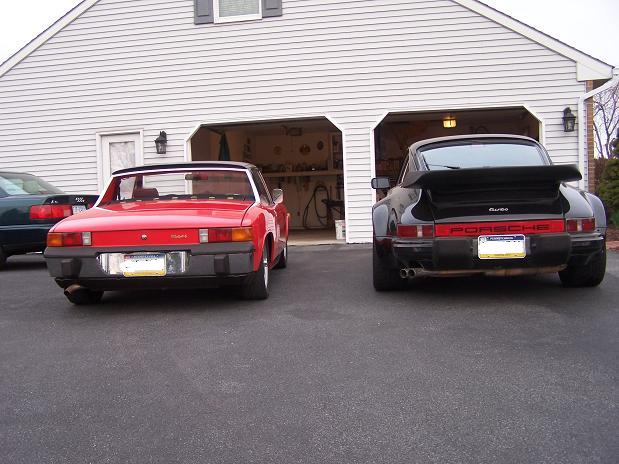
Posted by: 9fourteen Jun 10 2011, 01:58 PM
I see you used weld-through primer on this. How well did that stuff work? Did you always get good welds with it or did you have to remove some of it? What type/brand did you use?
Great job btw. Your project is inspiring me to finally start cutting the rust out of mine.
Thanks,
Don
Posted by: Spoke Jun 10 2011, 03:50 PM
I see you used weld-through primer on this. How well did that stuff work? Did you always get good welds with it or did you have to remove some of it? What type/brand did you use?
Great job btw. Your project is inspiring me to finally start cutting the rust out of mine.
Thanks,
Don
Thanks, and BTW,

I don't know what brand I used. The welding wasn't bad through the primer. It does smoke a bit but you do want primer between all the layers of steel or behind panels you can't paint after installation.
Posted by: porsche_dreamer Jun 10 2011, 10:09 PM
Looks like some good progress. The turbo doesnt look to bad either!
Posted by: Spoke Jul 11 2011, 09:08 PM
Got my front M-calipers back from Eric Shea. Wow!
Brake calipers front and rear ready to go for 5-lug conversion. Just need to get new rotors, and sell my 911 rear hubs & half shafts.
Attached image(s)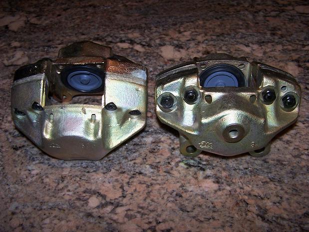
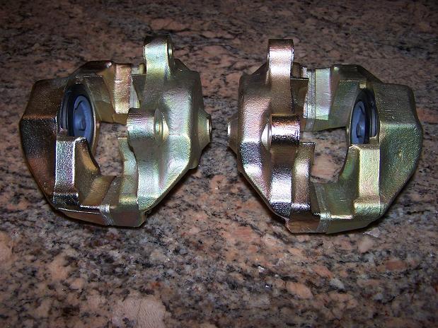
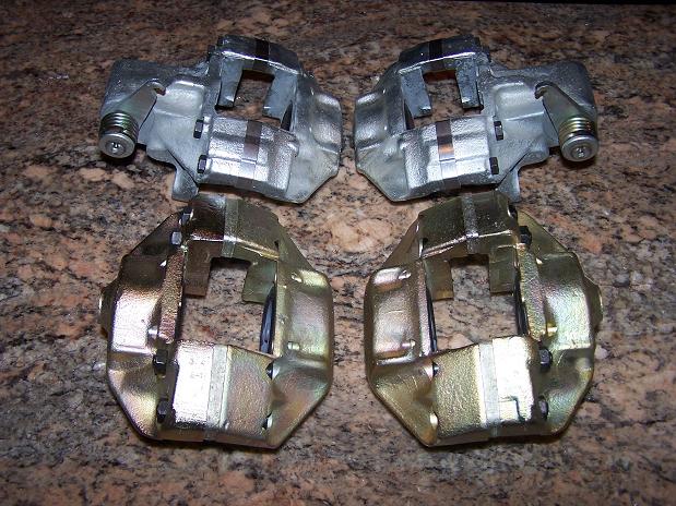
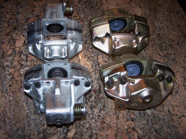
Posted by: fitsbain Jul 27 2011, 08:15 AM
Glad to see that corner came to good use.
Sorry it was so rusty.
Posted by: Spoke Feb 11 2012, 07:50 AM
Glad to see that corner came to good use.
Sorry it was so rusty.
The piece was still 100x better than what I took off.
Posted by: Spoke Feb 11 2012, 07:52 AM
Any tips for dislodging the spline? It seems to be rusted on. I've been soaking it in Aero Croil.
Attached image(s)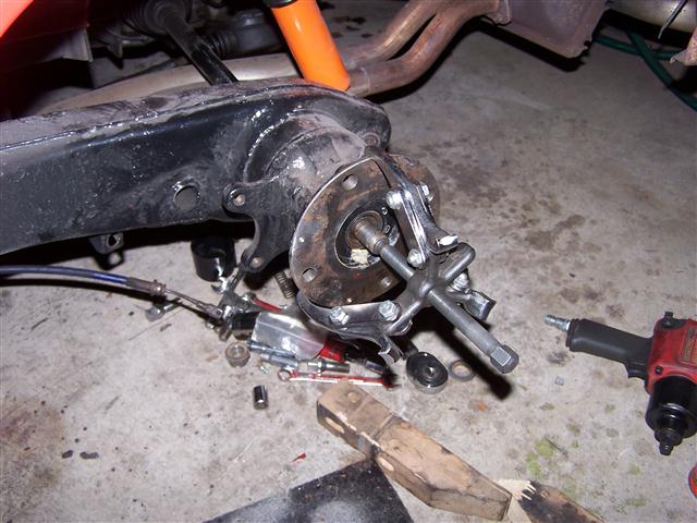
Posted by: okieflyr Feb 11 2012, 09:34 PM
I can't see that the axle is disconected on the trans side (it should be) but you can thread the axle nut back on upside down and flush with the end, and then use a BFH to break it loose back through the hub.
Posted by: Jeffs9146 Feb 11 2012, 09:58 PM
You have to remove the trailing arm to get it out any further!
I just did this last month. You wont be able to pull the hub out of the bearing that way. You can remove the axcel and then pound out the hub and bearing but I found it easier to just remove the trailing arm and do it on the bench. That way you can leave the axcel, CV's and stub still attached and slide it back into the hub when you put the arm back on!
Here is the motivational photo!!!
Attached thumbnail(s)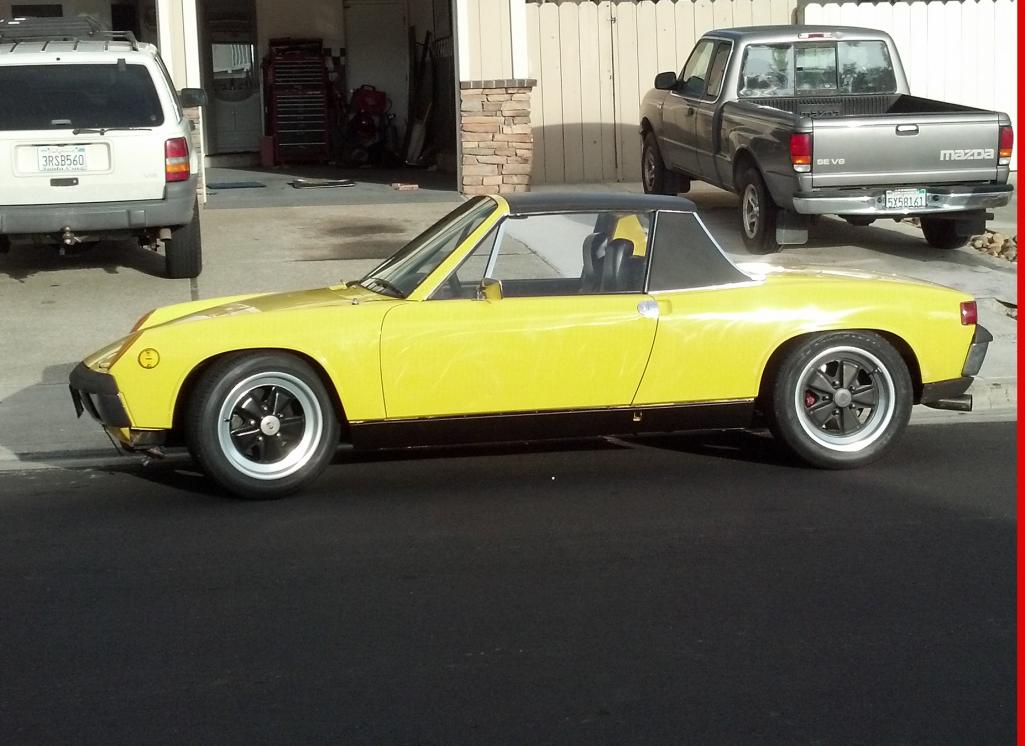
Posted by: Spoke Mar 1 2012, 08:05 PM
I finally dislodged the spline. Aerocroil, time, and a BFH did the trick.
Correct about the axle still connected to the trans; there was still plenty of play between the CVs to loosen the spline from the hub.
With my newly unemployed status, I put the rear end back together again and will focus on some longitudinal rust repairs since I have plenty of metal, cutoff wheels, gas in the welder tank, and time on my hands.
Posted by: Spoke Mar 1 2012, 08:19 PM
Time to repair the driver side interior floor and inner long. The goal is to make the car as tight as possible spending the least amount of money.
The car has a reconstructed title after the wreck (see post #1) and is questionably not worth a whole bunch. The floor and longs should be replaced in their entirety but I will cut out the bad and replace with new steel like I did on the passenger side.
Note the trianglular replacement panel in the bottom. This was done by the PO.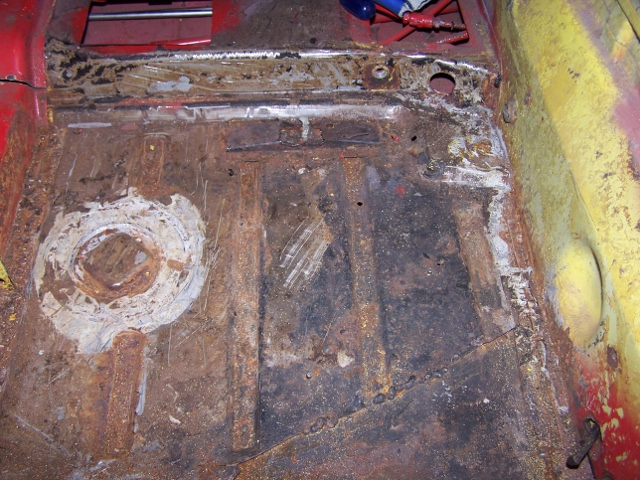
I will continue to rebuild the inner long with panels such as the one shown here in 16ga steel. The PO placed a 16ga panel under the rotted out long and up the outside of the long. I will tie into this with about 2 or 3 of these plates, then cover with an Engmans inner long kit.
The gold flakes are from grinding some braising away.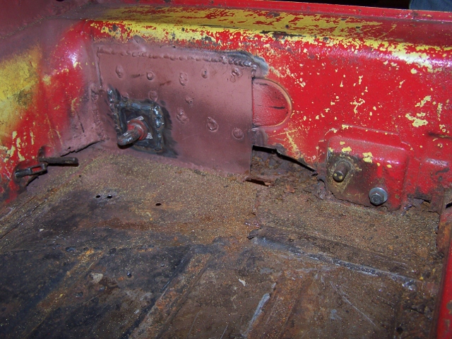
Not much left of the crossmember. It's going away too.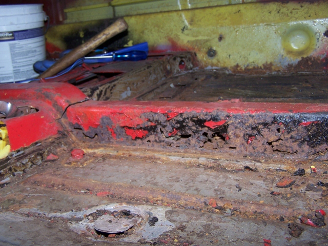
Note the tie plate on the inner long to the floor. This is braised in and will be removed.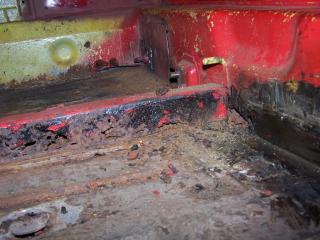
More of the braised plates.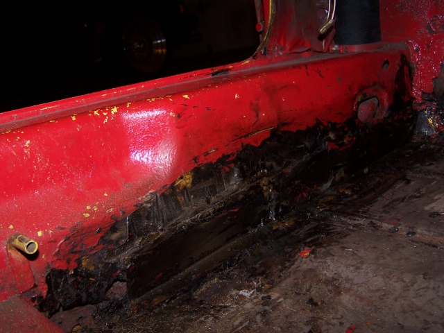
Notice the hole to in the wheel well to the right.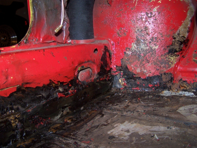
Posted by: Spoke Mar 1 2012, 08:25 PM
Like the passenger side, the inner long is completely gone all the way along the interior.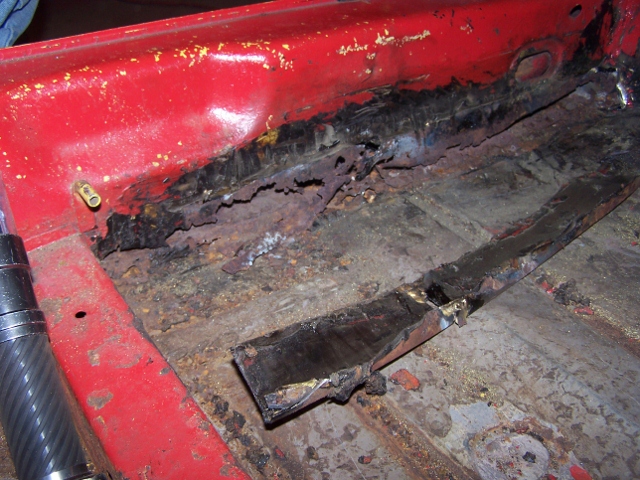
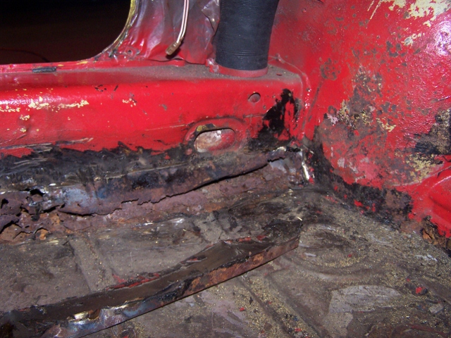
Had to remove the E-brake mount.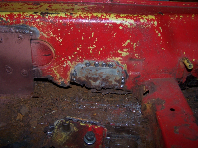
The E-brake mount is toast. I will cut off the bolt and sleeve and make a new bracket.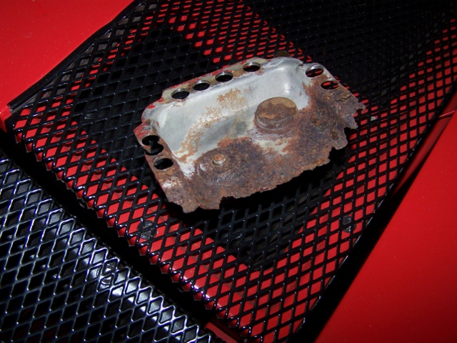
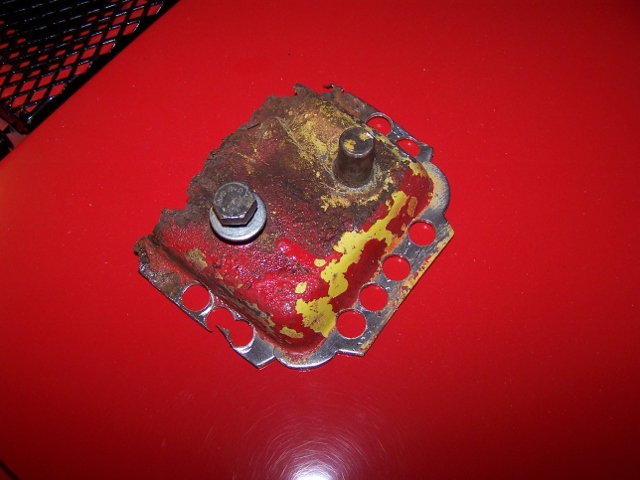
Posted by: Spoke Mar 3 2012, 04:11 PM
Cleaned out the bottom of the long. Prepping for the replacement pieces.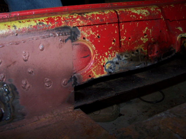
Removed all the rusted pieces and rusted floor.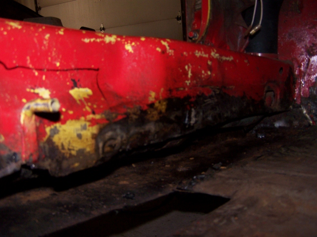
First replacement piece ready to be welding.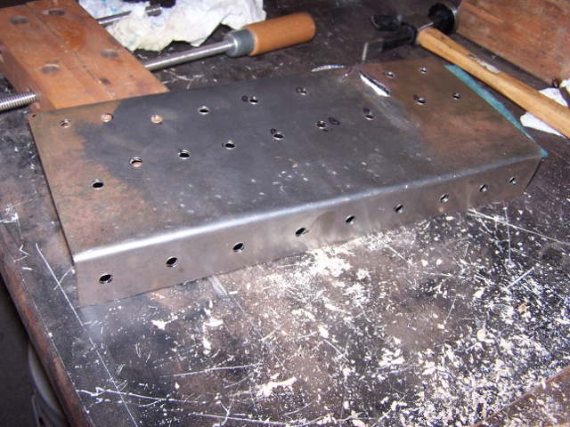
Posted by: Spoke Mar 5 2012, 11:02 PM
Rebuilding the inner long
Attached image(s)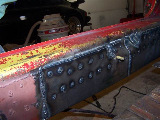
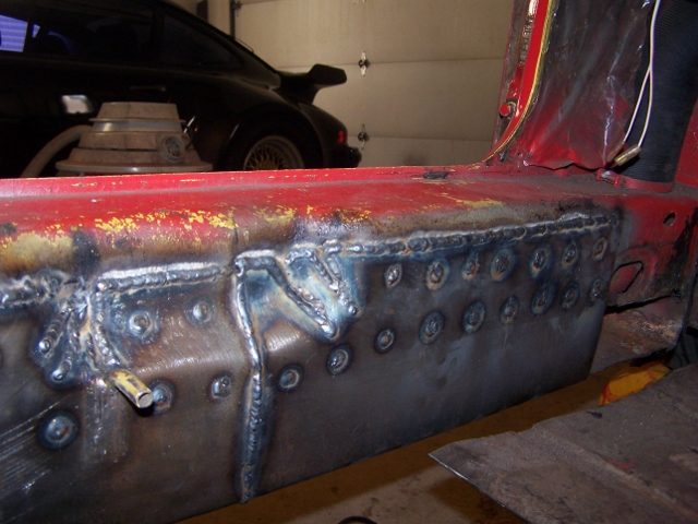
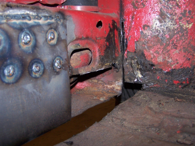
Posted by: Spoke Mar 16 2012, 06:20 AM
Prep for adding the last inner long piece.
I cleaned up all the tar and rust proofing. The PO had braised the metal in. The new piece will come through the wheel well and attach to the existing 16ga long metal.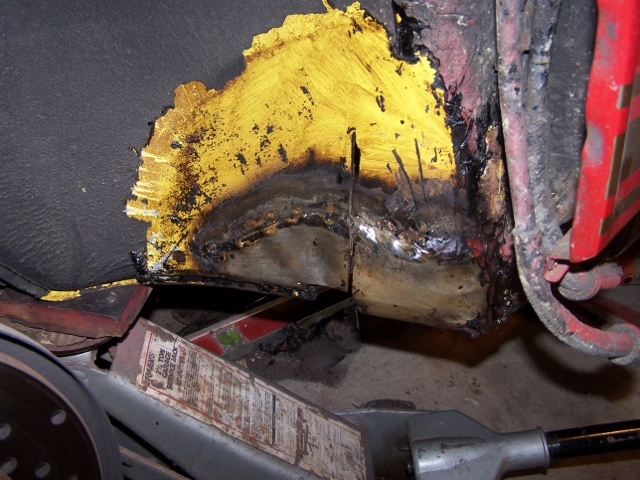
The part of the patch to the inside of the wheel well was hiding some ugly rust. How shocking! 
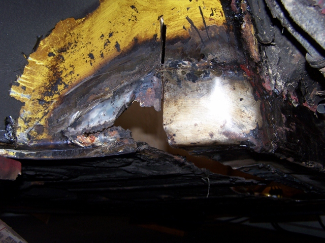
The new inner long material installed. I ground down as much of the braise on the existing long metal and welded.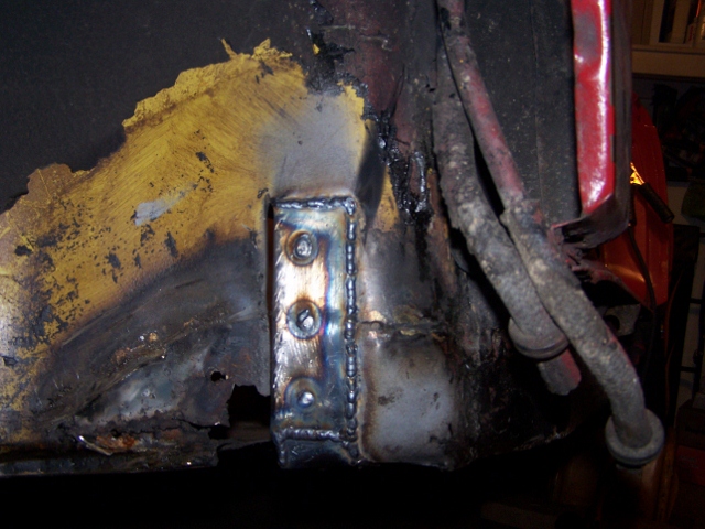
Inner long is now solid metal from front to rear.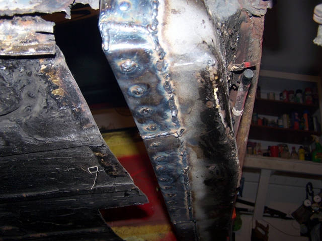
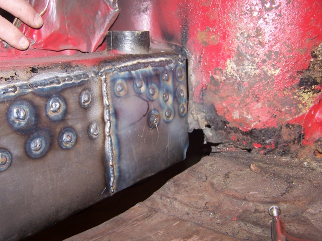
Posted by: Spoke Mar 16 2012, 06:29 AM
Fabricated a patch for the drivers side floor.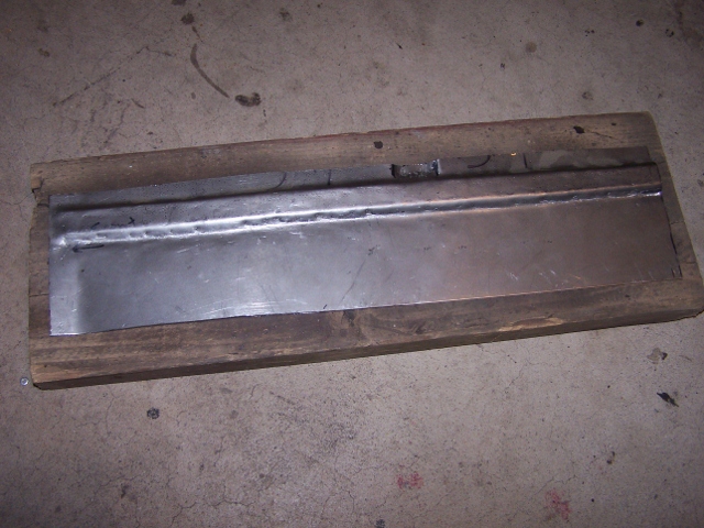
The channel is raised on the inside and has a piece under the car which is raise to the outside. I decided to weld this bottom piece on the entire length of the channel. I don't think the original bottom piece spanned the entire channel.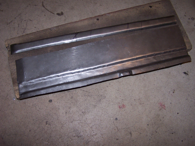
The 2 pieces welded together. To protect the inside of the channel brace, I poured cream-colored lacquer that I had laying around which of course overflowed and got on everything.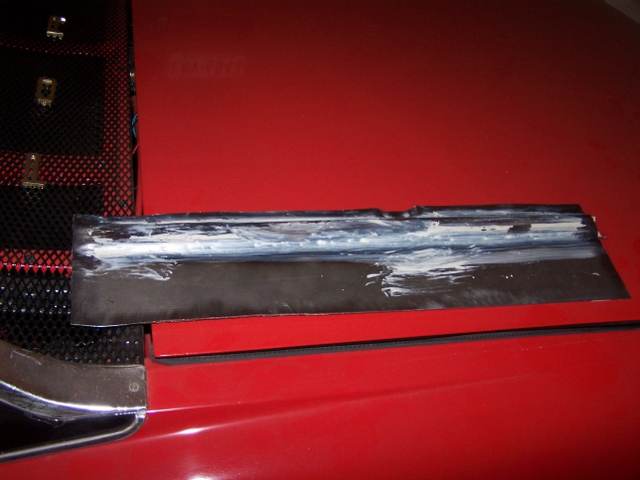
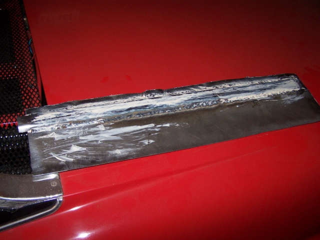
A pic of the inside of the channel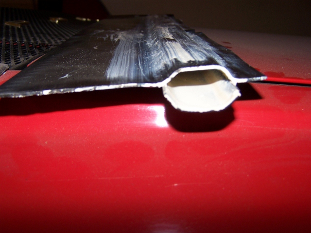
Welded in place.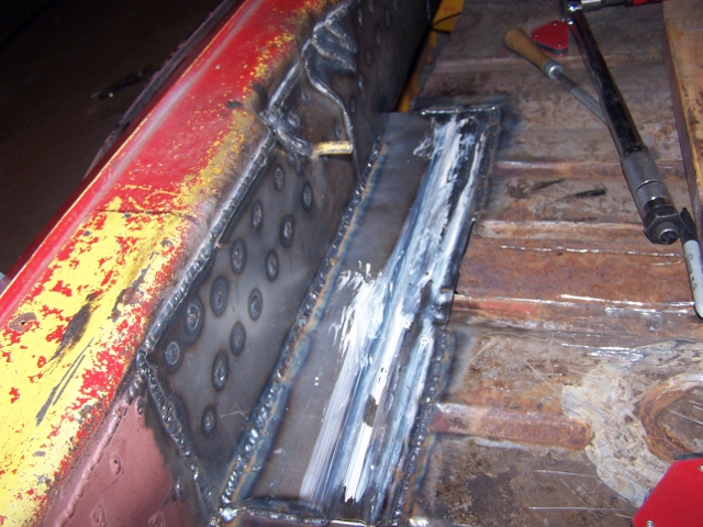
Posted by: Spoke Mar 17 2012, 09:30 PM
OK, so I cut out all the rusted material on the wheel well. The problem is the wheel well piece is a complex piece with several bends. So I will make this 2 pieces; one with the concave bends and tack weld surface with the floor, and the other with the simple flat concave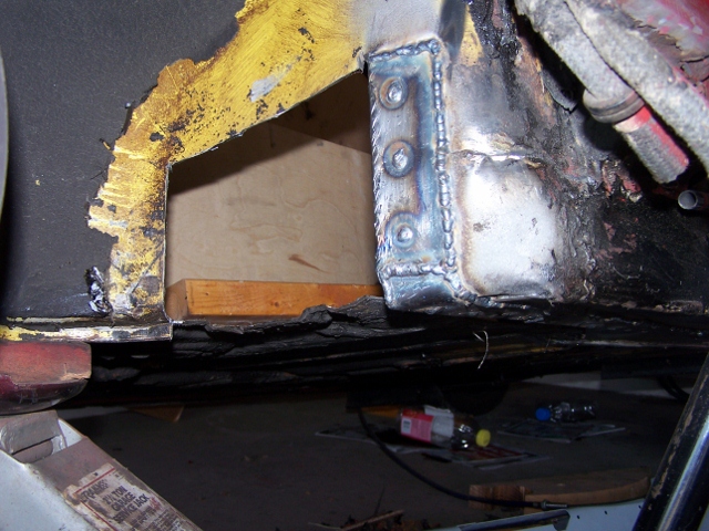
This is the first piece with the most complexity. I made the tack weld surface and curves then sliced the metal so to make the concave shape.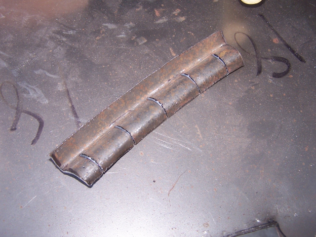
Ready for welding.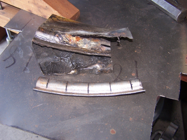
Posted by: Spoke Mar 17 2012, 09:37 PM
The bottom piece welded in place.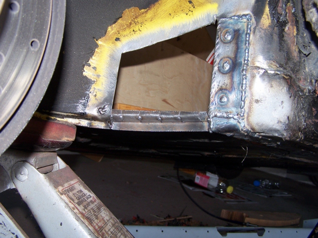
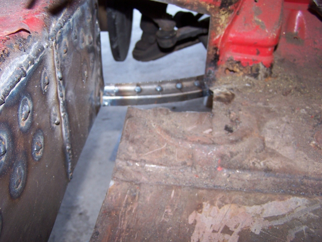
And the upper piece welded into place. Franken914 gets some more stitches and lives yet another day! 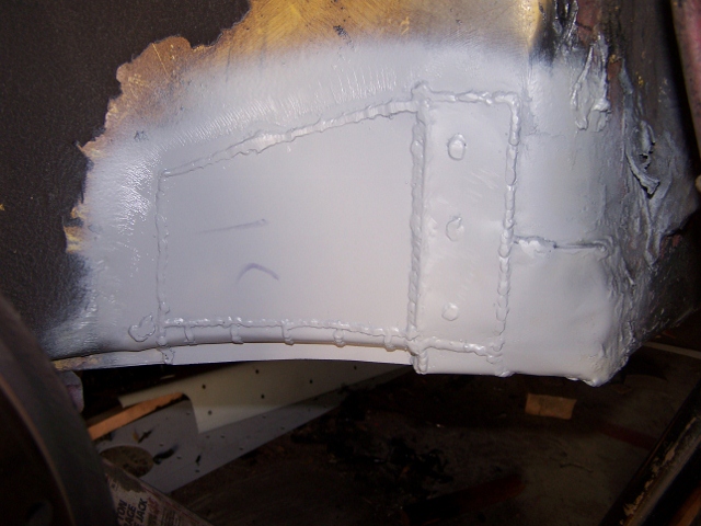
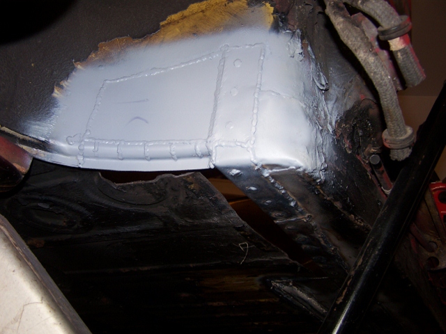
Posted by: jaxdream Mar 18 2012, 09:08 AM
Great work !!!! Keep going !!!
Jack
Posted by: Spoke Mar 24 2012, 08:07 PM
Driver Floor corner piece.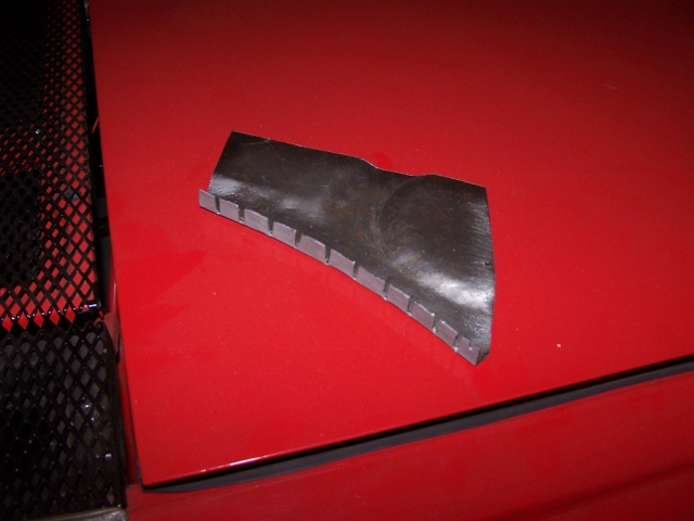
Instead of drilling holes to "spot" weld, I made slots to weld between.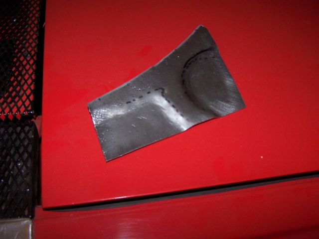
Installed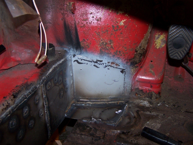
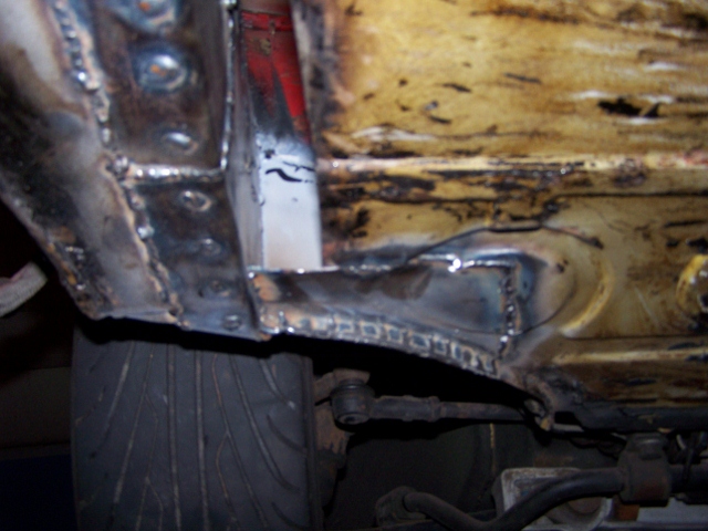
Posted by: Spoke Mar 24 2012, 08:20 PM
I need to replace some of the channels in the floor. I could (and should've) replace the entire floor pan. But then again, I'm a CSOB. I bought enough 18ga metal to do the entire floor for $5 from a local metal shop so I will continue to replace in pieces.
I made channels before by making all the bends one at a time. Quite time consuming. So I made a jig for making the channels. Right now there are 4 pieces:
2 pieces to set the channel width. These mount in a vice and can be adjusted for width.
1 piece to pound the metal into the channel
1 piece to make a channel end.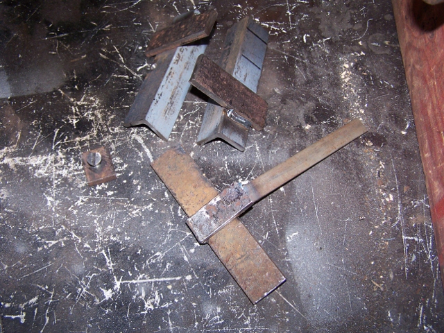
Here are the channel forms in place.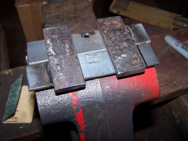
The channel is formed by pounding on the jig where needed.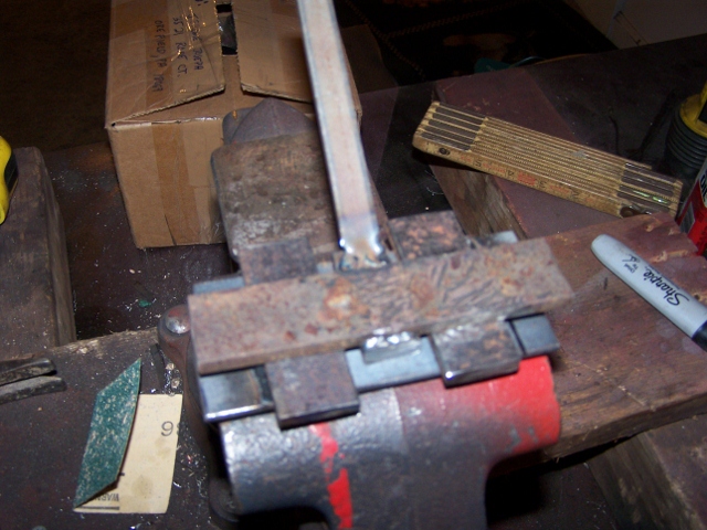
For making the channel ends, this piece can be screwed into the channel form.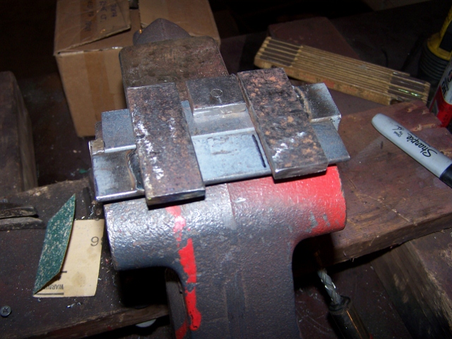
Posted by: Spoke Mar 24 2012, 08:24 PM
This piece will finish the floor next to the long. 2 channels terminate in this piece.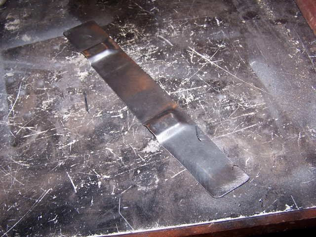
Here the piece is ready to weld.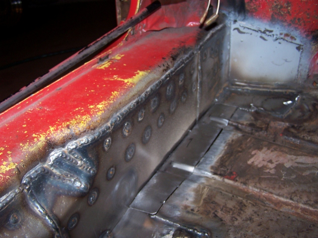
Posted by: Jon Fernandes Mar 24 2012, 10:02 PM
Great work!
Posted by: abnrdo Mar 24 2012, 10:34 PM
Awesome work! Keep plugging away!!
Posted by: effutuo101 Mar 25 2012, 07:48 AM
Very nice!
Posted by: Spoke Mar 26 2012, 03:14 PM
The front channel rusted through in a couple of places so I'll replace the entire channel.
Also rusted is the circular plug so I'll replace this with another smaller channel.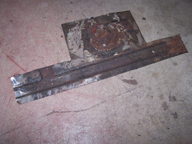
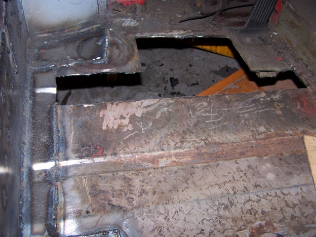
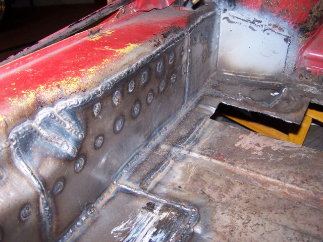
Looks like the original.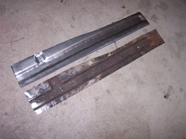
And welded in.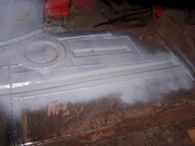
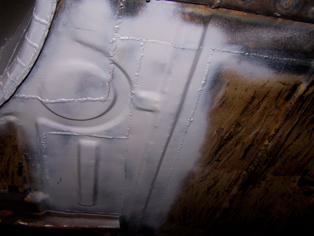
Posted by: Spoke Mar 31 2012, 08:49 AM
The floor under the cross brace wasn't rusted through but was thinned, so time to replace it.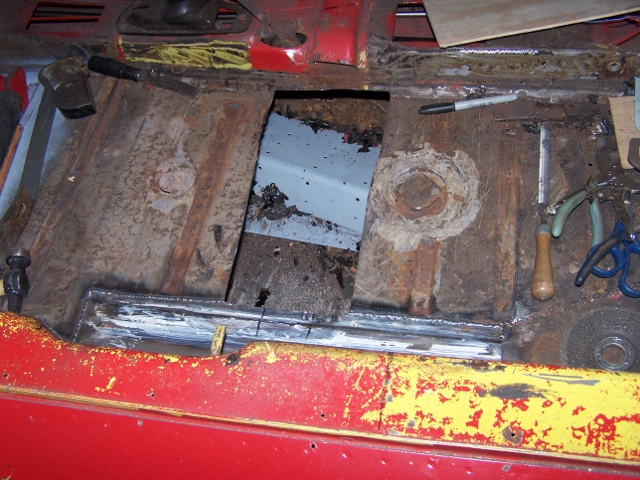
New piece ready to go.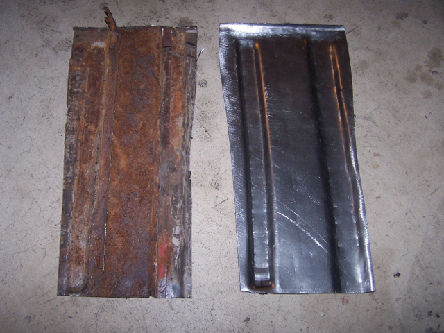
Done. More stitches to Franken914.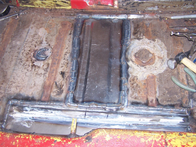
Posted by: FourBlades Mar 31 2012, 10:09 AM
Great work.
Are you a plastic surgeon by any chance? You could make some money in Hollywood...
John
Posted by: Spoke Apr 3 2012, 03:06 PM
Making the driver side crossbrace. Used a 2x3 with an extra piece for the right width. An extra piece makes the bump-out for the parking brake switch.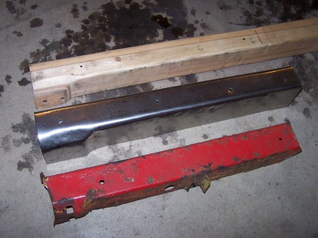
All trimmed up and ready for welding.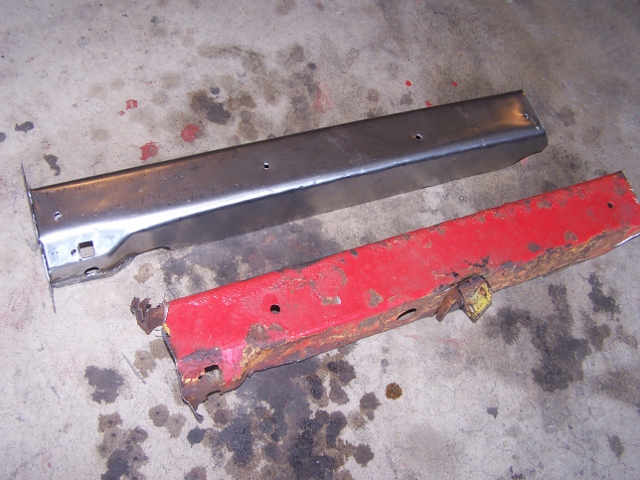
Done.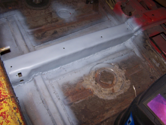
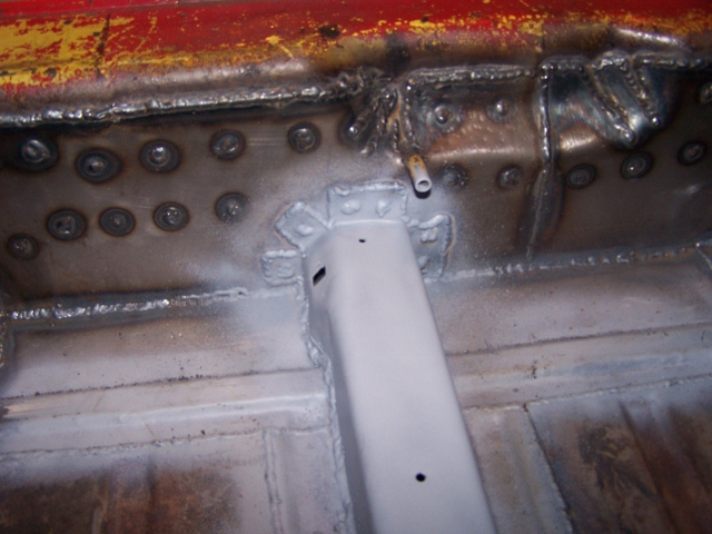
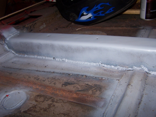
Posted by: trojanhorsepower Apr 3 2012, 06:23 PM
Great work!
Posted by: Spoke Apr 4 2012, 07:54 PM
Little patch on the footwell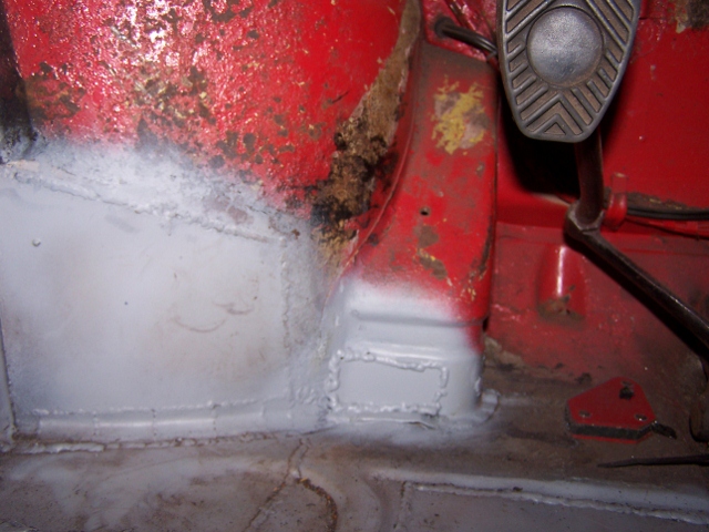
Patch on the inner firewall. This mess will be covered by Engmen's inner long kit.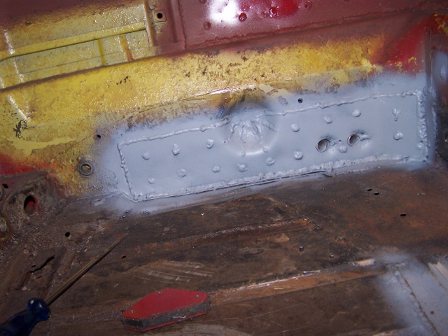
Posted by: Spoke Apr 8 2012, 07:16 PM
The back of the floor was pretty much a mess so I replaced the last 2 channels with a new piece. Also completed the brace parallel to the long.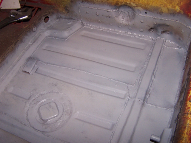
The original handbrake mount was really rusty so I cut off the post and bolt and made a new piece. This is 14ga steel like the original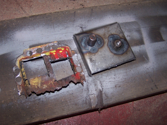
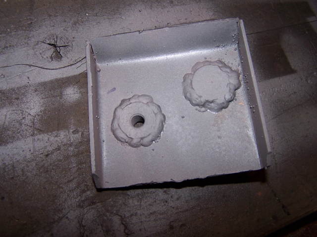
New handbrake mount welded in.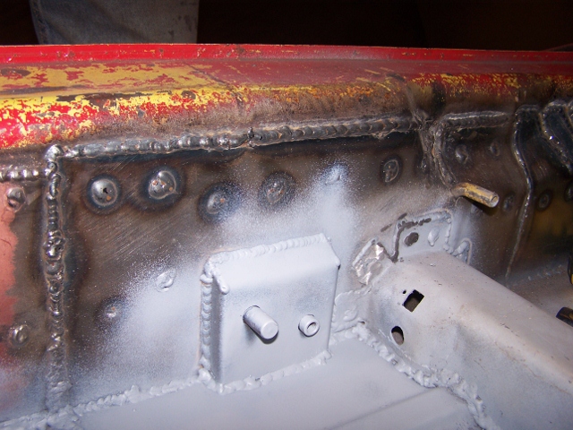
Posted by: uncle smokey Apr 8 2012, 08:18 PM
That is some nice work.
Posted by: Spoke Apr 9 2012, 09:47 AM
Installed the driver seat mounts. Welded some nuts on the underside of the mounts so I can bolt on the hinges.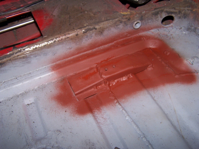
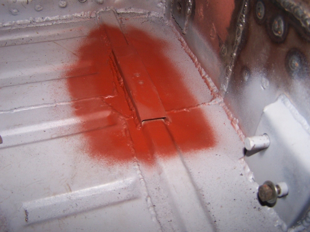
For now, I'm using the same hinges that the PO used to support the seat. Welded 2 bolts onto the part attached to the seat runner and 2 bolts will attach the hinges to the mounts.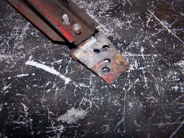
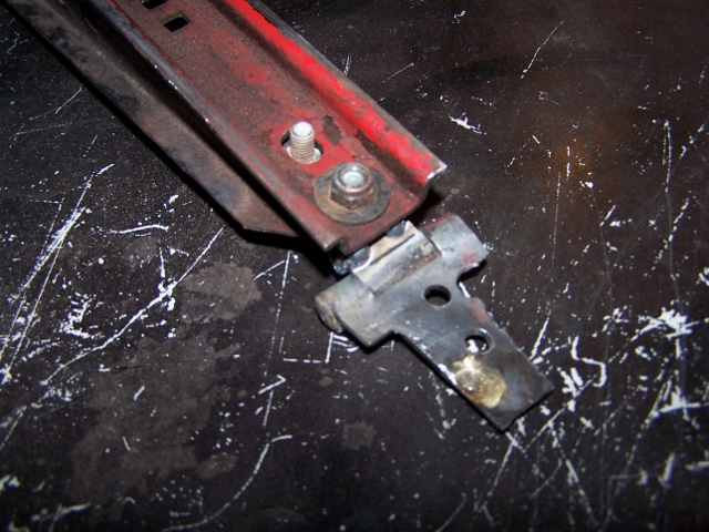
Posted by: Spoke Apr 14 2012, 09:06 AM
Got the seat adjust bracket remounted.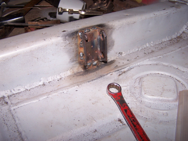
So I cut the hole for the e-brake warning light before mounting the crossbrace and survey says I missed the correct position.
I cut a new hole with my Dremel and welded the scab piece back in the original hole location. 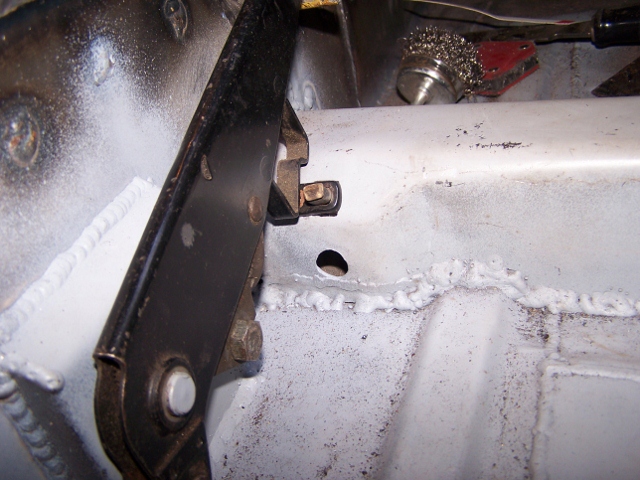
Posted by: Spoke Apr 14 2012, 09:15 AM
Finished welding in my Engman's inner long kit on the back and the driver's side. Took my time welding so as to not twist the chassis.
I'm now finished with the interior de-rusting so I rattle canned the floor and firewall.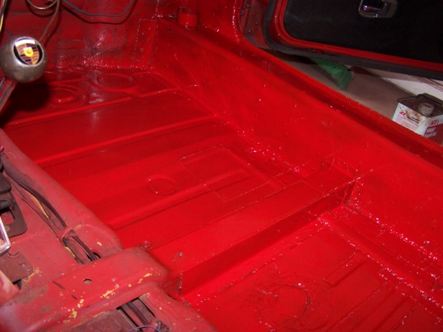
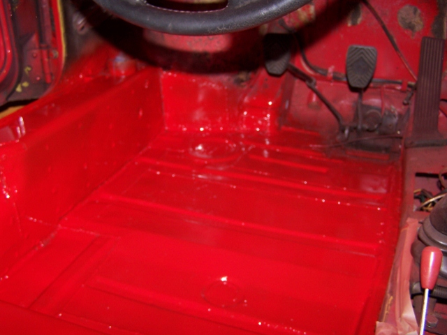
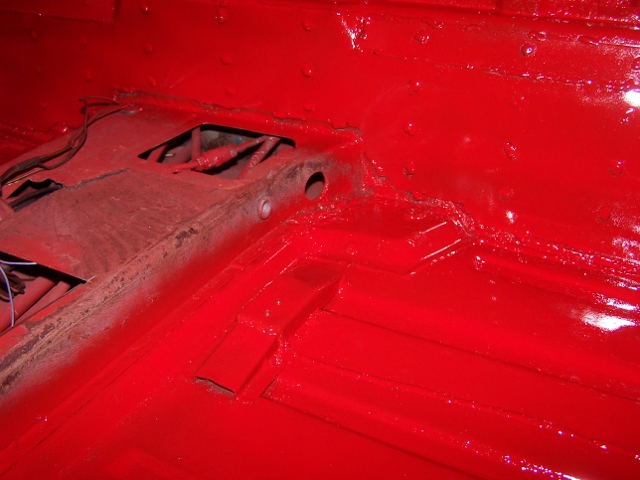
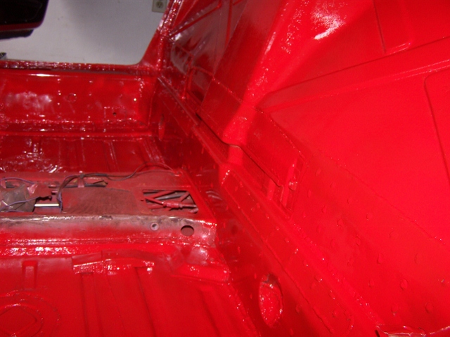
I never liked the little channel for the e-brake cable to transition through so I will try a different method to get the cable to turn. I welded a bolt onto a piece of 14ga steel then to floor and I will put a nylon wheel to allow the cable to move back and forth.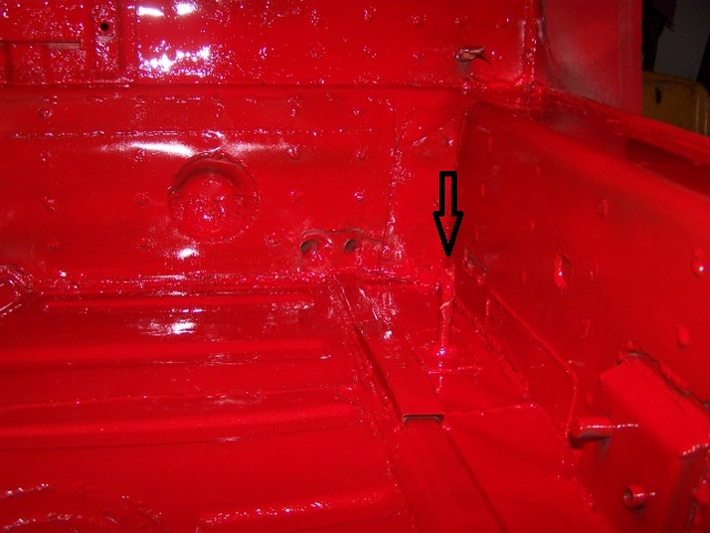
Posted by: Spoke Apr 16 2012, 07:12 PM
When I cut the tunnel open to repair the clutch tube, I decided not to weld the holes shut so I made panels and attached by speed screws. I used the pieces I cut out to help center the panels.
Attached image(s)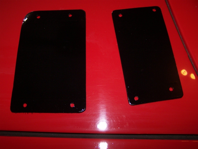
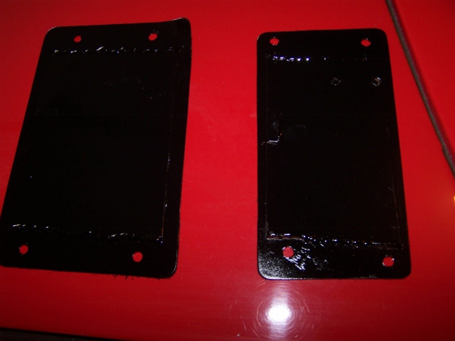
Posted by: Spoke Apr 16 2012, 07:20 PM
Here's my solution to getting rid of the ebrake channel to turn the cable towards the firewall interface.
The bolt is welded to a 14ga plate then to the floor. The roller is free to turn on the sleeve. Works very well with virtually no deflection when the ebrake is pulled to its max.
Attached image(s)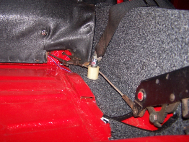
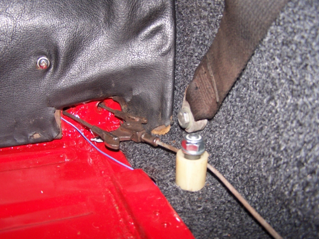
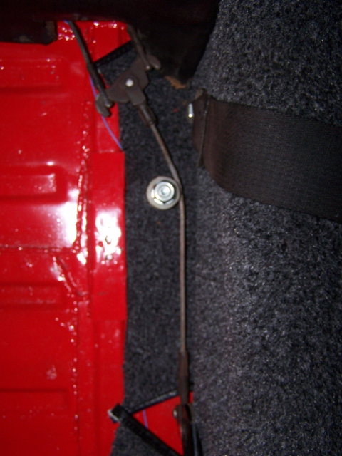
Posted by: Spoke Apr 16 2012, 08:18 PM
Installed the new carpet kit and put the interior back together.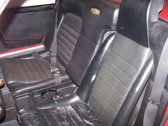
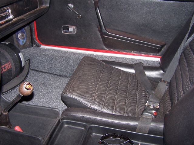
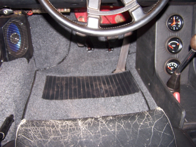
Posted by: jls914 Aug 23 2012, 07:00 PM
Spoke,
Came across your posting while searching for fuel pump relocation info. Very nice indeed!! You sure put alot of time and love into this 914. Can you tell me what fuel pump you used and detail the hose connections from bulkhead, tank and pump? I want to update mine as well using a 2 port pump. I would appreciate your input.
Thanks,
Jim
Posted by: Spoke Aug 24 2012, 04:19 AM
Jim,
First off,
You should start a thread about your car, post pics and ask questions there. You will get a wider response from the World that way.
The fuel pump is the later 2 port type.
From the fuel tank large port, run to a filter, then to the pump inlet (larger port).
From the pump outlet, to one of the center tunnel fuel lines to the engine.
Then return back from the engine in the other center tunnel fuel line and into the tank smaller port.
Pretty simple. I'm assuming you have fuel injection and not carburetors.
Posted by: jls914 Aug 24 2012, 06:03 AM
Thanks. Can you tell me where is the best place to buy the pump? Manufacturer, model#, etc. I am moving and once my garage is complete, I'll bring my '73 and start a thread about it. It is stock and has fuel injection. I moved my old pump up front, but my first pump leaked through the check valve and my second pump leaks out of the body. This is why I want to go to a newer, cheaper and readily available pump and dothe complete re-plumbing job. Again, thanks for the info.
Jim
Posted by: Spoke Nov 8 2012, 11:44 AM
Getting ready to convert to 5-lug. Will be doing the work next week while I have a bit of time.
Front end is from a 72 911 with M calipers.
Rear end is using the hub from the 72 911 with vented rotors, widened 914 rear calipers and cut (by Eric Shea) rear 911 rotors.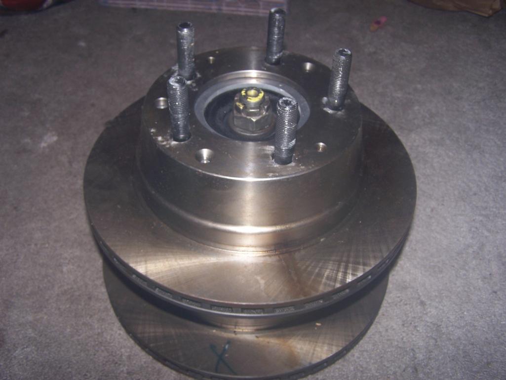
I had to replace the stock studs with the vented rotors so I went with 66mm studs which provide more than adequate threads.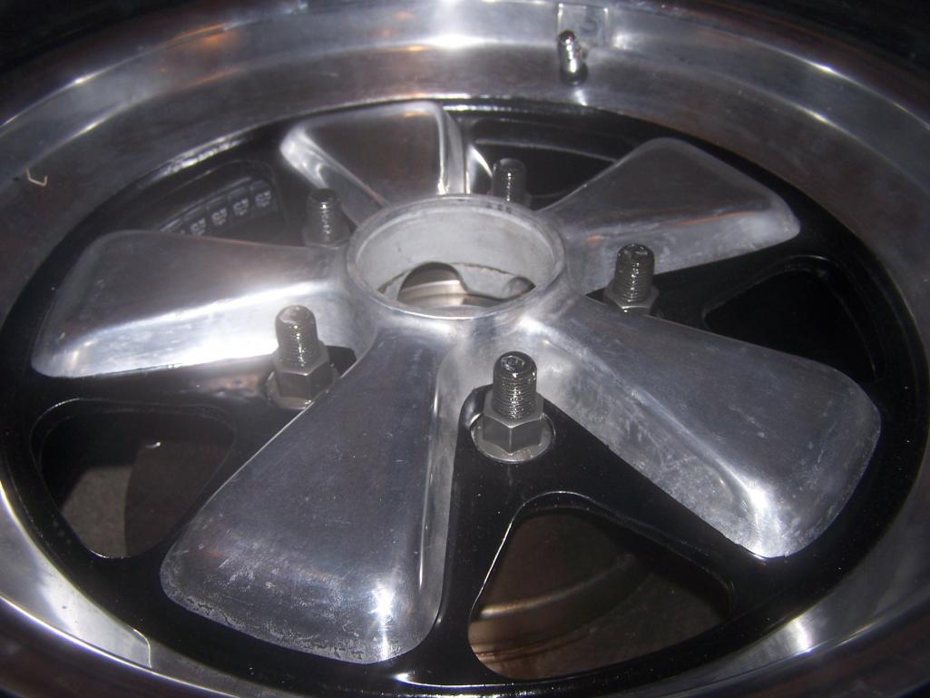
Tires are Riken Raptors; 205/50/16 on 6x16 for the front; 225/50/16 on 7x16 on the rear; and 195/60/14 on 5.5x14 for the spare.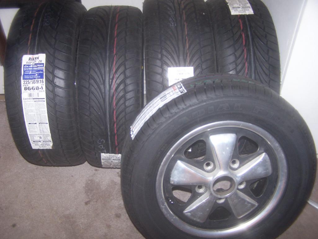
Very nice caliper pad retaining clips from Eric Shea at PMB.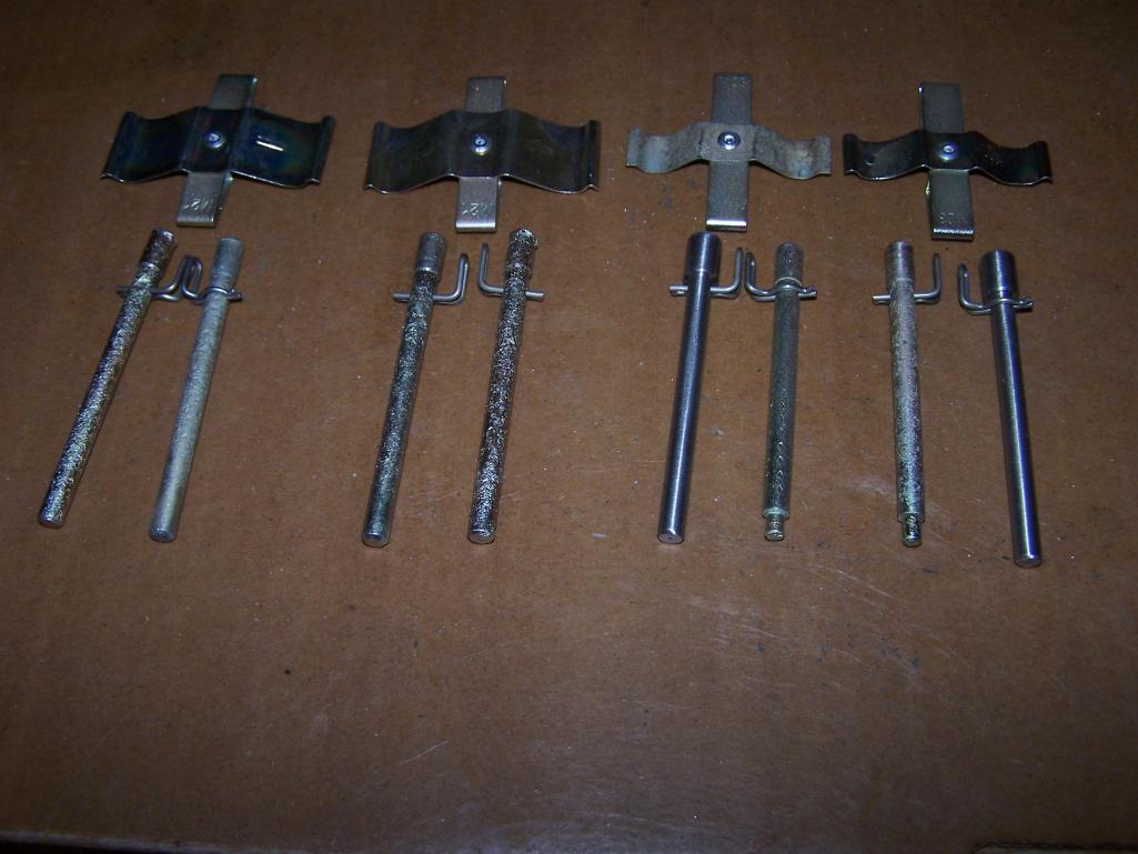
Posted by: Spoke Nov 11 2012, 03:47 PM
The 5-lug process has begun. Doing the front end first.
Started with the drivers front. These replicas will be for sale soon.
It scares the crap out of me to get under or even beside the car with the entire front off the ground. I used 2 jackstands on each side along with the floor jack.
Attached thumbnail(s)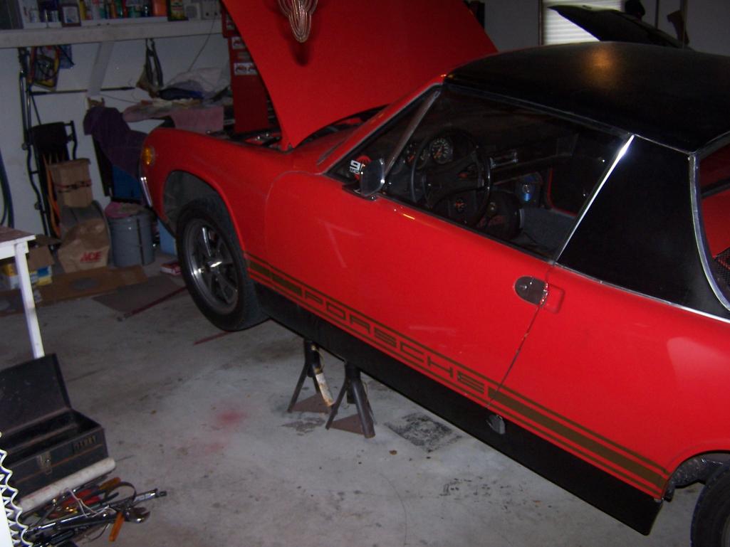
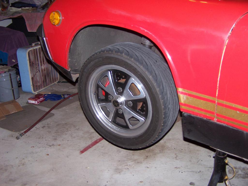
Posted by: Spoke Nov 11 2012, 03:51 PM
Drivers front is done. Got big boy pants on now.
Eric Shea restored calipers are pretty. 
Attached thumbnail(s)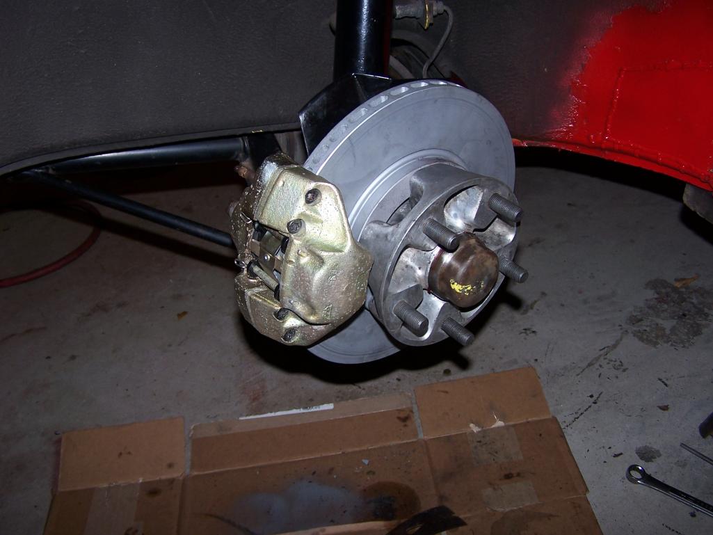
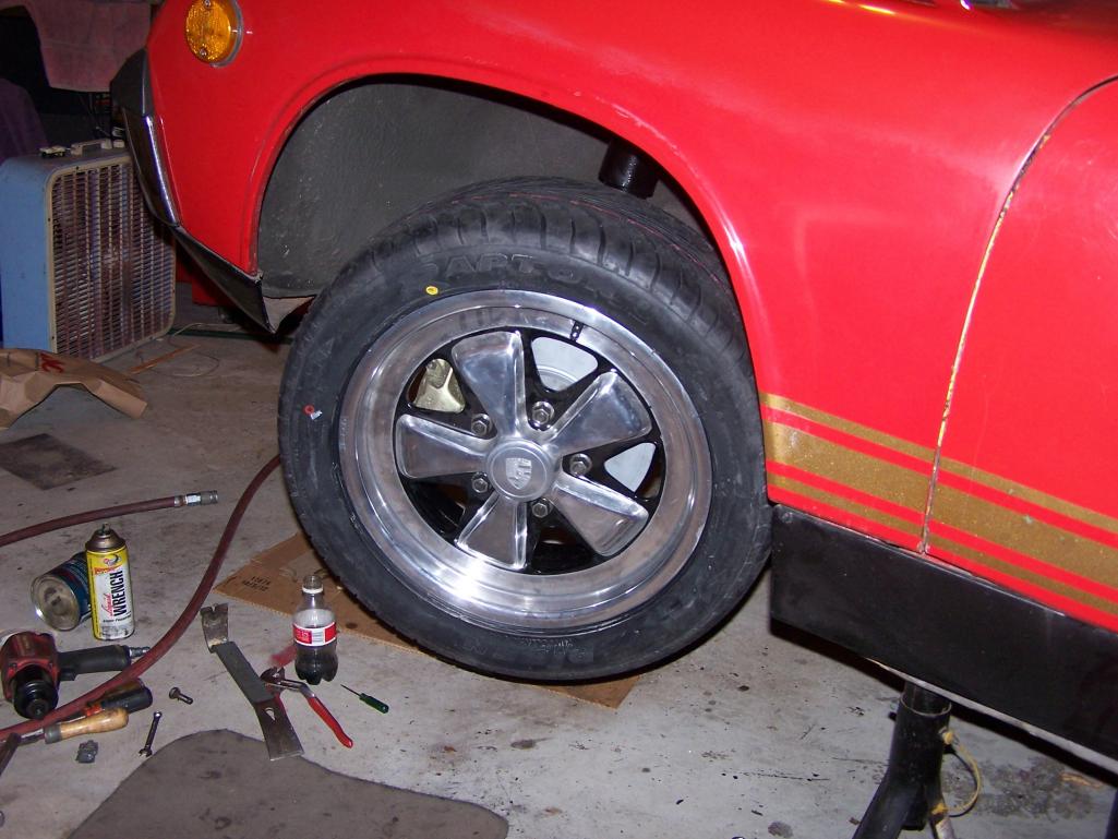
Posted by: Spoke Nov 17 2012, 12:07 PM
Started working on the rear suspension when I had my "oh shit" moment.
After reading all the threads on converting the rear to 5-lug using 911 hubs like I had, I absorbed absolutely none of the facts of what I needed to do to use the 911 hubs.
That is until I removed the half-shafts from the car and compared the 914 hub to the 911 hub. Then it all came crashing down. I needed to get different shafts and trans flanges.
At that point I decided to go with drilled 914 hubs and use screw-in inserts and sell the 911 hubs/spline/CVs (they are sold).
Eric Shea provided some beautifully drilled and tapped hubs.
I'm using these 65mm race studs from:
http://www.race-studs.com/servlet/the-17/M14x1.5-ACS-Race-Stud/Detail
Attached thumbnail(s)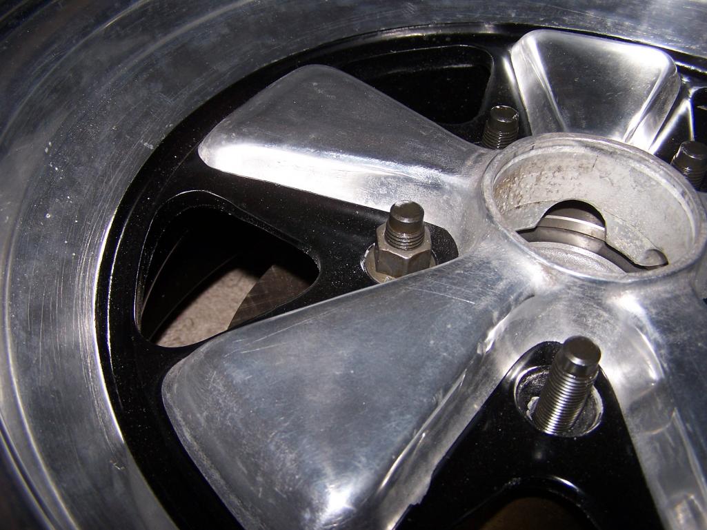
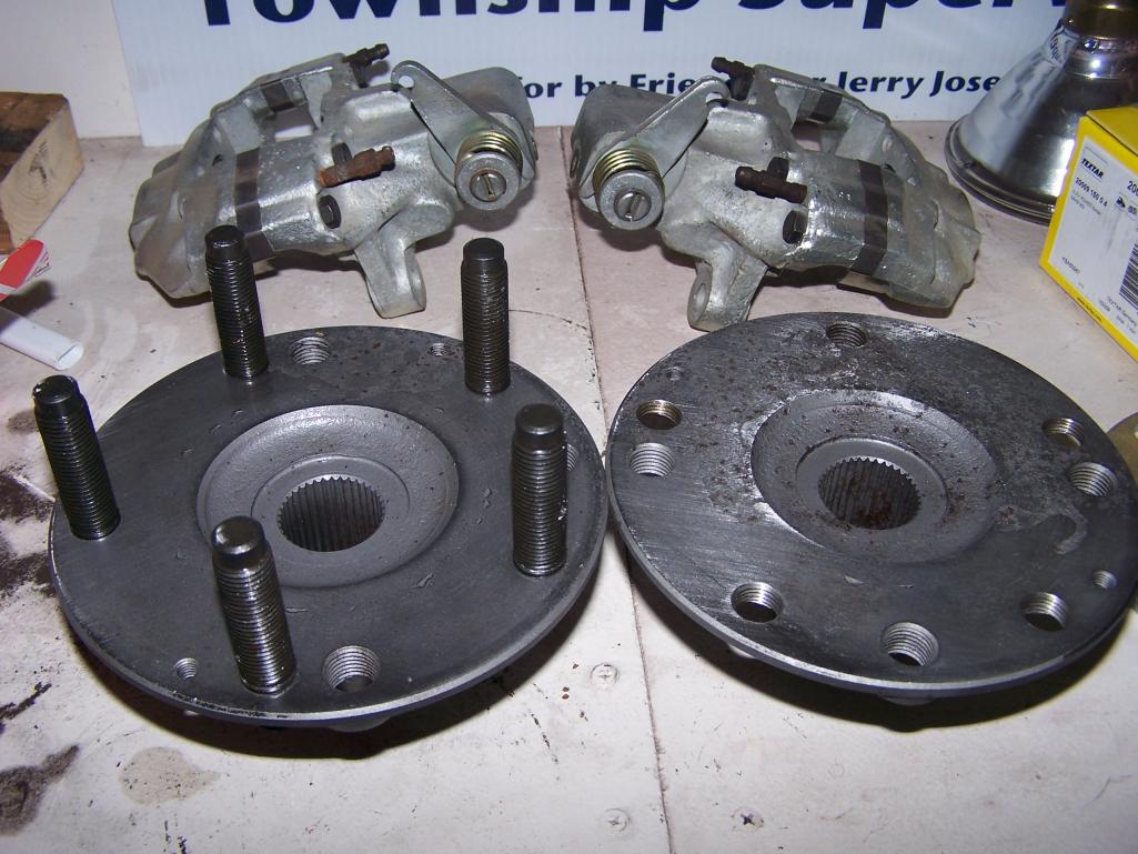
Posted by: sixnotfour Nov 17 2012, 12:41 PM
wow, perfect timing or JIT.
Posted by: Spoke Nov 17 2012, 08:23 PM
Put the rear swing arms back together.
Freeze the bearings in the freezer and heated the arm with a heat gun on low. The bearings dropped right in without outside force.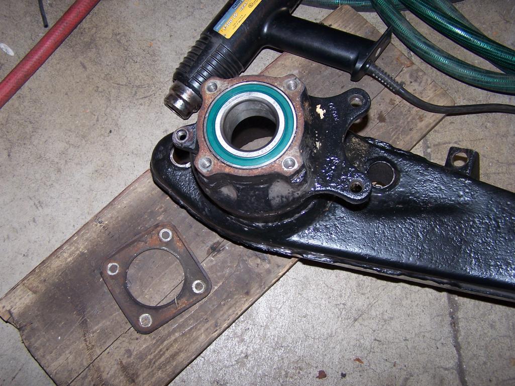
Freeze the hubs in the freezer and heated the arm & bearings with a heat gun on low. Ratcheted the hubs right in with very little force.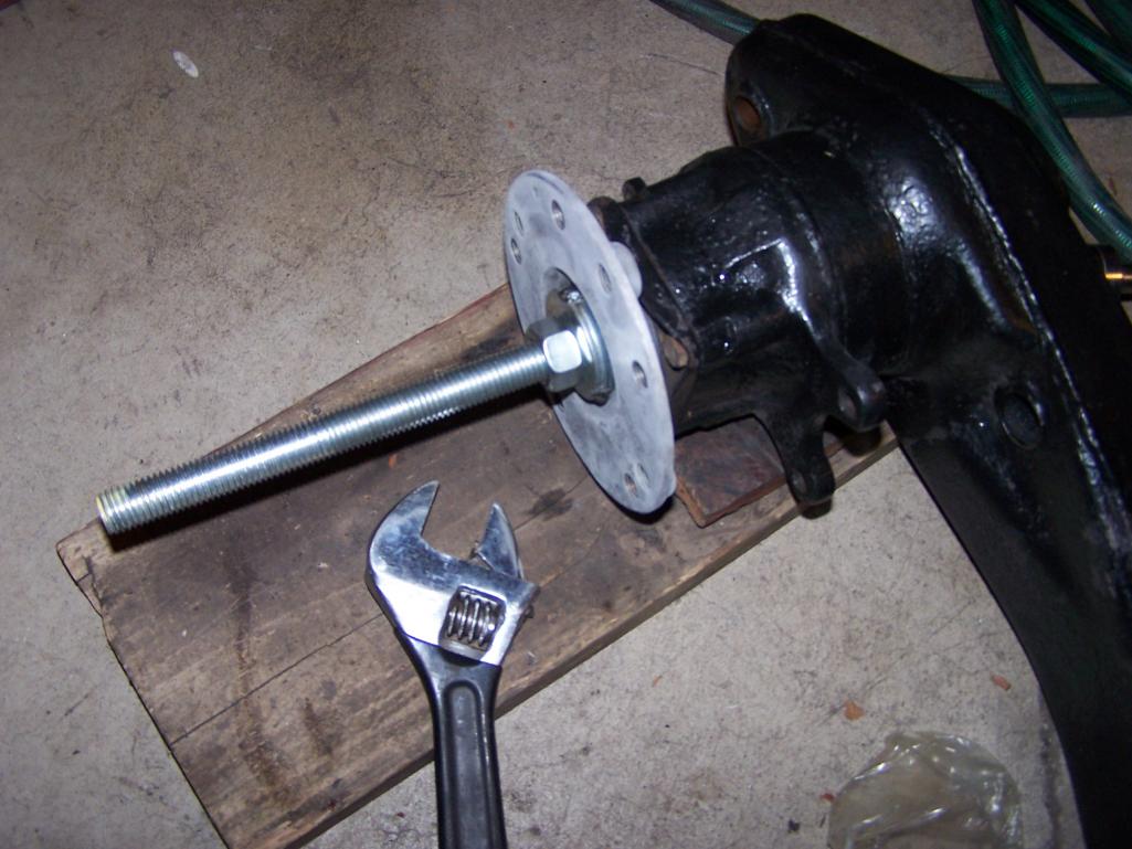
Posted by: Spoke Nov 18 2012, 10:36 AM
While I'm in there:
Always had a bit of a backfire as well as cylinder noise on the drivers side proportional to the throttle position. Figured it some exhaust leak.
Here's the culprit: broken weld on #1 exhaust tube. The opposite bolt was loose as well.
Attached thumbnail(s)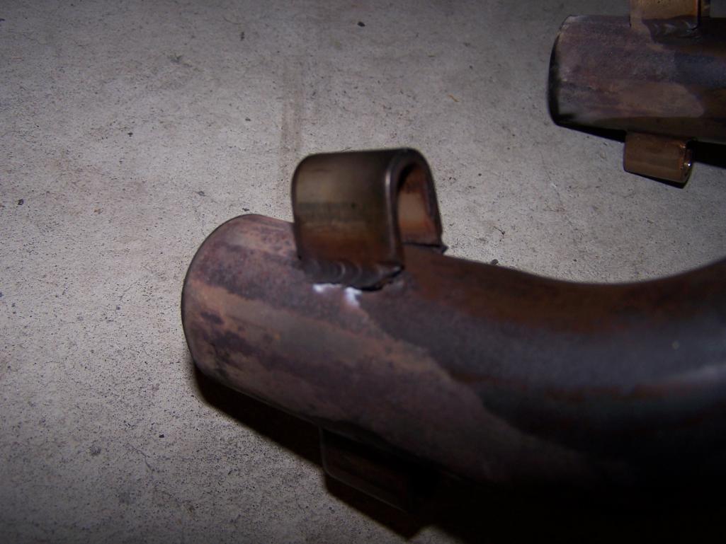
Posted by: Spoke Nov 21 2012, 05:59 PM
These pics are the same as in my other thread about vented rear rotors.
This first fitment with the rock shield bracket under the caliper mount shows the caliper not centered on the rotor.
According to Eric Shea, the rock shield is required for road use but the bracket cannot be under the caliper mount.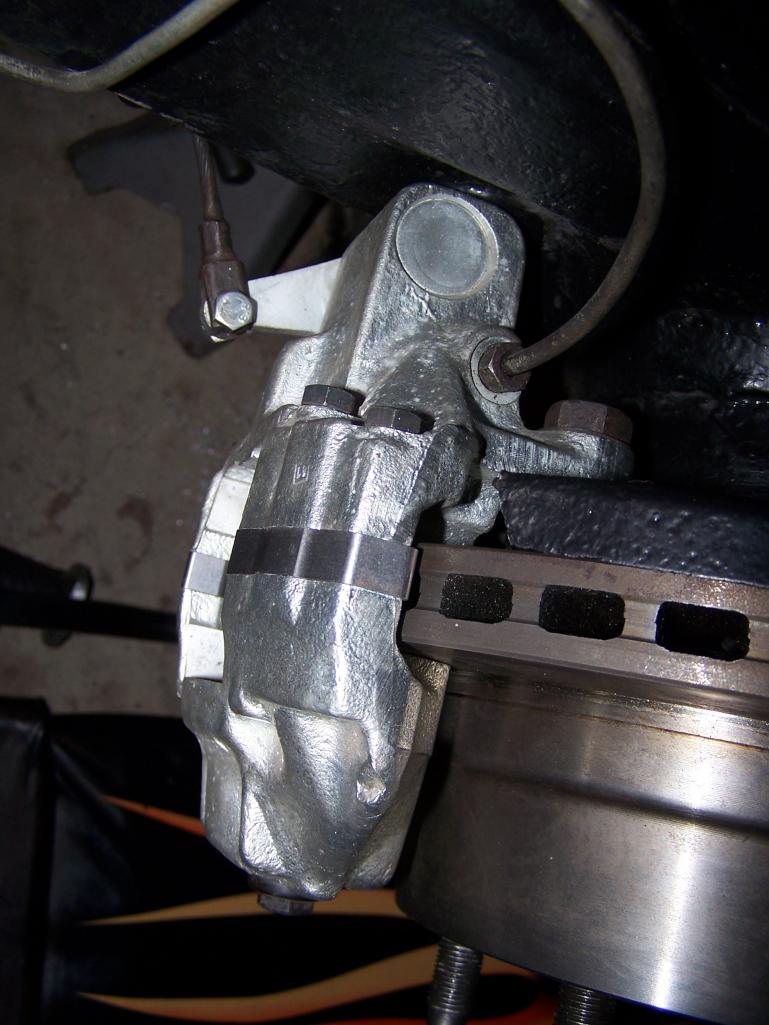
Here's the proper fitment with the caliper mount fastened to the swing arm ear.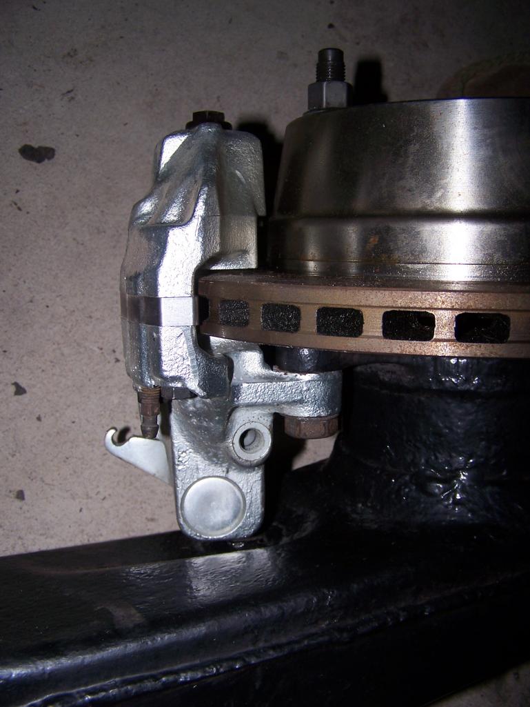
I still needed the rock shield so I modified the bracket to go on the top of the caliper mount.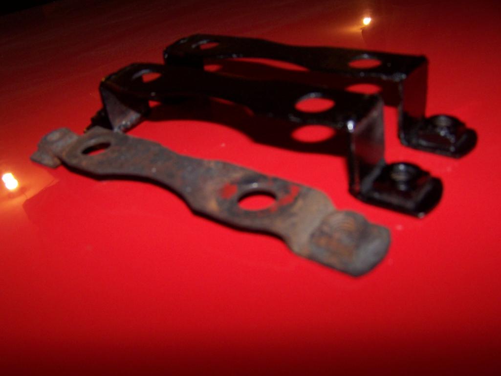
To mount the rock shield on top of the caliper mount, a little of the caliper webbing needs to be filed.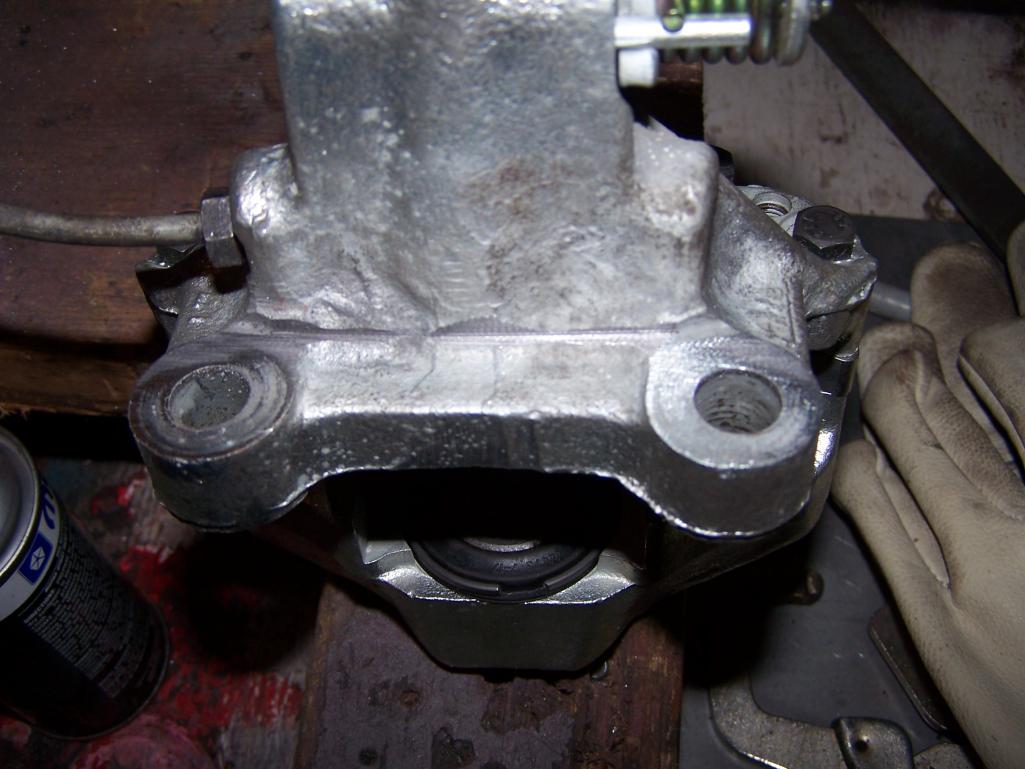
Posted by: Spoke Nov 21 2012, 06:05 PM
Here is the modified rock shield bracket ready for the caliper. 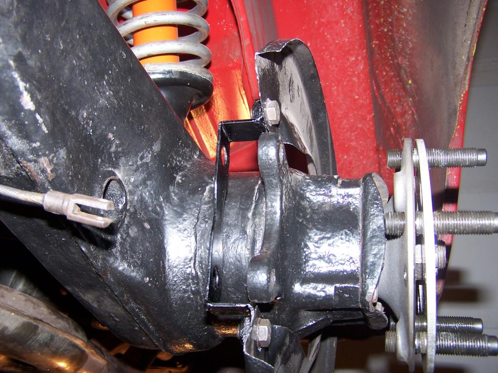
With the rock shield bracket on top of the caliper mount, the caliper is properly spaced about the rotor.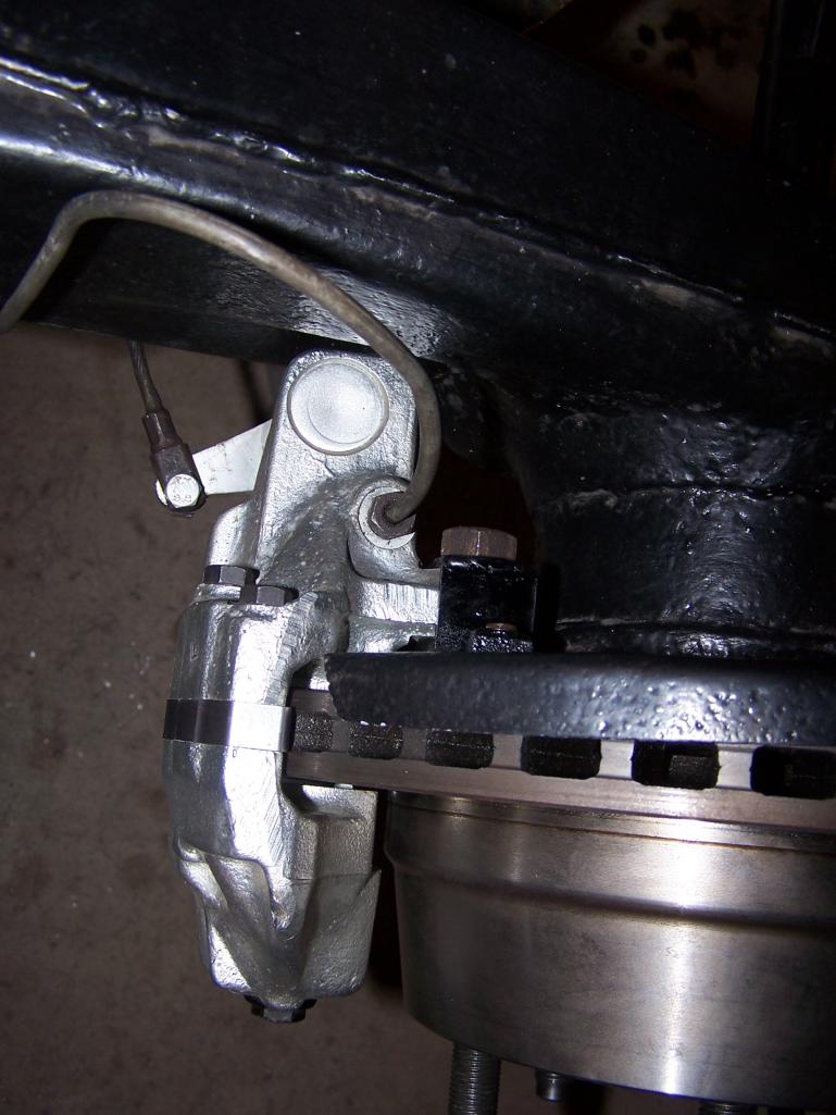
Posted by: Spoke Nov 21 2012, 06:10 PM
Had to pull the fenders out on each side. Have just a bit of room. I'll need to roll the fenders a little more then smooth out the wrinkles.
Love the big boy wheels and tires on the back.
Attached thumbnail(s)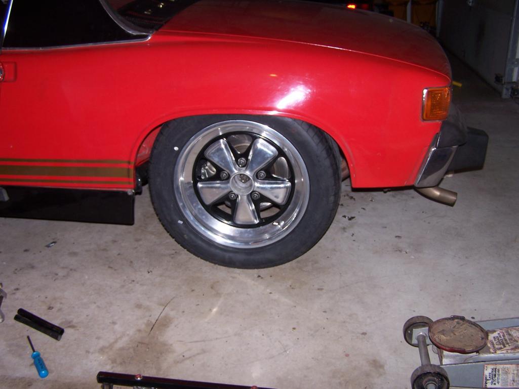
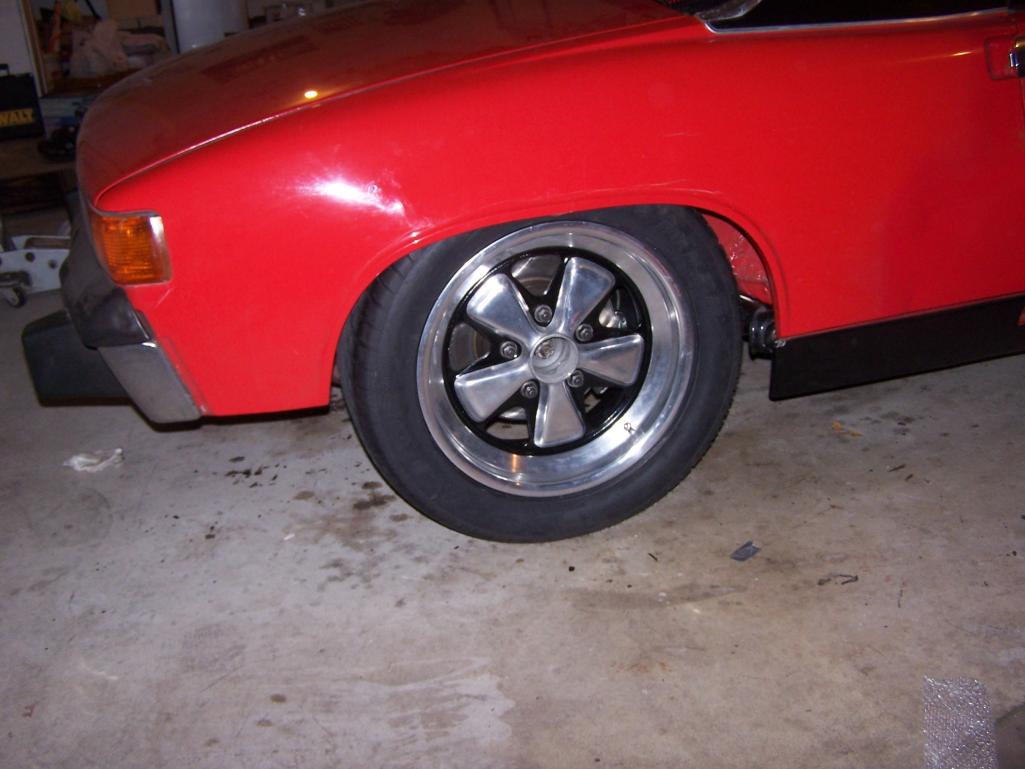
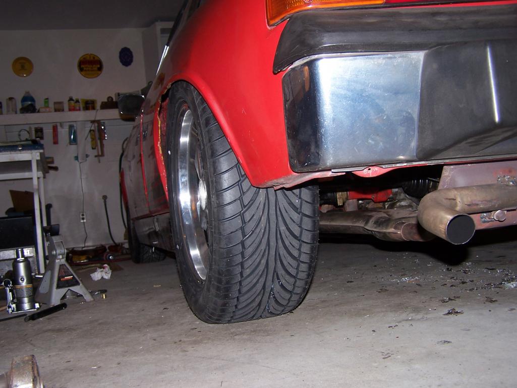
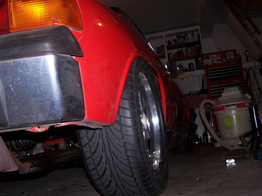
Posted by: Chi Town Feb 3 2013, 06:18 PM
I just read your entire thread...Amazing work!!
Posted by: Spoke Sep 1 2013, 07:44 PM
Time to debounce the tachometer. I'm tired of seeing the tach needle bounce all over the place when I shift gears or rev the engine.
The 914 tach is underdamped meaning the tachometer will respond quickly to changes in RPM but will oscillate after the change and settle to the correct RPM.
Something like the red line below is desired. The tach will respond a bit lower to quick jabs of the throttle but should not bounce or oscillate upon every RPM change.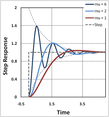
Here's a quick video of the tach without damping.
http://www.youtube.com/watch?v=VCgLzBJxoEM
An easy way to damp is to add a capacitor directly across the winding of the needle armature. I've found that early tachs have a more complicated circuit and simply adding a cap across the armature not only settles the needle but causes the needle to read about 1.5x the actual RPM.
So I purchased a 74+ tach and added a 2200uF capacitor across the armature. The cap was just hot-melt glued into place and 2 wires soldered to the circuit board of the tach.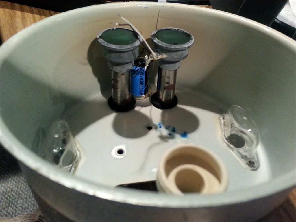
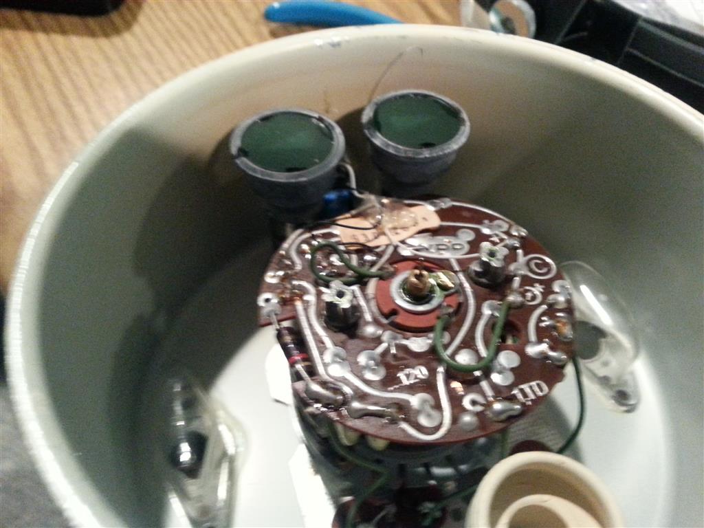
Here's a video of the tach with the 2200uF cap installed. The tach is much more damped and doesn't wildly overshoot like before.
http://www.youtube.com/watch?v=VFTXRVlUuyg
Posted by: timothy_nd28 Sep 1 2013, 08:22 PM
Been there and tried that, but was never happy with the results. Air core motors are the way to go IMHO
Posted by: Spoke Aug 14 2014, 10:55 PM
Time to add a 3rd brake light to the 914. Don't want a repeat of the rear-ender as documented in the first post of this thread.
I purchased a 12 inch strip from Summit Racing and decided to mount it below the targa trim strip.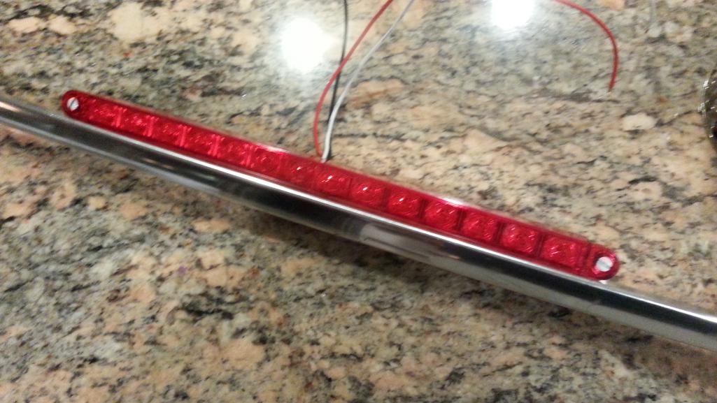
This is how it will look. I read all the other 3rd brake light threads and one previous 3rd brake light adopter mentioned that a low profile brake light below the targa trim would not interfere with the rear view mirror vision. So this is how I will mount the light.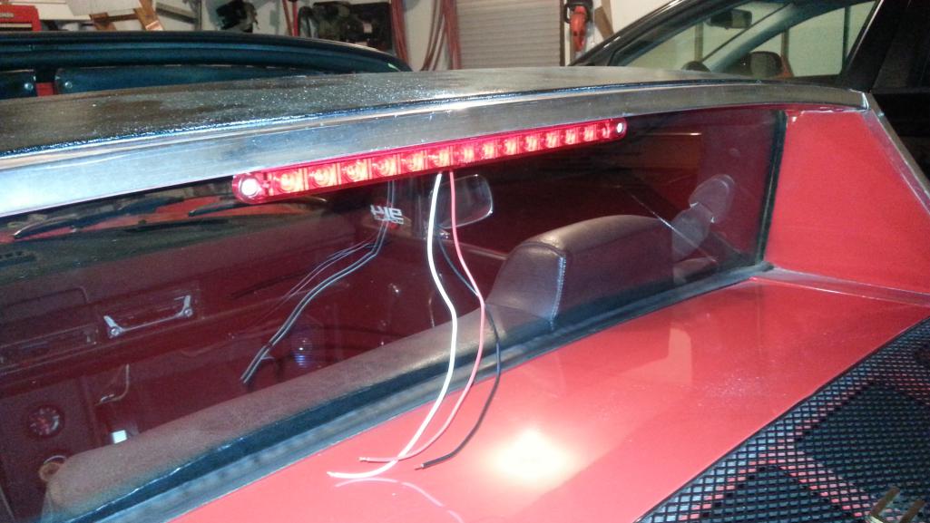
I wanted a secure mounting so I used a small 90 degree angle clip I had laying around. I trimmed off a bit of the targa trim so the clip will mount flush on the trim.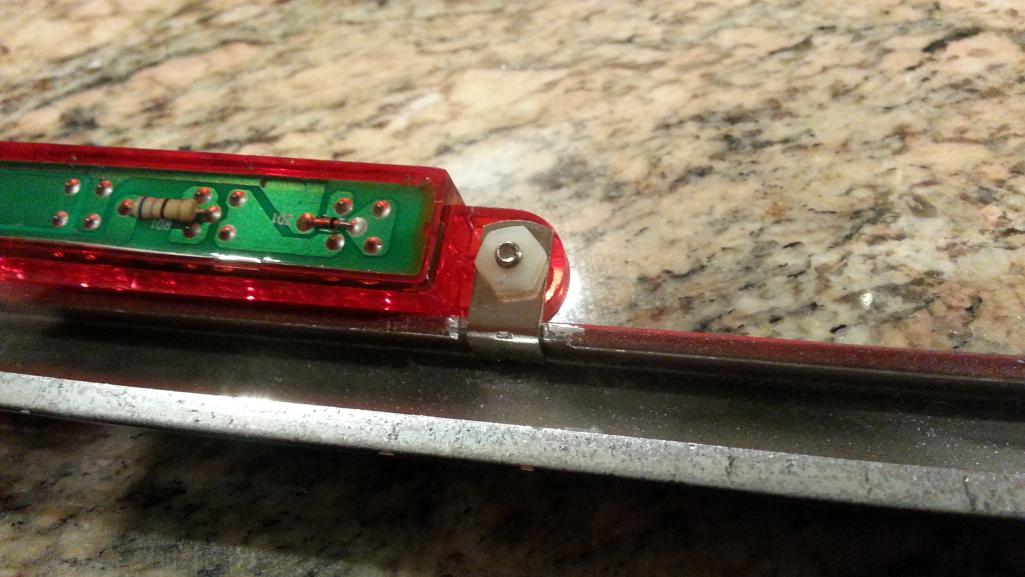
Here's how the light will mount. Excuse the nylon nut. It's 1am in PA and nothing is open at this time. BTW, the screw is from an AC socket wall plate. I'll get some nice hardware for the final mounting.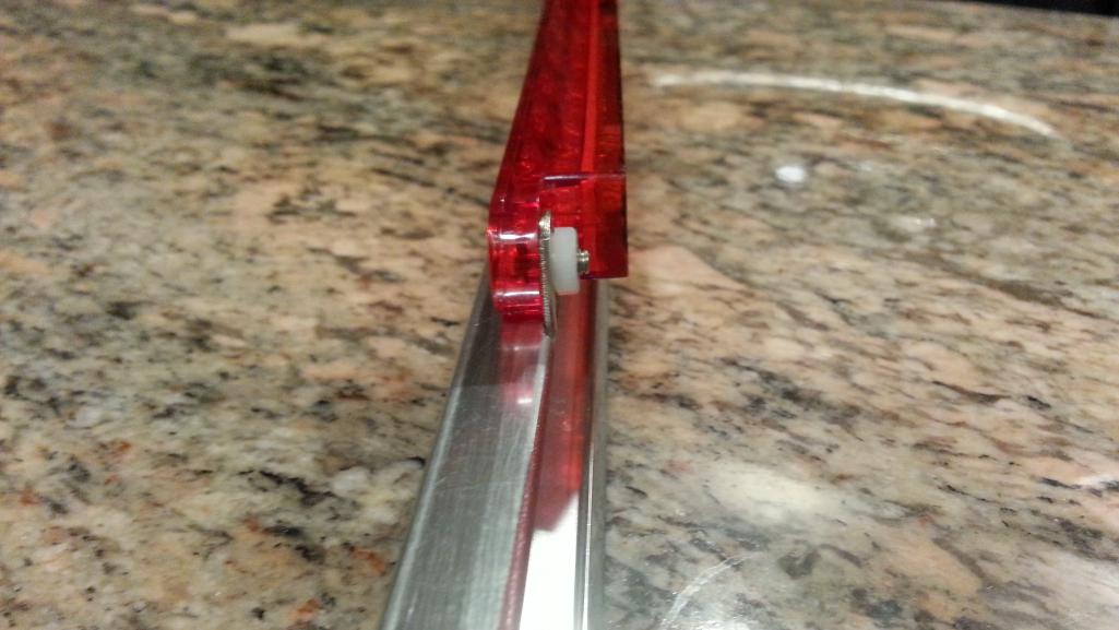
Posted by: Spoke Aug 17 2014, 12:04 PM
Used blue painters tape to hold the wires out of the way of the roll hoop seam.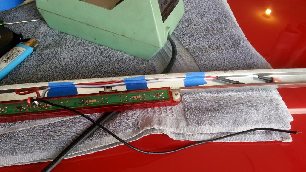
Had to file a channel in the roll hoop seam for the wires to pass through. Again tape is used to buffer the wires.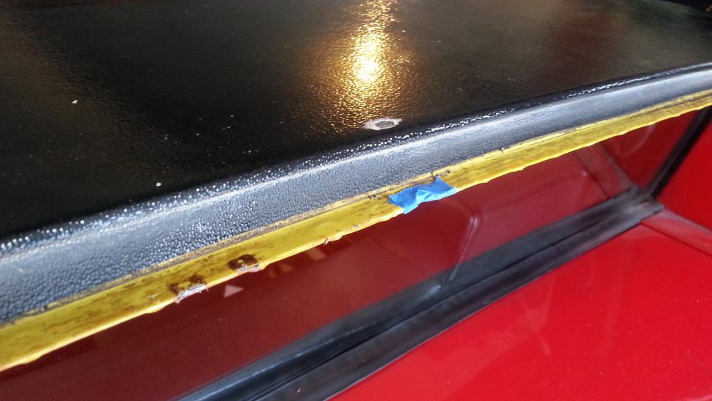
Posted by: Spoke Aug 17 2014, 12:14 PM
Connected to the brake circuit at the driver side brake housing. Used a 1-to-2 spade to make an easy connection.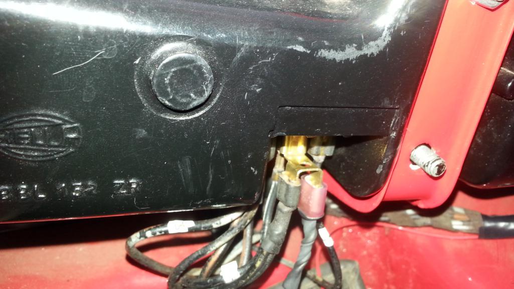
Taped the extra wire to the wire bundle about every 3 inches to keep it neat.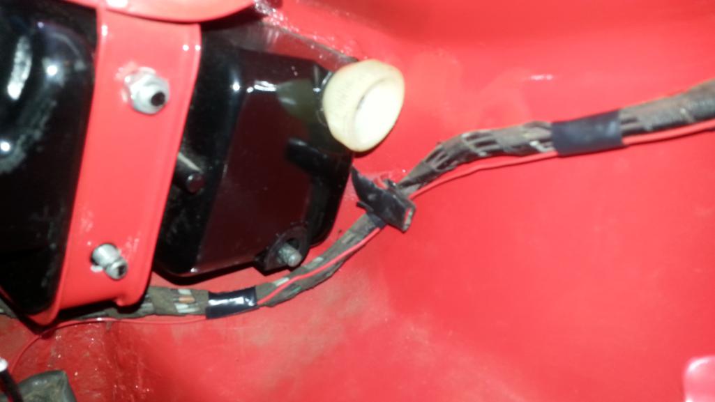
Used a home made lug to attach LED ground to the chassis.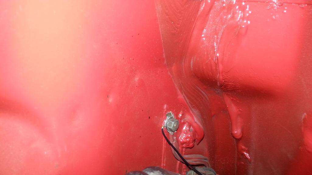
Twisted the wires together to go up under the side grill.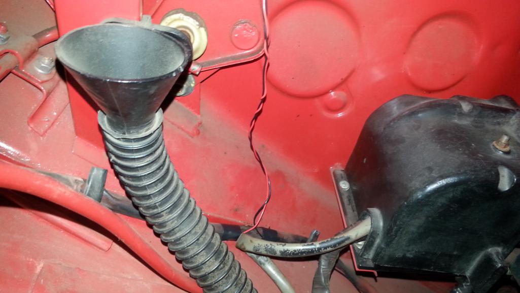
Taped the wires to the roll hoop. These will be under the trim piece.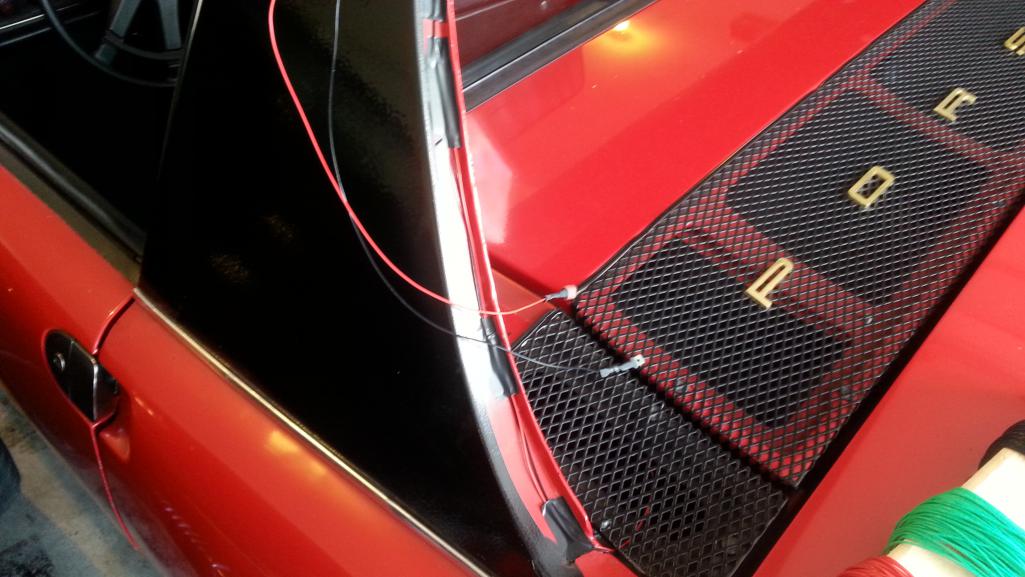
Posted by: Spoke Aug 17 2014, 12:21 PM
BTW, I'm using United Pacific 38949B - United Pacific LED Taillight Bar available at Summit Racing. They come in 6, 9, and 12 inch lengths. This is the 12 inch model.
The light bar wires are attached using spades so I can disconnect easily if needed.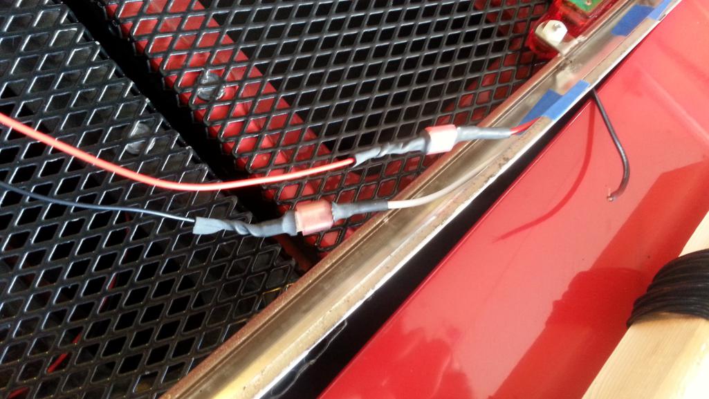
The lightbar tucks in real nice under the roll trim.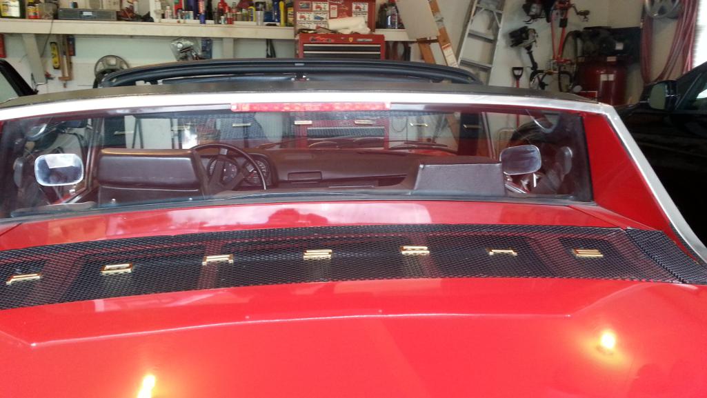
The 3rd brake lights are quite bright and should help those behind to see me better. 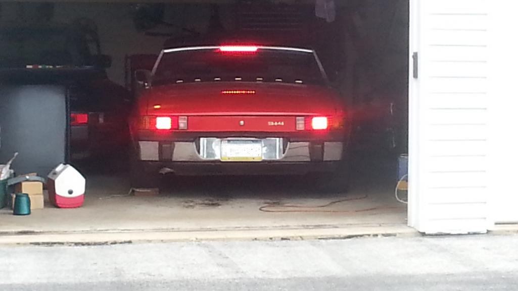
Posted by: Rleog Aug 17 2014, 02:20 PM
Thanks for taking the time to post these step by step illustrations. Nicely done.
Posted by: Spoke Jun 2 2015, 06:23 PM
Finally got around to cleaning up and mounting the bumper I picked up at Hershey this year. The new one is the one with the license plate frame.
The old one was a POS bumper I picked up off of eBay for $10 after the accident. The main problem with the old bumper was someone tried to mount a hitch or something on the bumper and put 6 to 8 holes on each side. That's why the front bumperettes were put on the rear bumper.
Attached thumbnail(s)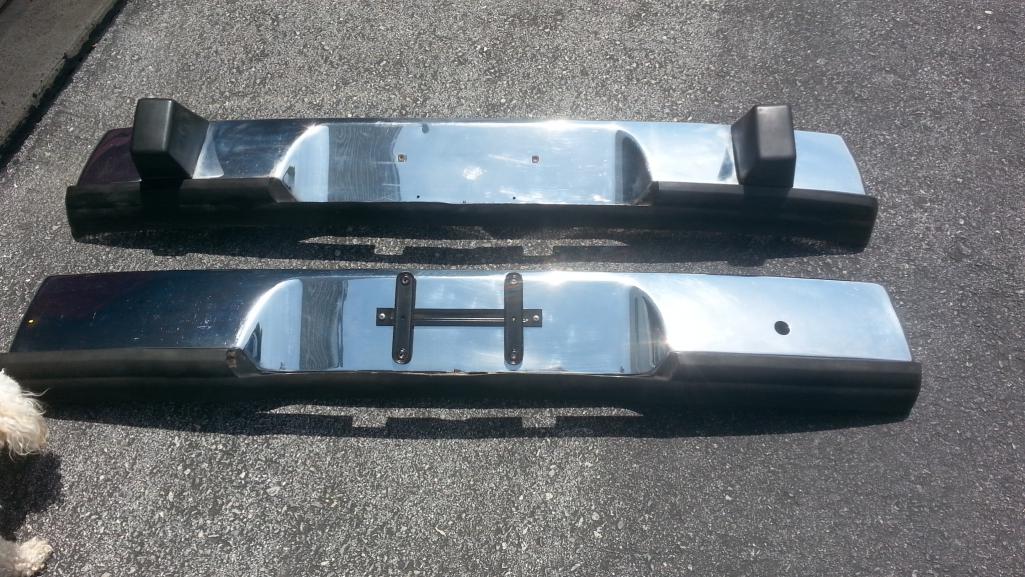
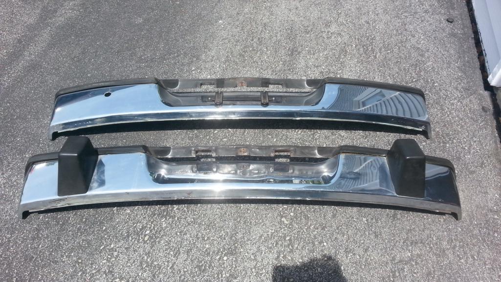
Posted by: Spoke Jun 2 2015, 06:27 PM
Cleaned up the rear end before installing the new bumper. Need to find a nice tow hole cover now.
Attached thumbnail(s)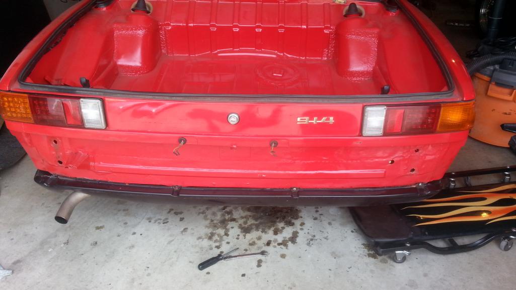
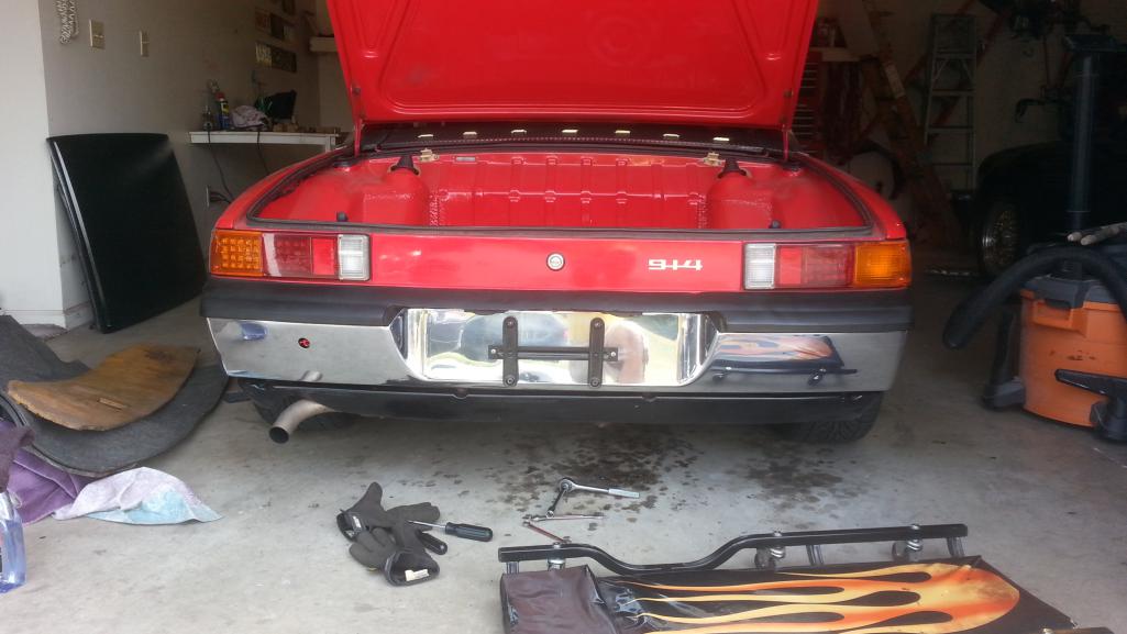
Posted by: Spoke Jun 2 2015, 06:31 PM
Mounted an LED turnsignal on the passenger side. I made this PCB over a year ago and never assembled it. This one uses surface mount LEDs and discrete lenses. They're a real pain in the ass to install and very expensive (about $2 per LED + 1$ per lens) but they can be very bright.
Now the passenger side matches the driver side.
Attached thumbnail(s)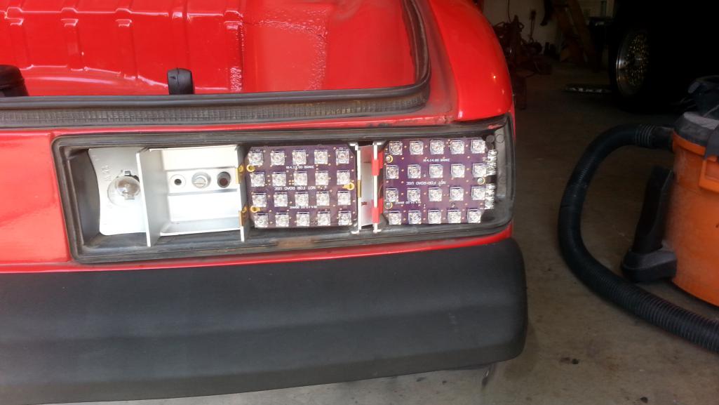
Posted by: Spoke Oct 3 2015, 06:12 AM
Swapping engines now. Removing the 1.8L with FI and installing a 2056 with dual carbs.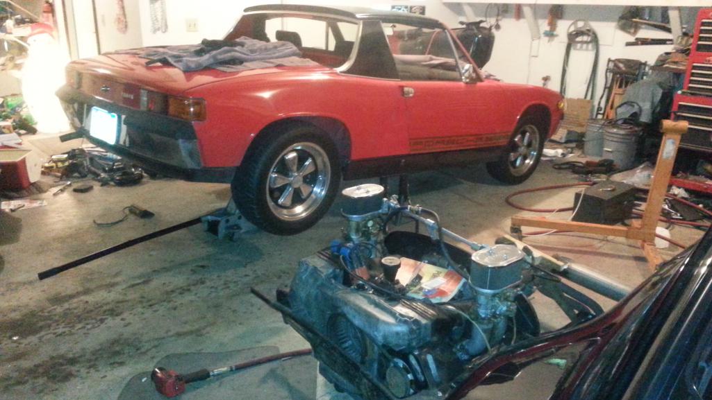
Prepping the engine for removal.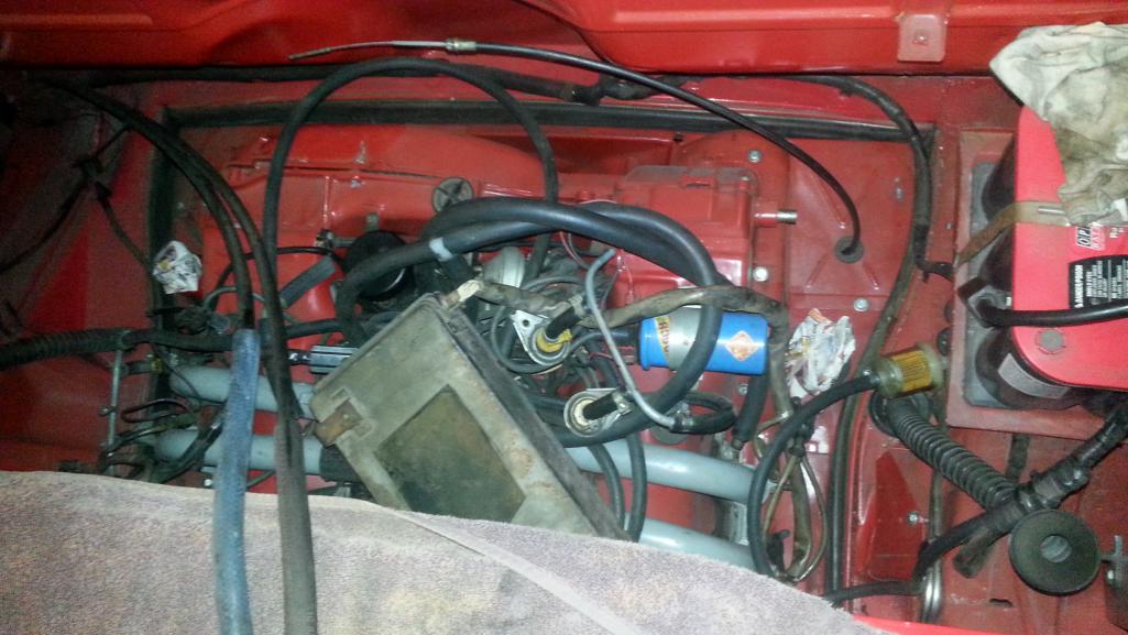
The carb fuel pump has a pre-pump filter. I'll also use a post pump filter. The return line will be plugged at the engine.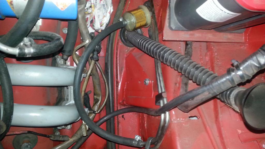
Removed the hood in preparation to change the fuel pump to low pressure.
Posted by: Spoke Oct 3 2015, 06:17 AM
Tank is lifted to provide access to the fuel pump.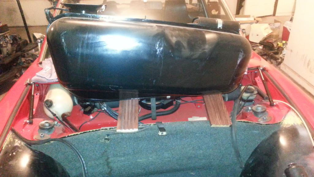
I made the fuel lines under the tank long enough to be able to lift the tank out without having to disconnect the lines from underneath the car.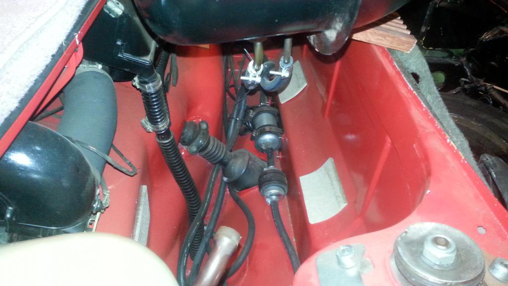
I finally located the origins of a minute gas smell. The nipple was leaking ever so slightly. The gas was only noticeable when the car sat for long periods of time.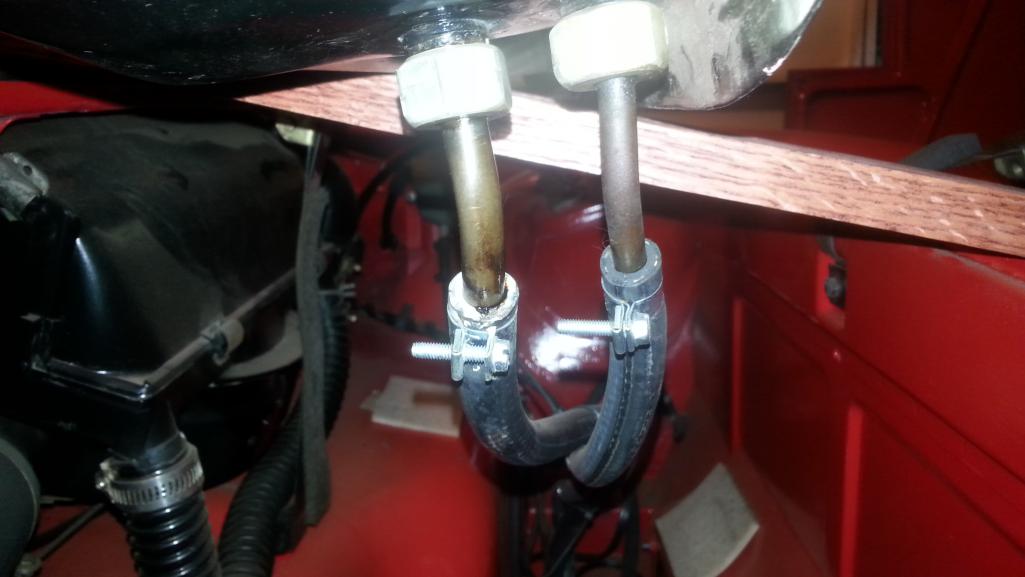
Out with the old and in with the new.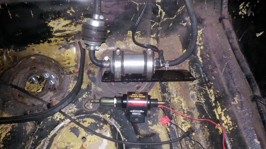
Posted by: effutuo101 Oct 4 2015, 12:05 AM
Keep it up! Looking good.
Posted by: Spoke Oct 4 2015, 05:17 AM
Engine is out.
Next up:
1) Remove transmission and install on new engine.
2) Remove engine bar and install on new engine.
3) Install new engine.
Attached thumbnail(s)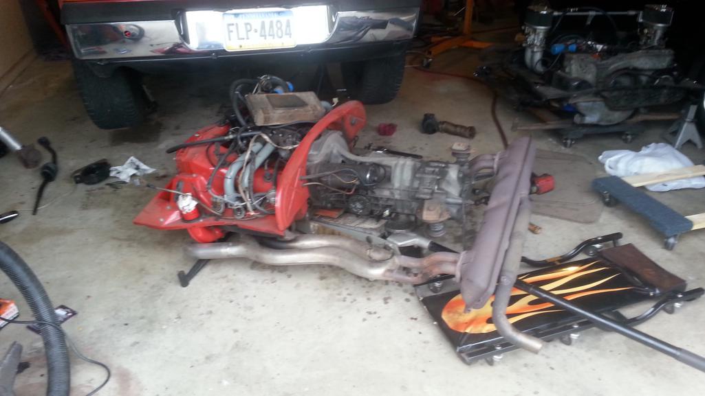
Posted by: Spoke Oct 12 2015, 09:57 AM
The 2056 engine is in the car and running.
This engine has plenty of grunt. I can now feel acceleration in all gears. Totally transforms the car. On local twisties where I used to accelerate all the way from one corner to the next with the 1.8L, I now find myself coasting most of the way since I'm quickly up to the max speed I'm comfortable with.
Had the carb linkage towards the rear of the engine but it hit the rear firewall. Also got the carbs working pretty well. A little stumble coming off of idle but runs real good with the throttle open.
I used the clutch which came with the engine. It was a bit worn but still serviceable. It chatters a lot in 1st gear but is ok to take off in 2nd. I'll need a new clutch, PP, TO bearing, and pivot bushing.
Attached thumbnail(s)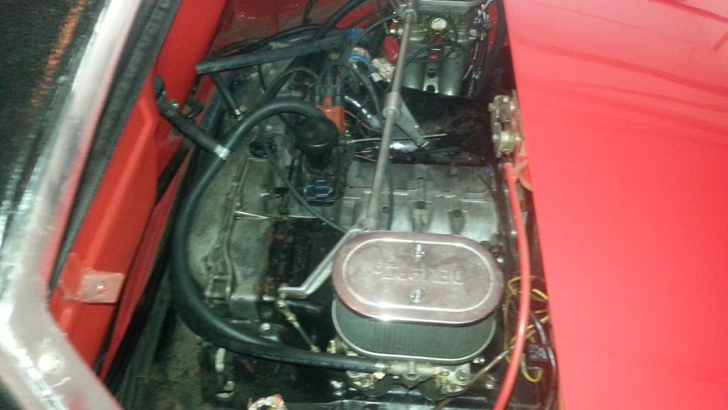
Posted by: Hoppie944s2 Oct 12 2015, 10:07 AM
Interested in selling the rear bumper you are not using?
Posted by: Spoke Oct 12 2015, 10:58 AM
Interested in selling the rear bumper you are not using?
You can have it for free if you want. You have to pick it up though. The bumperettes are on there to cover up about 6-8 holes on each side where a PO mounted a hitch.
Posted by: Hoppie944s2 Oct 12 2015, 11:40 AM
Ill take it! will send you a PM.
Rob
Posted by: cgnj Dec 19 2023, 10:20 PM
I made a center console (actually this is the 2nd one) from wood using the original as a starting template.
The sides are high enough that they wedge in between the floor and the dash and thus do not need any securing straps.
I made the opening for the shifter to use the original shifter boot so I don't need one of the vinyl console ones.
An original gauge faceplate sits right in the slot of the bottom panel and just rests between the 2 side panels.
@http://www.914world.com/bbs2/index.php?showuser=3031
What did you use to upholster the panels Did you glue or staple them?
Posted by: Spoke Dec 20 2023, 08:32 AM
I made a center console (actually this is the 2nd one) from wood using the original as a starting template.
The sides are high enough that they wedge in between the floor and the dash and thus do not need any securing straps.
I made the opening for the shifter to use the original shifter boot so I don't need one of the vinyl console ones.
An original gauge faceplate sits right in the slot of the bottom panel and just rests between the 2 side panels.
@http://www.914world.com/bbs2/index.php?showuser=3031
What did you use to upholster the panels Did you glue or staple them?
@http://www.914world.com/bbs2/index.php?showuser=403
No upholstery. Just wood. I started with finished plywood and carefully routed the edges and sanded smooth. Finished with a matte black paint job.
Posted by: 930cabman Dec 22 2023, 05:39 PM
I just came across this restoration thread, great documenting. Are you still running the red car with the carb'd 2056? still have the 930?
Posted by: Spoke Dec 22 2023, 05:47 PM
I just came across this restoration thread, great documenting. Are you still running the red car with the carb'd 2056? still have the 930?
Yes on both cars. Had the 914 out twice today but the 930 is in the early stages of engine drop. I crossthreaded #2 spark plug and the engine has 160k on the clock and leaks oil out of every interface. Turbo burns oil too. I'm planning to take the engine and trans to Mark Epstein's shop for teardown.
Powered by Invision Power Board (http://www.invisionboard.com)
© Invision Power Services (http://www.invisionpower.com)