Printable Version of Topic
Click here to view this topic in its original format
914World.com _ 914World Garage _ LED taillights
Posted by: smrz914 Jan 14 2004, 02:49 AM
I got a circuit working to run the lights (no blinker yet) but wanted to know how bright you think they should be. I have a good ratio of then the running lights are on and when the brake lights are on. I have a '94 honda, so should I try to match the light output or make them brighter? I'll have pics soon when it's all done.
Posted by: larryp Jan 14 2004, 09:02 AM
Brighter. I have no center high mounted brake light, and my rear window is the height of most bumpers nowadays. Since people mostly look where they think cars (read "SUVs") are, they look UP and not down, where we are. So anything extra helps.
Posted by: Hi_Fi_Guy Jan 14 2004, 09:44 AM
Take a look at the brightness of Boxster tail lights. They seem much brighter than most and on the small car attract attention. I would guess they are 10%-15% brighter than the average US or Japanese car.
Posted by: mikester Jan 14 2004, 10:03 AM
![]()
felt obligated...
Posted by: TonyAKAVW Jan 14 2004, 11:54 AM
One of the neat tricks that most stock LED taillights on cars have nowadays is a high speed switching circuit to regulate the brightness. This is a common way to regulate LED brightness, but in automotive applications it works great if the switching speed is just at the edge of where our persistence of vision occurs. That way if your eyes sweep across traffic, the lights catch your attention much better.
If you are replacing all your taillight bulbs, you might want to use the brightest possible 'setting' for braking and then pull back 40% for the running lights. You want to have a big enough difference between braking and non-braking to make it really visible.
I'm curious to find out how you are going to do the blinker circuit. I had to build a small circuit board to replace the stock blinker module. It gave me the advantage of being able to continuously vary the blinker speed from a couple seconds on/off to strobe-light speeds. One thing to keep in mind is that the blinker circuit switches the voltage, whereas most light blinking circuits switch the ground. Unless you want to build a negative voltage supply you will have to use a high side switching device, which it turns out are hard to find for reasonably high currents. If you want to use a relay, you need to figure out some method of detecting that the blinker circuit is closed. In my circuit I found a pretty big P-channel FET that I simple had 'blinking' all the time. Solid state realys might work in this mode too.
-Tony
Posted by: L8Apex Jan 14 2004, 12:23 PM
Next project should be like those new 7 series brake lamps that get brighter when you step on the brakes harder. What do they call them? Reactive brake lamps?
normal stop
emergency stop
normal stop
emergency stop
normal stop
emergency stop
Ok I'll stop now
Posted by: ss6 Jan 14 2004, 12:53 PM
The Society of Automotive Engineers (SAE) has standards for just about everything on a vehicle, from wire insulation to brightness standards for tail lamps.
Check out the following link to get an idea of what's available:
http://www.sae.org/servlets/techtrack?PARENT_BPA_CD=GV&PROD_TYP=STD
You might want to start with J-2040, though there may be additional relevant standards as well.
If you are thinking of eventually offering your tail lights as a product, consider the fact that these are a critical safety item, and that means you will expose yourself to significant legal liability; conforming to the standards will help reduce that liability.
Check this one out too...
http://www.tarorigin.com/ARnews/ARnews4-97/0081.html
I also suggest searching LED vendors for LED's that are specifically manufactured for automotive tail lamps (or traffic signals). I did that a few years back for an unrelated application and discovered HP (now Taligent?) made the LED's for the original Cadillac brake lights. IIRC, each LED pumped out ~5,000 mcd.
Posted by: smrz914 Jan 14 2004, 05:32 PM
The LEDs are for taillamps and are not your garden variety ones that you get at radoshack. The LEDs are rated to run at 70mA where as morst of the ones a radioshack are ment to run at 20mA.
I'll make them bright as can be. Thanks for your input.
Posted by: TonyAKAVW Jan 14 2004, 05:39 PM
Where do you get these LEDs? and did you make the PCB yourself?
-Tony
Posted by: smrz914 Jan 15 2004, 03:21 AM
I want to sell a kit so I kinda want to reframe from saying where they are from. I did make the PCB. Here are some pics.
Attached image(s)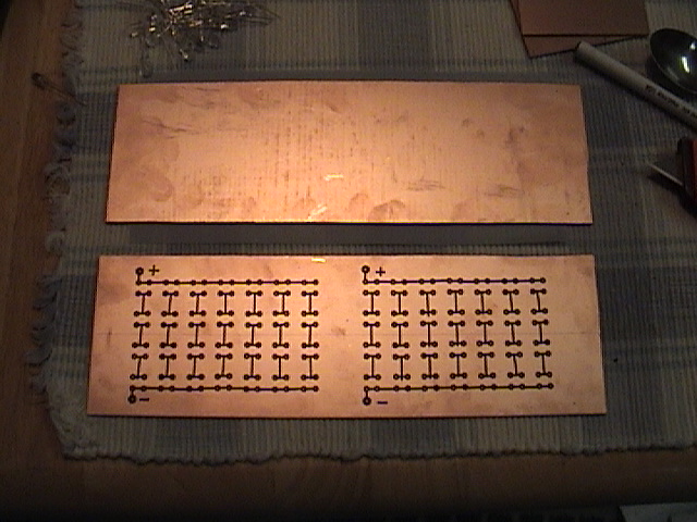
Posted by: smrz914 Jan 15 2004, 03:24 AM
The PCB started off as a 12x12 sheet. But I needed something like 14x6 to do it the way I wanted.
Attached image(s)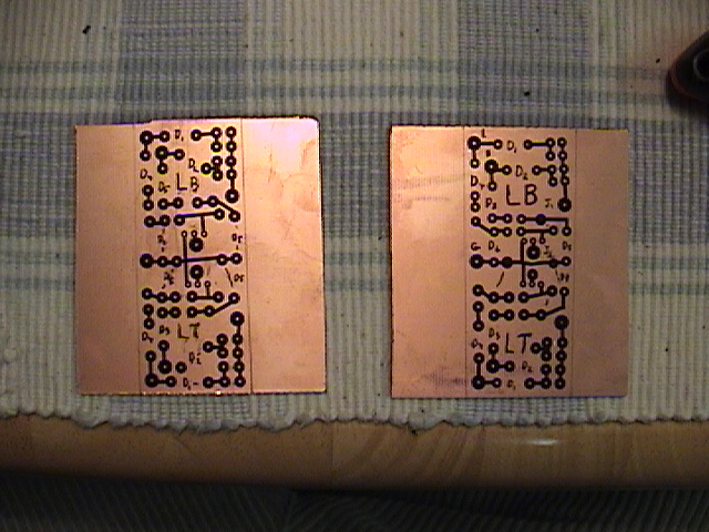
Posted by: ss6 Jan 15 2004, 07:03 AM
Paul,
Check out
http://www.expresspcb.com and http://www.pcb123.com
They supply inexpensive pcb's AND free layout software to make them. You draw them up (the software is easy), surface mount or through-hole, upload the design, and your boards show up in a fedex envelope 2 days later. There is really no reason to fab your own pcb's anymore with internet services like these guys. I've used expresspcb a lot, they have a "mini-board" deal, 3 boards for ~$60, just about the right size for your tail light project.
Posted by: zehrschnell914 Jan 15 2004, 01:35 PM
Sounds great Smrz. I would be interested in some. Will you be doing front turn signal/marker lights as well?
Mike
Posted by: tat2dphreak Jan 15 2004, 01:52 PM
![]()
this is a great idea, I'm glad someone was smart enough to think of it and work it out... keep us posted!!!
Posted by: smrz914 Jan 15 2004, 04:13 PM
I have one problem in making the kit. The taiilight housing has to be cut in order for the PCB to fit. Look at the pic, where you see the light coming through, that was closed off before. I will have new connector but it will require some work. If people don't mind modifying the taillight housing and adding in a new connector everything should work fine.
Attached image(s)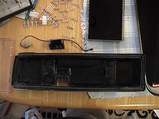
Posted by: smrz914 Jan 15 2004, 04:15 PM
close up of hole
Attached image(s)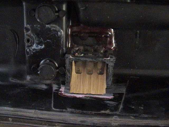
Posted by: smrz914 Jan 15 2004, 04:18 PM
I'll try the front turn signal after I know the rear works and I will also need to get different LEDs.
Part that was cut out.
Posted by: smrz914 Jan 15 2004, 04:18 PM
try that again
Posted by: smrz914 Jan 15 2004, 04:20 PM
keep pushing the wrong button
Attached image(s)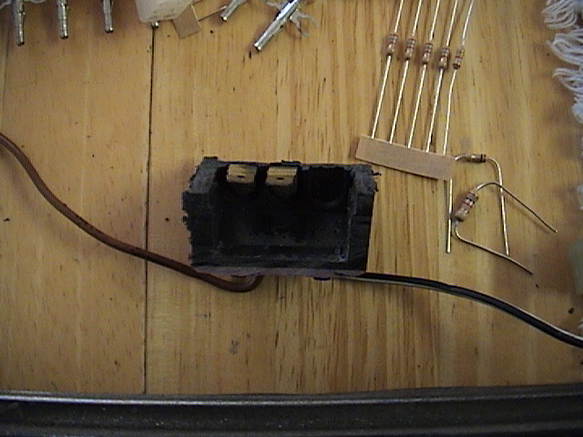
Posted by: zehrschnell914 Jan 15 2004, 05:48 PM
Sounds good to me. Post pics when they are done!
Powered by Invision Power Board (http://www.invisionboard.com)
© Invision Power Services (http://www.invisionpower.com)