Printable Version of Topic
Click here to view this topic in its original format
914World.com _ 914World Garage _ Suby-engined rustoration
Posted by: strawman Apr 18 2008, 12:19 AM
Hi All --
This is my second post, but I've been lurking on this fine website for a while now. I've wanted a 914 since I was in high school, but always seemed to stumble upon other projects... until recently.
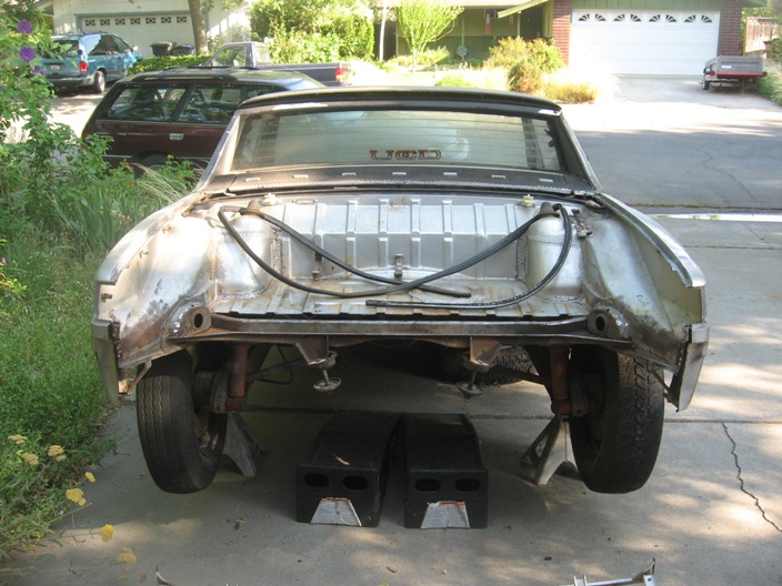
My neighbor gave me this 1973 Porsche 914 about a month ago. He told me he blew a head gasket and parked it in his parents' driveway in 1992. When his parents finally told him to move it or they were calling a local junkyard, he offered it to me since he knows I'm a gearhead. In for a penny, in for a pound...
I hauled it home, knowing that it has some rust issues in the battery area and rear trunk. But it appears to have never been in a wreck and it is complete. It turns out that an exhaust stud pulled, so he coulda fixed it for a couple hundred and probably kept another 914 from languishing but I guess all things happen for a reason (namely, so I would undertake this project!).
I sold the engine to a local Craigslister for use in his Meyers Manx dune buggy, and bought a wrecked but running 1993 Subaru Legacy turbo wagon. This is the closed-deck 2.2 liter engine, and 250 hp is easy with boost control and an open exhaust. I've already done a Subaru into a VW Vanagon and my daily driver is a 1992 Suby Legacy, so this won't be too much of a stretch for me. I plan to use the Suby 5-speed transmission (out of a 1998 Suby Forester) with the Aussie-sourced RWD elimination coupler and custom-mated 914/Suby axles.
I've got a suburban home with a crowded two-car garage (my 125 shifter kart and my daughter's FJA kart will likely get lonely!), a MIG welder, and a wide assortment of air/power/hand tools -- so the adventure begins! This project will likely take a year to finish, so please be patient.
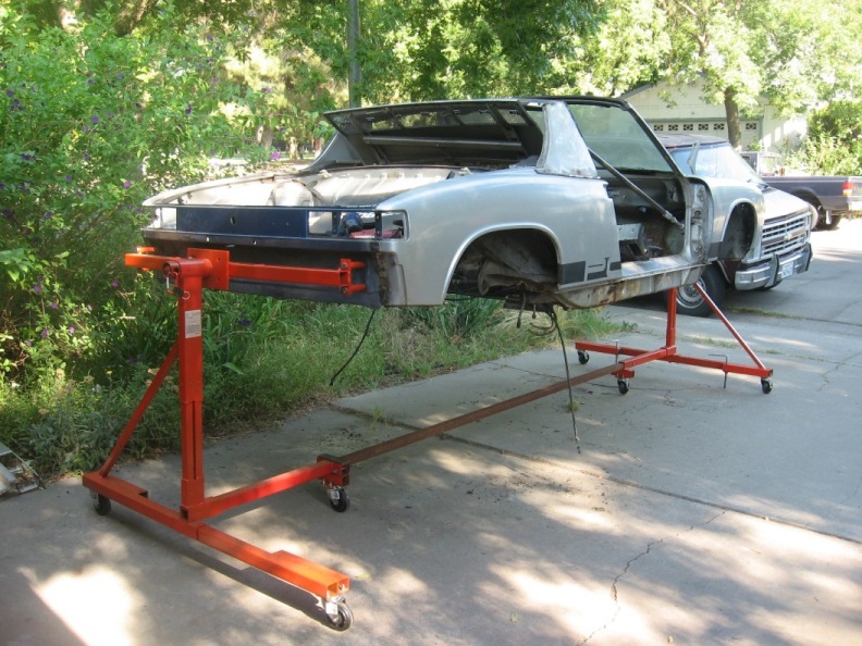
I've attached some pics of the car as found in the driveway, some rust areas and the rear trunk repairs I've started. I'll chronicle the build as I go, so feel free to chime in!
Geoff
Attached image(s)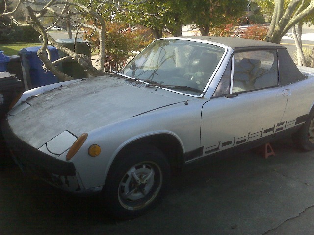
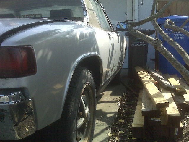
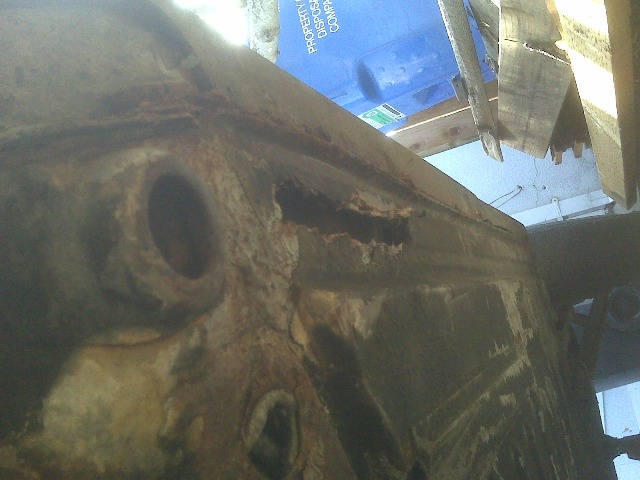
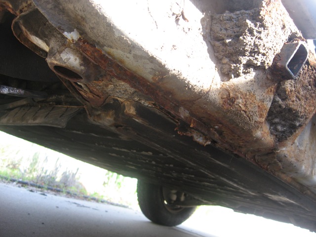
Posted by: strawman Apr 18 2008, 12:25 AM
More pics of the rust in/around the battery tray and passenger side long...
Notice the dirt packed around the jacking point. Yuck!
Attached image(s)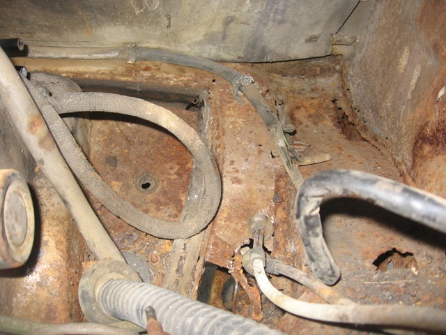
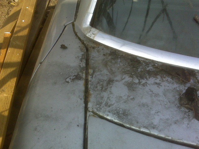
Posted by: strawman Apr 18 2008, 12:30 AM
Here are some pics of the front and rear trunks...
Note the standing water. More yuck!
Actually, when I opened the passenger side headlight bucket, I found that foul-smell that kept wafting up from the front of the car. I found a swamp caused by a plugged drain hole (sorry no pic). NAAAAASSSSTY!
Attached image(s)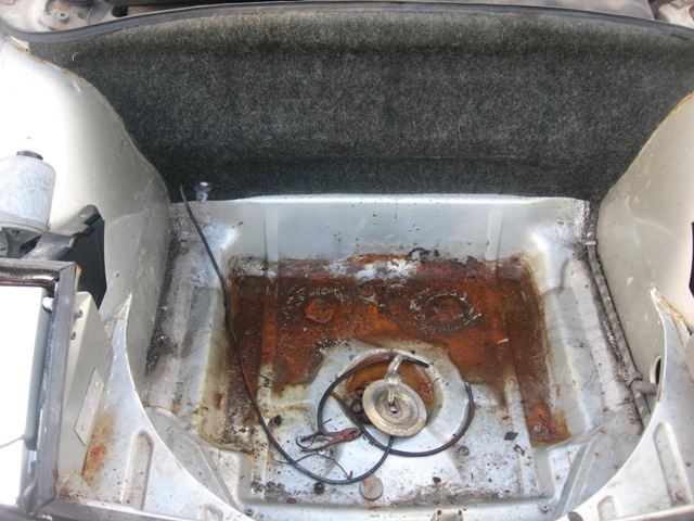
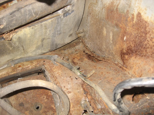
Posted by: strawman Apr 18 2008, 12:33 AM
Here are some pics of windshield/cowl area that'll need some attention.
The floors look strong (more pics to follow, once I scrape out the tar), and there is some rust bubbling under the sail vinyl and the rear trunk lid...
Attached image(s)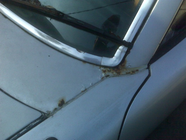
Posted by: strawman Apr 18 2008, 12:41 AM
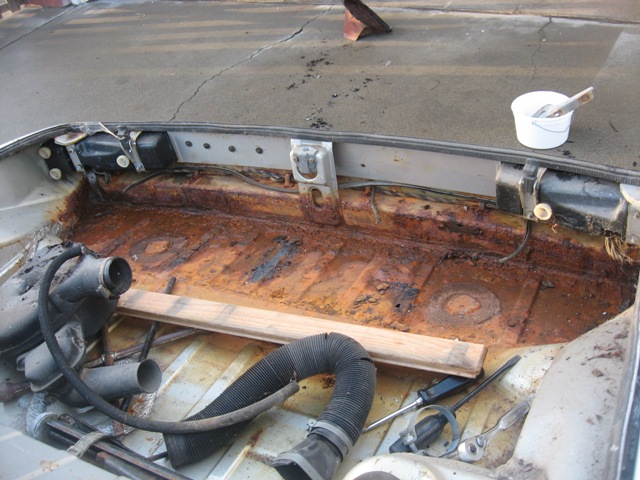
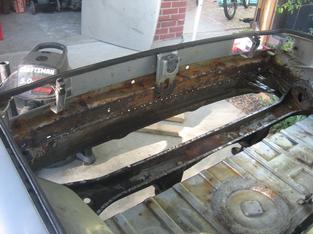
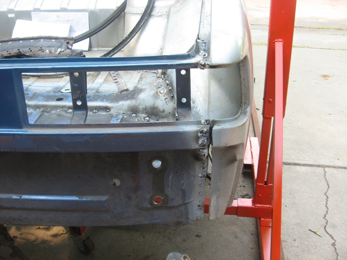
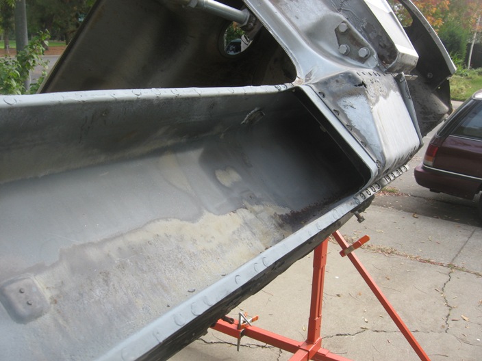
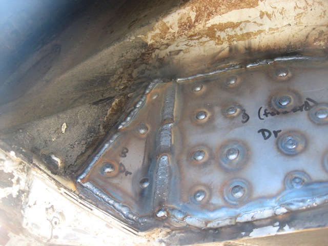
Okay, here are some pics of the rear trunk area. I started out using a 3/8" tri-point drill, but ended up using Harbor Freight spot-weld bits. The first HF bit lasted about 30 spot welds, the second bit lasted two spot welds and the third about 20 so far. For $3.95 apiece, tho, it was a bargain. I had to grind out a few spot welds in the rear corners because the space was too tight for the drill & bit and I had to cut out the trunk pan in one large piece and two smaller corner pieces.
I've already purchased an Auto Atlanta rear trunk replacement panel, as well as a rear suspension console. I'm not so happy with the fit of AA trunk panel; it fits pretty poorly around the left/right "humps." Looks like I'll need to section in pieces of sheetmetal to make it fit (notice the 1/2" gap at the forward edge of the humps in the later pics). It also sits higher against the rear panel than stock, so I'll have to rosette weld in the 1/8" holes I drilled through the rear panel.
Attached image(s)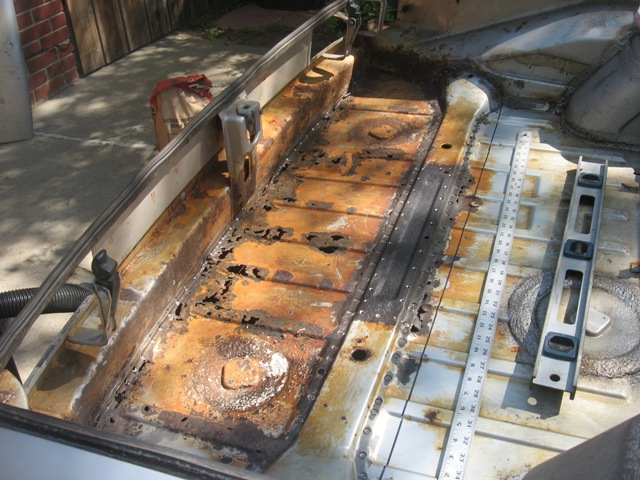
Posted by: strawman Apr 18 2008, 12:45 AM
More trunk pics...
Attached image(s)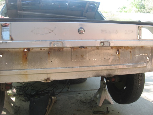
Posted by: strawman Apr 18 2008, 12:46 AM
More...
Attached image(s)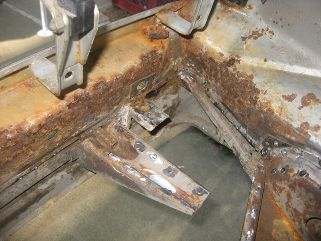
Posted by: strawman Apr 18 2008, 12:49 AM
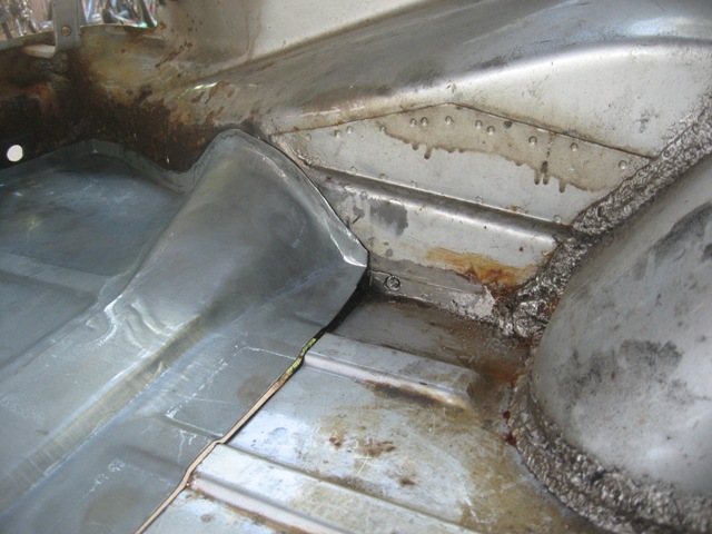
And some more, with the AA trunk pan mocked up...
Attached image(s)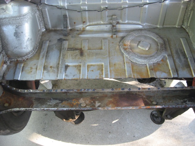

Posted by: strawman Apr 18 2008, 12:50 AM
Finally, here are some pics of the gaps near the forward portion of the humps...
Attached image(s)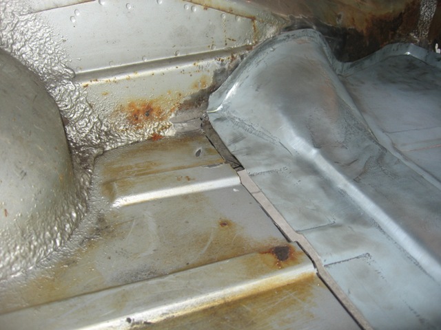
Posted by: strawman Apr 18 2008, 12:56 AM
I've ordered some POR-15 supplies and some Wurth Weld-Thru primer, but in the meantime I'll need to do some rust repair on the rear panel and try to massage the AA trunk pan into place. Once the rear trunk is shored up, I'll remove the suspension and get it up on a rotisserie to begin the frame repairs.
Anyone in the NorCal area have a rotisserie they want to give/sell/loan to me? I found some plans on this site that I'll build if that avenue doesn't work...
Finally a pic of me that my wife finds especially amusing. I always wanted to be an engine!
Stay tuned.
Attached image(s)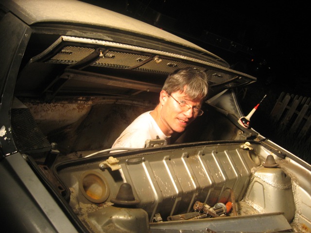
Posted by: charliew Apr 18 2008, 10:16 AM
Hi Strawman, Good work sofar, I hope you don't get discouraged on the rust challenges. I'm also accumulating all the subie stuff.
Mind explaining the 99 forester tranny choice? I have a 96tt tranny I have done the Bremar conv too and just got a helical lsd to put in it. I'm pretty sure I can make the spline adapter on the bremar conv. out of the old parts by welding them up. The plate is just that but their's is prettier. I kinda hate to tear up the center diff though. I was hoping the tt tranny would be stronger since it was one of the first higher hp versions. (260/280) I also have a 02 5k miles wrx tranny but it's a early version and supposedly has weaker gears that they updated in late 02.
My 914 is pretty rust free. You might consider while you are fighting the longs putting the cooling tubes in them and it might also add strength to the tub. You might even consider some 3x3 thinwall tubing to replace the long and save the money on the replacement parts. I haven't got a good answer on the front of the long for the radiator tubes into the front trunk.
I'll be watching, good luck.
I've used lots of por 15 products. I wish you could sandblast all the places that you find rusty and use PPG DP epoxy primer. Paint sticks to the epoxy primer much better than the por 15. I have a jeep truck that I have used a lot of por 15 on and am going to need to redo some of it. It's about 5 yrs old now. None of the rubber undercoating has stayed on over the por 14.
Charliew
Posted by: Zaney Apr 18 2008, 11:00 AM
Awesome start! I am going to dive into my Suby-rustoration after this summers WCC 08 meet here in the PNW. Hopefully by then some of the other fellow Scooby projects will have some products that I can purchase to complete the bolt in conversion.
Keep the pics coming! 
Posted by: strawman Apr 18 2008, 11:17 AM

Mind explaining the 99 forester tranny choice?
It is what came in my donor car. The PO replaced the stock wagon auto with a 5-speed transaxle & rear diff (4.11 gears, IIRC) out of a '98 Forester, which also uses a hydraulic clutch actuation system like the Legacy Turbo sedans. I'm considering picking up a FWD Suby trans, since it is cable-actuated and I would not have to buy the Bremar kit. But I can't find any info on NASIOC on the strength of that unit. Do you know?
I've used lots of por 15 products. I wish you could sandblast all the places that you find rusty and use PPG DP epoxy primer.
I've never personally used POR-15, but my old 4WD buddies swore by the stuff. But they generally used it on their frames to ward of the Utah salt. I have a HF pressurized sandblaster; I'll have to do some research on epoxy primers vs. POR-15 -- thanks for the tip.
You might consider while you are fighting the longs putting the cooling tubes in them and it might also add strength to the tub. You might even consider some 3x3 thinwall tubing to replace the long and save the money on the replacement parts. I haven't got a good answer on the front of the long for the radiator tubes into the front trunk.
I'll have to do some research on this, too. This is strictly a fun car, since I know I can't compete well against the big bucks SCCA SM2 autocross guys. So the 3x3 idea might have some merit. But how do you tie well into the rear longs with this setup?
Posted by: strawman Jul 9 2008, 12:04 PM
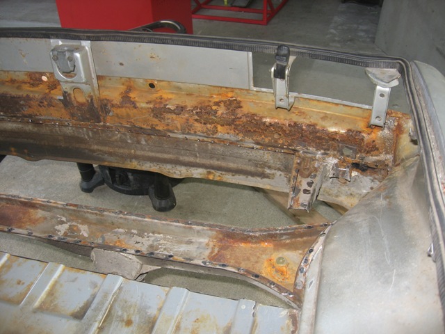
Been a while since I last posted, but I've been making some progress. I built a rotisserie, purchased the Bremar 2wd conversion kit for the AWD Subaru transmission, removed doors/suspensions/trunks, and got further into the rear trunk/panel rust repairs.
The original rear panel was too far gone, so I picked up a rear clip (thanks Echocanyons!) to replace the rear portion of the trunk floor and the rear panel. The rear panel is "pinched" between two panels at the factory, so I was forced to cut (vertically) a portion of the rear quarter panel "wrap-arounds" to get the old panel out and to install the replacement one. Pictures below provide a better idea...
Posted by: strawman Jul 9 2008, 12:16 PM
Here is a pic of the rear trunk/panel, ready for installation.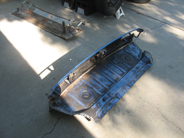
Voila, now it is tacked into place. I used Wurth Weld-Thru zinc primer on all joints (after using Marine Clean and Metal Prep to knock out the surface rust), but that made it very difficult to spark the welds. For subsequent welds, I think I'll clean off the Weld-Thru in those areas that will actually be welded.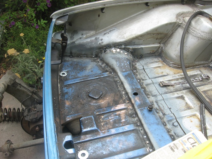
On the right of the lower picture, you can see one of the two the vertical pieces that I had to cut out of the quarter panel wrap-around in order to install the rear panel. It is "swiss-cheesed" from cutting the spot welds, but the compound bends suggest that I should repair it rather than trying to bend up a replacement piece. Most of it will be hidden behind the rear bumper anyway...
Posted by: strawman Jul 9 2008, 12:19 PM
Here are two closeup pics of the rear corners, that depict the vertical strips that were cut out.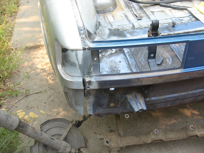
Posted by: strawman Jul 9 2008, 12:45 PM
Now for a pic of the rotisserie parts. I bought a couple of engine stands off Craigslist (one was purchased from a guy that lives only four doors down from my house!) -- I got one for $25 and the other for $30. I also bought another $100 of 2" x 2" x 1/8" square tubing, and got some scrap 1.5" for free that I'll use to connect the two stands (see the rusty piece on the ground?). I had some scrap steel sitting in my garage that I used to extend the height of the two stands, and used some leftover steel to triangulate the base/vertical portion. I hope to have a small beer/pizza party this weekend to lift the chassis onto the stands. 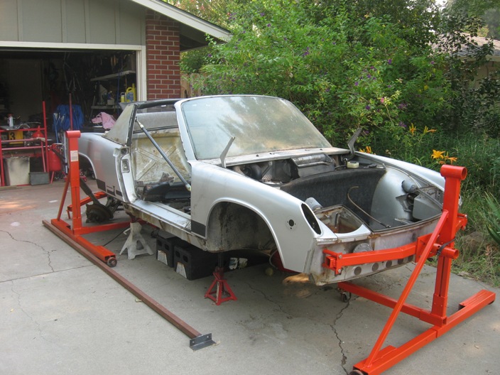
I'm planning on using the engine stand steel wheels to save cash on buying new casters. Anyone want to chime in to say this is a bad idea???
Yes, I'm an SF Giants fan, so I had to paint the rotisserie orange. I'll eventually paint the car orange, too.
You can also see the turnbuckle system I'm using. I bought two 3-point tractor connectors (one for each side) for $20/each at Tractor Supply Company. I then cut 'em in half and welded in some Schedule 40 pipe to extend them the proper length. I'm following Jeff Hail's lead by welding in the lower support to the kick panel so that I can install the doors to check gaps as I weld in the hellhole repair panels. I used the lefty-tighty heim joint for the upper mount, and used a 3/4" bolt welded onto angle steel for the lower mount. Here's a closeup of the upper mount: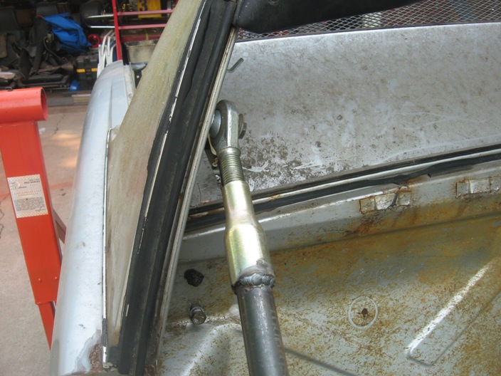
I've committed to the GT Flare / rocker group buy, so those will be welded in after the rust issues have been tackled. I also bought the Desert Hybrid chassis stiffening kit and trailing arm stiffening kit that'll be installed while the car is up in the air. Stay tuned!
Posted by: tdgray Jul 9 2008, 03:37 PM
Good work... keep it up... I've done worse and made it through... I'm sure you'll get there.
Posted by: strawman Jul 17 2008, 09:02 PM
Look what showed up today at my doorstep... the Bremar kit to convert my Subaru AWD 5-speed transmission to FWD. This item cost about $385 and arrived in less than two weeks from when I placed the order. More pics to follow once I begin digging in!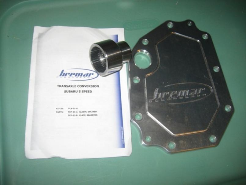
I didn't get a chance to get the car onto the vertical stands last weekend, bu tI hope to do so on Saturday. I'll post more pics soon...
Posted by: rick 918-S Jul 17 2008, 10:22 PM

![popcorn[1].gif](style_emoticons/default/popcorn[1].gif)
Posted by: strawman Jul 19 2008, 07:51 PM
Got the car up on the rotisserie today. Used my cherry picker to lift the rear, while three of us lifted the front and a neighbor slid the front stand onto the front mount. Then we just slid the rear stand onto the rear bracket.
Now I can finish up welding the rear trunk clip from the underside, and then begin replacing the rusty hellhole parts. Stay tuned!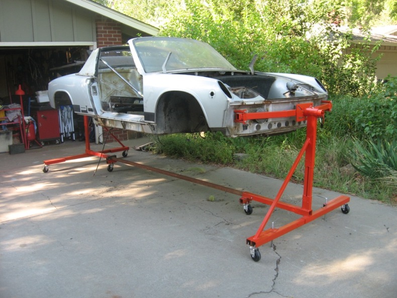
Posted by: strawman Aug 16 2008, 09:40 PM
It has been a while since I last posted, but I haven't been dormant. But first, a pic of what I like to call "Buzzing the Flight Tower"...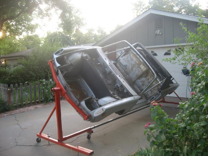
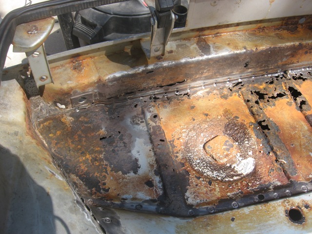
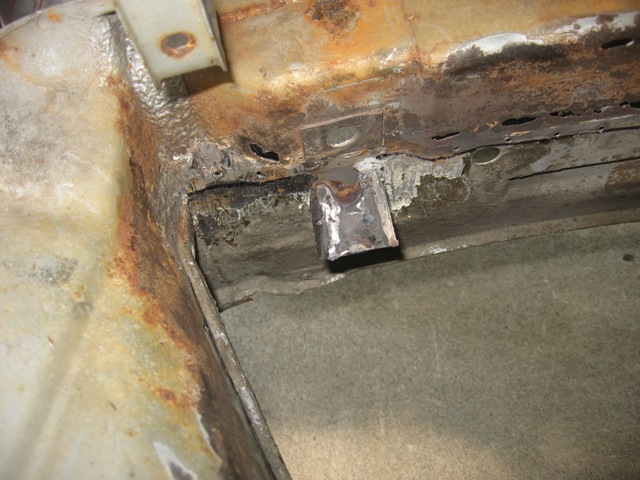
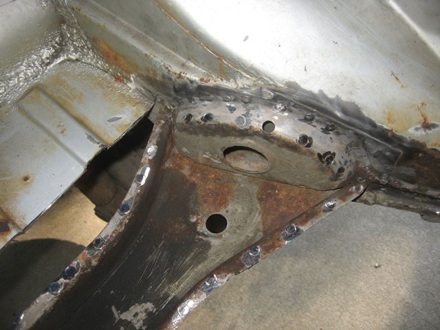
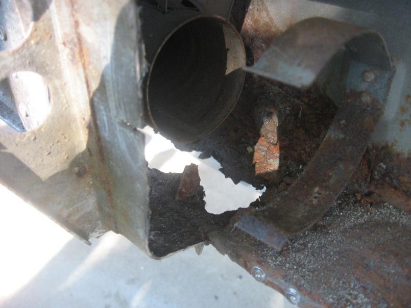
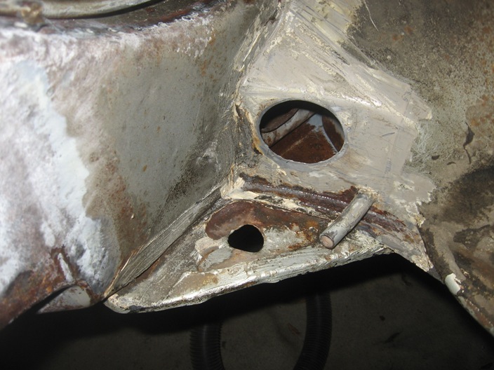
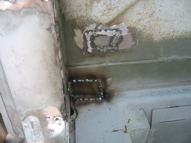
Unfortunately, I didnt' take very good pics of the passenger side long before I started digging in, but the inner suspension console was toast, as was the motor mount, and portions of long, firewall and passenger side "wall." Here is a pic from the top.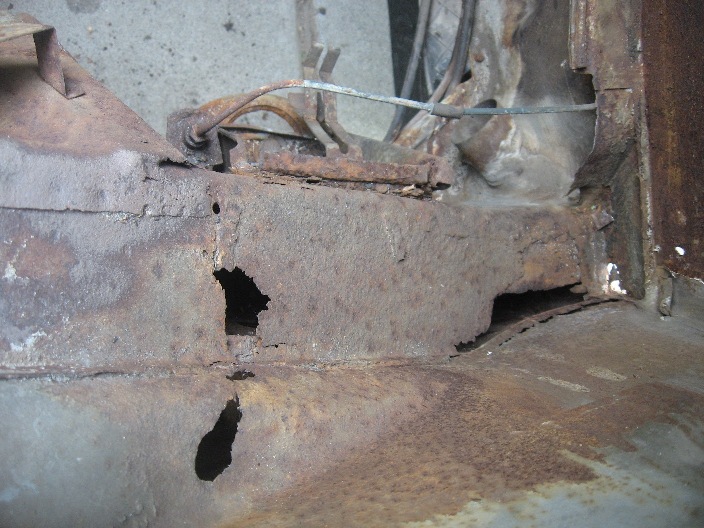
Here is a pic of the area I cut out... it includes the small connector piece to which I'll weld the larger inner patch piece. As you can see, the area has already been treated with POR15 Marine Clean and Metal Prep.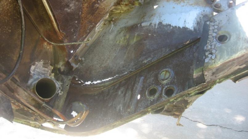
Posted by: strawman Aug 16 2008, 09:59 PM
Next up is a pic of the patch piece, made of 16 gauge steel. Since the factory piece used inner "ribs," I added these reinforcements made of 1" 14 ga. square tubing ripped into angle pieces. This pic shows the Metal Prep stage, prior to painting the inside with gray POR15.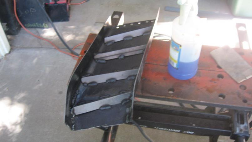
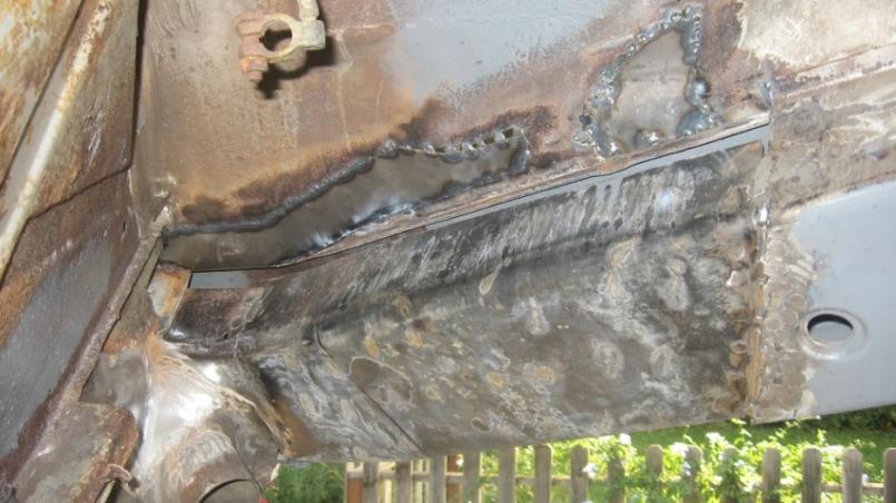
Since I'm using a rotisserie, I don't want to completely muck up the dimensions by cutting out too much at a time. So I'm replacing pieces in relatively small increments, and checking to see that the suspension jig I built still lines up as I go. Here is a pic of the patch during welding into the hole. 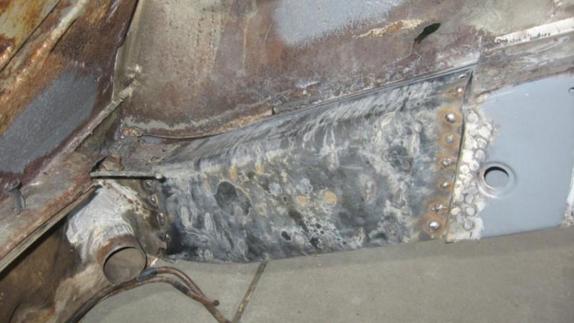
That piece will be covered with an 18 ga. outer shell, in order to attain the same thickness that the factory used (two pieces of 17 ga.). That outer shell will be welded in as soon as I provide a good foundation to weld. From a previous pic, you can see the "wall" has rusted out and portions need to be replaced -- and that area is necessary in order to install the "outer" shell.
Here is a pic of the area I've cut out to complete this next phase.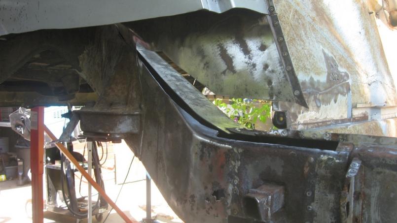
Posted by: strawman Aug 16 2008, 10:25 PM
Here is a pic of lower patch piece, made of 18 ga. steel. I forgot to take a pic of the upper patch piece.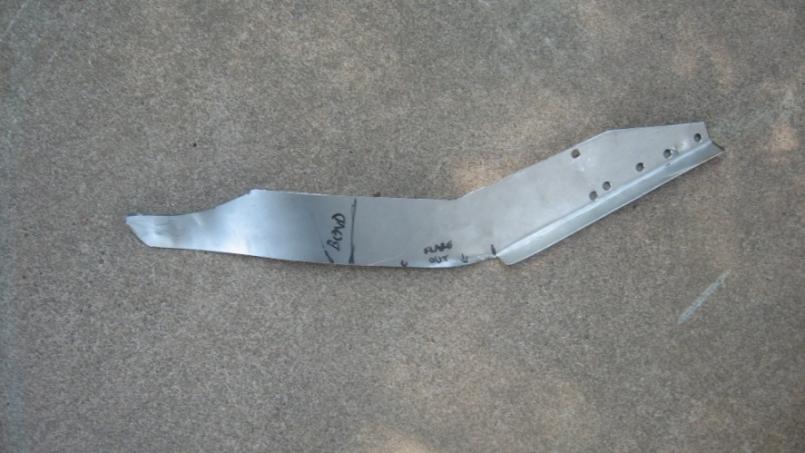
When I get going, it is tough to remember to take pics... so here are two pics of the patches that were needed. It was almost 100 degrees today, so I shoulda taken pics while I took water (and beer!) breaks while the welds cooled...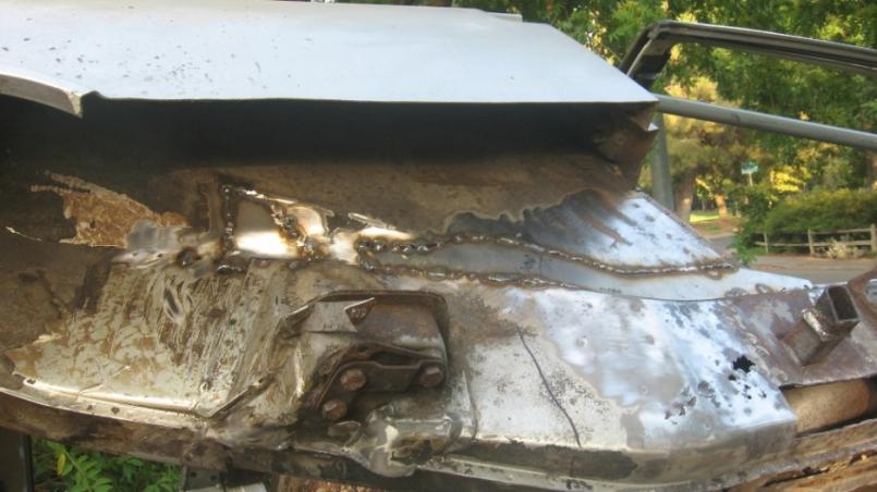
I forgot to mention in the previous post above that I cut out the lower portion of the passenger side quarter panel in order to get to the various rust damage areas hidden by that piece. I also have a sizable rust hole where the sail panel meets the quarter panel.
Porsche (Karmann?) really screwed the pooch when they decided to put that nasty-ass foam and seam sealer in places where the tires would kick up water... I've spent too many hours picking that  out.
out.
I hope to weld in the outer shell over the inner upper long this week, and to cut out / patch the outside long (where you can see the rust holes!). Next up is to install the inner suspension console that I bought from Auto Atlanta a few weeks ago. I also ordered a new sill plate and outer long from AA this week; still awaiting shipping confirmation from George... and I'm part of the GT Flare group buy, too, so I'll be a busy guy in the coming weeks/months!
Stay tuned...
Posted by: Hammy Aug 17 2008, 04:06 AM
Awesome progress.
How are you planning on mounting your Suby engine? Sorry if you mentioned it already, I only skimmed-read.
Posted by: strawman Aug 21 2008, 11:33 PM
How are you planning on mounting your Suby engine? Sorry if you mentioned it already, I only skimmed-read.
I haven't yet nailed that down. I might go with the Smallcar setup, since I used that for my prior Suby-powered Vanagon project and liked the build quality. Of course, I'm a CSOB, so I might try to fab something myself.
The slate is pretty clean (at least on the passenger side right now, since I had to cut that side's motor mount out!), so I'll have to finish with the rust repairs before I figure out those details.
Geoff
Posted by: plymouth37 Aug 21 2008, 11:44 PM
Very cool! Looking forward to following your progress!
Posted by: roadster fan Aug 22 2008, 06:54 AM
Nice work, makes me wanna go fire up the mig and tackle some on my project. Keep the updates coming
Jim 
Posted by: strawman Sep 26 2008, 11:35 AM
It has been a while since I last posted and work has required more time than I would otherwise like but I haven't totally ignored my teener. Unfortunately, I didn't take a lot of time to take many pictures... but here are a few of my continuing effort of shoring up the upper/inner long & hellhole.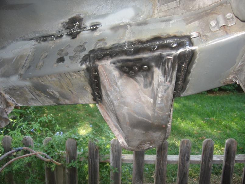
In this pic, you can see the outer 18 gauge "shell" that I bent up to cover the inner 16 gauge piece described above. This outer shell is tied into the inner piece and the fender wall. You can also see the AA inner suspension console. You can also see that I had to plug the suspension mounting hole, since that hole didn't line up exactly with my jig... which you can see below.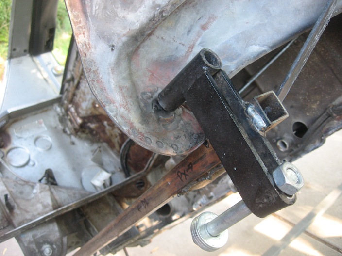
The jig ties into the outer suspension holes, the inner suspension console on the driver's side, and the driver's side motor mount. Ignore bolt/washers/nut that is being temporarily stored in the slot; that bolt is lined up with the "tube" and eventual new hole in the console (two washers are spaced between the tube and console).
It should be noted that AA's inner suspension console cannot be blamed for this misalignment -- I fabbed up my own upper/inner long replacement, so the suspension console required some massaging to fit, and the mounting hole was off by about 1/4".
Posted by: strawman Sep 26 2008, 11:44 AM
Here is another pic of the jig...
Here is a pic of the first reinforcement piece that I fabbed up to tie in the rear portion of inner suspension console to the long; I still have to fab up a small piece to tie in the inner and outer suspension consoles, and some pieces to tie in the front portion of the inner and outer consoles.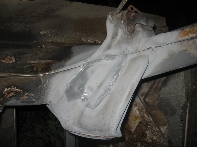
A couple of weeks ago, I received an inner rocker panel from AA, as well as a new sill plate, jacking post kit and a floor pan triangle. Yesterday I received my fender flares from the AA group buy, as well as an Engman stiffening kit that I bought from a member on this board. I'm hoping to finish up the hellhole work and outer/upper long repairs this weekend. Then I'll begin replacing the inner rocker panel & sill plate. Gonna be making some more sparks soon!
I bought a new-to-me 220v compressor & Devilbiss HVLP spray gun so that I can begin some paint work. Anyone near the Sacramento area want to buy a Craftsman 33-gal 110v compressor?
Posted by: pktzygt Oct 2 2008, 02:06 PM
OK, this and a few other treads are my motivation to get serious about buying a 914. I feared the rust repair for a while, but I'm starting to look foward to the challenge. I'm about 3 days away from selling my WRX and then seriously looking for a 914. Keep the updates coming, I'll be following closely.
Posted by: FourBlades Oct 2 2008, 07:47 PM
Nice work!  Take more pictures, you will be glad later.
John
Posted by: rick 918-S Oct 3 2008, 06:11 PM
Posted by: tronporsche Oct 3 2008, 06:51 PM
You will no doubt be able to be one of the guys that says "I built this car" !!!!!! Good work.
Posted by: strawman Nov 16 2008, 11:16 PM
Been a while since my last post, but I've made some pretty good progress. Per the pic below, I've finished up the inner suspension console install.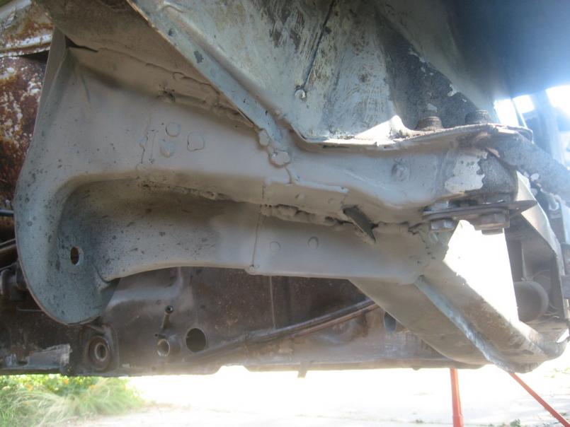
Here is a pic of the passenger side long, open for all the world to see...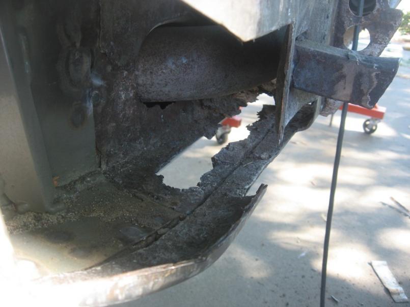
Posted by: strawman Nov 16 2008, 11:21 PM
Next up are some other pics of the passenger side long and the state of repairs necessary...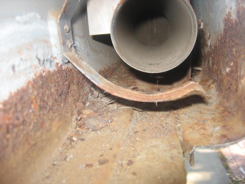
Posted by: strawman Nov 16 2008, 11:34 PM
I sandblasted the entire inner long to get down to bare metal. Since I'm using a water cooled Suby engine, I have removed the stock heater tubes. Here are some pics of the long without the tube, including the lower rear patch panel. 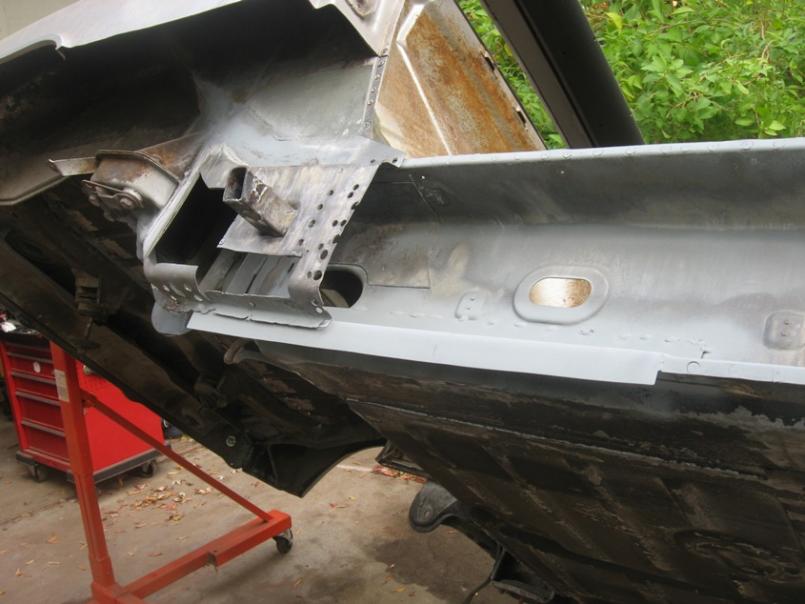
In the pic below, note the new lower seat belt attachment -- I pulled my hair out trying to find a tap to chase the threads after welding it in... until I realized that it is not metric (D'oh!). You'll also note the piece welded in behind the jack post. I sandwiched 16ga and 18ga sheetmetal to equate to the two pieces of 17ga used by the factory in that area, and bent it to fill in the rusty outer piece. I neglected to take a pic of the masterful (if I do say so, myself!) piece I hammered out to replace the compound bend where the long makes the swoop up toward the rear.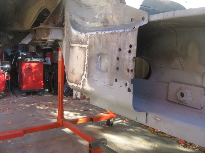
Posted by: strawman Nov 16 2008, 11:53 PM
Next up is a pic of the jack post, followed by the inner (outer?) piece sourced from AA. The second pic also shows the jack post support, as well as the hole cut into the forward section just below the door hinge area.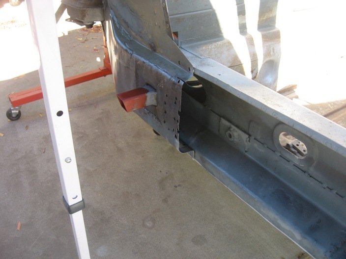
The inner piece was sectioned in just below/behind the door hinge area. I used a Miller spot welder to make the joins along the upper and lower seam. Use of that device was a godsend -- it made quick work of it and kept heat input into the chassis less intense in comparison to if I had to rosette weld that sucker on.
Gotta love the mid-November heat wave in NorCal -- it was over 70 yesterday and today, and I was sweating!!
I welded in a patch for the hole forward of the AA piece, but it got too dark for good pics. Next up is welding in the Engman chassis stiffening kit, and then the GT chassis stiffening kit and trailing arm reinforcement kit (from Desert Hybrids). I'll need to read up on the GT stiffening kit, as a couple of the pieces that tie into the suspension console look like a bear to correctly form. Anyone have a suggested thread to peruse?
BTW, I picked up a complete 911 suspension last weekend. I got it for $600, including Bilstein sports, alloy calipers, 1" wheel spacers and stock torsion bars -- it came off a late 70's turbo.
I also bought a bunch of paint supplies from Rainbow Supply in Woodland, CA to strip the paint, epoxy primer the chassis, and to practice a full paint job (PPG Omni 2-stage) on my Subaru Legacy daily driver. I won a fire fighter breathing apparatus on Ebay a few weeks ago that I'll use as a basis for a home-brewed fresh air system while painting the nasty isocynates.
Posted by: FourBlades Nov 17 2008, 08:33 AM
Beautiful work dude!
Keep it going for us resto junkies! 
John
Posted by: Zaney Nov 17 2008, 11:23 AM
Awesome work!
Make sure that breathing apparatus still makes a good seal and positive pressure before wearing in the fumes.
If you are unfamilar with it then, drop by your local FD (with some treats too) and ask some questions about your BA. I'm sure that most firefighters would be more than willing to answer questions about your new toy! 
And if you can't find any local then, myself or other smokeeaters on this board can help you out!
Nate
Posted by: strawman Dec 2 2008, 11:32 PM
Had all of last week off work, but we had family in town... so I only got to work on the car last Saturday and Sunday. Got a lot done and took pics on Saturday, which I'll show below.
First up are two pics of the driver side engine bay, showing removal of the engine bay seal channel. I first sawzalled large pieces off, then attacked the spotwelds. Instead of using the PITA spotweld cutter (which sometimes pokes thru the base metal!), I used a round-head burr in my air grinder to weaken the spotweld and then tore the metal in small strips using Vise-Grips. Way faster. The second pic also shows the hole where the heater tube entered the long; I ground that area flush, since I'll be covering that hole and tying in the rear firewall to the long with a piece of 16 ga.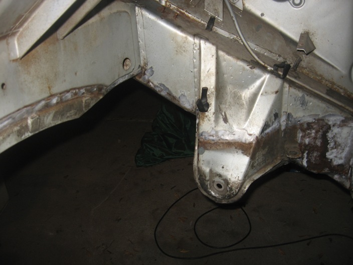
Next up is the passenger side engine bay, which depicts the repairs I made to the hell hole. I still need to ground down the heater tube hole lip and install the reinforcement discussed above.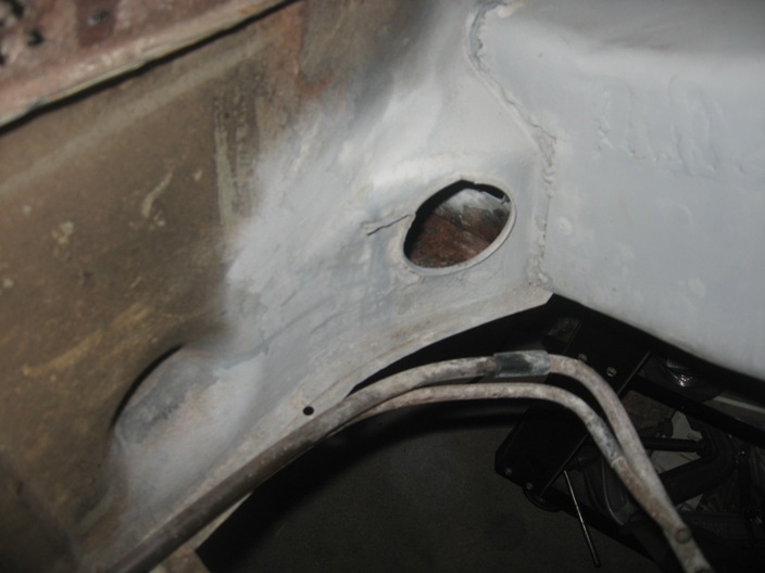
Posted by: strawman Dec 3 2008, 12:13 AM
On Sunday, I finished up welding in the rear trunk floor and removing most of the remaining seam sealer from that area. I also finished up welding in the final patch on the forward passenger side outer long (as described above).
I picked up some ESAB Easy-Grind .023 MIG wire, and I like it... it does seem to grind down easier than the standard ER70S-6 wire I was using. Flapper wheels on a 4.5" angle grinder do a good job knocking it down, whereas the other wire seemed to need abrasive wheels.
I also finished up the removal of the heater tube from the driver side long. There is no rust through on this side, which was a welcome relief after spending so much time on the passenger side long repairs. The pic below depicts the hole I had to cut in the forward portion of the long to remove the heater tube. The pic also shows the area I sandblasted, Marine-Cleaned, Metal-Ready-ed and then covered in POR15. 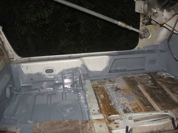
Although not shown in a picture yet, that whole area of the driver side long has already been patched and covered by the Engman long stiffening kit... unfortunately, the rechargeable batteries in my digital camera died and I, too, ran out of steam.
Gotta say -- even with the car on a rotisserie -- welding in the Engman kit takes a lot of patience and you're best advised to do some serious stretching before attempting to weld in all those rosettes. I spent the better part of two hours trimming the three pieces to fit just right, and another 90 minutes welding in only the driver's side (wedge myself through the chassis brace, weld, extricate myself while catching my welding helmet on the brace, curse like a sailor, blow compressed air on it; repeat about a hundred times...). I knew I was "done for" when I reached for a beer from the fridge after finishing the last rosette weld and my upper right oblique muscle locked up!
I won't be able to work on the car until the middle of the month, when I'll try to finish up the Engman kit installation. I'll post more pics soon.
Posted by: FourBlades Dec 3 2008, 08:10 AM
Looking good.
You made some great progress.
John
Posted by: Root_Werks Dec 3 2008, 09:32 AM
Wow! Great work, I can't believe I didn't see this thread earlier. Keep the progress coming!
Posted by: my928s4 Dec 3 2008, 11:44 AM
Nice fabrication work, you have given me some ideas for my fixer upper. Keep it up !
Chris
Posted by: strawman Jan 10 2009, 10:38 PM
Been a while since I posted, and work/family has gotten in the way of big progress, but I haven't been totally dormant. Since my last post, I finished up the Engman kit. Unfortunately, I didn't take any pictures of the progess.
I started the GT stiffening kit that I purchased from Desert Hybrids, as well as the trailing arm stiffening kit. Neither of these kits is drilled or pre-bent, and the instructions were not very helpful. Nonetheless, I found some some good guidance on this site (duh!). The passenger side was made a lot easier by removal of the lower/forward portion of the rear quarter panel.
Rear portion, including part of outer suspension console: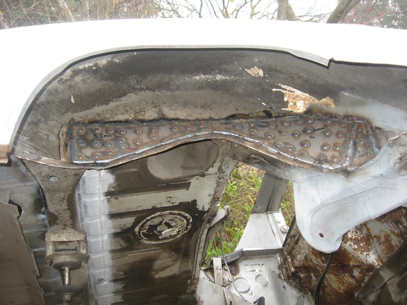
Far forward portion, by the jack post: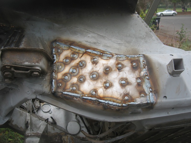
Here's a pic of of everything ground down: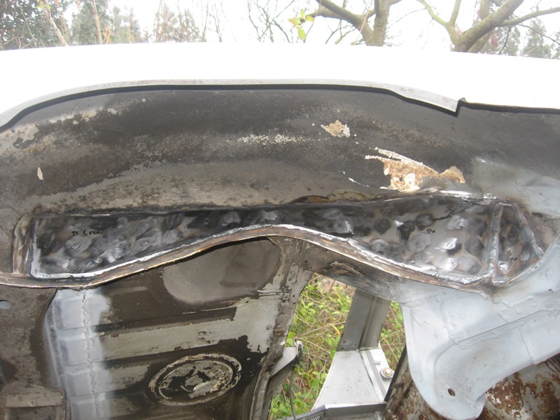
Posted by: strawman Jan 10 2009, 10:47 PM
Here's some pics of the driver's side. As I got deeper into this portion of job, I realized that the jack post was too far gone. So I cut that portion out and just won a replacement on Ebay.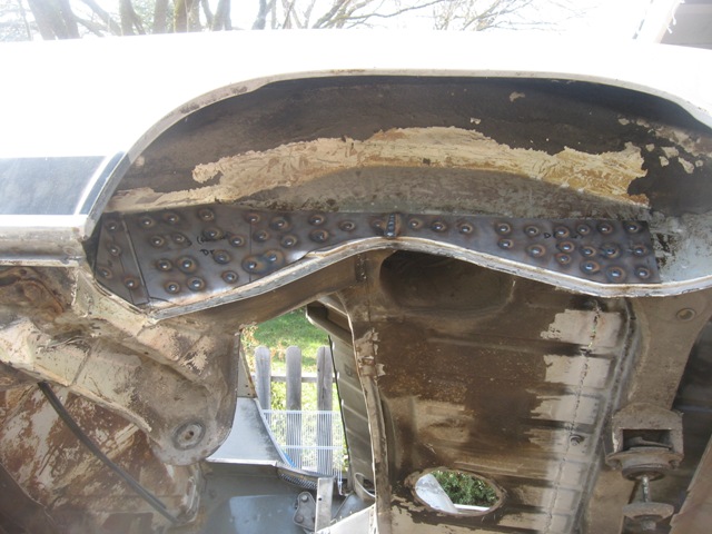
Here is a pic of the jack post half-way removed. Getting the upper spot welds out was a bee-otch, but the burr bit in my die grinder helped knock it out. Fortunately, there is no rust through, so I'll treat it and weld in the new piece.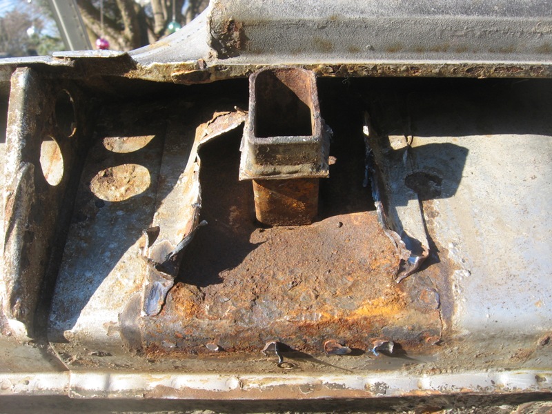
Posted by: strawman Jan 10 2009, 11:02 PM
Finally, here's some of the trailing arm stiffening kit install. I still have to weld the outer seams and clean up the rosette welds.
First up is one arm, smoothed, weld-thru primered and ready for the install.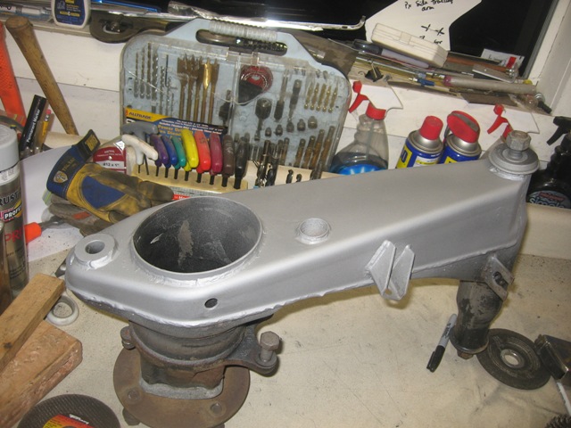
Next up is the plate, drilled and weld-thru primered.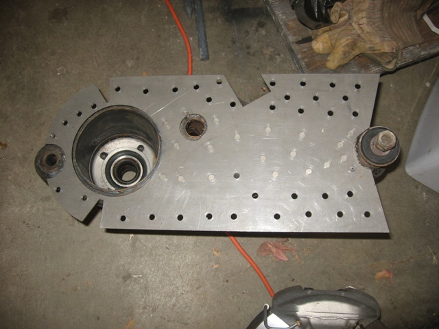
Here are both arms, with the plates rosette welded and ready for seam welding.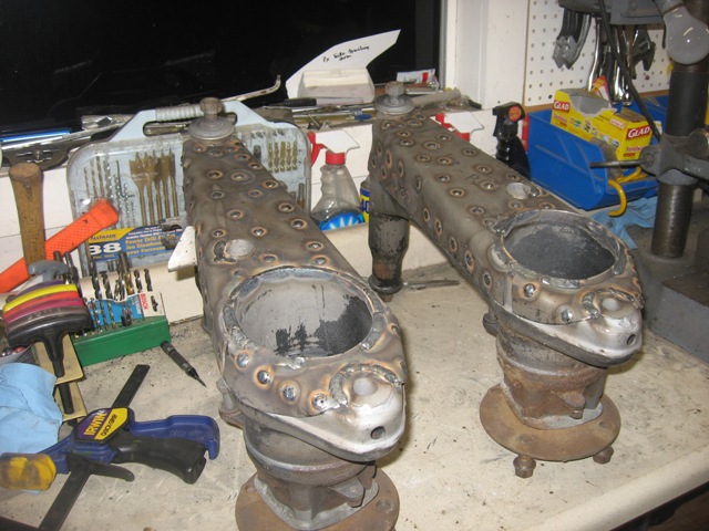
Finally, here is a pic of the underside GT stiffening kit on the passenger side. That one was the most difficult and it took a lot of muscle/grunting/swearing to bend it in to shape. 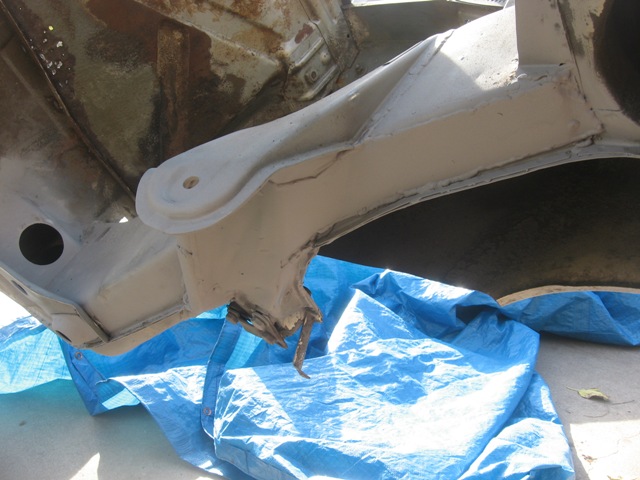
I really recommend cutting out templates of each piece in posterboard prior to drilling the holes... I had to fill-in a couple holes that the "instructions" otherwise suggested would be over solid metal. The template also helps you pre-bend the pieces. I believe that is most important on the trailing arm kits, since you want to make sure the rosette welds are in places that will help you bend the sides over. Does that make sense?
I'm heading to DC for work for a week, but I hope to finish up the trailing arms and the GT stiffening kit next weekend. Happy New Year!
Posted by: jc914 Jan 11 2009, 12:13 PM
Nice work
Posted by: strawman Jan 21 2009, 11:31 PM
The AA rocker covers that I bought as part of the GT flare group buy arrived late last week, as well as a few Ebay items that I won (jack post kit, poly trailing arm bushings and bump steer kit). I also had a chance to spend some quality time with the car on MLK, Jr. Day. In short, I finished cutting out the old driver's side jack post, installed the new one, and finished up welding in the GT Stiffening kit on the driver's side.
First up is a pic of the jack post welded onto the long, complete with SEM weld-thru primer covering everything. The welds match what the factory did (only along the vertical sides):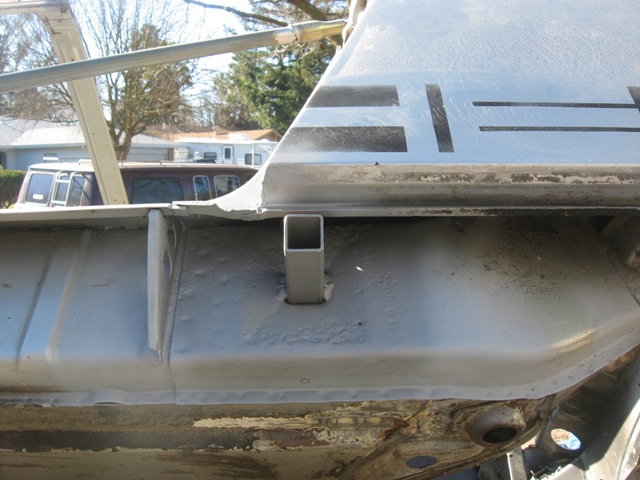
Next up is the jack post "cover." I found the only way to install it without removing the lower/forward quarter panel was to cut the upper/forward corner of the cover, and flatten out the bend that wraps over the top of the long. Maybe a pic would better explain this...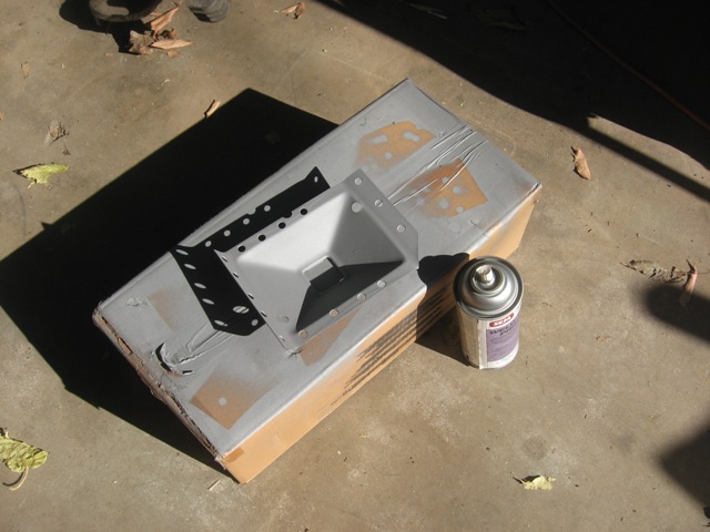
After rosette welding the cover to the long and welding along the post/cover joint, I was able to hammer down the upper edge and finish up the rosette welds along on the top. Here is a pic of the completed installation: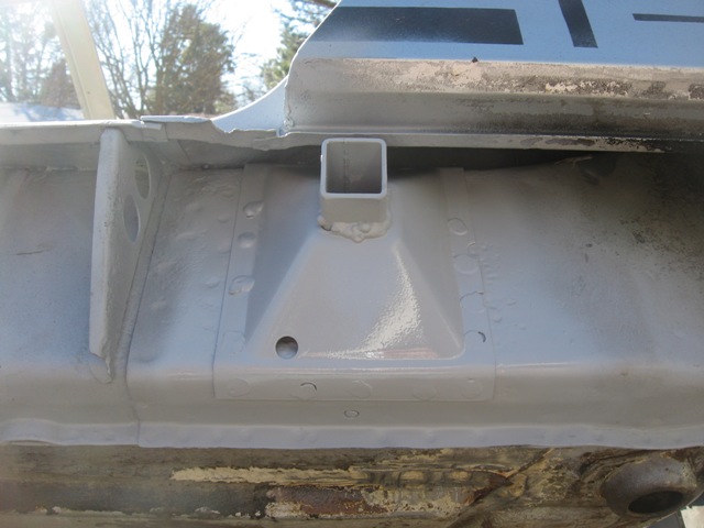
Next up is completion of the GT stiffening kit that was begun and chronicled earlier. A pic of that effort: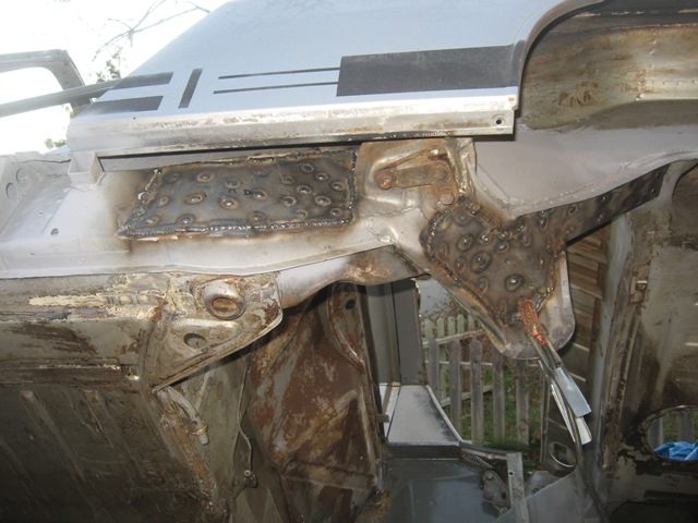
I still have to grind down the welds to make it look purty. I also spent about 4 hours scraping off the tar undercoat from most of the underside and driver's side inner fenderwells. I still have about four hours to finish the underside and the passenger side inner fenderwells. I can't imagine doing that without a rotisserie!
Next up is fixing the rust in the windshield area, then fix some rust holes in the sail panel area on both sides, then some frunk rubber channel rust repairs, then reinstalling the lower/forward passenger side quarter panel that I cut out to do the hell hole repairs, then two small firewall rust hole repairs, then welding in the passenger side long sill, etc. This list might seem never-ending to some, but I am making progress -- and that feels good. In fact, this project is cathartic for me and helps me deal with the stress of work/life/etc.
Unfortunately, my left hip is failing due to advanced osteoarthritis (and I'm only 42!), so I've scheduled surgery in late February to have it replaced, too. My right one was replaced in October 2007, and it is about 95% healed, so I'm confident this surgery will go just as well. So I won't be able to do any heavy lifting or acrobatics (i.e., welding upside down!) for a few months. Over the next few weeks, I'll try to set up projects that I can do on the workbench -- things like finalize the shifting mechanism, grind down welds on the reinforced trailing arms, new gaskets on Suby engine, etc. during my rehab. I might need to convince my wife to help move some things around to keep things moving along, which might pique her interest in this project (but I'm not holding my breath!).
Posted by: charliew Jan 22 2009, 01:12 PM
My wife seems afraid of my shop which is ok to me. She usually just puts her head in the door to yell at me. She is a good cook though and babies me and my sons and dogs so I only yell back a little. I'm 63 and my right hip is sometimes a bother but my knees are great. My dad had hip and knee surgery and he said the knee is tougher than the hip. I do have a uncle that he finally ended up with no hip after three surgerys. He still goes strong, riding a mower and swimming, driving and all. I had ulcer surgery in the mid 80's and pulled a stitch 8 days after surgery (the first day home from the hospital) laying on my back under the dash of a jeep pickup doing a sbc install. Good luck.
Posted by: Zaney Jan 22 2009, 03:22 PM
Geoff,
Could you post a picture of the "burr bit" that you used for grinding down the hard to get spot welds? I am in the middle of my passenger side woes and could use any and all tips and tools to do a good job.
Awesome Fab and Welding work!
Thanks,
Nate
Posted by: charliew Jan 24 2009, 01:19 PM
A burr is a term for a carbide bit that fits in a air tool. The ones I use for porting heads come in different shaft lengths and 1/4 shaft size. They have many different shapes and are good for many uses. When you use them on aluminum you will need a lubricant to keep the aluminum from sticking to the cutter. I don't remember the terminology but they have a coarse and finer tooth cutter for different materials. Finer for harder materials and coarse for the softer materials. You can get a set or buy them individually.
Posted by: strawman Jan 25 2009, 10:26 PM
A burr is a term for a carbide bit that fits in a air tool. The ones I use for porting heads come in different shaft lengths and 1/4 shaft size. They have many different shapes and are good for many uses. When you use them on aluminum you will need a lubricant to keep the aluminum from sticking to the cutter. I don't remember the terminology but they have a coarse and finer tooth cutter for different materials. Finer for harder materials and coarse for the softer materials. You can get a set or buy them individually.
Yup, Charlie beat me to the punch. I bought a set that includes a "ball" end bit, a straight bit, and a "tree" tapered end bit. The ball end bit is also great for weakening spot welds if you're tossing the removed panel piece. Here's some pics of typical bits:
http://www.carbidebur.com/shapes/burs.htm
If memory serves, I bought my 3-piece set at Sears about three years ago...
Geoff
Posted by: strawman Jan 25 2009, 10:54 PM
I bought a 1969 911 rear suspension/brake system today for $75 (I love Craigslist!). The purchase included the suspension arms, parking brakes & cables, calipers and non-vented rotors. Now I have almost everything I need for my 5-bolt conversion both front and rear.
Below are some pics of the pieces I will use on my setup, based on Paul Sayegh's write-up in the February 2009 edition of Excellence magazine. Excellent article, by the way -- and very timely! Unfortunately, my budget won't allow the use of the Porsche "reds" calipers that Paul used...
Pic before tearing everything apart.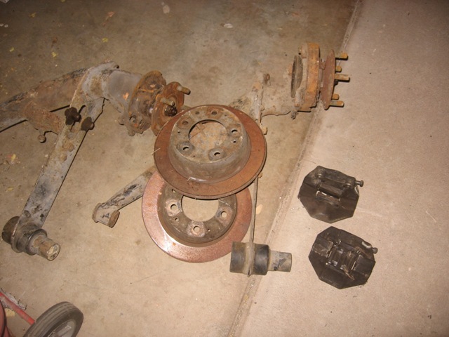
Here's a pic of the components I'll use. I have the backing plates, too, but I forgot to include them in the photo. Obviously, I still need to remove the parking brake pieces from the 911 "banana" arm.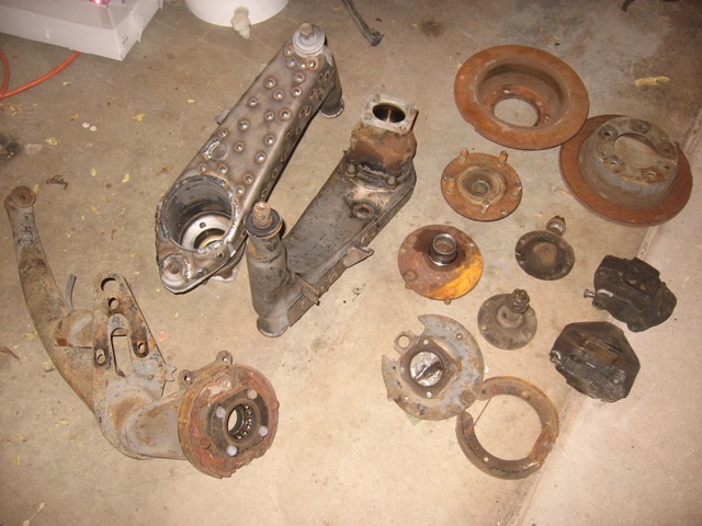
Some of these pieces are pretty rusty, but nothing cancerous/terminal. Like I'm scared of rust, tho! I'm thinking I'll replace some of the hardware with new and get the remainder plated. I'm hoping to upgrade to vented rotors, too, but I'll need to research my options for spacing/widening the calipers to fit 'em.
Fun, fun!!!
Posted by: strawman Feb 18 2009, 11:04 AM
I picked up a 1976 911 roller for parts a couple of weeks ago -- primarily for the fake Fuchs (it turns out they're only 15x7  ), Porsche rear reflector, and to get the rim-centering rear hubs for my 5-bolt rear suspension conversion.
I have been busy stripping parts to sell (I've actually netted money for my project on this deal  ), so I haven't worked on the 914 in a while. Here are a couple of pics of that hulk:
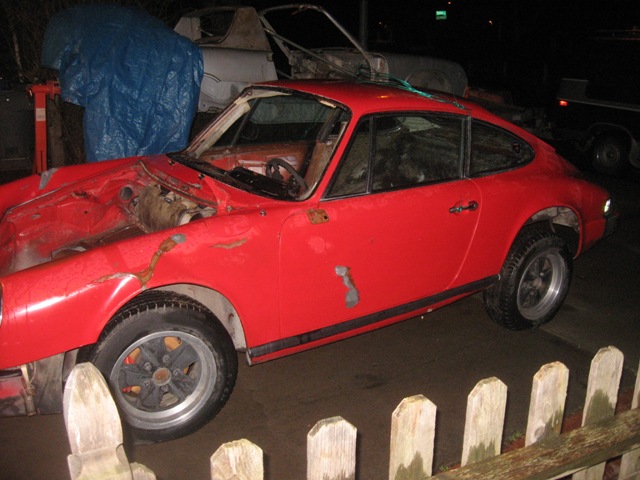
This means that I'll have a spare set of 1969-73 hubs, brakes, rotors (non-vented) and parking brakes (shoes, hardware and cables). Anyone interested? I paid $75, so I'd want the same... I'll put this in the Classified section later, but I thought I'd let any bored souls who have been following this thread have a crack at this setup first. PM me if you're interested.
My hip replacement surgery is tomorrow morning, so I'll be in lala land for the next few days and prolly won't be able to respond to PMs for a week.
Posted by: dlo914 Feb 18 2009, 12:46 PM
Great work so far! Will definitely follow your project since a buddy of mine wants to do the same and start a suby project.
Posted by: strawman Apr 26 2009, 09:41 PM
My hip replacement surgery went well, and I've got about 75% range of motion back. I am not supposed to do much heavy lifting, so I've been puttering around the garage and staring longingly at my teener. So I couldn't take it anymore and dove back in yesterday and part of today.
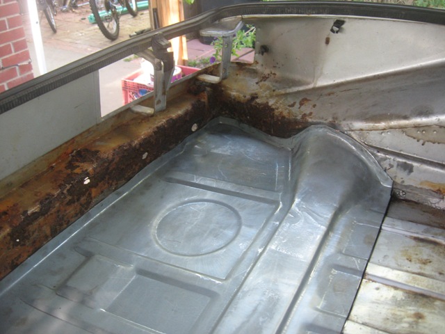
First up is the rust on the driver side sail panel. As you can see, it rusted through...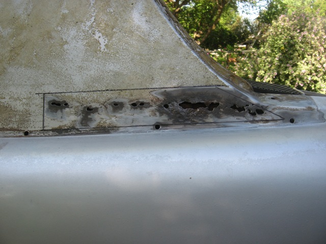
Once the nasty piece was cut out, you can see things were pretty corroded inside. What the picture doesn't show is the foam strips that sit right behind this area. What were the Porsche engineers thinking!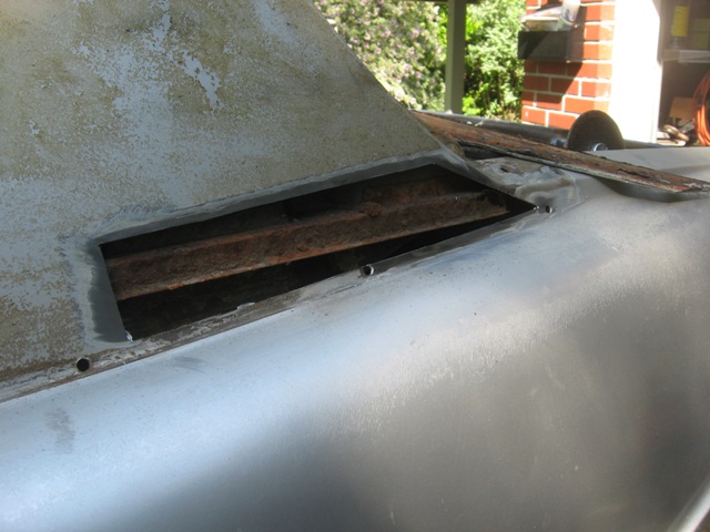
I sandblasted the area as best I could, then did the POR-15 thing on the inside, as well as the back side of the patch. Here is the patch waiting for welding.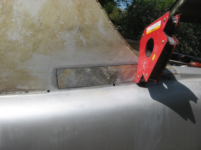
Next up is the patch welded in. To avoid warpage, I made a tack weld, blew compressed air on it until I couldn't feel any heat with my bare hand, then tacked about an inch away, and then repeated about a gazillion times. Here is the finished piece.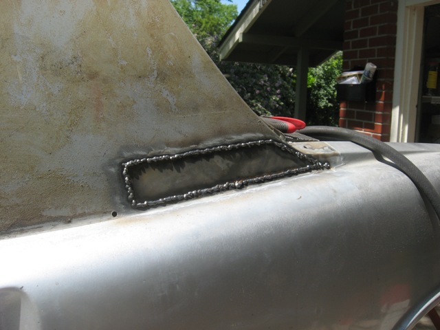
And here it is smoothed down prior to primering.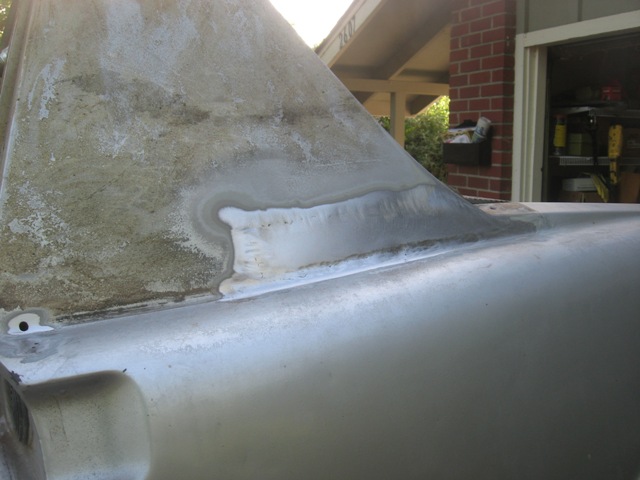
Next up is the area right behind above the driver side door handle...
Posted by: strawman Apr 26 2009, 10:30 PM
I knew there was a mess under the passenger side sail just above the door handle, as it was perforated already. But once I got underneath, I can't believe EVERY 914 is not rusting through in that area. Here is a pic before I started cutting metal.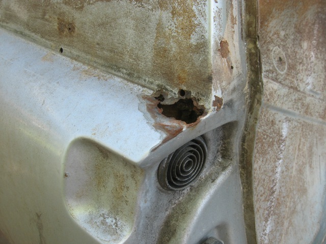
And here is the culprit. Complete nastiness! That chunk of sealant traps moisture against the metal, inviting rust-through.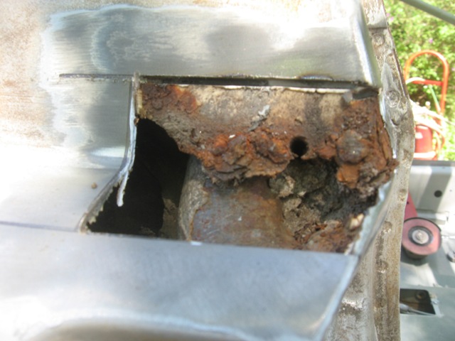
I dug away as much of the sealant as I could reasonably get to and until I found clean metal underneath. Then I POR15-ed the area and the patch, which I cut from Martin Baker's (I can't remember his 'world name!) parts car several months ago. 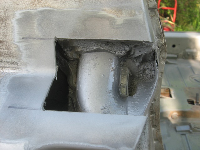
The patch piece was rusted on the back side, too (go figure!), but it was salvageable though thin. I welded it in, using the same tack/cool/tack method described in the post above.
One additional challenge is that the quarter panel seam and door jamb (just above the door vent) is brazed by the factory, then leaded for smoothness. So I had to carefully grind away all the brass and lead to give me a good welding area, but I still got a lot of popping and burn-through trying to join these two pieces of metal. The welds are pretty "snotty," but they'll hold and the snottiness will be hidden by bondo before paint. Here is an after shot prior to primering.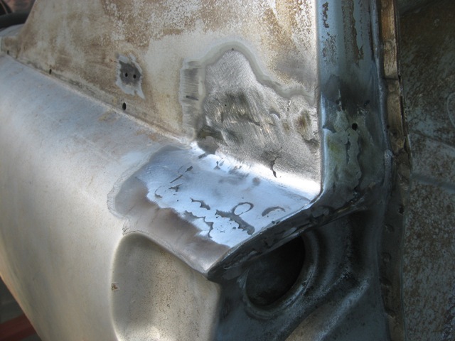
Next up is preparing to re-install the lower passenger side quarter panel that I had to cut out to make the hell hole repairs described earlier. Guess what? Yupper, I found some more rust!
Attached image(s)
Posted by: strawman Apr 26 2009, 10:48 PM
The forward/lower area of the passenger side quarter panel is rusted pretty thin from the backside, but it is salvageable. However, the portion that joins up with the sill plate was gonzo. So I cut a new piece out of 18 gauge, formed it and began the fabrication process while installing the new sill and sill triangles. Here is a pic of the fabricated piece, tacked in place.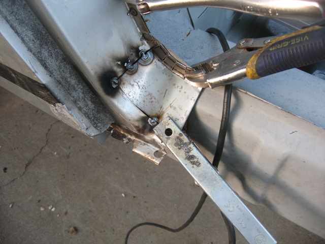
Here is a pic of the triangles that I got from AA. One of them had one of the two "steps" about 1/8" off from the other one, which wouldn't allow the sill to sit tight against it. So I added a 1/8" piece of flat stock (look at the foward triangle).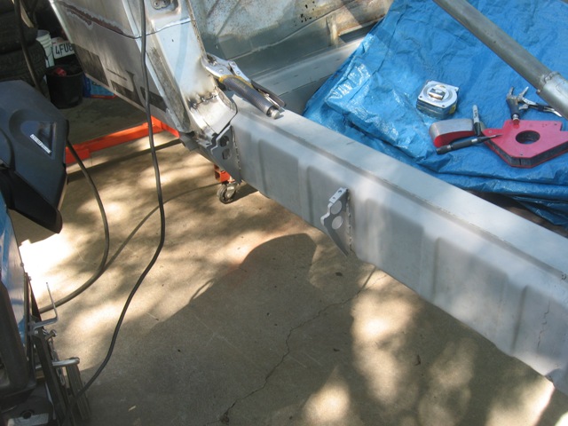
Here is the sill installed, which I also got from AA. Again, I rosette welded a hole, cooled it with compressed air until I couldn't feel any heat with my hand, then moved on to another hole approximately half the length of the sill away. Takes a long time, but that method will hopefully ensure a straight/true tub when I'm done. Fingers crossed!
And here it is ground smooth prior to primer. Again, I would grind a rosette, cool it with air, then move onto another rosette, to avoid warpage.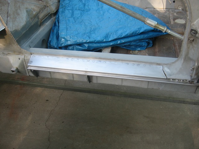
I need to make a couple more small patches on the passenger side sail, fill in the trim holes on both sides, weld in the passenger side lower quarter panel, and then I'll be ready to attack the rust holes in the windshield frame and the frunk seal channel.
During my hip recovery, I was bored silly so I spent many hours scraping away the undercoating on the floor bottom and the wheel wells (gotta love a rotisserie!). I also welded up the 911 parking brake solution that Paul Sayegh demonstrated in Excellence Magazine. Someday soon I'll be ready to weld in the GT flares and begin the turbo Subaru engine/trans fitment...
Posted by: Zaney Apr 27 2009, 09:27 AM
Good to see you up and moving around, Geoff! Here's to a speedy recovery!
Car looks great and is very inspiring to me and others! 
Can't wait to see your magic on the Suby mounting!
Heal up quick!
Nate
Posted by: strawman May 25 2009, 10:01 PM
Been a while since I last posted, but I've been tinkering in the garage...
I'm reversing the intake on my EJ22T engine to permit a bit more room between the throttle body and trunk firewall. It also will permit fewer bends for the intercooler connections.
First off, the 2.0, 2.2 and early 2.5 engines feature the intake-to-head bolt holes in a line, which makes this a relatively straightforward modification. In short, the intake manifold bolts on facing backward or forward, but it ain't quite a bolt-on and walk away affair...
Reversing the intake points the throttle body right at the backside of the alternator. Since I won't be using the air conditioning compressor or power steering pump, I relocated the alternator to where the AC compressor used to sit. Here is a pic of the factory bracket, modified to clear the Idle Air Control solenoid. You can also see where I welded on the alternator mounts and support crossbar.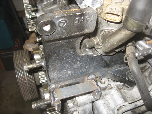
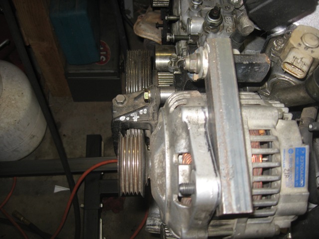
This took a lot of measuring, cutting, more measuring, grinding, more measuring... you get the idea. But it lines up perfectly with the crank pulley. Here is a pic of the alternator as mounted (I still have to fabricate a top mount).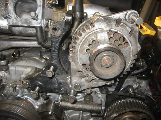
Here is the front and rear views of the engine, not including the wiring harness, coil or fuel rails/injectors.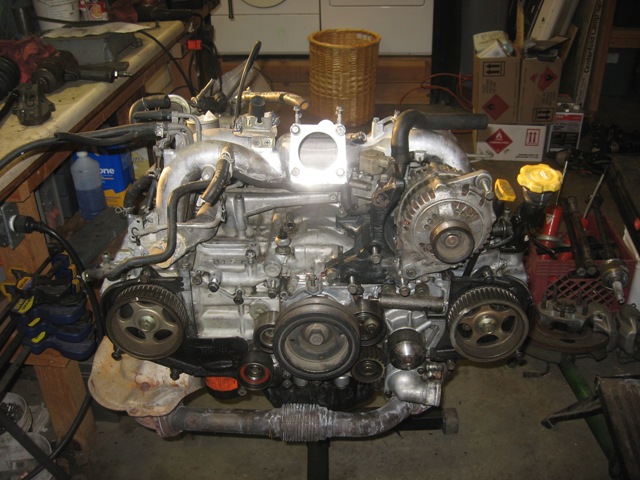
Posted by: strawman May 25 2009, 10:37 PM
I also decided to modify the coolant crossover pipe to remove the rear water heater inlet (I'll pull hot water from near the radiator up front for cabin heat) and to move the two sensors over toward the other cylinder banks to provide clearance for the reversed intake. I probably could've bent the sensor leads down to clear the intake, but I didn't want to stress/damage the sensors. I actually started by modifying the EJ22T turbo coolant pipe by drilling/tapping holes in the factory-supplied bosses, but then realized that the normally-aspirated EJ22 coolant pipe already has the sensors in the correct position. So I picked one up at the local Pick-n-Pull for $10.
The rear water heater inlet is brazed in, so I heated it up slowly and yanked/turned it until it slid out. The hole is the PERFECT size for a 3/8" pipe plug, so I picked up a tap and brass plug from my friendly Ace hardware store. Here is a pic of the tapped hole.
The front water inlet actually bends upward a bit, which puts it relatively close to one of the fuel rail supply lines. I'm sure it would not be a problem to leave it like it is, but I like the idea of nice, cool (non-heated!) fuel. I plan to cut the pipe at its lower point to provide a bit more clearance, and to weld on a "lip" (to help secure the coolant hose). We have an aluminum MIG setup at work, so I'll try my hand at that next weekend -- lucky I now have a spare to practice on! Below you can see the Sharpie line depicting where I'll weld this lip and then cut the pipe.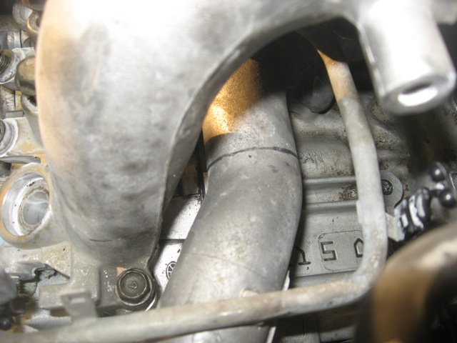
I plan to pick up some steel this week so that I can begin fabricating the engine/transmission mount next weekend.
I've got what I consider to be some good news for those of you considering the Suby trans. I think Porscharu's magic flanges are a great option, but I don't like the idea of using the relatively weak 100mm CVs, as described elsewhere on this site by Paul Sayegh. I also have two sets of 911 axles with 108mm CVs, so I really want the option of using 108mm 911/930 CVs to work out. Some of the 2WD Subaru Legacy and Impreza models came with huge inner "tripod" joints and very large diameter axle shafts. My micrometer says the Subaru axle shaft is large enough in diameter (1.13") to be cut off at the outer joint and machined/splined to use the 28-spline 930 CV at the wheel end. I'll need to borrow my friend's non-Chinese built calipers to verify. At the very least, the diameter is large enough to have the Suby inner and 911 outer axle shaft ends welded together. If that option doesn't pan out, EMPI sells 930 CVs and custom-length 28-spline axle shafts that can be used as blanks. EMPI also lists the Suby 2WD inner joint as a separate part on their website, so I'll pick up a pair of those for my eventual Frankenaxles.
More to come...
Posted by: strawman Jun 3 2009, 11:36 PM
Still been plugging away...
Below are some pics of the shortened water pipe, with the welded lip filed down. That was a major PITA, but the lip should help keep the coolant inlet hose from slipping off. Basically, I welded a "ring" around the water pipe, cut off the pipe on the aft side of the "ring," and then shaped the lip with a file. Probably more than needed, since this pipe is in "suction" and likely wouldn't slip off with a hose clamp... but I have access to an aluminum MIG setup, and I'll sleep better at night knowing the hose can't slip off.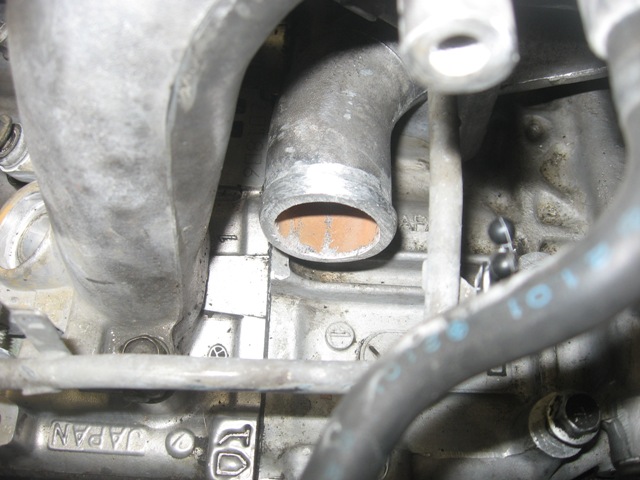
I'm also attaching a couple of pics of the final (almost) alternator setup. You can see the 0.70" spacers I spun on the lathe -- though they're still raw/unfinished -- as well as the upper mount. I still need to clean up the welds of the upper mount, trim the angle iron "connector," polish the spacers, and then paint the whole shootin' match. The belt now lines up perfectly, though I'll need to use a 3-rib belt to match the tensioner; the alternator and outer crank pulley are 4-rib.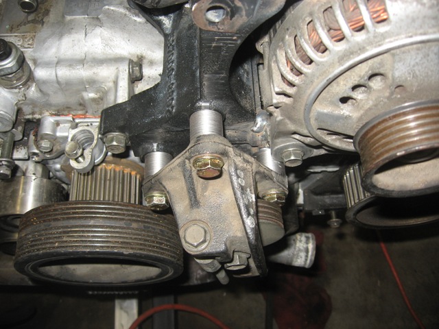
Posted by: strawman Jun 3 2009, 11:55 PM
Tonite I also welded on the lower passenger side quarter panel that I had to cut off to make the hellhole repairs. The factory panel had some rust "thinning/swiss-cheesing" that required some careful repairs. First off, I sand-blasted the entire backside of the thing, as well as the frontside areas that showed rust bubbles. Then I welded in a couple of very small patches, and carefully tacked in some plugs where the metal was particular thin (read that, where light shined through!).
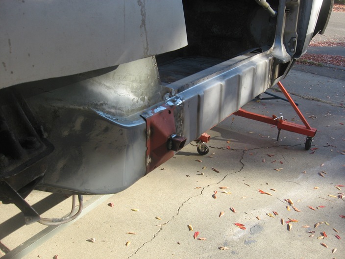
Here is a pic of the lower piece welded in.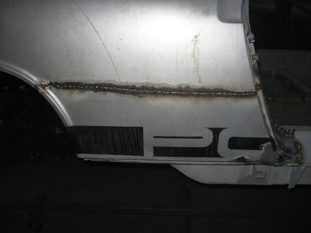
The most difficult part was replacing the compound bend at the forward/lower part that connects with the sill plate (i.e., below the lower rear part of the passenger side door). But I think it came out looking pretty good. I welded that piece to the factory piece on my bench, and ground down the topside welds prior to connecting it. Below is a pic of that repaired area, prior to trimming and smoothing. As you can see, I also need to fill in a couple of spotweld cutter holes with small round patches.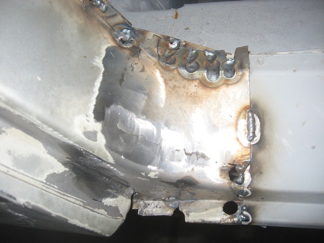
Here is a pic looking back, with a shot of my trusty/cheapo Craigslist welder poking its head in. It is a Clarke EN130 110volt unit using EASYGRIND 0.023" wire and 75% argon / 25% CO2 gas...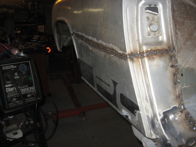
This takes quite a while to avoid imparting too much heat -- weld a spot, blow it cold with compressed air until your bare hand feels no heat, move over 5-6" and weld another spot, and repeat a gazillion times. I still need to grind down the welds and take some pics.
Posted by: Gint Jun 4 2009, 07:34 AM
Awesome work!
What's your opinion of the weld through primer?
Posted by: strawman Jun 4 2009, 06:42 PM
Awesome work!
What's your opinion of the weld through primer?
It works fine, but you should scrape a small section clean (I used a center punch) to strike the MIG arc. Once the arc begins, you can easily weld through it.
Posted by: al weidman Jun 5 2009, 12:34 AM
Geoff, I have tried to find the "easy-grind" wire in Chico and Oroville and they do not carry it. Where do you get yours? I am thinking of doing my rusto outside also. Does the blue tarp keep it dry through the winter? Great job, maybe you could have our Sacramento group over for a visit some Sunday morning. We could run it by Rob. Al.
Posted by: strawman Jun 5 2009, 12:42 PM
Geoff, I have tried to find the "easy-grind" wire in Chico and Oroville and they do not carry it. Where do you get yours? I am thinking of doing my rusto outside also. Does the blue tarp keep it dry through the winter? Great job, maybe you could have our Sacramento group over for a visit some Sunday morning. We could run it by Rob. Al.
Hi Al --
I couldn't find Easy-Grind locally either, so I bought a 10 lb. roll online and had it shipped. Google it; shouldn't be too hard to find.
I'd be up for a Sac group meeting, although my garage will pale in comparison to Paul's... any my car is far from perfect. I'm bummed, since I'll miss the next meeting and won't be able to see Paul's setup firsthand.
I put the blue tarp on it when weather is wet/rainy. It is pretty dry in these parts, so I don't cover it all the time and I don't get a lot of flash rust. I try to primer/seal panels as I go to protect the metal, too.
When I'm done with panel replacement work in the coming months, I'll have a rotisserie available for cheap. I think I've got about $100 in it and would be willing to let it go cheap. It breaks down easily and could fit in the back of a pickup or large wagon. Let me know if you're interested.
Geoff
Posted by: charliew Jun 5 2009, 02:13 PM
I have never came across a brazed tube in a aluminum casting. On my 02 wrx coolant crossover the tube is pressed in with a sealant it seems. Also the turbo version crossovers are bigger to carry more coolant than the na versions. Grimspeed and others carry a spacer that is to prevent the engine heat from moving into the intake manifold from the head, I think it's a phoenolic material. You can get them in 7mm or maybe 13mm thicknesses. On my son's sti they work great. With the thicker ones you will need longer bolts.
The only way I can get easygrind is either buy a case at 55.00 a roll or for just one 10lb roll it's 66.00 locally.
Posted by: strawman Jun 5 2009, 06:09 PM
I have never came across a brazed tube in a aluminum casting. On my 02 wrx coolant crossover the tube is pressed in with a sealant it seems. Also the turbo version crossovers are bigger to carry more coolant than the na versions. Grimspeed and others carry a spacer that is to prevent the engine heat from moving into the intake manifold from the head, I think it's a phoenolic material. You can get them in 7mm or maybe 13mm thicknesses. On my son's sti they work great. With the thicker ones you will need longer bolts.
The only way I can get easygrind is either buy a case at 55.00 a roll or for just one 10lb roll it's 66.00 locally.
Hi Charlie --
Your suggestion that the turbo'd coolant crossover pipes might be true for EJ20 or the 2.5 engines, but it certainly is not true for the EJ22T or EJ22 engine -- the crossover is virtually the same, only with different bosses drilled/tapped for placement of the sensors. At least my naked eye suggests it. Guess I'll have to check it out with my calipers.
You may be right that the heater hose "extension" is pressed in with a sealant -- but I couldn't get it out without heat. That is why I presumed it was brazed...
I have looked at the Grimspeed spacers, and I might end up using them. I like the idea of a cooler intake charge!
Which engine are you using in your Suby conversion? Is your engine ready to go?
Geoff
Posted by: charliew Jun 6 2009, 04:27 PM
You can put your hand on my sons sti after driving it and just get out and open the hood and touch the intake with the spacers.
I have some 2.5 na coolant crossovers and the wrx and sti is wider that is what I was going by. I'm pretty sure the 22t only made 160hp.
Well, I sorta have a motor, I have a 02 wrx motor and tranny with 5k on it that I have had a year or so. I went to kansas and bought the most of a front clip out of a wrx that a older man had bought in 02 but passed away before he could use it. It was on nasioc classifieds. I originally got it to put in a dunebuggy. I decided the buggy would be hard to do a radiator and still look nice. while I was getting the motor ready I built a large 8qt short oil pan and a modified ss header that is shorter and bought the outfront alt bracket and belt. I also have a 96 2.0 tt motor and tranny and all the tt stuff that came with it. I also have a 2.5 sti shortblock and a 2.0 closed deck shortblock And many sets of heads that I have found over the past few years. My son hotrods a sti and I have fabbed him a bigger oilpan and some other stuff for his car. A true cold air intake and a enclosed shroud for his front ic, I have also redone his ss ic piping to have fewer sharp turns.
We took the original motor out of his sti at 40k and put in a built motor with a lot of stuff, bigger cams a bigger turbo, ported heads, bigger oilpump, a external oil bypass to adjust oil pressure and modified tumble generator valves on the intake. He is a me and likes to study this stuff and I like to fab hotrod stuff.
I've got all of his old parts that are left over from his upgrades. He will be the one programming the wrx ecu for me in the 914 with open source romraider. I will probably start with the wrx motor but soon will be making a 2.5 with wrx heads and sti cams with a sti turbo. If he goes to a 35r from the 30r turbo I guess I might try that. The 30r makes a reliable 26lbs of boost on his 2.5. We haven't dynoed his car but the hp is around 400-425 awdhp by his 1/4 mile speed and times but he is really tuning it conservitively on 93 pump gas. He is really not a dragracer.
I have put a bremar conversion on the 96 legacy tranny and have bought two obx lsd's to put in both trannys. The 96 is a 4:44 I think and the wrx tranny is a 3:90. Really the 3:90 is probably the best in the 914. I also have two sets of porscharu's flanges for the trannys. I found some new 17 inch boxter wheels and tires from a porsche dealer in Balitmore for 825 shipped, the tires are 25 inches tall. The tires are 8 in the front and 10 in the rear. I will make a cable shifter but I really want to build a sequential shifter. Suby drivers are notorious for getting in the wrong gear on down shifts and breaking ring lands on the pistons and causing other things like spun rod bearings. I will probably use a air to water ic as I think in the 914 that will be the most efficient. I've gotten the 911 front and rear stuff including the emerg. brake stuff and also the aluminum brembos from the alfa romeo milano to use front and rear. I've got the wrx rad. but also found a new custom 1 inch tube two row alum. rad really cheap on ebay. It was for a v8 ford in a toyota truck but it's the perfect size for the 914, 35.00. It also has 1.250 inlet and outlets.
My only problem is the damn house projects that keep piling up. But also the other toys in the shop. I have also been helping my oldest son restore his 72 super beetle I took away from him in 86.
Posted by: strawman Jun 7 2009, 08:49 PM
You can put your hand on my sons sti after driving it and just get out and open the hood and touch the intake with the spacers.
I have some 2.5 na coolant crossovers and the wrx and sti is wider that is what I was going by. I'm pretty sure the 22t only made 160hp.
Hi Charlie --
I just ordered a set of the Grimmspeed phenolic spacers... one of those "while I'm in there" purchases.
My EJ22T has a TD05H-16G turbo, topmount charge air intercooler, manual boost control and fuel cut defenser. So I'm hoping to get ~200 hp from that engine, based on "conjecture" on the LegacyCentral website. No matter -- I'm treating that engine as a "prove it can be done" situation, and will replace it with an STI engine down the road.
Good luck with your project!
Posted by: strawman Jun 7 2009, 08:55 PM
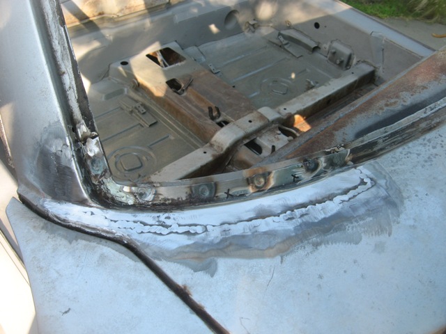
Had a chance to spend some more quality time with my project this weekend. First off, I received my pre-bent inner suspension console reinforcement kit from Tangerine Racing on Friday, so I welded it in that evening. It fit without any drama; here is a pic of the passenger side: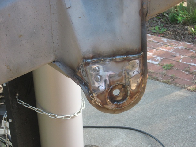
I also started to make some firewall repairs due to rust-through and to finally patch up the hell-hole repair.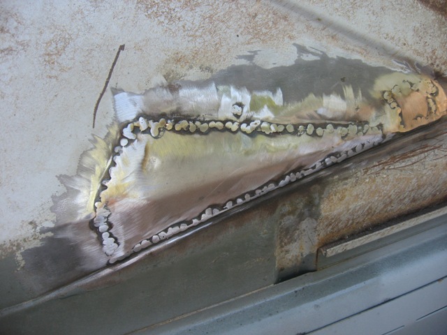
Next up are repairs to the windshield...
Posted by: biosurfer1 Jun 7 2009, 08:59 PM
Get anything good at the swap meet?
Posted by: strawman Jun 7 2009, 09:10 PM
Both lower corners of my windshield are crusty. I picked up driver and passenger side fender/cowl cuts from Derrick (can't remember his 914World name) in Palo Alto. While they had some rust in them, they were in far better shape than my car's.
Here is a pic of the passenger side lower corner: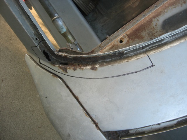
It took about 90 minutes to carefully cut out the passenger side piece I needed from the donor fender/cowl. It took every tool in my box (air body saw, jigsaw, sawzall, 1/8" cutting wheel on a die grinder, carbide burrs in a die grinder, etc.), and a ton of patience! Here is that piece prior to being fully cleaned up.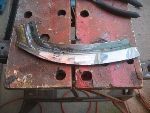
Here is the cut-out, followed by the piece rough grinded (I forgot to take a pic of the piece welded-in / pre-grind). I used my friend's spot-welder to tack up the piece along the seam, and my trusty MIG to complete the butt-welds. The lead used by the factory at the cowl/fender seam caused a lot of popping, and the lead flew when I cooled each tack weld with compressed air...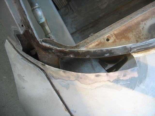
I'll tackle the driver side lower windshield later this week.
All told, I spent about 15 hours this Fri-Sun making these repairs. While the progress is seemingly slow on these little projects, I am heartened that they're done. I can't wait to begin the motor/trans mounting effort, as well as the fender flares project -- but I still have some more rust to deal with.
I went to the Parts Heaven swap meet this morning, and picked up a clean targa top, some spare trailing arms, rear non-defrost window and a rough fiberglass front bumper. There were some incredible cars there, as well as some good deals.
Posted by: strawman Jun 7 2009, 09:13 PM
Get anything good at the swap meet?
As stated above (you're quick with your posts!), I got a few things. I forgot to mention that I picked up a set of sway bar reinforcements, as well as new engine lid weld-on mounts.
The bummer is that I just missed out on a fully-adjustable Weltmeister front sway bar for $125. I literally talked to the guy, went to my car to pick up my gloves and when I got back two minutes later, a guy was handing him cash. D'oh!
Did you go? Get anything interesting?
Posted by: biosurfer1 Jun 7 2009, 09:31 PM
I couldn't make it but Justin (didn't he go with you?) got my a center console with gauges and retractable seat belts.
Posted by: charliew Jun 8 2009, 09:11 AM
Strawman I don't know how much studying you've done on the waic stuff but the aussie mag autospeed has some pretty good stuff. Here's one article on the parts for making your own and where to find them if you are not using a kit.
I don't know which year awic suby cooler you have but one they mention is good for 210kw. I'm not good with metric but the conversion is about 1.35hp+1.0kw. I would guess on my simple estimation thats about 260hp
Course then water and or meth injection will cover even more hp increase. They cover that also.
http://autospeed.com/A_107760/cms/article.html
Posted by: strawman Jul 20 2009, 11:44 PM
Over the past few weeks, I've been cleaning up and working on the engine, getting it ready to shoehorn in. Suby engines are cheap (especially if you buy a whole parts car and sell off the leftovers!), but it ain't so cheap to buy gaskets and ancillary parts. I replaced all o-rings and assorted gaskets, the water pump, belts and hoses, and had the injectors cleaned/blueprinted by Witchunter. All told, this effort required about $400, but it should ensure a leak-free engine.
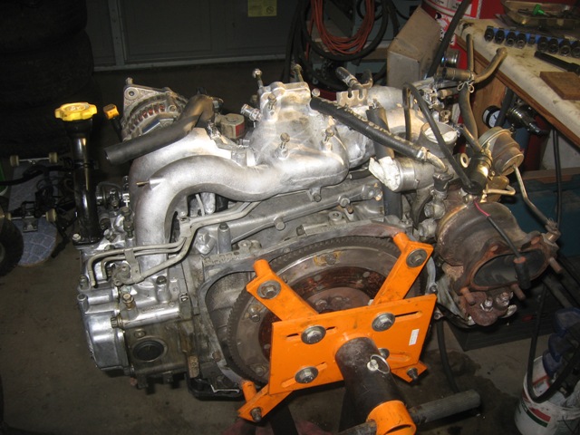
I picked up some scrap metal and an electric hoist on Craigslist to build a gantry, as presented below. It is ugly, but it works great for lifting up the engine up to the height of the rotisserie'd tub. However, the rear firewall gets in the way to effectively position the engine exactly where it needs to be, so I built a couple of sawhorses with adjustable-height mechanisms to get the engine where it needs to be. In this scenario, I set the engine at the desired angle and then move the rotisserie'd car where it needs to be. Take a look at the pics: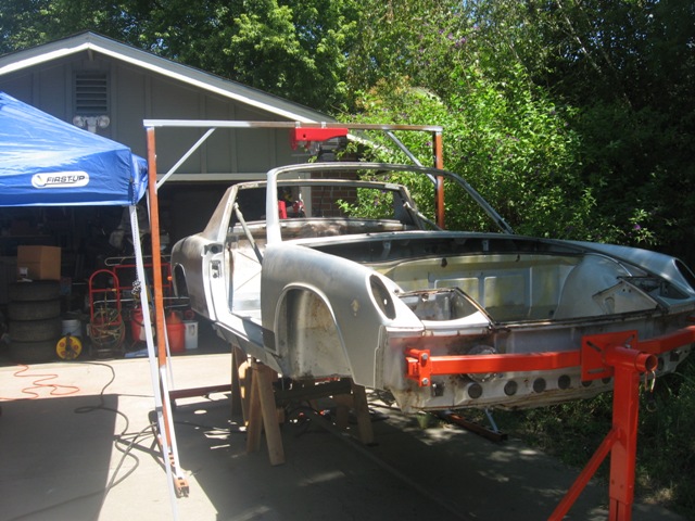
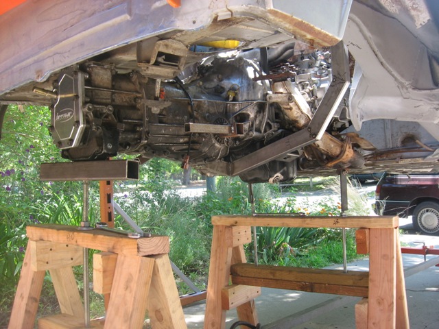
Posted by: strawman Jul 21 2009, 12:17 AM
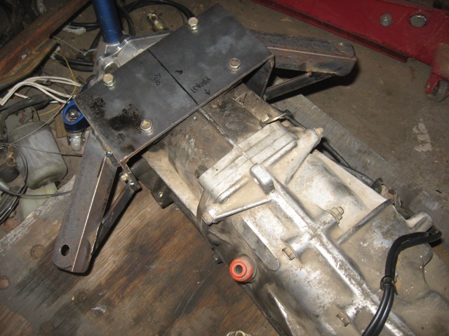
Next up is the engine cradle, built out of 1"x2"x 0.120" wall tubing. This bolts directly to the stock Subaru motor mounts, and barely clears the turbo up-pipe. I built it so that it will be the lowest point and can provide some oil pan protection (although the previous pics don't show it, I will ultimately shorten the pan about 2"). Here is a pic: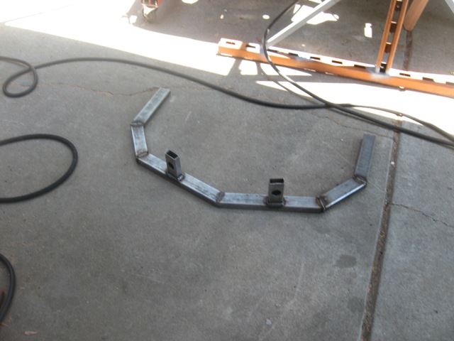
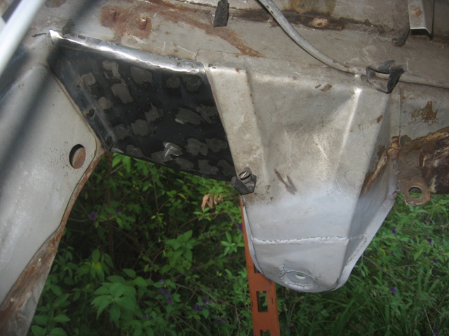
The cradle will bolt to mounting ears that I'll weld on gussets that I've installed on the upper longs (see below). I believe the cradle will help tie together the rearward portions of the longs, and the gussets that I've fabricated will tie in the lower portion of the GT kit and the inner potion of the longs. Below are a couple pictures of the gussets that I fabricated out of 16 ga. steel -- prior to welding and then after rosette welds / grinding smooth.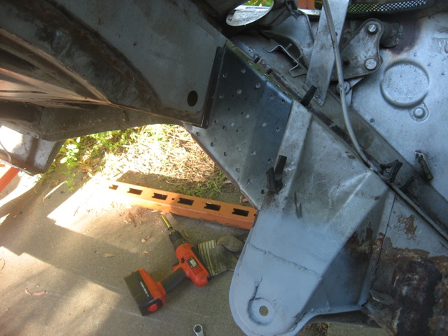
Here is the clearance and mock-up of the transaxle:
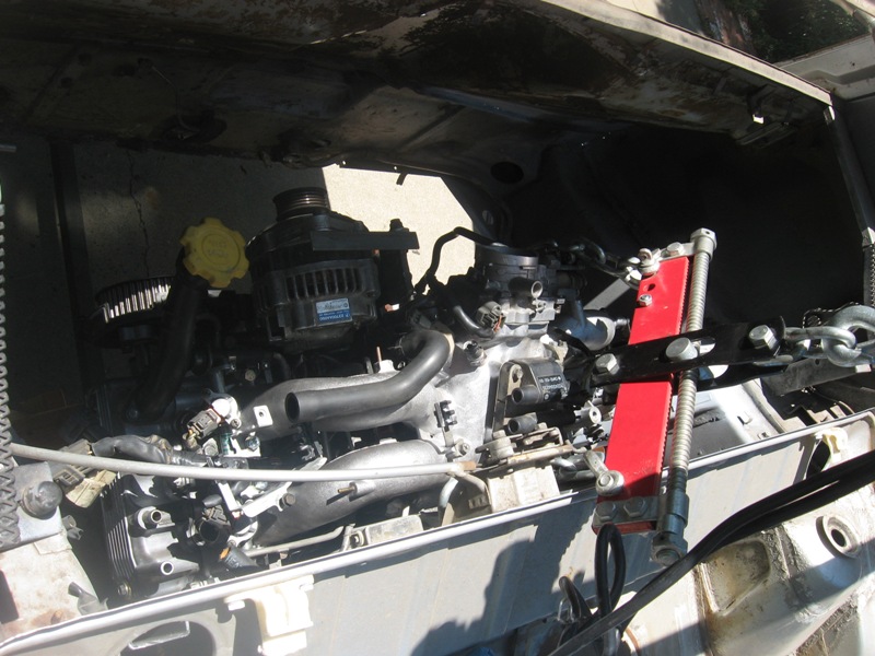
Finally, here is a pic of the engine bay, showing where the turbo will be mounted. Obviously, I need to cut out a portion of the rear firewall/trunk floor, and construct a box for the turbo. I also need to box in clearance for the hydraulically-controlled clutch and possibly the starter. With regard to the starter, I'm still investigating the gear-reduction WRX starter, which is "clocked" such that it might fit under the stock rear firewall. More to come on that. 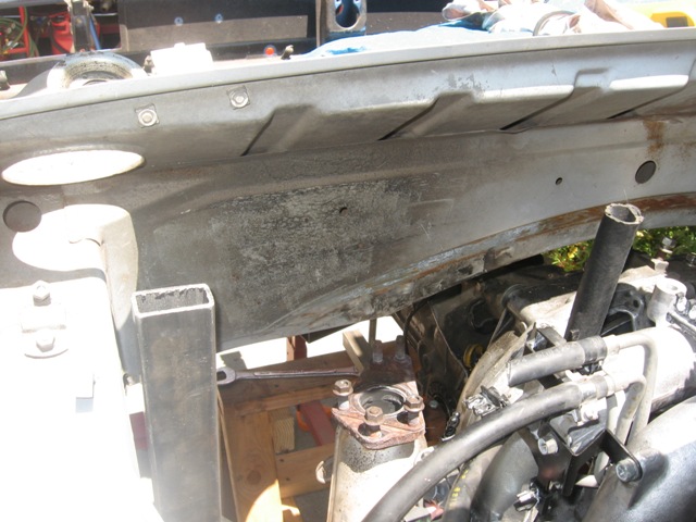
Next up is completing the seam welding of the driver-side gusset, fabricating/welding the passenger side long gusset, completion of the mounting ears for long-to-cradle, and completion of the cradle. Then I'll fabricate the transaxle mount. I hope to tie the cradle to the transaxle mount to keep the tail of my teener connected to middle of the car.
In terms of fore-aft location of the engine/trans, I tried to keep the engine located as far back as possible to keep a slight rearward weight bias and to line up the output flange-to-hubs to the extent possible. According to my measurements, the angle is ~0.50" off (output flange is slightly forward of the hub) -- which is less than the angle of the stock Subaru output-to-hub setup (~1.0" offset).
Stay tuned...
Posted by: strawman Aug 24 2009, 01:43 PM
I haven't posted in a while, but I've been busy.
I completed the engine mount system, as well as the transmission mount system. My wife-n-daughter were away this weekend and they took the digital camera, so I was unable to take any pics of my recent progress. I'll snap some shots in the coming days and post them here.
But the big news is that I sold my racing karts on Sunday to bring some more money to the project. I just ordered an OBX planetary limited slip for my Suby trans. I'll try to chronicle that build soon after the unit arrives. I also just got off the phone with Chuck at Elephant Racing Products and bought the following items:
1. Polybronze suspension bushings, front and rear
2. Tarett front sway bar and weld-on A-arm mounts
3. Front monoball camber plates
4. Balljoint mount kits.
I plan to drive down to San Jose next week to pick up the items, and to have him check out my Bilstein Sport strut inserts. Elephant now rebuilds & revalves Bilstein struts ($250/pair; Bilstein in Poway only charges $150/pair).
I plan on staying with the stock 911 18.8mm torsion bars up front for now, although he is suggesting that the Bilstein Sports are "too much" for the stock front 911 torsions -- especially in a 914. I'm a little reluctant to move up to a larger set of front torsions until I have a chance to drive the car. Anyone have some advice for me, both in terms of the torsion bars and strut inserts (I have 911 Bilstein strut housings)? Maybe it would be best to finish assembling the car, corner weight it and then send the strut inserts in for a rebuild/revalve? The car will be used primarily for spirited mountain road driving, occasional autocrosses and some HPDE track events.
Geoff
Posted by: strawman Sep 3 2009, 10:56 PM
Here are some pics of the suspension stuff I picked up from Elephant Racing Products yesterday. Chuck is a really nice and knowledgeable guy, and I had fun looking around his shop in Santa Clara. Like many hot rod shops, it is pretty unassuming from the outside, and I drove by it twice looking for a great big neon sign...
I also ordered some Bilstein (pronounced Bil-Stine, I now know) rear shocks, front Bilstein linear bushings, and front strut wiper seals that ERP will ship in the coming days.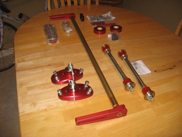
Besides the stuff listed in the post above, I also bought new bearing seats for my Bilstein strut housings. I already have new wheel bearings and seals for when I put the front end back together.
This weekend I plan to weld in stiffening tubes in the spare trailing arms I have, similar to Eric Shea's modifications (the wrap-around stiffening kits really make the arms really HEAVY, I've found!). I also plan to weld on the rear trailing arm e-brake pivots, raise the spindles 19mm on the front Bilstein strut housings, weld on the A-arm sway bar mounts, sandblast all suspension pieces, and I hope to find time to take the lot to a powder coating firm in Sacramento next week.
Time permitting, I'll also tear into the Suby trans this weekend to install the OBX limited slip. I'll take pics as I go for anyone interested in the guts of these boxes. I've never been inside this box before, but I've had experience setting up ring-n-pinions when I was into four-wheeling so I'm not too escairt.
Below is a pic of the Suby trans mount, as bolted to the stock 914 location using 911 engine mounts. I've also attached a pic of the trans mount bolted on the Suby trans. This mount will provide a nice "canvas" for mounting the cable shifting system...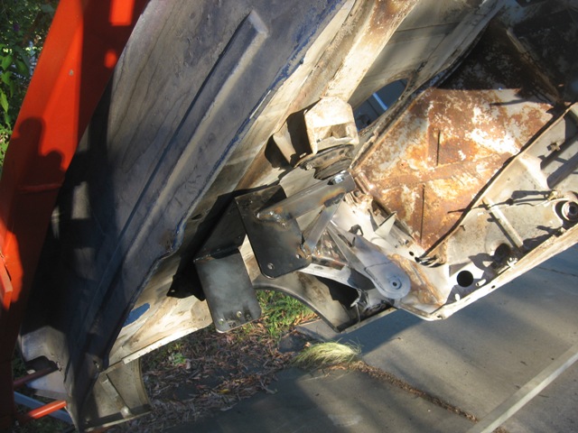
Posted by: strawman Sep 12 2009, 10:44 PM
A little update...
I welded on the front sway bar tabs on the A-arms, removed the ball joints, burned out the factory rubber bushings and sandblasted the arms. I hope to get them to the powdercoater this week so that I can install the new hardware depicted in an earlier post. No pics, as this isn't exactly rocket science.
Below is a pic of the raised spindles on my 911 Bilstein struts. After searching the Pelican site and a few Porsche mod shop websites, I decided to raise the spindles a total of 30mm (instead of 19mm as indicated in an earlier post). It took a lot of time grinding out the factory rosette weld, measure depth, grind more and measure again until I was sure I ground out enough without bunging up the strut tube. Even still, it stressed the 55-ton press I have access to pop it free and keep it moving to the desired height. 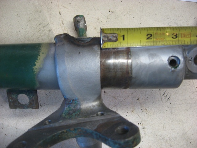
I plan to weld on a lower "arm" onto the strut tube just above the ball joint roll-pin hole so that I can run a long bolt between the factory arm (drilled out to 14mm) and this new arm, with spacers to get the optimal tie-rod height to reduce bumpsteer. Stay tuned for pics of that completed mod as soon as I procure suitable bolts and spin spacers on the lathe in the coming weeks.
The rear Bilstein dampers arrived this week, but no pics are necessary. I also tore apart the Suby trans, and everything looks good (it shifted fine when removed). Even so, I ordered new bearings throughout and plan to assemble it this week with the OBX limited slip. Stay tuned for pics of that, too.
Posted by: strawman Sep 12 2009, 11:08 PM
Okay, so I just got another cocktail, and thought I'd take the time to add some more details of the trans teardown.
First up is a pic of the trans on my workbench, with the rear and mid case removed. As noted, you can see the Bremar coupler. You can also see one of the two trans side covers that provide the side-side adjustment of the differential/ring gear to get a good pinion / ring gear pattern.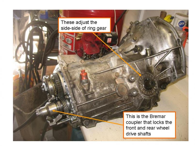
Here is a pic of the mid case draining out the nasty-smelling gear oil. As part of the Bremar FWD conversion, you toss the rear case & guts, which originally housed the center differential. The shift rod is also shown in this pic.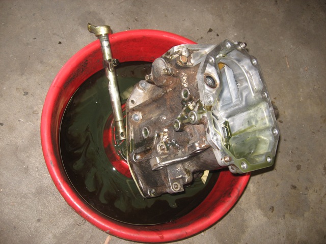
Next is a pic of the guts of the trans.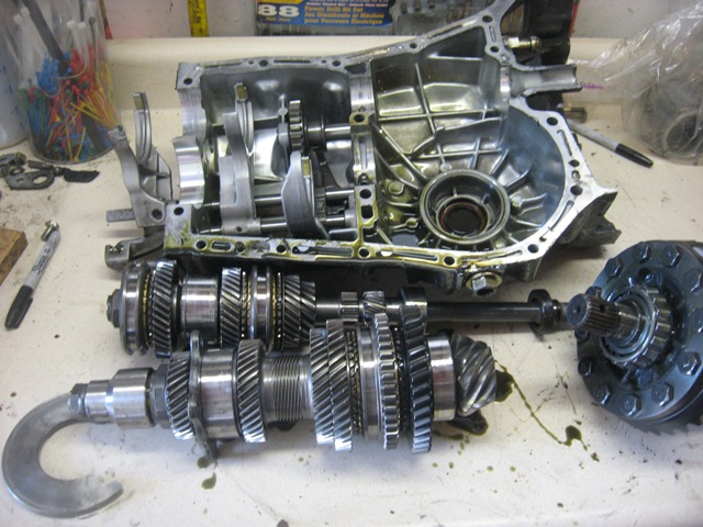
Here is a side-by-side of the factory diff and the OBX limited slip.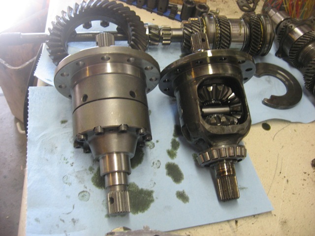
Posted by: strawman Sep 12 2009, 11:12 PM
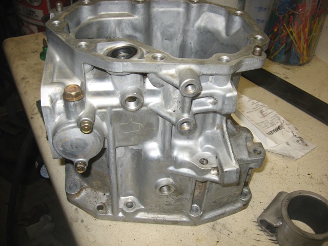
And here are a couple of pics of the main and mid trans cases all cleaned up. Just waiting for the new seals, o-rings and bearings that will hopefully arrive this week.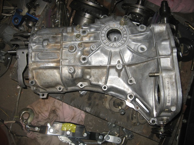
Posted by: charliew Sep 17 2009, 11:14 PM
I like the engine cradle it's similiar to Tony's. Looks good.
Are you going to expect the pinion depth to remain the same after you replace the bearings on the pinion shaft? Did you happen to check the backlash on the original setup? Just curious as I am going to put 05 legacy internals in a 02 wrx case with the obx and I saw where suby has a flat plate tool to set pinion depth. It looks like one could be made using a known good setup and using it on later rebuilds. It uses two pins that register in the case bolts and butts against the end of the pinion it seems from pictures I've seen. Since you are not changing the ring and pinion you might be ok just setting the backlash as that seems to be your game plan. Thats seems to be what the guys on nasioc are doing. I guess thats the early tranny from the 93 instead of the 99 tranny you mentioned at the first? It looks like the tt one I have. Is it a 4:11 or 4:44 fd? I read somewhere that the pre 99 tranny were different but the 96 I have looks a lot like the 02 wrx and the 05 legacy other than the clutch arm and the axle stubs missing on the 05 and the removable plate on top of the center case of the early tranny.
While you are in there look how much room there is with the center diff out. I'm thinking the cables for the shifter could be internal and that would clean up the rear of the car under the bottom.
Posted by: strawman Sep 18 2009, 07:33 PM
<snip>
... Since you are not changing the ring and pinion you might be ok just setting the backlash as that seems to be your game plan. Thats seems to be what the guys on nasioc are doing.
Hi Charlie,
Yup, I'm only planning to set the backlash and test to make sure I've got a good gear pattern.
I guess thats the early tranny from the 93 instead of the 99 tranny you mentioned at the first? It looks like the tt one I have. Is it a 4:11 or 4:44 fd? I read somewhere that the pre 99 tranny were different but the 96 I have looks a lot like the 02 wrx and the 05 legacy other than the clutch arm and the axle stubs missing on the 05 and the removable plate on top of the center case of the early tranny.
No, I've confirmed from the part number that it is out of a 1998 Forester, with the 4.11 ratio. It has a transmission code of TY753VJ1AA.
While you are in there look how much room there is with the center diff out. I'm thinking the cables for the shifter could be internal and that would clean up the rear of the car under the bottom.
I'm not sure that would be possible; where would the cables enter the case? And how would you rotate the rod with the cables inside the case? I think cable shifting at the back of the trans should be fine...
Geoff
Posted by: strawman Sep 21 2009, 02:16 PM
Are you going to expect the pinion depth to remain the same after you replace the bearings on the pinion shaft?
Hi Charlie --
I neglected to state in my previous posting that I am not replacing the bearings on the pinion shaft -- only those of the mainshaft and differential bearings.
Finished up the trans reassembly this weekend, and began mocking up the cable shifter setup. I'll try to post pics later today or tomorrow.
Geoff
Posted by: charliew Sep 22 2009, 07:54 AM
I'm sorry Geoff, by early I meant the 99 and earlier trannys, I think they are the only ones with the inspection cover on top of the gear case.
The 4:11 should give a little relief to the gears regarding the torque applied to them. Also it will have a pretty short low, I'm anxious to see how you like it.
I really think the 3:90 is probably the best unless a 3:54 is available because the car is so light, but tire dia could also be used to adjust the fd some be. Of course that puts much more strain on the gears and shafts.
The rotational motion would be the same inside the case as the outside but might require more leverage at the shifter as the internal arm inside the case would need to be so short. The cables would need to enter higher than the fluid level, I would think.
Posted by: strawman Sep 23 2009, 11:12 PM
So I finished up the installation of the OBX limited slip differential, including many new bearings (mainshaft and diff bearings) and all new seals/o-rings. The LSD was $412 delivered, and the bearings/seals was another $200.
First pic is of the guts, including the anaerobic gasket maker.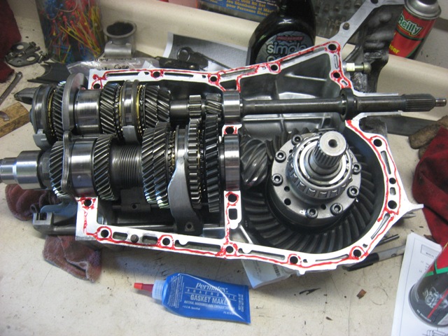
Next up is a pic of the main case halves bolted and torqued, as well as the "mid" case bolted and torqued. Note that the "rear" case is eliminated with the Bremar 2wd kit...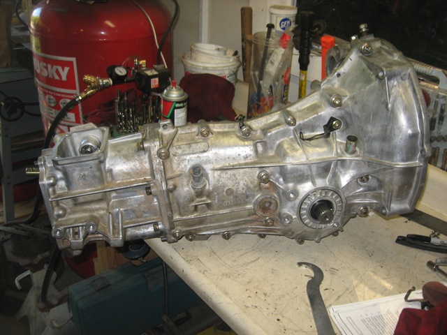
I then bolted up the trans to an engine stand to begin setting the backlash. As you can see in the photo below, you need to weight the differential (in this case, that is a 911 front brake rotor wired to the driver-side axle stub). This essentially pulls the ring gear away from the pinion gear. Note that I didn't replace the pinion bearings, because they looked to be in great shape and I didn't want to mess with the pinion depth... hopefully that decision won't end up biting me in the ass. The passenger side adjuster is installed without its o-ring so that you can easily turn that side's adjuster. 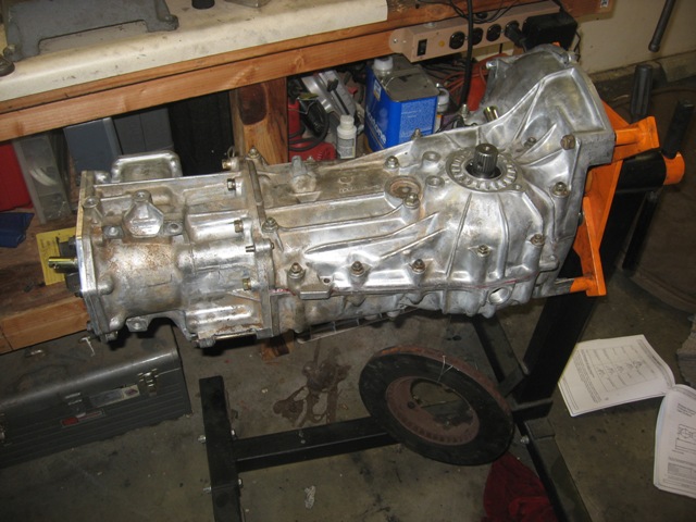
You then screw in the driver side adjuster from below until you make contact between the ring gear and the pinion gear. Then you adjust the passenger side in until you preload the case bearings. Next you back off the driver side 1.5 notches (see the "teeth" on the adjuster?), temporarily tighten the passenger side adjuster 1.5 notches, mark that location, back off the passenger side adjuster enough to install the o-ring, and then tighten the passenger side back to its marked spot. Finally, you secure the adjusters using the locks (I didn't take a pic of those, but they're bolted in the threaded hole that is slightly obscured by the bicycle lock-ring tool in the pic below.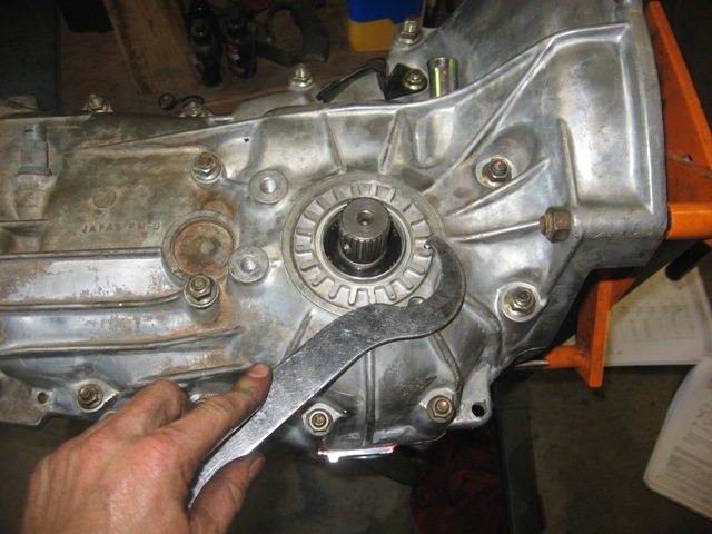
Posted by: strawman Sep 23 2009, 11:32 PM
Now that the transmission is ready to go, I started on the mock up of the shifter and cables. I am using an AW11 model Toyota MR2 ('85 to '89) shifter that I picked up at a local Pick-n-Pull for ~$25, including the shifter cables. Here is a pic of the shifter on a module that I welded up and bolted to the top of the transmission.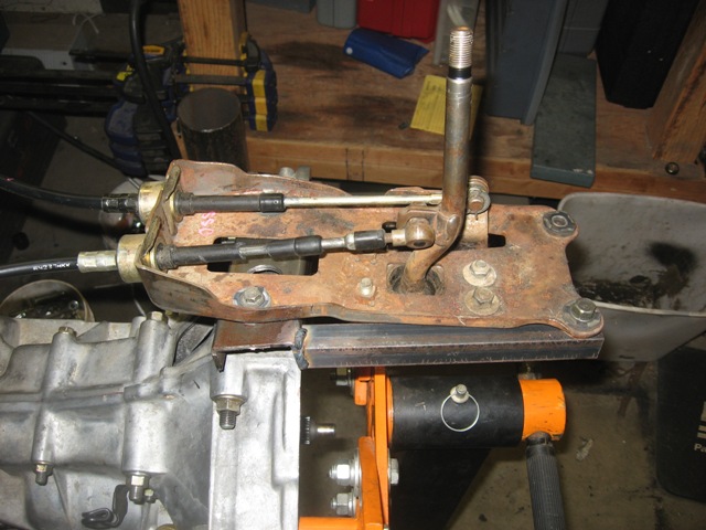
Next up are a couple of pics of the business end of the shifting mechanism. Obviously this is a mickey-mouse mock-up -- but I wanted to see how tall the shifter upright needed to be, and where to locate the left-right stand-off. I clamped the upright to the shift-rod connector using Vise-Grips until I got the height of the upright correct, then tack-welded it. It shifts great, despite the extreme angle of the fore-aft cable. Custom cables will take out the these kinks...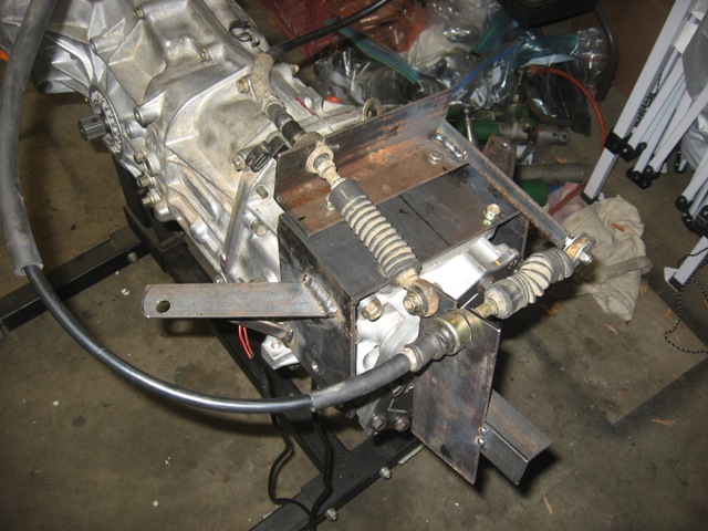
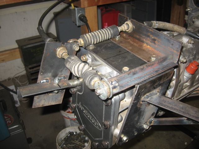
It should be noted that the movement of the shift rod fore-aft and side-side is very acute. Below is a series of four pictures that depicts the side-side (note the rubber boot is scrunched when you compare the top two pics when moving the shifter from the 1-2 gate to the 5-R gate) and fore-aft (note the differing distances of the upright in comparison to the rear of the trans when the shifter is moved from 1st to 2nd).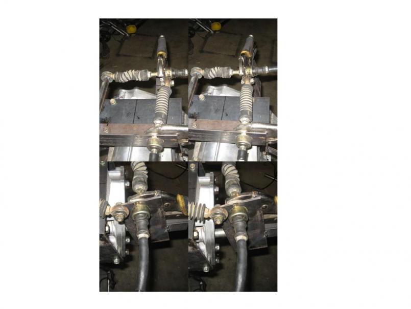
I'll make the whole mechanism much more pretty, and weld the stand-off to the trans-to-body mount. I'll probably have to make up a new module for the shifter, too so that I can accommodate the length of the cables, which will use rod ends at each end. Stay tuned!
Posted by: strawman Oct 22 2009, 01:12 AM
I finally got around to finishing the rear trunk replacement, including cleaning up the welds, ospho-ing the bare metal, and epoxy primering those prepped areas. While I had the spray gun out, I also epoxy primered the GT chassis kit, the passenger side suspension console, the Tangerine Racing suspension ear reinforcements and the engine mounts. Finally, I sandblasted the front 911 A-arms and epoxy primered 'em. I will take pics and post them this weekend.
I also finished up the raised spindles on the Bilstein struts that I showed in post #84 above. Below is a pic of the lower arm I fabricated and welded on. I made the concave cuts by simply using a 2" hole saw in the middle of a 2-foot piece of 2"x0.1875" flat bar stock; with a little massaging with a rat-tail file, the lower arms fit just about perfectly on the OD of the Bilstein strut housing at the correct angle. I cut a piece of 3/4" black gas pipe on the lathe to ensure it was cut square (2.5" long), and used that as a spacer while I welded the lower arm on each strut housing. I then drilled out the 14mm hole in the lower arm. It fits perfectly and square at the correct angle. I tapered the lower arms toward the rod end so it looks all purty.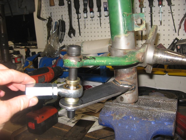
Getting the parts was a PITA, as I had to source stuff from both sides of the pond. I got the 110mm long M14 grade 12.9 Allen bolts from Grainger, as well as the 14mm drill bit. The 14mm female couplers (that mate the male rod end with the turbo tie rods setup) and some M14 castle nuts were sourced from specialty bolt supplier in SoCal. The rod ends, high-angle rod end spacers and jam nuts came from McGill Motorsports in England. I also sourced some cool rubber boots (not shown) that keep grime out of the rod ends from McGill.
I still need to drill cotter pin holes in the bottom of the Allen bolts, chuck up some round stock to make the final spacers (after I mock up the front end and see where vertically the rod end should sit to avoid bump-steer), and then the hardware side of things should be wrapped up for steering setup.
Posted by: JazonJJordan Oct 22 2009, 10:20 AM
Awesome work and rustoration! Thanks for documenting it well.
Keep it up!  -Jordan
Posted by: Justinp71 Oct 22 2009, 10:30 AM
Looking good!
Posted by: charliew Oct 22 2009, 11:48 AM
Geoff great pictures, I guess you decided 1.5 notches on the side to side clearance of the diff was a good backlash adj? If that is good it seems easy enough. It will be easy enough to turn in the driver side on the stock setup before I take it apart to see what it is before I take it apart. that way it will bo back the same. The only prob I will see that might change things is I want to put all 05 legacy stuff along with the obx inside a 96 or 02 wrx tranny that I have. The front to rear position of the pinion might be different. In order to use the 05 legacy gears I will also have to use the 05 shafts. The 05 legacy tranny I have has a busted case. I didn't get how you measured side to side bearing load on the diif though.
Posted by: strawman Oct 22 2009, 12:04 PM
... I didn't get how you measured side to side bearing load on the diif though.
Hi Charlie,
I simply followed the Suby manual instructions to set the side-side bearing load. PM me with your email, and I'll send a copy to you.
Geoff
Posted by: strawman Oct 24 2009, 12:35 AM
Finally took some pics of my modified trailing arms (with the lateral tube stiffeners that I welded in a couple of weeks ago), along with a 911 e-brake setup. My e-brake setup is a flagrant plagiarism of Paul Seyegh's setup (you can actually see the Excellence Magazine article in the background of the pictures!!!). Thanks Paul...
The first pic is of the arms, with the relocated e-brake cable mounts and the pivots -- one hooked up, and the other laid out to see the various components. With regard to the latter, I used a 3/8" I.D. bronze shouldered bushing and flat 3/8" bronze bushing, along with a 1/2" I.D. collar welded to a bent piece of 3/16" hot-rolled steel stock. I figure I can use the set-screw hole to inject grease, and use the set-screw in the collar to keep it lubed and to keep out gunk. The bronze bushings should allow an easy/unfettered pivot; the Grade-8 3/8" flanged bolt welded to the trailing arm should provide ample strength.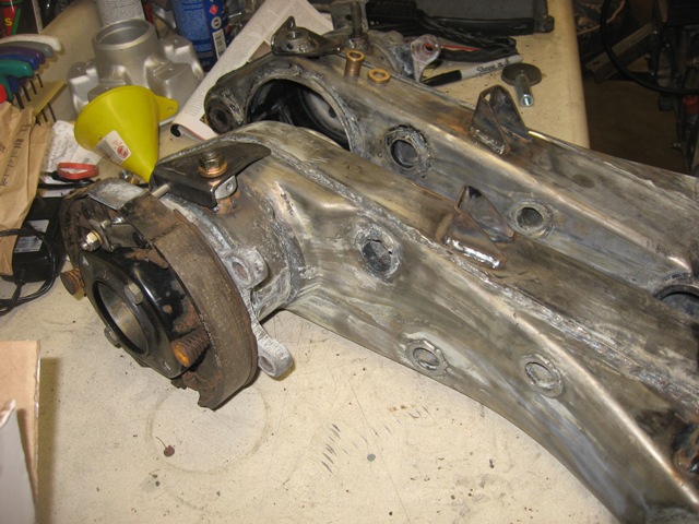
The second pic is a close-up of the various components of the pivot. The black Sharpie line depicts where the pivot will sit when the parking brake handle is released. Obviously, I haven't yet drilled a hole for the e-brake cable hook-up yet in the pivot in this pic.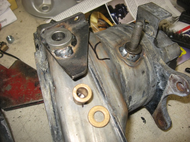
The final pic shows the e-brake cable hooked up, along with a 1/4" x 2.5" SS Allen bolt hooking up the pivot to the e-brake expander.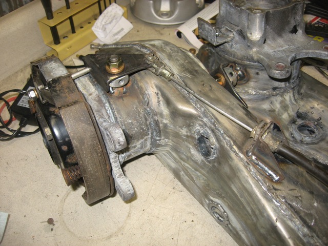
I hope to sandblast the arms and other various components tomorrow, and to epoxy primer everything. I bought some urethane semi-gloss black paint this week, and I hope to also paint all my epoxy primered suspension components tomorrow. I'm gonna forego the Bilstein green on the front struts... I like the idea of black against orange (green and orange would be too "pumpkin" for my liking).
Posted by: DBCooper Oct 24 2009, 05:49 AM
Extremely well done. You're knocking out things that I've been planning forever to get around to.
Posted by: al weidman Oct 30 2009, 11:55 PM
Geoff, just reviewed the thread so I can remember all you have done and remember to look at. My brother, Harvey will be with me, we will try to be there 2:30 to 3:00. Hasta manana, Al. 
Posted by: strawman Nov 1 2009, 11:33 PM
I finished up the epoxy primer and painting of the rear suspension parts, pedal assembly and various other parts. I also rebuilt the pedal assembly, using bronze bushings. That gave me the opportunity to start mocking up the Subaru clutch master cylinder. Below are some pics of that effort.
I ended up cutting the "face" of the mount from 1/4" steel and the "box" out of 1.5" by 0.090" wall box tubing. I still have to finalize the extended Subaru clutch master cylinder push rod, which will work using the stock 914 clutch cable "ear" -- only it will push toward the front of the car instead of pulling the cable from the rear... hard to explain, but I'll post some pics later after I finalize everything.
Of particular note is that anyone considering this mod -- either for a Suby conversion or as a mod to their 901-equipped car -- is the need to provide space for the hydraulic brake line entrance into the tunnel. Note the hole right next to & above the mount. You'll also have to offset the clutch master cylinder push rod slightly toward the passenger side of the car to avoid the throttle bell-crank. 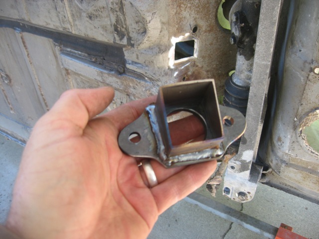
Since I need to cut the rear firewall for clearance of the turbo/downpipe, clutch slave cylinder and starter solenoid, I decided to install a 1"x2"x0.090" wall tube brace between the two rear shock towers. I plan to box in the cross-brace down to the rear trunk floor and forward to the rear firewall using 18 gauge sheetmetal to cover the above-mentioned components. Below is a pic of the passenger side gusset that I was able to start tonight before it got too dark. I'll post pics as get a chance to finish up that work.
Got a really nice visit from Al and Harvey Weidman yesterday. These guys are the real deal -- extremely friendly, very knowledgeable and willing to share their experience. Al's 1975 914 is a peach, and Harvey's 1973 911 is uber-cool. I was also able to unload a trunkful of early 911 and some unneeded 914 parts, which freed up some valuable space is my disaster of a garage!
Geoff
Posted by: strawman Nov 8 2009, 10:33 PM
Just finished welding in a 1"x2" tube between the two rear shock wells, cut out the area needed for turbo/starter/clutch slave cylinder, made a box and welded it in. Of course, those are Cliff's Notes, as this effort took about 10 hours of shop time... 
The rectangular tube is 0.90" wall, which -- along with the gusset plates -- should help shore up the rear end of car. I had the engine/trans up in the car twice this weekend to make sure I made a "clearance box" big enough to clear all components, and I had to be very careful with the cuts to the vertical double-wall section of the rear firewall lined up with the bottom of the horizontal rectangular tube. In short, I ate/breathed/snorted a lot of grinding and body-saw dust these past two weekends! 
The first two pics are of the cut-out area. Before welding everything up, I ground off the paint, cleaned everything with acetone, Metal Ready-ed everything (shown in the third pic), dried everything with air and/or heat gun, used Sem Weld-Thru Primer on all mating surfaces, and test-fit everything countless times.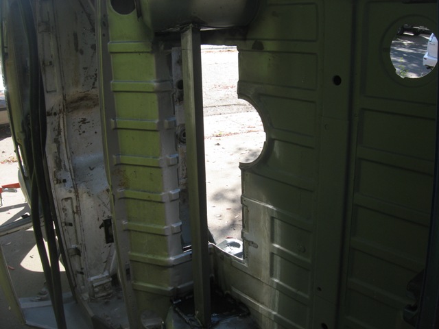
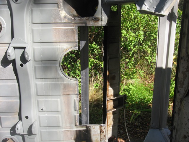
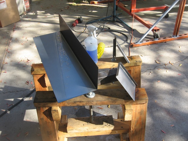
I cut the 18 gauge sheetmetal on a friend's shear, and bent all three pieces on his sheetmetal brake. Niiiiice! I then used his spot welder to mate the end caps to the main piece. I drilled out holes to rosette weld it to the underside of the horizontal tube. I didn't take any pictures of the box before welding it in, but below are two shots of the box from below and above.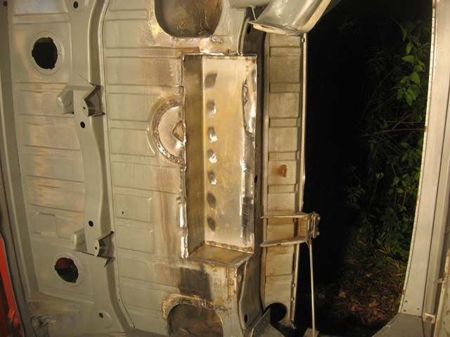
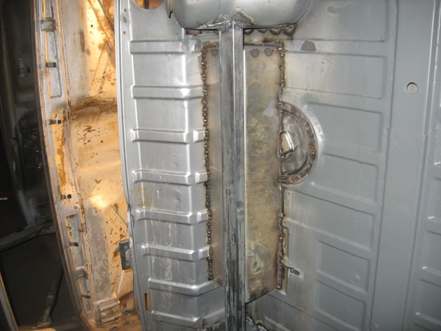
I've got Veteran's Day off, so I hope to finish cleaning up the welds on the top side, and seam weld the whole rear of the car. Then I'll weld in support bars from the horizontal bar to the top of the trans mount crossmember. Time permitting, I'll epoxy primer everything, although the forecast is for rain. 
Geoff
Posted by: charliew Nov 9 2009, 08:58 AM
Nice work. I really appreciate your work it is way better than just talking about it which is what I've been doing for quite awhile. You will be through and on another project before I even start probably.
My idea will be to use two tubes like the one you installed except one will be under the rear firewall and the other at the floor. Then two lips extending off of the towers with a small lip for strength following the shape of the pieces you put on the towers. Then a removable panel with nutzerts in the floor and it might be made from the parts I cut out to resemble the original floor. The bend would be where your tube is. I like the idea of being able to get to the turbo and stuff above the tranny and motor area. Also I might be able to also use the motor support (dog bone) that goes to the top of the tranny like the stock suby uses except I will use a short adjustable one. I was hoping that if I cut the firewall at the right spot and cut the spotwelds out of the motor side of the firewall and just remove it completely, that maybe I won't need to weld the spotweld holes up if I use a carbide burr instead of the spotweld cutter. The trick will be to have a nice transition that comes across and down that looks factory between the towers. Also in the process is the fixing of the joint on the towers that the inner firewall covers where the spot welds come loose at the longitudional on the sides.
Posted by: strawman Nov 9 2009, 06:56 PM
... I like the idea of being able to get to the turbo and stuff above the tranny and motor area.
... Also in the process is the fixing of the joint on the towers that the inner firewall covers where the spot welds come loose at the longitudional on the sides.
Hi Charlie --
Thanks for the words of encouragement.
There really is a lot of space to work on the turbo with my setup -- so much so that I scrapped the idea of a removable panel. Honestly, I believe it is more important to shore up the ass-end of the teener than to provide easy access.
I thought about cutting into & welding the joint near the towers/longs, but instead decided to tie the towers together with the horizontal bar, triangulate it to the trans x-member, and use the motor mount gusset plates to tie the longs to the rear firewall. Hopefully, my assumption is okay and I won't see separation later.
I'll look into your idea about the top dog-bone engine mount. That would allow me to easily remove the trans with the engine in the car.
Now get out into your garage and get going on your Suby-Teener project!!!
Geoff
Posted by: charliew Nov 10 2009, 08:09 AM
Geoff you are right about the structural strength being better. With a removeable panel the diagonal side to side support between the towers will be less especially with the rear firewall moved so much higher between the towers. The dogbone mounts to the tranny, so to remove the motor it would hold the tranny up but not hold the motor up while removing the tranny. Course you can always support the front of the motor while the motor mounts hold the motor in place to remove the tranny. I have bought a tubing bender with several dies to make the mounts but I really wanted to build it all out of aluminum as one friend has a machine shop and the other fabs a lot of aluminum and between them they have a lot of drops or left over material. The machine shop guy has two 4x4x4 baskets of aluminum scrap from his machine shop setting out at his farm waiting for scrap prices to go up. The only problem is my tig is only a 175 amp machine and to tig 1/2 aluminum it takes more amps than that or it will be a really slow process to stay in the duty cycle of my machine. I didn't really buy it expecting to be welding heads or heavy stuff. I have tripped my machine tigging 1/4x1 aluminum strap mainly from not waiting between welds. My fab shop buddy has two 350 millers so it's no problem for him but I really want to do it myself. He probably would let me use one of his welders if I wamted to impose on him though. He's older than me and only a one man shop, I used to be his helper at times over the last 30 years.
I can't get on my 914 for working on my house, my sons house, my sons sti and my other sons 72 super beetle it seems. Course now huntings getting started heavy.
Posted by: strawman Nov 11 2009, 11:38 PM
Today I finished up the rear trunk bracing, and completed some of the seam welding on the ass end of the car. I used 1"x0.065" wall round tubing, which I tied to the horizontal bar I installed last weekend and to the factory crossmember topside cover.
Below is a pic of the jig I built to cut the angles on the braces for each side, using two short pieces of scrap tubing, a piece of angle iron and two Vise-Grips to align things correctly for each side separately. The piece of white posterboard is used to trace the very acute angle onto the lower end of each brace. Does that make sense?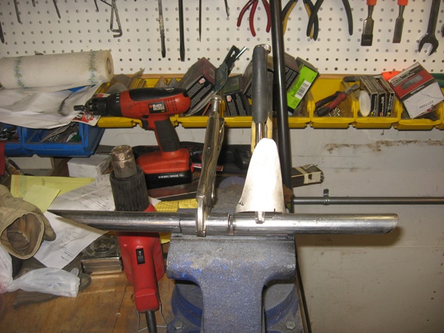
The next pic is of the two braces welded in; you can also see the seam welding to bolster the rear shock towers. I decided against welding in gussets on the topside crossmember cover after seeing how the factory doubled-up this area. 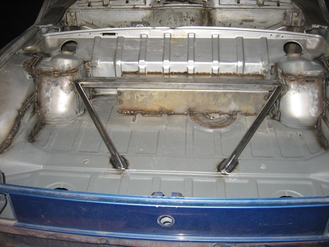
I gotta say, it is frustrating trying the weld the pinch seams along the bottom of the longs -- you just can't get the impurities out of these areas, and it is tough to get a nice weld without popping/holes. I found it best to wirewheel the seams as best as possible, use an awl to try to dig out any paint/rust/crap, and then bzzt-bzzt-bzzt small sections at a time. I'm glad I am using a rotisserie; doing it whilst laying on your back would be treacherous.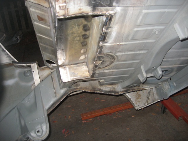
I'm gonna do some searching on the 'world tonite to see to what extent folks are seam welding the car. I gotta say I'm ready to call it good after seam-welding the area aft of the engine/cabin firewall. I wonder if it is necessary to do the car forward of that firewall, since I've already welded in the Engman long kit... anyone? anyone? Beuhler?
Unfortunately, I wasn't able to epoxy primer it, since the temps started to drop and the rain is a-comin'. I hope to do that this weekend.
Posted by: Numbchux Nov 12 2009, 12:54 AM
wow. very nice fabrication!
love the bracing there! should tighten things up very well.
I'm watching this build very closely, as my own suby swap is still in the planning stages. good to see what other people are doing.
would you say you'd need that extra clearance just for the starter and such? I plan to use a suby transmisson, but no turbo, so wouldn't need the space for that.
Posted by: strawman Nov 12 2009, 10:42 AM
... would you say you'd need that extra clearance just for the starter and such? I plan to use a suby transmisson, but no turbo, so wouldn't need the space for that.
In order to line up the trans outputs with the hubs on the trailing arms (fore/aft), you need to make some clearance in the engine/trunk firewall for the starter and clutch slave cylinder / throw-out bearing arm; the turbo requires even more room. I suppose you could just move the engine forward and/or lower to provide clearance. But just moving it forward -- about 4" just for the starter solenoid -- could wreak havoc on your CV joints; lowering the engine too much and you'll risk scraping the oil pan and exhaust manifolds as they'll hang pretty low.
Maybe there is an aftermarket starter that would permit you to "clock" it counterclockwise so the solenoid won't be in the way, but I couldn't find it in my 'net searches. There is probably also an aftermarket hydraulically controlled throw-out bearing setup that would permit you to get rid of the top-mounted slave cylinder & T/O arm. Finally, there are pre-made headers for sand buggies that exit the exhaust and mount the turbo in front of the engine. However, all of those options would require $$$, time and fabrication (especially for oil flow to the turbo if mounted up front). Since I'm a CSOB, I opted to cut out the trunk floor...
Good luck with your project!
Posted by: Numbchux Nov 12 2009, 12:08 PM
Thanks for the info! I'm a CSOB too....but I have very little welding experience, and no equipment. so something like what you've got there would be fabrication $$$ for me...
but, sounds like it'll be necessary. I plan to run a cable-clutch trans, so I'll have a little more room there, but not much. I'll have to play it by ear a bit.
Thanks again, and keep up the awesome work 
Posted by: charliew Nov 12 2009, 09:13 PM
I had a ss header that my son took off his sti when he changed to a perrin header and I shortened it to be the 4 5/8 distance down that matched the depth of the 8 qt pan I built. I do kinda like putting the turbo inbetween the motor and the firewall but that will add more heat to the area that a ic will need to be over. Also the exhaust pipe will be a bigger hassle with the front mount turbo. I want to use 2.5 or 3.0 id exhaust pipe.
In my opinion the turbo suby is the only way to do this conversion and it will take a person with good fab skills to make it look factory and clean. The reason I think it should only be the turbo version is that the power of the turbo suby is the only reason to do a swap. the na suby will need too much hotrodding to get it up to 200hp and that cost will need to be added to the equation. When the motor gets to 200hp the clutch will be too weak and that will need a upgrade it just keeps going on and on. Once you get used to 160hp you will want more.
Posted by: strawman Feb 10 2010, 12:16 AM
It has been a while since my last post, but I've been busy. My camera memory card took a dump, so I couldn't take any pics of the epoxy paint work on the rear half of the car - including both sides of the firewall (engine bay and passenger compartment), the rear trunk area, and the whole rear underside of the tub. I'll try to snap some pics this weekend now that I've got a new memory card.
Since my last post, I bought a Harbor Freight powdercoat gun and picked up a free electric oven on Craigslist. The biggest pain was wiring a 30 amp 220v fusebox for the oven, but it works great. I'm using a "Wet Black" finish from Columbia Coatings. Now that I have this setup, I ended up media blasting the suspension arms that I painted a few months ago (that epoxy was tough!) and powder coating them, as well as a bunch of smaller parts. Yes, you can BARELY fit front A-arms and rear trailing arms in a standard oven. Below are some pics: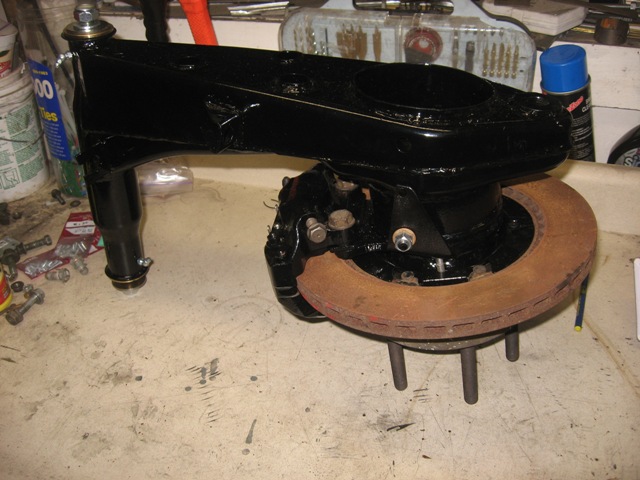
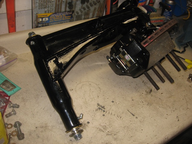
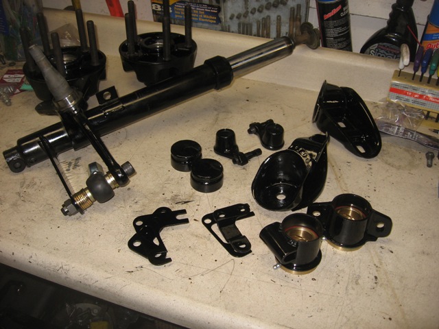
You can see the 911 e-brake setup on the trailing arm, based on Paul Seyegh's article in Excellence magazine. I'll put some new brake rotors on before I get the car rolling, since those in the pics are right at the wear limit and they're quite rusty.
You can also see the Elephant Racing Products polybronze bushings front and rear. The chintzy 5mm grease fittings broke off during assembly, so I took Eric Shea's advise and replaced them with 6mm fittings. I talked to Chuck at ERP about this, and he says he's also making the switch -- if you're considering it, be sure to ask for the larger fittings upfront. I ended up using a Dremel to cut the depth of the 6mm threaded end; otherwise, they stick up kinda high.
You can also see the bump-steer setup that I've developed after raising the spindles. I'll use a bunch of stacked washers during setup, and then make up some nice powdercoated spacers once dialed-in. It took about 60 minutes in the oven to bake out the remaining grease in the strut housings; you don't want to attempt powdercoating an item with grease/oil on it -- the smoke can ruin the powdercoat finish while its curing. In fact, the oven is a great way to remove any residual grease & oil from any parts that don't have rubber/vinyl gaskets.
I bought caliper rebuild kits from Eric Shea, so I disassembled the M rear calipers before powdercoating the components, and then powdercoated 'em. They look nice, eh? The front aluminum S calipers were recently rebuilt by the PO (with stainless pistons, no less!), but I replaced the seals anyway. I won't be powdercoating those aluminum beauties, though. I'll be running Pagid Blacks up front and PBR Metal Masters in rear to start; I may go for something more aggressive after I sort the car.
Posted by: strawman Feb 10 2010, 12:22 AM
I also cut the radiator inlet hole in the front of the car, and devised the radiator mounting setup. I am using a Griffin 25241 radiator (27.5' wide x 15.5" high x 3.0" thick). Details can be found at http://www.summitracing.com/parts/GRI-1-25241-X/. 
I am also using a Lincoln Mark VIII radiator fan that I got at a local Pick-n-Pull for $35. This two-speed brute pulls 4500cfm on the highest speed, and is used by a lot of the rockcrawling Jeep crowd. 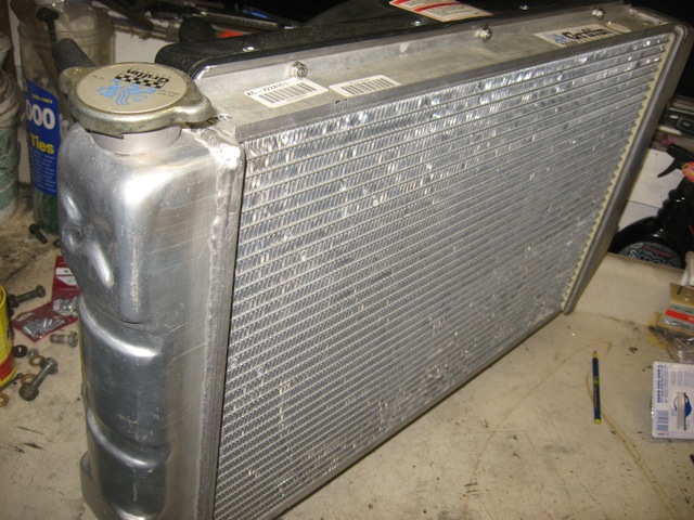
I took some camera phone pics of the shrouding I constructed out of aluminum sheet to force all the air through the radiator, since the fan is so much bigger than the radiator core -- but not surprisingly those pictures are so low quality that they are not worth posting. Suffice it to say that ALL of the air has to pass through the radiator core.
Posted by: FourBlades Feb 10 2010, 02:16 AM
Nice progress!
This is a great build, looking forward to more pictures.
John
Posted by: strawman Feb 10 2010, 03:58 PM
I thought I'd post the crappy camera photos anyway, since they'll help me remember how everything went together (getting old sux!).
First up is a pic of the fan mount/shroud. I used 16 ga. aluminum scrap sheeting, as well as some aluminum angle to give it some extra oomph.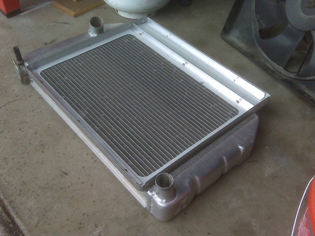
Next up are two pics of the comparative weights of a fully-loaded aluminum 911S front caliper vs. a fully-loaded rear cast steel 911 M caliper. I thought the 911S caliper would be considerably lighter, but then realized the front calipers are much larger than the rears. Note the homebrewer's grain scale -- not too accurate, but it has helped me brew many gallons of all-grain beer!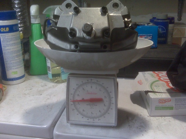
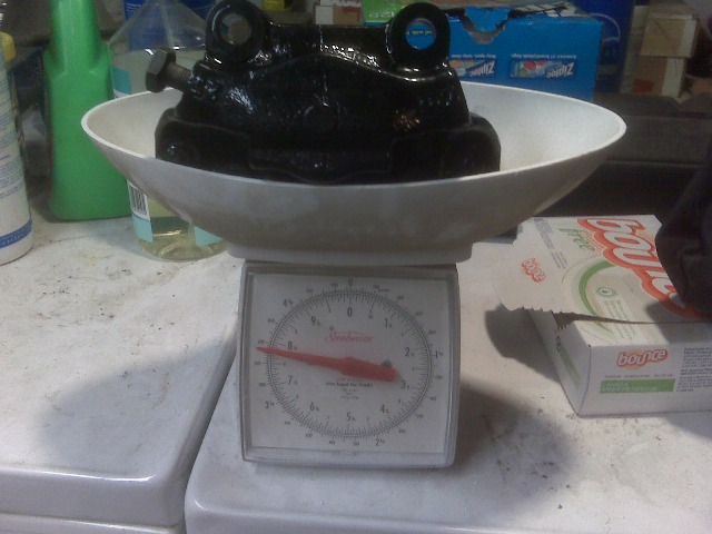
Finally, I mocked up the rear trailing arm with a 21mm spacer and stuck on a 16x9 BBS rim with a junk tire. Definitely need the flares!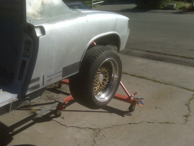
Posted by: strawman Mar 30 2010, 10:06 PM
I've made some pretty good progress over the past six weeks (just been too lazy to post any pics here).
I have finally nailed down my shifting mechanism, based on a early Toyota MR2 shifter, and 9' and 11' Teleflex TFXtreme push-pull cables (I originally bought two 12-footers to help me mock things up). I didn't get a chance to take pics of the entire thing all bolted together, but below is a pic of the shifter mount (swiss-cheesed to reduce weight), which bolts to the factory holes in the 914 floor. I've also included a photo of the combination trans mount and cable mount. I powder-coated both of these mounts and will powder-coat the various pieces of the shifter mechanism later this week. I'll also take some more pics soon of everything in situ. 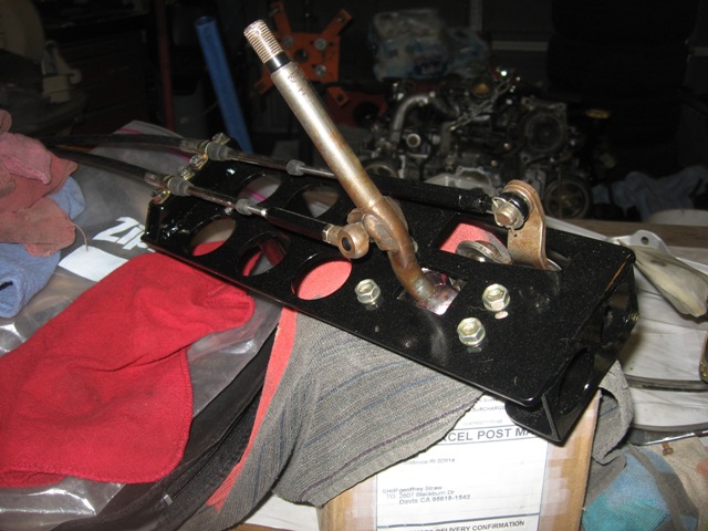
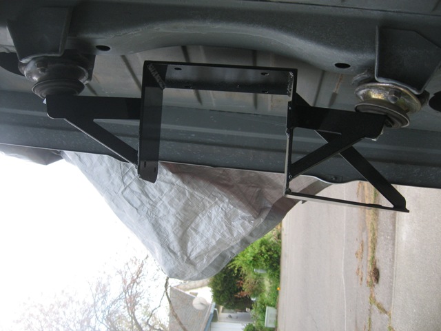
I've also welded in a reinforcement tube that ties together the front A-arm mounts, as well as the lower radiator mount and upper mount/crossbar. The lower "rail" of the radiator sits on top of the square rubber feet, and I'll weld on brackets that will hold rubber mounts for the "rail" at the top of radiator. You can also see the rough-cut holes for the radiator air intake.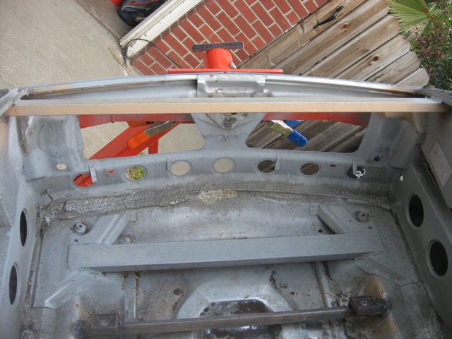
Posted by: strawman Mar 30 2010, 10:18 PM
Due to furloughs at the campus at which I work, I was able to spend a full day working on something I've been avoiding -- dealing with the rust damage in the area between the cowl and driver side fender. I first dug out the seam sealer in the area, and media blasted what I could get to. Here is a pic of the planned cut-out area.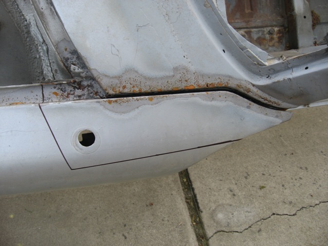
Next is a picture of the rust and nasty-ass seam sealer from the inside of the door jamb. Ugh!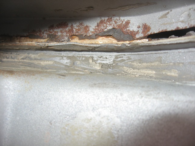
Here is a pic of the fender top cut out. Look at all the tinworm work around the remaining seam sealer...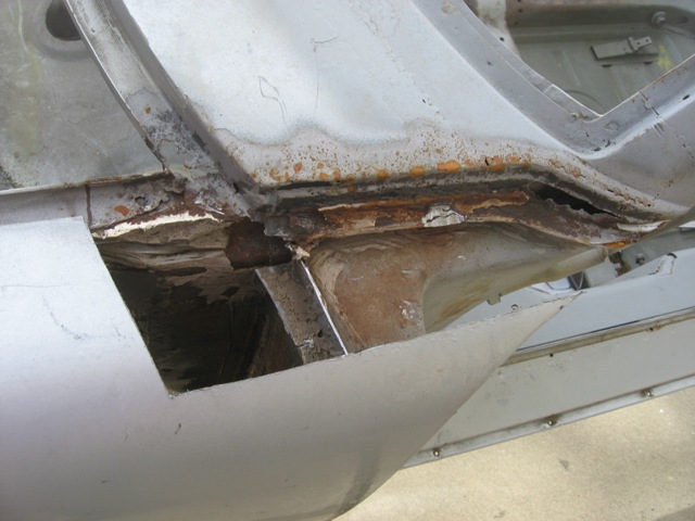
Check out the area after further cleaning, grinding and media blasting.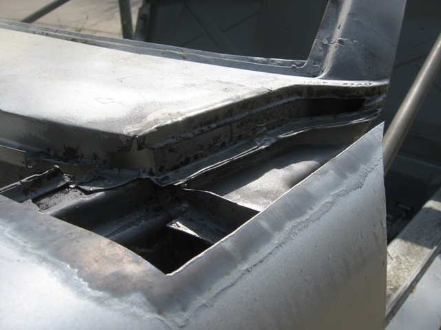
Here is a shot of the repair pieces welded in, but not yet smoothed.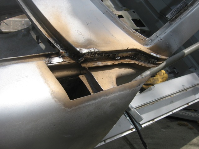
Posted by: strawman Mar 30 2010, 10:31 PM
Finally, here is shot of the fender top cut-out being welded back in. Unfortunately, my camera batteries died and I didn't get a shot of the area all smoothed out...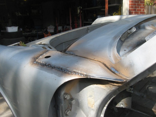
The hood seal channel was pretty nasty, too. Here are some pics of the before, during and after for most of the repairs.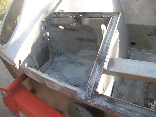
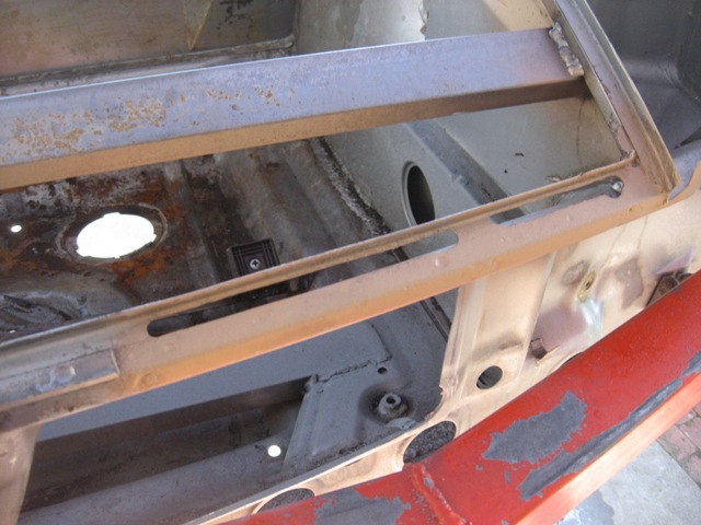
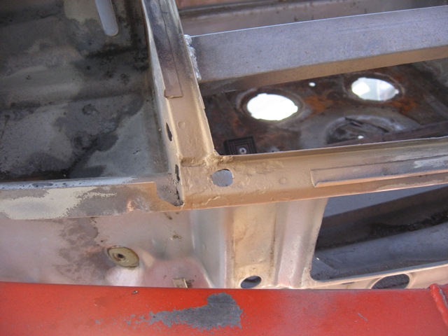
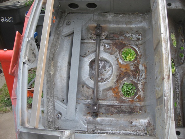
Again, my battery died before I could snap better pictures. I've got a few small patches to complete in the frunk, then I'll strip the entire area and epoxy primer it.
Posted by: strawman Mar 30 2010, 10:33 PM
Last up for tonight are a couple of pictures of the front sway bar mount.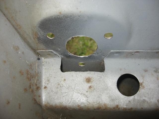
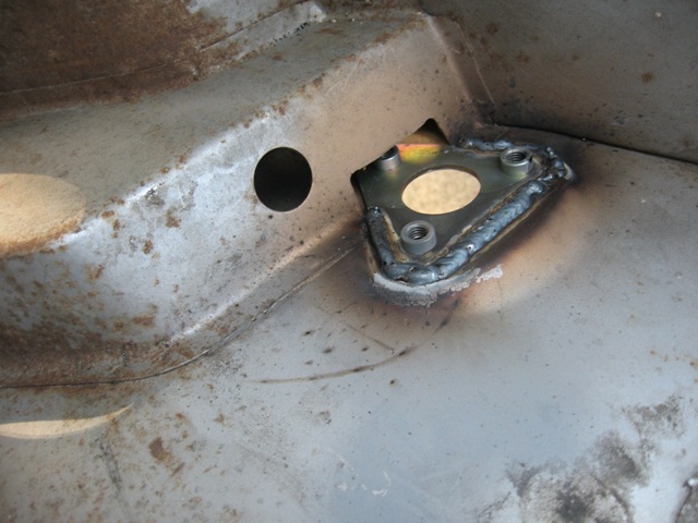
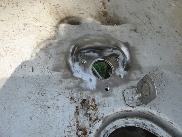
Posted by: Justinp71 Mar 31 2010, 12:28 AM
Lookin Good!!! 
Posted by: strawman Apr 18 2010, 06:09 PM
Finally got some time to work on the fuel delivery system. I want to use the Subaru in-tank fuel pump instead of an in-line one, so I had to move the fuel gauge sender so that I could line the Suby pump up with the 914 fuel tank sump. Kinda difficult to explain, so see the pics below.
First up are the two "rings" made out of 1/8" steel stock. These will be welded inside the tank and will be tapped so the Suby pump and 914 sender unit can be screwed in. You can also see where the old sender hole was, which I'll weld up in a pic below. The area where the new pump hole was cut is not perfectly flat, so I had to hammer/dolly most of the area, and shrink the metal at "six o'clock" and "three o'clock."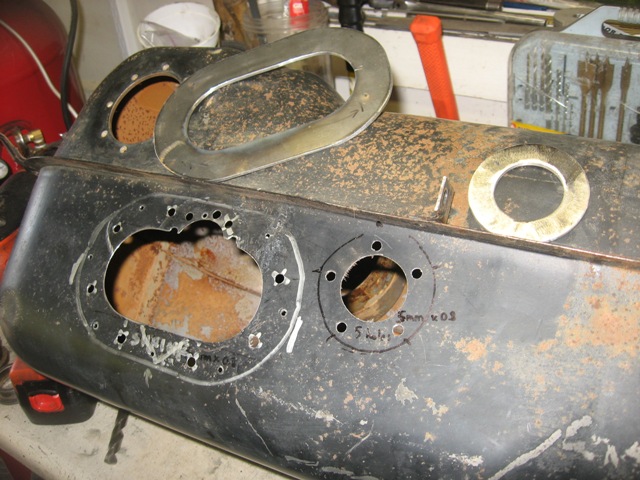
The next two pictures show the stock Suby fuel pump and bracket, as modified to align the fuel pump pickup and the 914 tank sump. In short, I had to cut the Suby bracket to put two elbows in it, bend the output pipe, and weld in a reinforcement/triangulation piece in the "outside" elbow for strength. It barely fits in the new hole cut into the tank, but it will work famously.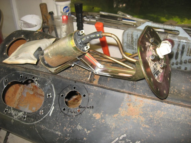
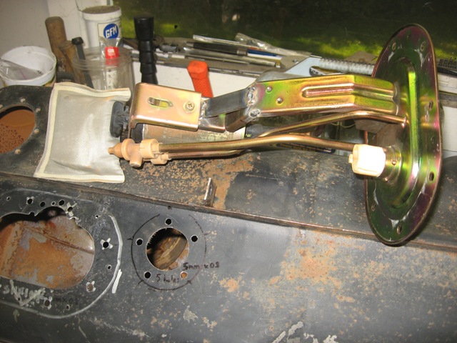
Posted by: strawman Apr 18 2010, 06:22 PM
The next pic shows the rings welded into the inside of the tank, as well as the plug welded in (at twelve o'clock) to fill in the remaining portion of the factory 914 fuel level sender hole. I also drilled the mounting screw holes and tapped them, using an m5 x 0.8 screws. You can also see the areas that I had to shrink (heat up & quick chill) to provide a flat mounting area for the fuel pump.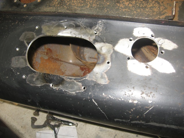
Finally, here is a pic of the fuel pump and sender mocked up.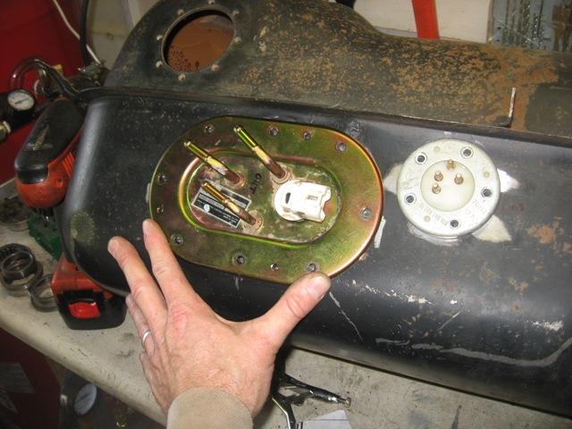
I still need to send the modified tank out to get treated/sealed. Then I'll paint the outside with epoxy primer and paint it SEM Trim satin black. I still need to fabricate plugs to seal up the factory 914 bottom tank outlets.
Posted by: BIGKAT_83 Apr 18 2010, 06:39 PM
Strawman I had done the one for my Subaru conversion last year. I must have a different subaru mount. I didn't need to mod it to fit the 914 sump at all. It line up perfect and the subaru fuel level sender even works with a full stroke,but does read backwards from the 914 one. It reads empty with a full tank. 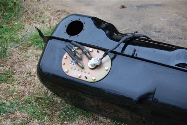
Bob
Posted by: rickthejetman Apr 18 2010, 07:13 PM
any reason you guys went with the in tank pump instead of the inline?
Posted by: strawman Apr 18 2010, 07:57 PM
Strawman I had done the one for my Subaru conversion last year. I must have a different subaru mount. I didn't need to mod it to fit the 914 sump at all. It line up perfect and the subaru fuel level sender even works with a full stroke,but does read backwards from the 914 one. It reads empty with a full tank.
Bob
Hi Bob --
Interesting. Is that the fuel pump setup from an SVX? I checked the ones for Imprezas and Legacies at local pick-n-pull type places, but couldn't find an SVX to see if it would work better. So I decided to modify the turbo Legacy fuel pump that I already had. I also decided to scrap the idea of the Suby fuel level sender, since I know the 914 sender "talks" to the 914 gauge... the mods I made to the fuel pump bracket also interfered with the Suby sender and made it impossible to fit inside the oblong hole.
Any updates on your project? I was in Athens last week -- I wish I thought to look up Athens-area teeners before I left. I woulda liked to have seen your project.
Geoff
Posted by: strawman Apr 18 2010, 07:58 PM
any reason you guys went with the in tank pump instead of the inline?
I wanted to use the Suby fuel pump because I know it communicates with the Suby ECU, and it also matches the return lines that Subaru installed from the factory. I suppose that an inline fuel pump would work...
Posted by: al weidman Apr 18 2010, 10:45 PM
Looks really good Geoff, lots of little special projects coming together. I'm going to start stripping stuff off my car to get ready for the rotissorie. I busted the windshield already, it must have been too cold. Maybe I could come by the weekend of the trip to Mark's and check out your progress. Al.
Posted by: strawman Apr 20 2010, 09:56 AM
Looks really good Geoff, lots of little special projects coming together. I'm going to start stripping stuff off my car to get ready for the rotissorie. I busted the windshield already, it must have been too cold. Maybe I could come by the weekend of the trip to Mark's and check out your progress. Al.
Sounds good, Al. I plan to help out on the Limo project on May 1, too. Sorry to hear that you broke your windshield...
Geoff
Posted by: Justinp71 Apr 20 2010, 12:20 PM
Man way to go Geoff... I cant wait to see this out at an autocross
Posted by: strawman May 25 2010, 08:24 PM
Finally finished up the fuel tank. I ended up using a (modified) POR-15 tank sealing kit to re-finish the tank. By "modified," I mean I bought a gallon each of Marine Clean and Metal Ready, as well as a quart of the US Standard Tank Sealer, for the same price as the "standard" kit, which includes a fuel stabilizer that I don't need right now.
I searched the internet and found a good write-up on how to refinish the inside of a tank, found at http://www.ratwell.com/technical/FuelTankRestoration.html
First I stripped the tank of the factory paint, using a wire wheel on my 4-1/2" grinder, some 80-grit sandpaper and a lot of elbow grease. I then used Muriatic Acid to remove the rust inside the tank. It is nasty stuff, so be careful; wear thick rubber gloves and eye protection. I poured about two cups of acid and a Wal-Mart pack of steel slingshot pellets into a couple of inches of water inside the tank. You need to seal up the tank (I used Gorilla tape) so that you can slosh the acid solution around in the tank for long enough to make your arms REALLY ache. You'll need to repeat until the solution comes out clean, and the inside of the tank looks clean. I collected the effluent spread out equally into four 5-gallon buckets, and used almost 10 pounds of Baking Soda to neutralize it. Being a homebrewer, I already had pH strips to test the resulting yuck to make sure it was safe (pH ~7.0) to pour down the drain.
Next comes the Marine Clean in a 1:1 hot water solution; be prepared for a lot of suds! You want to slosh this stuff around, and let it sit on each side of the tank for 30 minutes at a time between sloshings to make sure all of the varnish is removed. This stuff is biodegradable, so I poured the effluent into a bucket and then tossed it onto the roadway in front of my house. I did this four times until the effluent was crystal clear.
Next up is the Metal Ready, which I left inside on each side for 5 minutes on each side at a time. No real need to slosh it around violently, since you really only want to keep the stuff in contact with the metal to keep it wet. You can reuse this stuff if you strain it; I used a paint strainer, although the previous steps meant the effluent was pretty darn clean and the filter didn't collect much debris.
Use an air nozzle, followed by heat gun, to completely dry the tank inside and out. Re-seal the holes with tape, mix the US Standard Tank Sealer well (apparently they don't want you to shake it, but it is a bit "chunky" and requires a lot of mixing with a wooden stirrer), and then pour it in. Finish up the taping, and slosh it around per the instructions. The toughest part is getting all of the excess sealer out of the tank -- it is damn near impossible to do that, so I canted the tank on a lower corner to collect the excess (about 1/8").
A pain in the ass? Definitely. Worth it to have it done professionally? Sure. But I already bought the materials from my paint supplier (Rainbow in Woodland, CA) before McMark suggested I have it done professionally; he also recommends the Caswell kit, but I already purchased the POR-15 kit before he advised me. And I couldn't find a radiator shop nearby that would take on this project. That and I'm a stubborn/CSOB who enjoys completing a job myself...
I shoulda taken more pics of the cleaning in progress, but I was lazy (and my arms were too tired from sloshing around the various chemicals to hold up a camera!!!). Here are a few pics of the final product.
Inside the finished tank: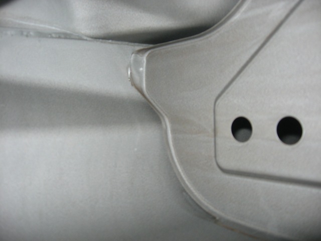
Outside of tank epoxy primered: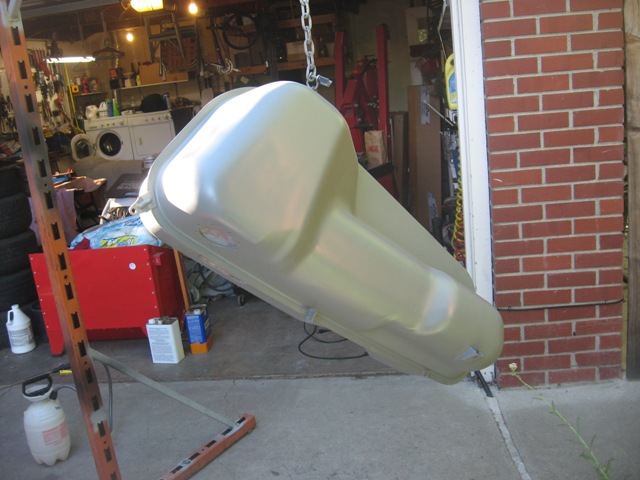
Finally, tank painted: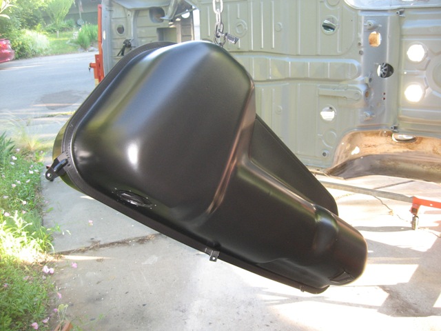
Since I'm using an in-tank modified Subaru fuel pump, I won't need the factory tank outputs. I ended up cutting small disks out of aluminum stock to block them off. I decided against welding them up in case I ever need to drain the tank in the future.
Posted by: strawman May 25 2010, 08:33 PM
I also refinished the underside of the car. Another PITA project, but I am very happy with the results. I spent many hours with wire wheels, 80-grit sandpaper, scrapers and a LOT of elbow grease. I'm just glad I'm using a rotisserie; you guys that have done this while laying on your back are truly heroic!!!
Below is a pic of the underside completely stripped, including a couple of small rust holes that had to be patched: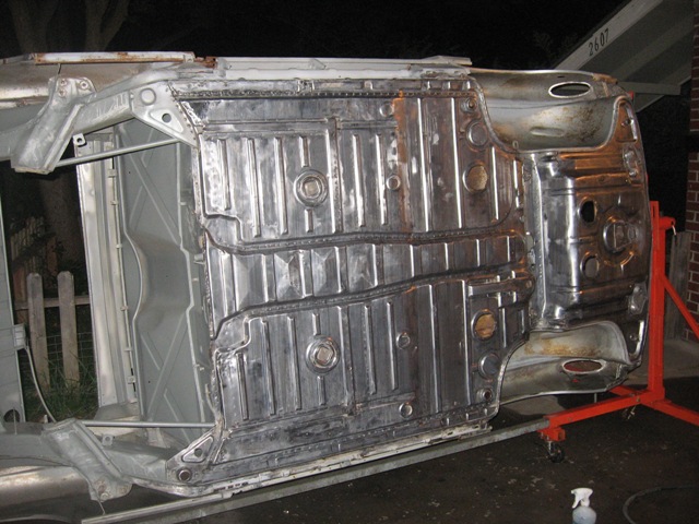
Next up is the metal Marine Cleaned and Metal Readied: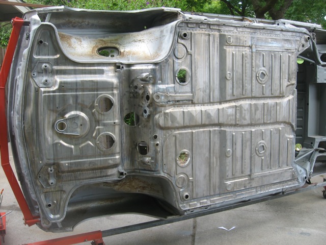
Finally, here is the underside epoxy primered. You can see the Suby transmission mount bolted on in this picture, too.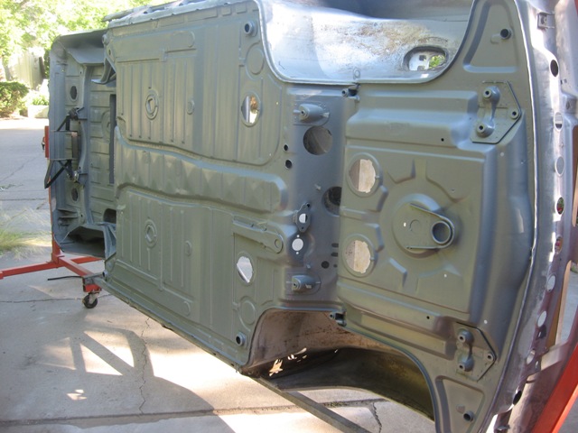
I'm hoping to strip/prime the fenderwells and front trunk this week, and possibly begin welding on the flares this weekend (time and weather permitting!). Stay tuned!
Posted by: charliew May 25 2010, 10:11 PM
How did you keep the metal ready from etching your driveway?
Posted by: strawman May 25 2010, 11:11 PM
How did you keep the metal ready from etching your driveway?
I didn't... the Metal Ready just turns portions of it white. The concrete is cracked pretty badly already, so I'll prolly need a new driveway in the few years anyway. Gotta love an understanding wife

Posted by: computers4kids May 26 2010, 08:02 AM
Geoff,
Good Read! You are quite a craftsman...and that is one clean tub bottom. Now that your'e good at it, I'll send you my project
Mark
Posted by: andys May 26 2010, 09:57 AM
"A pain in the ass? Definitely. Worth it to have it done professionally? Sure. But I already bought the materials from my paint supplier (Rainbow in Woodland, CA) before McMark suggested I have it done professionally; he also recommends the Caswell kit, but I already purchased the POR-15 kit before he advised me. And I couldn't find a radiator shop nearby that would take on this project. That and I'm a stubborn/CSOB who enjoys completing a job myself..."
Strawman,
I had my tank done "professionally" and was very disappointed with the results compared to the DIY results I've seen here and on other threads. The radiator shop I took mine to came highly reccomended by a reputable classis restorer. When I dropped my tank off, the guy seemed very confident, said he's done hundreds, and had a display of business cards from restorers and hotrod shops on his wall. I've driven by the shop many times and know he's been in business for many years.
So what I got back was a tank that I first noticed had a dent in the top (my tank was perfect going in). The outside was painted a hideous gloss black that included several runs. I looked inside and saw it was coated with a white coating of some kind that in retrospect looked nothing nearly as nice as in your example or others'. Lastly, there was some kind of soldered patch that was explained as a hole necessary to get the solution to properly flow or circulate during the process. He said this is common practice.
So maybe another shop would have done a better job, but after this experience I'd prefer to do the next one myself thinking "if you want it done right, then do it yourself."
Andys
Posted by: Dr Evil May 26 2010, 01:58 PM
Wow, I am just looking at this now. I didnt realize that the guy I met at WCR was capable of this 

Posted by: charliew May 26 2010, 09:04 PM
I have a 66 800 scout that is sorta in the middle of a frame off restoration and I took both tanks to a good shop and they did a terrible job. I could look inside and see where they didn't get the sealer all over the inside. The other ended up looking like swiss cheese. Thats why I only do them myself now. The restomotive stuff is very impressive. When you drain the excess out you get some really durable stuff to examine. It's pretty much like a urethane liner. On the tanks I've done I use to use gravel but that was on mainly motorcycle tanks a long time ago, now I use the muratic acid with big flat washers to break the goop up.
My shop and approach is about ten years old and metalready looks like muratic acid on it so I have to plan ahead when I use it. I have a hard time using it on real big surfaces because if it dries it will stay in the seams and is hard to flush off before I paint over it.
Boy that tub is looking really nice.
Posted by: McMark May 26 2010, 09:38 PM
That SEM trim black is beautiful, and looks like a darn near perfect match for OE. 
Doing it yourself takes awhile (I just did a tank with the Caswell and I have about 3 hours in it), but at least you know it's done right.
Posted by: al weidman May 26 2010, 10:18 PM
Geoff, looking really good. BTW, did we win the photo contest? You are going with Phoenix Red or an orange color, right? I can picture it with those flairs and BBS's. Had a great time at WCR with you the wife and friends. How do you spell that tequila? Cardoza? Al.
Posted by: strawman May 26 2010, 11:08 PM
Geoff, looking really good. BTW, did we win the photo contest? You are going with Phoenix Red or an orange color, right? I can picture it with those flairs and BBS's. Had a great time at WCR with you the wife and friends. How do you spell that tequila? Cardoza? Al.
Yeah Al, we won it. I instructed Rob-n-McMark to give the WCR-engraved mug to you since you were the driver and I was merely the snapper. You should ask Rob to bring it with him to the Donut Meet this weekend...
Phoenix Red (or Giants Orange, as I like to call it) is the color I plan to paint this frankenstein of a car.
I really enjoyed hanging out with you and the rest of the West Coast teener folks!
Posted by: McMark May 27 2010, 11:09 AM
Cazadores!
Posted by: jeeperjohn56 May 27 2010, 12:38 PM
.Geoff, Your doing a great job,you'll have a nice built car when done keep up the great job and good luck. John
Posted by: strawman Jun 15 2010, 02:25 PM
Been a while since I last posted, but I have been working hard on my car. I finished welding up the radiator support system supports. I used a thin-wall 3/4" square vertical tubes that will be the basis of the radiator top supports, and I tied them together diagonally using the same tubing. Here is a picture from the backside: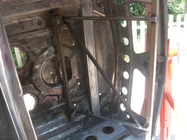
I also seam welded the strut towers / wheel-well area. Here are some pictures before grinding them smooth (to the extent possible). Note that I welded in short ~1" bursts and cooled them with compressed air prior to proceeding to avoid too much warpage.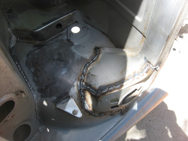
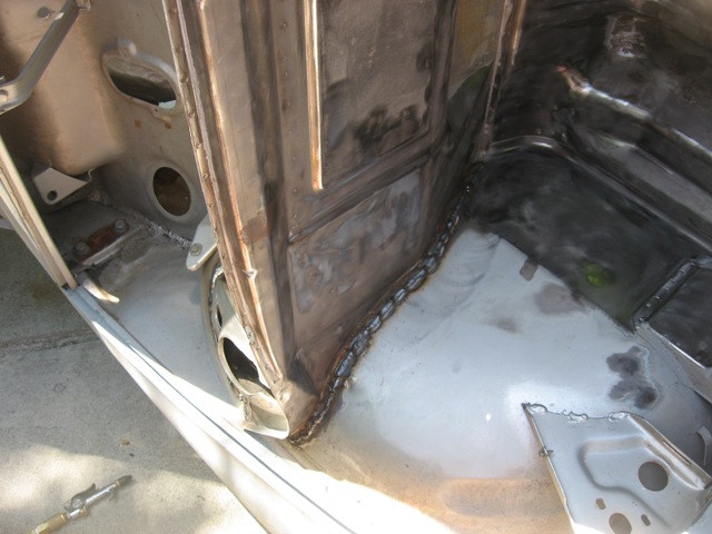
Here is a picture of the area ground down smooth.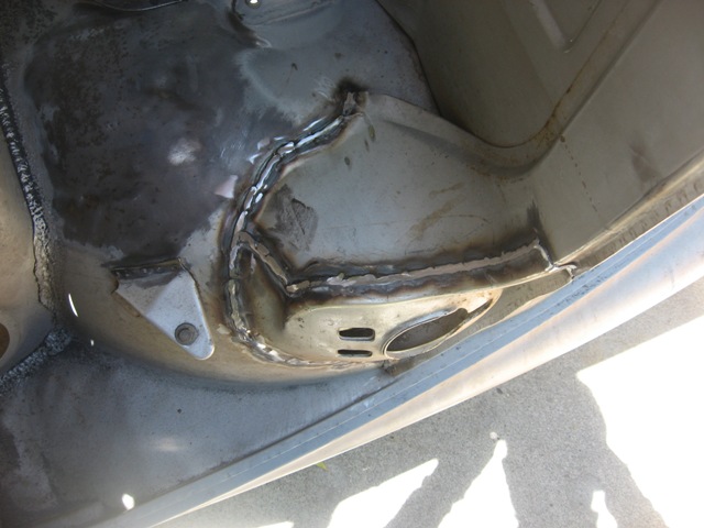
Has anyone bothered to seam weld the horizontal firewall seam that connects the two strut towers? It seems like that wouldn't be too critical an area, since the metal is already corrugated from the factory for strength.
I'm contemplating two diagonal supports from the firewall (near the strut tops) to an area near the front A-arm mounts to triangulate that area. Or is the car too floppy from the area behind the strut towers to the long that I'd be wasting my time? If I end up cutting out the wheelwells to exhaust the radiator air (if the hood exhaust idea doesn't work), I'd imagine diagonal braces would be helpful... any opinions on that?
Posted by: strawman Jun 15 2010, 07:32 PM
More pics from today's efforts. First up is the front fender tacked on. I neglected to snap a pic of the cut-out and preparation...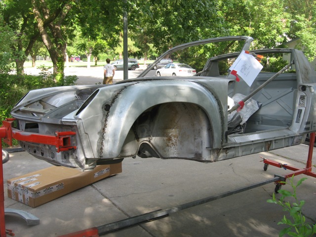
Next up is the rear fender cut out and ready to accept the AA flare.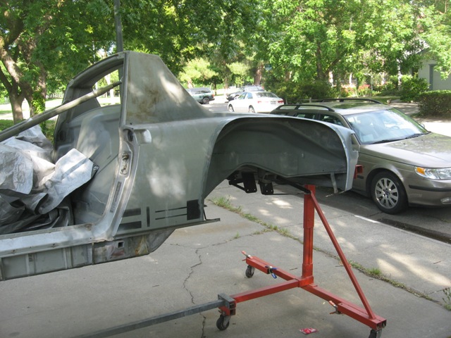
Finally, here is a pic of the driver's side fenders tacked on. I hope to tackle the passenger side in the coming days, and to spend some quality time this weekend finishing it up (my wife and daughter are heading to the in-laws for a week on Thursday!). 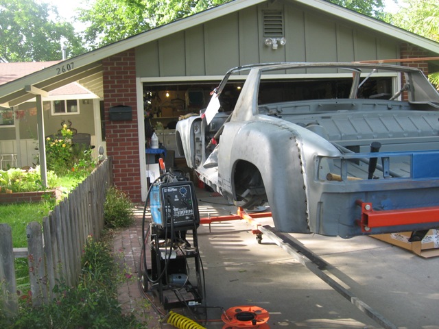
Posted by: Spoke Jun 15 2010, 08:20 PM
Nice job.
You have inspired me to move away from the computer and watch some TV.
Keep up the good work.
Posted by: Zaney Jun 15 2010, 08:53 PM
Awesome work, as usual Geoff!!!
Hope that you keep up the momentum! It is always fun and educational to read your updated posts, especially for Suby Noobies like me!
Cheers!
Nate
Posted by: Spoke Jun 16 2010, 04:48 AM
Nice job.
You have inspired me to move away from the computer and watch some TV.
Keep up the good work.
I looked back at what I wrote and hope it wasn't taken offensively. I was joking about the TV while I was bumming out that my own 914 project wasn't getting worked on because of other priorities.
My 71 914 was going to be a Ru powered beast too until it was crunched from behind.
Posted by: strawman Jul 10 2010, 05:17 PM
I have been busy helping get our "Team Tinyvette" Opel GT ready for our 24 Hours of Lemons race at Thunderhill next month, so my teener project has been put on the back burner a bit.
Also, after realizing that the driver side rear flare was a dud (after welding it on!), I finally received a replacement one yesterday from AA -- that is a whole 'nother story not worth sharing here. 'Cause my mother taught me that if you don't have something good to say about someone, then...
Here are some pics of the all four flares welded on. Notice the bad shape of the driver side rear in post #143 above compared to the replacement one below; pay particular attention to the lower rear section. See how the dud above is "boxier?" It is also about 3/4" wider than the correct flare. Well, that was about four hours of my time I'll never get back... not to mention all the hair I pulled out. I think my neighbors want to have me committed after all the curse words uttered.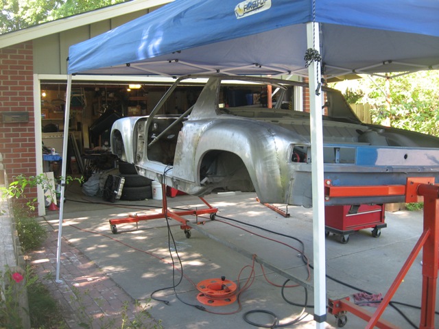
Below is a pic of the passenger side flares welded on. I still have to finish the lower flanges, since they don't match up exactly with the factory "double bend" area.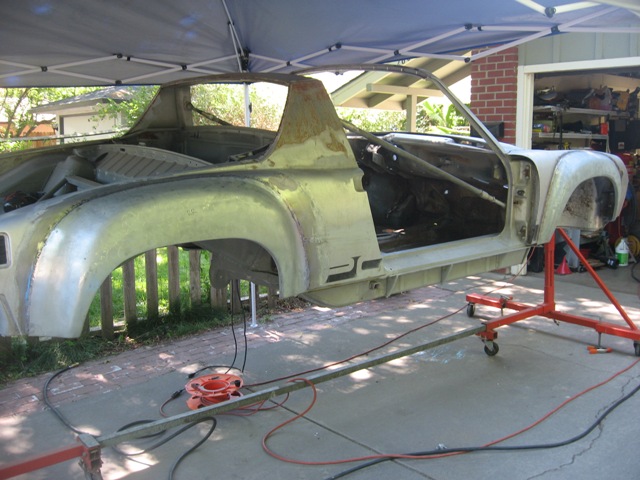
I finished up seam welding the front trunk area of the car, and will epoxy paint all bare metal tomorrow morning when it is cooler (it is 95 degrees outside right now). I'll take some pictures of that seam welding later this evening and add them to this build blog after my camera batteries recharge for a couple of hours.
Posted by: strawman Jul 10 2010, 11:51 PM
Okay, the camera batteries were charged, so here are some pics of the front trunk ("frunk"), gas tank area, driver side inner fenderwell, and underside (with fresh burns on my epoxy paint!). I'm not sure if I actually stiffened anything to a measurable degree -- but it was one of those "while I'm in there" kinda things. I also spent some time doing some final front trunk rubber seal channel repairs. In total, I've probably got 30 hours into these tasks...
First pic is of the frunk as stripped and modified for front-mount radiator and welded in forward A-arm support. I've stripped out all of the factory sealant, and will re-seal once I epoxy prime the area. My plan is to Marine-Clean and POR-15 Metal ready this area tomorrow morning so's I can paint it before it gets too hot (supposed to get up to high 90's!).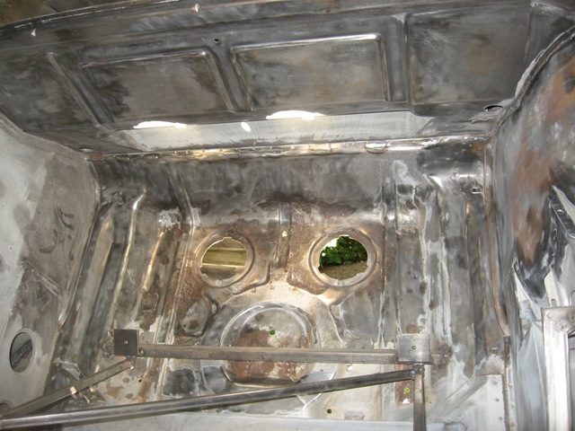
Next pic is of the driver's side inner fenderwell. Here you can see the where the seam welding in the gas tank and upper front strut mount areas burned through (nicely, I might add). I'll strip this in the coming days and get it ready for epoxy primer painting. BTW, I've decided not to to weld in an outer sway bar support, since the jury is still out on whether that is necessary -- especially since I've seam welded the area around it. You can also see the flare weld-through, too, in the upper portion of the photo.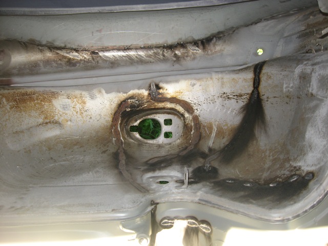
The next pic is of the gas tank area. Again, I've stripped out all of the factory sealant, sanded down to metal whenever I found any evidence of rust underneath the factory paint (in some places I had to spot sandblast), scuffed the paint in all other areas, and will prep/epoxy prime tomorrow. Bottom line is that this is worst PITA so far -- and no one will likely see this area ever again!
Finally, here is evidence of proper weld burn-through on my recently epoxy-primed bottom. Oh well, epoxy primer isn't THAT expensive...
Posted by: J P Stein Jul 11 2010, 07:54 AM
I went with the "if there's a seam, weld it" philosophy.....since I was there.  This included those on the spreader bar.
If nuthin' else, it keeps the water out.
Attached thumbnail(s)
Posted by: J P Stein Jul 11 2010, 08:11 AM
BTW, my first look at your thread.....damn nice work.
The shitbox needs a major HP infusion......300-350 at the wheels seems like a good plan. A turbo Subie may be the ticket. All's fair in love, war & XP.
I'll pay more attention to your thread in the future.
Posted by: strawman Jul 11 2010, 02:21 PM
Thanks for the compliment, JP. I've read a whole bunch of your posts, and I consider your word on building a car to be almost gospel. I neglected to seam weld the spreader, but I didn't cut any portion of it out like you did for your fuel cell. So I hope that it'll suffice...
Below are a coupla photos of the frunk, with two coats of epoxy primer. Glad THAT is done! 
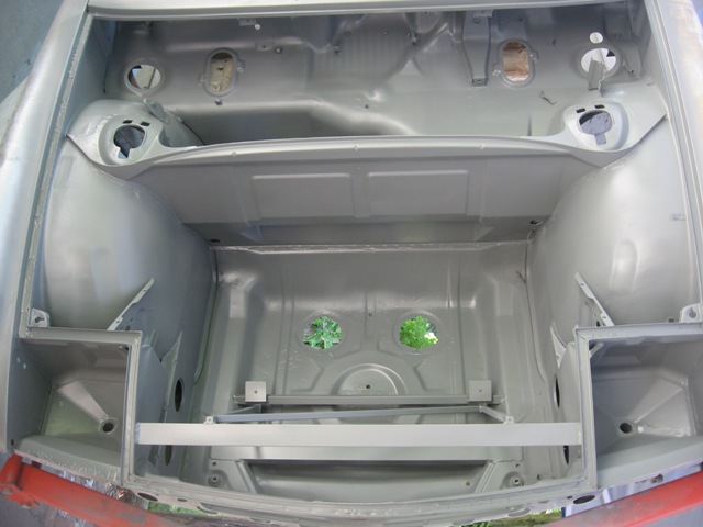
Next comes flare smoothing and epoxy primering, followed by wrapping up the interior metal prep/primer. Once that is done, I plan to pull the tub off the rotisserie so that I can assemble everything for final fitting of all components and testing. But for the rest of today, I'll sit in front of the boob-tube and relax in comfort (with the AC on!).
Posted by: arkitect Jul 13 2010, 05:11 AM
Geoff,
Great build thread!!!!
Alot of fabrication and attention to details, very impresive. Very interested in the work on the gas tank for cleaning and sealing...a little nervous about using a liner inside the tank that has the potential of coming off in the future but I've seen posts that they last for quite awhile. Might just try to neutralize the rust and do a good cleaning on mine.
Your car will be very clean when it's done from top to bottom, can't wait to see it.
Dave
Posted by: charliew Jul 13 2010, 12:09 PM
I have been using por 15 brand of tank sealer kits for more than ten years. If it's done right by the instructions it will last longer than the car. It is a inside shell of urethane. If you ever do one and inspect the amount that drains out and see what is is you will understand. Cleaning a tank will not stop future rust.
Posted by: Ductech Aug 24 2010, 06:51 PM
Hey now where is a good place to get that awesome chassis stand? That would make rustoration ten time easier!
Posted by: charliew Aug 24 2010, 09:22 PM
Most 914 guys use modified engine stands as a starting point.
Posted by: strawman Aug 24 2010, 09:43 PM
Most 914 guys use modified engine stands as a starting point.
Yupper, see post #27 of this thread for details on the rotisserie. I hope to have the tub off the rotisserie in the next two weeks... been working hard on the project, I just haven't taken time to update this blog.
Posted by: strawman Aug 25 2010, 11:06 PM
I haven't updated in a while, but I have been making process. The AA flares are finally on, and the welds are cleaned up. After finally getting a replacement driver side rear flare (still waiting for reimbursement ), I mated up the lower corners to match up with the factory "angular" sections. I also stripped the paint on the outer surfaces (chemical stripper, D/A sander and 80-grit sandpaper), cleaned the entire body using POR-15 Marine Clean, etched with POR-15 Metal Ready, and finished off with PPG two-part epoxy primer. These pics were taken tonight, so sorry for the crappy pictures.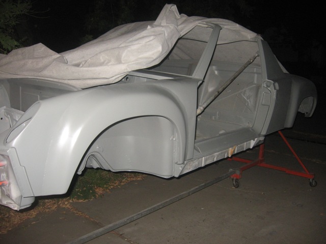
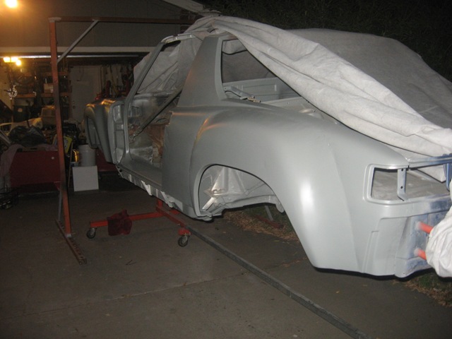
I need to finish up the area beneath sill plates and the outer rockers, and then I'll tackle the cab interior, the top portion of the windshield frame, and the inner portion of the targa bar. I'll address the front and rear areas when I take the tub off the rotisserie -- hopefully this weekend.
I also dug out the seam sealer in the inner fenderwells, addressed any rust issues (!) and cleaned/etched/epoxy primered those areas. You can see where the seam welding completed in the gas tank area and front trunk burned through nicely.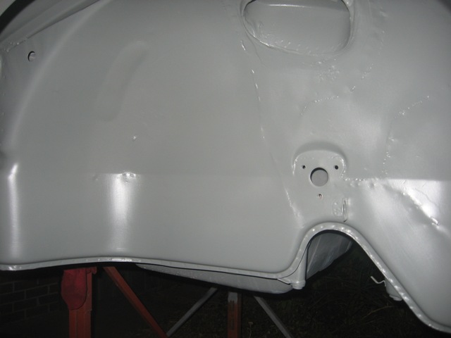
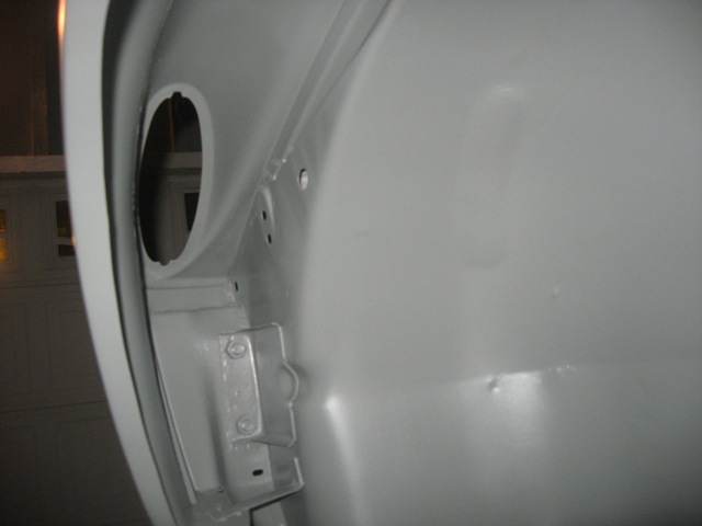
Posted by: strawman Aug 25 2010, 11:24 PM
I also finished up the "erector set" of the radiator inlet shroud. In total, this shroud required six pieces of 16 gauge aluminum. I bought some aluminum prep solution that will allow me to powder coat it; I'll post pics when that process is completed. I'll also assemble it on my bench so that you can see how intricate it is (I'm kinda proud, see).
By the way, I LOVE Clecos! They're kinda cumbersome, but they work really well for mock up. 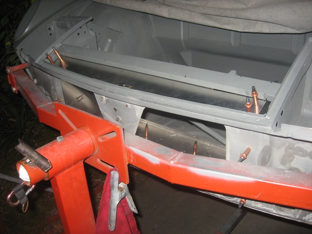
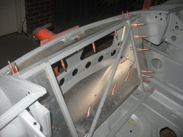
Here is a pic of the water-air intercooler heat exchanger that I'll be using. It is off a Ford Crown Vic, and I spent a LOT of time cleaning it...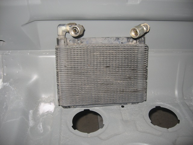
I also bought a Ground Control coilover setup for my Bilstein rear dampers, with 250 lb/in springs. Jay from Ground Control recommended these to match my 18.8mm front torsion bars, Elephant polybronze bushings, Tarrett front sway bar and camber plates. They're works of art; I'll post pics when I set these up.
Geoff
Posted by: charliew Aug 26 2010, 10:36 AM
Geoff great work. The fabbing is nice and the epoxy primer is good. I use it always, even as a thinned sealer coat. I do have a concern though about adhesion on it if it sets over 24 hours. The spec sheet I think I remember says it's a non-sanding primer which means I think it needs to be scuffed for the next coat if it goes past the 24 hr period. There may be a answer in just shooting a second coat of epoxy primer over it when the next stage of paint whether it's a sanding primer, seam sealer, filler or top coat is going to be applied. I think of it as a way to put the next coat on without needing to sand or scuff in all the little nooks and crannys so the next coat sticks real good. I've never had the desire to see if the top coats adhear well after it's cured a long time though, the later coats cost too much for me tp worry about whether they are going to peel or not, not counting the work to remove them. When I plan on putting filler over it I apply the filler before 12hours to try to get the best adhearance of the filler. I know you are trying to stop flashrust so this may be your only way to go but you might want to plan ahead on the interior areas where the next coat will only be a top coat and the nooks and crannys are hard to scuff.
You make like powdercoat but another approach on the aluminum panels is to bead blast them and shoot the ppg epoxy on them and then a top coat will stick really good. Also I'm not sure how the thin aluminum will be after it gets 400 degree powdercoat heat.
You are making great strides, keep it up.
Posted by: strawman Aug 26 2010, 01:32 PM
... The spec sheet I think I remember says it's a non-sanding primer which means I think it needs to be scuffed for the next coat if it goes past the 24 hr period...
Yup, I planned on scuffing the epoxy primer before the final topcoat. But I'm trying to stop rust from its relentless march onward while the tub sits outside. I'll check to see if another coat of epoxy primer right before topcoat or buildup primer will suffice; I just bought 1.5 gallons of the stuff, so I should have enough for a quick/thin spray of buildup primer after final body work. I've got more smoothing than I anticipated prior to stripping off the paint and bondo...
From what I've read, aluminum needs to be treated for flash "white rust" much sooner than steel -- like 10-15 minutes after scuffing/blasting. So I bought some Liquiguard PC AL Powder Coating Primer from Caswell to treat it after scuffing or bead blasting it. I'll do a sample powder coat on a leftover scrap piece to see if the aluminum warps. Thanks for the input...
Geoff
Posted by: charliew Aug 26 2010, 01:59 PM
If you use the primer for a sealer try to thin it with dt reducer and that will keep it thin and reduce the orange peel that will add to the top coat orange peel.
Posted by: Justinp71 Aug 26 2010, 09:35 PM
Looks awesome Geoff! Must feel good to have the body all ready to go. Can't wait to do some autocrossing with you.... Maybe next season?
Posted by: roadster fan Aug 26 2010, 11:25 PM
Holy !@#$ Geoff! I have been missing all these updates. Your progress and work look awesome. Keep it up!
When we are done we are both gonna have Phoenix Red Flared Frankenstein cars with water cooled motors........THE HORROR!
Jim
Posted by: strawman Sep 15 2010, 12:20 AM
As shown in the pics below, I have completed the air-to-water intercooler heat exchanger mounting, and wrapped up the mounting of the clutch master cylinder.
Here is a pic of the exchanger, which is actually an oil cooler that came out of a Ford Crown Vic. I'll be running 3/4" hoses back to the engine compartment, where a Bosch heater booster pump will ensure a good flow between the intercooler and the heat exchanger. 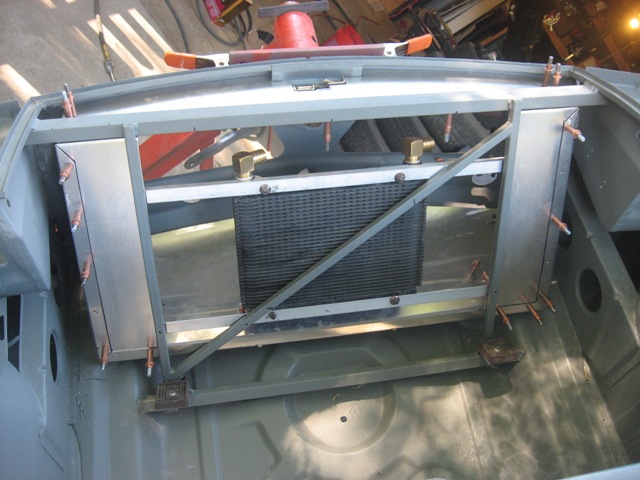
A good tip: the heater booster pump out of a mid-1990s BMW 5- or 7-series is the same unit used on the Ford Mustang Cobra that came with a factory air-water intercooler; tell the guy at the Pick-n-Pull counter that it is a "heater control valve" and you'll get it for under $10. You'll need a 6mm Allen wrench, 10mm socket, flat blade screwdriver and wire cutters (be sure to get the pigtail and the entire assembly so that it indeed looks like a heater valve!) and about 5 minutes to get one these. They're $100 new from various aftermarket vendors; I picked up four of them for under $40.
Next up are pics of the clutch master cylinder setup. This one came of of a 1993 Honda Civic hatchback, and has the same 5/8" bore as the one that came out of the Suby (a 1998 Forester)... so I'm confident it will mate up with the Suby clutch slave cylinder. The Suby unit has the reservoir incorporated into it, and it won't fit in the front bulkhead area; the Honda one uses a remote reservoir that I'll mount up by the stock 914 master cylinder reservoir. I built a custom "rod extender" to mate up the 914 pedals and the Honda master cylinder input shaft. Basically, I welded a 7mmx1.25 nut to a piece of 1/2" x 1.8" strap, and I'm using a 3/8" OD bronze bushing (which fits perfectly into the 914 clutch tab) over a 1/4" bolt that I welded to the strap to ensure smooth operation. The pictures don't show the outer bronze bushing/washer or the cotter pin that I'll add when I'm ready to install it "for reals." I've also included a pic of the brake and clutch master cylinders sitting comfortably side-by-side (the former is a 19mm unit from a 1976 911 that I scrapped, but I installed an ATE rebuild kit that I found on Ebay to freshen it up).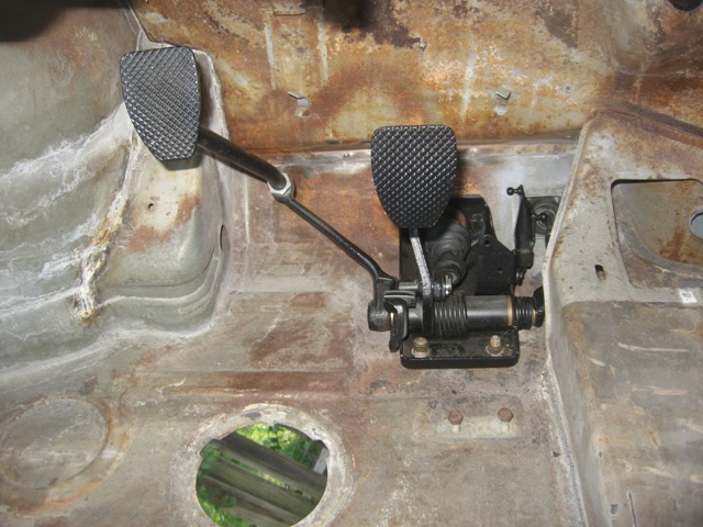
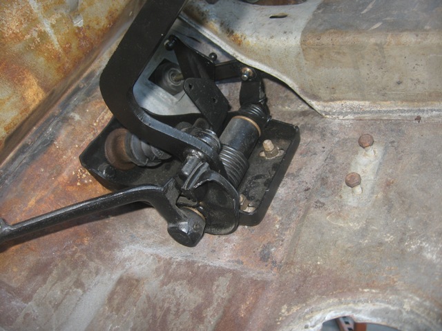
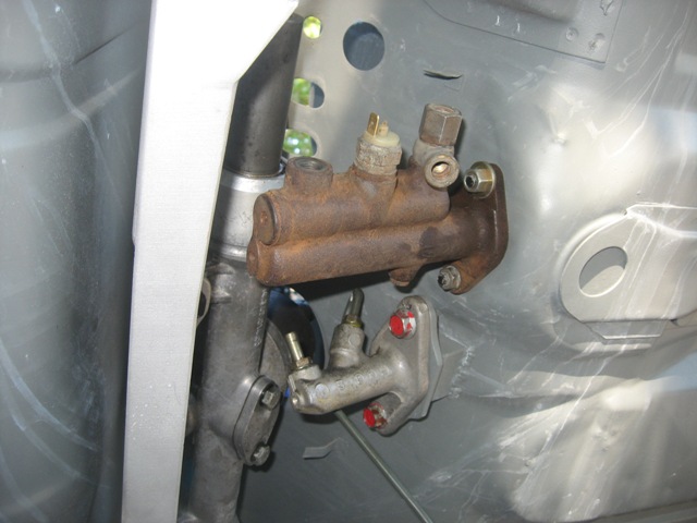
I still need to bend up and install the FedHill cunifer hardlines for the brakes and clutch systems, which I hope to mock up this weekend. I also hope to mock up the radiator and intercooler hoses. Stay tuned!
Posted by: Andyrew Sep 15 2010, 12:51 AM
VERY nifty clutch solution!!!
Will most likely use it! Thats been one of the area's of possible expensive purchase (cut off the stock clutch and use a racing pedal). But this is perfect!
Posted by: Britain Smith Sep 15 2010, 12:52 AM
Good tip on the heater booster pump.
-Britain
Posted by: charliew Sep 15 2010, 12:32 PM
Good ideas Geoff. I took me a little bit to undestand the original honda pushrod screws into the metric nut you welded to the strap for the final length adjustment. The pump is great info.
Posted by: strawman Oct 9 2010, 10:33 PM
I remember posting once that stripping the underside of the floor was the worst job ever... but I stand corrected. The worst job is stripping the interior of the tub. I probably spent 25 hours scraping, sanding, wire-brushing and spot sandblasting the remnants of the paint, glue and tar in there. PITA.
As always, I cleaned with Marine Clean, used Metal Prep to abate any remaining surface rust and then painted two coats of PPG two-part epoxy primer. Below are a couple of pics. I actually completed the primer work about two weeks ago, but I've been too busy with our 24 Hours of Lemons Opel GT project (Team Tinyvette) to post these pictures.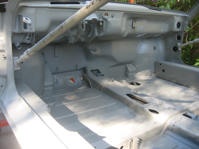
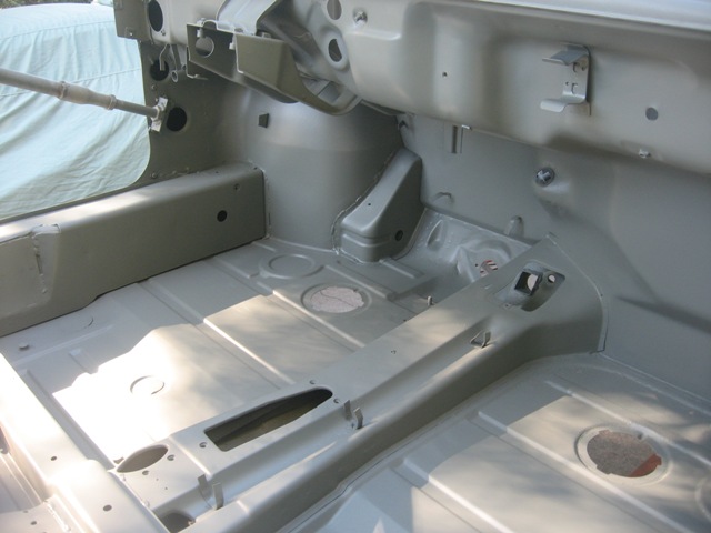
Next up is a close-up of the hydraulic clutch master cylinder area.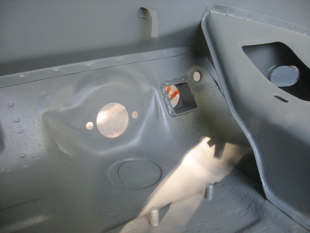
Posted by: strawman Oct 9 2010, 10:42 PM
The big news is that I've finally got the tub off the rotisserie and in its natural habitat (on jackstands!). My A-frame and cherry picker setup permitted me to lower the car slowly by myself, and the whole process went swimmingly. Here are a couple pics of the prep stage (before a burrito-n-beer).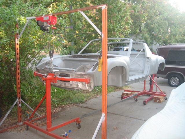
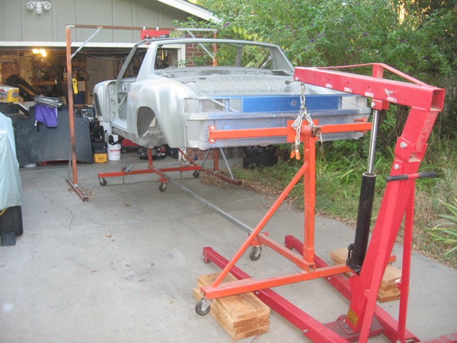
Here is the tub on the 'stands. Yeah, yeah I know -- these type of jackstands are unsafe. I plan to stick piece of wood in the "triangle" to prevent a complete deck-out; I'll look for the "correct" ones in the coming weeks and see if the War Department will free up the necessary cash...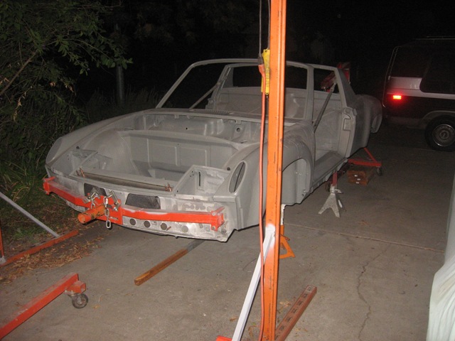
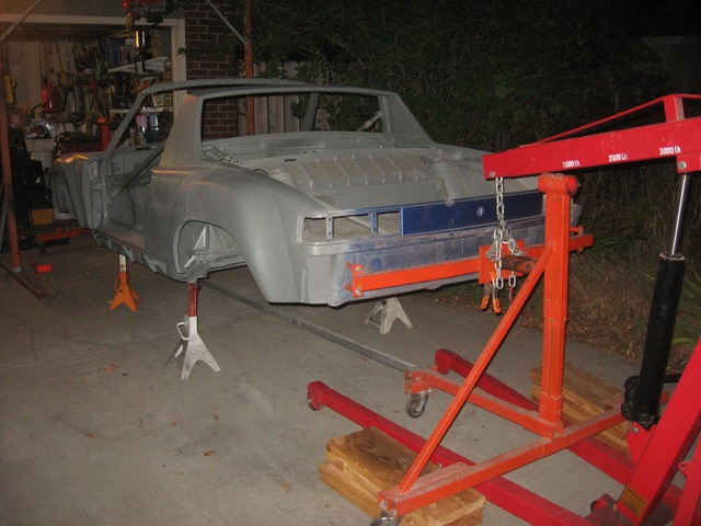
Did I set a record? My car was on the rotisserie for 27 months
My plan is to mock up all of the mechanical parts so that I can weld on tabs/mounts/brackets before I begin to tackle the aesthetics. I might even get it fully running to make sure everything is kosher before I commit to the final paint...
Posted by: Hontec Oct 10 2010, 03:42 AM
Wow, very nice progress and the car looks amazing!
Posted by: computers4kids Oct 10 2010, 08:24 AM
Geoff,
I'm loving your build, but most of all your ingenuity & graveyard finds. Seeing your tub makes me want to do another project...I just don't think I have it in me right now though.
Mark
Posted by: strawman Oct 27 2010, 09:38 PM
My teener is on the ground for the first time in over two years! I've put it on "roller skates" so that I can maneuver it easily while I begin the assembly process. Gotta say that I'm excited about this milestone!
It is obvious that I'll need to clearance the passenger side rear flare, as there is practically zero clearance between the lip and tire (junkyard 225/50-16 on 16x9 BBS wheels). Of course, once the engine/trans is in and the suspension is compressed, the camber might suck the top of the tires a bit. I haven't installed any shims yet, either. But there is more clearance on the driver side than the passenger side.
I've mocked up the fiberglass front hood and a spare rear hood, just for giggles. Stay tuned!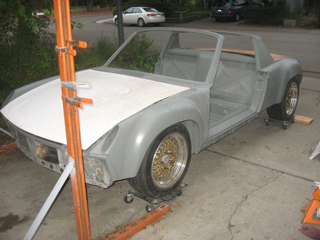
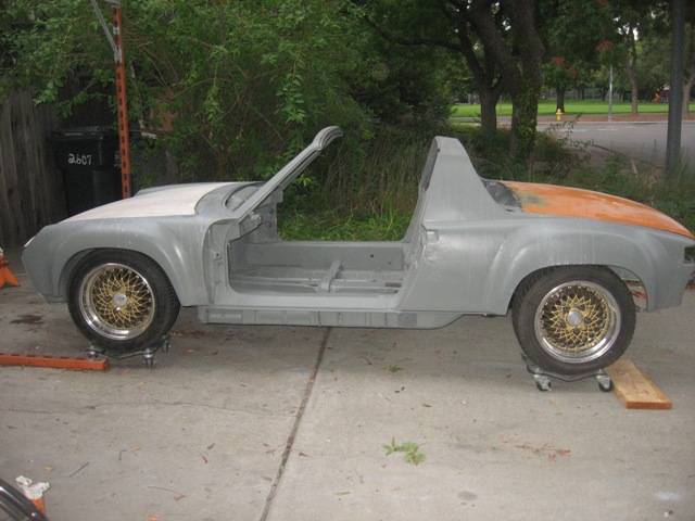
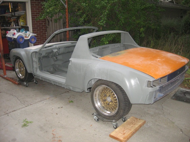
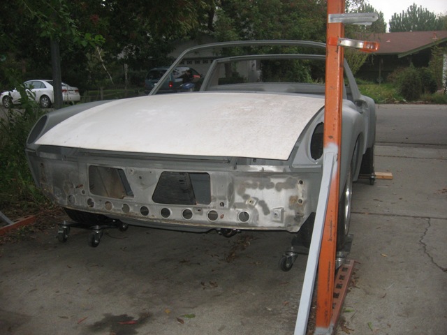
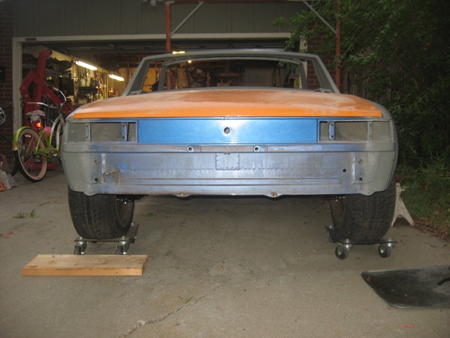
I love the final picture; reminds me of the immortal words of Sir Mix A Lot -- I Like Big Butts!
Posted by: arkitect Nov 7 2010, 08:25 AM
Geoff,
Missed your update, did a search on your build to see how you were doing. Glad to see it's off of the rotiesere. You do excellant work, great to see the progress. What color are you going with? ...and where and how much did you pay for the front fiberglass hood?
Dave
Posted by: strawman Nov 9 2010, 01:10 AM
Geoff,
Missed your update, did a search on your build to see how you were doing. Glad to see it's off of the rotiesere. You do excellant work, great to see the progress. What color are you going with? ...and where and how much did you pay for the front fiberglass hood?
Dave
Hi Dave, thanks for the compliments. I am a huge World Champion San Francisco Giants fan (man, that sounds great!), and I am hoping the Giants front office will share the CMYK or other color coding scheme for my own "tribute" orange-n-black car.
The fiberglass hood came with a crazy $50 deal that included a Saab wagon FULL of parts a while back on Craigslist. It is an A.I.R. unit and it needs some small 'glass repairs on the underside and at one rear corner, but it is uber light. The deal also included the orange rear steel hood shown in the pics and another steel front hood that I'll cut up as an experimental radiator air exhaust setup. I'm trying to avoid cutting holes in the front fenderwells...
Posted by: AgPete139 Nov 9 2010, 04:03 PM
Good job on your build.
I don't when I'll have a Saturday to do my tank, but when I do, I'll be referencing your Page 3. Looks great!
Posted by: strawman Nov 12 2010, 11:42 AM
When I welded the stiffening tubes in the trailing arms and moved the parking brake cable mounts (see post #98), I knew I would have to construct some parking brake cable extenders.
I ended up buying a couple stainless steel eye ends from West Marine that I crimped onto the leftover factory parking brake cables that I cut to length. The ends accept 1/8" cable, which is close enough to the factory cable outer diameter. West Marine permits you to use their cable cutters and cable end crimper on-site; see pics below for details. 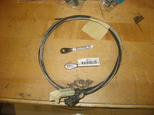
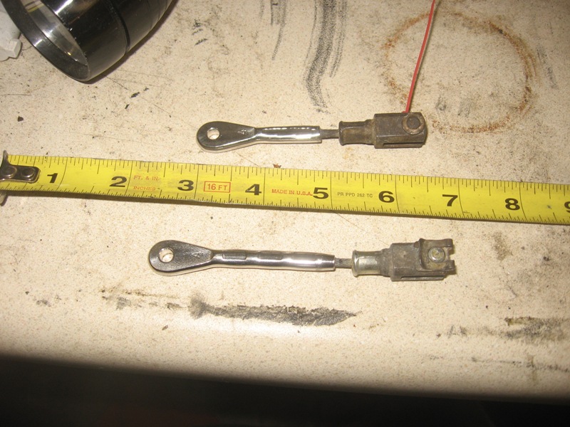
As you can see, I had to build two different cable extender lengths. I prolly coulda ended up with the same length extenders had I measured better when I welded on the cable mounts... 
I will open up the holes in the SS ends to match the factory pins, and then sandblast/powdercoat them in the coming days. I took today off and hope to button up the braking system; I'm in the process of bending up new lines right now. Stay tuned.
Posted by: strawman Nov 13 2010, 11:54 PM
Just finished up replacing ALL of the hard lines on my teener. Trivia: it takes 24 brake line nuts to replace them all, and roughly 22' of hard brake line (not including the lines and line nuts for the hydraulic clutch system). All told, I have one 30" piece leftover from the 25' roll of Cunifer brake line that I bought from FedHill. Since I adapted 911 rear brakes and lost a few of the factory hard brake lines, I ended using brazing rod to make templates for the custom and/or missing pieces. Below is a pic of the powdercoated proportioning valve and the copper-looking Cunifer line.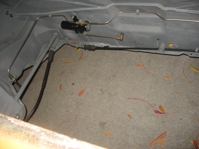
I like doing this type of work -- measuring, cutting, bending, flaring. It has a Zen-like quality, and it sure beats rust repair. Now I gotta bleed the whole brake system -- which I don't anticipate will have a Zen-like quality...
I also hooked up my steering system and finished off the parking brake system. Below is a pic of the parking brake cable and extender. It seems to work flawlessly, although I would probably build shorter extenders if I had to do it all over again -- probably 0.5" shorter on each side. Regardless, I can now sit on the floorboard, make engine noises and stop my rearward progress on my sloped driveway using the brake handle. 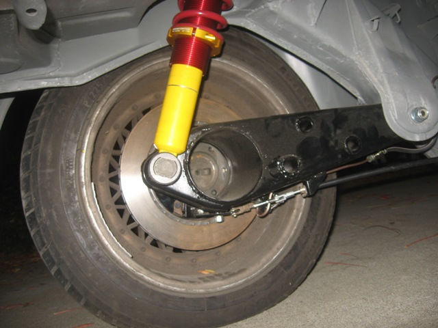
I hope to install the Suby engine & trans later this week so that I can measure the axle lengths and send the 911 axles off to be shortened & splined for the Suby inner CV joints. If my measurements were correct, the axle lengths should be the same on both sides, so I'll probably have one extra axle from my stash cut/splined as a spare.
Posted by: strawman Nov 14 2010, 08:17 PM
Alrighty then, I had a chance to work on the car today for a couple of hours. I was able to install the engine/trans, and to mock-up the axles.
As shown below, I built some boxes out of scrap 2x10 and plywood to rest the chassis on while I slide the engine under the tub. The home-built A-frame, and Harbor Freight electric hoist and 1000 lb. strap easily lift the engineless tub. These boxes are 19" tall and provide the 34" clearance necessary to roll the engine underneath on a homebuilt dolly. 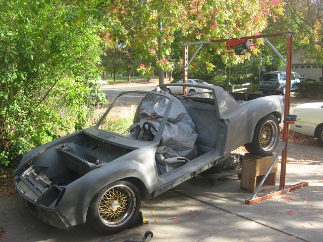
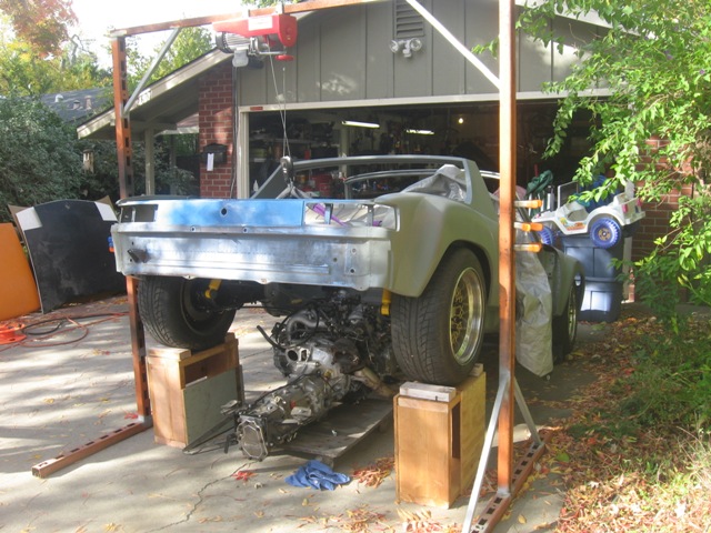
I found that I can not bolt up the engine U-bar until the engine is pulled up into the engine bay; otherwise the bar hits the rear trailing arms as I try to raise it. Once the engine dolly was slid underneath, I lowered the tub from the boxes to some standard ramps. Then I used the hoist on the engine and a floor jack on the transmission to lift it in place.
Here are a couple pics of the engine in the bay. It looks like there is plenty of space for my Vortex air-water intercooler and assorted plumbing.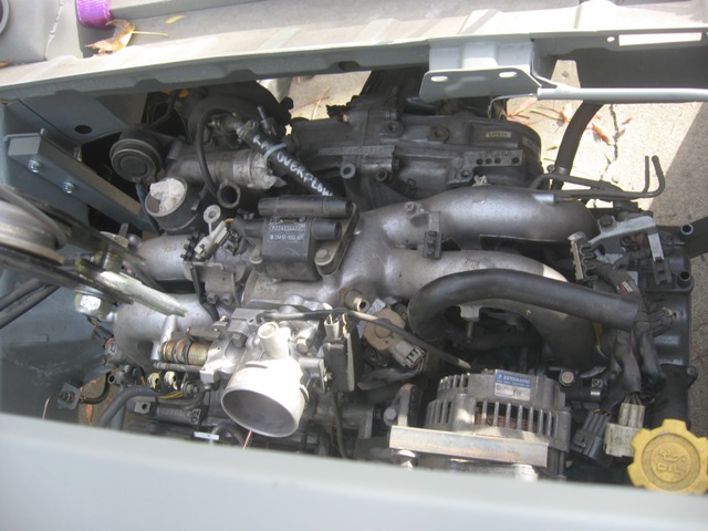
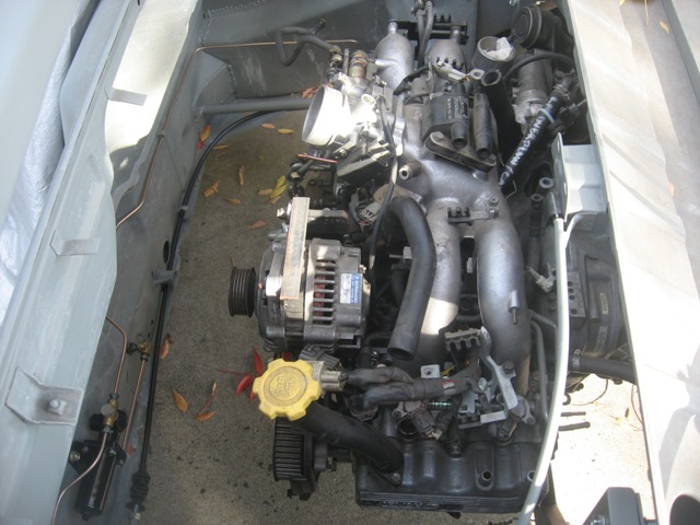
Posted by: strawman Nov 14 2010, 08:35 PM
I also had a chance to mock up the axles. First, I cut the inner end of a Subaru axle and the outer end off a Porsche 911 axle (actually, the splines are the same on both ends of P-axle). Then I slid the shortened Suby axle on the transaxle output and bolted up the Porsche shortened axle on the trailing arm hub. I then used a piece of scrap angle iron and two Vise-Grips to lock them in place, making sure they were centered in their range of travel and could still be removed. I then spot-welded everything together and re-tested for length; the good news is that this mock-up fits both sides perfectly. Once I confirmed that everything works, I welded the angle iron to the axles to get it ready for machining. The end-to-end length is exactly 18.5".
Here is a pic of the mocked up axle: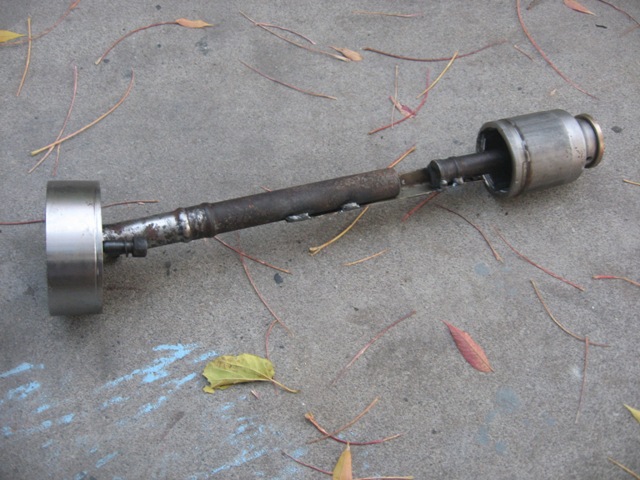
And here is a pic of the mocked up axle next to an uncut axle. I will send the mock-up and the remaining three axles off to get shortened & re-splined (that'll give me one spare axle). The SF Giants slippers are included for all of you baseball fans out there... 
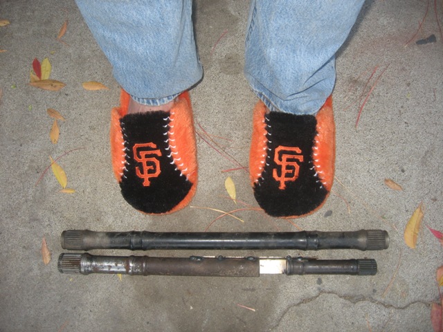
Posted by: BIGKAT_83 Nov 14 2010, 09:27 PM
Is your Subaru joint a tripod or a ball and socket type joint. The axles I did with the tri pod joint came in a inch shorter. Did you center the transaxle up with the swingarms or do you have the engine mounted farther foward for turbo. clearance???
Bob
Posted by: strawman Nov 14 2010, 10:56 PM
Is your Subaru joint a tripod or a ball and socket type joint. The axles I did with the tri pod joint came in a inch shorter. Did you center the transaxle up with the swingarms or do you have the engine mounted farther foward for turbo. clearance???
Bob
I am using the far more common ball/socket joint, which appears to still be used by the WRX cars. I picked up a larger diameter tri-pod jointed axle at a junkyard a few months ago (typically only found in 2wd Legacy cars), but the maximum OD of the tri-pod joint is larger than the minimum of the Porsche 911 axles that I have. So I am going with the slightly smaller ball/socket joints. If these prove to be troublesome, I suppose I can go to custom axles with the larger tri-pod joints in the future.
EMPI sells replacement ball/socket and tri-pod joints. I downloaded the EMPI pdf catalog with these parts numbers; you can download a copy here:
http://www.empius.com/cvjoints.html.
Geoff
Posted by: BIGKAT_83 Nov 15 2010, 09:23 AM
Is your Subaru joint a tripod or a ball and socket type joint. The axles I did with the tri pod joint came in a inch shorter. Did you center the transaxle up with the swingarms or do you have the engine mounted farther foward for turbo. clearance???
Bob
I am using the far more common ball/socket joint, which appears to still be used by the WRX cars. I picked up a larger diameter tri-pod jointed axle at a junkyard a few months ago (typically only found in 2wd Legacy cars), but the maximum OD of the tri-pod joint is larger than the minimum of the Porsche 911 axles that I have. So I am going with the slightly smaller ball/socket joints. If these prove to be troublesome, I suppose I can go to custom axles with the larger tri-pod joints in the future.
EMPI sells replacement ball/socket and tri-pod joints. I downloaded the EMPI pdf catalog with these parts numbers; you can download a copy here:
http://www.empius.com/cvjoints.html.
Geoff
My transaxle is from a 2005 wrx and included the axles. These were a male stub tri-pod type that goes into the transaxle on the CV joint end. I think there is 6/7 different axles that can be used. I saw some axles on a closeout on rockauto and ordered these for the CV joints and they came as large ball and socket type. I'm going to have another set of axles made for someone and use these.
I've driven my car about a 1000miles now and have been very pleased with the transaxle. I even did a 5000 rpm drop the clutch power lanch to see what would happen....
Bob.......speed shiftin like a ricer
Posted by: strawman Nov 15 2010, 10:33 AM
My transaxle is from a 2005 wrx and included the axles. These were a male stub tri-pod type that goes into the transaxle on the CV joint end. I think there is 6/7 different axles that can be used. I saw some axles on a closeout on rockauto and ordered these for the CV joints and they came as large ball and socket type. I'm going to have another set of axles made for someone and use these.
I've driven my car about a 1000miles now and have been very pleased with the transaxle. I even did a 5000 rpm drop the clutch power lanch to see what would happen....
Bob.......speed shiftin like a ricer
I need the female-type CV joints, as I'm using an OBX limited slip differential that has male outputs. Good to hear the transaxle has the oomph to take a 5000 rpm clutch drop!
Posted by: charliew Nov 19 2010, 11:59 PM
My email with msn has been so slow I haven't been around for awhile. What is the tire patch size that did the 5k clutch dump? Kinda curious as to how much traction was applied to the tranny. 7,8,or 9 inch tires?
Posted by: Zaney Dec 20 2010, 02:07 PM
As shown in the pics below, I have completed the air-to-water intercooler heat exchanger mounting, and wrapped up the mounting of the clutch master cylinder.
Here is a pic of the exchanger, which is actually an oil cooler that came out of a Ford Mustang. I'll be running 3/4" hoses back to the engine compartment, where a Bosch heater booster pump will ensure a good flow between the intercooler and the heat exchanger.
A good tip: the heater booster pump out of a mid-1990s BMW 5- or 7-series is the same unit used on the Ford Mustang Cobra that came with a factory air-water intercooler; tell the guy at the Pick-n-Pull counter that it is a "heater control valve" and you'll get it for under $10. You'll need a 6mm Allen wrench, 10mm socket, flat blade screwdriver and wire cutters (be sure to get the pigtail and the entire assembly so that it indeed looks like a heater valve!) and about 5 minutes to get one these. They're $100 new from various aftermarket vendors; I picked up four of them for under $40.
Next up are pics of the clutch master cylinder setup. This one came of of a 1993 Honda Civic hatchback, and has the same 5/8" bore as the one that came out of the Suby (a 1998 Forester)... so I'm confident it will mate up with the Suby clutch slave cylinder. The Suby unit has the reservoir incorporated into it, and it won't fit in the front bulkhead area; the Honda one uses a remote reservoir that I'll mount up by the stock 914 master cylinder reservoir. I built a custom "rod extender" to mate up the 914 pedals and the Honda master cylinder input shaft. Basically, I welded a 7mmx1.25 nut to a piece of 1/2" x 1.8" strap, and I'm using a 3/8" OD bronze bushing (which fits perfectly into the 914 clutch tab) over a 1/4" bolt that I welded to the strap to ensure smooth operation. The pictures don't show the outer bronze bushing/washer or the cotter pin that I'll add when I'm ready to install it "for reals." I've also included a pic of the brake and clutch master cylinders sitting comfortably side-by-side (the former is a 19mm unit from a 1976 911 that I scrapped, but I installed an ATE rebuild kit that I found on Ebay to freshen it up).
I still need to bend up and install the FedHill cunifer hardlines for the brakes and clutch systems, which I hope to mock up this weekend. I also hope to mock up the radiator and intercooler hoses. Stay tuned!
Anymore progress on this awesome clutch setup?
Especially the connecting strap portion.
Thanks,
Nate
Posted by: sawtooth Feb 4 2011, 01:04 PM
Okay, so I just got another cocktail, and thought I'd take the time to add some more details of the trans teardown.
First up is a pic of the trans on my workbench, with the rear and mid case removed. As noted, you can see the Bremar coupler. You can also see one of the two trans side covers that provide the side-side adjustment of the differential/ring gear to get a good pinion / ring gear pattern.
Here is a pic of the mid case draining out the nasty-smelling gear oil. As part of the Bremar FWD conversion, you toss the rear case & guts, which originally housed the center differential. The shift rod is also shown in this pic.
Next is a pic of the guts of the trans.
Here is a side-by-side of the factory diff and the OBX limited slip.
Geoff, your suby trans rebuild is awesome, now that I'm thinking about a rebuild on mine I just went back and re-read this. Thanks for taking the time to get pics. I have a '93 5spd from non-turbo legacy in my car now and so far it's great, but I believe it needs some new bearings on the main shaft. My plan is to just pick up another and rebuild it to swap in at a later time. I would like to do the same as you, bearings, seals and the obx lsd. Can I ask where you bought your OBX? I see them listed on ebay for the '02-'06 wrx trans, but nothing for earlier years, non-wrx. I read somewhere the obx lsd should fit any suby 5spd trans but wanted to double check with someone who has done it. Also did you find a kit for your bearings and seals or did you just buy the individual pieces?
Thanks,
Dean
Posted by: strawman Feb 4 2011, 05:54 PM
Sorry I haven't updated the thread in a while... too damn busy to even work on the teener much lately.
The OBX lsd is the same for all 5-speed pre-2006 transaxles, if memory serves. I bought mine on Ebay from a guy that provided the best price. He currently has the same price as when I bought mine http://cgi.ebay.com/ebaymotors/OBX-LSD-Differential-02-06-Subaru-Impreza-WRX-FWD-/170436213159?pt=Motors_Car_Truck_Parts_Accessories&hash=item27aeca39a7.
Some guys on the NASIOC say you should replace the OBX case bolts with higher-grade bolts before you install it (D'oh! I read that too late), while other guys say it is a waste of time/money. My car is still not running, so I can't say if that is sage advice...
I've been watching your car build -- keep up the good work!
Posted by: strawman Mar 19 2011, 04:48 PM
Been a while, and life's been in the way too much lately. But I've been able to work on a few things...
Below are some pics of the Suby Alternator/AC compressor mount that I modified to move the alternator toward the driver's side of the motor to allow 180 degree rotation of the intake manifold. I welded on ears to mount the alternator, and the belt lined up with the outer grooves on the crank pulley. Even though I hacked off a bunch of metal from this mount, it is still really heavy -- but it looks nicer after I powdercoated it and it should be rock solid.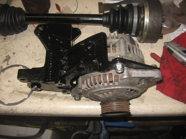
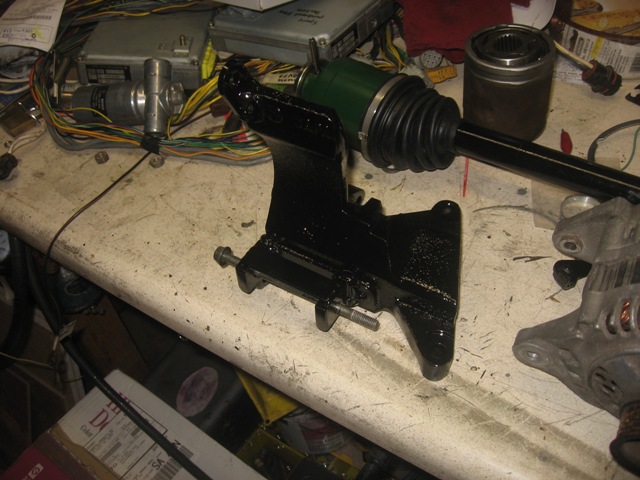
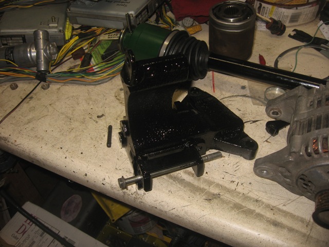
I also rebuilt and powdercoated a spare pedal set. Here it is mounted alongside the new gas pedal from Mikey914. You can also see the powedercoated (but dusty) mount I built to raise the MR2 shifter.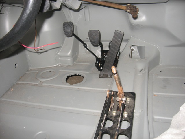
The 911 axles that were shortened and resplined on one end by Dutchman Axles are in. You can see one of them on the workbench in the pictures above; they're comprised of cleaned/repacked 108mm 911 outer CVs and cleaned/repacked Suby Legacy Turbo inner CVs. I'll take a picture of the axles and post it here later. The SS fuel line from Tangerine are also in, and the modified fuel tank is mocked up, too. I hope to install the alternator, oil pump, water pump and cam belt/tensioners tomorrow. I'll then mock up the water hoses and finish up the fuel system in the coming days.
Posted by: strawman Jun 19 2011, 09:49 PM
Haven't had time to update this thread in a while, but I have been squeezing in some time here and there. Also, my family gave me most of day in the garage today for Father's Day!
I found that the Vortech water-air intercooler won't work without some crazy hose routing, so I bought a Type 13 water-air intercooler from FrozenBoost as well as some aluminum tubing, silicone hoses & reducers, and t-bolt clamps. In all, that stuff ran about $275. Below is a picture of this work-in-progress. There's just enough room underneath for the air intake/MAF routing, but it is tight. I'll be running a plastic radiator fill-cap system from a Kawasaki Ninja 250 (it has 3/4" hose bibs to match my intercooler coolant system), as well as an electric Bosch water heater recirculation pump from a 5-Series or 7-Series BMW. If you pick one of these up, tell them it is a Heater Control Valve and you'll get it for less than $10; I picked up four of them over the past couple months to have spares.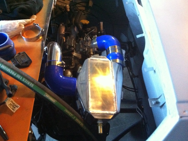
I also finished up the front routing of the coolant hoses and IC hoses to the front of the car. I'm using 1.25" wired hardwall rubber Marine Exhaust hose to bring the chilled coolant from the radiator back to the engine, and 1" diameter to run the hot H2O from the engine to the radiator. It is a very tight squeeze to get the hoses over the top of the front aluminum suspension and under the steering rack (especially for the larger 1.25" hose), but this arrangement really maximizes ground clearance IMHO. As you'll see in the pic below, all of the hoses go through holes I cut in the front firewall. I picked up heavy-duty grommets online from Fastenal.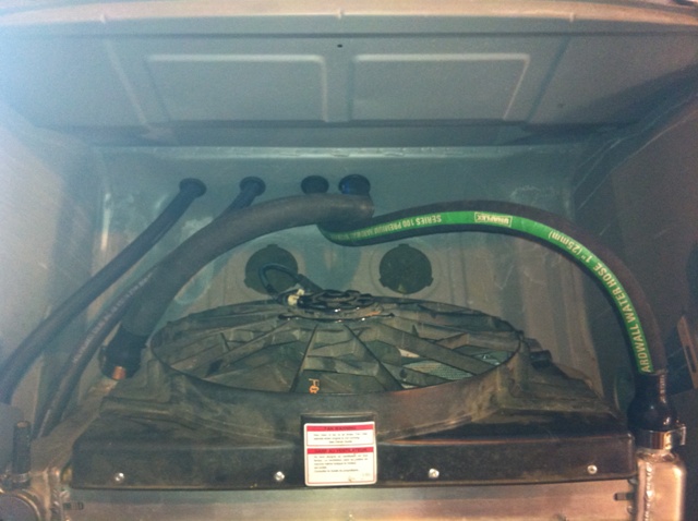
I'm using Gates 3/4" heater hose to/from the front-mounted heat exchanger and the IC. You'll see the routing in the picture below. You'll note that I haven't removed the rust and epoxy painted the front of the car yet; that area (and the rear of the car) were obscured by the rotisserie mounting bars. Something that is on my list of things to do...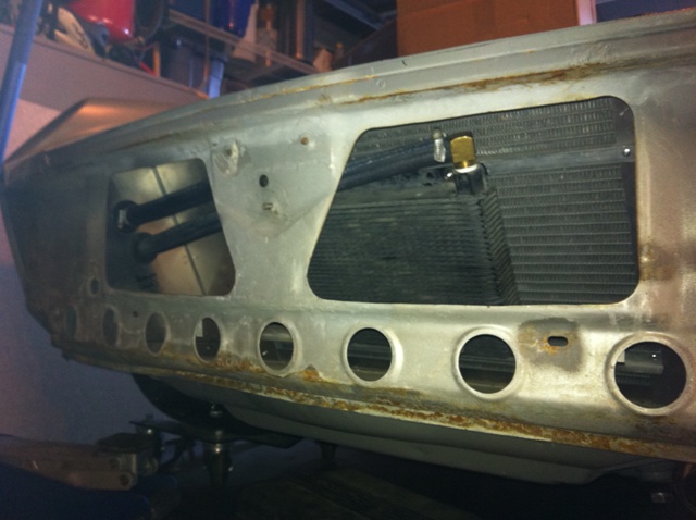
Posted by: kg6dxn Jun 19 2011, 09:59 PM
Awesome! I love air to water intercoolers. Frozen Boost has some cool stuff. I'm doing the same crap to mine but I'm using a Boxster or NACA duct in the rear quarters for fresh air.
Posted by: Britain Smith Jun 19 2011, 10:01 PM
You gonna have it done by Thursday to bring it to the WCR
Just joking, looks good! I got my icebox from Frozen Boost.
-Britain
Posted by: strawman Jun 19 2011, 10:16 PM
My good buddy's family took off for LegoLand in San Diego for week, but he didn't want to leave the keys to his Boxster in the house for his 18 y.o. daughter to do dumb things with  So he told her he gave me the keys to do some maintenance on it
I wanted to see how his 17" wheels would fit and look on my car, so I took some time to investigate. The fronts are 205-50-17 on 17"x7" wheels with ET of 55. The rears are 255-40-17 on 17"x8.5" wheels with ET of 48. My wheels are BBS three-piecers in 16"x7" and 16"x9" with 205-50-16 and 225-50-16 (junk) tires. The Boxster wheel/tire combos are 39/46 lbs (F/R), while the BBS combos are 32/36 lbs. The diameters of the Boxster wheels are 25"/24.5" (F/R), while the BBS are 24"/24.5".
Below are some pics. First is my BBS rear tire/wheel, showing how little clearance exists between the tire and the flare lip. No spacers are used with my BBS wheels, nor is the alignment likely to be close to good. But there is a LOT of clearance between the tire and inner fender well -- on the order of 1" on the driver side and 1-3/8" on the passenger side.
Next up is the rear Boxster wheel mounted, followed by a pic of the rear inner clearance. All of the Boxster wheels were mounted using factory Porsche 944 spacers, which are about 3/4" thick.
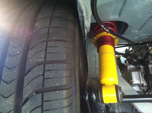
Obviously, the tire to inner fender well clearance is too tight -- I cannot even fit my pinkie finger up there. No camber shims are mounted up right now, so camber is maximized.
Finally, here is the Boxster front wheel mounted up (again, with a 3/4" spacer) -- which is about perfect in terms of clearance with these wheels. 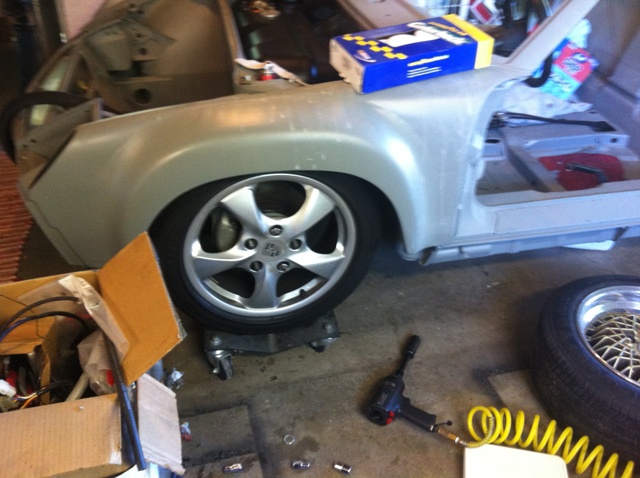
As you all know, it is getting harder and harder to find good 16" performance tires (much less period correct 15" tires). So I might look for some Boxster wheels and try to sell my BBS rims to a 930 enthusiast. What do you guys think?
Posted by: kg6dxn Jun 19 2011, 10:25 PM
Big O has some good 16's. I think your BBS look cool! I would paint the centers black if they were on my car. I have chrome ATEV's on mine. I've been thinking of a change but can't decide.
Posted by: strawman Jun 20 2011, 12:17 AM
Britain, YEAH RIGHT! I wish I had the time to even give it a try! But work gets in the way, and my boss retired last month -- they gave me his job with only a small stipend increase. Gotta love workin' fo' da gubment!!! Either way, I'll be at WCR and can't wait to see your car. Hope my new camera doesn't burn out (hence the crappy Iphone pics above) snapping pics and stealing ideas 
Mike, I love the look of my BBS wheels and planned to powdercoat the centers black. But the offset on the rears is a little off, unless I machine the centers down to move 'em inboard a bit or find some different barrels. I'll need to talk to Al or Harvey Weidman to see what my options are.
Posted by: z31turbo Jun 20 2011, 10:09 AM
Very impressive build, keep up the good work 
JF
Posted by: pktzygt Jun 22 2011, 01:46 PM
I wonder how well the frozen boost heat exchanger and fan would if you put it in the rear of the car. I was thinking about a canister style muffler on one side and the heat exchanger on the other side. I can't imagine it would be any worse than the air to air intercooler.
Why did you turn the intake manifold? Just for ease of plumbing? I have the renegade mount, but want to avoid using their intercooler mess (there must be 6 feet of piping).
I also have a hot rod air system that I plan on installing. I think the intercooler heat exchanger, condenser and radiator in that little space might over-do it.
Posted by: strawman Jun 22 2011, 06:48 PM
I wonder how well the frozen boost heat exchanger and fan would if you put it in the rear of the car. I was thinking about a canister style muffler on one side and the heat exchanger on the other side. I can't imagine it would be any worse than the air to air intercooler.
Why did you turn the intake manifold? Just for ease of plumbing? I have the renegade mount, but want to avoid using their intercooler mess (there must be 6 feet of piping).
I also have a hot rod air system that I plan on installing. I think the intercooler heat exchanger, condenser and radiator in that little space might over-do it.
Not sure about the heat exchanger in the engine compartment; I'd imagine you'd have to use auxiliary fans to cool it. Interesting idea, though. With that setup, I wonder if you'd take up so much "high" real estate in the engine compartment with the air/water intercooler and heat exchanger that it'd be a bear to get to any upper engine components from the top / engine lid. But I like the way you're thinking...
Yes, I turned the intake around for ease of plumbing. In hindsight, it definitely would've been easier to cut into the rear trunk... but I'm already losing so much of the front trunk with the radiator and hoses that I wanted to have some semblance of storage space in the rear trunk.
I might try to put A/C in my car someday, as it gets HOT here in the CA Central Valley. At this point, however, I'm just trying to get my car ready to roll on its own!!
Posted by: pktzygt Jun 23 2011, 05:06 AM
Not sure about the heat exchanger in the engine compartment; I'd imagine you'd have to use auxiliary fans to cool it. Interesting idea, though. With that setup, I wonder if you'd take up so much "high" real estate in the engine compartment with the air/water intercooler and heat exchanger that it'd be a bear to get to any upper engine components from the top / engine lid. But I like the way you're thinking...
Yes, I turned the intake around for ease of plumbing. In hindsight, it definitely would've been easier to cut into the rear trunk... but I'm already losing so much of the front trunk with the radiator and hoses that I wanted to have some semblance of storage space in the rear trunk.
I might try to put A/C in my car someday, as it gets HOT here in the CA Central Valley. At this point, however, I'm just trying to get my car ready to roll on its own!!
I was thinking way back by the muffler and would have to use the aux fan for sure. Your engine must be sitting farther forward than mine. I was thinking about putting the intercooler on the passenger side top similar to where renegade puts it. and it would need two 90 degree bends to the throttle body and a couple other bends from the turbo inlet.
As of now the frozen boost 350hp kit or the 600hp kit are what I'm thinking about. It would depend on how much space is under the rear. I could probably do without that heat shield and free up some space.
You car is looking great by the way. Thanks.
Posted by: charliew Jun 23 2011, 10:46 AM
The pictures of the boxter wheels are great. I have almost those exact wheels and tires but the rears I have are et 50's. I really appreciate the info, it will help alot on the fitment. I actually like the bbs better as far as looks but maybe it's because those are like the factory wheels on my gt fieros.
No matter what heat exchanger used it will only be as good as the air temp moved through it. The front is WAY better than the rear.
Posted by: pktzygt Jun 23 2011, 07:13 PM
The pictures of the boxter wheels are great. I have almost those exact wheels and tires but the rears I have are et 50's. I really appreciate the info, it will help alot on the fitment. I actually like the bbs better as far as looks but maybe it's because those are like the factory wheels on my gt fieros.
No matter what heat exchanger used it will only be as good as the air temp moved through it. The front is WAY better than the rear.
I know, I know I was just trying to convince myself a pusher fan might do the job for something like an intercooler. Radiator, NO! I'll probably just give it a shot and let you know how it works. The worst thing that could happen is I have to move it.
OK, I'll stop Hijacking your thread now, Sorry.
Posted by: kg6dxn Jun 23 2011, 10:35 PM
I know, I know I was just trying to convince myself a pusher fan might do the job for something like an intercooler.
Pusher fans are never, ever as good as a puller through a radiator. It's like trying to push a rope. doesn't work.
I'm putting my heat exchanger in the rear quarter panel. I'm ducting with either a Boxster side vent or a NACA duct. I also have to fab an inner fender skirt to keep rocks and mud from clogging the radiator.
I need to go
Posted by: Heater Guy Jun 24 2011, 02:44 PM
I have a subaru 914 SCCA track car and planning to replace the 901 transaxle with the Subaru trans axle.
If you have a few minutes to give me some info. I would surely appreciate it.
Ron Randolph
Walnut Creek, CA
(925) 945-8178
Posted by: charliew Jun 24 2011, 03:43 PM
I've siad this story before but I'll try and repeat it as well as I remember it. My son hot rods a 04 sti. we made a cold air intake to isolate the intake air to the turbo from the underhood heat. This is a watercooled motor that runs at about 205. It already had a front mount ic. We used a thermocouple at the throttle body and the aircleaner. The thermocouple reader would only do one at a time so we made two passes in 4th gear. WE ran the wires into the cabin and I would switch the wires on the terminals. It was about 98 degrees ambient at 6pm that evening. It might have been hotter right above the pavement. The temp at the throttlebody was 4-5 degrees hotter than the temp at the aircleaner. Actually at one point it said 104. The cold air intake was getting air from inside the inner front fender which is also connected to inside the front bumper and from the hood scoop.
Posted by: strawman Jul 21 2011, 11:23 PM
As is normal, I've slacked on updating this build blog... but I've made some good progress.
I've completed the installation of the cooling lines and all connections except one final one to the radiator (vendor sent one incorrect 90* silicone reduce elbow). I am using 1" internal-wire marine hose from the engine outlet (top of engine) to the radiator, with a reducer elbow connecting to the 1.5" radiator inlet. I am also using 1.25" internal-wire marine from the radiator to engine inlet (bottom of engine at thermostat housing); this requires a 1.75" to 1.25" reducer elbow to mate up to the radiator outlet. I used Adel clamps to secure the hoses in the recesses on the bottom of the tub.
First up is a better picture of the frunk (note the lower radiator hose is not connected -- waiting for the correct elbow to be shipped!).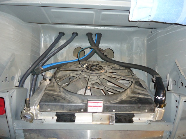
I still have to finish the upper radiator mounts. You'll see the two rubber blocks (Kragen rubber coil spring boosters, part number 18-1701, $7.99), which I'll trim down to fit in the recess on the top of the radiator. Those will be mounted to the metal bracket marked "Dr" that I welded up and will be bolted to the threaded holes on the top of the crossbar.
Next up is the picture of the underbody hose routing. Because of the stainless wire in the hose, you need to cut the hose using a thin abrasive wheel; I used a 3" cutter in a die grinder.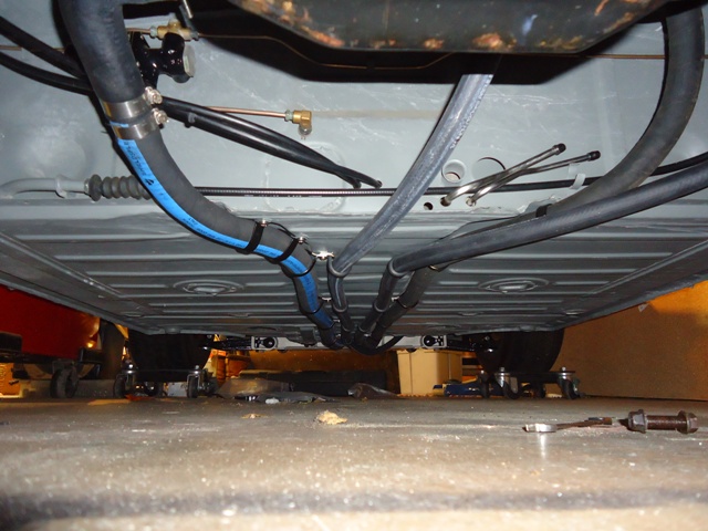
As you can see in the two pictures above, I also finalized the 0.75" air-to-water intercooler hose connections. Again, I used Adel clamps to secure these hoses to the bottom of the car, which I've routed between the two engine coolant hoses. I still need to finalize securing those two hoses at the front of the car and in the engine bay.
Below is a picture of the air-to-water filler neck (from a Kawasaki 250). You really don't NEED an overflow for an A-W intercooler, as the temps never get high enough to expand the water, so I'll block of that port. The filler is mounted to a bracket that I welded to the area above the factory battery mounting area. The pump is rubber mounted to a small bracket that I welded to the upper long. 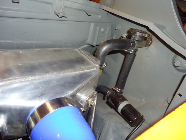
Finally, here is a picture of the engine bay with the air-water intercooler and all turbo piping installed. I welded up stand-off mounts using 3/16" rod, which I'll powdercoat after I finish up mounts for the fuel lines, wiring, etc. I still need to finish up the MAF, air cleaner and related piping/mounts.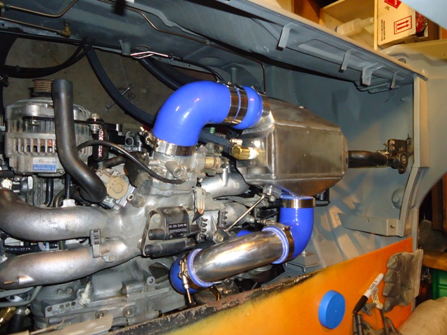
Posted by: strawman Jul 21 2011, 11:37 PM
Here is a picture turbo exhaust outlet, which shows the clearance provided by the "box" I welded in the rear trunk floor for the turbo, starter and clutch slave cylinder. It is hard to tell from the photo, but there's about 2.5" clearance above the hot-side of the turbo.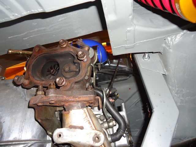
The next few pics show how anal I can be at times...
I am using the stock and HEAVY cast iron exhaust manifolds, at least in the beginning. A lot of the guys on NASIOC complain about SS headers cracking, and how only the stock manifolds can stand up to long-term abuse. Grimmspeed sells ported/polished cast iron manifolds, so I thought I'd give it a go myself 'cause I'm a CSOB.
As you can see below in a couple "before" pics, there are some pretty gnarly welds near the flanges of the uppipe. The cast pieces also have some slag and casting marks that could hinder the flow of air to the turbo. What you see below is about four hours' of using a carbide ball bit, stone grinders and a sandpaper roll port-n-polish kit from Harbor Freight. Not sure if it will really make a difference, but I suppose every little bit helps 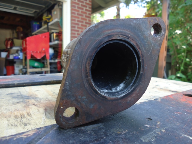
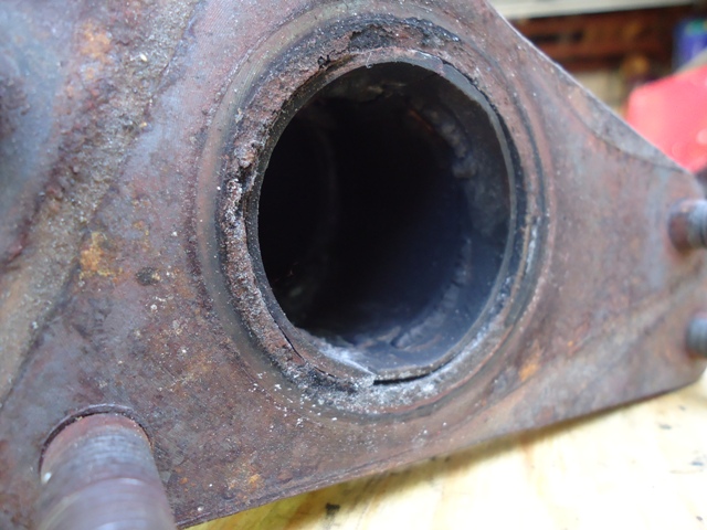
Posted by: strawman Jul 21 2011, 11:49 PM
Here are a couple "after" photos. 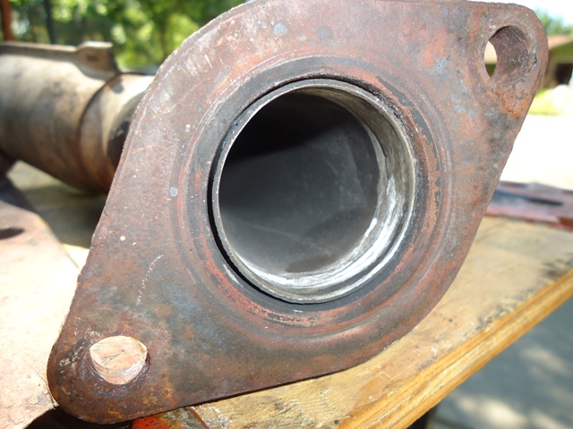
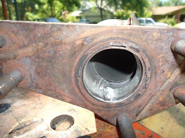
Those were ground down using a carbide ball bit & stone; those will be polished using the port-n-polish rolls (at least I think I bought the kit from HF...). The picture below shows what the final product looks like.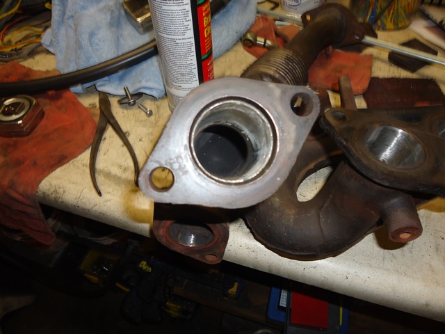
Posted by: sawtooth Jul 22 2011, 12:39 AM
Looking good.
Posted by: strawman Nov 6 2011, 07:36 PM
Wow, it has been 3 months since my last posting. I guess I really am a slacker...
I finalized my steering setup, which includes raised-spindle Bilstein struts with a lower arm welded on so that I could reduce the tie-rod angle to avoid bumpsteer. I am using 14mm Class 12.9 allen bolts, and found that .750"OD DOM tubing has an ID of .560 -- which works perfectly. I cut some spacers on a lathe that will be mounted above and below the tie-rod end. I will powdercoat the spacers later this week. The tie-rod end was supplied by Elephant Racing, and is a high-quality Aurora heim joint that is extra-long; off-the-shelf ones are too short and would result in extreme toe-in. Below is a pic of all the pieces for one side.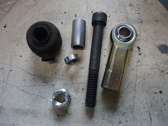
Here is a picture of the setup without the rubber boot, which I bought from a supplier in England. The pic following shows the setup with the boot and upper/lower washers. I still need to drill the allen bolts for a cotter key to use with the castle nut.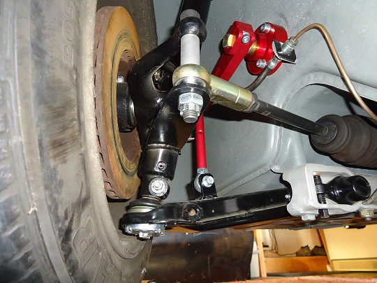
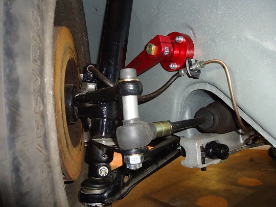
Posted by: charliew Nov 7 2011, 07:57 AM
Looks good Geoff. I guess the arc of the lower a arm moving up is what makes a longer tierod end necessary. How much more travel upward does the a arm have at this setting?
Posted by: strawman Nov 7 2011, 02:20 PM
Looks good Geoff. I guess the arc of the lower a arm moving up is what makes a longer tierod end necessary. How much more travel upward does the a arm have at this setting?
Actually, I believe a longer tie-rod end is necessary due to the angle of the hole in the factory steering arm -- it points toward the outside/rear of the car and not directly straight down. Elephant sells the longer heim joint for their raised-spindle setup (mine is homebrewed) for that same reason.
The travel should be the same as factory, since the strut and A-arm sits in the same relative verticle position. Raising the spindle on the strut body essentially moves the center of the wheel up (and the car down = lowered) without affecting the suspension geometry. See posts #84 and #93 to see details of how I raised the spindles a little more than one inch.
When you use the factory torsion bar adjusters to lower the car, you're changing the angle of the A-arms (relative to the ground), which also exacerbates the tie-rod angles and increases bumpsteer problems. My admittedly copied setup eliminates those problems.
Posted by: strawman Jun 19 2012, 09:50 AM
Finally, we closed on our new-to-us house in San Luis Obispo and I was able to pull my teener out of storage. Below is a pic of the car on the HUGE equipment trailer I rented (U-Haul couldn't find me a regular car transport within 100 miles!) at the storage facility, and the second shows it sitting proudly in her new home.
It has been over six months since I've laid hands on her... I think I now know what it feels like to be a sailor coming home to his lovely wife after a long stint on the sea! 
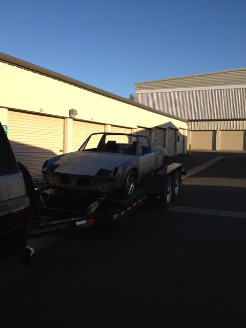
Let the fun begin!
Geoff
Posted by: JRust Jun 19 2012, 09:54 AM
Congrats on the new place Geoff! Nice to see the teener out of storage too. I can see progress coming much quicker for you now. It's great to be able to run out to the shop for even just a few minutes. Alot easier to get things done when the shop is at your home . Get over moving all your stuff & get to work 
Posted by: Zaney Jun 19 2012, 07:01 PM
Hooray!
I am so glad that you have finally found a place for your Teener!
I am trying to use the John Kelly fender stretching techniques to make my wheels fit. i hope that your new digs suit your family well!!!!
Cheers!
Nate
Posted by: ThePaintedMan Aug 10 2012, 09:31 AM
Geoff,
Sorry I hadn't commented on this thread previously. Your work is a thing of beauty. I hope to have the resources one day to do a car "right" like you are. One of the main questions I've always had about Subaru conversions is the gauges. What are you planning to do in this area? Is there any way to preserve the functionality of the tachometer, and alt/fuel gauges in particular? If I was ever to attempt something like this, I would probably keep the 901 transaxle, so the speedo wouldn't be an issue.
Posted by: strawman Aug 11 2012, 08:41 PM
One of the main questions I've always had about Subaru conversions is the gauges. What are you planning to do in this area? Is there any way to preserve the functionality of the tachometer, and alt/fuel gauges in particular?
I am hoping the signal from the Subaru ECU will drive the 914 tachometer, and I plan to obtain an electronic 911 speedo and see if a two-wire Subaru Vehicle Speed Sensor will work. The e-VSS from 1997 & 1998 Forester fits right into the older 5-speed Suby transaxles like mine, replacing the mechanical speedometer drive. I'm eager to find out if it will work, too!
Posted by: kg6dxn Aug 11 2012, 09:21 PM
Is it done yet?
Posted by: strawman Aug 11 2012, 09:29 PM
Finally, I had some time to work on my car -- after about 8 months of inactivity.
I spent some time several months ago (!) poring over the wiring diagrams of my 914 and the donor car -- a 1993 Subaru Legacy Turbo -- to chronicle which Suby wires should mate to which 914 wires, and vice versa. I put this into a spreadsheet if anyone is interested.
It should be noted that many ECU wires are shielded and are a bitch to alter the length. I figure the Fuji Heavy Industries engineers were prolly a little particular when it came to signal loss, so I decided to place the ECU in a place where no shielded wires had to be lengthened (see pics below), and will loop the ones that are too long. Not as pretty as would be possible if I were willing to risk chopping those shielded cables, but this strategy should avoid some gremlins during the shakedown.
Another thing that seems to be a best-practice is to solder wires where possible, followed by a good two-wall heat-shrink (with silicon goop inside!). I've read you should unplug from the ECU to make sure no weird signals are sent upstream, so I did that, too. For those large wires (i.e., 12 gauge or larger), I use either weatherproof crimp connectors ($$) or just use bare crimp barrels followed by good heat-shrink. Where there is a possibility that the wires might face extreme vibration or other stress, I double the heat-shrink. Maybe I'm being too paranoid and over-engineering things, but this has worked for other engine swaps I've completed in the past. Furthermore, I work in the public transit world, and the good buses are built using those practices, while the ones I overpay towing companies to haul back to our shop use the cheap non-weatherproof connections that make my mechanics pull their hair out. 'Nuff said...
This isn't merely a mating of two harnesses; that would be too easy. So you have to improvise and plan for what you're trying to accomplish. For example, I ran an 8 gauge wire through the 914 loom from the battery to the radiator fan controller in the front trunk, as well as a couple of other new wires I knew I'd need (vehicle speed sensor for an electronic speedo, in-tank fuel pump, etc.). I also know that I cannot envision what other electronic items I might add in the future. So I ended up running five extra 16 gauge wires from the engine bay to the fuse box area (with an extra 5' at the fuse box end), as well as one extra 14 gauge wire from the engine bay to the front trunk. I have a small hill of wires I cut out of the Suby harness and the 914 harness. I recommend keeping every wire you remove, since you might need them later to have a same-color splice as you progress in this type of project. I also used a Delco Weatherpack system that will permit me to remove stuff without cutting wires in the future. I'll show a close-up of the 6-port system I used later on.
The first picture shows how everything is laid-out, as well the copious amount of marking I use to make sure I'm hooking up the correct wires (measure twice, cut once, check again, then connect). I like to use high-quality green or blue masking tape and a Sharpie to signify where it comes from on one side and where it goes to on the other side. Do yourself a favor and use scissors to trim the tape tags -- if you leave 'em ragged they'll catch on stuff and end up falling off. You can also see the small Braille battery I'm running. I thought about mounting it low on the cabin-engine bay firewall, but I'd have to run a long (and relatively heavy) cable back to the starter -- so I figured I'd keep it close to the ECU where it is easily accessible. As you can see, I'm running the wires through the targa top cup holes; I still hafta figure out grommets to protect the looms.
The second picture shows the cabin area, prior to mounting the updated fuse-panel or running the loom through the front firewall to the front trunk. You can see the big-ass red 8-gauge radiator fan wire coiled up on the driver's seat, as well as the 14ga blue wire for the fuel pump / spare 14ga black wires for the frunk coiled next to it. You can also see the extra five wires draped over the door. Technicolor spaghetti love, eh?
The third picture shows the connections made from the Suby ECU/engine loom mated up to the 914 loom. Doesn't look like much, but there is easily 15 hours of head-scratching and pinched-ass labor between pictures 1 & 3.
The fourth picture shows the driver's area taking shape, after feeding the loom through the front firewall into the frunk. You'll note that I screwed up and neglected to feed the engine loom through the first tunnel hole (next to the shifter setup) -- that'll have to do until I tear it all apart again to paint it in the (hopefully near!) future.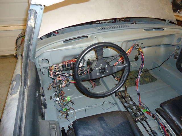
The final picture shows the Weatherpack system all sealed up. It requires some specialized tools, and the 18 and 20 gauge wires are a beeyotch to get right. But it is an OEM quality connection.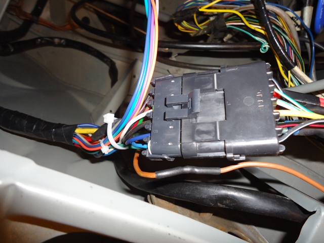
I still need to mount a few electrical components in the trunks, and to finalize the vacuum tubing. I could not fit the electronic HKS boost controller (thanks Jim Dupree!) wiring loom into the 914 wiring loom and still get it through the tunnel/firewall hole, so I'm gonna hafta drill through the cabin-engine bay firewall for that 8-wire loom. Then comes the exhaust system and final cabin wiring that will permit to start it up for the first time. Yay!
Posted by: 76-914 Aug 12 2012, 12:11 PM
Great thread. I'm sure I will be reading it again. Yes, I would be interested in a copy of the spread sheet you came up with, please. I was going to ask you if the shoulder of those allen bolts carried through until I read what you do for a leaving. Never mind.  I'm thinking A/C also so I'll be curious as to which system you employ.
Posted by: strawman Aug 12 2012, 01:15 PM
Attached is a PDF of the Suby-914 wiring spreadsheet if anyone is interested. Hope this works... Wiring_harness__Suby_Legacy_Touring_to_Porsche_914_11_Aug_2012.pdf ( 19.32k )
Number of downloads: 313
Wiring_harness__Suby_Legacy_Touring_to_Porsche_914_11_Aug_2012.pdf ( 19.32k )
Number of downloads: 313
If you have trouble opening it or if you'd like it in an MS Excel format, PM me your email addy.
Posted by: strawman Sep 24 2012, 09:05 PM
Wiring cuts/pastes are finally done; now I need to hook up everything forward of the firewall. In the meantime, I finalized my exhaust. I picked-up a stainless steel Invidia divided-bellmouth dumptube from a guy on Craigslist that went off-roading in his WRX by accident. The bottom was crushed-in, but I only needed the bellmouth and a few inches of the downtube -- so it was $20 well spent. I also picked up a mandrel-bent J-bend Pypes stainless steel piece from Jeg's and a shorty stainless Flowmaster (p.n. 843015) muffler to finish out the system.
Here is the bellmouth that shows the divide. I am using an internal wastegate that blows the over-boost from my TD05-16G turbo into the dumptube.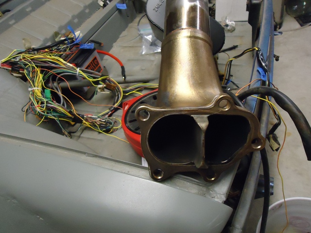
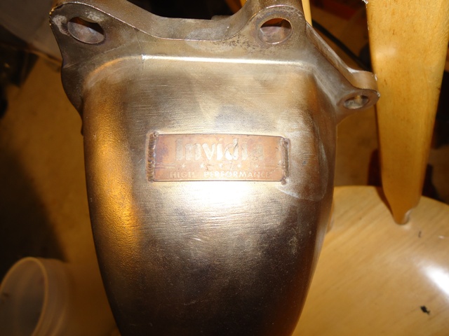
Next up are a couple pics of the exhaust mocked up. After a bunch of careful measurements and a few cuts, below is what I ended up with. My neighbor has a nice TIG machine, so he tacked it up for me after I marked & taped (!!) everything together. 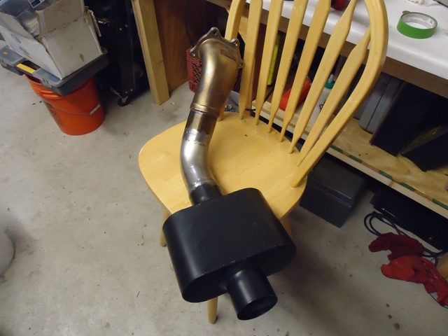
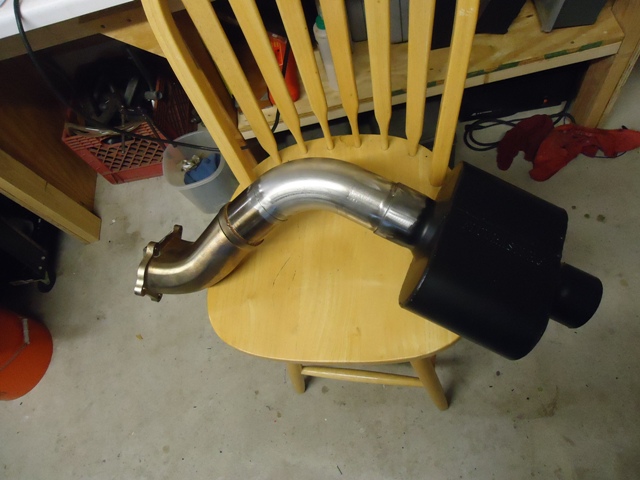
Here it is bolted in and tucked-up out of harm's way. Still need to devise a muffler support and an outlet tip. For the former, I'll bolt the muffler support to the transaxle, since the whole engine/trans/exhaust will move as a single unit in the engine/trans mounts.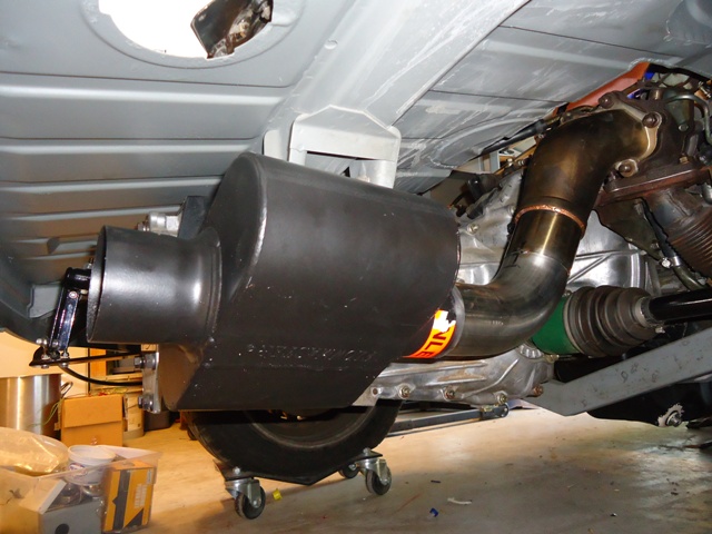
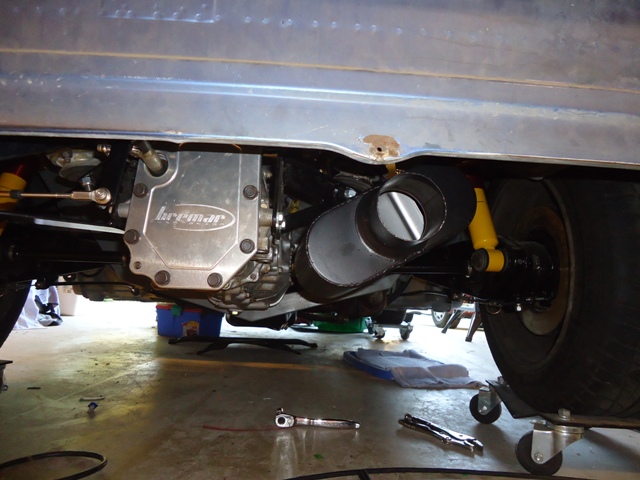
I still need to cut-in two sensor bungs -- one for the stock narrow-band oxygen sensor and one for a wideband sensor. I've somehow lost the two SS sensor bungs during my move, so I'll order a couple more tonight. Once I get them mocked-up, I'll walk it over to Bill so he can do his TIG magic...
Posted by: strawman Sep 24 2012, 09:13 PM
One other item that I finally finished up is a homebrew Fuel Cut Defencer. The stock Subaru ECU cuts the fuel at ~12 psi of turbo boost. Since I'm running an HKS electronic boost controller, I don't want the ECU to shut down the fuel when I crank up the boost -- instant piston meltdown. Basically, this system tricks the ECU into thinking the boost -- and therefore the maximum 5V signal from the sensor -- is at an acceptable level. Some call it a clamp, and it is mounted between the boost sensor and the ECU. Either way, I've got about $10 in this setup, saved myself about $75 and got to play with more electronic stuff. 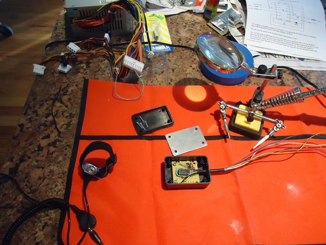
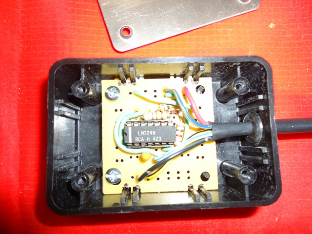
Posted by: kg6dxn Sep 24 2012, 09:15 PM
That muffler looks like it will be loud!
Posted by: strawman Sep 24 2012, 10:23 PM
That muffler looks like it will be loud!
Yup, the Flowmaster description says it will be "aggressive." I'm hoping the turbo will quiet things a bit but if I find it is too loud, I'll cross that bridge then. But I first gotta get it running. Keep up the great progress on your 1.8T project!
Posted by: Zaney Sep 25 2012, 12:08 AM
That muffler looks like it will be loud!
Loud pipes save lives!
Looks awesome, Geoff!
Posted by: strawman Nov 10 2012, 07:06 PM
After weeks of troubleshooting, testing & re-testing of fuel injection components and wiring, I finally realized that I had my fuel inlet/outlet lines backwards.  Swapped 'em, and it roared to life!
Of course, I immediately discovered some small coolant leaks and I've got my spare ECU mocked up for now, so I've got plenty of tidying up to do.
I've uploaded a video to Youtube from my iPhone, but it isn't fully processed yet. I'll update the link once it is up. But in the meantime
Posted by: strawman Nov 10 2012, 07:10 PM
Okay, I just checked and the video is now up-n-ready. You can see and hear it at:
https://www.youtube.com/watch?v=bO48RltUNBk
Just figured out how to embed it...
Posted by: FL 000 Nov 10 2012, 07:48 PM
Sounds pretty mean! It's a great feeling firing an engine up for the first time. Congrats
Posted by: strawman Nov 11 2012, 10:46 PM
Looks like I need to rebuild the turbo, as it is pushing oil into the turbine side and smoking like a mosquito control truck. I'm using a Mitsubishi TD05H-16G, which was used on late 1990's Subaru WRX engines in Europe and Japan. I'll take some pics of the rebuild when the kit arrives later this week. Supposedly good for up to 350hp.
I was able to eliminate the coolant leaks and tidy up some of the wiring today. This is getting fun again!
Posted by: biosurfer1 Nov 11 2012, 10:53 PM
Thats quite the rat's nest of wires you got there...glad to hear you got it running, maybe a WCR 2013 debut???
Posted by: ruby914 Nov 11 2012, 11:05 PM
After weeks of troubleshooting, testing & re-testing of fuel injection components and wiring, I finally realized that I had my fuel inlet/outlet lines backwards.
Swapped 'em, and it roared to life! Of course, I immediately discovered some small coolant leaks and I've got my spare ECU mocked up for now, so I've got plenty of tidying up to do.
I've uploaded a video to Youtube from my iPhone, but it isn't fully processed yet. I'll update the link once it is up. But in the meantime
Funny, on my Suby, after weeks of troubleshooting, testing & re-testing of fuel injection components and wiring, I finally realized I was out of gas.
It runs, that's a good feeling
next step Cool, I have to read more when I get home from work.
Posted by: McMark Nov 11 2012, 11:06 PM
Sweeeeeeeeet!
What about a oil line restriction? Is it a ball bearing turbo?
Posted by: strawman Nov 12 2012, 09:51 AM
What about a oil line restriction? Is it a ball bearing turbo?
Nope, the turbo uses two brass journal-type bearings, and has two rubber o-rings and two spring steel seals to control oil. The kit is ~$100, so it is not so bad. But before I remove the turbo I'll pull the exhaust manifolds to see if there's any oil pooled there; maybe my valve seals are bad from sitting so long...
Posted by: strawman Nov 12 2012, 09:56 AM
Thats quite the rat's nest of wires you got there...glad to hear you got it running, maybe a WCR 2013 debut???
Yeah, I completely "un-loomed" my formerly beautiful wiring setup so that I could trace each wire when I couldn't get it running
Boy did I feel stupid when I realized my fuel lines were backwards!The plan has always been to debut it at WCR (2010, 2011, 2012...). Hopefully WCR 2013 will be the one.
Posted by: my928s4 Nov 12 2012, 10:10 AM
Yeah, I completely "un-loomed" my formerly beautiful wiring setup so that I could trace each wire when I couldn't get it running
Boy did I feel stupid when I realized my fuel lines were backwards!Hey congrats on getting it running! I got the fuel lines backwards also ....
Posted by: charliew Nov 12 2012, 10:23 AM
Geoff also there is a chance the rings are stuck in the pistons from setting. Just run it for awhile to see if things loosen up and it might clean itself up. When I got my jhots 96 legacy outback tt motor I read up after checking the oil and finding it very black and burned smelling and read that a lot of owners didn't change the oil like they should knowing they wouldn't be keeping the motor long enough to justify the expense. The motor I have uses hydraulic lifters and they sometimes are stuck and won't pump up without a dissassembly and cleaning. The 96 motor has a oil restricter in the head where the banjo fitting is to the turbo oil line. It looks to be about .065
Your motor sounds great though. There should be a restricter in the oil line to the turbo. I think it's in the fitting where the oil line goes on but can't really remember right now.
I can hear my son's sti coming from about a 1/4 mile away. It sorta sounds like a helicopter from a distance when it is at low rpms.
Also you might want to check to see if the intake tract is oily, maybe at the throttle body hose connection. The ic could get a lot of oil in it. Run it na forawhile to see if the rings loosen up.
Posted by: 914GTSTI Nov 12 2012, 04:04 PM
Hello,looking to do the same trans in my 914. What did it cost to use the sube to 914 axles?
Posted by: kg6dxn Nov 12 2012, 07:08 PM
Awesome progress!
Now I got to catch up...
Posted by: strawman Nov 13 2012, 08:21 PM
Hello,looking to do the same trans in my 914. What did it cost to use the sube to 914 axles?
I used my 1976 911 axle shafts that I had laying around, shortened and re-splined by http://www.dutchmanaxles.com/index.php/services. See post #188 of this build blog for details. If memory serves, Dutchman charged me ~$150 to machine the pair of axle shafts that I sent them.
Posted by: strawman Nov 13 2012, 08:30 PM
Turns out the turbo is not pumping oil -- at least not into the intake side, since it is bone-dry. However, in my haste to get the engine running, I mickey-moused the PCV system. The PCV hose from the crankcase vent into the PCV valve on the intake manifold is SOAKED with oil and my spark plugs are now oil-fouled.  At least I didn't fill my A-W intercooler with oil!
I'm correcting the PCV system now, including re-hashing the piping to the oil catch can. I'll need to get two aluminum nipples TIG'd onto a 90 degree aluminum intake pipe to finish it -- hopefully later this week. Already put new spark plugs in. I'll post a higher-resolution video once I clean this thing up and eliminate its mosquito-smoke antics...
Posted by: 76-914 Nov 14 2012, 09:54 AM
Posted by: strawman Nov 18 2012, 12:14 AM
Got a chance to correctly set up the PCV system, using two oil catch cans -- one between the crankcase vent and the PCV valve, and another between the crankcase vent and the intake tract (before the throttle body). I also ran a hose from the head vents through a filter to the intake tract. I had a local welding shop TIG two nipples to the underside of the aluminum intake tract piping. For the most part, I was able to route the hoses underneath the intercooler and piping, but you can see a few of them in the video below.
To clean out the oil slick caused by my initial PCV system error, I ran half a bottle of Seafoam through the vacuum ports on the intake. Smoke galore, but along with new spark plugs the engine now purrs cleanly. Now I just need to figure out the cold engine start hunting/coughing; could be the larger than stock injectors I'm running, which will take a while for the ECU to "learn." I need to modulate the throttle for the first 20 seconds or so until it smooths out.
I was also able to finalize burping air from the cooling system. The radiator fan I'm using -- out of a mid-90s Lincoln Mark VII -- really moves a lot of air, so I'm hoping my cooling system will suffice. And the Bosch intercooler pump -- out of a mid-90s BMW 5-series (E34 chassis) heater booster system -- helps to noticeably lower intake temps, at least at idle. The alloy pipe coming out of the turbo is warm/hot to the touch, but the intercooler outlet is ice cold. I'm hoping to drive it in the cul-de-sac tomorrow or the next few days, if it will ever stop raining!
Here's a another video:
https://www.youtube.com/watch?v=RgzxVT6A7Tk
Posted by: charliew Nov 18 2012, 06:25 AM
Pvc is pretty complicated on a boosted suby. The vaccum in the intake manifold when it's na then the boost and a slight vaccum in front of the turbo reverses the pvc operation. Sometimes just longer hoses will help smooth out the high vaccum instances where the oil gets in the intake. We installed a mann provent ( it was used on the turbo, I think calloway, corvettes at one time) on my son's suby but it's a diesel part so the orings went to crap and needed to be switched but it puts the oil back in the pan to keep from lowering the oil level. On a low mileage driven car the catch cans are probably a easier and cheaper solution. I was afraid that the catchcans being a closed system sorta that the hoses would need to be extra long. We did a lot of plumbing with some manifolding to try to get a good system but now my son is considering going just to catchcans. I can't decide if this application is in the race car or street car application on the pvc deal.
Hope you come up with a better, simpler working solution than ours as the mann provent is not cheap.
Posted by: jsconst Nov 18 2012, 09:01 AM
That's got to be a great feeling to have it running after so much work.
I'm sure you can't wait for that first drive
Glad you got it going, can't wait to see it
Jeff
Posted by: Zaney Nov 19 2012, 06:07 PM
Don't worry about unraveling the wiring loom few times. I think I did it 6 times 
Great job Geoff!
Posted by: strawman Dec 31 2012, 07:27 PM
Drove it for the first time a few minutes ago, and my wife captured it on her iPhone. She's almost as excited as I was!
https://www.youtube.com/watch?v=bg_NjmUrk-o
Spent the day clearancing the fender flares, as I had a little rub under compression. Then I buttoned up the suspension (finally installed zip-ties that tie the rear upper hats to the Eibach coilovers) and torqued everything down. Finally, I installed the tach converter that Larry (904SVO) corrected for me  -- so I now have a working tach that is driven by the Subaru ECU.
The car definitely has a BIG turbo punch, although I didn't wanna piss off my neighbors too much. I still have a long way to go to have it truly roadworthy, but it feels GREAT to finally get it move under its own power!!!
Posted by: a914622 Dec 31 2012, 07:42 PM
Lucky page 13 as we go into 2013! congrads.
It sounds like the wife is happier! 
Posted by: 904svo Dec 31 2012, 08:56 PM
Glad that the tach works now. Did you wire the ODB2 in? check and see if you have any DTC codes I can help you with. Just wait till you get 18lbs of boost
and really go like HELL!!!!!!!!
Posted by: scotty b Dec 31 2012, 09:02 PM
That cul-de-sac looks like it is begging for some rubber rings 
Posted by: JRust Dec 31 2012, 09:06 PM
Drove it for the first time a few minutes ago, and my wife captured it on her iPhone. She's almost as excited as I was!
The car definitely has a BIG turbo punch, although I didn't wanna piss off my neighbors too much. I still have a long way to go to have it truly roadworthy, but it feels GREAT to finally get it move under its own power!!!
Congrats Geoff! Absolutely killer 
Posted by: kg6dxn Dec 31 2012, 11:31 PM
Awesome!!!
Posted by: wingnut86 Dec 31 2012, 11:50 PM
AWESOMENESS!!
Posted by: KELTY360 Jan 1 2013, 01:45 AM
Sounds badass!
HAPPY NEW YEAR!
Posted by: 76-914 Jan 1 2013, 06:54 AM
Let's see, I've read your build thread how many times and for som,ew reason thought it was already running. Mucho congratrulations.
Posted by: d914 Jan 1 2013, 09:15 AM
Awesome and congratulations,,, I though you were making me look really bad until I heard ur wife say 4 years into it!!
I'm working on five so I see light at the end of the tunnel..... Sounds sweet..
Greg
Posted by: ruby914 Jan 1 2013, 10:16 AM
Congratulations!
That is a great way to start the year.
Posted by: charliew Jan 1 2013, 11:51 AM
It sounds good, thats got to be a great feeling. I'm sure it gives you new energy for a couple more years of up grades. Just think how much closer to finished you are though.
Posted by: RobW Jan 1 2013, 12:03 PM
All the trick build and time spent pales in comparison to how you EVER got you wife that excited and supportive of a habit that clogs up the garage, burns your vacation time, and spends any cash, which will eventaully strand you around town, and cost as much as a foofy 911.
Congrats again though! AWESOME!
Posted by: d914 Jan 1 2013, 02:46 PM
I'll have to second that on the wife's reaction..... That was great to hear!
Posted by: Chris H. Jan 1 2013, 07:06 PM
Sounds AWESOME!!!! Good for you man, your hard work is paying off!
Posted by: biosurfer1 Jan 1 2013, 09:33 PM
Finally! WCR here you come!! 
Posted by: 914GTSTI Jan 4 2013, 08:59 PM
Very cool! And well done!
Posted by: Zaney Jan 5 2013, 12:08 AM
Congrats Geoff!!!
Hope to see some low altitude fly-bys soon!
Nate
Posted by: strawman Jan 27 2013, 02:23 AM
Finally got some time to work on my car. I installed a gauge cluster from a 2000 Subaru Forester, and moved the shifter to a better location (my original placement was too low and far forward). I also changed the geometry of the fore/aft movement of shifter.
I decided to go with a more modern Subaru gauge cluster instead of adapting an electronic Porsche 911 speedometer and/or aftermarket gauges. The Legacy dash is too wide to easily fit in a 914 dash structure, so I searched for a Forester or Impreza cluster instead. I found one from a guy parting a 2000 Forester; bought it for $50 with plugs and a few inches of wiring for each of the three plugs on the back of the cluster. I also grabbed the dash surround, since I'll need to build a new dash top because the Forester cluster is taller than the 914 3-gauge cluster. I also bought a factory service manual including wiring diagrams on Ebay for $8.00. After figuring out the wiring, I dove in...
I had to remove the front "hoop" of the dash structure, and weld in three new mounts. I spot-welded two mounts on the backside of the 914 dash structure for the two lower Forester cluster mounts; I welded in two 6mm studs for those two mounts. For the single upper mount, I welded in a piece of bent-up 18gauge strap steel with a hole drilled in it to match the Forester cluster's upper mount.
I wanted to keep the cluster as low as possible so that my Momo steering wheel wouldn't obstruct the gauges. Everything works, with the exception of the fuel gauge and low-fuel lamp -- I'll need to figure which resistor is needed to synch 'em up. It also turns out the Forester I pulled this from had almost 230k miles; I will do some research to see if that can be reset to zero.
In total, I spent a couple hours figuring out the wiring, and probably three hours on building & welding the mounts. I musta had it in/out a dozen times. Below are some pictures.
The first pic shows where the factory 914 hoop was mounted (see the two shiny spots), as well as the upper mount in welded in. You can also see the spotweld burn marks on the front of the dash for the lower mounts on the back of the dash structure.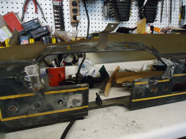
Next is the back of the dash, showing the two lower standoff mounts. They're angled, so they took a lot of massaging to get just right and avoid blocking the stock 914 switch mounting areas.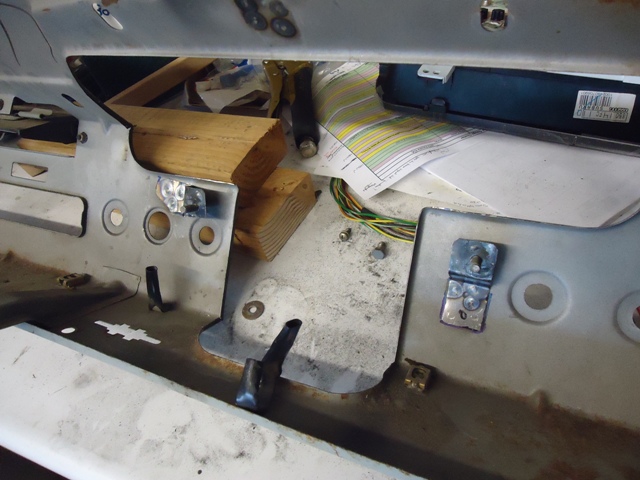
Below shows the back of the dash with the cluster mounted; this picture gives a better perspective of the two lower mounts. 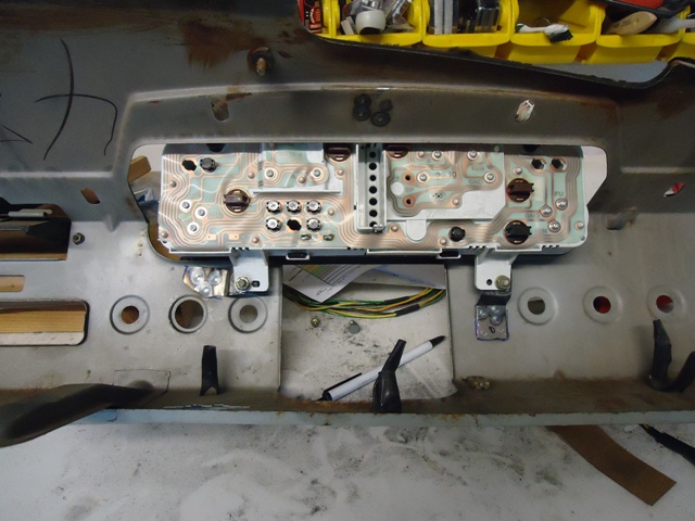
Next is view of the cluster through the steering wheel; I'm also holding up the cluster surround that will help me design the final dash top out of fiberglass. Never mind the state of the cluster face -- I used tape to protect the clear plastic face from scratches during the trial fitting, re-fitting, re-fitting, etc.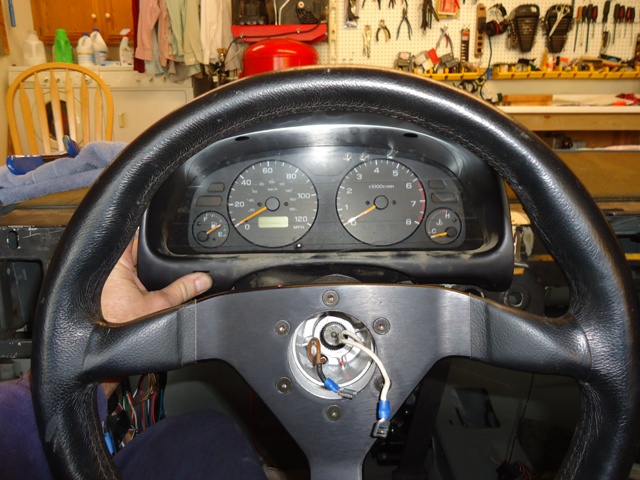
One more pic from an overhead angle. I like it!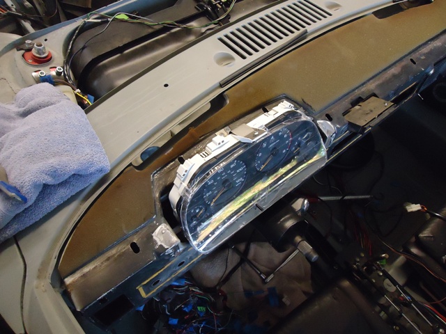
I also was able to change the mounting of my cable shifter, as well as fix the geometry. The former was a simple matter of drilling new holes in the 914 center tunnel and using standoffs to raise my shifter "console" shown in post #115. I didn't take any pictures of the shifter console as mounted, but the shifter is now aligned on a plane with the steering wheel.
I also didn't like the very short throw between 1-2 and 3-4 on my MR2 shifter. The only way to change it is to alter the fulcrum, since the push-pull action of the shifter mechanism on the back of the Suby transaxle is essentially non-adjustable. So I cut off the factory cable attachment point from the MR2 shifter lever, fabricated a new one, and welded it on about 0.5" lower. It is much better now; below are before/after pics of the cable mount.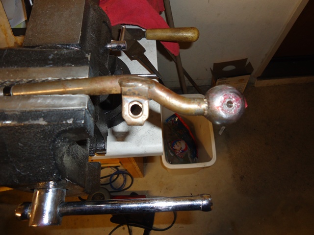
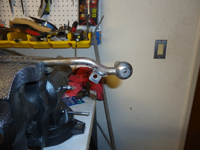
Posted by: charliew Jan 27 2013, 07:50 AM
Great engineering Geoff. The distance from the pivot to the cable mount is probably something me and probably others would like to know. Of course the shifter stalk heigth will also change the throw length. I've never thought about what a "good throw length on a shifter is" but I guess thats up to each builder. I bet in google somewhere there is thread on shifter throw length. The speedometer deal reminds me of a co-worker in the 60's that hooked a drill up to his 63 chevy's speedo and ran it forward for a few days. He might have run it backward, I really don't remember though but with the sender you might come up with something. I wonder how fast you could spin a sender? 200 - 300- 500mph? Or of course check the conversions threads on the suby sites.
Posted by: scotty b Jan 27 2013, 09:00 AM
Really cool about the dash. The shape and size of that one will make it look like a modern 914 dash It's kind of amazing how close in size all of these Subaru parts are, from the drivetrain to the gauges. It's almost like they were meant to be the modern 914 
Posted by: charliew Jan 27 2013, 09:26 AM
I think of suby more like a awd more modern peoples car. Like the early vw you can hop them up but really only so far as the drivetrain is only so good for about 350- 375 hp.
Posted by: kg6dxn Jan 27 2013, 09:35 AM
Great progress!
Posted by: Chris H. Jan 27 2013, 10:37 AM
Awesome gauge setup! I was looking for a 6 cyl manual cluster myself. Just trying to figure out how interchangeable they are electronically. Assume it's like everything else (legos). Great work!
Posted by: ruby914 Jan 27 2013, 11:10 AM
Looking good Geoff.
On the two lower mounts for the cluster, after final assembly, is that set up in a way that you can remove the cluster easy? It looks like you have nuts behind the dash that will be unaccessible later. I am sure you will remove it many more time before it is all over.
Posted by: strawman Jan 27 2013, 02:06 PM
On the two lower mounts for the cluster, after final assembly, is that set up in a way that you can remove the cluster easy? It looks like you have nuts behind the dash that will be unaccessible later. I am sure you will remove it many more time before it is all over.
Yeah, it is a bee-otch to reinstall the nuts when the whole dash cluster is finally bolted in. I did a practice run once to see if it CAN be done; lotsa swearing, but not so bad that I was forced to throw wrenches. The driver's side mount is the worst of the two.
In any case, the future/eventual dash top will need to be removed to pull the cluster or access the lamps as I've constructed it. Not the best option, but I couldn't come up with a good alternative without cutting the front of the dash structure. As I'm typing this, I am thinking that might be a better option, as long as I can remove a dash face cover without removing any switches. Any other ideas?
Posted by: Amenson Jan 27 2013, 02:22 PM
As I'm typing this, I am thinking that might be a better option, as long as I can remove a dash face cover without removing any switches. Any other ideas?
Rivnuts!
Cheers,
Scott
Posted by: strawman Jan 27 2013, 06:33 PM
I actually have a copycat Rivnut tool from Harbor Freight that works reasonably well. However, the cluster tabs are at an angle to the face of the dash. I ended up cutting off the original standoff stud mounts and fabricated new standoff mounts with welded-on nuts. I had to drill two holes in the face of the dash so that I could access the Allen head bolts from the front-side. See pics below.
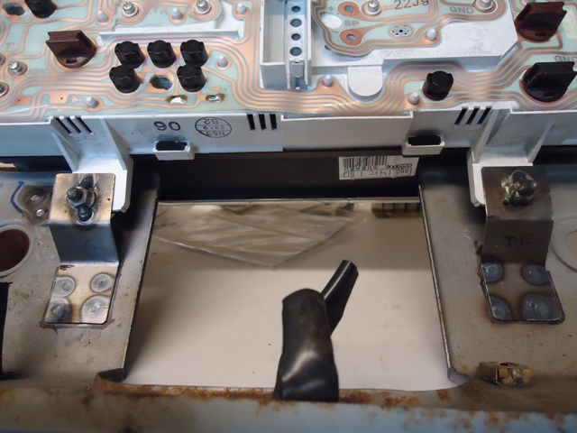
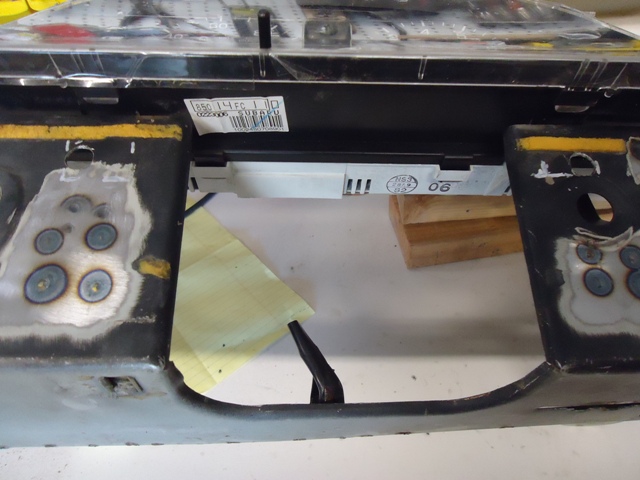
This setup will allow me to remove the cluster to replace bulbs without removing the to-be-built dash top. Much better solution; thanks Ruby914 for making me re-think my original design.
Posted by: strawman Feb 3 2013, 03:32 PM
I don't really like the feel of the 914 seats, so I picked up a pair of fabric seats out of a 1994 Mazda Miata for $50 on Craigslist. Below are the details of the mod; it took me about 15 hours of fabricating time to install these seats.
In order to make it easier to measure and not have to lug the seats in/out of the car, I built a jig based on the hole spacing on the bottom of the Miata seat. It should be noted that the driver-side seat has east-west holes that are closer than the passenger side (hint: don't build the jig exactly for the driver side first and expect it to fit the passenger side!). I used an old bed frame I found with a "for free" sign on the street -- gotta love college towns!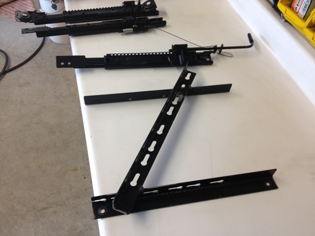
The first picture shows the Miata rails before and after. I am using two 6mm screws to bolt the rear of the modified Miata rail to the factory 914 hinge plates. I had to remove the two heavy-duty rivets to remove the stock Miata rear mount, and weld on new mounts. I also chopped off the forward portion of the Miata rails, and welded pieces of angle iron for the front mounts.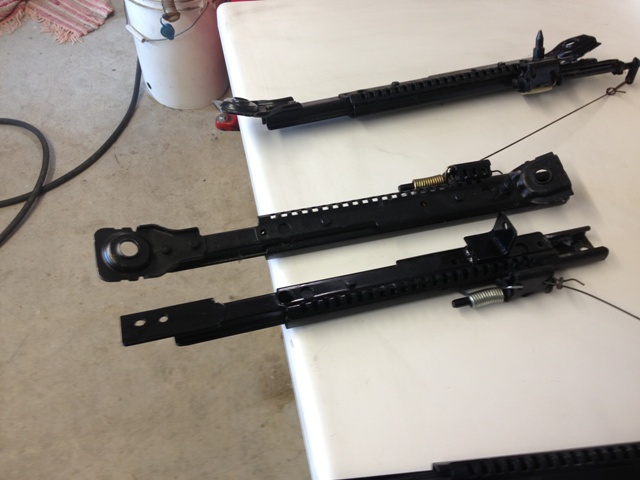
Hear is a close-up of one front mount, and another of the rear mounts.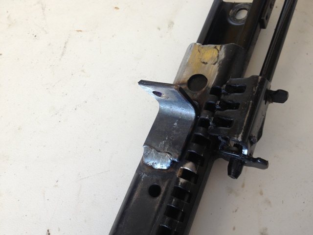
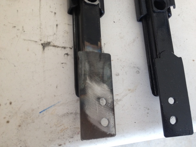
Now comes the part that will make some people cringe: the Miata seat bottom is relatively deep, and the lower pan protrudes below the rail level... which means you have to chop/lower the seat crossmember 0.75". Although the picture below doesn't show it very well, the bright steel piece is what I bent up using a couple of pieces of angle iron pinched in a vise in lieu of using a sheet metal brake. Each 18 gauge piece (driver and passenger) took about an hour, so a brake would've really helped out.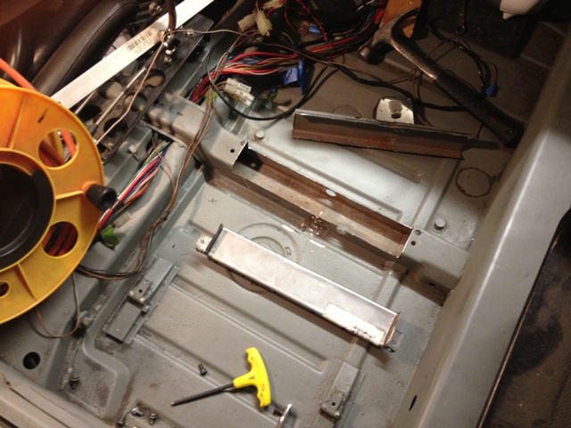
Here is the piece rosette welded in on the passenger side. I actually bought a flange/hole-punch tool from Harbor Freight a while back, and that thing is sweet for making the holes sans burrs. You can see the two holes in the front; those are nut plates that I welded in for the front mounts.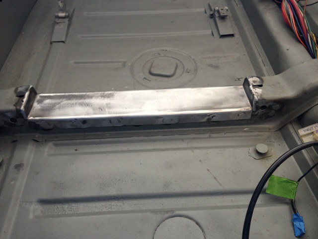
Here is a picture of both sides welded in.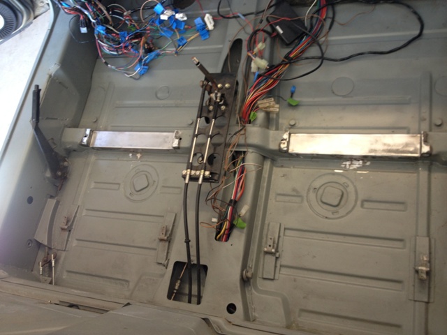
Here is a frontal view of the seats, followed by an angled one.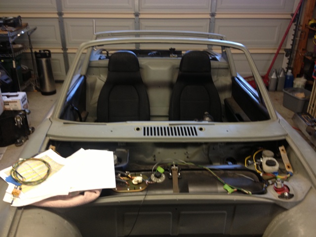
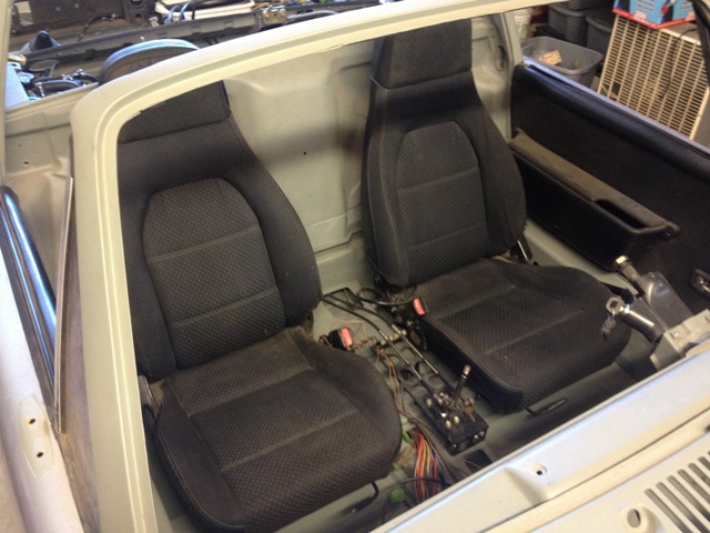
Finally, here is a close-up of the parking brake clearance. While it is a little tighter than the stock 914 setup, I have no problem access it. Cheers, and go 49ers!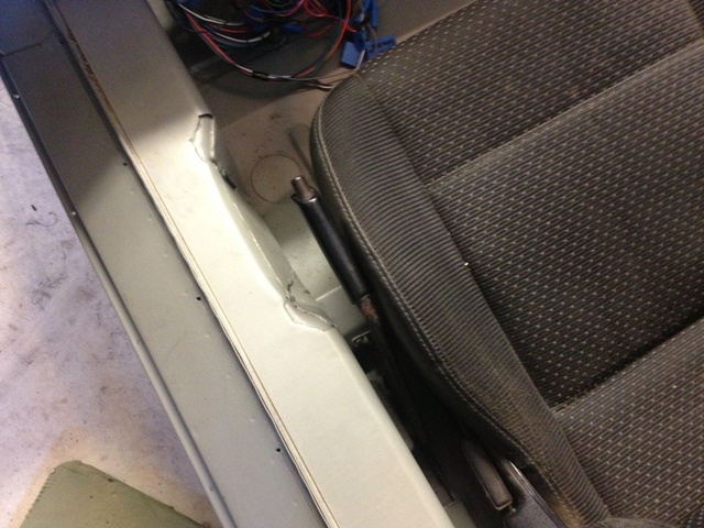
Posted by: scotty b Feb 3 2013, 04:32 PM
Very cool . Have you put the backpad in yet ? It would be really trick to make a new backpad that fit those seats
Posted by: strawman Feb 3 2013, 04:40 PM
Have you put the backpad in yet?
Nope, I will be doing the felt carpet thang...
Posted by: charliew Feb 4 2013, 09:56 AM
I bought some leather seat covers for both my fiero and a 87 mercedes on ebay from china, for a really good price a coupla years ago. The leather is nice and the stitching looks good. You might check it out if you are going to recover those seats. I have thought about using some fiero seats I have that are extra but they may be too wide.
Those look like they fit good. The hot rod guys like the fiero seats because the bottoms are low.
Posted by: Patmagic Mar 14 2013, 12:22 PM
Hello all. Hope I'm in the right place. Thinking of buying a 73 914 with the Subaru svx conversion already done (in a garage) It's a California car so no rust. How do I know if it's been done reasonably correct. Can I assume that the worst thing that could happen is that the engine could be bad and I'll just need to replace it. It's an SVX 6 with the 914 transmission. My goal is to be able to drive anywhere without worrie. Any insight would be appreciated. Thanks
Posted by: KELTY360 Mar 14 2013, 12:45 PM
Hello all. Hope I'm in the right place. Thinking of buying a 73 914 with the Subaru svx conversion already done (in a garage) It's a California car so no rust. How do I know if it's been done reasonably correct. Can I assume that the worst thing that could happen is that the engine could be bad and I'll just need to replace it. It's an SVX 6 with the 914 transmission. My goal is to be able to drive anywhere without worrie. Any insight would be appreciated. Thanks
I suggest you start a new thread. You'll get faster, more compete answers. SVX is an awesome engine!
Posted by: Patmagic Mar 14 2013, 01:29 PM
Hello all. Hope I'm in the right place. Thinking of buying a 73 914 with the Subaru svx conversion already done (in a garage) It's a California car so no rust. How do I know if it's been done reasonably correct. Can I assume that the worst thing that could happen is that the engine could be bad and I'll just need to replace it. It's an SVX 6 with the 914 transmission. My goal is to be able to drive anywhere without worrie. Any insight would be appreciated. Thanks
I suggest you start a new thread. You'll get faster, more compete answers. SVX is an awesome engine!
Will do. New guy mistake. Thank You!
Posted by: strawman Jun 25 2013, 09:27 PM
Damn, too long since I updated... or even worked on my 914, for that matter. I've been busy with other projects, including two Bimmers (an M52 engine / ZF trans swap into a '96 318ti and street/track suspension install, and a rear suspension repair & fortification on a '99 Z3 M Roadster). Now it is time to get back on the 'teener!
I spent a lot of time seam-welding the car, and don't like the idea of cutting some of the front structure out to vent the radiator cooling air. Since I've got a spare front hood, I thought I'd try venting through the hood. As explained earlier, I'm running a Griffin 25272 aluminum radiator and fan/shroud from a Lincoln Mark VII. I bought a spare Lincoln fan/shroud so that I could use a portion of the Lincoln shroud base to build a polystyrene buck without ruining the one I plan to use.
I bought a 4'x8' sheet of 2" polystyrene from Home Despot and went to town -- I used 3M contact cement to glue each layer to the next, and then cut/filed it into shape using a cheese-grater kind of file, a handsaw and 60-grit sandpaper. Hint, don't use polystyrene; use polyurethane instead (so you can melt it with acetone when voiding the buck!). That took about 10 hours to glue, shape, mock-up, shape, mock-up, shape, etc. I then covered the buck with clear packing tape and rubbed on two layers of mold release wax. Below is a pic.
Then I laid the fiberglass, using 2oz mat for the big stuff and 1oz woven cloth for the corners and compound bends, and two-part epoxy. Below are couple of pics of the materials. There are plenty of websites showing how and what to use, so I'll spare the details here.
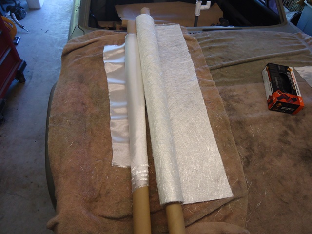
The epoxy is more expensive than traditional polyester resin, but it doesn't smell as horrid and it can be stronger if carefully applied. The roller is key to getting the air bubbles out, and el cheapo brushes ((15 for $10 at HD) work well to wet-out the cloth on a piece of cardboard. Be sure to use gloves or you'll be picking/rubbing resin out of your fingers for days (AMHIK).
My goal was 1/8" thickness, although you can see I've ended up with some thicker spots where overlapping of the cloth/mat occurs. I plan to sand it down and spread a thin layer of Bondo once I complete the proof-of-concept...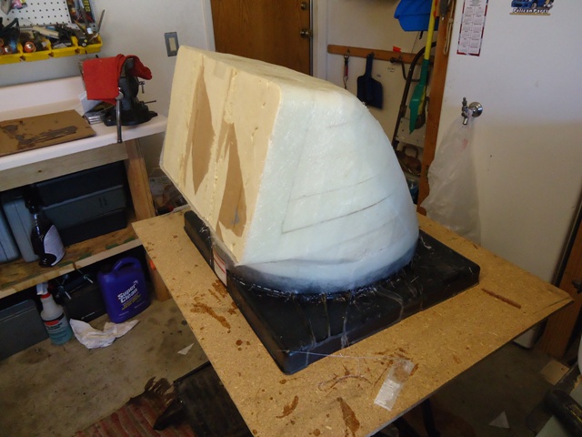
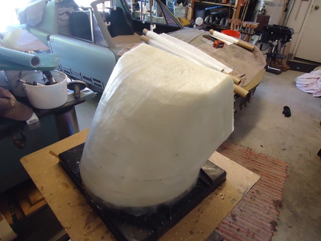
Here is a pic of the shroud released from the buck. As mentioned above, the type of material I used for the buck didn't melt when I applied acetone -- to my surprise. So I used a serrated kitchen knife (don't tell Nancy!) to begin carving it out, then I was able to break out large pieces. Pretty slick on the inside, eh?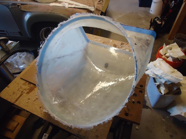
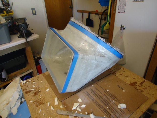
I then trimmed away the edges using a saber saw, and then a sandpaper block to knock down the (VERY!) sharp edges. Here are a few pics of the trimmed fiberglass shroud placed on the Lincoln shroud housing. You can see some of the buck debris in the trash can in the background.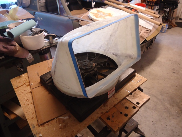
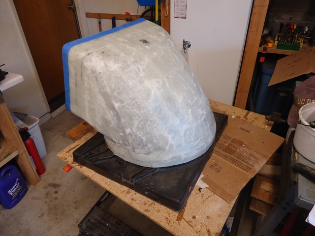
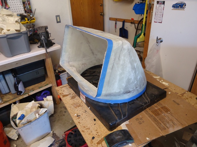
Finally, here are a couple pics of the assembly placed in situ. I plan to carefully mark where the hole in the hood is required, and then incrementally cut away the outlet hole. I planned the hole to maximize the outlet size without cutting into the hood reinforcements, and I nailed it. 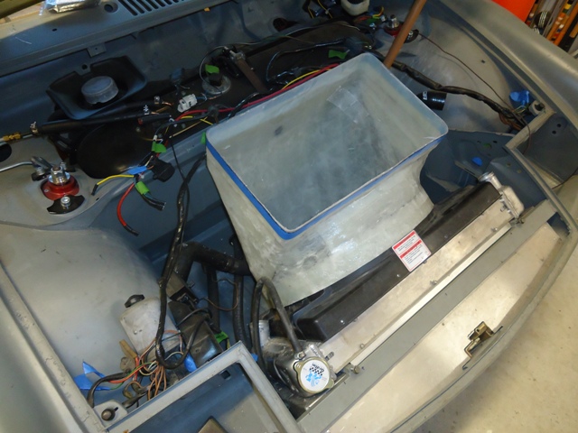
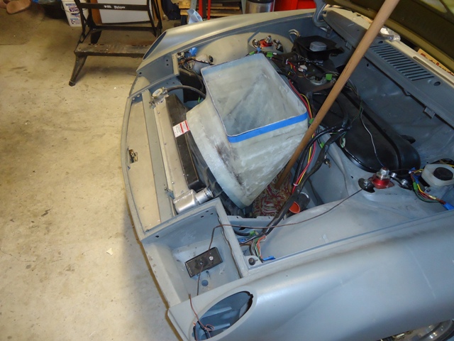
Posted by: ruby914 Jun 25 2013, 10:09 PM
Beautiful
You make it look so easy
Posted by: 76-914 Jun 25 2013, 10:10 PM
sweet
Posted by: wingnut86 Jun 25 2013, 10:14 PM
EXACKERY!!!
Slick plan.
Posted by: effutuo101 Jun 25 2013, 11:27 PM
Nice work! Giving me ideas.
Posted by: kg6dxn Jun 25 2013, 11:38 PM
Cool work!
Posted by: ruby914 Jun 26 2013, 01:33 AM
I bought a 4'x8' sheet of 2" polystyrene from Home Despot and went to town -- I used 3M contact cement to glue each layer to the next, and then cut/filed it into shape using a cheese-grater kind of file, a handsaw and 60-grit sandpaper. Hint, don't use polystyrene; use polyurethane instead (so you can melt it with acetone when voiding the buck!).
It sounds like you went to Home Depot looking for EPS foam (expanded polystyrene) and they gave you polyurethane? Polyurethane is the one that will not melt with acetone or polyester resin. MEK may break it down?
EPS is the stuff with the little white beads stuck together: peanuts, and coffee cups...
It's all the better, melting EPS is a sticky mess. Also when you sand EPS the beads get everywhere and you get a lot of static cling. I like EPS it because you can cut it with a hot wire.
One thing you can do when building your buck is to build it with a removable core plug. Pull the core plug and it is a lot easier removing foam from around the walls.
Anyway, it looks great! Are you going to paint it the same color as the car
? Posted by: Chris H. Jun 26 2013, 08:01 AM
Nice work! Giving me ideas.
 Awesome man. Definitely stoking the fire on my plan as well. I want to vent through the floor and use louvered panels to keep water and debris to a minimum...that setup would be great to redirect the air right out the bottom.
Posted by: Tilly74 Jun 26 2013, 08:52 AM
Posted by: Zaney Jun 26 2013, 11:12 AM
Looks awesome, Geoff!
Seems we both have been playing with fiberglass! I am making a new gauge plate for my SpeedHut gauges.
Your skill and attention to detail is one to be emulated
Nate
Posted by: strawman Jun 26 2013, 06:13 PM
Are you going to paint it the same color as the car
?Yup, that is the ultimate plan. But I wanna run this first to see if it meets my expectations for cooling; then I'll make it all purty.
Thanks for your advice on the type of foam to use. I'll need to mock up a lip on the leading edge of the hood outlet to create a low-pressure spot after I cut out the hole, so I'll look for the good stuff. I've got some designs rolling around in my head but I haven't settled on one yet. Most of the websites say to use the high-density blue or green urethane for the buck -- but I could only find small bricks that cost too much at craft stores like Michael's or Joann's (which are places that always seems to reduce my testosterone levels...).
Posted by: strawman Jul 1 2013, 07:54 PM
After a terrible weekend at the 24 Hours of Lemons Button Turrible race (our Opel GT only did five laps before destroying the head gasket in 106 degree weather!), I came home and worked out my frustration on the cooling system of my Suby-teener. If I woulda been smart I woulda suffered the extra heat of long-sleeve pants and shirt to keep the fiberglass dust off my sweaty exposed skin. The result is my arms and legs are uber-itchy today!!!
The first picture is of the measuring system I devised to locate the hole I needed to cut in the hood, as well as the height of the shroud under the hood. I placed painter's tape along the top of the inner fenders and along the front/rear edges of the hood area. I then used a straight edge along the sides of the shroud to make Sharpie marks on the blue tape. I then used a 12-foot length of copper ground-wire bent to surround the shroud outlet and to mimic the curvature of the hood. In the picture below, you can see the copper piece and the Sharpie marks on the blue tape. 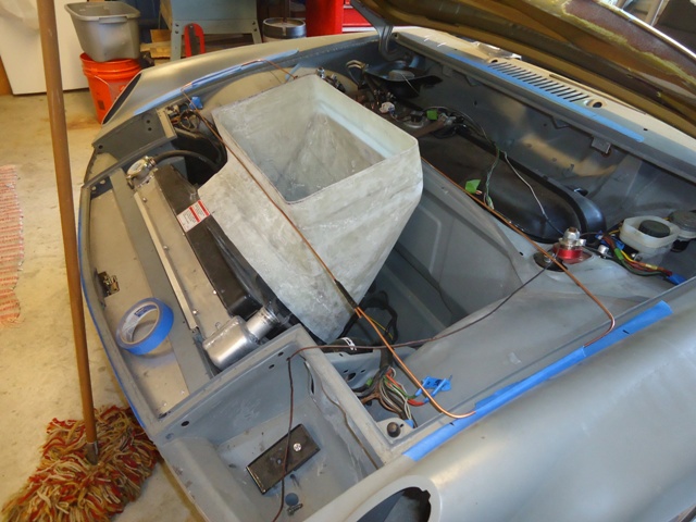
I used the copper wire to also make approximate height cut-marks on the shroud. I then removed the shroud from the radiator to make the first cut of the fiberglass shroud -- I actually made the cut using a saber saw about 1/2" above the Sharpie line to give me a chance to incrementally cut down to the correct height.
Below is a picture of the blue tape I lined up with the Sharpie marks along the four edges of the hood. I then drilled holes at the corner of each cut to avoid future cracks that tend to occur at right-angle or straight cuts. I'm not sure if you can see the areas marked "down" -- those ten areas will be for the tabs I'll bend down and use to mount the mesh screen. The front leading edge has two longer areas that will be further sectioned and used to provide a strong support for a forward lip to create a low-pressure zone that should aid in sucking the hot air out. You'll note that there is a curvature to the hood, so you cannot merely bend the long tabs along a straight line or you'll tweak the hood.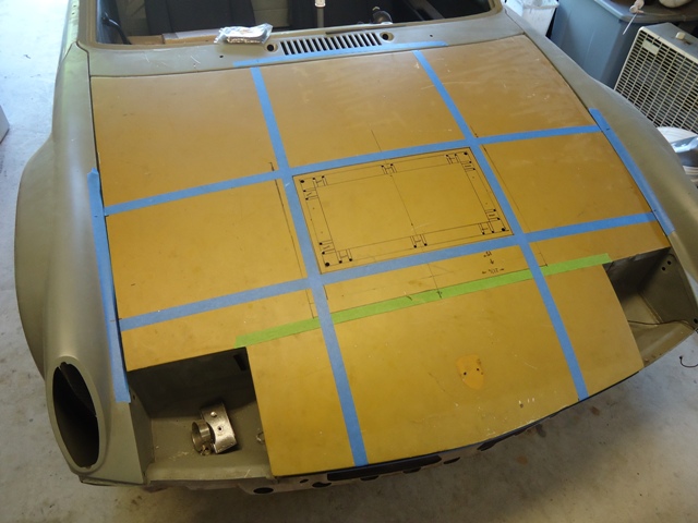
Below you can see the cut-outs; one pic from a rear corner and the other from the front. I used a combination of a 3" cutting wheel (1/16" thick) in a die grinder and a saber saw to make the cuts. I went as slowly as possible to avoid warping the metal too much.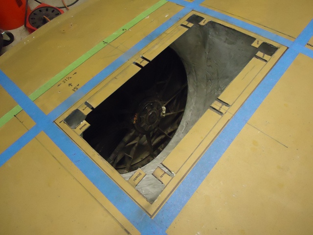
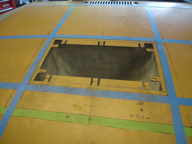
The three pictures below show the rear two pieces cut out, and the area cleaned up a bit. I plan to bend 1/4" steel rod and tack-and-then-fiberglass on the bottom-side of the hood cutout for strength.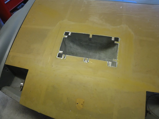
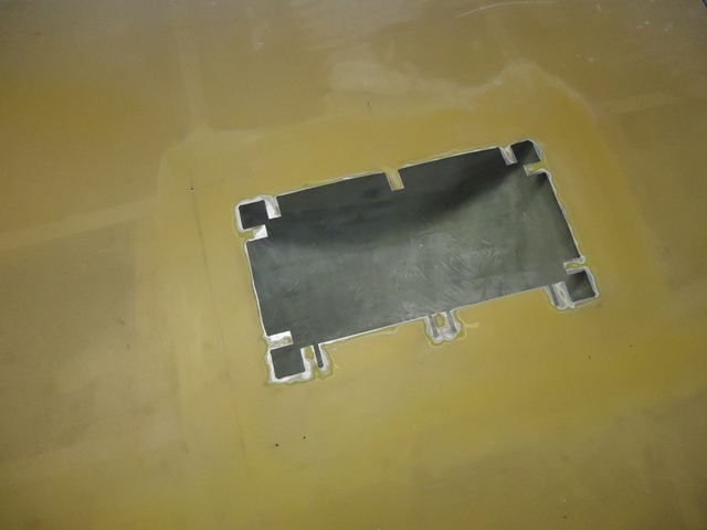
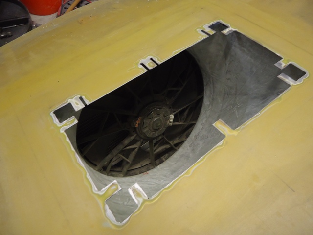
Finally, the two pics below show the shroud trimmed to the correct height -- 3/8" below the bottom of the hood. Honestly, it took about 20 times of measuring, marking & cutting before I "snuck down" to the right height. The hood outlet "box" hole is 1/2" smaller on each side than the inner box size of the shroud. That was done so that the rubber gasket I'll install on the fiberglass shroud top will ensure a good seal that won't rub too much on the bottom of hood box structure. I used 5mm stainless steel hex-head bolts, ss fender washers and ss nylock nuts to mount the fiberglass shroud to the Lincoln plastic shroud. 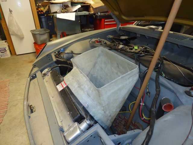
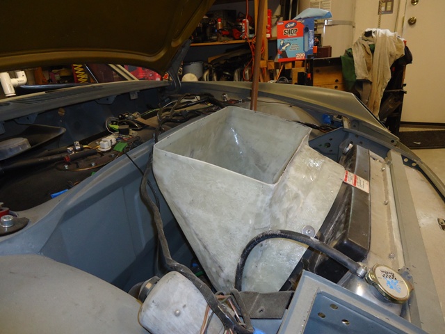
I still need to cut & grommet a hole in the fiberglass shroud to snake through the fan wiring, and to add a grommeted drain hose for any water that might get through the hood hole. Finally, I need to mock up and construct the leading lip and possibly declining side edges (for good looks) for the hood hole. I hope to get to these projects this next weekend.
Posted by: 914forme Sep 30 2013, 01:47 PM
Looks great updates
Posted by: CptTripps Oct 17 2013, 07:13 AM
Just a thought...
Would you have been able to point that DOWN instead of having to cut the hood? It seems like you'd get almost as much airflow out of the bottom of the trunk floor as you would from up high.
I only ask because I am thinking of building something similar and want to explore all the options before I go too far.
Posted by: badmiata Oct 17 2013, 02:23 PM
That's a good question that I haven't seen anyone answer! It would be nice to preserve the outside look without having to cut into the wheel wells. PLUS what do you do if it rains? will that hold water, were does it drain?
Posted by: skeates Oct 17 2013, 02:43 PM
Your work looks top notch! I had planned on going a very similar route for my radiator venting - your posts here have been very informative
Would you have been able to point that DOWN instead of having to cut the hood? It seems like you'd get almost as much airflow out of the bottom of the trunk floor as you would from up high.
Seems to me that if one were to vent all of the radiator air under the car it would create a high pressure area right where you don't want it - making the front end scary light at higher speeds. Venting through the hood should actually result in a bit of down force at higher speeds. I think others have been successful venting their radiator through the floor, just doesn't seem to be an ideal solution.
Posted by: mgp4591 Oct 17 2013, 04:56 PM
Your work looks top notch! I had planned on going a very similar route for my radiator venting - your posts here have been very informative
Would you have been able to point that DOWN instead of having to cut the hood? It seems like you'd get almost as much airflow out of the bottom of the trunk floor as you would from up high.
Seems to me that if one were to vent all of the radiator air under the car it would create a high pressure area right where you don't want it - making the front end scary light at higher speeds. Venting through the hood should actually result in a bit of down force at higher speeds. I think others have been successful venting their radiator through the floor, just doesn't seem to be an ideal solution.
Maybe split it and vent thru the front of the wheelwells?
Posted by: RonW Oct 20 2013, 09:11 PM
awesome work. stole a few ideas for my project. keep it going!
Posted by: ruby914 Mar 8 2014, 02:53 PM
Looks great updates Looks great, need an update Posted by: CptTripps May 29 2014, 09:26 AM
Bi-Weekly ![]() for updates!
for updates!
Posted by: Andyrew May 29 2014, 01:21 PM
Are you going to make a lip in front of the hood cutout to create a low pressure area to draw the air out? If you dont I forsee that you'll have a bit of air turbulance at speed.
Posted by: Mike Bellis May 29 2014, 02:43 PM
Just a thought...
Would you have been able to point that DOWN instead of having to cut the hood? It seems like you'd get almost as much airflow out of the bottom of the trunk floor as you would from up high.
I only ask because I am thinking of building something similar and want to explore all the options before I go too far.
Then you add too much air under the car and the car lifts off the ground. This is bad!
In stop and go traffic it also will blow hot air down, out and around into the cabin... Ask me how I know...
Posted by: 76-914 May 30 2014, 11:40 PM
Just a thought...
Would you have been able to point that DOWN instead of having to cut the hood? It seems like you'd get almost as much airflow out of the bottom of the trunk floor as you would from up high.
I only ask because I am thinking of building something similar and want to explore all the options before I go too far.
Then you add too much air under the car and the car lifts off the ground. This is bad!
In stop and go traffic it also will blow hot air down, out and around into the cabin... Ask me how I know...
I hadn't considered that before. Good points, Mike!
Posted by: Chris H. May 31 2014, 11:36 AM
Yeah I was really close to venting through the floor 'til Mike told me that.
He also said some thing about..."if you end up on a dirt or gravel road you'd better hope the fans don't come on or you'll be sorry...ask me how I know.... "
That closed the book on that one. Fine for the track or in situations where you'll pretty much always be moving. Not fine if you'll drive the car like a normal car.
Posted by: BIGKAT_83 May 31 2014, 08:39 PM
I know of a couple of conversion cars venting out the bottom and it seems to work fine. If I had a car that had been cut in the floor for a AC unit I'd sure give it a try. I just can't bring myself to cut the floor after I welded in patch panels for the AC cut outs.
Bob
Posted by: Mike Bellis May 31 2014, 11:17 PM
Yeah I was really close to venting through the floor 'til Mike told me that.
He also said some thing about..."if you end up on a dirt or gravel road you'd better hope the fans don't come on or you'll be sorry...ask me how I know....
"That closed the book on that one. Fine for the track or in situations where you'll pretty much always be moving. Not fine if you'll drive the car like a normal car.

True story... I was at the Goodguys car show creeping my way through the dirt parking lot when all of a sudden... WHOOSH! Fans kicked on and I got a mouth full of dust...
Posted by: CptTripps Jun 2 2014, 06:08 AM
Finally, here is a picture of the engine bay with the air-water intercooler and all turbo piping installed. I welded up stand-off mounts using 3/16" rod, which I'll powdercoat after I finish up mounts for the fuel lines, wiring, etc. I still need to finish up the MAF, air cleaner and related piping/mounts.
I REALLY wish I could have flipped my intake like this. The way my radiator is set up, makes it impossible. So now I'm stuck trying to cram a ton if intake/outlet tubing in a very small space. It's got me wondering if air/water is really worth the effort at the end of the day.
Posted by: strawman Jun 14 2014, 02:58 PM
Wow, has it really been almost a year since I last updated? Been busy with a couple of other projects (M52 in my BMW 318ti, rear suspension repair on my BMW Z3 M Roadster, etc.), but I've been working in a little 914 love here-n-there...
The pics below are the second iteration of trying to use a 1998 Subaru Forester dash pod. The first was trying to modify the stock 'teener upper dash cover to accept the Suby pod. The Suby pod is too tall to fit, so I cut out the top of the dash cover (don't worry -- it was far from pristine!) and welded in a new upper hoop. After finagling with the 'teener dash pad for too long, I finally gave up because the proportions were just wrong. That was 20 hours down the drain.
So I mocked up what I wanted to achieve using polystyrene for a fiberglass buck. I tried to model the pod cover after the fender flares, while also using the Subaru binnacle (the stock piece that sits up against dash pod) to make it look as smooth/tight as possible to the Suby dash pod. What is shown below is actually the second take on it, since the first pod cover could not be independently removed without having to remove the whole dash... gotta be able to replace dash lights without wanting to crush the car, ya know. That was another 15 hours down the drain.
Because I'm not using the stock 'teener upper dash cover, I couldn't use the lower dash cover either. So I welded up the ashtray, seat belt warning light hole, the upper/lower dash holes, and the stiffening "crimps" along the top and bottom. Hard to explain the latter, but if you look at the pics below you'll see the bent-diamond shaped pieces I welded in. I also welded up the holes where the various switches (headlights, fog lights, etc.) were mounted and will drill/mount those once everything is set up to make sure they fit where I want 'em. I'll have to modify the dash vents to fit the stock metal holes, since in the stock configuration they mount in the lower dash cover.
First up are a couple pics of the rough pod cover. You can see that I welded nuts onto backing plates and fiberglassed these four units in.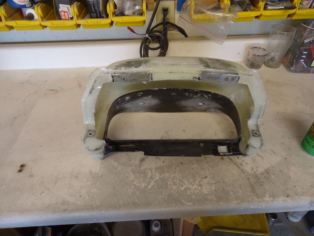
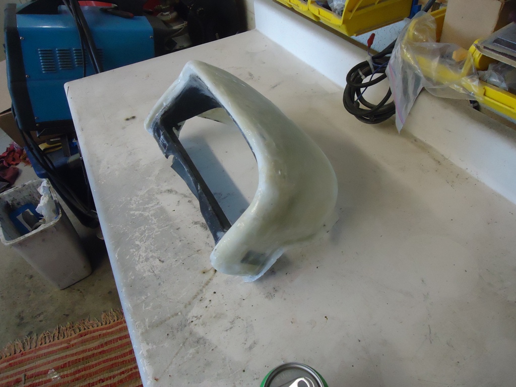
You can see the black plastic binnacle 'glassed-in as mentioned above. I wanted to be sure that the curved and convex Suby dash pad wouldn't have any gaps that would make me squeeze the steering wheel while driving because I hokied it up...
Next up are some pics of the mods I made to the stock 'teener metal dash. What is shown below is the welding work and then Metal Ready prior to getting epoxy primered. The pics don't show final metal work (shrinking, pinholes welding, etc.) necessary before skimming with bondo and smoothing. You also wont see in the pics below that I smoothed the outside corners/edges that could only be seen when the doors are open (this is normally covered by the stock 'teener upper and lower dash covers).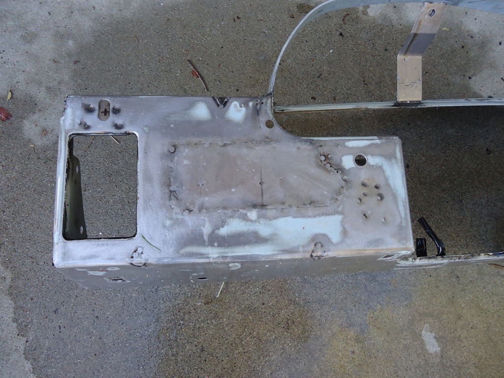
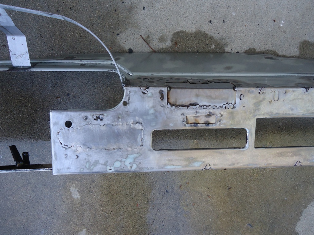
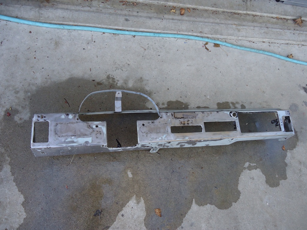
The two holes that are above and to either side of the steering column are used for the two Suby pod lower mounts. I had to weld in two mounts that you can see in the pic below of the backside. The Suby pod has a single mount on the top; I welded in a nut for this mount, which you can also see attached to the upper hoop.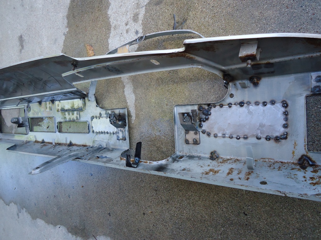
Next up are some pics of everything mocked up. My next step is to decide if I want to have the pod and the metal dash covered (i.e., Alcantara), or if should finish-smooth eveything and paint it matte black or slightly textured black. Opinions?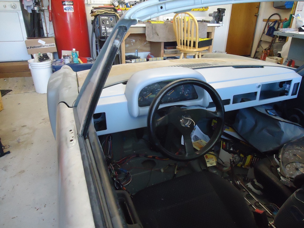
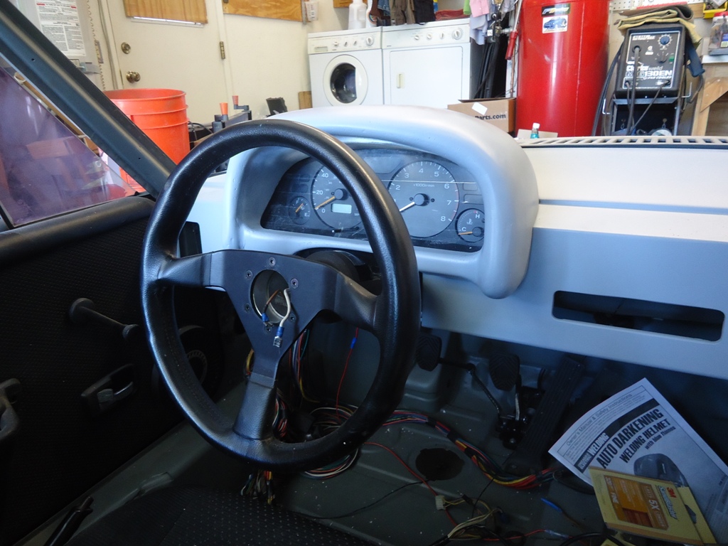
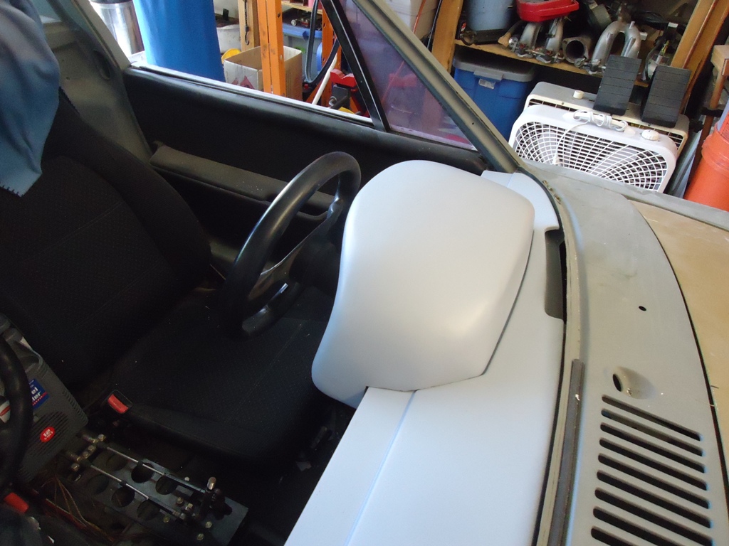
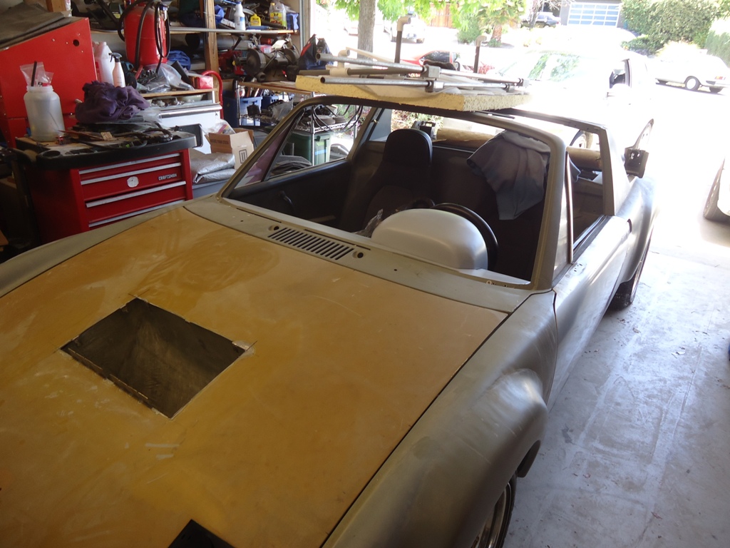
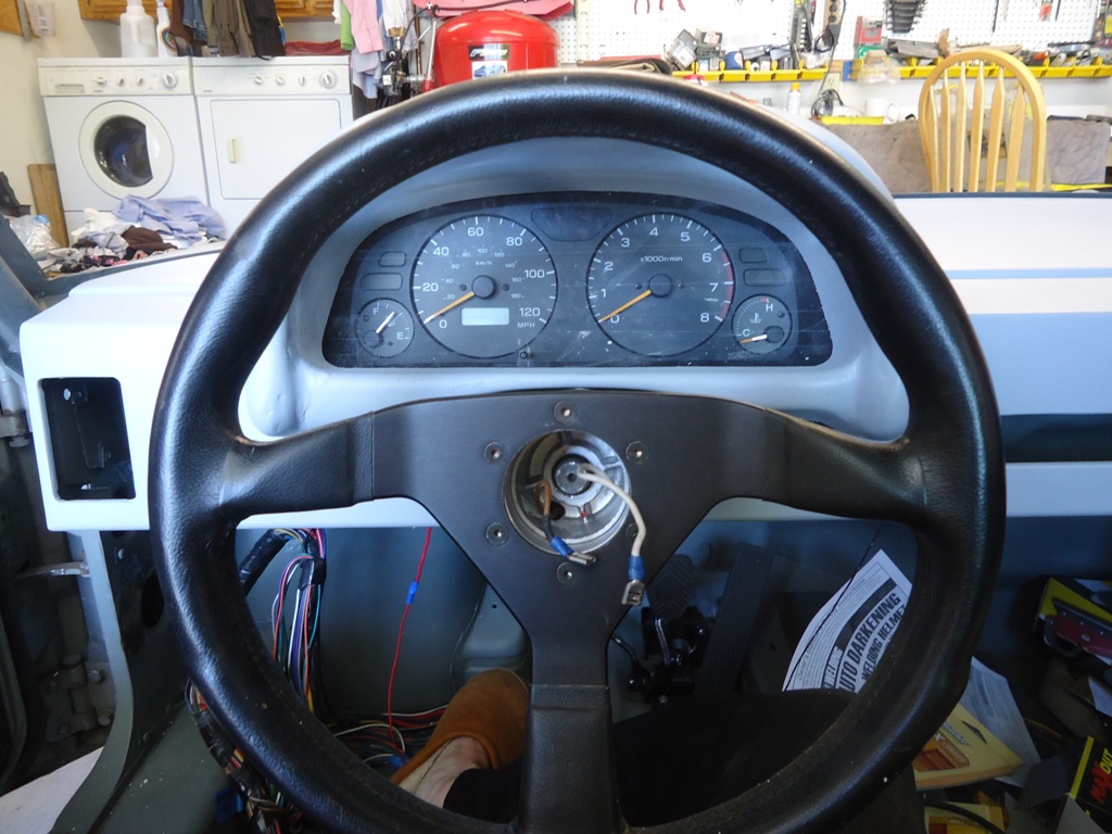
Posted by: 76-914 Jun 14 2014, 03:11 PM
Looks great. I laughed as I read of wasted hours due to experimentation.
Posted by: Chris H. Jun 14 2014, 08:46 PM
Yeah that looks GREAT! You can't go wrong with either...painting or covering it will look nice.
Hours of experimentation...put me down for DAYS!
Posted by: strawman Jun 14 2014, 10:37 PM
I laughed as I read of wasted hours due to experimentation.
I keep a box of receipts for all of my car projects (that I keep hidden from my otherwise understanding wife), but I don't dare track my time. I figure I've got at least 60 hours in this dash project.
Posted by: 76-914 Jun 15 2014, 07:41 AM
I feel your pain . I think I dropped about 20 hr's on those gauges before someone flipped the "dumb ass light" on me. 
Posted by: CptTripps Jun 16 2014, 03:46 PM
That's impressive as hell. Well done sir!
Posted by: charliew Jul 28 2014, 02:00 PM
I haven't seen the product in person but alsacorp.com has announced a velvet wrap for covering exterior panels. The email info I got showed some interior areas done and the photo's looked good. I was thinking I could cover a mercedes dash cover with it and maybe get a decent match to the camel colored leather seats I have for it. i tried to get a link to post here but didn't get it to work. Just google alsacorp.com and search velvet car wrap maybe.
Posted by: Chris914n6 Jul 28 2014, 07:07 PM
Looks good. I've got a similar dash project for my Nissan cluster.
At my local upholstery place the alcantara was surprisingly pricey but I discovered a black vinyl called Keystone Grabber for the under the windshield piece. It's textured and optically near invisible on reflections.
They also had a textured Carbon Fiber vinyl that looked really good. Independant Endura brand.
Both were around $10/yd.
If you don't want vinyl then there is trunk carpet (speaker box stuff) and dash mat carpet that stretches well.
Posted by: strawman Sep 15 2015, 10:44 AM
Holy crap, has it really been more than a year since I last updated? Time flies and other projects get in the way. Most recently: a hopped-up TDI swapped into a Eurovan Weekender that you can see in the background below.
I've pulled the doors and stripped them to bare metal, as well as completed more dash changes (see the holes for Vintage Air dash vents in the second picture below) and mounted the headlight, flasher and fog light switches. I also welded-in verticals into the now-stripped hood to create a low-pressure area where hot air vents up from the radiator and air-to-water intercooler's heat exchanger. I worked out a coolant-based heater & defrost system that seems to capably blow hot air to the right places, and this forced me work out the final engine cooling system. I really like the airbox rebuild kit that 914 Rubber sells -- major league thumbs up. I also want to thank Elliot for providing me the four clips for the airbox housing that I lost; I owe him a cold one.
Here are a couple of pictures of the car in its bare-bones condition.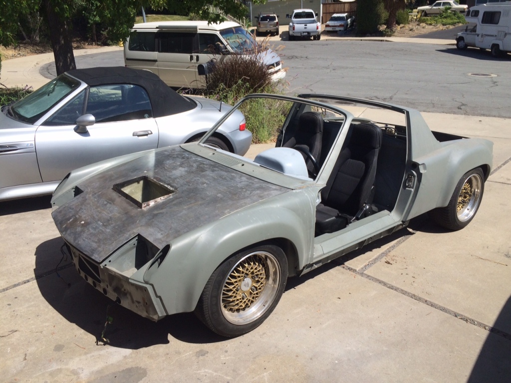
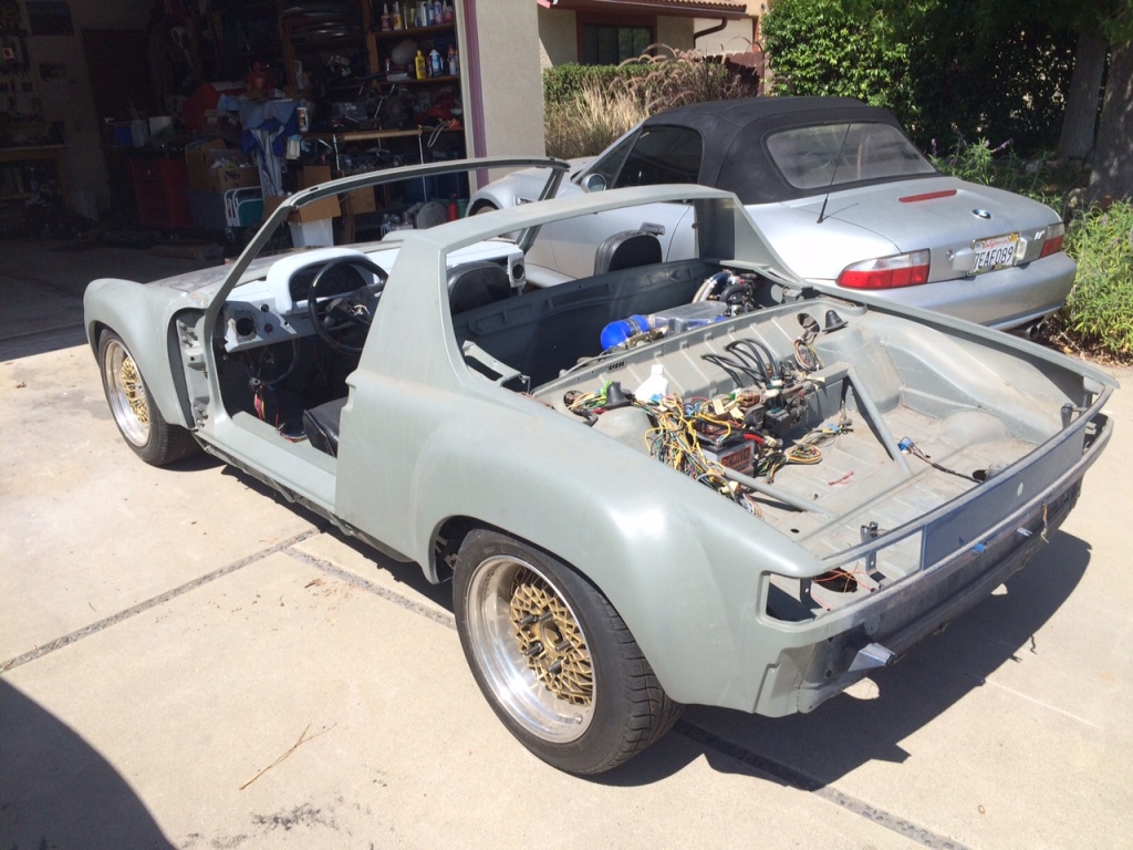
I actually drove the car on my street several times over the weekend, and that has inspired me to focus on this project instead of taking on another (yeah, right! ). It is scary fast when the turbo kicks in, and loud, too. I need to rethink my muffler system or my neighbors are going to shoot me.
I also installed the front hood opening cable & sheath from 914 Rubber -- high quality stuff. Next up is partially reassembling the car and registering it so that I can shake it down before final bodywork and paint.
Posted by: strawman Oct 9 2015, 10:37 PM
Just paid the $650 in back fees to register my project; hasn't been registered in CA since 1989. Now I can drive it legally on the street to work out the bugs. Working out electrical gremlins and will update as progress is made. Stay tuned!
Posted by: JRust Oct 10 2015, 12:06 PM
Congrats bud. Thats a huge step! Can't wait to see that bad boy on the road. After seeing it in person. really want to see you behind the wheel enjoying it
Posted by: 76-914 Oct 10 2015, 06:06 PM
Great work, Dean. What color will you paint this one. I can't wait to see you outdo yourself.
Posted by: arkitect Oct 11 2015, 08:58 AM
You've done some great progress with your teener conversion, can't wait to see it finished. I like the stance and wheels. Great that you got it updated with dmv. That's always a big step. Do you have a color in mind?
Dave
Posted by: strawman Feb 8 2016, 08:09 PM
I finally pulled the trigger and started construction of my new work space. I'm enclosing the side yard, building a concrete pad, and installing a 4-post lift. I'm getting too old to work on my back anymore. I've got the best and most-understanding wife alive...
Below is a pic on the contractor's equipment after Day 1. He plans to pour the concrete stemwall and pad on Thursday. 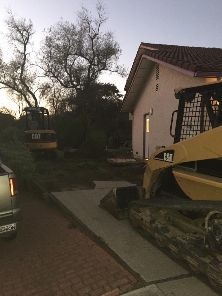
I plan to order an extra-tall 8k 4-post lift later this week from Greg Smith Equipment Sales. More pictures to come as this project moves forward!
Posted by: wingnut86 Feb 8 2016, 08:36 PM
:-))
Posted by: 76-914 Feb 8 2016, 08:37 PM
I'm happy for ya. I always worked around having one. After I got a lift I wondered why I had waited.
Posted by: strawman Mar 29 2016, 06:00 PM
Lift is finally installed. Just need to get electrical hooked up and start wrenching. 
Unfortunately, I'm laying in a hospital bed right now recovering from surgery to repair a screwed up disc in my neck. No driving or even riding in a car for 30 days. So WCR is out for me this year. Anyone need a hotel room?
Posted by: JRust Mar 29 2016, 08:41 PM
No WCR
Sorry to hear you are in the hospital bud. I hope the recovery goes quick for you
Posted by: Andyrew Mar 29 2016, 08:51 PM
Sorry to hear about the injury!!
WCR is in May so there is still time to recover and come...
Nice lift BTW
Posted by: strawman Apr 16 2016, 07:21 PM
Still recovering from my neck surgery, but the electrician finally wired in my lift. Here a couple of pictures of my daughter's '98 BMW 328i on the lift. 
As soon as my doctor clears me, I'll finish the engine swap I did on her car right before my surgery (took the engine out of my M52-swapped '96 BMW 318ti to make room for an S52 engine!), get my 318ti going with its new heart, and then get back onto my 914; you can barely see it in my garage buried under a bunch of
No way I can make WCR this year due to work issues that arose, so PM me if you want my hotel room; otherwise I'll cancel it in the next week to get a refund.
Posted by: strawman Feb 3 2017, 01:54 AM
So the S52 swap is complete in my 318ti (it rips!) and the car is at the painters for a re-squirt in the factory Calypsorot color. I also sold my '99 Z3M yesterday and my wife is letting me use the proceeds to make significant progress on my 914.
I just submitted a huge order inquiry to 914Rubber, and I'm busy ordering other stuff for the project including:
* SubaruGears sight-glass for the transaxle fluid level
* SmallCar cast aluminum shortened oil sump & pickup
* VDO gauges (oil pressure, coolant temp, oil temp and pyrometer)
* Dunlop Direzza Star Spec tires (225/45-16 rear and 205/50-16 front)
* PTP turbo blanket to keep engine compartment temps reasonable
I need to finish up the metalwork on the doors and install an old windshield so that I can drive the car and work out any bugs. Other cosmetic issues include metalworking the air-thru-the-hood hole. I also need to replace the IAC valve to smooth out the idle while warming up; I'll do that while I'm futzing with the gauge senders installation.
I also want to totally rework the shifter mechanism, especially after seeing firsthand Jamie's failed shifter cable at the WCR a couple years ago (my 5/16" cables definitely won't last!). I'm excited to get back onto this project!
Posted by: strawman Feb 5 2017, 05:35 PM
For the first time, I put my teener up on the lift. I was worried it is so low I'd have to drive up on some boards so the arms could swing under it, but there's plenty of clearance. 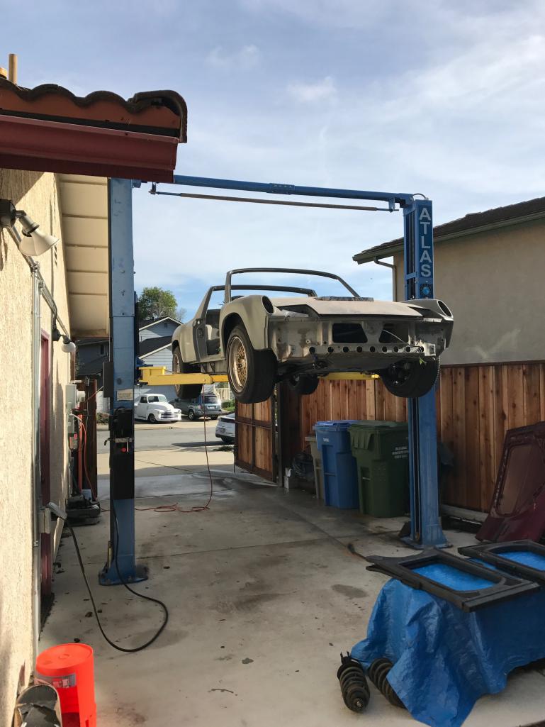
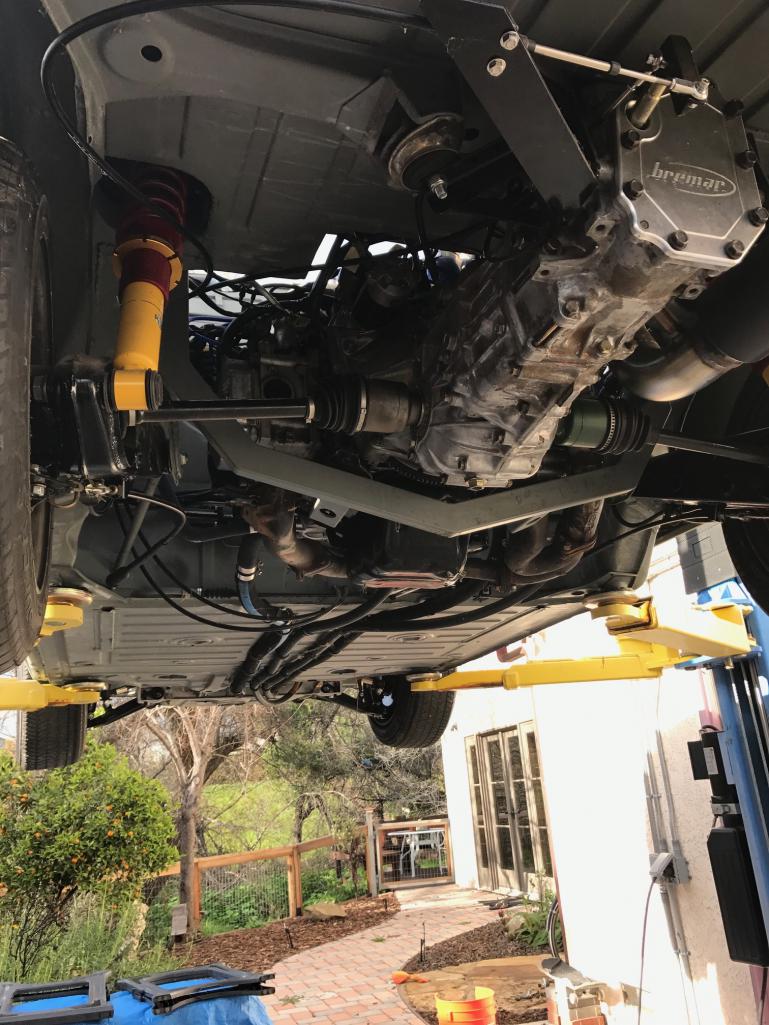
I mentioned in an earlier post that my shifter cables are 5/16" -- but I was way off... they are actually 3/16". You can see how puny they are in the pic above. I'll order some beefier ones in the coming days.
The Suby engine had been idling terribly until fully warmed-up, so I bypassed the Idle Air Control valve this morning. But then it wouldn't rev at all and kept dying. I checked fuses, made sure I didn't mistakenly disconnect any sensors, hooked up jumpers from my Eurovan (because the battery only showed 12.1 volts), and I generally pulled my hair out for an hour. Then I remembered to check the fuel... duh. A quick trip to the local Chevron and she fired right up and idled beautifully. Since I'm not running A/C, I think I'll just permanently bypass the IAC valve.
New tires from TireRack will be delivered tomorrow to my favorite local installer, so I just loaded the wheels in my Eurovan. The VDO gauges/senders, as well as a fuel sender ohm-converter, should be delivered later this week from Jeg's. The cast-aluminum shortened oil pan from SmallCar should also be here this week, so I'll begin installing all of this stuff (and a 3-quart Accusump system) next weekend.
Posted by: JRust Feb 5 2017, 06:14 PM
Nice bud! Looks like you are close to driving that bad boy daily
Posted by: charliew Feb 8 2017, 06:46 PM
looking good. this page is one year old today boy time flies. somehow I missed or forgot the subaru gears sight glass mod. will that also allow for the extra oil level for the additional oil to lube the rear bearing?
Posted by: strawman Feb 11 2017, 09:38 PM
The parts are arriving day by day. My Braille B159 battery is gonzo, so I ordered another on Tuesday. It is not so completely gone that I cannot jump the car, but it is a (first-world) PITA to jockey cars back and forth... the replacement should be here next week.
I had the Dunlop Direzza Star Spec II tires mounted on my E52 BBS Motorsports wheels (16x9 in back and 16x7 in front). I've run a couple sets of these same tires on my DD, and they're a good compromise between grip, noise and tread life.
I spent today on a couple of important projects. First up was installing the Small Car cast aluminum oil sump. It is a very nice piece, comes with all hardware, and I'm really pleased with the clearance -- although it ain't cheap ($360 delivered). The only required mod is having to space the oil dipstick tube upper mount upward about 1/4". Here are some pics of before and after.
Here is the stock Suby oil pan; it hangs about 1.5" below the lowest part of the exhaust header.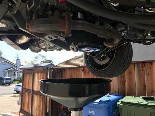
This is the stock oil pickup.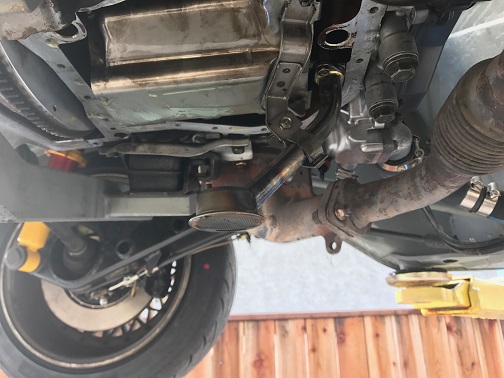
This pics shows the two pans side by side, along with the two oil pickups. 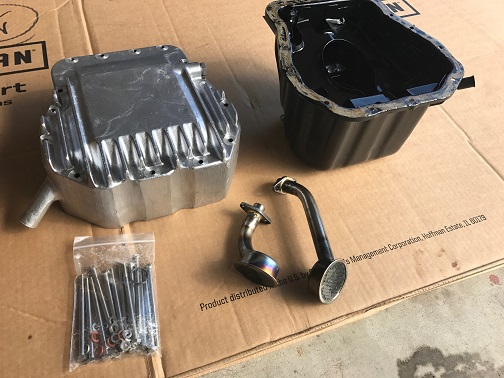
You can see that the oil pan now hangs no lower than the exhaust header crossover. My engine mount now hangs about 3/4" lower than the new oil sump.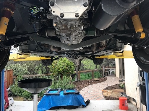
I also installed the Subarugears sight glass. It allows you to raise the gear oil level to appropriately cool all bearings and gears, without overfilling the box. It is a no-brainer, but filling the trans is a messy endeavor even with a lift. I just got out of the shower to clean that nasty-smelling stuff out of my hair.
Here is a pic of the freezeplug pulled out, the hole cleaned, and the sight glass prior to getting Red Locktite smeared on the contact edges.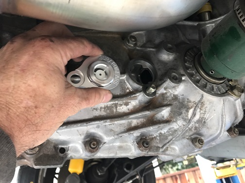
Next up is the backside of the sight glass.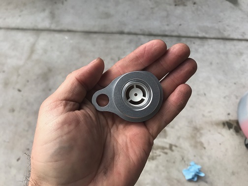
And here is a pic of the sight glass installed. When filled correctly (not yet in this photo), the gear oil level will be on the upper half of the sight glass.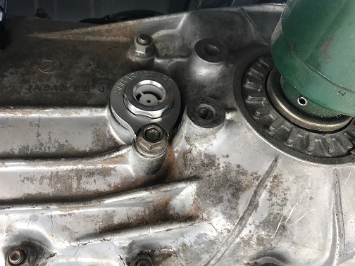
Finally, I installed the PTP turbo blanket. No instructions are provided, but it is pretty intuitive. I also bought wrap for the downpipe, but I ran out of gas (pun intended, based on an earlier post...)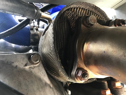
Posted by: strawman Feb 11 2017, 10:03 PM
I also spent some time today figuring out the routing of the oil line and necessary fittings for a 3 quart Accusump system. I'm going to mount it low on the engine-side of the firewall. I've ordered the parts through Jeg's, including an Electronic Pressure Control valve. I will tap into a galley plug hole on the front of the engine. As I'm typing this I'm realizing that I should also protect the oil line in case the alternator belt fails...
Posted by: strawman Feb 18 2017, 07:45 PM
I spent today installing my 3-quart Accusump system. I opted for an electronic pressure control valve instead of the simpler but cheaper manual valve. I'm also using 10AN fittings and a lightweight braided hose from JEGS. Here is a pic of the unit ready to be installed.
I originally wanted to put it down low on the passenger side to help with corner-balancing, but that would mean having to redo fuel, cooling, hydraulic clutch and brake lines. Just about anywhere else would require spacing it because the firewall has so many odd angles. I ended up bolting one side directly to the firewall right behind the driver seat, and spun up some Delrin spacers for the other side. The instructions recommend tilting it up slightly up at the valve end, which further complicated the mounts. But it came out nicely, with the valve essentially lined up with the oil galley plug and about a six-inch oil line; the 90-degree fitting is a swivel unit, so it should help handle engine movement. Below are a couple of pictures.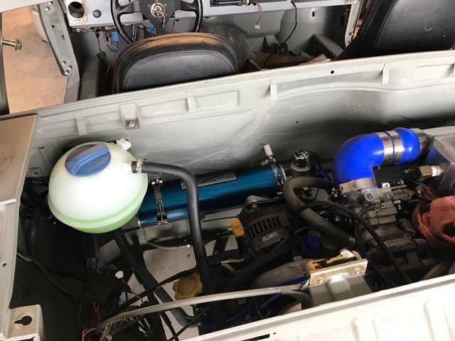
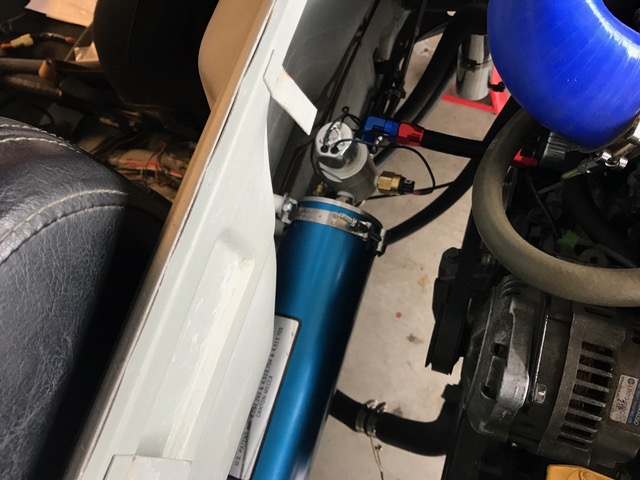
As you can see above, the Accusump oil line is only a few inches above the alternator belt, and an exploding belt could take out the oil line. So I welded up a guard using some 1/8" thick strap steel I had laying around. I'll remove it later and powdercoat it next time I've got the oven out.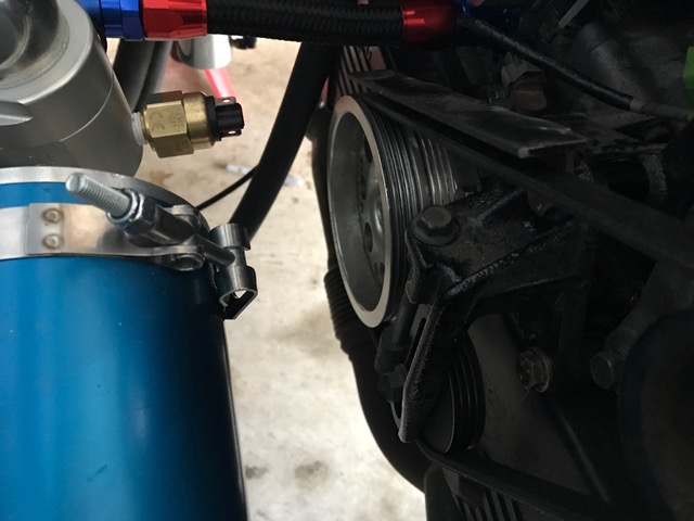
Posted by: 76-914 Feb 19 2017, 12:00 PM
Did you purchase the Bremer plate for aesthetics? I know you could have made one in 30 minutes with your eyes closed. Great build!
Posted by: strawman Feb 19 2017, 08:04 PM
Did you purchase the Bremer plate for aesthetics? I know you could have made one in 30 minutes with your eyes closed. Great build!
Ha! I bought the Bremar plate in 2008 (!!!) at the same time I bought the coupler. But you're right, I had no idea that it was so simple to build my own until I opened the box. Lesson learned and wallet lighter
By the way, I spent three hours building a hole saw jig, and 20 minutes using it to cut holes for my VDO Vision gauges (oil pressure, oil temp and EGT). Because I welded up my ashtray hole, I knew trying to use a holesaw out of the box would likely cause the tool to wander once I hit the welded up bits. I cut a 1" long piece of 1" steel rod and welded it to a round piece of 1/8" steel plate that fits inside the holesaw, and then chucked it up in my lathe to square up the face and to bore the 1/4" pilot hole. I lined this up on the dash face, and riveted it on. This ensured the holesaw didn't wander or catch too badly once it got into the welds on the backside of the dash. A picture'll do a better job than me trying to describe it... this shows the first hole completed and the jig mounted and ready for the second one.
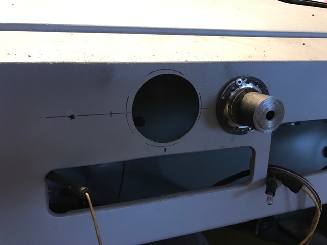
I also drilled and tapped the #3/#4 exhaust manifold and installed the EGT probe, as can be seen below. Fortunately, Subaru cast-in a nice thick "button" that provides a lot of "meat" for the threads:
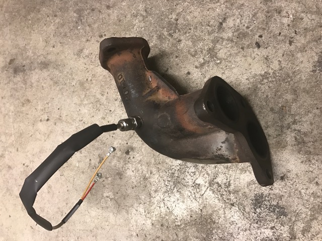
I'll spend this week connecting the gauge wiring, redoing my cable shifting setup, and calibrating the fuel gauge converter. In any case, I'm really glad I ran extra wires both to the dash and to the frunk when I assembled my wiring loom way back in 2012!
Posted by: 76-914 Feb 20 2017, 09:48 AM
Does the red locktite seal the sight glass or is there an O-ring I didn't see? Also, what diameter shift cables did you decide to use?
Posted by: charliew Feb 20 2017, 10:37 AM
One of the best things about the accusump switch is the pressurize before start up. It's neat to watch the oil pressure come up before you hit the start position on the key. I didn't see where you posted the volume of the small car pan. Is it 5 qts? Do they say it will work with hedders? At first when I changed the oil I did the pan and the accusump but after finding the accusump oil still clean I quit draining it.
Posted by: strawman Feb 20 2017, 11:57 AM
Does the red locktite seal the sight glass or is there an O-ring I didn't see? Also, what diameter shift cables did you decide to use?
No o-ring; just the red loctite. It is a very tight fit and, because the transaxle is not under pressure, I'm hoping it won't leak. I went with 1/4" shift cables. I hope I won't be disappointed in either case!
One of the best things about the accusump switch is the pressurize before start up. It's neat to watch the oil pressure come up before you hit the start position on the key. I didn't see where you posted the volume of the small car pan. Is it 5 qts? Do they say it will work with hedders? At first when I changed the oil I did the pan and the accusump but after finding the accusump oil still clean I quit draining it.
The Small Car oil pan is 5 qts. I don't know if it will interfere with headers, although their website says it is a very tight fit with their custom engine mounting system (I'm not using their mount, so I can't provide info on that, either).
Posted by: 76-914 Feb 20 2017, 12:52 PM
OK, a few more questions then I'll leave you be. Can you post a side view of the site glass? Do they recommend LockTite because I'm thinking 3 Bond sealant if I do this. Just hate those shipping charges from Down Under!
Posted by: Mueller Feb 20 2017, 02:19 PM
Great progress now that you are back working on it. Love the lift and placement for it.
Is there a particular reason for adding the accusump? Is there a known issue with those motors that warrant the extra insurance?
Posted by: charliew Feb 20 2017, 05:59 PM
A turbo suby makes hot oil and the oil will break down sooner and they are prone to using more oil than a na motor, anything you can do to keep oil to the center main and 2and 3 rod is good on a suby. If you drive a turbo suby hard you should check the oil on every other fillup in my opinion.
Posted by: strawman Feb 20 2017, 07:18 PM
Can you post a side view of the site glass? Do they recommend LockTite because I'm thinking 3 Bond sealant if I do this.
Sorry, those are the only pics I took! Go to the "Oil Levels" section at http://www.subarugears.com/FAQ/FAQ.html for more pics and a better explanation. I toyed with the idea of making my own sight glass, but figured $100 shipped to my doorstep would be "cheaper". Is that a sign of age/wisdom, or merely my wanting to finally get my car on the road?!?!?
Is there a particular reason for adding the accusump? Is there a known issue with those motors that warrant the extra insurance?
Same as in other non-dry sump flat-engines: oil collects in the outside head on a big / high-G sweeper, which can cause an air bubble in the oil pick-up system and a possible main bearing failure. This is, of course, supported scientifically through untold numbers of experts on the Internet
 . In any case, with the need for a relatively short oil pan for clearance purposes, I figured the $500 I spent on this system (I bought the 3-qt. cannister used) is a good investment and a helluva lot cheaper than ~$3k to dry-sump my Suby engine. On my BMW S52 engine in my 318ti, I welded in a Turner Motorsports oil pan baffle kit, which really helped avoid the annoying "BMW lifter tick" that occurs after a few hard autocross runs or a track session. Unfortunately, there just isn't a lot of room inside a shortened Suby pan... and I can always adapt this Accusump system should I seek a 6-cylinder Suby engine down the road.
Posted by: strawman Sep 11 2017, 11:22 AM
I spent (wasted, in 914 terms) the past seven months refinishing my hotrod BMW 318ti daily driver. I've completely upgraded the drivetrain and suspension, but it looked like poo -- the clearcoat was coming off. So I sanded it down to the primer coat, found some previous repairs, block sanded it, sprayed two coats of Calypsorot base and three coats of clear in my garage using a "booth" I built out of PVC/conduit pipe, plastic sheeting and five box fans with house filters taped on. I then finish-sanded it (1000, 1200, 2000, 2500 and 3000), followed by polishing and buffing. Of course, I gaffed a few times, and had to re-basecoat the hood, roof, passenger side rear quarter, and the driver fender. And I also had to reclear the driver side door and front fender twice. It was the first time I ever painted a car, but it came out great and served as good practice for my 914. If you're really bored, you can see the build blog at http://www.318ti.org/forum/showthread.php?t=38844
A few weeks ago, I noticed the Central Coast PCA had an autocross at the Santa Maria Airport scheduled for September 16, so I boldly signed up using my 914. With a deadline facing me, I set to work! The plan is to get it running, see what hits/rubs, work out other bugs, run a few autocrosses, strip it to the chassis again, and finish it in Pantone 172 (SF Giants color!) and black. I started by finishing up the registration process and insuring the car through Haggerty. Below is a cool pic -- the registration expired 25 years ago!
I pulled the stripped door shells from the spare bedroom, cut out the rusty door seal channel parts, welded in new pieces (PITA), and got the doors ready for epoxy primer. The driver door was especially bad, since it was dented, wavy and pockmarked. I also welded up the holes left over from the Vitaloni mirrors on both doors. I finally got the chance to use the shrinking disc I bought a few years ago, and the door blocked-out nicely with only a small skim of Evercoat Rage Extreme filler in a few places. I like using that stuff, but most of it ends up in my nose or on the ground...
If you look at Post #76 (from June 7, 2009!), you'll see the "rough" rust repairs that I made in the lower windshield area, which at the time I covered in epoxy primer. I also made rust repairs in the cowl-to-fender seam area, and ended up welding that area up -- both because of the extent of the damage and for my own aesthetic preference. Before I installed the windshield, I need to clean those areas up, smooth 'em, and then reapply epoxy primer. After letting it all dry/cure, I pulled the old PPG windshield out of the attic and test-fitted it. Gawdammit, the windshield hits my fender-flare inspired dash pod! 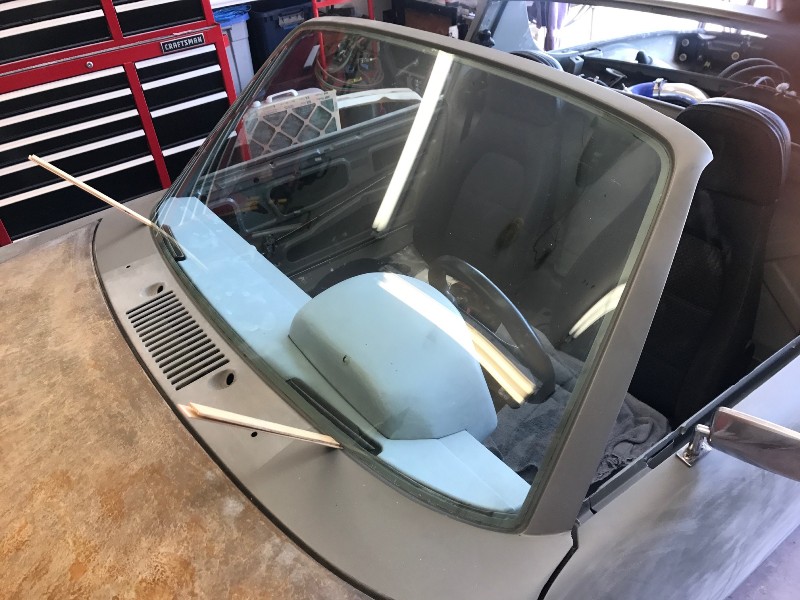
Out came the rasp file and sanding blocks. I now have about 3/16" clearance, but I am now worried it'll affect defrosting. When I pull everything apart for paint, I'll reconfigure the pod. I used 3M butyl tape in 5/16" using instructions I found on this site. Everything went well, although when I install the new windshield I'll place the butyl bead on the inside edge of the pinchweld.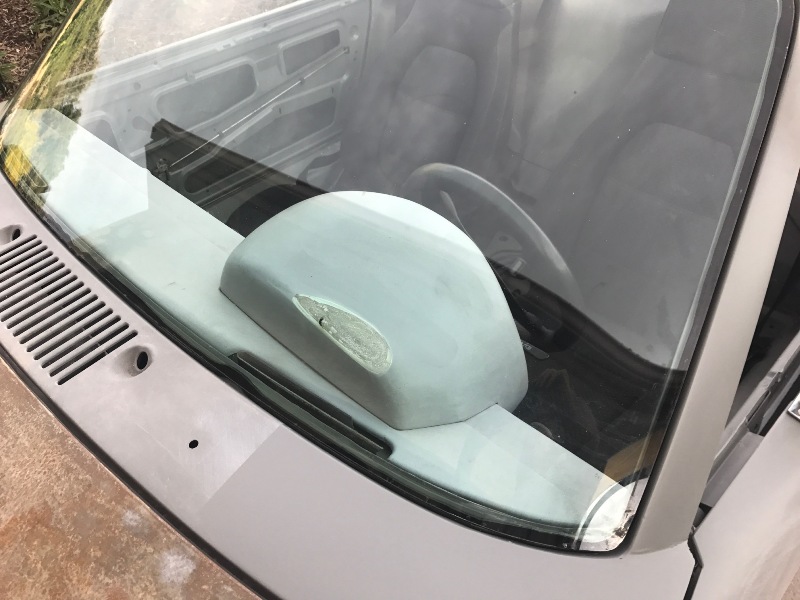
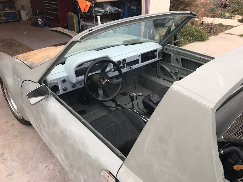
I installed the headlights, doors (without any rubber seals for now), trunk lid and engine lid, and I took it for its first real set of several test-drives. Nothing rubs or grinds (yay!), although the turbo is not producing boost (boo!). And the doors really rattle without the rubber seals! The brakes work great, and my Frankenstein steering system (see post #84) is tight. It is REALLY loud; I set off the alarm on a neighbor's Prius twice on the first two trips around the block. I'll need to rethink the exhaust...
The H-pattern shift system is balky -- especially 3rd gear. From second gear, I have to move the lever up, to the right, and then sorta left-n-up toward first gear. I'll see how the adjustments in the cable mounts changes the pattern.
I strapped on my string-box alignment setup (see below) and found that front is toed-out a total of 1", so I'll align it tonight.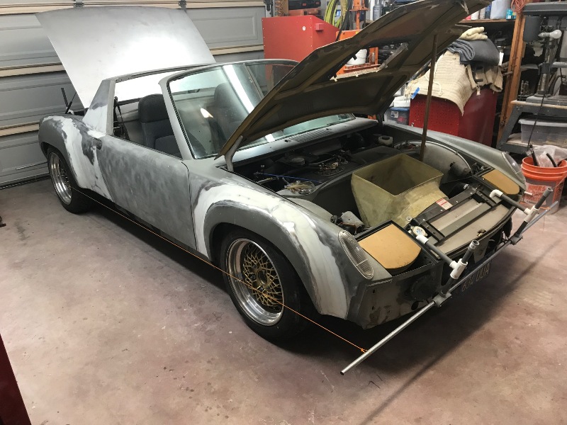
I need to drive it as much as possible this week to figure out its weaknesses before the race on Saturday. I really don't care too much about the boost at this point, since I'll use the autocross more as a testing platform than a competition.
Posted by: 76-914 Sep 11 2017, 11:51 AM
Good to see you back on it!
Posted by: charliew Sep 11 2017, 12:59 PM
still following along on your great build. I went back to refresh on the previous page and noticed the windage tray on your motor and I must have 5 different 4cyl suby shortblocks and I've never seen a tray like that one it is a lot different from the ones I have, also it has a great oil pickup support.
Posted by: JRust Sep 11 2017, 01:57 PM
Nice bud. Can't wait to hear how the autocross goes. I can't think of a better way to test it out
Posted by: strawman Sep 11 2017, 02:21 PM
The rain seems to have gone away, so I went home for lunch and drove the 914 to work. I manage the regional public transit system here in SLO. All the mechanics at my office came out to the parking lot and were crawling all over it -- the best ego boost an executive director can get.
Posted by: strawman Sep 18 2017, 10:47 AM
First tow!!!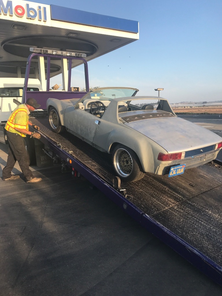
The car had been working reasonably well, although the shifting kept getting balkier, especially 5th and Reverse. The turbo is also not boosting, so it was not accelerating particularly hard. But I had already paid for the September 16th PCA Zone 8 autocross, so I entered it anyway and took the car for its longest-yet drive to Santa Maria. The drive down was uneventful though a little chilly. The course was relatively wide open, with two fun slaloms and a fast finish. There were three other 914s (a pristine '74 2.0, a highly-modified 914-6, and a hashed out '72 1.7), and all ran best times of between 66 and 73 seconds in the first run group. Out of the box, I ran a 68.356 although my car stalled off the line and coughed at every shift. In short, it handles great and can carry speed through turns that would cause my BMW 332ti to blow through a wall of cones.
Coolant temps climbed right before my last two of five runs, but the big-ass Lincoln fan kicked in and cooled it right back down. My oil temps also started to climb to about 210 degrees (more on that later...). I ended my fifth run with a clean 67.057, which isn't too bad considering the 914-6 was on Hoosiers and was less than 2 seconds faster.
Right before my next set of runs in the afternoon, I started the car up and my dash-mounted oil pressure gauge showed less than 10 psi at idle, and would not climb past 20 psi. A check of the mechanical gauge on my Accusump confirmed it. Oil level was fine, so I parked it for the day. I figured I could nurse it the 30 miles home, and I vigilantly watched the oil pressure, oil temp and coolant temp gauges, while only going 65mph on US-101 -- which is a bit terrifying as huge SUVs raced past me! I made it about three miles when the oil pressure dropped below 10 and the idiot light in the Suby dash (set at 7 psi) began to flicker. I quickly pulled off at the nearby interchange, and when I backed into a parking spot at the Mobil gas station, my gear lever was stuck. Uh oh, two bad things are now happening. I called Hagerty Roadside Assistance, and the picture above shows the result.
Yesterday, I got the car up on the lift, pulled the oil filter, used a paint filter cone to check for metal pieces and found nothing. I cut open the filter and unfurled the filter media (what a messy job!). I found no metal or other debris. I then drained the oil through a paint cone filter, and again found no debris. I pulled the sump and discovered the problem right away: I AM A MORON
In bottom of the sump was an oil soaked Scott's blue shop towel! I remember tucking a towel up in a crevice to help sop up oil when cleaning the surface to ready it for RTV when I installed the SmallCar sump, and obviously I forgot to remove it. The high-Gs pulled at the autocross must have dislodged it and it sucked up against the oil pick-up screen, robbing the engine of oil.
I buttoned up everything (all towels accounted for ), filled it up with another 8 quarts of Shell Rotella T6, and the pressure was back to good at both idle and when revving it up. Hopefully, I didn't cause any long-term damage.
I pulled the Subaru transaxle last night, and I'll provide a post-mortem on it in the next couple of days. The long-n-short of it is I had planned to swap out the Phase I 5MT for a Phase II that was already sitting in my garage, but now I'm forced to do it to get the car back on the road. The Suby transmissions are somewhat notorious for bent shift forks, and a common upgrade is to use later-model steel forks in place of the earlier aluminum ones. Internet lore states that this is compounded in the Phase I units that depend upon the (now removed) center differential for oiling; the Phase II units use 5th gear for splashing gear oil. The Phase II transaxles also apparently have a stronger case. More info on the preferred Suby transaxle for a mid-engine swap can be found http://thefactoryfiveforum.com/showthread.php?9909-THE-Transmission-Thread-2-0-Now-with-Pictures&p=97665&viewfull=1#post97665.
I had to pull the downpipe/muffler to remove the trans, and I figured out why no I'm getting no boost -- the turbo exhaust impeller is partially bound up. I know what you're thinking: maybe he left a rag in the intake of the turbo. Yes, I deserve that. 
I also need to replace the cracking CV boots (that I replaced with new aftermarket ones in 2011!). Finally, my in-tank fuel pump is audibly whining, so I'll need to replace it with a new Walbro 255 l/hr unit. Fun, fun, fun...
Posted by: theer Sep 18 2017, 12:05 PM
HA! those darn blue towels. They will also prevent your carb'ed motor from running properly if you leave them in the intake when you re-install the carbs.
Yup, I did that. Fortunately, only on one side. Took me two hours to fish the paper bits back out through the intakes and spark plug holes. To quote Bugs Bunny: "what a maroon."
That's all folks - and now back to the regularly scheduled program...
Posted by: 76-914 Sep 18 2017, 01:24 PM
We all do it. I once left a paring knife (making gaskets) on top of the cam in an old hot rod. I'm glad nothing major happened to your car.
Posted by: strawman Oct 6 2017, 12:33 PM
Okay, I discovered the reason why my Phase I Suby transaxle locked up: the reverse countergear shaft drifted and tweaked the case (and, again, I'm a moron). I discovered this when I was assembling the replacement Phase II trans, when the new input shaft bearing's locating pin interfered with the reverse gear shaft locking pin. I didn't know that the locating pin on the new bearing could be removed and that the locking pin would both lock the reverse shaft and locate the new bearing . It was likely exacerbated by the fact that the Phase I transaxles are not lubricated correctly once you remove the center differential to use in a mid-engine scenario, whereas the Phase II units are lubed independently. Hard to describe -- but if you're rebuilding a Suby transaxle, use Vise-Grips to remove the locating pin from the new input bearing, don't cavalierly toss the locking pin, and use a Phase II transaxle from the get-go (they also seem to have beefier shift forks). There's a lot of great info now available on the Factory Five 818 discussion board that wasn't available when I started this project.
The Phase II trans also has eight size M10 engine-trans mount holes, whereas the Phase I has only four. While four of the eight holes line up perfectly with the earlier engines, this is a problem because the later engines use two through-bolts to mount the starter; the Phase I transaxles use one M10-1.25 stud and one M10 through-bolt. The best solution would have been to install an M10-1.25 Heli-Coil into one of the eight holes and twist in a stud, but I didn't want to buy a $65 Heli-Coil kit when it would be cheap-n-easy to drill/tap for an M12-1.25 stud. Instead of drilling a larger hole in the starter, I chucked up an M12 stud in my HF lathe to step it down to accept an M10-1.25 nut.
The Phase II transaxle is now in the car, after first updating the hardware in the OBX limited-slip -- a common upgrade that I learned of after originally installing in the Phase I transaxle . It is less yhan $30 shipped, which can be found at http://rbryant.freeshell.org/obx_washers.htm. The gearing is slightly higher in the Phase II trans (final drive 3.90 vs. 4.11), but that should be better since the Phase I was a little low for my liking -- I had to shift from 1st gear almost immediately after taking off. If anyone is undertaking a Suby trans overhall, PM me and I'll ship the jig I built that holds it steady while setting the backlash...
I am using a "secret sauce" that is generally lauded on the Factory Five 818 forum: one quart each of Pennzoil Synchromesh and Red Line Heavy Shockproof, and two quarts of Castrol Limited Slip 80W-90. 
One other thing that I had to redo: replace the el-cheapo Dorman inner CV boots I used a few year ago when I assembled the hybrid axles. The boots were badly weather-checked and splitting (turning to powder!) despite having fewer than a couple hundred miles on 'em. Do yourself a favor and buy Subaru boots -- they're made of noticeably thicker and higher-quality rubber, and they were less than $20 each.
I locally sourced a used TD04L-13T turbo from a 2002-04 WRX, since my original TD05H-16G that came with my engine developed a lot of shaft play / binding and the up-pipe flange is cracked. The TD04 should also spool up faster than the larger TD05, but it'll poop out earlier in the RPM range. It'll be hard for me to compare, since my TD05 didn't boost anyway. I paid $80 for the used TD04 turbo and $60 shipped for a rebuild kit from Turbo Lab of America, plus another $40 for gaskets and new coolant pipes. I separated the housings last night on the TD04 and will rebuild the center cartridge over the weekend. Some say it must be rebalanced; others say as long as the turbines did not make contact with either housing, you can carefully mark their relative positions and buckle it back up. I chose the latter since there are no shiny spots. I also need to slightly reconfigure my turbo inlet piping/hoses, since the TD05H has a slightly unorthodox 90 degree inlet casting. Hopefully, I'll be able to drive it (with boost ) before the weekend is over and the turbo won't spin itself into unbalanced oblivion... 
Posted by: 914forme Oct 6 2017, 06:58 PM
Thank you for the great info and hunting it down
Also do you have a picture of the jig? shipping on it can be a few $$$.
And I would love to get my OBX in my trans.
Nice build on the 318ti
Posted by: strawman Oct 7 2017, 02:34 PM
Also do you have a picture of the jig? shipping on it can be a few $$$.
A great set of instructions is included at http://thefactoryfiveforum.com/showthread.php?16706-Limited-slip-installation-instructions-with-pics. I cut/pasted all of that info into an MS Word document; PM with your email addy and I'll send the 6MB file. The instructions say to use pieces of wood and shims to steady the trans while setting the backlash, but below is a pic of the scrap metal jig I built to keep it rock-solid -- I don't think it'd cost much to ship and it'd be yours to keep/pass-on. I also used an HF slide hammer screwed into a set of Vise-Grips to keep the shaft from moving (the pics in the attached link will help this make sense).
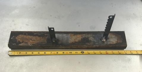
Posted by: strawman Oct 7 2017, 02:50 PM
Oh, and everything is mounted up now. However, I had to order a https://www.performancebyie.com/integrated-engineering-silicone-90-degree-cobra-head-coupler-2-5-to-2-5 to clear the intake manifold, as well as a couple of http://www.rockauto.com/en/moreinfo.php?pk=6401286 to mate up the 2.5" cobra-head to my 2.25" OD turbo inlet and aluminum piping. So it'll be next weekend before these are shipped and I can get it running. Here's some pics of these pieces for reference:
Posted by: 98101 Oct 7 2017, 08:57 PM
In bottom of the sump was an oil soaked Scott's blue shop towel!
This made me smile.
Posted by: charliew Oct 9 2017, 12:20 PM
a few years ago I studied every tranny lube thread I could find on the suby but it was mainly for the 6 sp as my son's sti scratched 5th at wot every time since new. we tried different lubes and decided it was fruitless. while I was searching it was said that you could get too slippery and the syncros could not let the gears settle on a even speed while engaging. the only way I can see to really know is of course trial and error. just like the trial and error of the fluid level after changing the rear to 2wd. the age and mileage on the syncros is also a determining factor on how well the syncros work i'm sure. At any rate you are giving everyone a great deal of good experience related advice on starting out on your adventure. I also have started with a 96 outback turbo tranny which is a ph1 and have already put the locker and bremar stuff in it a long time back. I also at the time thought the 4:11 was too low for the torque range of the turbo suby but that was my first tranny buy as it came with the motor. I guess I will move the new parts to a 05 tranny I bought on ebay a few years ago. Do you turn the key on to drain the accusump as that's the way I do the on the one in my blazer when I change the oil? I am interested if yours completely drains on it's side like that.
Posted by: strawman Mar 11 2018, 08:51 PM
Well, I finally sold one of my sidetracks -- the M3-swapped 318ti is now at its new home in Ohio.
As soon as the funds hit my bank account, I ordered a RobTune chipped ECU originally from a JDM WRX STI, a set of '04 USDM WRX STI injectors from eBay, a set of RobTune injector adaptors, and a RobTune coil-pack adaptor kit. All told, this stuff cost me a grand. After repinning a few ECU wires and installing everything, it fired right up. And man does it boost hard now!
I've conservatively set the boost at 12psi for now (using the HKS electronic boost controller that I got from JCD914 a few years ago) while I log a few runs to monitor my air-fuel ratio and EGT readings. My next autocross is March 24th, so I'll spent the next few days testing and tuning.
It is exciting to finally get this car running the way it should! It is easy to break the tires loose in first and second gear, and it hisses and blows like a hurricane.
Posted by: JRust Mar 12 2018, 02:55 PM
Love it man. Getting close with mine but has been a slow swap for sure. Post some bideo of it now with the boos working. I need to hear that thing howl
Posted by: Justinp71 Mar 13 2018, 12:03 AM
Well, I finally sold one of my sidetracks -- the M3-swapped 318ti is now at its new home in Ohio.
As soon as the funds hit my bank account, I ordered a RobTune chipped ECU originally from a JDM WRX STI, a set of '04 USDM WRX STI injectors from eBay, a set of RobTune injector adaptors, and a RobTune coil-pack adaptor kit. All told, this stuff cost me a grand. After repinning a few ECU wires and installing everything, it fired right up. And man does it boost hard now!
I've conservatively set the boost at 12psi for now (using the HKS electronic boost controller that I got from JCD914 a few years ago) while I log a few runs to monitor my air-fuel ratio and EGT readings. My next autocross is March 24th, so I'll spent the next few days testing and tuning.
It is exciting to finally get this car running the way it should! It is easy to break the tires loose in first and second gear, and it hisses and blows like a hurricane.
Nice to see your still working on it!
So for computer, you did factory wiring with an aftermarket ecu? Can you share your cost vs build time? I'm doing a EJ25 into my off-road car at the moment and weighing the different ecu/wiring options.
Posted by: strawman Mar 13 2018, 05:31 PM
Nice to see your still working on it!
So for computer, you did factory wiring with an aftermarket ecu? Can you share your cost vs build time? I'm doing a EJ25 into my off-road car at the moment and weighing the different ecu/wiring options.
Hi Justin,
If you're doing an EJ25D swap, I would recommend a factory ECU and wiring (or an aftermarket Stinger if you're going to turbo it). The factory stuff works really well, unless you plan to modify the fuel maps, use forced induction or mess with other parameters; it almost always starts regardless of the weather or elevation.
I originally used an EJ22T (2.2 liter SOHC) engine out of a 91-94 Subaru Legacy, including all factory Subaru sensors, ECU and wiring. I spent a lot of hours studying the 914 and Subaru wiring diagrams, cutting out unnecessary wires, and connecting the ones that needed to flow electrons. I also am using a Subaru dash cluster out of a 1999 Subaru Forester. While that setup ran reasonably well, it had trouble with the larger turbo and slightly bigger injectors (440cc JDM EJ20G vs. 370cc USDM EJ22T) that I installed. I wired in an electronic "clamp" -- sometimes referred to as a Fuel Cut Defencer -- to allow higher turbo boost without hitting the factory boost (9 psi) fuel-cut prematurely, but it was not consistent and often caused the car to fall flat on its face when accelerating.
RobTune adapts the ECU out of a mid- to late-90s JDM WRX STI for use on an EJ22T engine and harness; that ECU and the EJ22T ECU both use the same factory four-plug ECU wiring harness. He installs a custom chip, based on a modest list of options (fuel injectors sizing, turbo, exhaust, etc.) and entirely removes the factory fuel cut -- which means an aftermarket boost controller is needed. I bought a JDM ECU off of eBay for $80, and bought a set of yellow-top USDM STI injectors for $150 (rebuilt, including spec sheets) on eBay. I then shipped the ECU to Rob to install his chip for $325, paid $90 for the coil conversion, and $70 for injector adaptors. Using his instructions, I repinned a few wires and voila -- it runs great. Based on dyno runs of RobTune-modified cars, my engine should put out between 250 and 275 horsepower.
The advantage of the EJ22T is that the block is closed-deck -- so it will take a lot of boost without blowing head gaskets. The disadvantage is the SOHC heads; Internet Lore says they poop-out above 5000 rpm, but mine seems to pull strong to the new RobTune 7100 rpm redline. DOHC EJ25D or EJ20 heads & intake manifold bolt right on the EJ22T block if I ever decide to make the engine breathe better. Honestly, if I blow up this engine, I'll likely just install an EJ257 and get a factory 300hp setup with easier tuning abilities...
Good luck with your project!
Geoff
Posted by: charliew Mar 13 2018, 05:49 PM
Nice to see your still working on it!
So for computer, you did factory wiring with an aftermarket ecu? Can you share your cost vs build time? I'm doing a EJ25 into my off-road car at the moment and weighing the different ecu/wiring options.
Hi Justin,
If you're doing an EJ25D swap, I would recommend a factory ECU and wiring (or an aftermarket Stinger if you're going to turbo it). The factory stuff works really well, unless you plan to modify the fuel maps, use forced induction or mess with other parameters; it almost always starts regardless of the weather or elevation.
I originally used an EJ22T (2.2 liter SOHC) engine out of a 91-94 Subaru Legacy, including all factory Subaru sensors, ECU and wiring. I spent a lot of hours studying the 914 and Subaru wiring diagrams, cutting out unnecessary wires, and connecting the ones that needed to flow electrons. I also am using a Subaru dash cluster out of a 1999 Subaru Forester. While that setup ran reasonably well, it had trouble with the larger turbo and slightly bigger injectors (440cc JDM EJ20G vs. 370cc USDM EJ22T) that I installed. I wired in an electronic "clamp" -- sometimes referred to as a Fuel Cut Defencer -- to allow higher turbo boost without hitting the factory boost (9 psi) fuel-cut prematurely, but it was not consistent and often caused the car to fall flat on its face when accelerating.
RobTune adapts the ECU out of a mid- to late-90s JDM WRX STI for use on an EJ22T engine and harness; that ECU and the EJ22T ECU both use the same factory four-plug ECU wiring harness. He installs a custom chip, based on a modest list of options (fuel injectors sizing, turbo, exhaust, etc.) and entirely removes the factory fuel cut -- which means an aftermarket boost controller is needed. I bought a JDM ECU off of eBay for $80, and bought a set of yellow-top USDM STI injectors for $150 (rebuilt, including spec sheets) on eBay. I then shipped the ECU to Rob to install his chip for $325, paid $90 for the coil conversion, and $70 for injector adaptors. Using his instructions, I repinned a few wires and voila -- it runs great. Based on dyno runs of RobTune-modified cars, my engine should put out between 250 and 275 horsepower.
The advantage of the EJ22T is that the block is closed-deck -- so it will take a lot of boost without blowing head gaskets. The disadvantage is the SOHC heads; Internet Lore says they poop-out above 5000 rpm, but mine seems to pull strong to the new RobTune 7100 rpm redline. DOHC EJ25D or EJ20 heads & intake manifold bolt right on the EJ22T block if I ever decide to make the engine breathe better. Honestly, if I blow up this engine, I'll likely just install an EJ257 and get a factory 300hp setup with easier tuning abilities...
Good luck with your project!
Geoff
Geoff you know your closed deck block might still be worth 500 or so. I haven't been on nasioc for quite awhile but closed deck blocks used to be pretty desirable for high boost. built motors. I bought a 2.0 closed deck short block a long time ago but don't know if I will ever get to using it at this time in my journey.
Posted by: strawman May 2 2018, 06:27 PM
I entered my 914 into its second PCA autocross in Santa Maria on March 24th. It handled and shifted great, and all engine vitals were perfect. But the failing fuel pump got worse and wouldn't let the engine rev above 4k under boost. But despite short-shifting it and driving on street tires (Dunlop Direzza), I finished in the top 20%.
When I got home, I tested the fuel pressure and verified the problem: it wouldn't go over 30psi. The backstory is (because I'm a cheap bastard) I originally installed a used Walbro 255 lph pump that I found on Craigslist back in 2010. I finally installed a new Walbro 255 pump a couple of weeks ago and it now pulls strongly up to the 7k rpm redline.
I entered another PCA autocross in Santa Maria on April 28th, and I believe I finished in the top 10% (final times still not posted). For sure, I beat some guys in my run group this time who were ahead of me last time. The event was cut short due to an idiot (Cayman GT4) who totally overcooked a turn and spun-out into a bystander. I'll never be able to unsee that...  I just hope she fully recovers from her considerable injuries soon.
I also installed a set of new/aftermarket retractable seat belts from SeatBeltPlanet, but at some point I need to install a harness so I'm not thrown around the seat in high-g corners. I'm currently using NA Miata cloth seats (again: cheap bastard) so a racing seat might also be in my future. In any case, the new seat belts at ~$240 is some of the best money I've spent, since my wife will not guffaw at me every time she gets in my car...
I plan to race a Vapor Trails Corvette autocross on May 12th, so I'll see how I do against the big iron. I'll try to mount up my daughter's GoPro for that event, and I'll post a video or two. Stay tuned (pun intended!).
Posted by: charliew May 2 2018, 07:01 PM
I entered my 914 into its second PCA autocross in Santa Maria on March 24th. It handled and shifted great, and all engine vitals were perfect. But the failing fuel pump got worse and wouldn't let the engine rev above 4k under boost. But despite short-shifting it and driving on street tires (Dunlop Direzza), I finished in the top 20%.
When I got home, I tested the fuel pressure and verified the problem: it wouldn't go over 30psi. The backstory is (because I'm a cheap bastard) I originally installed a used Walbro 255 lph pump that I found on Craigslist back in 2010. I finally installed a new Walbro 255 pump a couple of weeks ago and it now pulls strongly up to the 7k rpm redline.
I entered another PCA autocross in Santa Maria on April 28th, and I believe I finished in the top 10% (final times still not posted). For sure, I beat some guys in my run group this time who were ahead of me last time. The event was cut short due to an idiot (Cayman GT4) who totally overcooked a turn and spun-out into a bystander. I'll never be able to unsee that...
I just hope she fully recovers from her considerable injuries soon.I also installed a set of new/aftermarket retractable seat belts from SeatBeltPlanet, but at some point I need to install a harness so I'm not thrown around the seat in high-g corners. I'm currently using NA Miata cloth seats (again: cheap bastard) so a racing seat might also be in my future. In any case, the new seat belts at ~$240 is some of the best money I've spent, since my wife will not guffaw at me every time she gets in my car...
I plan to race a Vapor Trails Corvette autocross on May 12th, so I'll see how I do against the big iron. I'll try to mount up my daughter's GoPro for that event, and I'll post a video or two. Stay tuned (pun intended!).
you are doing something I always wanted to do but never had the guts or car for it. I know you are having the time of your life.
Is this the hybrid motor? 2.5 with early heads or 2.0 wrx heads and small turbo?
sorry to hyjack guys
charliew
Posted by: 914forme May 2 2018, 07:30 PM
you are doing something I always wanted to do but never had the guts or car for it. I know you are having the time of your life.
Is this the hybrid motor? 2.5 with early heads or 2.0 wrx heads and small turbo?
sorry to hyjack guys
charliew
Not get off topic, but you can auto-x any car. We had a guy here back in the 80s at auto-xed a Yugo. I have seen pickup trucks to shifter carts, to a Porsche 936 driven by Derek Bell. I have also watched Mr. Bell do a 360 in the middle of a run to miss the wall and recover to lay down a very great time.
Point being you can take any car, you can learn from it, and have a great time. One of the best times I ever had was in a $900 dollar Miata we bought, fixed the EFI flapper valve with a bit of WD 40 took it out to the event on rock hard 14s, and just drifted the piss out of that Miata. No where near the fastest time, but man was it fun driving almost the entire corse sideways. Gave that little 1.6L all sorts of hell.
Hell I used to take a 1998 VW TDI ( yep a diesel) and auto-x'd it had a blast. Would tell the starter to take a few steps back, because that car rolled the coal.
Go try it, drive what ever you have, and have fun.
Posted by: strawman May 12 2018, 09:22 PM
I was really enjoying the added power at a Vapor Trails Corvette club autocross today, and even with street tires I was hanging with some very fast cars. Unfortunately, I never got around to borrowing my daughter's GoPro, so no videos. On my fourth run, I decided to launch a little harder... big mistake. I usually launch at 3,500 rpms, but thought I could amp it up a bit and I launched at 5k. Bang! I pulled to the side of the track and quickly realized that things were not right on the transaxle end of my passenger side axle.
Below is a pic of the Subaru "tripod" joint after peeling back the rubber boot, followed by a pic of the failed part. These are stock 1976 911 axles that I had shortened and resplined by Dutchman for the Subaru joint. Major twistage failure.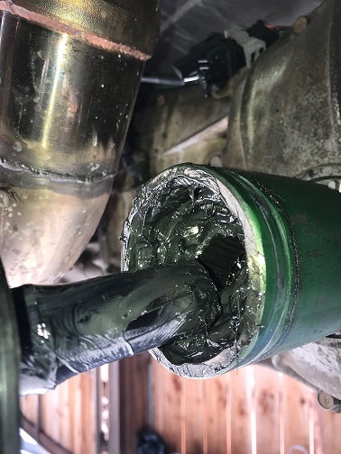
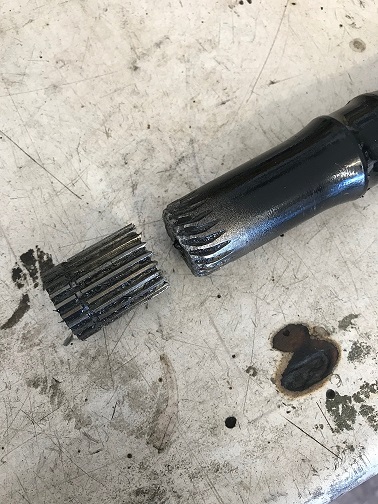
I honestly thought the inner Subaru tripod or outer 911 CV would act as the fuse, but obviously I was wrong. I will call Dutchman on Monday to see what my options are. I might spring for a set of 4340 Cro-Mo or Hy-Tuf custom shafts, depending upon price.
Posted by: 914forme May 13 2018, 08:37 AM
Bummer on the failure, but now you know.
Did a V8 swap into a Olds Bravada once, the AWD SUV, it was hast as hell! But you would fix one thing and the next would break. Took pieces to the drive line guys and they said what are you building a rolling dyno. And I guess he was 100% correct. I was building a torture test device for each part of the driveline.
What I am shocked about is you generated enough shock to shear the axle like that on street tires. That is pretty impressive
Are you running an LSD? I forget
BTW, your harder launch was most likely the driving force to nail in the coffin. I am beating that you twisted it a bit on each run. And that axle might not have been hardened again after the splining process. My engineering curiosity would love to see the other side, especially if you have an LSD. You should see similar damage to the other axle unless one side is defective.
Posted by: 76-914 May 13 2018, 08:57 AM
I was really enjoying the added power at a Vapor Trails Corvette club autocross today, and even with street tires I was hanging with some very fast cars. Unfortunately, I never got around to borrowing my daughter's GoPro, so no videos. On my fourth run, I decided to launch a little harder... big mistake. I usually launch at 3,500 rpms, but thought I could amp it up a bit and I launched at 5k. Bang! I pulled to the side of the track and quickly realized that things were not right on the transaxle end of my passenger side axle.
Below is a pic of the Subaru "tripod" joint after peeling back the rubber boot, followed by a pic of the failed part. These are stock 1976 911 axles that I had shortened and resplined by Dutchman for the Subaru joint. Major twistage failure.
I honestly thought the inner Subaru tripod or outer 911 CV would act as the fuse, but obviously I was wrong. I will call Dutchman on Monday to see what my options are. I might spring for a set of 4340 Cro-Mo or Hy-Tuf custom shafts, depending upon price.
Damn!

Posted by: charliew May 13 2018, 09:55 AM
I guess you could feather the clutch till it gets rolling and maybe get by on another set like these. It will be interesting to see if the swayaway axles some of us have bought will hold up any better. are the tires 8 inches wide? and I guess the ratio is 390 or 370? 02 or 05 tranny? It's probably all in your thread way back aways. I'm glad you are testing all this for everyone. I gues the one good thing was the axle didn't wipe out the stuff around it when it broke, it stayed inside the cv joint.
Posted by: effutuo101 May 13 2018, 10:55 AM
Wow! Following this!
Posted by: Chris H. May 13 2018, 11:17 AM
The AXLE broke???? Wow. First one I've heard of. At least it broke on the trans end. Otherwise it could have gotten loose and beat the crap out of everything around it.
Posted by: tazz9924 May 13 2018, 06:25 PM
I had the exact same problem, broke the axle in half on the suby side, but it also blew up the Porsche joint at the same time  I just had another axle resplined and i live on and slip the clutch on. One day ill get some 4340’s
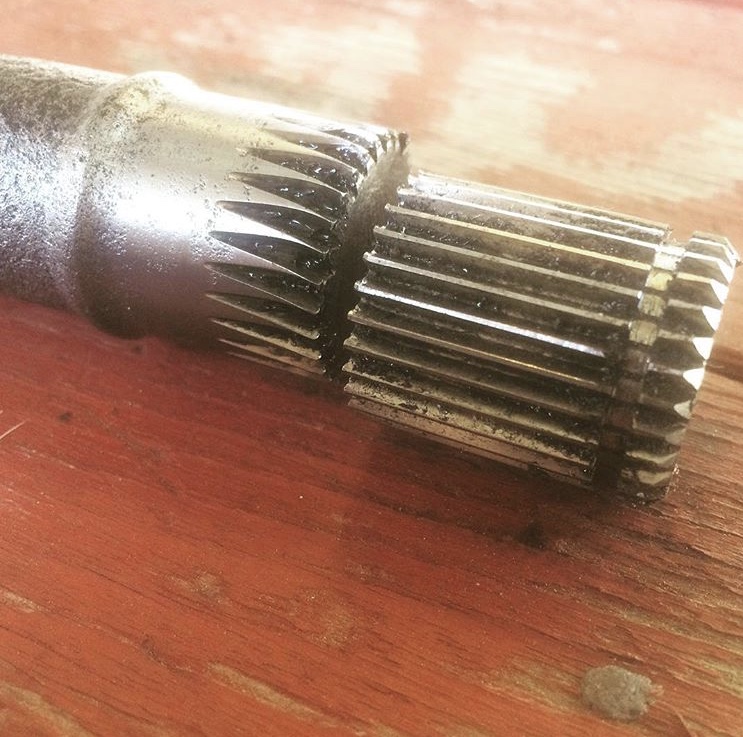
Posted by: strawman May 14 2018, 10:42 AM
I just got off the phone with Derrick at Dutchman Axles. I will be sending in my mock-up axle (see post #179) and the two "female" CV pieces in the next day or two. I'm going with Hy-Tuf material for $585 for the pair; turnaround is about a week. Stay tuned!
Also, because I'm a glutton for punishment, I just bought a wrecked 2005 Legacy GT with 104k miles and a brand new turbo. The EJ255 engine comes stock with 250hp, but it is much easier to tune than the old OBD-I currently in my car. I'll start posting pics once I haul the carcass home.
I have a VERY patient wife...
Posted by: strawman May 14 2018, 10:48 AM
Are you running an LSD? I forget
BTW, your harder launch was most likely the driving force to nail in the coffin. I am beating that you twisted it a bit on each run. And that axle might not have been hardened again after the splining process. My engineering curiosity would love to see the other side, especially if you have an LSD. You should see similar damage to the other axle unless one side is defective.
Yes, I am running an OBX helical-gear LSD in the Suby 5-speed transaxle. My tires are Dunlop Direzza 225/45-16 in 200 treadwear -- sticky, but not R-comps (yet!). You're right that the shafts might have been fatigued, but from what I have read the axles should act as somewhat of a torsion -- accept some twist to take the shock out of the system. It seems like I added a little too much twist! I never asked Dutchman if they heat-treated 'em after they shortened & resplined 'em. The new Hy-Tuf axles will likely expose the next weakest link downstream...
Posted by: strawman May 14 2018, 10:50 AM
I had the exact same problem, broke the axle in half on the suby side, but it also blew up the Porsche joint at the same time
I just had another axle resplined and i live on and slip the clutch on. One day ill get some 4340’sLooks familiar
Did your axle break due to a hard launch? Dutchman recommends their Hy-Tuf material over the 4340s. I didn't ask about any price differential...Posted by: charliew May 14 2018, 10:57 AM
I wonder what the difference is in the legacy and the sti? I remember the only autocross my son did at the track in ft worth there were several legacys there also. The vvt will give a lot more torque down low plus the 2.5l so even the stock tune should take awhile to get used to. I would drop the pan and see whats in the bottom even if you don't change it out for a better one for autoxing. maybe put a new belt on it too. there is lots of info as you probably already know on tuning open source. it will be interesting to see if you think you need more than what it already is. my son sold his 05 sti to someone in ft worth that bought it just for racing after my son took him for a ride in it. that last dyno was 498 at the wheels with e85 and a big turbo with lots of mods. course that is a 3400 lb awd car. your little hotrod will be a little over 1/2 that so the performance should be something but you also will have more low end torque with the smaller valves and smaller more responsive turbo. I am anxious to see how this goes. the legacy will probably be 3.54? I think from memory, ratio which will put more strain on the driveline but be a real nice ratio for a light car. I forgot the legacy is a 6 spd, you can recoup a lot of your cost just selling the driveline on nasioc. I know it's a lot of work and cost but if you could scoot the motor forward and squeeze the 6 speed in, it would be one of a kind but actually the first gear is really just for getting the car moving and you really don't need a gear that low in the 914. my son's 6 speed always scratched 5th at 6500 or 7k since it was new, I think the salesman screwed it up demoing it to kids before my son bought it.
you know Scott has the same wiring on his porsti so he can give lots of info on the harness.
I just thought of something else, you might send a oil sample off and see whats in the oil to check the motors condition.
Posted by: strawman May 14 2018, 10:58 AM
I guess you could feather the clutch till it gets rolling and maybe get by on another set like these. It will be interesting to see if the swayaway axles some of us have bought will hold up any better. are the tires 8 inches wide? and I guess the ratio is 390 or 370? 02 or 05 tranny? It's probably all in your thread way back aways. I'm glad you are testing all this for everyone. I gues the one good thing was the axle didn't wipe out the stuff around it when it broke, it stayed inside the cv joint.
Feathering would imply I have talent
but I WENT FOR IT instead...My neighbor across the street runs a big-dollars LS1/Mendeola-equipped desert buggy, and he has nothing good to say about Sway-A-Way axles. In fact, he calls them StayAway. After breaking a couple, he had custom ones built by Dutchman and hasn't broken one yet.
My transaxle is a Phase II out of a 2001 Outback with 3.90 final drive. Unfortunately, the wrecked Legacy GT I just bought has a slushbox - so I will reuse the manual one already in my teener.
Posted by: jd74914 May 14 2018, 11:26 AM
I had the exact same problem, broke the axle in half on the suby side, but it also blew up the Porsche joint at the same time
I just had another axle resplined and i live on and slip the clutch on. One day ill get some 4340’sLooks familiar
Did your axle break due to a hard launch? Dutchman recommends their Hy-Tuf material over the 4340s. I didn't ask about any price differential...The problem is likely that they did not re-heat treat after the cut. The OEM axles are only treated to a certain depth and the new spline roots are likely far below that depth.
I had the exact same failure on a car with recut splines on an open wheeled racecar a few years ago. It was actually a little worse in that the axle longitudinally split to relieve stress at the same time. The next time we sent them to heat treat after cutting and never had another failure.
Posted by: Mueller May 14 2018, 12:57 PM
I guess you could feather the clutch till it gets rolling and maybe get by on another set like these. It will be interesting to see if the swayaway axles some of us have bought will hold up any better. are the tires 8 inches wide? and I guess the ratio is 390 or 370? 02 or 05 tranny? It's probably all in your thread way back aways. I'm glad you are testing all this for everyone. I gues the one good thing was the axle didn't wipe out the stuff around it when it broke, it stayed inside the cv joint.
Feathering would imply I have talent
but I WENT FOR IT instead...My neighbor across the street runs a big-dollars LS1/Mendeola-equipped desert buggy, and he has nothing good to say about Sway-A-Way axles. In fact, he calls them StayAway. After breaking a couple, he had custom ones built by Dutchman and hasn't broken one yet.
My transaxle is a Phase II out of a 2003 Outback with 3.90 final drive. Unfortunately, the wrecked Legacy GT I just bought has a slushbox - so I will reuse the manual one already in my teener.
Still waiting for someone to do a Subaru motor and auto gearbox in a teener! Can they be abused a little without blowing up?
Great to see you out there autocrossing this car and pushing it!
Posted by: mgp4591 May 14 2018, 01:33 PM
That's my plan so far even though I eventually want to build a Subaru manual trans with the final drive modified to 3:55 or so. That ratio is also why I've modified an SVX trans for 2wd behind my EG33 - it came with the donor car and it works. It's REALLY heavy though - probably 200+ lbs so my rear springs will be upgraded as well. I'm interested to see how well the automatic will work with highway cruising. Can you say 80mph at 2600rpm?? And the drivetrain shock should be less as well - I'm using the hybrid axles from Dutchman so we'll see...
Posted by: tazz9924 May 14 2018, 07:48 PM
I had the exact same problem, broke the axle in half on the suby side, but it also blew up the Porsche joint at the same time
I just had another axle resplined and i live on and slip the clutch on. One day ill get some 4340’sLooks familiar
Did your axle break due to a hard launch? Dutchman recommends their Hy-Tuf material over the 4340s. I didn't ask about any price differential...Yep, a hard launch on a dragstrip with sticky 245s, I talked to dutchman a while ago but I didn’t end up buying (yet) i will someday. As for the material I have no idea about the material strength of either or price. I just know that 300m isn’t exactly ideal for my axles (that i do remember)
Posted by: jd74914 May 15 2018, 08:30 AM
I had the exact same problem, broke the axle in half on the suby side, but it also blew up the Porsche joint at the same time
I just had another axle resplined and i live on and slip the clutch on. One day ill get some 4340’sLooks familiar
Did your axle break due to a hard launch? Dutchman recommends their Hy-Tuf material over the 4340s. I didn't ask about any price differential...Yep, a hard launch on a dragstrip with sticky 245s, I talked to dutchman a while ago but I didn’t end up buying (yet) i will someday. As for the material I have no idea about the material strength of either or price. I just know that 300m isn’t exactly ideal for my axles (that i do remember)
Really? Wonder why-300M is generally considered the ideal shaft material, followed by 4340 (both heat treated) since they have approximately similar strength with 300m having better fracture toughness.
Hy-Tuf has better fracture toughness than either by a pretty big margin (~x2 as good), but isn't quite as strong. In this case, it appears you need additional yield strength to prevent the deformation, not better fracture toughness so I feel like 300m/4340 is a better choice, but I'm not a shaft designer so who knows.
Posted by: strawman May 22 2018, 11:18 AM
As mentioned in post #372 above, I bought a wrecked 2005 Subaru Legacy GT. I paid for $1,000 plus $100 to have it delivered to my house (on Saturday morning). It came with receipts showing a new turbo, water pump, timing belt and related tensioners in the last 2k miles. This is not quite the highly-sought after EJ257 out of an Impreza WRX STi, but it has 250hp from the factory and it is relatively easy to increase power through either an e-tuner (Cobb AccessPort, for example) or through a specialty shop with a dyno. Below is a picture of the damage to the car; the rear suspension was torn to shreds, but the car still drove up my driveway and into my work bay. It revs freely, has no check engine codes, and I let it idle until the radiator fans kicked-in. It shows oil drippage from one of the valve covers, but otherwise there was no drama.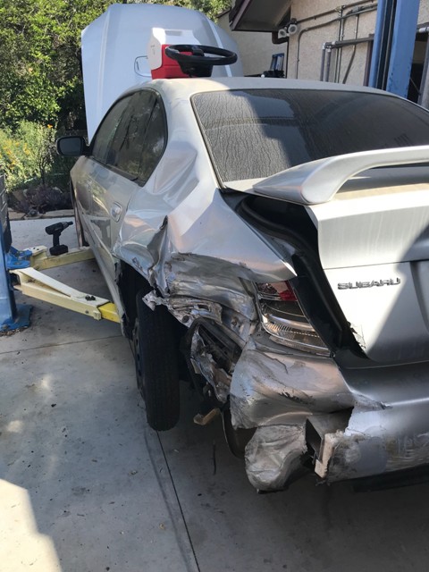
I spent the weekend tearing it apart, and putting away the parts I will need to swap this EJ255 engine into my 914. I plan to adapt the gauge cluster (replacing the 1998 Forester cluster I'm currently using) into a new dash pod, the drive-by-wire accelerator pedal, and I'll see if I can adapt the tilt-steering column and related factory parts (leather Momo wheel, headlight/turn signal stalk, cruise control, etc.). Obviously, the airbag won't be functional. I kept a portion of the Legacy's dash top to help mock up the dash pod, and I pulled the entire wiring harness (except for the wires behind the b-pillars). What a PITA!
I plan to adapt my current air-to-water intercooler setup, flywheel/clutch, Accusump, cast aluminum oil pan, and the exhaust from my current EJ22t engine. I'll keep the EJ255's rear inlet orientation so that I can run an A/C compressor (more on that later) and alternator in the factory EJ255 locations; I'll toss the power steering pump. If you'll remember from a previous post, I had to flip the intake on the EJ22t to avoid cutting into the rear trunk/engine firewall -- but the EJ255's intake is much more compact. Below are a couple of pics.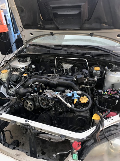
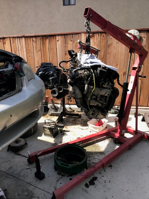
I then paid $150 to have it hauled away yesterday, although I filled it with all the car-related junk I've collected over the past six years from my various other engine swap projects (BMW S52 into 318ti, VW tdi into Eurovan, etc.) and other car rebuilds -- so it was money well-spent. I resisted the urge to salvage every last part from the Legacy GT that I could possibly sell on eBay or Craigslist -- that is becoming such a PITA lately that I just took what I needed, or that could be quickly/easily sold (5EAT transaxle, rear differential, climate control/radio pod, battery, one unbroken headlight). I also grabbed the under-wing 3rd brake light to see if it can be adapted to my 914.
Over the next couple of months, my plan is to replace all gaskets, seals and hoses on the engine while I continue to hammer the car at autocrosses and possible Buttonwillow track days to see what else can break. I'll also dig into the wiring harness; this time I plan to mount the ECU in the cabin rather than the rear trunk. Then I'll prep it for paint, test fit the new EJ255 engine, pull everything off the chassis and paint it. Stay tuned!
Posted by: JRust May 22 2018, 11:39 AM
Nice score bud. That is the way to do it. Make for a nice little upgrade later for sure. Should have some more bottom end grunt as well
Posted by: strawman May 22 2018, 12:38 PM
I just got off the phone with Travis at Dutchman Axles, and my new axle shafts will be here by the middle of next week. I'll share the drawings once they're emailed to me.
One more picture: these are the wheel centers from my BBS Motorsports E52 wheels. Central Coast Powdercoating is charging me $200 to blast these and coat in Gloss Black. Replacement hardware is coming (from McMaster-Carr), so my hope is to re-polish the lips/barrels, assemble the wheels and have 'em back together before the next autocross on June 16.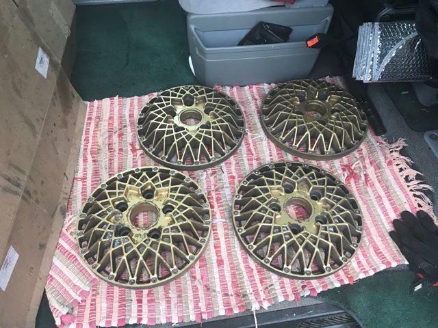
Posted by: charliew May 22 2018, 03:21 PM
That's my plan so far even though I eventually want to build a Subaru manual trans with the final drive modified to 3:55 or so. That ratio is also why I've modified an SVX trans for 2wd behind my EG33 - it came with the donor car and it works. It's REALLY heavy though - probably 200+ lbs so my rear springs will be upgraded as well. I'm interested to see how well the automatic will work with highway cruising. Can you say 80mph at 2600rpm?? And the drivetrain shock should be less as well - I'm using the hybrid axles from Dutchman so we'll see...
that will probably work pretty good unless you hit a pothole or speedbump under power, not sure about that but I bet it will be just fine. can you do the obx in the svx tranny?
Posted by: strawman May 22 2018, 03:26 PM
One more for today: here is the engineering drawing I just received from Dutchman Axles. FYI, I am using 108mm 911 CV joints on the big end, and Subaru inner tripod joints on the small end. The cost is $585 for the pair.
Dutchman_engineering_drawing_of_914_axles.pdf ( 43.65k )
Number of downloads: 113
Posted by: charliew May 22 2018, 03:32 PM
my son's 05 sti used a pulse width modulated fuel pump with a little driver box if I remember correctly to change the pressure. I actually thought the legacy hotrod version used the 6 spd though. When I redid my son's empi type wheels on his bug I used a 320 grit flapper wheel and then a scotchbrite roll and they might have looked better than new. One of them was pretty gouged up on a lip from getting upside down. The lip was just not quite as thick anymore. I like the bbs wheels. my fieros have the gm copys but one piece of course.
Posted by: strawman May 22 2018, 03:37 PM
Still waiting for someone to do a Subaru motor and auto gearbox in a teener! Can they be abused a little without blowing up?
This would be cool. The biggest problem may be the electronics -- both the 4EAT and the five-speed 5EAT have a separate Transmission Control Unit that likely needs to communicate with the ECU. There is at least one http://www.importperformancetrans.com/subaru5eat.shtml that builds 5EATs and related equipment to take abuse in the relatively heavy and higher-boosted Legacy GT/XT and Forester XT.
If I cannot sell the 5EAT that came out of my car in the next few weeks, I'll open it up (in the name of science, of course!) and see if it is possible to lock the FWD and RWD together. I'll also check to see what sensors are in each end.
Posted by: Chris H. May 22 2018, 04:12 PM
In a stock Subaru with a 4EAT there is a fuse you can pull that puts the trans in front wheel drive mode.
Posted by: effutuo101 May 22 2018, 07:42 PM
Depends on how you do the tilt steering. Jeff had to do a bunch of fab work on mine. All of the geometry changed. It may be easier to put a removable steering wheel on the stock steering unit.
Nice score! Watching this thread.
Posted by: mgp4591 May 22 2018, 08:17 PM
In a stock Subaru with a 4EAT there is a fuse you can pull that puts the trans in front wheel drive mode.
There is Chris but all it does is disable the electric clutch that engages the driveshaft to the rear. It still doesn't get rid of the long tailshaft needed to couple the rear shaft so that's why I picked up the 2wd endplate and shaft/bearing assembly - drops right in.
Posted by: 76-914 May 23 2018, 08:00 AM
Still waiting for someone to do a Subaru motor and auto gearbox in a teener! Can they be abused a little without blowing up?
This would be cool. The biggest problem may be the electronics -- both the 4EAT and the five-speed 5EAT have a separate Transmission Control Unit that likely needs to communicate with the ECU. There is at least one http://www.importperformancetrans.com/subaru5eat.shtml that builds 5EATs and related equipment to take abuse in the relatively heavy and higher-boosted Legacy GT/XT and Forester XT.
If I cannot sell the 5EAT that came out of my car in the next few weeks, I'll open it up (in the name of science, of course!) and see if it is possible to lock the FWD and RWD together. I'll also check to see what sensors are in each end.
Jeff, I believe I have a 5 EAT controller. If you need one PM me and I'll dig around for it. Kent
Posted by: mgp4591 May 23 2018, 11:09 PM
If I cannot sell the 5EAT that came out of my car in the next few weeks, I'll open it up (in the name of science, of course!) and see if it is possible to lock the FWD and RWD together. I'll also check to see what sensors are in each end.
[/quote]
Pull the tailshaft off the 5EAT and you'll see the electromagnetic clutch assy. You should be able to take the endplate and shaft assy from a 2wd and drop it right in - there's no way to lock up the automatic like there is the manual that I'm aware of. Check out the size of the electric clutch assy and necessary tailshaft...
[attachmentid=651966] 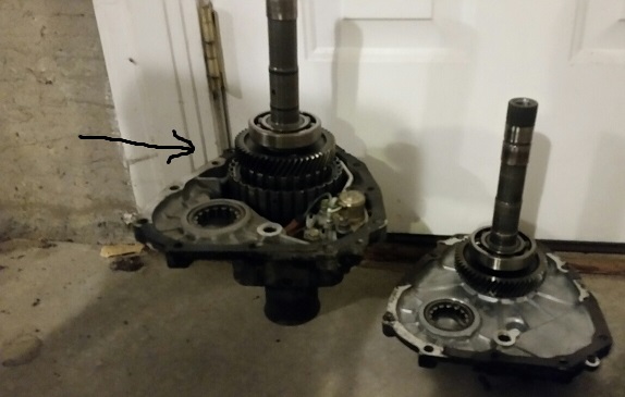
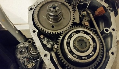
Posted by: Andyrew May 24 2018, 09:37 AM
Depends on how you do the tilt steering. Jeff had to do a bunch of fab work on mine. All of the geometry changed. It may be easier to put a removable steering wheel on the stock steering unit.
Nice score! Watching this thread.
Fabbing up the tilt steering on mine caused a bunch of problems. Just FYI. I wouldnt do it again.
Posted by: strawman Jun 1 2018, 10:49 AM
Fabbing up the tilt steering on mine caused a bunch of problems. Just FYI. I wouldnt do it again.
Yeah, I'm starting to rethink this. Since it only lowers the column about an inch -- and it doesn't telescope -- it probably is not worth the headaches. To override the factory immobilizer, I'll have to place the chipped key and ignition "antenna" under the dash.
Below is a picture of one of the pair of gleaming new Dutchman axles shafts, sitting next to the mock-up. You can see that they tapered it down from the Porsche 911 outer CV spline to the smaller Subaru inner tripod joint spline. All told, with shipping of my parts to Dutchman, the cost of the axles and shipping back to me, it cost just under $700. The Hy-Tuf material is some sort of space-age, high-strength and low-alloy steel used for aircraft landing gear. So the axles are likely not the weak-point anymore. I hope to get the car back on the road this weekend. I also need to assemble my BBS Motorsports wheels now that I've got the centers back from Central Coast Powdercoating. More pics to follow soon!
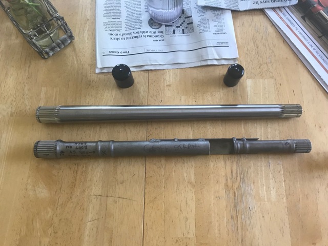
Posted by: charliew Jun 1 2018, 01:14 PM
those axles look real nice. I don't dee how anything will break now. A long time ago I corresponded with a well known tranny guy that was on nasioc a lot, and he thought the light weight of the 914 and the smaller tire footprint would sorta protect the 5spd 05 up manual tranny in this application. course if a person really tries to tear something up in a car he can usually manage that feat.
Posted by: strawman Jul 22 2018, 09:36 PM
Man, life gets in the way. Finally got the axles together, the tires mounted on the resto-ed wheels, and everything buttoned up today. It was great driving it again. have an autocross on Saturday; I am hoping everything goes well and I don’t break anything. In the meantime, I’ve been prepping the EJ255 engine for installation after the autocross season ends in early fall.
Posted by: strawman Nov 12 2018, 02:35 PM
The Subaru EJ22T engine and accessories are now officially for sale as I wind down the preparation to install the "monster" EJ255 engine. You can find it in the Classifieds.
Posted by: strawman Nov 30 2018, 01:02 PM
A quick update: I helped load the Suby EJ22T engine into Phillip's truck last Sunday, and I continue to ready my car for the swap to an EJ255 that I took out of the '05 Legacy GT (LGT) mentioned above. I look forward to helping him with his swap, since he lives in nearby Paso Robles.
Below are some of the things I'm doing in prep for my swap:
1. E85 fuel for increased octane and a cooler intake charge -- in order to run ethanol, I needed to upgrade the fueling system. I've recently purchased Injector Dynamics 1050X (1000cc) top-feed injectors, Cosworth aluminum fuel rails, -6AN fuel lines and fittings run in a parallel setup (rather than series), an Aeromotive 13129 adjustable fuel pressure regulator, Radium 10-micron stainless media fuel filter, electronic fuel pressure sensor, AEM 340 lph fuel pump, and a Cobb 312550 Flex-Fuel kit. I also deleted the stock Tumble Generator Valves & sensors from a set of 2008 WRX top-feed intakes, welded up the holes using my TIG, and then smoothed and port-matched them to the heads. I already installed Tangerine Racing stainless 9.5mm feed and 8mm return fuel lines, but need to wire-in/install the Suby fuel pump controller somewhere near the fuel tank/pump.
2. Rebuilt heads -- on Sunday night I checked the valve lash clearance. Dammit; one of the exhaust valves on cylinder #1 has a tight clearance. I couldn't even get an 0.003" feeler in, when an 0.0138" is ideal. Bigger dammit: I then ran a leak down test and found the #1 cylinder is fine, but one exhaust valve each on cylinders #3 and #4 are leaking badly. I will remove the heads this weekend and send them to OutFront Motorsports in Buena Park, CA for rebuilds. Base cost is $550 for the pair. I'm also having the AVCS cam gears rebuilt while they're out; the AVCS varies the timing of the intake cams for better low-end grunt / high rpm power based on load and rpm. I plan to use ARP 11mm studs and OEM head gaskets when I put it all back together.
3. Turbo & oiling system -- I recently purchased a new/custom BNR hybrid VF40/18G turbo that uses a TD05H turbine. It is good to about 365whp in an AWD Subaru Legacy GT, which translates to about 425hp at the crank. As part of this setup, I also upgraded the oiling system (11mm oil pump vs. 10mm), and purchased improved supply lines & separate filter for the turbo. This meant I also had to upgrade my VDO oil pressure gauge/sender from 0-80 psi to 0-100 psi. I will adapt the 3-qt. Accusump system I had on the EJ22T, as well as the SmallCar cast aluminum oil pan. My VDO oil temp sender is mounted in the oil pan drain plug. I will also install a Grimmspeed 3-port Electronic Boost Solenoid in place of the OEM unit.
4. Exhaust -- I will start out using the shortened Invidia bellmouth downpipe and Flowmaster 843015 muffler that I made for the EJ22T swap, even though it is a little (lot!) loud. I bought a used Grimmspeed catless uppipe to help quicken spool-up. I will port-match the EJ255 cast iron manifolds, and drill/tap a hole to install the VDO EGT probe. The EJ255's ECU only needs one O2 sensor in one of the two iron manifolds (after I tune-out the post-cat one), and I'll keep my AEM wideband O2 air-fuel ratio sensor in my downpipe (and plug the hole that the EJ22T O2 sensor used).
5. Intake system -- I originally planned to to use the FrozenBoost Type 13 (11"x9.25"x3.5" with 2.5" inlet/outlet) air-to-water intercooler from my old EJ22T, but since it is only good to about 350hp I decided to upgrade to the larger http://www.frozenboost.com/air_water-ic/water-to-air-intercoolers-p-214.html unit (12.25"x12.25"x4.5" with 3" inlet/outlet) good for up to 600hp. This of course required new/larger hoses, piping, clamps, etc. I will install a Tial blow-off valve that vents to atmosphere, since I'll also be switching from the stock MAF to a speed density system, which does not require a Bypass Valve (BPV) recirculating system. I also purchased an IAG Street Series Air-Oil Separator (AOS) system to remove vapors from the crankcase, which is especially important when using E85 fuel. The IAG AOS system is expensive, but it apparently does the best job of keeping oil out of the intake tract. My turbo inlet is custom; I'm using an HPS offset silicon connector at the turbo, which allows me to use a 3" aluminum tube (with ports only for the PCV/AOS system; no BPV port necessary) straight to a huge K&N cone filter. This is possible because it is a straight shot forward from the turbo now that I've removed the factory power steering pump.
6. ECU & Tuning -- I purchased a Cobb AccessPort V3 to both monitor the tune in real-time and so that my tuner (Pokrajac Auto in San Luis Obispo) change pro-tune it. Mike Pokrajac is a well-known Suby and Mitsubishi Evo tuner on the Central Coast, and he just installed a Mustang Dyno that should be up-n-running in the next week or so. My ECU is out of a '04 Subaru Forester XT, which will be flashed to mimic an '04 WRX STi to start the car prior to tuning; I modified my '05 LGT engine wiring harness to match that of an '04 STi, too. The system will automatically sense the percentage of ethanol content and adjust all pertinent tuning parameters; it allows me to also run gasoline without having to manually switch tunes. I am shooting for a conservative 300whp on E85, which Mike assures me is safe/conservative and won't require me to upgrade to forged pistons (but I'll start saving money now, anyway ).
7. Wiring -- instead of mounting the ECU in my rear trunk, I will mount the '04 FXT ECU inside the cab between the seats. I will also install a couple of Summit fuse panels in that area, which I plan to cover with a custom fiberglass console. That will also hide my shifter cables/console. I'm toying with using the '05 LGT gauge cluster, since I have to modify my original fiberglass housing I made for my '98 Forester cluster that I'm currently using.
My first 2019 PCA autocross is in early February, so I've got my work cut out for me. I'll post some pics of the heads this weekend after I pull 'em off. Stay tuned!
Posted by: strawman Dec 13 2018, 01:19 PM
Well, I forgot to take pics of the heads before packing them and shipping them off to OutFront. But here they are all rebuilt-n-shiny as received back yesterday. OutFront shaved the heads two-thousandths to ensure they are perfectly flat, ground the valves/seats, installed new valve guides (extra $$), set the valve lash, and leak-tested them. With shipping and tax, I paid $823 not counting the $46 to ship 'em to OutFront last week.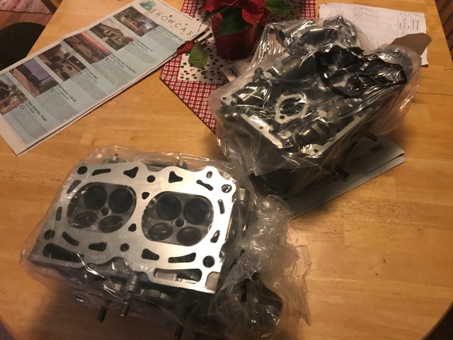
This weekend I'll chase the threads in the block, install the new ARP head studs, place the OEM head gaskets, and torque these heads on. That will make my wife happy, since she doesn't quite appreciate "art" on the kitchen table like I do...
On other fronts, it turns out the SmallCar cast aluminum oil pan interferes with the stock "oil cooler" that is sandwiched between the block and the oil filter. Actually, after some research I found that this is a misnomer, because it is actually an oil warmer to quicken the clean-emissions warm-up time. So I removed it; the factory eliminated it in MY2007, too. To eliminate it, I purchased a factory plug to block-off the coolant passage in the block (P/N 11021AA121), bought a shorter threaded pipe to mount the oil filter directly to the block (P/N 15018AA050), and muscled the coolant pipe out of the water pump and tapped it for a 1/4" NPT stainless plug. That'll save about three pounds and also eliminated three small molded rubber hoses.
The bummer is that I stripped the M6-1.0 threads in the block for one of the oil-pan bolts... so I'll pick up a Heli-Coil kit today and fix it tonight. Thank gawd the engine is still on the stand!
I also purchased all of the fuel hose and -6AN connections ($$$), as well as a mount for the Radium fuel filter. I'll mock up the fuel system this weekend and snap a few pics. Stay tuned!
Posted by: strawman Dec 20 2018, 12:51 PM
Last weekend I finished up the fueling system, and dropped off my custom-made filter & E85 firewall mounts at the powdercoater on Monday. Once I get those back, I will mount everything up and show how it ties into my Tangerine Racing stainless fuel lines. I also carved out some time last night to assemble the long-block, after needing to buy some more small parts (gaskets, spacers, etc.) before mounting the heads. I also had to pick up my rebuilt Active Valve Control System (AVCS) cam gears from Pokrajac Motorsports. Below are some pictures.
Here is the right side of the short-block; you can see the ARP studs and OEM head gasket, as well as the side of the SmallCar cast aluminum oil pan.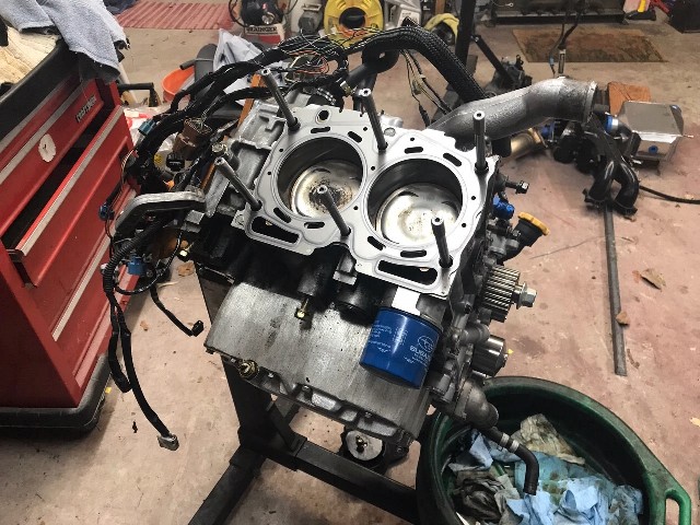
Next up is the right side head with the cams/caps removed, the ARP hardened washers installed, and ready to be torqued onto the block. ARP calls for three stages: 30 ft/lbs, followed by 60 and then 90.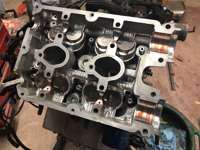
Here are the cams and caps bolted on. The intake (upper) cam uses a hydraulically controlled solenoid to advance the timing under higher load/rpm situations. Subaru's AVCS system is somewhat similar to VANOS (BMW) or VTEC (Honda). I used Permatex Ultra Gray for the forward caps for both pressurizing and leak prevention.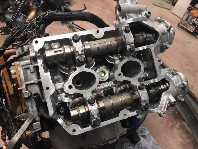
The pics below show the valve cover mounted, the final long-block assembly, and then the cam gears -- including the AVCS intake gear -- on the left side. Before I called it quits last night, I mounted the right side cam gears, TGV-deleted intakes, AVCS solenoids. oil feeder lines, cam sensors, and a few other items. I hope to find time tonight to install the OEM timing belt and covers, and to wrap up the engine wiring harness, exhaust/turbo mounting/etc. 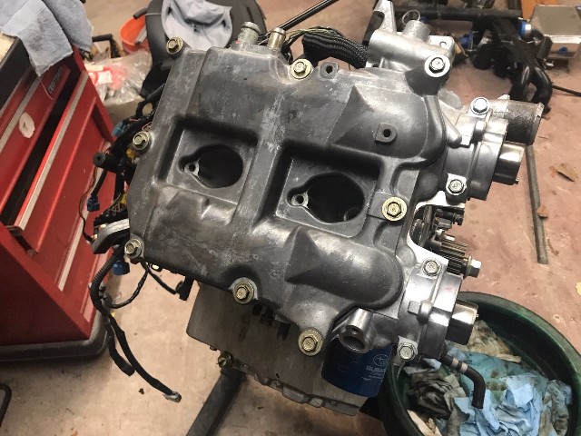
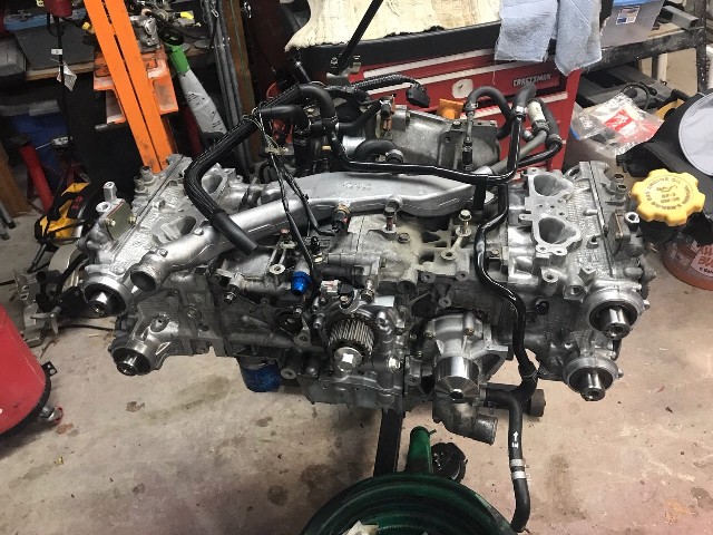
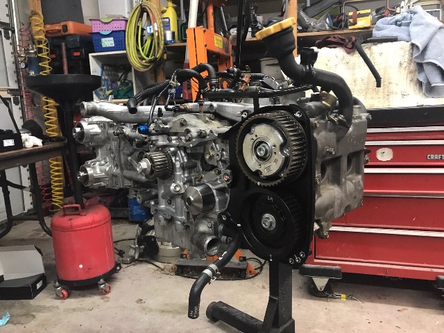
I still need to weld up the final intercooler piping, the Tial blow-off valve and bungs for speed-density/air-intake sensor, which I will tackle after visiting my folks in my hometown of San Francisco for the holidays. Happy Holidays to you all!
Posted by: 76-914 Dec 20 2018, 02:18 PM
How much HP do you expect to gain with this set up vs. the old engine? Did you spring for Outfront's reinforcement kit fr the open deck? I've read those studs are the ticket!
Posted by: Chi-town Dec 20 2018, 02:36 PM
stock EJ255, stock heads and cams, modded VF40, AWIC on E85 should be in the 330-360whp range.
I would consider having the block bored and honed with a forged piston set to avoid issues long term. Broken ring lands are no fun.
Posted by: effutuo101 Dec 20 2018, 08:12 PM
I dyno at over 300 torque (2800rpm) and 280 hp with my small G20. Cant wait to get the car on the road and finish break in. Next up is a different spool to move the curve up a bit.
Same 2.5 16v motor.
Posted by: strawman Dec 24 2018, 10:40 AM
Based on the mods I’d done to the previous engine, I believe it made 200 whp. I will “detune” this current engine to be about 300 whp so that I don’t stress it too much using the stock pistons. If (when?!) I blow it, I’ll go with a Stage 2 closed deck short block and turn up the wick a bit. Honestly, it starts to get a little silly with too much horsepower and limited tire size even with flares. I could easily spin 200 treadwear tires in second gear with the old engine...
Posted by: strawman Dec 31 2018, 05:37 PM
No matter how many times you measure, you never really know if everything is going to fit until you mock it up. In other words, all good planning is rewarded with setbacks...
Below is a picture of the long-block and transaxle mated up on my engine cradle, including the newly-powdercoated engine mount "U-bar" and trans mount. I started by using my cherry-picker to lift the engine from the engine stand to the cradle, and then using it to help mock the transaxle up to the engine (no flywheel yet).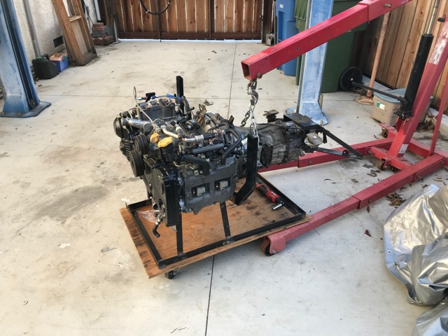
The next pic is of the car getting ready to gobble it up.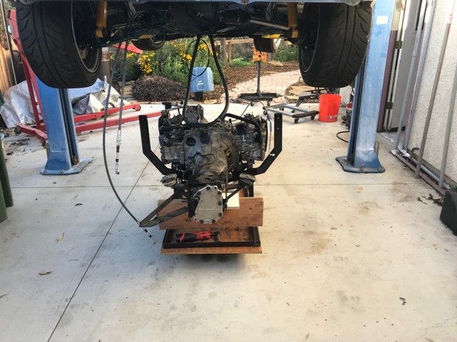
I ended up having to remove the U-bar so that I wouldn't scratch it up on the rear trailing arms during the car lowering process; I used yellow painter's tape that you can see in the pic below to protect everything. With the help of my lovely wife, we fished/guided the U-bar in place after roughing up the location of the engine in the chassis. It took me about 90 minutes from the time I cherry-picked the engine from the engine stand until the engine/trans were fully mounted in the chassis.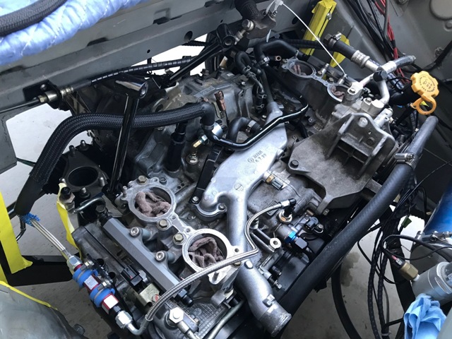
Now you can see where I ran out of space (talent?)...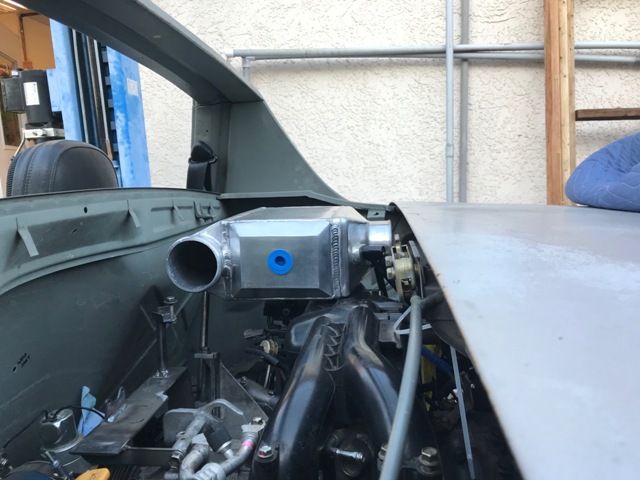
The intercooler inlet (passenger side of engine bay pointing to the rear of the car) could technically work by massaging the engine/trunk firewall and clearancing the engine lid cross-brace. However, the problem is the throttle body's orientation -- it aims at an upward-and-to-the-right angle directly at the bracing for the engine lid latching system. Three solutions are possible: 1) move the engine lid latch mechanism and bracing, and build "boxes" for the clearance needed on the engine bay/trunk firewall; 2) flip the plastic intake manifold 180 degrees; or 3) move the intercooler to the trunk. Option 1 would result in maximizing trunk space, and I already have all of the silicone couplers and aluminum tubing. But is requires a lot of fabrication and would still be VERY tight. Option 2 will require new alternator and air conditioning compressor mounts in order to also maximize trunk space, but will require a lot of new tubing work, rewiring, etc. Option 3 also requires new tubing, since it will open up the engine bay and ensure the shortest intercooler tube routing. But it further reduces trunk space.
I've opted for number 3. Since my engine tuner recommends that, instead of using 3" intercooler tubing throughout, I use 2" tubing and step it up for the 3" OD intercooler in- and outlets. The smaller tubing size also apparently helps maintain charge-air speed within the intake system while also requiring less physical space. I've already ordered all of the necessary tubing, silicone couplers, clamps and other assorted items. Hopefully, everything arrives in time to dive in next weekend.
In the meantime, I'll wrap up the fueling system, ECU mounting, wiring and reworking of the AWIC hose routing. Stay tuned!
Posted by: Tdskip Jan 1 2019, 07:52 AM
Based on the mods I’d done to the previous engine, I believe it made 200 whp. I will “detune” this current engine to be about 300 whp so that I don’t stress it too much using the stock pistons. If (when?!) I blow it, I’ll go with a Stage 2 closed deck short block and turn up the wick a bit. Honestly, it starts to get a little silly with too much horsepower and limited tire size even with flares. I could easily spin 200 treadwear tires in second gear with the old engine...
That is a lot of power!
Posted by: charliew Jan 1 2019, 12:35 PM
I know you have done a lot of research on these mods but I thought about the oil restrictor in the head for the factory turbo. I have read in the far past about too much oil in the turbo getting into the air path. Do you have or need a restrictor in this new setup? e85 is a lot of work and expense, I know it is for the future though especially all out performance on the track. I probably missed a part about maybe a dual disk clutch and lighter flywheel? or just new factory parts?
Posted by: 914forme Jan 1 2019, 01:01 PM
Oil in the pathway does happen, I have used the Mann Provent 200s in all my turbo diesels and Scott's PORSTI build used one, they do pretty much eliminate the issue of oil in the intake. And they let all the "bad stuff" pass as intended.
Scott's prevent drains down into the dips stick tube. I have one on my ML320 right now, and I just have a valve, I drain it once a week, and I am collecting al the drainage to see how much oil I have recovered between oil changes. If I get into quarts I will drain it back to the engine, if not, I will leave it as is. My drain hose is about 2 get long, with a ball valve mounted low.
Also your solution to your intercooler is is an air to water unit, packaging is smaller, can be mounted out of the way with no airflow requirements.
Posted by: strawman Jan 2 2019, 11:40 AM
I spent a (admittedly) hazy New Year's Day working on my teener; I was overserved the night before with friends at an English Beat concert. 
The more I looked at the idea of the intercooler (I/C) in the the trunk, the less I liked it. My main concern was the extremely short turbo outlet to I/C tract -- such a rigid connection will eventually damage the turbo with engine movement. I came up with a new I/C mounting system that will keep it mounted to the engine within the engine bay; those parts are on order and should be here early next week. I've essentially moved the I/C toward the passenger side and lowered it, while the tubing to the throttle body wraps around (rather than over) the plastic intake manifold on the driver side. I'll have to redo the I/C coolant pump-n-plumbing, but that is relatively easy. However, with all of these starts-n-stops on the I/C mounting design, there's gonna be a big pile of new & unused parts.
I also fabricated a mounting system for my IAG Performance air-oil separator (AOS) http://www.914world.com/bbs2/index.php?showtopic=83031. The IAG AOS is highly regarded in the Subaru world, although it is over $400 after taxes and shipping. Many race setups vent crankcase vapors to atmosphere, but when using ethanol, IAG recommends their "street" setup that uses the engine's vacuum to help evacuate corrosive ethanol fumes from the crankcase. It is a beautiful piece of machinery, although it looks like a spider with all the hoses coming out of it -- and that makes packaging in the 914 engine bay even more challenging. It uses engine coolant to heat the AOS chamber, which helps vaporize the moisture and "scrub" the air that goes into the intake tract (pre-turbo); the gathered oil is drained back into the crankcase. I'm happy with the mocked-up mount I devised (about four hours' worth of work) yesterday; I'll snap some photos when it is all set up.
Charlie, I'm running a separate/mini oil filter with the correct-sized restrictor from the block to the turbo. Suby engines are apparently pretty rough on turbo oiling, so I didn't want to risk early failure. In fact, BNR Performance will only warranty their turbo if you abide by their oiling requirements. I'm running a lightened flywheel with a Stage II sprung clutch. It held up well with my previous EJ22T with hard launches and other general abuse.
I made the mistake of powdercoating my engine U-bar mount, and my new Grimmspeed uppipe to the turbo rubs against it. I'll need to notch out a bigger channel than the one that worked for my old EJ22T's uppipe, and weld-in a larger reinforcement. Then I'll get it blasted and powdercoated again. It was "pretty" for a while...
Posted by: strawman Jan 11 2019, 11:14 AM
I removed the engine/trans last weekend, and devised the new air-water intercooler (AWIC) mounting system. First up is a picture of the old AWIC setup, which as described in earlier posts sat too high and too far back. As you can see, I used 3" tubing and the charged-air pathways were very short/direct. You can also see that I powdercoated the mounts, which are now beautiful and time-sucking paperweights. 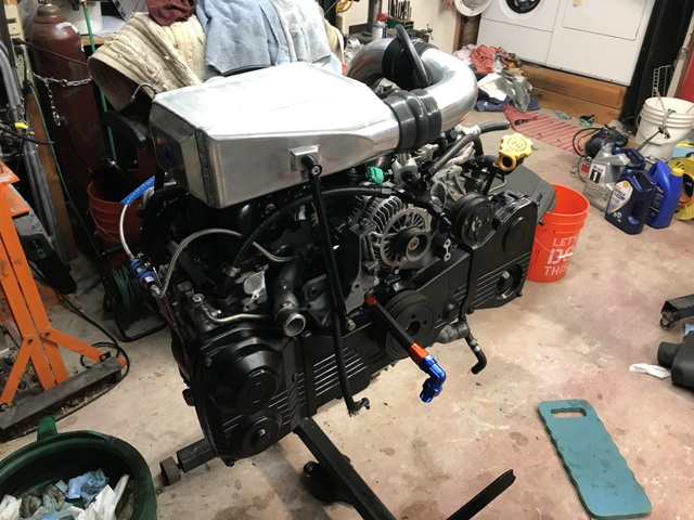
The new mounting setup moves the AWIC lower and forward, as shown below. The charged-air pathways are slightly longer than the old setup, but the smaller 2" diameter tubing will apparently help with maintaining airspeed and throttle response. I'm using 1/2" OD steel tubing for the three AWIC mounts because of its strength and relative lightness, as well as a few cool http://www.bungking.com/counterbored/ that allow use of stainless allen-head bolts. It takes extra time to fish-mouth each joint, but it is strong and cool-looking. You can see the yellow tape-protected piece of 2" intercooler tubing that comes from the drive-by-wire throttle body and wraps around/over the plastic intake manifold; I'm waiting on delivery of a 30 degree mandrel bend tube that I'll weld in to connect it to the black silicone coupler on the AWIC. You can also see my fuel feed/inlet mounting (the black y-shaped fitting on the "pedestal") and the Aeromotive adjustable fuel pressure regulator (FPR), which is the outlet back to the tank. That portion of the mount also provides protection from a failed alternator or A/C compressor belt. That is particularly important for the -10AN Accusump feed line that goes into the front of the block (you can barely make-out the black 45 degree fitting), as well as the fuel lines. I'm running 3/8" feed and 5/16" return for the fuel lines, which my tuner says is the bare minimum for my horsepower goals. The doohickey on top of the FPR is an electronic pressure sensor, which feeds info to the COBB AccessPort and will pull timing / reduce boost if the fuel pressure drops below a preset threshold... this helps prevent lean-running under load and can save the engine.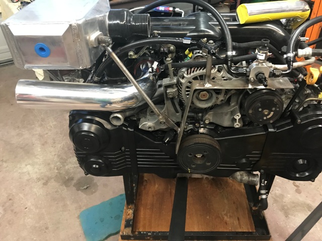
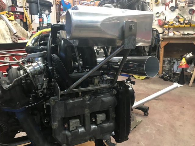
From the side view above, you can see the relatively elaborate "cage" I fabricated for the outer mount. I will add a mount for the engine wiring harness plug to this cage once I finalize the wiring this weekend. You can also see the 90 degree tube that will connect a large K&N cone air filter to the turbo inlet. I still need to weld on some mounting tabs to this big tube, as well as a couple nipples for the Air-Oil Separator system hoses.
What's next? I need to weld a small bung onto the charged-air pipe for the speed density sensor and a large one for the Tial blow-off valve. I hope Brown Santa comes today to deliver materials for the custom flange I'll fabricate to mount on the turbo outlet, which will connect to the inlet side of the AWIC.
Posted by: 76-914 Jan 11 2019, 04:56 PM
So close to driving it. Cool stuff.
Posted by: strawman Feb 8 2019, 11:51 AM
Spent many an evening, weekends and vacation days (and strains on my marriage!) to get the car ready for an autocross this weekend. But at 8:30 last Sunday, I finally threw in the towel. The next race is March 2nd, so I have a new deadline...
Here are some pictures of my progress. First up are some firewall pics showing my Cobb FlexFuel (E85) fueling setup & fuel filter, then the hole for the wiring harness, and then my grommet solution for the shifter cables. The grommet for the shifter cables came out of a late-80s Toyota pickup -- essentially a blank rubber plug and a metal mounting "frame". I put the rubber plug in the freezer overnight to harden it, and then drilled it at the appropriate angle for both cables.
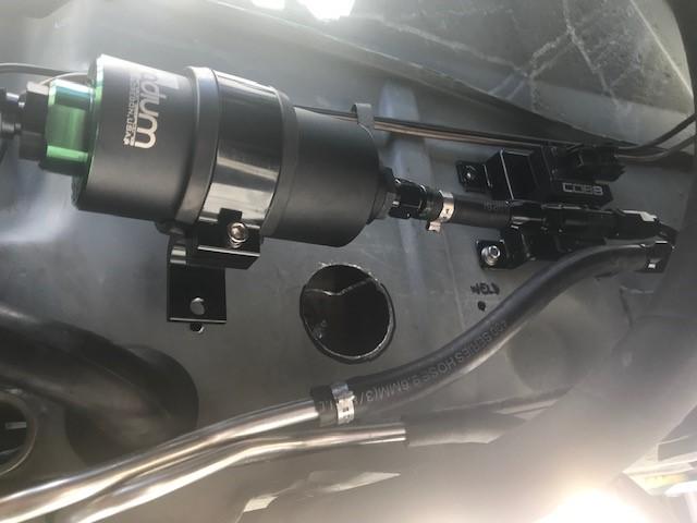
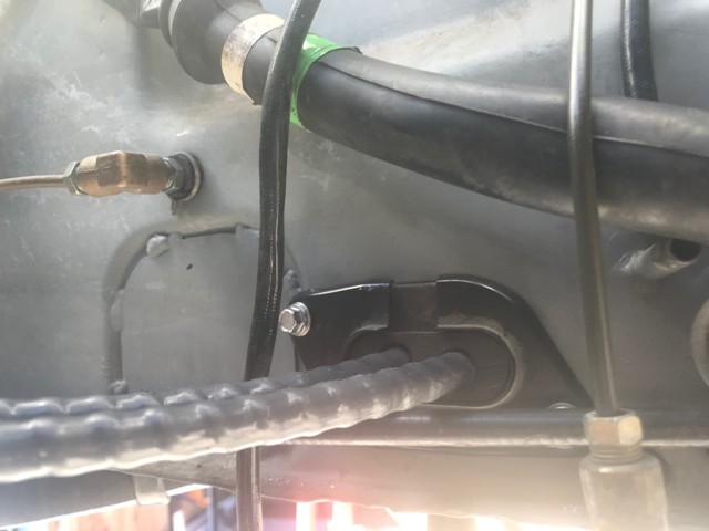
Next up are some pics of my accelerator solution. The EJ255 uses a drive-by-wire throttle, which is essentially just a big potentiometer. Some guys have mounted the stripped-down potentiometer in the engine bay and actuate it with the throttle cable. But since I'm mounting the ECU in the cabin, the factory wires and grounding shields would reach. Below show where I welded in the mounts for the pedal assembly. I also had to heat up and bend the pedal arm to make it fit. I am happy with the placement, and -- at least in my garage -- it will allow good heel-toe action.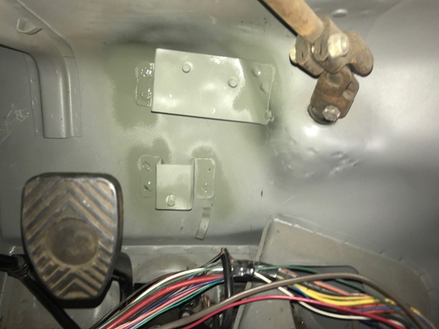
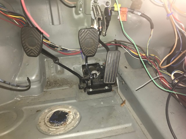
The next pictures show the engine wiring harness mounted on the engine without the turbo, intercooler or piping. You can see the firewall grommet sitting on the table -- it is from a 1991 Lexus LS300. I spent a couple hours in a Pick-n-Pull violently tearing out grommets, and this one seemed the best option; it has a metal mounting frame, has a snorkel on both sides, and the mid-section is long enough to span the firewall cavity. It was only $5, but it required a lot of swearing, wire slicing and cuts to my hands. I ended up slicing the grommet lengthwise to go over my wire bundle and used 3M 4799 Industrial Black Rubber Adhesive (elephant snot). I tested this goo on a spare grommet and let it set overnight. I tried to pull it apart but literally tore the rubber next to it. One trick I learned is to use narrow gauge SS wire in each pleat to line up the rubber while it cured. I'm really happy with the results but didn't take any pictures. 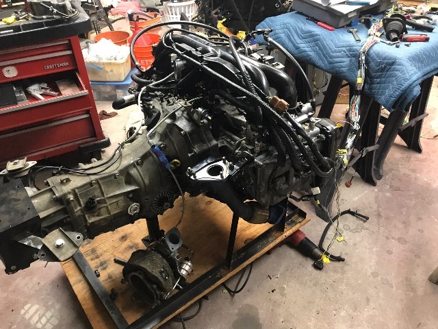
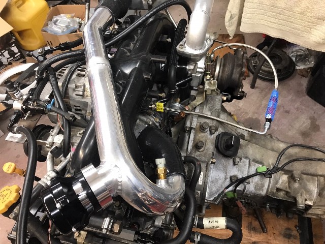
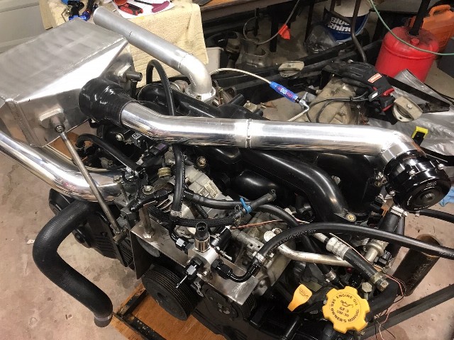
You can see the Intake Air Temp sensor on the intake piping near the throttle body; it is from a GM car. This sensor will be used for my speed-density setup, which allows me to delete the factory Suby Mass Air Flow sensor. You can also see the Tial blow-off valve, which is right behind my ear. Yes, it will probably be too (boy racer) loud but I couldn't find another suitable place to mount it. The turbo outlet pipe is also in a raw form; I hadn't yet cut it and beaded the end for the silicone elbow into the intercooler. More on that later...
Below is a final picture of the engine in the car, followed by an early stage of bringing the wiring into the cabin. I ended up making a metal frame for the grommet and screwing it into the firewall (cavity). A word of advice -- avoid the shitty SS screws from Home Depot! Two stripped (I should have stopped at that point!), and the third broke off in the hole. I was able to fight out the broken piece, and bought quality screws at Ace Hardware when it opened the next morning.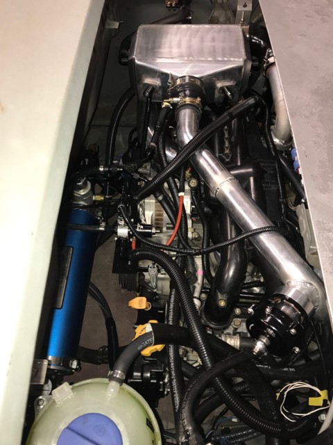
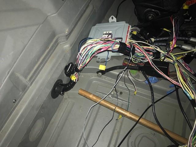
The 90 degree silicone elbow from the 2" turbo outlet tube to the 3" inlet of the intercooler is only 1/8" from the hole for the targa roof cup hole. So I plan to cut off the 3" inlet, weld on a plate, and weld a tight 2" cast aluminum elbow to provide more room. The intercooler piping also interfered with the engine lid latch cable tube -- so I cut out the mount for the cable tube and pushed it back out of the way. I'll need to devise a new system, but will at first just run without the engine lid.
This weekend I will finish up the wiring, flash the new ECU code and turn the key. Wish me luck!
Posted by: 76-914 Feb 9 2019, 10:08 AM
Posted by: rhodyguy Feb 9 2019, 10:52 AM
Very cool. Did you do valve guide work on the heads? That 4799 might be the hot ticket for splitting and replacing the wire bundle snorkel in the engine compartment.
Posted by: strawman Feb 11 2019, 12:03 PM
Again, I failed to finish the wiring this weekend. I am a local PCA autocross instructor, so I spent all day Saturday for the clinic at the Santa Maria Airport. That only left me a few hours on Sunday. I finished wiring in the Fuel Temp Sensor, Fuel pump relay bypass (actually, the factory relay triggers a larger-capacity one in the frunk, which allows larger-gauge wire to run the pump through a rewired Fuel Pump Controller), wired the AWIC pump, and bent up a mount for a combo fuse panel and factory relays at the ECU inside the cabin. The plan now is to finish up the wiring and revised turbo-to-AWIC piping this week, and hopefully start it next weekend.
Posted by: strawman Feb 11 2019, 12:05 PM
Did you do valve guide work on the heads?
Yes, I had Outfront Motorsports completely rebuild the heads to stock specs. They look beautiful and the valve clearances were spot-on.
Posted by: strawman Mar 14 2019, 08:09 PM
First start today after a lot of struggles with wiring and tune. My tuner has been VERY patient with me through all of these struggles. Good news is that I’ve got good oil pressure and no untoward noises. Here is the video:
https://youtu.be/4PleftVjvu0
Posted by: 76-914 Mar 15 2019, 09:17 AM
Mind sharing the re-flash of the ECU?
Posted by: effutuo101 Mar 15 2019, 06:02 PM
Oil! Well done!
Posted by: Andyrew Mar 16 2019, 08:49 AM
Sounds great!! Fantastic progress!!
Posted by: strawman Mar 17 2019, 12:24 PM
Mind sharing the re-flash of the ECU?
Not sure my final tune would do you any good unless you had the exact same setup as mine. My tune is based on stock EJ255 internals, cams and slightly ported stock exhaust manifolds, but with the followings aftermarket mods: Grimmspeed catless uppipe, shortened Invidia bellmouth downpipe and Flowmaster Delta 10 3” inlet/outlet muffler, BNR 18g-based hybrid turbo, Frozenboost Type 14 air-water intercooler, 2” intercooling tubing, lightened flywheel, Grimmspeed EBC solenoid, Injector Dynamics 1050X injectors, TGV-deleted topfeed manifolds, Cosworth fuel rails, Aeromotive FPR with electronic sensor connected to ECU (thru left TGV input wire), COBB E85 FlexFuel kit connected to ECU (thru right TGV input), AEM wideband O2 sensor connected to ECU (thru input of deleted rear O2 sensor), GM intake air temp sensor used for speed-density setup in place of the stock AFM, 3” aluminum intake tubing and large K&N cone air filter, Tial blow-off valve, and AEM 300 lph fuel pump. I plan to swap in a larger/quieter muffler to help avoid the attention of the PoPo before having the car pro-tuned on a dynamometer.
My “start-up” tune will be replaced when it gets pro-tuned on a Mustang dyno. My tuner will include a separate tune on my COBB AccessPort to limit the boost in first gear and likely also second gear to avoid excessive wheel spin (another advantage of using the Suby transaxle is the internal gear position sensor!) for autox duties. He charged me $700 for the start-up tune (several iterations so far!) and the eventual pro-tune.
Posted by: strawman Nov 20 2019, 12:25 AM
Holy schniekies, it has been a long time since I updated this build... in the intervening months my mother was diagnosed with an aggressive form of metastatic breast cancer in March 2019, so we moved her in with us for the first few months of her disease and then shuttled back and forth to San Francisco for her final two months on this planet. Thankfully, she moved on from her suffering in August. She raised my brother and I as a single-mother, fully blind and in a big city, while always supporting Rick and me no matter the bad decisions we made while growing up -- truly the definition of a hero/saint. I still cry a little bit every day...
Work has also been crazy-busy, but it provided much-needed distraction. On the positive side, our daughter Cassidy got engaged to a great guy in October, and Nancy and I are stronger as a couple than ever.
I also finally came to the conclusion that I had to give up on my adapted 2005 Legacy GT wiring harness, since I ended up frying the first 2004 Forester XT ECU and my COBB flex-fuel module. I pulled the chassis and engine harness, as well as the throttle pedal, from a wrecked 2004 Forester XT. I also obtained a different ECU on Ebay. My wife put up with the harnesses on our kitchen table throughout September and October as I made the necessary mods. I finally wrapped up that wiring nightmare about two weeks ago, and got the car running last Sunday.
It. was. scary. fast...
It still had some hiccups (poor throttle tip-in, hunting idle, etc.) during my first two drives so I took it to Pokrajac Tuning yesterday. I provided the ECU logs of these first ~10 miles help Mike with the initial tune. I had the chance to watch him with my car on his Mustang dyno, his earmuffs on and his laptop sitting on his lap -- secretly scared that he'd pop the engine. But he conservatively tweaked the tune over the next 60 minutes. My first pull was 250.10 ft/lbs and 242.12 HP. As shown the attached, he tweaked it to 324.40 ft/lbs and 290.69 HP at 18psi. He also provided two more conservative tunes on my COBB AccessPort: 1) wastegate/spring pressure, and 2) 15psi.
I picked it up during lunch today, and wow does it run like a scalded cat. I plan to drive it over the next couple of days to look for weaknesses, and to hammer it at the last PCA autocross of the year on Saturday in Santa Maria, CA. I'm running it on straight gas for now, but will wire in the new COBB flex-fuel module in the coming weeks. Of course, do I REALLY need more power? 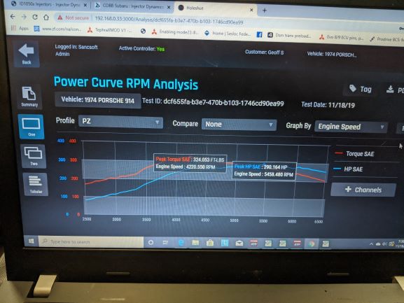
Posted by: Andyrew Nov 20 2019, 07:55 AM
Very sorry to hear about your mother!
325lbs of torque is MOVING!
Did the tuner tune with any E85 in the system?
Congrats on getting it running!
Posted by: strawman Nov 20 2019, 11:36 AM
Did the tuner tune with any E85 in the system?
Thanks Andy for your kind words. The current tune doesn't include E85, but it is apparently pretty easy for Mike to add using his COBB AccessPro software setup. The fuel pump, lines and injectors were sized/installed with E85 in mind. The COBB flex-fuel module will automatically adjust the tune based on the percentage in "corn" in the fuel. I also installed a petcock on the bottom of the fuel tank to easily empty the E85, since it apparently gets "stale" pretty quickly if it sits. I merely need to replace the COBB flex-fuel module when it arrives next week and then pay Mike to put it back on the dyno for final scaling.
Posted by: 914forme Nov 20 2019, 03:18 PM
IE85 likes to attract water, so add a fuel stabilizer and it will extend its shelf life. Do drain it, before you store the car for long periods.
Also do not forget you will use more E85 than normal gas so your range will be reduced, even before you get on it with the right go fast pedal.
Enjoy, that setup is a great way to go.
Posted by: Andyrew Nov 20 2019, 04:57 PM
Also e85 will eat up fuel lines really quicky. I would say that for storage you should keep regular fuel lines in the car or you'll be going through filters and lines quite regularly.
You can probably get away with say an e40 mix and get quite a bit out of it as far as knock protection and Hp increase.
Posted by: charliew Nov 21 2019, 11:36 AM
So sorry about your Mom, this really tests our faith. My wife is well into ad at about three years. We all have different little time bombs inside us. I hope I outlast my wife to study ad and help her as long as I can. My st judes pm had a recall on the battery 4 or more years ago (the problem was known in 2011) and getting it replaced is something it really takes a lawyer and money to have success at. Lawyers are cheaper than Dr's. The wealthly are really the only ones with better healthcare no matter what country they are in. I do not know of any field in which central texas has good specialists in health care. It's up to each of us to monitor our own care and to not trust our providers.
I'm still lurking but probably my expertise is pretty dated. My son had a 04 487hp sti on e85. It was not a stock internal 255 so not much relevance here except for the e85 part. the only reason he ran e85 was to keep detonation under control on the street. this was just a street/road car hobby for him. he sold it to someone in dallas a little over a year ago and moved on to a audi rs3 something or other. 400hp stock but tuneable to a safe 500 on the street also on e85 but it senses automatically the octane. It even starts the fuelpump when the door opens. He would not sell the sti to me, I had built a cold air intake and shrouded the fmic and made several little manifolds to help engineer the breather system using the mann provent used by lingfelter originally on our research. I'm sure he did not want to baby sit me on it as it required a laptop a lot on our changing weather to keep it optimum on performance. He always tuned it conservatively to save it. In Waco pop 120k he only had about two places to gas up which to me was a real pain but they were close to his workplace. I think any alcohol in fuel causes more problems for a street car than it is worth especially when you consider the places where you can use the torque. The quality of the e85 requires you to monitor it on every fillup to keep the tune optimum. Also because of the water issue you might want to not use a vented tank but use a closed tank system to keep the moisture out. If I missed your mods to control it I am sorry.
I think as you have decided that a race e85 tune is good though and the under 20 psi is good and probably a tune all the driveline can handle long term. The only thing I would think might be tested is the volume of the airfilter on full boost. the old formula of 1.45cfm for 1 hp might be used to size the filter and intake tubes.
I like following along on your journey.
Posted by: strawman Nov 23 2019, 07:48 AM
A pre-autocross pic of my 914 behind its TDI-swapped tow rig. I’ll provide an update after the race today. 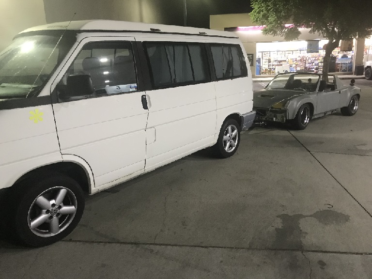
Posted by: ValcoOscar Nov 23 2019, 09:09 AM
Same here...sorry about your Mom.
She raised you well, glad I had a chance to meet and talk with you at our WCR2019 luncheon.
Guys/Gals...he won the 50/50 $$$ raffle and decided to pass. Very generous of him.
@http://www.914world.com/bbs2/index.php?showuser=17068 name came up next 
Hope to see your beast on the road soon.
Happy Holidays!!!
Oscar
Posted by: strawman Nov 27 2019, 12:49 PM
Well, that was short-lived! The first four runs were an absolute blast, with oodles of torque and instant acceleration. I experienced no flat-spots or other untoward tuning issues; it is a BEAST! Even the guy in the GT2-RS came over to see "what the heck you got in there?" In fact, I broke the tires loose in third gear (albeit on relatively cold tires) on a straightaway.
However, while in queue for my fifth run my oil pressure started to drop (30psi at idle, and only went up to 60psi at 3k rpm). Like an idiot, I didn't park it and decided to hammer it anyway. About halfway through the run, I heard the distinct sound of rod knock and then quickly a loud bang... followed by lots of steam. I immediately pushed in the clutch and drove through a wall of cones to get off the track ASAP. Once we verified it was not on fire, I found the motor was locked-up. So much for my junkyard motor...
I haven't done the post-mortem yet (I've been busy helping with another 24 Hours of Lemons), but it appears that I threw a rod through the top of the block and punctured the cast aluminum coolant crossover tube. Hence the steam mentioned above. I won't be able to spend any time with the car for a couple of weeks, but I've already ordered a new IAG Stage 2 short-block with a couple of upgrades. It includes a new Subaru case, 2017+ STI nitrided forged crank, forged rods and forged oversized slippery-skirt pistons, as well as an IAG windage tray. Hopefully my recently-rebuilt heads aren't borked, but I won't know until I tear it down. I'll send my BNR turbo in for inspection to make sure metal bits didn't get past the custom turbo filter (which, if full, could've starved it for oil!).
I learned a couple of things: 1) Duh, I really shoulda parked it when the oil pressure dropped, and 2) I need more traction. I will install an electronic oil pressure sensor that will pull timing/limit boost if it drops below a PSI threshold, and I plan to widen the rear flares to get more rubber in the back.
I'll snap photos of the carnage and the build-up of the real motor. It's only time-n-money...
Posted by: charliew Nov 27 2019, 01:24 PM
sorry to hear about the carnage. It will take a real effort to clean out the heads oil passages. The heads have the little restrictors in them that can be removed for cleaning. The oil cooler/warmer is toast, if you are still using it, maybe the pump is ok it can be checked of course. metal removal in a suby is a hard job. So what rpm did you push it to? Do you know about the smoothing of the ports on the block behind the oil pump? 60psi is a lot of pressure at 3k. hot 200 degrees at idle 30 psi is good in my opinion. I guess it is no 3 rod. I'm sure it will be better next time. 7-8 qts of synthetic in a pan with gates maybe? 18 psi doesn't seem like a problem on stock parts unless it is a high mileage motor. Since you didn't loose any oil check the level before you take it down and study how it is before you disassemble it will give you some knowledge to start the inspection. I would make a list of questions to try to answer for myself. I've never cleaned a accusump before.
so sorry but you are young and knowledgeable.
Posted by: strawman Nov 27 2019, 01:35 PM
Hi Charlie, the tune limits revs to 7k, but my datalog shows I never got above 6,054 during the two runs I remembered to hit the "datalog" button. I'm not using the OEM oil cooler/warmer due to the shape of the Smallcar cast aluminum pan... but oil temps never got above ~210F despite driving it hard and upper 70s weather. The former EJ22T engine would easily go over 220F after a few runs. I'll clean out the Accusump again (I bought it used) and replace the o-ring again -- pretty simple process. I'm going to have Pokrajac Tuning build the motor and talk to him about smoothing the port behind the oil pump; we'll see if my brand new 11mm pump needs to be replaced. As mentioned, it is a used engine -- out of a wrecked car with ~104k miles that wasn't drivable... so I couldn't put it through its paces on the road before pulling it.
Posted by: lierofox Nov 27 2019, 02:03 PM
Mental note: gotta drag strawman up north of the grade and have you poke around my ugly beast of an STI swapped 914. Remind you of what turbo lag feels like!
It's like waiting for VTEC, but with actual results!
Posted by: strawman May 27 2020, 01:36 PM
Sorry I haven't updated in a while. I moved to a bigger place (with a 30'x50' shop!), and finally dragged the 914 to my new place. The new engine is in the car, but I haven't started it yet. Stay tuned... I'll provide an update with some pictures in the coming days.
Here's a teaser: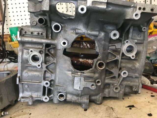
Posted by: strawman May 27 2020, 02:40 PM
As mentioned earlier, I heard a loud BANG at (according to my datalog) 5,130 rpms and then steam poured out of the engine bay. The car sat for a few weeks while I ordered the new shortblock and other parts in preparation for a new heart.
After removing the intake manifold I began to see what actually happened. As you can see in the first pic, the aluminum coolant crossover tube is cracked and you can barely see the hole in the top of the block.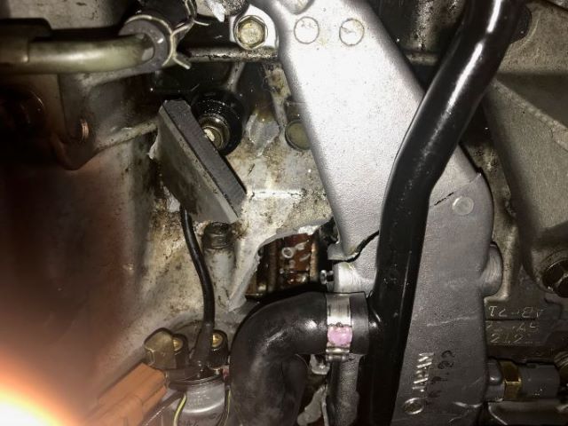
Here's a pic with the crossover removed; you can see the "custom venting" and several metal pieces laying about.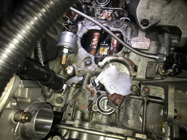
I pulled the drivetrain and placed the engine on a stand to begin the real tear-down. This is where you can see the real ugliness: that's what remained of the piston and one of the valve heads, and the upper half of the connecting rod sat at a weird angle. Check out the cylinder scoring, too.
Remember me talking about my totally rebuilt heads? Obviously, this head is beyond (feasible) repair.
Here's more carnage: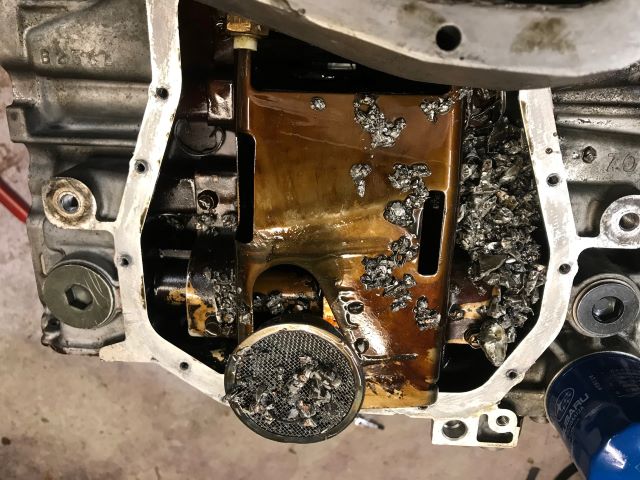
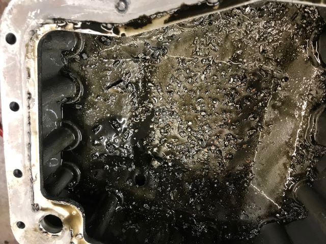
I don't have a pic of the turbo, but the hot-side impeller was damaged by all the metal pieces that shot through it. The intake was full of oil and small metal pieces, as were the cast iron exhaust manifolds. My brand new 11mm oil pump was surely damaged, too. Yuck.
So I sent the turbo back to BNR Supercars for a rebuild, and the 3-quart oil reservoir back to Accusump for a cleanout and reseal. I found a pair of used heads on Craigslist (after I had to send an Ebay pair back because the damage was not accurately described!). The heads I ended up using needed new exhaust valves, so I upgraded the springs throughout as part of the rebuild.
For grins-n-giggles, I separated the block to see more carnage. Obviously, the rod bearings were gonzo and the crank is junk. In my next post, I'll share the custom baffling I installed in the new block and in the oil pan -- and the hole in the now-empty block helped in devising the baffling solution.
Posted by: strawman May 27 2020, 03:46 PM
Obviously, the old engine was starved of oil so I worked with my tuner to prevent a similar fate for the new engine. Although my COBB AccessTuner can display oil pressure and log it, there is no shut-down like we have on the buses here at work. COBB says they're working on something to at least sound an alarm, but it looks like I'll need to closely monitor it. Speaking of oil, the Smallcar cast aluminum pan is great for providing additional clearance while only giving up 1/2 quart of oil, but there is zero baffling inside. Further, the modified Smallcar oil pickup is suspended (no bracing) and it sits near the front of the engine -- so all the oil rushes to the back of the pan under acceleration. Did I mention this thing is a rocket under boost? Yeah, that ain't gonna do...
After cleaning everything up, I bolted the oil pick-up and pan to the bare "vented" block. Through the hole, I could easily trace the outline of the pick-up onto the floor of the pan through the block, which helped me figure out how to best baffle it. 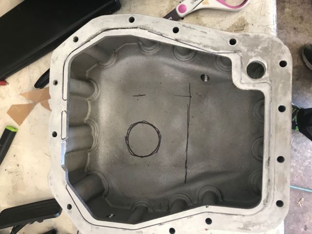
I bought a set of aluminum flapper baffles from Summit, which I installed in the custom-fit "can" around the pick-up. Below are pics of the mock-up and then as welded-in. As you see, I used flanges at the bottom to help with TIG welding, since I knew it'd be a challenge to mate the aluminum sheet and relatively porous cast pan. The flanges at the top provide some rigidity. I used SS rivets to secure the flappers to the walls of the "can." The holes behind the hinged section are barely smaller than the flap itself, so it flows well back into the can while returning oil constantly fills it.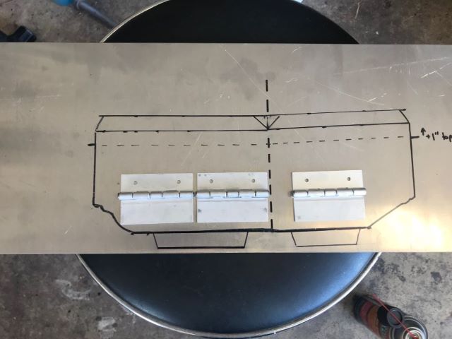
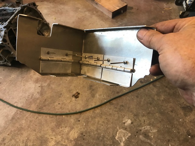
The welds ain't pretty, but I filled it with water and frantically ran figure-8s around my driveway to make sure the fluid will stay inside of and return to the can (I'm surprised my neighbors didn't call for the guys in white lab coats!). Not very scientific, but I hope it'll work and save the considerable investment that I have into my new engine setup.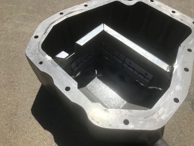
Finally, I wanted to shore up the Smallcar shortened oil pump pick-up; even the factory one has a bolted-on brace. So I bent up some scrap steel, cut-off the upper portion from the factory brace and welded it together. I then mocked up a rig to test for air leaks using old radiator hoses and clamps, some PVC caps, and pressurized it under water. It is tight! You can also see the IAG windage tray, which helps keep the oil in the pan and away from the rotating assembly.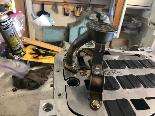
Final pic is of my new shop. Yup -- I have an old Benwil 12k lbs. 4-post lift, an Atlas 9k 2-post lift, and a shi**er in the corner. So far, I've installed twelve 17.7K-lumen LED lights (bright as WalMart!), wired up 38 pairs of 20-amp 110V plugs throughout, and three 30-amp 220V plugs for my MIG welder (each lift has one). Still need to wire in a 50-amp for my TIG, but I'm waiting for a new/larger panel that will be installed as part of the solar system in the next few weeks. The compressor will be installed under the lean-to. I bought a bunch of old pallet racking and an old Cat V50D forklift to help move-n-store big stuff. I still need to install the workbenches and small-stuff shelving. One small corner is reserved for my wife's lapidary stuff; maybe we'll spend more time together now? 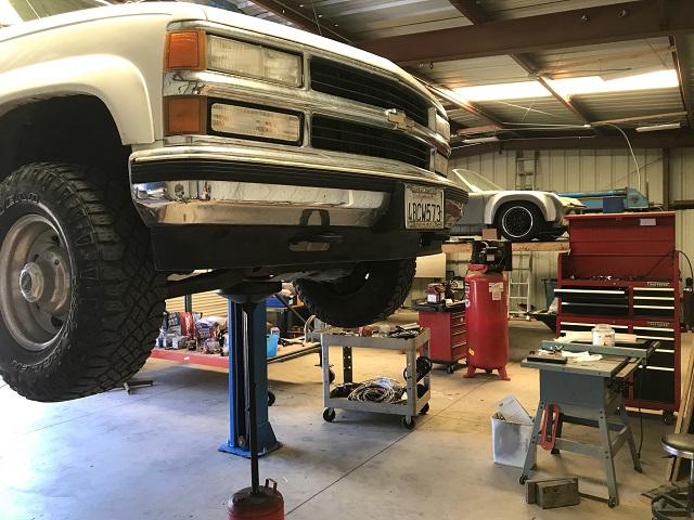
Posted by: 76-914 May 27 2020, 06:04 PM
Geoff, first I want to offer my condolences on losing your Mom. We were on vacation then & I totally missed that. I would liked to have known her. Rock solid and salt of the earth. Now I know where you get your resourcefulness. I like your baffle mod. Your new shop is the Cat's Meow buddy. Kent
Posted by: charliew May 27 2020, 07:37 PM
I wish you had a 7-8 qt pan.
Posted by: JRust May 27 2020, 10:03 PM
Geoff man did I miss a bunch. None of it good. So sorry to hear about your mom.
Totally missed your earlier post on your motor going boom. Man can I relate. Had mine running 2 weeks before it spun a bearing. Finally got it back with another used 02 2.0 turbo motor. Guy left my ebrake partially engaged when it was on the dyno run. Passenger rear caliper leaked like a sieve after he got the tune done. Waiting to rebuild my damn caliper so I can actually drive my car
Well that shop is sweet man! Congrats on that & your new build is going to be sweet
Posted by: strawman May 28 2020, 02:01 PM
Thanks for the kind words, it means a lot to me. We had to postpone Ma's planned memorial and ash-scattering due to the COVID-19 pandemic. I think about her everyday, which makes me appreciate friends-n-family even more than ever.
Charlie, while the pan holds a half-quart less, I have added 3 quarts capacity with the Accusump. My oil gauge showed no elevation in temps even when flogging it up the canyons, on the dyno, or at its sole solo race. I'm willing to add an oil cooler in the future if hotter summer temps suggest it is necessary.
Posted by: lierofox May 28 2020, 02:38 PM
Mike Pokrajac... are they any relation to a Nick Pokrajac by chance?
Posted by: strawman Nov 8 2020, 09:36 PM
Wow, it has been another six months since I last updated. Long-n-short of it is that the new engine rips. I had a lot of fun putting on the 800 miles break-in miles, although I finally added the rear window to reduce in-cabin noise (the Tial turbo blow-off valve is right behind my head!).
First pic is of the initial dyno pulls on the new engine. It is running premium gas in this pull, but it is completely set up for E85. As shown, it achieved 302hp at 6,079 RPMs and 334 ft/lbs torque at 4,112 RPMs. E85 helps cool combustion and allows higher boost levels, so I can't wait to see how E85 feels. That'll come over the winter.
Next up is a pic of my beast behind my trusty old Suburban at a PCA autocross on August 15 at Santa Maria Airport. 
The first two runs were a battle for me to get traction, but the third run was a good one. However, I heard a weird clunk when shifting and pulled over to my pit area to get a closer look. Yup, I found the next weakest link...
Posted by: strawman Nov 8 2020, 10:16 PM
I completed hashed the transaxle crossmember -- I could move the trans up/down about two inches with my bare hands. So I hooked the car back up to the Suburban and pulled it home to get a closer look and to plan for the repair. First, I removed the drivetrain (I'm getting too good at this ), and quickly realized that starting over would be better than trying to fix it.
First two pics show how the spot welds pulled through, followed by the gap between the crossmember and the trunk floor. Final pic is how badly cracked it was when pushed back up.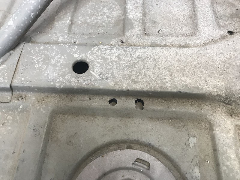
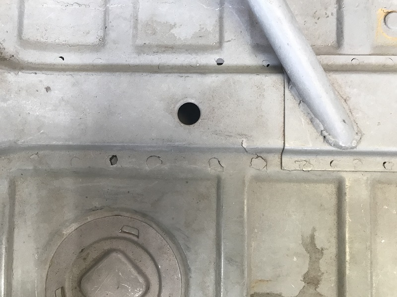
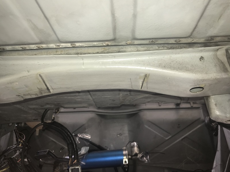
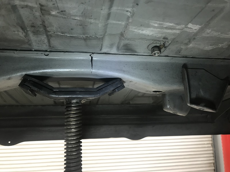
So I built a jig to locate the replacement mounts. I used the factory holes near the lower rear rail pinch welds for the fore-aft, and then triangulated it off holes in my modified rear firewall. You can see where I used sheet metal screws to cinch up the crossmember to the trunk floor. I hadn't yet drilled out the two holes for each trans mount when I snapped the pictures.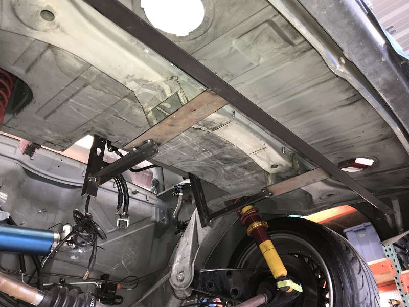
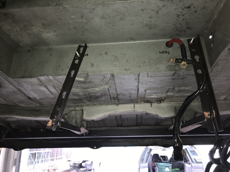
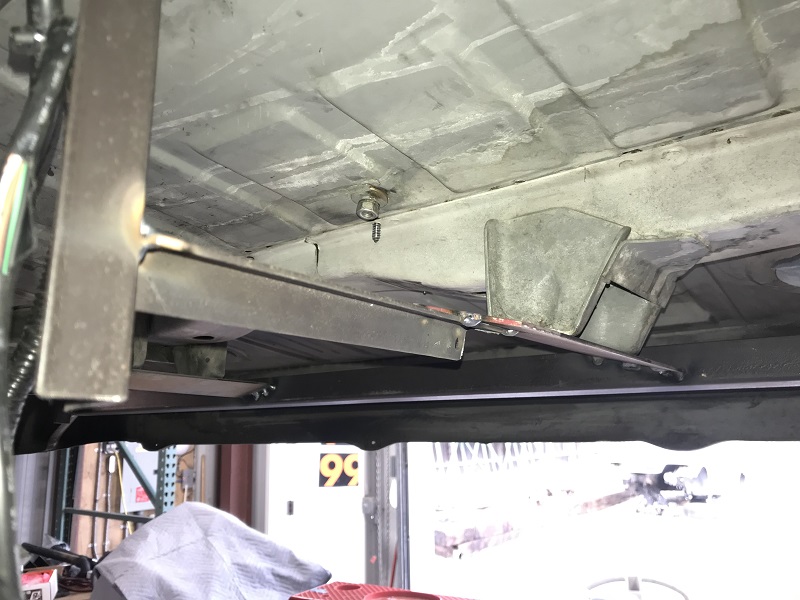
To provide a good solid basis, I used 2' x 4' by 0.120" wall rectangular tubing for the lateral. I already have the GT reinforcement kit welded in, but I needed to extend it back about four inches toward the rear to provide a strong base onto which to weld the new lateral tube. I used 2" x 2" by 0.120" wall for the the vertical standoffs, and angle iron to provide the mounting faces for the transmission mounts. I ended up using URO HD engine mounts, since the mounting holes were a little more favorable. They're also dirt-cheap and well-regarded. You can also see the patches I've welded-in to close it up; I still need to finish up some other patches and to seal everything up.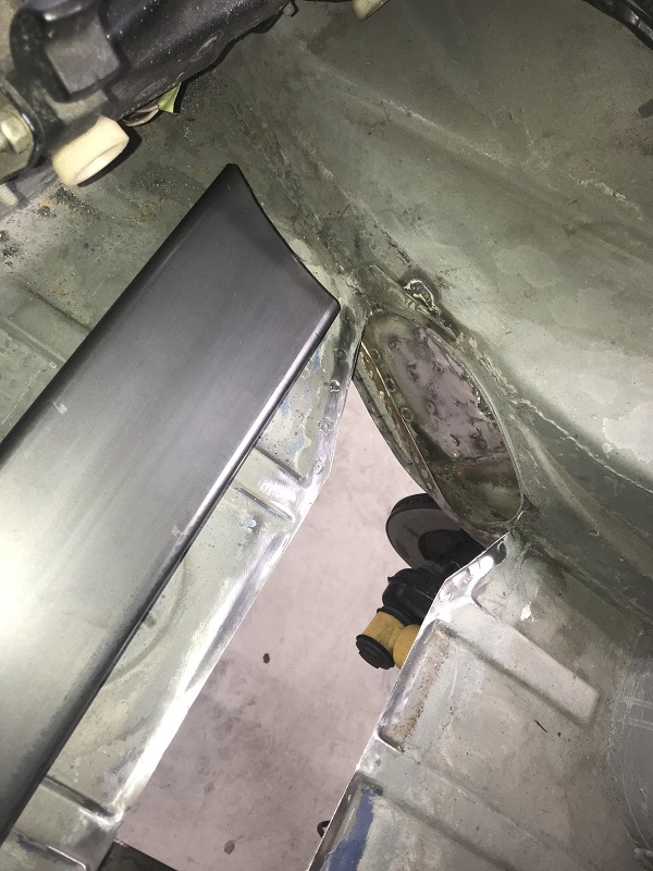
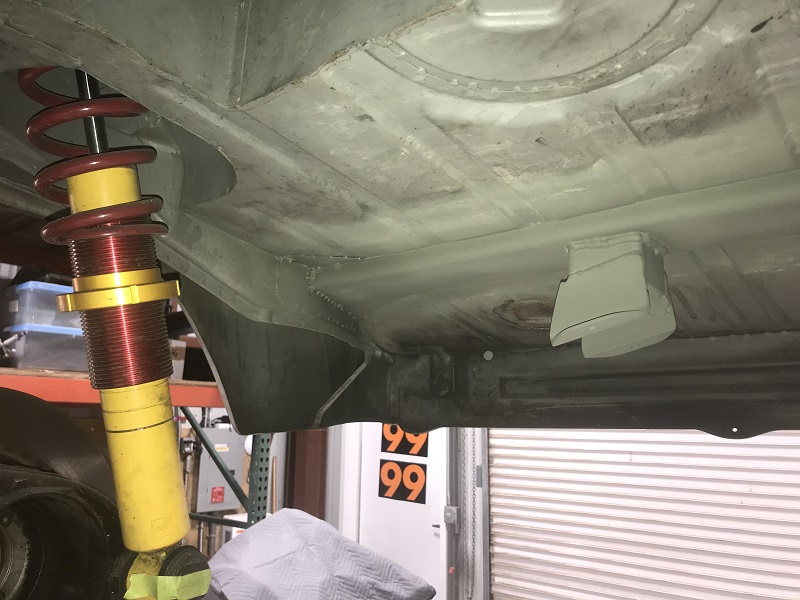
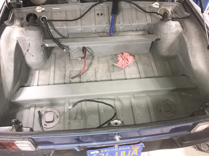
After a 13-hour slog to get it ready for an autocross the next day, it was running again. Everything bolted right back in (phew!) but I was dead-dog tired. After only four hours of sleep, I drove off to the race. However, apparently I did not secure one of the two air-to-water intercooler hoses correctly, and I rubbed through a hole after my second run. I could have attempted a heroic fix (a 3/8" Craftsman deep socket looked like it would work!), but I was frankly exhausted. So I parked it. I fixed the hose in the next few days and have enjoyed hammering on the car these past couple of months. Best of all, the car ran great during WCR 2020.
Posted by: 76-914 Nov 9 2020, 10:30 AM
That's one Hell of a Crack Jeff. I wonder if we'll being seeing more of those with the increase in torque on these cars?
Posted by: rmarx Nov 9 2020, 11:15 AM
I got a ride in that beast at WCR2020. That thing is fast!
Posted by: Cairo94507 Nov 9 2020, 03:56 PM
I was behind Jeff and his wife as they got on the freeway- it was a smooth left turn, wide onramp and Jeff "got up in it" a bit and it was smoking the tires as it was drifting around the turn....very impressive and sounded great too.
Posted by: strawman Nov 9 2020, 07:36 PM
I wonder if we'll being seeing more of those with the increase in torque on these cars?
Missed you at WCR this year Kent! But I sure hope you guys don't also experience the same failure. I neglected to mention that the factory crossmember was rotting a bit from the inside-out; nothing you could see from the trunk or underside, but certainly patina'ed deeply on the inside.
The fix is not for the faint of heart: it was a beeotch getting the curves at the outer ends of the new crossmember just right. I used two 18" pieces as template "mules" and then welded them together using a couple pieces of scrap angle iron to connect them just to make sure one piece would fit back in. Then I traced the compound end angles onto a single piece before cutting and cajoling it into place. I'm sure I spent 25 hours in mocking up the jig, cutting out the old pieces, devising the vertical standoffs, and welding in the crossmember... does not count removing and reinstalling the drivetrain!
What's gonna break next
Geoff
Posted by: strawman Nov 9 2020, 07:38 PM
I was behind Jeff and his wife as they got on the freeway- it was a smooth left turn, wide onramp and Jeff "got up in it" a bit and it was smoking the tires as it was drifting around the turn....very impressive and sounded great too.
Yeah, that caused an "upholstery cone" on the passenger seat! Nancy screamed at first and then bellowed with laughter for a few miles. It was nice meeting you and your brother at WCR2020. Your car truly deserved best in show!!!
Posted by: strawman Mar 4 2021, 05:58 PM
Long time without an update; much of my time lately has been getting my new-to-me 1975 914 "garage find" running.
I took my Suby-powered Beast to Guy Ober at SGS Motorsports in San Luis Obispo today to check my alignment and corner balance it. Turns out my string box alignment was pretty close on the front, while the back was actually toed out a bit. We also discovered that I need more camber up front. As a reminder, I'm running raised (by 30mm; see posts #84 & #93) spindles on 911 Bilstein Sport struts, 911 alloy front crossmember with 18.8mm torsion bars, along with Tarrett camber/caster plates and Tarrett sway bar, and Elephant polybronze bushings. However, Guy could only get -0.6 degrees on the left side and -0.4 on the right side. So I plan to install a pair of de-cambered ball joints to pick up another -0.75 degrees.
The rear has Ground Control coilover sleeves on Bilstein dampers with 250 in/lb Eibach springs and Elephant polybronze bushings. The settings remain at -1.1 degrees on the left side and -1.0 on the right side, with zero shims on either side. Toe is set at 0 degrees front and rear, since the Beast is mainly used for autocross and backroad fun.
With a half-tank of gas and 160 pounds in the driver seat, my car weighs 2,077 pounds. Guy was able to corner balance it within 1%. Note that I essentially have no interior (only two Miata seats, seat belts, and some gauges), no side windows, no carpet, no door panels, no engine lid, etc. I also have no front bumper, although the 914Werks flat tow bracket is installed; the rear bumper is steel but with no bumper top, and no valances. Surprisingly, the front is 886 pounds, while the rear is 1,191 -- this 42.7% front / 57.3% rear is almost 911 taildragger territory. Guy recommends trying to get more front bias to more optimally balance it.
On the short drive back to my office the car seemed to exhibit less dartiness; the former rear toe-out made it a little twitchy, I guess. I'm running a Vapor Trails Vettes club autocross on March 13 at the Santa Maria Airport venue, so I'll get a chance to see how the corner balancing and new alignment really works. I've been avoiding true autocross tires in order to get a truer feel of the car without masking my mistakes with stickies. I'm currently running Dunlop Direzza tires -- 225/45-16 rear and 205/50-16 front, but they're due for replacement relatively soon.
Posted by: Mike Bellis Mar 4 2021, 09:20 PM
Very cool. I need to do this.
Posted by: strawman Mar 23 2021, 06:04 PM
A quick update on tires: I participated in a Vapor Trails Vettes autocross on March 13 (the day after I got my first Moderna vaccination shot! ), and realized that my tires are toast. I've competed in nine autocrosses on these tires, as well as about 3k street miles since I installed them in February 2017. The bottom line is that I could not put power down (tires broke loose in 2nd and 3rd gears), and I ended up spinning out on my last run heading into last chicane... not counting five cones I picked up in the previous six runs. In short, they were GREASY despite having a lot of tread remaining.
The old wheels are 3-piece racing BBS Motorsports E52s measuring 9"x16" in rear and 8"x16" in front. Backspacing is 5" both in rear and front. The worn-out tires are Dunlop Direzza StarSpec IIs measuring 225/45-16 in rear (23.5" diameter, 10" overall width and 8.25" tread width) and 205/50-16 in front (23.75" diameter, 9" width, and 7.5" tread width). With this setup, in the rear I had 1-1/8" clearance to the inner "frame" (including thickness of welded-in GT kit) on the driver side and 1-1/4" on the passenger side; both sides had 3/8" clearance to the lip of my steel GT flares. I use one 21mm 944 spacer for the front to help widen the track; plenty of clearance to the strut tube.
Due to my increased power, and the improved braking and suspension, I can generate a lot more acceleration/deceleration than the old 200 treadwear Direzzas could accommodate. And finding wider tires in a 16" diameter is nearly impossible without going to R-compounds or very expensive Pirellis made specifically for old 930s. But I don't want R-comps until I fully sort the car (and can trust it). In short, it is my belief that stickies hide poor handling and technique.
So I could either re-barrel the BBS wheels to be 17-inchers for a ton of money, or just try out another set of factory Porsche wheels. For the time being, I went the latter route: I picked up a set of used 17" Boxster twists that included worn out tires (255/40-17 and 205/50-17) that helped me decide which new tire sizes to buy. The rear Boxster wheels are 8.5"x17" with 7" backspacing, and fronts are 7"x17" with 6-5/8" backspacing. I already have LONG racing studs, so adding spacers isn't a problem.
I then had Tire Rack deliver a set of new 200 treadwear Kumho V730 tires to my house in 255/40-17 and 225/45-17. They are slightly taller (24-3/4" rear and 24-5/8" front), which should help with gearing since I'm geared a little low with my 3.90:1 Suby Outback "Phase II" transaxle. I used 36mm spacers in the rear and 49mm spacers in the front, and clearance is about perfect.
The Boxster wheels are HEAVY compared to my BBS racing wheels -- each wheel/tire combo went from 38.2 lbs. to 48.4 lbs. in the rear, and from 36.4 to 43.2 in the front! Although my car has plenty of power, I'm wondering how much impact the extra unsprung weight will have on handling. My next autocross in April 10, so I'll report back afterward.
Below are pics of my tire changer and balancer, as well as the tires mounted up. I spent a lot of time cleaning the wheels, including scraping off the old remnants of tires and weights -- something that doesn't happen at your average tire shop. I neglected to add pics on the car, but needless to say I can/should lower it (and need to re-corner balance it ). Oh well, I need to install the decambered ball joints that I picked up from Rebel Racing Products anyway!
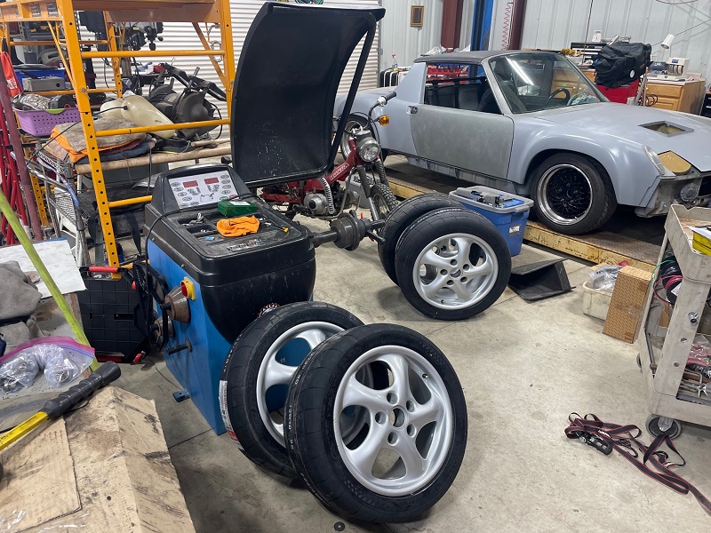
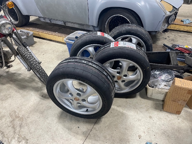
Interesting side note: Clint from Rebel was at the VTV autox with his damn cool 911R tribute car, and said he had the ball joints in stock and I should stop by his shop to pick them up on Monday. It turns out that I can see his new shop from my backyard! That sort of proximity is dangerous to my wallet...
Last picture shows the diameter difference between the old and new rear tires. 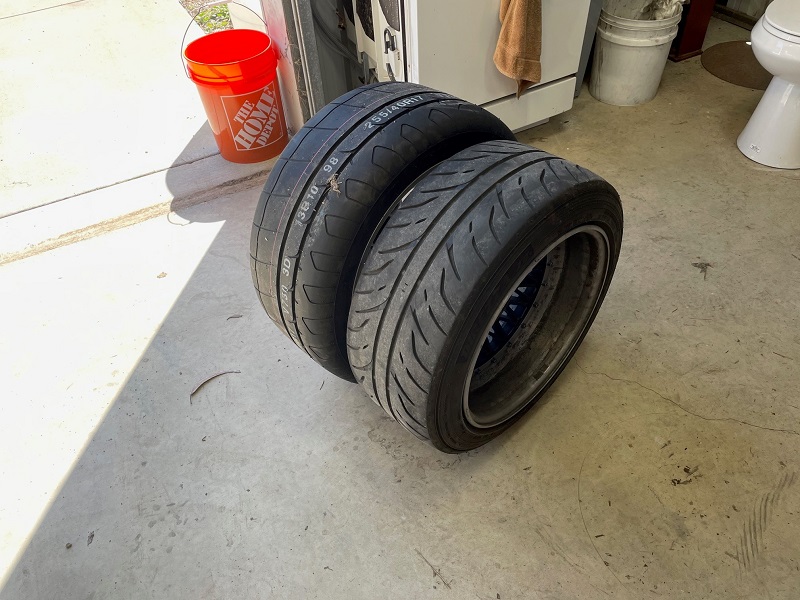
Posted by: Cairo94507 Mar 24 2021, 07:41 AM
Looking forward to see how those changes work out Jeff. I like the Boxster twist wheels.
Posted by: strawman Jun 28 2021, 04:45 PM
A quick update: the new tires are great! I have run two autocrosses with them: the PCA Central Coast Section event on June 5, and the Vapor Trail Vette's event on June 26. I came in 13th overall (out of 69) at the PCA event, and actually won the Open B1 class at the VTV event (despite locking up the front tires several times, I came in 5th overall). Here's a picture of my car on course.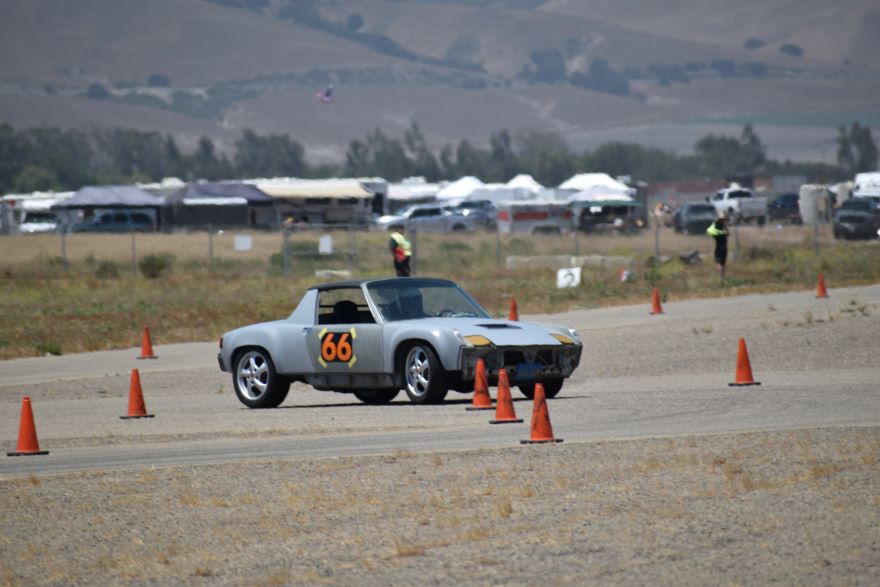
Yup, The Beast is ugly, but even the high-dollar car owners want to know "what's in there?"
I also I removed the harness bar from my green 914, and installed it and 4-point belts in The Beast -- which really helps keep me planted in the seat while on course.
I need to update my brake pads, and potentially transition to an adjustable proportioning valve. I'll give Eric a call...
Posted by: strawman Feb 29 2024, 03:47 PM
Wow, it's been almost 3 years since my last update. The biggest change is what I discovered after I finally figured out why the car braked unpredictably during autocross runs. I was usually competitive (usually in top 15 of ~65 cars) at local PCA and Vapor Trail Vettes autocrosses, but I was frustrated by its behavior at the limit: I kept locking up the front tires and the car "crab-walked" under extreme braking (more correctly, on the hairy edge of spinning!).
I worked with brake guru and all around nice guy Eric Shea to first restore my alloy S-calipers, and then rebuild and incrementally adjust my rear brake "pressure valve." I also installed new Porterfield brake pads, and new rubber brake lines. Still locking 'em up. I noticed a slight drip from my aftermarket 19mm master cylinder, so I bought a "correct" German one from Eric. When I went to install it, that is where the AHA moment occurred... when I built this car, I plumbed the left front MC outlet to the left front caliper, but I mistakenly swapped the rear output and the front right output! After correcting this dumbass mistake, I'm now consistently in the top 5 or 10 finishers in 2023.
I also enjoyed a great track day at Laguna Seca last August with PCA. Yes, my car still looks like a POS, but I passed a lot of nicer-looking and "faster" modern cars.
In another post, I talked about the mostly stock 1975 914 we bought for my wife to drive (The Beast sorta scares her!). We heard Pete Stout talk about the uniqueness and groundbreaking design elements of the 914 at the 2020 WCR, and Nancy insisted we buy a stock one. She really enjoyed driving it during the 2021 WCR, and we flat-towed it up to OR for the 2022 WCR to co-drive it around the PNW. We also towed it to the Red Rocks Classic in Utah in 2022. The car was formerly autocrossed here on the Central Coast in the 1990s by both a former GPR mechanic and the woman from whom we bought it.
Since then, I bought a whole trove of Porsche parts from Bill Chadwick’s estate last September. It included a running but not completed Subaru EG33-powered narrow bodied 1975 914, a 1974 914 parts car, five T4 engines, six 901 transaxles, and four trailer loads of 911, 912 and 914 parts. I'll finish up the EG33 car and sell it this summer. I cannot quit daydreaming about building the parts car into a Safari 914...
My other project is doing an upright conversion of a GA 2.0 T4 engine that I'll shoehorn into a 1956 VW Euro Oval Beetle. I'm putting it on a 1974 VW IRS pan, on which I've narrowed the front beam 2" (with adusters) for the CBP disc brake conversion (with 2.5" raised spindles) and I've narrowed the rear trailing arms 1" per side so that wheels fit correctly inside the slightly narrower Oval body. I'm also wrapping up a 5-speed 901 transmission conversion based on a ring/pinion-flipped 914 tailshifter. For induction, I've adapted Honda VFR800 motorcycle throttle bodies, and I'm using a Dub Shop crank-fire setup and Microsquirt ECU. I'm hoping to get this car up-n-running before year's end.
Next weekend is the first autocross of the year. Time to beat up on some Corvettes!!!
Posted by: tygaboy Feb 29 2024, 05:09 PM
Great to get an update! I've been wondering what you've been up to. Congrats on sorting the braking issue, too. Hope to see both again soon.
Powered by Invision Power Board (http://www.invisionboard.com)
© Invision Power Services (http://www.invisionpower.com)