Printable Version of Topic
Click here to view this topic in its original format
914World.com _ 914World Garage _ FI fuel and wiring routing
Posted by: watsonrx13 Jul 21 2008, 06:20 AM
I've put my engine back in the car and want to confirm the FI fuel routing. I've looked at PP/Dave Darling's diagrams, but would like confirmation: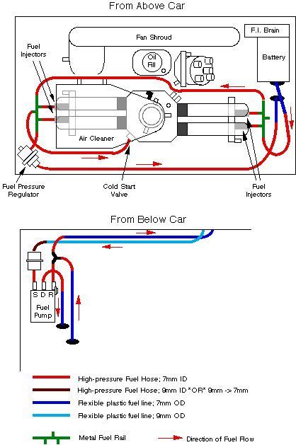
1. large (9mm) plastic fuel line from firewall connected to fuel filter
2. fuel filter connected to fuel pump at (S-suction) connection
3. (D-damper) connection on fuel pump connected to fuel rail on passenger side, rear connection
4. (R-return) connecton on fuel pump to Y connection
5. Y connection to small (7mm) plastic fuel line from firewall
6. Y connection to fuel pressure regulator
7. fuel rail on passenger side, front connection, to fuel rail on driver side, front connection
8. fuel rail on driver side, rear connection, to fuel pressure regulator
9. fuel rail on driver side, middle connection, to cold start valve.
Also, I'd like confirmation on the electrical connection to the fuel pump:
1. black/red wire to the + side of fuel pump
2. brown wire to the - side of the fuel pump
If I wanted to test the fuel pump outside of the car, I should be able to connect a positive wire to the + of the fuel pump, then to the + side of a battery, then - fuel pump to - battery. I could then connect the (S) fuel line and place in a container of gasoline. Then place the (D) and (-R-) fuel lines into an empty container. When I connect up the electrical lines, I should get the pump to hum and run fuel through the pump.
Also, if I turn on the ignition, I should be able to get voltage across the black/red wire and the brown wire, correct?
Finally, has anyone successfully found a shop that can rebuild these fuel pumps?
-- Rob
Posted by: swl Jul 21 2008, 08:06 PM
Daves drawing is right on from all accounts. Assuming of course we are talking about a 2 liter. Rest of the assumptions look good to me except:
Power across the fuel pump is only applied for 1.5(ish) seconds after key on then not again until the starter is engaged or the engine is running. To get constant power ground pin 3 on the 4 pin connector on the relay board.
Probably a good idea to connect the return line from the pump to your output container in your out of car test rig. You can get bypass fuel coming out there particularly with air in the system. These pumps don't pump air well so you might want to get the pump below the gas container and give it a little manual prime.
I haven't found a rebuild source. No rebuild kits either. You do see rebuilt pumps for sale but where they source the rubber parts from seems to be an industry secret.
Posted by: watsonrx13 Jul 22 2008, 06:28 AM
Steve, thanks for the reply. I forgot to add that yes I'm working with a '74 2.0l engine. Earlier this year I bought a FI fuel pump that supposedly worked. When I installed it and added power, I didn't get any humming, so I removed it and connected it directly to a battery, but without any luck. So, I tried another pump, hooked directly to the battery and got a hummer...  . So I connected everything back in the car and turned on the ignition, but no hummer. Since it appears that I'm not getting any power to the pump from the electrical system, I'm going to hot wire it. I'll try jumping the relay, but if that doesn't work, I'm going to run a hot wire (switched) from the fuse panel.
-- Rob
Posted by: swl Jul 22 2008, 06:40 AM
I'm not a fan of hot wiring Rob. The relay board looks a little daunting but it is relatively easy to troubleshoot and fix. Most of the time it is a relay or the fuse. I've also heard of the fuse holder needing to be fixed. If you spend an hour trouble shooting there you should be able to find the source of your problem. Be happy to talk you through it. A cheap multimeter is all you need.
There was thread recently about a fuel pump that would not spin. Turned out to be stuck brushes. It would be interesting to see if that is the problem with your pump that wont hum.
Posted by: watsonrx13 Jul 22 2008, 06:56 AM
Steve, thanks... I do have a multimeter, but I'm a little electrical-challenged... I'm currently at work, but any recommendations and/or steps you can give me to trouble shoot my electrical problems would be great. I've already swapped the relay with another known good one, but still no go. This past weekend I had a friend come by and while he turned the ignition on, I had the multimeter across the leads, but only registered 0.03 volts.
Also, how do I check the brushes in the motor?
-- Rob
Posted by: SirAndy Jul 22 2008, 12:20 PM

So I connected everything back in the car and turned on the ignition, but no hummer.
in order for the pump to work correctly, the FI brain must be hooked up and plugged into the relay board!
and you also need the pump relay in the board and the the fuse on the board.
 Andy
Andy
Posted by: watsonrx13 Jul 22 2008, 07:20 PM
So I connected everything back in the car and turned on the ignition, but no hummer.
in order for the pump to work correctly, the FI brain must be hooked up and plugged into the relay board! DONE
and you also need the pump relay in the board and the the fuse on the board. AND DONE
Andy Next, suggestion....

-- Rob
Posted by: Cap'n Krusty Jul 22 2008, 07:38 PM
The hose from the plastic supply line to the filter is 7mm on one end, 9mm on the other. The part number is 914 356 525 00, and it's readily available from your local Porsche dealer, although they may have to order it. Around 25 bucks.
DO NOT "make something fit". Fire's an ugly thing and, odds are, you'll have one if you cheap out on the job.
The Cap'n
Posted by: swl Jul 22 2008, 10:09 PM
Tab914 was the guy who discovered the brushes problem. I'm on the road and the hotel gateway is really fracking with my browser - can't give you a direct link but the thread is called 'fuel pump issues, no power to pump'
I've been searching for the thread with the relay board diagram but am getting frustrated by this browser thing. So I'll try from memory (dangerous!)
1 lift the power to your coil during testing to guard against welding your points.
2. key on
3. with volt meter measure from ground to each side of the fuse. Should be 12-13V on both sides.
4. if power to the fuse is good then uplug the 4 pin connector on the back left of the relay board. Use a jumper to ground pin 3 on the relay board to ground. This should turn on the pump but most likely won't
5 if the jumper failed to start the pump then we are probably looking at one of the two relays - main power or fuel pump. replace both with known good relays (headlight motors are a good source).
If none of that points to the problem then I need my diagram to take your farther.
Background.
The main power relay turns on with switched power from the key.
It then provides power to the solenoid of the fuel pump relay. The ecu then turns on a 'switch' to ground to activate that solenoid. When the solenoid makes it switches power that comes from the battery through the fuse, through the relay contacts and onward to the pump. Jumping pin 3 is basicly doing the job that the ECU does.
Posted by: SirAndy Jul 22 2008, 11:03 PM
Next, suggestion....
so, did you switch relays to make sure it's working?

also, a voltmeter is your friend. is the ground wire to the pump working?
 Andy
Andy
Posted by: roadster fan Jul 23 2008, 02:05 AM
Here is the thread that swl is talking about http://www.914world.com/bbs2/index.php?showtopic=84871&hl=fuel++pump++no++power
I had a problem with my ECU and those pics are in the above thread.
Jim
Posted by: watsonrx13 Jul 23 2008, 06:03 AM
Jim, thanks for the link, evidently I missed it originally. 
Andy, I'll use the flow chart and other references to check the fuel pump circuit. If I have all of the circuits working correctly, I'll disassemble the fuel pump and check the brushes.
Thanks again everyone... 
-- Rob
Posted by: watsonrx13 Jul 23 2008, 04:02 PM
Well, I read the postings and noticed that TAB914 (Dominic) disassembled the fuel pump. I was able to remove the (4) bolts on the top and remove that, but how do you remove the motor for the pump housing?
-- Rob
Posted by: swl Jul 23 2008, 06:17 PM
try pm'ing/emailing dominic - I don't think he is on regularly.
Any luck with the relay board?
Posted by: watsonrx13 Jul 23 2008, 06:26 PM
Not yet, unfortunately life has gotten in the way during the week...  I'm definately going to work on the car this weekend.... I'll send Dominic a PM to see if he can answer my question.
-- Rob
Posted by: swl Jul 23 2008, 06:49 PM
Not yet, unfortunately life has gotten in the way during the week...
I'm definately going to work on the car this weekendMe too - but substitute year for week
Had the backyard equiv of a hell hole repair. But it is done now and I'm going to get some 'me' time in the garage.Posted by: watsonrx13 Jul 23 2008, 07:41 PM
Not yet, unfortunately life has gotten in the way during the week...
I'm definately going to work on the car this weekendMe too - but substitute year for week
Had the backyard equiv of a hell hole repair. But it is done now and I'm going to get some 'me' time in the garage.That's right, you had the deck rebuild.... glad you got it completed....
Now back to the important/fun stuff...


-- Rob
Posted by: watsonrx13 Jul 28 2008, 06:10 AM
Well, this weekend I tried to disassemble one of the pumps that aren't working. After spending several hours I was finally able to get the bottom section off, but not until after I tried to shove a small bladed screwdriver through the webbing of my hand, between my thumb and fore finger. It appears that the wiring to the electrical contacts were broken, so I decided to throw it away. BTW, I'll NEVER try to disassemble a pump again... 
I also found that when I repainted the interior of the engine compartment, I didn't keep the paint off of the ground wire bolt underneath the relay panel. I was following Brad's flow chart and the first thing to check was the main power. Before I cleaned it, I had 0 volts, afterwards I had 6 v. According to Brad, if you don't have 12 v then there's a problem with the relay board and it should have the bottom removed and the connections checked and resoldered. I'm not going down that path. Steve (swl) had another list, but I didn't print it out to check, so that's the next step.
Anyway, I thought I'd keep everyone updated.... I'll let you know what the final outcome will be.
-- Rob
Posted by: swl Jul 28 2008, 07:37 AM
6 Volts huh - I guess you're halfway there
Where is that measured Rob.
Posted by: watsonrx13 Jul 28 2008, 06:29 PM
6 Volts huh - I guess you're halfway there
Where is that measured Rob.
I followed Brad Anders flow chart and the first thing to test was to remove relay 74 and wrap a test wire around pin 87 and plug it back in. Connect a DMM to the test wire and turn on the ignition. With the ignition on, I connected the + side of the DMM to the test wire and the - side of the DMM to the engine. I got 7 v.
Also, Steve recommended 'with volt meter measure from ground to each side of the fuse. Should be 12-13V on both sides.' When I connected the + DMM to either side of the the fuses and the - DMM to the engine, I only got 7 v. I'm assuming the fuse you're recommending in the fuse on the relay board.
So now the question is, why am I only getting 7v? BTW I bought a brand new Optima battery last week. When I test the battery, I got 12.6 v.
-- Rob
Posted by: swl Jul 28 2008, 07:20 PM
short answer is most likely contact resistance. Imperfect contact between two conductors caused by corrosion and crap.
You've traced it back to somewhere upstream of the fuse so there are two likely suspects.
most likely is the fuse holder where it connects to the printed circuit board. I've been searching unsuccessfully for the thread where someone described how they had to repair that.
Other possible is a bad contact on the 14pin connector at the top of the board. Pin 14 (left rear most) is where the power from the battery connects to the relay board.
The last check before resigning to a board repair is to pull the 14 pin connector off and look at the condition of the contactors both on the plug and the receptical. Green stuff is bad. With the plug disconnected try your multimeter on resistance (ohms) in the lowest range and measure from pin 14 to the right side of the fuse holder. It should be damned near 0 (there is a zero adjust on your meter - make sure you use it 'cause we're dealing with small resistances) - you may have to scratch around with the probe a bit to get a good contact. If it is several ohms that would suggest the fuse holder as the source. If it is 0 then perhaps the contact was the problem and you should be able to clean it up with some emory cloth.
Posted by: watsonrx13 Jul 28 2008, 07:36 PM
Thanks Steve, I'll check this tomorrow. Checking the schematic, the 14 pin is the driver's side rear and it's connected to the rear fuse, correct?
-- Rob
Posted by: swl Jul 28 2008, 07:43 PM
One last thought. When you have the 14 pin connector off check for 12v at pin 14 on the wiring harness itself just to confirm that the problem is indeed on the relay board.
Posted by: watsonrx13 Jul 28 2008, 07:45 PM
One last thought. When you have the 14 pin connector off check for 12v at pin 14 on the wiring harness itself just to confirm that the problem is indeed on the relay board.
I will and will report back tomorrow....
-- Rob
Posted by: swl Jul 28 2008, 07:59 PM
Thanks Steve, I'll check this tomorrow. Checking the schematic, the 14 pin is the driver's side rear and it's connected to the rear fuse, correct?
yup
Posted by: watsonrx13 Jul 29 2008, 07:55 PM
short answer is most likely contact resistance. Imperfect contact between two conductors caused by corrosion and crap.
You've traced it back to somewhere upstream of the fuse so there are two likely suspects.
most likely is the fuse holder where it connects to the printed circuit board. I've been searching unsuccessfully for the thread where someone described how they had to repair that.
Other possible is a bad contact on the 14pin connector at the top of the board. Pin 14 (left rear most) is where the power from the battery connects to the relay board.
The last check before resigning to a board repair is to pull the 14 pin connector off and look at the condition of the contactors both on the plug and the receptical. Green stuff is bad. With the plug disconnected try your multimeter on resistance (ohms) in the lowest range and measure from pin 14 to the right side of the fuse holder. It should be damned near 0 (there is a zero adjust on your meter - make sure you use it 'cause we're dealing with small resistances) - you may have to scratch around with the probe a bit to get a good contact. If it is several ohms that would suggest the fuse holder as the source. If it is 0 then perhaps the contact was the problem and you should be able to clean it up with some emory cloth.
OK, time to report back....
Steve, since you mentioned that one of the red wires comes off of the battery, I check for power at the 14 pin connector. I was only getting 7 v. I checked all of the red wires at the battery and one of the round clips fell off and there was a lot of corrosion/green stuff. I cleaned and/or replaced and then bolted them back to the battery. I then check the 14 pin connector and was now getting 8 v. I took the 14 pin connector cap off then cleaned around the pin. When I checked the pin on the connector I got 8 v, but when I checked the wire to the pin I got almost 10 v.
So my question is, how do I clean the pin holders in the connector and how do I clean the wires at the pin holders?
BTW, I checked ohms between the 14th pin and the right side of the fuse and got 0.002. So, I'm feeling that the relay board is probably good, but there's something wrong with the wiring. Also, someone else had already gotten to the 14 pin connector, because the casing around the wires had been sliced, then taped back up. Oh, and I rechecked the right side of the fuse holder and was getting almot 10 v and I cleaned the fuse holder prongs.
Any other suggestions?
-- Rob
Posted by: swl Jul 30 2008, 07:42 AM
That sliced casing is looking pretty suspicious. Did you unwrap the tape and see what was under there? A splice maybe?
I had the same sort of problem at the battery post as you describe. That would certainly have been the most likely cause of the majority of your problem. Just make sure your repair job is making good contact.
So far you've done everything I would have done so I don't have much more to offer you. I've checked the wiring diagram and it confirms that it is a straight run from pin 14 to the battery. So we have the connectors on both ends and the conductor itself as the only source of the loss.
By the sounds of things you already know that the back side of the plug slides off to expose all the pins. Those pins can pull up and out through the plug. That notwithstanding I would probably do my cleaning with the pin still in the plug. I get nervous about brittle wires. Never the less you can inspect the pin from that vantage point and get right on the conductor instead of the pin to measure for voltage. Thats what you meant when you said you are getting 10v at the wire right?
I suppose in the worst case scenario you could run a new wire from the battery but that would be very fidgety to get it to fit into the plug. You would also want a new pin and I haven't a clue where you would get one. This is getting into Jeff Bowlsby's area of expertise. He's the wiring harness guru. Maybe send a shout out to him.
Posted by: watsonrx13 Jul 30 2008, 11:20 AM
I agree about running another wire from the battery to the pin holder and trying to replace/resolder. I still don't know how or what to use to clean the 14 pin connector, I've used the spray electrical cleaner, but if someone has another suggestion, please let me know.
My other concern about the lack of power to the board is, 'will this effect any other circuit/electrical device associated with the FI system?'
I have a used, known in good condition, fuel pump on the way and I'll try to test it outside of the car before I install it.
Steve, thanks again for taking the time to walk me through this process, I really appreciate it.
If I find any other solutions, I'll post them here...-- Rob
Posted by: swl Jul 30 2008, 12:38 PM
The only other things that use the power from pin 14 are the heater blower and the rear window defogger.
The other critical stuff like the ECU is coming off power that is supplied at pin 12. You should probably check out that one. Pin 8 carries switched 12v to your coil - another critical of course.
The only thing I can suggest for cleaning the pin and socket is very fine emory cloth. There are things like tuner cleaner but that is more for dust and minor oil. Art erasers work really well too but you can't really get that to work with things as small as this. Great for cleaning the ecu connectors though.
Posted by: smg914 Jul 30 2008, 02:51 PM
I can personally recommend a contact cleaner called De-Oz-Id, it comes in a small aerosol spray can.
Posted by: swl Jul 30 2008, 03:33 PM
hey that sounds interesting! I didn't have any luck under deozid but did find a deoxit http://www.adorama.com/HOD5S6.html
Where do you find this stuff? It could be a godsend.
Posted by: smg914 Jul 30 2008, 11:27 PM
Actually it is DEOXIT and I purchased it at Radio Shack. Good stuff.
Posted by: watsonrx13 Jul 31 2008, 05:46 AM
Thanks Steve, I'll pick some up this weekend and try it...
-- Rob
Posted by: watsonrx13 Jul 31 2008, 05:53 AM
OK, I just received another FI fuel pump, but it's for a later 2.0l engine which only has (2) ports.
1. Can I mount this pump in the same place in the engine compartment?
2. Can I assume that the S (suction) port will still connect to the fuel filter (which comes from the fuel tank), the R (return) will connect to the passenger side fuel rail and the fuel pressure line will connect to the return line that goes to the fuel tank?
3. Any concerns with this arrangement?
-- Rob
Posted by: swl Jul 31 2008, 06:34 AM
from what I've been able to figure out the third port serves two purposes. It prevents an over pressure situation and it assists in priming the pump. I don't claim any expertise but I don't think either are necessary. Obviously the porsche guys had the same opinion. The pop off valve opens whenever there is air in the system sending the air directly back on the return line. In the 2 port system that air would get sent around the FI loop before it gets out of the system. This means it would get compressed and maybe hammer the components a bit. Just keep this in mind when you first start it from a no gas situation - maybe run it a bit before attempting to start it.
Plumbing is identical just eliminate the 'y' where it went back to the 'r' port.
Posted by: watsonrx13 Jul 31 2008, 07:30 AM
Thanks Steve, that's what I thought...
-- Rob
Posted by: watsonrx13 Aug 12 2008, 06:54 PM
Time for an update....
Received new FI fuel pump and it works off of the car. I then mounted it to the car, but still no power. I ran a hot wire from + battery to + fuel pump, leaving the - fuel pump wire hooked up from the wiring harness, fuel pump runs and fuel circulates through the lines and dumps back into the fuel tank....
Next, retested the relay board. Checking the fuse holder and pin 30 on the realy board for the main relay and the fuel pump relay and got 12.25 v. Before, I wasn't using a good ground.
I began following Brad Anders flow chart and it failed on the first test. Wrap a wire around pin 87 on the main relay, insert back into the board, switch on ignition and test for 12 v. FAILED... remove backing of relay board and test printed circuits (I'm NOT doing that). So I found another relay board, tested and got the same results...
OK, I decided to check the timing. I installed new rotor, dist cap, points and condensor, spark plugs and wires. Hooked up the timing light, turned engine over using a remote starter.... No light from timing light.... OK, I then removed a spark plug and grounded to the block, turned over the engine, no spark.... OK, I disconnected the coil wire to the distributor, then turned over the engine, no spark...  Finally, called Joe and told him I don't have power to the coil. His recommendation was to put a + wire directly from the battery to the + coil. I turned over the ignition and I have spark....
Joe said that there is probably a fault in the ignition switch that's not turning on the coil, but I can start the engine with the ignition switch....
So my question is, can the ignition switch be causing a power issue with the relay board?
-- Rob
Posted by: swl Aug 12 2008, 08:58 PM
Yes. The power that energizes the main power relay comes from the ignition switch. No main power = no power to the fuel pump, ecu or ignition coil. Pull the main power relay and check for 12 v at pin 85. Key on of course. By the sounds of thing Joe has it nailed. Current for the starter goes through a separate set of contacts in the ignition switch.
Posted by: swl Aug 12 2008, 09:12 PM
also looks like the same contacts on the ignition switch feeds the brake lights and backup lights - that would be quick confirmation.
Posted by: watsonrx13 Aug 24 2008, 01:25 PM
First off, I want to thank everyone (especially Steve - swl) that has contributed to this post, your suggestions have been invaluable.
Now the update. The problem with no power to the relay board was caused by the 14 pin connector. Evidently, when I took the cover off, one of the pins moved and was put back in the wrong hole. The #8 pin ended up in the #6 hole. BTW, there should not be any wires going into the #6 hole. After I finally made the correction, Steve Gaglione came by today (Sunday) and helped me try to get the car started. I have power to the relay board, coil, fuel pump and fuel injectors. We turned the car over and it fired right up..... But, it's idling at 3000 rpm. We checked the routing of the new vacuum lines and everything appears to be correct. After searching this site, it appears that either the PCV valve is plugged (and will be replaced) and/or the AAR is stuck or a vacuum leak somewhere.
So, the final diagnosis:
1. fuel pump inoperatable, replaced with (2) port pump
2. clean ALL of the electrical contacts in the relay board and ground wires
3. verified that the 14-pin connector had the correct wires in the correct holes - (1) was in the wrong hole
4. previously replaced ALL fuel and vacuum lines with new ones.
5. previously tested and rebuild ALL fuel injectors.
6. new plugs, wires, distributor cap, points, condensor
7. new runner boots
Anyway, I just wanted to finish this post regarding power problem I was having....
-- Rob
Powered by Invision Power Board (http://www.invisionboard.com)
© Invision Power Services (http://www.invisionpower.com)